EM 1110-2-1100 (Part VI) Proposed Publishing Date: 30 Apr 03 VI-5-64 Fundamentals of Design Figure VI-5-36. Illustration of superstructure designs causing insignificant and significant reduction in front slope armor stability • Structure trunk stability. Stability formulae for front slope armor on structure trunks are presented in the following tables outlined as follows: Armor Unit Non-Overtopped Overtopped Submerged Rock Tables VI-5-22/23 Tables VI-5-24/26 Tables VI-5-25/26 Concrete cubes Table VI-5-29 Tetrapods Table VI-5-30 Dolosse Table VI-5-31 ACCROPODES ® Tables VI-5-32/33 CORE-LOC ® Table VI-5-34 Tribars Table VI-5-36 • Information on rear side armor stability is given in Table VI-5-28. A formula for stability of reef breakwater is presented in Table VI-5-34. A formula for stability of armor in front of a vertical wall is presented in Table VI-5-35. Rubble-mound structure head stability is given in Tables VI-5-37/38. Parapet walls are placed on top of rubble-mound structures to reduce overtopping by deflecting the uprushing waves back into the sea. This generally reduces the front slope armor stability. A low wall behind a wide front armor berm will hardly affect the armor stability (see Figure VI-5-36a). On the other hand a high wall with a relatively deep foundation situated behind a narrow front armor berm will significantly reduce the armor stability (see Figure VI-5-36b). • No generally applicable formulae are available for reduction in front slope armor stability caused by parapet walls. • Laboratory test limitations. All of the various armor stability criteria represented by the equations and empirical coefficients in Tables VI-5-22 to VI-5-36 were developed in laboratory physical models, most often at reduced scale. Although field experience has added validation to some of these stability formulae, designers should be aware of the following limitations when applying laboratory stability results to prototype conditions.
Transcript
EM 1110-2-1100 (Part VI)Proposed Publishing Date: 30 Apr 03
VI-5-64 Fundamentals of Design
Figure VI-5-36. Illustration of superstructure designs causing insignificant and significantreduction in front slope armor stability
• Structure trunk stability. Stability formulae for front slope armor on structure trunks are presentedin the following tables outlined as follows:
Armor Unit Non-Overtopped Overtopped Submerged
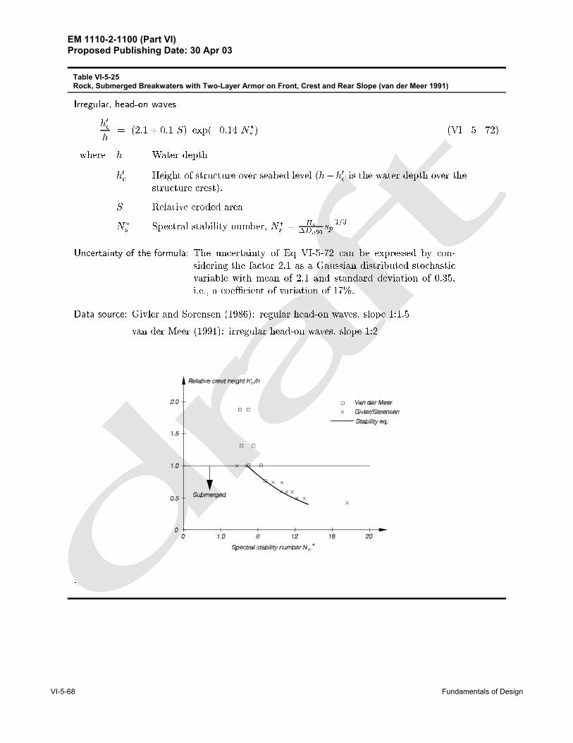
Rock Tables VI-5-22/23 Tables VI-5-24/26 Tables VI-5-25/26
Concrete cubes Table VI-5-29
Tetrapods Table VI-5-30
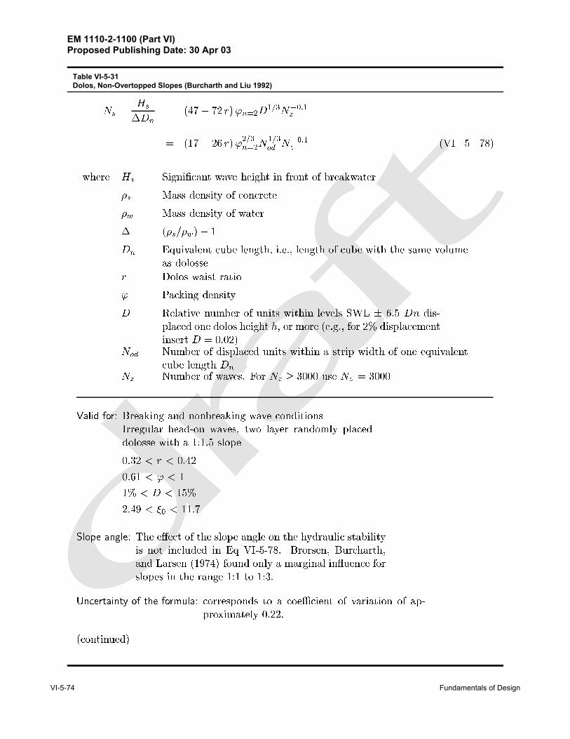
Dolosse Table VI-5-31
ACCROPODES ® Tables VI-5-32/33
CORE-LOC ® Table VI-5-34
Tribars Table VI-5-36
• Information on rear side armor stability is given in Table VI-5-28. A formula for stability of reefbreakwater is presented in Table VI-5-34. A formula for stability of armor in front of a vertical wallis presented in Table VI-5-35. Rubble-mound structure head stability is given in Tables VI-5-37/38.Parapet walls are placed on top of rubble-mound structures to reduce overtopping by deflecting theuprushing waves back into the sea. This generally reduces the front slope armor stability. A lowwall behind a wide front armor berm will hardly affect the armor stability (see Figure VI-5-36a). Onthe other hand a high wall with a relatively deep foundation situated behind a narrow front armorberm will significantly reduce the armor stability (see Figure VI-5-36b).
• No generally applicable formulae are available for reduction in front slope armor stability caused byparapet walls.
• Laboratory test limitations. All of the various armor stability criteria represented by the equationsand empirical coefficients in Tables VI-5-22 to VI-5-36 were developed in laboratory physicalmodels, most often at reduced scale. Although field experience has added validation to some of thesestability formulae, designers should be aware of the following limitations when applying laboratorystability results to prototype conditions.
EM 1110-2-1100 (Part VI)Proposed Publishing Date: 30 Apr 03
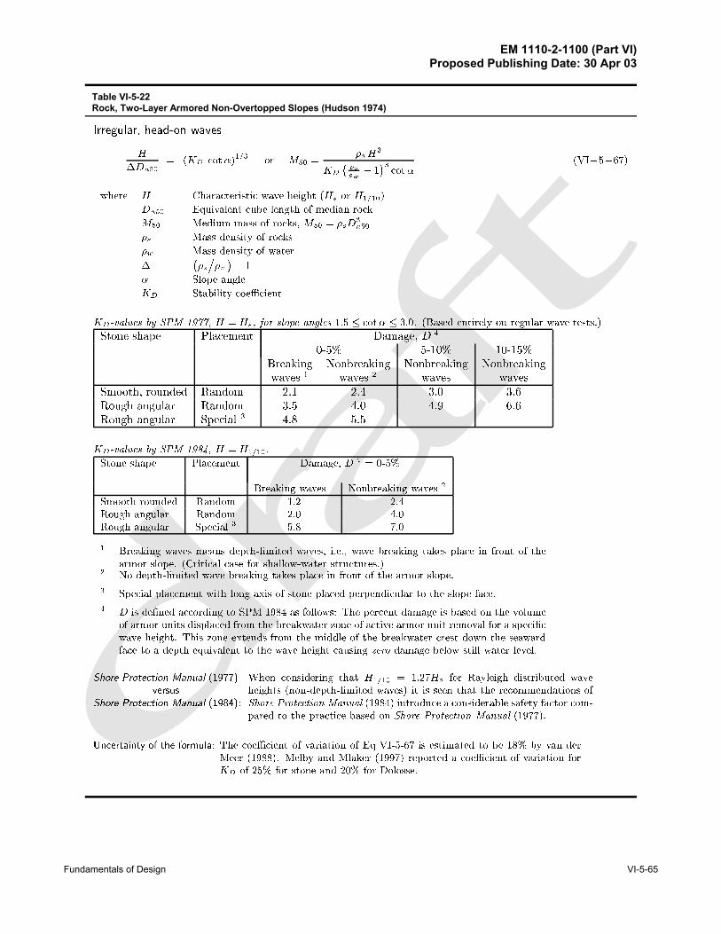
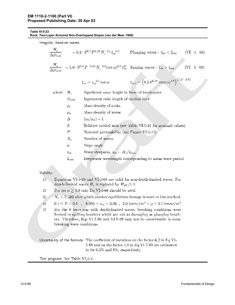
Table VI-5-23Rock, Two-Layer Armored Non-Overtopped Slopes (van der Meer 1988)
EM 1110-2-1100 (Part VI)Proposed Publishing Date: 30 Apr 03
Fundamentals of Design VI-5-67
Powell and Allsop ������ analyzed data by Allsop ������ and proposed the stability formula
Nod
Na� a exp
hb s����p Hs� ��Dn���
ior
Hs
�Dn���
s���p
bln
��
a
Nod
Na
��VI����
where values of the empirical coe�cients a and b are given in the table as functions of freeboardRc and water depth h Nod and Na are the number of units displaced out of the armor layerand the total number of armor layer units� respectively
van der Meer ������ suggested that the van der Meer stability formulae for non�overtopped rockslope� Eqns VI���� and VI����� be used with Dn�� replaced by fiDn�� The reduction factorfi is given as
fi �
���� � ���
Rc
Hs
rsop��
���
�VI����
where Rc is the freeboard� sop � Hs�Lop� and Lop is deep water wave length corresponding tothe peak wave period Limits of Eqn VI��� are given by
� �Rc
Hs
rsop��
� ����
Table VI-5-24Rock, Two-Layer Armored Overtopped, but Not Submerged, Low-crested Slopes
- Some of the earlier results were obtained using monochromatic waves, whereas most of the morerecent model tests used irregular waves. Numerous studies have suggested that the monochromaticwave height leading to armor instability roughly corresponds to the significant wave height ofirregular waves; however, not all studies have found this correspondence. For preliminary designfor nonbreaking wave conditions always use a stability formula based on irregular wave testing ifpossible. For breaking wave conditions monochromatic wave stability results will be conservative.
- It is generally thought that the higher waves associated with wave groups are responsible for armorlayer damage. Typically irregular wave stability model tests use wave trains with assumed randomphasing of the spectral components. Over the course of the testing wave groups of differingcharacteristics impact the structure, and the assumption is that these wave groups are representativeof nature. However, it is possible that nonrandom phasing occurs in nature, particularly in shallowwater (Andrews and Borgman 1981). Therefore, use of regular wave stability results will beappropriate in some cases.
EM 1110-2-1100 (Part VI)Proposed Publishing Date: 30 Apr 03
Table VI-5-27Rock, Low-Crested Reef Breakwaters Built Using Only One Class of Stone
EM 1110-2-1100 (Part VI)Proposed Publishing Date: 30 Apr 03
Fundamentals of Design VI-5-71
Irregular� head�on waves
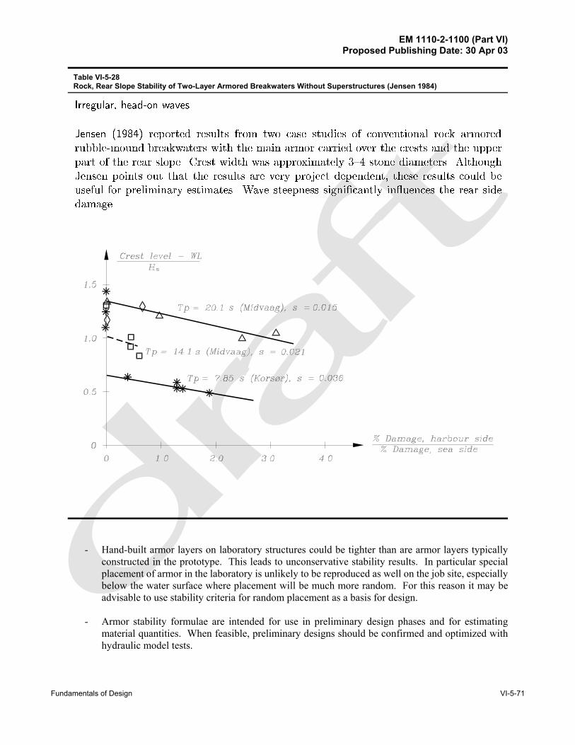
Jensen ������ reported results from two case studies of conventional rock armored
rubble�mound breakwaters with the main armor carried over the crests and the upper
part of the rear slope� Crest width was approximately ��� stone diameters� Although
Jensen points out that the results are very project dependent� these results could be
useful for preliminary estimates� Wave steepness signi�cantly in�uences the rear side
damage�
�
Table VI-5-28Rock, Rear Slope Stability of Two-Layer Armored Breakwaters Without Superstructures (Jensen 1984)
- Hand-built armor layers on laboratory structures could be tighter than are armor layers typicallyconstructed in the prototype. This leads to unconservative stability results. In particular specialplacement of armor in the laboratory is unlikely to be reproduced as well on the job site, especiallybelow the water surface where placement will be much more random. For this reason it may beadvisable to use stability criteria for random placement as a basis for design.
- Armor stability formulae are intended for use in preliminary design phases and for estimatingmaterial quantities. When feasible, preliminary designs should be confirmed and optimized withhydraulic model tests.
EM 1110-2-1100 (Part VI)Proposed Publishing Date: 30 Apr 03
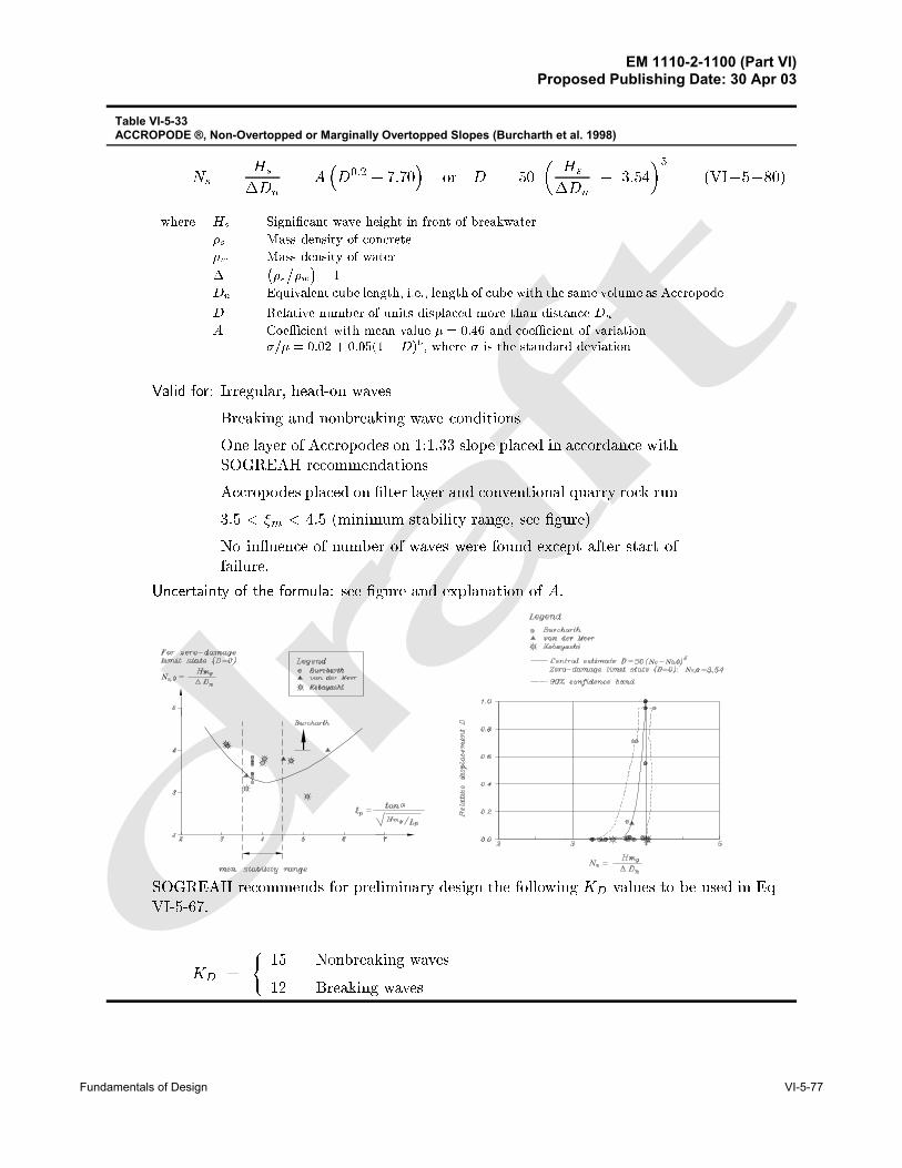
Table VI-5-33ACCROPODE ®, Non-Overtopped or Marginally Overtopped Slopes (Burcharth et al. 1998)
EM 1110-2-1100 (Part VI)Proposed Publishing Date: 30 Apr 03
VI-5-78 Fundamentals of Design
Irregular, head-on waves
(VI-5-81)H∆Dn50
' (KD cotα)1/3 or M50 'ρc H 3
KD (ρc
ρw
& 1)3 cotα
where H Characteristic wave height (Hs )Dn50 Equivalent length of cube having same mass as Core-Loc, D50 = (M50 /ρs)1/3 M50 Mass of Core-Loc armor unit, M50 = ρs (Dn50)3
ρc Mass density of concrete ρw Mass density of water∆ (ρs /ρw) - 1α Slope angleKD Stability coefficient
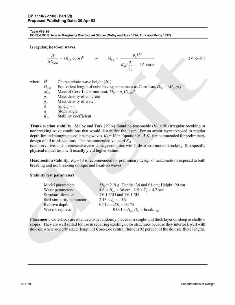
Trunk section stability. Melby and Turk (1994) found no reasonable (KD < 50) irregular breaking ornonbreaking wave conditions that would destabilize the layer. For an armor layer exposed to regulardepth-limited plunging to collapsing waves, KD = 16 in Equation VI-5-81 is recommended for preliminarydesign of all trunk sections. The recommended value of KDis conservative, and it represents a zero-damage condition with little to no armor unit rocking. Site specificphysical model tests will usually yield higher values.
Head section stability. KD = 13 is recommended for preliminary design of head sections exposed to bothbreaking and nonbreaking oblique and head-on waves.
Placement. Core-Locs are intended to be randomly placed in a single-unit thick layer on steep or shallowslopes. They are well suited for use in repairing existing dolos structures because they interlock well withdolosse when properly sized (length of Core-Loc central flume is 92 percent of the dolosse fluke length).
Table VI-5-34CORE-LOC ®, Non or Marginally Overtopped Slopes (Melby and Turk 1994; Turk and Melby 1997)
EM 1110-2-1100 (Part VI)Proposed Publishing Date: 30 Apr 03
Table VI-5-35Tetrapods, Horizontally Composite Breakwaters (Hanzawa et al. 1996)
EM 1110-2-1100 (Part VI)Proposed Publishing Date: 30 Apr 03
VI-5-80 Fundamentals of Design
Regular, head-on waves
(VI-5-83)H∆Dn50
' (KD cotα)1/3 or M50 'ρs H 3
KD (ρs
ρw
& 1)3 cotα
where H Characteristic wave height (Hs )Dn50 Equivalent cube length of median rock M50 Median mass of stone armor unit, M50 = ρs (Dn50)3
ρs Mass density of stoneρw Mass density of water∆ (ρs /ρw) - 1α Slope angleKD Stability coefficient
Trunk section stability.
KD-values by Shore Protection Manual, H = H1/10, 0% to 5% damage
Placement Layers Breakingwaves1
Nonbreakingwaves2
Slope anglecot α
Random 2 9.0 10.0 1.5 - 3.0
Pattern-placed 1 12.0 15.0 (not given)
1 Depth-limited breaking with waves breaking in front of and on the armor slope.2 No depth-limited breaking occurs in front of the armor slope.
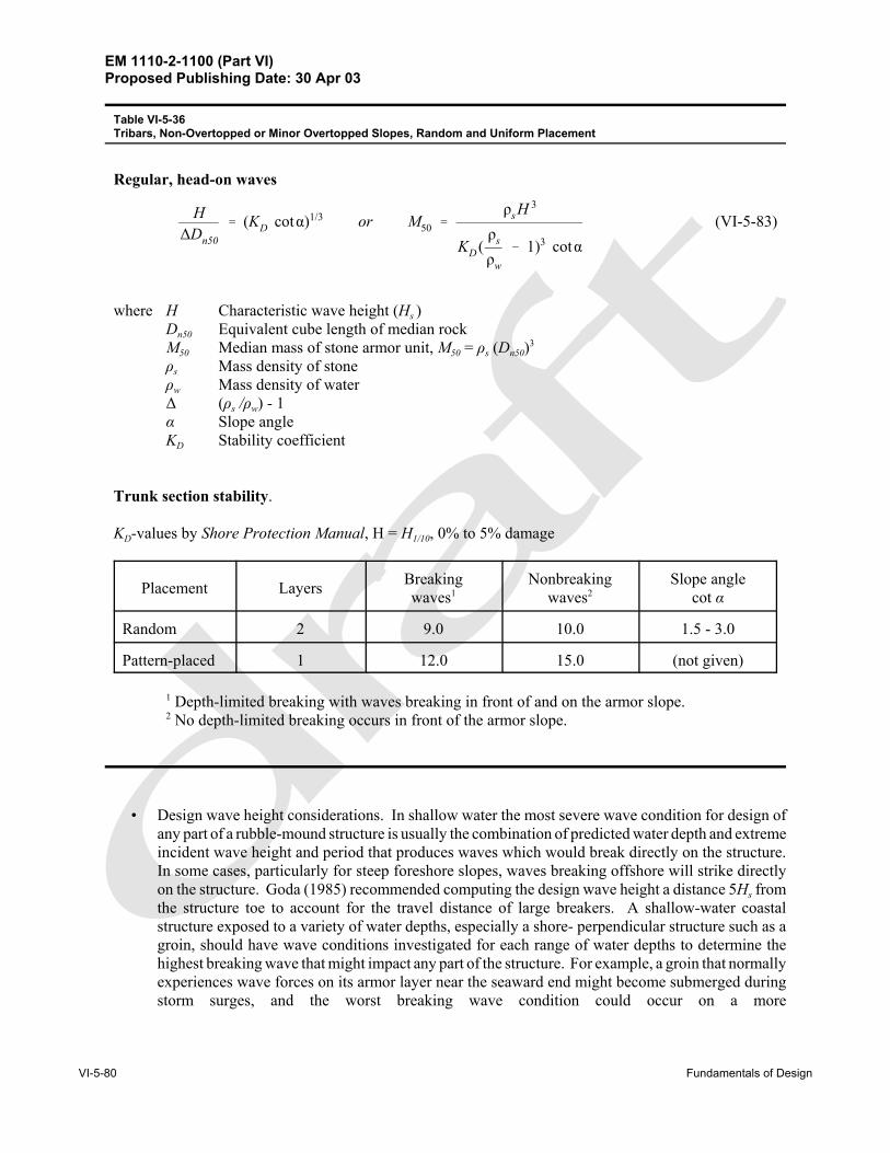
Table VI-5-36Tribars, Non-Overtopped or Minor Overtopped Slopes, Random and Uniform Placement
• Design wave height considerations. In shallow water the most severe wave condition for design ofany part of a rubble-mound structure is usually the combination of predicted water depth and extremeincident wave height and period that produces waves which would break directly on the structure.In some cases, particularly for steep foreshore slopes, waves breaking offshore will strike directlyon the structure. Goda (1985) recommended computing the design wave height a distance 5Hs fromthe structure toe to account for the travel distance of large breakers. A shallow-water coastalstructure exposed to a variety of water depths, especially a shore- perpendicular structure such as agroin, should have wave conditions investigated for each range of water depths to determine thehighest breaking wave that might impact any part of the structure. For example, a groin that normallyexperiences wave forces on its armor layer near the seaward end might become submerged duringstorm surges, and the worst breaking wave condition could occur on a more
EM 1110-2-1100 (Part VI)Proposed Publishing Date: 30 Apr 03
Fundamentals of Design VI-5-81
Figure VI-5-37. Illustration of critical areas for damage to armor layers in the round head(Burcharth 1993)
landward portion of the groin. The effect of oblique wave approach on armor layer stability has notyet been sufficiently quantified. Tests in the European Marine Science and Technology (MAST)program seemed to indicate relatively little reduction in damage for rock armored slopes subjectedto oblique wave approach angles up to 60 deg compared to waves of normal incidence (Allsop 1995).The stability of any rubble-mound structure exposed to oblique wave attack should be confirmed withphysical model tests.
(6) Structure head section stability.
(a) Under similar wave conditions the round head of a rubble-mound structure normally sustains moreextensive and more frequent damage than the structure trunk. One reason is very high cone-overflowvelocities, sometimes enhanced in certain areas by wave refraction. Another reason is the reduced supportfrom neighboring units in the direction of wave overflow on the lee side of the cone as shown inFigure VI-5-37. This figure also illustrates the position of the most critical area for armor layer instability.The toe within the same area is also vulnerable to damage in shallow-water situations, and a toe failure willoften trigger failure of the armor layer see Part VI-5-6-b-2, “Scour at sloping structures.”
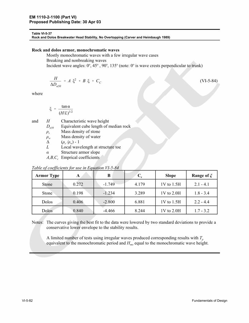
(b) Table VI-5-37 presents stability criteria for stone and dolos rubble-mound structure heads subjectedto breaking and nonbreaking waves without overtopping, and Table VI-5-38 gives stability criteria fortetrapod and tribar concrete armor units.
EM 1110-2-1100 (Part VI)Proposed Publishing Date: 30 Apr 03
VI-5-82 Fundamentals of Design
Rock and dolos armor, monochromatic waves Mostly monochromatic waves with a few irregular wave casesBreaking and nonbreaking wavesIncident wave angles: 0o, 45o , 90o, 135o (note: 0o is wave crests perpendicular to trunk)
(VI-5-84)H∆Dn50
' A ξ2 % B ξ % CC
where
ξ 'tanα
(H/L)1/2
and H Characteristic wave heightDn50 Equivalent cube length of median rock ρs Mass density of stoneρw Mass density of water∆ (ρs /ρw) - 1L Local wavelength at structure toeα Structure armor slopeA,B,Cc Emprical coefficients
Table of coefficients for use in Equation VI-5-84
Armor Type A B Cc Slope Range of ξ
Stone 0.272 -1.749 4.179 1V to 1.5H 2.1 - 4.1
Stone 0.198 -1.234 3.289 1V to 2.0H 1.8 - 3.4
Dolos 0.406 -2.800 6.881 1V to 1.5H 2.2 - 4.4
Dolos 0.840 -4.466 8.244 1V to 2.0H 1.7 - 3.2
Notes: The curves giving the best fit to the data were lowered by two standard deviations to provide aconservative lower envelope to the stability results.
A limited number of tests using irregular waves produced corresponding results with Tpequivalent to the monochromatic period and Hmo equal to the monochromatic wave height.
Table VI-5-37Rock and Dolos Breakwater Head Stability, No Overtopping (Carver and Heimbaugh 1989)
EM 1110-2-1100 (Part VI)Proposed Publishing Date: 30 Apr 03
Fundamentals of Design VI-5-83
Regular, head-on waves
(VI-5-85)H∆Dn50
' (KD cotα)1/3 or M50 'ρs H 3
KD (ρs
ρw
& 1)3 cotα
where H Characteristic wave height (Hs )Dn50 Equivalent cube length of median rock M50 Median mass of stone armor unit, M50 = ρs (Dn50)3
ρs Mass density of stoneρw Mass density of water∆ (ρs /ρw) - 1α Slope angleKD Stability coefficient
Head Section Stability.
KD-values by Shore Protection Manual (1984), H = H1/10, 0 percent to 5 percent damage
Armor Unit Placement Layers BreakingWaves1
NonbreakingWaves2
Slope Anglecot α
Tetrapod Random 2
5.03 6.0 1.5
4.5 5.5 2.0
3.5 4.0 3.0
Tribar Random 2
8.3 9.0 1.5
7.8 8.5 2.0
6.0 6.5 3.0
Tribar Pattern 1 7.5 9.5 (not given)
1 Depth-limited breaking with waves breaking in front of and on the armor slope.2 No depth-limited breaking occurs in front of the armor slope.3 KD values shown in italics are unsupported by tests results and are provided only for preliminary design purposes.
Table VI-5-38Tetrapod and Tribar Breakwater Head Section Stability, No Overtopping