Original Design Sizes 210 & 215 GEN 2 Design Sizes 50, 100 & 180 Individual Clutch or Brake Module Combine to Comprise a Clutch, Brake or Clutch/Brake Combination Electro Modules are individual clutch or brake units which are assembled together to comprise a clutch, brake, or clutch/brake combination. Electro Modules can be bolted directly to a NEMA C-face motor or reducer or they can be base mounted for stand alone operation. Electro Modules offer the ultimate in clutch/brake convenience. They are easy and quick to install and require no lubrication or maintenance for life. Bolt-it-down and wire-it-up ... it’s ready to go! • Modular design flexibility • 1/4 to 7-1/2 HP at 1800 RPM • Outstanding controllability • Fast cycling • Smooth starts and stops • Accurate • Bidirectional • Consistent performance • Complete control capability Selection Flexibility Clutch/Brake Combination A wide range of module combinations for use with motors, reducers and other standard power transmission components is available. The flexibility of Electro Module enables you to pick the exact combination of function and design. Power-On Applications Electro Modules for power-on applications are purchased as individual clutches and brakes to be assembled for C-face, flange, or base mounting applications. Power-Off (Electrically Released) Applications Electrically released operation is the primary feature of power-off Electro Module brakes. They can be used as brakes, motor brakes and in combination with clutches. See page 106 for complete information. Selection The correct size can be determined from easy-to-use selection charts based on NEMA frame sizes or horsepower and shaft speed. Examples show the right way to order the Electro Module required. Controls Warner Electric controls assure that you get the maximum performance from your Electro Module. See page 201. 24 Warner Electric 800-825-6544 P-1234-WE 4/11 EM Series Electro Module CALL NOW 800-985-6929 http://www.automatedpt.com Email: [email protected]CALL NOW 800-985-6929 http://www.automatedpt.com Email: [email protected]
Transcript
Original DesignSizes 210 & 215
GEN 2 DesignSizes 50, 100 & 180
Individual Clutch or Brake Module Combine to Comprise a Clutch, Brake or Clutch/Brake Combination
Electro Modules are individual clutch orbrake units which are assembledtogether to comprise a clutch, brake, orclutch/brake combination. ElectroModules can be bolted directly to aNEMA C-face motor or reducer or theycan be base mounted for stand aloneoperation. Electro Modules offer theultimate in clutch/brake convenience.They are easy and quick to install andrequire no lubrication or maintenance for life.
Bolt-it-down and wire-it-up ... it’s ready to go!
• Modular design flexibility
• 1/4 to 7-1/2 HP at 1800 RPM
• Outstanding controllability
• Fast cycling
• Smooth starts and stops
• Accurate
• Bidirectional
• Consistent performance
• Complete control capability
Selection Flexibility Clutch/BrakeCombinationA wide range of module combinations foruse with motors, reducers and otherstandard power transmissioncomponents is available. The flexibility ofElectro Module enables you to pick theexact combination of function anddesign.
Power-On ApplicationsElectro Modules for power-onapplications are purchased as individualclutches and brakes to be assembled forC-face, flange, or base mountingapplications.
Power-Off (Electrically Released)ApplicationsElectrically released operation is theprimary feature of power-off ElectroModule brakes. They can be used asbrakes, motor brakes and incombination with clutches. See page106 for complete information.
SelectionThe correct size can be determined fromeasy-to-use selection charts based onNEMA frame sizes or horsepower andshaft speed. Examples show the rightway to order the Electro Modulerequired.
ControlsWarner Electric controls assure that youget the maximum performance from yourElectro Module. See page 201.
24 Warner Electric 800-825-6544 P-1234-WE 4/11
EM Series Electro Module
CALL NOW 800-985-6929 http://www.automatedpt.com Email: [email protected]
CALL NOW 800-985-6929 http://www.automatedpt.com Email: [email protected]
EM Series Electro Module
P-1234-WE 4/11 Warner Electric 800-825-6544 25
Modular Components
20/30-BBrake/Input Clutch–Base MountedStand alone units attach with pulleys,sprockets, etc. See page 37.
20/30Brake/Input ClutchUse for clutch/brake applications.Features dual C-faces and shafts. Inputfrom parallel drive or coupling. Outputto reducer. Basic components are field,rotor, 2 armatures and power-onmagnet. See page 37.
10/20Motor Clutch/BrakeUse for clutch/brake applications.Hollow bore input. Shaft on output side.Basic components are field, rotor, 2armatures and power-on magnet. Seepage 35.
Clutch/Brake Combinations
30/40-BInput Clutch/Output Clutch–Base MountedBase mounting allows the clutch unitsto be utilized as a separate drive unit.Attach with pulleys, sprockets, etc. Seepage 38.
30/40Input Clutch/Output ClutchUse for clutch only applications.Features dual C-faces and shafts. Unitinput from parallel drive or coupling.Output to reducer. Basic componentsare field, rotor and armature. See page 38.
10/40Motor Clutch/Output ClutchUse for clutch only applications. Hashollow bore input for mounting directlyto C-face motors. Shaft and C-face onoutput side of unit accommodatesreducer, parallel drive or coupling.Basic components are field, rotor andarmature. See page 36.
Clutch Combinations
20 BrakeBolts directly to C-face components. See page 31.
20MB Motor BrakeDoes not have a shaft. Has end cap. See page 32 .
Clutch Modules
Brake Modules
10 Motor ClutchFan cooled for long life and consistentperformance. See page 30.
40 Output ClutchAutogap™ automatically adjust armaturefor wear. Does not have a coil – use incombination with a 10 Motor Clutch or 30Input Clutch module. See page 34.
CALL NOW 800-985-6929 http://www.automatedpt.com Email: [email protected]
CALL NOW 800-985-6929 http://www.automatedpt.com Email: [email protected]
Electro Module clutch or brake units maybe mounted directly to NEMA C-facemotors and reducers, or can be basemounted.
Based on the NEMA C-face framesize of the prime mover, select thecorrect clutch or brake module sizefrom the Frame Size Selection chart.Size 100 houses the components ofthe size 180 in a size 50 frame, whilesize 215 incorporates size 210components.
1. Select Configurationa. NEMA C-face Mounting
2. Determine TechnicalRequirements
Technical considerations for sizing and selection are torque and heatdissipation. Each merits carefulconsideration, especially heatdissipation as over time, use inexcessive temperature environmentswill have an adverse effect on bearinglife and coil wire insulation integrity.
Compare the calculated torquerequirement with the average dynamictorque ratings. Select a unit withadequate torque. If the unit selected on torque is different than the unitselected based on heat, select thelarger size unit.
b. Base Mounting
Electro Module assemblies may bemounted as separate drive unitsdriven from the prime mover by V-belts, chain and sprockets,couplings, timing belts and otherstandard power transmissioncomponents.
Select the correct size module fromthe Horsepower vs. Shaft Speed chartby determining the motor horsepowerand RPM at the module location. Thecorrect size Electro Module is shown at the intersection of the HP and operating speed.
For additional sizing information, referto the technical sizing procedure (step 2).
* For 56C/48Y Frame motors 3/4 HP and smaller the UM-100 size may be used where extended life isdesirable.
** UM-100 size is recommended for motors 1 HP and larger.
CALL NOW 800-985-6929 http://www.automatedpt.com Email: [email protected]
CALL NOW 800-985-6929 http://www.automatedpt.com Email: [email protected]
a. Heat Dissipation SizingFriction surfaces slip during the initialperiod of engagement and, as a result,heat is generated. The clutch/brakeselected must have a heat dissipationrating greater than the heat generatedby the application. Therefore, in highinertia or high cycle rate applications, it is necessary to check the heatdissipation carefully. Inertia, speed andcycle rate are the required parameters.
Heat dissipation requirement iscalculated as follows:
E = 1.7 x WR2 x (N/100)2 x F
where:
E = Heat (lb. ft./min.)
WR2 = Total reflected inertia at theclutch/brake shaft. Include theclutch/brake output inertia. (lb.ft.2)
N = Speed in revolutions per minute(RPM)
F = Cycle rate in cycles per minute(CPM)
Compare the calculated heat generatedin the application to the unit ratingsusing the heat dissipation curves.Select the appropriate unit that hasadequate heat dissipation ability.
b. Torque SizingFor most applications, the correct sizeclutch/brake can be selected from theHorsepower vs. Shaft Speed chart.
Determine the motor horsepower andthe RPM at the clutch/brake. Thecorrect size unit is shown at theintersection of horsepower and shaftspeed.
If the static torque requirements areknown, refer to the Specifications Tableto select a unit.
For some applications, the torquerequirement is determined by the timeallowed to accelerate and deceleratethe load. (This time is generallyspecified in milliseconds.) For theseapplications, it is necessary todetermine the torque requirementbased on load inertia and the timeallowed for engagement.
The torque requirements are calculatedas follows:
T = (WR2 x N) / (308 x t)
where:
T = Average Dynamic Torque (lb. ft.)
WR2 = Total reflected inertia at theclutch/brake shaft. Include the clutch/brake output inertia. (lb. ft.2)
N = Speed in revolutions per minute(RPM)
t = Time allowed for the engagement(sec)
CALL NOW 800-985-6929 http://www.automatedpt.com Email: [email protected]
CALL NOW 800-985-6929 http://www.automatedpt.com Email: [email protected]
EM Series Electro Module
28 Warner Electric 800-825-6544 P-1234-WE 4/11
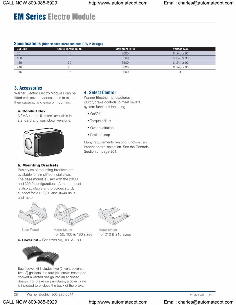
Specifications (Blue shaded areas indicate GEN 2 design)EM Size Static Torque lb. ft. Maximum RPM Voltage D.C.
50 16 3600 6, 24, or 90100 30 3600 6, 24, or 90180 30 3600 6, 24, or 90210 95 3600 6, 24, or 90215 95 3600 90
3. AccessoriesWarner Electric Electro Modules can befitted with several accessories to extendtheir capacity and ease of mounting.
a. Conduit BoxNEMA 4 and UL listed, available instandard and washdown versions.
b. Mounting BracketsTwo styles of mounting brackets areavailable for simplified installation. The base mount is used with the 20/30and 30/40 configurations. A motor mountis also available and provides sturdysupport for 20, 10/20 and 10/40 unitsand motor.
c. Cover Kit – For sizes 50, 100 & 180
4. Select Control Warner Electric manufacturesclutch/brake controls to meet severalsystem functions including:
• On/Off
• Torque adjust
• Over excitation
• Position loop
Many requirements beyond function canimpact control selection. See the ControlsSection on page 201.
Each cover kit includes two (2) vent covers,two (2) gaskets and four (4) screws needed toconvert a vented design into an encloseddesign. For brake only modules, a cover plateis included to enclose the back of the brake.
Base Mount Motor MountFor 50, 100 & 180 sizes
Motor MountFor 210 & 215 sizes
CALL NOW 800-985-6929 http://www.automatedpt.com Email: [email protected]
CALL NOW 800-985-6929 http://www.automatedpt.com Email: [email protected]
EM Series Electro Module
P-1234-WE 4/11 Warner Electric 800-825-6544 29
Ordering Information
Part Numbers(Blue shaded areas indicate GEN 2 design)
Model No. Voltage D.C. GEN 2 Part No. Original Part No.
How to OrderMotor or Reducer MountedSimply combine the size number with the configuration of themodular combination from page 25. Specify voltage. Seechart for specific part numbers. Power-off brake ElectroModules are found on page 106. Order optional conduit box ifdesired.
ExampleEM-180 10 – 20 90 Volt
BrakeMotor Clutch
Size
Base MountedSimply combine the size number with the configuration of themodular combination from page 25. Specify voltage. Seechart for specific part numbers. Power-off brake ElectroModules are found on page 106. Order optional conduit box ifdesired.
ExampleEM-180 20 – 30 - B 90 Volt
BaseInput Clutch
BrakeSize
Select Appropriate Power Supply/Control. See the ControlsSection beginning on page 201.
Only 50, 100, and 180 sizes of the models listed will be converted to the new GEN 2 design. 210 and 215 sizes will continue to be offered in the original design and will not be converted.
CALL NOW 800-985-6929 http://www.automatedpt.com Email: [email protected]
CALL NOW 800-985-6929 http://www.automatedpt.com Email: [email protected]
EM Series Electro Module
30 Warner Electric 800-825-6544 P-1234-WE 4/11
Specifications (Blue shaded areas indicate GEN 2 design)Model Size Voltage DC Static Torque lb. ft. Max. RPM Inertia–WR2 (lb.ft.2) Weight (lbs) NEMA Frame Size
* For 56C/48Y Frame motors 3/4 HP and smaller the UM-100 size may be used where extended life is desirable.** UM-100 size is recommended for motors 1 HP and larger.
For standard NEMA frame dimensions, see page 187.
Dimensions (Blue shaded areas indicate GEN 2 design)Size A B C D E F G
50 1.555 .625 .780 6.750 0° 36 3/16 x 3/16100 1.555 .625 .780 6.750 0° 36 3/16 x 3/16180 1.555 .875 .780 6.750 0° 36 3/16 x 3/16210 1.313 1.125 .700 9.250 65° 36 1/4 x 1/4
FE1/2"-NPT
øD
G
C
A
øB
10 Motor Clutch Module
Only 50, 100, and 180 sizes of the models listed will be converted to the new GEN 2 design. 210 size will continue to be offered in the original design and will not be converted.
CALL NOW 800-985-6929 http://www.automatedpt.com Email: [email protected]
CALL NOW 800-985-6929 http://www.automatedpt.com Email: [email protected]
EM Series Electro Module
P-1234-WE 4/11 Warner Electric 800-825-6544 31
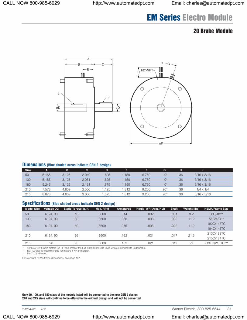
20 Brake Module
Dimensions (Blue shaded areas indicate GEN 2 design)Size A B C D E F G H J
Specifications (Blue shaded areas indicate GEN 2 design)Model Size Voltage DC Static Torque lb. ft. Max. RPM Armatures Inertia–WR2 Arm. Hub Shaft Weight (lbs) NEMA Frame Size
215 90 95 3600 .162 .021 .019 22 213TC/215TC**** For 56C/48Y Frame motors 3/4 HP and smaller the EM-100 size may be used where extended life is desirable.** EM-100 size is recommended for motors 1 HP and larger.*** For 7-1/2 HP max.
For standard NEMA frame dimensions, see page 187.
G
H1/2"-NPT
øF
J
B
øD
E
A
C
J
øD
Only 50, 100, and 180 sizes of the models listed will be converted to the new GEN 2 design. 210 and 215 sizes will continue to be offered in the original design and will not be converted.
CALL NOW 800-985-6929 http://www.automatedpt.com Email: [email protected]
CALL NOW 800-985-6929 http://www.automatedpt.com Email: [email protected]
EM Series Electro Module
32 Warner Electric 800-825-6544 P-1234-WE 4/11
20MB Motor Brake Module
Dimensions (Blue shaded areas indicate GEN 2 design)Size A B C D E F G H
Specifications (Blue shaded areas indicate GEN 2 design)Model Size Voltage DC Static Torque lb. ft. Max. RPM Armatures Inertia–WR2 Arm. Hub Input Hub Weight (lbs) NEMA Frame Size
*For 56C/48Y Frame motors 3/4 HP and smaller the EM-100 size may be used where extended life is desirable.
For standard NEMA frame dimensions, see page 187.
G
H1/2"-NPT
øE
F
B
øD
A
C
Only 50 and 180 sizes of the models listed will be converted to the new GEN 2 design. 210 size will continue to be offered in the original design and will not be converted.
CALL NOW 800-985-6929 http://www.automatedpt.com Email: [email protected]
CALL NOW 800-985-6929 http://www.automatedpt.com Email: [email protected]
EM Series Electro Module
P-1234-WE 4/11 Warner Electric 800-825-6544 33
30 Input Clutch Module
Dimensions (Blue shaded areas indicate GEN 2 design)Size A B C D E F G H J
* For 56C/48Y Frame motors 3/4 HP and smaller the EM-100 size may be used where extended life is desirable.** EM-100 size is recommended for motors 1 HP and larger.
For standard NEMA frame dimensions, see page 187.
øF
HG1/2"-NPT
A
C B
øD
J
E
Only 50, 100, and 180 sizes of the models listed will be converted to the new GEN 2 design. 210 size will continue to be offered in the original design and will not be converted.
CALL NOW 800-985-6929 http://www.automatedpt.com Email: [email protected]
CALL NOW 800-985-6929 http://www.automatedpt.com Email: [email protected]
EM Series Electro Module
34 Warner Electric 800-825-6544 P-1234-WE 4/11
Specifications (Blue shaded areas indicate GEN 2 design)Inertia–WR2
Model Size Voltage DC Static Torque lb. ft. Max. RPM Armatures Arm. Hub Shaft Weight (lbs) NEMA Frame Size
* For 56C/48Y Frame motors 3/4 HP and smaller the EM-100 size may be used where extended life is desirable.** EM-100 size is recommended for motors 1 HP and larger.
For standard NEMA frame dimensions, see page 187.
Dimensions (Blue shaded areas indicate GEN 2 design)Size A B C D E F
50 5.165 3.125 2.040 .625 6.750 3/16 x 3/16100 5.186 3.125 2.061 .625 6.750 3/16 x 3/16180 5.246 3.125 2.121 .875 6.750 3/16 x 3/16210 7.578 4.609 2.500 1.125 9.250 1/4 x 1/4
øEB
A
C
øD
F
40 Output Clutch Module
Only 50, 100, and 180 sizes of the models listed will be converted to the new GEN 2 design. 210 size will continue to be offered in the original design and will not be converted.
CALL NOW 800-985-6929 http://www.automatedpt.com Email: [email protected]
CALL NOW 800-985-6929 http://www.automatedpt.com Email: [email protected]
EM Series Electro Module
P-1234-WE 4/11 Warner Electric 800-825-6544 35
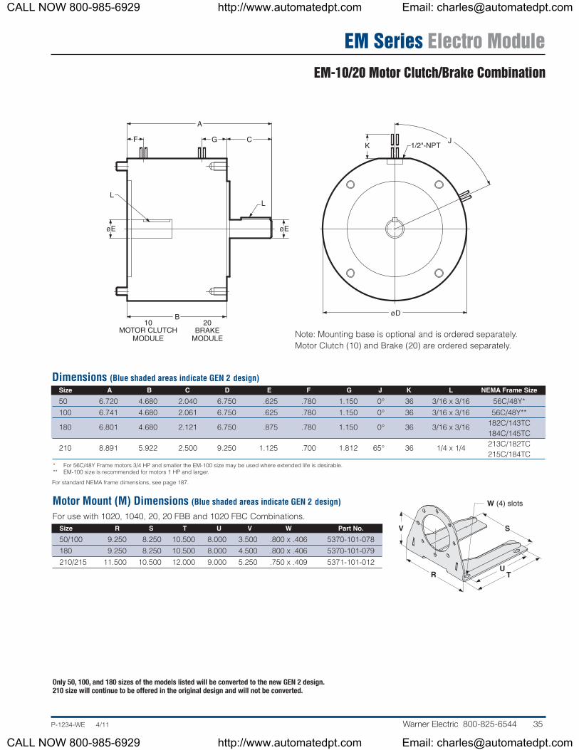
EM-10/20 Motor Clutch/Brake Combination
Dimensions (Blue shaded areas indicate GEN 2 design)Size A B C D E F G J K L NEMA Frame Size
* For 56C/48Y Frame motors 3/4 HP and smaller the EM-100 size may be used where extended life is desirable.** EM-100 size is recommended for motors 1 HP and larger.
For standard NEMA frame dimensions, see page 187.
Note: Mounting base is optional and is ordered separately.Motor Clutch (10) and Brake (20) are ordered separately.
Motor Mount (M) Dimensions (Blue shaded areas indicate GEN 2 design)
For use with 1020, 1040, 20, 20 FBB and 1020 FBC Combinations.Size R S T U V W Part No.
50/100 9.250 8.250 10.500 8.000 3.500 .800 x .406 5370-101-078180 9.250 8.250 10.500 8.000 4.500 .800 x .406 5370-101-079210/215 11.500 10.500 12.000 9.000 5.250 .750 x .409 5371-101-012
Only 50, 100, and 180 sizes of the models listed will be converted to the new GEN 2 design. 210 size will continue to be offered in the original design and will not be converted.
1/2"-NPTJ
K
øD10
MOTOR CLUTCHMODULE
20BRAKE
MODULE
B
L
GF
A
C
øE
L
øE
R
V
UT
S
W (4) slots
CALL NOW 800-985-6929 http://www.automatedpt.com Email: [email protected]
CALL NOW 800-985-6929 http://www.automatedpt.com Email: [email protected]
EM Series Electro Module
36 Warner Electric 800-825-6544 P-1234-WE 4/11
Motor Mount (M) Dimensions (Blue shaded areas indicate GEN 2 design)
Note: Mounting base is optional and is ordered separately.Motor Clutch (10) and Output Clutch (40) are ordered separately.
For use with 1020, 1040, 20, 20 FBB and 1020 FBC Combinations.Size R S T U V W Part No.
50/100 9.250 8.250 10.500 8.000 3.500 .800 x .406 5370-101-078180 9.250 8.250 10.500 8.000 4.500 .800 x .406 5370-101-079210/215 11.500 10.500 12.000 9.000 5.250 .750 x .409 5371-101-012
EM-10/40 Motor Clutch/Output Clutch Combination
Only 50, 100, and 180 sizes of the models listed will be converted to the new GEN 2 design. 210 size will continue to be offered in the original design and will not be converted.
1/2"-NPT JK
øDB
L
GF
A
C
øE
L
40OUTPUT CLUTCH
MODULEMOTOR CLUTCH
MODULE
10
øE
R
V
UT
S
W (4) slots
Dimensions (Blue shaded areas indicate GEN 2 design)Size A B C D E F G J K L NEMA Frame Size
* For 56C/48Y Frame motors 3/4 HP and smaller the EM-100 size may be used where extended life is desirable.** EM-100 size is recommended for motors 1 HP and larger.
For standard NEMA frame dimensions, see page 187.
CALL NOW 800-985-6929 http://www.automatedpt.com Email: [email protected]
CALL NOW 800-985-6929 http://www.automatedpt.com Email: [email protected]
EM Series Electro Module
P-1234-WE 4/11 Warner Electric 800-825-6544 37
EM-20/30 Brake/Input Clutch CombinationEM-20/30-B Brake/Input Clutch Combination – Base Mounted
Dimensions (Blue shaded areas indicate GEN 2 design)Size A B C D E F G H J K L
Note: Mounting base is optional and is ordered separately.Input Clutch (30) module and Brake Module (20) are ordered separately.
Only 50, 100, and 180 sizes of the models listed will be converted to the new GEN 2 design. 210 size will continue to be offered in the original design and will not be converted.
CALL NOW 800-985-6929 http://www.automatedpt.com Email: [email protected]
CALL NOW 800-985-6929 http://www.automatedpt.com Email: [email protected]
EM Series Electro Module
38 Warner Electric 800-825-6544 P-1234-WE 4/11
OPTIONALBASE MOUNT
J
S
T
U
V
K 1/2"-NPT
øHA
C
M
N
PR
B D
L
øE
L
F G
MODULEOUTPUT CLUTCH
40
MODULEINPUT CLUTCH
30
øE
Note: Mounting base is optional and is ordered separately. InputClutch (30) module and Output Clutch (40) are ordered separately.
Only 50, 100, and 180 sizes of the models listed will be converted to the new GEN 2 design. 210 size will continue to be offered in the original design and will not be converted.
CALL NOW 800-985-6929 http://www.automatedpt.com Email: [email protected]
CALL NOW 800-985-6929 http://www.automatedpt.com Email: [email protected]
Enclosed Electro Module
P-1234-WE 4/11 Warner Electric 800-825-6544 39
Contamination-Proof Design
Totally Enclosed VersionThe Enclosed Electro Module packagesthe hardworking components from EMproducts into a totally enclosedhousing. This rugged housing keepswear particles in and contaminants outand provides quiet operation. Whenenclosed, units are suitable for mostindustrial applications and tolerateinfrequent, light washing.
• Keeps contaminants out
• Keeps wear particles in
• Quiet operation
• Finned for heat dissipation
• UL listed when optional conduit box isinstalled
Clean, quiet, operation. Nothing can getin, nothing can get out. Enclosed designeliminates damage to the workingcomponents. Prevents friction wearparticles from escaping.
To convert any Gen 2 Electro Module 50, 100, and 180 sizes to an enclosed modelpurchase optional Cover Kit (part number 5370-101-076)(part number 5370-101-082 for brake only)
Enclosed Electro Module (10-20, 10-40, 20-30, 30-40) An optional cover kit (part number 5370-101-076) can be purchasedseparately to enclose the open vents in the housing. Each cover kitincludes two vent covers, two gaskets and four screws needed to converta vented Electro Module to an enclosed design (non-washdown).
Enclosed Electro Module-Brake Only (20 or 20MB) An optional cover kit (part number 5370-101-082) can be purchasedseparately to enclose the open vents in the housing and a cover plate to close off the back of the module. Each cover kit includes two ventcovers, two gaskets, four screws and one cover plate needed to converta vented Electro Module 20 to an enclosed design (non-washdown).
NOTE:
Enclosed option is not available for existing 210 & 215 size Electro Modules (EM)
900 1800 2700 3600
EUM-50
Maximum Speed 3600 RPM
0
2,000
4,000
6,000
8,000
10,000
12,000
Speed (RPM)
Hea
t D
issi
pat
ion
(ft.
lb./
min
.)
STANDARD
FAN COOLED
EUM-100/180
900 1800 2700 3600
Maximum Speed 3600 RPM
0
2,000
4,000
6,000
8,000
10,000
12,000
Speed (RPM)
Hea
t D
issi
pat
ion
(ft.
lb./
min
.)
STANDARD
FAN COOLED
CALL NOW 800-985-6929 http://www.automatedpt.com Email: [email protected]
CALL NOW 800-985-6929 http://www.automatedpt.com Email: [email protected]