68
INSTRUCTIONS FOR USE CAD LABSIDE all ceramic all you need
I N S T R U C T I O N S F O R U S E
CAD
L A B S I D E
all ceramic
all you need
2
Table of Contents
3 IPS e.max System – one system for every indication
4 Product Information
Material
Usage
Composition
Scientific Data
Block Concept
CAD/CAM Partners
9 Clinical steps, model preparation, CAD/CAM process
Overview of the Clinical Working Steps, Fabrication Process
Shade Determination — Tooth Shade, Shade of the Prepared Tooth
Preparation Guidelines
Model and Tooth Preparation
Layer Thicknesses
Design Guidelines for the Restoration
CAD/CAM Processing
18 Staining Technique
Finishing
Crystallization and Stain/Glaze Firing
– Option A: Crystallization and Stain/Glaze Firing in One Step with Glaze Paste
– Option B: Crystallization and Stain/Glaze Firing in One Step with Glaze Spray
– Option C: Crystallization and Separate Stain/Glaze Firing
35 Cut-Back Technique
Finishing and Preparation for Crystallization
Crystallization
Veneering with IPS e.max Ceram
45 Layering Technique
Finishing and Preparation for Crystallization
Crystallization
Veneering with IPS e.max Ceram
53 Seating and Follow-Up Care
Possibilities for Cementation
Preparing for Cementation
Care notes
56 General Information
Frequently Asked Questions
Table on Block Selection
Crystallization and Firing Parameters
CAD
CAD
PR
OD
UC
T
INF
OR
MA
TIO
N
INF
OR-
MA
TIO
N
PR
AC
TIC
AL
NO
TE
SO
NP
RO
CE
SS
ING
3
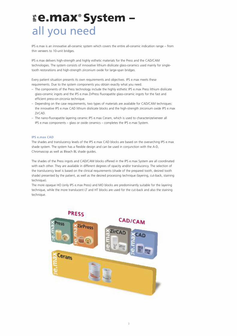
IPS e.max is an innovative all-ceramic system which covers the entire all-ceramic indication range – from
thin veneers to 10-unit bridges.
IPS e.max delivers high-strength and highly esthetic materials for the Press and the CAD/CAM
technologies. The system consists of innovative lithium disilicate glass-ceramics used mainly for single-
tooth restorations and high-strength zirconium oxide for large-span bridges.
Every patient situation presents its own requirements and objectives. IPS e.max meets these
requirements. Due to the system components you obtain exactly what you need.
– The components of the Press technology include the highly esthetic IPS e.max Press lithium disilicate
glass-ceramic ingots and the IPS e.max ZirPress fluorapatite glass-ceramic ingots for the fast and
efficient press-on-zirconia technique.
– Depending on the case requirements, two types of materials are available for CAD/CAM techniques:
the innovative IPS e.max CAD lithium disilicate blocks and the high-strength zirconium oxide IPS e.max
ZirCAD.
– The nano-fluorapatite layering ceramic IPS e.max Ceram, which is used to characterize/veneer all
IPS e.max components – glass or oxide ceramics – completes the IPS e.max System.
IPS e.max CAD
The shades and translucency levels of the IPS e.max CAD blocks are based on the overarching IPS e.max
shade system. The system has a flexible design and can be used in conjunction with the A-D,
Chromascop as well as Bleach BL shade guides.
The shades of the Press ingots and CAD/CAM blocks offered in the IPS e.max System are all coordinated
with each other. They are available in different degrees of opacity and/or translucency. The selection of
the translucency level is based on the clinical requirements (shade of the prepared tooth, desired tooth
shade) presented by the patient, as well as the desired processing technique (layering, cut-back, staining
technique).
The more opaque HO (only IPS e.max Press) and MO blocks are predominantly suitable for the layering
technique, while the more translucent LT and HT blocks are used for the cut-back and also the staining
technique.
e.max® System –all you need
IPS
4
e.max® CADProduct Information
IPS
Material
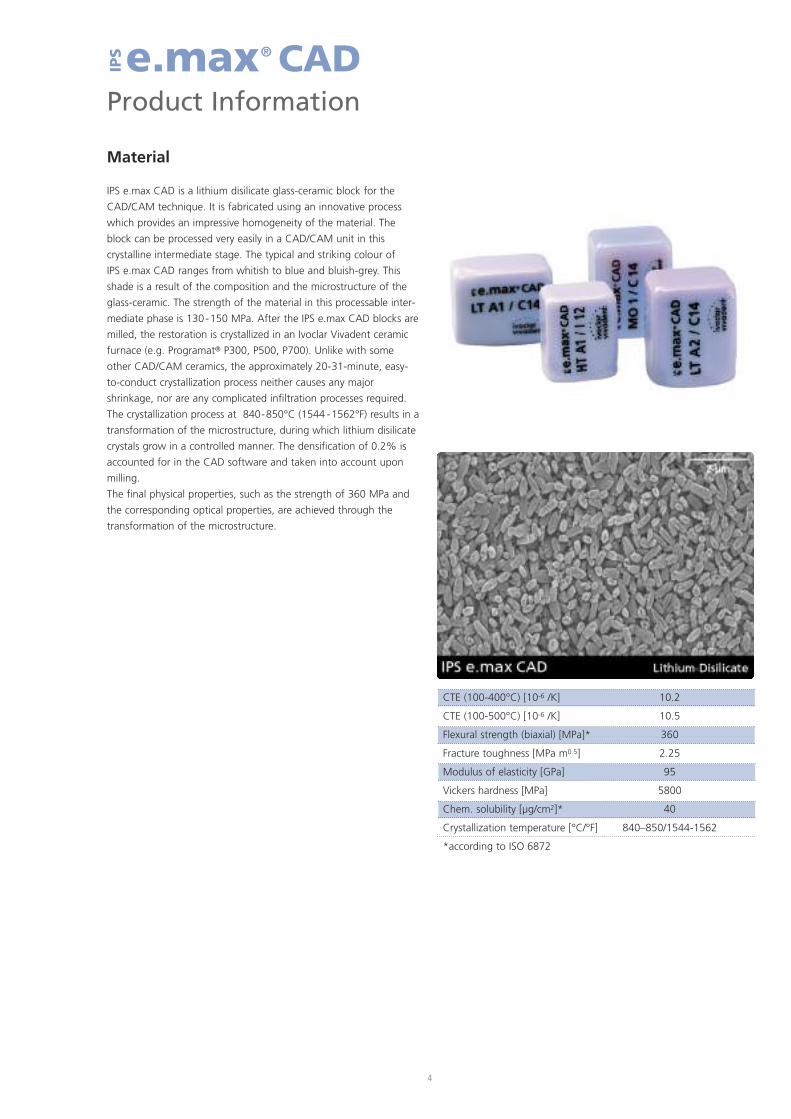
IPS e.max CAD is a lithium disilicate glass-ceramic block for the
CAD/CAM technique. It is fabricated using an innovative process
which provides an impressive homogeneity of the material. The
block can be processed very easily in a CAD/CAM unit in this
crystalline intermediate stage. The typical and striking colour of
IPS e.max CAD ranges from whitish to blue and bluish-grey. This
shade is a result of the composition and the microstructure of the
glass-ceramic. The strength of the material in this processable inter-
mediate phase is 130-150 MPa. After the IPS e.max CAD blocks are
milled, the restoration is crystallized in an Ivoclar Vivadent ceramic
furnace (e.g. Programat® P300, P500, P700). Unlike with some
other CAD/CAM ceramics, the approximately 20-31-minute, easy-
to-conduct crystallization process neither causes any major
shrinkage, nor are any complicated infiltration processes required.
The crystallization process at 840-850°C (1544 -1562°F) results in a
transformation of the microstructure, during which lithium disilicate
crystals grow in a controlled manner. The densification of 0.2% is
accounted for in the CAD software and taken into account upon
milling.
The final physical properties, such as the strength of 360 MPa and
the corresponding optical properties, are achieved through the
transformation of the microstructure.
CTE (100-400°C) [10-6 /K] 10.2
CTE (100-500°C) [10-6 /K] 10.5
Flexural strength (biaxial) [MPa]* 360
Fracture toughness [MPa m0.5] 2.25
Modulus of elasticity [GPa] 95
Vickers hardness [MPa] 5800
Chem. solubility [µg/cm2]* 40
Crystallization temperature [°C/°F] 840–850/1544-1562
*according to ISO 6872
5
Usage
Indications
– Veneers
– Inlays
– Onlays
– Partial crowns
– Crowns in the anterior and posterior region
– Implant superstructures for single-tooth restorations (anterior and
posterior region)
– Primary telescope crowns
Contraindications
– Full veneers on molar crowns
– Very deep sub gingival preparations
– Patients with substantially reduced residual dentition
– Bruxism
– Any other use not listed in the indications
Important processing restrictions
Failure to observe the following restrictions may compromise the
results achieved with IPS e.max CAD:
– The frameworks must not fall below the required minimum
thickness.
– Do not mill the blocks with non-compatible CAD/CAM systems.
– Crystallization must not be conducted in a ceramic furnace that
has not been approved and/or recommended.
– Crystallization must not be conducted in a ceramic furnace that
has no vacuum function.
– Crystallization must not be conducted in a ceramic furnace that
has not been calibrated.
– Crystallization must not be conducted in a high-temperature
furnace (e.g. Sintramat).
– Do not mix IPS e.max CAD Crystall./Glaze, Shades and Stains with
other dental ceramics (e.g. IPS e.max Ceram Glaze, Stains and
Essence).
– Do not layer with a veneering ceramic other than IPS e.max
Ceram.
Side effects
If the patient is known to be allergic to any of the components
of IPS e.max CAD, the material must not be used to fabricate
restorations.
Composition
– IPS e.max CAD Blocks
Components: SiO2
Additional contents: Li2O, K2O, MgO, Al2O3, P2O5 and other
oxides.
– IPS e.max CAD Crystall./Glaze, Shades and Stains
Components: oxides, glycols
– IPS e.max CAD Crystall./Glaze Spray
Components: oxides, propanol, propellant: isobutane
– IPS e.max CAD Crystall./Glaze Liquid
Components: butandiol
– IPS e.max CAD Crystall./Add-On
Components: oxides
– IPS e.max CAD Crystall./Add-On Liquid
components: water, propylene glycol, butandiol and chloride
– IPS Object Fix Putty / Flow
Components: oxides, water, thickening agent
– IPS Contrast Spray Labside
Components: pigment suspension in ethanol;
propellant: propane/butane mixture
– IPS Natural Die Material
Components: polymethacrylate, paraffin oil, SiO2 and copolymer
– IPS Natural Die Material Separator
Components: wax dissolved in hexane
– IPS Ceramic Etching Gel
Components: hydrofluoric acid (approx. 5%)
Warning
– Hexane is highly flammable and detrimental to health. Avoid con-
tact of the material with skin and eyes. Do not inhale vapours and
keep away from sources of ignition.
– Do not inhale ceramic dust during finishing – use exhaust air
discharge and mouth protection.
– IPS Ceramic Etching Gel contains hydrofluoric acid. Contact with
skin, eyes and clothing must be prevented at all costs, since the
material is extremely toxic and corrosive. The etching gel is
intended for professional use only and must not be applied intra-
orally (inside the mouth).
– IPS Contrast Spray Labside must not be used intra-orally.
6
Scientific Data
Further scientific data (e.g. strength, wear, biocompatibility) are contained in the “Scientific
Documentation IPS e.max CAD”. The Documentation also provides a set of studies that describe the
clinical performance of IPS e.max CAD.
This Scientific Documentation can be obtained from Ivoclar Vivadent.
For further information about all-ceramics and IPS e.max in general, please refer to the Ivoclar Vivadent
Reports No. 16 and No. 17.
Scientific Documentation
7
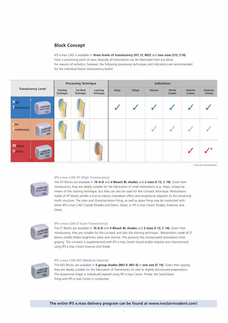
Block Concept
IPS e.max CAD is available in three levels of translucency (HT, LT, MO) and two sizes (I12, C14).
From a processing point of view, basically all restorations can be fabricated from any block.
For reasons of esthetics, however, the following processing techniques and indications are recommended
for the individual blocks (translucency levels):
IPS e.max CAD HT (High Translucency)
The HT Blocks are available in 16 A-D and 4 Bleach BL shades and 2 sizes (I 12, C 14). Given their
translucency, they are ideally suitable for the fabrication of small restorations (e.g. inlays, onlays) by
means of the staining technique, but they can also be used for the cut-back technique. Restorations
made of HT blocks exhibit a true-to-nature chameleon effect and exceptional adaption to the remaining
tooth structure. The stain and characterization firing, as well as glaze firing may be conducted with
either IPS e.max CAD Crystall./Shades and Stains, Glaze, or IPS e.max Ceram Shades, Essences and
Glaze.
IPS e.max CAD LT (Low Translucency)
The LT Blocks are available in 16 A-D and 4 Bleach BL shades and 2 sizes (I 12, C 14). Given their
translucency, they are suitable for the cut-back and also the staining technique. Restorations made of LT
blocks exhibit lifelike brightness value and chroma. This prevents the incorporated restorations from
graying. The cut-back is supplemented with IPS e.max Ceram Incisal and/or Impulse and characterized
using IPS e.max Ceram Essence and Shade.
IPS e.max CAD MO (Medium Opacity)
The MO Blocks are available in 5 group shades (MO 0-MO 4) in one size (C 14). Given their opacity,
they are ideally suitable for the fabrication of frameworks on vital or slightly discoloured preparations.
The anatomical shape is individually layered using ISP e.max Ceram. Finally, the Stain/Glaze
firing with IPS e.max Ceram is conducted.
Indications
Medium
Opacity
LowTranslucency
High
Translucency
CR %
StainingTechnique
Cut-BackTechnique
LayeringTechnique
Inlays Onlays Veneers PartialCrowns
AnteriorCrowns
PosteriorCrowns
Translucency Level
Processing Technique
� �
� � � � � �
� �
� �*
* up to the second premolar
The entire IPS e.max delivery program can be found at www.ivoclarvivadent.com!
8
CAD/CAM Partners
IPS e.max CAD can be processed with a system of the CAD/CAM partners. For questions regarding
the different systems, please contact the respective cooperation partners.
Information is available from:
Sirona Dental Systems GmbH
Fabrikstrasse 31
64625 Bensheim
Germany
E-mail: [email protected]
www.sirona.com
inLab® is a registered trademark of Sirona DentalSystems GmbH
Information is available from:
KaVo Dental GmbH
Bismarckring 39
88400 Biberach
Germany
E-mail:[email protected]
www.kavo-everest.com
Everest® is a registered trademark ofKaVo Dental GmbH
Information is available from:
Institut Straumann AG
Peter Merian-Weg 12
4052 Basel
Switzerland
E-mail:[email protected]
www.straumann.com
9
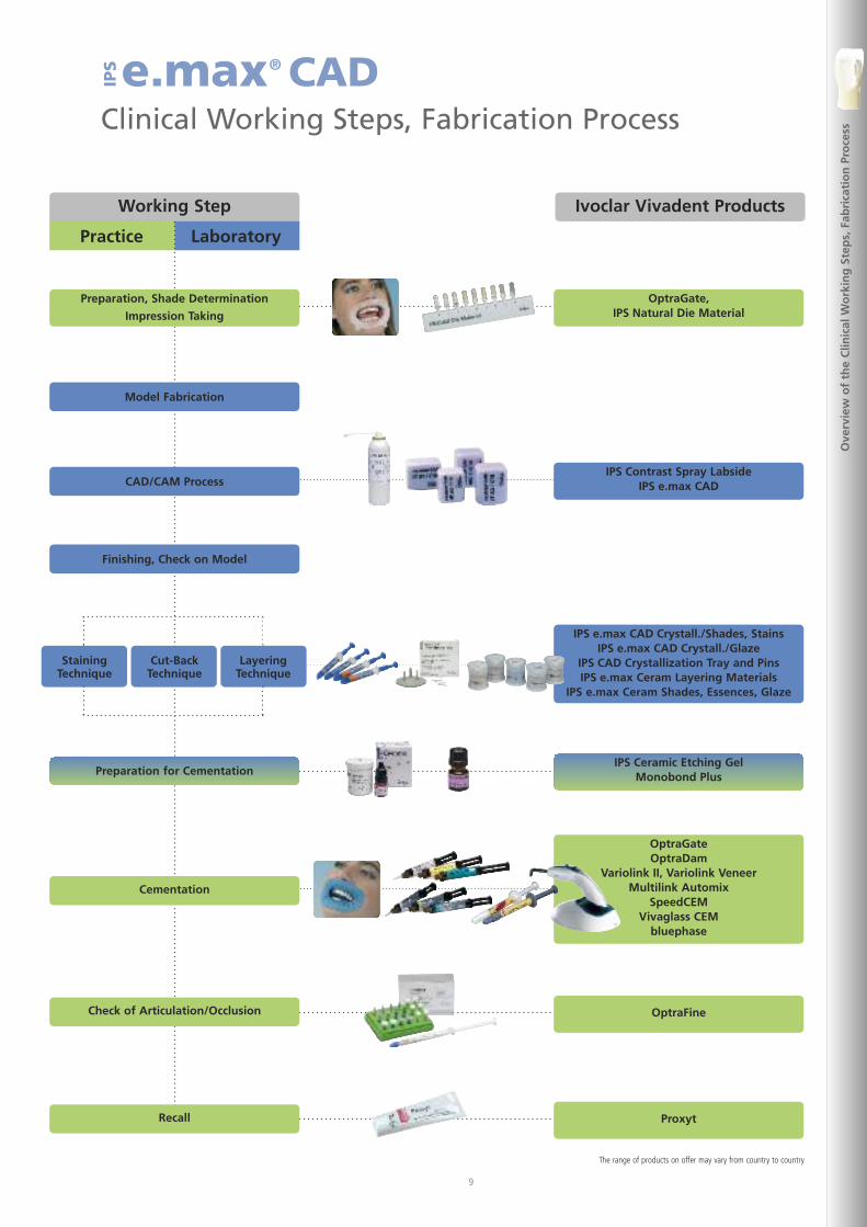
e.max® CADClinical Working Steps, Fabrication Process
IPS
Ove
rvie
wo
fth
eC
linic
alW
ork
ing
Step
s,Fa
bri
cati
on
Pro
cess
Practice
Working Step Ivoclar Vivadent Products
Laboratory
Preparation, Shade Determination
Impression Taking
OptraGate,IPS Natural Die Material
OptraFine
Proxyt
Model Fabrication
CAD/CAM Process
Finishing, Check on Model
Cementation
Check of Articulation/Occlusion
Recall
Preparation for Cementation
StainingTechnique
Cut-BackTechnique
LayeringTechnique
IPS Contrast Spray LabsideIPS e.max CAD
IPS Ceramic Etching GelMonobond Plus
IPS e.max CAD Crystall./Shades, StainsIPS e.max CAD Crystall./Glaze
IPS CAD Crystallization Tray and PinsIPS e.max Ceram Layering Materials
IPS e.max Ceram Shades, Essences, Glaze
The range of products on offer may vary from country to country
OptraGateOptraDam
Variolink II, Variolink VeneerMultilink Automix
SpeedCEMVivaglass CEM
bluephase
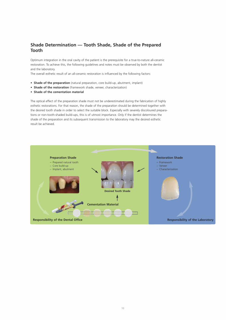
Shade Determination — Tooth Shade, Shade of the PreparedTooth
Optimum integration in the oral cavity of the patient is the prerequisite for a true-to-nature all-ceramic
restoration. To achieve this, the following guidelines and notes must be observed by both the dentist
and the laboratory.
The overall esthetic result of an all-ceramic restoration is influenced by the following factors:
• Shade of the preparation (natural preparation, core build-up, abutment, implant)
• Shade of the restoration (framework shade, veneer, characterization)
• Shade of the cementation material
The optical effect of the preparation shade must not be underestimated during the fabrication of highly
esthetic restorations. For that reason, the shade of the preparation should be determined together with
the desired tooth shade in order to select the suitable block. Especially with severely discoloured prepara-
tions or non-tooth-shaded build-ups, this is of utmost importance. Only if the dentist determines the
shade of the preparation and its subsequent transmission to the laboratory may the desired esthetic
result be achieved.
10
Preparation Shade
– Prepared natural tooth– Core build-up– Implant, abutment
Cementation Material
Desired Tooth Shade
Responsibility of the Dental Office Responsibility of the Laboratory
Restoration Shade
– Framework– Veneer– Characterization
11
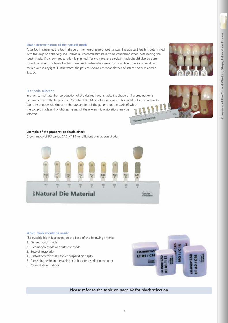
Shade determination of the natural tooth
After tooth cleaning, the tooth shade of the non-prepared tooth and/or the adjacent teeth is determined
with the help of a shade guide. Individual characteristics have to be considered when determining the
tooth shade. If a crown preparation is planned, for example, the cervical shade should also be deter-
mined. In order to achieve the best possible true-to-nature results, shade determination should be
carried out in daylight. Furthermore, the patient should not wear clothes of intense colours and/or
lipstick.
Die shade selection
In order to facilitate the reproduction of the desired tooth shade, the shade of the preparation is
determined with the help of the IPS Natural Die Material shade guide. This enables the technician to
fabricate a model die similar to the preparation of the patient, on the basis of which
the correct shade and brightness values of the all-ceramic restorations may be
selected.
Example of the preparation shade effect
Crown made of IPS e.max CAD HT B1 on different preparation shades.
Which block should be used?
The suitable block is selected on the basis of the following criteria:
1. Desired tooth shade
2. Preparation shade or abutment shade
3. Type of restoration
4. Restoration thickness and/or preparation depth
5. Processing technique (staining, cut-back or layering technique)
6. Cementation material
Please refer to the table on page 62 for block selection
Ove
rvie
wo
fth
eC
linic
alW
ork
ing
Step
s,Fa
bri
cati
on
Pro
cess
12
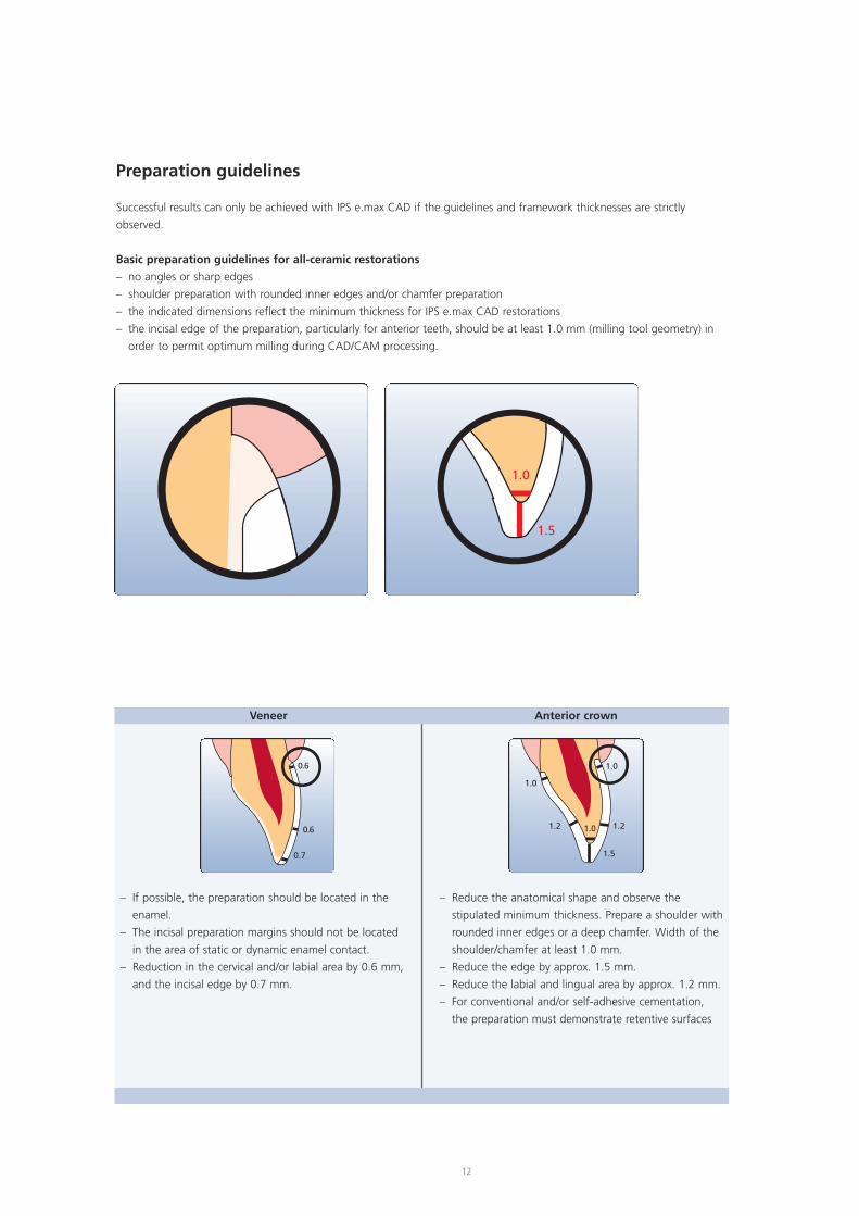
Preparation guidelines
Successful results can only be achieved with IPS e.max CAD if the guidelines and framework thicknesses are strictly
observed.
Basic preparation guidelines for all-ceramic restorations
– no angles or sharp edges
– shoulder preparation with rounded inner edges and/or chamfer preparation
– the indicated dimensions reflect the minimum thickness for IPS e.max CAD restorations
– the incisal edge of the preparation, particularly for anterior teeth, should be at least 1.0 mm (milling tool geometry) in
order to permit optimum milling during CAD/CAM processing.
1.0
1.5
0.6
0.6
0.7
1.0
1.0
1.5
1.2 1.21.0
– If possible, the preparation should be located in the
enamel.
– The incisal preparation margins should not be located
in the area of static or dynamic enamel contact.
– Reduction in the cervical and/or labial area by 0.6 mm,
and the incisal edge by 0.7 mm.
– Reduce the anatomical shape and observe the
stipulated minimum thickness. Prepare a shoulder with
rounded inner edges or a deep chamfer. Width of the
shoulder/chamfer at least 1.0 mm.
– Reduce the edge by approx. 1.5 mm.
– Reduce the labial and lingual area by approx. 1.2 mm.
– For conventional and/or self-adhesive cementation,
the preparation must demonstrate retentive surfaces
Veneer Anterior crown
13
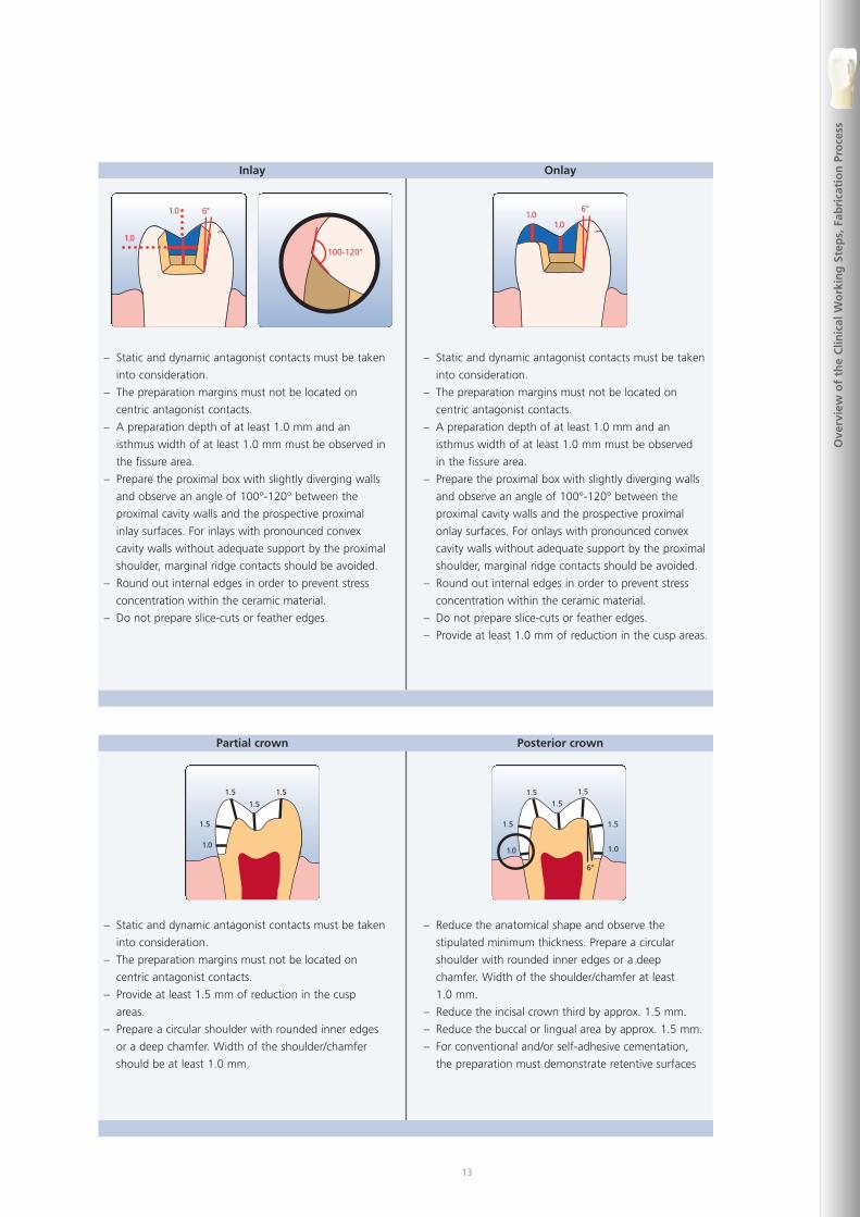
1.5
1.0
1.5
1.5
1.5
1.51.5
1.0 1.0
1.5
1.5
1.5
6°
– Static and dynamic antagonist contacts must be taken
into consideration.
– The preparation margins must not be located on
centric antagonist contacts.
– Provide at least 1.5 mm of reduction in the cusp
areas.
– Prepare a circular shoulder with rounded inner edges
or a deep chamfer. Width of the shoulder/chamfer
should be at least 1.0 mm.
– Reduce the anatomical shape and observe the
stipulated minimum thickness. Prepare a circular
shoulder with rounded inner edges or a deep
chamfer. Width of the shoulder/chamfer at least
1.0 mm.
– Reduce the incisal crown third by approx. 1.5 mm.
– Reduce the buccal or lingual area by approx. 1.5 mm.
– For conventional and/or self-adhesive cementation,
the preparation must demonstrate retentive surfaces
Partial crown Posterior crown
1.0
1.0
6°
100-120°
6°
1.01.0
– Static and dynamic antagonist contacts must be taken
into consideration.
– The preparation margins must not be located on
centric antagonist contacts.
– A preparation depth of at least 1.0 mm and an
isthmus width of at least 1.0 mm must be observed in
the fissure area.
– Prepare the proximal box with slightly diverging walls
and observe an angle of 100°-120° between the
proximal cavity walls and the prospective proximal
inlay surfaces. For inlays with pronounced convex
cavity walls without adequate support by the proximal
shoulder, marginal ridge contacts should be avoided.
– Round out internal edges in order to prevent stress
concentration within the ceramic material.
– Do not prepare slice-cuts or feather edges.
– Static and dynamic antagonist contacts must be taken
into consideration.
– The preparation margins must not be located on
centric antagonist contacts.
– A preparation depth of at least 1.0 mm and an
isthmus width of at least 1.0 mm must be observed
in the fissure area.
– Prepare the proximal box with slightly diverging walls
and observe an angle of 100°-120° between the
proximal cavity walls and the prospective proximal
onlay surfaces. For onlays with pronounced convex
cavity walls without adequate support by the proximal
shoulder, marginal ridge contacts should be avoided.
– Round out internal edges in order to prevent stress
concentration within the ceramic material.
– Do not prepare slice-cuts or feather edges.
– Provide at least 1.0 mm of reduction in the cusp areas.
Inlay Onlay
Ove
rvie
wo
fth
eC
linic
alW
ork
ing
Step
s,Fa
bri
cati
on
Pro
cess
14
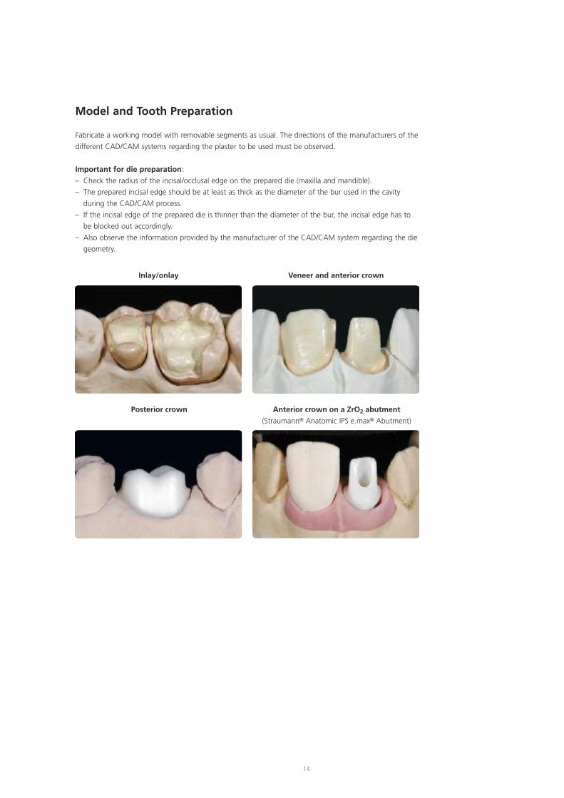
Model and Tooth Preparation
Fabricate a working model with removable segments as usual. The directions of the manufacturers of the
different CAD/CAM systems regarding the plaster to be used must be observed.
Important for die preparation:
– Check the radius of the incisal/occlusal edge on the prepared die (maxilla and mandible).
– The prepared incisal edge should be at least as thick as the diameter of the bur used in the cavity
during the CAD/CAM process.
– If the incisal edge of the prepared die is thinner than the diameter of the bur, the incisal edge has to
be blocked out accordingly.
– Also observe the information provided by the manufacturer of the CAD/CAM system regarding the die
geometry.
Inlay/onlay Veneer and anterior crown
Posterior crown Anterior crown on a ZrO2 abutment
(Straumann® Anatomic IPS e.max® Abutment)
15
Layer thicknesses
The restoration design is key to the success of durable all-ceramic restorations. The more attention is given to the design,
the better the final results and the clinical success will turn out to be. The following basic guidelines have to be observed:
– IPS e.max CAD is the high-strength component of your restoration and must, therefore, always make up at
least 50% of the total layer thickness of the restoration.
– In large preparations and for veneered or partially veneered restorations, the excess available space must be
compensated by the corresponding dimensions of the high-strength IPS e.max CAD component and not by
the IPS e.max Ceram layering material.
– The design of the restoration generated by the software has to be individually adjusted, if necessary, in accordance with
the clinical situation using the design tools.
– The areas that support and reinforce the shape and cusps of the restoration are constructed with the integrated design
tools of the different types of software used.
– In partially veneered restorations, the transition between the layering material and IPS e.max CAD must not be located
in the area of the functional contact points.
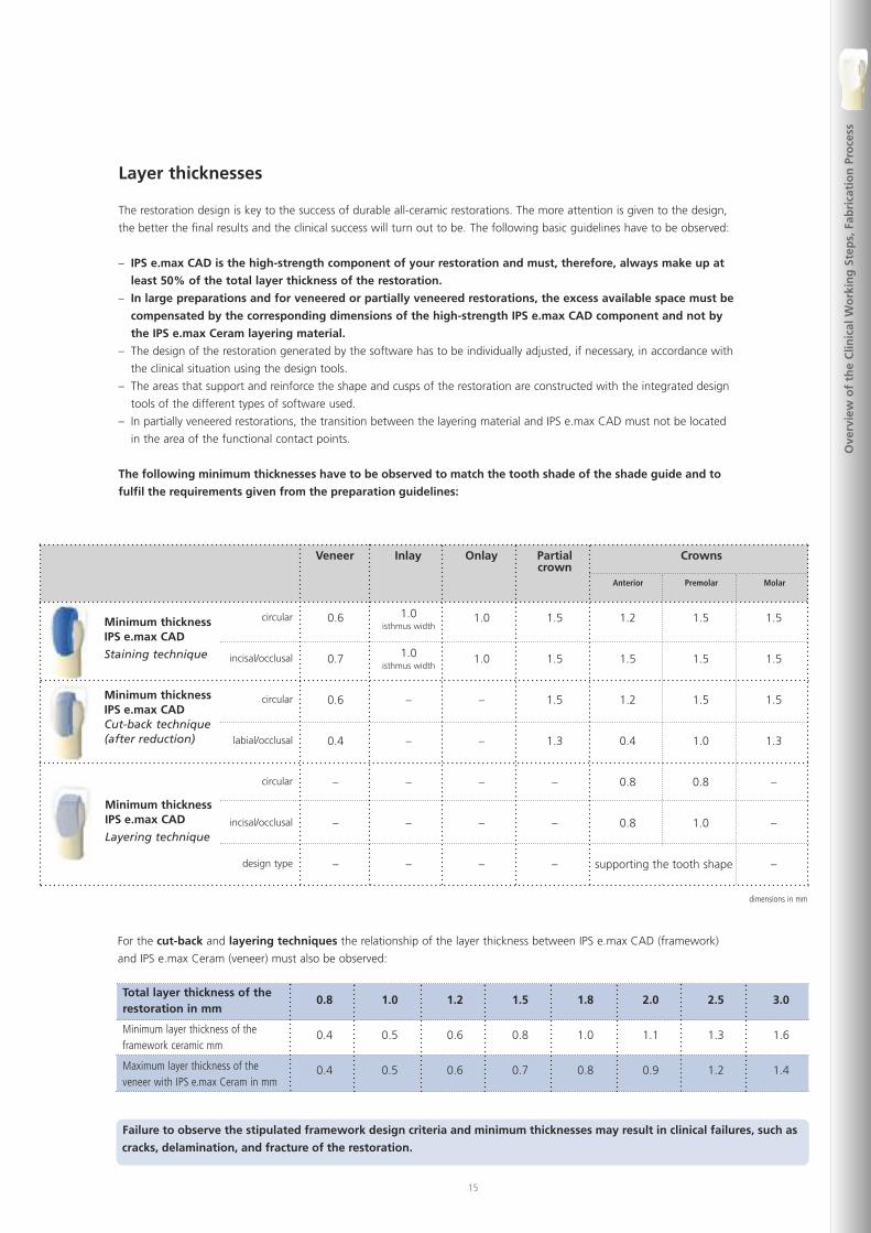
The following minimum thicknesses have to be observed to match the tooth shade of the shade guide and to
fulfil the requirements given from the preparation guidelines:
Veneer Inlay Onlay Partialcrown
Anterior Premolar Molar
circular
incisal/occlusal
circular
labial/occlusal
circular
incisal/occlusal
design type
0.6
0.7
0.6
0.4
–
–
–
1.0isthmus width
1.0isthmus width
–
–
–
–
–
1.0
1.0
–
–
–
–
–
1.5
1.5
1.5
1.3
–
–
–
1.2
1.5
1.2
0.4
0.8
0.8
1.5
1.5
1.5
1.0
0.8
1.0
1.5
1.5
1.5
1.3
–
–
–
Minimum thicknessIPS e.max CAD
Staining technique
Minimum thicknessIPS e.max CADCut-back technique(after reduction)
Minimum thicknessIPS e.max CAD
Layering technique
Crowns
supporting the tooth shape
dimensions in mm
Ove
rvie
wo
fth
eC
linic
alW
ork
ing
Step
s,Fa
bri
cati
on
Pro
cess
Failure to observe the stipulated framework design criteria and minimum thicknesses may result in clinical failures, such as
cracks, delamination, and fracture of the restoration.
Total layer thickness of therestoration in mm
Minimum layer thickness of theframework ceramic mm
Maximum layer thickness of theveneer with IPS e.max Ceram in mm
For the cut-back and layering techniques the relationship of the layer thickness between IPS e.max CAD (framework)
and IPS e.max Ceram (veneer) must also be observed:
0.8
0.4
0.4
1.0
0.5
0.5
1.2
0.6
0.6
1.5
0.8
0.7
1.8
1.0
0.8
2.0
1.1
0.9
2.5
1.3
1.2
3.0
1.6
1.4
16
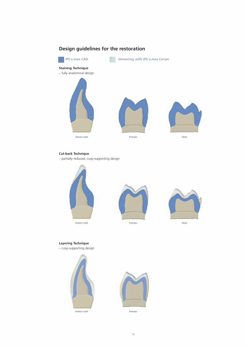
Design guidelines for the restoration
IPS e.max CAD Veneering with IPS e.max Ceram
Staining Technique
– fully anatomical design
Cut-back Technique
– partially reduced, cusp-supporting design
Layering Technique
– cusp-supporting design
Anterior tooth Premolar
Anterior tooth Premolar
Anterior tooth Premolar
Molar
Molar
17
Ove
rvie
wo
fth
eC
linic
alW
ork
ing
Step
s,Fa
bri
cati
on
Pro
cess
CAD/CAM processing
As densification of about 0.2% takes place in IPS e.max CAD during the crystallization process. This factor has been taken
into account in the software. Consequently, the milled IPS e.max CAD restorations demonstrate precision of fit after
crystallization. The fabrication steps are described in the directions for use and user manuals of the different CAD/CAM
systems. The instructions of the manufacturers must be followed:
Information is available from:
Sirona Dental Systems GmbH
Fabrikstrasse 31
64625 Bensheim
Germany
E-mail: [email protected]
www.sirona.com
inLab® is a registered trademark of Sirona DentalSystems GmbH
Information is available from:
KaVo Dental GmbH
Bismarckring 39
88400 Biberach
Germany
E-mail:[email protected]
www.kavo-everest.com
Everest® is a registered trademark ofKaVo Dental GmbH
Information is available from:
Institut Straumann AG
Peter Merian-Weg 12
4052 Basel
Switzerland
E-mail:[email protected]
www.straumann.com
18
In the staining technique, the milled full-contour restorations are completed by applying stains and glaze materials.
Individualized characterizations and glaze can be applied either before or after Crystallization firing. Coordinated materials
are available for the different procedures.
In this way, the use of translucent IPS e.max CAD blocks permit the fabrication of very esthetic restorations on only
slightly or non-discoloured preparations with minimum effort.
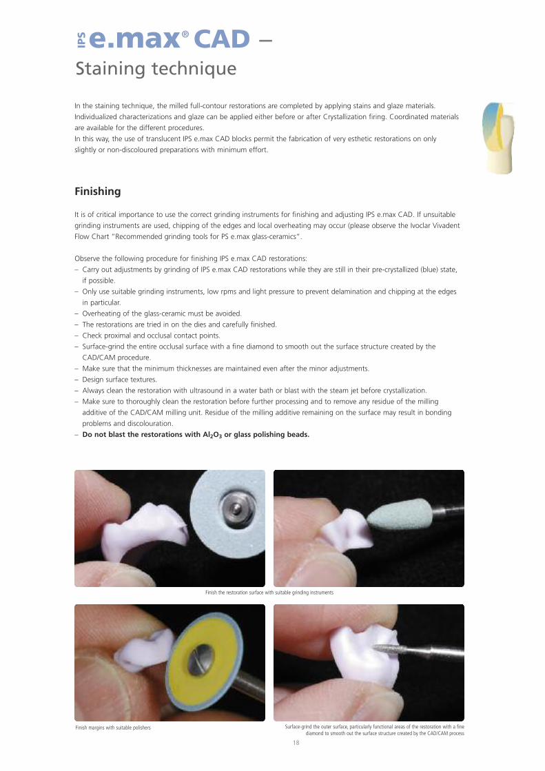
Finishing
It is of critical importance to use the correct grinding instruments for finishing and adjusting IPS e.max CAD. If unsuitable
grinding instruments are used, chipping of the edges and local overheating may occur (please observe the Ivoclar Vivadent
Flow Chart ”Recommended grinding tools for PS e.max glass-ceramics”.
Observe the following procedure for finishing IPS e.max CAD restorations:
– Carry out adjustments by grinding of IPS e.max CAD restorations while they are still in their pre-crystallized (blue) state,
if possible.
– Only use suitable grinding instruments, low rpms and light pressure to prevent delamination and chipping at the edges
in particular.
– Overheating of the glass-ceramic must be avoided.
– The restorations are tried in on the dies and carefully finished.
– Check proximal and occlusal contact points.
– Surface-grind the entire occlusal surface with a fine diamond to smooth out the surface structure created by the
CAD/CAM procedure.
– Make sure that the minimum thicknesses are maintained even after the minor adjustments.
– Design surface textures.
– Always clean the restoration with ultrasound in a water bath or blast with the steam jet before crystallization.
– Make sure to thoroughly clean the restoration before further processing and to remove any residue of the milling
additive of the CAD/CAM milling unit. Residue of the milling additive remaining on the surface may result in bonding
problems and discolouration.
– Do not blast the restorations with Al2O3 or glass polishing beads.
e.max® CAD –Staining technique
IPS
Finish the restoration surface with suitable grinding instruments
Finish margins with suitable polishers Surface-grind the outer surface, particularly functional areas of the restoration with a finediamond to smooth out the surface structure created by the CAD/CAM process
19
Stai
nin
gTe
chn
iqu
e
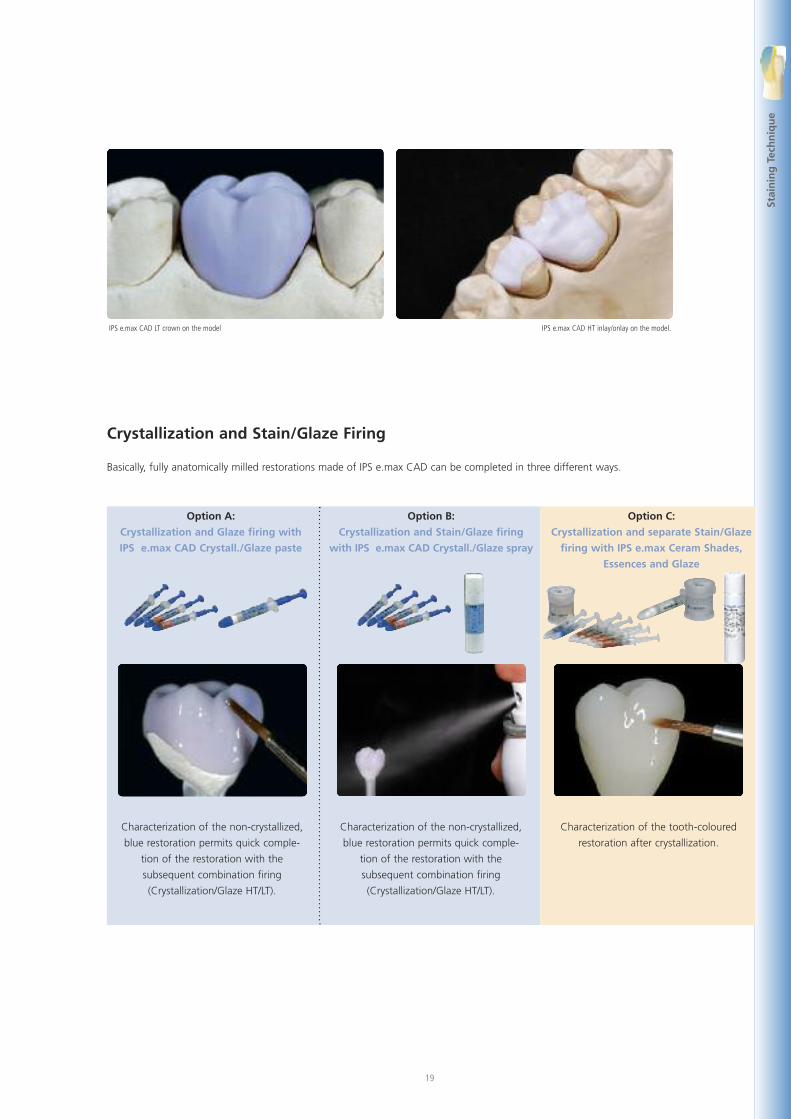
Crystallization and Stain/Glaze Firing
Basically, fully anatomically milled restorations made of IPS e.max CAD can be completed in three different ways.
IPS e.max CAD LT crown on the model IPS e.max CAD HT inlay/onlay on the model.
Option A:
Crystallization and Glaze firing with
IPS e.max CAD Crystall./Glaze paste
Option B:
Crystallization and Stain/Glaze firing
with IPS e.max CAD Crystall./Glaze spray
Option C:
Crystallization and separate Stain/Glaze
firing with IPS e.max Ceram Shades,
Essences and Glaze
Characterization of the non-crystallized,
blue restoration permits quick comple-
tion of the restoration with the
subsequent combination firing
(Crystallization/Glaze HT/LT).
Characterization of the non-crystallized,
blue restoration permits quick comple-
tion of the restoration with the
subsequent combination firing
(Crystallization/Glaze HT/LT).
Characterization of the tooth-coloured
restoration after crystallization.
20
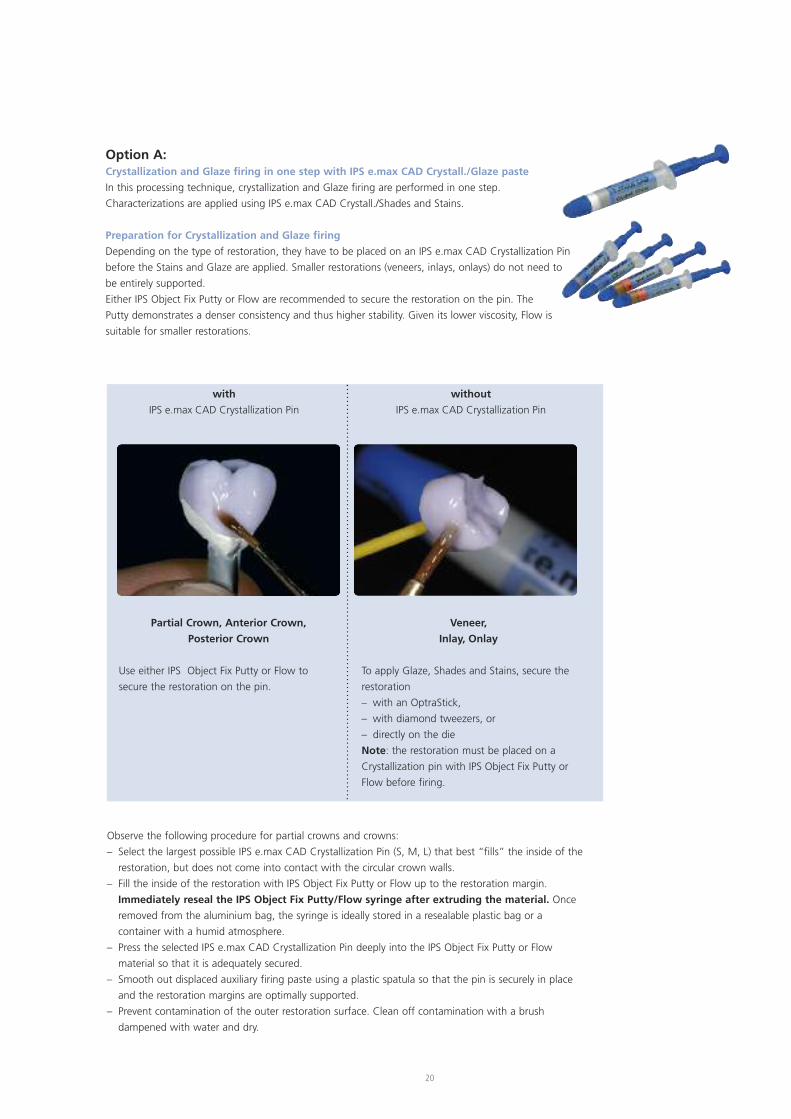
with
IPS e.max CAD Crystallization Pin
without
IPS e.max CAD Crystallization Pin
Partial Crown, Anterior Crown,
Posterior Crown
Use either IPS Object Fix Putty or Flow to
secure the restoration on the pin.
Veneer,
Inlay, Onlay
To apply Glaze, Shades and Stains, secure the
restoration
– with an OptraStick,
– with diamond tweezers, or
– directly on the die
Note: the restoration must be placed on a
Crystallization pin with IPS Object Fix Putty or
Flow before firing.
Option A:Crystallization and Glaze firing in one step with IPS e.max CAD Crystall./Glaze paste
In this processing technique, crystallization and Glaze firing are performed in one step.
Characterizations are applied using IPS e.max CAD Crystall./Shades and Stains.
Preparation for Crystallization and Glaze firing
Depending on the type of restoration, they have to be placed on an IPS e.max CAD Crystallization Pin
before the Stains and Glaze are applied. Smaller restorations (veneers, inlays, onlays) do not need to
be entirely supported.
Either IPS Object Fix Putty or Flow are recommended to secure the restoration on the pin. The
Putty demonstrates a denser consistency and thus higher stability. Given its lower viscosity, Flow is
suitable for smaller restorations.
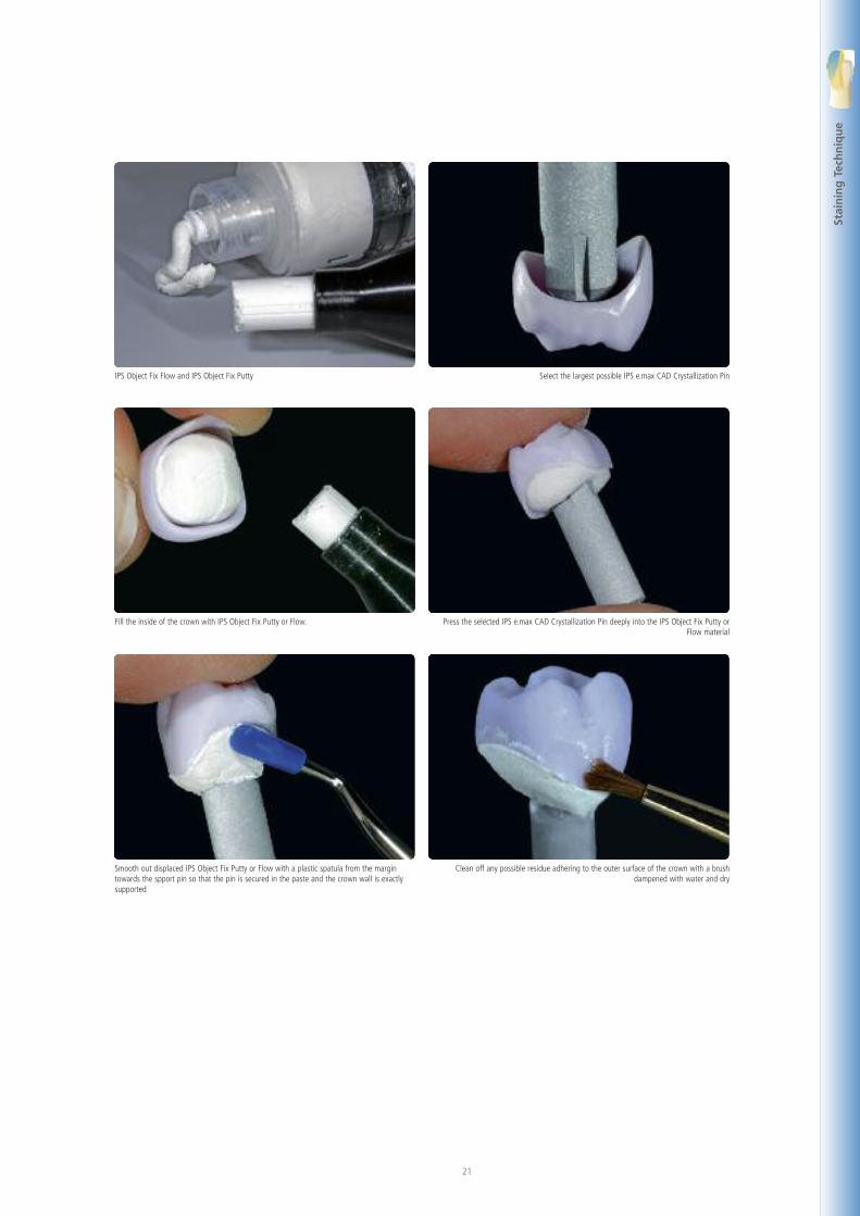
Observe the following procedure for partial crowns and crowns:
– Select the largest possible IPS e.max CAD Crystallization Pin (S, M, L) that best “fills” the inside of the
restoration, but does not come into contact with the circular crown walls.
– Fill the inside of the restoration with IPS Object Fix Putty or Flow up to the restoration margin.
Immediately reseal the IPS Object Fix Putty/Flow syringe after extruding the material. Once
removed from the aluminium bag, the syringe is ideally stored in a resealable plastic bag or a
container with a humid atmosphere.
– Press the selected IPS e.max CAD Crystallization Pin deeply into the IPS Object Fix Putty or Flow
material so that it is adequately secured.
– Smooth out displaced auxiliary firing paste using a plastic spatula so that the pin is securely in place
and the restoration margins are optimally supported.
– Prevent contamination of the outer restoration surface. Clean off contamination with a brush
dampened with water and dry.
21
Stai
nin
gTe
chn
iqu
e
Select the largest possible IPS e.max CAD Crystallization PinIPS Object Fix Flow and IPS Object Fix Putty
Press the selected IPS e.max CAD Crystallization Pin deeply into the IPS Object Fix Putty orFlow material
Fill the inside of the crown with IPS Object Fix Putty or Flow.
Clean off any possible residue adhering to the outer surface of the crown with a brushdampened with water and dry
Smooth out displaced IPS Object Fix Putty or Flow with a plastic spatula from the margintowards the spport pin so that the pin is secured in the paste and the crown wall is exactlysupported
22
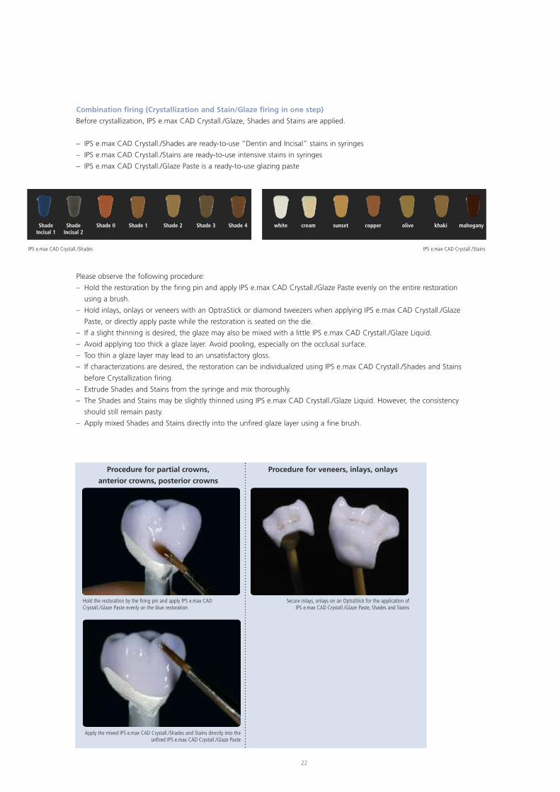
Combination firing (Crystallization and Stain/Glaze firing in one step)
Before crystallization, IPS e.max CAD Crystall./Glaze, Shades and Stains are applied.
– IPS e.max CAD Crystall./Shades are ready-to-use “Dentin and Incisal” stains in syringes
– IPS e.max CAD Crystall./Stains are ready-to-use intensive stains in syringes
– IPS e.max CAD Crystall./Glaze Paste is a ready-to-use glazing paste
ShadeIncisal 1
ShadeIncisal 2
Shade 0 Shade 1 Shade 2 Shade 3 Shade 4 white cream sunset copper olive khaki mahogany
IPS e.max CAD Crystall./Shades IPS e.max CAD Crystall./Stains
Please observe the following procedure:
– Hold the restoration by the firing pin and apply IPS e.max CAD Crystall./Glaze Paste evenly on the entire restoration
using a brush.
– Hold inlays, onlays or veneers with an OptraStick or diamond tweezers when applying IPS e.max CAD Crystall./Glaze
Paste, or directly apply paste while the restoration is seated on the die.
– If a slight thinning is desired, the glaze may also be mixed with a little IPS e.max CAD Crystall./Glaze Liquid.
– Avoid applying too thick a glaze layer. Avoid pooling, especially on the occlusal surface.
– Too thin a glaze layer may lead to an unsatisfactory gloss.
– If characterizations are desired, the restoration can be individualized using IPS e.max CAD Crystall./Shades and Stains
before Crystallization firing.
– Extrude Shades and Stains from the syringe and mix thoroughly.
– The Shades and Stains may be slightly thinned using IPS e.max CAD Crystall./Glaze Liquid. However, the consistency
should still remain pasty.
– Apply mixed Shades and Stains directly into the unfired glaze layer using a fine brush.
Procedure for partial crowns,
anterior crowns, posterior crowns
Procedure for veneers, inlays, onlays
Hold the restoration by the firing pin and apply IPS e.max CADCrystall./Glaze Paste evenly on the blue restoration
Secure inlays, onlays on an OptraStick for the application ofIPS e.max CAD Crystall./Glaze Paste, Shades and Stains
Apply the mixed IPS e.max CAD Crystall./Shades and Stains directly into theunfired IPS e.max CAD Crystall./Glaze Paste
23
23
Stai
nin
gTe
chn
iqu
e
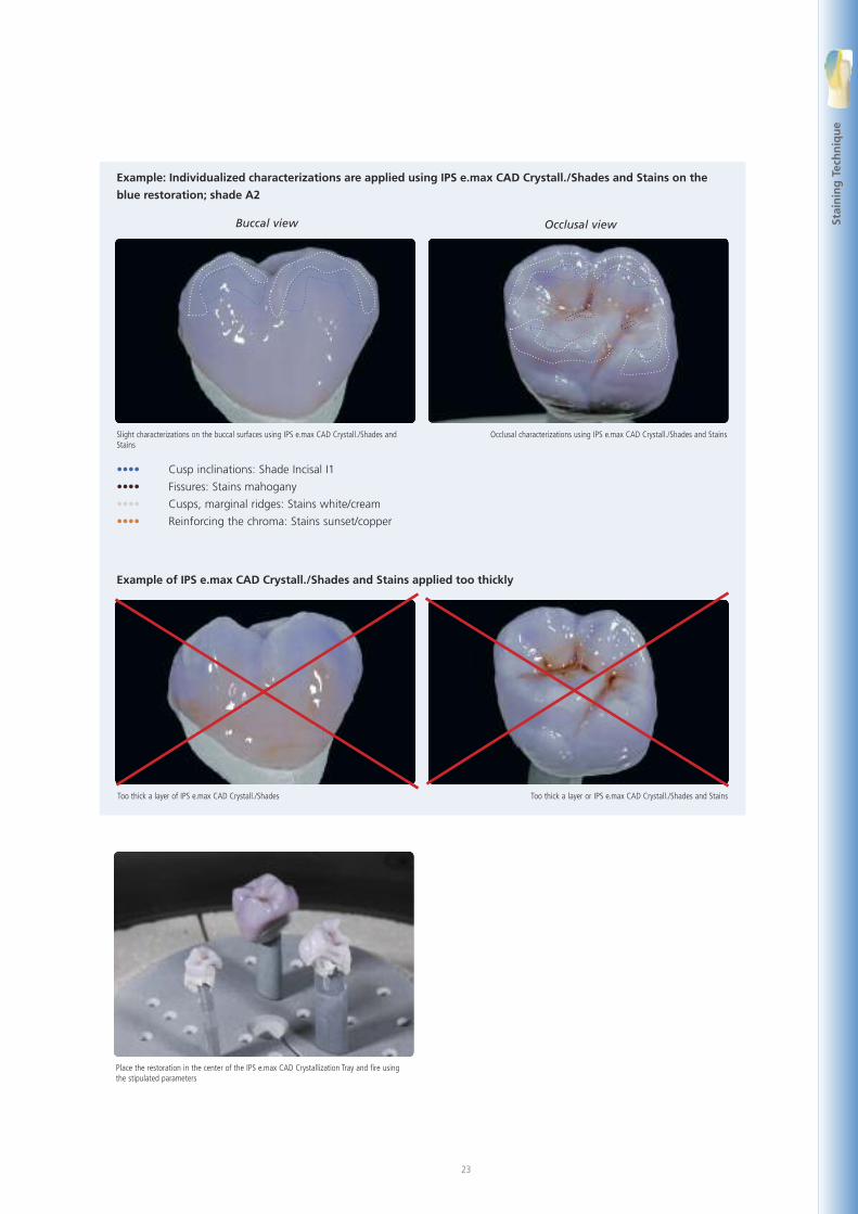
Example: Individualized characterizations are applied using IPS e.max CAD Crystall./Shades and Stains on the
blue restoration; shade A2
Example of IPS e.max CAD Crystall./Shades and Stains applied too thickly
Slight characterizations on the buccal surfaces using IPS e.max CAD Crystall./Shades andStains
Occlusal characterizations using IPS e.max CAD Crystall./Shades and Stains
Occlusal viewBuccal view
Too thick a layer of IPS e.max CAD Crystall./Shades Too thick a layer or IPS e.max CAD Crystall./Shades and Stains
•••• Cusp inclinations: Shade Incisal I1
•••• Fissures: Stains mahogany
•••• Cusps, marginal ridges: Stains white/cream
•••• Reinforcing the chroma: Stains sunset/copper
Place the restoration in the center of the IPS e.max CAD Crystallization Tray and fire usingthe stipulated parameters
24
After glazing and staining, the Combination firing (crystallization/glaze) is conducted in a compatible ceramic furnace
(e.g. Programat® P700). When placing the objects into the furnace and setting the firing parameters, observe the following
points:
– Place the restoration including the pin into the center of the IPS e.max CAD Crystallization Tray.
– Place veneers, inlays and onlays directly on the IPS e.max CAD Crystallization Pin with a small amount of IPS Object Fix
Flow.
– A maximum of 6 restorations can be positioned on the firing tray and crystallized using the Combination firing with
IPS e.max CAD Crystall./Glaze Paste.
– Conduct the Combination firing (Speed Crystallization/Glaze LT/HT) using the stipulated parameters.
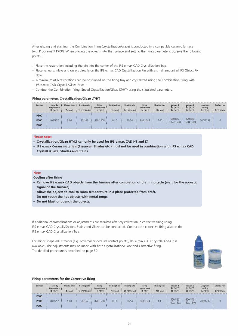
If additional characterizations or adjustments are required after crystallization, a corrective firing using
IPS e.max CAD Crystall./Shades, Stains and Glaze can be conducted. Conduct the corrective firing also on the
IPS e.max CAD Crystallization Tray.
For minor shape adjustments (e.g. proximal or occlusal contact points), IPS e.max CAD Crystall./Add-On is
available . The adjustments may be made with both Crystallization/Glaze and Corrective firing.
The detailed procedure is described on page 30.
Furnace
P300
P500
P700
Stand-bytemperatureB [°C/°F]
403/757
Closing time
S [min]
6:00
Heating rate
t1 [°C/°F/min]
90/162
FiringtemperatureT1 [°C/°F]
820/1508
Holding time
H1 [min]
0:10
Heating rate
t2 [°C/°F/min]
30/54
FiringtemperatureT2 [°C/°F]
840/1544
Holding time
H2 [min]
7:00
Vacuum 111 [°C/°F]12 [°C/°F]
550/8201022/1508
Vacuum 221 [°C/°F]22 [°C/°F]
820/8401508/1540
Long-termcoolingL [°C/°F]
700/1292
Cooling rate
t [°C/°F/min]
0
Furnace
P300
P500
P700
Stand-bytemperatureB [°C/°F]
403/757
Closing time
S [min]
6:00
Heating rate
t1 [°C/°F/min]
90/162
FiringtemperatureT1 [°C/°F]
820/1508
Holding time
H1 [min]
0:10
Heating rate
t2 [°C/°F/min]
30/54
FiringtemperatureT2 [°C/°F]
840/1544
Holding time
H2 [min]
3:00
Vacuum 111 [°C/°F]12 [°C/°F]
550/8201022/1508
Vacuum 221 [°C/°F]22 [°C/°F]
820/8401508/1540
Long-termcoolingL [°C/°F]
700/1292
Cooling rate
t [°C/°F/min]
0
Firing parameters Crystallization/Glaze LT/HT
Please note:
– Crystallization/Glaze HT/LT can only be used for IPS e.max CAD HT and LT.
– IPS e.max Ceram materials (Essences, Shades etc.) must not be used in combination with IPS e.max CAD
Crystall./Glaze, Shades and Stains.
Firing parameters for the Corrective firing
Note
Cooling after firing
– Remove IPS e.max CAD objects from the furnace after completion of the firing cycle (wait for the acoustic
signal of the furnace).
– Allow the objects to cool to room temperature in a place protected from draft.
– Do not touch the hot objects with metal tongs.
– Do not blast or quench the objects.
25
Stai
nin
gTe
chn
iqu
e
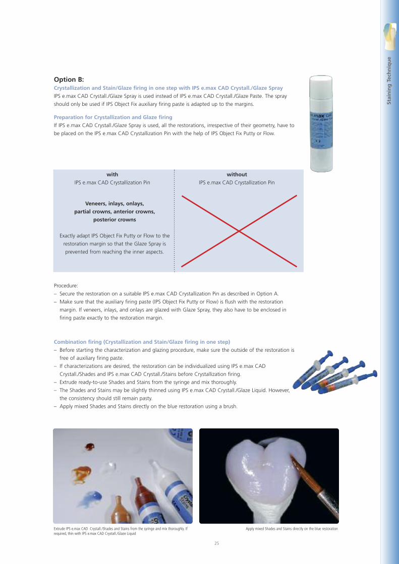
Extrude IPS e.max CAD Crystall./Shades and Stains from the syringe and mix thoroughly. Ifrequired, thin with IPS e.max CAD Crystall./Glaze Liquid
Apply mixed Shades and Stains directly on the blue restoration
Option B:Crystallization and Stain/Glaze firing in one step with IPS e.max CAD Crystall./Glaze Spray
IPS e.max CAD Crystall./Glaze Spray is used instead of IPS e.max CAD Crystall./Glaze Paste. The spray
should only be used if IPS Object Fix auxiliary firing paste is adapted up to the margins.
Preparation for Crystallization and Glaze firing
If IPS e.max CAD Crystall./Glaze Spray is used, all the restorations, irrespective of their geometry, have to
be placed on the IPS e.max CAD Crystallization Pin with the help of IPS Object Fix Putty or Flow.
with
IPS e.max CAD Crystallization Pin
without
IPS e.max CAD Crystallization Pin
Veneers, inlays, onlays,
partial crowns, anterior crowns,
posterior crowns
Exactly adapt IPS Object Fix Putty or Flow to the
restoration margin so that the Glaze Spray is
prevented from reaching the inner aspects.
Procedure:
– Secure the restoration on a suitable IPS e.max CAD Crystallization Pin as described in Option A.
– Make sure that the auxiliary firing paste (IPS Object Fix Putty or Flow) is flush with the restoration
margin. If veneers, inlays, and onlays are glazed with Glaze Spray, they also have to be enclosed in
firing paste exactly to the restoration margin.
Combination firing (Crystallization and Stain/Glaze firing in one step)
– Before starting the characterization and glazing procedure, make sure the outside of the restoration is
free of auxiliary firing paste.
– If characterizations are desired, the restoration can be individualized using IPS e.max CAD
Crystall./Shades and IPS e.max CAD Crystall./Stains before Crystallization firing.
– Extrude ready-to-use Shades and Stains from the syringe and mix thoroughly.
– The Shades and Stains may be slightly thinned using IPS e.max CAD Crystall./Glaze Liquid. However,
the consistency should still remain pasty.
– Apply mixed Shades and Stains directly on the blue restoration using a brush.
26
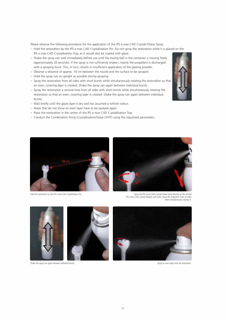
Hold the restoration by the IPS e.max CAD Crystallization Pin. Spray the IPS e.max CAD Crystall./Glaze Spray directly on the unfiredIPS e.max CAD Crystall./Shades and Stains. Spray the restoration from all sides
while simultaneously rotating it.
Shake the spray can again between individual bursts. Spray an even layer onto the restoration.
Please observe the following procedure for the application of the IPS e.max CAD Crystall./Glaze Spray:
– Hold the restoration by the IPS e.max CAD Crystallization Pin. Do not spray the restoration while it is placed on the
IPS e.max CAD Crystallization Tray, as it would also be coated with glaze.
– Shake the spray can well immediately before use until the mixing ball in the container is moving freely
(approximately 20 seconds). If the spray is not sufficiently shaken, mainly the propellant is discharged
with a spraying burst. This, in turn, results in insufficient application of the glazing powder.
– Observe a distance of approx. 10 cm between the nozzle and the surface to be sprayed.
– Hold the spray can as upright as possible during spraying.
– Spray the restoration from all sides with short bursts while simultaneously rotating the restoration so that
an even, covering layer is created. Shake the spray can again between individual bursts.
– Spray the restoration a second time from all sides with short bursts while simultaneously rotating the
restoration so that an even, covering layer is created. Shake the spray can again between individual
bursts.
– Wait briefly until the glaze layer is dry and has assumed a whitish colour.
– Areas that do not show an even layer have to be sprayed again.
– Place the restoration in the center of the IPS e.max CAD Crystallization Tray.
– Conduct the Combination firing (Crystallization/Glaze LT/HT) using the stipulated parameters.
27
Stai
nin
gTe
chn
iqu
e
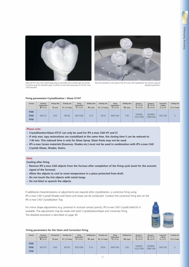
Allow the IPS e.max CAD Crystall./Glaze Spray to dry briefly until a whitish layer has formed.If required, spray the restoration again to achieve an even Glaze Spray layer on the IPS e.maxCAD restoration.
Place the restoration in the center of the IPS e.max CAD Crystallization Tray and fire using thestipulated parameters.
Firing parameters for the Stain and Correction firing
Firing parameters Crystallization / Glaze LT/HT
Please note:
– Crystallization/Glaze HT/LT can only be used for IPS e.max CAD HT and LT.
– If only max. two restorations are crystallized at the same time, the closing time S can be reduced to
1:30 min. This reduced time is only for Glaze Spray. Glaze Paste may not be used.
– IPS e.max Ceram materials (Essences, Shades etc.) must not be used in combination with IPS e.max CAD
Crystall./Glaze, Shades, Stains.
Furnace
P300
P500
P700
Stand-bytemperatureB [°C/°F]
403/757
Closing time
S [min]
6:00
Heating rate
t1 [°C/°F/min]
90/162
FiringtemperatureT1 [°C/°F]
820/1508
Holding time
H1 [min]
0:10
Heating rate
t2 [°C/°F/min]
30/54
FiringtemperatureT2 [°C/°F]
840/1544
Holding time
H2 [min]
7:00
Vacuum 111 [°C/°F]12 [°C/°F]
550/8201022/1508
Vacuum 221 [°C/°F]22 [°C/°F]
820/8401508/1540
Long-termcoolingL [°C/°F]
700/1292
Cooling rate
t [°C/°F/min]
0
Furnace
P300
P500
P700
Stand-bytemperatureB [°C/°F]
403/757
Closing time
S [min]
6:00
Heating rate
t1 [°C/°F/min]
90/162
FiringtemperatureT1 [°C/°F]
820/1508
Holding time
H1 [min]
0:10
Heating rate
t2 [°C/°F/min]
30/54
FiringtemperatureT2 [°C/°F]
840/1544
Holding time
H2 [min]
3:00
Vacuum 111 [°C/°F]12 [°C/°F]
550/8201022/1508
Vacuum 221 [°C/°F]22 [°C/°F]
820/8401508/1540
Long-termcoolingL [°C/°F]
700/1292
Cooling rate
t [°C/°F/min]
0
If additional characterizations or adjustments are required after crystallization, a corrective firing using
IPS e.max CAD Crystall./Shades and Stains and Glaze can be conducted. Conduct the corrective firing also on the
IPS e.max CAD Crystallization Tray.
For minor shape adjustments (e.g. proximal or occlusal contact points), IPS e.max CAD Crystall./Add-On is
available. The adjustments may be made with both Crystallization/Glaze and Corrective firing.
The detailed procedure is described on page 30.
Note
Cooling after firing
– Remove IPS e.max CAD objects from the furnace after completion of the firing cycle (wait for the acoustic
signal of the furnace).
– Allow the objects to cool to room temperature in a place protected from draft.
– Do not touch the hot objects with metal tongs.
– Do not blast or quench the objects.
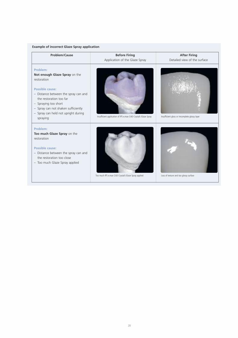
Problem/Cause Before Firing
Application of the Glaze Spray
After Firing
Detailed view of the surface
Insufficient application of IPS e.max CAD Crystall./Glaze Spray
Problem:
Not enough Glaze Spray on the
restoration
Possible cause:
– Distance between the spray can and
the restoration too far
– Spraying too short
– Spray can not shaken sufficiently
– Spray can held not upright during
spraying Insufficient gloss or imcomplete glossy layer
Too much IPS e.max CAD Crystall./Glaze Spray applied
Problem:
Too much Glaze Spray on the
restoration
Possible cause:
– Distance between the spray can and
the restoration too close
– Too much Glaze Spray applied
Loss of texture and too glossy surface
Example of incorrect Glaze Spray application
28
29
Stai
nin
gTe
chn
iqu
e
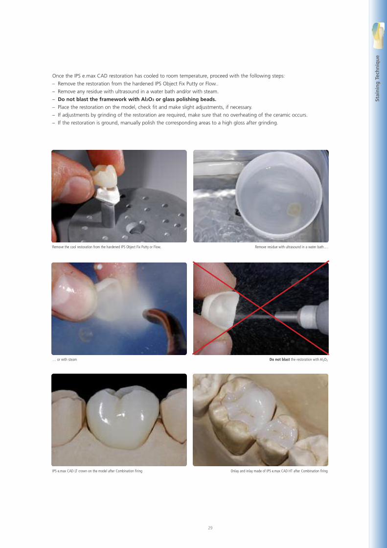
Once the IPS e.max CAD restoration has cooled to room temperature, proceed with the following steps:
– Remove the restoration from the hardened IPS Object Fix Putty or Flow..
– Remove any residue with ultrasound in a water bath and/or with steam.
– Do not blast the framework with Al2O3 or glass polishing beads.
– Place the restoration on the model, check fit and make slight adjustments, if necessary.
– If adjustments by grinding of the restoration are required, make sure that no overheating of the ceramic occurs.
– If the restoration is ground, manually polish the corresponding areas to a high gloss after grinding.
Remove the cool restoration from the hardened IPS Object Fix Putty or Flow. Remove residue with ultrasound in a water bath…
… or with steam Do not blast the restoration with Al2O3
IPS e.max CAD LT crown on the model after Combination firing Onlay and inlay made of IPS e.max CAD HT after Combination firing
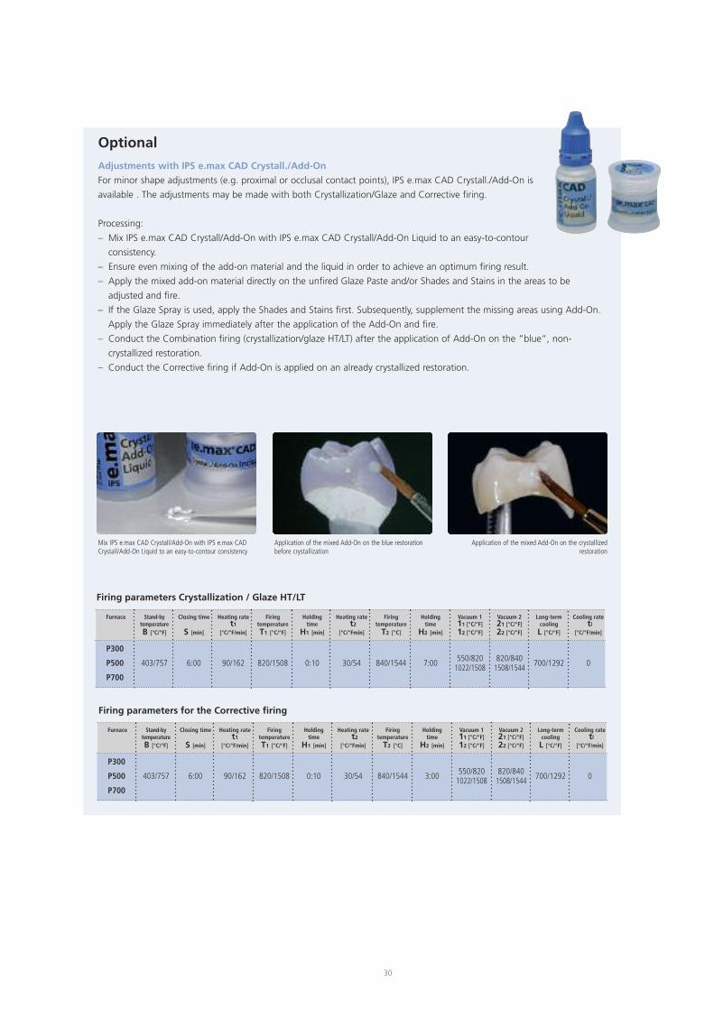
Optional
Adjustments with IPS e.max CAD Crystall./Add-On
For minor shape adjustments (e.g. proximal or occlusal contact points), IPS e.max CAD Crystall./Add-On is
available . The adjustments may be made with both Crystallization/Glaze and Corrective firing.
Processing:
– Mix IPS e.max CAD Crystall/Add-On with IPS e.max CAD Crystall/Add-On Liquid to an easy-to-contour
consistency.
– Ensure even mixing of the add-on material and the liquid in order to achieve an optimum firing result.
– Apply the mixed add-on material directly on the unfired Glaze Paste and/or Shades and Stains in the areas to be
adjusted and fire.
– If the Glaze Spray is used, apply the Shades and Stains first. Subsequently, supplement the missing areas using Add-On.
Apply the Glaze Spray immediately after the application of the Add-On and fire.
– Conduct the Combination firing (crystallization/glaze HT/LT) after the application of Add-On on the ”blue”, non-
crystallized restoration.
– Conduct the Corrective firing if Add-On is applied on an already crystallized restoration.
Mix IPS e.max CAD Crystall/Add-On with IPS e.max CADCrystall/Add-On Liquid to an easy-to-contour consistency
Application of the mixed Add-On on the blue restorationbefore crystallization
Application of the mixed Add-On on the crystallizedrestoration
Firing parameters for the Corrective firing
30
Firing parameters Crystallization / Glaze HT/LT
Furnace
P300
P500
P700
Stand-bytemperatureB [°C/°F]
403/757
Closing time
S [min]
6:00
Heating ratet1
[°C/°F/min]
90/162
FiringtemperatureT1 [°C/°F]
820/1508
Holdingtime
H1 [min]
0:10
Heating ratet2
[°C/°Fmin]
30/54
Firingtemperature
T2 [°C]
840/1544
Holdingtime
H2 [min]
3:00
Vacuum 111 [°C/°F]12 [°C/°F]
550/8201022/1508
Vacuum 221 [°C/°F]22 [°C/°F]
820/8401508/1544
Long-termcoolingL [°C/°F]
700/1292
Cooling ratetl
[°C/°F/min]
0
Furnace
P300
P500
P700
Stand-bytemperatureB [°C/°F]
403/757
Closing time
S [min]
6:00
Heating ratet1
[°C/°F/min]
90/162
FiringtemperatureT1 [°C/°F]
820/1508
Holdingtime
H1 [min]
0:10
Heating ratet2
[°C/°Fmin]
30/54
Firingtemperature
T2 [°C]
840/1544
Holdingtime
H2 [min]
7:00
Vacuum 111 [°C/°F]12 [°C/°F]
550/8201022/1508
Vacuum 221 [°C/°F]22 [°C/°F]
820/8401508/1544
Long-termcoolingL [°C/°F]
700/1292
Cooling ratetl
[°C/°F/min]
0
31
Stai
nin
gTe
chn
iqu
e
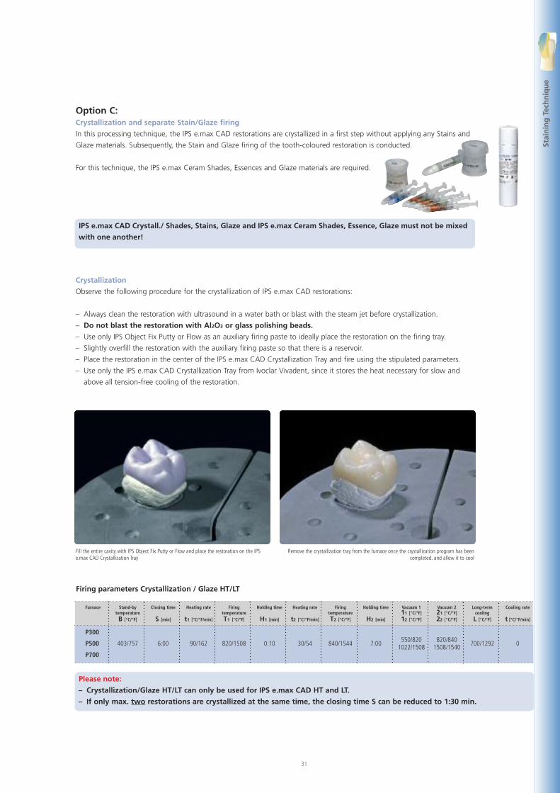
Option C:Crystallization and separate Stain/Glaze firing
In this processing technique, the IPS e.max CAD restorations are crystallized in a first step without applying any Stains and
Glaze materials. Subsequently, the Stain and Glaze firing of the tooth-coloured restoration is conducted.
For this technique, the IPS e.max Ceram Shades, Essences and Glaze materials are required.
IPS e.max CAD Crystall./ Shades, Stains, Glaze and IPS e.max Ceram Shades, Essence, Glaze must not be mixed
with one another!
Crystallization
Observe the following procedure for the crystallization of IPS e.max CAD restorations:
– Always clean the restoration with ultrasound in a water bath or blast with the steam jet before crystallization.
– Do not blast the restoration with Al2O3 or glass polishing beads.
– Use only IPS Object Fix Putty or Flow as an auxiliary firing paste to ideally place the restoration on the firing tray.
– Slightly overfill the restoration with the auxiliary firing paste so that there is a reservoir.
– Place the restoration in the center of the IPS e.max CAD Crystallization Tray and fire using the stipulated parameters.
– Use only the IPS e.max CAD Crystallization Tray from Ivoclar Vivadent, since it stores the heat necessary for slow and
above all tension-free cooling of the restoration.
Fill the entire cavity with IPS Object Fix Putty or Flow and place the restoration on the IPSe.max CAD Crystallization Tray
Remove the crystallization tray from the furnace once the crystallization program has beencompleted. and allow it to cool
Firing parameters Crystallization / Glaze HT/LT
Please note:
– Crystallization/Glaze HT/LT can only be used for IPS e.max CAD HT and LT.
– If only max. two restorations are crystallized at the same time, the closing time S can be reduced to 1:30 min.
Furnace
P300
P500
P700
Stand-bytemperatureB [°C/°F]
403/757
Closing time
S [min]
6:00
Heating rate
t1 [°C/°F/min]
90/162
FiringtemperatureT1 [°C/°F]
820/1508
Holding time
H1 [min]
0:10
Heating rate
t2 [°C/°F/min]
30/54
FiringtemperatureT2 [°C/°F]
840/1544
Holding time
H2 [min]
7:00
Vacuum 111 [°C/°F]12 [°C/°F]
550/8201022/1508
Vacuum 221 [°C/°F]22 [°C/°F]
820/8401508/1540
Long-termcoolingL [°C/°F]
700/1292
Cooling rate
t [°C/°F/min]
0
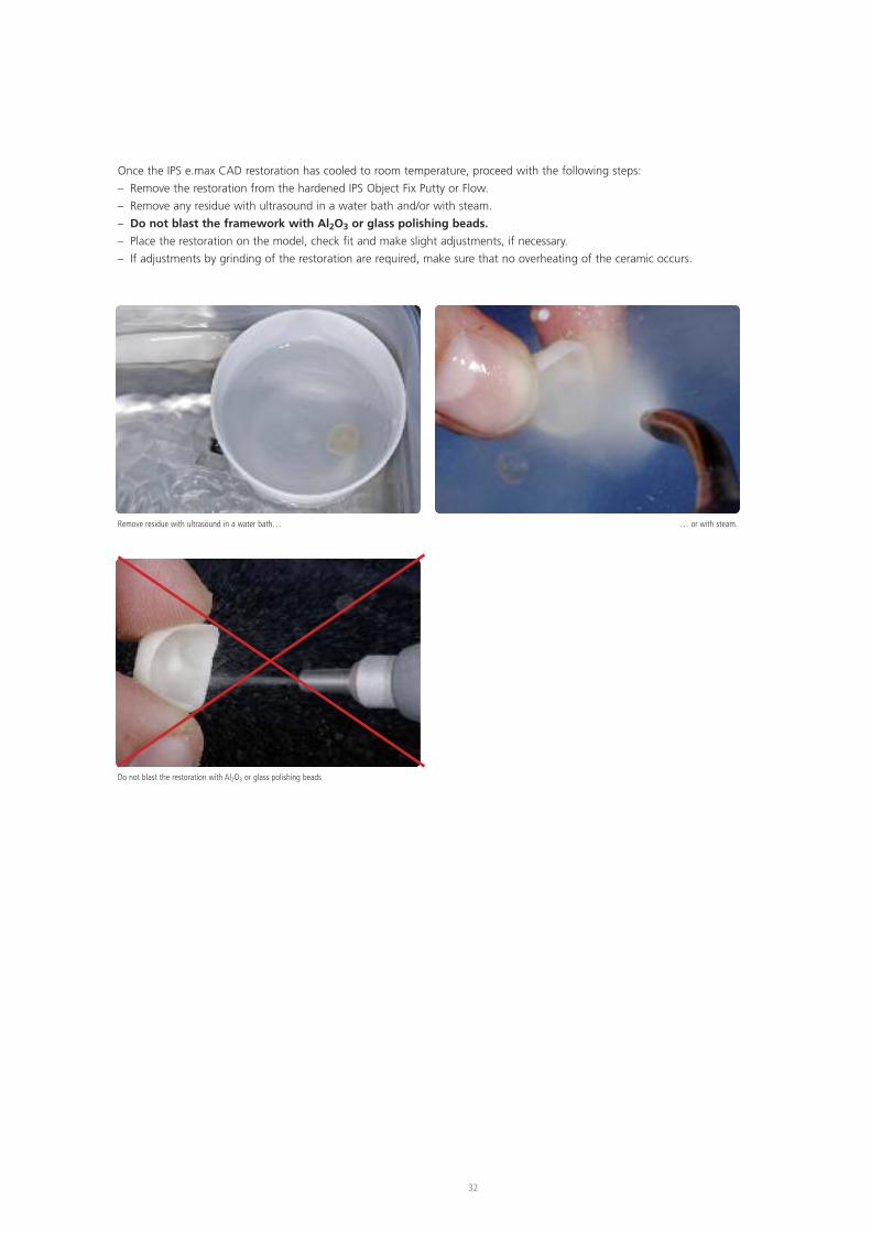
Once the IPS e.max CAD restoration has cooled to room temperature, proceed with the following steps:
– Remove the restoration from the hardened IPS Object Fix Putty or Flow.
– Remove any residue with ultrasound in a water bath and/or with steam.
– Do not blast the framework with Al2O3 or glass polishing beads.
– Place the restoration on the model, check fit and make slight adjustments, if necessary.
– If adjustments by grinding of the restoration are required, make sure that no overheating of the ceramic occurs.
Remove residue with ultrasound in a water bath… … or with steam.
Do not blast the restoration with Al2O3 or glass polishing beads
32
33
Stai
nin
gTe
chn
iqu
e
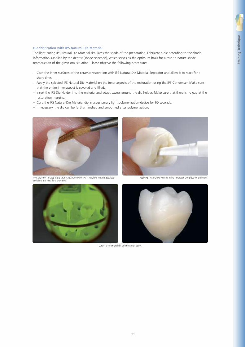
Die fabrication with IPS Natural Die Material
The light-curing IPS Natural Die Material simulates the shade of the preparation. Fabricate a die according to the shade
information supplied by the dentist (shade selection), which serves as the optimum basis for a true-to-nature shade
reproduction of the given oral situation. Please observe the following procedure:
– Coat the inner surfaces of the ceramic restoration with IPS Natural Die Material Separator and allow it to react for a
short time.
– Apply the selected IPS Natural Die Material on the inner aspects of the restoration using the IPS Condenser. Make sure
that the entire inner aspect is covered and filled.
– Insert the IPS Die Holder into the material and adapt excess around the die holder. Make sure that there is no gap at the
restoration margins.
– Cure the IPS Natural Die Material die in a customary light polymerization device for 60 seconds.
– If necessary, the die can be further finished and smoothed after polymerization.
Coat the inner surfaces of the ceramic restoration with IPS Natural Die Material Separatorand allow it to react for a short time.
Apply IPS Natural Die Material in the restoration and place the die holder.
Cure in a customary light polymerization device.
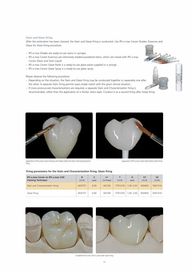
Firing parameters for the Stain and Characterization firing, Glaze firing
IPS e.max Ceram on IPS e.max CAD B S t� T H V1 V2Staining Technique [°C/°F] [min] [°C/°F/min] [°C/°F] [min] [°C/°F] [°C/°F]
Stain and Characterization firing 403/757 6:00 60/108 770/1418 1:00-2:00 450/842 769/1416
Glaze firing 403/757 6:00 60/108 770/1418 1:00-2:00 450/842 769/1416
Completed IPS e.max CAD LT crown after Glaze firing
34
Stain and Glaze firing
After the restoration has been cleaned, the Stain and Glaze firing is conducted. Use IPS e.max Ceram Shades, Essences and
Glaze for these firing procedure.
– IPS e.max Shades are ready-to-use stains in syringes.
– IPS e.max Ceram Essences are intensively shaded powdered stains, which are mixed with IPS e.max
Ceram Glaze and Stain Liquid.
– IPS e.max Ceram Glaze Paste is a ready-to-use glaze paste supplied in a syringe.
– IPS e.max Ceram Glaze Spray is a ready-to-use glaze spray.
Please observe the following procedure:
– Depending on the situation, the Stain and Glaze firing may be conducted together or separately one after
the other. A separate Stain firing permits exact shade match with the given clinical situation.
– If more pronounced characterizations are required, a separate Stain and Characterization firing is
recommended, rather than the application of a thicker stains layer. Conduct it as a second firing after Glaze firing.
Application of IPS e.max Ceram Glaze before Glaze firing.Application of IPS e.max Ceram Essences and Shades before the Stain and Characterizationfiring.
35
Cu
t-b
ack
Tech
niq
ue
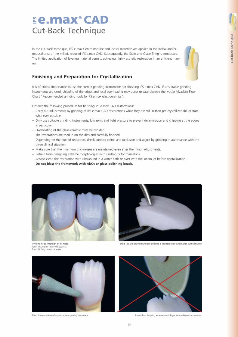
e.max® CADCut-Back Technique
IPS
In the cut-back technique, IPS e.max Ceram Impulse and Incisal materials are applied in the incisal and/or
occlusal area of the milled, reduced IPS e.max CAD. Subsequently, the Stain and Glaze firing is conducted.
The limited application of layering material permits achieving highly esthetic restoration in an efficient man-
ner.
Finishing and Preparation for Crystallization
It is of critical importance to use the correct grinding instruments for finishing IPS e.max CAD. If unsuitable grinding
instruments are used, chipping of the edges and local overheating may occur (please observe the Ivoclar Vivadent Flow
Chart ”Recommended grinding tools for PS e.max glass-ceramics”.
Observe the following procedure for finishing IPS e.max CAD restorations:
– Carry out adjustments by grinding of IPS e.max CAD restorations while they are still in their pre-crystallized (blue) state,
whenever possible.
– Only use suitable grinding instruments, low rpms and light pressure to prevent delamination and chipping at the edges
in particular.
– Overheating of the glass-ceramic must be avoided.
– The restorations are tried in on the dies and carefully finished.
– Depending on the type of reduction, check contact points and occlusion and adjust by grinding in accordance with the
given clinical situation.
– Make sure that the minimum thicknesses are maintained even after the minor adjustments.
– Refrain from designing extreme morphologies with undercuts for mamelons.
– Always clean the restoration with ultrasound in a water bath or blast with the steam jet before crystallization.
– Do not blast the framework with Al2O3 or glass polishing beads.
Try in the milled restoration on the model.Tooth 11: anterior crown with cut-backTooth 21: fully anatomical veneer
Make sure that the minimum layer thickness of the restoration is maintained during finishing
Finish the restoration surface with suitable grinding instruments Refrain from designing extreme morphologies with undercuts for mamelons
36
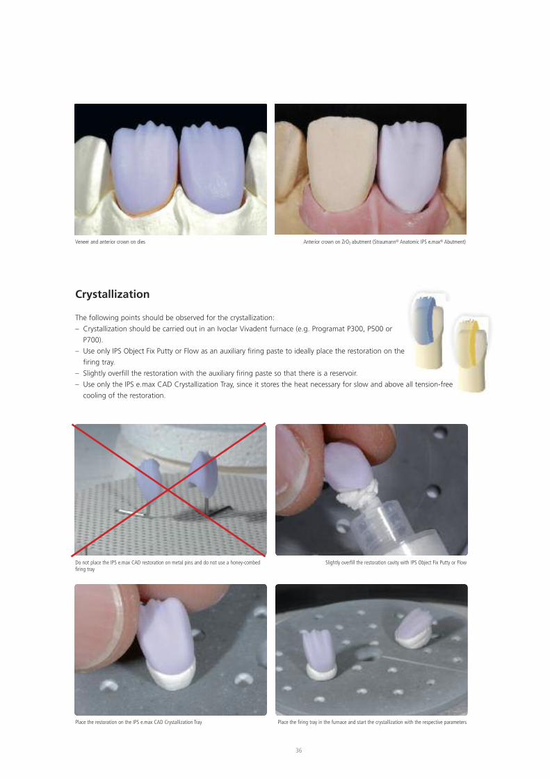
Veneer and anterior crown on dies Anterior crown on ZrO2 abutment (Straumann® Anatomic IPS e.max® Abutment)
Do not place the IPS e.max CAD restoration on metal pins and do not use a honey-combedfiring tray
Slightly overfill the restoration cavity with IPS Object Fix Putty or Flow
Place the restoration on the IPS e.max CAD Crystallization Tray Place the firing tray in the furnace and start the crystallization with the respective parameters
Crystallization
The following points should be observed for the crystallization:
– Crystallization should be carried out in an Ivoclar Vivadent furnace (e.g. Programat P300, P500 or
P700).
– Use only IPS Object Fix Putty or Flow as an auxiliary firing paste to ideally place the restoration on the
firing tray.
– Slightly overfill the restoration with the auxiliary firing paste so that there is a reservoir.
– Use only the IPS e.max CAD Crystallization Tray, since it stores the heat necessary for slow and above all tension-free
cooling of the restoration.
Cu
t-B
ack
Tech
niq
ue
37
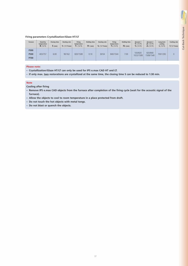
Firing parameters Crystallization/Glaze HT/LT
Please note:
– Crystallization/Glaze HT/LT can only be used for IPS e.max CAD HT and LT.
– If only max. two restorations are crystallized at the same time, the closing time S can be reduced to 1:30 min.
Furnace
P300
P500
P700
Stand-bytemperatureB [°C/°F]
403/757
Closing time
S [min]
6:00
Heating rate
t1 [°C/°F/min]
90/162
FiringtemperatureT1 [°C/°F]
820/1508
Holding time
H1 [min]
0:10
Heating rate
t2 [°C/°F/min]
30/54
FiringtemperatureT2 [°C/°F]
840/1544
Holding time
H2 [min]
7:00
Vacuum 111 [°C/°F]12 [°C/°F]
550/8201022/1508
Vacuum 221 [°C/°F]22 [°C/°F]
820/8401508/1540
Long-termcoolingL [°C/°F]
700/1292
Cooling rate
t [°C/°F/min]
0
Note
Cooling after firing
– Remove IPS e.max CAD objects from the furnace after completion of the firing cycle (wait for the acoustic signal of the
furnace).
– Allow the objects to cool to room temperature in a place protected from draft.
– Do not touch the hot objects with metal tongs.
– Do not blast or quench the objects.
38
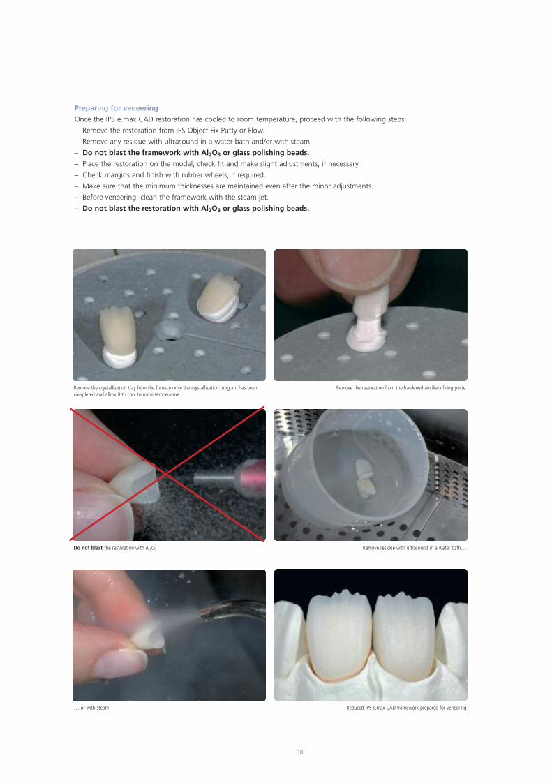
Preparing for veneering
Once the IPS e.max CAD restoration has cooled to room temperature, proceed with the following steps:
– Remove the restoration from IPS Object Fix Putty or Flow.
– Remove any residue with ultrasound in a water bath and/or with steam.
– Do not blast the framework with Al2O3 or glass polishing beads.
– Place the restoration on the model, check fit and make slight adjustments, if necessary.
– Check margins and finish with rubber wheels, if required.
– Make sure that the minimum thicknesses are maintained even after the minor adjustments.
– Before veneering, clean the framework with the steam jet.
– Do not blast the restoration with Al2O3 or glass polishing beads.
Remove the crystallization tray from the furnace once the crystallization program has beencompleted and allow it to cool to room temperature
Remove the restoration from the hardened auxiliary firing paste
Do not blast the restoration with Al2O3 Remove residue with ultrasound in a water bath…
… or with steam Reduced IPS e.max CAD framework prepared for veneering
39
Cu
t-B
ack
Tech
niq
ue
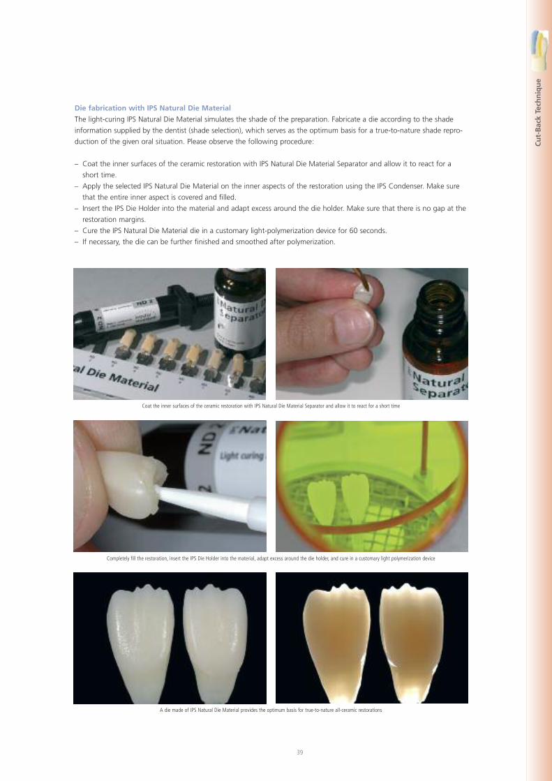
Coat the inner surfaces of the ceramic restoration with IPS Natural Die Material Separator and allow it to react for a short time
Die fabrication with IPS Natural Die Material
The light-curing IPS Natural Die Material simulates the shade of the preparation. Fabricate a die according to the shade
information supplied by the dentist (shade selection), which serves as the optimum basis for a true-to-nature shade repro-
duction of the given oral situation. Please observe the following procedure:
– Coat the inner surfaces of the ceramic restoration with IPS Natural Die Material Separator and allow it to react for a
short time.
– Apply the selected IPS Natural Die Material on the inner aspects of the restoration using the IPS Condenser. Make sure
that the entire inner aspect is covered and filled.
– Insert the IPS Die Holder into the material and adapt excess around the die holder. Make sure that there is no gap at the
restoration margins.
– Cure the IPS Natural Die Material die in a customary light-polymerization device for 60 seconds.
– If necessary, the die can be further finished and smoothed after polymerization.
Completely fill the restoration, insert the IPS Die Holder into the material, adapt excess around the die holder, and cure in a customary light polymerization device
A die made of IPS Natural Die Material provides the optimum basis for true-to-nature all-ceramic restorations
40
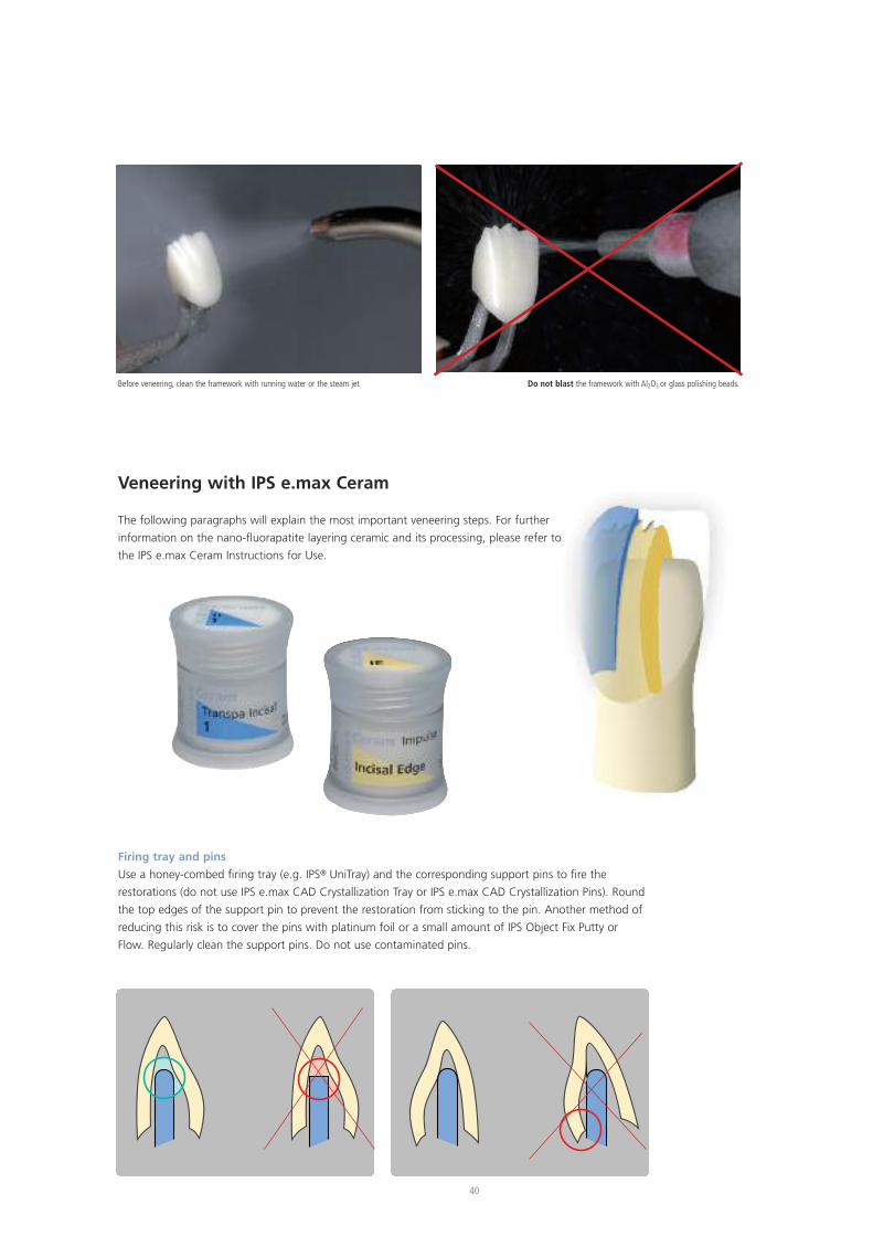
Veneering with IPS e.max Ceram
The following paragraphs will explain the most important veneering steps. For further
information on the nano-fluorapatite layering ceramic and its processing, please refer to
the IPS e.max Ceram Instructions for Use.
Firing tray and pins
Use a honey-combed firing tray (e.g. IPS® UniTray) and the corresponding support pins to fire the
restorations (do not use IPS e.max CAD Crystallization Tray or IPS e.max CAD Crystallization Pins). Round
the top edges of the support pin to prevent the restoration from sticking to the pin. Another method of
reducing this risk is to cover the pins with platinum foil or a small amount of IPS Object Fix Putty or
Flow. Regularly clean the support pins. Do not use contaminated pins.
Before veneering, clean the framework with running water or the steam jet Do not blast the framework with Al2O3 or glass polishing beads.
41
Cu
t-B
ack
Tech
niq
ue
Firing parameters for the Wash firing (foundation firing)
IPS e.max Ceram on IPS e.max CAD B S t� T H V1 V2
Cut-Back Technique [°C/°F] [min] [°C/°F/min] [°C/°F] [min] [°C/°F] [°C/°F]
Wash firing (foundation) 403/757 4:00 50/90 750/1382 1:00 450/842 749/1380
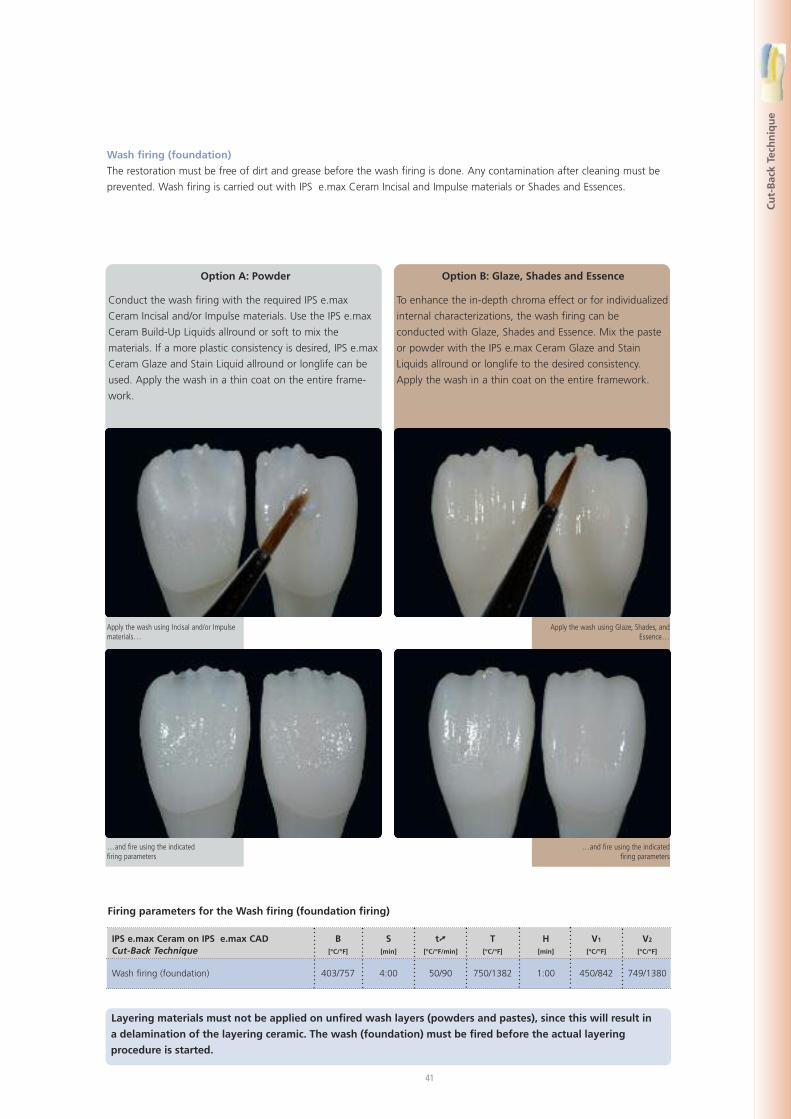
Wash firing (foundation)
The restoration must be free of dirt and grease before the wash firing is done. Any contamination after cleaning must be
prevented. Wash firing is carried out with IPS e.max Ceram Incisal and Impulse materials or Shades and Essences.
Option A: Powder
Conduct the wash firing with the required IPS e.max
Ceram Incisal and/or Impulse materials. Use the IPS e.max
Ceram Build-Up Liquids allround or soft to mix the
materials. If a more plastic consistency is desired, IPS e.max
Ceram Glaze and Stain Liquid allround or longlife can be
used. Apply the wash in a thin coat on the entire frame-
work.
Option B: Glaze, Shades and Essence
To enhance the in-depth chroma effect or for individualized
internal characterizations, the wash firing can be
conducted with Glaze, Shades and Essence. Mix the paste
or powder with the IPS e.max Ceram Glaze and Stain
Liquids allround or longlife to the desired consistency.
Apply the wash in a thin coat on the entire framework.
Apply the wash using Incisal and/or Impulsematerials…
…and fire using the indicatedfiring parameters
Apply the wash using Glaze, Shades, andEssence…
…and fire using the indicatedfiring parameters
Layering materials must not be applied on unfired wash layers (powders and pastes), since this will result in
a delamination of the layering ceramic. The wash (foundation) must be fired before the actual layering
procedure is started.
42
Firing parameters for the Incisal firing
IPS e.max Ceram on IPS e.max CAD B S t� T H V1 V2
Cut-Back Technique [°C/°F] [min] [°C/°F/min] [°C/°F] [min] [°C/°F] [°C/°F]
Incisal firing 403/757 4:00 50/90 750/1382 1:00 450/842 749/1380
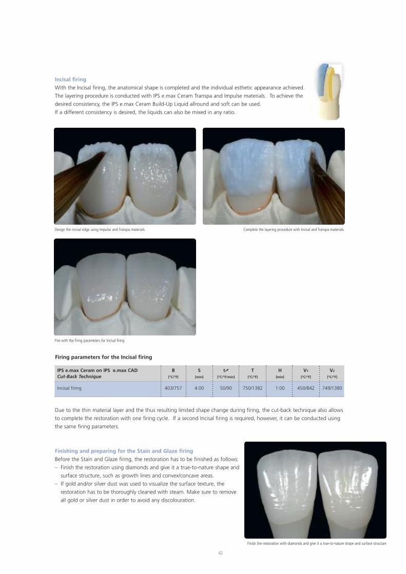
Incisal firing
With the Incisal firing, the anatomical shape is completed and the individual esthetic appearance achieved.
The layering procedure is conducted with IPS e.max Ceram Transpa and Impulse materials. To achieve the
desired consistency, the IPS e.max Ceram Build-Up Liquid allround and soft can be used.
If a different consistency is desired, the liquids can also be mixed in any ratio.
Design the incisal edge using Impulse and Transpa materials Complete the layering procedure with Incisal and Transpa materials
Fire with the firing parameters for Incisal firing
Due to the thin material layer and the thus resulting limited shape change during firing, the cut-back technique also allows
to complete the restoration with one firing cycle. If a second Incisal firing is required, however, it can be conducted using
the same firing parameters.
Finishing and preparing for the Stain and Glaze firing
Before the Stain and Glaze firing, the restoration has to be finished as follows:
– Finish the restoration using diamonds and give it a true-to-nature shape and
surface structure, such as growth lines and convex/concave areas.
– If gold and/or silver dust was used to visualize the surface texture, the
restoration has to be thoroughly cleaned with steam. Make sure to remove
all gold or silver dust in order to avoid any discolouration.
Finish the restoration with diamonds and give it a true-to-nature shape and surface structure
43
Cu
t-B
ack
Tech
niq
ue
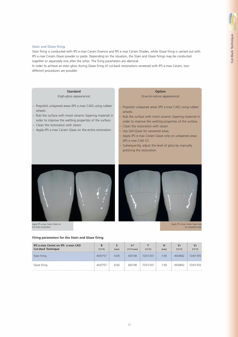
Stain and Glaze firing
Stain firing is conducted with IPS e.max Ceram Essence and IPS e.max Ceram Shades, while Glaze firing is carried out with
IPS e.max Ceram Glaze powder or paste. Depending on the situation, the Stain and Glaze firings may be conducted
together or separately one after the other. The firing parameters are identical.
In order to achieve an even gloss during Glaze firing of cut-back restorations veneered with IPS e.max Ceram, two
different procedures are possible:
Standard
(high-gloss appearance)
– Prepolish unlayered areas (IPS e.max CAD) using rubber
wheels.
– Rub the surface with moist ceramic (layering material) in
order to improve the wetting properties of the surface.
– Clean the restoration with steam.
– Apply IPS e.max Ceram Glaze on the entire restoration.
Option
(true-to-nature appearance)
– Prepolish unlayered areas (IPS e.max CAD) using rubber
wheels.
– Rub the surface with moist ceramic (layering material) in
order to improve the wetting properties of the surface.
– Clean the restoration with steam.
– Use Self-Glaze for veneered areas.
– Apply IPS e.max Ceram Glaze only on unlayered areas
(IPS e.max CAD LT).
– Subsequently, adjust the level of gloss by manually
polishing the restoration.
Apply IPS e.max Ceram Glaze onthe entire restoration
Apply IPS e.max Ceram Glaze onlyon unlayered areas
Firing parameters for the Stain and Glaze firing
IPS e.max Ceram on IPS e.max CAD B S t� T H V1 V2
Cut-Back Technique [°C/°F] [min] [°C/°F/min] [°C/°F] [min] [°C/°F] [°C/°F]
Stain firing 403/757 6:00 60/108 725/1337 1:00 450/842 724/1335
Glaze firing 403/757 6:00 60/108 725/1337 1:00 450/842 724/1335
44
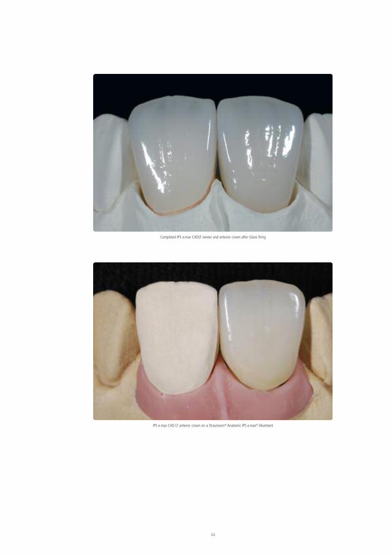
Completed IPS e.max CADLT veneer and anterior crown after Glaze firing
IPS e.max CAD LT anterior crown on a Straumann® Anatomic IPS e.max® Abutment
45
Laye
rin
gTe
chn
iqu
e
e.max® CAD –Layering Technique
IPS
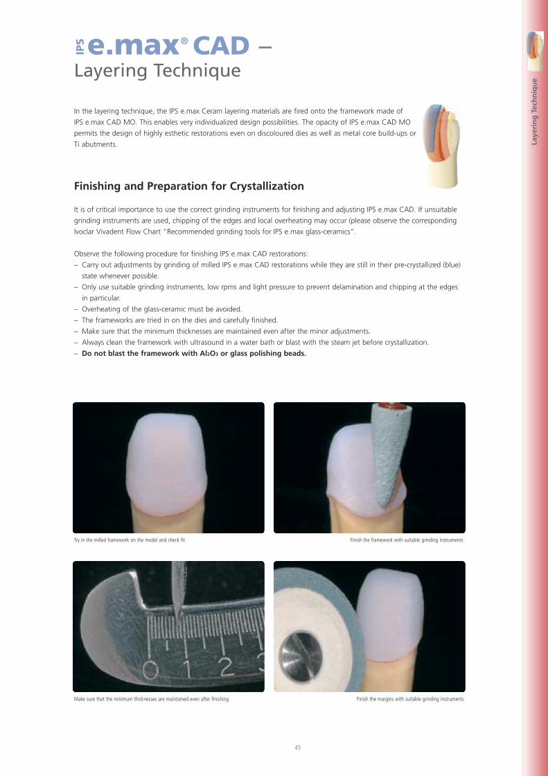
In the layering technique, the IPS e.max Ceram layering materials are fired onto the framework made of
IPS e.max CAD MO. This enables very individualized design possibilities. The opacity of IPS e.max CAD MO
permits the design of highly esthetic restorations even on discoloured dies as well as metal core build-ups or
Ti abutments.
Finishing and Preparation for Crystallization
It is of critical importance to use the correct grinding instruments for finishing and adjusting IPS e.max CAD. If unsuitable
grinding instruments are used, chipping of the edges and local overheating may occur (please observe the corresponding
Ivoclar Vivadent Flow Chart ”Recommended grinding tools for IPS e.max glass-ceramics”.
Observe the following procedure for finishing IPS e.max CAD restorations:
– Carry out adjustments by grinding of milled IPS e.max CAD restorations while they are still in their pre-crystallized (blue)
state whenever possible.
– Only use suitable grinding instruments, low rpms and light pressure to prevent delamination and chipping at the edges
in particular.
– Overheating of the glass-ceramic must be avoided.
– The frameworks are tried in on the dies and carefully finished.
– Make sure that the minimum thicknesses are maintained even after the minor adjustments.
– Always clean the framework with ultrasound in a water bath or blast with the steam jet before crystallization.
– Do not blast the framework with Al2O3 or glass polishing beads.
Try in the milled framework on the model and check fit Finish the framework with suitable grinding instruments
Make sure that the minimum thicknesses are maintained even after finishing Finish the margins with suitable grinding instruments
46
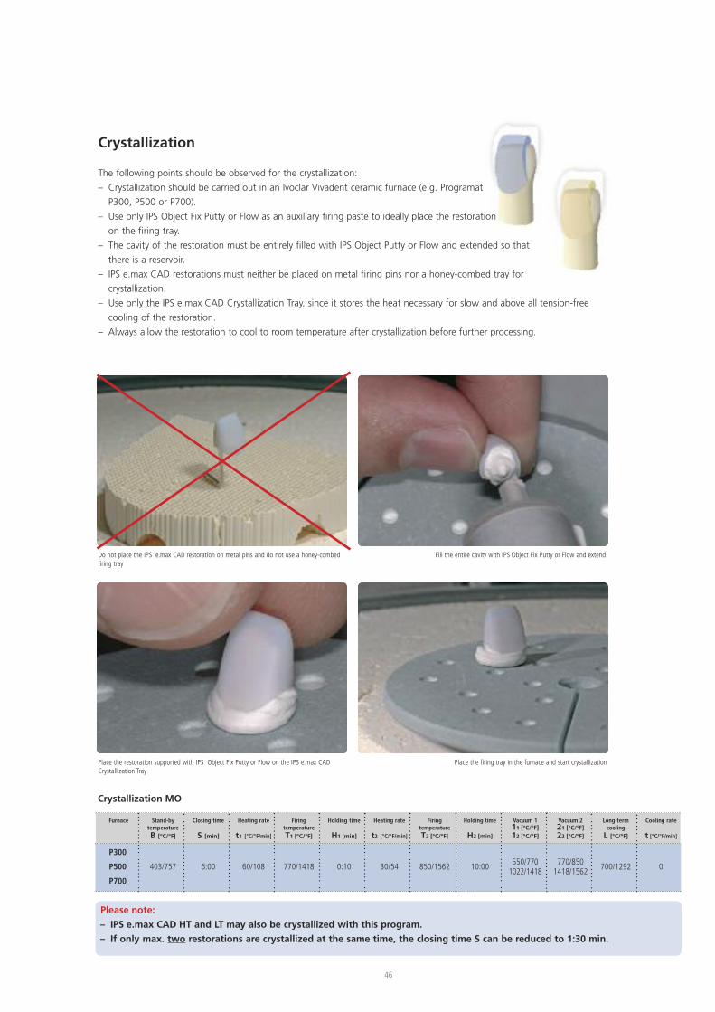
Crystallization
The following points should be observed for the crystallization:
– Crystallization should be carried out in an Ivoclar Vivadent ceramic furnace (e.g. Programat
P300, P500 or P700).
– Use only IPS Object Fix Putty or Flow as an auxiliary firing paste to ideally place the restoration
on the firing tray.
– The cavity of the restoration must be entirely filled with IPS Object Putty or Flow and extended so that
there is a reservoir.
– IPS e.max CAD restorations must neither be placed on metal firing pins nor a honey-combed tray for
crystallization.
– Use only the IPS e.max CAD Crystallization Tray, since it stores the heat necessary for slow and above all tension-free
cooling of the restoration.
– Always allow the restoration to cool to room temperature after crystallization before further processing.
Do not place the IPS e.max CAD restoration on metal pins and do not use a honey-combedfiring tray
Fill the entire cavity with IPS Object Fix Putty or Flow and extend
Place the restoration supported with IPS Object Fix Putty or Flow on the IPS e.max CADCrystallization Tray
Place the firing tray in the furnace and start crystallization
Furnace
P300
P500
P700
Stand-bytemperatureB [°C/°F]
403/757
Closing time
S [min]
6:00
Heating rate
t1 [°C/°F/min]
60/108
FiringtemperatureT1 [°C/°F]
770/1418
Holding time
H1 [min]
0:10
Heating rate
t2 [°C/°F/min]
30/54
FiringtemperatureT2 [°C/°F]
850/1562
Holding time
H2 [min]
10:00
Vacuum 111 [°C/°F]12 [°C/°F]
550/7701022/1418
Vacuum 221 [°C/°F]22 [°C/°F]
770/8501418/1562
Long-termcooling
L [°C/°F]
700/1292
Cooling rate
t [°C/°F/min]
0
Crystallization MO
Please note:
– IPS e.max CAD HT and LT may also be crystallized with this program.
– If only max. two restorations are crystallized at the same time, the closing time S can be reduced to 1:30 min.
47
Laye
rin
gTe
chn
iqu
e
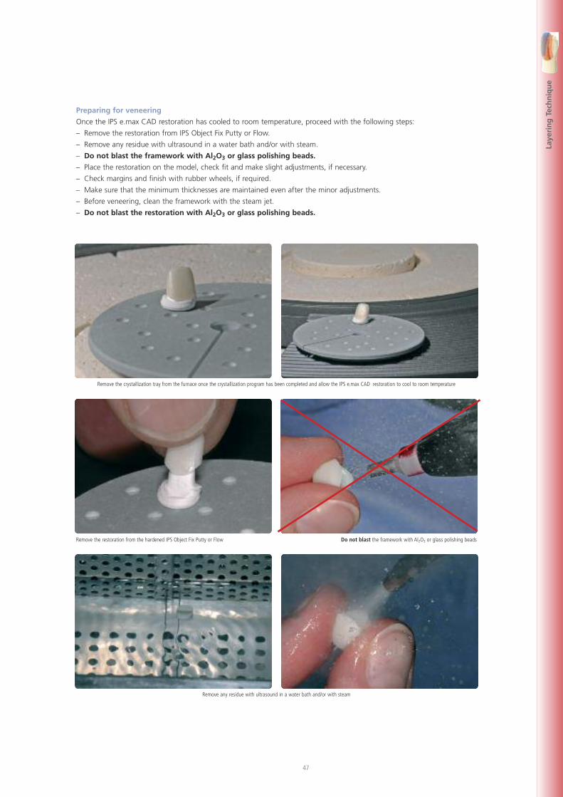
Preparing for veneering
Once the IPS e.max CAD restoration has cooled to room temperature, proceed with the following steps:
– Remove the restoration from IPS Object Fix Putty or Flow.
– Remove any residue with ultrasound in a water bath and/or with steam.
– Do not blast the framework with Al2O3 or glass polishing beads.
– Place the restoration on the model, check fit and make slight adjustments, if necessary.
– Check margins and finish with rubber wheels, if required.
– Make sure that the minimum thicknesses are maintained even after the minor adjustments.
– Before veneering, clean the framework with the steam jet.
– Do not blast the restoration with Al2O3 or glass polishing beads.
Remove the crystallization tray from the furnace once the crystallization program has been completed and allow the IPS e.max CAD restoration to cool to room temperature
Remove the restoration from the hardened IPS Object Fix Putty or Flow Do not blast the framework with Al2O3 or glass polishing beads
Remove any residue with ultrasound in a water bath and/or with steam
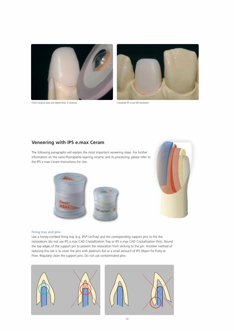
Check marginal areas and slightly finish, if necessary Completed IPS e.max MO framework
48
Veneering with IPS e.max Ceram
The following paragraphs will explain the most important veneering steps. For further
information on the nano-fluorapatite layering ceramic and its processing, please refer to
the IPS e.max Ceram Instructions for Use.
Firing tray and pins
Use a honey-combed firing tray (e.g. IPS® UniTray) and the corresponding support pins to fire the
restorations (do not use IPS e.max CAD Crystallization Tray or IPS e.max CAD Crystallization Pins). Round
the top edges of the support pin to prevent the restoration from sticking to the pin. Another method of
reducing this risk is to cover the pins with platinum foil or a small amount of IPS Object Fix Putty or
Flow. Regularly clean the support pins. Do not use contaminated pins.
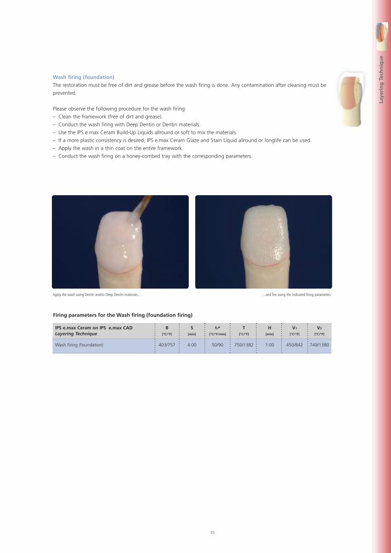
49
Laye
rin
gTe
chn
iqu
e
Wash firing (foundation)
The restoration must be free of dirt and grease before the wash firing is done. Any contamination after cleaning must be
prevented.
Please observe the following procedure for the wash firing:
– Clean the framework (free of dirt and grease).
– Conduct the wash firing with Deep Dentin or Dentin materials.
– Use the IPS e.max Ceram Build-Up Liquids allround or soft to mix the materials.
– If a more plastic consistency is desired, IPS e.max Ceram Glaze and Stain Liquid allround or longlife can be used.
– Apply the wash in a thin coat on the entire framework.
– Conduct the wash firing on a honey-combed tray with the corresponding parameters.
Apply the wash using Dentin and/or Deep Dentin materials… …and fire using the indicated firing parameters
Firing parameters for the Wash firing (foundation firing)
IPS e.max Ceram on IPS e.max CAD B S t� T H V1 V2
Layering Technique [°C/°F] [min] [°C/°F/min] [°C/°F] [min] [°C/°F] [°C/°F]
Wash firing (foundation) 403/757 4:00 50/90 750/1382 1:00 450/842 749/1380
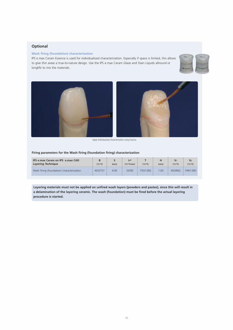
Optional
Wash firing (foundation) characterization
IPS e.max Ceram Essence is used for individualized characterization. Especially if space is limited, this allows
to give thin areas a true-to-nature design. Use the IPS e.max Ceram Glaze and Stain Liquids allround or
longlife to mix the materials.
Layering materials must not be applied on unfired wash layers (powders and pastes), since this will result in
a delamination of the layering ceramic. The wash (foundation) must be fired before the actual layering
procedure is started.
Apply individualized characterization using Essence.
50
Firing parameters for the Wash firing (foundation firing) characterization
IPS e.max Ceram on IPS e.max CAD B S t� T H V1 V2
Layering Technique [°C/°F] [min] [°C/°F/min] [°C/°F] [min] [°C/°F] [°C/°F]
Wash firing (foundation) characterization 403/757 4:00 50/90 750/1382 1:00 450/842 749/1380
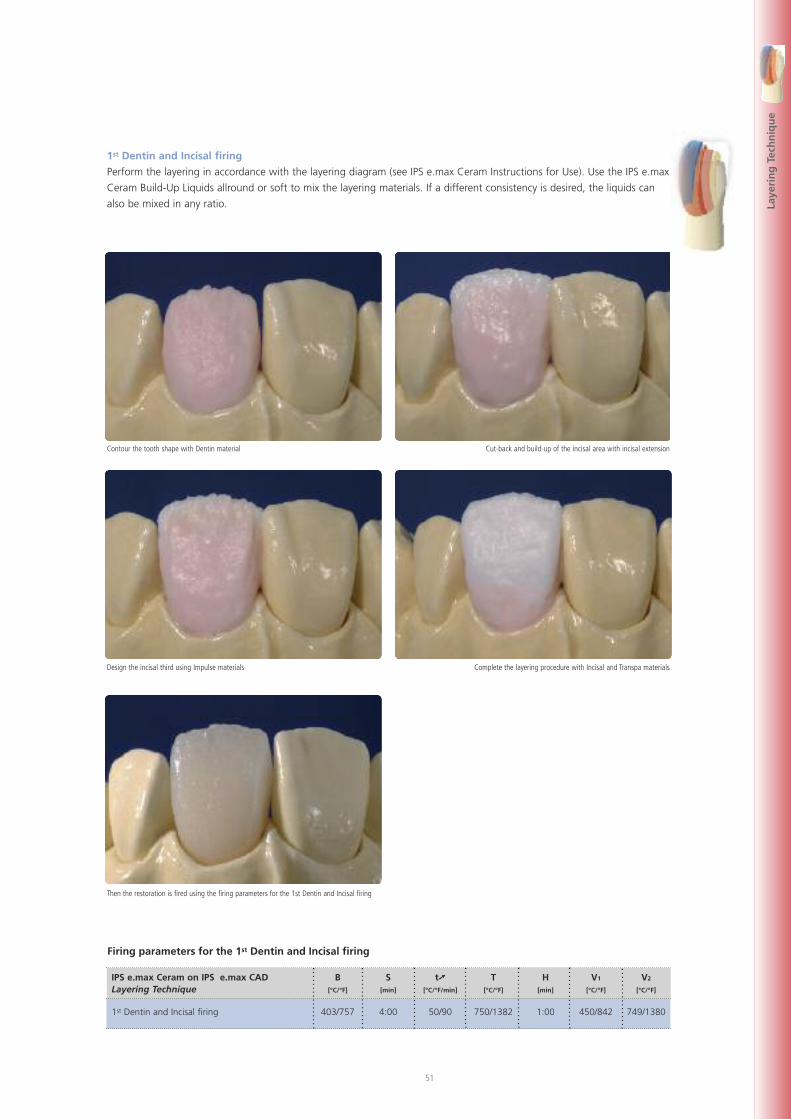
51
Laye
rin
gTe
chn
iqu
e
1st Dentin and Incisal firing
Perform the layering in accordance with the layering diagram (see IPS e.max Ceram Instructions for Use). Use the IPS e.max
Ceram Build-Up Liquids allround or soft to mix the layering materials. If a different consistency is desired, the liquids can
also be mixed in any ratio.
Contour the tooth shape with Dentin material Cut-back and build-up of the incisal area with incisal extension
Design the incisal third using Impulse materials Complete the layering procedure with Incisal and Transpa materials
Then the restoration is fired using the firing parameters for the 1st Dentin and Incisal firing
Firing parameters for the 1st Dentin and Incisal firing
IPS e.max Ceram on IPS e.max CAD B S t� T H V1 V2
Layering Technique [°C/°F] [min] [°C/°F/min] [°C/°F] [min] [°C/°F] [°C/°F]
1st Dentin and Incisal firing 403/757 4:00 50/90 750/1382 1:00 450/842 749/1380
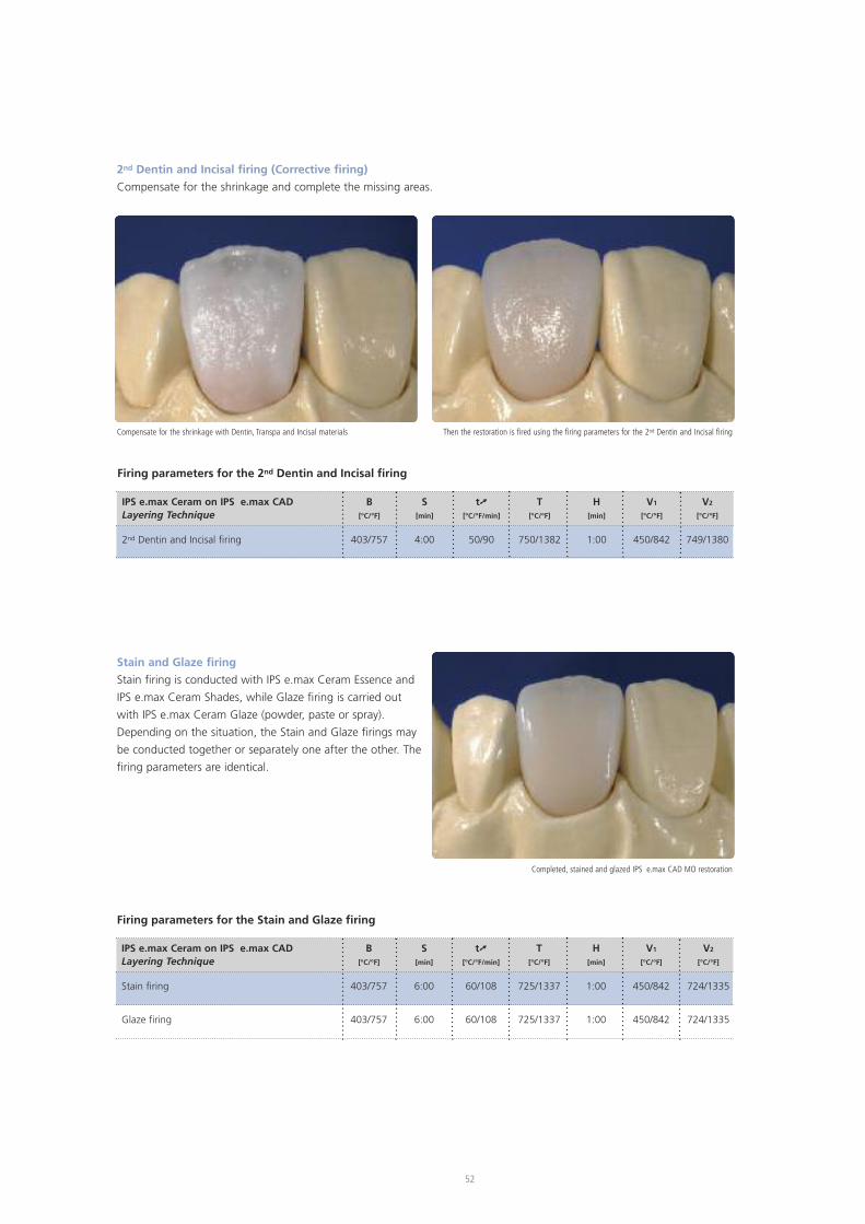
2nd Dentin and Incisal firing (Corrective firing)
Compensate for the shrinkage and complete the missing areas.
Stain and Glaze firing
Stain firing is conducted with IPS e.max Ceram Essence and
IPS e.max Ceram Shades, while Glaze firing is carried out
with IPS e.max Ceram Glaze (powder, paste or spray).
Depending on the situation, the Stain and Glaze firings may
be conducted together or separately one after the other. The
firing parameters are identical.
Compensate for the shrinkage with Dentin, Transpa and Incisal materials
Completed, stained and glazed IPS e.max CAD MO restoration
Then the restoration is fired using the firing parameters for the 2nd Dentin and Incisal firing
52
Firing parameters for the 2nd Dentin and Incisal firing
IPS e.max Ceram on IPS e.max CAD B S t� T H V1 V2
Layering Technique [°C/°F] [min] [°C/°F/min] [°C/°F] [min] [°C/°F] [°C/°F]
2nd Dentin and Incisal firing 403/757 4:00 50/90 750/1382 1:00 450/842 749/1380
Firing parameters for the Stain and Glaze firing
IPS e.max Ceram on IPS e.max CAD B S t� T H V1 V2
Layering Technique [°C/°F] [min] [°C/°F/min] [°C/°F] [min] [°C/°F] [°C/°F]
Stain firing 403/757 6:00 60/108 725/1337 1:00 450/842 724/1335
Glaze firing 403/757 6:00 60/108 725/1337 1:00 450/842 724/1335
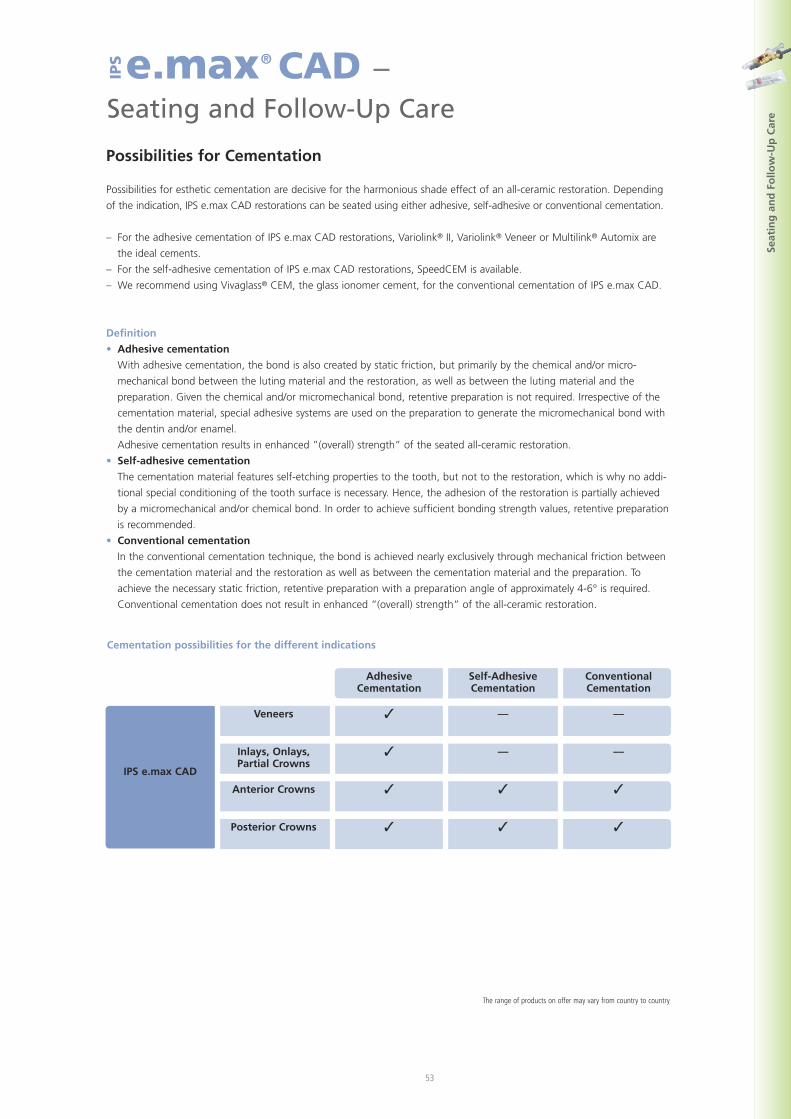
53
Seat
ing
and
Follo
w-U
pC
are
e.max® CAD –Seating and Follow-Up Care
IPS
Possibilities for Cementation
Possibilities for esthetic cementation are decisive for the harmonious shade effect of an all-ceramic restoration. Depending
of the indication, IPS e.max CAD restorations can be seated using either adhesive, self-adhesive or conventional cementation.
– For the adhesive cementation of IPS e.max CAD restorations, Variolink® II, Variolink® Veneer or Multilink® Automix are
the ideal cements.
– For the self-adhesive cementation of IPS e.max CAD restorations, SpeedCEM is available.
– We recommend using Vivaglass® CEM, the glass ionomer cement, for the conventional cementation of IPS e.max CAD.
Definition
• Adhesive cementation
With adhesive cementation, the bond is also created by static friction, but primarily by the chemical and/or micro-
mechanical bond between the luting material and the restoration, as well as between the luting material and the
preparation. Given the chemical and/or micromechanical bond, retentive preparation is not required. Irrespective of the
cementation material, special adhesive systems are used on the preparation to generate the micromechanical bond with
the dentin and/or enamel.
Adhesive cementation results in enhanced ”(overall) strength” of the seated all-ceramic restoration.
• Self-adhesive cementation
The cementation material features self-etching properties to the tooth, but not to the restoration, which is why no addi-
tional special conditioning of the tooth surface is necessary. Hence, the adhesion of the restoration is partially achieved
by a micromechanical and/or chemical bond. In order to achieve sufficient bonding strength values, retentive preparation
is recommended.
• Conventional cementation
In the conventional cementation technique, the bond is achieved nearly exclusively through mechanical friction between
the cementation material and the restoration as well as between the cementation material and the preparation. To
achieve the necessary static friction, retentive preparation with a preparation angle of approximately 4-6° is required.
Conventional cementation does not result in enhanced ”(overall) strength” of the all-ceramic restoration.
�Veneers
IPS e.max CAD
–– ––
�Inlays, Onlays,Partial Crowns
–– ––
�Anterior Crowns � �
�Posterior Crowns � �
AdhesiveCementation
Self-AdhesiveCementation
ConventionalCementation
Cementation possibilities for the different indications
The range of products on offer may vary from country to country
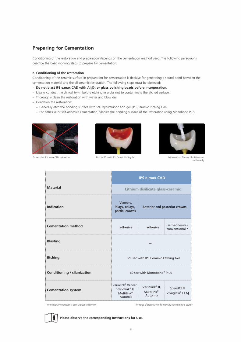
54
Do not blast IPS e.max CAD restorations Etch for 20 s with IPS Ceramic Etching Gel Let Monobond Plus react for 60 secondsand blow dry
* Conventional cementation is done without conditioning The range of products on offer may vary from country to country
Please observe the corresponding Instructions for Use.
Material
Indication
Cementation method
Blasting
Etching
Conditioning / silanization
Cementation system
self-adhesive /conventional *
Variolink® II,
Multilink®
Automix
SpeedCEM
Vivaglass® CEM
IPS e.max CAD
Veneers,inlays, onlays,partial crowns
Anterior and posterior crowns
adhesive adhesive
20 sec with IPS Ceramic Etching Gel
60 sec with Monobond® Plus
––
Variolink® Veneer,Variolink® II,
Multilink®
Automix
Lithium disilicate glass-ceramic
Preparing for Cementation
Conditioning of the restoration and preparation depends on the cementation method used. The following paragraphs
describe the basic working steps to prepare for cementation.
a. Conditioning of the restoration
Conditioning of the ceramic surface in preparation for cementation is decisive for generating a sound bond between the
cementation material and the all-ceramic restoration. The following steps must be observed:
– Do not blast IPS e.max CAD with Al2O3 or glass polishing beads before incorporation.
– Ideally, conduct the clinical try-in before etching in order not to contaminate the etched surface.
– Thoroughly clean the restoration with water and blow dry.
– Condition the restoration:
– Generally etch the bonding surface with 5% hydrofluoric acid gel (IPS Ceramic Etching Gel).
– For adhesive or self-adhesive cementation, silanize the bonding surface of the restoration using Monobond Plus.
**
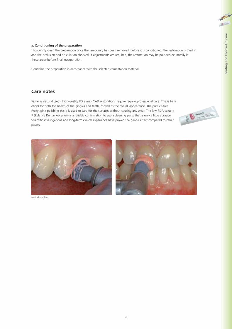
55
Seat
ing
and
Follo
w-U
pC
are
a. Conditioning of the preparation
Thoroughly clean the preparation once the temporary has been removed. Before it is conditioned, the restoration is tried in
and the occlusion and articulation checked. If adjustments are required, the restoration may be polished extraorally in
these areas before final incorporation.
Condition the preparation in accordance with the selected cementation material.
Care notes
Same as natural teeth, high-quality IPS e.max CAD restorations require regular professional care. This is ben-
eficial for both the health of the gingiva and teeth, as well as the overall appearance. The pumice-free
Proxyt pink polishing paste is used to care for the surfaces without causing any wear. The low RDA value =
7 (Relative Dentin Abrasion) is a reliable confirmation to use a cleaning paste that is only a little abrasive.
Scientific investigations and long-term clinical experience have proved the gentle effect compared to other
pastes.
Application of Proxyt
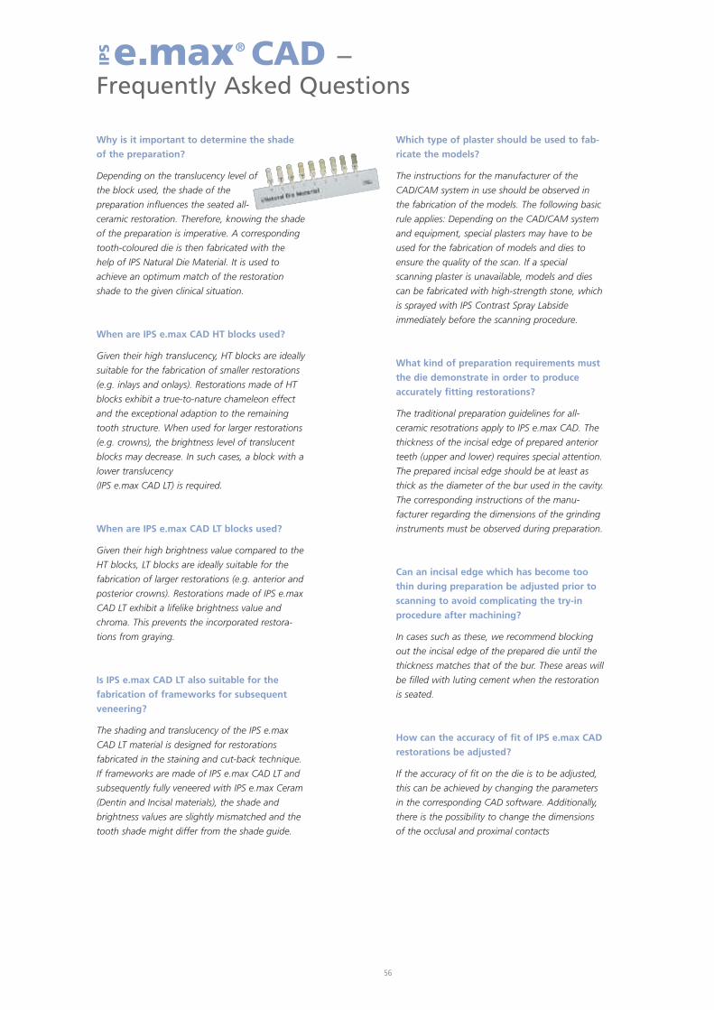
Why is it important to determine the shade
of the preparation?
Depending on the translucency level of
the block used, the shade of the
preparation influences the seated all-
ceramic restoration. Therefore, knowing the shade
of the preparation is imperative. A corresponding
tooth-coloured die is then fabricated with the
help of IPS Natural Die Material. It is used to
achieve an optimum match of the restoration
shade to the given clinical situation.
When are IPS e.max CAD HT blocks used?
Given their high translucency, HT blocks are ideally
suitable for the fabrication of smaller restorations
(e.g. inlays and onlays). Restorations made of HT
blocks exhibit a true-to-nature chameleon effect
and the exceptional adaption to the remaining
tooth structure. When used for larger restorations
(e.g. crowns), the brightness level of translucent
blocks may decrease. In such cases, a block with a
lower translucency
(IPS e.max CAD LT) is required.
When are IPS e.max CAD LT blocks used?
Given their high brightness value compared to the
HT blocks, LT blocks are ideally suitable for the
fabrication of larger restorations (e.g. anterior and
posterior crowns). Restorations made of IPS e.max
CAD LT exhibit a lifelike brightness value and
chroma. This prevents the incorporated restora-
tions from graying.
Is IPS e.max CAD LT also suitable for the
fabrication of frameworks for subsequent
veneering?
The shading and translucency of the IPS e.max
CAD LT material is designed for restorations
fabricated in the staining and cut-back technique.
If frameworks are made of IPS e.max CAD LT and
subsequently fully veneered with IPS e.max Ceram
(Dentin and Incisal materials), the shade and
brightness values are slightly mismatched and the
tooth shade might differ from the shade guide.
Which type of plaster should be used to fab-
ricate the models?
The instructions for the manufacturer of the
CAD/CAM system in use should be observed in
the fabrication of the models. The following basic
rule applies: Depending on the CAD/CAM system
and equipment, special plasters may have to be
used for the fabrication of models and dies to
ensure the quality of the scan. If a special
scanning plaster is unavailable, models and dies
can be fabricated with high-strength stone, which
is sprayed with IPS Contrast Spray Labside
immediately before the scanning procedure.
What kind of preparation requirements must
the die demonstrate in order to produce
accurately fitting restorations?
The traditional preparation guidelines for all-
ceramic resotrations apply to IPS e.max CAD. The
thickness of the incisal edge of prepared anterior
teeth (upper and lower) requires special attention.
The prepared incisal edge should be at least as
thick as the diameter of the bur used in the cavity.
The corresponding instructions of the manu-
facturer regarding the dimensions of the grinding
instruments must be observed during preparation.
Can an incisal edge which has become too
thin during preparation be adjusted prior to
scanning to avoid complicating the try-in
procedure after machining?
In cases such as these, we recommend blocking
out the incisal edge of the prepared die until the
thickness matches that of the bur. These areas will
be filled with luting cement when the restoration
is seated.
How can the accuracy of fit of IPS e.max CAD
restorations be adjusted?
If the accuracy of fit on the die is to be adjusted,
this can be achieved by changing the parameters
in the corresponding CAD software. Additionally,
there is the possibility to change the dimensions
of the occlusal and proximal contacts
56
e.max® CAD –Frequently Asked Questions
IPS
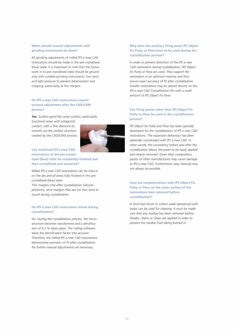
57
When should manual adjustments with
grinding instruments be done?
All grinding adjustments of milled IPS e.max CAD
restorations should be made in the pre-crystallized
(blue) state. It is important to note that the frame-
work in its pre-crystallized state should be ground
only with suitable grinding instruments, low rpms
and light pressure to prevent delamination and
chipping, particularly at the margins.
Do IPS e.max CAD restorations require
occlusal adjustment after the CAD/CAM
process?
Yes. Surface-grind the outer surface, particularly
functional areas with antagonist
contact, with a fine diamond to
smooth out the surface structure
created by the CAD/CAM process.
Can machined IPS e.max CAD
restorations in the pre-crystal-
lized (blue) state be completely finished and
then crystallized and veneered?
Milled IPS e.max CAD restorations can be tried in
on the die and all areas fully finished in the pre-
crystallized (blue) state.
Thin margins only after crystallization (silicone
polishers), since margins that are too thin tend to
round during crystallization.
Do IPS e.max CAD restorations shrink during
crystallization?
No. During the crystallization process, the micro-
structure becomes transformed and a densifica-
tion of 0.2 % takes place. The milling software
takes the densification factor into account.
Therefore, the milled IPS e.max CAD restorations
demonstrate precision of fit after crystallization.
No further manual adjustments are necessary.
Why does the auxiliary firing paste IPS Object
Fix Putty or Flow have to be used during the
crystallization process?
In order to prevent distortion of the IPS e.max
CAD restoration during crystallization, IPS Object
Fix Putty or Flow are used. They support the
restoration in an optimum manner and thus
ensure exact accuracy of fit after crystallization.
Smaller restorations may be placed directly on the
IPS e.max CAD Crystallization Pin with a small
amount of IPS Object Fix Flow.
Can firing pastes other than IPS Object Fix
Putty or Flow be used in the crystallization
process?
IPS Object Fix Putty and Flow has been specially
developed for the crystallization of IPS e.max CAD
restorations. The expansion behaviour has been
optimally coordinated with IPS e.max CAD. In
other words, the consistency before and after the
crystallization allows the paste to be easily applied
and cleanly removed. Given their composition,
pastes of other manufacturers may cause damage
to IPS e.max CAD. Furthermore, easy removal may
not always be possible.
How are contaminations with IPS Object Fix
Putty or Flow on the outer surface of the
restorations best removed before
crystallization?
A short-hair brush or cotton swab dampened with
water can be used for cleaning. It must be made
sure that any residue has been removed before
Shades, Stains or Glaze are applied in order to
prevent the residue from being burned in.
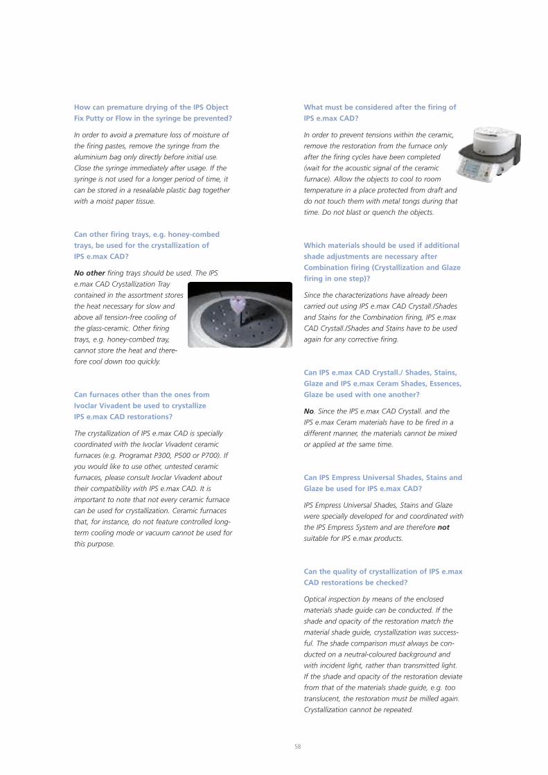
How can premature drying of the IPS Object
Fix Putty or Flow in the syringe be prevented?
In order to avoid a premature loss of moisture of
the firing pastes, remove the syringe from the
aluminium bag only directly before initial use.
Close the syringe immediately after usage. If the
syringe is not used for a longer period of time, it
can be stored in a resealable plastic bag together
with a moist paper tissue.
Can other firing trays, e.g. honey-combed
trays, be used for the crystallization of
IPS e.max CAD?
No other firing trays should be used. The IPS
e.max CAD Crystallization Tray
contained in the assortment stores
the heat necessary for slow and
above all tension-free cooling of
the glass-ceramic. Other firing
trays, e.g. honey-combed tray,
cannot store the heat and there-
fore cool down too quickly.
Can furnaces other than the ones from
Ivoclar Vivadent be used to crystallize
IPS e.max CAD restorations?
The crystallization of IPS e.max CAD is specially
coordinated with the Ivoclar Vivadent ceramic
furnaces (e.g. Programat P300, P500 or P700). If
you would like to use other, untested ceramic
furnaces, please consult Ivoclar Vivadent about
their compatibility with IPS e.max CAD. It is
important to note that not every ceramic furnace
can be used for crystallization. Ceramic furnaces
that, for instance, do not feature controlled long-
term cooling mode or vacuum cannot be used for
this purpose.
What must be considered after the firing of
IPS e.max CAD?
In order to prevent tensions within the ceramic,
remove the restoration from the furnace only
after the firing cycles have been completed
(wait for the acoustic signal of the ceramic
furnace). Allow the objects to cool to room
temperature in a place protected from draft and
do not touch them with metal tongs during that
time. Do not blast or quench the objects.
Which materials should be used if additional
shade adjustments are necessary after
Combination firing (Crystallization and Glaze
firing in one step)?
Since the characterizations have already been
carried out using IPS e.max CAD Crystall./Shades
and Stains for the Combination firing, IPS e.max
CAD Crystall./Shades and Stains have to be used
again for any corrective firing.
Can IPS e.max CAD Crystall./ Shades, Stains,
Glaze and IPS e.max Ceram Shades, Essences,
Glaze be used with one another?
No. Since the IPS e.max CAD Crystall. and the
IPS e.max Ceram materials have to be fired in a
different manner, the materials cannot be mixed
or applied at the same time.
Can IPS Empress Universal Shades, Stains and
Glaze be used for IPS e.max CAD?
IPS Empress Universal Shades, Stains and Glaze
were specially developed for and coordinated with
the IPS Empress System and are therefore not
suitable for IPS e.max products.
Can the quality of crystallization of IPS e.max
CAD restorations be checked?
Optical inspection by means of the enclosed
materials shade guide can be conducted. If the
shade and opacity of the restoration match the
material shade guide, crystallization was success-
ful. The shade comparison must always be con-
ducted on a neutral-coloured background and
with incident light, rather than transmitted light.
If the shade and opacity of the restoration deviate
from that of the materials shade guide, e.g. too
translucent, the restoration must be milled again.
Crystallization cannot be repeated.
58
59
Can IPS e.max Ceram Margin materials be
used with IPS e.max CAD?
IPS e.max Ceram Margin materials must not be
used on glass-ceramics (IPS e.max Press and CAD),
since the reduction for the shoulder would
weaken the restoration.
Can IPS e.max CAD frameworks be blasted
with Al2O3 or glass polishing beads before
they are veneered or after their completion
(on the cavity side)?
IPS e.max CAD restorations must never be
blasted with Al2O3 or polishing beads, as this
would damage the ceramic surface and reduce
the outstanding physical properties.
How must the internal (bonding) surface
of the IPS e.max CAD restorations be
conditioned before cementation?
The internal (bonding) surfaces of IPS e.max CAD
restorations must always be etched with hydro-
fluoric acid etching gel (IPS Ceramic Etching Gel)
for 20 seconds, whether they are cemented with
adhesive, self-adhesive, or con-ventional methods.
The resulting retentive pattern enables an
enhanced bond both with adhesives and self-
adhesives as well as conventional bonding agents.
After etching, the glass-ceramics are silanized
using Monobond Plus when adhesive and self-
adhesive cementation is used. With conventional
cementation, silanizing is not necessary.
Can IPS e.max CAD restorations also be
conventionally cemented?
IPS e.max CAD restorations can be cemented
adhesively, self-adhesively or conventionally. If
the restoration is to be conventionally cemented,
however, an appropriately retentive preparation
design must be observed (preparation angle of
4°-6°). If this is not possible, adhesive luting is
preferred, e.g. Variolink® II and Multilink®
Automix.
It is not advisable to use classical phosphate
cements, as they would negatively influence the
light transmission of the all-ceramic and therefore
compromise the esthetic appearance of all-
ceramic restorations.
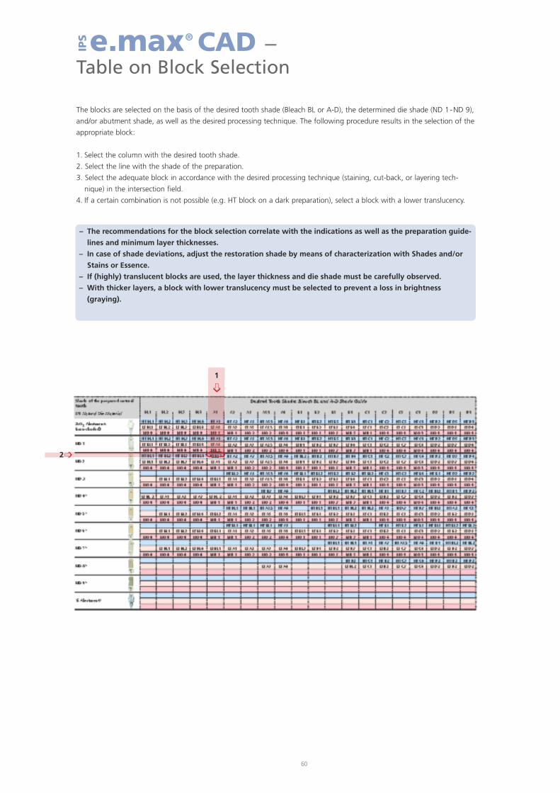
60
e.max® CAD –Table on Block Selection
IPS
The blocks are selected on the basis of the desired tooth shade (Bleach BL or A-D), the determined die shade (ND 1-ND 9),
and/or abutment shade, as well as the desired processing technique. The following procedure results in the selection of the
appropriate block:
1. Select the column with the desired tooth shade.
2. Select the line with the shade of the preparation.
3. Select the adequate block in accordance with the desired processing technique (staining, cut-back, or layering tech-
nique) in the intersection field.
4. If a certain combination is not possible (e.g. HT block on a dark preparation), select a block with a lower translucency.
2
1�
�
– The recommendations for the block selection correlate with the indications as well as the preparation guide-
lines and minimum layer thicknesses.
– In case of shade deviations, adjust the restoration shade by means of characterization with Shades and/or
Stains or Essence.
– If (highly) translucent blocks are used, the layer thickness and die shade must be carefully observed.
– With thicker layers, a block with lower translucency must be selected to prevent a loss in brightness
(graying).
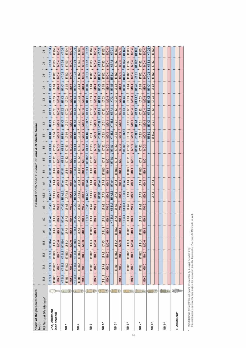
61
*With
MO
bloc
ks,the
brightne
ssan
dch
romaareco
ntrolle
dby
mea
nsof
thewas
hfiring.
Ifno
combina
tionis
possible,the
dark
shad
eof
theprep
arationsh
ould
bebrighten
edor
IPSe.max
CAD
MO
shou
ldbe
used
.
Shad
eo
fth
ep
rep
ared
nat
ura
lto
oth
IPSNaturalD
ieMaterial
BL1
BL2
BL3
BL4
A1
A2
A3
A3.5
A4
B1B2
B3B4
C1C2
C3C4
D2
D3
D4
Des
ired
Too
thSh
ade:BleachBLandA-D
ShadeGuide
HTBL1
HTBL2
HTBL3
HTBL4
HTA1
HTA2
HTA3
HTA3.5
HTA4
HTB1
HTB2
HTB3
HTB4
HTC1
HTC2
HTC3
HTC4
HTD2
HTD3
HTD4
LTBL1
LTBL2
LTBL3
LTBL4
LTA1
LTA2
LTA3
LTA3.5
LTA4
LTB1
LTB2
LTB3
LTB4
LTC1
LTC2
LTC3
LTC4
LTD2
LTD3
LTD4
MO0
MO0
MO0
MO0
MO1
MO1
MO2
MO2
MO4
MO1
MO1
MO3
MO3
MO1
MO4
MO4
MO4
MO4
MO4
MO4
HTBL1
HTBL2
HTBL3
HTBL4
HTA1
HTA2
HTA3
HTA3.5
HTA4
HTB1
HTB2
HTB3
HTB4
HTC1
HTC2
HTC3
HTC4
HTD2
HTD3
HTD4
LTBL1
LTBL2
LTBL3
LTBL4
LTA1
LTA2
LTA3
LTA3.5
LTA4
LTB1
LTB2
LTB3
LTB4
LTC1
LTC2
LTC3
LTC4
LTD2
LTD3
LTD4
MO0
MO0
MO0
MO0
MO1
MO1
MO2
MO2
MO4
MO1
MO1
MO3
MO3
MO1
MO4
MO4
MO4
MO4
MO4
MO4
HTBL1
HTBL2
HTBL3
HTBL4
HTBL2
HTA2
HTA3
HTA3.5
HTA4
HTBL2
HTB2
HTB3
HTB4
HTC1
HTC2
HTC3
HTC4
HTD2
HTD3
HTD4
LTBL1
LTBL2
LTBL3
LTBL4
LTA1
LTA2
LTA3
LTA3.5
LTA4
LTB1
LTB2
LTB3
LTB4
LTC1
LTC2
LTC3
LTC4
LTD2
LTD3
LTD4
MO0
MO0
MO0
MO0
MO1
MO1
MO2
MO2
MO4
MO1
MO1
MO3
MO3
MO1
MO4
MO4
MO4
MO4
MO4
MO4
HTBL2
HTA1
HTA3.5
HTA4
HTBL1
HTBL2
HTB2
HTB2
HTBL2
HTC1
HTC2
HTB4
HTB1
HTD2
HTD2
LTBL1
LTBL2
LTBL4
LTBL3
LTA1
LTA2
LTA3.5
LTA4
LTB1
LTB2
LTB3
LT4
LTC1
LTC2
LTC3
LTC4
LTD2
LTD3
LTD4
MO0
MO0
MO0
MO0
MO1
MO1
MO2
MO2
MO4
MO1
MO1
MO3
MO3
MO1
MO4
MO4
MO4
MO4
MO4
MO4
HTB3
HTA4
HTBL2
HTBL2
HTBL1
HTB1
HTB3
HTC2
HTBL1
HTB1
HTD2
LTBL
2LT
A1
LTA2
LTA3
LTBL
2LT
A1
LTA2
LTA3
LTA4
LTBL3
LTB1
LTB2
LTB3
LTC1
LTB2
LTC3
LTC4
LTD2
LTB2
LTD3
MO0
MO0
MO0
MO0
MO1
MO1
MO2
MO2
MO4
MO1
MO1
MO3
MO3
MO1
MO4
MO4
MO4
MO4
MO4
MO4
HTBL1
HTBL1
HTA3.5
HTA4
HTBL1
HTBL1
HTBL2
HTBL2
HTA1
HTA
3HTB3
HTBL1
HTA2
HTC1
LTBL1
LTBL2
LTBL4
LTBL2
LTA1
LTA2
LTA3
LTA4
LTBL3
LTB1
LTB2
LTB3
LTC1
LTB2
LTC3
LTC4
LTD2
LTB2
LTD3
MO0
MO0
MO0
MO0
MO1
MO1
MO2
MO2
MO4
MO1
MO1
MO3
MO3
MO1
MO4
MO4
MO4
MO4
MO4
MO4
HTBL1
HTBL1
HTBL1
HTA3
HTBL1
HTBL2
HTB1
HTB2
HTB3
HTBL1
HTBL2
HTBL2
LTBL1
LTBL2
LTBL4
LTBL1
LTA1
LTA2
LTA3
LTA4
LTBL3
LTB1
LTB2
LTB3
LTC1
LTB2
LTC3
LTC4
LTD2
LTB2
LTD3
MO0
MO0
MO0
MO0
MO1
MO1
MO2
MO2
MO4
MO1
MO1
MO3
MO3
MO1
MO4
MO4
MO4
MO4
MO4
MO4
HTBL1
HTBL1
HTA1
HTA3
HTA3.5
HTA4
HTB1
HTBL2
HTBL2
LTBL1
LTBL2
LTBL4
LTBL1
LTA1
LTA2
LTA3
LTA4
LTBL3
LTB1
LTB2
LTB3
LTC1
LTB2
LTC3
LTC4
LTD2
LTB2
LTD3
MO0
MO0
MO0
MO0
MO1
MO1
MO2
MO2
MO4
MO1
MO1
MO3
MO3
MO1
MO4
MO4
MO4
MO4
MO4
MO4
HTB2
HTC1
HTB2
HTC3
HTC4
HTD2
HTB2
HTD2
LTA3
LTA4
LTBL2
LTC1
LTB2
LTC3
LTC4
LTD2
LTB2
LTD2
ZrO
2A
bu
tmen
t(n
on
-sh
aded
)
ND
1
ND
2
ND
3
ND
4*
ND
5*
ND
6*
ND
7*
ND
8*
ND
9*
TiA
bu
tmen
t*
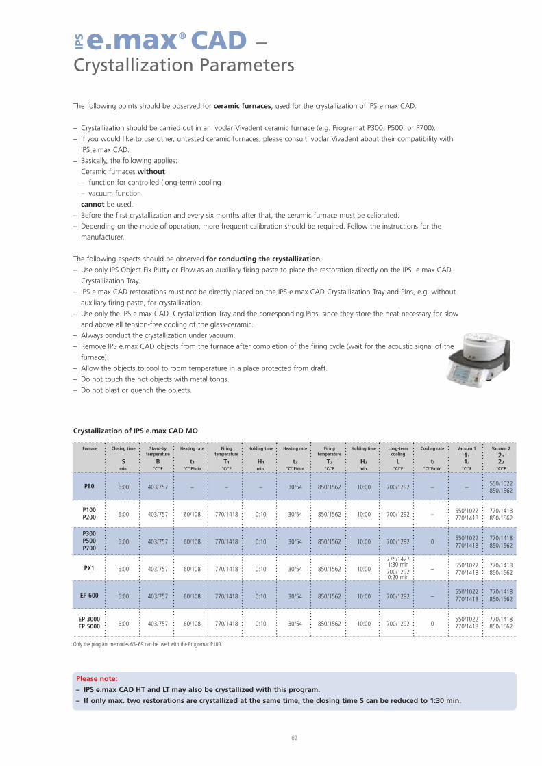
The following points should be observed for ceramic furnaces, used for the crystallization of IPS e.max CAD:
– Crystallization should be carried out in an Ivoclar Vivadent ceramic furnace (e.g. Programat P300, P500, or P700).
– If you would like to use other, untested ceramic furnaces, please consult Ivoclar Vivadent about their compatibility with
IPS e.max CAD.
– Basically, the following applies:
Ceramic furnaces without
– function for controlled (long-term) cooling
– vacuum function
cannot be used.
– Before the first crystallization and every six months after that, the ceramic furnace must be calibrated.
– Depending on the mode of operation, more frequent calibration should be required. Follow the instructions for the
manufacturer.
The following aspects should be observed for conducting the crystallization:
– Use only IPS Object Fix Putty or Flow as an auxiliary firing paste to place the restoration directly on the IPS e.max CAD
Crystallization Tray.
– IPS e.max CAD restorations must not be directly placed on the IPS e.max CAD Crystallization Tray and Pins, e.g. without
auxiliary firing paste, for crystallization.
– Use only the IPS e.max CAD Crystallization Tray and the corresponding Pins, since they store the heat necessary for slow
and above all tension-free cooling of the glass-ceramic.
– Always conduct the crystallization under vacuum.
– Remove IPS e.max CAD objects from the furnace after completion of the firing cycle (wait for the acoustic signal of the
furnace).
– Allow the objects to cool to room temperature in a place protected from draft.
– Do not touch the hot objects with metal tongs.
– Do not blast or quench the objects.
62
e.max® CAD –Crystallization Parameters
IPS
Furnace
P80
P100P200
P300P500P700
PX1
EP 600
EP 3000EP 5000
Closing time
Smin.
6:00
6:00
6:00
6:00
6:00
6:00
Stand-bytemperature
B°C/°F
403/757
403/757
403/757
403/757
403/757
403/757
Heating rate
t1
°C/°F/min
–
60/108
60/108
60/108
60/108
60/108
Firingtemperature
T1
°C/°F
–
770/1418
770/1418
770/1418
770/1418
770/1418
Holding time
H1
min.
–
0:10
0:10
0:10
0:10
0:10
Heating rate
t2
°C/°F/min
30/54
30/54
30/54
30/54
30/54
30/54
Firingtemperature
T2
°C/°F
850/1562
850/1562
850/1562
850/1562
850/1562
850/1562
Holding time
H2
min.
10:00
10:00
10:00
10:00
10:00
10:00
Long-termcooling
L°C/°F
700/1292
700/1292
700/1292
775/14271:30 min700/12920:20 min
700/1292
700/1292
Cooling rate
tl
°C/°F/min
–
–
0
–
–
0
Vacuum 1
11
12
°C/°F
–
550/1022770/1418
550/1022770/1418
550/1022770/1418
550/1022770/1418
550/1022770/1418
Vacuum 2
21
22
°C/°F
550/1022850/1562
770/1418850/1562
770/1418850/1562
770/1418850/1562
770/1418850/1562
770/1418850/1562
Crystallization of IPS e.max CAD MO
Only the program memories 65-69 can be used with the Programat P100.
Please note:
– IPS e.max CAD HT and LT may also be crystallized with this program.
– If only max. two restorations are crystallized at the same time, the closing time S can be reduced to 1:30 min.
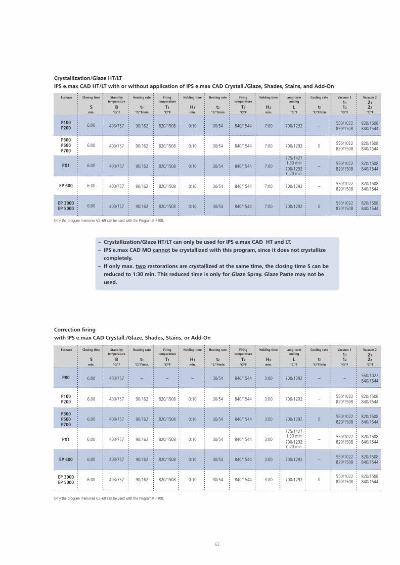
63
– Crystallization/Glaze HT/LT can only be used for IPS e.max CAD HT and LT.
– IPS e.max CAD MO cannot be crystallized with this program, since it does not crystallize
completely.
– If only max. two restorations are crystallized at the same time, the closing time S can be
reduced to 1:30 min. This reduced time is only for Glaze Spray. Glaze Paste may not be
used.
Furnace
P100P200
P300P500P700
PX1
EP 600
EP 3000EP 5000
Closing time
Smin.
6:00
6:00
6:00
6:00
6:00
Stand-bytemperature
B°C/°F
403/757
403/757
403/757
403/757
403/757
Heating rate
t1
°C/°F/min
90/162
90/162
90/162
90/162
90/162
Firingtemperature
T1
°C/°F
820/1508
820/1508
820/1508
820/1508
820/1508
Holding time
H1
min.
0:10
0:10
0:10
0:10
0:10
Heating rate
t2
°C/°F/min
30/54
30/54
30/54
30/54
30/54
Firingtemperature
T2
°C/°F
840/1544
840/1544
840/1544
840/1544
840/1544
Holding time
H2
min.
7:00
7:00
7:00
7:00
7:00
Long-termcooling
L°C/°F
700/1292
700/1292
775/14271:30 min700/12920:20 min
700/1292
700/1292
Cooling rate
tl
°C/°F/min
–
0
–
–
0
Vacuum 1
11
12
°C/°F
550/1022820/1508
550/1022820/1508
550/1022820/1508
550/1022820/1508
550/1022820/1508
Vacuum 2
21
22
°C/°F
820/1508840/1544
820/1508840/1544
820/1508840/1544
820/1508840/1544
820/1508840/1544
Crystallization/Glaze HT/LT
IPS e.max CAD HT/LT with or without application of IPS e.max CAD Crystall./Glaze, Shades, Stains, and Add-On
Correction firing
with IPS e.max CAD Crystall./Glaze, Shades, Stains, or Add-On
Only the program memories 65-69 can be used with the Programat P100.
Furnace
P80
P100P200
P300P500P700
PX1
EP 600
EP 3000EP 5000
Closing time
Smin.
6:00
6:00
6:00
6:00
6:00
6:00
Stand-bytemperature
B°C/°F
403/757
403/757
403/757
403/757
403/757
403/757
Heating rate
t1
°C/°F/min.
–
90/162
90/162
90/162
90/162
90/162
Firingtemperature
T1
°C/°F
–
820/1508
820/1508
820/1508
820/1508
820/1508
Holding time
H1
min.
–
0:10
0:10
0:10
0:10
0:10
Heating rate
t2
°C/°F/min
30/54
30/54
30/54
30/54
30/54
30/54
Firingtemperature
T2
°C/°F
840/1544
840/1544
840/1544
840/1544
840/1544
840/1544
Holding time
H2
min.
3:00
3:00
3:00
3:00
3:00
3:00
Long-termcooling
L°C/°F
700/1292
700/1292
700/1292
775/14271:30 min700/12920:20 min
700/1292
700/1292
Cooling rate
tl
°C/°F/min
–
–
0
–
–
0
Vacuum 1
11
12
°C/°F
–
550/1022820/1508
550/1022820/1508
550/1022820/1508
550/1022820/1508
550/1022820/1508
Vacuum 2
21
22
°C/°F
550/1022840/1544
820/1508840/1544
820/1508840/1544
820/1508840/1544
820/1508840/1544
820/1508840/1544
Only the program memories 65-69 can be used with the Programat P100.
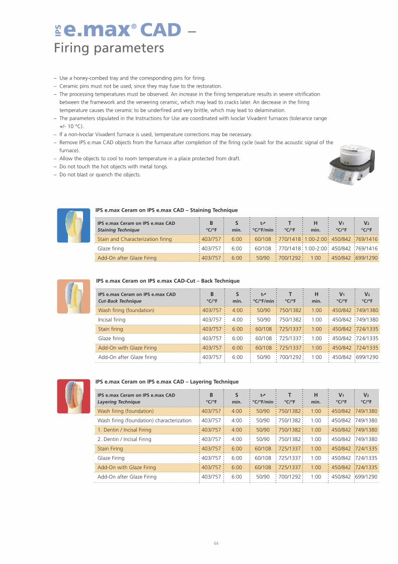
IPS e.max Ceram on IPS e.max CAD – Layering Technique
IPS e.max Ceram on IPS e.max CAD B S t� T H V1 V2
Layering Technique °C/°F min. °C/°F/min °C/°F min. °C/°F °C/°F
Wash firing (foundation) 403/757 4:00 50/90 750/1382 1:00 450/842 749/1380
Wash firing (foundation) characterization 403/757 4:00 50/90 750/1382 1:00 450/842 749/1380
1. Dentin / Incisal Firing 403/757 4:00 50/90 750/1382 1:00 450/842 749/1380
2. Dentin / Incisal Firing 403/757 4:00 50/90 750/1382 1:00 450/842 749/1380
Stain Firing 403/757 6:00 60/108 725/1337 1:00 450/842 724/1335
Glaze Firing 403/757 6:00 60/108 725/1337 1:00 450/842 724/1335
Add-On with Glaze Firing 403/757 6:00 60/108 725/1337 1:00 450/842 724/1335
Add-On after Glaze Firing 403/757 6:00 50/90 700/1292 1:00 450/842 699/1290
IPS e.max Ceram on IPS e.max CAD-Cut – Back Technique
IPS e.max Ceram on IPS e.max CAD B S t� T H V1 V2
Cut-Back Technique °C/°F min. °C/°F/min °C/°F min. °C/°F °C/°F
Wash firing (foundation) 403/757 4:00 50/90 750/1382 1:00 450/842 749/1380
Incisal firing 403/757 4:00 50/90 750/1382 1:00 450/842 749/1380
Stain firing 403/757 6:00 60/108 725/1337 1:00 450/842 724/1335
Glaze firing 403/757 6:00 60/108 725/1337 1:00 450/842 724/1335
Add-On with Glaze Firing 403/757 6:00 60/108 725/1337 1:00 450/842 724/1335
Add-On after Glaze firing 403/757 6:00 50/90 700/1292 1:00 450/842 699/1290
IPS e.max Ceram on IPS e.max CAD – Staining Technique
IPS e.max Ceram on IPS e.max CAD B S t� T H V1 V2
Staining Technique °C/°F min. °C/°F/min °C/°F min. °C/°F °C/°F
Stain and Characterization firing 403/757 6:00 60/108 770/1418 1:00-2:00 450/842 769/1416
Glaze firing 403/757 6:00 60/108 770/1418 1:00-2:00 450/842 769/1416
Add-On after Glaze Firing 403/757 6:00 50/90 700/1292 1:00 450/842 699/1290
64
e.max® CAD –Firing parameters
IPS
– Use a honey-combed tray and the corresponding pins for firing.
– Ceramic pins must not be used, since they may fuse to the restoration.
– The processing temperatures must be observed. An increase in the firing temperature results in severe vitrification
between the framework and the veneering ceramic, which may lead to cracks later. An decrease in the firing
temperature causes the ceramic to be underfired and very brittle, which may lead to delamination.
– The parameters stipulated in the Instructions for Use are coordinated with Ivoclar Vivadent furnaces (tolerance range
+/- 10 °C).
– If a non-Ivoclar Vivadent furnace is used, temperature corrections may be necessary.
– Remove IPS e.max CAD objects from the furnace after completion of the firing cycle (wait for the acoustic signal of the
furnace).
– Allow the objects to cool to room temperature in a place protected from draft.
– Do not touch the hot objects with metal tongs.
– Do not blast or quench the objects.

65
– The firing parameters listed represent standard values and apply to the Ivoclar Vivadent furnaces P200,
P300, P500, P700. For Ivoclar furnaces of an older generation, e.g. P20, P80, P90, P95, P100, PX1 and EP600
Combi, these temperatures are also valid as standard values. However, depending on the age of the heat-
ing muffle, the values may deviate by approximately ± 10 °C.
– If a non-Ivoclar Vivadent furnace is used, temperature corrections may be necessary.
– Regional differences in the power supply or the operation of several electronic devices by means of the
same circuit may render adjustments of the temperatures necessary.
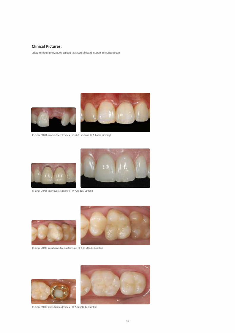
66
Clinical Pictures:Unless mentioned otherwise, the depicted cases were fabricated by Jürgen Seger, Liechtenstein.
IPS e.max CAD LT crown (cut-back technique) on a ZrO2 abutment (Dr A. Kurbad, Germany)
IPS e.max CAD LT crown (cut-back technique) (Dr A. Kurbad, Germany)
IPS e.max CAD HT partial crown (staining technique) (Dr A. Peschke, Liechtenstein)
IPS e.max CAD HT crown (staining technique) (Dr A. Peschke, Liechtenstein)

Ivoclar Vivadent AGBendererstrasse 29494 SchaanLiechtensteinTel. +423 235 35 35Fax +423 235 33 60www.ivoclarvivadent.com
Ivoclar Vivadent Pty. Ltd.1 – 5 Overseas DriveP.O. Box 367Noble Park, Vic. 3174AustraliaTel. +61 3,979,595 99Fax +61 3,979,596 45www.ivoclarvivadent.com.au
Ivoclar Vivadent GmbHBremschlstr. 16Postfach 2236706 BürsAustriaTel. +43 5552 624 49Fax +43 5552 675 15www.ivoclarvivadent.com
Ivoclar Vivadent do Brasil Ltda.Rua Geraldo Flausino Gomes,78 – 6.º andar Cjs. 61/62Bairro: Brooklin NovoCEP: 04575-060 São Paulo – SPBrazilTel. +55 11 3466 0800Fax +55 11 3466 0840www.ivoclarvivadent.com.br
Ivoclar Vivadent Inc.2785 Skymark Avenue, Unit 1MississaugaOntario L4W 4Y3CanadaTel. +1,905,238 5700Fax +1,905,238 5711www.ivoclarvivadent.us
Ivoclar Vivadent Marketing Ltd.Rm 603 Kuen YangInternational Business PlazaNo. 798 Zhao Jia Bang RoadShanghai 200030ChinaTel. +86 21 5456 0776Fax +86 21 6445 1561www.ivoclarvivadent.com
Ivoclar Vivadent Marketing Ltd.Calle 134 No. 7-B-83, Of. 520BogotáColombiaTel. +57 1,627 33 99Fax +57 1,633 16 63www.ivoclarvivadent.com
Ivoclar Vivadent SASB.P. 118F-74410 Saint-JoriozFranceTel. +33 450 88 64 00Fax +33,450 68 91 52www.ivoclarvivadent.fr
Ivoclar Vivadent GmbHDr. Adolf-Schneider-Str. 273479 Ellwangen, JagstGermanyTel.Fax +49 (0) 79 61 / 63 26www.ivoclarvivadent.de
Ivoclar Vivadent Marketing Ltd.(Liaison Office)503/504 Raheja Plaza15 B Shah Industrial EstateVeera Desai Road, Andheri( West)Mumbai, 400 053IndiaTel. +91 (22) 2673 0302Fax +91 (22) 2673 0301www.ivoclarvivadent.com
Ivoclar Vivadent s.r.l. & C. s.a.sVia Gustav Flora, 3239025 Naturno (BZ)ItalyTel. +39 0473 67 01 11Fax +39 0473 66 77 80www.ivoclarvivadent.it
Ivoclar Vivadent K.K.1-28-24-4F HongoBunkyo-kuTokyo 113-0033JapanTel. +81 3 6903 3535Fax +81 3 5844 3657www.ivoclarvivadent.jp
Ivoclar Vivadent S.A. de C.V.Av. Mazatlán No. 61, Piso 2Col. Condesa06170 México, D.F.MexicoTel. +52 (55) 5062-1000Fax +52 (55) 5062-1029www.ivoclarvivadent.com.mx
Ivoclar Vivadent Ltd.12 Omega St, AlbanyPO Box 5243 Wellesley StAuckland New ZealandTel. +64 9,914 9999Fax +64 9,814 9990www.ivoclarvivadent.co.nz
Ivoclar VivadentPolska Sp. z.o.o.ul. Jana Pawla II 78PL-00175 WarszawaPolandTel. +48 22,635 54 96Fax +48 22,635 54 69www.ivoclarvivadent.pl
Ivoclar Vivadent Marketing Ltd.Derbenevskaja Nabereshnaya 11, Geb.W115114 MoscowRussiaTel. +7,495,913 66 19Fax +7,495,913 66 15www.ivoclarvivadent.ru
Ivoclar Vivadent Marketing Ltd.171 Chin Swee Road#02-01 San CentreSingapore 169877Tel. +65 6535 6775Fax +65 6535 4991www.ivoclarvivadent.com
Ivoclar Vivadent S.L.U.c/ Emilio Muñoz Nº 15Entrada c/ AlbarracinE-28037 MadridSpainTel. + 34 91 375 78 20Fax + 34 91 375 78 38www.ivoclarvivadent.es
Ivoclar Vivadent ABDalvägen 14S-169 56 SolnaSwedenTel. +46 (0) 8,51493,930Fax +46 (0) 8,51493,940www.ivoclarvivadent.se
Ivoclar Vivadent Liaison OfficeAhi Evran Caddesi No 1Polaris Is Merkezi Kat: 780670 MaslakIstanbulTurkeyTel. +90 212 346 04 04Fax +90 212 346 04 24www.ivoclarvivadent.com
Ivoclar Vivadent LimitedGround Floor Compass BuildingFeldspar CloseWarrens Business ParkEnderbyLeicester LE19 4SEUnited KingdomTel. +44,116,284 78 80Fax +44,116,284 78 81www.ivoclarvivadent.com
Ivoclar Vivadent, Inc.175 Pineview DriveAmherst, N.Y. 14228USATel.Fax +1 716 691 2285www.ivoclarvivadent.us
Ivoclar Vivadent – worldwide
Date information prepared: 06/2009
These materials have been developed solely for use in dentistry. Processing should be carried out strictlyaccording to the Instructions for Use. Liability cannot be accepted for damages resulting from failure toobserve the Instructions or the stipulated area of application. The user is responsible for testing the productsfor their suitability and use for any purpose not explicitly stated in the Instructions. Descriptions and dataconstitute no warranty of attributes and are not binding. These regulations also apply if the materials are usedin conjunction with products of other manufacturers.
Printed in Liechtenstein© Ivoclar Vivadent AG, Schaan / Liechtenstein627893/0510/e/BVD


