A visual cryptography scheme (VCS) is a kind of secret sharing scheme which allows the encoding of a secret image into shares distributed to participants. The beauty of such a scheme is that a set of qualified participants is able to recover the secret image without any cryptographic knowledge and computation devices. An extended visual cryptography scheme (EVCS) is a kind of VCS which consists of meaningful shares (compared to the random shares of traditional VCS). In this paper, we propose a construction of EVCS which is realized by embedding random shares into meaningful covering shares, and we call it the embedded EVCS. Experimental results compare some of the well-known EVCSs proposed in recent years systematically, and show that the proposed embedded EVCS has competitive visual quality compared with many of the well-known EVCSs in the literature. In addition, it has many specific advantages against these well-known EVCSs, respectively.
EMBEDDED EXTENDED VISUAL CRYPTOGRAPHY SCHEMES By A PROJECT REPORT Submitted to the Department of Computer Science & Engineering in the FACULTY OF ENGINEERING & TECHNOLOGY In partial fulfillment of the requirements for the award of the degree Of MASTER OF TECHNOLOGY IN COMPUTER SCIENCE & ENGINEERING APRIL 2012
Transcript
EMBEDDED EXTENDED VISUAL CRYPTOGRAPHY SCHEMES
By
A
PROJECT REPORT
Submitted to the Department of Computer Science & Engineering in the
FACULTY OF ENGINEERING & TECHNOLOGY
In partial fulfillment of the requirements for the award of the degree
Of
MASTER OF TECHNOLOGY
IN
COMPUTER SCIENCE & ENGINEERING
APRIL 2012
BONAFIDE CERTIFICATE
Certified that this project report titled “Embedded Extended Visual Cryptography
Schemes” is the bonafide work of Mr. _____________Who carried out the research
under my supervision Certified further, that to the best of my knowledge the work
reported herein does not form part of any other project report or dissertation on the basis
of which a degree or award was conferred on an earlier occasion on this or any other
candidate.
Signature of the Guide Signature of
the H.O.D
Name Name
CHAPTER 01
ABSTRACT:
A visual cryptography scheme (VCS) is a kind of secret sharing scheme which allows the
encoding of a secret image into shares distributed to participants. The beauty of such a
scheme is that a set of qualified participants is able to recover the secret image without
any cryptographic knowledge and computation devices. An extended visual cryptography
scheme (EVCS) is a kind of VCS which consists of meaningful shares (compared to the
random shares of traditional VCS). In this paper, we propose a construction of EVCS
which is realized by embedding random shares into meaningful covering shares, and we
call it the embedded EVCS. Experimental results compare some of the well-known
EVCSs proposed in recent years systematically, and show that the proposed embedded
EVCS has competitive visual quality compared with many of the well-known EVCSs in
the literature. In addition, it has many specific advantages against these well-known
EVCSs, respectively.
PROJECT URPOSE:
Purpose of a VCS with random shares the traditional VCS or simply the VCS. In general,
a traditional VCS takes a secret image as input, and outputs shares that satisfy two condi-
tions: 1) any qualified subset of shares can recover the secret image; 2) any forbidden
subset of shares cannot obtain any information of the secret image other than the size of
the secret image.
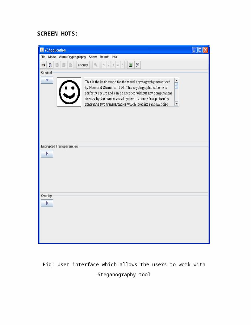
PROJECT SCOPE:
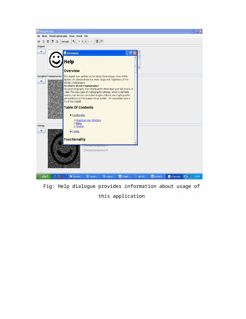
System provides a friendly environment to deal with images. Generally tools supports
only one kind of image formats. Our application supports .gif and .png (portable net-
work graphics) formatted images and our application has been developed using swing
and applet technologies, hence provides a friendly environment to users.
VCS of an EVCS, we mean a traditional VCS that have the same access structure with
the EVCS. Generally, an EVCS takes a secret image and original share images as inputs,
and outputs shares that satisfy the following three option:
1) any qualified subset of shares can recover the secret image;
2) any forbidden subset of shares cannot obtain any information of the secret image other
than the size of the secret image;
3) all the shares are meaningful images.
PRODUCT FEATURES:
EVCS is flexible in the sense that there exist two trade-offs between the share pixel ex-
pansion and the visual quality of the shares and between the secret image pixel expansion
and the visual quality of the shares. This flexibility allows the dealer to choose the proper
parameters for different applications. Comparisons on the experimental results show that
the visual quality of the share of the proposed embedded EVCS is competitive
with that of many of the well-known EVCSs in the literature.
INTRODUCTION:
THE basic principle of the visual cryptography scheme (VCS) was first introduced by
Naor and Shamir. VCS is a kind of secret sharing scheme that focuses on sharing secret
images. The idea of the visual cryptography model proposed in is to split a secret image
into two random shares (printed on transparencies) which separately reveals no informa-
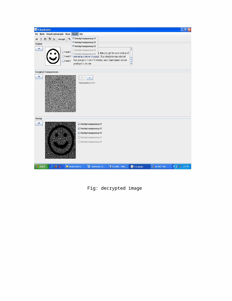
tion about the secret image other than the size of the secret image. The secret image can
be reconstructed by stacking the two shares. The underlying operation of this scheme is
logical operation OR.
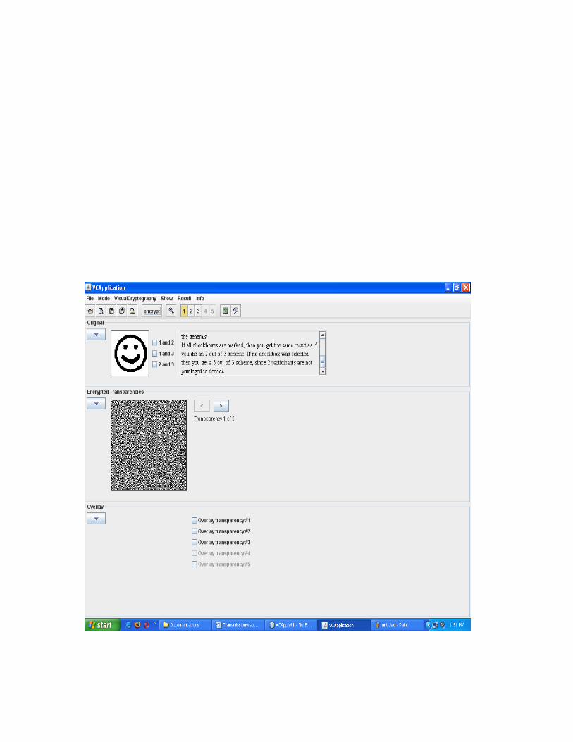
In this paper, we call a VCS with random shares the traditional VCS or simply the VCS.
In general, a traditional VCS takes a secret image as input, and outputs shares that satisfy
two conditions: 1) any qualified subset of shares can recover the secret image; 2) any for-
bidden subset of shares cannot obtain any information of the secret image other than the
size of the secret image. An example of traditional (2,2)-VCS can be found in Fig. 1,
where, generally speaking, a –VCS means any out of shares could recover the secret im-
age. In the scheme of Fig. 1, shares (a) and (b) are distributed to two participants secretly,
and each participant cannot get any information about the secret image, but after
stacking shares (a) and (b), the secret image can be observed visually by the participants.
VCS has many special applications, for example, transmitting military orders to soldiers
who may have no cryptographic knowledge or computation devices in the battle field.
Many other applications of VCS, other than its original objective (i.e., sharing secret im-
age), have been found, for example, authentication and identification, watermarking
and transmitting passwords etc.
The associated secret sharing problem and its physical properties such as contrast, pixel
expansion, and color were extensively studied by researchers worldwide. For example,
showed constructions of threshold VCS with perfect reconstruction of the black pixels.
Furthermore, Eisen et al. proposed a construction of threshold VCS for specified white-
ness levels of the recovered pixels. The term of extended visual cryptography scheme
(EVCS) was first introduced by Naor et al. in, where a simple example of (2,2)-EVCS
was presented. In this paper, when we refer to a corresponding VCS of an EVCS, we
mean a traditional VCS that have the same access structure with the EVCS.
Generally, an EVCS takes a secret image and original share images as inputs, and outputs
shares that satisfy the following three conditions: 1) any qualified subset of shares can re-
cover the secret image; 2) any forbidden subset of shares cannot obtain any information
of the secret image other than the size of the secret image; 3) all the shares are meaning-
ful images. Examples of EVCS can be found in the experimental results of this
paper, such as Figs. 2–9. EVCS can also be treated as a technique of steganography. One
scenario of the applications of EVCS is to avoid the custom inspections, because the
shares of EVCS are meaningful images, hence there are fewer chances for the shares to
be suspected and detected.
CHAPTER 02
SYSTEM ANALYSIS:
PROBLEM DEFINITION:
Whenever we transmit the data (image) in the network, any unauthenticated person can
read our data (image). In order to provide security to data (image) generally sender will
encrypt the data (image) and send it the intended person and the receiver will decrypt the
encrypted data(image) and uses it.
EXISTING SYSTEM:
Visual cryptography is the art and science of encrypting the image in such a way that
no-one apart from the sender and intended recipient even realizes the original image, a
form of security through obscurity. By contrast, cryptography obscures the original im-
age, but it does not conceal the fact that it is not the actual image.
LIMITATIONS OF EXISTING SYSTEM:
The existing system does not provide a friendly environment to encrypt or decrypt the
data (images).
PROPOSED SYSTEM:
Proposed system Visual cryptography provides a friendly environment to deal with im-
ages. Generally cryptography tools supports only one kind of image formats. Our applica-
tion supports .gif and .png (portable network graphics) formatted images and our applica-
tion has been developed using swing and applet technologies, hence provides a friendly
environment to users.
ADVANTAGES OF PROPOSED SYSTEM:
EVCS is flexible in the sense that there exist two trade-offs between the share pixel ex-
pansion and the visual quality of the shares and between the secret image pixel expansion
and the visual quality of the shares. This flexibility allows the dealer to choose the proper
parameters for different applications. Comparisons on the experimental results show that
the visual quality of the share of the proposed embedded EVCS is competitive
with that of many of the well-known EVCSs in the literature.
PROCESS FLOW DIAGRAMS FOR EXISTING AND PROPOSED
SYSTEM:
FEASIBILITY STUDY:
The feasibility of the project is analyzed in this phase and business proposal is put forth
with a very general plan for the project and some cost estimates. During system analysis
the feasibility study of the proposed system is to be carried out. This is to ensure that the
proposed system is not a burden to the company. For feasibility analysis, some
understanding of the major requirements for the system is essential.
Three key considerations involved in the feasibility analysis are
ECONOMICAL FEASIBILITY
TECHNICAL FEASIBILITY
SOCIAL FEASIBILITY
ECONOMICAL FEASIBILITY
This study is carried out to check the economic impact that the system will have
on the organization. The amount of fund that the company can pour into the research and
development of the system is limited. The expenditures must be justified. Thus the
developed system as well within the budget and this was achieved because most of the
technologies used are freely available. Only the customized products had to be purchased.
TECHNICAL FEASIBILITY
This study is carried out to check the technical feasibility, that is, the
technical requirements of the system. Any system developed must not have a high
demand on the available technical resources. This will lead to high demands on the
available technical resources. This will lead to high demands being placed on the client.
The developed system must have a modest requirement, as only minimal or null changes
are required for implementing this system.
SOCIAL FEASIBILITY
The aspect of study is to check the level of acceptance of the system by the user.
This includes the process of training the user to use the system efficiently. The user must
not feel threatened by the system, instead must accept it as a necessity. The level of
acceptance by the users solely depends on the methods that are employed to educate the
user about the system and to make him familiar with it. His level of confidence must be
raised so that he is also able to make some constructive criticism, which is welcomed, as
he is the final user of the system.
HARDWARE AND SOFTWARE REQUIREMENTS:
HARDWARE REQUIREMENTS:
• System : Pentium IV 2.4 GHz.
• Hard Disk : 40 GB.
• Floppy Drive : 1.44 Mb.
• Monitor : 15 VGA Colour.
• Mouse : Logitech.
• Ram : 512 Mb.
SOFTWARE REQUIREMENTS:
• Operating system : Windows XP.
• Coding Language : JDK 1.6
• Tools : Netbeans
FUNCTIONAL REQUIREMENTS:
Functional requirements specify which output file should be produced from the given
file they describe the relationship between the input and output of the system, for each
functional requirement a detailed description of all data inputs and their source and the
range of valid inputs must be specified.
NON FUNCTIONAL REQUIREMENTS:
Describe user-visible aspects of the system that are not directly related with the
functional behavior of the system. Non-Functional requirements include quantitative
constraints, such as response time (i.e. how fast the system reacts to user commands.) or
accuracy ((.e. how precise are the systems numerical answers.)
PSEUDO REQUIREMENTS:
The client that restricts the implementation of the system imposes these requirements.
Typical pseudo requirements are the implementation language and the platform on
which the system is to be implemented. These have usually no direct effect on the users
view of the system.
LITERATURE SURVEY:
Literature survey is the most important step in software development process. Before
developing the tool it is necessary to determine the time factor, economy n company
strength. Once these things r satisfied, ten next step is to determine which operating
system and language can be used for developing the tool. Once the programmers start
building the tool the programmers need lot of external support. This support can be
obtained from senior programmers, from book or from websites. Before building the
system the above consideration r taken into account for developing the proposed system.
The associated secret sharing problem and its physical properties such as contrast, pixel
expansion, and color were extensively studied by researchers worldwide. For example,
Naor et al and Blundo et al. showed constructions of threshold VCS with perfect
reconstruction of the black pixels. Ateniese et al. gave constructions of VCS for the
general access structure. Krishna et al., Luo et al., Hou et al., and Liu et al. considered
color VCSs.Shyu et al. proposed a scheme which can share multiple secret images [13].
Furthermore, Eisen et al. proposed a construction of threshold VCS for specified
whiteness levels of the recovered pixels.
The term of extended visual cryptography scheme (EVCS) was first introduced by Naor
et al. in, where a simple example of (2,2)-EVCS was presented. In this paper, when we
refer to a corresponding VCS of an EVCS, we mean a traditional VCS that have the same
access structure with the EVCS. Generally, an EVCS takes a secret image and original
share images as inputs, and outputs shares that satisfy the following three conditions: 1)
any qualified subset of shares can recover the secret image; 2) any forbidden subset of
shares cannot obtain any information of the secret image other than the size of the secret
image; 3) all the shares are meaningful images.
EVCS can also be treated as a technique of steganography. One scenario of the
applications of EVCS is to avoid the custom inspections, because the shares of EVCS are
meaningful images, hence there are fewer chances for the shares to be suspected and
detected.
There have been many EVCSs proposed in the literature. Furthermore, Zhou et al. [20]
presented an EVCS by using halftoning techniques, and hence can treat gray-scale input
share images. Theirmethodsmade use of the complementary images to cover the visual
information of the share images. Recently, Wang et al. proposed three EVCSs by using
an error diffusion halftoning technique to obtain nice looking shares. Their first EVCS
also made use of complementary shares to cover the visual information of the shares as
the way proposed in. Their second EVCS imported auxiliary black pixels to cover the
visual information of the shares. In such a way, each qualified participants did not
necessarily require a pair of complementary share images. Their third EVCS modified the
halftoned share images and imported extra black pixels to cover the visual information of
the shares.
1) Visual Cryptography for General Access Structure by Multi-pixel Encoding with


![Embedded Linux Conference, San Diego, 2016 Cryptography … · 2016-07-06 · Misuse of cryptography is common source of vulnerabilities “41 of the 100 apps selected [...] were](https://static.documents.pub/doc/80x56/5f8cd0f45877b84f0a683092/embedded-linux-conference-san-diego-2016-cryptography-2016-07-06-misuse-of-cryptography.jpg)


![Visual Cryptography Schemes: A Comprehensive Survey · Visual cryptography was first invented by Moni Naor and Adi Shamir in 1995 at [1]. They produced a basic scheme They produced](https://static.documents.pub/doc/80x56/5dd10dcdd6be591ccb63fee4/visual-cryptography-schemes-a-comprehensive-survey-visual-cryptography-was-first.jpg)


