1 EMBEDDED PROGRAMMING LABORATORY LAB MANUAL Course Code : BESB09 Regulations : IARE - R18 Class : I Semester Branch : M.TECH(ES) Prepared By Ms. M. SUGUNA SRI Assistant Professor, ECE Department of Electronics & Communication Engineering INSTITUTE OF AERONAUTICAL ENGINEERING (Autonomous) Dundigal – 500 043, Hyderabad
Transcript
1
EMBEDDED PROGRAMMING LABORATORY
LAB MANUAL
Course Code : BESB09
Regulations : IARE - R18
Class : I Semester
Branch : M.TECH(ES)
Prepared By
Ms. M. SUGUNA SRI
Assistant Professor, ECE
Department of Electronics & Communication Engineering
INSTITUTE OF AERONAUTICAL ENGINEERING (Autonomous)
Dundigal – 500 043, Hyderabad
2
INDEX
S. No Name of the Content PAGE NO.
1 Lab Objective 3
2 Introduction About Lab 4
3 LAB CODE 5
4 List of Lab Exercises 6
5 Description about ES Concepts 7
6 Programs List 13
7 References 82
3
Lab Objective:
An embedded system is some combination of computer hardware and software, either fixed in
capability or programmable, that is specifically designed for a particular kind of application device.
Industrial machines, automobiles, medical equipment, cameras, household appliances, airplanes, vending
machines, and toys (as well as the more obvious cellular phone and PDA) are among the myriad possible
hosts of an embedded system. Embedded systems that are programmable are provided with a
programming interface, and embedded systems programming is a specialized occupation.
An embedded system is a special-purpose computer system designed to perform one or a few
dedicated functions, often with real-time computing constraints. It is usually embedded as part of a
complete device including hardware and mechanical parts. In contrast, a general-purpose computer, such
as a personal computer, can do many different tasks depending on programming. Embedded systems have
become very important today as they control many of the common devices we use.
Since the embedded system is dedicated to specific tasks, design engineers can optimize it, reducing the
size and cost of the product, or increasing the reliability and performance. Some embedded systems are
mass-produced, benefiting from economies of scale.
4
INTRODUCTION ABOUT LAB
There are 30 systems (Dell) installed in this Lab. Their configurations are as follows:
Processor : Intel(R) core (TM) - i3 -4150
CPU RAM : 4 GB
Hard Disk : 500 GB
Mouse : Optical Mouse
Network Interface card : Present
Software
1 All systems are configured in DUAL BOOT mode i.e, Students can boot from Windows 07.This
is very useful for students because they are familiar with different Operating Systems so that they can
execute their programs in different programming environments.
2 Each student has a separate login for database access
3 Software installed: Keil Micro vision, OFFICE-07, Systems are provided for students in the1:1
ratio.
4 Systems are assigned numbers and same system is allotted for students when they do the lab.
5
LAB CODE
1. Students should report to the concerned labs as per time table schedule.
2. Students who turn up late to the labs will in no case be permitted to do the program scheduled for the day.
3. After completion of the program, certification of the concerned staff in-charge in the observation book is necessary.
4. Students should bring a notebook of about 100 pages and should enter the reading/observations into
5. the notebook while performing the experiment.
6. The record of observations along with the detailed experimental procedure of the experiment performed in the immediate last session should be submitted and certified by the staff member in-charge.
7. Not more than three students in a group are permitted to perform the experiment on a setup.
8. The group-wise division made in the beginning should be adhered to and no mix up student among different groups will be permitted later.
9. The components required pertaining to the experiment should be collected from stores in-charge after duly filling in the requisition form.
10. When the experiment is completed, students should disconnect the setup made by them, and should
return all the components/instruments taken for the purpose.
11. Any damage of the equipment or burn-out of components will be viewed seriously either by putting
penalty or by dismissing the total group of students from the lab for the semester/year.
12. Students should be present in the labs for the total scheduled duration.
13. Students are required to prepare thoroughly to perform the experiment before coming to Laboratory.
14. Procedure sheets/data sheets provided to the student‘s groups should be maintained neatly and to be
returned after the experiment.
6
List of Lab Excercises
EMBEDDED PROGRAMMING LABORATORY – Lab Programs List
Submission – 1
Week – 1 Program to toggle all the bits of port P1 continuously with 250 ms delay.
Week – 2 Program to interface a switch and a buzzer to two different pins of a port such that the buzzer
should sound as long as the switch is pressed.
Week – 3 Program to interface LCD data pins to port P1 and display a message on it
Week – 4 Program to interface seven segment display using 89V51RD2
Week – 5 Program to interface keypad. Whenever a key is pressed, it should be displayed on LCD
Week – 6 Program to transmit message from microcontroller to PC serially using RS232
Program to receive a message from PC to microcontroller serially using RS232
Week – 7 Program to interface Stepper Motor to rotate the motor in clockwise and anticlockwise
Directions
Week – 8 Program to read data from temperature sensor and display the temperature value
Week – 9 Port RTOS on to 89V51 Microcontroller and verify. Run 2 to 3 tasks
simultaneously on 89V51 SDK. Use LCD interface, LED interface,
Serial communication.
Week – 10 Program to convert analog signal into digital (ADC).
Week – 11 Program to convert Digital into Analog (DAC).
Week – 12 Program to interface Elevator.
7
Description about ES Concepts:
Embedded systems are designed to do some specific task, rather than be a general-purpose computer for
multiple tasks. Some also have real-time performance constraints that must be met, for reason such as
safety and usability; others may have low or no performance requirements, allowing the system hardware
to be simplified to reduce costs. Embedded systems are not always separate devices. Most often they are
physically built-in to the devices they control.
The software written for embedded systems is often called firmware, and is stored in read-only memory
or Flash memory chips rather than a disk drive. It often runs with limited computer hardware resources:
small or no keyboard, screen, and little memory. Embedded systems range from no user interface at all
— dedicated only to one task — to full user interfaces similar to desktop operating systems in devices
such as PDAs. Simple embedded devices use buttons, LEDs, and small character- or digit-only displays,
often with a simple menu system.
Embedded Systems components:
8
Introduction to 8051 Microcontroller:
Microcontroller is a device which integrates number of components of a microprocessor system onto a
single chip. It typically includes:-
CPU (Central Processing unit)
RAM & ROM
I/O inputs & outputs – Serial & Parallel
Timers
Interrupt Controller
By including the features that are specific to the task (Control), Cost is relatively low.
Microcontroller are a ―one chip solutions‖ which drastically reduces parts count and design costs.
Block Diagram:
8051 Basic Components:
4K bytes internal ROM
128 bytes internal RAM
Four 8-bit I/O ports (P0 - P3).
Two 16-bit timers/counters
One serial interface
9
8051 features:
4K bytes ROM
128 bytes RAM
Four 8-bit I/O ports
Two 16-bit timers
Serial interface
64K external code memory space
ALU
Working Registers
Clock Circuits
Timers and Counters
Serial Data Communication.
8051 CPU Registers:
A (8-bit Accumulator)
B (8-bit register for Mul &Div)
PSW (8-bit Program Status Word)
SP (8-bit Stack Pointer)
PC (16-bit Program Counter)
DPTR (16-bit Data Pointer)
Pin Description of the 8051:
The 8051 is a 40 pin device, but out of these 40 pins, 32 are used for I/O
24 of these are dual purpose, i.e. they can operate as I/O or a control line or as part of address or date
bus.
10
On board Peripherals:
8051 Development Board
(P89V51RD2)
1) hex-key pad 2) seven segment display
3) serial peripheral interface (spi) 4) led‘ display
5) analog to digital converter 6) lm35 temperature sensor
7) digital to analog converter 8) rtc battery
9) eeprom (i2c) 10) rtc
11) lcd display 12) gnd and vcc
13) lcd contrast (potentiometer) 14) p89v51rd2
15) crystal oscillator 16) max232
17) serial port connector 18) stepper motor driver
19) buzzer 20) reset button
21) push button switches 22) slide switches
23) ps/2 connector 24) relay output connector
25) power supply slide switch 26) power jack
27) 7805 voltage regulator 28) bridge rectifier
29) relay
Overview:
The UTS-MC-KIT-M7.3 has got P89V51RD2 microcontroller which has got 64KiloBytes of on
chip Flash memory and 1 KiloBytes of RAM. The kit is has got on board 11.0592MHz crystal for
generating the on chip clock of 11.0592MHz.
A Key feature of the board is it has got so many interfaces, with different on board peripherals
and has got expansion capability to add any further sensor and peripherals in future. This prototype board
is very easy to use for 8051 architecture. This board is interfaced with LED‘s, 7 SEG display, LCD
display, Pushbutton. This Board can also be interfaced with PC via serial communication and can be
viewed through hyper terminal. The LCD display can be connected easily through connectors. No
soldering work /No lose contact/ just plug in the berg connectors.
The board has got on chip peripherals like on board 32 KB bytes of RAM, Eight Light Emitting
Diodes, four Push Buttons, Four Seven Segment Displays, 16X2 Liquid Crystal Character Display(LCD),
Analog to Digital Converter, LM35 Temperature sensor, SPI based ADC, Hex Keypad, Buzzer relay,
steeper motor driver interface, Real time clock, RS-232 serial interface.
11
Component Description:
Microcontroller
The P89V51RD2 device contains a non-volatile 64KB Flash program memory.
In-System Programming (ISP) allows the user to download new code while the microcontroller sits in the application. A default serial loader (boot loader) program in ROM allows serial In-System
programming of the Flash memory via the UART without
the need for a loader in the Flash code.
This device executes one machine cycle in 6 clock cycles, hence providing twice the speed of a
conventional 80C51. An OTP configuration bit lets the user select conventional 12 clock timing if desired.
This device is a Single-Chip 8-Bit Micro controller manufactured in advanced CMOS process and is a
derivative of the 80C51 micro controller family. The instruction set is 100% compatible with the 80C51
instruction set.
The device also has four 8-bit I/O ports, three 16-bit timer/event counters, a multisource, and four-
priority-level, nested interrupt structure, an enhanced UART and on-chip oscillator and timing circuits.
The added features of the P89V51RD2 makes it a powerful micro controller for applications that require
pulse width modulation, high-speed I/O and up/down counting capabilities such as motor control.
Experimental Procedure for Keil4 IDE
(For all the experiments this procedure is same)
The RVision IDE is, for most developers, the easiest way to create embedded system programs.
This chapter describes commonly used RVision features and explains how to use them.
RVision is a Windows application that encapsulates the Keil microcontroller development tools
as well as several third-party utilities. RVision provides everything you need to start creating embedded
programs quickly. RVision includes an advanced editor, project manager, and make utility, which work
together to ease your development efforts, decreases the learning curve, and helps you to get started with
creating embedded applications quickly.
There are several tasks involved in creating a new embedded project:
Creating a Project File
Using the Project Windows
Creating Source Files
Adding Source Files to the Project
Using Targets, Groups, and Files
Setting Target Options, Groups Options, and File Options
Configuring the Startup Code
Building the Project
Creating a HEX File
The below section provides a step-by-step tutorial that shows you how to create an embedded project
using the RVision IDE.
12
Downloading the hex file to the target using Flash magic Software:
Open the Flash Magic tool for downloading into the Microcontroller Board. Click on Device menu select
option you will be popped up with a window named choose device. Under choose device options select
8051 and click on Ok button to open flash magic tool to download the hex file in to the MC
Terminal Software for Check the Serial port Data receiving from Microcontroller to PC:
Terminal is a simple serial port (COM) terminal emulation program. It can be used for communication
with different devices such as modems, routers, embedded microcontroller systems, GSM phones, GPS
modules... It is very useful debugging tool for serial communication applications.
13
14
- 22 -
EXPERIMENT – 1
Aim:
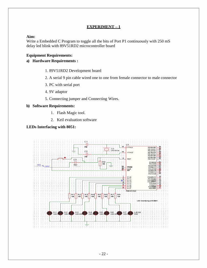
Write a Embedded C Program to toggle all the bits of Port P1 continuously with 250 mS
delay led blink with 89V51RD2 microcontroller board
Equipment Requirements:
a) Hardware Requirements :
1. 89V51RD2 Development board
2. A serial 9 pin cable wired one to one from female connector to male connector
3. PC with serial port
4. 9V adaptor
5. Connecting jumper and Connecting Wires.
b) Software Requirements:
1. Flash Magic tool.
2. Keil evaluation software
LEDs Interfacing with 8051:
- 23 -
Source code:
/* Program to toggle all the bits of Port P1 continuously with 250 mS delay. */
#include<REG51.H>
#define LEDPORT P1
void delay(unsigned int); void
main(void)
{
LEDPORT =0x00;
while(1)
{
LEDPORT = 0X00;
delay(250); LEDPORT = 0x11;
delay(250);
}
}
void delay(unsigned int itime)
{
unsigned int i,j;
for(i=0;i<itime;i++)
{
for(j=0;j<250;j++);
}
}
Flow Chart:
- 24 -
Hardware configuration:
Connect an 8 pin bus from Port 1 (P1) to the LED pins (No 3 pin strip) or place an 8 pin
Jumper connecting No2 and No3 pin strips.
Turn Off and On the Board or just reset it to view the output.
Results/Output verification:
Now the led program is running on Microcontroller. And the output can be seen in the
board. You can see led toggling
- 25 -
- 26 -
EXPERIMENT – 2
Aim:
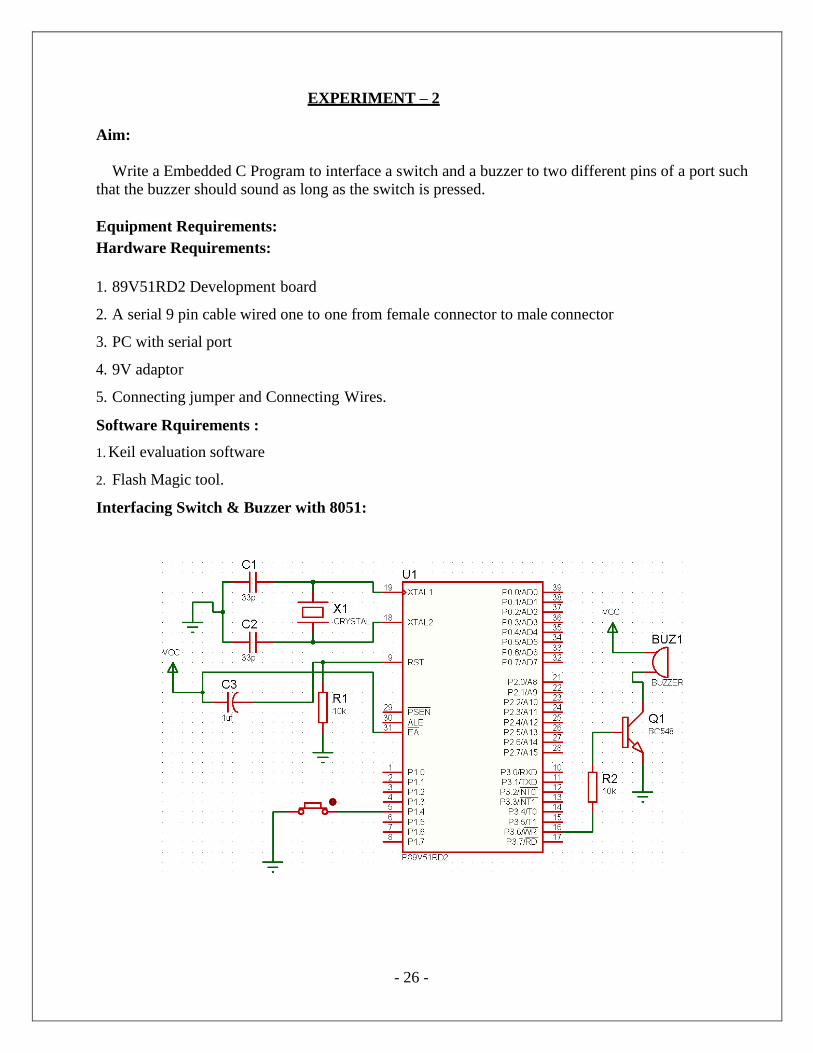
Write a Embedded C Program to interface a switch and a buzzer to two different pins of a port such
that the buzzer should sound as long as the switch is pressed.
Equipment Requirements:
Hardware Requirements:
1. 89V51RD2 Development board
2. A serial 9 pin cable wired one to one from female connector to male connector
3. PC with serial port
4. 9V adaptor
5. Connecting jumper and Connecting Wires.
Software Rquirements :
1. Keil evaluation software
2. Flash Magic tool.
Interfacing Switch & Buzzer with 8051:
- 27 -
Source code:
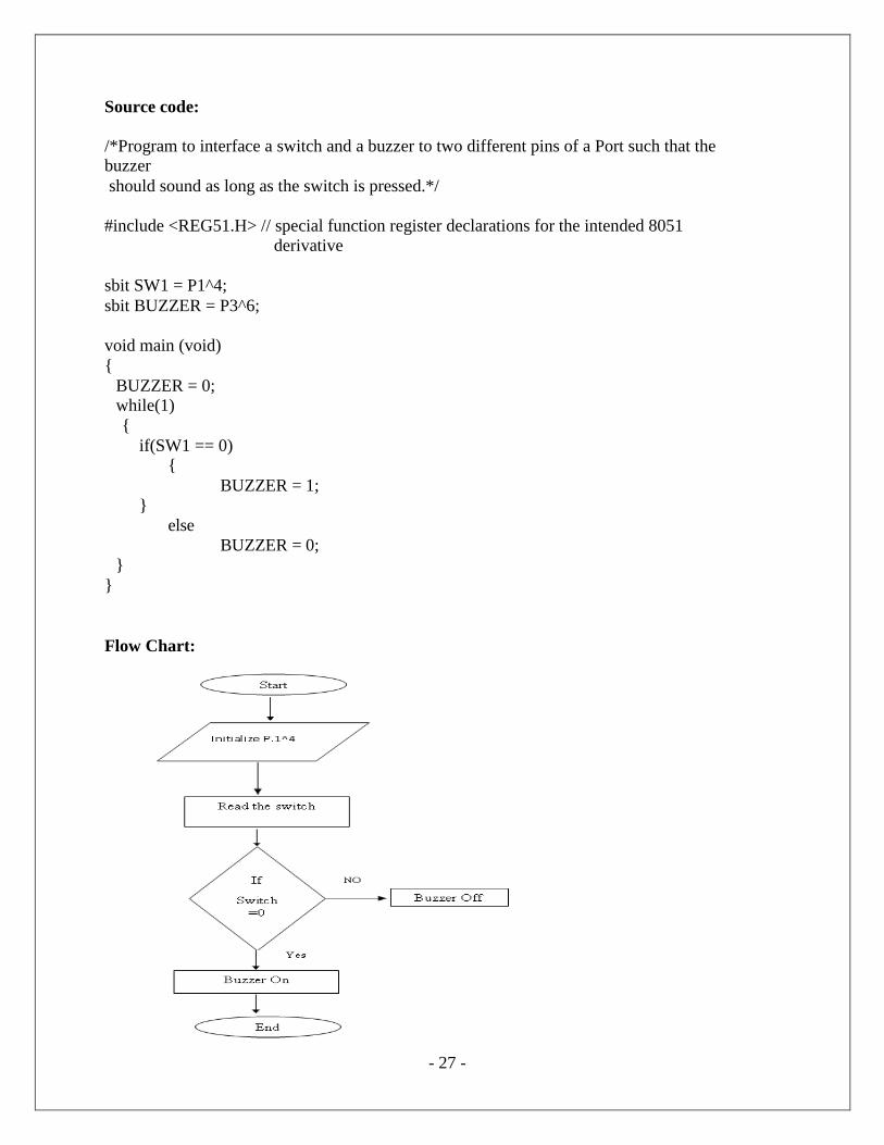
/*Program to interface a switch and a buzzer to two different pins of a Port such that the buzzer
should sound as long as the switch is pressed.*/
#include <REG51.H> // special function register declarations for the intended 8051
derivative
sbit SW1 = P1^4;
sbit BUZZER = P3^6;
void main (void)
{
BUZZER = 0; while(1)
{
if(SW1 == 0) {
}
else
}
}
BUZZER = 1;
BUZZER = 0;
Flow Chart:
- 28 -
Hardware configuration:
1. Connect a single pin wire from PORT 1.4 to any switch available on board.
2. Place the jumper at jp6 jumper position to connect the buzzer onboard to the controller.
3. Turn ON and OFF or reset the board, to view the output.
Results/Output verification:
After programming the code into the microcontroller just reset the microcontroller. You can
listen to the buzzer buzzing.
- 29 -
EXPERIMENT – 3
Aim:
Write a Embedded C Program to interface LCD data pins to port P1 and display a message
on it using 89V51RD2
Equipment Requirements:
Hardware Requirements :
1. 89V51RD2 Development board
2. A serial 9 pin cable wired one to one from female connector to male connector
3. PC with serial port
4. 9V adaptor
5. Connecting jumper and Connecting Wires.
Software Requirements :
1. Keil evaluation software
2. Flash Magic tool.
Interfacing 16*2 LCD with 8051:
- 30 -
Source code:
/*Program to interface LCD data pins to port P1 and display a message on it.*/
#include <reg51.h>
#include "lcd.h" // refer LCD.H code for more to about LCD
void Delay_sec(unsigned char s);
main( )
{
LCD_init();
while(1)
{ LCD_clear();
Delay_sec(1);
LCD_row1();
LCD_puts(" welcome come to embedded lab ");
LCD_row2();
LCD_puts(" iare ");
Delay_sec(5);
LCD_clear();
Delay_sec(1);
LCD_clear();
LCD_row1();
LCD_puts("EMEBEDDED SYSTEMS ");
LCD_row2();
LCD_puts("AERONAUTICAL ENGG.");
Delay_sec(5); }
}
void Delay_sec(unsigned char s)
{
unsigned char n;
for (n=0; n<s; n++)
{ LCD_delay(250);
LCD_delay(250);
}
}
- 31 -
Hardware configuration and Realization:
1. Connect a 6 pin jumper or 6 pin bus from PORT 2 to LCD module available on board.
2. Turn ON and OFF or reset the board, to view the output.
Results/Output verification:
After programming the code into the microcontroller just reset the microcontroller. You can see the
text on the LCD.
- 32 -
EXPERIMENT – 4
Aim:
Write a Embedded C Program to interface seven segment display using 89V51RD2
Equipment Requirements:
Hardware Requirements:
1. 89V51RD2 Development board
2. A serial 9 pin cable wired one to one from female connector to male connector
3. PC with serial port
4. 9V adaptor
5. Connecting jumper and Connecting Wires.
Software Requirements :
1. Keil evaluation software
2. Flash Magic tool.
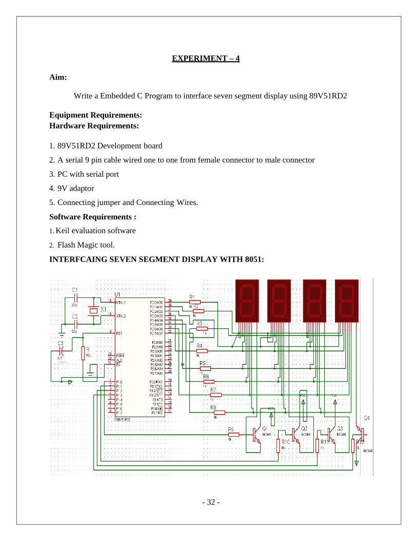
INTERFCAING SEVEN SEGMENT DISPLAY WITH 8051:
- 33 -
Source code:
/*Program to interface seven segment display unit.*/ #include <REG51.H>
#include <stdio.h>
#define LEDPORT P0
sbit CTRL0 = P1^0;
sbit CTRL1 = P1^1;
sbit CTRL2 = P1^2;
sbit CTRL3 = P1^3;
#define ZERO 0x02
#define ONE 0x9E
#define TWO 0x24
#define THREE 0x0C
#define FOUR 0x98
#define FIVE 0x48
#define SIX 0x40
#define SEVEN 0x1E
#define EIGHT 0x00 #define NINE 0x18
#define TEN 0x10
#define ELEVEN 0xC0
#define TWELVE 0x62
#define THIRTEEN 0x84
#define FOURTEEN 0x60
#define FIFTEEN 0x70
void Delay(void);
void main (void)
{
CTRL0 = 1; CTRL1 = 1;
CTRL2 = 1;
CTRL3 = 1;
while(1)
{
LEDPORT = ZERO;
Delay();
LEDPORT = ONE;
Delay();
LEDPORT = TWO;
Delay();
- 34 -
LEDPORT = THREE;
Delay();
LEDPORT = FOUR;
Delay();
LEDPORT = FIVE;
Delay();
LEDPORT = SIX;
Delay();
LEDPORT = SEVEN;
Delay();
LEDPORT = EIGHT;
Delay();
LEDPORT = NINE;
Delay();
LEDPORT = TEN;
Delay();
LEDPORT = ELEVEN;
Delay();
LEDPORT = TWELVE;
Delay();
LEDPORT = THIRTEEN;
Delay(); LEDPORT = FOURTEEN;
Delay();
LEDPORT = FIFTEEN;
Delay();
}
}
void Delay(void)
{
int j;
int i;
for(i=0;i<30;i++)
{
for(j=0;j<10000;j++) {
}
}
}
- 35 -
HARWARE CONFIGURATION:
To check the output connects the wires as shown and press any key from the keypad that value should be displayed on seven segments.
Result:
Output shown on the seven segment display
- 36 -
EXPERIMENT – 5
Aim:
Write a Embedded C Program to 4*4 interface keyboard. Whenever a key is pressed, it should be
displayed on LCD using 89V51RD2
Equipment Requirements:
Hardware Requirements:
1. 89V51RD2 Development board
2. A serial 9 pin cable wired one to one from female connector to male connector
3. PC with serial port
4. 9V adaptor
5. Connecting jumper and Connecting Wires.
Software Requirements:
1. Keil evaluation software
2. Flash Magic tool.
4*4 Matrix keyboard interfacing with 8051:
- 37 -
Source code:
/*Program to interface keypad. Whenever a key is pressed, it should be displayed on LCD.*/
#include <reg51.h>
#include"lcd.h"
sbit C1 = P1^0;
sbit C2 = P1^1;
sbit C3 = P1^2;
sbit C4 = P1^3;
sbit R1 = P1^4;
sbit R2 = P1^5;
sbit R3 = P1^6;
sbit R4 = P1^7;
unsigned char key;
void Delay(unsigned int);
void delay()
{
unsigned int i;
for (i=0; i<10; i++); /* For 1 ms */
}
unsigned char READ_SWITCHES (void) // initialize the port for inputs
{
// P1.0 to p1.3 are outpot; and P1.4 to P1.7 are inputs
// the keybad is connected to port 1
// make all rows = 1
R4=1;
R3=1;
R2=1;
R1=0;
//test row 1
if (C1 == 0)
{ // key 1 is presed
delay(); //debounce
while (C1==0); //wait until release the key return 1;
}
if (C2 == 0)
{ //key 2 is pressed
delay(); //debounce
while (C2==0); //wait until release the key
- 38 -
return 2;
}
if (C3 == 0)
{ //key 3 is pressed
delay(); //debounce while (C3==0); //wait until release the key
return 3;
}
if (C4 == 0)
{ //key 4 is pressed
delay(); //debounce
while (C4==0); //wait until release the key
return 4;
} //test row 2
R4=1;
R3=1;
R2=0;
R1=1;
if (C1 == 0)
{ //key 5 is pressed
delay(); //debounce
while (C1==0); //wait until release the key
return 5;
}
if (C2 == 0)
{ //key 6 is pressed
delay(); //debounce
while (C2==0); //wait until release the key
return 6;
}
if (C3 == 0)
{ //key 6 is pressed
delay(); //debounce
while (C3==0); //wait until release the key
return 7;
}
if (C4 == 0) { //key 7 is pressed
delay(); //debounce while (C4==0); //wait until release the key
return 8;
}
//test row 3
- 39 -
R4=1;
R3=0;
R2=1;
R1=1;
if (C1 == 0)
{ //key 8 is pressed
delay(); //debounce
while (C1==0); //wait until release the key
return 9;
}
if (C2 == 0)
{ //key 9 is pressed
delay(); //debounce
while (C2==0); //wait until release the key
return 10;
}
if (C3 == 0)
{ //key A is pressed
delay(); //depounce
while (C3==0); //wait until release the key
return 11;
}
if (C4 == 0)
{ //key B is pressed
delay(); //depounce
while (C4==0); //wait until release the key
return 12;
} //test row 4
R1=1;
R2=1;
R3=1;
R4=0;
if (C1 == 0)
{ //key C is pressed
delay(); //depounce
while (C1==0); //wait until release the key
return 13;
}
if (C2 == 0)
{ //key D is pressed
delay(); //depounce
while (C2==0); //wait until release the key
return 14;
break;
- 38 -
}
if (C3 == 0)
{ //key E is pressed
delay(); //depounce while (C3==0); //wait until release the key
return 15;
}
if (C4 == 0)
{ //key C is pressed
delay(); //depounce
while (C4==0); //wait until release the key return 16;
}
return 0; // Means no key has been pressed
}
void main (void)
{
P1 =0x0f; P3=0x00;
LCD_init(); LCD_row1();
LCD_puts("< SERIAL KEYPAD >");
LCD_row2();
LCD_puts(" INTERFACING ");
Delay(3);
while(1)
{
key=READ_SWITCHES();
if(key)
{
P3 = key-1;
LCD_clear();
LCD_row1();
LCD_puts("< SERIAL KEYPAD >"); LCD_row2();
LCD_puts("KEY : ");
switch(key)
{
case 1:
{
LCD_putc('0');
break;
- 39 -
}
case 2: {
LCD_putc('1'); break;
}
case 3: {
LCD_putc('2'); break;
}
case 4:
case 5:
{
LCD_putc('3');
break;
}
{ LCD_putc('4');
break;
}
case 6: {
LCD_putc('5');
break;
}
case 7: {
LCD_putc('6');
break;
}
case 8: {
LCD_putc('7');
break;
}
case 9: {
LCD_putc('8');
- 40 -
}
case 10:
{
}
LCD_putc('9'); break;
case 11:
{
}
LCD_putc('A');
break;
case 12:
{
}
LCD_putc('B');
break;
case 13:
{
}
LCD_putc('C');
break;
case 14:
{
}
LCD_putc('D');
break;
case 15:
{
}
LCD_putc('E');
break;
case 16: }
{
- 41 -
LCD_putc('F');
break;
}// switch
}//if
}//while
}//main
void Delay(unsigned int duration)
{
unsigned int r2; for (r2 = 0; r2<= duration;r2++)
{ LCD_delay(250);
LCD_delay(250);
}
}
Hardware configuration and realization:
1. Connect a 6 pin jumper or 6 pin bus from PORT 2 to LCD module available on board.
2. Connect 8 pin jumper to the hex keypad module on the board.
3. Turn ON and OFF or reset the board, to view the output.
Results/Output verification:
After programming the code into the microcontroller just reset the microcontroller. You can
listen to the buzzer buzzing.
- 42 -
- 43 -
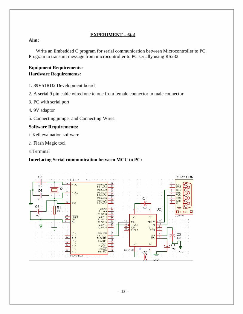
EXPERIMENT – 6(a)
Aim:
Write an Embedded C program for serial communication between Microcontroller to PC.
Program to transmit message from microcontroller to PC serially using RS232.
Equipment Requirements:
Hardware Requirements:
1. 89V51RD2 Development board
2. A serial 9 pin cable wired one to one from female connector to male connector
3. PC with serial port
4. 9V adaptor
5. Connecting jumper and Connecting Wires.
Software Requirements:
1. Keil evaluation software
2. Flash Magic tool.
3. Terminal
Interfacing Serial communication between MCU to PC:
- 44 -
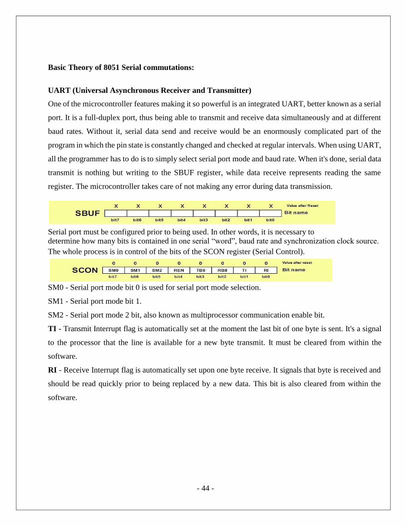
Basic Theory of 8051 Serial commutations:
UART (Universal Asynchronous Receiver and Transmitter)
One of the microcontroller features making it so powerful is an integrated UART, better known as a serial
port. It is a full-duplex port, thus being able to transmit and receive data simultaneously and at different
baud rates. Without it, serial data send and receive would be an enormously complicated part of the
program in which the pin state is constantly changed and checked at regular intervals. When using UART,
all the programmer has to do is to simply select serial port mode and baud rate. When it's done, serial data
transmit is nothing but writing to the SBUF register, while data receive represents reading the same
register. The microcontroller takes care of not making any error during data transmission.
Serial port must be configured prior to being used. In other words, it is necessary to
determine how many bits is contained in one serial ―word‖, baud rate and synchronization clock source.
The whole process is in control of the bits of the SCON register (Serial Control).
SM0 - Serial port mode bit 0 is used for serial port mode selection.
SM1 - Serial port mode bit 1.
SM2 - Serial port mode 2 bit, also known as multiprocessor communication enable bit.
TI - Transmit Interrupt flag is automatically set at the moment the last bit of one byte is sent. It's a signal
to the processor that the line is available for a new byte transmit. It must be cleared from within the
software.
RI - Receive Interrupt flag is automatically set upon one byte receive. It signals that byte is received and
should be read quickly prior to being replaced by a new data. This bit is also cleared from within the
software.
- 45 -
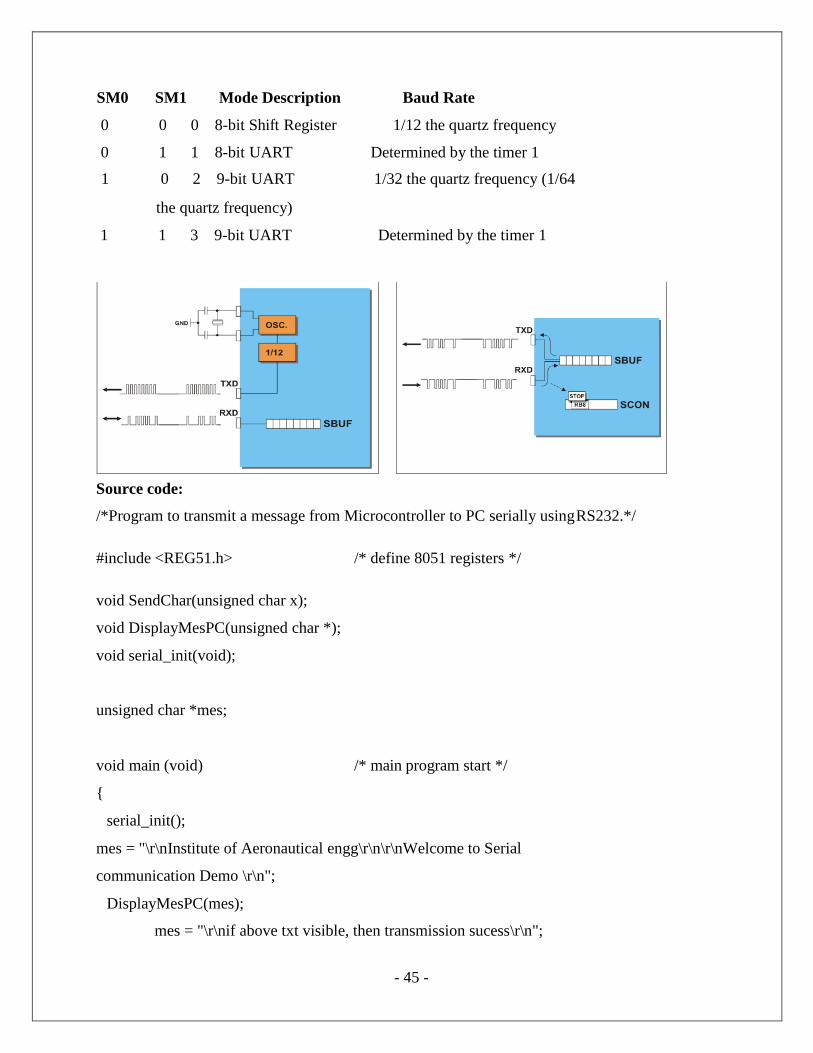
SM0 SM1 Mode Description Baud Rate
0 0 0 8-bit Shift Register 1/12 the quartz frequency
0 1 1 8-bit UART Determined by the timer 1
1 0 2 9-bit UART 1/32 the quartz frequency (1/64
the quartz frequency)
1 1 3 9-bit UART Determined by the timer 1
Source code:
/*Program to transmit a message from Microcontroller to PC serially using RS232.*/
#include <REG51.h> /* define 8051 registers */
void SendChar(unsigned char x);
void DisplayMesPC(unsigned char *);
void serial_init(void);
unsigned char *mes;
void main (void) /* main program start */
{
serial_init();
mes = "\r\nInstitute of Aeronautical engg\r\n\r\nWelcome to Serial
communication Demo \r\n";
DisplayMesPC(mes);
mes = "\r\nif above txt visible, then transmission sucess\r\n";
- 46 -
DisplayMesPC(mes);
while(1);
}
void SendChar(unsigned char x) // transmit function to send character to PC
{
SBUF =x; // wrting the character into the serial buffer
TI = 0; // Clearing the Transmit empty flag
while(!TI); // wating for end of trasmission. after transmission
the TI flag will set.
}
void DisplayMesPC(unsigned char *mes)
{
int counter;
for (counter=0;mes[counter]!='\0';counter++)
{
SendChar(mes[counter]);
}
}
void serial_init()
{
TMOD = 0x20; /* GATE OFF,C/#T = 0, M1 M0 = 10(8 BIT AUTO
RELOAD) TIMER 0 ,TIMER 1 IN MODE 2(AUTO RELOAD MODE)*/
SCON = 0x50; /* SERIAL PORT IN MODE2 8-BIT UART VARIABLE
BAUDRATE */
TH1 = 0xfd; /* TIMER 1 FOR BAUD RATE GEN(9.6K)*/
TR1 = 1; /* baud rate timer start*/
}
- 47 -
Flow chart:
Results/Output verification:
Now the program is running on Microcontroller. And the output can be seen in the board. You
can see terminal device .
- 48 -
EXPERIMENT – 6(b)
Aim:
Write an Embedded C program for serial communication between Microcontroller to PC.
Program to receive a message from PC to microcontroller serially using RS232.
Equipment Requirements:
Hardware Requirements:
1. 89V51RD2 Development board
2. A serial 9 pin cable wired one to one from female connector to male connector
3. PC with serial port
4. 9V adaptor
5. Connecting jumper and Connecting Wires.
Software Requirements:
1. Keil evaluation software
2. Flash Magic tool.
3. Terminal
Interfacing Serial communication between MCU to PC:
- 49 -
Basic Theory of 8051 Serial commutations:
UART (Universal Asynchronous Receiver and Transmitter)
One of the microcontroller features making it so powerful is an integrated UART, better known as a serial
port.
It is a full-duplex port, thus being able to transmit and receive data simultaneously and at different baud
rates. Without it, serial data send and receive would be an enormously complicated part of the program
in which the pin state is constantly changed and checked at regular intervals. When using UART, all the
programmer has to do is to simply select serial port mode and baud rate. When it's done, serial data
transmit is nothing but writing to the SBUF register, while data receive represents reading the same
register. The microcontroller takes care
of not making any error during data transmission.
Serial port must be configured prior to being used. In other words, it is necessary to
determine how many bits is contained in one serial ―word‖, baud rate and synchronization clock source.
The whole process is in control of the bits of the SCON register (Serial Control).
SM0 - Serial port mode bit 0 is used for serial port mode selection.
SM1 - Serial port mode bit 1.
SM2 - Serial port mode 2 bit, also known as multiprocessor communication enable bit.
TI - Transmit Interrupt flag is automatically set at the moment the last bit of one byte is sent. It's a
signal
to the processor that the line is available for a new byte transmit. It must be cleared from within the
software.
RI - Receive Interrupt flag is automatically set upon one byte receive. It signals that byte is received
and
should be read quickly prior to being replaced by a new data. This bit is also cleared from within the
software.
SM0 SM1 Mode Description Baud Rate
0 0 0 8-bit Shift Register 1/12 the quartz frequency
- 50 -
0 1 1 8-bit UART Determined by the timer 1
0 1 2 9-bit UART 1/32 the quartz frequency
1 1 3 9-bit UART Determined by the timer 1
Source code:
/*Program to receive a message from PC to microcontroller serially using RS232.*/
#include <reg51.h>
unsigned char ReceiveSerial() {
unsigned char c;
TMOD = 0x20; /* configure timer for the correct baud rate*/ TH1 = 0xe6; /*
1200 bps for 12 MHz clock */
TCON = 0x00; /* Set timer to not running */
SCON = 0x50; /* Set Serial IO to receive and normal mode */ TR1 = 1; /*
start timer to Receive */
while( (SCON & 0x01) == 0 ) /* wait for receive data */;
c = SBUF;
return c;
}
void main(void) {
unsigned char c;
while( 1 )
{
char ReceivSerial()
}
}
- 51 -
Flow chart:
Results/Output verification:
Now the program is running on Microcontroller. And the output can be seen in the board.
- 52 -
EXPERIMENT – 7
Program to interface Stepper Motor to rotate the motor in clockwise and anticlockwise directions
Aim:
Write a Embedded C Program to interface Stepper Motor to rotate the motor in clockwise and
anticlockwise directions
Equipment Requirements:
Hardware Requirements:
1. 89V51RD2 Development board
2. A serial 9 pin cable wired one to one from female connector to male connector
3. PC with serial port
4. 9V adaptor
5. Connecting jumper and Connecting Wires.
6.Stepper motor
Software Requirements:
1. Keil evaluation software
2. Flash Magic tool.
Stepper Motor Interfacing with 8051:
- 53 -
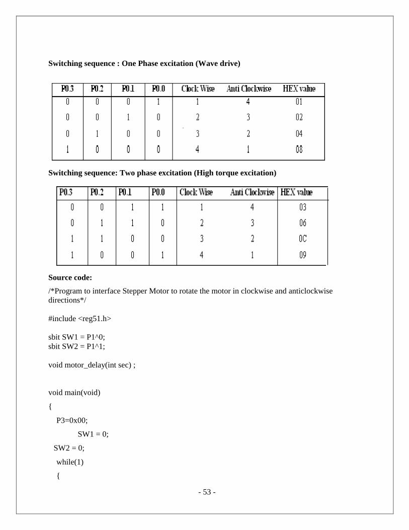
Switching sequence : One Phase excitation (Wave drive)
Switching sequence: Two phase excitation (High torque excitation)
Source code:
/*Program to interface Stepper Motor to rotate the motor in clockwise and anticlockwise
directions*/
#include <reg51.h>
sbit SW1 = P1^0;
sbit SW2 = P1^1;
void motor_delay(int sec) ;
void main(void)
{
P3=0x00;
SW1 = 0;
SW2 = 0;
while(1)
{
- 54 -
if(SW1 == 0)
{
P3 = 0x50;
motor_delay(2);
P3 = 0x90;
motor_delay(2);
P3 = 0xA0;
motor_delay(2);
P3 = 0x60;
motor_delay(2);
}
else if(SW2 == 0)
{
P3 = 0x60;
motor_delay(2);
P3 = 0xA0;
motor_delay(2);
P3 = 0x90;
motor_delay(2);
P3 = 0x50;
motor_delay(2);
}
}
}
void motor_delay(int sec)
{
int i,j,secd;
for (secd=0;secd<=sec;secd++)
for(i=0;i<=4;i++)
for (j= 0;j<=800;j++)
- 55 -
{
}
}
Result:
1. Connector the jumpers at the stepper motor driver IC.
2. Connect the switch pins to the port pins selected.
3. Connect the Stepper motor to the available pins beside the serial port.
- 56 -
EXPERIMENT – 8
Develop necessary interfacing circuit to read data from i) temperature sensor and process using 89c51
sdk, the data has to display terminal window
Aim:
Write a program to read data from temperature sensor and display the temperature value.
Equipment Requirements:
Hardware Requirements:
1. 89V51RD2 Development board
2. A serial 9 pin cable wired one to one from female connector to male connector
3. PC with serial port
4. 9V adaptor
5. Connecting jumper and Connecting Wires.
Software Requirements:
1. Keil evaluation software
2. Flash Magic tool.
3. Terminal device
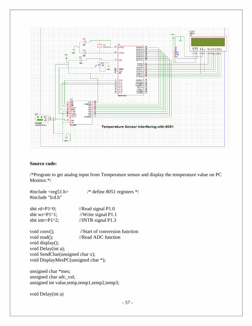
Temperature Sensor Interfacing with 8051:
- 57 -
Source code:
/*Program to get analog input from Temperature sensor and display the temperature value on PC
Monitor.*/
#include <reg51.h> /* define 8051 registers */
#include "lcd.h"
sbit rd=P1^0; //Read signal P1.0
sbit wr=P1^1; //Write signal P1.1
sbit intr=P1^2; //INTR signal P1.3
void conv(); //Start of conversion function
void read(); //Read ADC function void display();
void Delay(int a);
void SendChar(unsigned char x);
void DisplayMesPC(unsigned char *);
unsigned char *mes; unsigned char adc_val;
unsigned int value,temp,temp1,temp2,temp3;
void Delay(int a)
- 58 -
{ char i;
for(i=0;i<a;i++)
{ LCD_delay(250); LCD_delay(250);
}
}
void serial_init()
{ = 0x20; /* GATE OFF,C/#T = 0, M1 M0 = 10(8 BIT AUTO RELOAD)
TIMER 0 ,TIMER 1 IN 2(AUTO RELOAD MODE)*/
SCON = 0x50; /* SERIAL PORT IN MODE2 8-BIT UART VARIABLE BAUDRATE*/
TH1 = 0xfd; /* TIMER 1 FOR BAUD RATE GEN(9.6K)*/
TR1 = 1; /* baud rate timer start*/
}
void PowerOn( )
{
unsigned char inner, outer;
for (outer = 0x00; outer < 0x10; outer++)
{
for (inner = 0x00; inner < 0xFF; inner++); }
LCD_init();
for (inner = 0; inner < 10; inner++)
LCD_delay(2);
serial_init();
}
void main()
{
P0=0xFF;
P1=0x04;
PowerOn();
while(1)
{
- 59 -
LCD_clear();
LCD_row1();
LCD_puts("Temperature sensor "); DisplayMesPC("\r\nTemparature Value : ");
conv(); //Start conversion
read(); //Read ADC
display(); //Send the read value PC and LCD
Delay(4);
}
}
void conv()
{
wr = 0; //Make WR low
wr = 1; //Make WR high
while(intr); //Wait for INTR to go low
}
void read()
{
rd = 0; //Make RD low
adc_val = P0; //Read ADC port
rd = 1; //Make RD high
}
void display() { // display the adc vvalue in the form of milli volts
LCD_row2();
LCD_puts(" Temp :");
value=adc_val;
value=value*196; //since resolution is 5V/255=19.6mv
value=value/100; // 10 division by 196 instead 19.6 another 10 is 1*
corresponds 10mv
if(value>=1000)
{
temp=value/1000;
adc_val=temp+48;
LCD_putc(adc_val);
SendChar(adc_val);
}
temp1=value%1000;
if(temp1>=100&&temp1<=999){
temp=temp1;
- 60 -
temp=temp/100;
adc_val=temp+48;
LCD_putc(adc_val);
SendChar(adc_val);
}
Else
{
LCD_putc('0');
SendChar('0');
}
temp2=temp1%100;
if(temp2>=10&&temp2<=99)
{
temp=temp2;
temp=temp/10;
adc_val=temp+48;
LCD_putc(adc_val);
SendChar(adc_val);
}
else
{
LCD_putc('0');
SendChar('0');
}
temp3=temp2%10;
if(temp3>0&&temp3<10){
temp=temp3;
adc_val=temp+48;
LCD_putc(adc_val);
SendChar(adc_val);
}
else {
LCD_putc('0');
SendChar('0'); }
LCD_putc(0XDF);
SendChar('*');
SendChar(' ');
SendChar('C');
LCD_putc('*');
LCD_putc('C');
}
void SendChar(unsigned char x) // transmit function to send character to PC
- 61 -
{ SBUF =x; // wrting the character into the serial buffer
TI = 0; // Clearing the Transmit empty flag
while(!TI); // wating for end of trasmission. after transmission the TI flag will set. }
void DisplayMesPC(unsigned char *mes)
{
int counter; for(counter=0;mes[counter]!='\0';counter++)
{
SendChar(mes[counter]);
}
}
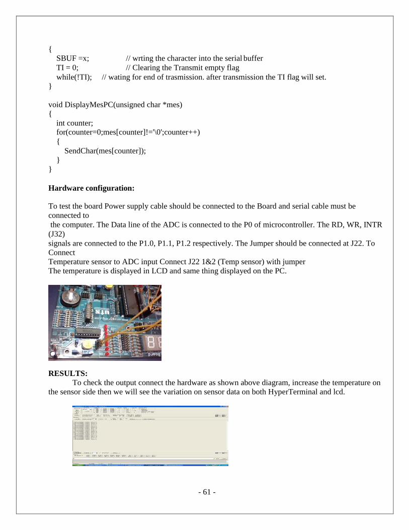
Hardware configuration:
To test the board Power supply cable should be connected to the Board and serial cable must be
connected to
the computer. The Data line of the ADC is connected to the P0 of microcontroller. The RD, WR, INTR
(J32)
signals are connected to the P1.0, P1.1, P1.2 respectively. The Jumper should be connected at J22. To
Connect
Temperature sensor to ADC input Connect J22 1&2 (Temp sensor) with jumper
The temperature is displayed in LCD and same thing displayed on the PC.
RESULTS:
To check the output connect the hardware as shown above diagram, increase the temperature on
the sensor side then we will see the variation on sensor data on both HyperTerminal and lcd.
- 62 -
EXPERIMENT –9
Write a Program to
Port RTOS on to 89V51 Microcontroller and verify. Run 2 to 3 tasks simultaneously on 89V51
SDK. Use LCD interface, LED interface, Serial communication.
Aim:
Write an Embedded C program to sort RTOS on to 89V51 Microcontroller and verify. Run 2
to 3 tasks simultaneously on P89V51RD2.Use LCD interface, LED interface, Serial communication.
Equipment Requirements:
Hardware Requirements:
1. 89V51RD2 Development board
2. A serial 9 pin cable wired one to one from female connector to male connector
3. PC with serial port
4. 9V adaptor
5. Connecting jumper and Connecting Wires.
Software Requirements:
1. Keil evaluation software
2. Flash Magic tool.
RTOS Introduction:
What is a real-time System?
Timeliness is the single most important aspect of a real -time system. These systems respond
to a series of external inputs, which arrive in an unpredictable fashion. The real-time systems process
these inputs, take appropriate decisions and also generate output necessary to control the peripherals
connected to them. As defined by Donald Gillies "A real-time system is one in which the correctness
of the computations not only depends upon the logical correctness of the computation but also upon
the time in which the result is produced. If the timing constraints are not met, system failure is said to
have occurred."
It is essential that the timing constraints of the system are guaranteed to be met. Guaranteeing
timing behavior requires that the system be predictable. The design of a real -time system must specify
the timing requirements of the system and ensure that the system performance is both correct and
timely. There are three types of time constraints:
Hard: A late response is incorrect and implies a system failure. An example of such a system is of
medical equipment monitoring vital functions of a human body, where a late response would be
considered as a failure.
Soft: Timeliness requirements are defined by using an average response e time. If a single
computation is late, it is not usually significant, although repeated late computation can result in
system failures. An example of such a system includes airlines reservation systems.
- 63 -
Firm: This is a combination of both hard and soft timeliness requirements. The computation has a
shorter soft requirement and a longer hard requirement. For example, a patient ventilator must
mechanically ventilate the patient a certain amount in a given time period. A few seconds' delay in the
initiation of breath is allowed, but not more than that.
Experimental procedure:
Open the keil IDE and do the same procedure like create new project and build the application.
Then open Flash magic and download the hex file. Please refer the above experimental procedure for
keil4 IDE. In this RTOS experiment we have to do few more settings for creating new project (if you
want to create new project then only do these settings),just follow the settings as below mentioned.
After creating new project file go to target and do these settings: SELECT TARGET and right
click on target settings and select RAM size is 0X0000 to 0X1000.Again go to settings and select C51
and select LEVEL 9. And do the below
Source code:
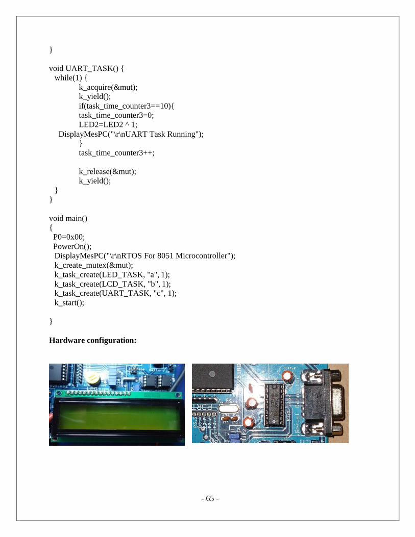
/*Port RTOS on to 89V51 Microcontroller and verify.
• Run 2 to 3 tasks simultaneously on 89V51 SDK.
• Use LCD interface, LED interface, Serial communication. */