Embedded Systems Design and Development Chapter 12 Embedded Systems - Design and Development ............................................................................. 3 Things to Look For… ................................................................................................................... 3 12.0 Introduction .......................................................................................................................... 4 12.1 System Design and Development ....................................................................................... 6 12.1.1 Getting Ready – Start Thinking .................................................................................... 7 12.1.2 Getting Started ............................................................................................................. 8 12.2 Life Cycle Models ................................................................................................................ 9 12.2.1 The Waterfall Model ................................................................................................... 10 12.2.2 The V Cycle Model ..................................................................................................... 11 12.2.3 The Spiral Model ........................................................................................................ 13 12.2.4 Rapid Prototyping - Incremental ................................................................................. 14 12.3 Problem Solving................................................................................................................. 15 12.3.1 Five Steps to Design .................................................................................................. 15 12.4 The Design Process .......................................................................................................... 16 12.5 Identifying the Requirements ............................................................................................. 18 12.6 Formulating the Requirements Specification ..................................................................... 21 12.6.1 The Environment ........................................................................................................ 22 12.6.2 The System ................................................................................................................ 23 12.7 The System Design Specification ...................................................................................... 35 12.7.1 The System ................................................................................................................ 35 12.8 System Specifications versus System Requirements ....................................................... 50 12.8 System Specifications versus System Requirements ....................................................... 51 12.9 Partitioning and Decomposing a System........................................................................... 52 12.9.1 Initial Thoughts ........................................................................................................... 52 12.9.2 Coupling ..................................................................................................................... 55 12.9.3 Cohesion .................................................................................................................... 57 12.9.4 More Considerations .................................................................................................. 59 12.10 Functional Design ............................................................................................................ 59 12.11 Architectural Design......................................................................................................... 66 12.11.1 Hardware and Software Specification and Design................................................... 67 12.12 Functional Model versus Architectural Model .................................................................. 71 12.12.1 The Functional Model ............................................................................................... 72 12.12.2 The Architectural Model ........................................................................................... 72 12.12.3 The Need for Both Models ....................................................................................... 72 12.13 Prototyping....................................................................................................................... 73 Embedded Systems- A Contemporary Design Tool Copyright 2004 Oxford Consulting, Ltd. - 1 -
Transcript
Embedded Systems Design and Development Chapter 12
Embedded Systems - Design and Development .............................................................................3
Things to Look For… ...................................................................................................................3
Embedded Systems Design and Development Chapter 12
A Simple Example:
Years ago, when developing some of the early microprocessor based embedded systems, we would encounter problems as we debugged the hardware and software. At that time, tools were few and far between. This was a new field.
One very powerful tool for helping to track down such problems is called a logic analyzer. It allows one to follow which instructions the processor is executing (in real-time) and learn why stuff goes in and never comes out. We had to have one, so, our company purchased two of them from two different vendors.
The analyzer from vendor A arrived was out of the box, on the bench, connected to the system, and making useful measurements within 10-15 minutes. Only several days later did anyone think to take a look at the manual. The analyzer from vendor B had a user interface that rivaled a 1040 tax form. Its one-inch thick manual was equally cryptic and demanded several hours of study before even the simplest measurements could be made.
Guess which instrument always has a queue of people waiting to use it and guess which vendor sold us many more instruments.
12.1 System Design and Development
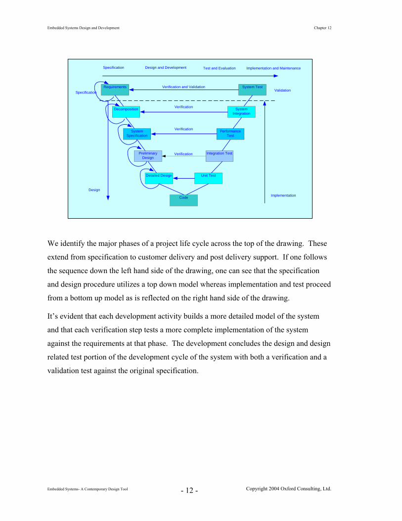
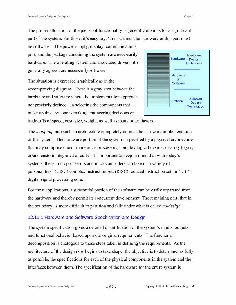
System design and development is a challenging problem. What makes it fun and
exciting is that there is a very large creative component to it. There are no rules, no steps
to follow to make one creative. There is, however, a large collection of rules to ensure
the opposite. Consider a new child. Each comes into this world, eyes wide open with a
million questions. Why is the sky blue? Why is the sun yellow? Why can’t we see the
air? Where does air come from anyway? What do we do? We put them in school. We
teach them the rules. Walk into any group of little ones and ask, how many of you can
sing? How many of you can draw? Almost every tiny hand leaps up. Go into any
similar group of adults and ask the same questions. Everyone is suddenly fascinated with
their shoes. One hand may come slowly up. Why? We place too many restrictions on
our thinking. Sure, we may need 10 million dollars worth of electronic equipment to give
our voice perfect pitch, but, so what. We need to remove artificial restrictions that we
Embedded Systems Design and Development Chapter 12
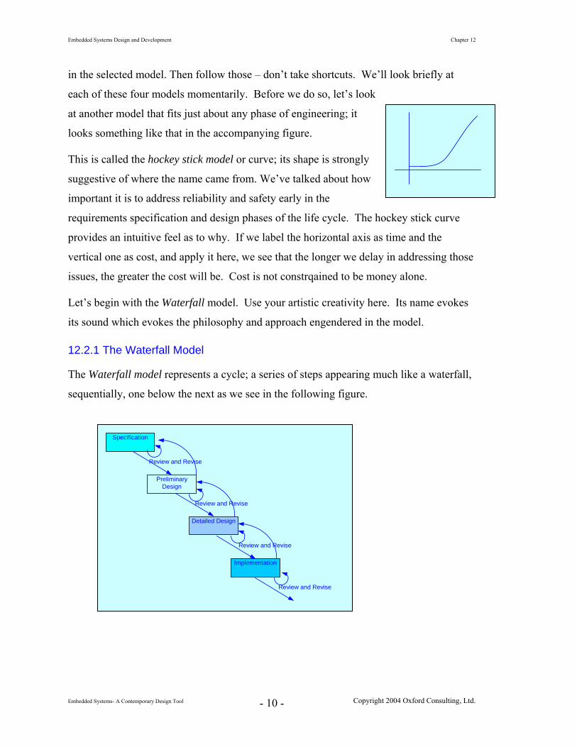
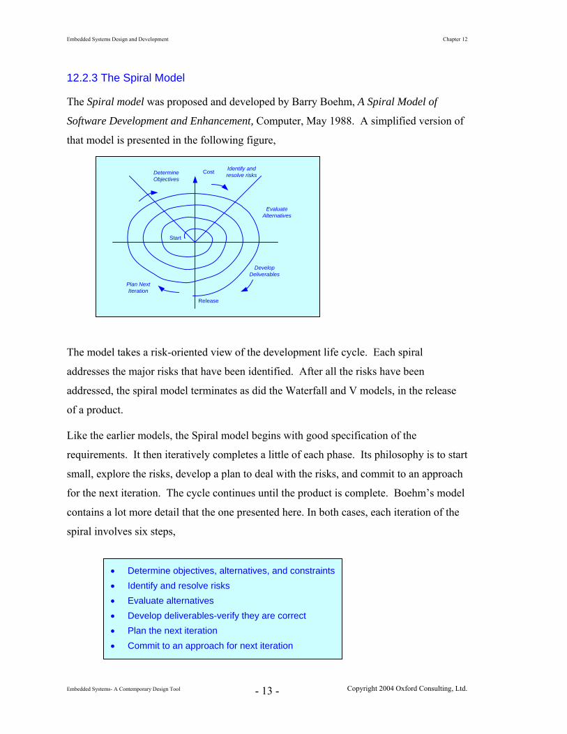
12.2.3 The Spiral Model
The Spiral model was proposed and developed by Barry Boehm, A Spiral Model of
Software Development and Enhancement, Computer, May 1988. A simplified version of
that model is presented in the following figure,
Cost Identify andresolve risks
Plan NextIteration
EvaluateAlternatives
DetermineObjectives
DevelopDeliverables
Start
Release
The model takes a risk-oriented view of the development life cycle. Each spiral
addresses the major risks that have been identified. After all the risks have been
addressed, the spiral model terminates as did the Waterfall and V models, in the release
of a product.
Like the earlier models, the Spiral model begins with good specification of the
requirements. It then iteratively completes a little of each phase. Its philosophy is to start
small, explore the risks, develop a plan to deal with the risks, and commit to an approach
for the next iteration. The cycle continues until the product is complete. Boehm’s model
contains a lot more detail that the one presented here. In both cases, each iteration of the
spiral involves six steps,
• Determine objectives, alternatives, and constraints• Identify and resolve risks • Evaluate alternatives • Develop deliverables-verify they are correct • Plan the next iteration • Commit to an approach for next iteration
Embedded Systems Design and Development Chapter 12
Because there is not one right answer, the problem represents a challenge and an
opportunity to be creative. A colleague who worked on numerous designs of a particular
piece of measurement technology once said, ‘although each design performs exactly the
same function, each also represents an opportunity to explore a new approach that is
better than the old.’ That colleague built a career around doing what everyone else said
couldn’t be done…including some of the top names in the industry.
One of the best ways to learn how to do something it is simply to do it. So, let’s get
started. As we walk through each of the steps in the design process that we’ve identified,
we’ll see how they apply to the following design. We begin with a textual description.
As a senior development engineer at Your Time is Our Frequency, Ltd.com. You’ve just finished one project and are now getting ready to head off to the next. As part of the early planning of that project, you and one of the marketing folks are traveling around the country talking with people from a number of different engineering firms. You are trying to determine what features your customers would like to see in the next generation product.
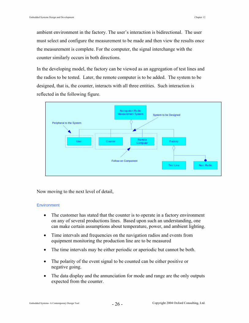
You’ve been on the road with this guy for a couple of weeks now and are anxious to get home. All the cities are beginning to look exactly alike. Tuesday, this must be Cleveland…hmmm, looks just like the last three cities, oh well. This is the last customer for this trip. This morning, you’re talking with High Flying Avionics, Inc. They’re interested in a new counter that can be used on several of their avionics production lines.
Following several hours of discussion with one of the manufacturing managers, you identify most of their requirements. Your discussion with them follows.
Embedded Systems Design and Development Chapter 12
Business is a little slow right now and money is tight, so we don’t have a large budget to purchase a lot of different new instruments. In fact, ideally, we’d like to be able to use the same instrument on several of our lines.
Today, we have our technicians running most of the tests manually, but, in future, we’d like to be able to automate as many of these tests as we can. As we upgrade our systems, we’d like to be able to operate several of these counters remotely from a single PC. Here are some of the other things that we’d like to be able to do.
As part of our ongoing efforts to improve production and flow through our lines, we monitor the rate at which units arrive into each of the major assembly areas. To do that, we need to be able to track how many of our navigation radios come down a production line each hour. Because we support small quantity builds of different kinds of radios, the rate at which the units come past the monitoring points is not constant. As each radio arrives at an entry point, it breaks an IR beam. On most of the lines, breaking the beam generates a 1 μsec wide, negative going 5.0 V pulse. However, we do have several older lines that we must still support. On these, the pulse is positive going.
On several of the newer lines, we have to measure frequency up to 150.000 MHz. We also have several tests for which we must measure frequencies in the range of 50KHz ± 0.001 KHz and 100 Hz with 0.001 Hz resolution. On another line, we have several instruments with output signals that have a duration up to 1.0000 ± 0.0001ms and others that have a duration of up to 9.999 to 10.000 ms and up to 1.000 ± 0.001sec. These signals are not periodic. Finally, we have several periodic signals on those same units that we must be able to measure with the same accuracy and resolution.
12.5 Identifying the Requirements
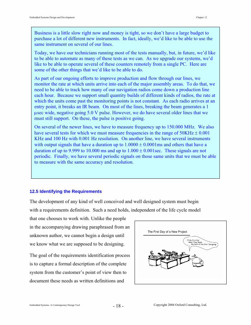
The development of any kind of well conceived and well designed system must begin
with a requirements definition. Such a need holds, independent of the life cycle model
that one chooses to work with. Unlike the people
in the accompanying drawing paraphrased from an
unknown author, we cannot begin a design until
we know what we are supposed to be designing.
The goal of the requirements identification process
is to capture a formal description of the complete
Embedded Systems Design and Development Chapter 12
• The assumption is made that the signals to be measured are independent of one another.
• In future, commands will be sent from a computer to the counter to direct itsoperation. Da
ta will be sent from the counter to the computer.
Cou
• The counter must have the ability to measure time intervals, frequencies, and count events.
her periodic or
and ut signals.
off or until the user makes another
•
.
inclusion of the ability irect its operation.
l lay.
The next st
designed.
nter
to
• The frequencies are fixed but, span a range of values.
• The time intervals span a range of values and may be eitaperiodic but cannot be both.
• The counter will support the ability for the user to manually select modemeasurement range for all inp
• The counter will continue to make and display the selected attribute of the signal until power to the system is turnedselection.
The counter will measure only one signal at a time.
• An event can be modeled as an aperiodic time signal
• The design will be sufficiently flexible to allow future to send commands from a computer to the counter to d
• The response of the counter to remote commands will be the same as its response to front panel selections with the exception that measured data wilbe sent from the counter to the computer as well as to the front panel disp
ep is to formalize, in a specification, what is known about the system to be
The document, the System Requirements Specification, opens with a summary
Embedded Systems Design and Development Chapter 12
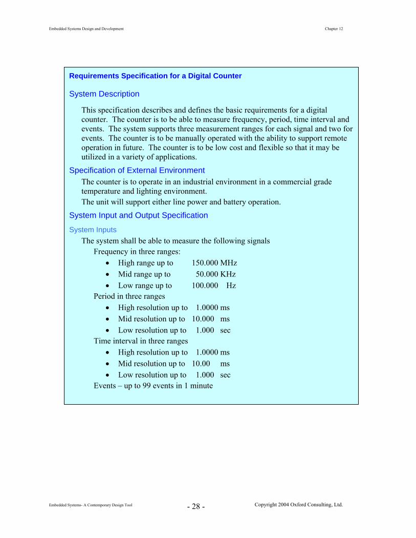
Requirements Specification for a Digital Counter
System Description
This specification describes and defines the basic requirements for a digital counter. The counter is to be able to measure frequency, period, time interval and events. The system supports three measurement ranges for each signal and two for events. The counter is to be manually operated with the ability to support remote operation in future. The counter is to be low cost and flexible so that it may be utilized in a variety of applications.
Specification of External Environment The counter is to operate in an industrial environment in a commercial grade temperature and lighting environment. The unit will support either line power and battery operation.
System Input and Output Specification
System Inputs The system shall be able to measure the following signals
Frequency in three ranges: • High range up to 150.000 MHz • Mid range up to 50.000 KHz • Low range up to 100.000 Hz
Period in three ranges • High resolution up to 1.0000 ms • Mid resolution up to 10.000 ms • Low resolution up to 1.000 sec
Time interval in three ranges • High resolution up to 1.0000 ms • Mid resolution up to 10.00 ms • Low resolution up to 1.000 sec
Embedded Systems Design and Development Chapter 12
Trigger Edge
Frequency, Period, and Events
Rising or Falling edge
Time Interval
Rising to rising edge
Falling to falling edge
Rising to falling edge
Falling to rising edge
Reset
Power ON/OFF
The measurement results shall be presented on a 6 digit display; leading zeros will be suppressed. The display shall be readable in direct sunlight and from any angle.
Embedded Systems Design and Development Chapter 12
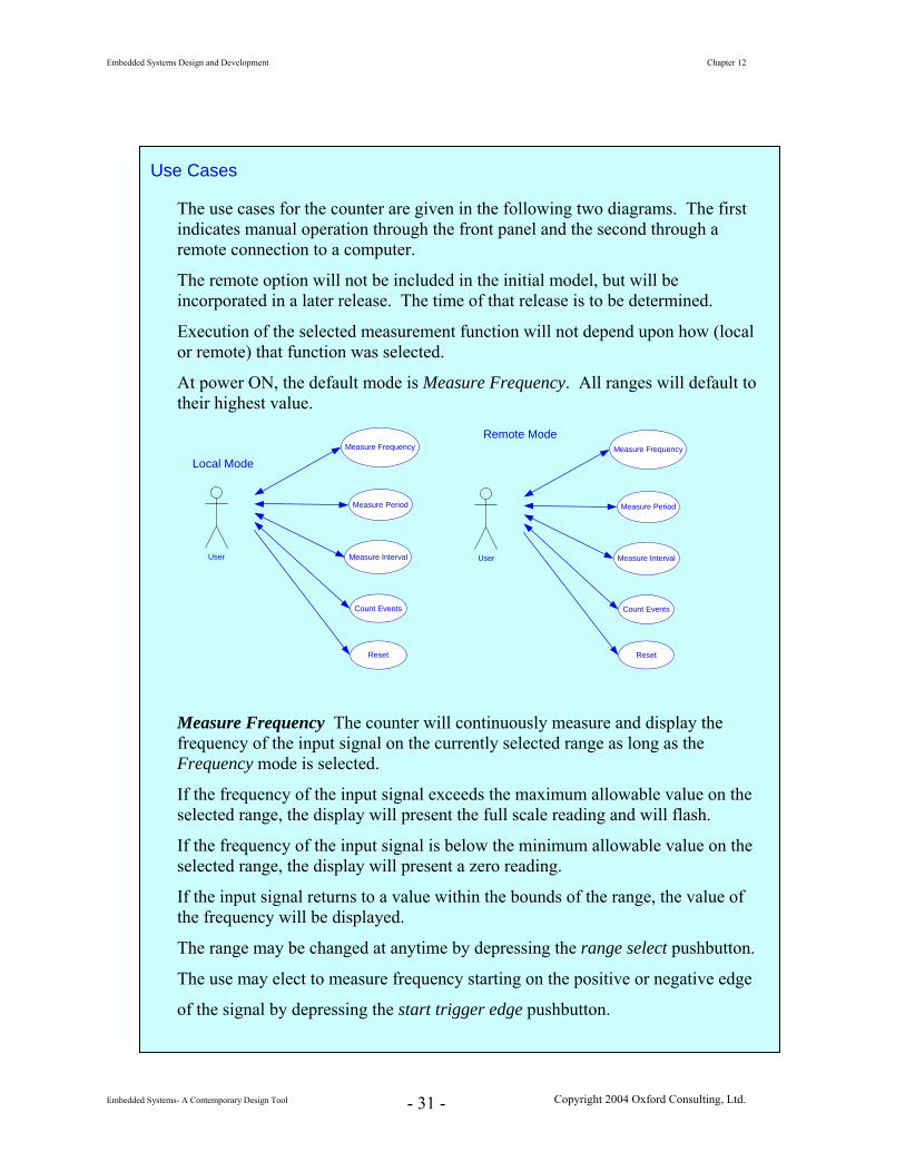
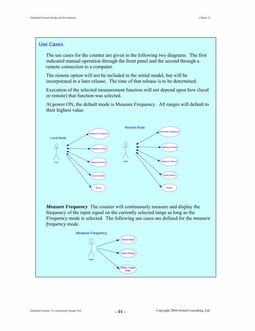
Use Cases
The use cases for the counter are given in the following two diagrams. The first indicates manual operation through the front panel and the second through a remote connection to a computer.
The remote option will not be included in the initial model, but will be incorporated in a later release. The time of that release is to be determined.
Execution of the selected measurement function will not depend upon how (local or remote) that function was selected.
At power ON, the default mode is Measure Frequency. All ranges will default to their highest value.
User
Measure Frequency
Measure Period
Measure Interval
Count Events
Local Mode
Reset
Remote Mode
User
Measure Frequency
Measure Period
Measure Interval
Count Events
Reset
Measure Frequency The counter will continuously measure and display the frequency of the input signal on the currently selected range as long as the Frequency mode is selected.
If the frequency of the input signal exceeds the maximum allowable value on the selected range, the display will present the full scale reading and will flash.
If the frequency of the input signal is below the minimum allowable value on the selected range, the display will present a zero reading.
If the input signal returns to a value within the bounds of the range, the value of the frequency will be displayed.
The range may be changed at anytime by depressing the range select pushbutton.
The use may elect to measure frequency starting on the positive or negative edge
of the signal by depressing the start trigger edge pushbutton.
Embedded Systems Design and Development Chapter 12
Measure Period The counter will continuously measure and display the period of the input signal on the currently selected range as long as the Period mode is selected.
If the period of the input signal exceeds the maximum allowable value on the selected range, the display will present the full scale reading and will flash. If the period of the input signal is below the minimum allowable value on the selected range, the display will present a zero reading.
If the input signal returns to a value within the bounds of the range, the value of the period will be displayed.
The range may be changed at anytime by depressing the range select pushbutton.
The use may elect to measure period starting on the positive or negative edge of the signal by depressing the start trigger edge pushbutton.
Measure Interval The counter will continuously measure and display the duration of the selected portion of the input signal on the currently selected range as long as the Interval mode is selected.
If the duration of the selected portion of the input signal exceeds the maximum allowable value on the selected range, the display will present the full scale reading and will flash.
If the duration of the selected portion of the input signal is below the minimum allowable value on the selected range, the display will display zero.
If the input signal returns to a value within the bounds of the range, the value of the duration of the selected portion of the input signal will be displayed.
The range may be changed at anytime by depressing the range select pushbutton.
The user may elect to commence measuring the interval on the positive or negative edge of the signal by depressing the start trigger edge pushbutton.
The user may elect to terminate the measurement interval on the positive or negative edge of the signal by depressing the stop trigger edge pushbutton.
Note that the signal duration from positive edge to positive edge or negative edge to negative edge is the same as the period of the signal.
Events The counter will continuously count and display the number of occurrences of the input signal on the currently selected range. The accumulated count will be reset to 0 at the end of the select count duration.
The range may be changed at anytime by depressing the range select pushbutton.
The user may elect to increment the count on the on the positive or negative edge of the input signal by depressing the start trigger edge pushbutton.
If the number of accrued counts exceeds the maximum allowable value on the selected range, the display will present the full scale reading and will flash.
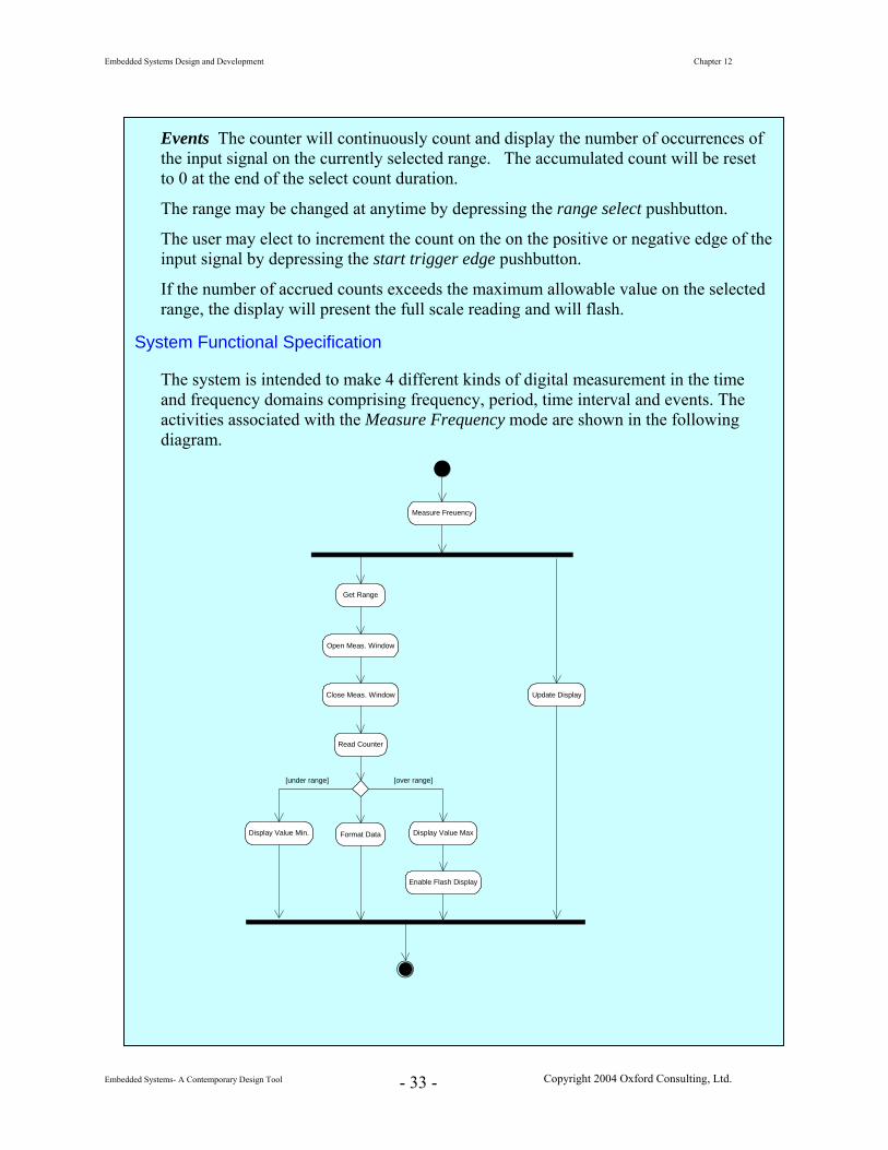
System Functional Specification
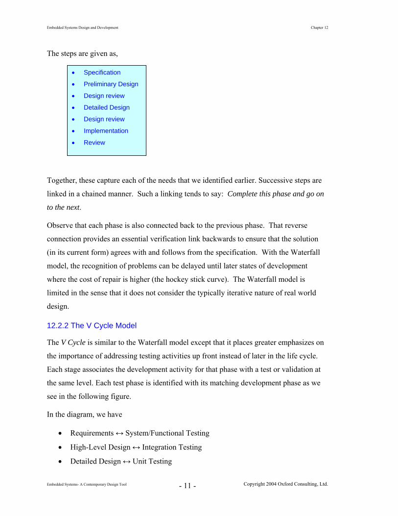
The system is intended to make 4 different kinds of digital measurement in the time and frequency domains comprising frequency, period, time interval and events. The activities associated with the Measure Frequency mode are shown in the following diagram.
Measure Freuency
Get Range
Open Meas. Window
Close Meas. Window
Read Counter
Display Value Min. Display Value Max
Enable Flash Display
Format Data
Update Display
[under range] [over range]
Embedded Systems Design and Development Chapter 12
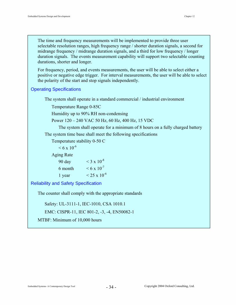
The time and frequency measurements will be implemented to provide three user selectable resolution ranges, high frequency range / shorter duration signals, a second for midrange frequency / midrange duration signals, and a third for low frequency / longer duration signals. The events measurement capability will support two selectable counting durations, shorter and longer.
For frequency, period, and events measurements, the user will be able to select either a positive or negative edge trigger. For interval measurements, the user will be able to select the polarity of the start and stop signals independently.
Operating Specifications
The system shall operate in a standard commercial / industrial environment
Temperature Range 0-85C Humidity up to 90% RH non-condensing Power 120 – 240 VAC 50 Hz, 60 Hz, 400 Hz, 15 VDC
The system shall operate for a minimum of 8 hours on a fully charged battery The system time base shall meet the following specifications
Temperature stability 0-50 C < 6 x 10⁻⁶
Aging Rate 90 day < 3 x 10⁻⁸
6 month < 6 x 10⁻⁷
1 year < 25 x 10-6
Reliability and Safety Specification
The counter shall comply with the appropriate standards
Embedded Systems Design and Development Chapter 12
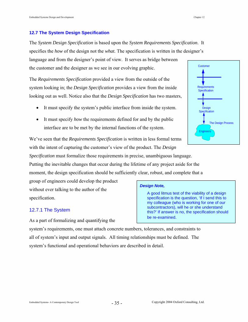
12.7 The System Design Specification
The System Design Specification is based upon the System Requirements Specification. It
specifies the how of the design not the what. The specification is written in the designer’s
language and from the designer’s point of view. It serves as bridge between
the customer and the designer as we see in our evolving graphic.
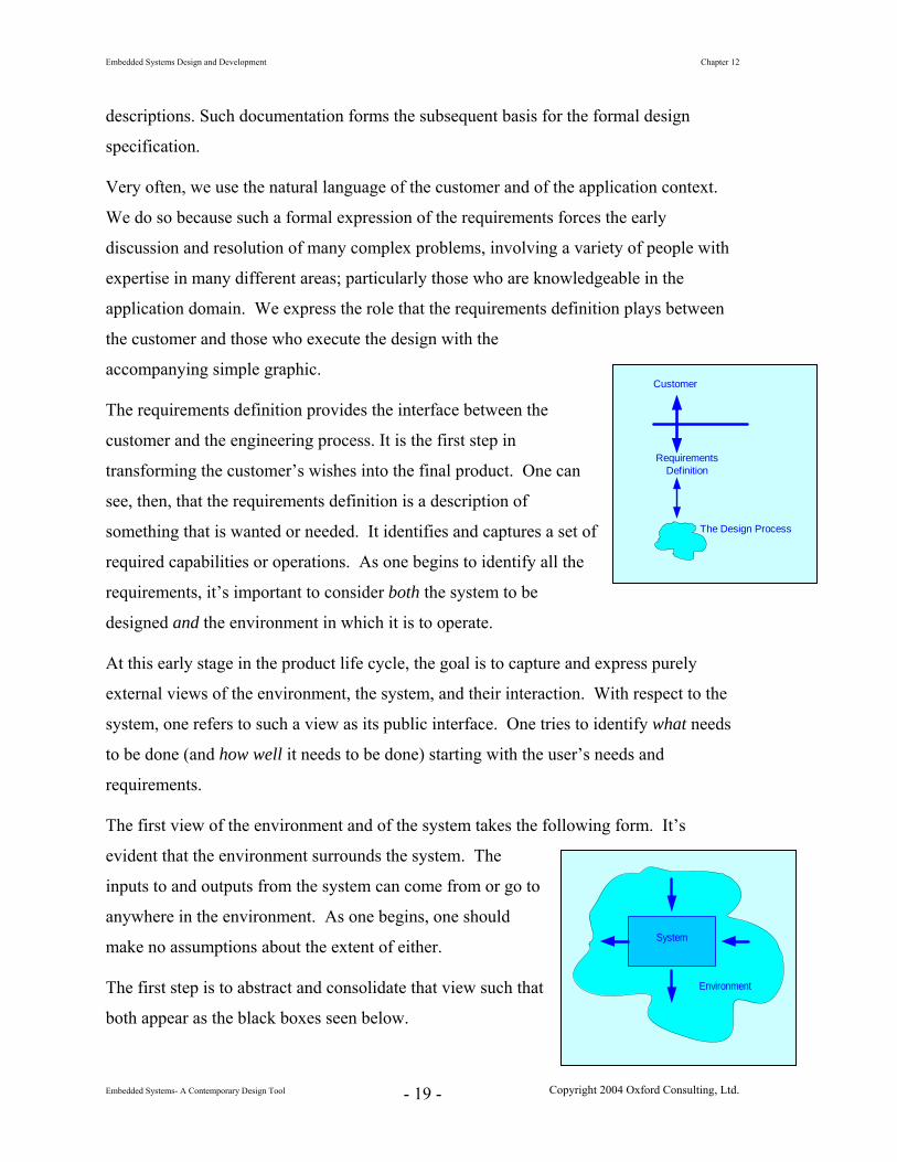
The Requirements Specification provided a view from the outside of the
system looking in; the Design Specification provides a view from the inside
looking out as well. Notice also that the Design Specification has two masters,
• It must specify the system’s public interface from inside the system.
• It must specify how the requirements defined for and by the public
interface are to be met by the internal functions of the system.
We’ve seen that the Requirements Specification is written in less formal terms
with the intent of capturing the customer’s view of the product. The Design
Specification must formalize those requirements in precise, unambiguous language.
Putting the inevitable changes that occur during the lifetime of any project aside for the
moment, the design specification should be sufficiently clear, robust, and complete that a
group of engineers could develop the product
without ever talking to the author of the
specification.
12.7.1 The System
As a part of formalizing and quantifying the
system’s requirements, one must attach concrete numbers, tolerances, and constraints to
all of system’s input and output signals. All timing relationships must be defined. The
system’s functional and operational behaviors are described in detail.
Customer
RequirementsSpecification
Engineers
DesignSpecification
The Design Process
Design Note,
A good litmus test of the viability of a design specification is the question, ‘If I send this to my colleague (who is working for one of our subcontractors), will he or she understand this?’ If answer is no, the specification should be re-examined.
Embedded Systems Design and Development Chapter 12
12.7.1.1 Quantifying the System
The quantification of the system’s characteristics begins with the inputs and outputs,
based upon the specified requirements. The necessary technical details are added to
enable the engineer to accurately and faithfully execute the actual design.
• System Inputs and Outputs For each I/O variable, the following are specified
The Name of the signal
The use of the signal as an input or output
The nature of the signal as an event, data, state variable, etc.
Starting with the requirements specification, we provide detailed descriptions as necessary and incorporate any additional technical or technological constraints that may be needed.
The complete specification of the signal including nominal value, range, level tolerances, timing, timing tolerances.
The interrelationships with other signals including any constraints on those relationships.
• Responsibilities – Activities
Functional and Operational Specifications
The functional and operational specifications that will quantify the dynamic
behavior of the system are now formulated. The functional requirements
specification identifies the major functions that the system must perform from a
high level view. The operational specification endeavors to capture specific
details of how those functions behave within the context of the operating
environment.
The manner in which a particular function must operate, the conditions imposed
on the operation, and the range of that operation are now captured. The
specification must consider concrete numbers – precisions and tolerances.
All variables in the functional specification, all operating conditions, and all
ordinary and extraordinary operating modes must be quantified. The specification
Embedded Systems Design and Development Chapter 12
Let’s now bring everything together,
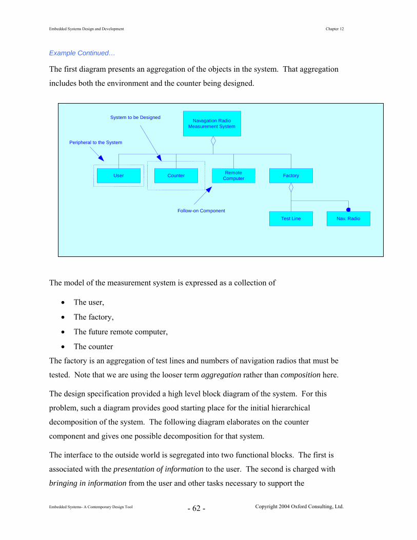
Example Continued…
We’ll now continue with the development of the counter. The Design Specification
will follow, but extend, what has been captured in the Requirements Specification.
The focus will now be on providing specific numbers, ranges, and tolerances for
signals that are within the system.
Once again, we’ll put together any thoughts about the environment and the system
prior to writing the specification.
Environment
Specifications relating to the environment have been discussed earlier. There are
no changes here.
Counter
• When specifying measurement and stimulus equipment, the specifications for that equipment are generally 10 times (one order of magnitude) better than for the signals that must be measured or generated.
That margin is provided when specifying the range and tolerances on the counter’s measurement capabilities.
• Specifications on counting events are based upon the granularity of the timing of the interval during which the events are counted.
• The values to be displayed at the measurement boundaries are now defined.
The next step is to provide any additional detail that may be needed and to fully
This specification describes and defines the detailed design requirements for a digital counter. The counter is to be able to measure frequency, period, time interval and events. The system supports three measurement ranges for each signal and two for events. The counter is to be manually operated with the ability to support remote operation in future. The counter is to be low cost and flexible so that it may be utilized in a variety of applications.
Specification of External Environment The counter is to operate in an industrial environment in a commercial grade temperature and lighting environment.
The unit will support either line power and battery operation.
Specific details are included under Operating Specifications.
System Input and Output Specification
System Inputs The system shall be able to measure the following signals
Frequency in three ranges: • High range up to 150.000 MHz • Mid range up to 50.000 KHz • Low range up to 100.000 Hz
Period in three ranges • High resolution up to 1.0000 ms • Mid resolution up to 10.000 ms • Low resolution up to 1.000 sec
Time interval in three ranges • High resolution up to 1.0000 ms • Mid resolution up to 10.00 ms • Low resolution up to 1.000 sec
Events • Events to 99 per minute • Signal level 0-4.0 V ± 0.5 V • Transition time 10 ns ≤ τrise, τfall ≤ 50 ns
Embedded Systems Design and Development Chapter 12
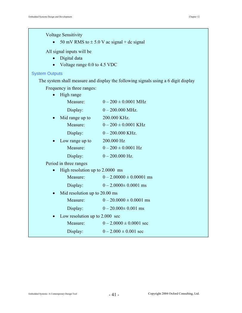
Voltage Sensitivity • 50 mV RMS to ± 5.0 V ac signal + dc signal
All signal inputs will be • Digital data • Voltage range 0.0 to 4.5 VDC
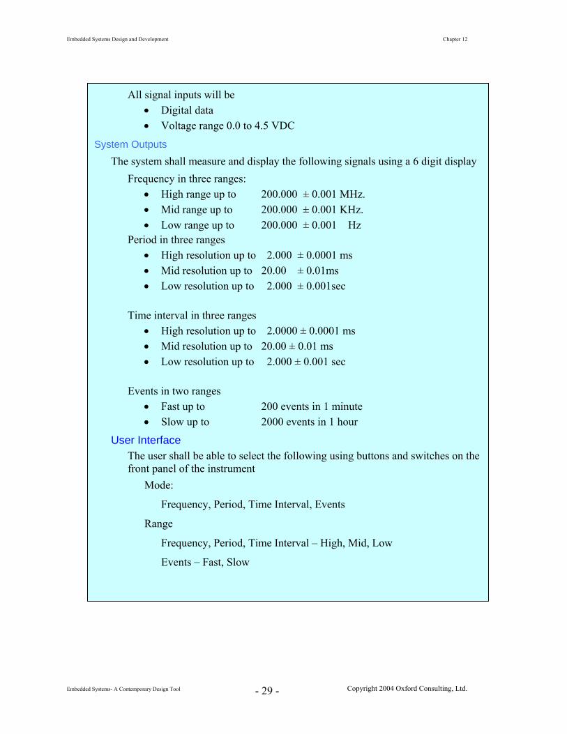
System Outputs
The system shall measure and display the following signals using a 6 digit display Frequency in three ranges:
• High range Measure: 0 – 200 ± 0.0001 MHz
Display: 0 – 200.000 MHz. • Mid range up to 200.000 KHz.
Measure: 0 – 200 ± 0.0001 KHz
Display: 0 – 200.000 KHz. • Low range up to 200.000 Hz
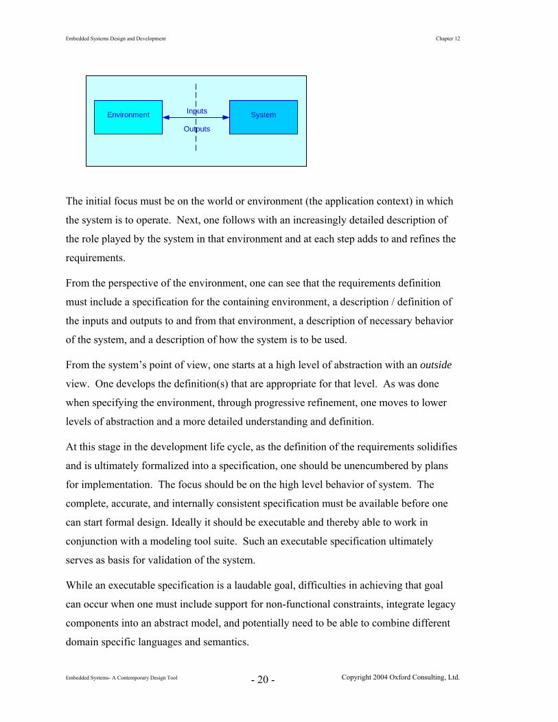
Measure: 0 – 200 ± 0.0001 Hz
Display: 0 – 200.000 Hz. Period in three ranges
• High resolution up to 2.0000 ms Measure: 0 – 2.00000 ± 0.00001 ms
Display: 0 – 2.0000± 0.0001 ms
• Mid resolution up to 20.00 ms Measure: 0 – 20.0000 ± 0.0001 ms
Display: 0 – 20.000± 0.001 ms • Low resolution up to 2.000 sec
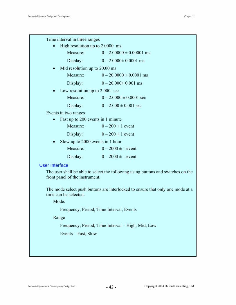
Time interval in three ranges • High resolution up to 2.0000 ms
Measure: 0 – 2.00000 ± 0.00001 ms
Display: 0 – 2.0000± 0.0001 ms • Mid resolution up to 20.00 ms
Measure: 0 – 20.0000 ± 0.0001 ms
Display: 0 – 20.000± 0.001 ms • Low resolution up to 2.000 sec
Measure: 0 – 2.0000 ± 0.0001 sec
Display: 0 – 2.000 ± 0.001 sec Events in two ranges
• Fast up to 200 events in 1 minute Measure: 0 – 200 ± 1 event
Display: 0 – 200 ± 1 event • Slow up to 2000 events in 1 hour
Measure: 0 – 2000 ± 1 event
Display: 0 – 2000 ± 1 event
User Interface The user shall be able to select the following using buttons and switches on the front panel of the instrument. The mode select push buttons are interlocked to ensure that only one mode at a time can be selected.
Mode:
Frequency, Period, Time Interval, Events
Range
Frequency, Period, Time Interval – High, Mid, Low
Events – Fast, Slow
Embedded Systems Design and Development Chapter 12
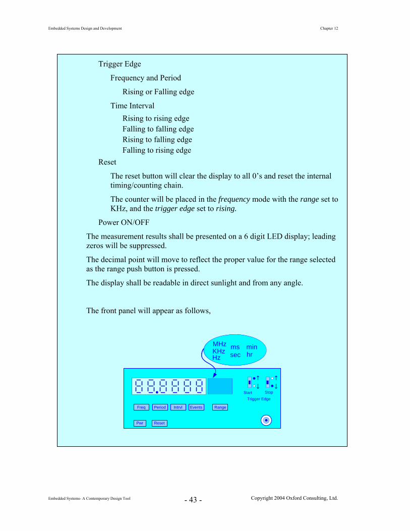
Time Interval Rising to rising edge Falling to falling edge Rising to falling edge Falling to rising edge
Reset
The reset button will clear the display to all 0’s and reset the internal timing/counting chain.
The counter will be placed in the frequency mode with the range set to KHz, and the trigger edge set to rising.
Power ON/OFF
The measurement results shall be presented on a 6 digit LED display; leading zeros will be suppressed.
The decimal point will move to reflect the proper value for the range selected as the range push button is pressed.
The display shall be readable in direct sunlight and from any angle.
The front panel will appear as follows,
Freq Period Intrvl Events
Start
Pwr
MHzKHzHz
mssec
Range
Trigger EdgeStop
minhr
Freq Period Intrvl Events
Start
Pwr
MHzKHzHz
mssec
Range
Trigger EdgeStop
minhr
Reset
Embedded Systems Design and Development Chapter 12
Use Cases
The use cases for the counter are given in the following two diagrams. The first indicated manual operation through the front panel and the second through a remote connection to a computer.
The remote option will not be included in the initial model, but will be incorporated in a later release. The time of that release is to be determined.
Execution of the selected measurement function will not depend upon how (local or remote) that function was selected.
At power ON, the default mode is Measure Frequency. All ranges will default to their highest value.
User
Measure Frequency
Measure Period
Measure Interval
Count Events
Local Mode
Reset
Remote Mode
User
Measure Frequency
Measure Period
Measure Interval
Count Events
Reset
Measure Frequency The counter will continuously measure and display the frequency of the input signal on the currently selected range as long as the Frequency mode is selected. The following use cases are defined for the measure frequency mode.
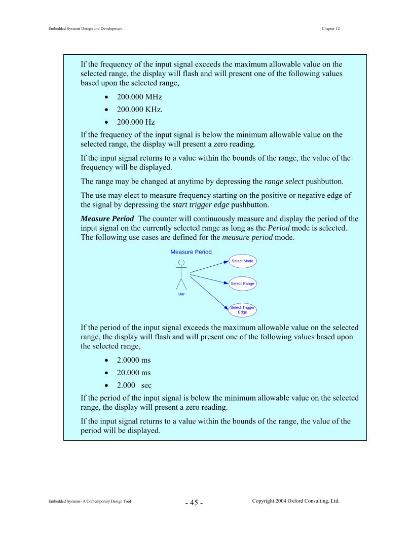
If the frequency of the input signal exceeds the maximum allowable value on the selected range, the display will flash and will present one of the following values based upon the selected range,
• 200.000 MHz • 200.000 KHz. • 200.000 Hz
If the frequency of the input signal is below the minimum allowable value on the selected range, the display will present a zero reading.
If the input signal returns to a value within the bounds of the range, the value of the frequency will be displayed.
The range may be changed at anytime by depressing the range select pushbutton.
The use may elect to measure frequency starting on the positive or negative edge of the signal by depressing the start trigger edge pushbutton.
Measure Period The counter will continuously measure and display the period of the input signal on the currently selected range as long as the Period mode is selected. The following use cases are defined for the measure period mode.
Uer
Select Mode
Select Range
Select TriggerEdge
Measure Period
If the period of the input signal exceeds the maximum allowable value on the selected range, the display will flash and will present one of the following values based upon the selected range,
• 2.0000 ms • 20.000 ms • 2.000 sec
If the period of the input signal is below the minimum allowable value on the selected range, the display will present a zero reading.
If the input signal returns to a value within the bounds of the range, the value of the period will be displayed.
Embedded Systems Design and Development Chapter 12
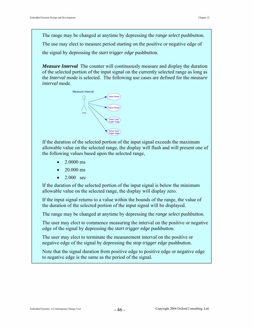
The range may be changed at anytime by depressing the range select pushbutton.
The use may elect to measure period starting on the positive or negative edge of
the signal by depressing the start trigger edge pushbutton.
Measure Interval The counter will continuously measure and display the duration of the selected portion of the input signal on the currently selected range as long as the Interval mode is selected. The following use cases are defined for the measure interval mode.
User
Select Mode
Select Range
Select StartTrigger Edge
Measure Interval
Select StopTrigger Edge
If the duration of the selected portion of the input signal exceeds the maximum allowable value on the selected range, the display will flash and will present one of the following values based upon the selected range,
• 2.0000 ms • 20.000 ms • 2.000 sec
If the duration of the selected portion of the input signal is below the minimum allowable value on the selected range, the display will display zero.
If the input signal returns to a value within the bounds of the range, the value of the duration of the selected portion of the input signal will be displayed.
The range may be changed at anytime by depressing the range select pushbutton.
The user may elect to commence measuring the interval on the positive or negative edge of the signal by depressing the start trigger edge pushbutton.
The user may elect to terminate the measurement interval on the positive or negative edge of the signal by depressing the stop trigger edge pushbutton.
Note that the signal duration from positive edge to positive edge or negative edge to negative edge is the same as the period of the signal.
Events The counter will continuously count and display the number of occurrences of the input signal on the currently selected range. The accumulated count will be reset to 0 at the end of the select count duration. The following use cases are defined for the count events mode.
User
Select Mode
Select Range
Select CountEdge
Count Events
If the number of accrued counts exceeds the maximum allowable value on the selected range, the display will flash and will present one of the following values based upon the selected range,
• 200 min • 2000 hour
The range may be changed at anytime by depressing the range select pushbutton.
The user may elect to increment the count on the on the positive or negative edge of the input signal by depressing the start trigger edge pushbutton.
System Functional Specification
The system is intended to make 4 different kinds of digital measurements comprising frequency, period, time interval and events.
The time and frequency measurements will be implemented to provide three user selectable resolution ranges, high frequency range / shorter duration signals, a second for midrange frequency / midrange duration signals, and a third for low frequency / longer duration signals. The events measurement capability will support two selectable counting durations, shorter and longer.
For frequency, period, and events measurements, the user will be able to select either a positive or negative edge trigger. For interval measurements, the user will be able to select the polarity of the start and stop signals independently.
The system will be designed so as not to preclude the incorporation of a remote access option in future.
Embedded Systems Design and Development Chapter 12
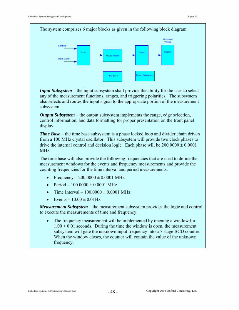
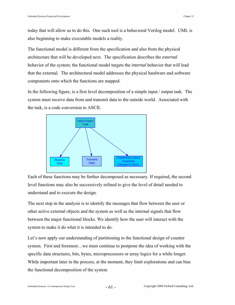
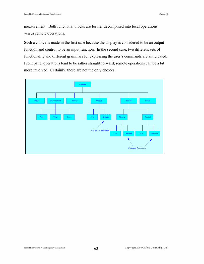
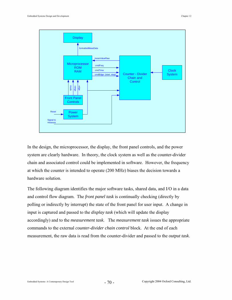
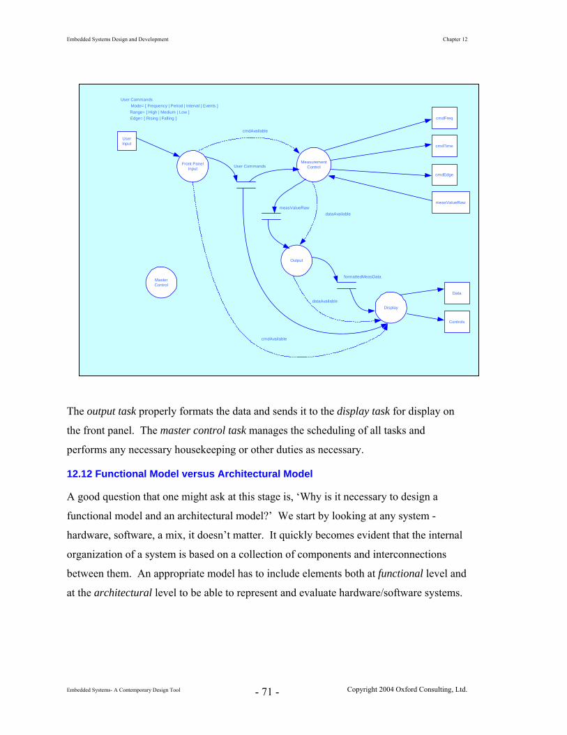
The system comprises 6 major blocks as given in the following block diagram.
Input Output
Time Base
Measurement
Power Subsystem
Display
Controls
Input Signal
MeasuredValues
Input Subsystem – the input subsystem shall provide the ability for the user to select any of the measurement functions, ranges, and triggering polarities. The subsystem also selects and routes the input signal to the appropriate portion of the measurement subsystem.
Output Subsystem – the output subsystem implements the range, edge selection, control information, and data formatting for proper presentation on the front panel display.
Time Base – the time base subsystem is a phase locked loop and divider chain driven from a 100 MHz crystal oscillator. This subsystem will provide two clock phases to drive the internal control and decision logic. Each phase will be 200.0000 ± 0.0001 MHz.
The time base will also provide the following frequencies that are used to define the measurement windows for the events and frequency measurements and provide the counting frequencies for the time interval and period measurements.
• Frequency – 200.0000 ± 0.0001 MHz • Period – 100.0000 ± 0.0001 MHz • Time Interval – 100.0000 ± 0.0001 MHz • Events – 10.00 ± 0.01Hz
Measurement Subsystem – the measurement subsystem provides the logic and control to execute the measurements of time and frequency.
• The frequency measurement will be implemented by opening a window for 1.00 ± 0.01 seconds. During the time the window is open, the measurement subsystem will gate the unknown input frequency into a 7 stage BCD counter. When the window closes, the counter will contain the value of the unknown frequency.
Embedded Systems Design and Development Chapter 12
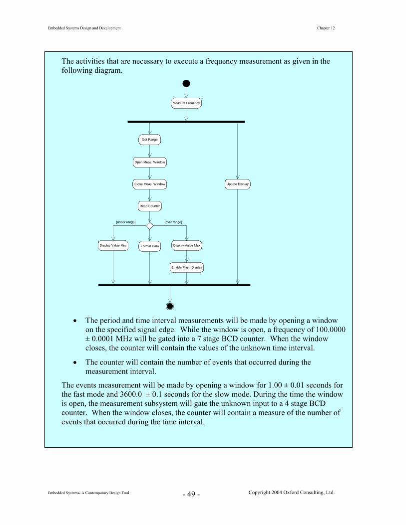
The activities that are necessary to execute a frequency measurement as given in the following diagram.
Measure Freuency
Get Range
Open Meas. Window
Close Meas. Window
Read Counter
Display Value Min. Display Value Max
Enable Flash Display
Format Data
Update Display
[under range] [over range]
• The period and time interval measurements will be made by opening a window
on the specified signal edge. While the window is open, a frequency of 100.0000 ± 0.0001 MHz will be gated into a 7 stage BCD counter. When the window closes, the counter will contain the values of the unknown time interval.
• The counter will contain the number of events that occurred during the measurement interval.
The events measurement will be made by opening a window for 1.00 ± 0.01 seconds for the fast mode and 3600.0 ± 0.1 seconds for the slow mode. During the time the window is open, the measurement subsystem will gate the unknown input to a 4 stage BCD counter. When the window closes, the counter will contain a measure of the number of events that occurred during the time interval.
Embedded Systems Design and Development Chapter 12
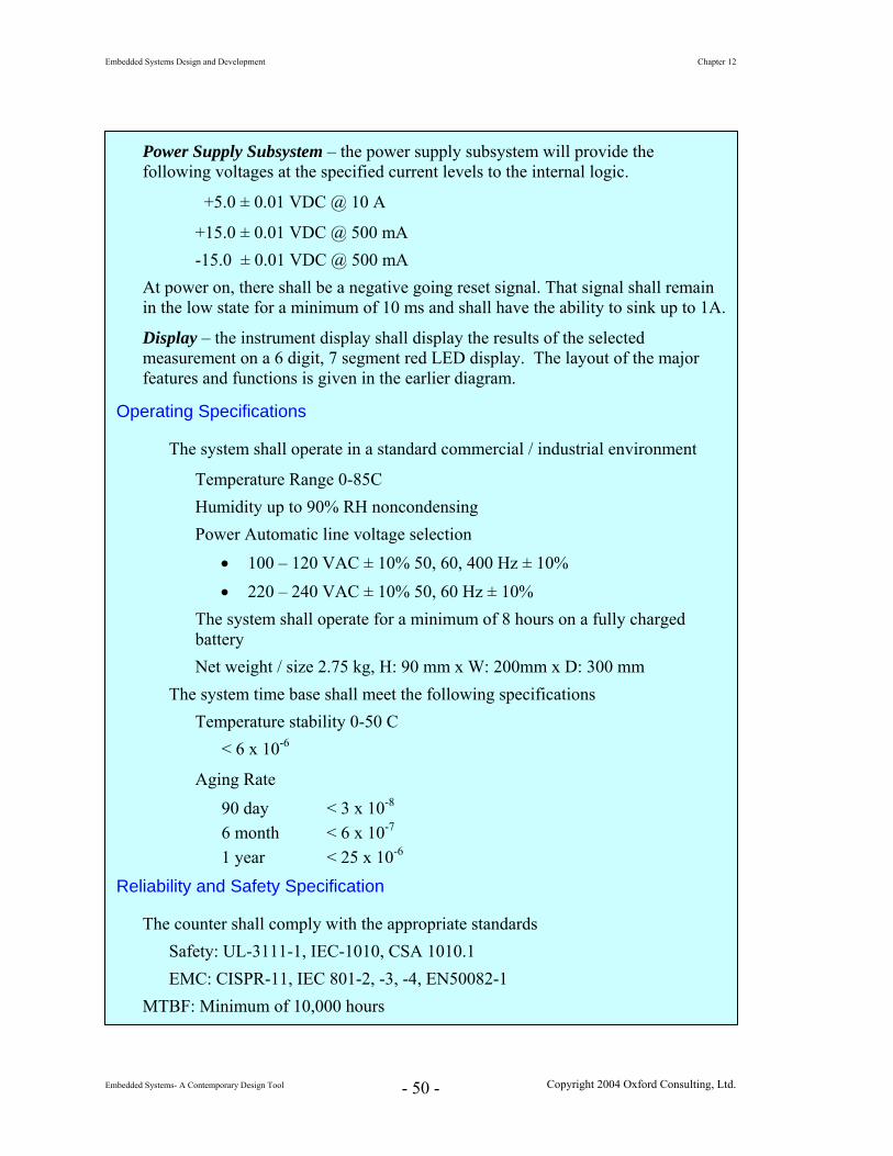
Power Supply Subsystem – the power supply subsystem will provide the following voltages at the specified current levels to the internal logic.
+5.0 ± 0.01 VDC @ 10 A
+15.0 ± 0.01 VDC @ 500 mA -15.0 ± 0.01 VDC @ 500 mA
At power on, there shall be a negative going reset signal. That signal shall remain in the low state for a minimum of 10 ms and shall have the ability to sink up to 1A.
Display – the instrument display shall display the results of the selected measurement on a 6 digit, 7 segment red LED display. The layout of the major features and functions is given in the earlier diagram.
Operating Specifications
The system shall operate in a standard commercial / industrial environment
Temperature Range 0-85C Humidity up to 90% RH noncondensing Power Automatic line voltage selection
Embedded Systems Design and Development Chapter 12
• Debugging the design during development
• Troubleshooting the system in the event of field failures,
• Maintaining the modules and system, and
• Modifying the design to add features or capabilities.
The major goal is to make the system’s modules as independent as possible – the goal is
to reduce or minimize coupling.
Design Heuristic The lower the coupling, the better job that has been done during partitioning.
Here are several things to think about during the early stages of the design to help to
1. Eliminate all unessential interaction between modules.
is not a part the intended
2. Minimize the amount of essential interaction between modules.
arly analysis
d
Some of the ways to help to reduce complexity include:
a. Reduce the number of interconnections between modules and thereby
b. ate.
c. bles. A better method is to pass
uch sharing is critical to meeting time constraints.
reduce coupling:
If a particular piece of functionality or shared parameter
task of two modules, then eliminate it.
While this sounds the same as the previous point, it’s not. If an e
establishes that some interaction with another module is necessary, effort shoul
be made to reduce the complexity of that required interface. The goal is to keep
things simple.
reduce the number of pieces of data that must flow between modules.
Try to take the most direct route to a signal or piece of data as appropri
There are some cases for which the best implementation is to use a proxy as an interface to a signal or piece of data. In general, however, it’s best toreduce the number of modules involved.
In general, avoid using shared global variadata into a module via its parameter list or calling interface.
With embedded applications, however, there are times when s
Embedded Systems Design and Development Chapter 12
d. things simple.
when an
3. Loosen
Unless s a high degree of coordination between several
ation, simply pass
12.9.3
An idea related to coupling is cohesion. The notion of coupling addresses the
; cohesion addresses bringing the pieces together. Cohesion is
goal is to
d
id
1960s. A number of years of refinement and integration of the ideas of many people
Avoid arcane interconnections between or amongst modules. A guiding principle underlying all design is to keep
e. Don’t hard code values into a module’s parameter list or calling interface unless absolutely necessary. We must do so on occasioninterface module or port must be at a specific address location; don’t makethis a general practice.
the essential interaction between modules, if possible.
the environment demand
modules to accomplish a task or to ensure error free communic
the module the information necessary to get the job done. Thereafter, wait for an
indication that the task has completed. Execute some other part of the task.
Cohesion
partitioning of a system
measure of strength of the functional relatedness of elements in a module. The
create strong, highly cohesive modules whose elements are genuinely and tightly relate
to one another. Conversely, elements should not be strongly related to elements in
another module. We want to maximize cohesion and minimize coupling.
The use of cohesion as a reliability and quality metric has been around since the m
studying various designs and design approaches led Constantine and Yordon (Y and C
1979 Page-Jones) to formulate a cohesion scale based upon an ease of maintenance
Embedded Systems Design and Development Chapter 12
Let’s look at several different kinds of cohesion.
We compare the different kinds of cohesion and coupling from several different
perspectives in the following. The ranking is Excellent/Easy = 5…Poor/Difficult = 1
Functional Cohesion – The module implements a single task and all comprising elements contribute to the execution of that one task.
Sequential Cohesion – The module implements a task as a sequential set of procedures. The output data of each procedure becomes the input data to the next. All of the comprising elements are involved in one of those procedures.
Communicational Cohesion – The module implements a task that has a number of procedures working on the same set of input data such as an image processing task.
Procedural Cohesion – The module implements a number of procedures that may or may not be related to a common activity. Control, rather than data, flows from one procedure to the next.
Temporal Cohesion – The module implements a number of unrelated procedures or activities that are sequentially ordered in time.
Logical Cohesion – The module implements a number of procedures that are possible alternative methods for accomplishing a task. A subset of those alternatives is selected by an outside user to actually execute the task.
Co-incidental Cohesion – The module aggregates a number of unrelated procedures. Such cohesion - or lack thereof should not be used.