Embedded systems Bernard Boigelot E-mail : [email protected]WWW : http://www.montefiore.ulg.ac.be/ ˜ boigelot/ http://www.montefiore.ulg.ac.be/ ˜ boigelot/courses/embedded/ References : • An Embedded Software Primer , David E. Simon, Addison-Wesley, 1999. • μC/OS-III: The Real-Time Kernel , Jean J. Labrosse, Micriμm Press, 2010. • Real-Time Systems , Jane W. S. Liu, Prentice Hall, 2000. 1
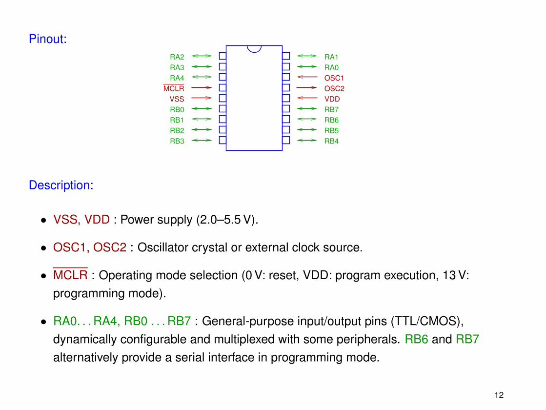
• RA0. . . RA4, RB0 . . . RB7 : General-purpose input/output pins (TTL/CMOS),dynamically configurable and multiplexed with some peripherals. RB6 and RB7alternatively provide a serial interface in programming mode.
12
Example of application: Temperature alarm
100nF
33pF 33pFPiezo
7805
+
+
1N4001
10µF
220R
LEDNTC
PIC 16F7169V
10K22K
22K
10K
4MHzOSC2
OSC1
RA1
RA0
RB1
RB2
VSS
VDD
RB0MCLR
Reset Test
13
Example of embedded bus
Problem: Managing data transfers between several devices (CPU, memory, sensors,peripherals, . . . ) using communication hardware that is as simple as possible.
Requirements:
• Bus topology.
• Small number of communication lines.
• Flexible configuration.
• Mechanisms for addressing devices, managing transactions, for performing arbitrationand flow control.
14
Solution: I2C bus
Principles:
• The bus consists of a pair of two-way lines: SDA (Serial DAta) and SCL (Serial Clock).
• The value of each line stays high whenever it is unused.
• Each device connected to the bus can read the value of SDA and SCL, but is only ableto force them down, i.e., to write a low value.
Device 1 Device 2
SDA
SCL
VCC
15
I2C: Transactions
The master of a transaction is responsible for
• generating a clock signal on SCL during the transaction.
• signaling the beginning (Start, S) and the end (Stop, P) of the transaction. The signalsS and P correspond to the two possible transitions of SDA when SCL is high.
When a transaction is in progress (i.e., between S and P), transitions of SDA are onlyallowed when SCL is low.
Illustration:
S P
SDA
SCL
16
I2C: Data transfers
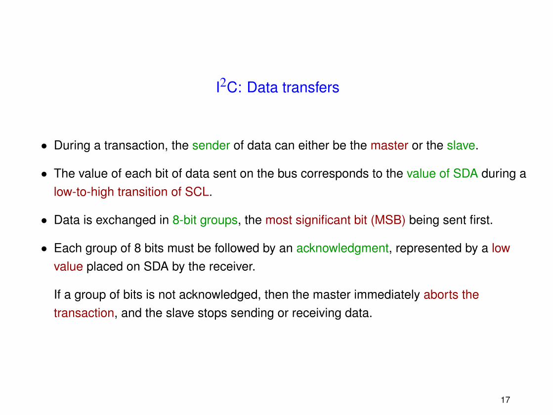
• During a transaction, the sender of data can either be the master or the slave.
• The value of each bit of data sent on the bus corresponds to the value of SDA during alow-to-high transition of SCL.
• Data is exchanged in 8-bit groups, the most significant bit (MSB) being sent first.
• Each group of 8 bits must be followed by an acknowledgment, represented by a lowvalue placed on SDA by the receiver.
If a group of bits is not acknowledged, then the master immediately aborts thetransaction, and the slave stops sending or receiving data.
17
I2C: Addressing
When a transaction is initiated, the master has to specify which device is the otherparticipant.
Principles:
• The first 8 bits exchanged in a transaction are always sent by the master.
• The first 7 bits of this group correspond to the address of the intended slave.
• The 8th bit then specifies the direction of the following data transfer:
– 0 : The master is the sender;
– 1 : The master is the receiver.
Remark: The first group of 8 bits must thus be acknowledged by the addressed slave,regardless of the data transfer direction.
18
I2C: Arbitration
It is possible to have several devices attempting to initiate transactions at the same time, bygenerating simultaneous Start signals.
For detecting potential conflicts, each master constantly monitors the value of SDA when itsends data. If the observed value differs from the sent one, then the master performing thisobservation immediately and silently withdraws from the transaction.
Remarks:
• A conflict can only be detected by the device that sends a high value.
• Transmitting simultaneously two exactly identical frames does not lead to a conflict!
19
I2C: Flow control
In some cases, the frequency of the clock signal generated is too high to be followed by theslave.
In such situations, the slave can request the master to permanently or temporarily slowdown the clock. This can be done by stretching the low value of SCL until the slave is readyagain to send or receive data.
When the master releases SCL while the clock is stretched, it detects that the value of SCLstays low, and pauses its operations until this line is released by the slave.
Illustration:
SCL
released by the master
released by the slave
20
Multiplexed input/output pins
Most microcontrollers allow to dynamically configure input/output pins in software.
Examples of typical configurations:
VCC
A/D
Digital input
Digital input with pull-up
Schmitt trigger
Analog inputD/A
GND
Three-state output
Open-drain output
Analog output
This feature makes is possible to build simple circuits in which the processor can interactwith a large number of peripherals.
21
Example: Digital multimeter
The problem is to interface a microcontroller offering only 12 dynamically configurableinput/output pins with:
• a screen composed of four 7-segment displays,
• a keyboard organized as a 4 × 4 matrix,
• 4 analog input channels.
(Source: Microchip application note AN557)
22
Solution:
• The screen and the keyboard are scanned: At a given time, one can only display asingle digit, or read a single column of keys.
• An additional phase is inserted for reading input channels.
• 4 pins are associated to both an input channel and a screen digit. They arealternatively configured as analog inputs (when reading channels) and digital outputs(when displaying a digit or reading the keyboard).
• The 8 remaining pins drive the screen segments during display and channel readingphases (8 digital outputs), and are also able to the scan the keyboard (4 digital outputs+ 4 digital inputs with pull-up).
23
Schematics:
MCU
24
Chapter 3
Interrupts
25
Introduction
An interrupt is a signal that requests the processor to temporarily suspend programexecution, in order to execute an interrupt routine.
Advantages:
• A very short response time to solicitations is achievable.
• Urgent operations can be programmed independently from the main code.
Interrupts can be triggered either by an exterior component:
• Interrupt ReQuest (IRQ), received from dedicated input pins,
• change of logic value at digital input pins,
26
or by the processor itself:
• timer expiration,
• arithmetic or instruction exception,
• software interrupt request,
• . . .
27
The interrupt mechanism
Upon receiving and accepting to service an interrupt request, the processor performs thefollowing operations:
1. The execution of the current instruction terminates.
2. A pointer to the next instruction to be executed is stored on the runtime stack.
3. The address of the interrupt routine is read from the appropriate interrupt vector(according to the source of the interrupt request).
4. The interrupt routine is executed.
5. At the end of the interrupt routine, the processor resumes program execution, at theaddress retrieved from the stack.
28
Interrupt control
Some critical operations can never be interrupted. It is then necessary to temporarilydisable interrupts prior to their execution, and to enable them again afterwards.
Some processors allow to assign specific priorities to interrupts originating from differentsources. Such architectures generally provide a mechanism for disabling the interruptshaving a priority less than some specified threshold. Interrupt priorities are also used forresolving simultaneous interrupt requests.
Enabling and disabling interrupts is performed by executing specific instructions, or bysetting the value of dedicated registers.
Notes:
• At power-on, interrupts are disabled by default, in order to allow correct initialization ofthe program.
29
• When an interrupt is triggered, some processors automatically disable all interrupts ofless or equal priority. They have to be explicitly reenabled in the interrupt routine ifneeded.
• When an interrupt request is received, the processor sets interrupt flags, in order totrigger the interrupt as soon as it becomes enabled. Interrupt flags have to be clearedexplicitly by the interrupt routine.
• Some architectures provide an interrupt source that cannot be disabled (NonMaskable Interrupt, NMI). Its usage is limited to exceptional situations (e.g., backingup critical data upon detecting an imminent power failure).
30
Saving and restoring context
The correct operation of a program must not be influenced by interrupts triggered during itsexecution.
It is thus mandatory for interrupt routines to leave the processor state unchanged: values ofregisters and flags, interface configuration, status of peripherals, . . . , must not be modified.
This is achieved by saving the context at the beginning of interrupt routines, and restoring itat the end.
Notes:
• The context is either saved on the execution stack or in a specific memory area.
• Some processors automatically save the context (either totally or in part) when aninterrupt is triggered.
31
• Context save and restore operations can sometimes be simplified by using dedicatedinstructions.
• The processors that automatically disable interrupts when branching to an interruptroutine enable them again as a side effect of context restoration.
32
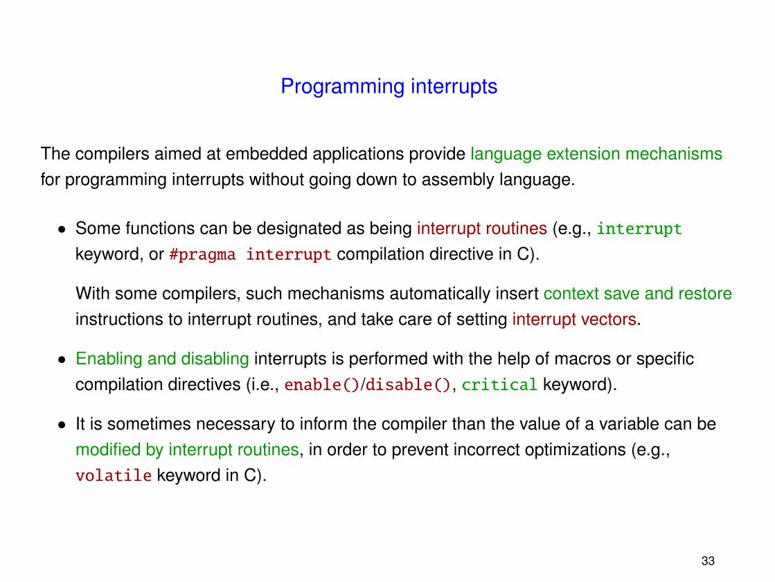
Programming interrupts
The compilers aimed at embedded applications provide language extension mechanismsfor programming interrupts without going down to assembly language.
• Some functions can be designated as being interrupt routines (e.g., interruptkeyword, or #pragma interrupt compilation directive in C).
With some compilers, such mechanisms automatically insert context save and restoreinstructions to interrupt routines, and take care of setting interrupt vectors.
• Enabling and disabling interrupts is performed with the help of macros or specificcompilation directives (i.e., enable()/disable(), critical keyword).
• It is sometimes necessary to inform the compiler than the value of a variable can bemodified by interrupt routines, in order to prevent incorrect optimizations (e.g.,volatile keyword in C).
33
Communicating with interrupt routines
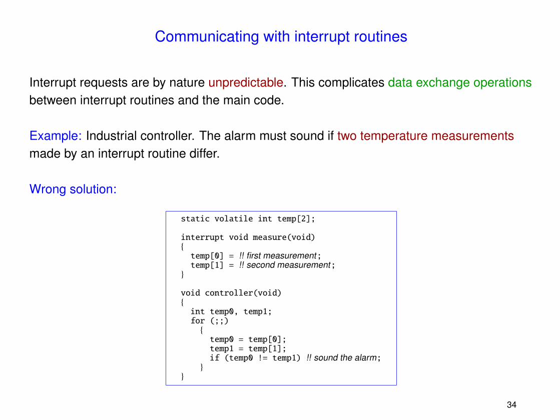
Interrupt requests are by nature unpredictable. This complicates data exchange operationsbetween interrupt routines and the main code.
Example: Industrial controller. The alarm must sound if two temperature measurementsmade by an interrupt routine differ.
Wrong solution:
static volatile int temp[2];
interrupt void measure(void){temp[0] = !! first measurement;temp[1] = !! second measurement;
• Carrying out the comparison between the two measurements in a single C instructiondoes not solve the problem:
...void controller(void){for (;;)if (temp[0] != temp[1]) !! sound the alarm;
}...
(Indeed, such an instruction is generally compiled into several machine instructions.)
• Even in programs written in assembly language, it is possible for the execution ofindividual instructions to be interrupted before their completion.
This only happens with specific instructions, often repeatedly performing a simpleroperation (e.g., block copy instructions).
• This type of bug can be very difficult to detect and to reproduce!
35
Correct solution:
The instructions that read the measurements sent by the interrupt routine to the controllerform a critical section, the execution of which cannot be interrupted.
static volatile int temp[2];
interrupt void measure(void){temp[0] = !! first measurement;temp[1] = !! second measurement;
}elseif (temp_a[0] != temp_a[1]) !! sound the alarm;
}
37
Notes:
• This solution does not require to disable interrupts.
• The main code must sometimes perform one useless iteration before sounding thealarm.
38
Improved solution:#define MAX_FIFO 10 /* Must be even ! */static volatile int temp_fifo[MAX_FIFO];static volatile int first = 0;static int last = 0;
interrupt void measure(void){
/* If the buffer is not saturated */if (!((first + 2 == last)
|| (first == MAX_FIFO - 2 && last == 0))){temp_fifo[first] = !! first measurement;temp_fifo[first + 1] = !! second measurement;first += 2;if (first == MAX_FIFO)first = 0;
}else !! discard measurements;
}
void controller(void){int temp0, temp1;
for (;;)if (first != last) /* If the buffer is not empty */{temp0 = temp_fifo[last];temp1 = temp_fifo[last + 1];last += 2;if (last == MAX_FIFO)last = 0;
if (temp0 != temp1) !! sound the alarm;}
}
39
Note: For this solution to be correct, it is necessary that the instruction last += 2executes atomically.
This kind of solution is thus very sensitive to implementation details!
In practice, disabling interrupts during communications with interrupt routines is acceptablein most situations. The more complex solutions are used only when disabling interrupts isimpossible or forbidden.
40
Interrupt latency
The delay between an interrupt request I and the end of execution of urgent operations inan interrupt routine RI is called the response time, or latency of the interrupt.
This latency is influenced by four parameters:
1. The longest interval during which interrupts of priority larger or equal to I are disabled.
2. The time needed for executing the interrupt routines with a higher priority than RI.
3. The maximum delay between an interrupt trigger and the branch to the correspondinginterrupt routine.
4. The time spent in RI before having executed the urgent operations.
41
A good strategy is therefore to
• disable interrupts for the shortest possible time (parameter 1);
• make the interrupt routines quick and efficient (parameters 2 and 4).
Parameter 3 is a feature of the processor, and cannot be influenced by the programmer.
42
Example
• A system implements the following interrupt routines, sharing the same priority.
Name Description Execution time PeriodI1 Temperature measurement 100 µs 500 µsI2 Timer expiration 200 µs 1000 µsI3 Network I/0 300 µs > 1000 µs
• The main program disables interrupts during resp. 200 µs and 250 µs for exchangingdata with I1 and I2.
• The time needed for triggering I3 and executing the corresponding urgent operations isequal to 100 µs.
Question: Is the latency of I3 smaller than 1000 µs ?
43
Answer:
It is sufficient to study the system during an interval of length equal to 1000 µs. The highestpossible latency is obtained with the following delays:
• Interrupts disable time : 250 µs.
• Executing I1 : 2 × 100 µs.
• Executing I2 : 200 µs.
• Triggering and executing the urgent operations of I3 : 100 µs.
• → Total: 750 µs.
Notes:
• Only the largest interval in which interrupts are disabled has to be taken into account!
44
• Example of scenario in which the maximum latency is reached:
0 100 200 300 400 500 600 700 800 900 1000 (µs)
IRQ2IRQ1
IRQ3
IRQ1
I3
I2
I1
disable()
enable()
urgentoperations
Main program
completed
• The execution of I3 always terminates before 1000 µs.
45
Chapter 4
Software architectures
46
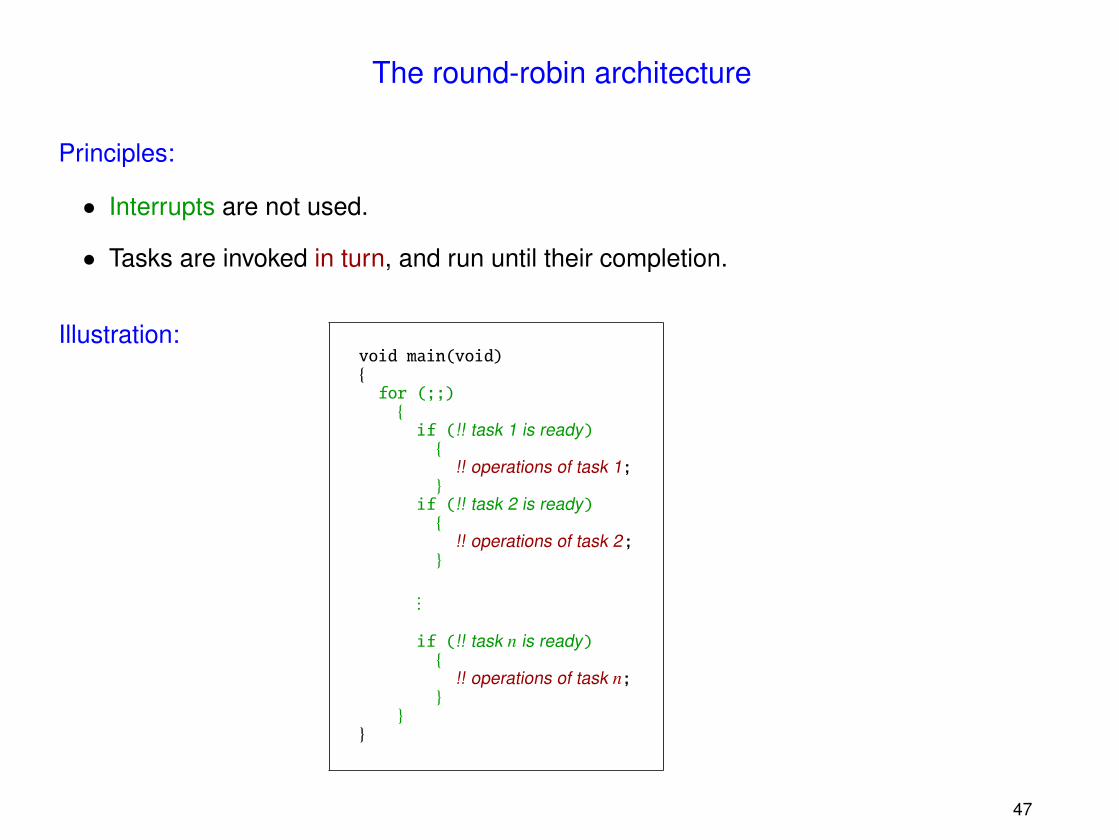
The round-robin architecture
Principles:
• Interrupts are not used.
• Tasks are invoked in turn, and run until their completion.
Illustration:void main(void){for (;;){if (!! task 1 is ready){
!! operations of task 1;}
if (!! task 2 is ready){
!! operations of task 2;}
...
if (!! task n is ready){
!! operations of task n;}
}}
47
Advantages:
• Simple solution, but sufficient for some applications.
• Exchanging data between tasks is easy.
Drawbacks:
• The worst-case latency of an external request is equal to the execution time of theentire main loop.
• Implementing additional features can adversely affect the correctness of a system, byincreasing latencies beyond acceptable bounds.
48
Example (multimeter):#include "types.h"#include "multimeter.h"
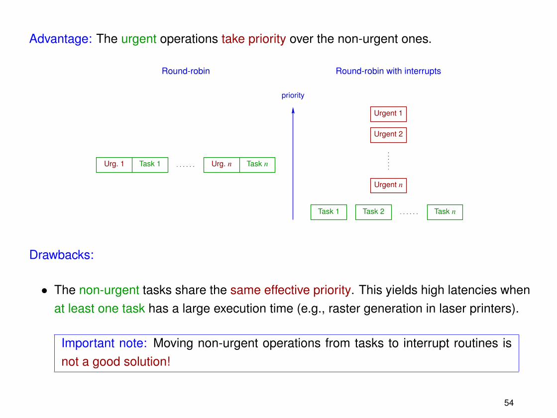
Advantage: The urgent operations take priority over the non-urgent ones.
Round-robin Round-robin with interrupts
priority
Urg. 1 Urg. n
Urgent 1
Urgent 2
Urgent n
Task 1 Task n
Task 1 Task 2 Task n
Drawbacks:
• The non-urgent tasks share the same effective priority. This yields high latencies whenat least one task has a large execution time (e.g., raster generation in laser printers).
Important note: Moving non-urgent operations from tasks to interrupt routines isnot a good solution!
54
Indeed,
– performing non-urgent operations in an interrupt routine increases the latency ofinterrupts with a lower or equal priority;
– interrupts do not offer flexible synchronization mechanisms.
• Data exchange operations between interrupt routines and tasks have to be correctlyimplemented (cf. Chapter 3).
55
Example: Serial filter
The goal is to develop a two-way filter connecting two serial lines.
CPUUART UART
Principles:
• Incoming bytes are signaled by interrupt requests, which must be answered as soonas possible (before the next received byte).
• When a UART is ready to send a byte on its output line, it requests an interrupt. Theprocessor is then free to wait for an arbitrarily long time before providing this byte.
!! initialize global data;!! initialize interrupt vectors;
enable();
for (;;){if (fifo_content_size(rx1) >= FILTER_THRESHOLD){
!! remove data from rx1;!! filter;!! add the result to tx2;
}
if (fifo_content_size(rx2) >= FILTER_THRESHOLD){
!! remove data from rx2;!! filter;!! add the result to tx1;
}
if (uart1_ready && !fifo_is_empty(tx1)){char byte;
byte = fifo_get(tx1);disable();!! send byte to UART1;uart1_ready = 0;enable();
}
58
if (uart2_ready && !fifo_is_empty(tx2)){char byte;
byte = fifo_get(tx2);disable();!! send byte to UART2;uart2_ready = 0;enable();
}}
}
Notes:
• Attempting to add data to a saturated FIFO buffer cannot be a blocking operation (i.e.,it must instead discard data).
59
• The functions for handling FIFO buffers must execute correctly both in the interruptroutines and in the main code.
Example of implementation:
void fifo_put(fifo q, char c){BOOL intr_enabled;
...
intr_enabled = disable();
!! critical section;
if (intr_enabled)enable();
...}
60
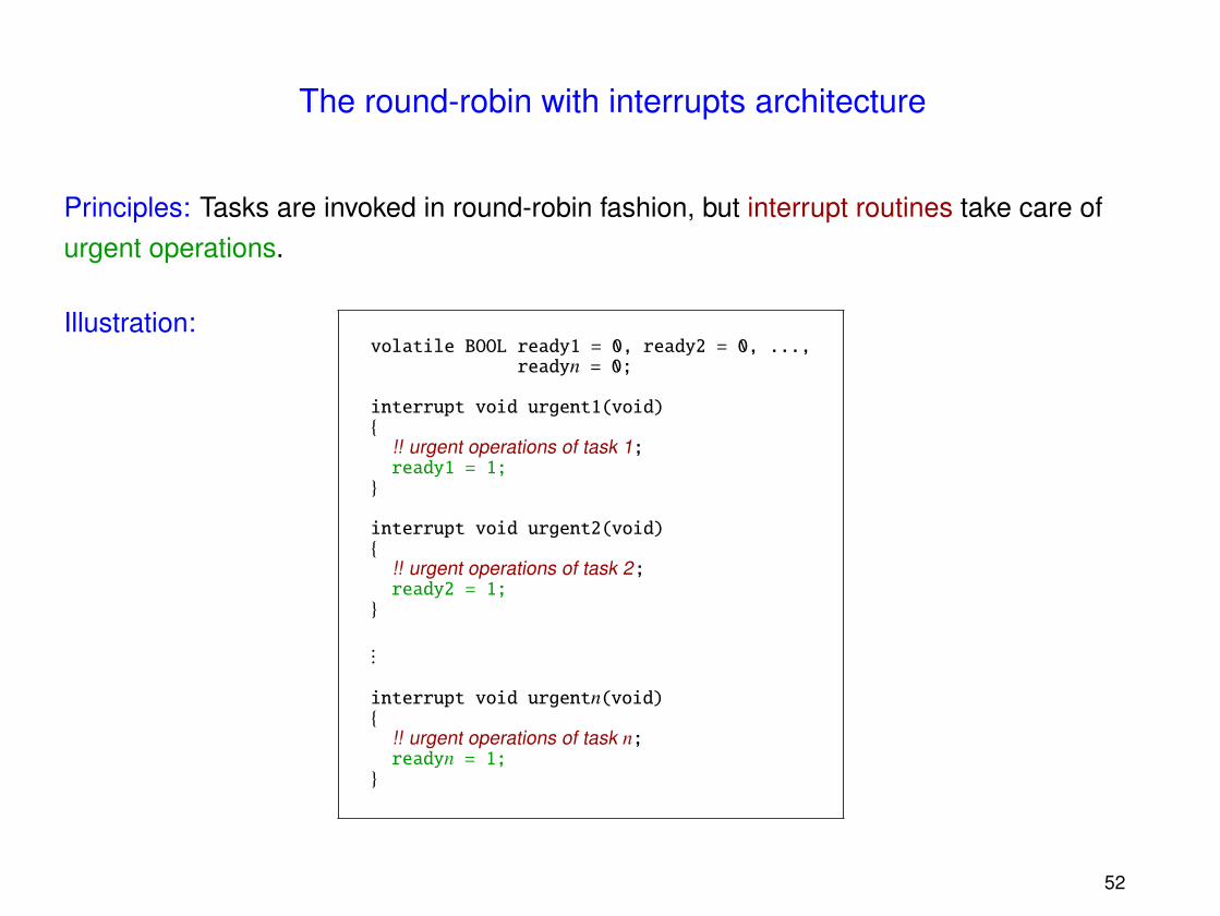
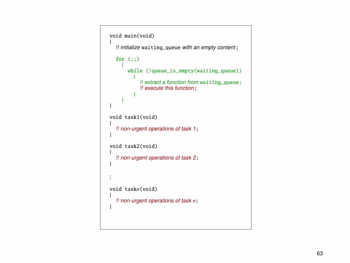
The waiting-queue architecture
Principles:
• In the same way as the round-robin with interrupts architecture, the operations arepartitioned into urgent and non-urgent tasks.
• Interrupt routines perform urgent operations, and then place in a waiting queuerequests for executing non-urgent tasks.
• The main program retrieves execution requests from the queue and calls thecorresponding functions. These requests are not necessarily processed in FIFO order.(For instance, different selection priorities can be assigned to non-urgent tasks.)
61
Illustration:#include "queue.h"
static volatile queue waiting_queue;
interrupt void urgent1(void){
!! urgent operations of task 1;!! add task1 to waiting_queue;
}
interrupt void urgent2(void){
!! urgent operations of task 2;!! add task2 to waiting_queue;
}
...
interrupt void urgentn(void){
!! urgent operations of task n;!! add taskn to waiting_queue;
}
62
void main(void){
!! initialize waiting_queue with an empty content;
for (;;){while (!queue_is_empty(waiting_queue)){
!! extract a function from waiting_queue;!! execute this function;
}}
}
void task1(void){
!! non-urgent operations of task 1;}
void task2(void){
!! non-urgent operations of task 2;}
...
void taskn(void){
!! non-urgent operations of task n;}
63
Advantage: The latency of a non-urgent high-priority task can become smaller than theexecution time of all the non-urgent operations.
Drawbacks:
• The maximum latency of a non-urgent task is still at least as large as the executiontime of the slowest task.
• Implementing the waiting-queue data structure can be tricky.
Example of application: A system monitors an industrial process by receiving data from anarray of sensors, processing this data, and displaying summarized results.
With the queue architecture, it is possible to ensure that the values produced by criticalsensors are always taken into account, even in the case of data saturation caused by amalfunctioning low-priority sensor.
64
The real-time operating system architecture
Principles:
• Urgent operations are performed by interrupt routines. Those are able to signal toother tasks that non-urgent operations are ready to be carried out.
• The non-urgent tasks are invoked dynamically rather than in a predefined order. Theresponsibility of calling tasks is assigned to the operating system, implemented as anadditional software component.
• The operating system is able to suspend the execution of a task before its completion,in order to transfer the processor to another task.
• The signals exchanged between tasks are handled by the operating system, instead ofbeing implemented with shared variables.
65
Illustration: #include "signal.h"
interrupt void urgent1(void){
!! urgent operations of task 1;!! send signal 1;
}
interrupt void urgent2(void){
!! urgent operations of task 2;!! send signal 2;
}
...
void task1(void){
!! wait for signal 1;!! non-urgent operations of task 1;
}
void task2(void){
!! wait for signal 2;!! non-urgent operations of task 2;
}
...
void main(void){
!! initialize the operating system;!! create and enable tasks;!! start task sequencing;
}
66
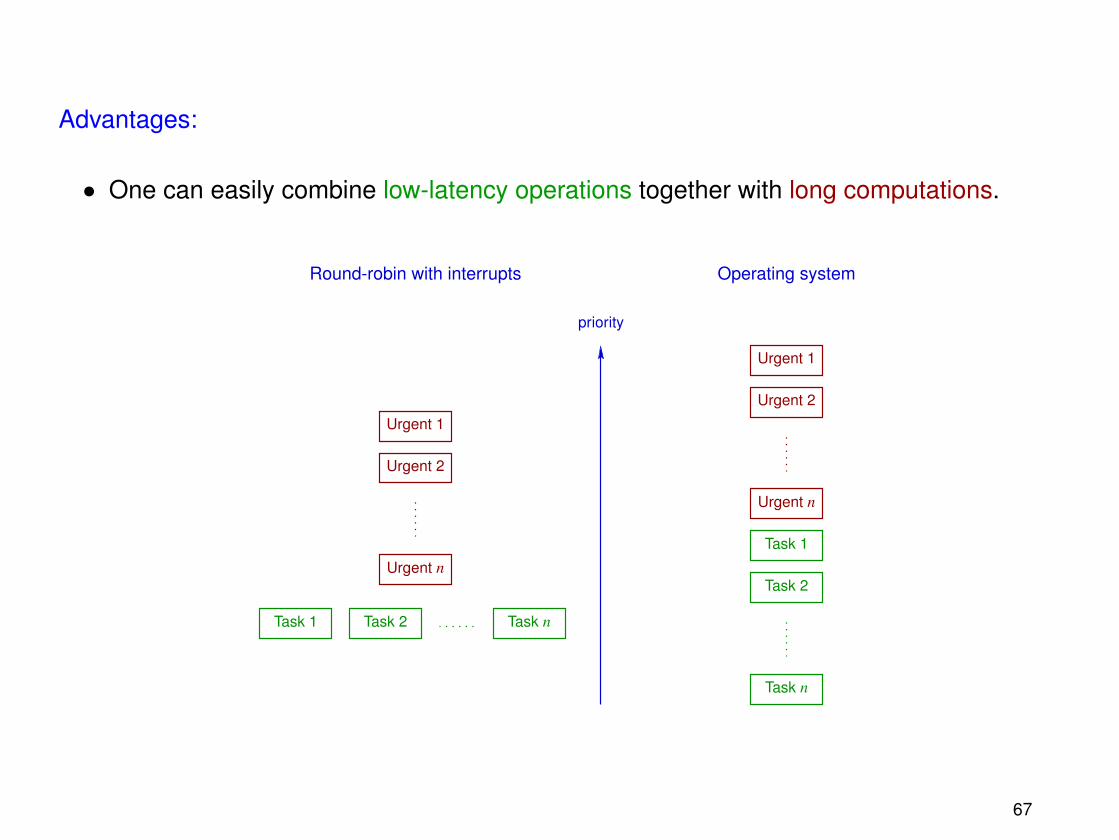
Advantages:
• One can easily combine low-latency operations together with long computations.
Urgent 1
Urgent 2
Urgent n
Task 1
priority
Round-robin with interrupts Operating system
Task 1 Task 2 Task n
Urgent n
Urgent 2
Urgent 1
Task 2
Task n
67
• The system is efficient: When a non-urgent task is waiting for a signal, the processorremains available for other computations.
• The structure of the system is robust: New features can easily be added withoutaffecting the latencies of urgent operations or of high-priority tasks.
• Operating systems tailored to embedded applications are commercially available.
68
Drawbacks:
• The system is complex (but this complexity is mainly located in the operating system,which can be reused over many projects).
• Data exchange operations have to be coordinated between a task and an interruptroutine, but also between tasks.
• The operating system consumes some amount of system resources (a typical figure is2 to 4 % of the instructions executed by the processor).
69
Summary
Task priorities and latencies:
Architecture Available priorities Maximum latency
round-robin none total execution timeof all tasks
round-robin interrupt routines; total execution timewith all tasks share the of all tasksinterrupts same priority + interrupt routines
waiting queue interrupt routines, execution time ofthen tasks the longest task
+ interrupt routines
operating interrupt routines, execution time ofsystem then tasks interrupt routines
70
Robustness and simplicity:
Architecture Robustness against Complexitymodifications
round-robin poor very simple
round-robin good for interrupt must handle data exchangeswith routines, poor for between tasks and interruptinterrupts the tasks routines
waiting queue fair must handle data exchanges,and implement the waitingqueue
operating very good quite complexsystem
71
Chapter 5
Real-time operating systems
72
Introduction
An operating system (OS) is a software component responsible for coordinating theconcurrent execution of several tasks, by
• managing the system resources (processor, memory, access to peripherals, . . . );
An OS is implemented by a kernel (an autonomous program), together with a library offunctions for accessing conveniently its services.
The real-time operating systems (RTOS) are operating systems specifically suited forembedded applications:
• They are usable on hardware with limited resources.
73
• The following features are precisely documented:
– the scheduling strategy,
– the maximum execution time of each service,
– every internal mechanism that can influence the latencies (e.g., the longest intervalduring which interrupts are disabled by the kernel).
• The user can implement urgent operations as interrupt routines.
• The OS provides time-oriented services: one-shot or periodic timers, periodicexecution of tasks, . . .
• Complex protection mechanisms against invalid user code may be absent.
• The kernel configuration can be parameterized in detail by the programmer.
74
Execution levels
At a given time, the instruction currently executed by the processor can either be
• a kernel operation (possibly located in an interrupt routine),
• an instruction belonging to an interrupt routine programmed by the user, or
• an instruction of a user task.
75
The processes
Each task managed by an OS is represented by a process. At a given time, a process is inone out of five possible states:
• Dormant: The task is not scheduled (e.g., because it is not yet known to the OS).
• Executable: The task is ready to execute instructions, but is not currently running.
• Active: The instructions of the task are now being executed by the processor.
• Blocked: The execution of the task is suspended while waiting for a signal, or for aresource to become available.
• Interrupted: The task is executing an interrupt routine programmed by the user.
76
Possible transitions between the states of a process:
Dormant
Blocked
Executable Active
Interrupted
77
The scheduler
The scheduler is the kernel component responsible for managing the state of theprocesses, i.e., for assigning the processor to the processes.
Principles:
• Each task is characterized by a priority (either constant or variable during itsexecution).
• The scheduler always assigns the processor to the non-dormant and non-blocked taskthat has the highest priority.
If several tasks share the highest priority, then the conflict can be solved in several ways:
• The time slicing approach consists in assigning the processor in turn to each of thesetasks, in order to execute a bounded sequence of instructions.
78
• One can alternatively assign the processor to a task that has been arbitrarily chosen.
• Another solution is to forbid different tasks to share the same priority.
Note: With the first two strategies, computing the deadline of a task becomes difficult. Mostreal-time operating systems thus implement the third solution.
79
Preemption
If a task T2 has a higher priority than the active task T1 and switches from the blocked tothe executable state, then there are two possible scheduling strategies:
• The task T2 remains suspended (in executable state) until completion of T1. Thescheduler is said to be non-preemptive.
t
The resource expected byT2 becomes available
T1
routineInterrupt
T2
80
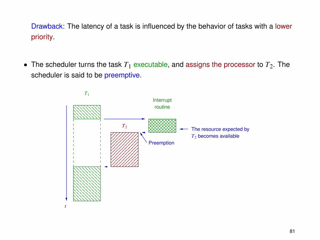
Drawback: The latency of a task is influenced by the behavior of tasks with a lowerpriority.
• The scheduler turns the task T1 executable, and assigns the processor to T2. Thescheduler is said to be preemptive.
T2
t
The resource expected byT2 becomes available
T1
routineInterrupt
Preemption
81
Context switching
The scheduler performs a context switch when it transfers the processor from a process toanother.
Principles:
• The suspended task must be able to resume its execution later. The state of theprocessor thus has to be saved when the task is suspended.
The kernel memory maintains for each non-dormant process a context storage areafor this purpose.
82
Illustration:
T1
T1
T2
T2
t...
Kernel
83
• The working data of the suspended task has to be preserved until its execution can beresumed.
This data is located on the runtime stack of the task, which contains
– the context (return address, stack register values) of the active function calls, and
– the arguments and local variables of these function calls.
84
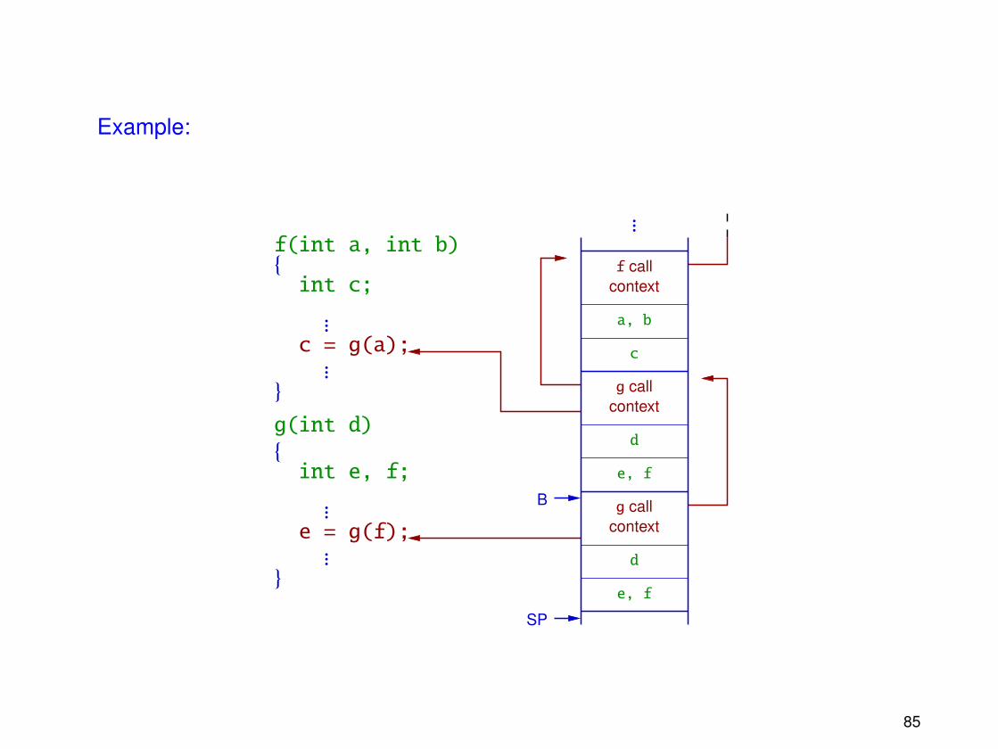
Example:
c = g(a);
e = g(f); contextg call
contextg call
contextf call
a, b
c
f(int a, int b)
int c;
g(int d)
int e, f;
d
e, f
d
e, f
{
...
...}
{
...
...}
...
B
SP
85
Notes:
– Since a task can be suspended at any time, it is necessary for each process tomanage its own stack.
– In general the stack pointers (e.g., top of stack, base of current stack frame) areparticular processor registers. Those pointers are therefore saved, together withthe other registers, during a context switch.
– The kernel also manages its own stack.
86
Reentrancy
With a preemptive scheduler, calling the same function in different tasks can beproblematic.
Example:
aux
x1
y1
x2
y2
1
2
2
3 y1← 2
swap(&x1, &y1)
aux← 1
x1← 2
swap(&x2, &y2)
aux← 2
x2← 3
y2← 2
void swap(int *p1, int *p2){aux = *p1;
static int aux;
*p1 = *p2;*p2 = aux;
}
87
Definition: A function is said to be reentrant if it can be simultaneously called by severaltasks without possibility of conflict.
Examples:
• Reentrant function:void swap(int *p1, int *p2){int aux;
aux = *p1;*p1 = *p2;*p2 = aux;
}
• Non-reentrant function:
volatile int is_new; /* modified by another task */
Note: The second function is non-reentrant for three reasons:
– The test and assignment operations over the global variable is_new are performedby different instructions.
– The operations involving is_new are not necessarily atomic.
– The function printf might not be reentrant.
89
Communication between tasks
Organizing data transfers between processes is more difficult than between tasks andinterrupt routines:
• Context switches can occur unpredictably at any time.
• Context switches can only be disabled in software, by modifying the scheduling policy.
Solution: One can use services provided by the kernel, aimed at
• synchronizing the operations of concurrent tasks, and
• coordinating data transfers from a process to another.
Note: Using incorrectly communication or synchronization services can lead to deadlocks,when every task is suspended waiting for resources that can only be provided by othertasks.
90
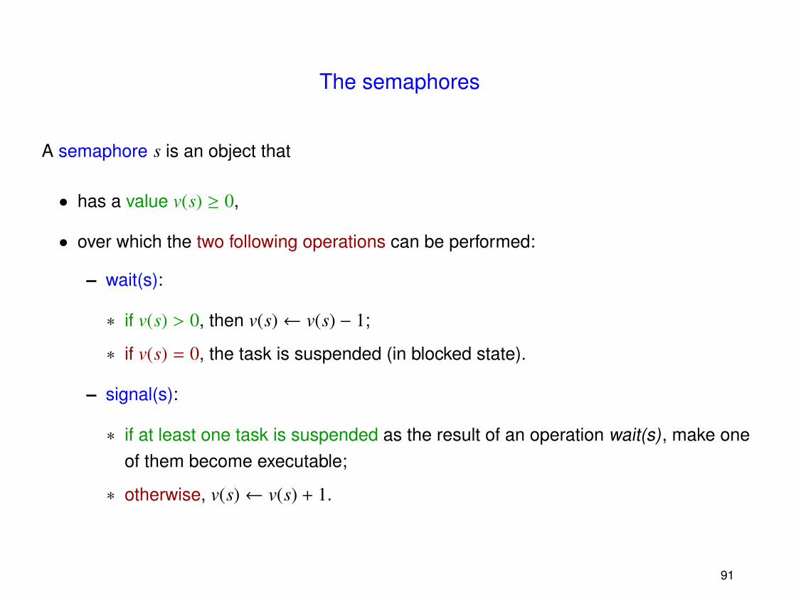
The semaphores
A semaphore s is an object that
• has a value v(s) ≥ 0,
• over which the two following operations can be performed:
– wait(s):
∗ if v(s) > 0, then v(s)← v(s) − 1;
∗ if v(s) = 0, the task is suspended (in blocked state).
– signal(s):
∗ if at least one task is suspended as the result of an operation wait(s), make oneof them become executable;
∗ otherwise, v(s)← v(s) + 1.
91
Notes:
• The operations that test and modify the value of a semaphore must be implementedatomically.
• Binary semaphores are semaphores with a value restricted to the set {0, 1}.
• There are several possible strategies for selecting a task blocked on a semaphore inorder to make it executable again: arbitrary choice, FIFO policy, priorities, . . .
In most applications, acquiring a semaphore represents the access right to a resource.
Example: Mutual exclusion between two tasks (binary semaphore s initialized to 1).
void task1(void){for (;;){wait(s);!! critical section;signal(s);!! other operations;
}}
void task2(void){for (;;){wait(s);!! critical section;signal(s);!! other operations;
}}
92
The message queues
A message queue is an object that implements synchronous or asynchronous datatransfers between tasks.
Principles:
• The maximum capacity of a queue (i.e., the maximum number of messages that havebeen written and not yet read) and the size of each message are fixed.
• Send and receive operations are performed atomically.
• A task that is waiting to receive data from a queue is suspended by the scheduler (inblocked state).
Variants:
• Several data access policies are possible: FIFO order, arbitrary selection, prioritymechanism.
93
• Sending data to a saturated message queue can either discard the new message,block the sender, block the sender during a bounded amount of time, . . .
• When a task is blocked waiting for data from an empty queue, a maximum suspensiondelay (i.e., a timeout) can be specified.
• The maximum capacity of a queue can be reduced to zero (rendez-voussynchronization).
94
Programming with interrupts
The scheduler and the interrupt mechanism are both able to move the control point fromone location in the program code to another. One must take care of avoiding conflictsbetween those mechanisms.
First rule:
An interrupt routine is not allowed to call an OS service if this service cansuspend the current task (e.g., acquiring a semaphore (wait), receiving data froma message queue, . . . ).
95
• Indeed, if this rule is not respected, then an interrupt routine can get suspended, whichamounts to assigning to this interrupt routine an effective priority smaller than the oneof a task.
Example:
T2
Interruptroutine
T1
T3
t
T1 is resumed
End of interrupt
T1 becomes active
T1 is suspended
96
• Moreover, the interrupt routine might get called again before its completion. If thisroutine is not reentrant, then erroneous behaviors are possible (e.g., overwriting asaved processor context).
T1
routineInterrupt
T2
t
T1 is suspended
Reentrant call
End of interrupt
End of interrupt
T1 is resumed
97
Second rule:
If an interrupt routine calls an OS service that can lead to a context switch, thenthe scheduler must be informed that this service call is performed inside aninterrupt routine.
If this rule is not respected, then the scheduler can suspend the execution of an interruptroutine.
Example:
t
End of interrupt
T1 is preempted
T1
routineInterrupt
T2
98
Solution: At the beginning and at the end of each interrupt routine programmed by theuser, special OS services must be called in order to inform the kernel that the processor iscurrently executing an interrupt routine.
Notes:
• In the case of many levels (i.e., priorities) of interrupts, those services must handlecorrectly nested interrupt routine calls.
• Some operating systems provide alternate versions of some services, intended to becalled from interrupt routines.
• Interrupt latencies are increased by the time needed for executing the notificationservices.
99
Example:
T2
Kernel
T1 Interruptroutine
tEnd of interrupt
T1 is preempted
Interrupt leaving service
Context switch
Possible preemption
Service call
Interrupt entering service
Interrupt request
100
Note: An interrupt routine containing explicit instructions for saving the processor statemust perform the corresponding restore operations before informing the kernel that theinterrupt routine is about to end.
101
Time-oriented services
The real-time operating systems offer timed services, for instance for suspending a task fora predefined amount of time.
Principles:
• A dedicated component triggers periodic requests (clock, heartbeat) for an interruptthat has
– a higher priority than the interrupts programmed by the user, and
– an interrupt routine implemented by the kernel.
• The delay during which a task is suspended is expressed in the number ofoccurrences of this interrupt request signal (ticks, beats).
102
Note: The precision is limited. Asking to suspend the task during k ticks only ensures thatthe suspension delay is greater or equal to k − 1 times the clock period.
Example:
delay(1) delay(1)
Periodic interrupt
Higher-priority tasks
Periodic interrupt routine
Timed task
103
Chapter 6
Real-time operating systems:Implementation issues
104
Overview of the main problems
• The following operations need to be efficient (i.e., ideally, to have a maximum executiontime that is independent from the number of tasks managed by the operating system):
– Identifying the executable process with the highest priority in order to make itactive.
– Performing a context switch.
– Selecting the process that has to be unblocked following an operation over acommunication object.
• For operations over communication or synchronization objects that can suspend aprocess, it should be possible to specify a timeout (i.e., a maximum suspension delay).
• One needs to be able to access all processor registers.
• For some applications, the real-time operating system has to share the processor withanother operating system.
105
Task control blocks
A Task Control Block (TCB) is a data structure that represents a non-dormant processinside the kernel memory. This structure contains:
• The current priority of the task.
Note: When the task priorities are fixed and unique, they can also be used as processidentifiers.
• The context of the task, i.e., the state of the processor, saved when the task was lastsuspended.
Notes:
– This context contains, in particular, a pointer to the runtime stack of the process.
– Some operating systems (e.g., µCOS-III) save the bulk of the context on this stack.
• The current state of the process (executable, active, blocked, or interrupted).
106
• Information for managing a potential timeout.
• A pointer to a data structure representing a communication object that the task is(possibly) attempting to acquire.
• Pointers linking the TCB to the global data structures of the kernel.
• Auxiliary data aimed at speeding up some operations (e.g., values derived from thetask priority).
• Additional information managed by the user (e.g., configuration data for a peripheralcontrolled by the task).
107
Global data structures of the kernel
The global information managed by the kernel essentially contains:
• Sets of task control blocks corresponding to
– the executable (or active) processes,
– the processes suspended for a given delay,
– the free blocks.
Those sets are organized as simply or doubly-linked lists, or by hash tables, in order tobe able to manipulate them in constant time.
• A structure for identifying efficiently the executable process with the highest priority.
• An index for accessing directly a task control block from its corresponding processidentifier.
• Data structures representing the state of communication objects.
108
Example: µCOS-III
• The maximum number of process priorities is a compile-time configuration parameterof the kernel (OS_CFG_PRIO_MAX).
• The set of executable processes is represented by
– an array OSPrioTb[] of bit fields (with a width suited for the processorarchitecture). Each set bit corresponds to a priority for which there exists at leastone executable (or active) process.
– an array OSRdyList[] associating to each priority level a doubly-linked list of TCBof executable processes.
Note: µCOS-III allows several processes to share the same priority. Suchprocesses are then scheduled by time slicing.
– A pointer OSTCBCurPtr to the TCB of the currently active task.
• The set of processes suspended for some delay is represented by a hash tableOSCfg_TickWheel[], indexed by their deadline.
109
• Keeping an index of all non-dormant tasks is not necessary, because processidentifiers are defined as pointers to the corresponding TCB.
• Managing a list of free TCB is avoided by letting the user code allocate TCB whentasks are created.
• A global counter OSIntNestingCtr keeps tack of the current interrupt nesting level.
110
Illustration (32-bit processor)
012
14
42
OS TCB(task 42)
OS TCB(task 14-2)
stack of task 14-1 stack of task 14-2 stack of task 42
0
0
0
0
0
0
0
0
0
0
0
0
0
0
0
0
0
0
0
0
0
0
0
0
0
0
0
0
0
0
0
0
0
0
1
0
0
0
0
0
0
0
0
1
0
0
0
0
0
0
0
0
0
0
0
0
0
0
0
0
0
0
0
0
31 0
OSRdyList[]
14 14 42
OS TCB(task 14-1)
0
1
OSPrioTb[]
OSTCBCurPtr
111
Note: Identifying quickly the executable process with the highest priority is achieved by
• exploiting specific processor instructions (e.g., Count Leading Zeros, CLZ), or
• tabulating the possible values of bit fields.
112
The scheduler
The scheduler is implemented by a kernel function called after each operation that canpotentially influence the state of processes:
• Creating or destroying a task, or modifying a task priority.
• Acquiring or releasing a communication object.
• Servicing the clock interrupt.
This function must be kept simple and efficient, and only performs the following operations:
1. Checking whether the scheduler is allowed to preempt tasks.
2. Identifying the executable task with the highest priority.
3. Performing a context switch in order to assign the processor to this task.
113
Note: The possibility of enabling or disabling preemption is offered because
• preempting the current task should be prevented inside interrupt routines (cf.Chapter 5).
• it provides a simple mechanism for manipulating atomically shared variables orcommunication objects (preemption locks). However, this mechanism
– increases the latency of the tasks (by the duration of the longest interval duringwhich preemption is disabled), and
– affects all the tasks of the system (not only those that need to be coordinated).
114
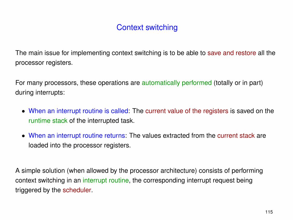
Context switching
The main issue for implementing context switching is to be able to save and restore all theprocessor registers.
For many processors, these operations are automatically performed (totally or in part)during interrupts:
• When an interrupt routine is called: The current value of the registers is saved on theruntime stack of the interrupted task.
• When an interrupt routine returns: The values extracted from the current stack areloaded into the processor registers.
A simple solution (when allowed by the processor architecture) consists of performingcontext switching in an interrupt routine, the corresponding interrupt request beingtriggered by the scheduler.
115
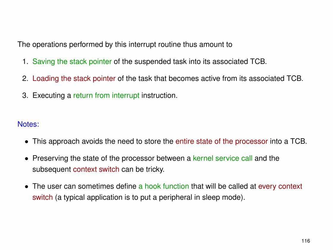
The operations performed by this interrupt routine thus amount to
1. Saving the stack pointer of the suspended task into its associated TCB.
2. Loading the stack pointer of the task that becomes active from its associated TCB.
3. Executing a return from interrupt instruction.
Notes:
• This approach avoids the need to store the entire state of the processor into a TCB.
• Preserving the state of the processor between a kernel service call and thesubsequent context switch can be tricky.
• The user can sometimes define a hook function that will be called at every contextswitch (a typical application is to put a peripheral in sleep mode).
116
Task creation and destruction
Creating or destroying a process essentially amounts to updating the data structuresmanaged by the kernel, and to then call the scheduler.
Notes:
• The runtime stack of a new process is allocated by the task that asks this process tobe created.
• The initial processor context of a new task, including its entry point, is built when itsstack is initialized.
• A parameter can generally be passed to a newly created task, in order to make itpossible for several tasks sharing the same code to behave differently.
• One must take care of removing references to a task that is destroyed from thestructures managing communication objects.
117
The idle task(s)
Some operating systems systematically create one or many internal tasks, with a lowerpriority than the processes instantiated by the user.
There are many advantages to this approach:
• The scheduler can be more efficient, since it does not has to check whether thereexists at least one executable task.
• Such tasks make it possible to measure the processor utilization.
Example: µCOS-III defines two idle tasks:
– OS_IdleTask(), executing an infinite loop incrementing global counters.
– OS_StatTask() (optional), computing at regular intervals the processor utilizationfrom the value of the counters.
• In the case of a mobile system, an idle task can put the processor and someperipherals in sleep mode in order to conserve energy.
118
Time management
Quantitative time management is performed by the clock interrupt routine.
Principles: At each clock tick:
• One computes the set of suspended tasks that must become executable again.
• One increments a counter aimed at measuring elapsed time.
Notes:
• The maximum execution time of the clock interrupt routine depends on the mechanismused for waking up tasks.
With the help of suitable data structures, this time can become equal to the number oftasks becoming executable.
• It is often necessary to configure and calibrate the clock interrupt source duringinitialization.
119
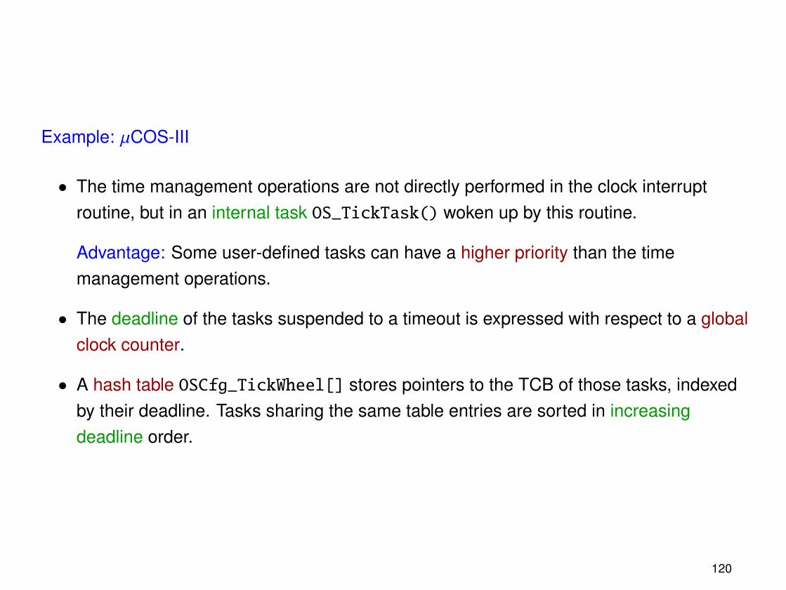
Example: µCOS-III
• The time management operations are not directly performed in the clock interruptroutine, but in an internal task OS_TickTask() woken up by this routine.
Advantage: Some user-defined tasks can have a higher priority than the timemanagement operations.
• The deadline of the tasks suspended to a timeout is expressed with respect to a globalclock counter.
• A hash table OSCfg_TickWheel[] stores pointers to the TCB of those tasks, indexedby their deadline. Tasks sharing the same table entries are sorted in increasingdeadline order.
120
Communication and synchronization objects
In the kernel memory, a communication or synchronization object is represented by astructure containing:
• The type of the object (semaphore, message queue, . . . ).
• Data representing the state of the object (e.g., for a semaphore, an integer counter).
• A set of suspended tasks, waiting to acquire the object.
In the case of a priority-based selection policy, such a set can be represented by adoubly-linked list of TCB, sorted in decreasing priority order.
If necessary, the kernel also maintains a table of allocated objects.
Finally, the TCB of each task waiting for an object contains a pointer to the structuremanaging this object.
Note: Implementing kernel services that update the state of objects does not requirespecific instructions such as test and set, since it is sufficient to disable interrupts duringnon-atomic operations.
121
Combining a real-time and a non-real-time operating systems
It is possible to combine in a single application a real-time operating system (RTOS) withanother operating system (host OS). There are two possibilities:
• The operations of the host operating system are suspended when the real-time OS isstarted, and get the processor back when the RTOS terminates (e.g., µCOS-III).
• The host operating system is seen as special task that has a lower priority than all thetasks managed by the real-time OS (e.g., RTAI).
For implementing this approach, it is necessary to ensure that the host OS can neverdisable the interrupts managed by the kernel or the real-time tasks.
122
Chapter 7
Scheduling problems
123
Priority inversion
Priority inversion happens when a task is suspended waiting for a resource controlled byanother task with a lower priority.
Example:
t
T1 is preempted
T2 is preempted
T3 is suspended
T2 terminates
T1
T3
T2
T3 is resumed
wait(s)
wait(s)
signal(s)
124
Problem:
In such a situation, the effective priority of T3 becomes equal to the one of T1.
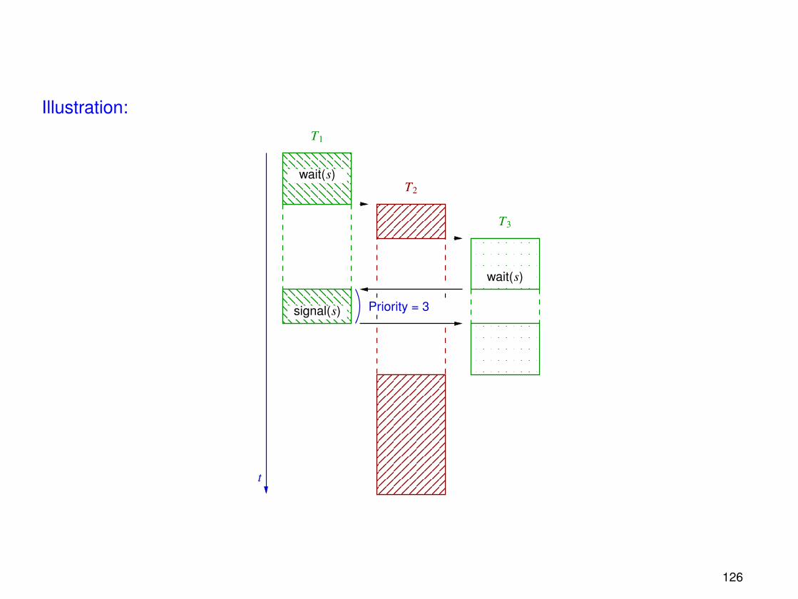
Solution:
The priority of T1 can be momentarily increased (becoming equal to that of T3) during allthe time that T3 is suspended waiting for the semaphore acquired by T1.
This priority inheritance mechanism is automatically applied by some operating systems.
125
Illustration:
T2
T1
T3
Priority = 3
t
wait(s)
wait(s)
signal(s)
126
Periodic tasks scheduling
We consider a simplified programming environment satisfying the following hypotheses:
• The number of tasks to be executed is fixed.
• Each task is characterized by a distinct and constant priority.
• The execution requests for each task occur periodically, i.e., with a constant delaybetween two successive requests.
In particular, the timing of execution requests for a task cannot depend on operationsperformed by other tasks.
• The execution time of each task is constant.
127
• The following real-time constraint must be satisfied:
Each execution of a task must finish before or at the same time as the nextrequest for executing this task.
• Context switches are instantaneous and preemptive.
128
Critical instants and critical zones
In addition to its priority, each task τi is characterized by
• its period Ti, and
• its execution time (for each period) Ci.
Definitions:
• The response time of an execution request for τi is the delay between this request andthe end of the corresponding execution of this task.
• A critical instant for the task τi is an occurrence of an execution request for τi thatleads to the largest possible response time for this task.
• A critical zone for τi is an interval of duration Ti that starts at a critical instant (for τi).
129
Theorem 1: A critical instant for τi occurs when an execution request for this task coincideswith requests for executing all the tasks that have a higher priority than τi.
Proof: Assume that an execution request for τi occurs at t = t1, and that an executionrequest for a higher-priority task τ j is received at t = t2.
tt1 t1 + Ti
Ti
t2 t2 + C j t2 + T j
Advancing the request for τ j from t2 to t1 can never decrease the response time of τi
The same reasoning can be applied to all the tasks that have a higher priority than τi.
130
Schedulable tasks
Definition: A set of tasks is schedulable (with respect to a given assignment of priorities) ifthe response time of each task τi is always less than or equal to its period Ti.
Thanks to Theorem 1, checking whether a given set of tasks is schedulable reduces tosimulating the scheduling strategy in the particular case of simultaneous executionrequests for all tasks at t = 0.
Examples: Consider two tasks τ1 and τ2, with T1 = 2, T2 = 5, C1 = 1 and C2 = 1.
• If τ1 has a higher priority than τ2.
0 1 2 3 4 5
0 1 2 3 4 5
t
t
Critical zone
τ2
τ1
131
The tasks are schedulable, and remain schedulable even if the execution time of τ2 isincreased by one time unit (C2 = 2):
0 1 2 3 4 5
0 1 2 3 4 5
Critical zone
t
tτ1
τ2
• If τ2 has a higher priority than τ1.
0 1 2 3 4 5
0 1 2 3 4 5
Critical zone
τ1
τ2
t
t
The tasks are schedulable.
Note: In this case, the execution time of τ1 and τ2 cannot be increased anymore.
132
Rate-Monotonic Scheduling
In the previous example, the best strategy was to assign the highest priority to the task thathas the smallest period.
Definition: Given a set of tasks τ1, τ2, . . . , τn with respective periods T1,T2, . . . ,Tn, theRate-Monotonic Scheduling (RMS) strategy consists in assigning distinct prioritiesP1, P2, . . . Pn to the tasks, such that for all i, j:
Ti < T j ⇒ Pi > P j.
The following result establishes that the RMS strategy is optimal:
Theorem 2: If a set of tasks is schedulable with respect to some priorities assignment, thenit is schedulable as well with respect to priorities defined by the RMS strategy.
133
Proof: Consider a set of tasks τ1, τ2, . . . , τn for which there exists a priorities assignmentP1, P2, . . . Pn that makes them schedulable.
Let τi and τ j two tasks with adjacent priorities Pi and P j, such that Pi > P j.
If Ti > T j, then the priorities of τi and τ j can be swapped:
τi
τi
τ j
τ j
T j Ti
t
0
The resulting set of tasks remains schedulable.
By performing repeatedly this operation, one eventually obtains a priorities assignmentcorresponding to the RMS strategy.
134
The processor load factor
Consider a set of tasks τ1, τ2, . . . , τn with respective periods and execution timesT1,T2, . . . ,Tn and C1,C2, . . . ,Cn.
The processor load factor U corresponding to this set of tasks represents the relativeamount of CPU time needed for executing them:
U =
n∑i=1
CiTi.
Definition: A set of tasks fully uses the processor if
• this set of tasks is schedulable, and
• any increase of the execution time of a task (and hence of the processor load factor)yields a set of tasks that is not schedulable anymore.
135
Notes:
• Thanks to Theorem 2, checking whether a set of tasks is schedulable or not can bedone by assigning RMS priorities to those tasks.
• A set of tasks that has a processor load factor less than 1 is not necessarilyschedulable:
Example:
τ1 : T1 = 5, C1 = 2τ2 : T2 = 7, C2 = 4
}U =
25
+47≈ 97%
t
t
0 1 2 3 4 5 6 7
0 1 2 3 4 5 6 7
τ1
τ2
136
Classifying sets of tasks
The set of sets of tasks can be partitioned into three classes:
• The non schedulable sets of tasks.
• The sets of tasks that fully use the processor.
• The schedulable sets of tasks that do not fully use the processor.
U
100%
0%
UL
Non schedulable sets of tasks
Sets of tasks that fullly use the CPU
Schedulable sets of tasks
137
The best lower bound UL on the processor load factor of the sets of tasks that fully use theprocessor is such that:
• If the processor load factor of a set of tasks is less than or equal to UL, then this set oftasks is schedulable (regardless of the periods and execution times of the tasks!).
• If the processor load factor of a set of tasks is greater than UL, then this set of tasksmay or may not be schedulable, depending on the details of the tasks.
138
UL: Case of two tasks
Let τ1 and τ2 be two tasks with respective periods and execution times T1,T2 and C1,C2.We assume T1 < T2. According to the RMS strategy, we assign a higher priority to τ1.
During a critical zone of τ2, the number of execution requests for τ1 is equal to⌈T2
T1
⌉.
• If all the executions of τ1 in the interval [0,T2] terminate earlier than or at t = T2.
C1 C1
T1
C2
T2
τ2
τ1
t
0
The following condition is satisfied:
C1 ≤ T2 − T1
⌊T2T1
⌋.
139
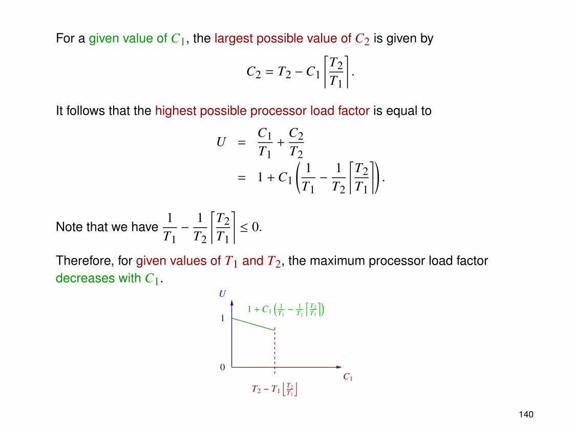
For a given value of C1, the largest possible value of C2 is given by
C2 = T2 −C1
⌈T2T1
⌉.
It follows that the highest possible processor load factor is equal to
U =C1T1
+C2T2
= 1 + C1
(1
T1−
1T2
⌈T2T1
⌉).
Note that we have1
T1−
1T2
⌈T2T1
⌉≤ 0.
Therefore, for given values of T1 and T2, the maximum processor load factordecreases with C1.
1 + C1
(1
T1− 1
T2
⌈T2T1
⌉)1
0
U
C1
T2 − T1
⌊T2T1
⌋140
• If an execution of τ1 is still unfinished at t = T2.
C2
C1 C1
τ2T2
τ1
0
t
T1
The following condition is satisfied:
C1 > T2 − T1
⌊T2T1
⌋.
For a given value of C1, the largest possible value of C2 is given by
C2 = (T1 −C1)⌊T2T1
⌋.
Hence, the highest possible processor load factor is equal to
U =T1T2
⌊T2T1
⌋+ C1
(1
T1−
1T2
⌊T2T1
⌋).
141
For given values of T1 and T2, this expression increases with C1, since
1T1−
1T2
⌊T2T1
⌋≥ 0.
1
T1T2
⌊T2T1
⌋+ C1
(1
T1− 1
T2
⌊T2T1
⌋)U
0T2 − T1
⌊T2T1
⌋T1 C1
142
Summary:
1
T1T2
⌊T2T1
⌋+ C1
(1
T1− 1
T2
⌊T2T1
⌋)U
0T2 − T1
⌊T2T1
⌋T1 C1
The smallest value of U corresponds to the boundary between the two cases, where wehave
C1 = T2 − T1
⌊T2T1
⌋.
By introducing this value in the expression of U, one obtains
U =T1T2
⌊T2T1
⌋+
(T2 − T1
⌊T2T1
⌋) (1
T1−
1T2
⌊T2T1
⌋)=
T1T2
⌊T2T1
⌋+
T2T1− 2
⌊T2T1
⌋+
T1T2
⌊T2T1
⌋2.
143
Let us define I =
⌊T2T1
⌋and f =
T2T1−
⌊T2T1
⌋.
The previous expression becomes
U =I
I + f+ (I + f ) − 2I +
I2
I + f
= 1 − f1 − fI + f
.
The smallest possible value of U is obtained with I = 1. We then have
U = 1 − f1 − f1 + f
,
and
dUd f
=f 2 + 2 f − 1
(1 + f )2 .
The best lower bound UL on U is thus obtained with I = 1 and f = −1 +√
2:
UL = 1 − (√
2 − 1)2 −
√2
√2
= 2(√
2 − 1) ≈ 0.83.
144
Case of two tasks: Conclusions
Theorem 3: If a set of two periodic tasks has a processor load factor that is less than orequal to 2(
√2 − 1), then this set of tasks is schedulable.
Notes:
• This sufficient criterion is independent from the periods and execution times of thetasks.
• In the particular case where T2 is an integer multiple of T1, one has f = 0, hence
UL = 1.
All pairs of tasks satisfying this condition (and such thatC1T1
+C2T2≤ 1 !) are thus
schedulable.
145
UL: Case of n tasks
The goal is now to compute the value of UL
• for a given number n of tasks, and
• for any number of tasks.
The first step is to establish an intermediate result:
Lemma 1: Let τ1, τ2, . . . , τn be periodic tasks with the respective periods and executiontimes T1,T2, . . . ,Tn and C1,C2, . . . ,Cn, such that
• This set of tasks fully uses the processor,
• 0 < T1 < T2 < · · · < Tn−1 < Tn < 2T1,
• The processor load factor of this set of tasks is minimum among all sets of tasks thatfully use the processor.
146
In this case, one has
C1 = T2 − T1,
C2 = T3 − T2,...
Cn−1 = Tn − Tn−1,
Cn = Tn − 2(C1 + C2 + · · ·Cn−1)
= 2T1 − Tn.
C1 C1
T1
Cn−1
Tn−1
C2
T2
C2
TnT3
CnCn−1
0
t
147
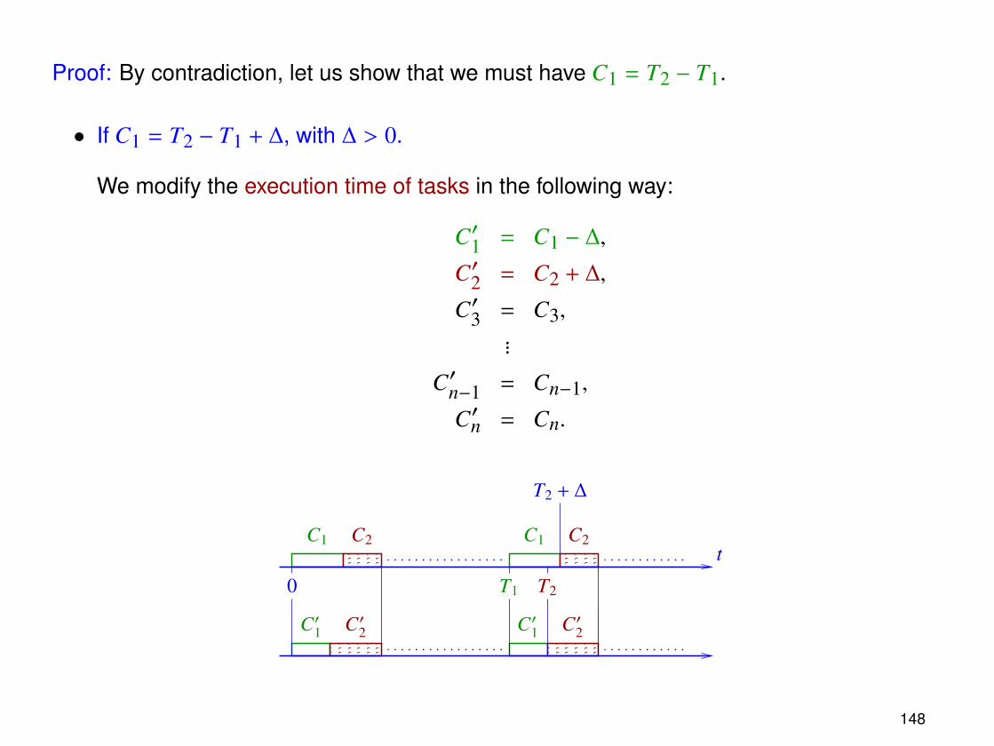
Proof: By contradiction, let us show that we must have C1 = T2 − T1.
• If C1 = T2 − T1 + ∆, with ∆ > 0.
We modify the execution time of tasks in the following way:
C′1 = C1 − ∆,
C′2 = C2 + ∆,
C′3 = C3,...
C′n−1 = Cn−1,
C′n = Cn.
C′2
C1
C′1 C′1
C1
T1
C2
T2
C′2
t
0
C2
T2 + ∆
148
After the modification, the new set of tasks still fully uses the processor. However, theprocessor load factor now becomes
U′ = U −∆
T1+
∆
T2< U,
which contradicts the hypothesis that U is minimum.
• If C1 = T2 − T1 − ∆, with ∆ > 0.
We now modify the execution time of tasks as follows:
C′′1 = C1 + ∆,
C′′2 = C2,
C′′3 = C3,...
C′′n−1 = Cn−1,
C′′n = Cn − 2∆.
149
C1
C′′1 C′′1
C2
C′′2 C′′2
τn τnC1 C2
τn
τnτn
∆ ∆ ∆ T1 T2
T2 − ∆
0
t
The resulting set of tasks fully uses the processor. The processor load factor becomes
U′ = U +∆
T1−
2∆
Tn.
Since we have by hypothesis Tn < 2T1, this property contradicts U′ < U.
By similar reasoning, one obtains successively
C2 = T3 − T2,
C3 = T4 − T3,...
Cn−1 = Tn − Tn−1.
150
Since the processor is fully used, one finally gets
Cn = Tn − 2(C1 + C2 + · · ·Cn−1).
Corollary: For each set of tasks that satisfies the hypotheses of Lemma 1, the processorload factor is equal to
U =T2 − T1
T1+
T3 − T2T2
+ · · · +Tn − Tn−1
Tn−1
+2T1 − Tn
Tn
=T2T1
+T3T2
+ · · · +Tn
Tn−1+ 2
T1Tn− n.
151
For each i = 1, 2, . . . , n − 1, let us define qi =Ti+1Ti
. We then have
U = q1 + q2 + · · · + qn−1 +2
q1q2 · · · qn−1− n,
and thus for each i,∂U∂qi
= 1 − 2q1q2 · · · qi−1qi+1 · · · qn−1
(q1q2 · · · qn−1)2 .
The best lower bound UL of U therefore corresponds to
∂U∂qi
= 0
1 −1qi.
2q1q2 · · · qn−1
= 0.
152
For each i, one has
qi =2
q1q2 · · · qn−1,
hence
q1 = q2 = · · · = qn−1 = 21n .
By introducing these values in the expression of U, one obtains
UL = (n − 1)21n +
2
2n−1
n− n
= (n − 1)21n + 2
1n − n
= n(21n − 1).
We thus have the following result:
Theorem 4: If the periods T1,T2, . . . ,Tn of a set of n tasks are such that
0 < T1 < T2 < · · · < Tn−1 < Tn < 2T1,
with a processor load factor that is less than or equal to n(21n − 1), then this set of tasks is
schedulable.
153
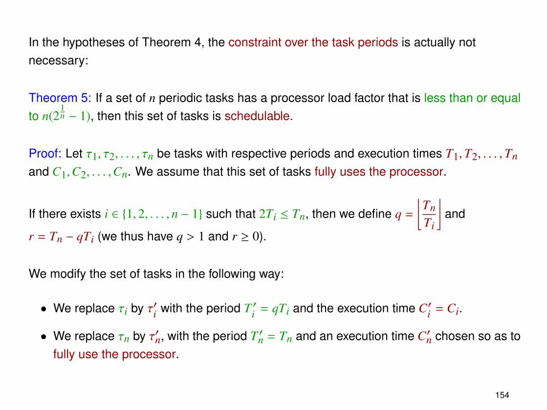
In the hypotheses of Theorem 4, the constraint over the task periods is actually notnecessary:
Theorem 5: If a set of n periodic tasks has a processor load factor that is less than or equalto n(2
1n − 1), then this set of tasks is schedulable.
Proof: Let τ1, τ2, . . . , τn be tasks with respective periods and execution times T1,T2, . . . ,Tn
and C1,C2, . . . ,Cn. We assume that this set of tasks fully uses the processor.
If there exists i ∈ {1, 2, . . . , n − 1} such that 2Ti ≤ Tn, then we define q =
⌊TnTi
⌋and
r = Tn − qTi (we thus have q > 1 and r ≥ 0).
We modify the set of tasks in the following way:
• We replace τi by τ′i with the period T ′i = qTi and the execution time C′i = Ci.
• We replace τn by τ′n, with the period T ′n = Tn and an execution time C′n chosen so as tofully use the processor.
154
Ci Ci Ci ≤ Ci
Ti 2Ti (q − 1)Ti qTi
C′i = Ci
T ′i
Tn0
t
In the critical zone of τn, the amount of execution time used by τi and leaved unused by τ′iis at most equal to (q − 1)Ci. Therefore, one has
C′n −Cn ≤ (q − 1)Ci.
After modifying the set of tasks, the processor load factor U′ becomes equal to
U′ ≤ U +C′iT ′i−
CiTi
+(q − 1)Ci
Tn
where U is the processor load factor of the initial set of tasks.
One then obtains
U′ ≤ U + Ci
(1
qTi−
1Ti
+q − 1
Tn
).
155
Since we have qTi ≤ Tn, this leads to
1qTi−
1Ti
+q − 1
Tn≤
1qTi−
1Ti
+q − 1qTi
≤ 0.
As a consequence, we have U′ ≤ U. This implies that our modification of the set of tasksdid not increase the processor load factor.
By repeatedly performing such a modification, one eventually obtains a set of tasks towhich Theorem 4 can be applied.
156
The limit processor load factor
The value of UL decreases with the number n of tasks. Indeed,
dULdn
=
(1 −
ln 2n
)2
1n − 1
= (1 − x)ex − 1,
by defining x =ln 2n
. Let us show that we have
(1 − x)ex < 1
for all x > 0 (which impliesdULdn
< 0 for all n > 0).
For all x > 0, we have ex = 1 + x +x2
2!+
x3
3!+ · · · , hence
(1 − x)ex = (1 − x) + (1 − x)x + (1 − x)x2
2!+ (1 − x)
x3
3!+ · · ·
= 1 −(1 −
12!
)x2 −
(12!−
13!
)x3 −
(13!−
14!
)x4 + · · ·
< 1.
157
For an asymptotically large number of tasks, we obtain
limn→∞
UL(n) = limn→∞
n(21n − 1)
= limn→∞
21n − 1
1n
= limn→∞
ln 2n2 2
1n
1n2
= ln 2
≈ 0.69
158
In summary, we have the following result:
Theorem 6: If a set of periodic tasks has a processor load factor that is less than or equalto ln 2, then this set of tasks is schedulable.
Conclusion: The following algorithm can be used for checking efficiently whether a set of nperiodic tasks with a processor load factor equal to U is schedulable or not:
1. If U > 100%, then the set of tasks is not schedulable;
2. If U ≤ 69%, then the set of tasks is schedulable;
3. If U ≤ n(21n − 1), then the set of tasks is schedulable;
4. Otherwise, one performs an exact scheduling simulation, based on a RMS prioritiesassignment.
159
Notes
• In situations where U ≤ 69% for the periodic tasks, the processor does not have toremain unused during 31% of the time! One can instead run low-priority tasks that arenot bound by real-time constraints.
• For some specific class of sets of tasks, one can obtain UL = 100%, which guaranteesthat every set of tasks for which U ≤ 100% is schedulable.
Example: Let τ1, τ2, . . . , τn be a set of tasks with respective periods and executiontimes T1,T2, . . . ,Tn and C1,C2, . . . ,Cn, such that
– 0 < T1 ≤ T2 ≤ · · · ≤ Tn,
– ∀i, j : i < j ⇒ T j is an integer multiple of Ti,
– U =
n∑i=1
CiTi≤ 1.
160
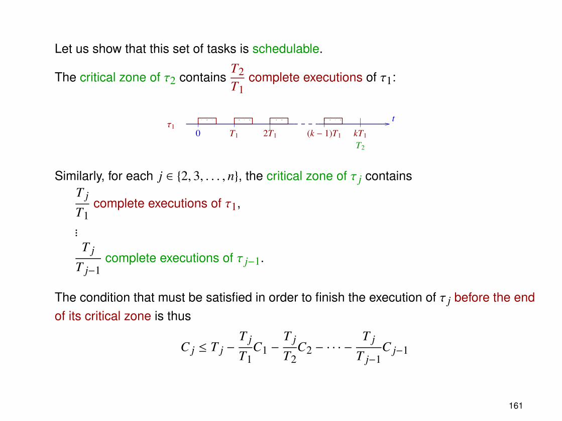
Let us show that this set of tasks is schedulable.
The critical zone of τ2 containsT2T1
complete executions of τ1:
τ1T1 2T1 (k − 1)T1 kT10
T2
t
Similarly, for each j ∈ {2, 3, . . . , n}, the critical zone of τ j containsT j
T1complete executions of τ1,
...T j
T j−1complete executions of τ j−1.
The condition that must be satisfied in order to finish the execution of τ j before the endof its critical zone is thus
C j ≤ T j −T j
T1C1 −
T j
T2C2 − · · · −
T j
T j−1C j−1
161
After simplification, this condition becomes
C1T1
+C2T2
+ · · · +C j
T j≤ 1,
which immediately follows from the hypothesis U ≤ 1.
162
Chapter 8
Complex timed systems
163
Introduction
In order to analyze the properties of a complex system, it is not always sufficient to studythe individual behavior of its components.
Example: An embedded system controlling a railroad crossing is composed of the followingelements:
• Two sensors located on the tracks 1000 meters before and 100 meters after thecrossing, aimed at detecting (respectively) that a train approaches or has passed thecrossing.
• A receiver that processes the signals emitted by the sensors, and sends orders toopen or close the gate.
receiver
1000 m 100 m
164
The following information is known:
• The speed of the approaching trains is between 48 and 52 m/s. Then, after reachingthe first sensor, their speed is reduced to a value between 40 and 52 m/s.
• After it receives a signal from a sensor, the receiver waits for at most 5 seconds beforesending an order to close or to open the gate. During this delay, the receiver ignoresincoming signals.
• The gate is closed (resp. open) when its angle is equal to 0 (resp. 90) deg. The gate isable to move at the rate of 20 deg/s.
• Two successive trains are always separated by at least 1600 m.
Question: Is the gate always closed when a train passes the crossing?
165
Modeling a system
In order to analyze the properties of a system, the first step consists in building a model,i.e., an abstract representation of the system that describes its relevant properties withoutany ambiguity.
For embedded applications, the modeling formalism must be able to express
• operations on integer variables (used as counters, sequence numbers, identifiers, . . . ),as well as on real variables (for representing positions, speeds, delays, . . . ).
• discrete state transitions (e.g., incrementing a counter) as well as continuous evolutionlaws (e.g., constant-speed movement).
• composition of elementary systems into a more complex entity.
166
Hybrid systems
Hybrid systems are a modeling formalism that meets those requirements.
Syntax:
A hybrid system is composed of:
• a finite number p of processes P1, P2, . . . , Pp,
• a finite number n of variables x1, x2, . . . , xn, grouped together into a vector ~x ∈ Rn,
• a finite set L of synchronization labels.
Each process Pi is represented by a graph (Vi, Ei), where
• Vi est a finite set of control locations,
• Ei ⊆ Vi × Vi is a finite set of transitions.
167
Each control location v ∈ Vi is associated with:
• An activity dif (v), expressed as a conjunction of linear constraints over the variablesx1, x2, . . . , xn and their first temporal derivative x1, x2, . . . , xn.
• An invariant inv(v), expressed as a conjunction of linear constraints over the variablesx1, x2, . . . , xn.
Each transition e ∈ Ei is associated with:
• A guard guard(e), that represents a condition that must be satisfied in order to enablethis transition.
• An action act(e), composed of constraints that specify how the values of the variablesare modified when this transition is followed.
In practice, the guard and the action can be combined into a conjunction of constraintsover the values of the variables before (x1, x2, x3, . . . ) and after (x′1, x′2, x′3, . . . )following the transition.
168
• An optional label sync(e) ∈ L that makes it possible to synchronize this transition witha transition belonging to another process.
Finally, one defines an initial control location for each process, and assigns a set ofpossible initial values for each variable, specified as a conjunction of linear constraints.
169
Example: Process modeling the behavior of a train and the two sensors.
• The distance between the train and the crossing is represented by a variable x1.
• The signals emitted by the sensors are modeled by two synchronization labels appand exit .
170
[1] [2]
[3]
exit
app
x1 ≥ 15001000 ≤ x1
x1 = 10000 ≤ x1 ≤ 1000
x1 = 100
x′1 ≥ 1500 x1 = 0
x1 ≤ 100
−52 ≤ x1 ≤ −48
40 ≤ x1 ≤ 52
−52 ≤ x1 ≤ −40
171
Process modeling the receiver:
• The delay between receiving a sensor signal and sending an order to the gate isrepresented by a variable x2.
• The labels raise and lower model the orders sent to the gate.
172
[2] [3]
[1]
x2 = 1 x2 = 1
x2 = 0
0 ≤ x2 ≤ 5
x′2 = 0 x′2 = 0
0 ≤ x2 ≤ 5
x2 = 0
exit
raise
exitapp
lower
exit
app app
173
Process modeling the gate:
• The variable x3 represents the angular position of the gate.
• The labels raise and lower correspond to the orders received.
174
[1]
raise
x3 = 20 x3 = 0
[2]
raise
lowerraise
lower
raise
[3]
x3 = −20
[4]
x3 = 0
lower lower
0 ≤ x3 ≤ 90 x3 = 90x3 = 90x3 = 90
0 ≤ x3 ≤ 90x3 = 0
x3 = 0
175
Semantics:
At any given time, the current state of a hybrid system is characterized by
• a control location for each process, and
• a value for each variable.
The state of a system can evolve in two ways:
• By letting time elapse (time steps). The control locations of processes stayunchanged, and the values of the variables evolve according to the invariants andactivities associated to these locations.
• By following transitions (transition steps). One can either
– follow a single unlabeled transition, or
– follow a pair of transitions belonging to different processes and sharing the samesynchronization label.
176
In both cases, a transition can only be followed provided that its guard is satisfied bythe current variable values.
When a transition is followed, the variable values are modified according to the actionassociated to the transition. The invariant of the destination location must be satisfiedby the new variable values (otherwise, the transition cannot be followed).
A state s2 is reachable from a state s1 if there exists a finite sequence of time steps andtransition steps that lead from s1 to s2.
A state s is reachable if it is reachable from an initial state.
177
Example: The state ([2], [2], [2], 800, 4, 90) of the railroad crossing controller modelcorresponds to
• the control location [2] for each process.
• the respective values 800, 4 and 90 for the variables x1, x2 and x3.
• “`−→” corresponds to following a pair of transitions sharing the synchronization label `.
178
Executions of a hybrid system
An execution of a hybrid system is an infinite sequence s1, s2, s3, . . . of states such that:
• s1 is an initial state of the system.
• For each i, the state si+1 is reachable from the state si in a time δi ≥ 0.
Note: A hybrid system generally admits several different executions (non-determinism).Indeed,
• The time spent at a control location may not be precisely constrained by the invariant.
• A control location can have several outgoing transitions enabled at a given time.
An execution s1, s2, s3, . . . beginning at time t = 0 is said to be divergent if for every T > 0,there exists i such that the state si is reached later than time t = T .
179
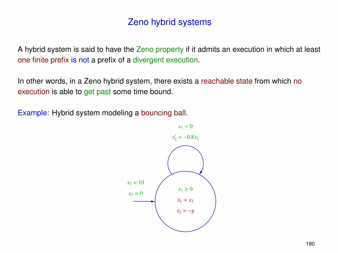
Zeno hybrid systems
A hybrid system is said to have the Zeno property if it admits an execution in which at leastone finite prefix is not a prefix of a divergent execution.
In other words, in a Zeno hybrid system, there exists a reachable state from which noexecution is able to get past some time bound.
Example: Hybrid system modeling a bouncing ball.
x2 = 0
x1 = 10x1 ≥ 0
x1 = 0
x′2 = −0.8x2
x1 = x2
x2 = −g
180
x1
t
Remarks:
• Such models are inconsistent with physical reality and must be avoided!
• For some restricted classes of hybrid systems, automatic methods have beendeveloped for transforming any given model into another one that does not have theZeno property, and admits the same divergent executions.
181
State-space exploration
A large number of interesting properties of a hybrid system can be checked by computingits reachable states.
This computation can be carried out by building, from every initial state, a tree in whicheach node q represents a reachable state s(q), and the children of q correspond to thestates that are reachable from s(q) by
• a time step, or
• a transition step.
Problems:
• The system may have infinitely many initial states.
• The time spent at a control location may take an infinite number of possible values,which leads to trees of infinite degree.
• Since executions are infinite, the trees also have an infinite depth.
182
Solutions:
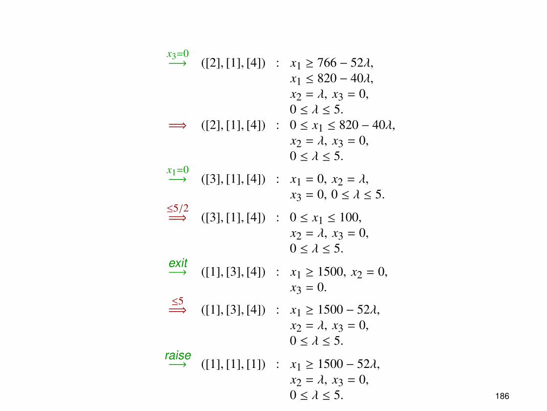
• Sets of states sharing the same control locations and differing only in the elapsed timein those locations can be grouped into regions. A tree can be built in which the nodesare associated with regions instead of individual states.
• At each exploration step, a first operation saturates the current region by letting timeelapse during all possible delays. Then, the enabled transitions are individuallyfollowed, creating new branches.
• The branches of the exploration tree that only contain already visited states can bepruned.
Notes:
• Several exploration strategies are possible: depth-first search (DFS), breadth-firstsearch (BFS), . . .
183
• For general hybrid systems, the region tree can still be infinite. It is however possibleto define restricted classes of models, for which a finite region tree can always becomputed.
Example: Timed automata are hybrid systems in which
– the activities are of the form xi = 1,
– all invariants, guards and actions are conjunctions of constraints of the form xi#c orxi − x j#c, where c is an integer number, and # ∈ {<,≤,=,≥, >}.
• Some tools are available for exploring automatically the state space of hybrid systems(e.g., HyTech) or timed automata (e.g., Uppaal).
Notes: These tools
– represent and handle regions with the help of dedicated data structures, based onlogic formulas, convex polyhedra, difference matrices, . . .
– are able to check properties that go beyond simple reachability.
• In this example, the regions correspond to the sets of states obtained after eachtime-step operation (denoted by “=⇒”).
• Checking whether the gate is always closed when a train reaches the crossingamounts to verifying that in each reachable region, x1 = 0 implies x3 = 0.
• This particular system shows a very deterministic behavior: In each reachable state,there is at most one transition (or a pair of synchronized transitions) that is enabled.