+ All Categories
Home > Documents > Embedded WiFi Module User Manual - Lilly Electronics WiFi Module User Manual Version : V4.5...

Embedded WiFi Module User Manual - Lilly Electronics WiFi Module User Manual Version : V4.5...

Date post: 21-May-2018
Category:
Upload: hoangtuyen
View: 232 times
Download: 0 times
Share this document with a friend
79
USR-WIFI232-A/B/C User Manual http://en.usr.cn Jinan USR IOT Technology Limited Page 1 of 79 [email protected] USR-WIFI232- USR-WIFI232- USR-WIFI232- USR-WIFI232-A/B/C A/B/C A/B/C A/B/C Embedded Embedded Embedded Embedded WiFi WiFi WiFi WiFi Module Module Module Module User User User User Manual Manual Manual Manual VersionV4.5 Remarks: Remarks: Remarks: Remarks: This module is applicable to USR-WIFI232-A/B/C and its derivatives, for example USR-WIFI232-2/610. For USR-WIFI232-G/T/S, please refer to the corresponding document.
Transcript

USR-WIFI232-A/B/C User Manual http://en.usr.cn

Jinan USR IOT Technology Limited Page 1 of 79 [email protected]

USR-WIFI232-USR-WIFI232-USR-WIFI232-USR-WIFI232-A/B/CA/B/CA/B/CA/B/C

EmbeddedEmbeddedEmbeddedEmbedded WiFiWiFiWiFiWiFi ModuleModuleModuleModule UserUserUserUser ManualManualManualManualVersion:V4.5

Remarks:Remarks:Remarks:Remarks: This module is applicable to USR-WIFI232-A/B/C and its derivatives, for example

USR-WIFI232-2/610. For USR-WIFI232-G/T/S, please refer to the corresponding document.

USR-WIFI232-A/B/C User Manual http://en.usr.cn

Jinan USR IOT Technology Limited Page 2 of 79 [email protected]

TableTableTableTable OfOfOfOf ContentsContentsContentsContents

1 Quick Start..................................................................................................................................................61.1 Hardware connect.......................................................................................................................... 61.2 Network connection........................................................................................................................71.3 communication test........................................................................................................................ 8

2 Product Overview...................................................................................................................................... 82.1 General Description....................................................................................................................... 92.2 Device Features..............................................................................................................................92.3 Device Paremeters...................................................................................................................... 102.4 Key Application.............................................................................................................................102.5 Package Information....................................................................................................................11

2.5.1 Recommended Reflow Profile.........................................................................................112.5.2 Device Handling Instruction (Module IC SMT Preparation)........................................112.5.3 Shipping Information.........................................................................................................12

3 Hardware Introduction............................................................................................................................ 123.1 Pins Definition...............................................................................................................................12

3.1.1 USR-WIFI232-A/B Pins Definition..................................................................................123.1.2 USR-WIFI232-Ca/Cb Pins Definition.............................................................................14

3.2 Mechanical Size........................................................................................................................... 153.2.1 USR-WIFI232-A/B.............................................................................................................153.2.2 USR-WIFI232-Ca/Cb........................................................................................................16

3.3 Antenna..........................................................................................................................................173.3.1 On-board Chip Antenna................................................................................................... 173.3.2 External Antenna...............................................................................................................17

3.4 Evaluation Kit................................................................................................................................183.5 Hardware Reference Design......................................................................................................20

3.5.1 Hardware Typical Application..........................................................................................203.5.2 10/100M Ethernet Interface.............................................................................................21

3.5.2.1 Ethernet Connection with Transformer...............................................................213.5.2.2 Ethernet Connection without Transformer......................................................... 22

3.5.3 UART Interface..................................................................................................................243.5.4 Power Interface................................................................................................................. 24

4 Modules Function Description............................................................................................................... 244.1 User configuration process.........................................................................................................254.2 Working mode...............................................................................................................................25

4.2.1 Transparent Transmission Mode.................................................................................... 254.2.2 Serial command mode..................................................................................................... 264.2.3 GPIO 1 mode/GPIO 2 mode........................................................................................... 27

4.3 Wireless Networking....................................................................................................................274.3.1 STA......................................................................................................................................284.3.2 AP........................................................................................................................................284.3.3 AP+STA.............................................................................................................................. 29

USR-WIFI232-A/B/C User Manual http://en.usr.cn

Jinan USR IOT Technology Limited Page 3 of 79 [email protected]

4.4 Ethernet Interface Communication............................................................................................304.4.1 USR-WIFI232-A/B/C Ethernet Interface Networking (As AP).................................... 304.4.2 USR-WIFI232-A/B/C Ethernet Interface Networking (As STA, N-Ver)......................314.4.3 USR-WIFI232-A/B/C Ethernet Interface Networking (As STA, Z-Ver)......................32

4.5 WI-FI parameter setting...............................................................................................................324.5.1 Auto- Frequency Function............................................................................................... 324.5.2 Security...............................................................................................................................324.5.3 Search Function for STA..................................................................................................334.5.4 Address Binding................................................................................................................ 33

4.6 UART Frame Scheme................................................................................................................. 334.6.1 UART Free-Frame............................................................................................................ 334.6.2 UART Auto-Frame............................................................................................................ 34

4.7 Network Setting............................................................................................................................ 344.7.1 Socket A............................................................................................................................. 344.7.2 Socket B.............................................................................................................................35

4.8 New function................................................................................................................................. 354.8.1 TCP password authentication......................................................................................... 354.8.2 Upload ID........................................................................................................................... 354.8.3 Self-adaption Baudrate.................................................................................................... 364.8.4 WEB IO...............................................................................................................................364.8.5 Keepalive............................................................................................................................36

4.9 Palmodic Signal............................................................................................................................364.10 Parameters Configuration.........................................................................................................374.11 Firmware Upgrade..................................................................................................................... 37

5 Web Accessing and AT+instruction set................................................................................................ 385.1 Configuration via Web Accessing.............................................................................................. 38

5.1.1 Open Web Management Interface................................................................................. 385.1.2 Mode Selection Page....................................................................................................... 395.1.3 AP Interface Setting Page................................................................................................395.1.4 STA Interface Setting Page............................................................................................. 405.1.5 Application Setting Page..................................................................................................405.1.6 WEB IO...............................................................................................................................425.1.7 Device Management Page..............................................................................................42

5.2 AT+instruction Introduction......................................................................................................... 435.2.1 Configuration Mode.......................................................................................................... 43

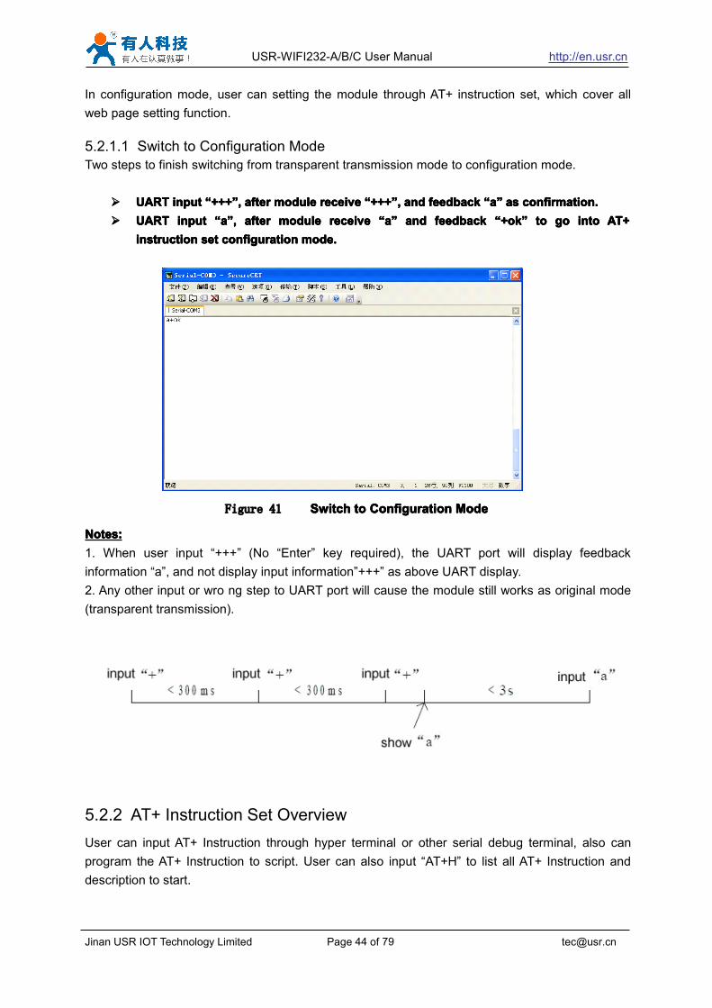
5.2.1.1 Switch to Configuration Mode..............................................................................445.2.2 AT+ Instruction Set Overview..........................................................................................44

5.2.2.1 Instruction Syntax Format.................................................................................... 465.2.2.2 AT+ Instruction Set................................................................................................ 47

5.2.2.2.1 AT+E.............................................................................................................485.2.2.2.2 AT+ENTM....................................................................................................495.2.2.2.3 AT+NETP.....................................................................................................495.2.2.2.4 AT+UART.....................................................................................................495.2.2.2.5 AT+ UARTF.................................................................................................50

USR-WIFI232-A/B/C User Manual http://en.usr.cn

Jinan USR IOT Technology Limited Page 4 of 79 [email protected]

5.2.2.2.6 AT+ UARTFT...............................................................................................505.2.2.2.7 AT+ UARTFL...............................................................................................505.2.2.2.8 AT+TMODE.................................................................................................515.2.2.2.9 AT+WMODE................................................................................................515.2.2.2.10 AT+WSKEY...............................................................................................515.2.2.2.11 AT+WSSSID............................................................................................. 525.2.2.2.12 AT+ WSLK.................................................................................................525.2.2.2.13 AT+WEBU................................................................................................. 525.2.2.2.14 AT+WAP.................................................................................................... 535.2.2.2.15 AT+WAKEY...............................................................................................535.2.2.2.16 AT+HIDESSID.......................................................................................... 545.2.2.2.17 AT+MSLP.................................................................................................. 545.2.2.2.18 AT+WSCAN.............................................................................................. 555.2.2.2.19 AT+ TCPLK............................................................................................... 555.2.2.2.20 AT + TCPDIS............................................................................................ 555.2.2.2.21 AT+ WANN................................................................................................555.2.2.2.22 AT+ LANN................................................................................................. 565.2.2.2.23 AT+DHCPDEN......................................................................................... 565.2.2.2.24 AT+ DHCPGW..........................................................................................565.2.2.2.25 AT+ TCPTO...............................................................................................575.2.2.2.26 AT+ MAXSK..............................................................................................575.2.2.2.27 AT+TCPB...................................................................................................575.2.2.2.28 AT+TCPPTB............................................................................................. 585.2.2.2.29 AT+TCPADDB.......................................................................................... 585.2.2.2.30 AT+TCPTOB.............................................................................................585.2.2.2.31 AT+TCPLKB..............................................................................................585.2.2.2.32 AT+EPHY.................................................................................................. 595.2.2.2.33 AT+STTC...................................................................................................595.2.2.2.34 AT+DOMAIN............................................................................................. 595.2.2.2.35 AT+FRLDEN............................................................................................. 605.2.2.2.36 AT+FUDLX................................................................................................605.2.2.2.37 AT+MMID...................................................................................................605.2.2.2.38 AT+IDFIR...................................................................................................605.2.2.2.39 AT+IDEVE................................................................................................. 615.2.2.2.40 AT+AABR.................................................................................................. 615.2.2.2.41 AT+RELD...................................................................................................615.2.2.2.42 AT+Z...........................................................................................................625.2.2.2.43 AT+MID......................................................................................................625.2.2.2.44 AT+VER.....................................................................................................625.2.2.2.45 AT+H.......................................................................................................... 62

6 USR-WIFI232-A/B/C Usage Introduction.............................................................................................626.1 Module Debug.............................................................................................................................. 62

6.1.1 Software Debug Tools...................................................................................................... 626.1.2 Network Connection......................................................................................................... 63

USR-WIFI232-A/B/C User Manual http://en.usr.cn

Jinan USR IOT Technology Limited Page 5 of 79 [email protected]

6.1.3 Debug................................................................................................................................. 636.2 Use Cases.....................................................................................................................................65

6.2.1 Wireless Control Application........................................................................................... 656.2.2 Remote Management Application.................................................................................. 666.2.3 Transparent Serial Port Application................................................................................666.2.4 Wireless Data Acquisition Card Application..................................................................67

Appendix A: Questions and Answers................................................................................................ 69Q1: How to configure transparent serial port application (TCP protocol) with two WIFImodules?..............................................................................................................................................69Q2: Where to Set WIFI Module LAN IP and WAN IP through Web Page?..............................70Q3: How to configure transparent serial port application (UDP protocol) with two WIFImodules?..............................................................................................................................................70Q4: Where to set USR-WIFI232-A/B/C module network protocol (TCP/UDP)?....................... 71Q5: How to configure transparent serial port application: Two WIFI modules all configured asSTA and connection through AP?.....................................................................................................72Q6: How to avoid IP address confliction when apply USR-WIFI232-A/B/C module?.............. 73Q7: PC works as server, all WIFI modules works as data acquisition card and connect withPC, how to configure this application?............................................................................................ 73Q8: WIFI module support UDP multicast?......................................................................................74Q9:WIFI module operates in STA mode, the PC how to get the IP module?............................ 74

Appendix b: evb reference design......................................................................................................76Appendix c: external power shutdown mode reference design ................................................ 77Appendix e: Contact Information ........................................................................................................ 78Appendix f: Disclaimer............................................................................................................................... 78Appendix g: History.................................................................................................................................... 79

USR-WIFI232-A/B/C User Manual http://en.usr.cn

Jinan USR IOT Technology Limited Page 6 of 79 [email protected]

1111 QuickQuickQuickQuick StartStartStartStart

USR-WIFI232 series product is used to transmit data between RS232 and WIFI TCPIPtransparently, user can update the product to WIFI control without knowing the WIFI and TCPIPdetail. All the convert work is done by the module. For users, the RS232 side is only as a serialdevice,the WIFI side is TCPIP Socket data. User can setup the work detail by sample settingswhich can setup via inside web pages or RS232 port. The setup work only need do once, then itwill save the setting forever.This chapter is a user guide for USR-WIFI232 series products. We suggest users follow the guideto test module at first, and will have a good understanding of the modules. Users can also choosethe chapter which you are interested in to read. For specific details and instructions, please referto the following chapters.

1.11.11.11.1 HardwareHardwareHardwareHardware connectconnectconnectconnect

In order to test WIFI module, we need connect module RS232 to PC and also WIFI to PC.In order to test the communication between serial and WIFI network, we need to connect theserial port to PC, and also connect WIFI networks to PC. Due to the special need both WIFI andserial, we use PC which add USB WIFI network Card such as the following picture.

Figure 1 hardwarehardwarehardwarehardware connectionconnectionconnectionconnection diagramdiagramdiagramdiagram

About the serial connection, because the module RS232 is 3.3V TTL level, the computer can notconnect to module directly, the user needs to have a TTL to RS232 adapter cable and thenconnect to the computer. in order to facilitate the test, we provide USR-WIFI232-A/B/C evaluationboard for users to choose.

USR-WIFI232-A/B/C User Manual http://en.usr.cn

Jinan USR IOT Technology Limited Page 7 of 79 [email protected]

1.21.21.21.2 NetworkNetworkNetworkNetwork connectionconnectionconnectionconnection

The following is the USR-WIFI232-A module example,Other modules are the same.Open Wi-Fi,search network, as shown in below, USR-WIFI232-AP_3378 is the default network name (SSID)of the module.

Figure 2 WIFIWIFIWIFIWIFI SearchSearchSearchSearch

Join the network, choose to automatically obtain IP, WIFI module supports DHCP Server featureand is enabled by default.

Figure 3 WIFIWIFIWIFIWIFI connectionconnectionconnectionconnection

Now, nlink led of USR-WIFI232-A Evaluation Board is lighting.

USR-WIFI232-A/B/C User Manual http://en.usr.cn

Jinan USR IOT Technology Limited Page 8 of 79 [email protected]

1.31.31.31.3 communicationcommunicationcommunicationcommunication testtesttesttest

Module’s default setting:� SSID:SSID:SSID:SSID:USR-WIFI232-A;� EncryptionEncryptionEncryptionEncryption modemodemodemode::::open,none;� UART:UART:UART:UART:57600,8,1,None;� NetworkNetworkNetworkNetwork parametersparametersparametersparameters:TCP,Server,8899,10.10.100.254;� IP:IP:IP:IP:10.10.100.254;We just need to follow the parameters of the corresponding set of network communicationparameters, you can make serial <--> WIFI communication, the steps are as follows:1. Open test software USR-TCP232-Test;2. COM Settings area (left):Choose COM port witch has connect the module, there is COM3, choose band rate to 57600, thisis the default band rate of WIFI module, Click Open COM port.3. Net Settings area (right):Choose TCP client mode, Server IP write 10.10.100.254, it is the WIFI default IP address, Serverport to 8899, It is the default Port the WIFI module listen, Click Connect to link to the module.Now, you can test send data between RS232 and WIFI.COM port to WIFI: PC RS232 -> Module RS232 -> Module WIFI -> PC WIFI.WIFI to COM port: PC WIFI -> Module WIFI -> Module RS232 -> PC RS232.

Figure 4 serialserialserialserial //// networknetworknetworknetwork transmissiontransmissiontransmissiontransmission testtesttesttest

2222 ProductProductProductProduct OverviewOverviewOverviewOverview

USR-WIFI232-A/B/C User Manual http://en.usr.cn

Jinan USR IOT Technology Limited Page 9 of 79 [email protected]

2.12.12.12.1 GeneralGeneralGeneralGeneral DescriptionDescriptionDescriptionDescription

USR-WIFI232-A/B/C module is an integration of 802.11 b/g/n wi-fi module,which provide awireless interface to any equipment with a Serial interface for data transfer.The module used to MAC, baseband chip, RF transceiver unit, as well as the poweramplifier;Embedded firmware support wi-fi protocols and configuration, as well as the networkTCP/IP protocol stack.USR-WIFI232-A/B/C uses the industry's highest performance embedded industrial structure, andfor the application of smart furniture, smart grid, handheld devices, personal medical, industrialcontrol, etc. These data fields, do a professional optimization.USR-WIFI232-A/B/C as a hot spot can accommodate 32 clients simultaneously wi-fi access, butalso can accommodate 32 TCP client, specific models and parameters of the series modules areas follows:USR-WIFI232-A 40mm x 25mm, 2x7 2mm Connector, Built-in antennaUSR-WIFI232-B 40mm x 25mm, 2x7 2mm Connector, I-PEX connectorUSR-WIFI232-Ca 40mm x 25mm, SMT Footprint, Built-in antennaUSR-WIFI232-Cb 40mm x 25mm, SMT Footprint, I-PEX connector

2.22.22.22.2 DeviceDeviceDeviceDevice FeaturesFeaturesFeaturesFeatures

���� SupportSupportSupportSupport IEEE802.11b/g/nIEEE802.11b/g/nIEEE802.11b/g/nIEEE802.11b/g/n WirelessWirelessWirelessWireless StandardsStandardsStandardsStandards

���� SupportSupportSupportSupport TCP/IP/UDPTCP/IP/UDPTCP/IP/UDPTCP/IP/UDP NetworkNetworkNetworkNetwork ProtocolsProtocolsProtocolsProtocols

���� SupportSupportSupportSupport UART/GPIO/EthernetUART/GPIO/EthernetUART/GPIO/EthernetUART/GPIO/Ethernet DataDataDataData InterfaceInterfaceInterfaceInterface

���� SupportSupportSupportSupport WorkWorkWorkWork AsAsAsAs STA/APSTA/APSTA/APSTA/AP/AP+STA/AP+STA/AP+STA/AP+STAModeModeModeMode

���� SupportSupportSupportSupport Router/BridgeRouter/BridgeRouter/BridgeRouter/Bridge ModeModeModeMode NetworkingNetworkingNetworkingNetworking

���� SupportSupportSupportSupport Internal/ExternalInternal/ExternalInternal/ExternalInternal/External AntennaAntennaAntennaAntenna OptionOptionOptionOption

���� SupportSupportSupportSupport TransparentTransparentTransparentTransparent TransmissionTransmissionTransmissionTransmission ModeModeModeMode

���� SupportSupportSupportSupport AT+AT+AT+AT+ InstructionInstructionInstructionInstruction SetSetSetSet forforforfor ConfigurationConfigurationConfigurationConfiguration

���� SupportSupportSupportSupport FriendlyFriendlyFriendlyFriendly WebWebWebWeb ConfigurationConfigurationConfigurationConfiguration PagePagePagePage

���� SupportSupportSupportSupport PalmodicPalmodicPalmodicPalmodic SignalSignalSignalSignal

���� SupportSupportSupportSupport UARTUARTUARTUART Auto-FrameAuto-FrameAuto-FrameAuto-Frame FunctionFunctionFunctionFunction

���� SingleSingleSingleSingle +3.3V+3.3V+3.3V+3.3V PowerPowerPowerPower SupplySupplySupplySupply

���� SmallSmallSmallSmall Size:Size:Size:Size: 25252525 xxxx 40mm40mm40mm40mm

���� FCC/CEFCC/CEFCC/CEFCC/CE CertificatedCertificatedCertificatedCertificated

USR-WIFI232-A/B/C User Manual http://en.usr.cn

Jinan USR IOT Technology Limited Page 10 of 79 [email protected]

2.32.32.32.3 DeviceDeviceDeviceDevice ParemetersParemetersParemetersParemeters

Table 1 USR-WIFI232-A/B/C Module Technical Specifications

ClassClassClassClass ItemItemItemItem ParametersParametersParametersParameters

WirelessWirelessWirelessWirelessParametersParametersParametersParameters

Certification FCC/CEWireless standard 802.11 b/g/nFrequency range 2.412GHz-2.484GHz

Transmit Power

802.11b: +20 dBm (Max.)802.11g: +18 dBm (Max.)802.11n: +15 dBm (Max.)Configurable

Receiver Sensitivity802.11b: -89 dBm802.11g: -81dBm802.11n: -71dBm

Antenna OptionExternal:I-PEX ConnectorInternal:On-board chip antenna

HardwareHardwareHardwareHardwareParametersParametersParametersParameters

Data InterfaceUART: 1200bps - 230400bpsGPIOsEthernet: 100Mpbs

Operating Voltage 3.3V (+/-5%)Operating Current 170mA~300mAOperatingTemperature

-25℃- 85℃

Storage Temperature -40℃- 125℃Dimensions and Size 25×40×8mm

SoftwareSoftwareSoftwareSoftwareParametersParametersParametersParameters

Network Type Station /AP mode/STA+APSecurity Mechanisms WEP/WAP-PSK/WAP2-PSK/WAPIEncryption WEP64/WEP128/TKIP/AESWork Mode Transparent TransmissionSerial command AT+instruction set

Network Protocol TCP/UDP/ARP/ICMP/DHCP/DNS/HTTP

Max. TCP Connection 32User Configuration Web Server+AT command config.

2.42.42.42.4 KeyKeyKeyKey ApplicationApplicationApplicationApplication

� Remote equipment monitoring� Industrial sensors and controls� Asset tracking and telemetry� Home automation� Medical devices

USR-WIFI232-A/B/C User Manual http://en.usr.cn

Jinan USR IOT Technology Limited Page 11 of 79 [email protected]

2.52.52.52.5 PackagePackagePackagePackage InformationInformationInformationInformation

2.5.1 Recommended Reflow Profile

Figure 5 ReflowReflowReflowReflow SolderingSolderingSolderingSoldering ProfileProfileProfileProfile

Table 2 Reflow Soldering Parameter

Note:Note:Note:Note:1. Recommend to supply N2 for reflow oven.2. N2 atmosphere during reflow (O2<300ppm).

2.5.2 Device Handling Instruction (Module IC SMT Preparation)� Shelf life in sealed bag: 12 months, at <30℃ and <60% relative humidity (RH)� After bag is opened, devices that will be re-baked required after last baked with window time

168 hours.� Recommend to oven bake with N2 supplied.� Baked required with 24 hours at 125±5℃ before rework process for two modules, one is

new module and two is board with module.� Recommend to store at ≦10% RH with vacuum packing.� If SMT process needs twice reflow:(1) Top side SMT and reflow à (2) Bottom side SMT and reflowCase 1: Wifi module mounted on top side. Need to bake when bottom side process over 168hours window time, no need to bake within 168 hours.Case 2: Wifi module mounted on bottom side, follow normal bake rule before process.Note:Window time means from last bake end to next reflow start that has 168 hours space.

NO.NO.NO.NO. ItemItemItemItem TemperatureTemperatureTemperatureTemperature (Degree)(Degree)(Degree)(Degree) Time(Sec)Time(Sec)Time(Sec)Time(Sec)1 Reflow Time Time of above 220 35~55 sec2 Peak-Temp 260 max

USR-WIFI232-A/B/C User Manual http://en.usr.cn

Jinan USR IOT Technology Limited Page 12 of 79 [email protected]

2.5.3 Shipping Information

Figure 6 ShippingShippingShippingShipping InformationInformationInformationInformation

TRAYTRAYTRAYTRAY Size: 420*245*34 mmNote:Note:Note:Note:1 tray = 5*20 pcs = 100 pcs1 box = 2 trays = 2*100 pcs = 200pcs1 carton = 4 boxes = 4*200 pcs = 800pcs

3333 HardwareHardwareHardwareHardware IntroductionIntroductionIntroductionIntroduction

3.13.13.13.1 PinsPinsPinsPins DefinitionDefinitionDefinitionDefinition

3.1.1 USR-WIFI232-A/B Pins Definition

Figure 7 USR-WIFI232-USR-WIFI232-USR-WIFI232-USR-WIFI232-A/BA/BA/BA/B

USR-WIFI232-A/B/C User Manual http://en.usr.cn

Jinan USR IOT Technology Limited Page 13 of 79 [email protected]

P H Y _T X +

P H Y _R X +

nR eady /G P IO 9

R ESET

U A RT_R T S /G P IO 5

U A RT_T X D /G P IO 3

G N D

P H Y _T X -

P H Y _R X -

nR eload /G P IO 1 0

nL ink /G P IO 8

U A RT_C T S /G P IO 6

U A RT_R X D /G P IO 4

3.3V

Figure 8 USR-WIFI232-USR-WIFI232-USR-WIFI232-USR-WIFI232-A/BA/BA/BA/B PinsPinsPinsPins MapMapMapMap

Table 3 USR-WIFI232-A/B Pins DefinitionPinPinPinPin DescriptionDescriptionDescriptionDescription NameNameNameName DirectiDirectiDirectiDirectioooo

nnnnNoteNoteNoteNote

1111 Ground--GND GND Power Ground2222 VCC 3.3V@350mA 3.3V Power 3.3V @ 350mA power input3333 UART Data Transmit UART_TXD O If not use UART function,

this 4 pins can be configuredas GPIO pins, and canchange GPIO pin statusthrough AT command

GPIO GPIO3 I/O4444 UART Data Receive UART_RXD I

GPIO GPIO4 I/O5555 UART sends request

of data transmissionUART_RTS O

GPIO GPIO5 I/O6666 UART receives data

transmissionpermission

UART_CTS I

GPIO GPIO6 I/O7777 Module reset signal RESET I “Low ( 0 )” effective reset

input.The reset duration should bekept more than 300ms

8888 WiFi status Indication nLink O “0”- WIFI connectionavailable“1”- No WIFI connectionCan be configured as GPIO.

GPIO GPIO8 I/O

9999 Indicate the modulestatus of power onprocess

nReady O “0” or “Palmodic Signal” -Finish module boot upprocess;

“1” - Module boot up notfinish.

Can be configured as GPIO.

GPIO GPIO9 I/O

10101010 Restore configuration nReload I Module will Restore factorydefault configuration after setthis pin “0” more than 1s,then set “1”.

GPIO GPIO10 I/O

11111111 Ethernet Input+ PHY_RX+ I +1.8V Ethernet DataInterface12121212 Ethernet Input- PHY_RX- I

USR-WIFI232-A/B/C User Manual http://en.usr.cn

Jinan USR IOT Technology Limited Page 14 of 79 [email protected]

Support transformer anddirect connection (ACcouple) mode.

13131313 Ethernet Output+ PHY_TX+ O14141414 Ethernet Output- PHY_TX- O

3.1.2 USR-WIFI232-Ca/Cb Pins Definition

Figure 9 USR-WIFI232-USR-WIFI232-USR-WIFI232-USR-WIFI232-Ca/CbCa/CbCa/CbCa/Cb

Figure 10 USR-WIFI232-USR-WIFI232-USR-WIFI232-USR-WIFI232-Ca/CbCa/CbCa/CbCa/Cb PinsPinsPinsPins MapMapMapMapTable 4 USR-WIFI232-Ca/Cb Pins Definition

Pin Description Name Direction

Note

3,18,19,20,24,26

GND GND Power Ground

1, 2 VCC 3.3V Power 3.3V @ 350mA powerinput

4 UART Data Transmit UART_TXD O If not use UARTfunction, this 4 pinsGPIO GPIO3 I/O

USR-WIFI232-A/B/C User Manual http://en.usr.cn

Jinan USR IOT Technology Limited Page 15 of 79 [email protected]

can be configured asGPIO pins, and canchange GPIO pinstatus through ATcommand

5 UART Data Receive UART_RXD IGPIO GPIO4 I/O

6 UART sends request ofdata transmission

UART_RTS O

GPIO GPIO5 I/O7 UART receives data

transmission permissionUART_CTS I

GPIO GPIO6 I/O8 Ethernet output+ PHY_TX+ O +1.8V Ethernet Data

Interface(Module withexternal 1.8Vreference voltage)

9 Ethernet output- PHY_TX- O10 Ethernet Input+ PHY_RX+ I11 Ethernet Input- PHY_RX- I14 WiFi status Indication nlink O “0”- WIFI connection

available, “1”- No WIFIconnection.

15 Module reset signal nRST I“Low ( 0 )” effectivereset input.The reset durationshould be kept morethan 300ms

16 Indicate the modulestatus of power onprocess

nReady O“0” - Finish moduleboot up process;“1” - Module boot upnot finish.

17 Restore configuration nReload I Module will Restorefactory defaultconfiguration after setthis pin “0” more than1s, then set “1”.

21 UART1 Data Receive NC NC22 UART1 Data Transmit NC NC23 Output 1.8V 1.8V O 1.8V@300mA, to the

Eth application25 2.4GHz Antenna ANT O 50ohm impedance

control line12,13 Retain NC NC

3.23.23.23.2 MechanicalMechanicalMechanicalMechanical SizeSizeSizeSize

USR-WIFI232-A/B/C modules physical size (25x40mm) as follows:

3.2.1 USR-WIFI232-A/BUSR-WIFI232-A/B module Mechanical Size:

USR-WIFI232-A/B/C User Manual http://en.usr.cn

Jinan USR IOT Technology Limited Page 16 of 79 [email protected]

Figure 11 USR-WIFI232-USR-WIFI232-USR-WIFI232-USR-WIFI232-A/BA/BA/BA/B MechanicalMechanicalMechanicalMechanical SizeSizeSizeSize

3.2.2 USR-WIFI232-Ca/CbUSR-WIFI232-Ca/Cb module Mechanical Dimension:

Figure 12 USR-WIFI232-USR-WIFI232-USR-WIFI232-USR-WIFI232-Ca/CbCa/CbCa/CbCa/Cb MechanicalMechanicalMechanicalMechanical DimensionDimensionDimensionDimension

USR-WIFI232-A/B/C User Manual http://en.usr.cn

Jinan USR IOT Technology Limited Page 17 of 79 [email protected]

3.33.33.33.3 AntennaAntennaAntennaAntenna

3.3.1 On-board Chip AntennaUSR-WIFI232-A/B/C supports a built-in antenna options, when customers choose a built-in antenna,must comply with the following built-in antenna module placement of notes and general rules:� Be in the user's PCB board, and the red region ( 6X8mm ) corresponding to the region cannot be

placed components and with GND;� Antenna must away from the metal, at least to the distance around the higher components above

10MM;� Antenna cannot be shielded by any meal enclosure; All cover, include plastic, shall away from

antenna at least 10MM;

Figure 13 USR-WIFI232-A/B/CUSR-WIFI232-A/B/CUSR-WIFI232-A/B/CUSR-WIFI232-A/B/C ChipChipChipChip AntennaAntennaAntennaAntenna KeepKeepKeepKeep OutOutOutOut RegionRegionRegionRegion

USR technological suggestions USR-WIFI232-A/B/C module be placed in the following areas of userboard, in order to reduce the antenna and a wireless signal influence, at the same time, please consultwith technology and technical support staff to assist module placement and associated regions ofLayout design.

Figure 14 SuggestedSuggestedSuggestedSuggested ModuleModuleModuleModule PlacementPlacementPlacementPlacement RegionRegionRegionRegion

3.3.2 External AntennaUSR-WIFI232-A/B/C modules support internal antenna and external antenna option for userdedicated application. If user select external antenna, USR-WIFI232-A/B/C modules must beconnected to the 2.4G antenna according to IEEE 802.11b/g/n standards.The antenna parameters required as follows:

USR-WIFI232-A/B/C User Manual http://en.usr.cn

Jinan USR IOT Technology Limited Page 18 of 79 [email protected]

Table 5 USR-WIFI232-A/B/C External Antenna Parameters

3.43.43.43.4 EvaluationEvaluationEvaluationEvaluation KitKitKitKit

USR provides the evaluation kit to promote user to familiar the product and develop the detailedapplication. The evaluation kit shown as below, user can connect to USR-WIFI232-A/B/C modulewith the RS-232 UART port, 100M Eth port or Wireless port to configure the parameters, managethe module or do the some functional tests.

Figure 15 USR-WIFI232-USR-WIFI232-USR-WIFI232-USR-WIFI232-A/BA/BA/BA/B modulemodulemodulemodule EvaluationEvaluationEvaluationEvaluation KitKitKitKit

Table 6 USR-WIFI232-A/B Evaluation Kit Interface Description

Item ParametersFrequency range 2.4~2.5GHzImpedance 50 OhmVSWR 2 (Max)Return Loss -10dB (Max)Connector Type I-PEX or populate directly

USR-WIFI232-A/B/C User Manual http://en.usr.cn

Jinan USR IOT Technology Limited Page 19 of 79 [email protected]

Figure 16 USR-WIFI232-Ca/CbUSR-WIFI232-Ca/CbUSR-WIFI232-Ca/CbUSR-WIFI232-Ca/Cb modulemodulemodulemodule EvaluationEvaluationEvaluationEvaluation KitKitKitKit

Table 7 USR-WIFI232-Ca/Cb module Evaluation Kit Interface Description

FunctionFunctionFunctionFunction NameNameNameName DescriptionDescriptionDescriptionDescriptionExternalExternalExternalExternalInterfaceInterfaceInterfaceInterface

DC jack 5V power input connector

DB9 Male serial jack of 9-pin,and used to connect toPC

RJ-45 100M Eth InterfaceModule 2x7 2mm DIP connector, connect WIFI module

LEDLEDLEDLED Power(Red) 3.3V Power Indicator

TXD TXD IndicatorRXD RXD IndicatorReady nReady/GPIO IndicatorLink nLink/GPIO Indicator

ButtonButtonButtonButton Reset Used to reset the module.Reload Module restore to factory default configuration.

USR-WIFI232-A/B/C User Manual http://en.usr.cn

Jinan USR IOT Technology Limited Page 20 of 79 [email protected]

3.53.53.53.5 HardwareHardwareHardwareHardware ReferenceReferenceReferenceReference DesignDesignDesignDesign

3.5.1 Hardware Typical Application

Figure 17 USR-WIFI232-A/B/CUSR-WIFI232-A/B/CUSR-WIFI232-A/B/CUSR-WIFI232-A/B/C HardwareHardwareHardwareHardware TypicalTypicalTypicalTypical ApplicationApplicationApplicationApplication

NotesNotesNotesNotes:nRST-nRST-nRST-nRST- Module hardware reset signal. Input. Logics “0” effective.There is 100K Ohm pull-up resister internal up to 3.3V. When module power up or some issuehappened, MCU need assert nRST signal “0” at least 300ms, then set” 1” to keep module fullyreset.

Function Name DescriptionExternalInterface DB9 Male serial jack of 9-pin,and used to connect to

PCRJ-45 100M Eth InterfaceMini USB B-type interface,AS 5v@1A power input portModule 2x7 2mm DIP connector

LED Power (Red) 3.3V Power IndicatorCTS (Green 1) CTS/GPIO IndicatorRTS(Green 2) RTS/GPIO IndicatorReload(Green3) nReload/GPIO Indicator

Ready(Green4) nReady/GPIO Indicator

Link(Green 5) NLink/GPIO IndicatorButton Reset Used to reset the module.

Reload Module restore to factory default configuration.

USR-WIFI232-A/B/C User Manual http://en.usr.cn

Jinan USR IOT Technology Limited Page 21 of 79 [email protected]

nReady-nReady-nReady-nReady- Module boot up ready signal. Output. Logics “0” effective.There is 4.7K Ohm pull-up resister internal up to 3.3V. The module will output “0” “or “PalmodicSignal” after normal boot up. This signal used to judge if module finish boot up and ready forapplication or working at normal mode.

nLink-nLink-nLink-nLink- Module WIFI connection indication. Output.There is 4.7K Ohm pull-up resister internal up to 3.3V. When module connect to AP (STA mode)or some WiFi STA connect to module (AP mode), the module will output “0”. This signal used tojudge if module already at WiFi connection status.

nReloadnReloadnReloadnReload- Module restore to factory default configuration.Input. Logics “0” effective.User can assert nReload signal “0” more than 3’s through button or MCU pin, then release,module will restore to factory default configuration and re-start boot up process. User need add4.7K~10K Ohm pull-up resister external the module. If not use this function, then can use ATcommand AT+FRLDEN=off to disable it.

UART_TXD/RXD- UART port data transmit and receive signal.There is 1K Ohm pull-down resister internal. User can’t add pull-up resister at these pins.

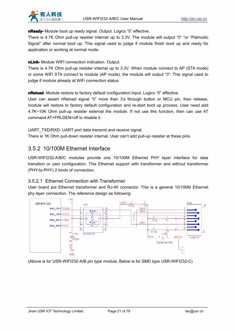
3.5.2 10/100M Ethernet InterfaceUSR-WIFI232-A/B/C modules provide one 10/100M Ethernet PHY layer interface for datatransition or user configuration. This Ethernet support with transformer and without transformer(PHY-to-PHY) 2 kinds of connection.

3.5.2.1 Ethernet Connection with TransformerUser board put Ethernet transformer and RJ-45 connector. This is a general 10/100M Ethernetphy layer connection. The reference design as following:

(Above is for USR-WIFI232-A/B pin type module, Below is for SMD type USR-WIFI232-C)

USR-WIFI232-A/B/C User Manual http://en.usr.cn

Jinan USR IOT Technology Limited Page 22 of 79 [email protected]

Figure 18 EthernetEthernetEthernetEthernet ReferenceReferenceReferenceReference DesignDesignDesignDesign withwithwithwith TransformerTransformerTransformerTransformer

3.5.2.2 Ethernet Connection without TransformerFor this application, Ethernet will work as internal data transmition interface and save onetransformer and RJ45 connector. Ethernet PHY-to-PHY connection will use AC coupledconnection. This is a space and cost optimized solution. Hardware reference design as following:Note: VCC signal at reference design shall base on user board PHY chipset voltage level, suchas 2.5V power supply for general Ethernet PHY chipset.

(Above is for USR-WIFI232-A/B pin type module, Below is for SMD type USR-WIFI232-C)

USR-WIFI232-A/B/C User Manual http://en.usr.cn

Jinan USR IOT Technology Limited Page 23 of 79 [email protected]

Figure 19 EthernetEthernetEthernetEthernet ReferenceReferenceReferenceReference DesignDesignDesignDesign withoutwithoutwithoutwithout TransformerTransformerTransformerTransformer

This module Ethernet interface default is for the application with transformer connection. If youneed PHY-PHY directly connection, please change the hardware as follows:1.1.1.1. WeldWeldWeldWeld 0000 ohmohmohmohm resistanceresistanceresistanceresistance inininin redredredred positionpositionpositionposition2.2.2.2. RemoveRemoveRemoveRemove thethethethe componentcomponentcomponentcomponent inininin yellowyellowyellowyellow positionpositionpositionposition

BOT side component TOP side component

Figure 20 SchematicSchematicSchematicSchematic resistanceresistanceresistanceresistance changeschangeschangeschanges

Specific PHY-PHY direct connection reference to user manual chapter 1.3.2.2 application ofEthernet without transformer and AT+FEPTP commandThe command:AT+FVEW=enable<CR> to open ethernet WAN port functionRemark:1. Only when ethernet as WAN, this command is needed. Module default LAN port.2. After this command, make sure module WAN IP and LAN IP in different segment. (Modify theALN IP in AP Settings, modify the WAN IP in STA Settings)

AT+FEPTP=on<CR> Quey/set default ethernet PHY-PHY on/offAT+FEPHY=on<CR> Open ethernet function permanentlyAT+RELD<CR> Command with “F” need to be affective after AT+RELD

After module reset, command effect, then will not impact by ReloadFor user’s design, pls note:1. Cable connection should be AC coupling, your cable need be pulled up to VCC (fit with PHYchip level)2. Cable TX connected to RX. In PHY-PHY direct connection, PHY chip dose not supportdirect/ cross self-adaption3.Your PHY chip on board should better to be forced into 100M work mode

USR-WIFI232-A/B/C User Manual http://en.usr.cn

Jinan USR IOT Technology Limited Page 24 of 79 [email protected]

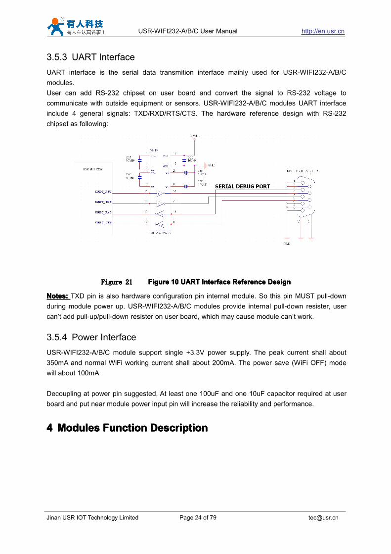
3.5.3 UART InterfaceUART interface is the serial data transmition interface mainly used for USR-WIFI232-A/B/Cmodules.User can add RS-232 chipset on user board and convert the signal to RS-232 voltage tocommunicate with outside equipment or sensors. USR-WIFI232-A/B/C modules UART interfaceinclude 4 general signals: TXD/RXD/RTS/CTS. The hardware reference design with RS-232chipset as following:

Figure 21 FigureFigureFigureFigure 10101010 UARTUARTUARTUART InterfaceInterfaceInterfaceInterface ReferenceReferenceReferenceReference DesignDesignDesignDesign

Notes:Notes:Notes:Notes: TXD pin is also hardware configuration pin internal module. So this pin MUST pull-downduring module power up. USR-WIFI232-A/B/C modules provide internal pull-down resister, usercan’t add pull-up/pull-down resister on user board, which may cause module can’t work.

3.5.4 Power InterfaceUSR-WIFI232-A/B/C module support single +3.3V power supply. The peak current shall about350mA and normal WiFi working current shall about 200mA. The power save (WiFi OFF) modewill about 100mA

Decoupling at power pin suggested, At least one 100uF and one 10uF capacitor required at userboard and put near module power input pin will increase the reliability and performance.

4444 ModulesModulesModulesModules FFFFunctionunctionunctionunction DDDDescriptionescriptionescriptionescription

USR-WIFI232-A/B/C User Manual http://en.usr.cn

Jinan USR IOT Technology Limited Page 25 of 79 [email protected]

4.14.14.14.1 UserUserUserUser configurationconfigurationconfigurationconfiguration processprocessprocessprocess

After USR-WIFI232-A/B/C module electric starter, based on user pre-set parameters,automatically connect to wireless networks and servers, and enter the working mode is set toopen in accordance with the default serial port parameters.

The parameters which need to configure include:

� Wireless Network Parameters� Wireless Network Name(SSID)

� Security Mode� Encryption Key

� TCP/UDP Linking Parameters� Protocol Type� Link Type(Server or Client)� Target Port ID Number� Target Port IP Address

� Serial Port Parameters� Baud Rate� Data Bit� Parity (Check) Bit� Stop Bit� Hardware Flow Control

� Work Mode Selection� Transparent transmission/Serial command mode/GPIO1 mode/GPIO2 mode

The following sections will introduce specific to each part in detail.

4.24.24.24.2 WorkingWorkingWorkingWorking modemodemodemode

4.2.1 Transparent Transmission ModeUSR-WIFI232-A/B/C modules support serial interface transparent transmission mode. The benefitof this mode is achieves a plug and play serial data port, and reduces user complexity furthest. Inthis mode, user should only configure the necessary parameters. After power on, module canautomatically connect to the default wireless network and server.

As in this mode, the module's serial port always work in the transparent transmission mode, sousers only need to think of it as a virtual serial cable, and send and receive data as using asimple serial. In other words, the serial cable of users’ original serial devices is directly replacedwith the module; user devices can be easy for wireless data transmission without any changes.

USR-WIFI232-A/B/C User Manual http://en.usr.cn

Jinan USR IOT Technology Limited Page 26 of 79 [email protected]

The transparent transmission mode can fully compatible with user’s original software platformand reduce the software development effort for integrate wireless data transmission.

Notes:Notes:Notes:Notes: Users also open the serial port hardware flow control (CTS/RTS) function, so that we canmake the bit error rate to a minimum.If the user doesn't need hardware flow control function of theserial port, only need to the corresponding pin foot (CTS/RTS) hung up.

4.2.2 Serial command modeIn this mode, the user can send the serial data to a different server address, this pattern can beuse udp or TCP client sends data to the server.Customer MCU send packets according to the following format, parsing module is finished, onlythe n bytes of data sent to the destination address.When data is returned, not analytical data fromserial port output directly.

Table 8 Protocol table of Serial command modeframeheader

length function

byte

Backupdata area

Destination port

Targetaddress

Data Sumcheck

2 2(n+m+5)

1 2 2 m n 1

frameframeframeframe headerheaderheaderheader:0x55 0xAA(Constant)

LengthLengthLengthLength:Starting from the function byte, to Sum check (does not contain the sum check) all bytes.

High byte at the frontFunctionFunctionFunctionFunction bytebytebytebyte:

Bit0:(UDP:0 ;TCP:1)Bit1:(Short connection:0;Long connection:1)Bit2:(IP:0;Domain name:1)Bit7:(cut protocol:0;full protocol:1)Note: currently only supports cut protocol

Notes:� Bit1:If it is a short connection, it sends data, and then will be disconnected; if it is long

connection, it sends data, connection will remain, until the re changing the target address.� Bit2:Indicates that the target address is IP or domain name. If it is IP, the target address is 4

bytes; if the domain name, the target address length for the entire domain name string length(the last byte address is ‘\0’, that is the end of the string).

� Bit7:Under the cut protocol, reply frame contains only data; Under the full protocol, replyframe has "failed to send", "waiting for", "UDP radio response equipment IP" frame data.

BackupBackupBackupBackup datadatadatadata areaareaareaarea::::� First byte:If it is a short connection, this position is TCP waits for the timeout time (1-255), if

the send command is completed, did not receive a response, then wait a few seconds andthe corresponding, if 5, said to wait for the 5S to disconnect; if the sending command,immediately receive the returned data, then immediately disconnected; if it is long connection,this position is 0x00.

� Second byte:Reserve

USR-WIFI232-A/B/C User Manual http://en.usr.cn

Jinan USR IOT Technology Limited Page 27 of 79 [email protected]

DestinationDestinationDestinationDestination portportportport::::Little endian, low byte in the former,such as port 23, here are 0x17 0x00

TargetTargetTargetTarget address:address:address:address:If it is IP, is 4 bytes, for example, 192.168.0.7 said 0x07 0x00 0xA8 0xC0; if it is a domain

name, then the address of indefinite length,ending with the’\0'.Data:Data:Data:Data:

Variable length,the maximum not exceeding 1000bytes.SumSumSumSum check:check:check:check:

From the function word to check byte (does not contain a check byte), add Sum check.The following is an example of a specific application:

send data:0x55 0xaa 0x00 0x0a 0x00 0x00 0x00 0x21 0x00 0x85 0x00 0xA8 0xC0 0x01 0x0fLength:0x00 0x0aFunction byte:0x00 (UDP;Short connection;IP;cut protocol)Destination port:0x21 0x00(33)Target address:0x85 0x00 0xA8 0xC0 (192.168.0.133)Data:0x01(data length :1)Sum check:0x0f (0x00+0x00+0x00+0x21+0x00+0x85+0x00+0xA8+0xC0+0x01=0x0f)

4.2.3 GPIO 1 mode/GPIO 2 modeUSR-WIFI232-A/B/C module support 2 GPIO mode: GPIO-1 and GPIO-2. At GPIO-1 mode,UART (TXD/ RXD/CTS/RTS) defined as GPIO and others (nReady/nLink/nReload) defined asfunctional pin. At GPIO-2, all these 7 pins defined as GPIO. So, GPIO mode not supports UARTcommunication.When module works at GPIO mode, PC and other equipments can setup connection (TCP/UDP)through WiFi, then read/write GPIO information through command.� GPIO n IN, Set GPIOn as input, Response GPIO OK or GPIO NOK;� GPIO n OUT 0, Set GPIOn as output and output ‘0’, Response GPIO OK or GPIO NOK;� GPIO n OUT 1, Set GPIOn as output and output ‘1’, Response GPIO OK or GPIO NOK;� GPIO n SW, Set GPIOn as output and switch the output status, Response GPIO OK or

GPIO NOK;� GPIO n PWM m1 m2, Set GPIOn output a wave: m1 is ‘high’ duration and m2 is ’low’

duration (Time unit is ‘ms’ and minimal is 10ms), Response GPIO OK or GPIO NOK;� GPIO n GET, Read GPIOn status, Response I0,I1,O0,O1, means ” input low ” , ” input

high”,”output low”,”output high”Notes: n can be 3, 4, 5, 6, 8, 9, 10 corresponding module pin. GPIO 4 and 10 can only defined asinput and GPIO 3 can only defined as output.GPIO READ returns all current IO status, and GPIO n GET said method. Such as, I1I1I0I0I0I0O1,I said input, O output. 0 low, 1 express high.4 and 10 of the two pin is negated. Read the 1 actual0 actual 1, read the 0.

4.34.34.34.3 WirelessWirelessWirelessWireless NetworkingNetworkingNetworkingNetworking

USR-WIFI232-A/B/C module can be configured as both wireless STA and AP base on networktype. Logically there are two interfaces in USR-WIFI232-A/B/C. One is for STA, and another is for

USR-WIFI232-A/B/C User Manual http://en.usr.cn

Jinan USR IOT Technology Limited Page 28 of 79 [email protected]

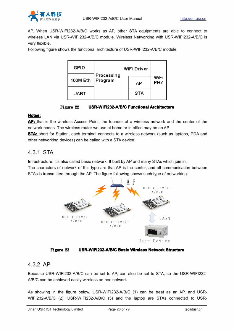
AP. When USR-WIFI232-A/B/C works as AP, other STA equipments are able to connect towireless LAN via USR-WIFI232-A/B/C module. Wireless Networking with USR-WIFI232-A/B/C isvery flexible.Following figure shows the functional architecture of USR-WIFI232-A/B/C module:

Figure 22 USR-WIFI232-A/B/CUSR-WIFI232-A/B/CUSR-WIFI232-A/B/CUSR-WIFI232-A/B/C FunctionalFunctionalFunctionalFunctional ArchitectureArchitectureArchitectureArchitecture

Notes:Notes:Notes:Notes:AP:AP:AP:AP: that is the wireless Access Point, the founder of a wireless network and the center of thenetwork nodes. The wireless router we use at home or in office may be an AP.STA:STA:STA:STA: short for Station, each terminal connects to a wireless network (such as laptops, PDA andother networking devices) can be called with a STA device.

4.3.1 STAInfrastructure: it’s also called basic network. It built by AP and many STAs which join in.The characters of network of this type are that AP is the center, and all communication betweenSTAs is transmitted through the AP. The figure following shows such type of networking.

A P

U S R - W I F I 2 3 2 -A / B / C U S R - W I F I 2 3 2 -

A / B / C

U S R - W I F I 2 3 2 -A / B / C

U A R T

U s e r D e v i c e

Figure 23 USR-WIFI232-A/B/CUSR-WIFI232-A/B/CUSR-WIFI232-A/B/CUSR-WIFI232-A/B/C BasicBasicBasicBasic WirelessWirelessWirelessWireless NetworkNetworkNetworkNetwork StructureStructureStructureStructure

4.3.2 APBecause USR-WIFI232-A/B/C can be set to AP, can also be set to STA, so the USR-WIFI232-A/B/C can be achieved easily wireless ad hoc network.

As showing in the figure below, USR-WIFI232-A/B/C (1) can be treat as an AP, and USR-WIFI232-A/B/C (2), USR-WIFI232-A/B/C (3) and the laptop are STAs connected to USR-

USR-WIFI232-A/B/C User Manual http://en.usr.cn

Jinan USR IOT Technology Limited Page 29 of 79 [email protected]

WIFI232-A/B/C (1). Meanwhile, all USR-WIFI232-A/B/C modules can connected to user devicevia UART interface. All USR-WIFI232-A/B/C modules can be operated and managed through thelaptop. So it is convenient to O&M all USR-WIFI232-A/B/C modules. Moreover, in such Adhocnetwork structure, the whole coverage of a wireless network can be extended easily.

P C

U S R -W I F I 2 3 2 -A/B/C

User Device

U A R T

U S R -W I F I 2 3 2 -A/B/CU S R -W I F I 2 3 2 -A/B/C

U A R T

User Device

Figure 24 USR-WIFI232-A/B/CUSR-WIFI232-A/B/CUSR-WIFI232-A/B/CUSR-WIFI232-A/B/C STASTASTASTANetworkNetworkNetworkNetwork StructureStructureStructureStructure

4.3.3 AP+STAUSR-WIFI232-A/B/C module support AP+STA network mode, means module support one APinterface and one STA interface at the same time, as following figure,

A P

User Device

U A R TPhone

U S R -W I F I 2 3 2 -A/B/C

T c p Client

T c p server

Tcp serverT c p b

Figure 25 USR-WIFI232-A/B/CUSR-WIFI232-A/B/CUSR-WIFI232-A/B/CUSR-WIFI232-A/B/C AP+STAAP+STAAP+STAAP+STANetworkNetworkNetworkNetwork StructureStructureStructureStructure

When module enables AP+STA function, Module’s STA interface can connect with router andconnect to TCP server in the network. At the same time, module’s AP interface is also active and

USR-WIFI232-A/B/C User Manual http://en.usr.cn

Jinan USR IOT Technology Limited Page 30 of 79 [email protected]

permit phone/PAD to connect through TCPB, then phone/PAD can control user device and andsetting the module parameters,The advantage of AP+STA mode is:� Users can easily setting and track user device through Phone/PAD and not change the

orginal network setting.� Users can easily setting module’s parameters through WiFi when module works as STA

mode.AP+STAAP+STAAP+STAAP+STAModeModeModeMode Setting:Setting:Setting:Setting:AP+STA mode need serial AT command to enable as follows:� AT+FAPSTA=on, Enable AP+STA mode;� Then, when you configure module works as STA mode, it’s AP interface still active;AP+STAAP+STAAP+STAAP+STAModeModeModeMode Notes:Notes:Notes:Notes:When user enable AT+STA function,the STA port need to keep connected with otherrouter(AP),or STA port will have to scan the AP frequently ,which will affect AP port function and may causesome date loss.So ,if user confirm STA port can't connect with AP at some time,user can disable the STA scanthrough the following command:� AT+STTC=on/off,on:Scan AP;off:No Scan AP.After re-start module,this command not saved;� AT+FSTTC=on/off;This command is saved after re-staring the module;

4.44.44.44.4 EthernetEthernetEthernetEthernet InterfaceInterfaceInterfaceInterface CommunicationCommunicationCommunicationCommunication

USR-WIFI232-A/B/C module provides one 100M Ethernet interface. With this Ethernet interface,user can easily realize the three interface (WiFi, UART, and Ethernet) intercommunication andnetworking. USR-WIFI232-A/B/C module can configured as Bridge Mode or Router Mode baseon different networking technology.

Notes: As the Ethernet mode will increase additional consumption, so it is default closed. If youneed this function, pls use AT+FEPHY=on to open it and RELD can’t change this. For differentapplication, USR-WIFI232-610 need version switch via commands (such as following descriptionof N-ver and Z-ver). With command AT+FVER=n to switch to N-ver and with commandAT+FVER=z to switch to Z-ver.

4.4.1 USR-WIFI232-A/B/C Ethernet Interface Networking (As AP)

USR-WIFI232-A/B/C User Manual http://en.usr.cn

Jinan USR IOT Technology Limited Page 31 of 79 [email protected]

P C 1 P C 2U S R -W I F I 2 3 2 -A/B/C

I P :1 0 .1 0 .1 0 0 .1 0 1GateWay :

1 0 .1 0 .1 0 0 .2 5 4

A PI P :1 0 .1 0 .1 0 0 .2 5 4

I P :1 0 .1 0 .1 0 0 .1 0 0GateWay :

1 0 .1 0 .1 0 0 .2 5 4

1 0 0 M Eth

Figure 26 USR-WIFI232-A/B/CUSR-WIFI232-A/B/CUSR-WIFI232-A/B/CUSR-WIFI232-A/B/C EthernetEthernetEthernetEthernet InterfaceInterfaceInterfaceInterface NetworkingNetworkingNetworkingNetworking (As(As(As(As AP)AP)AP)AP)

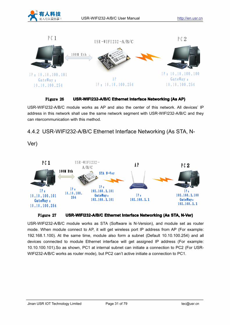
USR-WIFI232-A/B/C module works as AP and also the center of this network. All devices’ IPaddress in this network shall use the same network segment with USR-WIFI232-A/B/C and theycan ntercommunication with this method.

4.4.2 USR-WIFI232-A/B/C Ethernet Interface Networking (As STA, N-

Ver)

P C 1 U S R -W I F I 2 3 2 -A/B/C

A P P C 2

I P :1 0 .1 0 .1 0 0 .1 0 1

GateWay :1 0 .1 0 .1 0 0 .2 5 4

I P :1 0 .1 0 .1 0 0 .

2 5 4

I P :1 9 2 .1 6 8 .1.1 0 1

GateWay:1 9 2 .1 6 8 .1.1 0 1

I P :1 9 2 .1 6 8 .1.1

I P :1 9 2 .1 6 8 .1.1 0 0

GateWay:1 9 2 .1 6 8 .1.1

1 0 0 M EthSTA N -V e r

Figure 27 USR-WIFI232-A/B/CUSR-WIFI232-A/B/CUSR-WIFI232-A/B/CUSR-WIFI232-A/B/C EthernetEthernetEthernetEthernet InterfaceInterfaceInterfaceInterface NetworkingNetworkingNetworkingNetworking (As(As(As(As STASTASTASTA,,,, N-VerN-VerN-VerN-Ver))))

USR-WIFI232-A/B/C module works as STA (Software is N-Version), and module set as routermode. When module connect to AP, it will get wireless port IP address from AP (For example:192.168.1.100). At the same time, module also form a subnet (Default 10.10.100.254) and alldevices connected to module Ethernet interface will get assigned IP address (For example:10.10.100.101).So as shown, PC1 at internal subnet can initiate a connection to PC2 (For USR-WIFI232-A/B/C works as router mode), but PC2 can’t active initiate a connection to PC1.

USR-WIFI232-A/B/C User Manual http://en.usr.cn

Jinan USR IOT Technology Limited Page 32 of 79 [email protected]

4.4.3 USR-WIFI232-A/B/C Ethernet Interface Networking (As STA, Z-Ver)

P C 1 U S R -W I F I 2 3 2 -A/B/C A P P C 2

I P :1 9 2 .1 6 8 .1.1 0 1GateWay:

1 9 2 .1 6 8 .1.1

I P :1 9 2 .1 6 8 .1.1 0GateWay:

1 9 2 .1 6 8 .1.1I P :

1 9 2 .1 6 8 .1.1

I P :1 9 2 .1 6 8 .1.1 0 0GateWay:

1 9 2 .1 6 8 .1.1

1 0 0 M EthSTA Z-V e r

Figure 28 USR-WIFI232-A/B/CUSR-WIFI232-A/B/CUSR-WIFI232-A/B/CUSR-WIFI232-A/B/C EthernetEthernetEthernetEthernet InterfaceInterfaceInterfaceInterface NetworkingNetworkingNetworkingNetworking (As(As(As(As STASTASTASTA,,,, Z-VerZ-VerZ-VerZ-Ver))))

For above networking, USR-WIFI232-A/B/C module works as STA(Firmware is Z-Version),andmodule configured as bridge mode. When module connect to AP, all devices connected tomodule Ethernet interface will get assigned IP address from AP (For example: 192.168.1.101).Formodule works as bridge mode, it can be treated as a transparent device and PC1, PC2 cancommunicate without any limit. But in this networking, USR-WIFI232-A/B/C module needs assigna static LAN IP address (For example: 192.168.1.10) if module also needs communication withAP or configuration through web page.

4.54.54.54.5 WI-FIWI-FIWI-FIWI-FI parameterparameterparameterparameter settingsettingsettingsetting

4.5.1 Auto- Frequency FunctionWhen module works as STA, USR-WIFI232-A/B/C will adjust its wireless channel to keep thesame channel with associated AP and connect in.When module works as AP and USR-WIFI232-A/B/C enable Auto-frequency function, then whenmodule boot up, it will select the best wireless channel based on surrounding environment.

4.5.2 SecurityUSR-WIFI232-A/B/C module supports multiple wireless encryption mechanisms, and enables toprotect the security of user’s data transmission, the mechanisms include:

� WEP� WPA-PSK/TKIP� WPA-PSK/AES� WPA2-PSK/TKIP� WPA2-PSK/AES

USR-WIFI232-A/B/C User Manual http://en.usr.cn

Jinan USR IOT Technology Limited Page 33 of 79 [email protected]

4.5.3 Search Function for STAWhen using web configuration STA Interface Setting Page, user can push “Search” button to findsurrounding AP, and find a AP to associated.

Figure 29 SearchSearchSearchSearch pagepagepagepage

4.5.4 Address BindingUSR-WIFI232-A/B/C module supports the feature of binding the BSSID address of target network.According to the provisions of 802.11 protocol, different wireless networks can have a samenetwork name (i.e. SSID / ESSID), but must correspond to a unique BSSID address (i.e. MACaddress). Illegal intruders can create a wireless network with the same SSID / ESSID, it will makeSTAs in the network to join to the illegal AP, thereby and then network leakage happen.

Users can prevent STA from joining to illegal network by binding the BSSID address, to improvewireless network security.

4.64.64.64.6 UARTUARTUARTUART FrameFrameFrameFrame SchemeSchemeSchemeScheme

4.6.1 UART Free-FrameUSR-WIFI232-A/B/C support UART free-frame function. If user select open this function, modulewill check the intervals between any two bytes when receiving UART data. If this interval timeexceeds defined value (50ms default), USR-WIFI232-A/B/C will think it as the end of one frameand transfer this free-frame to WiFi port, or USR-WIFI232-A/B/C will receive UART data until 4Kbytes, then transfer 4KB frame to WiFi port.

USR-WIFI232-A/B/C’s default interval time is 50ms. User can also set this interval to fast (10ms)through AT command. But user have to consider if user MCU can send UART data with 10msinterval ,or the UART data may be divide as fragment.

USR-WIFI232-A/B/C User Manual http://en.usr.cn

Jinan USR IOT Technology Limited Page 34 of 79 [email protected]

Through AT command: AT+FUARTTE=fast/normal, user can set the interval time: fast (10ms) andnormal (50ms). This command is factory default setting command and AT+RELD can’t change itsvalue.

4.6.2 UART Auto-FrameUSR-WIFI232-A/B/C support UART auto-frame function. If user select open this function andsetting auto-frame trigger length and auto-frame trigger time parameters, then module will autoframing the data which received from UART port and transmitting to the network as pre-defineddata structure.

� Auto-frameAuto-frameAuto-frameAuto-frame triggertriggertriggertrigger length:length:length:length: The fixed data length that module used to transmitting to thenetwork.

� Auto-frameAuto-frameAuto-frameAuto-frame triggertriggertriggertrigger time:time:time:time: After the trigger time, if UART port received data can’t reach auto-frame trigger length, then module will transmitting available data to the network and bypassthe auto-frame trigger length condition.

Detailed UART auto-frame function can refer to AT+ instruction set “UARTF/UARTFT/UARTFL”introduction.

4.74.74.74.7 NetworkNetworkNetworkNetwork SettingSettingSettingSetting

USR-WIFI232-A/B/C module has two TCP/UDP Socket: Socket A and Socket B. Serial datawritten to the module, will be sent to the Socket A and B simultaneously; TCP/UDP data thatmodule receives through either Socket A or B,will be sent to the serial port.Dual Socket through different settings, you can achieve a variety of network interconnect. Whenthe module shipped only open Socket A, Socket B default is not to connect, if the user needs touse, please set by AT commands.

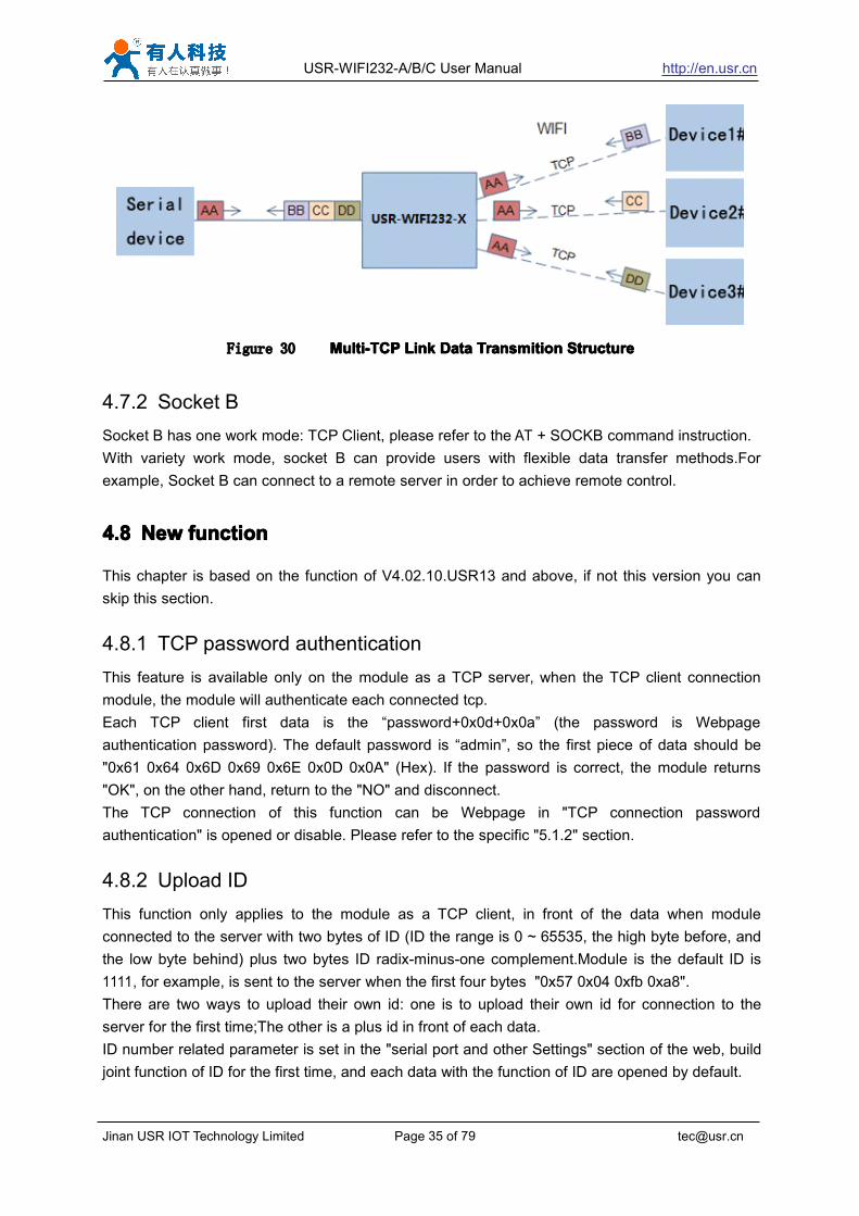
4.7.1 Socket ASocket A has three work mode: TCP Server, TCP Client, UDP.The setting method, please refer tothe AT+NETP command instruction.When Socket A configured as TCP Server, it supports Multi-TCP link connection, and maximum32 TCP clients permitted to connect to Socket A.Multi-TCP link connection will work as following structure:Upstream: All dates from different TCP connection or client will be transmitted to the serial port asa sequence.Downstream: All data from serial port (user) will be duplicate and broadcast to every TCPconnection or client.Detailed multi-TCP link data transmition structure as following figure:

USR-WIFI232-A/B/C User Manual http://en.usr.cn

Jinan USR IOT Technology Limited Page 35 of 79 [email protected]

Figure 30 Multi-TCPMulti-TCPMulti-TCPMulti-TCP LinkLinkLinkLink DataDataDataData TransmitionTransmitionTransmitionTransmition StructureStructureStructureStructure

4.7.2 Socket BSocket B has one work mode: TCP Client, please refer to the AT + SOCKB command instruction.With variety work mode, socket B can provide users with flexible data transfer methods.Forexample, Socket B can connect to a remote server in order to achieve remote control.

4.84.84.84.8 NewNewNewNew functionfunctionfunctionfunction

This chapter is based on the function of V4.02.10.USR13 and above, if not this version you canskip this section.

4.8.1 TCP password authenticationThis feature is available only on the module as a TCP server, when the TCP client connectionmodule, the module will authenticate each connected tcp.Each TCP client first data is the “password+0x0d+0x0a” (the password is Webpageauthentication password). The default password is “admin”, so the first piece of data should be"0x61 0x64 0x6D 0x69 0x6E 0x0D 0x0A" (Hex). If the password is correct, the module returns"OK", on the other hand, return to the "NO" and disconnect.The TCP connection of this function can be Webpage in "TCP connection passwordauthentication" is opened or disable. Please refer to the specific "5.1.2" section.

4.8.2 Upload IDThis function only applies to the module as a TCP client, in front of the data when moduleconnected to the server with two bytes of ID (ID the range is 0 ~ 65535, the high byte before, andthe low byte behind) plus two bytes ID radix-minus-one complement.Module is the default ID is1111, for example, is sent to the server when the first four bytes "0x57 0x04 0xfb 0xa8".There are two ways to upload their own id: one is to upload their own id for connection to theserver for the first time;The other is a plus id in front of each data.ID number related parameter is set in the "serial port and other Settings" section of the web, buildjoint function of ID for the first time, and each data with the function of ID are opened by default.

USR-WIFI232-A/B/C User Manual http://en.usr.cn

Jinan USR IOT Technology Limited Page 36 of 79 [email protected]

ID can also use the at command to set the related parameters, specific refer to 5.2.1.4.32-5.2.1.4.34 section.

4.8.3 Self-adaption BaudrateThis feature, please cooperate with our company's virtual serial port software use.Use a serial port connected module, and use the at command "at + AABR = on" open thisfunction and restart.In the USR - VOCM software "synchronous baud rate (RFC2217 similar)" isselected, the following figure.

Figure 31 RFCRFCRFCRFC 2217221722172217

In this way, the module of baud rate will be as the USR-VCOM to change at any time, and don'thave to restart the module.If restart the module, baud rate and will come back to before.

4.8.4 WEB IOThis function only work for "GPIO2 mode".When the module is in the "GPIO2 mode", enter the Webpage in "WEB IO", you can click on thecorresponding button to control module pin level. Without the need to download and install app,any platform, any equipment, as long as you can into the built-in Webpage of module through thebrowser built-you can control module pin of IO.

4.8.5 KeepaliveV4.02.10. USR13 and above version of the firmware added keepalive when the TCP connectionmechanism, so when the module of network anomalies, timely diagnose abnormal to the networkand disconnect, when the network has resumed after, and just in time to connect to the server.

4.94.94.94.9 PalmodicPalmodicPalmodicPalmodic SignalSignalSignalSignal

Base on selected factory default setting, “nReady” signal can have two output statuses:� Status One: The module will output “0” after normal boot up. This signal used to judge if

module finish boot up and ready for application.� Status Two: The module will output “Palmodic Signal” after normal boot up.The palmodic

signal is 0.5Hz square wave with dutyfactor 1:1. User can query this signal to judge ifmoduleis active “live” or need to re-boot. When module switches to command mode, it willoutput “0”, which used to distinguish work mode and command mode.

Notes:

USR-WIFI232-A/B/C User Manual http://en.usr.cn

Jinan USR IOT Technology Limited Page 37 of 79 [email protected]

This function is user selected factory setting and RELD instruction will not effective for thisfunction. If user not requires this function, the default factory setting is Status One. Contact withUSR Technology for more detailed support.

4.104.104.104.10 ParametersParametersParametersParameters ConfigurationConfigurationConfigurationConfiguration

USR-WIFI232-A/B/C module supports two methods to configuration parameters: WebWebWebWeb AccessingAccessingAccessingAccessingand AT+instructionAT+instructionAT+instructionAT+instruction set.set.set.set.Web accessing means users can configure parameters through built-in webpage. When USR-WIFI232-A/B/C module connected to wireless network, parameters configuration is done on a PCconnected to the same wireless network. AT+instruction set configuration means user configureparameters through serial interface command. Refer to “AT+instruction set” chapter for moredetail.

Notes:Notes:Notes:Notes:USR can customized the parameters setting as customer request and ship USR-WIFI232-A/B/Cmodules with these parameters as factory default configuration. It will reduce user’s moduleconfiguration time for mass production. Also, if user need different parameters setting for everymodule, USR can provide the auto-configuration tool to speed up the module configurationduration. Please contact USR technical interface to acquire this tool if required.

4.114.114.114.11 FirmwareFirmwareFirmwareFirmware UpgradeUpgradeUpgradeUpgrade

USR-WIFI232-A/B/C module supports firmware upgrade online.

USR-WIFI232-A/B/C User Manual http://en.usr.cn

Jinan USR IOT Technology Limited Page 38 of 79 [email protected]

5555 WebWebWebWebAccessingAccessingAccessingAccessing andandandand AT+instructionAT+instructionAT+instructionAT+instruction setsetsetset

5.15.15.15.1 ConfigurationConfigurationConfigurationConfiguration viaviaviavia WebWebWebWeb AccessingAccessingAccessingAccessing

When first use USR-WIFI232-A/B/C modules, user may need some configuration. User canconnect to USR-WIFI232-A/B/C module’s wireless interface with following default settinginformation and configure the module through laptop.

Table 9 USR-WIFI232-A/B/C WebAccess Default SettingParametersParametersParametersParameters DefaultDefaultDefaultDefault SettingSettingSettingSettingSSID USR-WIFI232-AP_xxxxIP Address 10.10.100.254Subnet Mask 255.255.255.0User Name adminPassword admin

5.1.1 Open Web Management InterfaceStep 1: Connect laptop to SSID “USR-WIFI232-AP_xxxx” of USR-WIFI232-A/B/C module viawireless LAN card;Step 2: After wireless connection OK. Open Wen browser and access “http://10.10.100.254http://10.10.100.254http://10.10.100.254http://10.10.100.254”;Step 3: Then input user name and password in the page as following and click “OK” button.

Figure 32 OpenOpenOpenOpen WebWebWebWeb ManagementManagementManagementManagement pagepagepagepage

The USR-WIFI232-A/B/C web management page support English and Chinese language. Usercan select language environment at the top right corner and click “Apply” button.

The main menu include five pages: “Mode Selection”,” AP Interface Setting”,”STA InterfaceSetting”,”Application Setting”, “WEB IO”and “Device Management”

USR-WIFI232-A/B/C User Manual http://en.usr.cn

Jinan USR IOT Technology Limited Page 39 of 79 [email protected]

5.1.2 Mode Selection PageThis page use to setting the wireless networking mode (AP and STA mode)."Data transmission mode" selection module working mode are "Transparent Mode", "Serial Commandmode", "GPIO1 mode", "GPIO2 mode"."TCP connection password authentication" can choose whether open TCP password authentication.

Figure 33 ModeModeModeMode SelectionSelectionSelectionSelection PagePagePagePage

5.1.3 AP Interface Setting PageThis page use to setting the parameters when USR-WIFI232-A/B/C module works as AP.

Figure 34 APAPAPAP InterfaceInterfaceInterfaceInterface SettingSettingSettingSetting PagePagePagePage

USR-WIFI232-A/B/C User Manual http://en.usr.cn

Jinan USR IOT Technology Limited Page 40 of 79 [email protected]

5.1.4 STA Interface Setting PageThis page use to setting the parameters when USR-WIFI232-A/B/C module works as STA.Such as SSID of AP which module need to connected, and also select the networking type: DHCP orstatic IP address.

Figure 35 STASTASTASTA InterfaceInterfaceInterfaceInterface SettingSettingSettingSetting PagePagePagePage

5.1.5 Application Setting PageThis page use to setting the parameters of serial port communication, such as UARTsetting,UART AutoFrame Setting,Ethernet function,Device ID setting and high layer networkprotocol setting which used support serial communication.

USR-WIFI232-A/B/C User Manual http://en.usr.cn

Jinan USR IOT Technology Limited Page 41 of 79 [email protected]

Figure 36 ApplicationApplicationApplicationApplication SettingSettingSettingSetting PagePagePagePage

Notes:Notes:Notes:Notes:Generally, Network protocols support three modes: TCPTCPTCPTCP ServerServerServerServer, TCPTCPTCPTCP ClientClientClientClient, andandandand UDPUDPUDPUDP. UDP hasno server and client requirement according to standard.

Besides module working as TCP Server (IP address not required in this mode). User must set theIP address of the device which need communicate with USR-WIFI232-A/B/C module.Also the Port ID between two sides of the communication devices must keep the same.

5.1.6 WEB IO

USR-WIFI232-A/B/C User Manual http://en.usr.cn

Jinan USR IOT Technology Limited Page 42 of 79 [email protected]

Figure 37 WEBWEBWEBWEB IOIOIOIO PagePagePagePage

5.1.7 Device Management PageThis page use to manage USR-WIFI232-A/B/C module general setting, such as administrator setting,restart module button, restore factory default setting button, and update firmware through webpage.

USR-WIFI232-A/B/C User Manual http://en.usr.cn

Jinan USR IOT Technology Limited Page 43 of 79 [email protected]

Figure 38 DeviceDeviceDeviceDevice ManagementManagementManagementManagement PagePagePagePage

Notes:Notes:Notes:Notes:

Figure 39 Restart module button: When you setting the parameters of different web pages,you will click “Apply” button to confirm the setting, but the setting take effect only after user click

the “Restart” button here, the module will re-boot up and refresh the memory information with newchanges.

5.25.25.25.2 AT+instructionAT+instructionAT+instructionAT+instruction IntroductionIntroductionIntroductionIntroduction

5.2.1 Configuration ModeWhen USR-WIFI232-A/B/C power up, it will default works as transparent transmission mode, thenuser can switch to configuration mode by serial port command. USR-WIFI232-A/B/C UARTdefault parameters setting as below figure

Figure 40 USR-WIFI232-A/B/CUSR-WIFI232-A/B/CUSR-WIFI232-A/B/CUSR-WIFI232-A/B/C DefaultDefaultDefaultDefault UARTUARTUARTUART PortPortPortPort ParametersParametersParametersParameters

USR-WIFI232-A/B/C User Manual http://en.usr.cn

Jinan USR IOT Technology Limited Page 44 of 79 [email protected]

In configuration mode, user can setting the module through AT+ instruction set, which cover allweb page setting function.

5.2.1.1 Switch to Configuration ModeTwo steps to finish switching from transparent transmission mode to configuration mode.

���� UARTUARTUARTUART inputinputinputinput ““““++++++++++++””””,,,, afterafterafterafter modulemodulemodulemodule receivereceivereceivereceive ““““++++++++++++””””,,,, andandandand feedbackfeedbackfeedbackfeedback ““““aaaa”””” asasasas confirmation.confirmation.confirmation.confirmation.���� UARTUARTUARTUART inputinputinputinput ““““aaaa””””,,,, afterafterafterafter modulemodulemodulemodule receivereceivereceivereceive ““““aaaa”””” andandandand feedbackfeedbackfeedbackfeedback ““““+ok+ok+ok+ok”””” totototo gogogogo intointointointo AT+AT+AT+AT+

instructioninstructioninstructioninstruction setsetsetset configurationconfigurationconfigurationconfiguration mode.mode.mode.mode.

Figure 41 SwitchSwitchSwitchSwitch totototo ConfigurationConfigurationConfigurationConfiguration ModeModeModeMode

Notes:Notes:Notes:Notes:1. When user input “+++” (No “Enter” key required), the UART port will display feedbackinformation “a”, and not display input information”+++” as above UART display.2. Any other input or wro ng step to UART port will cause the module still works as original mode(transparent transmission).

5.2.2 AT+ Instruction Set OverviewUser can input AT+ Instruction through hyper terminal or other serial debug terminal, also canprogram the AT+ Instruction to script. User can also input “AT+H” to list all AT+ Instruction anddescription to start.

USR-WIFI232-A/B/C User Manual http://en.usr.cn

Jinan USR IOT Technology Limited Page 45 of 79 [email protected]

Figure 42 ””””AT+HAT+HAT+HAT+H”””” InstructionInstructionInstructionInstruction forforforfor HelpHelpHelpHelp

We supply software USR-WIFI232-Setup to send command easily, software setup:

Figure 43 SerialSerialSerialSerial portportportport parameterparameterparameterparameter

Click “Open Com”, send “+++a”, it will reply +ok in left side, then type in and send the commandyou need to send, then click “AT+RELD” to restore, then parameters saved.

USR-WIFI232-A/B/C User Manual http://en.usr.cn

Jinan USR IOT Technology Limited Page 46 of 79 [email protected]

Figure 44 softwaresoftwaresoftwaresoftware ofofofof USR-WIFI232-SetupUSR-WIFI232-SetupUSR-WIFI232-SetupUSR-WIFI232-Setup

Above is by COM, also you can send by WIFI:First, connect with PC, open the software, see Net part

Figure 45 SearchSearchSearchSearch modulemodulemodulemodule

Click search, then will show module, click module then you can send command.

5.2.2.1 Instruction Syntax FormatAT+Instruction protocol is based on the instruction of ASCII command style, the description ofsyntax format as follow.

���� FormatFormatFormatFormat DescriptionDescriptionDescriptionDescription� < >: Means the parts must be included� [ ]: Means the optional part

���� CommandCommandCommandCommand MessageMessageMessageMessage

USR-WIFI232-A/B/C User Manual http://en.usr.cn

Jinan USR IOT Technology Limited Page 47 of 79 [email protected]

AT+<CMD>[op][para-1,para-2,para-3,para-4AT+<CMD>[op][para-1,para-2,para-3,para-4AT+<CMD>[op][para-1,para-2,para-3,para-4AT+<CMD>[op][para-1,para-2,para-3,para-4…………]<CR>]<CR>]<CR>]<CR>

� AT+: Prefix of command message;� CMD: Command string;� [op]: Symbol of command operator,

� “=” : The command requires parameters input;� “NULL”: Query the current command parameters setting;

� [para-n]: Parameters input for setting if required;<CR>: ”Enter” Key, it’s 0x0a or 0x0d in ASCII;

NotesNotesNotesNotes: When input AT+Instruction, “AT+<CMD>” character will display capital letter automaticand other parts will not change as you input.

���� ResponseResponseResponseResponse MessageMessageMessageMessage

+<RSP>[op]+<RSP>[op]+<RSP>[op]+<RSP>[op] [para-1,para-2,para-3,para-4[para-1,para-2,para-3,para-4[para-1,para-2,para-3,para-4[para-1,para-2,para-3,para-4…………]<CR><LF><CR><LF>]<CR><LF><CR><LF>]<CR><LF><CR><LF>]<CR><LF><CR><LF>

� +: Prefix of response message;� RSP: Response string;

� “ok” : Success� “ERR”: Failure

� [op] : =� [para-n]: Parameters if query command or Error code when error happened;� <CR>: ASCII 0x0d;� <LF>: ASCIII 0x0a;

���� ErrorErrorErrorError CodeCodeCodeCodeTable 10 Error Code Description USR-WIFI232-A/B/C WebAccess Default Setting

ErrorErrorErrorError CodeCodeCodeCode DescriptionDescriptionDescriptionDescription-1 Invalid Command Format-2 Invalid Command-3 Invalid Operation Symbol-4 Invalid Parameter-5 Operation Not Permitted

5.2.2.2 AT+ Instruction SetTable 11 AT+ Instruction Set List

InstructionInstructionInstructionInstruction DescriptionDescriptionDescriptionDescription<null> NULLE Open/Close show back functionENTM Set module into transparent transmission modeNETP Set/Query network protocol parametersUART Set/Query serial port parametersUARTF Open/Close UART auto-frame functionUARTFT Set/Query UART auto-frame trigger time

USR-WIFI232-A/B/C User Manual http://en.usr.cn

Jinan USR IOT Technology Limited Page 48 of 79 [email protected]

UARTFL Set/Query UART auto-frame trigger lengthTMODE Set/Query data transmission mode

(transparent transmission or agreement transmission)WMODE Set/Query WIFI work mode (AP or STA)WSKEY Set/Query WIFI security parameters as STAWSSSID Set/Query WIFI target AP SSID parameters as STAWSLK Query WiFi link status as STAWEBU Set/Query WEB page login parameters

(User Name and Password)WAP Set/Query WIFI parameters as APWAKEY Set/Query WIFI security parameters as APHIDESSID Set/Query hide AP’s SSIDMSLP Set modules into power save mode.(Turn OFF WiFi)WSCAN Seek AP when module works as STA modeTCPLK Query if TCP link already build-upTCPDIS Open/Cose TCP (Only TCP Client available)WANN Set/Query WAN setting, only effective as STA modeLANN Set/Query LAN setting, only effective as AP modeDHCPDEN Enable/Disable LAN DHCP server functionDHCPGW Set/Query DHCP gateway addressTCPTO Set/Query TCP timeoutMAXSK Set/Query maxima TCP connectionTCPB Open/Close TCPB functionTCPPTB Set/Query TCPB port numberTCPADDB Set/Query TCPB server addressTCPTOB Set/Query TCPB time out timeTCPLKB Query TCPB link statusEPHY Open/Close ETH interfaceSTTC Enable/Disable STA port scan functionDOMAIN Set/Query domain of module webpageFRLDEN Enable/Disable nReload pin functionRELD Restore to factory default settingFUDLX Open / close the 485 functionMMID Device IDIDFIR Send an ID when module connection is establishedIDEVE Every time to send data to send IDAABR Open / close baud rate adaptive functionMID Query module ID informationVER Query module software version informationH Help

Notes:Notes:Notes:Notes: USR-WIFI232-A/B/C module can works as AP or STA, user have to use different AT+Instruction to set WiFi parameters when module works as AP or STA mode.5.2.2.2.15.2.2.2.15.2.2.2.15.2.2.2.1 AT+EAT+EAT+EAT+E

� Function: Open/Close show back function;� Format:

AT+E<CR>AT+E<CR>AT+E<CR>AT+E<CR>+ok<CR><+ok<CR><+ok<CR><+ok<CR>< LFLFLFLF ><CR><><CR><><CR><><CR>< LFLFLFLF >>>>

USR-WIFI232-A/B/C User Manual http://en.usr.cn

Jinan USR IOT Technology Limited Page 49 of 79 [email protected]

When USR-WIFI232-A/B/C module firstly switch from transparent transmission to configuration mode,show back status is open, input “AT+E” to close show back function, input“AT+E” again to open showback function.5.2.2.2.25.2.2.2.25.2.2.2.25.2.2.2.2 AT+ENTMAT+ENTMAT+ENTMAT+ENTM

� Function: Set module into transparent transmission mode;� Format:

AT+ENTM<CR>AT+ENTM<CR>AT+ENTM<CR>AT+ENTM<CR>+ok<CR><+ok<CR><+ok<CR><+ok<CR>< LFLFLFLF ><CR><><CR><><CR><><CR>< LFLFLFLF >>>>

When operate this command, module switch from configuration mode to transparent transmissionmode.5.2.2.2.35.2.2.2.35.2.2.2.35.2.2.2.3 AT+NETPAT+NETPAT+NETPAT+NETP

� Function: Set/Query network protocol parameters;� Format:

� Query OperationAT+NETP<CR>AT+NETP<CR>AT+NETP<CR>AT+NETP<CR>+ok=<protocol,CS,port,IP><CR><+ok=<protocol,CS,port,IP><CR><+ok=<protocol,CS,port,IP><CR><+ok=<protocol,CS,port,IP><CR>< LFLFLFLF ><CR><><CR><><CR><><CR>< LFLFLFLF >>>>� Set Operation

AT+NETP=<protocol,CS,port,IP><CR>AT+NETP=<protocol,CS,port,IP><CR>AT+NETP=<protocol,CS,port,IP><CR>AT+NETP=<protocol,CS,port,IP><CR>+ok<CR><+ok<CR><+ok<CR><+ok<CR>< LFLFLFLF ><CR><><CR><><CR><><CR>< LFLFLFLF >>>>� Parameters:

� protocol:� TCP� UDP

� CS: Network mode:� SERVER� CLIENT

� Port: protocol port ID: Decimal digit and less than 65535� IP: Server’s IP address when module set as client

After USR-WIFI232-A/B/C module boots up again, the setting will be effective.5.2.2.2.45.2.2.2.45.2.2.2.45.2.2.2.4 AT+UARTAT+UARTAT+UARTAT+UART

� Function: Set/Query serial port parameters;� Format:

� Query Operation

AT+UART<CR>AT+UART<CR>AT+UART<CR>AT+UART<CR>+ok=<baudrate,data_bits,stop_bit,parity,flowctrl><CR><+ok=<baudrate,data_bits,stop_bit,parity,flowctrl><CR><+ok=<baudrate,data_bits,stop_bit,parity,flowctrl><CR><+ok=<baudrate,data_bits,stop_bit,parity,flowctrl><CR>< LFLFLFLF ><CR><><CR><><CR><><CR>< LFLFLFLF >>>>� Set Operation

AT+UART=<baudrate,data_bits,stop_bit,parity,flowctrl><CR>AT+UART=<baudrate,data_bits,stop_bit,parity,flowctrl><CR>AT+UART=<baudrate,data_bits,stop_bit,parity,flowctrl><CR>AT+UART=<baudrate,data_bits,stop_bit,parity,flowctrl><CR>+ok<CR><+ok<CR><+ok<CR><+ok<CR>< LFLFLFLF ><CR><><CR><><CR><><CR>< LFLFLFLF >>>>

� Parameters:� baudrate:

USR-WIFI232-A/B/C User Manual http://en.usr.cn

Jinan USR IOT Technology Limited Page 50 of 79 [email protected]

� 50,75,110,134,150,200,300,600,1200,1800,2400,4800,9600,19200,38400,57600,115200,230400,345600,460800

� data_bits:� 5,6,7,8

� stop_bits:� 1,2

� parity:� NONE,EVEN,ODD,MARK,SPACE

� flowctrl:hardware flow control (CTSRTS)� NFC: No flow control� FC: flow control

After USR-WIFI232-A/B/C module boots up again, the setting will be effective.5.2.2.2.55.2.2.2.55.2.2.2.55.2.2.2.5 AT+AT+AT+AT+ UARTFUARTFUARTFUARTF

� Function: Open/Close UART auto-frame function;� Format:

� Query OperationAT+AT+AT+AT+ UARTF<CR>UARTF<CR>UARTF<CR>UARTF<CR>+ok=<para><CR><+ok=<para><CR><+ok=<para><CR><+ok=<para><CR>< LFLFLFLF ><CR><><CR><><CR><><CR>< LFLFLFLF >>>>� Set Operation

AT+AT+AT+AT+ UARTF=<paraUARTF=<paraUARTF=<paraUARTF=<para ><CR>><CR>><CR>><CR>+ok<CR><+ok<CR><+ok<CR><+ok<CR>< LFLFLFLF ><CR><><CR><><CR><><CR>< LFLFLFLF >>>>� Parameters:

� para:� disable - Close auto-frame function;� enable - Open auto-frame function;

5.2.2.2.65.2.2.2.65.2.2.2.65.2.2.2.6 AT+AT+AT+AT+ UARTFTUARTFTUARTFTUARTFT� Function: Set/Query UART auto-frame trigger time;� Format:

� Query OperationAT+AT+AT+AT+ UARTFT<CR>UARTFT<CR>UARTFT<CR>UARTFT<CR>+ok=<time><CR><+ok=<time><CR><+ok=<time><CR><+ok=<time><CR>< LFLFLFLF ><CR><><CR><><CR><><CR>< LFLFLFLF >>>>� Set Operation

AT+AT+AT+AT+ UARTFT=<timeUARTFT=<timeUARTFT=<timeUARTFT=<time ><CR>><CR>><CR>><CR>+ok<CR><+ok<CR><+ok<CR><+ok<CR>< LFLFLFLF ><CR><><CR><><CR><><CR>< LFLFLFLF >>>>� Parameters:

� time: Range 100 ~10000; Unit: ms. Auto-frame trigger time5.2.2.2.75.2.2.2.75.2.2.2.75.2.2.2.7 AT+AT+AT+AT+ UARTFLUARTFLUARTFLUARTFL

� Function: Set/Query UART auto-frame trigger length;� Format:

� Query OperationAT+AT+AT+AT+ UARTFL<CR>UARTFL<CR>UARTFL<CR>UARTFL<CR>+ok=<len><CR><+ok=<len><CR><+ok=<len><CR><+ok=<len><CR>< LFLFLFLF ><CR><><CR><><CR><><CR>< LFLFLFLF >>>>� Set Operation

AT+AT+AT+AT+ UARTFL=<lenUARTFL=<lenUARTFL=<lenUARTFL=<len ><CR>><CR>><CR>><CR>

USR-WIFI232-A/B/C User Manual http://en.usr.cn

Jinan USR IOT Technology Limited Page 51 of 79 [email protected]

+ok<CR><+ok<CR><+ok<CR><+ok<CR>< LFLFLFLF ><CR><><CR><><CR><><CR>< LFLFLFLF >>>>� Parameters:

� len: Range 64 ~4096; Unit: byte. Auto-frame trigger length;5.2.2.2.85.2.2.2.85.2.2.2.85.2.2.2.8 AT+TMODEAT+TMODEAT+TMODEAT+TMODE

� Function: Set/Query data transmission mode;� Format:

� Query OperationAT+TMODE<CR>AT+TMODE<CR>AT+TMODE<CR>AT+TMODE<CR>+ok=<tmode><CR><+ok=<tmode><CR><+ok=<tmode><CR><+ok=<tmode><CR>< LFLFLFLF ><CR><><CR><><CR><><CR>< LFLFLFLF >>>>� Set Operation

AT+AT+AT+AT+ TMODE=<tmode><CR>TMODE=<tmode><CR>TMODE=<tmode><CR>TMODE=<tmode><CR>+ok<CR><+ok<CR><+ok<CR><+ok<CR>< LFLFLFLF ><CR><><CR><><CR><><CR>< LFLFLFLF >>>>� Parameters:

� tmode: Data transmission mode� Through: Transparent transmission� Agreement: Agreement transmission

After USR-WIFI232-A/B/C module boots up again, the setting will be effective.5.2.2.2.95.2.2.2.95.2.2.2.95.2.2.2.9 AT+WMODEAT+WMODEAT+WMODEAT+WMODE

� Function: Set/Query WIFI work mode;� Format:

� Query OperationAT+WMODE<CR>AT+WMODE<CR>AT+WMODE<CR>AT+WMODE<CR>+ok=<mode><CR><+ok=<mode><CR><+ok=<mode><CR><+ok=<mode><CR>< LFLFLFLF ><CR><><CR><><CR><><CR>< LFLFLFLF >>>>� Set Operation

AT+AT+AT+AT+ WMODE=<mode><CR>WMODE=<mode><CR>WMODE=<mode><CR>WMODE=<mode><CR>+ok<CR><+ok<CR><+ok<CR><+ok<CR>< LFLFLFLF ><CR><><CR><><CR><><CR>< LFLFLFLF >>>>� Parameters:

� mode:WIFI work mode� AP� STA

After USR-WIFI232-A/B/C module boots up again, the setting will be effective.5.2.2.2.105.2.2.2.105.2.2.2.105.2.2.2.10 AT+WSKEYAT+WSKEYAT+WSKEYAT+WSKEY

� Function: Set/Query WIFI security parameters as STA;� Format:

� Query Operation

AT+WSKEY<CR>AT+WSKEY<CR>AT+WSKEY<CR>AT+WSKEY<CR>+ok=<auth,encry,key><CR><+ok=<auth,encry,key><CR><+ok=<auth,encry,key><CR><+ok=<auth,encry,key><CR>< LFLFLFLF ><CR><><CR><><CR><><CR>< LFLFLFLF >>>>� Set Operation

AT+AT+AT+AT+ WSKEY=<WSKEY=<WSKEY=<WSKEY=< auth,encry,key><CR>auth,encry,key><CR>auth,encry,key><CR>auth,encry,key><CR>+ok<CR><+ok<CR><+ok<CR><+ok<CR>< LFLFLFLF ><CR><><CR><><CR><><CR>< LFLFLFLF >>>>

� Parameters:� auth: Authentication mode

� OPEN

USR-WIFI232-A/B/C User Manual http://en.usr.cn

Jinan USR IOT Technology Limited Page 52 of 79 [email protected]

� SHARED� WPAPSK

� encry:Encryption algorithm� NONE: When “auth=OPEN”, effective� WEP: When “auth=OPEN” or “SHARED”, effective� TKIP: When ”auth= WPAPSK”, effective� AES: When “auth= WPAPSK”, effective

� key: password, ASCII code, shall less than 64 bit and greater than 8bitThis Instruction only effective for USR-WIFI232-A/B/C works as STA. After USR-WIFI232-A/B/Cmodule boots up again, the setting will be effective. But user can set this command when moduleconfigured as AP.5.2.2.2.115.2.2.2.115.2.2.2.115.2.2.2.11 AT+WSSSIDAT+WSSSIDAT+WSSSIDAT+WSSSID

� Function: Set/Query WIFI target AP SSID parameters as STA.� Format:

� Query OperationAT+WSSSID<CR>AT+WSSSID<CR>AT+WSSSID<CR>AT+WSSSID<CR>+ok=<ap+ok=<ap+ok=<ap+ok=<ap’’’’ssss ssid><CR><ssid><CR><ssid><CR><ssid><CR>< LFLFLFLF ><CR><><CR><><CR><><CR>< LFLFLFLF >>>>� Set Operation

AT+AT+AT+AT+ WSSSID=<apWSSSID=<apWSSSID=<apWSSSID=<ap’’’’ssss ssidssidssidssid ><CR>><CR>><CR>><CR>+ok<CR><+ok<CR><+ok<CR><+ok<CR>< LFLFLFLF ><CR><><CR><><CR><><CR>< LFLFLFLF >>>>

� Parameters:� ap’s ssid: AP’s SSID

This Instruction only effective for USR-WIFI232-A/B/C works as STA. After USR-WIFI232-A/B/Cmodule boots up again, the setting will be effective. But user can set this command when moduleconfigured as AP.5.2.2.2.125.2.2.2.125.2.2.2.125.2.2.2.12 AT+AT+AT+AT+ WSLKWSLKWSLKWSLK

� Function: Query WiFi link status as STA� Format:

� Query OperationAT+AT+AT+AT+ WSLK<CR>WSLK<CR>WSLK<CR>WSLK<CR>+ok=<ret><CR><+ok=<ret><CR><+ok=<ret><CR><+ok=<ret><CR>< LFLFLFLF ><CR><><CR><><CR><><CR>< LFLFLFLF >>>>

� Parameters:� ret

� ”Disconnected”, if no WiFi connection;� ”AP’ SSID(AP’s MAC” ), if WiFi connection available;� ”RF Off”, if WiFi OFF;

This Instruction only effective for USR-WIFI232-A/B/C works as STA. After USR-WIFI232-A/B/Cmodule boots up again, the setting will be effective. But user can set this command when moduleconfigured as AP.5.2.2.2.135.2.2.2.135.2.2.2.135.2.2.2.13 AT+WEBUAT+WEBUAT+WEBUAT+WEBU

� Function: Set/Query WEB page login parameters;� Format:

� Query OperationAT+WEBU<CR>AT+WEBU<CR>AT+WEBU<CR>AT+WEBU<CR>

USR-WIFI232-A/B/C User Manual http://en.usr.cn

Jinan USR IOT Technology Limited Page 53 of 79 [email protected]

+ok=<usr,password><CR><+ok=<usr,password><CR><+ok=<usr,password><CR><+ok=<usr,password><CR>< LFLFLFLF ><CR><><CR><><CR><><CR>< LFLFLFLF >>>>� Set Operation

AT+AT+AT+AT+WEBU=<WEBU=<WEBU=<WEBU=< usr,passwordusr,passwordusr,passwordusr,password ><CR>><CR>><CR>><CR>+ok<CR><+ok<CR><+ok<CR><+ok<CR>< LFLFLFLF ><CR><><CR><><CR><><CR>< LFLFLFLF >>>>

� Parameters:� usr: User name for WEB page access;� password:Password for WEB page access;

5.2.2.2.145.2.2.2.145.2.2.2.145.2.2.2.14 AT+WAPAT+WAPAT+WAPAT+WAP� Function: Set/Query WIFI parameters as AP;� Format:

� Query OperationAT+WAP<CR>AT+WAP<CR>AT+WAP<CR>AT+WAP<CR>+ok=<wifi_mode,ssid,channel><CR><+ok=<wifi_mode,ssid,channel><CR><+ok=<wifi_mode,ssid,channel><CR><+ok=<wifi_mode,ssid,channel><CR>< LFLFLFLF ><CR><><CR><><CR><><CR>< LFLFLFLF >>>>� Set Operation

AT+AT+AT+AT+ WAP=<wifi_mode,ssid,channel><CR>WAP=<wifi_mode,ssid,channel><CR>WAP=<wifi_mode,ssid,channel><CR>WAP=<wifi_mode,ssid,channel><CR>+ok<CR><+ok<CR><+ok<CR><+ok<CR>< LFLFLFLF ><CR><><CR><><CR><><CR>< LFLFLFLF >>>>

� Parameters:� wifi_mode: WiFi protocols

� 11BG� 11B� 11G� 11BGN� 11N

� ssid: SSID when module works as AP;� channel: WIFI channel selection

� AUTO� CH1~CH11

This Instruction only effective for USR-WIFI232-A/B/C works as AP. After USR-WIFI232-A/B/C moduleboots up again, the setting will be effective. But user can set this command when module configuredas STA.5.2.2.2.155.2.2.2.155.2.2.2.155.2.2.2.15 AT+WAKEYAT+WAKEYAT+WAKEYAT+WAKEY

� Function: Set/Query WIFI security parameters as AP;� Format:

� Query OperationAT+WAKEY<CR>AT+WAKEY<CR>AT+WAKEY<CR>AT+WAKEY<CR>+ok=<auth,encry,key><CR><+ok=<auth,encry,key><CR><+ok=<auth,encry,key><CR><+ok=<auth,encry,key><CR>< LFLFLFLF ><CR><><CR><><CR><><CR>< LFLFLFLF >>>>� Set Operation

AT+AT+AT+AT+ WAKEY=<WAKEY=<WAKEY=<WAKEY=< auth,encry,key><CR>auth,encry,key><CR>auth,encry,key><CR>auth,encry,key><CR>+ok<CR><+ok<CR><+ok<CR><+ok<CR>< LFLFLFLF ><CR><><CR><><CR><><CR>< LFLFLFLF >>>>

� Parameters:

� auth: Authentication mode� OPEN� SHARED

USR-WIFI232-A/B/C User Manual http://en.usr.cn

Jinan USR IOT Technology Limited Page 54 of 79 [email protected]

� WPAPSK� encry:Encryption algorithm

� NONE: When “auth=OPEN”, effective;� WEP: When “auth=OPEN”, effective or “SHARED”, effective;� TKIP: When “auth=WPAPSK”, effective;� AES:When “auth=WPAPSK”, effective;� TKIPAES:When “auth=WPAPSK”, effective;

� key: password, ASCII code, shall less than 64 bit and greater than 8bit;

This Instruction only effective for USR-WIFI232-A/B/C works as AP. After USR-WIFI232-A/B/C module

boots up again, the setting will be effective. But user can set this command when module configured

as STA.

5.2.2.2.165.2.2.2.165.2.2.2.165.2.2.2.16 AT+HIDESSIDAT+HIDESSIDAT+HIDESSIDAT+HIDESSID� Function: Set/Query hide AP’s SSID;� Format:

� Query OperationAT+HIDSSID<CR>AT+HIDSSID<CR>AT+HIDSSID<CR>AT+HIDSSID<CR>+ok=<sta.><CR><LF><CR><LF>+ok=<sta.><CR><LF><CR><LF>+ok=<sta.><CR><LF><CR><LF>+ok=<sta.><CR><LF><CR><LF>� Set Operation

AT+HIDSSID=<sta><CR>AT+HIDSSID=<sta><CR>AT+HIDSSID=<sta><CR>AT+HIDSSID=<sta><CR>+ok<CR><LF><CR><LF>+ok<CR><LF><CR><LF>+ok<CR><LF><CR><LF>+ok<CR><LF><CR><LF>

� Parameters:� When Query,sta reply if module’s SSID is hide;

� On-not hide SSID� Off- hide SSID

� When Set,� Off-hide SSID� On- not hide SSID

5.2.2.2.175.2.2.2.175.2.2.2.175.2.2.2.17 AAAAT+MSLPT+MSLPT+MSLPT+MSLP� Function: Set modules into power save mode.(Turn OFF WiFi);� Format:

� Query OperationAT+AT+AT+AT+ MSLPMSLPMSLPMSLP <CR><CR><CR><CR>+ok=<sta.><CR><+ok=<sta.><CR><+ok=<sta.><CR><+ok=<sta.><CR>< LFLFLFLF ><CR><><CR><><CR><><CR>< LFLFLFLF >>>>� Set Operation

AT+AT+AT+AT+ MSLP=<on/off><CR>MSLP=<on/off><CR>MSLP=<on/off><CR>MSLP=<on/off><CR>+ok<CR><+ok<CR><+ok<CR><+ok<CR>< LFLFLFLF ><CR><><CR><><CR><><CR>< LFLFLFLF >>>>

� Parameters:� When Query,sta reply if the module in sleep mode;

� On - Module not in sleep mode (WiFi ON);� Off - Module in sleep mode(WiFi OFF);

� When Set,� Off - Set module to sleep mode (WiFi OFF);

USR-WIFI232-A/B/C User Manual http://en.usr.cn

Jinan USR IOT Technology Limited Page 55 of 79 [email protected]

� On - Set module to normal mode (WiFi ON);When module go into sleep mode, user can input “AT+MSLP=on” to re-start the module and modulego into transparent transmission mode.5.2.2.2.185.2.2.2.185.2.2.2.185.2.2.2.18 AT+WSCANAT+WSCANAT+WSCANAT+WSCAN

� Function: Seek AP when module works as STA mode;� Format:

AT+AT+AT+AT+ WSCAN<CR>WSCAN<CR>WSCAN<CR>WSCAN<CR>+ok=<ap_site><CR><+ok=<ap_site><CR><+ok=<ap_site><CR><+ok=<ap_site><CR>< LFLFLFLF ><CR><><CR><><CR><><CR>< LFLFLFLF >>>>

� Parameters:� ap_site: AP searched;

5.2.2.2.195.2.2.2.195.2.2.2.195.2.2.2.19 AT+AT+AT+AT+ TCPLKTCPLKTCPLKTCPLK� Function: Query if TCP link already build-up;� Format:

AT+AT+AT+AT+ TCPLK<CR>TCPLK<CR>TCPLK<CR>TCPLK<CR>+ok=<sta><CR><+ok=<sta><CR><+ok=<sta><CR><+ok=<sta><CR>< LFLFLFLF ><CR><><CR><><CR><><CR>< LFLFLFLF >>>>

� Parameters:� sta.: if module already setup TCP link;

� on: TCP link setup;� off: TCP link not setup;

5.2.2.2.205.2.2.2.205.2.2.2.205.2.2.2.20 ATATATAT ++++ TCPDISTCPDISTCPDISTCPDIS� Function: Open/Cose TCP (Only TCP Client available);� Format:

� Query OperationAT+TCPDIS<CR>AT+TCPDIS<CR>AT+TCPDIS<CR>AT+TCPDIS<CR>+ok=<sta><CR><+ok=<sta><CR><+ok=<sta><CR><+ok=<sta><CR>< LFLFLFLF ><CR><><CR><><CR><><CR>< LFLFLFLF >>>>� Set Operation

AT+AT+AT+AT+ TCPDIS=<on/off><CR>TCPDIS=<on/off><CR>TCPDIS=<on/off><CR>TCPDIS=<on/off><CR>+ok<CR><+ok<CR><+ok<CR><+ok<CR>< LFLFLFLF ><CR><><CR><><CR><><CR>< LFLFLFLF >>>>

� Parameters:� sta.: set/query TCP link status;

� on: TCP link available; When setting “on”, module will connect to TCP serverright away.

� off: TCP link not available; when setting “off”, module will disconnect with TCPserver and not connect again.

5.2.2.2.215.2.2.2.215.2.2.2.215.2.2.2.21 AT+AT+AT+AT+ WANNWANNWANNWANN� Function: Set/Query WAN setting, only effective as STA mode;� Format:

� Query OperationAT+WANN<CR>AT+WANN<CR>AT+WANN<CR>AT+WANN<CR>+ok=<mode,address,mask,gateway><CR><+ok=<mode,address,mask,gateway><CR><+ok=<mode,address,mask,gateway><CR><+ok=<mode,address,mask,gateway><CR>< LFLFLFLF ><CR><><CR><><CR><><CR>< LFLFLFLF >>>>� Set Operation

AT+AT+AT+AT+ WANN=<WANN=<WANN=<WANN=< mode,address,mask,gatewaymode,address,mask,gatewaymode,address,mask,gatewaymode,address,mask,gateway ><CR>><CR>><CR>><CR>+ok<CR><+ok<CR><+ok<CR><+ok<CR>< LFLFLFLF ><CR><><CR><><CR><><CR>< LFLFLFLF >>>>

� Parameters:

USR-WIFI232-A/B/C User Manual http://en.usr.cn

Jinan USR IOT Technology Limited Page 56 of 79 [email protected]

� mode: IP setting for WAN port� static: Static IP� DHCP: Dynamic IP

� address: WAN port IP address;� mask: WAN port subnet mask;� gateway: WAN port gateway address;

This Instruction only effective for USR-WIFI232-A/B/C works as STA. After USR-WIFI232-A/B/Cmodule boots up again, the setting will be effective. But user can set this command when moduleconfigured as AP.5.2.2.2.225.2.2.2.225.2.2.2.225.2.2.2.22 AT+AT+AT+AT+ LANNLANNLANNLANN

� Function: Set/Query LAN setting, only effective as AP mode;� Format:

� Query OperationAT+LANN<CR>AT+LANN<CR>AT+LANN<CR>AT+LANN<CR>+ok=<address,mask+ok=<address,mask+ok=<address,mask+ok=<address,mask ><CR><><CR><><CR><><CR>< LFLFLFLF ><CR><><CR><><CR><><CR>< LFLFLFLF >>>>� Set Operation

AT+AT+AT+AT+ LANN=<address,maskLANN=<address,maskLANN=<address,maskLANN=<address,mask ><CR>><CR>><CR>><CR>+ok<CR><+ok<CR><+ok<CR><+ok<CR>< LFLFLFLF ><CR><><CR><><CR><><CR>< LFLFLFLF >>>>

� Parameters:� address: LAN port IP address;� mask: LAN port subnet mask;

This Instruction only effective for USR-WIFI232-A/B/C works as AP. After USR-WIFI232-A/B/C moduleboots up again, the setting will be effective. But user can set this command when module configuredas STA.

5.2.2.2.235.2.2.2.235.2.2.2.235.2.2.2.23 AT+DHCPDENAT+DHCPDENAT+DHCPDENAT+DHCPDEN� Function: Enable/Disable LAN DHCP server function;� Format:

� Query OperationAT+DHCPDEN<CR>AT+DHCPDEN<CR>AT+DHCPDEN<CR>AT+DHCPDEN<CR>+ok=<sta><CR><LF><CR><LF>+ok=<sta><CR><LF><CR><LF>+ok=<sta><CR><LF><CR><LF>+ok=<sta><CR><LF><CR><LF>

� Set OperationAT+DHCPDEN=<sta><CR>AT+DHCPDEN=<sta><CR>AT+DHCPDEN=<sta><CR>AT+DHCPDEN=<sta><CR>+ok<CR><LF><CR><LF>+ok<CR><LF><CR><LF>+ok<CR><LF><CR><LF>+ok<CR><LF><CR><LF>

� Parameters:� sta. If Enable/Disable LAN DHCP server function;

� on: Enable LAN DHCP function� off: Disable LAN DHCP function

5.2.2.2.245.2.2.2.245.2.2.2.245.2.2.2.24 AT+AT+AT+AT+ DHCPGWDHCPGWDHCPGWDHCPGW� Function: Set/Query DHCP gateway address;� Format:

� Query OperationAT+AT+AT+AT+ DHCPGW<CR>DHCPGW<CR>DHCPGW<CR>DHCPGW<CR>+ok=<address><CR><+ok=<address><CR><+ok=<address><CR><+ok=<address><CR>< LFLFLFLF ><CR><><CR><><CR><><CR>< LFLFLFLF >>>>

USR-WIFI232-A/B/C User Manual http://en.usr.cn

Jinan USR IOT Technology Limited Page 57 of 79 [email protected]

� Set OperationAT+AT+AT+AT+ DHCPGW=<addressDHCPGW=<addressDHCPGW=<addressDHCPGW=<address ><CR>><CR>><CR>><CR>+ok<CR><+ok<CR><+ok<CR><+ok<CR>< LFLFLFLF ><CR><><CR><><CR><><CR>< LFLFLFLF >>>>� Parameters:

� address: DHCP gate address;5.2.2.2.255.2.2.2.255.2.2.2.255.2.2.2.25 AT+AT+AT+AT+ TCPTOTCPTOTCPTOTCPTO

� Function: Set/Query TCP timeout;� Format:

� Query OperationAT+AT+AT+AT+ TCPTO<CR>TCPTO<CR>TCPTO<CR>TCPTO<CR>+ok=<time><CR><+ok=<time><CR><+ok=<time><CR><+ok=<time><CR>< LFLFLFLF ><CR><><CR><><CR><><CR>< LFLFLFLF >>>>� Set Operation

AT+AT+AT+AT+ TCPTO=<timeTCPTO=<timeTCPTO=<timeTCPTO=<time ><CR>><CR>><CR>><CR>+ok<CR><+ok<CR><+ok<CR><+ok<CR>< LFLFLFLF ><CR><><CR><><CR><><CR>< LFLFLFLF >>>>

� Parameters:� time: TCP timeout time.

� <= 600, (600s);� >=0, (0 means no timeout);� Default, 300s;

5.2.2.2.265.2.2.2.265.2.2.2.265.2.2.2.26 AT+AT+AT+AT+ MAXSKMAXSKMAXSKMAXSK� Function: Set/Query maxima TCP connection;� Format:

� Query OperationAT+AT+AT+AT+ MAXSK<CR>MAXSK<CR>MAXSK<CR>MAXSK<CR>+ok=<num><CR><+ok=<num><CR><+ok=<num><CR><+ok=<num><CR>< LFLFLFLF ><CR><><CR><><CR><><CR>< LFLFLFLF >>>>� Set Operation

AT+AT+AT+AT+ MAXSKMAXSKMAXSKMAXSK =<num=<num=<num=<num ><CR>><CR>><CR>><CR>+ok<CR><+ok<CR><+ok<CR><+ok<CR>< LFLFLFLF ><CR><><CR><><CR><><CR>< LFLFLFLF >>>>

� Parameters:� num: 1~32, default 32. maxima TCP connection;

When configure as TCP/Server, USR-WIFI232-A/B/C support maxima 32 TCP connections. If notrequire so much connection, user can resetting this parameters.

5.2.2.2.275.2.2.2.275.2.2.2.275.2.2.2.27 AT+TCPBAT+TCPBAT+TCPBAT+TCPB� Function: Open/Close TCPB function;� Format:

� Query OperationAT+TCPB<CR>AT+TCPB<CR>AT+TCPB<CR>AT+TCPB<CR>+ok=<sta><CR><+ok=<sta><CR><+ok=<sta><CR><+ok=<sta><CR>< LFLFLFLF ><CR><><CR><><CR><><CR>< LFLFLFLF >>>>� Set Operation

AT+AT+AT+AT+ TCPB=<on/off><CR>TCPB=<on/off><CR>TCPB=<on/off><CR>TCPB=<on/off><CR>+ok<CR><+ok<CR><+ok<CR><+ok<CR>< LFLFLFLF ><CR><><CR><><CR><><CR>< LFLFLFLF >>>>� Parameters:

USR-WIFI232-A/B/C User Manual http://en.usr.cn

Jinan USR IOT Technology Limited Page 58 of 79 [email protected]

� sta: TCPB enable status� on, TCPB enable� off, TCPB disable

After USR-WIFI232-A/B/C module boots up again, the setting will be effective.5.2.2.2.285.2.2.2.285.2.2.2.285.2.2.2.28 AT+TCPPTBAT+TCPPTBAT+TCPPTBAT+TCPPTB

� Function: Set/Query TCPB port number;� Format:

� Query OperationAT+TCPPTB<CR>AT+TCPPTB<CR>AT+TCPPTB<CR>AT+TCPPTB<CR>+ok=<port><CR><+ok=<port><CR><+ok=<port><CR><+ok=<port><CR>< LFLFLFLF ><CR><><CR><><CR><><CR>< LFLFLFLF >>>>� Set Operation

AT+AT+AT+AT+ TCPB=<port><CR>TCPB=<port><CR>TCPB=<port><CR>TCPB=<port><CR>+ok<CR><+ok<CR><+ok<CR><+ok<CR>< LFLFLFLF ><CR><><CR><><CR><><CR>< LFLFLFLF >>>>� Parameters:

� port: decimal ,<65535After USR-WIFI232-A/B/C module boots up again, the setting will be effective.

5.2.2.2.295.2.2.2.295.2.2.2.295.2.2.2.29 AT+TCPADDBAT+TCPADDBAT+TCPADDBAT+TCPADDB� Function: Set/Query TCPB server address;� Format:

� Query OperationAT+TCPADDB<CR>AT+TCPADDB<CR>AT+TCPADDB<CR>AT+TCPADDB<CR>+ok=<add><CR><+ok=<add><CR><+ok=<add><CR><+ok=<add><CR>< LFLFLFLF ><CR><><CR><><CR><><CR>< LFLFLFLF >>>>� Set Operation

AT+AT+AT+AT+ TCPADDB=<add><CR>TCPADDB=<add><CR>TCPADDB=<add><CR>TCPADDB=<add><CR>+ok<CR><+ok<CR><+ok<CR><+ok<CR>< LFLFLFLF ><CR><><CR><><CR><><CR>< LFLFLFLF >>>>� Parameters:

� add: TCPB server address, can be IP address or url.After USR-WIFI232-A/B/C module boots up again, the setting will be effective5.2.2.2.305.2.2.2.305.2.2.2.305.2.2.2.30 AT+TCPTOBAT+TCPTOBAT+TCPTOBAT+TCPTOB

� Function: Set/Query TCPB time out time;� Format:

� Query OperationAT+TCPTOB<CR>AT+TCPTOB<CR>AT+TCPTOB<CR>AT+TCPTOB<CR>+ok=<time><CR><+ok=<time><CR><+ok=<time><CR><+ok=<time><CR>< LFLFLFLF ><CR><><CR><><CR><><CR>< LFLFLFLF >>>>� Set Operation

AT+AT+AT+AT+ TCPTOB=<time><CR>TCPTOB=<time><CR>TCPTOB=<time><CR>TCPTOB=<time><CR>+ok<CR><+ok<CR><+ok<CR><+ok<CR>< LFLFLFLF ><CR><><CR><><CR><><CR>< LFLFLFLF >>>>� Parameters:

� time: TCPB time out time, <=600 (600s), >=0 (No time out), default 300After USR-WIFI232-A/B/C module boots up again, the setting will be effective.5.2.2.2.315.2.2.2.315.2.2.2.315.2.2.2.31 AT+TCPLKBAT+TCPLKBAT+TCPLKBAT+TCPLKB

� Function: Query TCPB link status;� Format:

USR-WIFI232-A/B/C User Manual http://en.usr.cn

Jinan USR IOT Technology Limited Page 59 of 79 [email protected]

AT+TCPCKB<CR>AT+TCPCKB<CR>AT+TCPCKB<CR>AT+TCPCKB<CR>+ok=<sta><CR><+ok=<sta><CR><+ok=<sta><CR><+ok=<sta><CR>< LFLFLFLF ><CR><><CR><><CR><><CR>< LFLFLFLF >>>>� Parameters:

� sta: TCPB link status� on, TCPB link OK� off, TCPB link not available

5.2.2.2.325.2.2.2.325.2.2.2.325.2.2.2.32 AT+EPHYAT+EPHYAT+EPHYAT+EPHY� Function: Open/Close ETH interface;� Format:

� Set OperationAT+AT+AT+AT+ EPHY=<on/off><CR>EPHY=<on/off><CR>EPHY=<on/off><CR>EPHY=<on/off><CR>+ok<CR><+ok<CR><+ok<CR><+ok<CR>< LFLFLFLF ><CR><><CR><><CR><><CR>< LFLFLFLF >>>>

� Parameters:� On/off

� Off: Close Ethernet port function;� On: Open Ethernet port function;

If you want to keep the Ethernet port open,please use the AT+FEPHY=on.Close module’s Ethernet port function can reduce the power consumption. The default setting forUSR-WIFI232-A/B/C is close Ethernet port function.5.2.2.2.335.2.2.2.335.2.2.2.335.2.2.2.33 AT+AT+AT+AT+STTCSTTCSTTCSTTC

� Function: Enable/Disable STA port scan function� Format:

� Query OperationAT+AT+AT+AT+STTCSTTCSTTCSTTC<CR><CR><CR><CR>

+ok+ok+ok+ok=<sta>=<sta>=<sta>=<sta><CR><<CR><<CR><<CR>< LFLFLFLF ><CR><><CR><><CR><><CR>< LFLFLFLF >>>>� Set Operation

AT+STTC=<on/off><CR>AT+STTC=<on/off><CR>AT+STTC=<on/off><CR>AT+STTC=<on/off><CR>+ok<CR><LF><CR><LF>+ok<CR><LF><CR><LF>+ok<CR><LF><CR><LF>+ok<CR><LF><CR><LF>

� Parameters:� Sta: when query, this value feedback

� On: Enable STA port scan function� Off: Disable STA port scan function

5.2.2.2.345.2.2.2.345.2.2.2.345.2.2.2.34 AT+DOMAINAT+DOMAINAT+DOMAINAT+DOMAIN� Function: Set/Query domain of module webpage;� Format

� Query OperationAT+DOMAIN<CR>AT+DOMAIN<CR>AT+DOMAIN<CR>AT+DOMAIN<CR>+ok=<domian><CR><LF><CR><LF>+ok=<domian><CR><LF><CR><LF>+ok=<domian><CR><LF><CR><LF>+ok=<domian><CR><LF><CR><LF>� Set Operation

AT+DOMAIN=<domain><CR>AT+DOMAIN=<domain><CR>AT+DOMAIN=<domain><CR>AT+DOMAIN=<domain><CR>+ok<CR><LF><CR><LF>+ok<CR><LF><CR><LF>+ok<CR><LF><CR><LF>+ok<CR><LF><CR><LF>

� Parameters:� domain: domain to access to module webpage

USR-WIFI232-A/B/C User Manual http://en.usr.cn

Jinan USR IOT Technology Limited Page 60 of 79 [email protected]

5.2.2.2.355.2.2.2.355.2.2.2.355.2.2.2.35 AT+FRLDENAT+FRLDENAT+FRLDENAT+FRLDEN� Function: Enable/Disable nReload pin function;� Format:

� Query OperationAT+FRLDEN<CR>AT+FRLDEN<CR>AT+FRLDEN<CR>AT+FRLDEN<CR>+ok=<on/off><CR><LF><CR><LF>+ok=<on/off><CR><LF><CR><LF>+ok=<on/off><CR><LF><CR><LF>+ok=<on/off><CR><LF><CR><LF>� Set Operation

AT+FRELDEN=<on/off><CR>AT+FRELDEN=<on/off><CR>AT+FRELDEN=<on/off><CR>AT+FRELDEN=<on/off><CR>+ok<CR><LF><CR><LF>+ok<CR><LF><CR><LF>+ok<CR><LF><CR><LF>+ok<CR><LF><CR><LF>

� Parameters:� On/off: Enable or Disable nReload pin function

� On, enable nReload pin function;� Off, disable nReload pin function;

Notes: AT+FRLDEN is F-Setting, means restore to factory setting will not affect this command.5.2.2.2.365.2.2.2.365.2.2.2.365.2.2.2.36 AT+FUDLXAT+FUDLXAT+FUDLXAT+FUDLX

� Function: Enable/Disable 485 function;� Format:

� Query OperationAT+FAT+FAT+FAT+FUDLXUDLXUDLXUDLX<CR><CR><CR><CR>+ok=<on/off><CR><LF><CR><LF>+ok=<on/off><CR><LF><CR><LF>+ok=<on/off><CR><LF><CR><LF>+ok=<on/off><CR><LF><CR><LF>� Set Operation

AT+FAT+FAT+FAT+FUDLXUDLXUDLXUDLX=<on/off><CR>=<on/off><CR>=<on/off><CR>=<on/off><CR>+ok<CR><LF><CR><LF>+ok<CR><LF><CR><LF>+ok<CR><LF><CR><LF>+ok<CR><LF><CR><LF>

� Parameters:� On/off: Enable or Disable 485 function

� On, enable 485 function;� Off, disable 485 function;

Notes: AT+FUDLX is F-Setting, means restore to factory setting will not affect this command.5.2.2.2.375.2.2.2.375.2.2.2.375.2.2.2.37 AT+AT+AT+AT+MMIDMMIDMMIDMMID

� Function: Set/Query Device ID;� Format:

� Query OperationAT+AT+AT+AT+MMIDMMIDMMIDMMID<CR><CR><CR><CR>+ok=<time><CR><+ok=<time><CR><+ok=<time><CR><+ok=<time><CR>< LFLFLFLF ><CR><><CR><><CR><><CR>< LFLFLFLF >>>>� Set Operation

AT+AT+AT+AT+ MMIDMMIDMMIDMMID=<time><CR>=<time><CR>=<time><CR>=<time><CR>+ok<CR><+ok<CR><+ok<CR><+ok<CR>< LFLFLFLF ><CR><><CR><><CR><><CR>< LFLFLFLF >>>>� Parameters:

� ID: device id(0~65535)After USR-WIFI232-A/B/C module boots up again, the setting will be effective.5.2.2.2.385.2.2.2.385.2.2.2.385.2.2.2.38 AT+IDFIRAT+IDFIRAT+IDFIRAT+IDFIR

� Function: Enable/Disable “Send an ID when module connection is established” function;

USR-WIFI232-A/B/C User Manual http://en.usr.cn

Jinan USR IOT Technology Limited Page 61 of 79 [email protected]

� Format:� Query Operation

AT+AT+AT+AT+IDFIRIDFIRIDFIRIDFIR<CR><CR><CR><CR>+ok=<on/off><CR><LF><CR><LF>+ok=<on/off><CR><LF><CR><LF>+ok=<on/off><CR><LF><CR><LF>+ok=<on/off><CR><LF><CR><LF>� Set Operation

AT+AT+AT+AT+IDFIRIDFIRIDFIRIDFIR=<on/off><CR>=<on/off><CR>=<on/off><CR>=<on/off><CR>+ok<CR><LF><CR><LF>+ok<CR><LF><CR><LF>+ok<CR><LF><CR><LF>+ok<CR><LF><CR><LF>

� Parameters:� On/off: Enable or Disable “Send an ID when module connection is established”

function� On, enable “Send an ID when module connection is established” function;� Off, disable “Send an ID when module connection is established” function;

5.2.2.2.395.2.2.2.395.2.2.2.395.2.2.2.39 AT+IDEVEAT+IDEVEAT+IDEVEAT+IDEVE� Function: Enable/Disable Every time to send data to send ID function;� Format:

� Query OperationAT+AT+AT+AT+IDEVEIDEVEIDEVEIDEVE<CR><CR><CR><CR>+ok=<on/off><CR><LF><CR><LF>+ok=<on/off><CR><LF><CR><LF>+ok=<on/off><CR><LF><CR><LF>+ok=<on/off><CR><LF><CR><LF>� Set Operation

AT+AT+AT+AT+IDEVEIDEVEIDEVEIDEVE=<on/off><CR>=<on/off><CR>=<on/off><CR>=<on/off><CR>+ok<CR><LF><CR><LF>+ok<CR><LF><CR><LF>+ok<CR><LF><CR><LF>+ok<CR><LF><CR><LF>

� Parameters:� On/off: Enable or Disable Every time to send data to send ID function

� On, enable Every time to send data to send ID function;� Off, disable Every time to send data to send ID function;

5.2.2.2.405.2.2.2.405.2.2.2.405.2.2.2.40 AT+AABRAT+AABRAT+AABRAT+AABR� Function: Enable/Disable Self-adaption Baudrate function;� Format:

� Query OperationAT+AT+AT+AT+AABRAABRAABRAABR<CR><CR><CR><CR>+ok=<on/off><CR><LF><CR><LF>+ok=<on/off><CR><LF><CR><LF>+ok=<on/off><CR><LF><CR><LF>+ok=<on/off><CR><LF><CR><LF>� Set Operation

AT+AT+AT+AT+AABRAABRAABRAABR=<on/off><CR>=<on/off><CR>=<on/off><CR>=<on/off><CR>+ok<CR><LF><CR><LF>+ok<CR><LF><CR><LF>+ok<CR><LF><CR><LF>+ok<CR><LF><CR><LF>

� Parameters:� On/off: Enable or Disable 485 function

� On, enable 485 function;� Off, disable 485 function;

5.2.2.2.415.2.2.2.415.2.2.2.415.2.2.2.41 AT+RELDAT+RELDAT+RELDAT+RELD� Function: Restore to factory default setting;� Format:

AT+AT+AT+AT+ RELD<CR>RELD<CR>RELD<CR>RELD<CR>+ok=rebooting+ok=rebooting+ok=rebooting+ok=rebooting…………<CR><<CR><<CR><<CR>< LFLFLFLF ><CR><><CR><><CR><><CR>< LFLFLFLF >>>>

This command restores the module to factory default setting, and then re-starts the module.

USR-WIFI232-A/B/C User Manual http://en.usr.cn

Jinan USR IOT Technology Limited Page 62 of 79 [email protected]

5.2.2.2.425.2.2.2.425.2.2.2.425.2.2.2.42 AT+ZAT+ZAT+ZAT+Z� Function: Re-start module;� Format:

AT+AT+AT+AT+ Z<CR>Z<CR>Z<CR>Z<CR>5.2.2.2.435.2.2.2.435.2.2.2.435.2.2.2.43 AT+MIDAT+MIDAT+MIDAT+MID

� Function: Query module ID information;� Format:

� Query OperationAT+MID<CR>AT+MID<CR>AT+MID<CR>AT+MID<CR>+ok=<module_id><CR><+ok=<module_id><CR><+ok=<module_id><CR><+ok=<module_id><CR>< LFLFLFLF ><CR><><CR><><CR><><CR>< LFLFLFLF >>>>

� Parameters:� module_id: MID information;

� A11-yymmddnnnn “yymmdd” date; “nnnn” serial number;5.2.2.2.445.2.2.2.445.2.2.2.445.2.2.2.44 AT+VERAT+VERAT+VERAT+VER

� Function: Query module software version information;� Format:

� Query OperationAT+VER<CR>AT+VER<CR>AT+VER<CR>AT+VER<CR>+ok=<ver><CR><+ok=<ver><CR><+ok=<ver><CR><+ok=<ver><CR>< LFLFLFLF ><CR><><CR><><CR><><CR>< LFLFLFLF >>>>

� Parameters:� ver: Module software version information;

5.2.2.2.455.2.2.2.455.2.2.2.455.2.2.2.45 AT+HAT+HAT+HAT+H� Function: Help;� Format:

� Query OperationAT+H<CR>AT+H<CR>AT+H<CR>AT+H<CR>+ok=<comm+ok=<comm+ok=<comm+ok=<commandandandand help><CR><help><CR><help><CR><help><CR>< LFLFLFLF ><CR><><CR><><CR><><CR>< LFLFLFLF >>>>

� Parameters:� command help: command introduction;

6666 USR-WIFI232-A/B/CUSR-WIFI232-A/B/CUSR-WIFI232-A/B/CUSR-WIFI232-A/B/C UsageUsageUsageUsage IntroductionIntroductionIntroductionIntroduction

6.16.16.16.1 MMMModuleoduleoduleodule DDDDebugebugebugebug

6.1.1 Software Debug ToolsIn order to facilitate the use of my company, development of the serial and network debugging two-in-one test software, USR-TCP232-Test

USR-WIFI232-A/B/C User Manual http://en.usr.cn

Jinan USR IOT Technology Limited Page 63 of 79 [email protected]

6.1.2 Network ConnectionIn order to test the serial port to the WIFI network address conversion, we will module serial connectedwith the computer, network and computer links to WIFI.Due to the need to have both a WIFI and serial special requirements, only a minority of the notebookcomputer can achieve, the user can use the desktop with a USB card, or use the notebook computerwith a USB to serial line way, the author uses the desktop and WIFI card form test, desktop with serial.( Note: there USB transfer RS232 the line quality uneven, some good and some bad, in order not towaste your valuable time, look for buying a used FT232 chip scheme suggested switching line, aboutthe price $10)

Figure 46 ConnectionConnectionConnectionConnection diagramdiagramdiagramdiagram

On the serial connection, module pin leads to 3.3V TTL level, not directly connected with the computer,need to bring the bottom or users are TTL to RS232 connecting line connected to the computer, inorder to facilitate the user to test the use of, we provide a variety of floor for the user to choose, here inthe case of USR-WIFI232-2.

Hardware connectivity, for module power supply, the red power indicator light, wait about 6 seconds( internal system boot ), Ready lights, said system startup complete, can operate, entering the nextstep.

6.1.3 DebugAs shown above, opened in PC program, set the COM export and open the serial port connection

USR-WIFI232-A/B/C User Manual http://en.usr.cn

Jinan USR IOT Technology Limited Page 64 of 79 [email protected]

Figure 47 ““““CommToolsCommToolsCommToolsCommTools”””” SerialSerialSerialSerial DebugDebugDebugDebug ToolsToolsToolsTools

Open test software USR-TCP232-Test.exe, selection of hardware attached to the computer's serialnumber, this is COM1, choose 57600 baud rate, such as the WIFI module serial default baud rate,open the serial port.Network settings in TCP client mode, the server IP address input 10.10.100.254, this is WIFI moduledefault IP address, server port number 8899, this module default monitor TCP port number, click thelink to establish TCP connection,Then click the create connection.

Figure 48 ““““TCPTCPTCPTCP UDPUDPUDPUDPDbgDbgDbgDbg”””” ToolsToolsToolsTools CreateCreateCreateCreate ConnectionConnectionConnectionConnection

USR-WIFI232-A/B/C User Manual http://en.usr.cn

Jinan USR IOT Technology Limited Page 65 of 79 [email protected]

Because of the USR-WIFI232-A/B/C module default support for transparent transmission mode, sonow you can debug tools two-way data, all data will be wholly intact transmission to the other side ofdisplay. The testing process can be seen in module TXD and RXD indicator lights in the data throughthe flashing.

Figure 49 TheTheTheThe testtesttesttest resultsresultsresultsresults showshowshowshow thatthatthatthat thethethethe networknetworknetworknetwork andandandand serialserialserialserial portportportport

NoteNoteNoteNote: because of the RTS/CTS pin processing difference, currently available on the part of theserial debugging software for the module of the system is not available, please be sure to want touse USR-TCP232-Test we provide testing, or just RXD TXD GND connected the three line to thecomputer, please notice.

6.26.26.26.2 UseUseUseUse CasesCasesCasesCases

6.2.1 Wireless Control Application

U S R -W I F I 2 3 2 -A/B/CUser Device

AP SSID:U S R -W I F I 2 3 2 -A P _x x x x

U A R T

USR-WIFI232-A/B/C User Manual http://en.usr.cn

Jinan USR IOT Technology Limited Page 66 of 79 [email protected]

Figure 50 WirelessWirelessWirelessWireless ControlControlControlControl ApplicationApplicationApplicationApplication

For this wireless control application, USR-WIFI232-A/B/C works as AP mode. Module’s serial portconnects to user device. So, control agent (Smart phone for this example) can manage and control theuser device through the wireless connection with USR-WIFI232-A/B/C module.

6.2.2 Remote Management Application

U S R -W I F I 2 3 2 -A/B/C

S T A

U A R T

U S R -W I F I 2 3 2 -A/B/C

S T A

U A R T

InternetUser

Device

User Device

Figure 51 RemoteRemoteRemoteRemote ManagementManagementManagementManagement ApplicationApplicationApplicationApplication

For this remote management application, USR-WIFI232-A/B/C works as STA mode and connects toInternet through wireless AP. Module configured as TCP Client and communicates with remote TCPserver at Internet. Module’s serial port connects to user device.

So, user device’s data or sampling information can send to remote TCP server for storage orprocessing. Also remote TCP server can send command to control and manage the user devicethrough the wireless network.

6.2.3 Transparent Serial Port ApplicationFor this transparent serial port application, two USR-WIFI232-A/B/C modules connect as below figuresto build up a transparent serial port connection.

USR-WIFI232-A/B/C User Manual http://en.usr.cn

Jinan USR IOT Technology Limited Page 67 of 79 [email protected]

U S R -W I F I 2 3 2 -A/B/C

User Device

U A R T

U S R -W I F I 2 3 2 -A/B/C

U A R T

AP SSID:U S R -W I F I 2 3 2 -A P _x x x x

LAN IP :1 0 .1 0 .1 0 0 .2 5 4Net Prot:Tcp ServerProtocol Port:8 8 9 9

STA SSID :U S R -W I F I 2 3 2 -A P _x x x x

WAN IP :D H C PNet Prot :Tcp client1 0 .1 0 .1 0 0 .2 5 4 :8 8 9 9

LAN IP :1 0 .1 0 .9 9 .2 5 4

1# 2#

User Device

Figure 52 TransparentTransparentTransparentTransparent SerialSerialSerialSerial PortPortPortPort ApplicationApplicationApplicationApplication

For left side USR-WIFI232-A/B/C module, configured as AP mode and use default SSID and IPaddress, network protocol configured as TCP/Server mode, and protocol port ID: 8899.

For right side USR-WIFI232-A/B/C module, configured as STA mode and setting the same SSID( ”USR-WIFI232-AP_xxxx” for this example ) with left side USR-WIFI232-A/B/C module, enableDHCP network and network protocol configured as TCP/Client mode, protocol port ID: 8899. Target IPaddress part setting the same IP address with left side USR-WIFI232-A/B/C module (“10.10.100.254”for this example).

When right side USR-WIFI232-A/B/C boot up, it will find wireless AP (SSID:USR-WIFI232-AP_xxxxfor this example) and open TCP/Client network protocol to connect with left side module’s TCP/Server.All these operation will be automatic and after finished, the two user devices connected to USR-WIFI232-A/B/C module through serial port can communicate each other and think the connectionbetween them is fully transparent.

Note:Note:Note:Note: LANLANLANLAN IPIPIPIP addressaddressaddressaddress andandandand WANWANWANWAN portportportport shouldshouldshouldshould inininin differentdifferentdifferentdifferent segment,segment,segment,segment, asasasas picturepicturepicturepicture shown,shown,shown,shown, wewewewe changechangechangechangetotototo 10.10.99.25410.10.99.25410.10.99.25410.10.99.254 (the(the(the(the addressaddressaddressaddress getgetgetget fromfromfromfrom leftleftleftleft modulemodulemodulemodule WANWANWANWAN portportportport DHCPDHCPDHCPDHCP isisisis 10.10.100.xxx)10.10.100.xxx)10.10.100.xxx)10.10.100.xxx)

6.2.4 Wireless Data Acquisition Card ApplicationFor this wireless data acquisition card application, one PC works as data server and every dataacquisition card connects with a USR-WIFI232-A/B/C module to support wireless connection function.

USR-WIFI232-A/B/C User Manual http://en.usr.cn

Jinan USR IOT Technology Limited Page 68 of 79 [email protected]

U S R -W I F I 2 3 2 -A/B/C

User Device

U A R T

U A R T

U S R -W I F I 2 3 2 -A/B/C

U A R T

I P :1 0 .1 0 .1 0 0 .1 0 0Net Prot :tcp server,889 9

STA SSID :U S R -W I F I 2 3 2 -A P _x x x x

LAN IP :1 0 .1 0 .9 9 .2 5 4WAN IP:1 0 .1 0 .1 0 0 .1 0 1Net Prot :tcp client ,

1 0 .1 0 .1 0 0 .1 0 0 :8 8 9 9

STA SSID :U S R -W I F I 2 3 2 -A P _x x x x

LAN IP :1 0 .1 0 .9 8 .2 5 4WAN IP:1 0 .1 0 .1 0 0 .1 0 2Net Prot :tcp client ,

1 0 .1 0 .1 0 0 .1 0 0 :8 8 9 9

AP SSID :U S R -W I F I 2 3 2 -A P _x x x x

LAN IP:1 0 .1 0 .1 0 0 .2 5 4Net Prot :tcp client ,

1 0 .1 0 .1 0 0 .1 0 0 :8 8 9 9

User Device

User Device

Figure 53 WirelessWirelessWirelessWireless DataDataDataData AcquisitionAcquisitionAcquisitionAcquisition CardCardCardCard ApplicationApplicationApplicationApplication

As above figure, one USR-WIFI232-A/B/C configured as AP mode and all others configured as STAmode. All USR-WIFI232-A/B/C which configured as STA and data server PC wireless connected toUSR-WIFI232-A/B/C which configured as AP to make up a wires network.

Data server PC open TCP/Server protocol and all USR-WIFI232-A/B/C modules open TCP/Clientprotocol. All data acquisition cards’ data and sampling information can be transmitted to data serverPC for operation.

USR-WIFI232-A/B/C User Manual http://en.usr.cn

Jinan USR IOT Technology Limited Page 69 of 79 [email protected]

AppendixAppendixAppendixAppendix AAAA:::: QuestionsQuestionsQuestionsQuestions andandandand AnswersAnswersAnswersAnswers

Q1:Q1:Q1:Q1: HowHowHowHow totototo configureconfigureconfigureconfigure transparenttransparenttransparenttransparent serialserialserialserial portportportport applicationapplicationapplicationapplication (TCP(TCP(TCP(TCP

protocol)protocol)protocol)protocol) withwithwithwith twotwotwotwo WIFIWIFIWIFIWIFI modules?modules?modules?modules?

� Network structure as below figure:� Module 1# Setting:

� Works as AP mode; --See “Mode Selection Page”� LAN IP address: 10.10.100.254; --See “AP Interface Setting Page”� Network Protocal:TCP/Server, Port ID: 8899; -- See “Application Setting Page”

(Module default setting);� Module 2# Setting:

� Works as STA mode; --See “Mode Selection Page”� WAN connection type: DHCP or Static IP (For this example:10.10.100.100)

--See “STA Interface Setting Page”� Network Protocal:TCP/Client, Port ID: 8899; Application IP address: Module 1#’s LAN

IP address (10.10.100.254); -- See “Application Setting Page”� Notes:Notes:Notes:Notes: When module 2# works as STA mode, module’s WiFi interface works as WAN

port. Module’s WAN IP address and LAN IP address shall be setting different segment.So, module 2#’s LAN IP address must change to other segment; (For this sample, wechange to 10.10.99.254); --See “AP Interface Setting Page”

U S R -W I F I 2 3 2 -A/B/C

User Device

U A R T

U S R -W I F I 2 3 2 -A/B/C

U A R T

AP SSID:U S R -W I F I 2 3 2 -A P _x x x x

LAN IP :1 0 .1 0 .1 0 0 .2 5 4Net Prot:Tcp ServerProtocol Port:8 8 9 9

STA SSID :U S R -W I F I 2 3 2 -A P _x x x x

WAN IP :D H C PNet Prot :Tcp client1 0 .1 0 .1 0 0 .2 5 4 :8 8 9 9LAN IP :1 0 .1 0 .9 9 .2 5 4

1# 2#

User Device

Figure 54 ConfigureConfigureConfigureConfigure TransparentTransparentTransparentTransparent SerialSerialSerialSerial PortPortPortPort ConnectionConnectionConnectionConnection (TCP)(TCP)(TCP)(TCP)

USR-WIFI232-A/B/C User Manual http://en.usr.cn

Jinan USR IOT Technology Limited Page 70 of 79 [email protected]

Q2:Q2:Q2:Q2: WhereWhereWhereWhere totototo SetSetSetSet WIFIWIFIWIFIWIFI ModuleModuleModuleModule LANLANLANLAN IPIPIPIP andandandand WANWANWANWAN IPIPIPIP throughthroughthroughthrough WebWebWebWeb

PagePagePagePage?

� USR-WIFI232-A/B/C Wireless LAN IP address setting see “AP Interface Setting Page” as belowFigure,

Figure 55 ModuleModuleModuleModule LANLANLANLAN IPIPIPIP SettingSettingSettingSetting

� USR-WIFI232-A/B/C Wireless WAN IP address setting see “STA Interface Setting Page” as belowFigure, User can set WAN connection type to DHCP and STATIC IP.

Figure 56 ModuleModuleModuleModule WANWANWANWAN IPIPIPIP SettingSettingSettingSetting

Q3:Q3:Q3:Q3: HowHowHowHow totototo configureconfigureconfigureconfigure transparenttransparenttransparenttransparent serialserialserialserial portportportport applicationapplicationapplicationapplication (UDP(UDP(UDP(UDP

protocol)protocol)protocol)protocol) withwithwithwith twotwotwotwoWIFIWIFIWIFIWIFI modules?modules?modules?modules?

� Network structure as below figure:� Module 1# Setting:

� Works as AP mode; --See “Mode Selection Page”� LAN IP address: 10.10.100.254; --See “AP Interface Setting Page”� Network Protocal:UDP, Port ID: 8899; Application IP address:10.10.100.100;

-- See “Application Setting Page”� Module 2# Setting:

� Works as STA mode; --See “Mode Selection Page”� WAN connection type: Static IP (10.10.100.100)

--See “STA Interface Setting Page”� Network Protocal:UDP, Port ID: 8899; Application IP address: Module 1#’s LAN IP

address (10.10.100.254); -- See “Application Setting Page”� LAN IP address: 10.10.99.254 (Different net segment with WAN port)

USR-WIFI232-A/B/C User Manual http://en.usr.cn

Jinan USR IOT Technology Limited Page 71 of 79 [email protected]

--See “AP Interface Setting Page”

U S R -W I F I 2 3 2 -A/B/C

User Device

U A R T

U S R -W I F I 2 3 2 -A/B/C

U A R T

AP SSID:U S R -W I F I 2 3 2 -A P _x x x x

LAN IP:1 0 .1 0 .1 0 0 .2 5 4Net Prot :U D P

1 0 .1 0 .1 0 0 .1 0 0 :8 8 9 9

STA SSID :U S R -W I F I 2 3 2 -A P _x x x x

WAN IP:D H C PNet Prot :U D P

1 0 .1 0 .1 0 0 .2 5 4 :8 8 9 9LAN IP :1 0 .1 0 .9 9 .2 5 4

1# 2#

User Device

Figure 57 ConfigureConfigureConfigureConfigure TransparentTransparentTransparentTransparent SerialSerialSerialSerial PortPortPortPort ConnectionConnectionConnectionConnection (UDP)(UDP)(UDP)(UDP)

Q4:Q4:Q4:Q4: WhereWhereWhereWhere totototo setsetsetset USR-WIFI232-A/B/CUSR-WIFI232-A/B/CUSR-WIFI232-A/B/CUSR-WIFI232-A/B/C modulemodulemodulemodule networknetworknetworknetwork protocolprotocolprotocolprotocol

(TCP/UDP)?(TCP/UDP)?(TCP/UDP)?(TCP/UDP)?

� USR-WIFI232-A/B/C network protocol setting see “Application Setting Page” as below Figure,� Protocol: TCP Server

� Only Port ID required: 8899 (Default)

Figure 58 ModuleModuleModuleModule NetworkNetworkNetworkNetwork Protocols:Protocols:Protocols:Protocols: TCP/ServerTCP/ServerTCP/ServerTCP/Server

� Protocol: TCP Client� Application IP address required: it’s target TCP server ‘s IP address;� Port ID required: 8899 (Default)

Figure 59 ModuleModuleModuleModule NetworkNetworkNetworkNetwork Protocol:Protocol:Protocol:Protocol: TCP/ClientTCP/ClientTCP/ClientTCP/Client

USR-WIFI232-A/B/C User Manual http://en.usr.cn

Jinan USR IOT Technology Limited Page 72 of 79 [email protected]

� Protocol: UDP� No Server/Client selection required;� Application IP address required: it’s target device ‘s IP address;� Port ID required: 8899 (Default)

Figure 60 ModuleModuleModuleModule NetworkNetworkNetworkNetwork Protocol:Protocol:Protocol:Protocol: UDPUDPUDPUDP

Q5:Q5:Q5:Q5: HowHowHowHow totototo configureconfigureconfigureconfigure transparenttransparenttransparenttransparent serialserialserialserial portportportport application:application:application:application: TwoTwoTwoTwo WIFIWIFIWIFIWIFI

modulesmodulesmodulesmodules allallallall configuredconfiguredconfiguredconfigured asasasas STASTASTASTA andandandand connectionconnectionconnectionconnection throughthroughthroughthrough AP?AP?AP?AP?

� Network structure as below figure:� Module 1# Setting: ( We use USR-WIFI232-A/B/C as AP for this example)

� Works as AP mode and all default setting;� Module 2# Setting:

� Works as STA mode; --See “Mode Selection Page”� WAN connection type: Static IP: 10.10.100.100; --See “STA Interface Setting Page”� Network Protocal:TCP/Server, Port ID: 8899; -- See “Application Setting Page”� LAN IP address: 10.10.99.254 (Different net segment with WAN port);

--See “AP Interface Setting Page”� Module 3# Setting:

� Works as STA mode; --See “Mode Selection Page”� WAN connection type: Static IP: 10.10.100.101; --See “STA Interface Setting Page”� Network Protocal:TCP/Client, Port ID: 8899; Application IP address: Module 2#’s WAN

IP address (10.10.100.100); -- See “Application Setting Page”� LAN IP address: 10.10.98.254 (Different net segment with WAN port);

--See “AP Interface Setting Page”

USR-WIFI232-A/B/C User Manual http://en.usr.cn

Jinan USR IOT Technology Limited Page 73 of 79 [email protected]

U S R -W I F I 2 3 2 -X

User Device

U A R T

U S R -W I F I 2 3 2 -X

U A R T

U S R -W I F I 2 3 2 -X

U A R T

STA SSID:U S R -W I F I 2 3 2 -ALAN IP :1 0 .1 0 .9 9 .2 5 4WAN IP :1 0 .1 0 .1 0 0 .1 0 0Net Prot:Tcp ServerProtocol Port:8 8 9 9

STA SSID:U S R -W I F I 2 3 2 -AWAN IP :1 0 .1 0 .1 0 0 .1 0 1Net Prot:Tcp client1 0 .1 0 .1 0 0 .1 0 0 :8 8 9 9LAN IP :1 0 .1 0 .9 8 .2 5 4

AP SSID:U S R -W I F I 2 3 2 -ALAN IP :1 0 .1 0 .1 0 0 .2 5 4Net Prot:Tcp ServerProtocol Port:8 8 9 9

User Device

User Device

Figure 61 TwoTwoTwoTwo USR-WIFI232-A/B/CUSR-WIFI232-A/B/CUSR-WIFI232-A/B/CUSR-WIFI232-A/B/C ModulesModulesModulesModules ConnectionConnectionConnectionConnection ThroughThroughThroughThrough APAPAPAP

Q6:Q6:Q6:Q6: HowHowHowHow totototo avoidavoidavoidavoid IPIPIPIP addressaddressaddressaddress conflictionconflictionconflictionconfliction whenwhenwhenwhen applyapplyapplyapply USR-WIFI232-A/B/CUSR-WIFI232-A/B/CUSR-WIFI232-A/B/CUSR-WIFI232-A/B/C

module?module?module?module?

� The following address allocation method can avoid the IP address confliction for dynamic andstatic IP address mixed application.� Module dynamic IP address range from 100 to 200 for last IP address segment.

� Such as default IP: 10.10.100.254. When module works as AP, the IP address modulecan allocate to STA is from 10.10.100.100 to 10.10.100.200;

� So, if user needs to set static IP for dedicated STA internal network, the available IPaddress range can start from 10.10.100.1 to 10.10.100.99.

Q7:Q7:Q7:Q7: PCPCPCPC worksworksworksworks asasasas server,server,server,server, allallallall WIFIWIFIWIFIWIFI modulesmodulesmodulesmodules worksworksworksworks asasasas datadatadatadata acquisitionacquisitionacquisitionacquisition

cardcardcardcard andandandand connectconnectconnectconnect withwithwithwith PC,PC,PC,PC, howhowhowhow totototo configureconfigureconfigureconfigure thisthisthisthis application?application?application?application?

� Network structure as below figure: Three USR-WIFI232-A/B/C module setup 3 TCP links with PCserver. Module 1# works as AP and all devices connect to module 1# through WiFi interface;� PC Setting:

� IP address: 10.10.100.100;� Network Protocal:TCP/Server, Port ID: 8899;

� Module 1# Setting:� Works as AP mode;� LAN IP address: 10.10.100.254;� Network Protocal:TCP/Client, Port ID: 8899; Application IP address:10.10.100.100;

� Module 2# Setting:� Works as STA mode;

USR-WIFI232-A/B/C User Manual http://en.usr.cn

Jinan USR IOT Technology Limited Page 74 of 79 [email protected]

� WAN connection type: Static IP: 10.10.100.101;� Network Protocal:TCP/Client, Port ID: 8899; Application IP address:10.10.100.100;� LAN IP address: 10.10.99.254 (Different net segment with WAN port);

� Module 3# Setting:� Works as STA mode;� WAN connection type: Static IP: 10.10.100.102;� Network Protocal:TCP/Client, Port ID: 8899; Application IP address:10.10.100.100;� LAN IP address: 10.10.98.254 (Different net segment with WAN port);

U S R -W I F I 2 3 2 -A/B/C

U A R T

U S R -W I F I 2 3 2 -A/B/C

U A R T

U A R T

I P :1 0 .1 0 .1 0 0 .1 0 0Net Prot :tcp server ,889 9

STA SSID :U S R -W I F I 2 3 2 -A P _x x x x

LAN IP :1 0 .1 0 .9 9 .2 5 4WAN IP :1 0 .1 0 .1 0 0 .1 0 1Net Prot :tcp client ,

1 0 .1 0 .1 0 0 .1 0 0 :8 8 9 9

STA SSID :U S R -W I F I 2 3 2 -A P _x x x x

LAN IP :1 0 .1 0 .9 8 .2 5 4WAN IP :1 0 .1 0 .1 0 0 .1 0 2Net Prot :tcp client ,

1 0 .1 0 .1 0 0 .1 0 0 :8 8 9 9

AP SSID :U S R -W I F I 2 3 2 -A P _x x x x

LAN IP :1 0 .1 0 .1 0 0 .2 5 4Net Prot :tcp client ,

1 0 .1 0 .1 0 0 .1 0 0 :8 8 9 9

User Device

User Device

User Device

U S R -W I F I 2 3 2 -A/B/C

Figure 62 WirelessWirelessWirelessWireless DataDataDataData AcquisitionAcquisitionAcquisitionAcquisition CardCardCardCard SettingSettingSettingSetting

Q8:Q8:Q8:Q8: WIFIWIFIWIFIWIFI modulemodulemodulemodule supportsupportsupportsupport UDPUDPUDPUDPmulticast?multicast?multicast?multicast?

At present, all the WIFI module does not support UDP multicast function,IP multicast addressrange is "224.0.0.0~ 239.255.255.255”,When setting module, please don't set this IP section, ifset, may cause the module can't normal start.

Q9:WIFIQ9:WIFIQ9:WIFIQ9:WIFI modulemodulemodulemodule operatesoperatesoperatesoperates inininin STASTASTASTA mode,mode,mode,mode, thethethethe PCPCPCPC howhowhowhow totototo getgetgetget thethethethe IPIPIPIP

module?module?module?module?

All wifi module supports UDP search,they will return to their respective IP, MAC, MID, detailedsearch process is as follows:

USR-WIFI232-A/B/C User Manual http://en.usr.cn

Jinan USR IOT Technology Limited Page 75 of 79 [email protected]

1. PC via UDP broadcast (broadcast address: xx.xx.xx.255, Port: 48899) sent a password, thedefault password is: "HF-A11ASSISTHREAD", the password can be used AT commands (AT+ FASWD) set up,it's Up to 100 bytes.

2. After the module receives a password, if the password is correct, to the address (Unicast,Port: 48899) sends local IP address and MAC address and name of the module. (IP, MAC,MID as 10.10.100.254,888 B5D0000E2, guxin).

So you can get to the IP address of the module.

USR-WIFI232-A/B/C User Manual http://en.usr.cn

Jinan USR IOT Technology Limited Page 76 of 79 [email protected]

AppendixAppendixAppendixAppendix b:b:b:b: evbevbevbevb referencereferencereferencereference designdesigndesigndesign

USR-WIFI232-A/B/C User Manual http://en.usr.cn

Jinan USR IOT Technology Limited Page 77 of 79 [email protected]

AppendixAppendixAppendixAppendix cccc:::: externalexternalexternalexternal powerpowerpowerpower shutdownshutdownshutdownshutdown modemodemodemodereferencereferencereferencereference designdesigndesigndesign

USR-WIFI232-A/B/C User Manual http://en.usr.cn

Jinan USR IOT Technology Limited Page 78 of 79 [email protected]

AppendixAppendixAppendixAppendix e:e:e:e: ContactContactContactContact InformationInformationInformationInformation

------------------------------------------------------------------------------------------------------------------------------------------------------------------------------------------------------------------------------------------------------------------------------------------------------------------------------------------------------------------------------------------------------------------------------------------------ContactContactContactContact us:us:us:us:

Company: Jinan USR IOT Technology Limited

Address: 1-728, Huizhan Guoji Cheng, Gaoxin Qu, Jinan, Shandong, China

Tel: 86-531-55507297 86-531-88826739-803

Web: http://en.usr.cn Skype: lisausr

Email: [email protected] [email protected]

--------------------------------------------------------------------------------------------------------------------------------------------------------------------------------------------------------------------------------------------------------------------------------------------------------------------------------------------------------------------------------------------------------------------------------------------

AppendixAppendixAppendixAppendix ffff:::: DisclaimerDisclaimerDisclaimerDisclaimerThisThisThisThis documentdocumentdocumentdocument providesprovidesprovidesprovides informationinformationinformationinformation aboutaboutaboutabout USR-WIFI232-USR-WIFI232-USR-WIFI232-USR-WIFI232-AAAA////BBBB////CCCC modules,modules,modules,modules, thisthisthisthis documentdocumentdocumentdocumentdoesdoesdoesdoes notnotnotnot grantgrantgrantgrant anyanyanyany licenselicenselicenselicense totototo intellectualintellectualintellectualintellectual propertypropertypropertyproperty rights.rights.rights.rights. ExceptExceptExceptExcept thethethethe responsibilityresponsibilityresponsibilityresponsibilitydeclareddeclareddeclareddeclared inininin thethethethe productproductproductproduct salesalesalesale clause,clause,clause,clause, USRUSRUSRUSR doesdoesdoesdoes notnotnotnot assumeassumeassumeassume anyanyanyany otherotherotherother responsibilities.responsibilities.responsibilities.responsibilities. InInInInaddition,addition,addition,addition, USRUSRUSRUSR doesdoesdoesdoes notnotnotnot makemakemakemake anyanyanyany warrantieswarrantieswarrantieswarranties forforforfor thethethethe salesalesalesale andandandand useuseuseuse ofofofof thisthisthisthis product,product,product,product, includingincludingincludingincludingthethethethe suitabilitysuitabilitysuitabilitysuitability ofofofof thethethethe productproductproductproduct forforforfor aaaa particularparticularparticularparticular purpose,purpose,purpose,purpose, merchantabilitymerchantabilitymerchantabilitymerchantability orororor fitnessfitnessfitnessfitness forforforfor anyanyanyanypatent,patent,patent,patent, copyrightcopyrightcopyrightcopyright orororor otherotherotherother intellectualintellectualintellectualintellectual propertypropertypropertyproperty infringement,infringement,infringement,infringement, etc.etc.etc.etc. USRUSRUSRUSR maymaymaymay makemakemakemake changeschangeschangeschangestotototo specificationsspecificationsspecificationsspecifications andandandand productproductproductproduct descriptionsdescriptionsdescriptionsdescriptions withoutwithoutwithoutwithout notice.notice.notice.notice.

USR-WIFI232-A/B/C User Manual http://en.usr.cn

Jinan USR IOT Technology Limited Page 79 of 79 [email protected]

AppendixAppendixAppendixAppendix gggg:::: HistoryHistoryHistoryHistoryEd.V3.1 Created on 1-14-2012.Ed.V4.0 Update AT command information on 6-25-2012.Ed.V4.1 Update 2.1.3 AT+STA function using notes and related commands

Add built-in antenna 1.2.3Update Appendix B,C on 10-15--2012

Ed.V4.2 Update EVB reference design and pictureEd.V4.3 Update on 12-01

Remove Agreement transmission functionRemove WDS function supportAdd AT command AT+DOMAIN, AT+FRLDEN, AT+DHCPDEN, AT+HIDESSID

Ed.V4.5 Update on 14-04Add TCP password authenticationAdd Upload IDAdd Self-adaption BaudrateAdd WEB-IO

ENDENDENDEND OFOFOFOF DOCUMENTDOCUMENTDOCUMENTDOCUMENT


Recommended