General Application Note Power Electronics Rev B
Copyright © 2013 Power Electronics page 1
GENERAL APPLICATION NOTE
EMC Installation Guide for SD700 series
Unscreened Cable and Screened Cable
Including Requirements for Submersible Pumps
Created: Jason Curtis Reviewed: A J Buckley
Position: Support Engineer Position: Engineering Manager
Date: 29/01/13 Date: 29/01/13
General Application Note Power Electronics Rev B
Copyright © 2013 Power Electronics page 2
1. Background EMC information
This guide provides the installer with sufficient information to ensure correct installation of
the SD700 series so that they meet the electromagnetic compatibility (EMC) levels to which
they have been tested and certified to. Correct EMC installation will minimize the likelihood
of faulty operation or radio frequency interference (RFI) with surrounding equipment.
In New Zealand variable speed drives (VSDs) must be marked with “C-tick” in order to verify
compliance with the relevant standard, IEC 61800-3 (2004): “Adjustable Speed Electrical
Power Drive Systems”. Part 3: “EMC Requirements and Specific Test Methods”. The “C-tick”
marking is managed by the Ministry of Economic Development’s Radio Spectrum
Management group (RSM). The SD700 series are marked “C-Tick”.
2. The Electrical Environment
IEC 61800-3 defines two types of electrical environment. Select the correct installation
environment for which you intend to install either the SD700 series based on the following
definitions:
• First environment
The First Environment includes domestic premises. It also includes establishments
directly connected without an intermediate transformer to a low-voltage power
supply network which supplies buildings used for domestic purposes such as
shopping malls, cinemas, hospitals…
• Second environment
Second Environment includes all establishments other than those directly connected
to a low-voltage power supply network which supplies buildings used for domestic
General Application Note Power Electronics Rev B
Copyright © 2013 Power Electronics page 3
purposes. E.g. factories and those other premises supplied by their own dedicated
transformer.
General Application Note Power Electronics Rev B
Copyright © 2013 Power Electronics page 4
Figure 1 - Environments
3. SD700 Series Power Wiring – unscreened cables
General Requirements for Second Environment Installations- Industrial
The SD700 series complies with IEC 61800-3 with 300m of unscreened motor cable. The
following conditions must be adhered to when installing the SD700 with unscreened motor
cables.
• Earth conductor must have a cross sectional area equal to or larger than the phase
conductors
• Motor cable conductors must be laid in a trefoil arrangement with the earth
conductor tied directly to the side of the phase conductors
• Unscreened motor cable(s) must not exceed 300m in length.
• Control cables must be separated from the motor conductors by a minimum of 1m.
Motor earth must be connected to the drive earth terminal and not the installation’s ground.
Installation ground must be connected to the SD700 earth terminal.
General Application Note Power Electronics Rev B
Copyright © 2013 Power Electronics page 5
Do not install the motor cables parallel to the main input supply cables.
It is possible to use either single core cables or a composite cable provided the above
conditions are adhered to. Flexible copper cables offer superior performance to hard drawn
copper conductors or aluminium conductors.
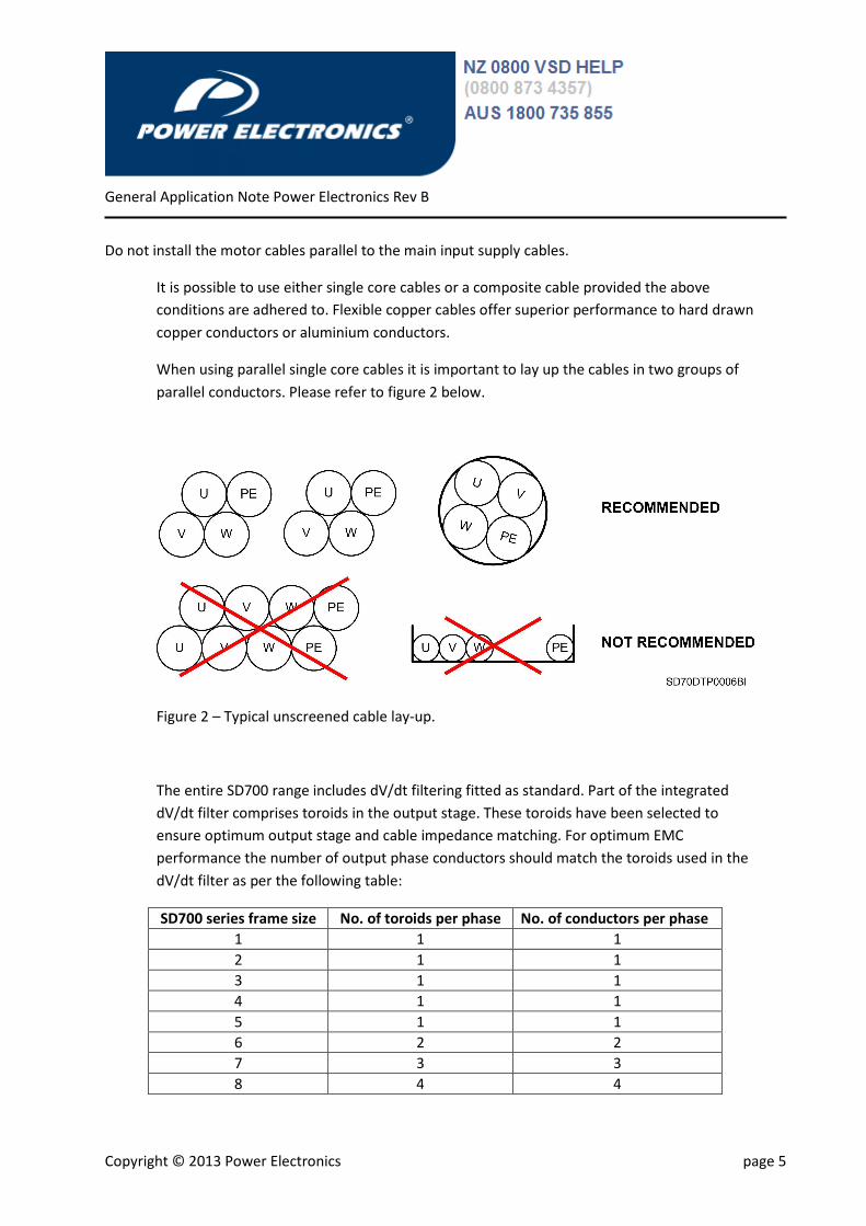
When using parallel single core cables it is important to lay up the cables in two groups of
parallel conductors. Please refer to figure 2 below.
Figure 2 – Typical unscreened cable lay-up.
The entire SD700 range includes dV/dt filtering fitted as standard. Part of the integrated
dV/dt filter comprises toroids in the output stage. These toroids have been selected to
ensure optimum output stage and cable impedance matching. For optimum EMC
performance the number of output phase conductors should match the toroids used in the
dV/dt filter as per the following table:
SD700 series frame size No. of toroids per phase No. of conductors per phase
1 1 1
2 1 1
3 1 1
4 1 1
5 1 1
6 2 2
7 3 3
8 4 4
General Application Note Power Electronics Rev B
Copyright © 2013 Power Electronics page 6
Table 2 – Number of output conductors per phase
General Application Note Power Electronics Rev B
Copyright © 2013 Power Electronics page 7
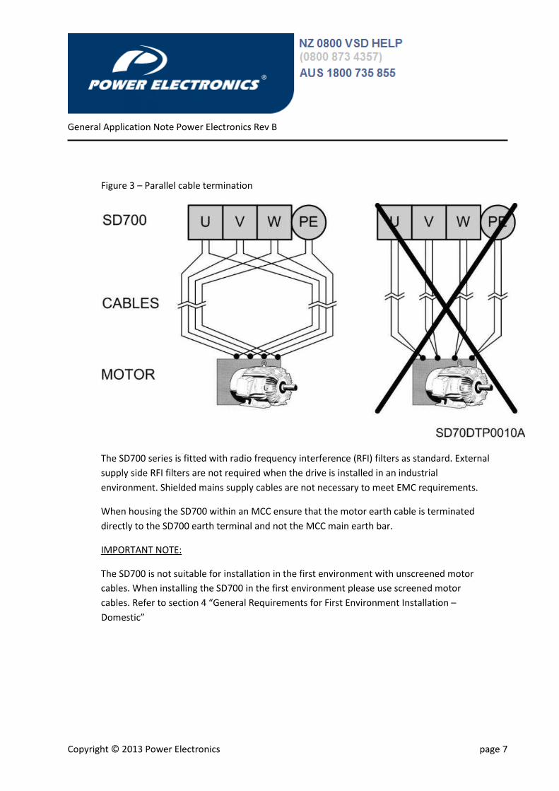
Figure 3 – Parallel cable termination
The SD700 series is fitted with radio frequency interference (RFI) filters as standard. External
supply side RFI filters are not required when the drive is installed in an industrial
environment. Shielded mains supply cables are not necessary to meet EMC requirements.
When housing the SD700 within an MCC ensure that the motor earth cable is terminated
directly to the SD700 earth terminal and not the MCC main earth bar.
IMPORTANT NOTE:
The SD700 is not suitable for installation in the first environment with unscreened motor
cables. When installing the SD700 in the first environment please use screened motor
cables. Refer to section 4 “General Requirements for First Environment Installation –
Domestic”
General Application Note Power Electronics Rev B
Copyright © 2013 Power Electronics page 8
4. SD700 Series Power Wiring – screened cables
General Requirements for Domestic and Industrial Environments
Motor cables must be three core, symmetrical with an overall screen providing greater than
90% coverage. A proper VSD screened cable with three symmetrical earths is preferable.
Conduits or metal ducting can be used for part of the shielding length provided that this is
continuous. Maximum motor cable length is not to exceed 150m.
Figure 4 – Flexible rubber braided EMC VSD cable
A screened cable gland suitably designed and sized for the screened cable type used should
be fitted at the motor end. Do not wind the screen into a “pigtail” and terminate under the
earth terminal within the motor terminal box. Terminate the earth conductor(s) to the
motor earth terminal(s) located inside the motor terminal box.
When installing the SD700 directly on the wall (no additional enclosure) a screened cable
gland suitably designed and sized for the screened cable type used should be fitted at the
SD700 gland plate. Do not wind the screen into a “pigtail” and terminate under the earth
terminal within the SD700 terminal box. Terminate the earth conductor(s) to theSD700 earth
terminal(s) located inside the terminal box.
General Application Note Power Electronics Rev B
Copyright © 2013 Power Electronics page 9
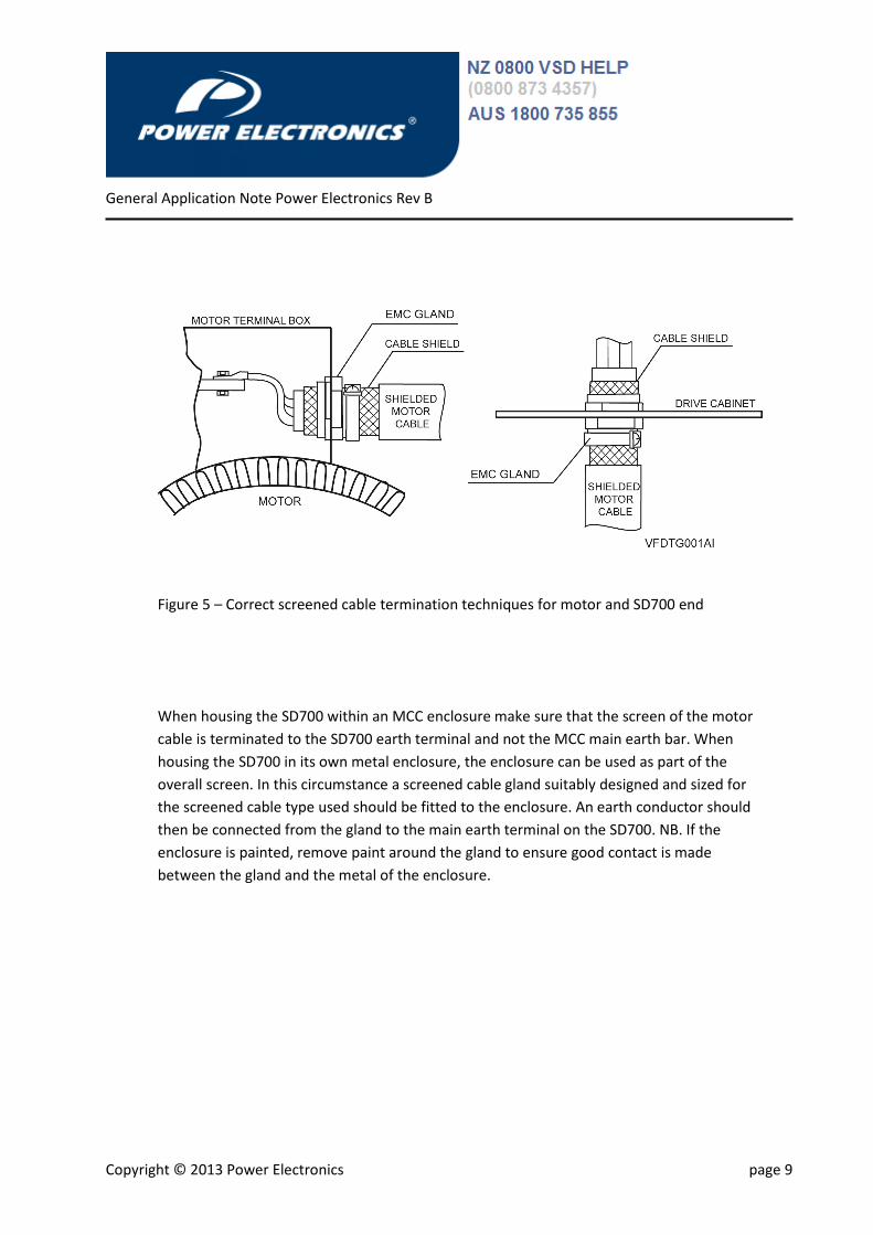
Figure 5 – Correct screened cable termination techniques for motor and SD700 end
When housing the SD700 within an MCC enclosure make sure that the screen of the motor
cable is terminated to the SD700 earth terminal and not the MCC main earth bar. When
housing the SD700 in its own metal enclosure, the enclosure can be used as part of the
overall screen. In this circumstance a screened cable gland suitably designed and sized for
the screened cable type used should be fitted to the enclosure. An earth conductor should
then be connected from the gland to the main earth terminal on the SD700. NB. If the
enclosure is painted, remove paint around the gland to ensure good contact is made
between the gland and the metal of the enclosure.
General Application Note Power Electronics Rev B
Copyright © 2013 Power Electronics page 10
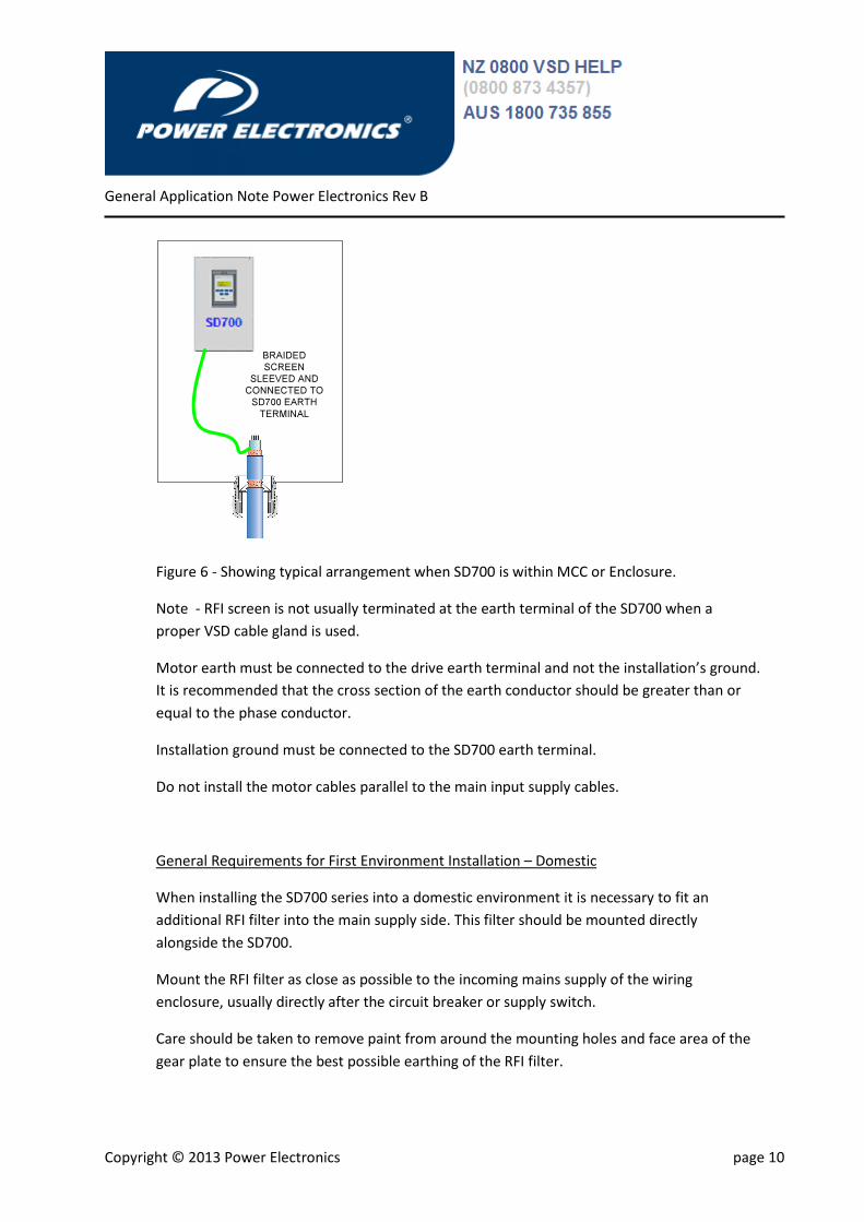
BRAIDED
SCREEN
SLEEVED AND
CONNECTED TO
SD700 EARTH
TERMINAL
Figure 6 - Showing typical arrangement when SD700 is within MCC or Enclosure.
Note - RFI screen is not usually terminated at the earth terminal of the SD700 when a
proper VSD cable gland is used.
Motor earth must be connected to the drive earth terminal and not the installation’s ground.
It is recommended that the cross section of the earth conductor should be greater than or
equal to the phase conductor.
Installation ground must be connected to the SD700 earth terminal.
Do not install the motor cables parallel to the main input supply cables.
General Requirements for First Environment Installation – Domestic
When installing the SD700 series into a domestic environment it is necessary to fit an
additional RFI filter into the main supply side. This filter should be mounted directly
alongside the SD700.
Mount the RFI filter as close as possible to the incoming mains supply of the wiring
enclosure, usually directly after the circuit breaker or supply switch.
Care should be taken to remove paint from around the mounting holes and face area of the
gear plate to ensure the best possible earthing of the RFI filter.
General Application Note Power Electronics Rev B
Copyright © 2013 Power Electronics page 11
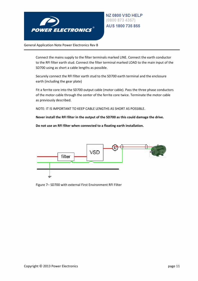
Connect the mains supply to the filter terminals marked LINE. Connect the earth conductor
to the RFI filter earth stud. Connect the filter terminal marked LOAD to the main input of the
SD700 using as short a cable lengths as possible.
Securely connect the RFI filter earth stud to the SD700 earth terminal and the enclosure
earth (including the gear plate)
Fit a ferrite core into the SD700 output cable (motor cable). Pass the three phase conductors
of the motor cable through the center of the ferrite core twice. Terminate the motor cable
as previously described.
NOTE: IT IS IMPORTANT TO KEEP CABLE LENGTHS AS SHORT AS POSSIBLE.
Never install the RFI filter in the output of the SD700 as this could damage the drive.
Do not use an RFI filter when connected to a floating earth installation.
Figure 7– SD700 with external First Environment RFI Filter
General Application Note Power Electronics Rev B
Copyright © 2013 Power Electronics page 12
5. SD700 Control Wiring
Always use screened cables for the control wiring connected to the SD700. Screened cables
comprising of twisted pairs is best for noise rejection.
Segregate control wiring from both power supply cables and motor cables. Use separate
trunking or cable tray spaced a minimum of 1m apart for unscreened motor cable
installations and 300mm for power supply cables and screened motor cable installations.
Where control wiring must cross power cables unsure this is done at 90 degrees to prevent
inducing noise or an EMF into the control wires.
Terminate the screen of the control wiring to the ground of the SD700.
MAINS
MIN
300mm
CONTROL
MIN
300mm
MAINS
MIN
1000mm
CONTROL
MIN
300mm
Screened Motor Cables Unscreened Motor Cables
Figure 6 – Control Wiring
6. SD700 Submersible Pump Requirements
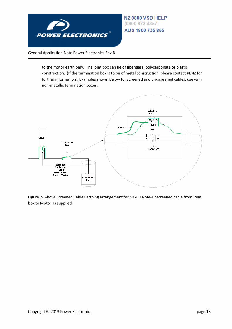
Submersible pump applications will more than likely require a joint box termination. The
connection of the earth and screened cable must be terminated as such as not to interfere
with other protective earthing (i.e.ground or external bonding).
In either case the termination joint box needs to have the motor protective earth and screen
terminated to an insulated earth stud. This is to ensure the SD700 drive earth is connected
General Application Note Power Electronics Rev B
Copyright © 2013 Power Electronics page 13
to the motor earth only. The joint box can be of fiberglass, polycarbonate or plastic
construction. (If the termination box is to be of metal construction, please contact PENZ for
further information). Examples shown below for screened and un-screened cables, use with
non-metallic termination boxes.
Figure 7- Above Screened Cable Earthing arrangement for SD700 Note-Unscreened cable from Joint
box to Motor as supplied.
General Application Note Power Electronics Rev B
Copyright © 2013 Power Electronics page 14
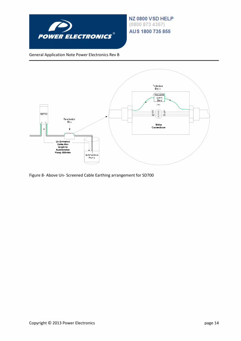
Figure 8- Above Un- Screened Cable Earthing arrangement for SD700