EMERGENCY PREPAREDNESS PLAN KEMESS TAILINGS DAM KEPP-TSF-001 DOCUMENT USERS : KEMESS & AURICO CORPORATE PERSONNEL PERSON RESPONSIBLE FOR KEEPING DOCUMENT CURRENT : KEMESS PROJECT MANAGER Revision Prepared Reviewed Approved Date Description 0 D. Bilsborow Harold Bent D. Bilsborow Nov. 2014 Final Related Documents: • AMEC Document - TSF Closure OMS Manual_REV.5_Final_22Mar2013 • Kemess South Mine Tailings Storage Facility, Dam Breach and Inundation Study - Jan 2013 • ADM-STD-004 - AuRico Emergency Crisis Management Standard • Kemess Mine – Environmental Emergency Plan June 2014 • Canadian Dam Association – Dam Safety Guidelines 2007 (2013 edition)
Revision Prepared Reviewed Approved Date Description
0 D. Bilsborow Harold Bent D. Bilsborow Nov. 2014 Final
Related Documents:
• AMEC Document - TSF Closure OMS Manual_REV.5_Final_22Mar2013 • Kemess South Mine Tailings Storage Facility, Dam Breach and Inundation Study - Jan
2013 • ADM-STD-004 - AuRico Emergency Crisis Management Standard • Kemess Mine – Environmental Emergency Plan June 2014 • Canadian Dam Association – Dam Safety Guidelines 2007 (2013 edition)
Nov. 2014 Emergency Preparedness Plan KEPP-TSF-001 Revision 0 Page 2 of 30
APPENDIX A – CRISIS FACT GATHERING SHEET ........................... 27
APPENDIX B: PHOTOS OF KEMESS TAILINGS DAM ....................... 30
Nov. 2014 Emergency Preparedness Plan KEPP-TSF-001 Revision 0 Page 3 of 30
INTRODUCTION The flowchart below displays the components, relationship and hierarchy of the AuRico Emergency & Crisis Management System. The box highlighted in RED indicates the section / component of the AuRico Emergency Management System in which you are working.
Emergency & Crisis
Management Standard
Corporate
Corporate Duty Card System
Communications Plan
Site
Emergency Management
Plan
Emergency Response
Procedures
Response Checklists
Kemess Tailings Dam
Nov. 2014 Emergency Preparedness Plan KEPP-TSF-001 Revision 0 Page 4 of 30
1.1 Aim The aim of this document is to ensure a safe and successful response to an emergency of the Tailings Storage Facility (TSF) and associated infrastructure is undertaken at the Kemess operations.
1.2 Objectives The objectives of this management plan are to;
• Identify and mitigate threats to the safety of our employees, contractors and visitors; • protect the environment and local communities; • ensure a prompt communications process is undertaken with key stakeholders; • prevent re-occurrence of the incident; • ensure we conduct our activities as a responsible corporate citizen; • restore the business back to normal operations effectively and efficiently; and • minimize reputation damage.
1.3 Scope This Emergency Preparedness Plan (EPP) describes how Emergency and Crisis Management will be undertaken at the Kemess site, specific to the Tailings Storage Facility and associated infrastructure. This EPP and the AuRico Emergency and Crisis Management Standard (ADM-STD-004) have been developed with consideration to the Canadian Dam Safety Guidelines, 2007, and Element 12, Emergency Response & Preparedness, of the AuRico Sustainability Management System (SMS). Each AuRico site must review Element 12 of the SMS along with the appropriate legislation to ensure the site meets the internal and external expectations and requirements.
1.4 Audience This EPP has been developed for those persons who are located at the Kemess site, the AuRico Corporate Response Team and other AuRico personnel who will be responsible for managing an on-site emergency. This and other related documents must be made available to the related response agencies and other relevant stakeholders. It is the responsibility of the site to ensure that all contractors and visitors undergo an induction and/or training in the site emergency management system. Full-time site personnel, should also be made aware of the AuRico Gold Emergency and Crisis Management System (ADM-STD-004).
1.5 Overview The British Columbia Controller of Water Rights requires that an Emergency Preparedness Plan (EPP) be developed for all major dams in the Province. This plan is developed to enable AuRico personnel, Provincial Emergency Program Officials, the RCMP, and other regional officials to respond to an emergency situation that might arise at the Kemess TSF. This emergency plan facilitates the mobilization of manpower and equipment and allows emergency officials to establish warning and evacuation procedures. The potential consequences of emergency situations and plausible natural disasters are included. Contingency procedures to mitigate the effects of possible loss of tailings material or impoundment water from the containment facilities are also discussed based on the conclusions of the Dam Breach and Inundation Study
Nov. 2014 Emergency Preparedness Plan KEPP-TSF-001 Revision 0 Page 5 of 30
(AMEC 2013 b). The approximate inundation limits resulting from the dam breach analysis are depicted on MAP01 of the TSF Closure OMS Manual_REV.5_Final_22Mar2013. Due to the remote location of the Kemess Mine, there is no increased potential for loss of life to the public in the event of failure of any component of the TSF. The primary intent of the plan is, therefore, to minimize potential environmental impacts associated with the failure of any component of the TSF and to minimize remediation costs. The EPP must be reviewed and updated as the TSF progresses through the formal closure phases from active to passive care to ensure that changes in both on-site personnel and regulatory agencies are captured appropriately in the plan; refer to Section 6.3 of the TSF Closure OMS Manual_REV.5_Final_22Mar2013, for the recommended review frequencies of the EPP.
1.6 Site Location and Access The Kemess Mine is located in the Toodoggone Region in north-central British Columbia, approximately 300 km northwest of Mackenzie. The primary mine site access route is the Omineca Resource Access Road (ORAR), which is an all-weather gravel road originating in Mackenzie. Mackenzie is located approximately 170 km north of Prince George, BC along Highway 97. The mine site is also accessible directly by air via helicopter (from Smithers or Prince George) or fixed wing aircraft to the existing Kemess Mine airstrip which is maintained by Kemess. However, once the airstrip is no longer required it will be decommissioned and reclaimed. Alternatively, there is also an airstrip situated at the Sturdee Valley, approximately 40 km north of the mine site. The gravel road and Sturdee airstrip must be inspected and appropriate repairs carried out prior to use. The mine location and access roads are shown on Figure.1.
Figure.1 Location of Kemess Mine
Nov. 2014 Emergency Preparedness Plan KEPP-TSF-001 Revision 0 Page 6 of 30
1.7 Key Responsibilities A summary of the key management responsibilities for emergency and crisis management are described as follows: Corporate Office: The President & Chief Executive Officer (CEO) is responsible for determining the most appropriate corporate response to an on-site emergency. This may include but is not limited to;
• initiating the Corporate Emergency Response Team (CERT); • determining whether corporate can supply or source additional resources to assist the site. • determining whether or not the Board of Directors is required to be notified; • working with the VP, Investor Relations (IR) on a response to be distributed to the relevant
media outlets; • determining the materiality of the incident and whether or not to notify capital markets; • determining the manner in which a press release is to be delivered to the various media
outlets; and • liaising with the VP, IR to determine whether or not to engage a Public Relations firm;
The Chief Operating Officer (COO) is responsible for:
• in consultation with the site manager, confirming the level of the emergency and the appropriate response.
• communicating the incident at the most appropriate time with the CEO; • providing support and communicating regularly with the relevant site manager; • providing regular updates on the emergency situation to the CEO; • assisting the CEO and VP, IR to draft an appropriate media release; • advising on corporate responsibilities; and • advising on any internal company policies.
The Vice President, IR is responsible for:
• drafting internal and external responses (as required) regarding the incident for the CEO and, where appropriate, Disclosure Committee approval;
• distributing the company endorsed response to the appropriate audiences; • assisting the CEO to determine the materiality of the incident and whether or not to notify
capital markets by way of a press release; • establishing appropriate communication sessions for the CEO to address the media; and, • engaging a PR firm as required.
Mine Sites: The site General Manager or Project Manager is responsible for:
• ensuring adequate resources (i.e. coordination, equipment, manpower, training etc.) are provided to effectively implement the Emergency Preparedness Plan;
• ensuring they notify the COO of the site emergency as soon as is practical; • ensuring outside resources such as the external Engineer are consulted; • ensure First Nation, local communities are notified in a timely manner;
Nov. 2014 Emergency Preparedness Plan KEPP-TSF-001 Revision 0 Page 7 of 30
• providing regular updates regarding the status of the emergency to the COO; • ensuring that any media communication is completed only at the express approval of the
CEO has been granted; • ensuring that the relevant regulator(s) has been notified in accordance with legislative
requirements and that this information is relayed to the COO. • ensuring to the best of their ability, the incident scene is preserved to ensure that future
investigations / reviews are able to be conducted by AuRico personnel or external agencies (Place of incident not to be disturbed);
• ensuring all incidents are reported using the AuRico Incident Reporting and Investigation Standards - ADM-STD-001 Incident Notification and Investigation Standard, and,
• ensuring the site is returned to a stable state as soon as is practical after the incident.
Each site is responsible for: • developing an Emergency & Crisis Management Plan; • ensuring it is consistent with AuRico Emergency Crisis Management Standard, ADM-STD-
004 and with Element 12 of the AuRico Sustainability Management System (SMS); • ensuring it is in line with relevant Regulations; • establishing an incident control center at the site which has continual phone contact;* • ensuring compliance to relevant legislation and license conditions regarding emergency
management; • ensuring that Emergency Response Plans and Procedures are periodically tested (minimum
1 test per shift per year) and reviewed; • maintaining emergency equipment and facilities; and, • training site personnel in effective emergency response. • Ensuring all incidents are reported using the AuRico Incident Reporting and Investigation
Standards - ADM-STD-001 Incident Notification and Investigation Standard. *Note: if the decision is made for the site incident controller to move from the established site control point, then the site incident controller is to ensure the Satellite phone is taken with the incident controller and the contact number has been established. AURICO - CRISIS MANAGEMENT STANDARD OVERVIEW Figure 2 on the following page depicts a graphical overview of the components and requirements of the AuRico crisis management and recovery / emergency management system.
Nov. 2014 Emergency Preparedness Plan KEPP-TSF-001 Revision 0 Page 8 of 30
AuRico Emergency and Crisis Management System & Structure
Site Emergency Management Plan
Emergency Response Duties
Underground Processing
Surface Mining CM&R Team
Emergency Response Team
Includes Protocols & Procedures
Emergency Procedures Manual
Includes Procedures/ Guidelines & Roles/
Responsibilities
Training & Emergency Drills De-Brief & Review • Actual Incidents • Training & Drills
Annual System Review • System & Procedures • Documentation
System Audits (2 yearly)
Corrective Action Management
• Action Register
Primary or Immediate Response (eg First-aid, Emergency Response Team Incident control by Area Management etc.)
Secondary Response to minimize impact on site
Continuous Improvement via feed-back & action management
Emergency &
Crisis Management System
Dependent on incident classification, the site GM is to determine whether or not the COO is to be
notified.
COO to notify the CEO
CERT team to be activated on CEO’s
Notification
Corporate Response / Duty Card Activation
Emergency response by Emergency Response Team
Minimization of impact on Company by Site
Management
If activated by Site General Manager
Emergency Contacts Directory
Telephone numbers
Nov. 2014 Emergency Preparedness Plan KEPP-TSF-001 Revision 0 Page 9 of 30
EMERGENCY LEVELS & DEFINITIONS
1.8 Assessment matrix for classifying incidents The manner in which AuRico responds to an emergency will be determined by the alert or risk level. The alert or risk level is to be decided by using the tables below.
Table 2. Likelihood of incident escalating
Rank Descriptor Description 1
Unlikely
• The incident is contained or controlled and it is unlikely that the incident will escalate.
• There is no chance of additional hazards. Ongoing monitoring is required
2
Moderate
• Control of the incident may have deteriorated but imminent control is probable.
• It is unlikely that the incident will further escalate.
3
Likely
• Imminent and / or intermittent control of the incident is possible but uncertain.
• Internal and or external resources are required to manage the hazard and bring control in the near term.
4
Almost certain or currently occurring
• The incident is uncontrolled and it will be difficult to bring the situation under control in the near term.
• Assistance of external resources is required to contain / control the incident.
Sum the rank from both of the columns to obtain
the risk level and the incident classification
Table 3: Incident Classification Risk Sum Assessment Results Very Low 2-3 Alert Low 4-5 Level 1 Emergency Medium 6 Level 2 Emergency High 7-8 Level 3 Emergency
Table 1. Consequence of Incident Rank Category Example of consequence
1
Minor
• No Injuries • Little or low media
interest • Chemical or liquid
release contained on site
2
Moderate
• First aid treatment for worker(s)
• Local and regional media interest
• Chemical or liquid release not contained on site
• Fire • Rockfall
3
Major
• Worker(s) require hospitalization
• Regional and national media interest
• Chemical or liquid release extends beyond lease – contained
• Fire Rockfall
• Public health & safety could be jeopardized
4
Catastrophic
• Fatality • National & international
media interest • Chemical or liquid
release extends beyond lease – not contained and has potential to, or is affecting waterways or sensitive areas
• Fire Rockfall
• Public health & safety jeopardized
Rank
Rank
Risk Sum
Nov. 2014 Emergency Preparedness Plan KEPP-TSF-001 Revision 0 Page 10 of 30
1.9 Incident Response The table that follows provides the user with the appropriate communication, actions and resources response required to effectively manage and attempt to control an on-site incident. The level of response is commensurate with the level of the emergency as determined by the assessment matrix on the previous page. An overview of the four levels of an emergency is as follows:
Table 3: Incident Classification Risk Sum Assessment Results Response - General
Very Low 2-3 Alert
An incident that can be handled on site through normal operating procedures and is deemed to be very low risk to members of the public.
Low 4-5 Level 1 Emergency
There is no danger outside the property. There is no threat to the public and there is minimal environmental impact. The situation can usually be handled entirely on site. There will be immediate control of the hazard. There is little or no media interest.
Medium 6 Level 2 Emergency
There is no immediate danger outside the property. However there is potential for the emergency to extend beyond the property boundary. Outside agencies must be notified. Imminent control of the hazard is probable but there is a chance of a threat to public and / or the environment. There may be local and regional interest.
High 7-8 Level 3 Emergency
The safety of site personnel or infrastructure has been compromised, potential for public safety to be in jeopardy from a major uncontrolled hazard. There are likely significant and ongoing impacts. Immediate multi-agency government involvement is required.
Nov. 2014 Emergency Preparedness Plan KEPP-TSF-001 Revision 0 Page 11 of 30
Incident Classification
Responses
Alert
Level 1 Emergency
Level 2 Emergency
Level 3 Emergency
Communications
Internal Discretionary Notification to off-site management
Notification to off-site management
Notification to off-site management
External / Public
Courtesy, after discussions with COO
Mandatory for any business that has notification requirements in license conditions
Planned and instructive in line with site Emergency Response Plan
Planned and instructive in line with site Emergency Response Plan
Media Reactive. CEO
approval required
Reactive. CEO approval required
Proactive media management. CEO approval required. Regional interest.
Proactive media management. CEO approval required. Regional and national interest.
Government Reactive as
required by license conditions
Determine whether to notify local emergency services. Notify regulator as required by license conditions. Notify company media relations representative.
Notify local emergency services. Notify regulator as required. Notify company corporate media relations representative.
Notify local emergency services and regulator as required. Notify company corporate media relations representative.
Actions
Internal As required by
license conditions
Initial response undertaken in accordance with the specific or corporate level ER Plan
Public safety actions to be determined. Corporate management team alerted and may be appropriately engaged to support on-scene responders. Notify mutual aid partners of potential support response.
Full implementation of site and corporate Emergency management plan.
External As required by
license conditions
On site as required by license conditions.
Potential for multi-agency (site, regional, municipal, provincial) response. Mutual aid partners
Immediate multi-agency (site, regional, municipal, provincial) response. Mutual aid partners
Resources
Internal
Immediate and local. No additional personnel required
Establish what resources would be required.
Limited supplemental resources or personnel required.
Significant incremental resources required.
External None
Begin to establish resources that may be required
Possible assistance from government agencies and external support services.
Assistance from the government agencies and external support services required.
Nov. 2014 Emergency Preparedness Plan KEPP-TSF-001 Revision 0 Page 12 of 30
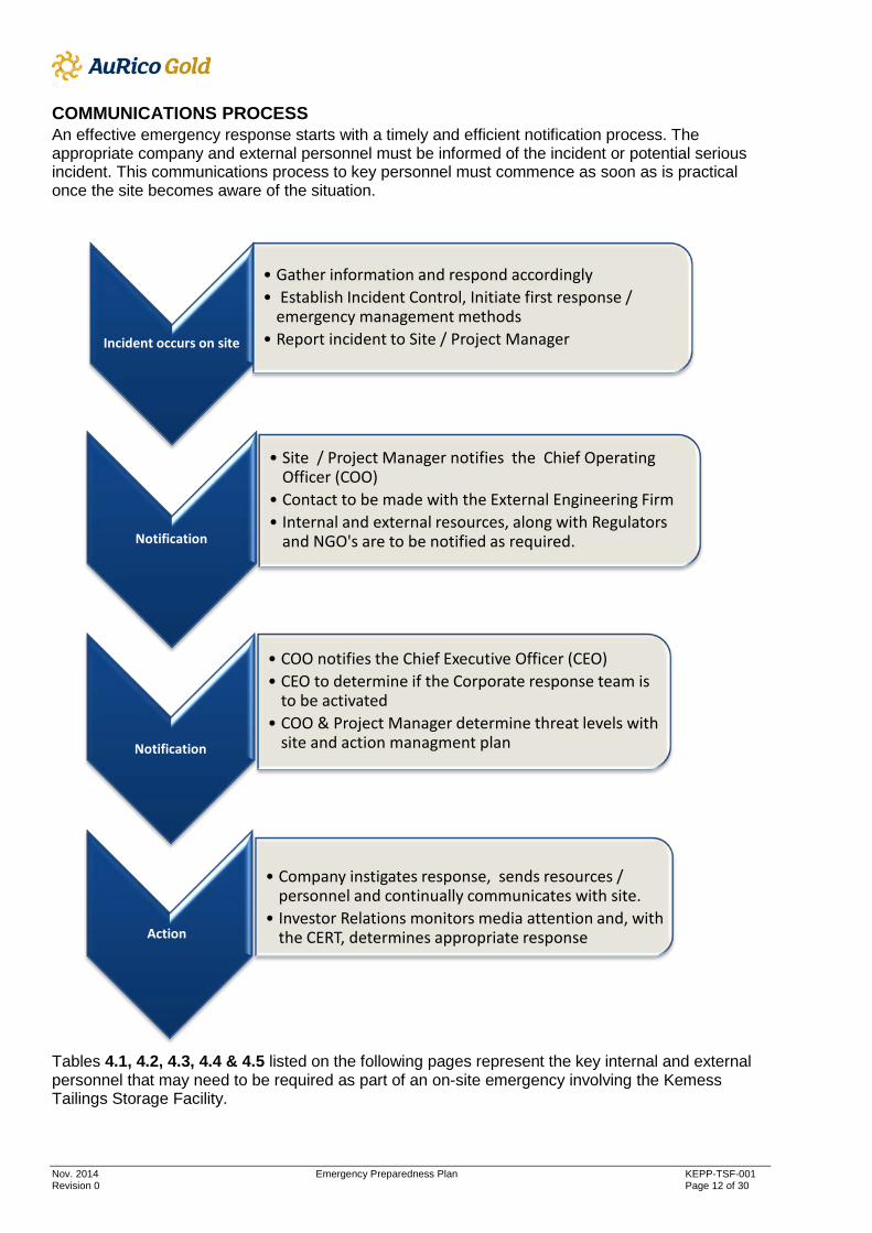
COMMUNICATIONS PROCESS An effective emergency response starts with a timely and efficient notification process. The appropriate company and external personnel must be informed of the incident or potential serious incident. This communications process to key personnel must commence as soon as is practical once the site becomes aware of the situation.
Tables 4.1, 4.2, 4.3, 4.4 & 4.5 listed on the following pages represent the key internal and external personnel that may need to be required as part of an on-site emergency involving the Kemess Tailings Storage Facility.
Incident occurs on site
• Gather information and respond accordingly • Establish Incident Control, Initiate first response /
emergency management methods • Report incident to Site / Project Manager
Notification
• Site / Project Manager notifies the Chief Operating Officer (COO)
• Contact to be made with the External Engineering Firm • Internal and external resources, along with Regulators
and NGO's are to be notified as required.
Notification
• COO notifies the Chief Executive Officer (CEO) • CEO to determine if the Corporate response team is
to be activated • COO & Project Manager determine threat levels with
site and action managment plan
Action
• Company instigates response, sends resources /
personnel and continually communicates with site. • Investor Relations monitors media attention and, with
the CERT, determines appropriate response
Nov. 2014 Emergency Preparedness Plan KEPP-TSF-001 Revision 0 Page 13 of 30
Table 4.1: AuRico Personnel Emergency Contact Information
Harold Bent Director, Environment 250-877-9411 250-877-7855 ext. 1 Gord Coyle Site Superintendent 250 699 2045 778-724-4428 Bruce Grau Site Superintendent 778-724-4425 Damien Bilsborow Director, Sustainability 647-224-2522 +1 647-260-8876
Peter MacPhail AuRico Chief Operating Officer N/A +1416-216-2773
Alternate AuRico Corporate N/A +1647-260-8880 Site Security N/A 778-724-4431 Site Satellite Phone Number. 011 8816 234 27855
Site Ambulance Satellite Phone Number.
1 600 700 1059
Note: This table is to be updated as the site transitions through the interim and formal closure periods to reflect changes in personnel and contact information.
Table 4.2: AMEC Personnel Emergency Contact Information
Personnel Title Cell Phone # Work Phone #
Andrew Witte Senior Geotechnical Engineer 604-240-5514 604-295-3264
Ed McRoberts Principal Geotechnical Engineer 778-239-4650 604-295-6127
Steve Rice Principal Engineer 604-230-5531 604-295-6190 Burnaby Office AMEC Corporate N/A 604-294-3811
The following First Nation, or Local Residents listed in table 4.3 are to be updated on the status of the emergency and the action(s) taken:
Table 4.3: Community Contact Information
First Nation, Metis or Local Resident Contact Information
Kwadacha First Nation +1 250)-471-2302
Band office number for Tsay Keh +1(250)-993-2100
Ron Steffy – local landholder +1(604)-484-8278
Nov. 2014 Emergency Preparedness Plan KEPP-TSF-001 Revision 0 Page 14 of 30
Table 4.4: External Emergency Contact Information The following Agencies listed in table 4.4 are to be updated on the status of the emergency and of the action to be taken:
Agency Contact Information
a) Emergency Management BC formally (PEP) 1+800-663-3456 (24hrs) Spill reporting line
b) MEMNG, Mines Inspector (Alan Day) 1+250-565-6131
Or 1+250-565-4327 (back up)
c) Ministry of Environment – Environmental Emergency Response Officer
1+250-565-6456 or Cell 250-612-1189
d) Dam Safety Section, Water Stewardship Division, MOE 1+250-387-3263
e) Ministry of Environment – Environmental Protection Officer 1+250-565-4168
f) MEMNG, Geotechnical Engineering 1+250-387-4808
g) Federal Dept. of Fisheries and Oceans 1+613-993-0999
h) RCMP, Mackenzie, BC 1+250-997-3288
i) Ambulance Land & Air – 1800-461-9911
The following personnel listed in table 4.5 can be contacted for availability and earthmoving assistance if deemed necessary.
Table 4.5: Earthmoving Contractors
Earthmoving Contractor Contact Information Chu Cho Industries 1. Tandem gravel truck 2. 20 m3 end dump 3. (2) 20 ton Articulating rock trucks (6x6) 4. 30 ton Articulating rock truck (6x6) 5. D6H Dozer 6. D8N Dozer 7. Komatsu D41-6 way Dozer 8. (3) 330 Excavators 9. (2) 210 excavators 10. 14M Grader 11. 740A Grader 12. 644G loader 13. IT18 loader 14. 10000kg Tridem drive boom truck
Dan Wiebe – W: 250-997-3838 C: 250-613-6566
Nov. 2014 Emergency Preparedness Plan KEPP-TSF-001 Revision 0 Page 15 of 30
Crying Stone – 1. 324E excavator. Cat 2. S210 excavator. Volvo 3. D7 cat dozer. 4. Service truck. 5. 966 wheel loader. 6. 320 excavator. 7. 2 tandom end dumps.
John French – W: 250-640-2038 Prince George.
Flintstones Mining Equipment Remaining Onsite: PC300 Excavator (Komatsu) PC710 Excavator (Komatsu) 2 HM400 Articulated Rock Trucks (Komatsu) D65 Dozer (Komatsu) D355 Dozer (Komatsu) 966 Wheel Loader (Cat) 780Grader (Champion Additional equipment available from Prince George or Burns Lake
Randy Hamp 334 Hill Road, Burns Lake, BC V0J 1E0. Phone: 1-250-692-7209.
The following AuRico earthmoving equipment listed in table 4.6 is available for use on site.
Earthmoving Equipment Make / Model Location
Loader CAT 924 Warehouse
Backhoe CAT 416 Hot Line
Excavator x 2 Hitachi 450 Various
Dozer Komatsu D-155 Hot Line
Skid Steer x 2 Bobcat Airstrip / Camp
Manlift JLG Workshop
Crane Tadano 60T Outside Workshop
Diesel Water Pump Goodwin 6” Blower room
Along with the above, the site has, among other items, snowmobiles, quad bike, compressor, fire truck, ambulance and light vehicles available for use. The contractors on the following table; 4.7 have the ability to provide remedial grouting services if required:
Nov. 2014 Emergency Preparedness Plan KEPP-TSF-001 Revision 0 Page 16 of 30
Contractor Contact details
Advanced Construction Technology Pete Bowman: Ph: 1-877-373-7248 www.advancedconstructiontechniques.com [email protected]
EMERGENCY SITUATIONS The possible emergency situations and corresponding responses for the TSF, including the Communication Directory, are listed in table 5.1 below.
Table 5.1: Emergency Situation and Associated Response
EMERGENCY Incident Classification
Dam Breach - Large and rapidly increasing uncontrolled release of water due to failure of the dam.
Level 3 Emergency - Full response required
Unusual Conditions that could lead to Dam Breach - Any condition that could result in dam failure and uncontrolled release of water from the reservoir.
Level 2 or 3 Emergency – Response dependent on circumstances
Earthquake - An earthquake alert exists or if an earthquake is felt at the Mine Site
a. Severe Damage b. Significant Damage c. Minor Damage d. No Damage
Immediate direct dam inspection required. Response level to be determined by inspection findings.
Floods - a. Slumping of dam slopes. b. Significant seepage or springs.
Level 2 or 3 Emergency – Response dependent on circumstances
Criminal Actions - Destruction or threat of Embankment or associated structures. Response dependent on circumstances
Nov. 2014 Emergency Preparedness Plan KEPP-TSF-001 Revision 0 Page 17 of 30
RESPONSE PROCEDURES – TSF
Due to the remote location of the Tailings Storage Facility, the response procedures and all necessary remedial action shall be the responsibility of the on-site personnel or their designated replacement. When required, the relevant Government Ministries and Officials shall be notified as soon as practically possible. POSSIBLE ACTIONS The necessary action to be taken in an emergency will depend on the type and scale of the emergency. Typically three levels of response are defined, each level requires an increasing level of urgency: 1. Hazardous condition or incident: The hazard or incident does not pose an immediate
danger but could develop into one. 2. Potential dam emergency: Downstream communities or agencies may need to take steps to
mitigate damage or prepare for evacuation. 3. Imminent or actual dam emergency: Widespread evacuation of the downstream population
is required. The on-site response may include, but not be limited to the following: Evacuation Require immediate evacuation of areas downstream of the Tailings Storage Facility in the event of Dam Breach. This will also require posting of guard(s) to restrict access to the TSF area to authorized rescue personnel only. As outlined in the dam breach study (AMEC 2013b), the incremental effects on flows and water surface elevations (in the extremely remote probability of a dam failure) in Kemess Creek between the TSF and Thutade Lake are predicted to be significant. Depending on the failure mode, “Overtopping” or “Piping”, the peak wave travel time from the TSF to Thutade Lake is approximately 30 to 60 minutes. Refer to the floodplain mapping shown in “MAP01” of the “TSF Closure OMS Manual_REV.5_Final_22Mar2013”, for evacuation limits and high water level predictions along the Kemess Creek and downstream watersheds. Emergency Works: Equipment and Materials Require the immediate mobilization of all necessary equipment to the Mine Site to repair any damage, repair dam slopes or slumping areas, etc. Such equipment may include any available earthmoving equipment during the interim closure period and/or local offsite equipment during the formal closure period. Works of this nature must first be discussed, and the risks assessed amongst all parties involved in order to ensure that personnel are not being put at risk and that the proposed works will in fact be sufficient to alleviate the situation. In the event of sinkhole development within the south abutment upstream beach that could threaten the integrity of the facility, the grouting contingency measures outlined in the report titled “South
Nov. 2014 Emergency Preparedness Plan KEPP-TSF-001 Revision 0 Page 18 of 30
Abutment Remedial Grouting Program Design Report” (AMEC 2013d) dated February 2013 should be implemented. Materials are available at the TSF and at the Mine post closure for use in repairing any damaged areas over the long term. Stockpiles of riprap, sands and gravels, and general rockfill have been prepared for planned maintenance or for emergency use (Refer to Volume TSF.RCP, AMEC 201b). Reservoir Lowering Require the immediate lowering of the reservoir by opening the control structure gate valve and mobilizing and commissioning pump(s) as required. In no case shall the reservoir be lowered by excavating through the earth fill. Inspection Require a site inspection within 24 hours in the event of significant deterioration of embankment fill, or structures, etc. which may affect the integrity of the system. Monitoring Require that continuous monitoring of the situation be established and maintained until the event has passed or conditions improve and the stability of the structure is no longer in question. POTENTIAL EMERGENCIES The potential emergency situations and plausible natural disasters are reviewed in this section. Contingency procedures to mitigate the effects of possible loss of tailings material or pond water from the containment facilities are also described. In all cases the site determines an initial incident classification level, which will be reviewed with senior AuRico personnel and external expert resources. The appropriate response will then be determined. The following events or situations are considered:
• Movements and/or pressures within the embankment beyond design tolerances; • Freeboard control; • Extreme runoff; • Earthquake; • Extreme low temperature; • Failure or loss of critical instrumentation; • Avalanche or debris slide; and • Forest fire.
Note: Under all emergency circumstances, the Site, AuRico Management and any relevant external agencies are to consult the Kemess South Mines – Tailings Storage Facility Dam Breach and Inundation Study – January 2013.
Nov. 2014 Emergency Preparedness Plan KEPP-TSF-001 Revision 0 Page 19 of 30
1.10 Movements and/or Pressures Design Tolerances
GENERAL
The three specific operating conditions for the TSF embankment based on monitored instrumentation performance are listed below. Note that only one of the unacceptable pore pressures or movements is required for the contingency plans to be implemented. Response measures are to be consistent with the requirements of the Assessment matrix for incident classification.
Table 6.1: Specific Operating Conditions and Required Actions
Piezometer Inclinometer Action
Incident Classification
Levels
Pore pressures are less than those assumed for design.
Movement rates are acceptably low and in line with previous movement rates noted in the dam foundation.
Nominal conditions, no actions required.
Pore pressures approaching design levels, and/or showing trend of rapid increase that, if continued, may reach or exceed design levels.
Movement rates significantly higher than previously experienced in dam foundation.
Inform TSF Geotechnical Consultant and appropriate regulatory agencies immediately. Carry out more frequent monitoring of selected piezometers/inclinometers as directed by consultant.
Level 2 Response Required
Pore pressures, in multiple piezometers, typically exceed pressures assumed in design, to the point that factor of safety would be well below acceptable level.
Relatively rapid movement rates.
Inform TSF Geotechnical Consultant and appropriate regulatory agencies immediately. Consultant to assess situation and the need for additional remedial construction measures.
Level 3 Response Required
Nov. 2014 Emergency Preparedness Plan KEPP-TSF-001 Revision 0 Page 20 of 30
THRESHOLD LEVELS
Threshold levels for piezometers in the glaciolacustrine foundation unit, and in fractured bedrock (which can potentially transmit high pore pressures into the glaciolacustrine unit) have been established by the Design Engineer based on the pore pressure assumptions in the stability analyses. Threshold movement levels for inclinometers apply to movements within the glaciolacustrine unit, in terms of downstream movement rates. Downstream movement rates for each inclinometer reading can be calculated as follows:
Determine the incremental downstream displacement, in the glaciolacustrine unit (from its bottom to its top), since the previous reading. The A-axis displacement represents the downstream displacement. Divide the incremental movement in the glaciolacustrine unit by the number of days between the previous and current reading sets to determine the movement rate.
Threshold levels for each of the piezometer groups in south abutment and main valley as well as the inclinometers are listed in “TSF Closure OMS Manual_REV.5_Final_22Mar2013”, respectively. POTENTIAL INCIDENT REPONSE
It is important to note that judgment must be exercised in applying these actions. For example, a single piezometer could yield a yellow or even red light condition, while all others remain within the green light zone, and the inclinometers show no significant movements. This situation would obviously present much less of a concern as compared to a situation where multiple inclinometers and/or piezometers in the same general area are approaching or indicating yellow and/or red light conditions. The required initial response / actions for the “Green”, “Yellow” and “Red” light conditions are presented in Table 6.1 of this document.
1.11 Freeboard Control
GENERAL
The TSF spillway is designed to accommodate the routed IDF (seasonally adjusted) while providing sufficient freeboard for safe operation of the impoundment. An additional 3 m of freeboard is provided above the spillway control structure invert to account for wave run-up and long term settlement of the embankment. The design maximum instantaneous water level coincident with routing of the IDF is El. 1507.5 m which coincides with the maximum permitted water level for the facility as set out in the Stage 12 Crest Raising Permit Amendment. Contingency plans have been developed in the event that the water level within the impoundment has risen significantly due to some flood or storm event, or due to blockage (either partial or complete) of the spillway inlet or control structure to the point that the freeboard allowance is being infringed upon.
Nov. 2014 Emergency Preparedness Plan KEPP-TSF-001 Revision 0 Page 21 of 30
POTENTIAL INCIDENT
• Tailings pond water reaches the maximum permitted level (El. 1507.5 m). INCIDENT RESPONSE • Determine incident classification level. • Notify the site Project Manager immediately. Determine / confirm next steps, which may
include; o Notify TSF Geotechnical Consultant immediately. o Notify the BC Ministry of Energy and Mines (MEM). Send daily updates while the water
level is at or above the permitted level. o Notify the BC Ministry of Environment (MOE) and the Federal Department of Fisheries
and Oceans (DFO). o Commence further inspections of the dam crest and overall embankment. o Read dam piezometers to check if readings are out of normal range. o View digital images of the spillway inlet and control structures for signs of blockage. o Monitor the water level daily using the remote monitoring system. o Mobilize key personnel to site for visual inspection of situation. o Mobilize key equipment to site for remedial action as necessary.
POTENTIAL INCIDENT
Diminishing Freeboard – Tailings pond water: o Is projected to be at the effective crest level (El. 1509.0 m) within 10 days based on
the rate of increase over the previous 24 hours or over the previous 10 days, whichever is greater; or
o Rises to within 0.5 m of dam crest (EL. 1508.5 m). INCIDENT RESPONSE • Determine incident classification level. • Notify the site Project Manager immediately. Determine / confirm next steps, which may
include; o Notify TSF Geotechnical Consultant. o Notify Emergency contacts (police, MEM, MOE, DFO) of possible dam failure. o Maintain 24-hour visual observation of water levels (from safe location) and continuous
acquisition of monitoring data. o Read dam piezometers to check if readings are out of normal range. o Continue further inspections of the dam crest and overall embankment. o Open control structure gate valve to increase flow rate and lower water level. o Evacuate the valley downstream of the dam as per “MAP01” in the “TSF Closure OMS
Manual_REV.5_Final_22Mar2013”. o Execute emergency remedial construction activities to increase freeboard and protect
the dam.
Nov. 2014 Emergency Preparedness Plan KEPP-TSF-001 Revision 0 Page 22 of 30
1.12 Extreme Runoff
During normal closure conditions, sufficient freeboard will be provided within the impoundment to route surface runoff though the closure spillway to South Kemess Creek. The network of diversion ditches and drainage swales constructed on the downstream dam shell will also intercept and convey surface runoff safely around the buttresses to Kemess Creek. The spillway and diversion ditches (collectively termed as the closure diversion system) are designed to contain and convey extreme runoffs (i.e. runoffs consequent of the IDF and 24hr duration 200yr storm events, respectively). However, the occurrence of a major storm event (i.e. the minimum storm event being the design event for the diversion ditches) will necessitate a site inspection to confirm the integrity of the entire closure diversion system, namely the diversion ditches and drainage swales, and investigate any erosive damage to the vegetated cyclone sand buttresses and the potential impact to the integrity of the TSF as a whole. Water level and flow measurements through the spillway inlet channel combined with the weather station data from Group IX will be used to monitor the magnitude of storm events with specific alarm levels defining extreme runoff events. Repairs are to be carried out as soon as reasonably possible based on the severity of the damage and potential for impact to the overall integrity of the TSF in consideration of the potential for aggravating such deficiencies during subsequent storm events.
Nov. 2014 Emergency Preparedness Plan KEPP-TSF-001 Revision 0 Page 23 of 30
1.13 Earthquake GENERAL The Kemess South property is located in an area of low seismicity. However, the occurrence of a significant earthquake could result in damage to, or failure of earthworks as well as triggering of avalanches or debris slides. The site is situated in the Northern BC earthquake source zone of which there are no known earthquakes of magnitude 5 or greater (Basham et al, 1982). The maximum observed magnitude for this zone from historic data is 4.5. However, due to the lack of historic data for this site, a conservative maximum magnitude earthquake of 6.0 has been selected for design purposes. The design earthquake is the Maximum Credible Earthquake (MCE)1 for both operations and closure. The MCE for the project is defined as a Magnitude, M=6.0 event producing a maximum peak horizontal ground acceleration, amax=0.19 g. POTENTIAL INCIDENT REPONSE
The occurrence of an earthquake would mandate an immediate site inspection to assess the integrity of the facility and whether any remedial measures are required. Smaller seismic events may also trigger a site inspection. The minimum earthquake to trigger a site inspection would be a M5.0 event within a 100 km radius of the site2 as measured by the existing seismograph network operated by the Geological Survey of Canada (GSC). The closest seismographs of interest are located at Dease Lake, Fort Nelson, Bull Mountain, Fort St. James and Prince Rupert which should provide sufficient data to interpret the magnitude and epicenter of a significant earthquake local to the Kemess Mine site. In the final closure phase, an alert account is to be established with GSC following closure of the site to alert the appropriate AuRico Corporate Representative of such events. The need to perform a site inspection for seismic events less than an M5.0 event would be evaluated with the aid of the remote monitoring systems. For the trigger levels discussed below, the scale of the seismic events are defined in terms of the Modified Mercalli Intensity (MMI) scale. The MMI scale describes the intensity of shaking and level of damage rather than the Richter Magnitude scale which represents a measure of energy released. Based on the history of the south abutment regarding sinkhole development a stockpile of 7,600 m3 gravel material (G2) has been maintained alongside of the spillway service road east of the instrumentation hut at the south abutment for immediate use in filling/plugging any sinkholes in the event that they were to develop. There are also two other processed materials stockpiles at this location with a total of 5,800 m3 of D6 and 2,200 m3 D4/D5 riprap to be used for repair work of the spillway and diversion ditches in case of emergencies. Major Earthquake Event (Modified Mercalli Intensity VI or Greater) 1 The MCE is defined as having a return period of 10,000 years. 2 Note that the epicentre of the Masset earthquake (magnitude 7.7) which occurred off the west coast of British Columbia on October 27, 2012 was approximately 500 km from the Kemess Mine site. The earthquake was not felt at site by any of the onsite personnel.
Nov. 2014 Emergency Preparedness Plan KEPP-TSF-001 Revision 0 Page 24 of 30
Recognition: An event of Modified Mercalli Intensity (MMI) of 5.0 or greater is characterized by experiencing difficulty standing, hanging objects that quiver, masonry cracks, waves on ponds, dislodging of loose material from sloping ground, and possible minor injuries. This is roughly equivalent to a Richter Magnitude 5.0 or greater event. Action:
• Initiate continuous monitoring of tailings embankment piezometers and inclinometers using the remote monitoring system and compare with previously established threshold levels.
• Notify the site Project Manager and determine / confirm next steps, which may include; • Arrange for an immediate inspection by a suitably qualified Professional Engineer familiar
with the design of the facility. • Immediate inspection of the tailings embankment for obvious deformation, movement or
seepage. • Immediate inspection of all spillways and ditches for cracking, rupture, leakage or other
damage. Minor Earthquake Event (Modified Mercalli Intensity V or less) Recognition: Felt outdoors as well as indoors (characterized by disturbance of liquid surfaces, small objects being displaced, doors swinging open or closed, and pictures moving). Action:
Initiate continuous monitoring of tailings embankment piezometers and inclinometers using the remote monitoring system and compare with previously established threshold levels. Based on the results of instrumentation monitoring it may be necessary to perform a site inspection which would include general inspection of the tailings embankment for obvious deformation, movement or seepage as well as inspection of the spillway and diversion ditch networks.
Nov. 2014 Emergency Preparedness Plan KEPP-TSF-001 Revision 0 Page 25 of 30
1.14 Extreme Low Temperature Prolonged periods of sub-zero temperatures will have minimal effect on the operation of the TSF. However the following issues are of concern:
Ice build-up in the spillway restricting or diverting flows in the inlet, control structure or spillway channel. Malfunction of instrumentation due to freezing of electronics.
Design features included to mitigate the effects of low temperatures include the following: Instrumentation groupings were designed with low temperature resistance electronics. The spillway control structure includes a notched weir to provide sufficient continual flow during winter conditions to reduce icing of the channel.
Action: • Use the remote monitoring system cameras and thermistors to identify ice build-up in the
spillway inlet. • Based on the results of instrumentation monitoring, it may be necessary to perform a site
inspection which could require mobilization of equipment to remove ice from the inlet channel.
1.15 Power Failure or Loss of Critical Instrumentation The TSF itself does not require power in order to operate post closure, however the monitoring system does require power in order to manage the array of instrumentation installed throughout the dam. Each instrument monitoring group is powered by a solar panel connected to a deep cycle rechargeable battery pack. A power failure or equipment malfunction would be evident in the inability to remotely interrogate the monitoring systems. There are several possible scenarios in which the monitoring system could experience a complete or partial power failure such as equipment malfunctions, lightning strikes or animal interference. Action:
• The loss of power or loss of several pieces of critical monitoring instrumentation could require, depending on the time of year, a separate site visit in order to investigate the cause of the failure and, if necessary, repair any faulty or damaged components.
1.16 Avalanche and Debris Slide The project area is in relatively steep topography, which is prone to avalanches. However, the storage capacity of the tailings basin is not likely to be affected by such events. Active avalanche concerns have diminished since downstream construction on the dam was completed in 2009. Avalanches into the pond would be identified by rises in the water level measured at the control structure. A portion of the R1 ditch, constructed in 2008 and 2009, has an adjacent avalanche containment berm constructed of large sized riprap to protect the dam cyclone sand material. Based on field observations since 2009, avalanches have been adequately controlled without damaging or causing erosion to the dam fill material.
Nov. 2014 Emergency Preparedness Plan KEPP-TSF-001 Revision 0 Page 26 of 30
1.17 Forest Fire Since the TSF is an earth fill structure the potential damage to the embankment itself resultant of a forest fire is quite low however the above ground monitoring system could be partially or completely destroyed due to fire. A possible scenario impacting the integrity of the TSF would be for a large forest fire to burn across the dam shell thus removing the protective vegetation cover over the cyclone sand buttresses. If the fire were to be followed (immediately or after some time) by a heavy rainfall event there is potential for significant erosion of the cyclone sand and overburden soils. Action:
• In the event of a major forest fire at the TSF a site inspection should be performed in order to assess if any remedial actions are required as well as to inspect and repair the monitoring system as necessary.
REVIEWS
AuRico shall administer review of the Emergency Preparedness Plan as follows:
• Names and phone numbers of designated officials shall be verified and updated as required. • All relevant personnel shall be given a refresher briefing on the EPP and routine inspection
procedures, particularly with respect to any changes to the EPP or the inspection procedures.
• The site is to undergo an annual test of the EPP. All tests and mock emergencies are to be recorded and filed, with any recommendations and action plans noted and monitored for implementation.
• The EPP shall be reviewed for adequacy following each dam safety review (once every 5 years); or
• As required or directed by the Ministry of Environment or other Regulatory body. REVISION HISTORY List of Versions
Revision No.
Date Section Page(s) Purpose of the modification
0 November, 2104
All All Original Version
Nov. 2014 Emergency Preparedness Plan KEPP-TSF-001 Revision 0 Page 27 of 30
APPENDIX A – CRISIS FACT GATHERING SHEET This question sheet should be completed by the site and the CERT, if activated. Name: __________________________________ Position: ___________________________________ Date: ___________________________________ DESCRIBE WHAT HAPPENED What happened? _______________________________________________________________________________ _______________________________________________________________________________ _______________________________________________________________________________ Where did the incident occur? ____________________________________________________________________________ When did the incident occur? ____________________________________________________________________________ How did the incident occur? ____________________________________________________________________________ _______________________________________________________________________________ Does the incident present an immediate danger to human health or the environment? ____________________________________________________________________________ Describe injuries, if any. ____________________________________________________________________________ Have employees’ families been notified? Yes___ No___ if yes, how: _____________________________________________________________ What is being done to assist employees’ families? ____________________________________________________________________________ _______________________________________________________________________________
Nov. 2014 Emergency Preparedness Plan KEPP-TSF-001 Revision 0 Page 28 of 30
What have the rest of the employees been notified? ____________________________________________________________________________ COMMUNITY/ENVIRONMENTAL IMPACT Has the incident impacted outside of the site or operation? _______________________________________________________________________________ If so, how and where? _______________________________________________________________________________ _______________________________________________________________________________ What is the extent of the damage? _______________________________________________________________________________ _______________________________________________________________________________ Does the community need to be evacuated? _______________________________________________________________________________ Can the incident scene be secured? Or can the spill be controlled? _______________________________________________________________________________ _______________________________________________________________________________ CURRENT STATUS Who is the senior employee in charge? ____________________________________________________________________________ What external emergency agencies have been contacted? _______________________________________________________________________________ Has there been any contact with local/provincial/federal government officials? If yes, whom? _______________________________________________________________________________ _______________________________________________________________________________ What is the determined schedule for updates from sites to be available? _____________________________________________________________________________
Nov. 2014 Emergency Preparedness Plan KEPP-TSF-001 Revision 0 Page 29 of 30
BUSINESS DISRUPTION Extent of damage to facilities? _______________________________________________________________________________ _______________________________________________________________________________ _______________________________________________________________________________ Specific facilities and locations hardest hit? _______________________________________________________________________________ Potential for further damage? _______________________________________________________________________________ Have the facilities been secured? _____________________________________________________________________________ Additional facilities at risk? _______________________________________________________________________________ Has the operation been interrupted? Describe: _______________________________________________________________________________ What can be done to return the site to normal operation? _____________________________________________________________________________ _______________________________________________________________________________ ______________________________________________________________________________ _______________________________________________________________________________
Nov. 2014 Emergency Preparedness Plan KEPP-TSF-001 Revision 0 Page 30 of 30
APPENDIX B: PHOTOS OF KEMESS TAILINGS DAM
Photo: Main Dam of TSF Viewed toward the East. Completed spillway on RHS
Photo: Tailings Seepage Recycle Pond. Tailings Sedimentation Pond on RHS.