Page 1
Emerging Energy-Efficiency and Greenhouse
Gas Mitigation Technologies for the Pulp and
Paper Industry
Lingbo Kong, Ali Hasanbeigi, Lynn Price
China Energy Group
Energy Analysis and Environmental Impacts Department
Environmental Energy Technologies Division
Lawrence Berkeley National Laboratory
December 2012
This work was supported by the China Sustainable Energy Program of the
Energy Foundation and Dow Chemical Company (through a charitable
contribution) through the U.S. Department of Energy under Contract No. DE-
AC02-05CH11231.
ERNEST ORLANDO LAWRENCE
BERKELEY NATIONAL LABORATORY
LBNL-5956E
Page 2
Disclaimer
This document was prepared as an account of work sponsored by the United States
Government. While this document is believed to contain correct information, neither the
United States Government nor any agency thereof, nor The Regents of the University of
California, nor any of their employees, makes any warranty, express or implied, or assumes
any legal responsibility for the accuracy, completeness, or usefulness of any information,
apparatus, product, or process disclosed, or represents that its use would not infringe
privately owned rights. Reference herein to any specific commercial product, process, or
service by its trade name, trademark, manufacturer, or otherwise, does not necessarily
constitute or imply its endorsement, recommendation, or favoring by the United States
Government or any agency thereof, or The Regents of the University of California. The
views and opinions of authors expressed herein do not necessarily state or reflect those of
the United States Government or any agency thereof, or The Regents of the University of
California.
Ernest Orlando Lawrence Berkeley National Laboratory is an equal opportunity employer.
Page 3
Emerging Energy-efficiency and Greenhouse Gas Mitigation Technologies for
the Pulp and Paper Industry
Lingbo Kong1, 2
, Ali Hasanbeigi1, Lynn Price
1
1 China Energy Group, Energy Analysis and Environmental Impacts Department
Environmental Energy Technologies Division
Lawrence Berkeley National Laboratory
2
State Key Laboratory of Pulp and Paper Engineering,
South China University of Technology
Abstract
The pulp and paper industry ranks fourth in terms of energy consumption among industries
worldwide. Globally, the pulp and paper industry accounted for approximately 5 percent of total
world industrial final energy consumption in 2007, and contributed 2 percent of direct carbon
dioxide (CO2) emissions from industry. Worldwide pulp and paper demand and production are
projected to increase significantly by 2050, leading to an increase in this industry’s absolute energy
use and greenhouse gas (GHG) emissions. Development of new energy-efficiency and GHG
mitigation technologies and their deployment in the market will be crucial for the pulp and paper
industry’s mid- and long-term climate change mitigation strategies. This report describes the
industry’s processes and compiles available information on the energy savings, environmental
and other benefits, costs, commercialization status, and references for 36 emerging technologies
to reduce the industry’s energy use and GHG emissions. Although studies from around the world
identify a variety of sector-specific and cross-cutting energy-efficiency technologies that have
already been commercialized for the pulp and paper industry, information is scarce and/or
scattered regarding emerging or advanced energy-efficiency and low-carbon technologies that are
not yet commercialized. The purpose of this report is to provide engineers, researchers, investors,
paper companies, policy makers, and other interested parties with easy access to a well-structured
resource of information on these technologies.
Page 5
Contents
Abstract ...........................................................................................................................................iii
1. Introduction .................................................................................................................................. 1
2. Description of Pulp and Paper Production ................................................................................... 5
2.1. Pulp and Paper Production Processes and Energy Use ......................................................... 5
2.2. GHG Impact of the Pulp and Paper Industry ...................................................................... 10
3. Emerging Energy-Efficiency and GHG Mitigation Technologies for the Pulp and Paper
Industry ........................................................................................................................................... 11
3.1. Emerging Pre-treatment Technologies ................................................................................ 11
3.1.1. Microwave Pre-treatment for Chemical Pulping .......................................................... 11
3.1.2. Biological Pre-treatment for Mechanical Pulping ........................................................ 12
3.1.3. Chemical Pre-treatment with Oxalic Acid for Mechanical Pulping ............................. 14
3.2. Emerging Pulping Technologies ......................................................................................... 17
3.2.1. Directed Green Liquor Utilization Pulping .................................................................. 17
3.2.2. Membrane Concentration of Black Liquor .................................................................. 19
3.2.3. Dual-pressure Reheat Recovery Boiler ........................................................................ 21
3.2.4. Borate Auto-causticizing .............................................................................................. 23
3.2.5. Steam Cycle Washing .................................................................................................. 25
3.2.6. Recycled Paper Fractionation ....................................................................................... 27
3.2.7. New Flotation Deinking ............................................................................................... 28
3.2.8. Surfactant Spray Deinking ........................................................................................... 34
3.2.9. Pulsed Power Technology for Decontamination of Recycled Paper ........................... 35
3.3. Emerging Papermaking Technologies ................................................................................. 37
3.3.1. Aq-vane Technology .................................................................................................... 37
3.3.2. High Consistency Papermaking ................................................................................... 38
3.3.3. Dry Sheet Forming ....................................................................................................... 40
3.3.4. Displacement Pressing ................................................................................................. 42
3.3.5. New Fibrous Fillers ...................................................................................................... 43
3.3.6. Laser Ultrasonic Stiffness Sensor ................................................................................. 45
3.4. Emerging Paper Drying Technologies ................................................................................ 47
3.4.1. Gas-fired Dryer ............................................................................................................. 47
3.4.2. Boost Dryer .................................................................................................................. 48
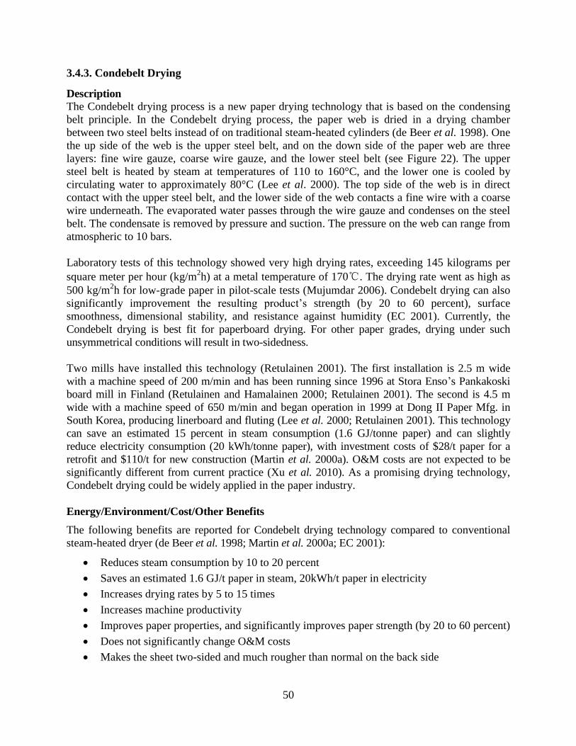
3.4.3. Condebelt Drying ......................................................................................................... 50
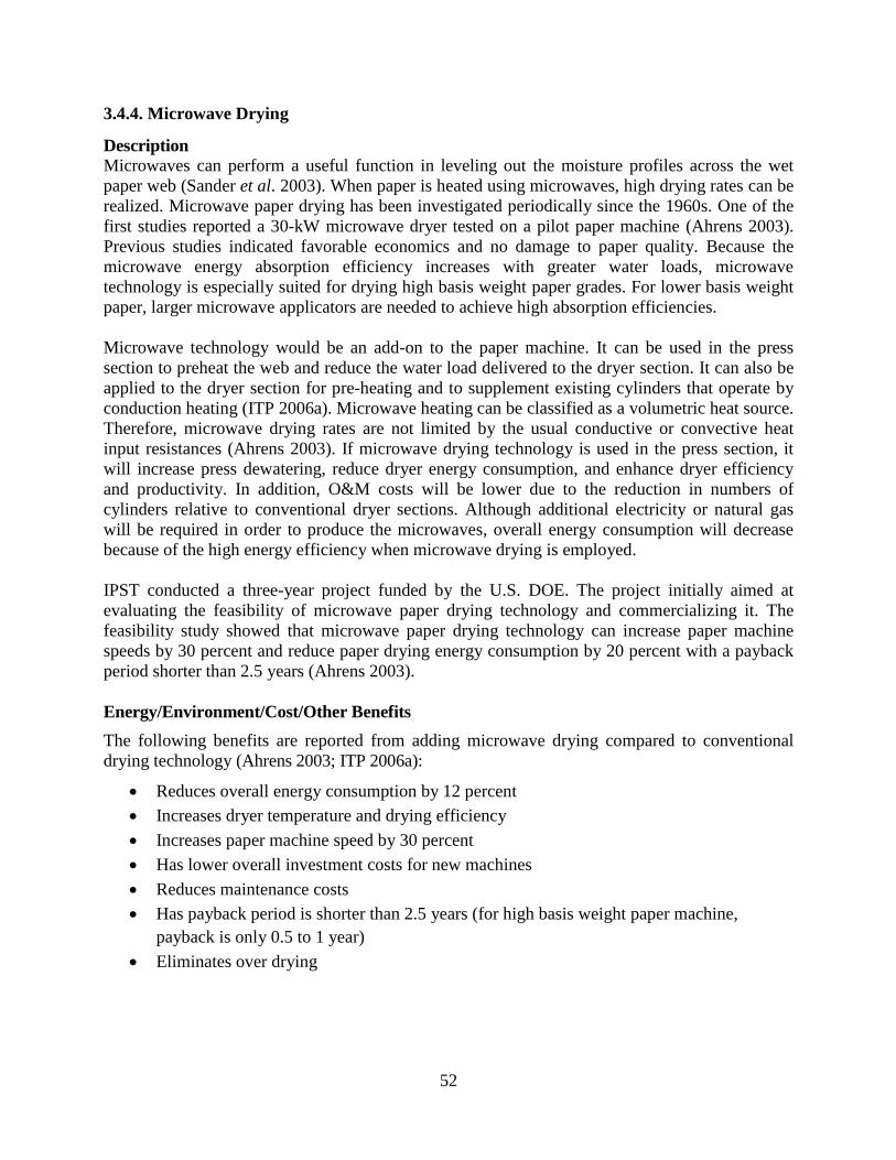
3.4.4. Microwave Drying ....................................................................................................... 52
Page 6
3.5. Emerging Byproduct/Biomass/Waste Heat Utilization Technologies ................................ 54
3.5.1. Black Liquor Gasification ............................................................................................ 54
3.5.2. Biomass Gasification .................................................................................................... 56
3.5.3. Hemicellulose Extraction before Chemical Pulping .................................................... 58
3.5.4. LignoBoost ................................................................................................................... 61
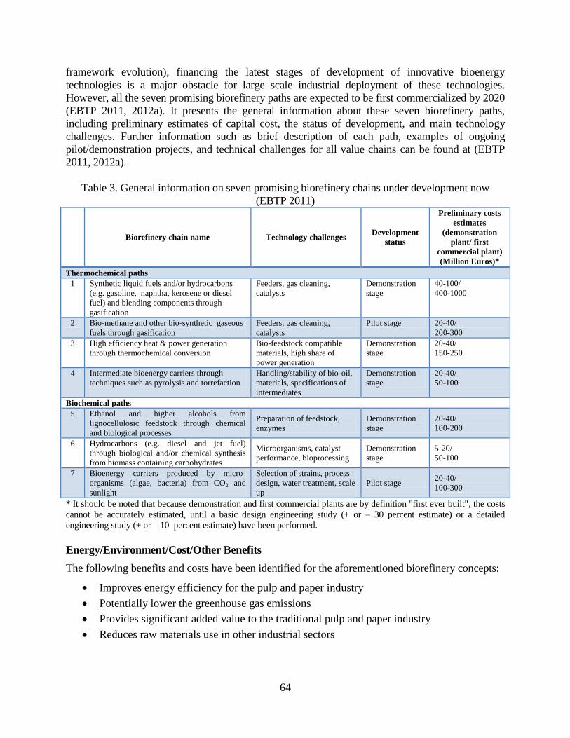
3.5.5. Other Biorefinery Concepts .......................................................................................... 62
3.5.6. Use of Residuals in Concrete Production ..................................................................... 65
3.5.7. Transport Membrane Condenser .................................................................................. 67
3.6. Emerging Carbon Capture Technologies for the Pulp and Paper Industry ......................... 69
3.6.1. BLGCC with Pre-combustion Carbon Capture ............................................................ 72
3.6.2. Biomass Conversion with Pre-combustion Carbon Capture ........................................ 74
3.6.3. Oxy-fuel Combustion Technology ............................................................................... 76
3.6.4. Post-combustion Carbon Capture Using Chemical Absorption ................................... 77
3.6.5. Bio-Technological Carbon Capture .............................................................................. 79
3.6.6. CO2 Sequestration in Recycled Mineral Fillers ........................................................... 81
3.7. Nanotechnology in Pulp and Paper Production ................................................................... 83
Summary and Conclusions ............................................................................................................. 86
Acknowledgments .......................................................................................................................... 86
References ...................................................................................................................................... 87
Page 7
List of Tables
Table 1. Emerging energy-efficiency and GHG mitigation technologies for the pulp and paper
industry ............................................................................................................................... 3
Table 2. Direct GHG emissions sources in the pulp and paper industry ........................................ 10
Table 3. General information on seven promising biorefinery chains under development now ...... 64
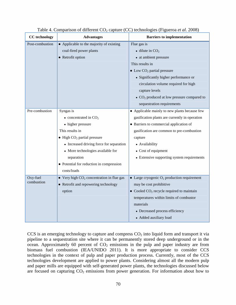
Table 4. Comparison of different CO2 capture technologies ......................................................... 70
Page 8
List of Figures
Figure 1. Annual world paper and paperboard production .............................................................. 1
Figure 2. Flow diagram of the pulping and papermaking process ................................................... 6
Figure 3. Enzymatic pre-treatment of wood chips for mechanical pulping ................................... 14
Figure 4. Chemical pre-treatment using OA in TMP mill ............................................................. 16
Figure 5. The difference between conventional kraft pulping and D-GLU pulping ..................... 18
Figure 6. Membrane technology for black liquor pre-evaporation ................................................ 20
Figure 7. Diagram of dual pressure reheat recovery boiler ........................................................... 22
Figure 8. Borate auto-causticizing process .................................................................................... 24
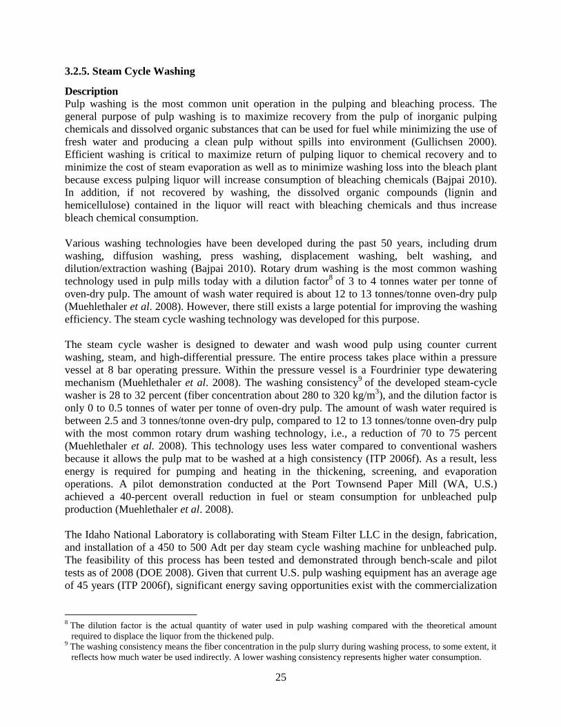
Figure 9. A steam cycle washer ..................................................................................................... 26
Figure 10. Single-loop fractional deinking .................................................................................... 28
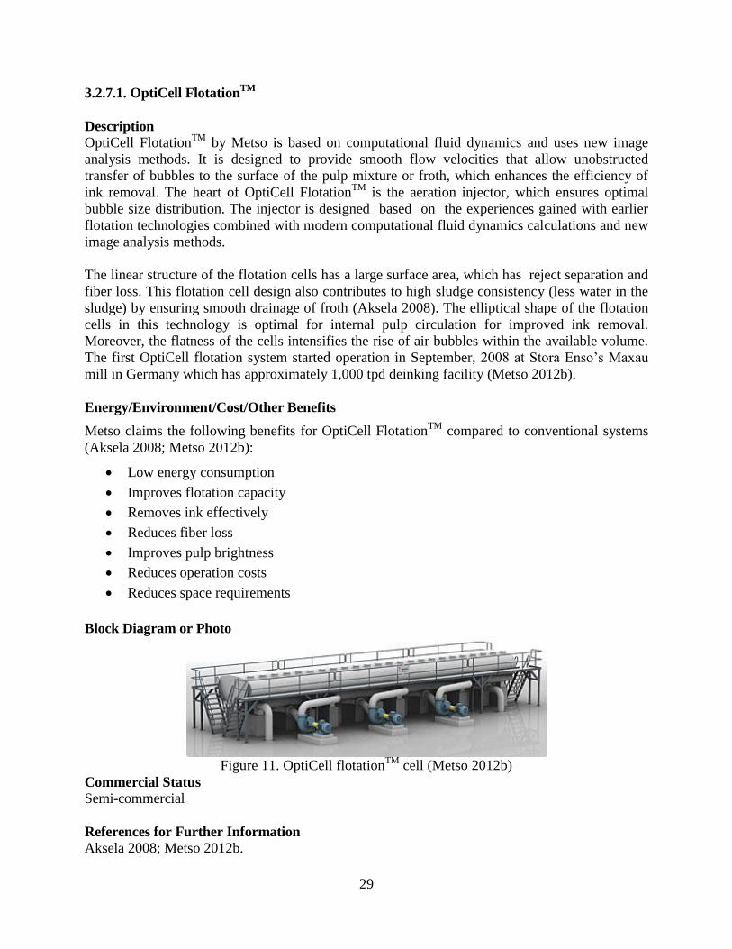
Figure 11. OptiCell flotationTM
cell ............................................................................................... 29
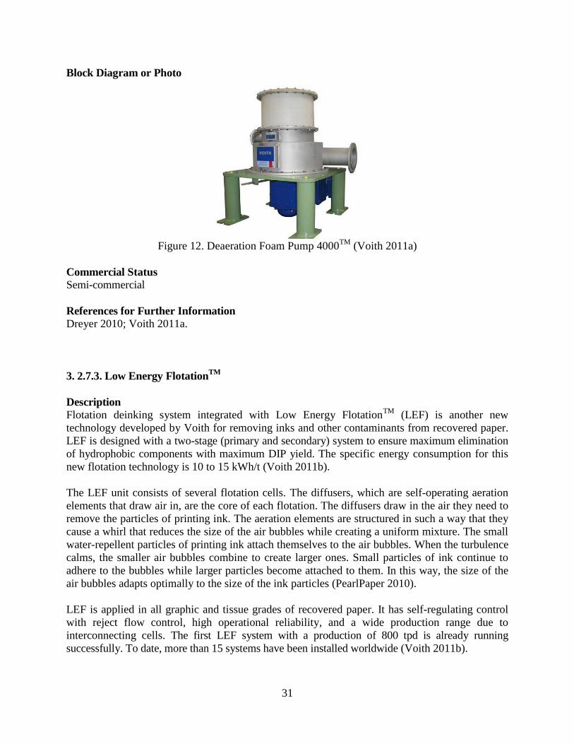
Figure 12. Deaeration Foam Pump 4000TM
................................................................................... 31
Figure 13. Low Energy Flotation Cell structure ............................................................................ 32
Figure 14. Mac flotation cell with low-pressure injectors ............................................................. 33
Figure 15. Surfactant spray deinking in a mill trial ....................................................................... 35
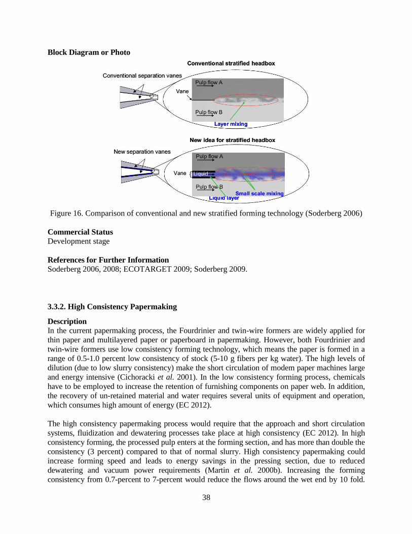
Figure 16. Comparison of conventional and new stratified forming technology .......................... 38
Figure 17. Diagram of a dry sheet forming process ...................................................................... 41
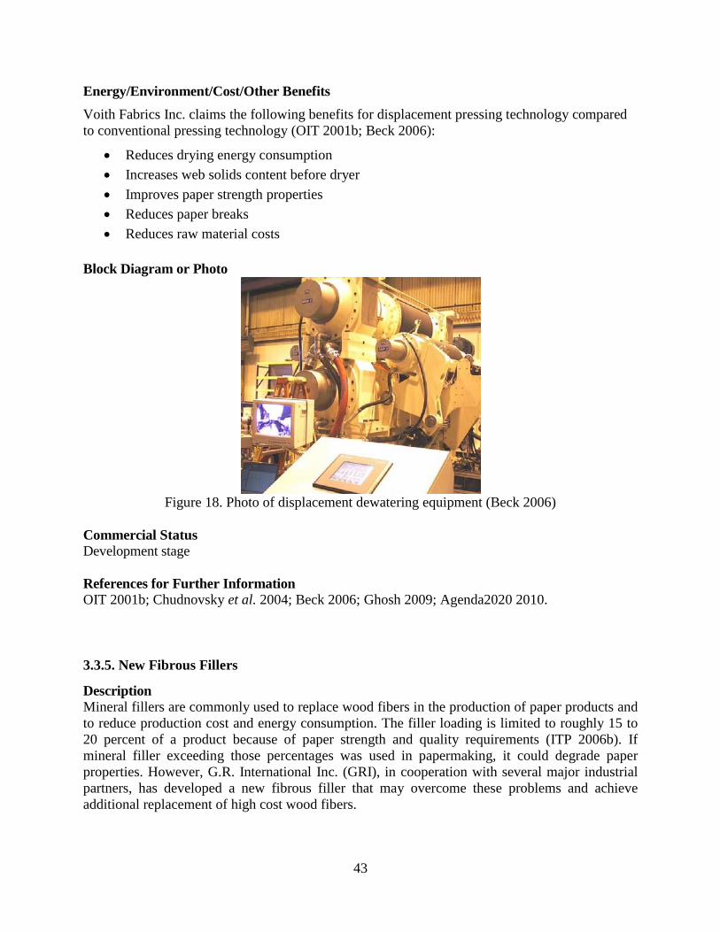
Figure 18. Photo of displacement dewatering equipment .............................................................. 43
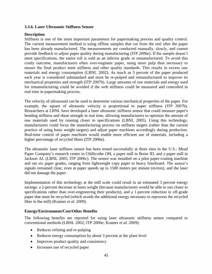
Figure 19. Laser ultrasonic stiffness sensor working principle ..................................................... 46
Figure 20. Photo of gas-fired dryer ................................................................................................ 48
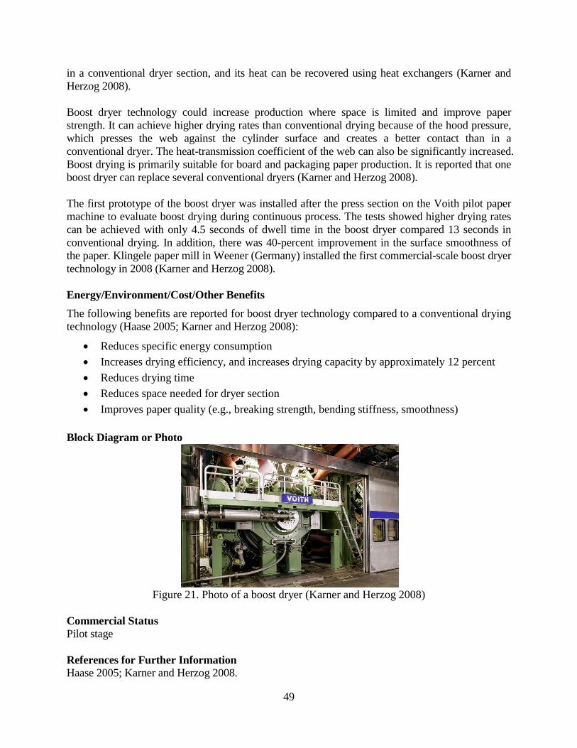
Figure 21. Photo of a boost dryer .................................................................................................. 49
Figure 22. Schematic of Condebelt drying process ....................................................................... 51
Figure 23. Paper machine with Condebelt drying ......................................................................... 51
Figure 24. Cross- and machine-direction oriented microwave drying .......................................... 53
Figure 25. Schematic of methanol production with BLG ............................................................... 55
Figure 26. Overview of BIGCC integrated with the pulp and paper mill ..................................... 58
Figure 27. Diagram of a hemicellulose extraction process ............................................................ 60
Figure 28. LignoBoost in chemical pulping plant ......................................................................... 62
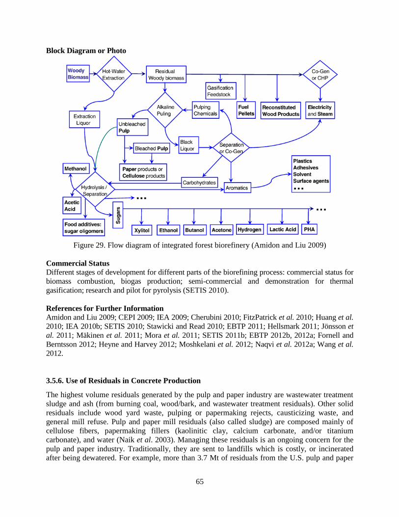
Figure 29. Flow diagram of integrated forest biorefinery.............................................................. 65
Figure 30. Schematic of TMC mechanism .................................................................................... 68
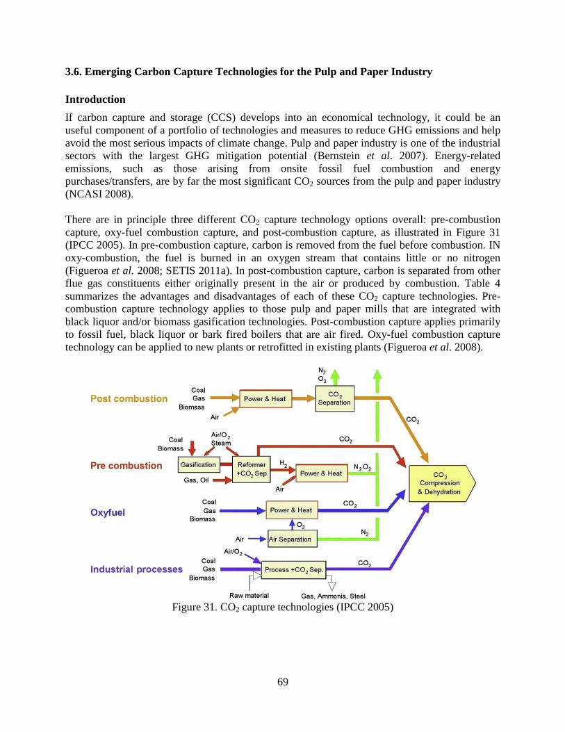
Figure 31. CO2 capture technologies ............................................................................................. 69
Figure 32. BLGCC with pre-combustion carbon capture .............................................................. 73
Figure 33. Biomass conversion with CO2 capture ......................................................................... 75
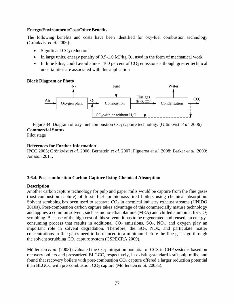
Figure 34. Diagram of oxy-fuel combustion CO2 capture technology .......................................... 77
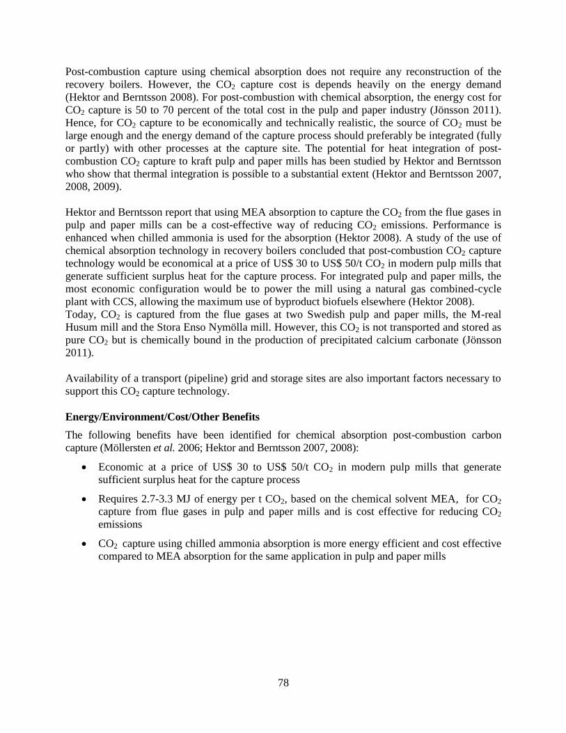
Figure 35. Two post-combustion carbon capture schemes for kraft pulp and paper mills ............ 79
Figure 36. CO2 Solution Inc. bio-technological CCS system ........................................................ 80
Figure 37. The main principles of the RMF PCC process ............................................................. 82
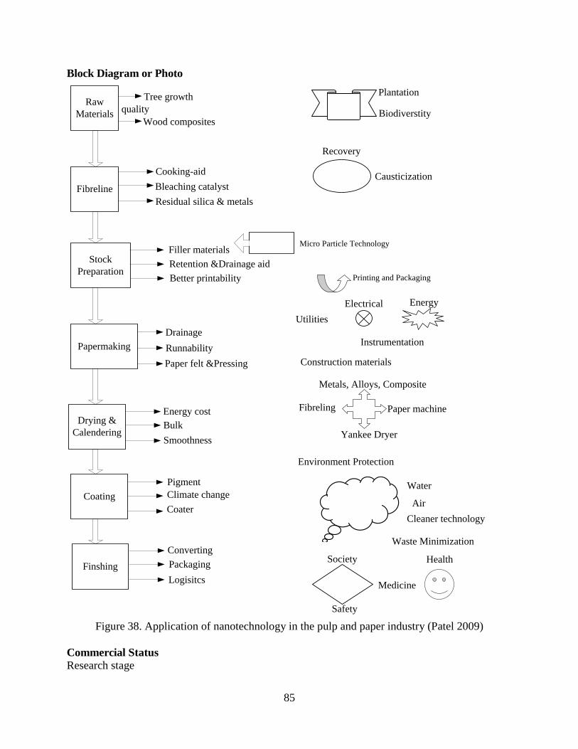
Figure 38. Application of nanotechnology in the pulp and paper industry ................................... 85
Page 9
Acronyms
Adt air dry tonne
ANL Argonne National Laboratory
BCP Beck cluster press
BLG black liquor gasification
BLGCC black liquor integrated gasification with combined cycles
BOD biological oxygen demands
CaCO3 calcium carbonate/limestone
CaO lime
Ca(OH)2 calcium hydroxide
CCS carbon capture and storage
CH4 methane
CHP combined heat and power production
CO carbon monoxide
CO2 carbon dioxide
COD chemical oxygen demand
DIP deinked pulp
DME dimethyl ether
D-GLU directed green liquor utilization
DS dry solids
EC European Commission
EJ exajoules
g gram
GHG greenhouse gas
GJ gigajoules
GRI G. R. International
GTI Gas Technology Institute
GWh gigawatt-hour
H2 hydrogen
H2O water
IEA International Energy Agency
IGCC integrated gasification combined cycle
IPCC Intergovernmental Panel on Climate Change
IPST Institute of Paper Science and Technology at Georgia Tech
IR infrared
kg kilogram
kWh kilowatt-hour
LBNL Lawrence Berkeley National Laboratory
LEF low-energy flotation
Page 10
m meter
MEA mono-ethanolamine
mm millimeter
Mt million tonnes
Mtoe million tonnes of oil equivalent
MWh megawatt hour
Na2S sodium sulfide
Na2CO3 sodium carbonate
NaOH sodium hydroxide
NOx nitrogen oxide
O2 oxygen
O3 ozone
OA oxalic acid
O&M operations and maintenance
ORNL Oak Ridge National Laboratory
PCC precipitated calcium carbonate
R&D research and development
RMF PCC recycled mineral filler precipitated calcium carbonate
RMP refiner mechanical pulping
SO2 sulfur dioxide
syngas synthetic gas
t tonne
TJ terajoules
TMC transport membrane condenser
TMP thermomechanical pulp
TiO2 titanium dioxide
tpd tonnes per day
Page 11
1
Emerging Energy-efficiency and Greenhouse Gas Mitigation Technologies for
the Pulp and Paper Industry
Lingbo Kong1, 2
, Ali Hasanbeigi1, Lynn Price
1
1 China Energy Group, Energy Analysis and Environmental Impacts Department
Environmental Energy Technologies Division
Lawrence Berkeley National Laboratory
2
State Key Laboratory of Pulp and Paper Engineering
South China University of Technology
1. Introduction
The pulp and paper industry accounted for approximately 5 percent of total industrial final energy
consumption and 2 percent of direct carbon dioxide (CO2) emissions1 from the industrial sector
worldwide in 2007 (IEA 2011). World paper and paperboard demand and production are increasing;
annual production is expected to grow from approximately 365 million tonnes (Mt) in 2006 to
between 700 Mt (low estimate) and 900 Mt (high estimate) in 2050. In 2010, the paper and
paperboard reached 394 Mt (FAOSTAT 2012). The largest share of this growth will take place in
China, India, and other developing countries (Figure 1) (IEA 2009). This significant increase in
paper production will cause a corresponding significant increase in the pulp and paper industry’s
absolute energy consumption and greenhouse gas (GHG) emissions.
Note: OECD is an acronym for the Organization for Economic Co-operation and Development
Figure 1. Annual world paper and paperboard production (IEA 2009)
Studies have documented the potential to reduce energy use and GHG emissions by
implementing commercially available energy-efficiency technologies and measures in the pulp
and paper industry worldwide (Worrell et al. 2001; Kinstrey and White 2006; IEA 2007; UNIDO
1 Direct CO2 emissions are emissions from fossil fuel use and chemical reactions produced onsite and do not include
emissions associated with purchased steam and electricity.
Page 12
2
2010b; Zafeiris 2010; IEA 2011). However, given the projected continuing increase in absolute
paper production, future reductions (e.g., by 2030 or 2050) in absolute energy use and CO2
emissions will require additional innovations. Innovations will likely include development of
different processes and materials for pulp and paper production or technologies that can
economically capture and store the industry’s CO2 emissions. The development of these emerging
technologies and their deployment in the market will be a key element in the pulp and paper
industry’s mid- and long-term climate change mitigation strategies.
Many studies from around the world have identified energy-efficiency technologies for the pulp
and paper industry that have already been commercialized and are sector-specific or cross-cutting
(Jaccard/Willis 1996; Alsema 2001; EC 2001; FOE 2005; ITP 2006c; NEDO 2008; Kramer et al.
2009; Bajpai 2010; EPA 2010; Zafeiris 2010; CEPI 2011b; ITP 2011c). However, information is
scarce and scattered regarding emerging or advanced energy-efficiency and low-carbon
technologies for the pulp and paper industry that have not yet been commercialized. This report
consolidates available information on emerging technologies for the pulp and paper industry with
the goal of giving engineers, researchers, investors, pulp/paper companies, policy makers, and
other interested parties easy access to a well-structured resource of information on this topic.
The information presented in this report is collected from publicly available sources. Although
the report covers the main emerging energy-efficiency and low-carbon technologies for the pulp
and paper industry, the list of emerging technologies addressed is not exhaustive.
We present information about the 36 technologies covered in this report using a standard
structure for each technology. First, we briefly describe the technology, including background,
theory, pros and cons, barriers and challenges, and case studies if available. Next, we present the
energy, environmental, and other benefits of the technology as well as cost information if
available. For most technologies, we include a block diagram or picture. Finally, we identify the
commercialization status of each technology along with resources for further information. The
commercialization status for each technology is as of the writing of this report and uses the
following categorization:
Research stage: the technology has been studied, but no prototype has been developed.
Development stage: the technology is being studied in the laboratory, and a prototype has
been developed.
Pilot stage: the technology is being tested at an industrial-scale pilot plant.
Demonstration stage: the technology is being demonstrated and tested at the industrial
scale in more than one plant but has not yet been commercially proven.
Semi-commercial stage: the technology is proven and is being commercialized but has a
very small market share.
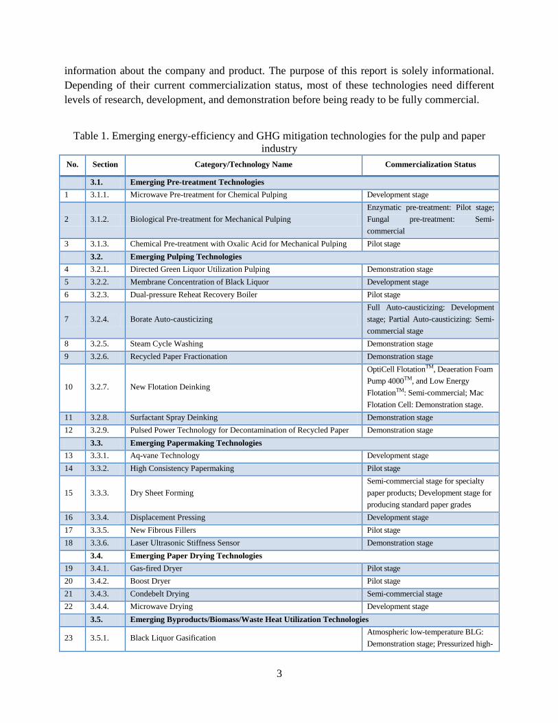
Table 1 lists the 36 technologies covered in the report. It is important to note that the nature of
emerging technologies is that many are proprietary and/or the primary source of information
about them is the manufacturers who are developing them. In some cases, we mention the names
of companies that are developing or providing a technology so that readers can obtain more
Page 13
3
information about the company and product. The purpose of this report is solely informational.
Depending of their current commercialization status, most of these technologies need different
levels of research, development, and demonstration before being ready to be fully commercial.
Table 1. Emerging energy-efficiency and GHG mitigation technologies for the pulp and paper
industry
No. Section Category/Technology Name Commercialization Status
3.1. Emerging Pre-treatment Technologies
1 3.1.1. Microwave Pre-treatment for Chemical Pulping Development stage
2 3.1.2. Biological Pre-treatment for Mechanical Pulping
Enzymatic pre-treatment: Pilot stage;
Fungal pre-treatment: Semi-
commercial
3 3.1.3. Chemical Pre-treatment with Oxalic Acid for Mechanical Pulping Pilot stage
3.2. Emerging Pulping Technologies
4 3.2.1. Directed Green Liquor Utilization Pulping Demonstration stage
5 3.2.2. Membrane Concentration of Black Liquor Development stage
6 3.2.3. Dual-pressure Reheat Recovery Boiler Pilot stage
7 3.2.4. Borate Auto-causticizing
Full Auto-causticizing: Development
stage; Partial Auto-causticizing: Semi-
commercial stage
8 3.2.5. Steam Cycle Washing Demonstration stage
9 3.2.6. Recycled Paper Fractionation Demonstration stage
10 3.2.7. New Flotation Deinking
OptiCell FlotationTM, Deaeration Foam
Pump 4000TM, and Low Energy
FlotationTM: Semi-commercial; Mac
Flotation Cell: Demonstration stage.
11 3.2.8. Surfactant Spray Deinking Demonstration stage
12 3.2.9. Pulsed Power Technology for Decontamination of Recycled Paper Demonstration stage
3.3. Emerging Papermaking Technologies
13 3.3.1. Aq-vane Technology Development stage
14 3.3.2. High Consistency Papermaking Pilot stage
15 3.3.3. Dry Sheet Forming
Semi-commercial stage for specialty
paper products; Development stage for
producing standard paper grades
16 3.3.4. Displacement Pressing Development stage
17 3.3.5. New Fibrous Fillers Pilot stage
18 3.3.6. Laser Ultrasonic Stiffness Sensor Demonstration stage
3.4. Emerging Paper Drying Technologies
19 3.4.1. Gas-fired Dryer Pilot stage
20 3.4.2. Boost Dryer Pilot stage
21 3.4.3. Condebelt Drying Semi-commercial stage
22 3.4.4. Microwave Drying Development stage
3.5. Emerging Byproducts/Biomass/Waste Heat Utilization Technologies
23 3.5.1. Black Liquor Gasification Atmospheric low-temperature BLG:
Demonstration stage; Pressurized high-
Page 14
4
No. Section Category/Technology Name Commercialization Status
temperature BLG: Pilot stage
24 3.5.2. Biomass Gasification
Different commercial status for
different biomass gasification concepts,
most of which are under pilot and
demonstration stage currently
25 3.5.3. Hemicellulose Extraction before Chemical Pulping Pilot stage
26 3.5.4. LignoBoost Pilot stage
27 3.5.5. Other Integrated Biorefinery
Commercial status for biomass
combustion, biogas production; semi-
commercial and demonstration for
thermal gasification; research and pilot
for pyrolysis
28 3.5.6. Use of Residuals in Concrete Production Pilot stage
29 3.5.7. Transport Membrane Condenser
Semi-commercial stage for industrial
boilers; Research stage for paper
machine dryer section
3.6. Emerging Carbon Capture and Storage Technologies for the Pulp and Paper Industry
30 3.6.1. BLGCC with Pre-combustion Carbon Capture Development stage
31 3.6.2. Biomass Conversion with Pre-combustion Carbon Capture Research stage
32 3.6.3. Oxy-fuel Combustion Technology Pilot stage
33 3.6.4. Post-combustion Carbon Capture Using Chemical Absorption Pilot stage
34 3.6.5. Bio-Technological Carbon Capture Development stage
35 3.6.6. CO2 Sequestration in Recycled Mineral Fillers Pilot stage
36 3.7. Nanotechnology in Pulp and Paper Production Research stage
Because the nature of emerging technologies is constant and rapid change, the information
presented in this report is also subject to change. If readers are aware of a new technology that is
not presented in this report or have updated information about a technology that is described in
this report, please contact the authors2.
2 Lingbo Kong: [email protected] ; Ali Hasanbeigi: [email protected]
Page 15
5
2. Description of Pulp and Paper Production
The pulp and paper industry produces various types of pulp from virgin materials (wood and non-
wood) and/or recycled materials (waste paper) that are subsequently processed into paper
products in either integrated or non-integrated mills. At an integrated mill, pulping and
papermaking processes are integrated at one production site. Non-integrated mills either
manufacture pulp that is then sold on the market or purchase pulp for their paper production (EC
2001).
Before pulping, the raw materials have to be prepared to break down fibrous materials into small
pieces and remove impurities. Pulp can be manufactured by chemical, mechanical, or semi-
chemical methods. Bleaching may be required depending on the paper produced; bleaching
entails a chemical reaction that removes additional lignin from brown pulp. In an integrated mill,
prepared pulp is pumped to beating and stock preparation processes where different kinds of
paper are manufactured; in a non-integrated pulp mill, the next step is pulp drying, which is also
done with excess pulp produced in integrated mills. The subsections below describe the process
by which pulp and paper are produced in more detail, with a focus on the energy and GHG
impacts.
2.1. Pulp and Paper Production Processes and Energy Use
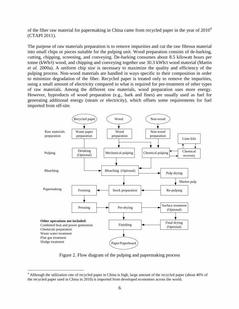
The major steps involved in manufacturing pulp and paper are: raw materials preparation, pulping,
chemical recovery, bleaching, pulp drying, and papermaking. Pulping and paper drying are the
most significant energy-consuming processes (Worrell et al. 2008). Figure 2 shows a flow
diagram of the entire pulping and papermaking process. The actual manufacturing process in a
pulp or paper mill varies depends on the raw materials employed and the paper products produced.
However, the basic principle of pulping and papermaking remains the same for all facilities.
Raw Materials Preparation
The raw materials for pulp making can be wood, non-wood, or recycled paper. Wood is the
primary source of cellulose fiber for paper products. Both softwood and hardwood are used. Non-
wood (e.g., straw, bagasse, and bamboo) is also used in some areas with limited access to forest
resources, especially in developing countries. Worldwide, non-wood materials make up about 6
percent of the total fiber supply for papermaking (IFC 2007). Waste paper has become another
important raw material for papermaking as technology from removing ink (deinking) has
developed. Using waste paper reduces the energy consumption of the process because recycled
paper only has to be treated to remove impurities whereas virgin fibrous materials require more
pre-treatment, digesting, and refining3. Current levels of paper recovering rate vary from 30
percent in the Russian Federation to more than 60 percent in Japan and Germany (IEA 2012). In
2011, 66.8 percent of all paper consumed in the U.S. was recovered for recycling (AF&PA 2012).
Note that not all the paper recycled in the U.S. is used domestically. Much of the recycled paper
is exported to China and is used as input to the Chinese pulp and paper mills. Nearly 63 percent
3 It should be noted that virgin paper production is critical to a functioning recycled paper sector. Without a constant
feed of virgin material, the supply of recycled paper would be exhausted in a short period of time.
Page 16
6
of the fiber raw material for papermaking in China came from recycled paper in the year of 20104
(CTAPI 2011).
The purpose of raw materials preparation is to remove impurities and cut the raw fibrous material
into small chips or pieces suitable for the pulping unit. Wood preparation consists of de-barking,
cutting, chipping, screening, and conveying. De-barking consumes about 8.5 kilowatt hours per
tonne (kWh/t) wood, and chipping and conveying together use 30.3 kWh/t wood material (Martin
et al. 2000a). A uniform chip size is necessary to maximize the quality and efficiency of the
pulping process. Non-wood materials are handled in ways specific to their composition in order
to minimize degradation of the fiber. Recycled paper is treated only to remove the impurities,
using a small amount of electricity compared to what is required for pre-treatment of other types
of raw materials. Among the different raw materials, wood preparation uses more energy.
However, byproducts of wood preparation (e.g., bark and fines) are usually used as fuel for
generating additional energy (steam or electricity), which offsets some requirements for fuel
imported from off-site.
Wood Non-woodRecycled paper
Mechanical pulping Chemical pulping
Wood
preparation
Non-wood
preparation
Bleaching (Optional)Pulp drying
Chemical
recovery
Stock preparation
Paper/Paperboard
Waste paper
preparationLime kiln
Deinking
(Optional)
Raw materials
preparation
Pulping
Papermaking
Bleaching
Forming
Pressing
Final drying
(Optional)Finishing
Surface treatment
(Optional)Pre-drying
Market pulp
Re-pulping
Other operations not included:
Combined heat and power generation
Chemicals preparation
Waste water treatment
Flue gas treatment
Sludge treatment
Figure 2. Flow diagram of the pulping and papermaking process
4 Although the utilization rate of recycled paper in China is high, large amount of the recycled paper (about 40% of
the recycled paper used in China in 2010) is imported from developed economies across the world.
Page 17
7
Pulping
Cellulose is the fibrous substance found in plant cells that are used to make pulp and paper; lignin
acts as an adhesive holding the fibers together. The primary purpose of pulping is to separate
fibers from lignin through chemical or mechanical measures to make the fibers suitable for
papermaking. There are three types of pulping technologies: chemical (soda, sulfate/kraft, or
sulfite), mechanical (e.g., SGW, RMP, TMP, or CTMP5
), and semi-chemical pulping
technologies. The pulping method employed in a given mill depends on the raw materials, the
desired pulp properties, and the type of paper produced. Of the three types, chemical pulping is
the most common pulping process. Globally, about 75 percent of wood pulp was produced with
chemical pulping technology in 2010 (FAOSTAT 2012).
Chemical pulping relies on chemical reaction in an aqueous chemical solution and high
temperature (thermal energy) to separate fibers by softening and dissolving the lignin that holds
them together. Approximately 80 percent of the world pulp production worldwide uses the kraft
process due to its advantages over the other methods (EC 2012). Mechanical pulping separates
the fibers by physical treating method such as refining or grinding; the lignin remains in the pulp.
Semi-chemical pulping is a combination of chemical and mechanical pulping in which wood
chips are subjected to a mild chemical digestion process before being mechanically pulped.
Generally, chemical pulping has a lower yield (45-55 percent) but higher pulp quality than
mechanical pulping; the pulp quality and yield from semi-chemical pulping fall in between the
quality and yield from the other two processes. Chemical pulping consumes 7.5-16.5 gigajoules
(GJ) of thermal energy per tonne of air dried pulp (steam for producing electricity not included)
and 550-900 kWh of electricity per tonne of pulp (EC 2012). Mechanical pulping processes are
electricity intensive. The specific energy consumption in mechanical pulping is 1000-4300
kWh/Adt pulp for different mechanical pulping methods (SGW, RMP, TMP, or CTMP) (EC 2012).
Pulping process is the second most energy-intensive process in the pulp and paper industry after
the paper drying process.
When recycled paper is used as raw material, bales of waste paper are conveyed to pulpers and
mixed with water via rotors or agitators that turn it into wet slurry. If deinking is required, the
most commonly used process is flotation, in which chemicals are added during pulping that
remove the hydrophobic ink from the fiber (as well as “stickies” – adhesives and other sticky
products found in waste paper) and keep the ink particles suspended in the slurry. During the
deinking process, the adsorption of dispersant and frother on fiber surfaces may reduce fiber-fiber
bonding and create foaming problems in paper machines. The production of recycled paper pulp
consumes 10 to 13 GJ less energy per tonne than the production of virgin pulp, depending on
whether it is de-inked and whether it replaces mechanical or chemical pulping of other raw
materials (IEA 2012). Schumacher and Sathaye (1999) report that producing paper from waste
paper requires 40 to 60 percent less energy than producing paper from wood (Schumacher and
Sathaye 1999).
Chemical Recovery
Chemical recovery is an important element for kraft/sulfite pulping process because it regenerates
the pulping chemicals and energy from what is known as black/red liquor. Black/Red liquor is the
5 SGW = stone groundwood pulp, RMP = refiner mechanical pulp, TMP = thermomechanical pulp, and CTMP =
chemi-thermomechanical pulp.
Page 18
8
solution of residues from cooking or digesting raw materials to free the cellulose fibers in
kraft/sulfite pulping process, which mainly include cooking chemicals and combustible
component dissolved from raw materials, such as lignin and hemicellulose. The chemicals
recovered from black liquor are reused in subsequent pulping. In addition, a large amount of
energy can be generated by combusting the black liquor in recovery boilers. Chemical recovery is
essential to the cost-effective operation of kraft pulp mills and is used in more than 80 percent of
the U.S. wood pulp production (DOE 2005a).
Chemical recovery typically starts with brown stock washing of the pulp, followed by black
liquor evaporation. This step uses the largest amount of steam in a kraft mill, about 2.2 to 5.4 GJ/t
pulp (DOE 2005a). After being concentrated through evaporation and/or additional concentration
operation, black liquor is sent to the recovery boiler for recovering the chemicals and energy by
combustion. The recovery boiler uses an estimated 1.2 to 4.2 GJ/t pulp of fuel and electricity for
furnace auxiliaries. However, the boiler also produces 9 to 15 times as much energy in the form
of heat (Martin et al. 2000a). Roughly 22 GJ of black liquor can be combusted per tonne of pulp
(IEA 2007). A large modern chemical pulp mill could be self-sufficient in energy terms, using
only biomass and delivering surplus electricity to the grid (IEA 2011). After the black liquor is
evaporated and combusted, the green liquor (the molten inorganic smelt formed in the recovery
boiler with wash water) is causticized to regenerate pulping chemicals (white liquor) for the next
digesting process. Lime kiln is an integral part of the chemical recovery system at kraft pulp mills.
The lime mud (CaCO3) exhausted from the causticizers will be calcined or reburned in lime kilns
where CaCO3 is converted back into lime (CaO) for reuse in the recausticing process (Miner and
Upton 2002). Large amount of energy is used in lime kilns with high levels of process-related
CO2 emissions6.
Bleaching and Pulp Drying
Bleaching is required for producing paper products with higher brightness such as printing and
writing papers. The chemical reactions involved in bleaching remove the remaining lignin from
the pulp. The most common bleaching chemicals are, chlorine dioxide, sodium hydroxide
(NaOH), hydrogen peroxide, oxygen (O2), ozone (O3), and hypochlorite. Environmental concerns
about chlorinated organic byproducts from elemental chlorine and its derivatives have driven the
industry toward the development and use of elemental chlorine-free and totally chlorine-free
bleaching technologies (DOE 2005a). Chemical pulp can be bleached to a greater extent because
of its lower lignin content than mechanical pulp. The bleaching process is heat intensive but
consumes only a small amount of electricity. The heat requirements range from 0.4 to 3.2 GJ/t
pulp, and electricity requirements range from 60 to 185 kWh/t pulp (DOE 2005a).
In standalone pulp mills, the beached/unbleached pulp is pumped to pulp drying process. While
the bleached/unbleached pulp is pumped to beating and stock preparation process directly for
papermaking in integrated mills. Also, the pulp must be dried before transport to the paper mill in
standalone mills. Pulp drying is an energy-intensive process that typically uses 4.5 GJ/t pulp of
thermal energy and 155 kWh/t pulp of electricity (Martin et al. 2000a). The large amount of
6 Note the emissions from kraft pulp mill lime kilns contain both biomass and fossil carbon. The process-related CO2
emissions that released from calcium carbonate originate in the wood chips and, generally, biomass based carbon are
not included in GHG inventories (Miner and Upton 2002).
Page 19
9
energy expended for pulp drying can be saved by integrating pulp and paper production into a
single mill.
Papermaking
Papermaking is a process for laying pulp fibers uniformly in a planar web followed by a massive
dehydration process. No matter what type of pulp is used or what type of paper is produced, the
basic papermaking procedure follows the steps shown in Figure 2: beating and stock preparation,
forming, pressing, drying, and finishing.
Beating and stock preparation process is an important intermediate step between the pulp and
paper production lines and determines the final properties of the paper product. In this process,
the pulp is refined or beat, blended, and screened to separate and clean the fibers. The stock
consistency pumped to the headbox is about 0.2 to 1.0 percent (2-10 g fiber per kg water). Next,
the stock is pumped to the paper machine through stock approach system. The headbox is
employed to dispense the stock evenly onto fabric mesh spanning the entire width of the paper
machine to form a paper web. A large amount of water within the stock is removed from the web
by drainage and vacuum thickening in the forming section, after that a wet-sheet is formed. At the
end of the forming process, the wet-sheet contains about 75 to 85 percent water. The wet-sheet
then moves to the press section for dewatering by mechanical compression. The wet-sheet leaves
the press section into the dryer section with water content of 45 to 67 percent, depending on the
paper grade and press section design (Karlsson 2000). In the subsequent drying process, the
remaining water is removed from the wet-sheet by evaporation. The final paper moisture content
after the dryer section is 2 to 9 percent. Many types of paper also undergo surface treatments to
improve printability and to add functional properties. Paper finishing is the last operation, which
includes calendering, reeling, winding, trimming, roll wrapping and handling, and sheet finishing.
Papermaking is the most capital- and energy-intensive process in the pulp and paper industry. In
addition to the electricity used for driving paper machine, various pumps, fans, motors, and
conveyors, the process also uses thermal energy to dry paper. The paper drying process accounts
for about 67 percent of the total energy required in papermaking, equivalent to 25 to 30 percent of
the total energy used in the pulp and paper industry (IEA 2009). The electricity used for beating
and stock preparation depends on the paper type and varies from 60 to 1,200 kWh/t paper (IEA
2007). The typical heat consumption for paper drying is 3 to 6 GJ/t paper, and electricity usage is
450 to 1,100 kWh/t paper (EC 2001). It should be noted that the energy consumption of the
papermaking process varies greatly according to the pulp quality, paper grade produced, and
technologies employed, etc.
Page 20
10
2.2. GHG Impact of the Pulp and Paper Industry
GHG emissions from the pulp and paper industry are predominantly CO2 with smaller amounts of
methane (CH4) and nitrous oxide (N2O) (EPA 2009). The pulp and paper industry ranks fourth in
terms of energy consumption among industries worldwide; however, it is one of the least CO2-
intensive industrial sectors because many plants utilize a significant percentage of biomass,
although large variations exist among countries depending on biomass availability and industrial
structure. Globally, the pulp and paper industry meets approximately 33 percent of its total
energy use needs with biomass (IEA 2010a). In Organization for Economic Cooperation and
Development (OECD) countries, biomass supplies 53.6 percent of energy use in the pulp and
paper industry (WBCSD 2011). The U.S. pulp and paper industry gets more than 65 percent of
energy from biomass (EIA 2011; AF&PA 2012). Note that CO2 emissions from biomass fuels are
considered carbon neutral by the Intergovernmental Panel on Climate Change (IPCC) (IPCC
2006). The widely use of biomass is the primary reason for the difference in CO2 intensity
between the paper industry and other industrial sectors. For some types of paper, pulp and paper
can be produced without CO2 emissions theoretically if residues were used efficiently (IEA 2007).
The GHG emissions involved in the pulp and paper industry consist of direct and indirect
emissions. Direct emissions are from combustion of fossil fuels onsite and also include non-
energy-related emissions such as CO2 emissions from chemical reactions in lime kilns and CH4
emissions from mill landfills and wastewater treatment operations. Indirect emissions are
associated with off-site generation of steam and electricity that are purchased by or transferred to
the mill. Of these GHG emissions sources, energy-related emissions, such as those arising from
onsite fossil fuel combustion and energy purchases/transfers, are by far the most significant
(NCASI 2008). Table 2 details the industry’s direct GHG emissions sources (EPA 2009, 2010).
Non-integrated paper mills emit more GHG emissions than integrated mills per unit of production
because the availability of biomass is limited in these non-integrated (or fully recycled) paper
mills; thus, the majority of CO2 emissions from these mills are likely to be generated from fossil
fuel consumption.
Table 2. Direct GHG emissions sources in the pulp and paper industry (EPA 2009, 2010)
GHG emissions source Types of pulp/paper mill where
emissions source located Types of GHG emissions
Fossil fuel/Biomass-fired boilers All types of pulp/paper mills CO2, biogenic CO2, CH4, N2O
Thermal oxidizers (TOs) /
Regenerative TOs
Kraft/Semi-chemical pulp mills CO2, CH4, N2O
Direct-fired turbines/dryers Gas-fired turbines/dryers in some
mills
CO2, CH4, N2O
Chemical recovery boilers Kraft/Sulfite/Soda pulp mills CO2, biogenic CO2, CH4, N2O
Lime kilns Kraft/Soda pulp mills CO2, process/biogenic CO2, CH4,
N2O
Make-up chemicals Kraft/Soda pulp mills process CO2
Flue-gas desulfurization systems Mills that operate coal-fired
boilers are required to limit sulfur
dioxide emissions
process CO2
Anaerobic wastewater treatment All types of pulp/paper mills biogenic CO2, CH4
Onsite landfills All types of pulp/paper mills biogenic CO2, CH4
Page 21
11
3. Emerging Energy-Efficiency and GHG Mitigation Technologies for the Pulp and Paper
Industry
The subsections below describe emerging technologies that are claimed to be able to reduce
energy consumption and GHG emissions associated with pre-treatment, pulping, and
papermaking, technologies related to utilize byproducts and biomass, carbon capture as well as
nanotechnologies applicable to the pulp and paper industry.
3.1. Emerging Pre-treatment Technologies
The subsection describes three emerging wood chip pre-treatment technologies: microwave,
biological, and chemical (oxalic acid), which are applied prior to the pulping process and improve
the energy efficiency of that process.
3.1.1. Microwave Pre-treatment for Chemical Pulping
Description
In traditional chemical pulping, most of the energy and chemicals are used for driving the
chemical reactions in wood chips to cleave covalent bonds between fibers during pulping process.
Microwave pre-treatment technology alters the cellular microstructures that control permeability in
wood so that the pulping chemicals can pass more easily to the center of the chips, which reduces
both the amount of energy and chemicals needed for the pulping process (DOE 2005b).
Microwave pre-treatment reduces the amount of energy required for chemical pulping because it
lowers the H-Factor required to meet target performance characteristics, which is a measure of the
relative speed of delignification in pulping process. Microwave pre-treatment can also result in
decreased lime kiln fuel consumption because fewer chemicals are needed for the pulping process.
It is claimed that microwave pre-treatment could decrease chemical usage and H-Factor by around
40 percent while still producing pulp with acceptable quality through breaking the cellular
microstructures which control permeability in wood (Compere 2006). The technology also allows
pulping chemicals to pass easily into larger and more diverse-sized wood chips, such as four-inch-
long by four-inch-diameter hardwoods (ITP 2011c). Hemicellulose removal from black liquor
could decrease viscosity and increase solids, correspondingly reduces the energy required for black
liquor concentration (Compere 2006). However, microwave pre-treatment will increase the
electricity use at the mill significantly. Also, it may results in potential damage to pulp fibers and
loss of paper strength.
Microwave pre-treatment technology can be retrofitted into existing kraft, soda, sulfite, and other
chemical pulp mills to increase both pulp yield and energy efficiency, and minimize chemical usage
(ITP 2007a). In the U.S., it is estimated that the market for this technology will be up to 75 percent
of chemical pulp mills (ITP 2007a). Assuming 55 million tonnes per year of chemical pulp in the
U.S. pulp and paper industry, annual energy savings could be as much as 116,050 terajoules (TJ)
(Compere 2006).
Page 22
12
Energy/Environment/Cost/Other Benefits
Some of the claimed benefits of microwave pre-treatment technology compared to conventional
pre-treatment technology are (OIT 2001a; DOE 2005b; Compere 2006; ITP 2007a):
Reduces energy use for chemical pulping
Decreases lime kiln energy use
Reduces energy required for black liquor concentration
Improves pulp yield and throughput by 40 percent in existing kraft pulp mills
Reduces pulping chemicals and H-factor by 40 percent
Decreases temperature required to produce a given quality of pulp
Increases recovery boiler throughput
Has a capital cost of about $25 million for a 1,000 air-dry-tonne (Adt) mill with payback
shorter than 2 years
Block Diagram or Photo
Not Available
Commercial Status
Development stage
References for Further Information OIT 2001a; DOE 2005b; Compere 2006; ITP 2007a, 2010, 2011c.
3.1.2. Biological Pre-treatment for Mechanical Pulping
Description
In the mechanical pulping process, cellulose fibers are usually separated in a grinder or refiner by
means of mechanical force applied to the wood matrix. Mechanical pulping is one of the most
electricity-intensive processes in the pulp and paper industry, consuming 2 to 3.5 megawatt hours
(MWh) of energy per tonne pulp, depending on raw material and process conditions (ETEPS 2007).
A rough estimate of the international best practice average electricity consumption for mechanical
pulping is 2.75 MWh/tonne pulp (CAI/BECE 2009). Only a portion of the electricity used in
grinders or refiners is converted into the mechanical work to liberate the fibers; the rest is converted
to heat through friction. Although some of the heat produced in mechanical pulping is recovered
and reused, biological pre-treatment of wood chips before refining could significantly reduce the
energy requirement for mechanical pulping.
Biological pre-treatment uses fungus or enzymes to modify the cellular structure of wood chips.
The purpose is to decrease energy consumption by modifying the cell wall of fibers and changing
its external environment to enhance refining without jeopardizing pulp quality (Viforr 2008).
Although biotechnology has successfully been used in other phases of the pulp and paper
production process, it has been challenging in the wood chips pre-treatment because of size
incompatibility between the molecules of enzymes and the dimensions of pores (Bajpai 2012).
Page 23
13
The two common biological pre-treatment technologies used on wood chips in mechanical pulping
are fungal and enzymatic. Fungal pre-treatment was implemented on a conventional mechanical
pulping line in Wisconsin (U.S.) that produced 220 tonnes per day (tpd), reducing energy costs by
33 percent from 121$/tonne to 81$/tonne (Swaney et al. 2003a). Biological pre-treatment also
improves fiber strength and reduces pitch content. However, it will increases bleaching chemical
consumption. Because biological pre-treatment is an additional operation, operations and
maintenance (O&M) costs also increase compared to costs of mechanical pulping without
biological pre-treatment. But the overall costs of mechanical pulping with biological pre-treatment
technology are lower than the costs without biological pre-treatment because of the large amount of
energy saved with biological pre-treatment. A case study conducted by Swaney et al. (2003a)
shows the net cost savings are about 18 $/t of furnish pulp at the mill studied in Wisconsin.
Economic analyses indicate that fungal pre-treatment is both technologically feasible and
economically beneficial (Kramer et al. 2009). The fungal pre-treatment of wood chips prior to
mechanical pulping has also been scaled up and demonstrated at a TMP mill in Brazil (Swaney
2002).
Enzymatic pre-treatment of wood chips uses one or more enzymes such as cellulase, hemi-
cellulase, xylanase, pectinase, or laccase (Wang et al. 2007). The cellulase, xylanase, and
pectinase pre-treatments have been tested jointly by several partners (including KCL, STFI-
Packforsk, CTP, VTT, Holmen Paper, Stora Enso, UPM-Kymmene and Metso) that use different
types of equipment. Use of xylanase resulted in the greatest energy savings: a 25-percent decrease.
Cellulase pre-treatment resulted in a 20-percent energy reduction, and pectinase pre-treatment
reduced energy usage by 10 percent compared to refining without enzymatic pre-treatment
(Viforr 2008). The main drawback of all enzymatic treatments is that they decrease fiber length.
More work is needed to optimize the process and demonstrate its maximum potential before
commercialization.
Energy/Environment/Cost/Other Benefits
The following benefits and costs have been identified for mechanical pulping with biological
(fungal and enzymatic) pre-treatment:
a) Fungal pre-treatment
Saves 25 to 40 percent of refining energy compared to conventional refining without
biological pre-treatment (Scott et al. 1998)
Improves paper quality, e.g., enhanced paper strength and reduced pitch content
Extends refiner lifetime
b) Enzymatic pre-treatment
Pectinase pre-treatment of wood chips – saves up to 20 percent of refining process energy
(Peng et al. 2005)
Xylanase pre-treatment of hardwood chips – saves up to 26 percent of refining process
energy (Girard et al. 2006)
Using cellulase and cellulase mixture pre-treatment of softwood chips – possibly reduces
refining energy use by up to 20 percent (Pere et al. 2007)
Enzymatic pre-treatment generally – possibly reduces refining energy by 10 to 25 percent
reduction in refining energy consumption is possible when using enzymatic pre-treatment
(ECOTARGET 2009)
Page 24
14
Block Diagram or Photo
Figure 3. Enzymatic pre-treatment of wood chips for mechanical pulping (ECOTARGET 2009)
Commercial Status
a) Fungal pre-treatment
Semi-commercial stage
b) Enzymatic pre-treatment
Pilot state
References for Further Information
Scott et al. 1998; Swaney 2002; Swaney et al. 2003a; Peng et al. 2005; Girard et al. 2006;
ETEPS 2007; Pere et al. 2007; Wang et al. 2007; Viforr 2008; CAI/BECE 2009; ECOTARGET
2009; Kramer et al. 2009; Bajpai 2012.
3.1.3. Chemical Pre-treatment with Oxalic Acid for Mechanical Pulping
Description
Similar to the biological pre-treatment technology explained above, chemical pre-treatment, which
includes oxalic acid (OA) treatment, acid leaching, and electrochemically treated salt solutions, can
be used on wood chips to enhance the process of separating fibers (known as defibration) and
refining efficiency in mechanical pulping (ECOTARGET 2009). Chemical pre-treatment of wood
chips can significantly reduce the energy consumed in the refining process and does not adversely
affect the final paper product; under optimized conditions, chemical pre-treatment can improve
web strength and paper brightness (Li et al. 2011).
OA pre-treatment is incorporated in a mechanical pulping in a manner similar to traditional
chemical pre-treatments (Swaney et al. 2003b). BioPulping International Inc. of Wisconsin (U.S.)
developed OA pre-treatment technology jointly with several industrial and university partners (ITP
2010). Brief pre-treatment of different types of wood chips using 0.05 to 6 percent of a dilute OA
Page 25
15
solution can reduce the electricity used in mechanical pulping by 20 to 30 percent compared to the
amount used in conventional pulping without pre-treatment (Akhtar et al. 2007). In addition, OA
pre-treatment improves paper strength and reduces resin content by approximately 30 percent prior
to pulping (ITP 2011c).
A pilot-scale trial of OA pre-treatment at the Andritz pilot plant in Springfield OH (U.S.) reduced
refiner energy use by approximately 25 percent. The expected payback period is 2 years or shorter,
which makes this technology financially attractive (ITP 2010). The pilot trials conducted at the
Forest Products Laboratory in Madison, WI (USA) shows that a combined oxalic acid/bisulfite
treatment resulted in 21 percent refiner energy savings and 13 percent increase in brightness for
aspen (Houtman and Horn 2011). The OA pre-treatment technology also removes hemicellulose,
which can be directly in polymeric form for novel industrial applications such as biopoloymers,
hydrogels, thermoplystic xylan derivative, or source of sugars for fementation to fuels (Bajpai
2012). However, OA pre-treatment increases consumption of bleaching chemicals. In addition, it
will result in pulp yield and brightness loss. The O&M costs of mechanical pulping also increase
because of the added OA pre-treatment unit.
ECOTARGET7 research results show that chemical pre-treatment with oxalate has the largest
energy saving potential among chemical pre-treatment methods; the other methods resulted in
only minor energy savings (although they might show additional potential after further studies)
(ECOTARGET 2009). Overall, chemical pre-treatment reduced energy use by 0 to 25 percent
compared to the energy used in conventional mechanical refining.
Energy/Environment/Cost/Other Benefits
The following benefits and costs have been identified for mechanical pulping with OA chemical
pre-treatment (Swaney et al. 2003b; ITP 2010; Houtman and Horn 2011; ITP 2011c):
Reduces refiner energy use by 20 to 30 percent
Reduces resin content by 30 percent prior to pulping
Greatly improves paper strength
Has payback period of 2 years or shorter
Improves dewatering efficiency
7 The largest research project ever in the European pulp and paper industry, funded by the European Commission
Page 26
16
Block Diagram or Photo
Chipping Washing TMP Refining Pulp Bleaching
DebarkedWood
Chemical Pulp Other
Furnish
Atmos. Presteaming
OA Solution
Steam
OA Pretreatment
Impregnation
Steam
OA Reaction Vessel
Deimpregnation
Figure 4. Chemical pre-treatment using OA in TMP mill (Swaney et al. 2003b)
Commercial Status
Pilot stage
References for Further Information Swaney et al. 2003b; Akhtar et al. 2007; ECOTARGET 2009; ITP 2010; Houtman and Horn
2011; ITP 2011c; Li et al. 2011.
Page 27
17
3.2. Emerging Pulping Technologies
The subsections below describe the following nine emerging technologies that can save energy
and reduce CO2 emissions in the pulping process: directed green liquor utilization, membrane
concentration of black liquor, dual-pressure reheat recovery boiler, borate auto-causticizing,
steam cycle washing, recycled paper fractionation, new flotation deinking, surfactant spray
deinking, and pulsed power technology for decontaminating recycled paper.
3.2.1. Directed Green Liquor Utilization Pulping
Description
Green liquor is the partially recovered form of kraft pulping liquor. It is a dissolved smelt of
sodium carbonate (Na2CO3) and sodium sulfide (Na2S) from the recovery boiler in kraft mill.
Normally, green liquor is used to react with lime (CaO) in a process called causticizing to
produce calcium carbonate (CaCO3) and regenerate white liquor (a mixture of NaOH and Na2S),
which is reused in chemical pulping process (Naqvi et al. 2010). Green liquor is naturally rich in
hydrosulfide ions, which can accelerate pulping and provide a high-value product (ITP 2011c).
Using green liquor as a pre-treatment in conventional kraft pulping can reportedly result in pulps
with substantially higher viscosities and strengths (Andrews et al. 1985).
Directed green liquor utilization (D-GLU) pulping is based on the reuse of green liquor for pre-
treatment of wood chips prior to kraft pulping. Different from the conventional kraft pulping
process in which all the green liquor is used to regenerate white liquor, this new pulping
technology redirects 20 to 30 percent of the green liquor from the causticizing process to pulp
pre-treatment before cooking in the digester. As a result, not only the lime kiln load but also the
energy consumption of the digester can be reduced.
North Carolina State University and the Georgia Institute of Technology performed laboratory-
scale pulping and fiber analyses for some kraft mills (e.g., Evergreen Pulp mill, Temple-Inland
mill, and Evadale pulp mill) as support for mill trials of the D-GLU pulping process (ITP 2006c).
Green liquor use of this type has also been demonstrated in pulp mills in Finland and can
reportedly increase pulp yields, produce higher fiber strength, reduce digester alkali demand,
reduce lime kiln load by up to 30 percent, increase the bleachability of pulp, and reduce energy
use by up to 25 percent (ITP 2011b). Compared to conventional kraft pulping, D-GLU pulping
saves almost 50 percent alkali, and more than doubles pulp viscosity at the similar Kappa number
with higher pulp yield (Lucia 2005).
Implementation of D-GLU pulping is straightforward and requires minimal capital investment.
Energy savings are the main driver for implementation of this technology. Among the potential
negative impacts are that green liquor pulping might reduce the heat value of black liquor and
increase black liquor dead load (Lucia 2006). A full-scale trial performed at Evadale pulp mill in
Texas increased levels of rejects from the digester and decreased screened yield (Malmberg Aug.
2012). Environmental and scaling issues related to nitrogen emissions during recovery (because of
the inclusion of organic additive), higher sulfide off-gassing during pulping, and build-up of scale
in the digester and/or evaporators are other issues associated with this technology that need further
investigation.
Page 28
18
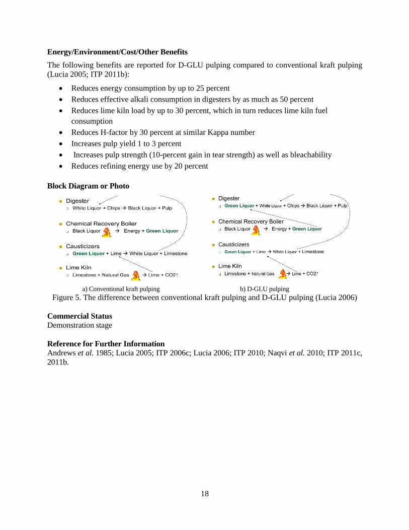
Energy/Environment/Cost/Other Benefits
The following benefits are reported for D-GLU pulping compared to conventional kraft pulping
(Lucia 2005; ITP 2011b):
Reduces energy consumption by up to 25 percent
Reduces effective alkali consumption in digesters by as much as 50 percent
Reduces lime kiln load by up to 30 percent, which in turn reduces lime kiln fuel
consumption
Reduces H-factor by 30 percent at similar Kappa number
Increases pulp yield 1 to 3 percent
Increases pulp strength (10-percent gain in tear strength) as well as bleachability
Reduces refining energy use by 20 percent
Block Diagram or Photo
a) Conventional kraft pulping b) D-GLU pulping
Figure 5. The difference between conventional kraft pulping and D-GLU pulping (Lucia 2006)
Commercial Status
Demonstration stage
Reference for Further Information Andrews et al. 1985; Lucia 2005; ITP 2006c; Lucia 2006; ITP 2010; Naqvi et al. 2010; ITP 2011c,
2011b.
Page 29
19
3.2.2. Membrane Concentration of Black Liquor
Description
In most modern pulp mills, the large amount of black liquor is concentrated in multiple effect
evaporators, followed by incineration, smelting and causticization to recover 85 percent of the
cooking chemicals (Bhattacharjee et al. 2006). Black liquor evaporation accounts for
approximately 12 percent of the energy used in pulping and papermaking process (Kinstrey and
White 2006). To improve energy efficiency of evaporation, the weak black liquor (the black
liquor with lower solids content) usually have to be concentrated using steam to raise the solids
content. However, the steam use efficiency of evaporation could be improved further if
membrane technology were used to pre-evaporate the weak black liquor instead of the currently
used steam-heated concentrator.
Membrane technology concentrates high molecular weight solids from low molecular weight
fraction of weak black liquor. The most utilized membrane technologies in the pulp and paper
industry are microfiltration (MF), ultrafiltration (UF), nanofiltration (NF), and reverse osmosis (RO)
(Dillard 1998). These technologies use pressure gradient to separate the liquid stream through a
porous or semi-permeable membrane as two liquid stream (Dillard 1998). After membrane process,
the concentrated black liquor could achieve higher solids content. Membrane technology has a
broad range of separation capability at molecular level. The membranes used in black liquor
concentration are classified according to pore size. The pore size of MF membrane ranged from a
few microns to 0.1 microns (μm), UF membrane pore size is between 0.1μm and 0.01μm, NF
membrane is ranging from 0.01μm to 0.001μm, and RO membrane is less than 0.001μm (Adnan et
al. 2010). RO membranes only allowed water molecular passed through under extremely high
pressure drops (10-100 MPa) compared to other membrane technologies mentioned above (Dillard
1998).
UF membranes have been operating since 1980s to separate color, BOD, COD, and AOX from
caustic effluents (Dillard 1998). The background, research, development and applications of
membrane technologies including MF, NF, UF, and RO in different areas of the pulp and paper
industry are surveyed by Adnan and coworkers (Adnan et al. 2010). UF has so far been employed
mainly for the following three purposes: separation of lignin compounds from low molecular
weight inorganic fraction; fractionation of high molecular weight lignin compounds; and recovery
of water (Bhattacharjee and Bhattacharya 2006). Many studies have been conducted to investigate
UF membrane technology for treating black liquor to recovery the valuable organics (Dafinov et al.
2005; Holmqvist et al. 2005; Wallberg et al. 2005; Bhattacharjee et al. 2006; Jönsson and Wallberg
2009). Most of these applications are still in the laboratory stage. The solids content of weak black
liquor could be concentrated to over 30 percent using UF membrane technology (Wallberg et al.
2005).
One of the drawbacks in the utilizing of membrane technology for black liquor pre-evaporation is
the marked decline of permeate flux and associated fouling problems (Bhattacharjee and
Bhattacharya 2006). The membranes must be operated at very high pH conditions (Sholl 2011). In
addition, capital and operating costs are high, but improvements are being made in membranes and
process equipments. Fouling and successful cleaning are of great importance if membrane
technology for black liquor concentration is to be implemented on an industrial scale (Wallberg et
al. 2003).
Page 30
20
The U.S. DOE’s Innovative Manufacturing Initiative announced in June 2012 for development of
highly durable membrane coating for black liquor concentration process with US$2.6 million award,
led by Teledyne Scientific & Imaging, LLC (TS&I) in partnership with the Agenda 2020
Technology Alliance (Teledyne 2012). By replacing the first two stages in conventional multiple-
effect evaporators, this new technology has the ability to save the U.S. pulp and paper industry
energy about 116 PJ per year (Teledyne 2012).
Energy/Environment/Cost/Other Benefits
The following benefits are reported for membrane concentration of black liquor (Holmqvist et al.
2005; Stowell 2007; Adnan et al. 2010; Sholl 2011):
Reduces energy cost for black liquor evaporation
Reduces evaporation volume
Decreases inorganic content to evaporators resulting in less fouling
Active alkali concentrated in permeate for improved make up liquor
Lower boiling point rise with ultra-filtration concentration
Eliminate evaporator or recovery boiler bottlenecks
Block Diagram or Photo
Figure 6. Membrane technology for black liquor pre-evaporation (Sholl 2011)
Commercial Status
Development stage
References for further information
(De and Bhattacharya 1996; Dillard 1998; Wallberg et al. 2003; Dafinov et al. 2005; Holmqvist
et al. 2005; Wallberg et al. 2005; Bhattacharjee and Bhattacharya 2006; Bhattacharjee et al. 2006;
Stowell 2007; Jönsson and Wallberg 2009; Adnan et al. 2010; Sholl 2011; Agenda2020 2012;
Teledyne 2012)
Page 31
21
3.2.3. Dual-pressure Reheat Recovery Boiler
Description
Recovery boiler is widely used in the pulp and paper industry to provide means for recovery of
certain chemicals from black liquor, generation of electricity through a steam turbine, and
production of process steam used in other pulping and papermaking process in the mill.
Babcock & Wilcox company (B&W) developed the world's first kraft recovery boiler in 1929
(B&W, 2008). The first recovery boilers had horizontal evaporator surfaces, followed by super-
heaters and more evaporation surfaces. B&W has the largest installation of recovery boilers in the
world (B&W 2009). The traditional recovery boilers offer high availability with safe operation and
low maintenance. In the recovery boiler heat is used to produce high pressure steam, which is used
to generate electricity in a turbine. The turbine exhaust low pressure steam is used for process
heating. As the development of new technology, the recovery boiler design also evolved with many
new features. The latest innovation is a patented dual pressure furnace to allow pulp mills to take
advantage of the power generation potential of the high pressure reheat cycle on a recovery boiler
(Monacelli et al. 2008).
Dual pressure recovery boiler has been designed as a combination of a classic recovery boiler and a
classic subcritical utility boiler (Hicks et al. 2009). An enhanced steam cycle utilizing a dual
pressure recovery boiler with reheat allows a large increase in power generation with various
turbine cycles while overcoming traditional lower furnace material limitations (Monacelli et al.
2008). The dual pressure recovery boiler consists of a lower furnace and an upper furnace. The
lower furnace is operated at a lower temperature to prevent or reduce corrosion of the lower furnace
tubes caused by the reducing environment. The lower furnace can be either a low pressure natural
circulation steam generating system or economizer. While the upper furnace is not exposed to a
reducing environment, so it is not as susceptible to severe corrosion rates. The upper furnace is
operate at higher temperatures and pressures which permit implementation of higher efficiency
reheat steam cycles (Graves et al. 2007). This design eliminates the need for the exotic metals that
are required to withstand a corrosive operating environment in the lower furnace (B&W 2009).
The dual pressure recovery boiler can be coupled to a variety of condensing, non-condensing or a
combination of condensing and non-condensing turbine cycles to provide a large increase in power
generation efficiency (Monacelli et al. 2008). The new reheat recovery technology will generate
more electrical power from the pulp mill steam cycle. Efficiency improvements that result from
incorporating a gas-over-tube tubular air heater into the recovery boiler design will increase boiler
efficiency and allow for greater application of feedwater heating which will improve the steam
cycle efficiency (Hicks et al. 2009).
Although this is a new configuration of equipment in recovery boiler, the technologies are mature,
proven and very familiar to the boiler industry. It could increase the power generated from recovery
boiler by 30 to 130 percent for pulp mills that have low solids and direct contact evaporators (B&W
2009). This additional generated power can transform some mills into net power generators with
little or no increase in heat input and reduce the mill's CO2 emissions at the same time (B&W 2009;
Hicks 2011). Currently, this newly designed dual pressure recovery boiler has not had a commercial
installation (Brown Sept. 2012).
Page 32
22
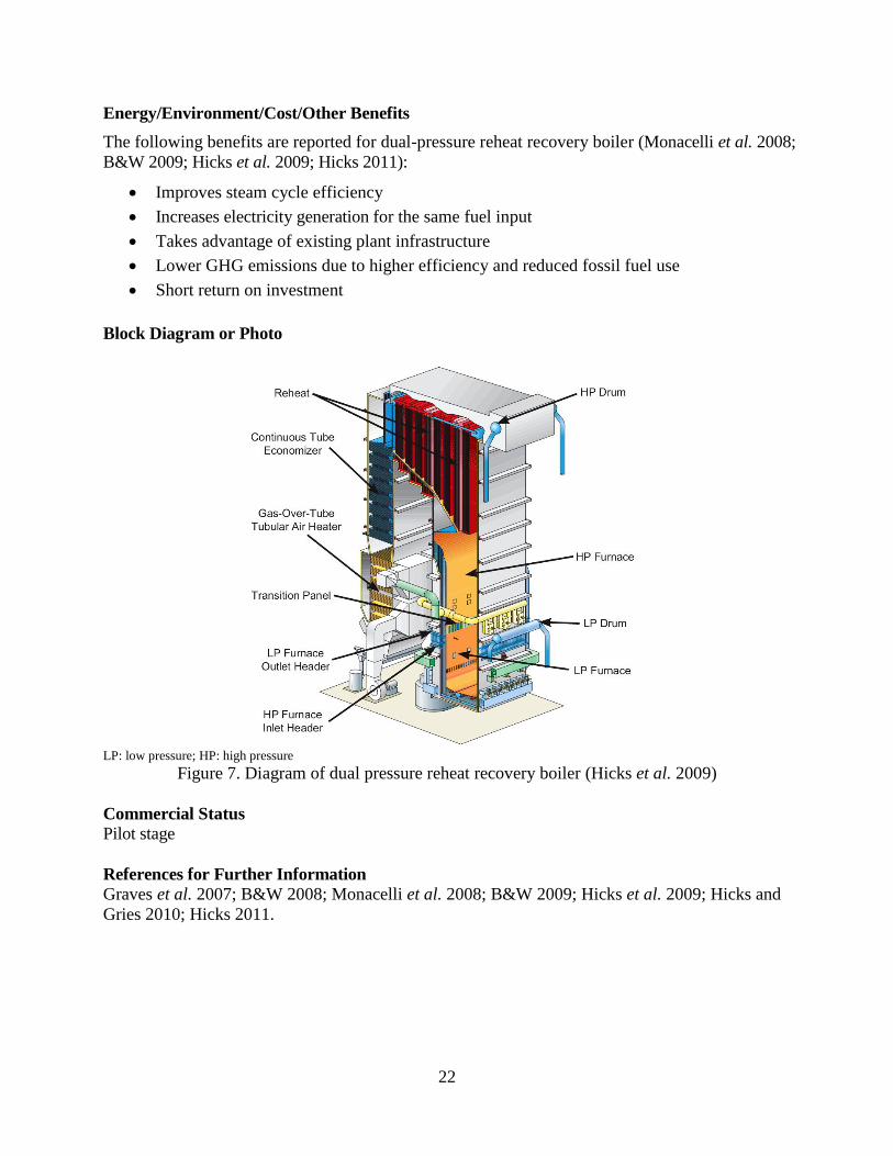
Energy/Environment/Cost/Other Benefits
The following benefits are reported for dual-pressure reheat recovery boiler (Monacelli et al. 2008;
B&W 2009; Hicks et al. 2009; Hicks 2011):
Improves steam cycle efficiency
Increases electricity generation for the same fuel input
Takes advantage of existing plant infrastructure
Lower GHG emissions due to higher efficiency and reduced fossil fuel use
Short return on investment
Block Diagram or Photo
LP: low pressure; HP: high pressure
Figure 7. Diagram of dual pressure reheat recovery boiler (Hicks et al. 2009)
Commercial Status
Pilot stage
References for Further Information
Graves et al. 2007; B&W 2008; Monacelli et al. 2008; B&W 2009; Hicks et al. 2009; Hicks and
Gries 2010; Hicks 2011.
Page 33
23
3.2.4. Borate Auto-causticizing
Description
The main function of the re-causticizing plant in a pulp mill is to regenerate the caustic. Caustic is
typically recovered from the spent pulping chemical in two stages: first, Na2CO3 is formed by the
combustion of black liquor in the recovery boiler, and then caustic is formed by the addition of
CaO to Na2CO3 in the re-causticizing plant. Lime is then recovered in the lime cycle through the
calcination of lime mud. Auto-causticizing could be an attractive alternative for kraft mills
because it allows higher caustic production without increasing lime demand and can even
eliminate lime demand (Kochesfahani and Bair 2002).
Borate auto-causticizing technology uses Neobor, a form of sodium borate (Na2B4O7·5H2O) to
replace lime. Each tonne of Neobor added to the pulping process replaces 10 to 30 times its
weight in lime (RTM 2010). The principal auto-causticizing reaction that occurs in the recovery
boiler is between sodium metaborate (NaBO2) and Na2CO3 in the molten smelt, which forms tri-
sodium borate (Na3BO3) (Reaction 1). The Na3BO3 reacts with the water in the smelt dissolving
tank to form sodium hydroxide (NaOH) and regenerate NaBO2 (Reaction 2) (Bjork et al. 2005).
- Auto-causticizing in the recovery boiler:
Na2CO3 + NaBO2 → Na3BO3 + CO2 (Reaction 1)
- Hydrolysis in smelt dissolving tank:
Na3BO3 + H2O → NaBO2+ 2NaOH (Reaction 2)
NaBO2 stays in solution and circulates through the chemical recovery cycle to continue forming
caustic in the recovery boiler. The borate compounds remain in the liquor cycle, self-regenerating
to be used again in producing caustic. NaBO2 drives auto-causticizing reactions in the recovery
boiler and forms NaOH in the smelt dissolving tank without the use of lime or additional
recovery processes, so this technology reduces energy consumption and increases causticizing
and calcining capacities. For kraft and soda pulp mills, reducing the lime kiln load not only
translates to lower operating costs, energy consumption, and emissions, but also significantly
reduces the amount of lime mud that requires special handling and disposal (ITP 2011c).
The concept of borate auto-causticizing was first investigated during the early 1980s in Europe;
however, after technical difficulties in only one mill trial, it was not pursued. Rio Tinto Minerals,
with support from the U.S. DOE, developed partial borate auto-causticizing, which is being
implemented in pulp mills worldwide to supplement conventional lime causticizing with almost no
capital investment (ITP 2011c).
A trial of partial auto-causticizing with sodium borate was first conducted at Georgia-Pacific Camas
mill WA (U.S.) from 1999 to 2000 for a period of more than16 months (Hunter et al. 2001). In
Europe, a full-scale partial borate auto-causticizing trial has been under way since November 2002
at the Stora Enso Norrsundet mill in Sweden (Bjork et al. 2005). In this trial, the total lime
requirement has been reduced by about 7 percent, and the auto-causticizing level has typically been
9 to 11 percent during the 15-month period. There is some indication that borates may enhance pulp
yield as well (Bjork et al. 2005). Partial auto-causticizing in the P.H. Gladfelter Co. mill in Spring
Grove PA (U.S.) increased production by roughly 5 percent in 2007 (ITP 2011c). However, the full
Page 34
24
borate auto-causticizing, which uses borates to drive all the causticizing reactions instead of just
lime causticizing and may cause corrosion in the recovery boiler, is still undergoing further research
and testing (ITP 2006c).
Energy/Environment/Cost/Other Benefits
The following benefits have been identified for borate auto-causticizing (RTM 2010):
Increases energy efficiency in chemical recovery process
Reduces lime demand, which reduces fossil fuel use in traditional lime kiln
Decreases fresh lime usage and limestone purchase
Reduces lime mud disposal costs
Reduces CO2 emissions from fuel burning and from calcining process in lime kiln
Increases causticizing capacity and pulp production without major investments
Decreases lime kiln operation and maintenance costs
Block Diagram or Photo
Recovery boilerDissolving tank
+H2O
Digester
CO2
Na2BO3
NaBO2+
2NaOH“Borated”
black liquor (mainly NaBO2)
Figure 8. Borate auto-causticizing process (ITP 2011c)
Commercial Status
Partial auto-causticizing: Semi-commercial stage
Full auto-causticizing: Development stage
References for further information Hunter et al. 2001; Kochesfahani and Bair 2002; Bjork et al. 2005; ITP 2006c; RTM 2010; ITP
2011c.
Page 35
25
3.2.5. Steam Cycle Washing
Description
Pulp washing is the most common unit operation in the pulping and bleaching process. The
general purpose of pulp washing is to maximize recovery from the pulp of inorganic pulping
chemicals and dissolved organic substances that can be used for fuel while minimizing the use of
fresh water and producing a clean pulp without spills into environment (Gullichsen 2000).
Efficient washing is critical to maximize return of pulping liquor to chemical recovery and to
minimize the cost of steam evaporation as well as to minimize washing loss into the bleach plant
because excess pulping liquor will increase consumption of bleaching chemicals (Bajpai 2010).
In addition, if not recovered by washing, the dissolved organic compounds (lignin and
hemicellulose) contained in the liquor will react with bleaching chemicals and thus increase
bleach chemical consumption.
Various washing technologies have been developed during the past 50 years, including drum
washing, diffusion washing, press washing, displacement washing, belt washing, and
dilution/extraction washing (Bajpai 2010). Rotary drum washing is the most common washing
technology used in pulp mills today with a dilution factor8 of 3 to 4 tonnes water per tonne of
oven-dry pulp. The amount of wash water required is about 12 to 13 tonnes/tonne oven-dry pulp
(Muehlethaler et al. 2008). However, there still exists a large potential for improving the washing
efficiency. The steam cycle washing technology was developed for this purpose.
The steam cycle washer is designed to dewater and wash wood pulp using counter current
washing, steam, and high-differential pressure. The entire process takes place within a pressure
vessel at 8 bar operating pressure. Within the pressure vessel is a Fourdrinier type dewatering
mechanism (Muehlethaler et al. 2008). The washing consistency9 of the developed steam-cycle
washer is 28 to 32 percent (fiber concentration about 280 to 320 kg/m3), and the dilution factor is
only 0 to 0.5 tonnes of water per tonne of oven-dry pulp. The amount of wash water required is
between 2.5 and 3 tonnes/tonne oven-dry pulp, compared to 12 to 13 tonnes/tonne oven-dry pulp
with the most common rotary drum washing technology, i.e., a reduction of 70 to 75 percent
(Muehlethaler et al. 2008). This technology uses less water compared to conventional washers
because it allows the pulp mat to be washed at a high consistency (ITP 2006f). As a result, less
energy is required for pumping and heating in the thickening, screening, and evaporation
operations. A pilot demonstration conducted at the Port Townsend Paper Mill (WA, U.S.)
achieved a 40-percent overall reduction in fuel or steam consumption for unbleached pulp
production (Muehlethaler et al. 2008).
The Idaho National Laboratory is collaborating with Steam Filter LLC in the design, fabrication,
and installation of a 450 to 500 Adt per day steam cycle washing machine for unbleached pulp.
The feasibility of this process has been tested and demonstrated through bench-scale and pilot
tests as of 2008 (DOE 2008). Given that current U.S. pulp washing equipment has an average age
of 45 years (ITP 2006f), significant energy saving opportunities exist with the commercialization
8 The dilution factor is the actual quantity of water used in pulp washing compared with the theoretical amount
required to displace the liquor from the thickened pulp. 9 The washing consistency means the fiber concentration in the pulp slurry during washing process, to some extent, it
reflects how much water be used indirectly. A lower washing consistency represents higher water consumption.
Page 36
26
of more efficient steam cycle pulp washing technology. However, this undergoing project was
discontinued by DOE due to unavailability of funding (Sastri Sept. 2012).
Energy/Environment/Cost/Other Benefits
The following benefits are reported for steam cycle washing technology compared to
conventional washers (DOE 2008; Muehlethaler et al. 2008):
Reduces fuel/steam consumption 40 percent overall
Reduces evaporative load 50 percent
Reduces plant effluent and freshwater usage 45 percent
Increases fiber yield 1 to 2 percent
Improves pulp quality
Reduces bleaching chemical consumption
Can reduce operational costs by $40 to $60/Adt pulp
Block Diagram or Photo
Figure 9. A steam cycle washer (Muehlethaler et al. 2008)
Commercial Status
Demonstration stage
References for Further Information Gullichsen 2000; ITP 2006f; DOE 2008; Muehlethaler et al. 2008; Bajpai 2010.
Page 37
27
3.2.6. Recycled Paper Fractionation
Description
Although recycled paper fractionation is not a new concept, only a small number of recycled
paper mills use this technology in deinking process. The purpose of fractionation is to improve
the quality of deinked pulp (DIP) by separating long fibers from short fibers and fines, according
to defined criteria such as size or deformability.
Fractionation can be done both in pressure-screens and in centrifugal cleaners. Fractionation
during recycled paper pulping can removes the detached ink particles from the vicinity of fibers
and thus prevents their excessive redeposition into the fibers. The ink particles need to be
removed once they are released to minimize the concentration of ink that remains after pulping.
This may require that the detached ink particles be removed from the pulp before defibration is
completed. Removing detached ink particles with multiple repeated pulping and fractionation
stages reduces the amount of attached ink to significantly lower levels than are possible with a
conventional pulping arrangement (Kemppainen et al. 2010).
The energy requirement for recycled paper fractionation is lower than conventional multi-stage
flotation deinking system. However, when fractionation is used, additional bleaching chemicals
might be required to compensate for the reduced flotation capacity. Andritz in Austria has tested
the potential of using recycled paper fractionation in a deinking line. The fractionation deinking
line has a 13- to 22-percent lower capital cost compared to traditional DIP lines. Using
fractionation can reduce electricity use by 11 to 13 percent and thermal energy use by 40 percent
(Hertl 2008). The technology is also being implemented and tested at Pearl Paper Mill in
Switzerland (Kramer et al. 2009).
Energy/Environment/Cost/Other Benefits
The following benefits are reported for deinking with recycled paper fractionation, compared to
that without fractionation (ECOTARGET 2009; Kemppainen et al. 2011; Korkko et al. 2011):
Decreases energy consumption
Improves efficiency of ink detachment
Reduces redeposition of ink on fibers
Reduces virgin fiber consumption
Increases DIP production
Improves pulp quality
Page 38
28
Block Diagram or Photo
Figure 10. Single-loop fractional deinking
(Standard 2-loops [left]; new single-loop deinking with recycled paper fractionation [right])
(ECOTARGET 2009)
Commercial Status
Demonstration stage
References for Further Information
Hertl 2008; ECOTARGET 2009; Kramer et al. 2009; Kemppainen et al. 2010; Kemppainen et al.
2011; Korkko et al. 2011.
3.2.7. New Flotation Deinking
Waste paper is an important raw material for the pulp and paper industry. The recovery and
utilization rate of waste paper has been increasing during the past decade due to the developments
of deinking technology. Deinking (e.g., flotation, washing, or centrifugal cleaning) is the
industrial process of removing printing ink from fibers of recycled paper (Vashisth et al. 2011).
Flotation deinking is the predominant technology worldwide because of its advantages with
regard to selectivity, yield, water management and reject handling (Kemper 1999). The term
flotation is the generalization of processes in which the main stage is the bubble-particle adhesion
(or attachment), which is controlled by surface chemistry and by the hydrodynamic and
operational parameters of the flotation cell (Costa and Rubio 2005).
Flotation deinking processes were originally developed based on the experience obtained from
mineral flotation process and have not been fully optimized for paper deinking. In contrast to the
mineral flotation, the accept in flotation deinking is not the foam but the remaining suspension.
The detached ink particles are accumulated in the foam by means of the introduced air (Kemper
1999). In addition, flotation deinking is a relatively young process compared to mineral flotation
and it is still not effective to remove the tiny ink particles and only limited process control
mechanisms are available (Deng and Zhu 2004; ITP 2007d). The following subsections describe
four new flotation deinking processes or equipments.
Page 39
29
3.2.7.1. OptiCell FlotationTM
Description
OptiCell FlotationTM
by Metso is based on computational fluid dynamics and uses new image
analysis methods. It is designed to provide smooth flow velocities that allow unobstructed
transfer of bubbles to the surface of the pulp mixture or froth, which enhances the efficiency of
ink removal. The heart of OptiCell FlotationTM
is the aeration injector, which ensures optimal
bubble size distribution. The injector is designed based on the experiences gained with earlier
flotation technologies combined with modern computational fluid dynamics calculations and new
image analysis methods.
The linear structure of the flotation cells has a large surface area, which has reject separation and
fiber loss. This flotation cell design also contributes to high sludge consistency (less water in the
sludge) by ensuring smooth drainage of froth (Aksela 2008). The elliptical shape of the flotation
cells in this technology is optimal for internal pulp circulation for improved ink removal.
Moreover, the flatness of the cells intensifies the rise of air bubbles within the available volume.
The first OptiCell flotation system started operation in September, 2008 at Stora Enso’s Maxau
mill in Germany which has approximately 1,000 tpd deinking facility (Metso 2012b).
Energy/Environment/Cost/Other Benefits
Metso claims the following benefits for OptiCell FlotationTM
compared to conventional systems
(Aksela 2008; Metso 2012b):
Low energy consumption
Improves flotation capacity
Removes ink effectively
Reduces fiber loss
Improves pulp brightness
Reduces operation costs
Reduces space requirements
Block Diagram or Photo
Figure 11. OptiCell flotation
TM cell (Metso 2012b)
Commercial Status
Semi-commercial
References for Further Information Aksela 2008; Metso 2012b.
Page 40
30
3. 2.7.2. Deaeration Foam Pump 4000TM
Description
The Deaeration Foam Pump (DFP) 4000TM
, developed by Voith, is a compact unit that integrates
several elements of the flotation deinking system. Combining the pump and deaeration machine
into one unit, the deaeration foam pump replaces the foam destroyer, foam tank, stirring unit, and
pump and costs less than the current suite of equipment.
The DFP 4000 has two parts: in the upper part, foam is pre-deaerated by a mechanical foam
destroyer; in the lower part, centrifugal force generated by a quick rotational movement further
deaerates the foam. The resulting low-air-content suspension is brought to the required pressure
so that it can be conveyed out of the machine to the next process stage. The air released during
deaeration is conveyed out of the machine through a special air chamber on the side so that the
airflow does not obstruct the foam entering from above (Dreyer 2010).
The new pump can be linked directly to the deinking machine, forming a clean and closed
disposal system. Because the deaeration pump can be placed at the same level as the flotation
cells, the entire system requires less space than previous systems, so a cellar (or additional floor
height) is no longer needed to accommodate the system. When the foam mass passes through the
DFP 4000, the foam’s air content is reduced from 80 percent to an average of 8 percent (Voith
2011a). Conventional deaeration systems reduce the air content to approximately 12 percent. The
first DFP 4000 operating in a paper mill has been in service since September 2009 (Dreyer 2010).
Energy/Environment/Cost/Other Benefits
Voith claims the following benefits for the DFP 4000TM
compared to conventional systems
(Dreyer 2010; Voith 2011a):
Eliminates foam tanks used in conventional deinking flotation
Reduces total investment
Reduces air requirement in flotation
Improves foam deaeration
Has stable operation even with fluctuations in foam action and quantity
Reduces operating costs
Reduces space requirement
Page 41
31
Block Diagram or Photo
Figure 12. Deaeration Foam Pump 4000
TM (Voith 2011a)
Commercial Status
Semi-commercial
References for Further Information
Dreyer 2010; Voith 2011a.
3. 2.7.3. Low Energy FlotationTM
Description
Flotation deinking system integrated with Low Energy FlotationTM
(LEF) is another new
technology developed by Voith for removing inks and other contaminants from recovered paper.
LEF is designed with a two-stage (primary and secondary) system to ensure maximum elimination
of hydrophobic components with maximum DIP yield. The specific energy consumption for this
new flotation technology is 10 to 15 kWh/t (Voith 2011b).
The LEF unit consists of several flotation cells. The diffusers, which are self-operating aeration
elements that draw air in, are the core of each flotation. The diffusers draw in the air they need to
remove the particles of printing ink. The aeration elements are structured in such a way that they
cause a whirl that reduces the size of the air bubbles while creating a uniform mixture. The small
water-repellent particles of printing ink attach themselves to the air bubbles. When the turbulence
calms, the smaller air bubbles combine to create larger ones. Small particles of ink continue to
adhere to the bubbles while larger particles become attached to them. In this way, the size of the
air bubbles adapts optimally to the size of the ink particles (PearlPaper 2010).
LEF is applied in all graphic and tissue grades of recovered paper. It has self-regulating control
with reject flow control, high operational reliability, and a wide production range due to
interconnecting cells. The first LEF system with a production of 800 tpd is already running
successfully. To date, more than 15 systems have been installed worldwide (Voith 2011b).
Page 42
32
Energy/Environment/Cost/Other Benefits
Voith claims the following benefits for the LEF system compared to conventional systems
(PearlPaper 2010; Voith 2011b):
Reduces flotation energy use by approximately 33 percent
Increases air (60 percent) available for flotation
Increases DIP capacity
Minimizes fiber loss
Separates inks over a broader particle range (approximately 5 to 500 micrometers)
Reduces space requirement
Block Diagram or Photo
Figure 13. Low Energy Flotation Cell structure (Voith 2011b)
Commercial Status
Semi-commercial
References for Further Information
PearlPaper 2010; Voith 2011b.
3. 2.7.4. Mac Flotation Cell
Description
The Mac flotation cell developed by Kadant-Lamort Inc. is another innovation that could save
energy compared to conventional flotation systems. It integrates small new auto-clean low-
pressure injectors with a flotation cell. The injectors aerate the stock before it is pumped and sent
tangentially to the top of the cell. In the cell, air bubbles collect ink particles and rise up to the top
to create a thick foam mat that is evacuated because of the slight pressurization of the cell. The
partially de-inked stock then goes to a de-aeration chamber and is pumped to the next stage. In the
second stage, the operation is exactly the same as for the first stage, with the same number of
Page 43
33
injectors and same flow (Kadant 2011). This operation is repeated up to five times for a high ink
removal rate. Re-mixing of the air coming from downstream stages of the process aids the upstream
stages, improving overall cell efficiency. Adjustable and selective losses of fiber depend on the
application and technical requirements (inks, or inks and fillers). The use of low-pressure injectors
in the Mac flotation cell could save 25 to 30 percent of the energy used in conventional flotation
systems (ECOTARGET 2009).
Energy/Environment/Cost/Other Benefits
Kadant-Lamort Inc. claims the following benefits for the Mac flotation cell compared to
conventional cells (ECOTARGET 2009; Kadant 2011):
Reduces energy consumption by 25 to 30 percent
Has low specific power consumption
Has high rate of ink and hydrophobic particle removal
Improves flotation efficiency
Reduces fiber loss
Eliminates second-stage cell
Reduces space requirement
Block Diagram or Photo
Figure 14. Mac flotation cell with low-pressure injectors (ECOTARGET 2009)
Commercial Status
Demonstration stage
References for Further Information
ECOTARGET 2009; Kadant 2011.
Page 44
34
3.2.8. Surfactant Spray Deinking
Description
Surfactant spray is a new technology for recycling various grades of paper that improves ink
removal, reduces the use of chemicals and the loss of fiber and water during deinking, and
provides better process control than current deinking technologies (Zhao et al. 2004). The
surfactant increases ink removal by adsorbing onto the surfaces of the ink particles and reducing
their hydrophobic characteristics, so they can more readily be separated and removed from the
pulp suspension. Use of surfactants also improves process control by preventing dilution of the
foaming agent in the bulk volume of the pulp mixture. Because surfactant spray significantly
improves the deinking process, reduces the use of chemicals and the loss of fiber and water, it
reduces operating costs.
Surfactant spray deinking uses an atomizer to spray foam at the top of the flotation cell. The
foaming agent generates stable foam for ink removal, a collector is applied to agglomerate small
ink particles for removal, and a dispersant is used to prevent ink particles from re-depositing onto
fiber surfaces (Zhao et al. 2004). The concentration and distribution of various surfactants is
controlled during the surfactant spray deinking process (Deng and Zhu 2004).
Surfactant spray technology has been demonstrated in both laboratory- and pilot-scale flotation
deinking trials at IPST in the U.S. and in Voith-Sulzer’s commercial flotation cells for deinking
old newsprint, old magazines, and old corrugated container board (Deng and Zhu 2004; Delozier
et al. 2005). The brightness of the DIP produced using surfactant spray deinking was slightly
lower that DIP from conventional deinking but was considered acceptable in view of the
significantly increased yields (Delozier et al. 2005). This technology was successfully
implemented in a single flotation unit within the deinking line of a mill producing newsprint from
100-percent secondary fiber, with a more than 50-percent reduction in fiber loss from the unit
without negatively affecting final pulp quality (Delozier et al. 2005). Single-cell commercial runs
(450 tpd DIP) using surfactant spray in a flotation deinking line showed a 3.5-percent increase in
yield, 380 liters per minute savings in water use, and 10-percent chemical savings (Deng and Zhu
2004).
Surfactant spray technology can be easily retrofitted into an existing system without significant
modifications and capital cost. The estimated capital investment is approximately $10,000 for one
flotation cell (Deng and Zhu 2004).
Energy/Environment/Cost/Other Benefits
The following benefits are reported for the surfactant spray technology compared to conventional
flotation deinking (Deng and Zhu 2004; Delozier et al. 2005; ITP 2007d):
Reduces fiber loss up to 50 percent
Increases DIP yield (IPST demonstrated a 3.5-percent yield increase)
Improves deinking efficiency
Reduces water and deinking chemical use (380 liters per minute of water savings and 10
percent of chemical savings were realized in IPST)
Reduces formation of stickies
Page 45
35
Improves paper quality
Requires low capital expenditure and minimal equipment modification
Block Diagram or Photo
Figure 15. Surfactant spray deinking in a mill trial (Deng and Zhu 2004)
Commercial Status
Demonstration stage
References for Further Information
Deng and Zhu 2004; Zhao et al. 2004; Delozier et al. 2005; ITP 2007d.
3.2.9. Pulsed Power Technology for Decontamination of Recycled Paper
Description
Contaminants in recycled paper can degrade the properties of the final products and can also lead
to substantial downtime in the recycled paper mill. A category of contaminants known as
“stickies,” which includes pressure-sensitive adhesives and hot melts, is especially troublesome.
Stickies are usually controlled during the recycling process by screening and cleaning equipment
or chemical additives such as minerals and polymers (Banerjee 2005). However, these controls
are not 100-percent effective, so many stickies remain on DIP and negatively affect the remainder
of the pulping process. Pulsed power technology is a new decontamination method based on the
principle of electro-hydraulic discharge. It can effectively remove stickies from recycled paper
pulp and can replace the costly minerals and polymers used in conventional control of sticky
contaminants (OIT 2002; ITP 2007c).
Pulsed power technology diffuses stickies with a shock wave from a spark discharging
underwater and then oxidizes them using hydroxyl radicals created from the water. Oxidation
causes the stickies to lose their tack and become benign, thus allowing recycling to continue
unimpeded (ITP 2007c). Experiments carried out by IPST have shown that discharging a 3 kilovolt
Page 46
36
(kV) and 50 kiloampere (kA) underwater spark over a period of 50 to 100 milliseconds can diffuse
and oxidize the stickies in recycled paper pulping process (OIT 2002).
Full-scale trials of pulsed- power technology have been conducted at several papers mills in the
U.S.: Appleton paper mill in West Carrollton OH, Graphics Packaging mill in Kalamazoo MI,
Stora Enso mills in Duluth MN and Wisconsin Rapids WI (owned by NewPage now), and the
Jackson Paper mill in Sylva NC. In these trials, the sparker not only detackified stickies effectively
but also increased the efficiency of their removal by centrifugal cleaners, improved the
effectiveness of the flotation systems, and increased the efficiency of flotation deinking (Banerjee
2005). It is estimated that the sparker improves the efficiency of hydrocyclone cleaners, deinking
cells, and dissolved and dispersed air flotation units by 10 to 15 percent (Banerjee 2005).
Energy/Environment/Cost/Other Benefits
The following benefits are reported for the pulsed power technology compared to conventional
methods for decontamination in recycled paper mill (OIT 2002; Banerjee 2005; ITP 2007c):
Reduces energy use by 10 to 15 percent
Increases brightness
Reduces need for bleaching and agglomeration chemicals
Reduces down time
Improves product quality
Has low installation cost
Reduces operational costs
Block Diagram or Photo
Not Available
Commercial Status
Demonstration stage
References for Further Information
OIT 2002; Banerjee 2005; ITP 2007c.
Page 47
37
3.3. Emerging Papermaking Technologies
The subsections below describe the following six emerging technologies that save energy and/or
reduce GHG emissions in the papermaking process: Aq-vane technology, high consistency
papermaking, dry sheet forming, displacement pressing, new fibrous fillers, and laser ultrasonic
stiffness sensor.
3.3.1. Aq-vane Technology
Description Stratified forming is used to produce multi-layer paper and paperboard. Instead of being made
from a single paper web that forms a sheet containing mixed or uniform materials throughout,
conventional linerboard consists of several distinct layers composed of different raw materials
that are formed with different headboxes. Stratified forming technology was developed to
produce multi-layer paper and paperboard using only a single headbox, which reduces complexity
as well as energy and raw materials consumption (Soderberg 2006).
However, in a stratified forming set-up, the pulp streams are separated by vanes or lamellas
which form a wake in which uncontrolled mixing can take place, which degrades the purity of the
layers formed using this technology (Soderberg 2009). A new type of stratified technology, Aq-
vane, was developed by STFI-Packforsk to overcome this problem (Soderberg 2006). This
technology entails injecting a thin passive liquid layer (a liquid vane or Aq-vane) in the headbox
through a narrow hollow channel between neighboring pulp streams, which prevents mixing
between the layers (Soderberg 2008).
Trials of Aq-vane technology on three types of paper produced by the EuroFEX pilot paper
machine showed that, with this technology, the filler content in papermaking can be increased to
45 percent from the previous 35, and energy consumption was reduced by 16 percent
(ECOTARGET 2009). Another feature of the Aq-vane technology is that the layer purity and
separation can be controlled externally by tuning a set of process parameters. This creates the
possibility of widespread industrial application of stratified forming, improved product quality,
and the possible development of new paper grades. The new stratified forming technology can be
applied to paper grades of almost any grammage (Soderberg 2009).
Energy/Environment/Cost/Other Benefits
STFI-Packforsk claims the following benefits for the Aq-vane technology compared to
conventional stratified forming technology (Soderberg 2008; ECOTARGET 2009):
Reduces fibrous raw material use
Reduces energy consumption due to less fiber raw materials usage
Improves paper properties with higher layer purity
Improves web surface roughness and bending stiffness
Reduces operation costs
Page 48
38
Block Diagram or Photo
Figure 16. Comparison of conventional and new stratified forming technology (Soderberg 2006)
Commercial Status
Development stage
References for Further Information
Soderberg 2006, 2008; ECOTARGET 2009; Soderberg 2009.
3.3.2. High Consistency Papermaking
Description
In the current papermaking process, the Fourdrinier and twin-wire formers are widely applied for
thin paper and multilayered paper or paperboard in papermaking. However, both Fourdrinier and
twin-wire formers use low consistency forming technology, which means the paper is formed in a
range of 0.5-1.0 percent low consistency of stock (5-10 g fibers per kg water). The high levels of
dilution (due to low slurry consistency) make the short circulation of modem paper machines large
and energy intensive (Cichoracki et al. 2001). In the low consistency forming process, chemicals
have to be employed to increase the retention of furnishing components on paper web. In addition,
the recovery of un-retained material and water requires several units of equipment and operation,
which consumes high amount of energy (EC 2012).
The high consistency papermaking process would require that the approach and short circulation
systems, fluidization and dewatering processes take place at high consistency (EC 2012). In high
consistency forming, the processed pulp enters at the forming section, and has more than double the
consistency (3 percent) compared to that of normal slurry. High consistency papermaking could
increase forming speed and leads to energy savings in the pressing section, due to reduced
dewatering and vacuum power requirements (Martin et al. 2000b). Increasing the forming
consistency from 0.7-percent to 7-percent would reduce the flows around the wet end by 10 fold.
Page 49
39
Since 25 percent of a paper machine’s energy consumption is used for pumping water and stock
alone, significant energy savings could be realized (Cichoracki et al. 2001).
Efforts aimed at increasing the forming consistency have been going on since 1980s, but with little
success (EC 2012). This development has been limited to a consistency of around 3 percent due to
the deterioration in sheet properties. Recently, it has been suggested that up to 6% may be possible
while still achieving good formation (Cichoracki et al. 2001). A high consistency device was built
by Cichoracki et al. (2001) for forming webs at high consistency (5-15 percent). To date, webs have
been formed at 5-12 percent consistency, with grammages ranging from 275 to 1000 g/m2. The web
width is 300 mm and speeds up to 700 m/min are currently possible. However, a current drawback,
which still needs to be overcome, is the defiberability of the sheet as compared to that of
conventional market pulp sheets. Also, the modern paper machines have winder web width and
higher machine speed than can be achieved with the current technology mentioned above.
It is expected that high consistency short circulation process will consume 50 percent less energy
and 30 percent less vacuum energy (EC 2012). Due to improved fibers retention, the consumption
of chemicals and the environmental load of the process will also be reduced. Results from early
high consistency research indicate that in addition to economic and environmental benefits other
advantages may be gained in terms of sheet properties and process variables. Stock storage and
pump size could be reduced, and initial dewatering elements in the forming section could be
eliminated, all resulting in simplified wet end section of papermaking and a shorter less expensive
paper machine (Cichoracki et al. 2001; EC 2012). It was reported that 10-15 percent savings in
capital costs can be realized for the paper machine wet-end since it allows for reductions of the size
of both the forming and drainage area (Martin et al. 2000b).
The technology can be installed as an add-on technology to existing processes with some
modifications (Martin et al. 2000b). Currently, the fundamental problem of high consistency
forming is the lack of control of fiber orientation (Johansson 2001). A breakthrough in high
consistency papermaking would require new technology where current unit operations, i.e. head-
box, drainage and pressing are integrated together in a compact way (EC 2012). Progress is needed
in the mixing of fibers and chemicals and in screening, air removal, fluidization, dewatering of
furnish, and in process control (EC 2012).
Energy/Environment/Cost/Other Benefits
The following benefits are reported for high consistency papermaking (Martin et al. 2000a; Martin
et al. 2000b; Cichoracki et al. 2001; EC 2012):
Reduces energy use in stock preparation, vacuum system, and dewatering
Electricity savings are estimated at 8 percent
Reduces water consumption in papermaking
Saving fiber use by 5-8 percent
Reduces chemical additives
Simplifies wet end process of papermaking
Improves product quality
Reduction of 10-15 percent in capital costs for the wet end of the machine
Page 50
40
High consistency formers are expected to cost $70/t paper with an additional maintenance
cost of $0.72/t paper
Block Diagram or Photo
Not available
Commercial Status
Pilot stage
References for Further Information
Martin et al. 2000a; Martin et al. 2000b; Cichoracki et al. 2001; Johansson 2001; EC 2012.
3.3.3. Dry Sheet Forming
Description
With current papermaking technology, a large amount of water has to be added during the stock
preparation process to dilute the fibers to a specified concentration. The water in the pulp then has
to be removed in the paper machine with different dewatering equipments in the following
forming, pressing, and drying process. The majority of the energy consumed in papermaking is
used for dewatering. The dryer section, in particular, uses about 67 percent of total energy use in
papermaking (Chudnovsky et al. 2004). If the papermaking process could use less water or no
water, a large amount of energy that is now used for paper drying could be saved.
The principle behind dry sheet forming is the production of paper without adding water (de Beer
et al. 1998). It relies on high levels of turbulence in the air stream to produce paper products.
Fibers can be dispersed either mechanically or using “air laying” techniques. In air laying, the
fibers are suspended in the air, and the paper is formed in this suspension. Resins are sprayed on
the sheet and are then polymerized to help form the web (de Beer et al. 1998). The air laying
technology permits a higher production rate and better control of air streams compared to other
dry sheet forming processes, so most dry sheet forming processes are using this technology. A
typical dry sheet forming line consists of four units: fiber preparation, web formation, web
consolidation, and finishing (Jiang 1997).
Air-laid dry sheet forming technology was first commercialized during the early 1980s by
Moeller and Jochumsen, a Danish firm. The worldwide installed capacity of this technology is
about 350,000 t/year and growing rapidly (Xu et al. 2010). New capacity additions of 120,000
t/year are expected during the next few years, mostly in North America (Xu et al. 2010). It
estimated that 50 percent of drying energy consumption could be eliminated with 150 to 250
kWh/t paper of additional electricity consumption to maintain the air stream and motor drive for
the equipment using air-laid dry sheet forming technology (Martin et al. 2000b; Xu et al. 2010).
Because no water is used in this technology, it avoids the wastewater effluent and treatment that
are part of conventional paper mill operations.
The disadvantages of dry sheet technology include increase electricity use in paper forming, less
uniform paper thickness, lower sheet strength, and reduced smoothness. However, the paper
Page 51
41
produced with dry sheet technology tends to be softer than that produced by conventional
technology. As a result, dry sheet forming technology is often used to produce personal care
products (diapers, feminine hygiene and adult incontinence products, etc.) and some specialty
products (tableware, medical products, hot towels, etc.) (Martin et al. 2000b). Another barrier
facing the dry sheet forming is its lower speed for producing the standard paper grades compared
to the conventional technology.
If this technology were commercialized to manufacture standard paper grades, direct investment
costs could be 30 to 50 percent of those for a conventional non-integrated paper mill. In addition,
O&M costs are expected to be lower (Jiang 1997; de Beer et al. 1998). The current installed dry
sheet technology capacity in North America is estimated to be only 0.1 percent of total paper
production (Xu et al. 2010). The market potential in the U.S. for the production of specialty
products is estimated to be 5 percent of total U.S. paper production (Xu et al. 2010). The
technology has not yet been used for producing other types of paper products although it has been
demonstrated that producing corrugated medium and molding board with dry sheet forming is
possible. It appears that dry sheet forming technology will continue to be developed for specialty
applications and is not likely to be adapted in the near future for production of standard paper
grades (Martin et al. 2000b; Xu et al. 2010).
Energy/Environment/Cost/Other Benefits
The following benefits are reported for dry sheet forming technology compared to conventional
technology (Jiang 1997; de Beer et al. 1998; Martin et al. 2000b; Xu et al. 2010):
Reduces drying energy consumption by 50 percent
Eliminates wastewater effluent and treatment
Has investment costs 30 to 50 percent of those for a conventional non-integrated paper
mill
Has lower O&M costs compared to conventional technology
Produces softer paper products
Block Diagram or Photo
Figure 17. Diagram of a dry sheet forming process (Ng. and Grandmaison 1995)
Page 52
42
Commercial Status
Semi-commercial for production of specialty products (diapers, feminine hygiene and adult
incontinence products, etc.);
Development stage for producing standard paper grades
References for Further Information
Ng. and Grandmaison 1995; Jiang 1997; de Beer et al. 1998; Martin et al. 2000b; Chudnovsky et
al. 2004; Xu et al. 2010.
3.3.4. Displacement Pressing
Description
The dryer section accounts for about 78 percent of dewatering costs; of the rest, 12 percent are
attributable to the press section and 10 percent to the forming section (Ghosh 2009). Thus,
improving the dewatering performance before the dryer section is the most cost effective way to
reduce drying energy consumption.
The current pressing technology uses mechanical pressure to remove water from the wet web.
Although this method is effective, it produces a maximum solids content of 50 to 55 percent.
Solids content of 65 percent has been reported in laboratory studies, and the current theoretical
limit of paper press is 80-percent solids (Agenda2020 2010).
Displacement pressing technology is a new method for pressing the paper web that has been
developed at the laboratory scale to enhance the solids content of the web out of the press section.
This technology combines mechanical and air pressure, pressing web lightly while forcing air
through it and using special pressing fabrics with a special four-roll Beck cluster press (BCP).
BCP provides a pressurized atmosphere that acts on the moving web and fabric. The special
fabric designed for this process use this atmosphere to press the sheet and at the same time force
air through the sheet to carry out displacement pressing. The effective dewatering as a result of its
higher pressures and longer dwell times giving displacement pressing technology tremendous
high speed potential (Beck 2006).
A displacement pressing simulator was built by Voith Fabrics to develop and test pressing fabric
on a small scale. Voith Fabrics also designed and built a narrow laboratory-scale BCP that is 5
inches wide. This study also looked at the effect of displacement pressing on sheet properties and
found that this technology can produce a paper web with maximum paper solids content
exceeding 60 percent (Beck 2006). If this technology is successful, more than 30 percent of
drying energy consumption could be reduced. Based on the significant results of the small-scale
BCP trial, Voith Fabrics built a one-meter pilot BCP press stand to determine scalability of the
process.
Page 53
43
Energy/Environment/Cost/Other Benefits
Voith Fabrics Inc. claims the following benefits for displacement pressing technology compared
to conventional pressing technology (OIT 2001b; Beck 2006):
Reduces drying energy consumption
Increases web solids content before dryer
Improves paper strength properties
Reduces paper breaks
Reduces raw material costs
Block Diagram or Photo
Figure 18. Photo of displacement dewatering equipment (Beck 2006)
Commercial Status
Development stage
References for Further Information
OIT 2001b; Chudnovsky et al. 2004; Beck 2006; Ghosh 2009; Agenda2020 2010.
3.3.5. New Fibrous Fillers
Description
Mineral fillers are commonly used to replace wood fibers in the production of paper products and
to reduce production cost and energy consumption. The filler loading is limited to roughly 15 to
20 percent of a product because of paper strength and quality requirements (ITP 2006b). If
mineral filler exceeding those percentages was used in papermaking, it could degrade paper
properties. However, G.R. International Inc. (GRI), in cooperation with several major industrial
partners, has developed a new fibrous filler that may overcome these problems and achieve
additional replacement of high cost wood fibers.
Page 54
44
The fibrous fillers based on calcium and silica in some cases can displace more than 40 percent of
the pulp in papermaking while maintaining paper properties and reducing energy consumption
(ITP 2010). GRI and Lawrence Livermore National Laboratory (LLNL) demonstrated the
chemical reaction that forms the new filler, and the filler manufacturing process and its paper-
enhancing capabilities were optimized in a scaled-up pilot reactor (ITP 2006b). GRI has been
working with the University of Washington and Washington State University to optimize and
evaluate fibrous fillers and with various industrial partners, including Georgia-Pacific Camas and
E3 Energy Partners, to evaluate the performance of the technology in papermaking (ITP 2010).
Energy savings from using new fibrous fillers are attributable to avoided wood pulp production
and reduced drying energy due to an increase in the percentage of press solids in the sheet
(Mathur 2006). Reportedly, the use of this fibrous fillers could reduce energy consumption by 25
percent and costs by $10 to $50/t paper produced (ITP 2006b).
The new advanced fibrous filler can also be used to replace other expensive fillers, such as TiO2
and silica. Fibrous fillers will also lead to better retention of fibers, additives, and pulp fines,
resulting in significantly reduced COD and biological oxygen demand (BOD) in the mill process
water. Fibrous fillers could be used in all paper and paperboard products. Free sheet papers are
the most likely targets in the near term, but wood-containing papers and newsprint could
eventually use this product as well (ITP 2006b). GRI has a plan to expand the current prototype
plant to a full commercial plant, and the technology is available for licensing (ITP 2010).
Energy/Environment/Cost/Other Benefits
GRI claims the following benefits for fibrous filler technology compared to conventional
papermaking and/or filler technology (ITP 2006b):
Reduces energy use by 25 percent
Replaces expensive fillers, such as TiO2 and silica
Increases solid content of paper web
Improves retention/ Increases water drainage rate
Improves paper optical properties (brightness, opacity, printing quality)
Reduces BOD, COD, and turbidity in mill process water
Reduces costs by $10 to $50 per tonne paper manufactured
Creates additional revenue in new products
Block Diagram or Photo
Not Available
Commercial Status
Pilot stage
References for Further Information
ITP 2006b; Mathur 2006; ITP 2010.
Page 55
45
3.3.6. Laser Ultrasonic Stiffness Sensor
Description
Stiffness is one of the most important parameters for papermaking process and quality control.
The current measurement method is using offline samples that cut from the reel after the paper
has been already manufactured. The measurements are conducted manually, slowly, and cannot
provide feedback to adjust paper quality during manufacturing (ITP 2006e). If the sample doesn’t
meet specifications, the entire roll is sold as an inferior grade or remanufactured. To avoid this
costly outcome, manufacturers often over-engineer paper, using more pulp than necessary to
ensure the final product meet stiffness and other quality standards. This results in excess raw
materials and energy consumption (LBNL 2002). As much as 5 percent of the paper produced
each year is considered substandard and must be re-pulped and remanufactured to improve its
mechanical properties and strength (ITP 2007b). Large amounts of raw materials and energy used
for remanufacturing could be avoided if the web stiffness could be measured and controlled in
real time in papermaking process.
The velocity of ultrasound can be used to determine various mechanical properties of the paper. For
example, the square of ultrasonic velocity is proportional to paper stiffness (ITP 2007b).
Researchers at LBNL have developed a laser ultrasonic stiffness sensor that could measure paper's
bending stiffness and shear strength in real time, allowing manufacturers to optimize the amount of
raw materials used by running closer to specifications (LBNL 2005). Using this technology,
manufacturers could focus the manufacturing process on stiffness targets (rather than the current
practice of using basis weight targets) and adjust paper machines accordingly during production.
Real-time control of paper machines would enable more efficient use of materials, including a
higher percentage of recycled fibers (ITP 2006e).
The ultrasonic laser stiffness sensor has been tested successfully at three sites in the U.S.: Mead
Paper Company’s research center in Chillicothe OH, a paper mill in Boise ID, and a paper mill in
Jackson AL (LBNL 2005; ITP 2006c). The sensor was installed on a pilot paper-coating machine
and ran six paper grades, ranging from lightweight copy paper to heavy linerboard. The sensor’s
signals remained clear, even at paper speeds up to 1500 meters per minute (m/min), and the laser
did not damage the paper.
Implementation of this technology at the mill scale could result in an estimated 3 percent energy
savings: a 2-percent decrease in basis weight (because manufacturers would be able to run closer to
specifications rather than over-engineering their products), and a 1-percent reduction in off-grade
paper that must be recycled (which avoids the additional energy necessary to reprocess the recycled
fiber in the mill) (Kramer et al. 2009).
Energy/Environment/Cost/Other Benefits
The following benefits are reported for using laser ultrasonic stiffness sensor compared to
conventional methods (LBNL 2002; ITP 2006e; Kramer et al. 2009):
Reduces refining and re-pulping
Reduces energy consumption by about 3 percent at the plant level
Improves product quality and consistency
Increases use of recycled paper
Page 56
46
Reduces raw material use in papermaking
Reduces costs other than energy by reducing the production of below-specification paper
Minimizes waste, including lost fiber quality during drying and re-wetting
Block Diagram or Photo
Figure 19. Laser ultrasonic stiffness sensor working principle (LBNL 2002)
Commercial Status
Demonstration stage
References for Further Information
LBNL 2002, 2005; ITP 2006c, 2006e, 2007b; Kramer et al. 2009.
Page 57
47
3.4. Emerging Paper Drying Technologies
The papermaking process is essentially a massive dewatering process with drying as the most
significant element in terms of equipment investment or energy consumption. Currently, the most
common paper drying method uses steam as the main source of heat energy in a series of rotating
cylinders (about 1.5 to 2 meters [m] in diameter and each cylinder up to 10 m long) as the heat
transfer area. This method is used in 85 to 90 percent of installations in the paper industry
(Mujumdar 2006). Although the paper drying process removes only about 1 percent of the
original water, it consumes about 67 percent of the total energy required in papermaking,
equivalent to 25 to 30 percent of the total energy used in the pulp and paper industry (IEA 2009).
As mentioned previously, the paper drying process is the most expensive part of the paper
machine. Although retrofit measures such as spoiler bars and stationary siphons have been
developed and widely applied to conventional dryers for improving their energy efficiency and
drying rate, these dryers are still relatively inefficient and capital intensive. The emerging paper
drying technologies described in the subsections below increase both the energy efficiency and
productivity of conventional paper drying technology.
3.4.1. Gas-fired Dryer
Description
To improve the current paper drying efficiency, the Gas Technology Institute (GTI), with Boise
Paper Solutions, Groupe Laperrière and Verreault (GL&V) USA Inc., and Flynn Burner
Corporation in the U.S., developed a high efficiency gas-fired paper dryer based on the
combination of ribbon flame and advanced heat transfer enhancement technique. This gas-fired
cylinder dryer involves combusting natural gas and air in small dimples or cavities. The airflow
creates a vortex within each dimple, resulting in highly stable mini flames and uniform drum
surface temperatures (ITP 2006d). This is a high-efficiency alternative to traditional steam-heated
dryers and is expected to exceed the performance of existing paper drying systems.
This new gas-fired dryer was initially evaluated in GTI’s combustion laboratory and then
successfully tested at Western Michigan University’s pilot paper machine. The conventional
steam heated dryer at Western Michigan University consumed about 21 kW of saturated steam
heat to reach 120ºC on the drum surface compared to less than 14.7 kW of heat is necessary for
the gas-fired dryer to reach the same surface temperature. Moreover, about 260 ºC dryer surface
temperature was reached during linerboard production, which increased the drying rate by 4 to 5
times compared to the rate of existing steam-heated dryers (Chudnovsky et al. 2004). A full-scale
demonstration is being conducted on a linerboard paper machine at Liberty Paper Inc., an LDI
Company (ITP 2006c).
This gas-fired dryer can be installed in new or existing equipment. This new gas-fired dryer is 75-
to 80-percent energy efficient compared to 65-percent efficiency of steam-heated dryer, so its
implementation would save significant energy. In addition, it would help the paper industry
increase production by 10 to 20 percent, resulting in significant capital costs savings for both
retrofits and new capacity (Chudnovsky et al. 2004). Even if an existing paper machine is not
drying-rate limited, the gas fired dryers will still reduce energy consumption. The payback period is
estimated to be less than 1 year (Chudnovsky et al. 2004).
Page 58
48
Energy/Environment/Cost/Other Benefits
The following benefits are reported for gas-fired dryers compared to conventional steam-heated
dryers (Chudnovsky et al. 2004; ITP 2006d):
Reduces drying energy consumption by 10 to 20 percent
Increases production by up to 20 percent
Improves drying rate
Achieves higher surface temperatures
Has lower initial capital investment
Block Diagram or Photo
Figure 20. Photo of gas-fired dryer (Chudnovsky 2011)
Commercial Status
Pilot stage
References for Further Information
Chudnovsky et al. 2004; Chudnovsky and J.DiGiacomo 2006; ITP 2006c, 2006d; Chudnovsky
2011.
3.4.2. Boost Dryer
Description
The boost dryer technology combines condensate drying and press drying principles by using a
dryer cylinder and a pressure hood. The web runs directly over the drying cylinder, which is heated
with saturated steam at 6 to 12 bars above atmospheric pressure. On the outside of the web is a
special engineered fabric and a steel belt. The belt, fabric and paper are pressed against the cylinder
surface by water pressure. The water pressure is generated in a hood that encloses approximately
three-quarters of the cylinder circumference and is set between 0.5 and 4 bars. The water
temperature is between 60 and 90°C (Haase 2005). The moisture in the web evaporates and
condenses in the meshes of the cooled fabric. A small amount of the web moisture remains as steam
between the fabric meshes. The fabric temperatures range between 70°C and 90°C. The hot
condensate evaporates after leaving the pressure hood. The evaporating condensate is exhausted as
Page 59
49
in a conventional dryer section, and its heat can be recovered using heat exchangers (Karner and
Herzog 2008).
Boost dryer technology could increase production where space is limited and improve paper
strength. It can achieve higher drying rates than conventional drying because of the hood pressure,
which presses the web against the cylinder surface and creates a better contact than in a
conventional dryer. The heat-transmission coefficient of the web can also be significantly increased.
Boost drying is primarily suitable for board and packaging paper production. It is reported that one
boost dryer can replace several conventional dryers (Karner and Herzog 2008).
The first prototype of the boost dryer was installed after the press section on the Voith pilot paper
machine to evaluate boost drying during continuous process. The tests showed higher drying rates
can be achieved with only 4.5 seconds of dwell time in the boost dryer compared 13 seconds in
conventional drying. In addition, there was 40-percent improvement in the surface smoothness of
the paper. Klingele paper mill in Weener (Germany) installed the first commercial-scale boost dryer
technology in 2008 (Karner and Herzog 2008).
Energy/Environment/Cost/Other Benefits
The following benefits are reported for boost dryer technology compared to a conventional drying
technology (Haase 2005; Karner and Herzog 2008):
Reduces specific energy consumption
Increases drying efficiency, and increases drying capacity by approximately 12 percent
Reduces drying time
Reduces space needed for dryer section
Improves paper quality (e.g., breaking strength, bending stiffness, smoothness)
Block Diagram or Photo
Figure 21. Photo of a boost dryer (Karner and Herzog 2008)
Commercial Status
Pilot stage
References for Further Information
Haase 2005; Karner and Herzog 2008.
Page 60
50
3.4.3. Condebelt Drying
Description
The Condebelt drying process is a new paper drying technology that is based on the condensing
belt principle. In the Condebelt drying process, the paper web is dried in a drying chamber
between two steel belts instead of on traditional steam-heated cylinders (de Beer et al. 1998). One
the up side of the web is the upper steel belt, and on the down side of the paper web are three
layers: fine wire gauze, coarse wire gauze, and the lower steel belt (see Figure 22). The upper
steel belt is heated by steam at temperatures of 110 to 160°C, and the lower one is cooled by
circulating water to approximately 80°C (Lee et al. 2000). The top side of the web is in direct
contact with the upper steel belt, and the lower side of the web contacts a fine wire with a coarse
wire underneath. The evaporated water passes through the wire gauze and condenses on the steel
belt. The condensate is removed by pressure and suction. The pressure on the web can range from
atmospheric to 10 bars.
Laboratory tests of this technology showed very high drying rates, exceeding 145 kilograms per
square meter per hour (kg/m2h) at a metal temperature of 170℃. The drying rate went as high as
500 kg/m2h for low-grade paper in pilot-scale tests (Mujumdar 2006). Condebelt drying can also
significantly improvement the resulting product’s strength (by 20 to 60 percent), surface
smoothness, dimensional stability, and resistance against humidity (EC 2001). Currently, the
Condebelt drying is best fit for paperboard drying. For other paper grades, drying under such
unsymmetrical conditions will result in two-sidedness.
Two mills have installed this technology (Retulainen 2001). The first installation is 2.5 m wide
with a machine speed of 200 m/min and has been running since 1996 at Stora Enso’s Pankakoski
board mill in Finland (Retulainen and Hamalainen 2000; Retulainen 2001). The second is 4.5 m
wide with a machine speed of 650 m/min and began operation in 1999 at Dong II Paper Mfg. in
South Korea, producing linerboard and fluting (Lee et al. 2000; Retulainen 2001). This technology
can save an estimated 15 percent in steam consumption (1.6 GJ/tonne paper) and can slightly
reduce electricity consumption (20 kWh/tonne paper), with investment costs of $28/t paper for a
retrofit and $110/t for new construction (Martin et al. 2000a). O&M costs are not expected to be
significantly different from current practice (Xu et al. 2010). As a promising drying technology,
Condebelt drying could be widely applied in the paper industry.
Energy/Environment/Cost/Other Benefits
The following benefits are reported for Condebelt drying technology compared to conventional
steam-heated dryer (de Beer et al. 1998; Martin et al. 2000a; EC 2001):
Reduces steam consumption by 10 to 20 percent
Saves an estimated 1.6 GJ/t paper in steam, 20kWh/t paper in electricity
Increases drying rates by 5 to 15 times
Increases machine productivity
Improves paper properties, and significantly improves paper strength (by 20 to 60 percent)
Does not significantly change O&M costs
Makes the sheet two-sided and much rougher than normal on the back side
Page 61
51
Block Diagram or Photo
Figure 22. Schematic of Condebelt drying process (Lee et al. 2000)
Figure 23. Paper machine with Condebelt drying (Retulainen and Hamalainen 2000)
Commercial Status
Semi-commercial stage
References for Further Information
de Beer et al. 1998; Lee et al. 2000; Martin et al. 2000a; Retulainen and Hamalainen 2000; EC
2001; Retulainen 2001; Mujumdar 2006; Xu et al. 2010.
Page 62
52
3.4.4. Microwave Drying
Description
Microwaves can perform a useful function in leveling out the moisture profiles across the wet
paper web (Sander et al. 2003). When paper is heated using microwaves, high drying rates can be
realized. Microwave paper drying has been investigated periodically since the 1960s. One of the
first studies reported a 30-kW microwave dryer tested on a pilot paper machine (Ahrens 2003).
Previous studies indicated favorable economics and no damage to paper quality. Because the
microwave energy absorption efficiency increases with greater water loads, microwave
technology is especially suited for drying high basis weight paper grades. For lower basis weight
paper, larger microwave applicators are needed to achieve high absorption efficiencies.
Microwave technology would be an add-on to the paper machine. It can be used in the press
section to preheat the web and reduce the water load delivered to the dryer section. It can also be
applied to the dryer section for pre-heating and to supplement existing cylinders that operate by
conduction heating (ITP 2006a). Microwave heating can be classified as a volumetric heat source.
Therefore, microwave drying rates are not limited by the usual conductive or convective heat
input resistances (Ahrens 2003). If microwave drying technology is used in the press section, it
will increase press dewatering, reduce dryer energy consumption, and enhance dryer efficiency
and productivity. In addition, O&M costs will be lower due to the reduction in numbers of
cylinders relative to conventional dryer sections. Although additional electricity or natural gas
will be required in order to produce the microwaves, overall energy consumption will decrease
because of the high energy efficiency when microwave drying is employed.
IPST conducted a three-year project funded by the U.S. DOE. The project initially aimed at
evaluating the feasibility of microwave paper drying technology and commercializing it. The
feasibility study showed that microwave paper drying technology can increase paper machine
speeds by 30 percent and reduce paper drying energy consumption by 20 percent with a payback
period shorter than 2.5 years (Ahrens 2003).
Energy/Environment/Cost/Other Benefits
The following benefits are reported from adding microwave drying compared to conventional
drying technology (Ahrens 2003; ITP 2006a):
Reduces overall energy consumption by 12 percent
Increases dryer temperature and drying efficiency
Increases paper machine speed by 30 percent
Has lower overall investment costs for new machines
Reduces maintenance costs
Has payback period is shorter than 2.5 years (for high basis weight paper machine,
payback is only 0.5 to 1 year)
Eliminates over drying
Page 63
53
Block Diagram or Photo
Figure 24. Cross- and machine-direction oriented microwave drying (Ahrens 2003)
Commercial Status
Development stage
References for Further Information
Ahrens 2003; Sander et al. 2003; ITP 2006a.
Page 64
54
3.5. Emerging Byproduct/Biomass/Waste Heat Utilization Technologies
The subsections below describe emerging technologies for using byproducts, biomass, and waste
heat generated by the pulp and paper industry to reduce waste and the need for waste disposal and
to increase waste heat utilization level as well as to manufacture additional products that are of
value to other industries or sectors and that could be sources of additional revenue for the pulp
and paper industry.
3.5.1. Black Liquor Gasification
Description
As mentioned earlier, black liquor is a mixture of cooking chemicals, lignin residues, and other
wood components that is a byproduct of the chemical pulping process. It has an approximate
energy content of 14 MJ/kg dry solids (DS), which is about half of the energy content of 1 kg of
coal equivalent (Gebart 2006; Program 2011). The current black liquor handling technology uses
a Tomlinson recovery boiler to reclaim the energy and chemicals from black liquor. However, the
efficiency of the current recovery technology is relatively low because of black liquor’s relatively
high water content, which limits combustion efficiency. According to IEA, combustion of black
liquor produced about 2.6 exajoules (EJ) of energy worldwide in 2006 and is expected to produce
between 4.0 EJ and 6.0 EJ by 2050 (IEA 2009).
Black liquor gasification (BLG) is an emerging technology with a long research and development
(R&D) history. BLG entails pyrolyzing concentrated black liquor into an inorganic phase and a
gas phase through reactions with oxygen or air at high temperatures (EC 2001). BLG technology
can be an alternative to using a recovery boiler to produce electricity, chemicals, or fuels such as
dimethyl ether (DME), synthetic gas (syngas), methanol, hydrogen, or synthetic diesel (Naqvi et
al. 2010). BLG can also be integrated with combined-cycle (CC) technology (BLGCC), which
has potential to produce significantly more electricity than current boiler/steam turbine systems
and could even make the mill an electricity exporter (Martin et al. 2000b). Alternatively, the
syngas can be used as a feedstock to produce chemicals, thereby using the pulp mill as a
biorefinery (Worrell et al. 2004).
BLG can increase energy recovery efficiency by 10 percent compared with conventional recovery
technology (Cheremisinoff and Rosenfeld 2010). In addition, it can increase the amount of
generated at the pulp mills and sold to power grid by two to three times (Gebart 2006). However,
the investment for a full-scale pressurized BLG process unit is larger than for a new conventional
recovery boiler. It is estimated that the first large demonstration units will cost two to three times
more than a conventional recovery boiler (Bajpai 2010). BLG is 2-3 times as expensive in capital
costs relative to a conventional recovery boiler. The capital costs for BLG were estimated at $200-
500 million (depends on different end-use configurations, among which BLGCC is the lowest
one), compared to $100-150 million for conventional recovery system, and the annual non-fuel
O&M costs were estimated at $10-20 million (Larson et al. 2003; Larson et al. 2009). The greater
investment that is required will limit the commercialization of BLG in the pulp and paper industry.
The causticizing and lime kiln load increases 20 percent which can adversely impact the mill’s
capacity for pulp production. However, the increased causticizing load can be eliminated by
including a titanate-based cyclic process called direct causticization technology (Chen and van
Page 65
55
Heiningen 2006; Sinquefield et al. 2010; Naqvi et al. 2012b). Up to now, direct causticization
technology is under development state (Chen and van Heiningen 2006; Heiningen 2008; ITP
2011c). Another major disadvantage for BLG is that a new method for recovering sulfur and
sodium must be installed since kraft pulping economics require nearly complete recovery of
inorganic chemicals (Brown Sept. 2012).
To date, only small, commercial, atmospheric low-temperature BLG units have been built, e.g.
Weyerhaeuser’s 300 tonnes/day low pressure, entrained flow booster gasifier in New Bern, North
Carolina; Georgia-Pacific’s 200 tonnes/day fluidized bed steam reformer system in Big Island,
Virginia; Norampac 100 tonnes/day steam reformer in Trenton, Ontario; while similar-size
pressurized demonstration BLG units do not yet exist (Bajpai 2010; Naqvi et al. 2010).
Energy/Environment/Cost/Other Benefits
The following benefits and costs have been identified for BLG (Worrell et al. 2004; Gebart 2006;
IEA 2009; Cheremisinoff and Rosenfeld 2010; Program 2011; Chemrec 2012):
Increases pulping process energy recovery by 10 percent
Increases power production by two to three times at the pulp mills that exported electricity
sold to power grid
BLGCC system has investment 60 to 90 percent higher than for standard boiler system,
ranging from $200-400 million
Increases pulp yield by about 5 to 7 percent if done in conjunction with significant
changes in pulping conditions
Block Diagram or Photo
Figure 25. Schematic of methanol production with BLG (Naqvi et al. 2012a)
Page 66
56
Commercial Status
a) Atmospheric low-temperature BLG Demonstration stage – Small-scale application, 100 to 350 tonnes DS/day
b) Pressurized high-temperature BLG Pilot stage - 20 tonnes DS/day, and ready for scale up to 300 tonnes DS/day
References for Further Information
Larson and Raymond 1997; Martin et al. 2000b; EC 2001; Larson et al. 2003; Worrell et al. 2004;
Chen and van Heiningen 2006; Gebart 2006; Larson et al. 2006; Lindblom and Landälv 2007;
Heiningen 2008; Larson et al. 2008; IEA 2009; Larson et al. 2009; Bajpai 2010; Cheremisinoff
and Rosenfeld 2010; Naqvi et al. 2010; Sinquefield et al. 2010; ITP 2011c; Program 2011;
Chemrec 2012; Naqvi et al. 2012b, 2012a; Pettersson and Harvey 2012.
3.5.2. Biomass Gasification
Description
Biomass gasification10
is a thermochemical process to decompose the complex hydrocarbons of
biomass into syngas that mainly consists of H2, carbon monoxide (CO) and CH4. In most cases,
some char and tars are also formed during biomass gasification, along with CO2, water, and other
constituents (Ciferno and Marano 2002). Gasification differs from combustion because it uses
just 20 to 30 percent of the air or oxygen needed for complete fuel combustion. During
gasification, the amount of air supplied to the gasifier is carefully controlled so that only a small
portion of the fuel burns completely (Nexterra 2012).
The generated syngas from biomass gasification can be used as auxiliary fuel in boilers for
electricity and steam generation via gas turbines or fuel cells, or as the feedstock in the
production of biofuel and industrial chemicals. There exists different biomass gasification paths,
including gasification of biomass or waste for co-firing with coal, biomass integrated gasification
gas engine (BIGGE), biomass integrated gasification combined cycle (BIGCC) and biomass
gasification with dimethyl ether production (BIGDME) (Wetterlund 2012). Figure 26 presents a
general overview of biomass integrated gasification combined cycle (BIGCC) integrated with the
pulp and paper mill. One of the advantages of biomass gasification over biomass combustion is
that the power generation efficiency of BIGCC can be as much as twice the efficiency of
conventional biomass-based CHP system, which uses a steam cycle alone (Ahl 2012).
The principle of gasification has been used for decades with coal and wood. The co-production of
transport fuels by biomass gasification offers an opportunity for integrated pulp and paper mills
to produce additional products onsite and increase profitability. Both the gasification and
synthesis processes produce large amounts of byproduct steam or fuel gas, which can be
integrated into the energy system of a pulp and paper mill (IEA 2009). However, biomass has a
10
BLG is a special case of biomass gasification, applicable only for kraft pulp mills. Given BLG has already been
discussed earlier as an independent emerging technology, the biomass discussed here does not include black liquor,
but only means the lignocellulosic feedstock generated in pulp and paper mills.
Page 67
57
considerably lower energy density than coal and is more scattered, which makes collection and
distribution more cumbersome and costly (Wetterlund 2012).
An entire biomass gasification system commonly comprises biomass feeding, gasification, and
gas cleanup systems. Capital and operating costs vary widely. Generally, biomass gasification is
more expensive than BLG. For gasification, the biomass input to the mill would need at least to
double, which might require additional investments in infrastructure (IEA 2009). Assuming a
base feedstock cost of $1.9/GJ, the cost of production from gasification has been estimated at
6.7¢/kWh for electricity for a 75-MW plant. Steam costs were estimated by the U.S. National
Renewable Energy Laboratory at $14.77/t steam. Assuming a base feedstock cost of zero, the cost
of production from gasification would be about 5¢/kWh for electricity for a 75 MW plant and
steam costs would be $11.02/t steam (Bain et al. 2003).
Most of the biomass gasification technology suppliers are located in North America and Europe
(Ahl 2012). Many technology developments are in the prototype or first commercial
demonstration stage now. Nexterra Systems Corp. supplied its first biomass gasification system
for Kruger Products Paper Mill in New Westminster, British Columbia in 2009. This biomass
gasification equipment has the potential to displace approximately 445,000 GJ of natural gas (54
percent of current natural gas consumption of the plant) annually for Kruger Products Paper Mill
with a payback period of 3 to 3.5 years (Nexterra 2012). Commercial-scale demonstration
projects are underway at NewPage’s pulp and paper mill in Wisconsin Rapits, WI, and at
Flambeau River Paper in Park Falls, WI. Both of these biomass gasifier systems were supplied by
ThermoChem Recovery International (TRI) (Brown Sept. 2012).
Energy/Environment/Cost/Other Benefits
The following benefits are reported for biomass gasification technology (Nexterra 2012;
Wetterlund 2012):
Reduces fossil fuel consumption and CO2 emissions of pulp and paper mills
Lowers nitrogen oxide (NOx) emissions 30 to 40 percent compared to conventional
combustion of wood
Reduces waste solids disposal costs
Provides significant added value to the traditional pulp and paper industry
Can provide feedstock for chemical industry
Can provide biofuel for transport sector
Page 68
58
Block Diagram or Photo
Figure 26. Overview of BIGCC integrated with the pulp and paper mill (Wetterlund 2012)
Commercial Status
Different commercial status for different biomass gasification concepts, most of which are under
pilot and demonstration stage currently.
References for Further Information Ciferno and Marano 2002; Bain et al. 2003; IEA 2009; Ahl 2012; EBTP 2012a; Nexterra 2012;
Wetterlund 2012.
3.5.3. Hemicellulose Extraction before Chemical Pulping
Description
As mentioned earlier, the chemical pulp can be either manufactured by kraft or sulphite pulping
method. The kraft pulping, which representing about 80 percent of the world pulp production, is the
most applied chemical pulping worldwide (EC 2012). Hence, here we only discuss hemicellulose
extraction before pulping for kraft pulping, while it can also be applied to sulphite pulping.
In kraft pulping, 50 percent of hemicellulose is removed by dissolving in the black liquor along
with lignin (Hamzeh et al. 2013). Black liquor is then concentrated and burnt in chemical recovery
process to recovery the energy and pulping chemicals. However, the degraded hemicelluloses in the
black liquor have a negative impact on the overall energy efficiency of pulp mill because the
heating value of hemicellulose is only about half of that of lignin (Amidon and Liu 2009; Huang et
al. 2010). As a result, extracting hemicellulose before pulping offers an attractive economic
opportunity for the pulp and paper industry (Agenda2020 2010).
Page 69
59
Hemicellulose extraction could decrease residence times in kraft pulping thus resulting in
potentially increased pulping capacity or the option of using lower cooking temperatures (Jun et al.
2012). In addition, the recovery boiler and lime kiln may be off-loaded by about 20 percent when
integrated with hemicellulose extraction technology (Mao et al. 2008). This will increase the pulp
production capacity for the pulp mills that are limited by chemical recovery unit (Walton et al.
2010). A study that using kraft white liquor pre-treatment of extracting the hemicellulose from
aspen chips found that the pulp yield could be maintained or even increased by 10-20 g/kg dry
wood (Jun et al. 2012). It is expected as well that this technology could substantially improve pulp
mill operations (Bajpai 2012). Hemicelluloses are hetero-polysaccharides, which contain hexosan
and pentosan monomer units (Hamzeh et al. 2013). They can be used directly in polymeric form for
novel industrial applications such as fiber additives, biopolymers, hydrogels, or thermoplastic xylan
derivatives; or, once hydrolyzed, they can serve as a source of sugars for fermentation to fuels, such
as ethanol or chemicals (Al-Dajani and Tschiner 2008). These process benefits and biofuel
possibilities are strong drivers for the development of wood hemicellulose extraction technologies
for kraft mills.
In recent years, the interest in the extraction of hemicellulose prior pulping has greatly increased.
Several research groups are exploring various pre-treatments of lignocellulosic materials including
autohydrolysis, hydrothermolysis, and aqueous liquefaction (Al-Dajani and Tschiner 2008; Jun et
al. 2012). Pre-extraction before pulping using water/steam as the only solvent has been investigated
because it is cheap and environmentally friendly and results in simpler downstream processes
compared to dilute acid and alkaline pre-hydrolysis (Walton et al. 2010). Other methods for
hemicellulose extraction include mild alkaline solutions with or without addition of cations such as
Na, K, Li and borate low temperature, organosolv fractionation, supercritical carbon dioxide, ionic
liquids, and microwave heat-fractionation (Bajpai 2012). Of these methods, pretreatment of
lignocellulosic materials with water has been demonstrated as an excellent option for the extraction
of hemicellulose since no chemicals other than water are involved (Al-Dajani et al. 2009). The
study of near-neutral hemicellulose extraction shows that less steam is produced in the recovery
boiler because some of the energy content in the wood is contained in the by-products and steam is
required in the processing. In addition, considerable sulfuric acid is required for the hydrolysis step
in the process and lime is required for neutralization of the extract (Mao et al. 2008; Mora et al.
2011; Yoon et al. 2011b; Lundberg et al. 2012).
Removal of hemicelluloses from wood chips as a pre-treatment step is presently being practiced
commercially in the production of dissolving pulps (Bajpai 2012; Jun et al. 2012). While for the
production of chemical pulps, hemicellulose extraction is currently under pilot stage (Brown Sept.
2012). Hemicellulose extraction before pulping is being built for demonstration at Old Town in
Maine, U.S. (Agenda2020 2010). It was reported that hemicellulose extraction before pulping could
result in pulps that refine difficultly and forms a weaker paper than obtained pulps from un-
extracted raw materials for soda-AQ (anthraquinone) pulping of rice straw (Jahan et al. 2012). Hot-
water extraction was found to negatively impact some pulp properties including decreases in burst
and tensile indices while addition of chitosan and cationic starch could improve the strength
properties. However, no significant differences in tear index were observed, indicating that the fiber
strength remains unaffected, but the inter-fiber bonding decreases with extraction (Hamzeh et al.
2013). There is a trade-off in how much hemicellulose is to be extracted without adversely affecting
the amount and quality of the pulp to be made, which should be studied further before
commercialized.
Page 70
60
Energy/Environment/Cost/Other Benefits
The following benefits are reported for hemicellulose pre-extraction technology (Mao et al. 2008;
Amidon and Liu 2009; Walton 2009; Huang et al. 2010; Walton et al. 2010; Yoon et al. 2011a;
Bajpai 2012; Jun et al. 2012):
Reduces kraft cooking time
Enhances cooking liquor impregnation
Decreases alkali consumption
Improves the energy efficiency of kraft pulp mill
Improves the profitability of kraft mill
Increases production capacity for pulp mills that are limited by the recovery boiler
No significant change in paper strength except for a minor reduction in tear
Reduces organic and inorganic load for recovery boiler and lime kiln
Block Diagram or Photo
Figure 27. Diagram of a hemicellulose extraction process (Walton et al. 2010)
Commercial Status
Pilot stage
References for Further Information
Al-Dajani and Tschiner 2008; Mao et al. 2008; Al-Dajani et al. 2009; Amidon and Liu 2009;
Walton 2009; Agenda2020 2010; Axegård 2010; Huang et al. 2010; Walton et al. 2010; Houtman
and Horn 2011; Mora et al. 2011; Yoon et al. 2011a; Yoon et al. 2011b; Bajpai 2012; Jahan et al.
2012; Jun et al. 2012; Lundberg et al. 2012; Hamzeh et al. 2013; Brown Sept. 2012.
Page 71
61
3.5.4. LignoBoost
Description
Lignin is one of the most abundant organic polymers on earth, second to cellulose in mass. An
estimated more than 50 Mt of lignin is available from the current pulp and paper industry
worldwide without counting other possible biomass utilization (Gosselink et al. 2004). However,
much of this is not extracted but is burned onsite to provide steam for heat and power production.
LignoBoost is a new technology that extracts lignin from black liquor with the potential to create
new revenues for pulp mills. The technology uses CO2 to lower the pH of the black liquor which
causes precipitation of lignin. The precipitate is then dewatered using a filter press. LignoBoost
then overcomes conventional filtering and sodium separation problems by re-dissolving the lignin
in spent wash water and acid. The resulting slurry is once again dewatered and washed with
acidified wash water to produce virtually pure lignin cakes (Metso 2012a). An estimated 25 to 50
percent of the lignin can be removed from black liquor using this process (IEA 2009).
Lignin is an outstanding biofuel with high heat value. It can be used in a power plant boiler,
recovery boiler, or lime kiln to replace fossil fuel (SETIS 2011b). Potential savings from using
lignin in a lime kiln are as much as 50 liters of fuel oil per tonne of pulp. Lignin can also be used as
the raw material for making chemicals instead of petroleum-based products, which makes it a very
interesting substance for the chemical industry where many companies are looking for renewable
raw materials for manufacturing food, dyes, plastics, pharmaceuticals, and other products.
Activated carbon is another product with potential to be made from lignin (Innventia 2012). There
are successful trials using lignin to make carbon fibers. Pulp mills can derive additional income
from using lignin as fuel and selling it for further refining.
LignoBoost technology was first developed by researchers at Innventia and Chalmers University of
Technology. A demonstration plant with a capacity of 6,000 to 10,000 t lignin/year is integrated
into the pulping process of Nordic Paper in Sweden in 2007 (Innventia 2012). In 2008, Metso
purchased the LignoBoost technology in an agreement with Innventia that includes further
development, design tool improvement, and industrial scaling-up. In 2011, Metso announced the
sale of the first commercial LignoBoost technology to Domtar pulp mill in North Carolina. This
LignoBoost plant will be integrated with the Plymouth North Carolina pulp mill and will be in
commercial operation in 2013 (Metso 2012a). The IEA estimates that if the surplus lignin (i.e., the
lignin that is not used by the mill itself but is sold to the market) sells for more than US$ 140/t
lignin11
, this process would generate additional profits for the mill (IEA 2009).
Energy/Environment/Cost/Other Benefits
The following benefits are reported for the LignoBoost technology (Innventia 2012; Metso 2012a):
Replaces fossil fuel in lime kilns and power boilers
Gives pulp mill new potential to increase production and reduce costs
Generates additional income for pulp and paper mills
Supplies renewable raw materials for other industrial sectors
11
Assuming the typical heat value of lignin is 25-27 MJ/kg, according to Metso (2012a).
Page 72
62
Block Diagram or Photo
Figure 28. LignoBoost in chemical pulping plant (Metso 2012a)
Commercial Status
Pilot stage
References for Further Information
Gosselink et al. 2004; IEA 2009; SETIS 2011b; Innventia 2012; Metso 2012a.
3.5.5. Other Biorefinery Concepts
Description
The pulp and paper industry is currently in transition. Many mills are no longer producing only
pulp and paper but are also producing other products that can increase both their profitability and
overall energy efficiency. These mills are functioning as biorefineries in addition to their
traditional manufacturing (Jönsson et al. 2011). A biorefinery can use all types of biomass
available at a pulp and paper mill, including de-barking waste, waste wood chips, forest residues,
paper mill residues, and sludge generated from the pulping and papermaking process (Mäkinen et
al. 2011). Even for the waste paper, it was reported that it can be used for bioethanol production
(Wang et al. 2012). By integrating biorefinery operations with the pulp and papermaking process,
the industry can produce a wide variety of materials, from chemicals to fuels, in addition to paper
products (CEPI 2009).
Page 73
63
According to the IEA Bioenergy Task 42, biorefining is the sustainable processing of biomass
into a spectrum of marketable products (food, feed, materials, chemicals) and energy (fuels,
power, heat). The biorefinery can be a concept, a facility, a process, a plant, or even a cluster of
facilities (IEA 2010b). The biorefinery concept also embraces a wide range of conversion
technologies that can separate biomass resources into their building blocks (carbohydrates,
proteins, triglycerides, etc.), which can then be converted to value-added products, biofuels, and
chemicals (Cherubini 2010). Biorefinery technology pathways are typically categorized as
chemical (extraction, fractionation, synthesis, etc.), biochemical (digestion, carbohydrate,
fermentation, etc.) and thermochemical (pyrolysis, gasification, torrefaction, etc.) (Stawicki and
Read 2010).
Biorefining is similar in concept to the petroleum refining except that local, renewable biomass
materials are the feedstock rather than crude oil. The two types of products that result from
biorefining are energy products (e.g., bioethanol, biodiesel, and synthetic biofuels) and material
products (e.g., chemicals, materials, food and feed) (IEA 2010b). Biorefining involves multi-step
processes. The first step, following feedstock selection, is typically pre-treatment of the biomass.
Next, the biomass components are subject to a combination of biological and/or chemical
treatments. The outputs from this step (which are specialty chemicals or sugars) can be further
converted to chemical building blocks, specialty polymers ready for market use, fuel/energy
sources, or use in composite materials (FitzPatrick et al. 2010).
The pulp and paper industry with its existing capital infrastructure provides an opportunity to
expand the range of products that is manufactured to an integrated forest biorefinery thus more
fully utilizing the woody biomass and possibly additional forest residues (Huang et al. 2010).
Biorefinery concepts for chemical pulp mills have been extensively investigated, but recycled
fiber biorefineries have not yet been fully investigated (Wang et al. 2012). Most of the large
paper recycling and deinking mills already produce some bioenergy and other bio-products from
their reject materials but do not yet produce liquid biofuels or biochemicals (Stawicki and Read
2010).
The pulp and paper industry is working with the chemical and energy sectors to develop
biorefineries in Europe, Canada and the U.S., and biorefinery roadmaps have been developed in
these regions (IEA 2009). A number of large programs under the European Union’s Seventh
Framework Programme (FP7) for research and innovation focus on developing biorefinery and
related technologies in Europe. Work is currently being done to further develop of second-
generation lignocellulosic biofuels (SETIS 2011b). Some pre-commercial, industrial-scale
demonstration plants are producing cellulosic ethanol. In 2011, the Mossi & Ghisolfi Group
(M&G) (Chemtex) started building a commercial-scale 50 million liters/year cellulosic ethanol
production facility in Crescentino, Italy. The plant will use Novozymes enzyme technology to
convert a range of cellulosic feedstocks to ethanol (EBTP 2012b). A first large-scale bio-dimethyl
ether (DME) plant in connection to a pulp mill is currently being constructed in Sweden (SETIS
2011b). However, the technological and economic challenges must be overcome before
commercialization of these biorefinery technologies.
Table 3 shows seven promising biorefinery paths from European Industrial Bioenergy Initiative
(EIBI), which also shows the final products from each biorefinery path. Because of the scale of
investment needed and the risks involved (technology, feedstock & end product prices, regulatory
Page 74
64
framework evolution), financing the latest stages of development of innovative bioenergy
technologies is a major obstacle for large scale industrial deployment of these technologies.
However, all the seven promising biorefinery paths are expected to be first commercialized by 2020
(EBTP 2011, 2012a). It presents the general information about these seven biorefinery paths,
including preliminary estimates of capital cost, the status of development, and main technology
challenges. Further information such as brief description of each path, examples of ongoing
pilot/demonstration projects, and technical challenges for all value chains can be found at (EBTP
2011, 2012a).
Table 3. General information on seven promising biorefinery chains under development now
(EBTP 2011)
Biorefinery chain name Technology challenges Development
status
Preliminary costs
estimates
(demonstration
plant/ first
commercial plant)
(Million Euros)*
Thermochemical paths
1 Synthetic liquid fuels and/or hydrocarbons
(e.g. gasoline, naphtha, kerosene or diesel
fuel) and blending components through
gasification
Feeders, gas cleaning,
catalysts
Demonstration
stage
40-100/
400-1000
2 Bio-methane and other bio-synthetic gaseous
fuels through gasification
Feeders, gas cleaning,
catalysts
Pilot stage 20-40/
200-300
3 High efficiency heat & power generation
through thermochemical conversion
Bio-feedstock compatible
materials, high share of
power generation
Demonstration
stage
20-40/
150-250
4 Intermediate bioenergy carriers through
techniques such as pyrolysis and torrefaction
Handling/stability of bio-oil,
materials, specifications of
intermediates
Demonstration
stage
20-40/
50-100
Biochemical paths
5 Ethanol and higher alcohols from
lignocellulosic feedstock through chemical
and biological processes
Preparation of feedstock,
enzymes
Demonstration
stage
20-40/
100-200
6 Hydrocarbons (e.g. diesel and jet fuel)
through biological and/or chemical synthesis
from biomass containing carbohydrates
Microorganisms, catalyst
performance, bioprocessing
Demonstration
stage
5-20/
50-100
7 Bioenergy carriers produced by micro-
organisms (algae, bacteria) from CO2 and
sunlight
Selection of strains, process
design, water treatment, scale
up
Pilot stage 20-40/
100-300
* It should be noted that because demonstration and first commercial plants are by definition "first ever built", the costs
cannot be accurately estimated, until a basic design engineering study (+ or – 30 percent estimate) or a detailed
engineering study (+ or – 10 percent estimate) have been performed.
Energy/Environment/Cost/Other Benefits
The following benefits and costs have been identified for the aforementioned biorefinery concepts:
Improves energy efficiency for the pulp and paper industry
Potentially lower the greenhouse gas emissions
Provides significant added value to the traditional pulp and paper industry
Reduces raw materials use in other industrial sectors
Page 75
65
Block Diagram or Photo
Figure 29. Flow diagram of integrated forest biorefinery (Amidon and Liu 2009)
Commercial Status
Different stages of development for different parts of the biorefining process: commercial status for
biomass combustion, biogas production; semi-commercial and demonstration for thermal
gasification; research and pilot for pyrolysis (SETIS 2010).
References for Further Information Amidon and Liu 2009; CEPI 2009; IEA 2009; Cherubini 2010; FitzPatrick et al. 2010; Huang et al.
2010; IEA 2010b; SETIS 2010; Stawicki and Read 2010; EBTP 2011; Hellsmark 2011; Jönsson et
al. 2011; Mäkinen et al. 2011; Mora et al. 2011; SETIS 2011b; EBTP 2012b, 2012a; Fornell and
Berntsson 2012; Heyne and Harvey 2012; Moshkelani et al. 2012; Naqvi et al. 2012a; Wang et al.
2012.
3.5.6. Use of Residuals in Concrete Production
The highest volume residuals generated by the pulp and paper industry are wastewater treatment
sludge and ash (from burning coal, wood/bark, and wastewater treatment residuals). Other solid
residuals include wood yard waste, pulping or papermaking rejects, causticizing waste, and
general mill refuse. Pulp and paper mill residuals (also called sludge) are composed mainly of
cellulose fibers, papermaking fillers (kaolinitic clay, calcium carbonate, and/or titanium
carbonate), and water (Naik et al. 2003). Managing these residuals is an ongoing concern for the
pulp and paper industry. Traditionally, they are sent to landfills which is costly, or incinerated
after being dewatered. For example, more than 3.7 Mt of residuals from the U.S. pulp and paper
Page 76
66
industry require disposal each year; two-thirds of them are sent to landfills and incinerators (ITP
2006g).
Recent research projects have shown that fibrous residuals from the pulp and paper industry have
the potential to improve concrete quality (Chun and Naik 2004; Naik et al. 2004). Concrete has
weak tension (3 to 9 megapascals [Mpa]) whereas wood cellulose fiber has strong tension (300 to
900MPa) (Naik et al. 2004). Adding cellulose fiber residuals from pulp and paper mills to concrete
increases the life span of concrete. In a laboratory study, mechanical agitation in room temperature
water to separate the individual cellulose fibers as required before adding the cellulose to a concrete
mixer because the residual from the pulp and paper mills are usually dewatered to reduce their
weight and volume. Then the cellulose fiber slurry can be mixed with the concrete in a mixing tank
at a rate of 0- to 1.2-percent residuals by weight of the concrete (Chun and Naik 2004). Residuals
from pulp and paper mills have also been shown to somewhat reduce the chloride-ion penetrability
of concrete and increase the resistance of non-air-entrained concrete to freezing and thawing and to
salt scaling (Naik et al. 2003).
This technology will also lead to reduced amount landfill of pulp mill residual solids (Kraus and
Naik 2007; Kraus et al. 2010). In addition, it also provides the concrete industry with a low-cost
source of fibers to produce a better product. Replacing mineral raw materials normally used in
concrete production with pulp mill residuals will significantly reduce the concrete industry’s annual
energy use and CO2 emissions. This practice will benefit both of paper industry and concrete
industry if commercialized.
In 2002, a pilot trial was conducted using the residuals from a U.S. paper mill in northern
Wisconsin. The results showed that the concrete made with residuals had effectively the same
strength as similar concrete without residuals, but the concrete without residuals was not as
durable and was severely damaged by freezing and thawing and salt exposure (Naik et al. 2005).
The most effective residuals were those that were easy to disperse into individual cellulose fibers
(Chun and Naik 2004). The best concrete performance seems to be achieved if the residual solids
are collected prior to chemical conditioning and solidification.
Energy/Environment/Cost/Other Benefits
The following benefits are reported for the use of fibrous residuals in concrete production (Naik
et al. 2003; Chun and Naik 2004; Naik et al. 2004; ITP 2006g):
Significantly reduces concrete industry’s energy use and CO2 emissions
Reduces landfilling of high-carbon fly ash and sludge from pulp and paper mills
Improves concrete strength and durability
Increases concrete life span by 50 percent
Reduces disposal costs for the pulp and paper industry
Reduces concrete production costs
Block Diagram or Photo
Not available
Page 77
67
Commercial Status
Pilot stage
References for Further Information Naik et al. 2003; Chun and Naik 2004; Naik et al. 2004; Naik et al. 2005; ITP 2006g; Kraus and
Naik 2007; Kraus et al. 2010.
3.5.7. Transport Membrane Condenser
Description
The hood exhaust from the paper machine is an important source of low-temperature heat that can
be used in the mill. The dryer section consumes most of the heat energy in a paper mill. In
addition, almost all of the energy leaving the dryer section can be found in the hood exhausts. The
use of conventional heat exchangers with low-temperature streams requires impractically large
surface areas, which reduces the energy efficiency of the heat recovery system. Recovering
energy from relatively low-temperature waste streams at a large scale is challenging.
Oak Ridge National Laboratory (ORNL) in cooperation with the University of Tennessee –
Knoxville, GTI, and Media and Process Technology Inc. is developing an innovative energy
recovery system based on advanced membrane separation technology, named Transport
Membrane Condenser (TMC). TMC technology utilizes a nanoporous ceramic membrane tube
designed to condense water vapor by capillarity and recovery waste heat. A partial vacuum inside
of each tube aids the transport of water through the tube wall. This new heat recovery technology
enables the capture, recovery, and reuse of all sensible and latent waste heat, as well as water
vapor from exhaust/flue gas (HPAC 2010). It has been tested on laboratory clean systems (ITP
2011a).
When used with industrial and commercial boilers, TMC can increase fuel-to-steam efficiency by
as much as 15 percent (for up to 95-percent fuel-to-steam efficiency), and can capture 20 percent of
boiler water for reuse without the need for further water treatment (HPAC 2010). In 2011, Cannon
Boiler Works Inc. and GTI commercialized TMC (branded as “Ultramizer”) for use in a standard
range of boiler sizes. However, it is not yet applied to recovery the waste heat generated from the
pulp and paper industry.
This technology can also be used to recover waste heat from exhaust gases (including flue and
stack gases, flared gases, vent gases, combustion gases, and exhaust from metal heat treating
furnaces and dryer vents) in a number of other industrial sectors, including chemical, forest
products, and petroleum industries, etc. (ITP 2011a).
Energy/Environment/Cost/Other Benefits
The following benefits are reported for TMC technology (HPAC 2010; ITP 2011a):
Enables energy recovery from relatively low-temperature waste streams
Improves thermal efficiency of current heat recovery system
Reduces freshwater consumption in boiler
Reduces water treatment costs for steam generation
Page 78
68
Block Diagram or Photo
Figure 30. Schematic of TMC mechanism (ITP 2011a)
Commercial Status
Semi-commercial stage for industrial boilers
Research stage for paper machine dryer section heat recovery
References for further information
HPAC 2010; ITP 2011a.
Page 79
69
3.6. Emerging Carbon Capture Technologies for the Pulp and Paper Industry
Introduction
If carbon capture and storage (CCS) develops into an economical technology, it could be an
useful component of a portfolio of technologies and measures to reduce GHG emissions and help
avoid the most serious impacts of climate change. Pulp and paper industry is one of the industrial
sectors with the largest GHG mitigation potential (Bernstein et al. 2007). Energy-related
emissions, such as those arising from onsite fossil fuel combustion and energy
purchases/transfers, are by far the most significant CO2 sources from the pulp and paper industry
(NCASI 2008).
There are in principle three different CO2 capture technology options overall: pre-combustion
capture, oxy-fuel combustion capture, and post-combustion capture, as illustrated in Figure 31
(IPCC 2005). In pre-combustion capture, carbon is removed from the fuel before combustion. IN
oxy-combustion, the fuel is burned in an oxygen stream that contains little or no nitrogen
(Figueroa et al. 2008; SETIS 2011a). In post-combustion capture, carbon is separated from other
flue gas constituents either originally present in the air or produced by combustion. Table 4
summarizes the advantages and disadvantages of each of these CO2 capture technologies. Pre-
combustion capture technology applies to those pulp and paper mills that are integrated with
black liquor and/or biomass gasification technologies. Post-combustion capture applies primarily
to fossil fuel, black liquor or bark fired boilers that are air fired. Oxy-fuel combustion capture
technology can be applied to new plants or retrofitted in existing plants (Figueroa et al. 2008).
Figure 31. CO2 capture technologies (IPCC 2005)
Page 80
70
Table 4. Comparison of different CO2 capture (CC) technologies (Figueroa et al. 2008)
CC technology Advantages Barriers to implementation
Post-combustion Applicable to the majority of existing
coal-fired power plants
Retrofit option
Flue gas is
dilute in CO2
at ambient pressure
This results in
Low CO2 partial pressure
Significantly higher performance or
circulation volume required for high
capture levels
CO2 produced at low pressure compared to
sequestration requirements
Pre-combustion Syngas is
concentrated in CO2
higher pressure
This results in
High CO2 partial pressure
Increased driving force for separation
More technologies available for
separation
Potential for reduction in compression
costs/loads
Applicable mainly to new plants because few
gasification plants are currently in operation
Barriers to commercial application of
gasification are common to pre-combustion
capture
Availability
Cost of equipment
Extensive supporting system requirements
Oxy-fuel
combustion
Very high CO2 concentration in flue gas
Retrofit and repowering technology
option
Large cryogenic O2 production requirement
may be cost prohibitive
Cooled CO2 recycle required to maintain
temperatures within limits of combustor
materials
Decreased process efficiency
Added auxiliary load
CCS is an emerging technology to capture and compress CO2 into liquid form and transport it via
pipeline to a sequestration site where it can be permanently stored deep underground or in the
ocean. Approximately 60 percent of CO2 emissions in the pulp and paper industry are from
biomass fuel combustion (IEA/UNIDO 2011). It is more appropriate to consider CCS
technologies in the context of pulp and paper production process. Currently, most of the CCS
technologies development are applied to power plants. Considering almost all the modern pulp
and paper mills are equipped with self-generated power plants, the technologies discussed below
are focused on capturing CO2 emissions from power generation. For information about how to
Page 81
71
capture process-related CO2 emission from lime kilns, which is somewhat similar to the cement
industry, we refer you to (Hasanbeigi et al. 2012). GHG emissions from other auxiliary processes
(e.g. landfill operation and wastewater treatment) are insignificant compared to those from energy
use in pulping and papermaking process, we do not discuss the technologies applicable to these
auxiliary processes in this report.
Biomass conversion and BLG can be applied to produce biofuels (syngas, ethanol, DME, etc.) or
can be incorporated into integrated gasification combined-cycle (IGCC) technology, allowing for
easier carbon capture with pre-combustion CCS technologies. Flue gases of pulp and paper mills
contain 13 to 14 percent CO2, and post-combustion capture of CO2 from these diluted streams is
costly (IEA/UNIDO 2011). Post-combustion capture using chemical absorption is a proven way
to separate CO2 from flue gases, and does not need to be fundamentally altered to be used for the
boilers (Hektor and Berntsson 2007). Oxy-fuel combustion uses oxygen instead of air for
combustion in boilers and lime kilns, producing a flue gas with pure CO2 (IPCC 2005).
Oxy-fuel combustion capture technology is currently being demonstrated in small-scale plants.
Further research is required to make this technology a viable option for pulp and paper mills. The
oxygen is usually produced by low-temperature (cryogenic) air separation, and novel techniques
to supply oxygen to the fuel, such as membranes and chemical looping cycles, are being
developed. For the latter alternatives, the special task of the recovery boiler, to recover the
chemicals used in the pulping process, demands further investigation before implementation
(Hektor and Berntsson 2007). However, oxy-fuel technology cannot be applied directly to
existing kilns or boilers (Jönsson 2011).
The main obstacles of implementing CCS technologies are the high capital and operating costs
and reduced energy efficiencies, and the absence of a carbon abatement policy or regulatory
mandate, as a result, the pulp and paper industry does not currently use this technology as a CO2
mitigation option. The transportation costs associated with transferring CO2 to storage cites is
costly. However, assuming that the R&D currently under way on lowering CCS cost is successful,
application of this technology to industrial CO2 sources should begin before 2030 and be
widespread after that date if incentivized by carbon abatement policies (carbon tax or cap-and-
trade) or mandated by law as a requirement for operations (Bernstein et al. 2007). Although some
CCS technologies are commercially available today, the reliability and safety of long-term
storage needs to be demonstrated, and the costs need to be lowered to make this an economically
viable option (Figueroa et al. 2008; Lipponen et al. 2011).
Page 82
72
3.6.1. BLGCC with Pre-combustion Carbon Capture
Description
BLG technology is described in Section 3.5.1. In existing kraft pulp mills with modern combined
heat and power (CHP) systems based on recovery boilers and biomass boilers, electricity
conversion efficiencies are low (less than 15 percent) (Larson et al. 2000). Improved overall
energy efficiency, increased electricity conversion efficiency, and reduced CO2 emissions can be
accomplished by the introduction of black liquor-integrated gasification combined-cycle
(BLGCC) technology (Larson et al. 2000; Maunsbach et al. 2001; Möllersten et al. 2004).
The technical CO2 reduction potential of BLGCC in kraft pulp mills can be further enhanced by
incorporating pre-combustion carbon capture (Möllersten et al. 2003b). BLGCC is similar to
coal-fired IGCC technology and similarly capable of being equipped with CO2 capture (IEA
2009). BLGCC with pre-combustion carbon capture involves reacting black liquor with oxygen
or air to give mainly a syngas composed of carbon monoxide (CO) and hydrogen (H2). This is
followed by the "shift" reaction to convert CO to CO2. When CO-shift is added prior to CO2
absorption, CO in the gasifier reacts with water to form CO2 and more H2, enhancing the CO2
capture ratio (CO+ H2O →CO2 + H2) (Möllersten et al. 2006). The generated CO2 is then
separated, usually by a physical or chemical absorption process, resulting in a hydrogen-rich fuel
that is then integrated into the gasification combined cycle to generate electricity. Separation can
also be achieved with selective membranes. However, membranes cannot currently achieve a
high degree of separation, and improvement is needed for their use to be cost effective on a large
scale (IEA/UNIDO 2011).
Möllersten et al. estimated reduction potentials and specific CO2 reduction costs of several
carbon-capture alternatives in Swedish pulp and paper mills (Möllersten et al. 2003a; Möllersten
et al. 2003b; Möllersten et al. 2006). They found that introduction of BLGCC could reduce net
CO2 emissions by approximately 9 percent if marginal electricity from coal-fired power plants
were displaced (based on Swedish net emissions in 1998). Combining BLGCC with pre-
combustion carbon capture increases this potential to approximately 15 percent of the Swedish
net CO2 emissions (Möllersten et al. 2003b). BLGCC with pre-combustion carbon capture can be
achieved at approximately US$23/t CO2 (Möllersten et al. 2003a). Based on a preliminary cost
assessment and a literature review, Möllersten et al. also concluded that the cost of CO2 capture
in pulp and paper mills seems to be competitive with the cost of CO2 capture in some fossil fuel
based power plants evaluated in the literature (Möllersten et al. 2006).
According to IEA, the electricity conversion efficiency of a BLGCC is 28 percent, which reduces
to 25 percent with CO2 capture. Steam efficiency would remain at 44 percent in both cases.
Capital costs would increase by US$ 320/kW of electricity if carbon capture was installed (IEA
2009). Total black liquor production worldwide is around 72 Mt of oil equivalent (Mtoe), which
gives a BLGCC with pre-combustion carbon capture potential of around 300 Mt of CO2 per year,
according to IEA's estimation (IEA 2009).
Energy/Environment/Cost/Other Benefits
The following benefits and costs have been identified for BLGCC with pre-combustion carbon
capture (Möllersten et al. 2003a; Möllersten et al. 2003b; IEA 2009):
Page 83
73
Reduces the net CO2 emissions by approximately 15 percent
Can be achieved at approximately US$23/t CO2
Decreases electricity conversion efficiency to 25 percent from 28 percent
Adding CCS increases capital costs of BLGCC by US$ 320/kW of electricity
Block Diagram or Photo
Figure 32. BLGCC with pre-combustion carbon capture (Möllersten et al. 2004)
Commercial Status
Development stage
References for Further Information Larson et al. 2000; Maunsbach et al. 2001; Möllersten et al. 2003a; Möllersten et al. 2003b;
Möllersten et al. 2004; Möllersten et al. 2006; IEA 2009; IEA/UNIDO 2011.
Page 84
74
3.6.2. Biomass Conversion with Pre-combustion Carbon Capture
Description
The pulp and paper industry is more reliant on biomass fuels than any other industry (Bernstein et
al. 2007; Carbo 2011). In developed countries, biomass-based waste and byproducts (e.g., wood,
spent pulping liquors, chips, sawdust, bark) provide 53.6 percent of energy used in the pulp and
paper industry (WBCSD 2011). The U.S. pulp and paper industry gets more than 65 percent of
energy from biomass (EIA 2011; AF&PA 2012).
Biomass conversion routes with CCS include biological processing with capture of CO2
byproducts to produce liquid fuels, biomass gasification with shift (conversion of CO to CO2) and
CO2 separation to produce hydrogen, and biomass combustion to produce electricity with CCS
(either oxy-fuel or post-combustion capture technologies). These basic routes can be combined or
integrated, for example, by gasification with CCS of residual biomass from biological processes,
or by syngas conversion to liquid fuels with CCS, or by burning hydrogen-rich syngas to produce
electricity with CCS (see Figure 33) (Rhodes and Keith 2005). In most biomass conversion
processes, high CO2 concentrations enable straightforward capture of CO2 (IEA/UNIDO 2011).
Biological conversion processes, for example fermentation, use living microorganisms to break
down the feedstock and produce liquid and gaseous fuels (Carbo 2011). Biomass can also be
processed thermo-chemically, enabling pre-combustion CO2 capture (UNIDO 2010a). Thermo-
chemical biomass conversion, or gasification, is a thermal treatment that results in the production
of gaseous products and a small amount of char and/or ash (Demirbas 2002). Biomass
gasification results in a syngas made up of CO, CO2, hydrogen, CH4, and nitrogen. The synthesis
gas then undergoes a water-gas shift reaction to produce a stream rich in CO2, CO, and hydrogen.
The CO2 is removed from the stream using pre-combustion capture technologies such as
absorption by organic solvents, membrane separation or the use of adsorption materials. The
hydrogen can then be used to produce synthetic natural gas through the process of methanation
(IEA/UNIDO 2011). The syngas can also be used for generating electricity with IGCC, and the
CO2 separation technologies employed are the same as those that are foreseen for BLGCC with
pre-combustion CO2 capture, explained in Section 3.6.1.
Biomass conversion combined with CCS has the potential to generate useful energy products,
such as electricity, bioethanol, diesel, synthetic natural gas, bio-DME, and hydrogen, while
removing CO2 from the natural carbon cycle (Carbo 2011).
Cost data for biomass-to-biofuel conversion processes are scarce, in particular for conversion
processes combined with CCS (Carbo 2011). Typically, biomass conversion plants require higher
levels of capital investment than fossil fuel conversion plants because the energy density of
biomass is usually lower than that of fossil fuels, its moisture content is higher, and its
composition is less homogenous and often more fibrous (UNIDO 2010a). Although a number of
biomass gasifiers have recently entered the market, there are at present no CCS demonstration
projects involving biomass gasification (UNIDO 2010a).
Energy/Environment/Cost/Other Benefits
The following benefits and costs have been identified for biomass conversion with pre-combustion
carbon capture (Rhodes and Keith 2005; UNIDO 2010a; Carbo 2011):
Page 85
75
Reduces CO2 significantly, even generating negative atmospheric carbon emissions
Has potential to generate useful energy products such as electricity, bioethanol, diesel,
substitute natural gas (bio-methane), and hydrogen
Cost of retrofitting of standalone kraft pulp mills estimated between 30 to 35 Euros per
tonne of CO2 abated, including storage and transportation costs
For integrated kraft pulp and paper mills, the additional energy needs for CO2 capture will
be higher than standalone mill; costs of avoided emissions for optimal configuration (heat
pump for upgrading low-temperature excess heat) range from 35 to 40 Euros/t CO2
Block Diagram or Photo
Biomass
Biological Processing(e.g. Fermentation)
Gasification(O2 or H2O Blown)
Combustionwith PCC
Oxy-fuelCombustion
Shift +Capture
Gas to Liquids
Conversion
HydrogenCombustion
Liquid Fuels &Chemical Products
CO2
CO2
CO2
CO2
CO2
Hydrogen
Electricity Figure 33. Biomass conversion with CO2 capture (Rhodes and Keith 2005)
Commercial Status
Research stage
References for Further Information Demirbas 2002; Rhodes and Keith 2005; Bernstein et al. 2007; UNIDO 2010a; Carbo 2011;
IEA/UNIDO 2011; WBCSD 2011.
Page 86
76
3.6.3. Oxy-fuel Combustion Technology
Description
Oxy-fuel combustion can be used to produce a CO2-rich flue gas, suitable for carbon capture,
from the combustion process (Bernstein et al. 2007). Oxy-fuel technology differs from oxygen
enrichment in that oxygen enrichment does not replace air but injects oxygen into the combustion
zone along with combustion air. In contrast, oxy-fuel technology replaces the air with a pure
oxygen stream for fuel burning (IPCC 2005). Because this eliminates the nitrogen that would
normally be in the air that is used in traditional fuel burning, fuel requirements and flue gas
volumes are reduced.
A fuel that combusted in pure oxygen has a combustion temperature of about 3,500°C, which is
far too high for typical boiler materials. The combustion temperature is limited to about 1,300-
1,400°C in a typical gas turbine cycle and to about 1,900°C in an oxy-fuel coal-fired boiler using
current technology. The combustion temperature is usually controlled by the proportion of flue
gas and gaseous or liquid water recycled back to the combustion chamber (IPCC 2005). The oxy-
fuel technology has been demonstrated in power plants using coal and waste oils as fuel. Because
much less nitrogen is present in the combustion chamber, NOx emissions are very low, even
without external control, and the system was compatible with integrated pollution removal
technology for the control of mercury, sulphur, and particulate emissions (Bernstein et al. 2007).
If the flue gas can be recycled before sulfur dioxide (SO2) scrubbing, the SO2 scrubber can be
reduced in size, and significant cost savings are possible (Figueroa et al. 2008).
Another option for oxy-fuel combustion carbon capture in the pulp and paper industry, aside from
oxy-fuel combustion in the various boilers, would be to capture CO2 from the lime kiln at kraft
mills. The essential features of lime kiln in kraft mill are almost the same as for a cement kiln.
Grönkvist et al. (2006) found oxy-fuel combustion carbon capture is far more energy efficient if
it is used together with lime kilns than together with power production processes. In addition,
kraft pulp mills often use pure oxygen for bleaching purposes; it would be technically and
economically suitable to produce pure oxygen for several purposes at the same site (Grönkvist et
al. 2006).
Technical issues associated with oxy-fuel combustion technology include: heat transfer
characteristics that are influenced by changing the atmosphere within the combustion chamber;
deterioration of lime kiln walls at higher oxygen levels; clinkering process chemistry in different
atmospheres needs further investigation; costly removal of contamination from the CO2-rich
exhaust gas resulting from excessive air infiltration; power consumption increases of 200 to 240
kWh/t O2 for oxygen delivery using an air-separation unit (Barker et al. 2009).
Although elements of oxy-fuel combustion technologies are in use in the aluminum, iron and
steel, and glass melting industries today, oxy-fuel technologies for CO2 capture have yet to be
deployed on a commercial scale (IPCC 2005). Moreover, this technology cannot be applied
directly to existing kilns or boilers (Jönsson 2011). Further research is required to make this
technology a viable option for the pulp and paper industry. ANL is studying all engineering
aspects of retrofitting oxy-combustion to existing boilers, including the effect of impurities and
options for CO2 transportation, use, and sequestration. (Figueroa et al. 2008).
Page 87
77
Energy/Environment/Cost/Other Benefits
The following benefits and costs have been identified for oxy-fuel combustion technology
(Grönkvist et al. 2006):
Significant CO2 reductions
In large units, energy penalty of 0.9-1.0 MJ/kg O2, used in the form of mechanical work
In lime kilns, could avoid almost 100 percent of CO2 emissions although greater technical
uncertainties are associated with this application
Block Diagram or Photo
Oxygen plant Combustion Condensation
N2
Air O2
Fuel
Flue gas (H2O, CO2)
Water
CO2
CO2 with or without H2O
Figure 34. Diagram of oxy-fuel combustion CO2 capture technology (Grönkvist et al. 2006)
Commercial Status
Pilot stage
References for Further Information IPCC 2005; Grönkvist et al. 2006; Bernstein et al. 2007; Figueroa et al. 2008; Barker et al. 2009;
Jönsson 2011.
3.6.4. Post-combustion Carbon Capture Using Chemical Absorption
Description
Another carbon capture technology for pulp and paper mills would be capture from the flue gases
(post-combustion capture) of fossil fuel- or biomass-fired boilers using chemical absorption.
Solvent scrubbing has been used to separate CO2 in chemical industry exhaust streams (UNIDO
2010a). Post-combustion carbon capture takes advantage of this commercially mature technology
and applies a common solvent, such as mono-ethanolamine (MEA) and chilled ammonia, for CO2
scrubbing. Because of the high cost of this solvent, it has to be regenerated and reused, an energy-
consuming process that results in additional CO2 emissions. SO2, NO2, and oxygen play an
important role in solvent degradation. Therefore, the SO2, NOx, and particulate matter
concentrations in flue gases need to be reduced to a minimum before the flue gases go through
the solvent scrubbing CO2 capture system (CSI/ECRA 2009).
Möllersten et al. (2003) evaluated the CO2 mitigation potential of CCS in CHP systems based on
recovery boilers and pressurized BLGCC, respectively, in existing-standard kraft pulp mills, and
found that recovery boilers with post-combustion CO2 capture offered a larger reduction potential
than BLGCC with pre-combustion CO2 capture (Möllersten et al. 2003a).
Page 88
78
Post-combustion capture using chemical absorption does not require any reconstruction of the
recovery boilers. However, the CO2 capture cost is depends heavily on the energy demand
(Hektor and Berntsson 2008). For post-combustion with chemical absorption, the energy cost for
CO2 capture is 50 to 70 percent of the total cost in the pulp and paper industry (Jönsson 2011).
Hence, for CO2 capture to be economically and technically realistic, the source of CO2 must be
large enough and the energy demand of the capture process should preferably be integrated (fully
or partly) with other processes at the capture site. The potential for heat integration of post-
combustion CO2 capture to kraft pulp and paper mills has been studied by Hektor and Berntsson
who show that thermal integration is possible to a substantial extent (Hektor and Berntsson 2007,
2008, 2009).
Hektor and Berntsson report that using MEA absorption to capture the CO2 from the flue gases in
pulp and paper mills can be a cost-effective way of reducing CO2 emissions. Performance is
enhanced when chilled ammonia is used for the absorption (Hektor 2008). A study of the use of
chemical absorption technology in recovery boilers concluded that post-combustion CO2 capture
technology would be economical at a price of US$ 30 to US$ 50/t CO2 in modern pulp mills that
generate sufficient surplus heat for the capture process. For integrated pulp and paper mills, the
most economic configuration would be to power the mill using a natural gas combined-cycle
plant with CCS, allowing the maximum use of byproduct biofuels elsewhere (Hektor 2008).
Today, CO2 is captured from the flue gases at two Swedish pulp and paper mills, the M-real
Husum mill and the Stora Enso Nymölla mill. However, this CO2 is not transported and stored as
pure CO2 but is chemically bound in the production of precipitated calcium carbonate (Jönsson
2011).
Availability of a transport (pipeline) grid and storage sites are also important factors necessary to
support this CO2 capture technology.
Energy/Environment/Cost/Other Benefits
The following benefits have been identified for chemical absorption post-combustion carbon
capture (Möllersten et al. 2006; Hektor and Berntsson 2007, 2008):
Economic at a price of US$ 30 to US$ 50/t CO2 in modern pulp mills that generate
sufficient surplus heat for the capture process
Requires 2.7-3.3 MJ of energy per t CO2, based on the chemical solvent MEA, for CO2
capture from flue gases in pulp and paper mills and is cost effective for reducing CO2
emissions
CO2 capture using chilled ammonia absorption is more energy efficient and cost effective
compared to MEA absorption for the same application in pulp and paper mills
Page 89
79
Block Diagram or Photo
Figure 35. Two post-combustion carbon capture schemes for kraft pulp and paper mills (Hektor
and Berntsson 2009)
Commercial Status Pilot stage
References for Further Information Möllersten et al. 2003a; Möllersten et al. 2006; Hektor and Berntsson 2007; Hektor 2008; Hektor
and Berntsson 2008; CSI/ECRA 2009; Hektor and Berntsson 2009; UNIDO 2010a; Jönsson 2011.
3.6.5. Bio-Technological Carbon Capture
Description
CO2 Solution, Inc. has taken a biomimetic approach to efficiently capture CO2 using the natural
power of a biocatalyst (enzyme) and carbonic anhydrase, which are substances that manage CO2
during respiration in mammals. In this technology, the biocatalyst and carbonic anhydrase are
used within a reactor to create an “industrial lung” that captures CO2 from industrial flue
gases. After the waste CO2 is captured, pure CO2 is produced with the help of the enzyme and
then stored underground and/or used in enhanced oil recovery. This technology can be applied to
coal-fired power generation, oil sands, and other CO2-intensive industries such as cement, iron
and steel, and pulp and paper. Prototypes tested at Alcoa Inc.'s aluminum smelting facility in
Quebec, Canada demonstrated the full functionality and stability of the enzyme under real-world
conditions (CO2 Solution 2012).
Page 90
80
This patented process has three phases. First, flue gas containing CO2 enters the reactor where it
is dissolved or captured in an aqueous solution. CO2 is then converted into a bicarbonate ion
(HCO3-) in the presence of the enzyme. This bicarbonate-ion-enriched solution from the reactor is
regenerated either by production of pure CO2 for underground storage, enhanced oil recovery, or
other industrial uses; or by production of solid carbonate for various industrial uses. The capture
solution is reused in another cycle.
Traditional post-combustion CO2 capture methods are based mainly on amine solvents, which are
energy intensive and require high temperatures to strip CO2 for underground capture and storage.
CO2 Solution, Inc. claims that the enzyme can materially lower the cost of carbon capture by
allowing a reduction in the size of the absorber equipment and reducing process energy
requirements (CO2 Solution 2012).
Energy/Environment/Cost/Other Benefits
According to CO2 Solution, Inc. their carbon capture technology showed the following benefits at
prototype scale (CO2 Solution 2012):
Increases CO2 removal by 30 percent for a given quantity of solvent solution compared to
conventional solvent scrubbing technology
Lowers capital and operating costs by allowing a reduction in the size of the absorber
column and reducing total energy requirements
When stripping CO2-rich solvent (desorption), reduces energy consumption by increasing
the CO2 transfer rate. This is significant because, in conventional technology, the
desorption stage is a major contributor to the cost of the total CO2 capture process.
Block Diagram or Photo
Figure 36. CO2 Solution Inc. bio-technological CCS system (CO2 Solution 2012)
Commercial Status Development stage
Reference for Further Information
CO2 Solution (2012)
Page 91
81
3.6.6. CO2 Sequestration in Recycled Mineral Fillers
Description
Precipitated calcium carbonate (PCC) is one of the mineral fillers used for paper production. PCC is
chemically identical to natural calcium carbonate (ground limestone or chalk) but is generally more
pure. The main advantage to the papermaker, however, is that the chemical process of PCC
production allows individual PCC particles to take a variety of shapes and sizes (morphologies).
Careful selection of size and shape can maximize PCC functionality over a wide range of
papermaking applications. These advantages are also imparted to the paper when recycled mineral
filler precipitated calcium carbonate (RMF PCC) is used instead of pure PCC (Sohara and Young
1998).
The production of RMF PCC utilizes both fly ash, which results from the combustion of deinking
residue, and CO2 generated during combustion. The process can be described by the following
equation (EC 2001):
Materials Boiler Ash + Ca(OH)2 + CO2 => Ash/CaCO3 + H2O
Quantities 5-50g 37-70g 22-43g 100g 9-18g
The ash resulting from the combustion of paper mill residuals or deinking sludge contains mainly
compounds rich in calcium, silicon, and aluminum. These result from the minerals contained in
the waste, mainly CaCO3 and kaolin clay (H2Al2Si2O8-H2O) (EC 2001).
The deinking residue is heated in an oxygen-containing atmosphere to a temperature sufficient to
completely oxidize all the organic hydrocarbons present. Heat, water, and CO2 also are generated
and may be captured and reused in the process. Combustion causes a chemical reaction that
converts the original pigments contained in the deinking residue to new, stable mineral forms.
The ash containing the mixed mineral phases is added to a reactor in which CO2 gas is bubbled
through an aqueous slurry of calcium hydroxide so that PCC is produced. Because the mineral
phases in the ash contain calcium as part of their crystal structure, the PCC will precipitate and
grow on the ash particles (Sohara and Young 1998).
Utilization of boiler ash as a raw material in the production of PCC reduces consumption of fossil
fuels for production of CaO from limestone quarry (CaCO3) by up to 50 percent, and thus reduces
emissions of CO2 by a corresponding amount. If paper mills that generate large quantities of
deinking residuals and reduce the amount of solid waste from the deinking process by incineration,
CO2 is emitted, and ash must still be disposed of. A process to produce RMF PCC can partly or
completely consume ash and CO2 generated at these mills (Bajpai 2010). The process significantly
reduces the amount of solid waste deposited from deinking plants. A German paper mill (Haindl
Schongau) has conducted pilot test to adapt the existing plant for production of pure PCC to the
production of RMF PCC.
Energy/Environment/Cost/Other Benefits
The following benefits are reported for the use of RMF PCC compared to pure PCC (EC 2001;
Bajpai 2010):
Reduces fossil fuel consumption for lime kiln by up to 50 percent
Reduces pulp and paper mill CO2 emissions
Page 92
82
Significantly reduces solid waste to deposited from deinking plant
Has better opacity properties than pure PCC
Block Diagram or Photo
Figure 37. The main principles of the RMF PCC process (Sohara and Young 1998)
Commercial Status
Pilot stage
References for Further Information
Sohara and Young 1998; EC 2001; Bajpai 2010.
Deinking
residue
Heat
(800-1200℃)Ash H2O CO2 Heat+ + +
Ca(OH)2/Ash
Slurry
CaO
+
H2O
CaCO3 + H2O
CO2
Page 93
83
3.7. Nanotechnology in Pulp and Paper Production
Description Nanoscience and nanotechnology are the study and application of extremely tiny particles (1 to
100 nanometers) that can be used in other fields of science, such as chemistry, biology, physics,
materials science, and engineering (NNI 2012). Nanotechnology is a recently emerged science-
based technology that could benefit numerous industries. Nanostructures can be integrated into
larger systems. Nanotechnology in pulp and papermaking dates back to the 1970s; since then,
there has been substantial new research and innovation in the field (CEPI 2011a).
The possible applications of nanotechnology in the pulp and paper industry, especially in
emissions reduction and dematerialization, have attracted only limited consideration to date
(Puurunen and Vasara 2007). The paper industry currently uses nanotechnology to enhance
current products and create new ones, and to develop ways that cellulose fibers can be used for
products outside the paper industry (Walker 2012). Some areas where nanotechnology might be
applied in pulp and papermaking processes are: new materials, wet-end chemistry, nanofiltration
in closure of water circulation, coating, calender rolls, sensors, microscopy, and nanoscale
assemblers (Mohieldin et al. 2011). Among the many possibilities suggested for new wood fiber-
based products incorporating nanomaterials are moisture-resistant cell-phone components;
advanced membranes and filters; improved loudspeaker cones; and additives for paints, coatings,
and adhesives (TAPPI 2005).
Nanocellulose (NCC) is one of the products manufactured from biomass under moderate
conditions of acid or enzyme hydrolysis (Lam et al. 2012). It can be used for high-strength
composite structures (Development stage), lightweight paper and packaging (Development stage),
barrier coatings (Research stage), and optical applications (Research stage) (Brown Sept. 2012).
The world’s first NCC pilot plant was inaugurated at the Domtar pulp and paper mill in Windsor,
Quebec in 2012. At peak production, the plant can produce about 1 t of NCC/day (CelluForce
2012). Nova Scotia-based BioVision Technology Inc. makes NanoCell, a chemically modified
version of NCC at a pilot plant in Montreal, Canada, while Alberta Innovates Inc. also in Canada
is planning to build a pilot plant capable of producing up to 100 kg/week of NCC from both wood
and straw pulp (Jost 2012).
Increased efficiency from use of nanotechnology in modern paper industry will reduce costs and
use of resources such as wood, water and energy, thereby reducing GHG emissions and the
environmental impacts (EC 2011). Environmental benefits result from reduced process water
consumption, e.g. via improved wet-end chemistry, nanofiltration and waterless coating
(Puurunen and Vasara 2007). Correspondingly, energy efficiency will be improved as less heated
water is used in the pulp and paper making processes. New levels of pulp and paper quality could
also be achieved, which could decrease the materials input to the papermaking process and reduce
energy consumption (CEPI 2011a).
All the stages of pulp and paper manufacturing can benefit from nanotechnology (Norris 2011).
Pulping, bleaching, process chemistry, paper coating, and recycling are the key areas that can
benefit in the near term from nanotechnology (NPP 2012). Within the past few years, a number
countries, including the U.S., Sweden and Finland, have systematically evaluated the potential of
nanotechnology in the forest industry and worked out roadmaps and national strategies (Reitzer
Page 94
84
2007). To date, research focuses primarily on the following seven applications of nanotechnology
in the forest industry (TAPPI 2005):
Liberating nanodimensional cellulose fibrils
Using nanomaterials, nanosensors, and other nanotechnology to improve the raw material
and energy efficiency of conversion processes
Achieving directed design of biopolymer nanocomposites
Developing biomimetic processes for synthesizing lignocellulosic-based nanomaterials
Utilizing self-assembly of nanodimensional building blocks for functional structures and
coatings
Exploiting the nanoscale architecture of lignocellulosics
Biofarming lignocellulosic materials with unique multifunctional properties
Energy/Environment/Cost/Other Benefits
The following benefits can be achieved by the use of nanotechnology in the pulp and paper industry
(Puurunen and Vasara 2007; Patel 2009; Agenda2020 2010; CEPI 2011a; NPP 2012):
Reduces process water consumption via improving retention and drainage at the wet end,
nanofiltration, and waterless coating
Increases energy efficiency resulting from decreased water usage by minimized
production losses through the application of new materials and better sensor technology
Decreases cost and use of raw materials
Reduces pollutant concentration in effluents (nanotechnology opens possibilities of more
sustainable production processes, moving toward zero emissions)
Greater strength, water resistance, and fire retardant qualities of products, and new forms
of packaging
Reduces materials costs (cellulosic nanocrystallite may provide bio-based nanomaterials
for a fraction of the cost of synthetic materials such as carbon nanotubes)
Use of pulp for smart nanomaterials in new applications, such as drug and protein
nanoencapsulation, stabilizing of colloids, and organic dye protective encapsulation
Page 95
85
Block Diagram or Photo
Raw
Materials
Fibreline
Stock
Preparation
Papermaking
Tree growth
quality
Wood composites
Cooking-aid
Bleaching catalyst
Residual silica & metals
Filler materials
Retention &Drainage aid
Drainage
Runnability
Paper felt &Pressing
Plantation
Biodiverstity
Recovery
Causticization
Micro Particle Technology
Printing and Packaging
Electrical Energy
Utilities
Instrumentation
Construction materials
Better printability
Drying &
Calendering
Energy cost
Smoothness
Bulk
Coating
Pigment
Coater
Climate change
Finshing Packaging
Converting
Logisitcs
Metals, Alloys, Composite
Fibreling Paper machine
Yankee Dryer
Environment Protection
Water
Air
Cleaner technology
Waste Minimization
Society
Safety
Medicine
Health
Figure 38. Application of nanotechnology in the pulp and paper industry (Patel 2009)
Commercial Status Research stage
Page 96
86
References for Further Information
TAPPI 2005; Puurunen and Vasara 2007; Reitzer 2007; Patel 2009; Agenda2020 2010; CEPI
2011a; EC 2011; Mohieldin et al. 2011; Norris 2011; NNI 2012; NPP 2012; Walker 2012.
Summary and Conclusions
This report describes 36 emerging energy-efficiency and GHG mitigation technologies for the
pulp and paper industry. The information presented for each technology was collected from
various publically available sources and equipment vendors throughout the world. All the
emerging energy-efficiency and low-carbon technologies presented in this report are alternatives
to conventional production of pulp and paper or production of conventional or new raw materials
used in other manufacturing sectors, e.g., chemicals, food, dyes, plastics, and pharmaceuticals. It
is likely that no single technology described here will be the best or only solution; instead, a
portfolio of technologies should be developed and deployed to address the increasing energy
consumption and CO2 emissions of the pulp and paper industry.
Most of the technologies described in this report have an energy (CO2) penalty associated with
their operation. Further research is needed to minimize these energy penalties. For some
technologies described, little information was available other than that provided by the developers
of the technology developers. Independent studies and validation of the fundamentals and
operation of these emerging technologies would be helpful to the private and public sectors as
well as academia.
Shifting away from conventional processes and products will require a number of changes
including: education of producers and consumers; new standards; aggressive research and
development to address issues and barriers confronting emerging technologies; government
support and funding for development and deployment of emerging technologies; rules to address
intellectual property issues related to dissemination of new technologies; and financial incentives
(e.g., through carbon trading mechanisms) to make emerging low-carbon technologies, which
might have a higher initial costs, competitive with conventional processes and products.
Finally, it should be noted that the purpose of this report is solely informational.
Acknowledgments
This work was supported by the China Sustainable Energy Program of the Energy Foundation
and Dow Chemical Company (through a charitable contribution) through the U.S. Department of
Energy under Contract No. DE-AC02-05CH11231. The authors are great thankful the following
reviewers (in alphabetical order) for their valuable comments and inputs on the earlier version of
the report: Ron Brown from Agenda 2020 Technology Alliance, Huanbin Liu from South China
University of Technology, Reid Miner and Barry Malmberg from National Council for Air and
Steam Improvement, and Bhima Sastri from the U.S. Department of Energy. We also would like
to thank Nan Wishner for editing the report.
Page 97
87
References
Adnan, S., M. Hoang, H. T. W. B. Bolto, and Z. L. Xie. 2010. "Recent trends in research,
development and application of membrane technology in the pulp and paper industry".
Appita 63 (June/July): 235-241.
American Forest & Paper Association (AF&PA). 2012. 2012 AF&PA Sustainability Report.
Agenda 2020 Technology Alliance (Agenda2020). 2010. Forest Products Industry Technology
Roadmap.
Agenda 2020 Technology Alliance (Agenda2020). 2012. Retrieved on July 5, 2012. Available at:
http://www.agenda2020.org/sustainable-manufacturing.html.
Ahl, D. 2012. Wisconsin Biorefining Development Initiative. Biorefining Process - Biomass
Gasification. Retrieved on April 10, 2012. Available at: http://www.biorefine.org.
Ahrens, F. W. 2003. Application of a Device for Uniform Web Drying and Preheating Using
Microwave Energy Atlanta, Georgia: Institute of Paper Science and Technology (IPST) at
Georgia Tech, Program/Project Identification No.: DE-FC07-00ID13872.
Akhtar, M., R. Swaney, E. Horn, M. Lentz, G. M. Scott, C. C. Black, and J. Houtman. 2007.
Method for Producing Pulp. Patent No.: US 7306698 B2.
Aksela, M. 2008. "Leading the way in deinking technology - with a new-generation flotation cell".
Fiber & Paper & Power, Metso's Customer magazines 2: 45-47.
Al-Dajani, W. W., and U. W. Tschiner. 2008. "Pre-extraction of hemicelluloses and subsequent
kraft pulping Part I: Alkaline extraction". TAPPI 91 (6): 3-8.
Al-Dajani, W. W., U. W. Tschirner, and T. Jensen. 2009. "Pre-extraction of hemicelluloses and
subsequent kraft pulping Part II: Acid-and autohydrolysis". TAPPI 92 (9): 30-37.
Alsema, E. A. 2001. ICARUS-4: Sector sutdy for the paper and board industry and the graphical
industry. The Netherlands: Department of Science, Technology and Society, Utrecht
University.
Amidon, T. E., and S. Liu. 2009. "Water-based woody biorefinery". Biotechnology Advances 27
(5): 542-550.
Andrews, E. K., H.-M. Chang, and R. C. Eckert. 1985. "Extended Delignification Kraft Pulping
of Softwoods - Effect of Treatments on Chips and Pulp with Sulfide-Containing Liquors".
Journal of Wood Chemistry and Technology 5 (4): 431-450.
Axegård, P. 2010. "Pulp Mill Biorefining- Drivers and opportunities". Paper presented at the 43th
Pulp and Paper International Congress & Exhibition, São Paulo, Brazil.
Babcock & Wilcox Power Generation Group, Inc.(B&W). 2008. Process Recovery Boilers.
Retrieved on August 9, 2012. Available at:
http://www.babcock.com/library/pdf/E1013194.pdf.
Babcock & Wilcox Power Generation Group, Inc.(B&W). 2009. Dual Pressure Reheat Recovery
Boiler. Retrieved on August 9, 2012. Available at:
http://www.babcock.com/library/pdf/E1013208.pdf.
Bain, R. L., W. A. Amos, M. Downing, and R. L. Perlack. 2003. Highlights of Biopower
Technical Assessment: State of the Industry and the Technology. National Renewable
Energy Laboratory.
Bajpai, P. 2010. Environmentally Friendly Production of Pulp and Paper. Hoboken, New Jersey:
John Wiley & Sons.
Bajpai, P. 2012. Biotechnology for Pulp and Paper Processing. New York: Springer.
Banerjee, S. 2005. Decontamination of Process Streams Through Electrohydraulic Discharge.
Final Report. U.S. Department of Energy. Contract No.: DE-FC07-021D14260.
Page 98
88
Barker, D. J., S. A. Turner, P. A. Napier-Moore, M. Clark, and J. E. Davison. 2009. "CO2
Capture in the Cement Industry". Energy Procedia 1 (1): 87-94.
Beck, D. 2006. Development of A Continuous Process for Displacem ent Dewatering, Final
Report. U.S. DOE project DE-FC36-01GO10622. Appleton, Wisconsin: Voith Paper.
Bernstein, L., J. Roy, K. C. Delhotal, J. Harnisch, R. Matsuhashi, L. Price, K. Tanaka, E. Worrell,
F. Yamba, and Z. Fengqi. 2007. Industry: In Climate Change 2007: Mitigation.
Contribution of Working Group III to the Fourth Assessment Report of the
Intergovernmental Panel on Climate Change [B. Metz, O.R. Davidson, P.R. Bosch, R.
Dave, L.A. Meyer (eds)], Cambridge University Press. Cambridge, United Kingdom and
New York, NY, USA.
Bhattacharjee, C., and P. K. Bhattacharya. 2006. "Ultrafiltration of black liquor using rotating
disk membrane module". Separation and Purification Technology 49 (3): 281-290.
Bhattacharjee, S., S. Datta, and C. Bhattacharjee. 2006. "Performance study during ultrafiltration
of Kraft black liquor using rotating disk membrane module". Journal of Cleaner
Production 14 (5): 497-504.
Bjork, M., T. Sjogren, T. Lundin, H. Rickards, and S. Kochesfahani. 2005. "Partial borate
autocausticizing trial increases capacity at Swedish mill". TAPPI 88 (9): 15-19.
Brown, R. Sept. 2012. Personal communication with Ron Brown from Agenda 2020 Technology
Alliance.
Centric Austria International (CAI) and Beijing Energy Conservation & Environment Protection
Center (BECE). 2009. Pulp and Paper - A Reference Book for the Industry: Promotion of
Benchmarking Tools for Energy Conservation in Energy Intensive Industries in China..
Carbo, M. 2011. Global Technology Roadmap for CCS in Industry - Biomass-based industrial
CO2 sources: biofuels production with CCS. Energy Research Centre of the Netherlands.
CelluForce. 2012. NanoCrystalline Cellulose. Retrieved on April 10, 2012. Available at:
http://www.celluforce.com.
Confederation of European Paper Industries (CEPI). 2009. "CEPI Europe's pulp and paper
industry in 2020 and beyond". Carta & Cartiere: 14-18.
Confederation of European Paper Industries (CEPI). 2011a. CEPI Sustainability Report 2011 -
European Paper Industry Part of a Sustainable Future. Brussels, Belgium.
Confederation of European Paper Industries (CEPI). 2011b. Unfold the future - the forest fibre
industry: 2050 Roadmap to a low-carbon bio-economy. Brussels, Belgium.
Chemrec. 2012. A gasification technology inherently more efficient. Retrieved on April 10, 2012.
Available at: http://www.chemrec.se/.
Chen, X., and A. R. P. van Heiningen. 2006. "Kinetics of the direct causticizing reaction between
sodium carbonate and sodium trititanate". Journal of Pulp and Paper Science 32 (4): 245-
251.
Cheremisinoff, N. P., and P. E. Rosenfeld. 2010. Handbook of Pollution Prevention and Cleaner
Production Vol. 2: Best Practices in the Wood and Paper Industries. 1st ed. New York:
Elsevier.
Cherubini, F. 2010. "The biorefinery concept: Using biomass instead of oil for producing energy
and chemicals". Energy Conversion and Management 51 (7): 1412-1421.
Chudnovsky, Y. 2011. High Efficiency Gas-Fired Drum Dryer for Food
Processing Applications. California Energy Commission, PIER Industrial/Agricultural/W
ater End-Use Energy Efficiency Program. CEC-500-2010-043.
Chudnovsky, Y., and J.DiGiacomo. 2006. "Advanced High-Efficiency and Low Emission Gas-
Fired Drum Drying Technology". Paper presented at the 2006 TAPPI PLACE Conference.
Page 99
89
Chudnovsky, Y., A. Kozlov, and L. Sherrow. 2004. Laboratory Development of a High Capacity
Gas-Fired Paper Dryer, Final Technical Report. GTI/DOE/SMP/GRI-
61134/80042/30797. Des Plaines, IL: Gas Technology Institute - Energy Utilization
Center.
Chun, Y.-M., and T. R. Naik. 2004. "Repulping fibrous residuals from pulp and paper mills for
recycling in concrete". TAPPI 3 (12): 7-10.
Cichoracki, T., J. Gullichsen, and H. Paulapuro. 2001. "High consistency forming: A new
concept". TAPPI 84 (3).
Ciferno, J. P., and J. J. Marano. 2002. Benchmarking Biomass Gasification Technologies for
Fuels, Chemicals and Hydrogen Production. Prepared for U.S. Department of Energy,
National Energy Technology Laboratory.
CO Solution 2012. Technology Overview. Retrieved on April 10, 2012. Available at:
http://www.co2solutions.com/en/the-process.
Compere, A. L. 2006. Increasing Yield and Quality of Low-Temperature, Low-Alkali Kraft Cooks
with Microwave Pretreatment, DOE Industrial Technologies Program. Atlanta, Georgia.
Costa, C. A., and J. Rubio. 2005. "Deinking flotation: influence of calcium soap and surface-
active substances". Minerals Engineering 18 (1): 59-64.
Cement Sustainability Initiative (CSI) and European Cement Research Academy (ECRA). 2009.
Development of State-of-the-Art Techniques in Cement Manufacturing: Trying to Look
Ahead (CSI/ECRA-Technology Papers).
China Technical Association of Paper Industry (CTAPI). 2011. Almanac of China Paper Industry.
Beijing: China Light Industry Press.
Dafinov, A., J. Font, and R. Garcia-Valls. 2005. "Processing of black liquors by UF/NF ceramic
membranes". Desalination 173 (1): 83-90.
de Beer, J., E. Worrell, and K. Block. 1998. "Long-term energy-efficiency improvements in the
paper and board industry". Energy 23 (1): 21-42.
De, S., and P. K. Bhattacharya. 1996. "Recovery of water and inorganic chemicals from kraft
black liquor using membrane separation processes". TAPPI 79 (1): 103-111.
Delozier, G., Y. Zhao, Y. Deng, D. White, J. Zhu, and M. Prein. 2005. "Laboratory- and mill-
scale study of surfactant spray flotation deinking". TAPPI 88 (10): 25-30.
Demirbas, A. 2002. "Gaseous products from biomass by pyrolysis and gasification: effects of
catalyst on hydrogen yield". Energy Conversion and Management 43 (7): 897-909.
Deng, Y., and J. Zhu. 2004. Surfactant spray: A novel technology to improve flotation deinking
performance. Final report. Institute of Paper Science and Technology (IPST), Georgia
Institute of Technology, US. DOE Contract No.:DE-FC07-00ID13879.
Dillard, D. S. 1998. Membrane technology applications in the pulp and paper industry. Technical
Bulletin No. 763. Research Triangle Park, NC: National Council of the Paper Industry for
Air and Stream Improvement, Inc. (NCASI).
DOE. 2005a. Energy and Environmental Profile of the U.S. Pulp and Paper Industry. Columbia,
Maryland: Industrial Technologies Program, Office of Energy and Renewable Energy,
U.S. Department of Energy. Prepared by: Energetics Incorportated.
DOE. 2005b. Forest Products Industry of the Future: Quarterly Status Reports. U.S. Department
of Energy.
DOE. 2008. Federal Business Opportunities. Steam Cycle Washer. Retrieved on March 7, 2012.
Available at:
https://www.fbo.gov/index?s=opportunity&mode=form&id=c751c918fbf764a17e32934a
b8dee770&tab=core&tabmode=list&=.
Page 100
90
Dreyer, A. 2010. "New development in deinking flotation lowers investment costs - Foam tanks
are no longer required due to deaeration pump". twogether - Paper Technology Journal.
Voith Paper Customer Magazine 31: 52-53.
European Biofuels Technolgoy Platform (EBTP). 2011. Boosting the contribution of Bioenergy
to the EU climate and energy ambitions - Implementation plan for 2010-2012..
European Biofuels Technolgoy Platform (EBTP). 2012a. European Industrial Bioenergy
Initiative. Retrieved on April 10, 2012. Available at: http://www.biofuelstp.eu/eibi.html.
European Biofuels Technolgoy Platform (EBTP). 2012b. M&G (Chemtex)/Novozymes
commercial scale cellulosic ethanol plant in Crescentino. Retrieved on April 10, 2012.
Available at: http://www.biofuelstp.eu/cell_ethanol.html#ce1.
European Commission (EC). 2001. Reference Document on Best Available Techniques in the
Pulp and Paper Industry. Integrated Pollution Prevention and Control (IPPC), Available
at: http://eippcb.jrc.es/reference.
European Commission (EC). 2011. Successful European Nanotechnology Research -
Outstanding science and technology to match the needs of future society.
European Commission (EC). 2012. Best Available Techniques (BAT) Reference Documents for
Production of Pulp, Paper, and Board - Draft2. Brussels: European Integrated Pollution
Prevention and Control Bureau (EIPPCB).
ECOTARGET. 2009. New and innovative processes for radical changes in the European pulp &
paper industry - Publishable Final Activity Report, ECOTARGET 500345.
EIA. 2011. International Energy Outlook 2011. U.S. Energy Information Administration (EIA).
EPA. 2009. Technical Support Document for the Pulp and Paper Sector: Proposed Rule for
Mandatory Reporting of Greenhouse Gases. U.S. Environmental Protection Agency
(EPA).
EPA. 2010. Available and Emerging Technologies for Reducing Greenhouse Gas Emissions from
the Pulp and Paper Manufacturing Industry. Research Triangle Park, North Carolina: U.S.
Environmental Protection Agency (EPA).
European Techno-Economic Policy Support Netwrok (ETEPS). 2007. Consequences,
Opportunities and Challenges for Modern Biotechnology for Europe (Bio4EU) - Task 2:
Report3/Deliverable 16. Framework Service Contract 150083-2005-02-BE.
FAOSTAT. 2012. ForesSTAT - Forest products production, import and export statistics. Food
and Agricultural Organization of the United Nations (UNFAO). Retrieved on 5 January,
2012. Available at: http://faostat.fao.org/site/630/Forestry.aspx.
Figueroa, J. D., T. Fout, S. Plasynski, H. McIlvried, and R. D. Srivastava. 2008. "Advances in
CO2 capture technology - The U.S. Department of Energy's Carbon Sequestration
Program". International Journal of Greenhouse Gas Control 2 (1): 9-20.
FitzPatrick, M., P. Champagne, M. F. Cunningham, and R. A. Whitney. 2010. "A biorefinery
processing perspective: Treatment of lignocellulosic materials for the production of value-
added products". Bioresource Technology 101 (23): 8915-8922.
Focus on Energy (FOE). 2005. Pulp and Paper Energy Best Practice Guidebook. Madison,
Wisconsin.
Fornell, R., and T. Berntsson. 2012. "Process integration study of a kraft pulp mill converted to
an ethanol production plant – Part A: Potential for heat integration of thermal separation
units". Applied Thermal Engineering 35: 81-90.
Gebart, R. 2006. "Improvement Potential in Chemical Pulping: Black Liquor Gasification". Paper
presented at the IEA-WBCSD Workshop on Energy Efficient Technologies and CO2
Reduction Potentials in the Pulp and Paper Industry, Paris, France.
Page 101
91
Ghosh, A. K. 2009. "A Systematic Approach to Optimise Dryer Performance and Energy
Savings-Case Studies". Paper presented at the TAPPI PaperCon'09 Conference, St. Louis,
Missouri, USA.
Girard, R. D., J. M. A. Hoddenbagh, and M. Petit-Conil. 2006. "Enzymatic Treatment of
Hardwood Chips Reduces Refining Energy in Mechanical Pulping". Paper presented at
the PAPTAC 92nd
Annual Meeting, Montreal, Canada.
Gosselink, R. J. A., E. de Jong, B. Guran, and A. Abächerli. 2004. "Co-ordination network for
lignin—standardisation, production and applications adapted to market requirements
(EUROLIGNIN)". Industrial Crops and Products 20 (2): 121-129.
Graves, J. K., M. J. Albrecht, and S. R. Osborne. 2007. Dual pressure recovery boiler. Patent No.:
US 7243619 B2.
Grönkvist, S., M. Bryngelsson, and M. Westermark. 2006. "Oxygen efficiency with regard to
carbon capture". Energy 31 (15): 3220-3226.
Gullichsen, J. 2000. Chapter 2 Fiber Line Operation. In Chemical Pulping, Book 6B,
Papermaking Science and Technology, edited by J. Gullichsen and C.-J. Fogelholm: Fapet
Oy, Helsinki, Finland.
Haase, C. 2005. "BoostDryer–New higher-performance drying technology for improved paper
quality". twogether - Paper Technology Journal. Voith Paper Customer Magazine (20):
44-47.
Hamzeh, Y., A. Ashori, Z. Khorasani, A. Abdulkhani, and A. Abyaz. 2013. "Pre-extraction of
hemicelluloses from bagasse fibers: Effects of dry-strength additives on paper properties".
Industrial Crops and Products 43 (0): 365-371.
Hasanbeigi, A., L. Price, and E. Lin. 2012. Emerging Energy-efficiency and CO2 Emission-
reduction Technologies for Cement and Concrete Production. Berkeley, California:
Lawrence Berkeley National Laboratory. LBNL-5434E.
Heiningen, A. v. 2008. Mill Integration-Pulping, Steam Reforming and Direct Causticization for
Black Liquor Recovery, Final report. U.S. DOE project: DE-FC26-02NT41493. Orono,
Maine.
Hektor, E. 2008. Post-Combustion CO2 Capture in Kraft Pulp Mills - Technical, Economic and
System Aspects. PhD Thesis, Department of Energy and Environment, Heat and Power
Technology, Chalmers University of Technology, Göteborg.
Hektor, E., and T. Berntsson. 2007. "Future CO2 removal from pulp mills – Process integration
consequences". Energy Conversion and Management 48 (11): 3025-3033.
Hektor, E., and T. Berntsson. 2008. "CO2 Capture in Pulp and Paper Mills - Opportunities for
Chilled Ammonia Absorption". Paper presented at the PRES - 11th
Conference on Process
Integration, Modelling and Optimisation for Energy Saving and Pollution Reduction,
Prague, Czech Republic, 12.
Hektor, E., and T. Berntsson. 2009. "Reduction of greenhouse gases in integrated pulp and paper
mills: possibilities for CO2 capture and storage". Clean Technologies and Environmental
Policy 11 (1): 59-65.
Hellsmark, H. 2011. Unfolding the formative phase of gasified biomass in the European Union:
The role of system builders in realising the potential of second-generation transportation
fuels from biomass. PhD Thesis, Department of Energy and Environment, Chalmers
University of Technology, Göteborg, Sweden.
Hertl, E. 2008. "Energy Saving by Novel De-inking Technologies". Paper presented at the
Proceedings COST Strategic Workshop - Improving Energy Efficiency in Papermaking,
Amsterdam, The Netherlands.
Page 102
92
Heyne, S., and S. Harvey. 2012. "Assessment of the energy and economic performance of second
generation biofuel production processes using energy market scenarios". Applied Energy,
In Press, Available at: http://dx.doi.org/10.1016/j.apenergy.2012.03.034.
Hicks, T. E. 2011. "Integrating a Reheat Steam Cycle Power or Recovery Boiler into an Existing
Pulp Mill". Paper presented at the TAPPI Pulping, Engineering, Environmental,
Recycling and Sustainability Conference, Portland, Oregon.
Hicks, T. E., and J. Gries. 2010. "A Comparison of Superheat and Reheat Steam Cycles with
Black Liquor Gasification for Pulp Mill Power Generation". Paper presented at the 2010
TAPPI/PAPTAC International Chemical Recovery Conference, Williamsburg, Viginia.
Hicks, T. E., W. R. Stirgwolt, and J. E. Monacelli. 2009. "Recovery Boiler Reheat Steam Cycle".
Paper presented at the 2009 TAPPI Engineering, Pulping & Environmental Conference,
Memphis, Tennessee.
Holmqvist, A., O. Wallberg, and A. S. Jönsson. 2005. "Ultrafiltration of kraft black liquor from
two Swedish pulp mills". Chemical Engineering Research and Design 83 (8): 994-999.
Houtman, C., and E. Horn. 2011. "Pilot trials of hemicelluloses extraction prior to
thermomechanical pulp production: Part 1". TAPPI 94 (5): 21-28.
HPAC. 2010. Transport Membrane Condenser Key to Advanced Heat-Recovery System.
Heating/Piping/Air Conditioning (HPAC) Engineering. Retrieved on 2012. Available at:
http://hpac.com/.
Huang, H.-J., S. Ramaswamy, W. W. Al-Dajani, and U. Tschirner. 2010. "Process modeling and
analysis of pulp mill-based integrated biorefinery with hemicellulose pre-extraction for
ethanol production: A comparative study". Bioresource Technology 101 (2): 624-631.
Hunter, M., D. Stuart, R. Bursey, S. H. Kochesfahani, H. N. Tran, and C. M. Bair. 2001. "Mill
Trial on Partial Autocausticizing using Borate". Paper presented at the 2001 TAPPI
International Engineering Conference, San Antonio, Texas, USA.
International Energy Agency (IEA). 2007. Tracking Industrial Energy Efficiency and CO2
Emissions. Paris, France.
International Energy Agency (IEA). 2009. Energy Technology Transitions for Industry -
Strategies for the Next Industrial Revolution. Paris, France.
International Energy Agency (IEA). 2010a. Energy Technology Perspectives - Scenarios and
Strategies to 2050. Paris, France.
International Energy Agency (IEA). 2010b. IEA Bioenergy Task 42 on Biorefinery. Paris, France.
International Energy Agency (IEA). 2011. Energy Transition for Industry: India and the Global
Context. Paris, France.
International Energy Agency (IEA). 2012. Tracking Clean Energy Progress - Energy Technology
Perspectives 2012 excerpt as IEA input to the Clean Energy Ministerial. Paris, France.
International Energy Agency (IEA) and United Nations Industrial Development Organization
(UNIDO).. 2011. Technology Roadmaps: Carbon Capture and Storage in Industrial
Applications.
International Finance Corporation (IFC). 2007. Environmental, Health, and Safety Guidelines -
Pulp and Paper Mills.
Innventia. 2012. The LignoBoost Process. Retrieved on April 10, 2012. Available at:
http://www.innventia.com.
Intergovernmental Panel For Climate Change (IPCC). 2005. Special Report on Carbon Dioxide
Capture and Storage. Prepared by Working Group III of the Intergovernmental Panel on
Climate Change [Metz, B., O. Davidson, H.C. de Coninck, M. Loos, and L.A. Meyer
Page 103
93
(eds.)]. Cambridge University Press, Cambridge, United Kingdom and New York, NY,
USA.
Intergovernmental Panel For Climate Change (IPCC). 2006. 2006 IPCC Guidelines for National
Greenhouse Gas Inventories, Vol.2 Energy.
Industrial Technologies Progarm (ITP). 2006a. Application of a Device for Uniform Web Drying
and Preheating Using Microwave Energy. Washington, D.C.: U.S. Department of Energy.
Contract No.: #DE-FC07-00ID13872.
Industrial Technologies Progarm (ITP). 2006b. Fibrous Fillers to Manufacture Ultra-High
Ash/Performance Paper. Washington, D.C.: U.S. Department of Energy. Contract No.:
#FC36-03ID14439.
Industrial Technologies Progarm (ITP). 2006c. Forest Products Technologies: Public Private
Partnerships Produce R&D Results. Washington, D.C.: U.S. Department of Energy.
Industrial Technologies Progarm (ITP). 2006d. Laboratory Development of High-capacity, Gas-
fired Paper Dryer - Novel Combustion System Can Increase the Efficiency of the Drying
Proces. Washington, D.C.: U.S. Department of Energy. Contract No.: # DE-FC36-
01GO10621.
Industrial Technologies Progarm (ITP). 2006e. Laser Ultrasonic Web Stiffness Sensor.
Washington, D.C.: U.S. Department of Energy. Contract No.: #FC36-02ID14344.
Industrial Technologies Progarm (ITP). 2006f. Steam Cycle Washer for Unbleached Pulp.
Enhancing Industry Profitability by Reducing Energy Costs, Increasing Product Quality,
and Reducing Environmental Impact. Washington, D.C.: U.S. Department of Energy.
Contract No.: DE-FC36-04GO14304.
Industrial Technologies Progarm (ITP). 2006g. Use of residual solids from pulp and paper mills
for enhancing strength and durability of ready-mixed concrete. Washington, D.C.: U.S.
Department of Energy. Contract No.: FC07-00ID13867
Industrial Technologies Progarm (ITP). 2007a. Increasing Yield and Quality of Low-temperature,
Low-alkali Kraft Cooks with Microwave Pretreatment - Minimizing the Effect of
Variations in Fiber Sources Prior to Pulping. Washington, D.C.: U.S. Department of
Energy.
Industrial Technologies Progarm (ITP). 2007b. On-machine Ultrasonic Sensors For Paper
Stiffness. Washington, D.C.: U.S. Department of Energy. Contract No.: # FCO2-
95CE41156.
Industrial Technologies Progarm (ITP). 2007c. Replacing Chemicals in Recycle Mills With
Mechanical Alternatives - Mechanical Shock Waves Will Be Substituted for Chemicals in
Pulp and Paper Recycling Operations. Washinton, D.C.: U.S. Department of Energy.
Contract No.: # DE-FC36-99GO10381.
Industrial Technologies Progarm (ITP). 2007d. Surfactant Spray: A Novel Technology to Improve
Flotation Deinking Performance. Washington, D.C.: U.S. Department of Energy.
Contract No.: # DE-FC07-00ID13879.
Industrial Technologies Progarm (ITP). 2010. Energy Technology Solutions: Public Private
Partnerships Transforming Industry. Washington, D.C.: U.S. Department of Energy.
Industrial Technologies Progarm (ITP). 2011a. Advanced Membrane Separation Technologies for
Energy Recovery. Washington, D.C.: U.S. Department of Energy.
Industrial Technologies Progarm (ITP). 2011b. Highly Energy Efficient D-GLU (Directed Green
Liquor Utilization) Pulping. Washington, D.C.: U.S. Department of Energy.
Industrial Technologies Progarm (ITP). 2011c. IMPACTS: Industrial Technologies Program:
Summary of Program Results for CY2009. Washington, D.C.: U.S. Department of Energy.
Page 104
94
Jaccard/Willis. 1996. Industrial Energy End-Use Analysis & Conservation Potential in Six Major
Industries in Canada, Chapter 3 - Pulp and Paper. Prepared for Natural Resources
Canada. Prepared by MK Jaccard and Associates & Willis Energy Services Ltd. Ottawa,
Canada.
Jahan, M. S., M. Shamsuzzaman, M. M. Rahman, S. M. I. Moeiz, and Y. Ni. 2012. "Effect of pre-
extraction on soda-anthraquinone (AQ) pulping of rice straw". Industrial Crops and
Products 37 (1): 164-169.
Jiang, B. 1997. Experimental Investigation of a Batch, Fluidizing Drying Forming Process.
Master Thesis, Department of Chemical Engineering, Queen's University, Kingston,
Ontario, Canada.
Johansson, C. 2001. Fibre orientation in paper formation Image analysis of hand sheets made on
a high consistency (HC) formerThesis, Umeå University, Umeå, Sweden.
Jönsson, A.-S., and O. Wallberg. 2009. "Cost estimates of kraft lignin recovery by ultrafiltration".
Desalination 237 (1–3): 254-267.
Jönsson, J. 2011. Analysing different technology pathways for the pulp and paper industry in a
European energy systems perspective. PhD Thesis, Department of Energy and
Environment, Chalmers University of Technology, Göteborg, Sweden.
Jönsson, J., P. Ruohonen, G. Michel, and T. Berntsson. 2011. "The potential for steam savings
and implementation of different biorefinery concepts in Scandinavian integrated TMP and
paper mills". Applied Thermal Engineering 31 (13): 2107-2114.
Jost, R. 2012. Nanocellulose and Alberta. Canadian Institute of Forestry, Rocky Mountain
Section, Advancing Bio-Technology in Alberta.
Jun, A., U. W. Tschirner, and Z. Tauer. 2012. "Hemicellulose extraction from aspen chips prior to
kraft pulping utilizing kraft white liquor". Biomass and Bioenergy 37 (0): 229-236.
Kadant. 2011. Mac Cell Deinking Line. Retrieved on April 10, 2012. Available at:
http://www.kadant.com.
Karlsson, M. 2000. Papermaking Science and Technology Series, Papermaking Part 2, Drying
(Book 9). Helsinki, Finland: Finish Paper Engineers' Association and TAPPI.
Karner, N., and F. Herzog. 2008. "New Drying Technology for Higher Drying Rates and
Improved Product Quality". Paper presented at the 2008 TAPPI PaperCon Conference,
Dallas, Texas, USA.
Kemper, M. 1999. "State-of-the-art and new technologies in flotation deinking". International
Journal of Mineral Processing 56 (1–4): 317-333.
Kemppainen, K., M. Körkkö, A. Haapala, M. Illikainen, and J. Niinimäki. 2010. "Benefits of
Fractionation during pulping in Deinking". Paper presented at the 2010 TAPPI Peers
Conference and 9th Research Forum on Recycling, Norfolk, Virginia, USA.
Kemppainen, K., M. Körkkö, and J. Niinimäki. 2011. "Fractional pulping of toner and pigment-
based inkjet ink printed papers - ink and dirt behavior". BioResources 6 (3): 2977-2989.
Kinstrey, R. B., and D. White. 2006. Pulp and Paper Industry Energy Bandwidth Study. Atlanta,
Georgia: Report for the American Institute of Chemical Engineers (AIChE). Prepared by:
Jacobs Engineering, Greenville, South Carolina & Institute of Paper Science and
Technology (IPST) at Georgia Institute of Technology.
Kochesfahani, S. H., and C. M. Bair. 2002. "Partial Borate Autocausticizing Technology". Paper
presented at the 2002 TAPPI Fall Technical Conference, San Diego, California, USA.
Korkko, M., D. Bussini, O. Laitinen, G. Elegir, and J. Niinimaki. 2011. "True-neutral Fractional
Deinking for Flexographic and Offset Newsprints". Paper presented at the 65th
Appita
Annual Conference, Rotorua, New Zealand, 23-30.
Page 105
95
Kramer, K. J., E. Masanet, T. Xu, and E. Worrell. 2009. Energy Efficiency Improvement and Cost
Saving Opportunities for the Pulp and Paper Industry, An ENERGY STAR Guide for
Energy and Plant Managers. Berkeley, California: Lawrence Berkeley National
Laboratory, LBNL-2268E.
Kraus, R. N., and T. R. Naik. 2007. High-durability concrete using high-carbon fly ash and pulp
mill residuals. Interim Report Submitted to We Energies, Milwaukee, WI. Report No.
CBU-2007-13. Department of Civil Engineering and Mechanics, College of Engineering
and Applied Science, University of Wisconsin - Milwaukee.
Kraus, R. N., T. R. Naik, and B. W. Ramme. 2010. "High Durability Concrete Using High-
Carbon Fly Ash and Pulp Mill Residuals". Paper presented at the the Second International
Conference on Sustainable Construction Materials and Technologies, Ancona, Italy.
Lam, E., K. B. Male, J. H. Chong, A. C. W. Leung, and J. H. T. Luong. 2012. "Applications of
functionalized and nanoparticle-modified nanocrystalline cellulose". Trends in
Biotechnology 30 (5): 283-290.
Larson, E., S. Consonni, and T. Kreutz. 2000. "Preliminary economics of black liquor gasifier/gas
turbine cogeneration at pulp and paper mills". Journal of Engineering for Gas Turbines
and Power 122 (3): 255-261.
Larson, E. D., S. Consonni, R. E. Katofsky, K. Iisa, and J. W. James Frederick. 2009. "An
Assessment of Gasification-Based Biorefining at Kraft Pulp and Paper Mills in the United
States, Part B: Results". TAPPI (1): 27-35.
Larson, E. D., S. Consonni, R. E. Katofsky, K. Lisa, and W. J. F. Jr. 2008. "An Assessment of
Gasification-Based Biorefining at Kraft Pulp and Paper Mills in the United States, Part A:
Background and Assumptions". TAPPI (11): 8-14.
Larson, E. D., S. Consonni, and R. E. Katofsky. 2003. A Cost-Benefit Assessment of Biomass
Gasification Power Generation in the Pulp and Paper Industry. Final Report. Princeton
University.
Larson, E. D., S. Consonni, S. Napoletano, R. E. Katofsky, K. Iisa, and J. Frederick. 2006. A
Cost-Benefit Assessment of Gasification-Based Biorefining in the Kraft Pulp and Paper
Industry, Contract DE-FC26-04NT42260.
Larson, E. D., and D. R. Raymond. 1997. "Commercializing black liquor and biomass
gasifier/gas turbine technology". TAPPI 80 (12): 50-57.
Lawrence Berkeley National Laboratory (LBNL). 2002. "Laser ultrasonic sensor streamlines
papermaking process". EETD News 3 (3): 3-4.
Lawrence Berkeley National Laboratory (LBNL). 2005. Research News, Energy-Savings Paper
Sensor Passes Major Milestones. Available at: www.lbl.gov/Science-
Articles/Archive/EETD-paper-sensor.html.
Lee, H. L., H. J. Yuon, and T. M. Jung. 2000. "Improvement of linerboard properties by
Condebelt drying". TAPPI 83 (7).
Li, X., Z. Cai, E. Horn, and E. E. Winandy. 2011. "Oxalic acid pretreatment of rice straw
particles and loblolly pine chips: Release of hemicellulosic carbohydrates". TAPPI 94 (5):
41-45.
Lindblom, M., and I. Landälv. 2007. "Chemrec's Atomosphric & Pressurized BLG (Black Liquor
Gasification) technology - Status and Future Plants ". Paper presented at the 2nd
European
Summer School on Renewable Motor Fuels, Warsaw, Poland.
Lipponen, J., K. Burnard, B. Beck, J. Gale, and B. Pegler. 2011. "The IEA CCS Technology
Roadmap: One Year On". Energy Procedia 4 (0): 5752-5761.
Page 106
96
Lucia, L. A. 2005. Novel Pulping Technology: Directed Green Liquor Utilization (D-GLU)
Pulping. Final Technical Report for the US Department of Energy, DE-FC36-
01GO10626 Atlanta, GA: Georgia Institute of Technology, Institute of Paper Science and
Technology.
Lucia, L. A. 2006. Highly Energy Efficient Directed Green Liquor Utilization (D-GLU) Pulping,
DOE Industrial Technologies Program. Atlanta, Georgia.
Lundberg, V., E. Axelsson, M. Mahmoudkhani, and T. Berntsson. 2012. "Process integration of
near-neutral hemicellulose extraction in a Scandinavian kraft pulp mill – Consequences
for the steam and Na/S balances". Applied Thermal Engineering 43 (0): 42-50.
Mäkinen, T., E. Alakangas, and M. Kauppi. 2011. BioRefinery Yearbook 2011. Helsinki, Finland:
Tekes.
Malmberg, B. Aug. 2012. Personal communication with Barry Malmberg from the National
Council for Air and Stream Improvement (NCASI).
Mao, H., J. M. Genco, S. H. Yoon, A. v. Heiningen, and H. Pendse. 2008.
"Technicaleconomicevaluation of ahardwoodbiorefinery using the "Near-Neutral"
hemicellulose pre-extraction process". Journal of Biobased Materials and Bioenergy 2:
177-185.
Martin, N., N. Anglani, D. Einstein, M. Khrushch, E. Worrell, and L. Price. 2000a. Opportunities
to Improve Energy Efficiency and Reduce Greenhouse Gas Emissions in the U.S. Pulp
and Paper Industry. Berkeley, California: Lawrence Berkeley National Laboratory,
LBNL-46141.
Martin, N., E. Worrell, M. Ruth, L. Price, R. N. Elliott, A. M. Shipley, and J. Thorne. 2000b.
Emerging energy-efficient industrial technologies. Berkeley, Carlifornia: Lawrence
Berkeley National Laboratory, LBNL-46990.
Mathur, V. 2006. GRI's Fibrous Filler Technology. Presentation by G.R. International, Available
at:
http://www1.eere.energy.gov/manufacturing/industries_technologies/forest/pdfs/mathur.p
df.
Maunsbach, K., A. Isaksson, J. Yan, S. G., and L. J. Eidensten. 2001. "Integration of advanced
gas turbines in pulp and paper mills for increased power generation". Journal of
Engineering for Gas Turbines and Power 123 (4): 734-740.
Metso. 2012a. New process extracts lignin from pulp mill black liquor: LignoBoost. Retrieved on
April 10, 2012. Available at: http://www.metso.com.
Metso. 2012b. OptiCell Flotation. Retrieved on April 10, 2012. Available at:
http://www.metso.com.
Miner, R., and B. Upton. 2002. "Methods for estimating greenhouse gas emissions from lime
kilns at kraft pulp mills". Energy 27 (8): 729-738.
Mohieldin, S. D., E. S. Zainudin, M. T. Paridah, and Z. M. Ainun. 2011. "Nanotechnology in
Pulp and Paper Industries: A Review". Key Engineering Materials 471-472: 251-256.
Möllersten, K., L. Gao, and J. Yan. 2006. "CO2 capture in pulp and paper mills: CO2 balances and
preliminary cost assessment". Mitigation and Adaptation Strategies for Global Change 11
(5): 1129-1150.
Möllersten, K., L. Gao, J. Yan, and M. Obersteiner. 2004. "Efficient energy systems with CO2
capture and storage from renewable biomass in pulp and paper mills". Renewable Energy
29 (9): 1583-1598.
Page 107
97
Möllersten, K., J. Yan, and J. R. Moreira. 2003a. "Potential market niches for biomass energy
with CO2 capture and storage - Opportunities for energy supply with negative CO2
emissions". Biomass and Bioenergy 25 (3): 273-285.
Möllersten, K., J. Yan, and M. Westermark. 2003b. "Potential and cost-effectiveness of CO2
reductions through energy measures in Swedish pulp and paper mills". Energy 28 (7):
691-710.
Monacelli, J. E., T. E. Hicks, L. A. Hiner, and S. L. Osborne. 2008. Enhanced steam cycle
utilizing a dual pressure recovery boiler with reheat. Patent No.: US20090241860.
Mora, V., M. Mahmouddkhani, and T. Berntsson. 2011. "Scandinavian Hardwood Biorefinery
Using "Near-Neutral" Hemicelluloses Pre-extraction Energy Efficiency Measures".
Chemical Engineering Transactions 25: 411-416.
Moshkelani, M., M. Marinova, M. Perrier, and J. Paris. 2012. "The forest biorefinery and its
implementation in the pulp and paper industry: Energy overview". Applied Thermal
Engineering, In Press.
Muehlethaler, E., Y. Starkey, R. Salminen, and D. Harding. 2008. Steam Cycle Washer for
Unbleached Pulp - Final Report. DE-FC36-04GO14304. Port Townsend, WA: Port
Townsend Paper Corporation, 21st Century Pulp and Paper, and Idaho National
Laboratory.
Mujumdar, A. S. 2006. Handbook of Industrial Drying. 3rd
ed. New York: CRC Press.
Naik, T., T. Friberg, and Y.-M. Chun. 2004. "Use of pulp and paper mill residual solids in
production of cellucrete". Cement and Concrete Research 34 (7): 1229-1234.
Naik, T. R., Y.-M. Chun, and R. N. Kraus. 2003. Use of residual solids from pulp and paper mills
for enhancing strength and durability of ready-mixed concrete, Final report submitted to
the U.S. Deptartment of Energy for the Project DE-FC07-00ID13867.
Naik, T. R., Y.-M. Chun, and R. N. Kraus. 2005. "Use of fibrous paper mill residuals in concrete:
Enhanced resistance to freezing and thawing". Concrete International 27 (10): 64-67.
Naqvi, M., J. Yan, and E. Dahlquist. 2010. "Black liquor gasification integrated in pulp and paper
mills: A critical review". Bioresource Technology 101 (21): 8001-8015.
Naqvi, M., J. Yan, and E. Dahlquist. 2012a. "Bio-refinery system in a pulp mill for methanol
production with comparison of pressurized black liquor gasification and dry gasification
using direct causticization". Applied Energy 90 (1): 24-31.
Naqvi, M., J. Yan, and E. Dahlquist. 2012b. "Synthetic gas production from dry black liquor
gasification process using direct causticization with CO2 capture". Applied Energy 97: 49-
55.
National Council for Air and Stream Improvement (NCASI). 2008. The Greenhouse Gas and
Carbon Profile of the U.S. Forest Products Sector. Research Triangle Park, North
Carolina. Special Report No. 08-05.
New Energy and Industrial Technology Development Organization (NEDO). 2008. Janpanese
Technologies for Energy Savings/GHG Emissions Reduction (2008 Revised Edition).
Kanagawa, Japan.
Nexterra. 2012. Nexterra's Gasification Technology. Retrieved on April 10, 2012. Available at:
http://www.nexterra.ca.
Ng., S. Y. M., and E. W. Grandmaison. 1995. "Assessment of a Pilot Plant Dry Forming System".
Paper presented at the Proceedings of 1995 TAPPI Engineering Conference, Dallas, Texas,
USA, 251-261.
National Nanotechnology Initiative (NNI). 2012. What is Nanotechnology? Retrieved on April 10,
2012. Available at: http://nano.gov/nanotech-101/what/definition.
Page 108
98
Norris, K. 2011. Three things you need to know about nanotechnology in papermaking. Retrieved
on April 10, 2012. Available at:
http://www.risiinfo.com/techchannels/papermaking/Three-things-you-need-to-know-
about-nanotechnology-in-papermaking.html.
Nano Pulp and Paper LLC (NPP). 2012. What we can do with nanotechnology for pulp and paper
production? Retrieved on April 10, 2012. Available at:
http://www.nanopulpandpaper.com.
Office of Industrial Technologies (OIT). 2001a. Increasing Yield and Quality of Low-temperature,
Low-alkali Kraft Cooks with Microwave Pretreatment. Washington, D.C.: U.S.
Department of Energy.
Office of Industrial Technologies (OIT). 2001b. Proprietary feasibility study of a continuous
process for desplacement dewatering - New Process to Dewater Paper Can Reduce
Thermal Drying Time and Increase Sheet Bulk. Washington, D.C.: U.S. Department of
Energy.
Office of Industrial Technologies (OIT). 2002. Decontamination of process streams through
electrohydraulic discharge. Washington, D.C.: U.S. Department of Energy.
Patel, M. 2009. Micro and Nanotechnology in Paper Manufacturing: Industrypaper.
PearlPaper. 2010. ALPA recovered paper recycling - for the sake of the environment. Retrieved
on April 10, 2012. Available at: http://www.perlen.ch.
Peng, F., R. Ferritsius, and U. Angsas. 2005. Method of producing mechanical pulp and the
mechanical pulp thus produced. Patent No.: US 2005/0241785 A1.
Pere, J., J. Ellmen, and L. Viikari. 2007. Process for preparing mechanical pulp. Patent No.: US
2007/0151683 A1.
Pettersson, K., and S. Harvey. 2012. "Comparison of black liquor gasification with other pulping
biorefinery concepts – Systems analysis of economic performance and CO2 emissions".
Energy 37 (1): 136-153.
Program, S. N. B. 2011. Gasification of black liquor, Popolar scientific summary of the BLG II -
program 2007-2010. Retrieved on March 15, 2012. Available at:
http://www.etcpitea.se/pdf/BLG_eng.pdf.
Puurunen, K., and P. Vasara. 2007. "Opportunities for utilising nanotechnology in reaching near-
zero emissions in the paper industry". Journal of Cleaner Production 15 (13–14): 1287-
1294.
Reitzer, R. 2007. Technology Roadmap - Applications of Nanotechnology in the Paper Industry:
From the Perspectives of the Nanoscience Center, Market Analysis and Industrial Needs.
Retulainen, E. 2001. "Key development phases of condebelt: Long journey from idea to
commercial product". Drying Technology 19 (10): 2451-2467.
Retulainen, E., and A. Hamalainen. 2000. "Three years of condebelt drying at stora enso's
pankakoski mill". TAPPI 83 (5): 1-8.
Rhodes, J. S., and D. W. Keith. 2005. "Engineering economic analysis of biomass IGCC with
carbon capture and storage". Biomass and Bioenergy 29 (6): 440-450.
Rio Tinto Minerals (RTM). 2010. Partial Borate Autocausticizing. Retrieved on March 12, 2012.
Available at: http://www.borax.com/autocaust.
Sander, A., N. Bolf, and J. P. Kardu. 2003. "Research on Dynamics and Drying Time in
Microwave Paper Drying". Chemical and Biochemical Engineering Quarterly 17 (2):
159-164.
Sastri, B. Sept. 2012. Personal communication with Bhima Sastri from Advanced Manufacturing
Office of the U.S. Department of Energy.
Page 109
99
Schumacher, K., and J. Sathaye. 1999. India's Pulp and Paper Industry: Productivity and Energy
Efficiency. Berkeley, Carlifornia: Lawrence Berkeley National Laboratory, LBNL-41843.
Scott, G. M., M. Akhtar, M. J. Lentz, K. Kirk, and R. Swaney. 1998. "New technology for
papermaking: Commercializing biopulping". TAPPI 81 (12): 153-157.
Strategic energy technologies information system (SETIS). 2010. Bioenergy. Retrieved on April
10, 2012. Available at: http://setis.ec.europa.eu.
Strategic energy technologies information system (SETIS). 2011a. 2011 Technology Map of the
European Strategic Energy Technology Plan (SET-Plan).
Strategic energy technologies information system (SETIS). 2011b. Technology Innovations for
Energy Efficiency and Greenhouse Gas (GHG) Emissions Reduction in the Pulp and
Paper Industries in the EU27 up to 2030. Brussels, Belgium.
Sholl, D. 2011. Membrane Technologies for Energy Cost Reduction. Georgia Institue of
Technology.
Sinquefield, S. A., X. Zeng, and A. W. Ball. 2010. "Direct Causticizing for Pressurized Black
Liquor Gasification". Paper presented at the 2010 TAPPI/PAPTAC International
Chemical Recovery Conference, Williamsburg, Virginia, USA.
Soderberg, D. 2006. Potential of new stratification technique, Deliverable D4.2.2, ECOTARGET
Publishable Final Activity Report.
Soderberg, D. 2008. "A New Technique for Stratified Forming". Paper presented at the 2008
TAPPI PaperCon Conference, Dallas, Texas, USA.
Soderberg, D. 2009. Overview of activities and main results in SP4, Deliverable D4.0.12,
ECOTARGET Publishable Final Activity Report. STFI-Packforsk.
Sohara, J. A., and T. D. Young. 1998. Recycling of mineral fillers from the residue of a paper
deinking plant. Patent No.: US 5759258.
Stawicki, B., and B. Read. 2010. The Future of Paper Recycling in Europe: Opportunities and
Limitations. The Final Report of COST Action E48 - The Limits of Paper Recycling. Bury,
Greater Manchester: The Paper Industry Technical Association (PITA).
Stowell, L. 2007. "Membrane Technology for Pre-Evaporation". Paper presented at the 2007
Engineering, Pulping & Environmental Conference.
Swaney, R., M. Akhtar, E. Horn, M. Lentz, C. Houtman, and J. Klungness. 2003a.
"Commercialization of Biopulping: An Energy-saving and Environmentally-friendly
Technology for the Paper Industry". Paper presented at the 2003 TAPPI Fall Technical
Conference, Chicago, Illinois, USA.
Swaney, R., M. Akhtar, E. Horn, M. Lentz, J. Klungness, and M. Sabourin. 2003b. "Oxalic Acid
Pretreatment for Mechanical Pulping Greatly Improves Paper Strength while Maintaining
Scattering Power and Reducing Shives and Triglycerides". Paper presented at the 2003
TAPPI Fall Technical Conference, Chicago, Illinois, USA.
Swaney, R. E. 2002. "Biopulping: Engineering Scale-Up and Economics". Paper presented at the
2002 TAPPI Fall Technical Conference, San Diego, California, USA.
TAPPI. 2005. Nanotechnology for the Forest Products Industry-Vision and Technology Roadmap.
TAPPI.
Teledyne. 2012. Teledyne Selected for Emerging Manufacturing Technology Award by DOE.
Teledyne Scientific & Imaging LLC (TS&I). Retrieved on August 20, 2012. Available at:
http://www.teledyne.com.
United Nations Industrial Development Organisation (UNIDO). 2010a. Carbon Capture and
Storage in Industrial Applications: Technology Synthesis Report.
Page 110
100
United Nations Industrial Development Organisation (UNIDO). 2010b. Global Industrial Energy
Efficiency Benchmarking - An Energy Policy Tool.
Vashisth, S., C. P. J. Bennington, J. R. Grace, and R. J. Kerekes. 2011. "Column Flotation
Deinking: State-of-the-art and opportunities". Resources, Conservation and Recycling 55
(12): 1154-1177.
Viforr, S. 2008. Enzymatic pre-treatment of wood chips for energy reductions at mechanical pulp
production - A review, Deliverable 1.1.11, ECOTARGET 500345.
Voith. 2011a. Deaeration Foam Pump DEP 4000TM
- New development in deinking flotation
makes foam tanks superfluous and lowers investment costs. Retrieved on April 10, 2012.
Available at: http://www.voithpaper.com.
Voith. 2011b. Rebuild of E-cell and EcoCellTM
to LowEnergyFlotationTM
(LEF) - High energy
savings with the same technological results. Retrieved on April 10, 2012. Available at:
http://www.voithpaper.com.
Walker, C. 2012. "Thinking small is leading to big changes - Nanotechnology is fast becoming a
game changer for the pulp and paper industry". Paper360o JANUARY/FEBRUARY: 8-
13.
Wallberg, O., A. Holmqvist, and A.-S. Jönsson. 2005. "Ultrafiltration of kraft cooking liquors
from a continuous cooking process". Desalination 180 (1–3): 109-118.
Wallberg, O., A.-S. Jönsson, and R. Wimmerstedt. 2003. "Ultrafiltration of kraft black liquor
with a ceramic membrane". Desalination 156 (1–3): 145-153.
Walton, S. L. 2009. Biological Conversion of Hemicellulose Extract into Value-Added Fuels and
Chemicals. PhD Thesis, Chemical Engineering Department, The University of Maine.
Walton, S. L., D. Hutto, J. M. Genco, G. P. v. Walsum, and A. R. P. v. Heiningen. 2010. "Pre-
Extraction of Hemicelluloses from Hardwood Chips Using an Alkaline Wood Pulping
Solution Followed by Kraft Pulping of the Extracted Wood Chips". Industrial &
Engineering Chemistry Research 49 (24): 12638-12645.
Wang, L., R. Templer, and R. J. Murphy. 2012. "High-solids loading enzymatic hydrolysis of
waste papers for biofuel production". Applied Energy 99 (0): 23-31.
Wang, X. H., J. H. Ma, C. L. Jiang, and W. D. Brown. 2007. Treatment of wood chips using
enzymes. Patent No.: US 2007/0062654 A1.
World Business Council for Sustainable Development (WBCSD). 2011. The Sustainable Forest
Products Industry, Carbon and Climate Change – Key Messages for Policy-makers, Third
Edition. Washington, D.C.
Wetterlund, E. 2012. System studies of forest-based biomass gasication. PhD Thesis, Department
of Management and Engineering, Linköping University, Linköping, Sweden.
Worrell, E., N. Martin, N. Anglani, D. Einstein, M. Khrushch, and L. Price. 2001. "Opportunities
to Improve Energy Efficiency and Reduce Greenhouse Gas Emissions in the U.S. Pulp
and Paper Industry". Paper presented at the Proceedings of Paper Machine Technology,
Lanaken, Belgium.
Worrell, E., L. Price, and C. Galitsky. 2004. Emerging Energy-Efficient Technologies in Industry:
Case Studies of Selected Technologies. Berkeley, California: Lawrence Berkeley National
Laboratory, LBNL-54828.
Worrell, E., L. Price, M. Neelis, C. Galitsky, and Z. Nan. 2008. World Best Practice Energy
Intensity Values for Selected Industrial Sectors. Berkeley, California: Lawrence Berkeley
National Laboratory, LBNL-62806 Rev.2.
Xu, T., J. W. Slaa, and J. Sathaye. 2010. Characterizing Costs, Savings and Benefits of a
Selection of Energy Efficient Emerging Technologies in the United States. California
Page 111
101
Energy Commission. Publication number: BOA-99-205-P. Berkeley, California:
Lawrence Berkeley National Laboratory.
Yoon, S.-H., H. Cullinan, and G. A. Krishnagopalan. 2011a. "Polysulfide-borohydride
modification of southern pine alkaline pulping integrated with hydrothermal pre-
extraction of hemicelluloses". TAPPI 94 (7): 9-16.
Yoon, S.-H., M. S. Tunc, and A. V. Heiningen. 2011b. "Near-neutral pre-extraction of
hemicelluloses and subsequent kraft pulping of southern mixed hardwoods". TAPPI 94 (1).
Zafeiris, T. 2010. Global CO2 abatement potential in the pulp and paper industry up to 2030.
Master Thesis, Utrecht University, the Netherlands.
Zhao, Y., Y. Deng, and J. Y. Zhu. 2004. "Roles of Surfactants in Flotation Deinking". Progress
in Paper Recycling 14 (1): 41-45.