Page 1
1
© 2010 Fieldbus Foundation
Early Design Early Design
Considerations improve Considerations improve
Project SavingsProject Savings
Murali Krishnan T Murali Krishnan T
Emerson ProcessEmerson Process ManagementManagement
Page 2
2
© 2010 Fieldbus Foundation
Fieldbus Changes the Project Economics
CAPEX:Fieldbus
can reduce project costs
by 10%
• Control room space, and installation costs such as wiring cost
• Engineering & Construction costs
• Startup & commissioning costs
Page 3
3
© 2010 Fieldbus Foundation
Page 4
4
© 2010 Fieldbus Foundation
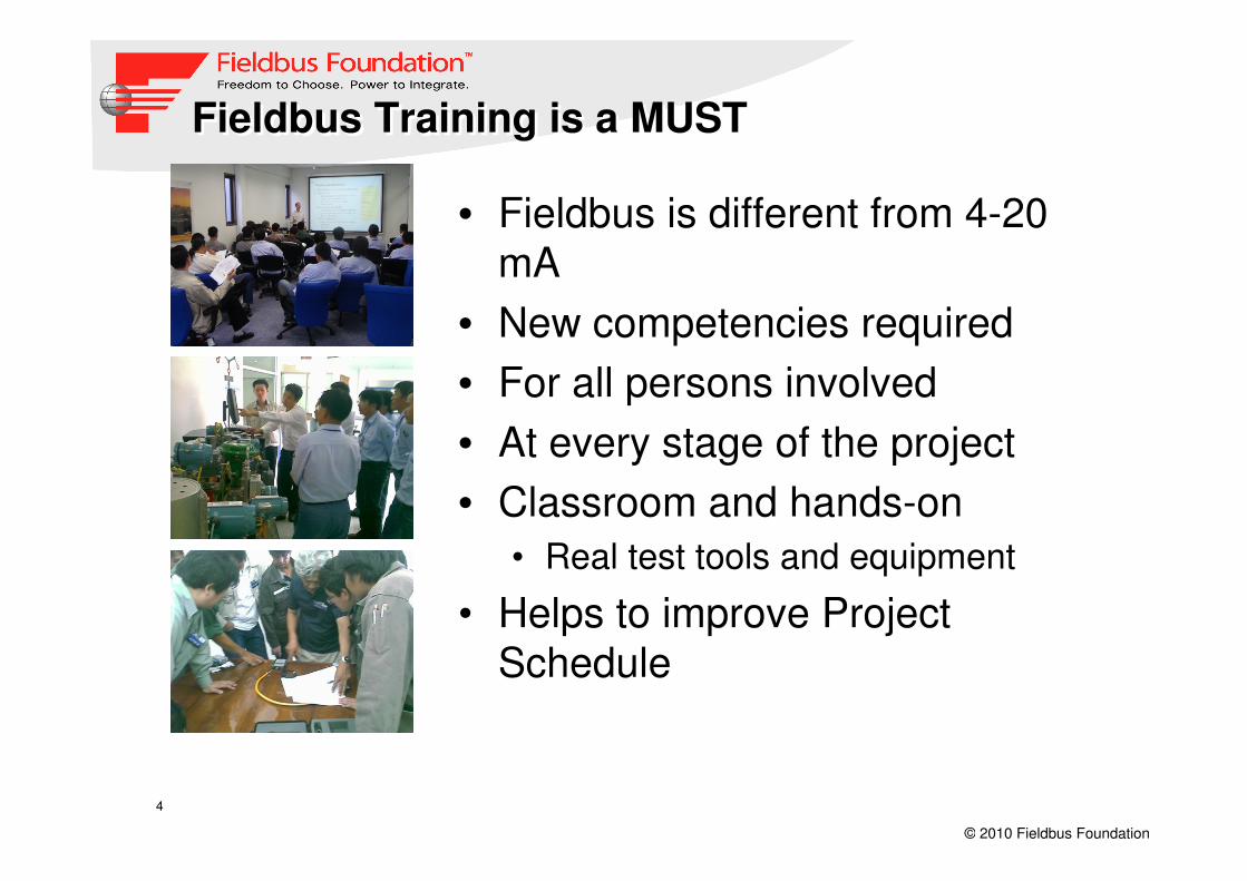
Fieldbus Training is a MUSTFieldbus Training is a MUST
• Fieldbus is different from 4-20
mA
• New competencies required
• For all persons involved
• At every stage of the project
• Classroom and hands-on
• Real test tools and equipment
• Helps to improve Project
Schedule
Page 5
5
© 2010 Fieldbus Foundation
Fieldbus Training is a MUSTFieldbus Training is a MUST
• Customized to project hardware and procedures
• Design engineers• Design Considerations
• Fieldbus segment design software
• Installation team• Lay cable and terminate
• Segment Checkout
• Device commissioning Team• Check bus parameters
• Connect devices & commission
• Troubleshooting using tools
Page 6
6
© 2010 Fieldbus Foundation
3 Ways to Do Closed Loop Digital Control
• Control in Controller
(CIC)
� Traditional way
• Control in the Field (CIF)
� Single loop integrity when used in conjunction with backup LAS
� Less communication
� Devices must be on the same bus
• Operator can't see
the difference
• 80/20 Rule
Transmitter
Valve
AI PID AO
Valve
Transmitter
AI PID AO
Transmitter Valve
Controller
AI PID AO
CIF
Technical
White
Paper
Available
CIF
Technical
White
Paper
Available
Page 7
7
© 2010 Fieldbus Foundation
ARC White paper on CIF
Page 8
8
© 2010 Fieldbus Foundation
Schedule “Time Table”CIF
Scheduled (Cyclic)
� Real-time block links
– Closed loop process
variables
– Controller output
Unscheduled (Acyclic)
� Alarms and Events
� Maintenance, Diagnostic, &
� Configuration
� Open loop monitoring
Macrocycle 250 ms
UnscheduledCV1
TX1
CV2
TX2
CV3
TX3
Macrocycle 250 ms
UnscheduledPID
AI
AO
PID
AI
AO
PID
AI
AO
PID
AI
AO
PID
AI
AO
PID
AI
AO
AI
AIL
ink
Lin
k
Lin
k
Lin
k
Lin
k
Lin
k
Lin
k30 ms
Open loop
monitoring
devices
Page 9
9
© 2010 Fieldbus Foundation
Communications Processing
AI PID AO
20ms
30ms
30ms
25ms
This sample loop on a segment results in a minimum 105 ms macrocycle time.
AI PID AO
20ms
30ms
30ms
25ms
> 105 ms
Page 10
10
© 2010 Fieldbus Foundation
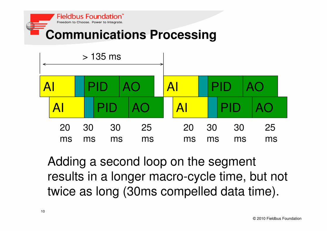
Communications Processing
Adding a second loop on the segment results in a longer macro-cycle time, but not twice as long (30ms compelled data time).
AI PID AO
20ms
30ms
30ms
25ms
AI PID AO
AI PID AO
20ms
30ms
30ms
25ms
AI PID AO
> 135 ms
Page 11
11
© 2010 Fieldbus Foundation
AutoTune
Analog Input
Analog Input
Transmitter
LCD
Diagnostics
DCS/Host
AI Application
Resource
Sensor Transducer
PID
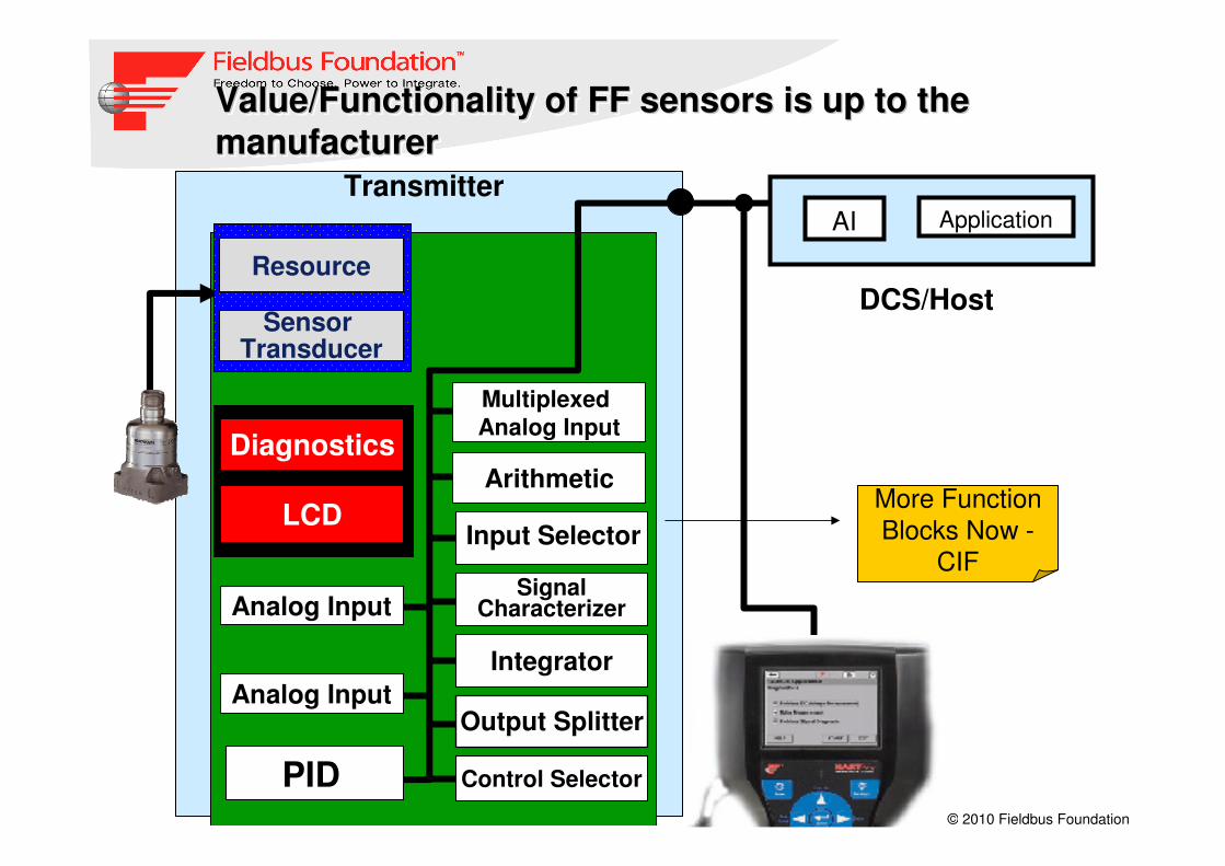
Value/Functionality of FF sensors is up to the manufacturer
Value/Functionality of FF sensors is up to the Value/Functionality of FF sensors is up to the
manufacturermanufacturer
Integrator
SignalCharacterizer
ArithmeticMore Function
Blocks Now -
CIF
Output Splitter
Control Selector
Input Selector
Multiplexed
Analog Input
Page 12
12
© 2010 Fieldbus Foundation
Assigning Fieldbus Devices to a Segment
Maximum 16 devices per segment
Recommended loading (one second
macrocycle)
� Total of 12 devices per segment
� Total of 3 control valves per segment
Devices should be placed on segments based
on location, control function and
reliability requirements
Page 13
13
© 2010 Fieldbus Foundation
Device Current ConsumptionDevice Current Consumption
� Average less than 17 mA� The lower the better
Manufacturer Description mA
Fisher Valve Positioner 18
Rosemount Pressure transmitter 17.5
Rosemount Temperature
transmitter
11
Rosemount Vortex flow meter 18.5
Rosemount Analytical pH analyzer 22
Micro Motion Coriolis mass flow
meter
11
Rosemount Analytical Oxygen analyzer 18
Page 14
14
© 2010 Fieldbus Foundation
Complete Range of Fieldbus DevicesComplete Range of Fieldbus DevicesPressure Pressure Machinery Health Electric On/Off Electric Modulating On/Off Pneumatic
Positioner
On/Off Pneumatic Coriolis Flow DP Flow Temperature Temperature Remote Indicator DI/DO
Multi Temperature Magnetic Flow Vortex Flow Amperometric pH Conductivity Amperometric
pH Conductivity O2 Yoko PressureRadar Level
Honeywell
Temperature
Radar Level
Hand Held
Valve Monitor
Pressure
O2 & Combustion Valve Manifold E&H Flow
Page 15
15
© 2010 Fieldbus Foundation
New Types of Ff devices to reduce CostsNew Types of Ff devices to reduce Costs
High Density Temperature Transmitter
Machinery Health Transmitter
8 DI and 4 DOWithout
fieldbus you
cannot benefit
from new
innovations
2 Channel Temperature Transmitter
8 Point Remote Indicator
Temperature Multiplexer
Page 16
16
© 2010 Fieldbus Foundation
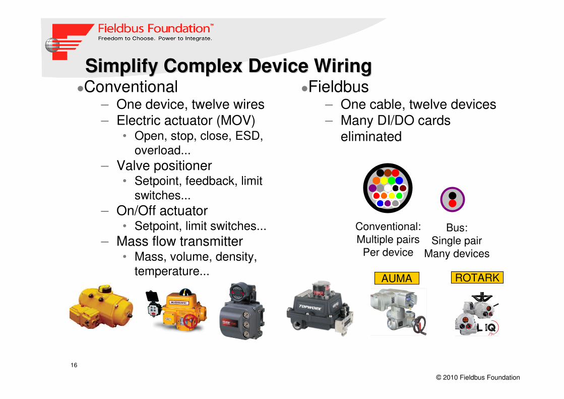
Simplify Complex Device WiringSimplify Complex Device Wiring�Conventional
– One device, twelve wires– Electric actuator (MOV)
• Open, stop, close, ESD,
overload...
– Valve positioner• Setpoint, feedback, limit
switches...
– On/Off actuator• Setpoint, limit switches...
– Mass flow transmitter• Mass, volume, density,
temperature...
�Fieldbus– One cable, twelve devices– Many DI/DO cards
eliminated
Conventional:
Multiple pairs
Per device
Bus:
Single pair
Many devices
AUMA ROTARK
Page 17
17
© 2010 Fieldbus Foundation
Instrument Functionality Instrument Functionality -- OnOn--Off valvesOff valves
Uses Single DO
Block
2-Wire device for power to both
Sensor Communication Module
and (2) Low power piezo pilots,
digital readback, alarms and
diagnostics
Page 18
18
© 2010 Fieldbus Foundation
Installation : Checkout fieldbus wiring
Systematic Approach
� Don’t rush
Follow procedures
� Grounding Checks
� Proper voltages
� Terminators Functioning
� Verify Results
Page 19
19
© 2010 Fieldbus Foundation
Resistance & Capacitance Verification
Conductor-to-conductor & conductor-to-shield
resistance checks
Conductor-to-ground/earth & shield-to-
ground/earth resistance checks
Cable capacitance checks
Test Expected Result
(+) to (-) conductor > 50 kohm
(+) to shield > 20 Mohm
(-) to shield > 20 Mohm
Shield to ground < 100 ohm
Page 20
20
© 2010 Fieldbus Foundation
Fieldbus Tester Tools: Relcom FBT6
Monitors:
� Voltage
� Peak noise
� Average noise
� Wiring
– Shield not shorted to signal
� Retransmits
– Communication errors
� Add/Drop
– Devices added/removed
� LAS signal
– Control system interface card
� Lowest signal
� Device count
Indicates OK/Bad for each test
Store 8 test results and upload to Excel
FBT6
Page 21
21
© 2010 Fieldbus Foundation
Fieldbus Tester Tools: Relcom FBT5
Validates wiring
� Injects signal
� Do not use in hazardous areas
� Automatically powers off after a few minutes
– To conserve battery
Page 22
22
© 2010 Fieldbus Foundation
Advanced Diagnostics
FieldConnex Advanced Diagnostic ModuleFieldConnex Advanced Diagnostic Module
– A single tool for commissioning, monitoring, and troubleshooting
– Versions to suit your every need
� Stationary ADM– Monitors four segments
– Integrated in Power Hub– Stand-alone motherboard
� Mobile ADM– Single segment monitoring– For any power supply
Page 23
23
© 2010 Fieldbus Foundation
MTL F809F onMTL F809F on--line monitoringline monitoring
� Monitors parameters on
8 fieldbus segments
� Reports parameters over FOUNDATION fieldbusTM H1
– Module is a Fieldbus device
� Diagnostic software– Integrated into Host
F809F
F800 system
Page 24
24
© 2010 Fieldbus Foundation
F809F measured parametersF809F measured parameters� Segment voltage� Signal voltage
– All devices– Address of device having lowest voltage
� Average and peak noise– Low frequency band– FF signalling band– High frequency band
� Fieldbus to shield short circuits– + to shield– - to shield
� Device retransmissions� Number of devices recognised on bus
� Address of LAS
Page 25
25
© 2010 Fieldbus Foundation
Summary
• Training from the start & at all stages
• Use of Control In the Field
• Maximize number of devices per segment
• Make use of the Ff products that will reduce
the number of devices, segments, wiring
• Use of Power Conditioners with Advanced
Diagnostics module for installation check
• Document Project Savings at the end of the
Project and share it with others
• Ff Technology for small to medium size
plants too.


![Profibus PA Fieldbus Display [ Revision 2 ] and Fieldbus ... Instruments... · Profibus PA Fieldbus Display [ Revision 2 ] and Fieldbus Indicator Fieldbus Interface Guide. ... Siemens](https://static.documents.pub/doc/80x56/5b2fe38e7f8b9ae16e8da83d/profibus-pa-fieldbus-display-revision-2-and-fieldbus-instruments.jpg)


