ORNL/TM-2014/59 Emissions and Performance Benchmarking of a Prototype Dimethyl Ether-Fueled Heavy-Duty Truck February 2014 Prepared by James P. Szybist Oak Ridge National Laboratory Samuel McLaughlin Volvo North America Suresh Iyer The Pennsylvania State University
Transcript
ORNL/TM-2014/59
Emissions and Performance Benchmarking of a Prototype Dimethyl Ether-Fueled Heavy-Duty Truck
February 2014 Prepared by James P. Szybist Oak Ridge National Laboratory Samuel McLaughlin Volvo North America Suresh Iyer The Pennsylvania State University
DOCUMENT AVAILABILITY Reports produced after January 1, 1996, are generally available free via the U.S. Department of Energy (DOE) Information Bridge. Web site http://www.osti.gov/bridge Reports produced before January 1, 1996, may be purchased by members of the public from the following source. National Technical Information Service 5285 Port Royal Road Springfield, VA 22161 Telephone 703-605-6000 (1-800-553-6847) TDD 703-487-4639 Fax 703-605-6900 E-mail [email protected] Web site http://www.ntis.gov/support/ordernowabout.htm Reports are available to DOE employees, DOE contractors, Energy Technology Data Exchange (ETDE) representatives, and International Nuclear Information System (INIS) representatives from the following source. Office of Scientific and Technical Information P.O. Box 62 Oak Ridge, TN 37831 Telephone 865-576-8401 Fax 865-576-5728 E-mail [email protected] Web site http://www.osti.gov/contact.html
This report was prepared as an account of work sponsored by an agency of the United States Government. Neither the United States Government nor any agency thereof, nor any of their employees, makes any warranty, express or implied, or assumes any legal liability or responsibility for the accuracy, completeness, or usefulness of any information, apparatus, product, or process disclosed, or represents that its use would not infringe privately owned rights. Reference herein to any specific commercial product, process, or service by trade name, trademark, manufacturer, or otherwise, does not necessarily constitute or imply its endorsement, recommendation, or favoring by the United States Government or any agency thereof. The views and opinions of authors expressed herein do not necessarily state or reflect those of the United States Government or any agency thereof.
APPENDIX A. Penn State Report on Testing of Volvo Prototype DME Truck .............................. 12
APPENDIX B. DME - Another Choice Alternative Fuel..................................................................23
v
ACKNOWLEDGMENTS
This report and the work described were sponsored by the U.S. Department of Energy (DOE) Office of Energy Efficiency and Renewable Energy (EERE) Vehicle Technologies Office. The authors gratefully acknowledge the support and direction of Kevin Stork and Steve Przesmitzki at DOE.
This benchmarking data was collected in cooperation with Volvo North America. The authors are grateful to Skip Yeakel and colleagues for making the prototype DME truck available at the Penn State University facility for testing so that benchmarking data could be collected. The authors are also grateful to Brian West, Ron Graves, and Robert Wagner at ORNL for their support and guidance on this project.
vii
EXECUTIVE SUMMARY
In cooperation with Volvo, ORNL commissioned the benchmarking of the emissions and performance data from a heavy-duty truck with a prototype engine fueled with dimethyl ether (DME). The prototype engine is equipped with a 3 way catalyst, but is not equipped with a diesel particulate filter or lean NOx aftertreatment. The benchmarking took place at Penn State University’s heavy duty chassis laboratory, which is equipped with a full-flow dilution tunnel. The benchmarking test consisted of duplicate tests of a 60 mph steady cruise and the cruise portion of the Heavy Heavy-Duty Diesel Truck (HHDDT) driving schedule, with complete details of the Penn State testing reported in Appendix A. The results from the DME truck are compared to the results from another Volvo truck with a conventional diesel engine collected at the same chassis laboratory facility in 2011. The results show that the prototype DME truck performed well over the course of the testing with no significant failures or obstacles. The DME results were repeatable over the duplicate tests for both the 60 mph cruise and the cruise portion of the HHDDT driving schedule. The prototype DME truck was calibrated to meet the Euro V emission standards, and the emission measurements confirmed that NOx, PM, CO, and HC were below the expected level for vehicles meeting Euro V emissions. The PM emissions for DME were sufficiently low to approach the detection limit, and were a minimum of an order of magnitude below the 2010 U.S. emission standard without the use of a diesel particulate filter. In addition, while methane is not currently regulated for heavy-duty compression ignition vehicles in either the U.S. or Europe, the methane emissions were an order of magnitude below what is permissible for the heavy duty natural gas vehicles for the Euro V emission standard. The transient nature of the HHDDT driving scheduled produced high spikes in both unburned HC and CO emissions for the prototype DME truck. While these emissions spikes did not lead to emissions exceedances, they do illustrate that further reductions in emissions and possibly fuel economy could be realized with further hardware and controls development. The fuel economy for the prototype DME truck was compared to that of a conventional, diesel truck and found to be similar on an energy-equivalent basis given the specification differences of the two vehicles. The prototype DME truck had an average diesel-equivalent fuel economy of 5.3 mpg, while the diesel truck had a fuel economy of 6.0 mpg. Given that the DME truck has two drive axles, it has a lower driveline efficiency than the single-drive axle diesel truck. In addition to the powertrain efficiency differences there are number of additional differences between the DME and diesel vehicles, such as the emission calibration and the engine displacement. As a result, it can be concluded that the engines produced a similar level of efficiency. The tests demonstrate the near-term viability of DME in heavy-duty applications. The truck performed well under real-world driving conditions and emissions were within the targeted emission standards. The tests confirmed that no PM aftertreatment is necessary when using DME as the fuel. Further NOx emissions reductions are feasible with the use of NOx aftertreatment, a pathway which could also enable a higher efficiency combustion strategy.
1
1. BACKGROUND
Dimethyl ether (DME) is a fuel that is known to have a number of desirable fuel properties for compression ignition engines. The fuel properties of diesel fuel and DME are compared in Table 1, where the fuel property data is taken from Arcoumanis et al. [1].
Table 1. Fuel properties of DME and diesel fuel [1].
DME Diesel Fuel Carbon content (mass %) 52.2 86 Hydrogen content (mass %) 13 14 Oxygen content (mass %) 34.8 0 Critical temperatrure (K) 400 708 Critical pressure (MPa) 5.37 3.00 Critical density (kg/m3) 259 - Liquid density (kg/m3) 667 831 Cetane number > 55 40-50 Auto-ignition temperature (K) 508 523 Stoichiometric air/fuel ratio 9.0 14.6 Boiling point at 1 atm (K) 248.1 450-643 Enthalpy of vaporization (kJ/kg) 467.13 300 Lower heating value (MJ/kg) 27.6 42.5 Gaseous specific heat capacity (kJ/kg-K) 2.99 1.7 Ignition limits (vol% in air) 3.4/18.6 0.6/6.5 Modulus of elasticity (N/m2) 6.37E+08 14.86E+08 Kinematic viscosity of liquid (cSt) <0.1 3 Surface tension (N/m) 0.012 0.027 Vapor pressure at 298K (kPa) 530 <<10
Of particular note is that the cetane number of DME is higher than that of diesel fuel, indicating that it has superior ignitibility in compression ignition engines. Also noteworthy is the high oxygen content of DME, 34.8%. While the high oxygen content reduces the lower heating value of the fuel (27.6 MJ/kg for DME compared to 42.6 MJ/kg for diesel fuel), the high oxygen content is also attributed to producing very low particulate matter and soot emission [2]. In fact, Miyamoto et al. showed that while the overall oxygen content is important, the ether functional group provides an additional advantage because the fuel has no carbon-carbon bonds [3].
Diesel engines traditionally have a tradeoff between NOx and particulate matter emissions, meaning that whatever in-cylinder measures are taken to reduce NOx emissions have the unintended effect of increasing particulate matter. Because DME does not produce particulate matter, such a tradeoff does not
1. Arcoumanis, C., Bae, C., Crookes, R., Kinoshita, E., “The Potential of Di-methyl Ether (DME) as an Alternative Fuel for Compression-Ignition Engines: A Review,” Fuel, 87, pp. 1014-1030, 2008. 2. Ogawa, H., Miyamoto, N., Yagi, M., “Chemical-kinetic Analysis on PAH Formation Mechanisms of Oxygenated Fuels.” SAE Technical Paper 2003-01-3190, 2003. 3. Miyamoto, H., Ogawa, H., Arima, T., Miyakawa, K., “Improvement of diesel combustion and emissions with various oxygenated fuel additives.” SAE Technical Paper 962115, 1996.
2
exist and much more aggressive in-cylinder measures can be taken, particularly in regards to retarding combustion phasing and high levels of EGR, as in Salsing et al. [4].
While there are advantages of the high cetane number and high oxygen content, DME is a gas at atmospheric pressure and thus requires special fuel handling considerations. Primarily this means that the fuel tanks have to be pressurized to approximately 75 psi. The materials and amount of pressurization for DME weigh and cost less than the fuel tank systems required for compressed natural gas (CNG) and liquefied natural gas (LNG), but the pressurized fueling system does weigh and cost more than that of a conventional diesel truck [5, Appendix B].
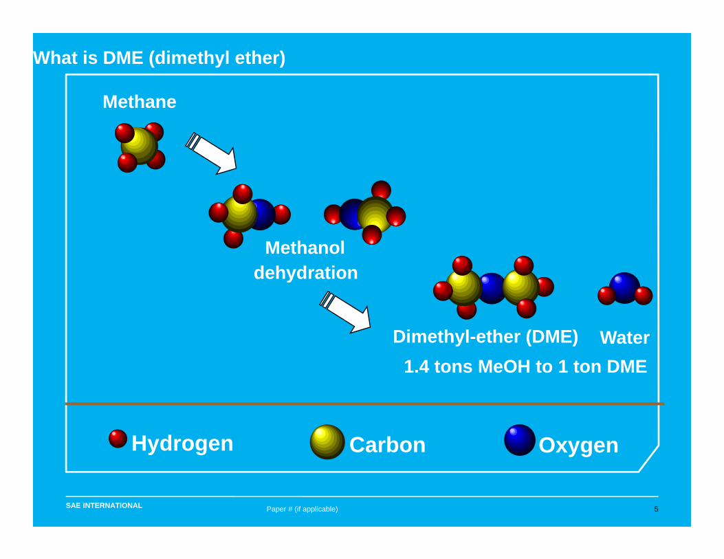
DME is an isomer of ethanol, meaning that they both have the same molecular weight. As a result they have the same stoichiometric air/fuel ratio and similar energy content on a mass basis. However, they are produced from different feedstocks. Ethanol is primarily produced from fermentation of sugar and starch crops (primarily corn in the U.S.), with cellulosic processes expected to come online in the near future. DME is produced synthetically from methanol dehydration, and methanol is produced from syngas. While the source of the syn gas can be either renewable or fossil, the newly found abundance of natural gas in the U.S. makes it the most likely source material for DME on a widespread basis. Oberon Fuels is a company that is currently pursuing a concept of a small-scale plant to make DME from natural gas on-site to have a dispersed infrastructure for DME [6], thereby providing a possible path forward to the widespread use of DME.
The intent of this report is to provide a small amount of background information on DME rather than to provide a comprehensive literature review. For more in-depth literature reviews refer to Arcoumanis et al. [1].
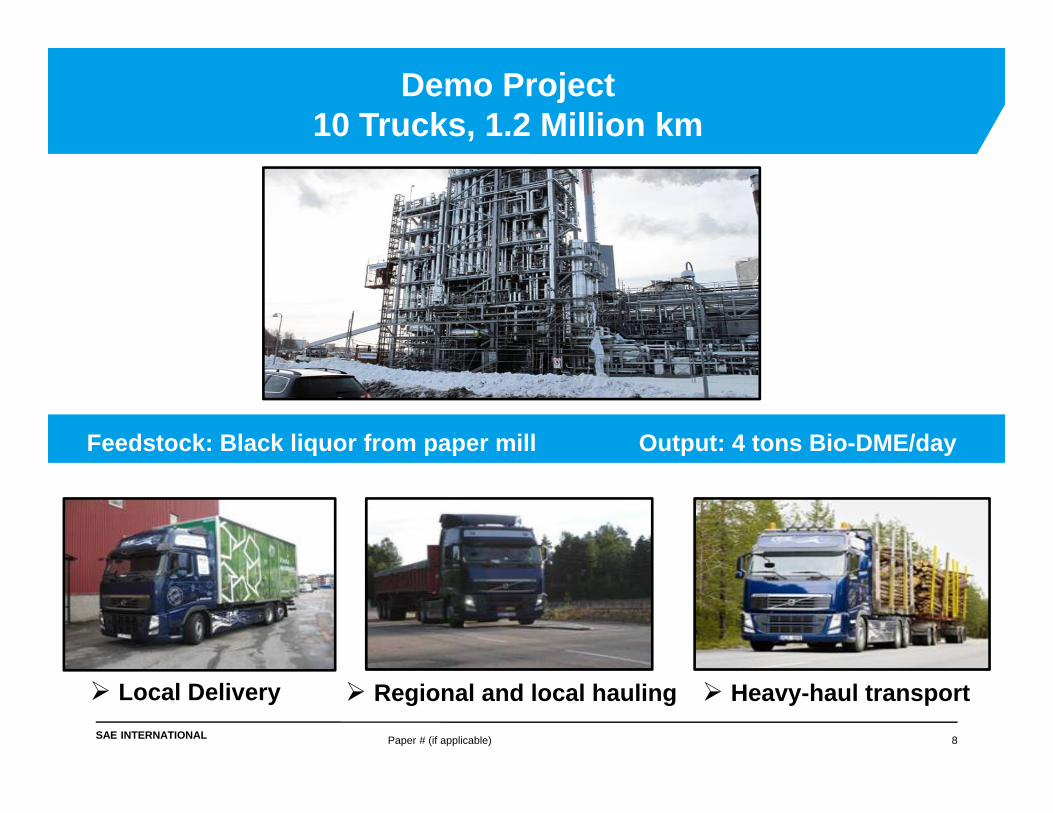
Volvo has had significant development effort aimed at producing a DME engine, including a demonstration project in Europe that includes 10 trucks with a variety of duty cycles that have logged a combined 1.2 million kilometers [5]. In 2013 Volvo introduced 4 prototype DME trucks in the U.S. and announced plans to begin commercial offerings of DME trucks beginning in 2015 [7]. ORNL had the opportunity to benchmark the efficiency and performance of one of these 4 prototype DME trucks at the Pennsylvania State University’s heavy-duty chassis laboratory facility on behalf of the U.S. Department of Energy. The results of the heavy-duty truck benchmarking are contained in the following sections.
4. Salsing, H. and Denbratt, I., "Performance of a Heavy Duty DME Diesel Engine - an Experimental Study," SAE Technical Paper 2007-01-4167, 2007, doi:10.4271/2007-01-4167. 5. McLaughlin, S., “DME – Another Choice Alternative Fuel,” SAE Presentation, 2013, also included as Appendix B. 6. Oberon Fuels Website, accessed January, 2014. http://www.oberonfuels.com/technology/oberon-process/ 7. Volvo Press Release, Accessed January, 2014. http://www.volvogroup.com/group/global/en-gb/volvo%20group/worldwide/Volvo-Group-North-America/_layouts/CWP.Internet.VolvoCom/NewsItem.aspx?News.ItemId=143305&News.Language=en-gb
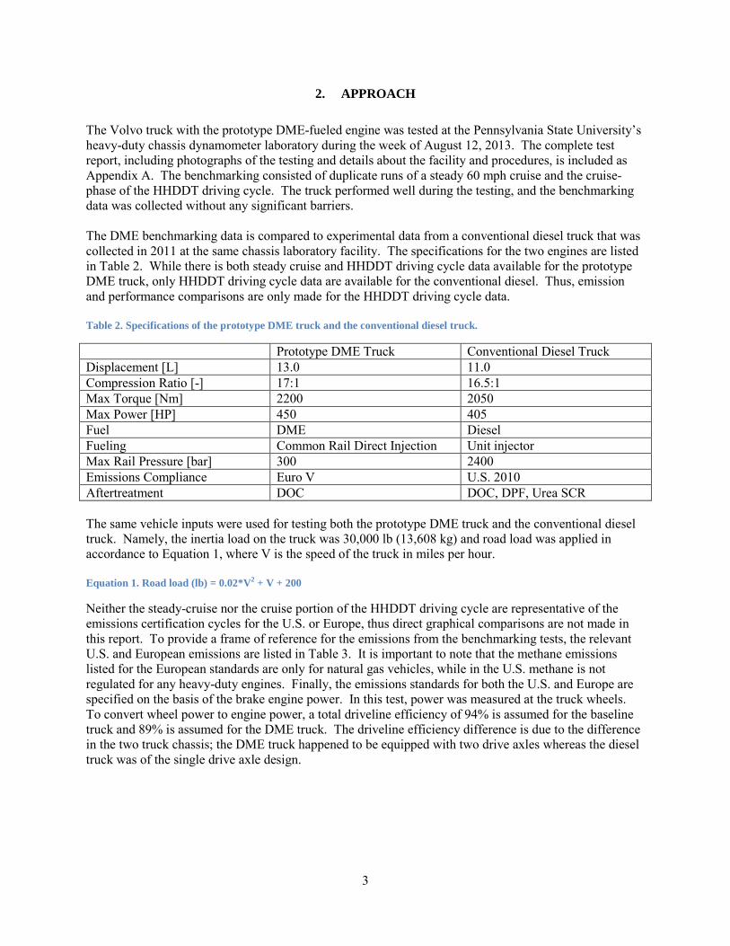
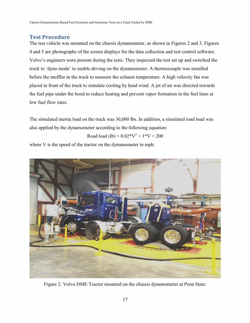
The Volvo truck with the prototype DME-fueled engine was tested at the Pennsylvania State University’s heavy-duty chassis dynamometer laboratory during the week of August 12, 2013. The complete test report, including photographs of the testing and details about the facility and procedures, is included as Appendix A. The benchmarking consisted of duplicate runs of a steady 60 mph cruise and the cruise-phase of the HHDDT driving cycle. The truck performed well during the testing, and the benchmarking data was collected without any significant barriers. The DME benchmarking data is compared to experimental data from a conventional diesel truck that was collected in 2011 at the same chassis laboratory facility. The specifications for the two engines are listed in Table 2. While there is both steady cruise and HHDDT driving cycle data available for the prototype DME truck, only HHDDT driving cycle data are available for the conventional diesel. Thus, emission and performance comparisons are only made for the HHDDT driving cycle data. Table 2. Specifications of the prototype DME truck and the conventional diesel truck.
Prototype DME Truck Conventional Diesel Truck Displacement [L] 13.0 11.0 Compression Ratio [-] 17:1 16.5:1 Max Torque [Nm] 2200 2050 Max Power [HP] 450 405 Fuel DME Diesel Fueling Common Rail Direct Injection Unit injector Max Rail Pressure [bar] 300 2400 Emissions Compliance Euro V U.S. 2010 Aftertreatment DOC DOC, DPF, Urea SCR The same vehicle inputs were used for testing both the prototype DME truck and the conventional diesel truck. Namely, the inertia load on the truck was 30,000 lb (13,608 kg) and road load was applied in accordance to Equation 1, where V is the speed of the truck in miles per hour. Equation 1. Road load (lb) = 0.02*V2 + V + 200
Neither the steady-cruise nor the cruise portion of the HHDDT driving cycle are representative of the emissions certification cycles for the U.S. or Europe, thus direct graphical comparisons are not made in this report. To provide a frame of reference for the emissions from the benchmarking tests, the relevant U.S. and European emissions are listed in Table 3. It is important to note that the methane emissions listed for the European standards are only for natural gas vehicles, while in the U.S. methane is not regulated for any heavy-duty engines. Finally, the emissions standards for both the U.S. and Europe are specified on the basis of the brake engine power. In this test, power was measured at the truck wheels. To convert wheel power to engine power, a total driveline efficiency of 94% is assumed for the baseline truck and 89% is assumed for the DME truck. The driveline efficiency difference is due to the difference in the two truck chassis; the DME truck happened to be equipped with two drive axles whereas the diesel truck was of the single drive axle design.
4
Table 3. European and U.S. regulated emissions for heavy duty engines [8].
PM [g/kW-h ] 0.022 0.022 0.0134 1. U.S. 2010 emission standards are converted from g/bhp-h
2. Diesel vehicles on the ESC/ELR test cycle 3. Natural gas vehicles on the ETC test cycle 4. Diesel vehicle on the EPA Transient Test Procedure
3. RESULTS
3.1 STEADY CRUISE RESULTS
The steady cruise results for the prototype DME truck are presented in Figure 1, showing the truck speed, power, and exhaust temperature across the duration of the 550 sec steady cruise test. It can be seen that the truck speed and power are held nearly constant throughout the duration of the test. The exhaust temperature plot shows that it takes approximately 3 minutes for the exhaust temperature to arrive at a steady state value for this condition. The slow approach to equilibrium may be, in part, an artifact of the rising engine compartment temperature while the truck was on the chassis dynamometer. Additionally, it shows that the exhaust temperature for the DME truck is very low (< 300°C) for an engine condition that exceeds 50% of the full load power for the engine. The low exhaust temperature can be attributed to the high EGR strategy that is employed by this prototype truck to reduce engine-out NOx emissions, and a higher exhaust temperature would be expected with a strategy that uses less EGR and urea-SCR to control NOx emissions.
Figure 1. Speed, power, and exhaust temperature for the duplicate steady 60 mph cruise tests for the DME truck.
The NOx emissions are shown Figure 2 for the two repeats of the steady cruise condition. It is observed that the NOx emissions increase steadily over duration of the test, suggesting that the engine did not come
8. Delphi, “Worldwide Emissions Standards: Heavy Duty and Off-Highway Vehicles,” 2013-2014, http://delphi.com/emissions-hd.
to a true thermal equilibrium. Although this steady cruise condition is not representative of the emissions certification driving cycle, the NOx emissions are below the emissions standards for Euro IV (3.5 g/kWh) and Euro V (2.0 g/kWh) without the use of any NOx aftertreatment devices. It is not surprising that the NOx emissions are higher than the U.S. 2010 standards given that the 0.27 g/kWh target is currently only being met with the use of lean NOx aftertreatment equipment (primarily urea SCR).
Figure 2. NOx emissions for the two repeats of a 60 mph cruise for the prototype DME truck. Note that these emissions have been adjusted to an engine brake power basis with the assumption of 89% total driveline efficiency.
The total unburned HC emissions are shown in Figure 3 for both steady cruise repeats for the DME truck. With the exception of an excursion of HC emissions near the end of each test, the HC emissions are very low, below 0.02 g/kWh. This level of total HC emissions are more than an order of magnitude below both the Euro IV and Euro V requirements (0.46g/kWh) and the U.S. emission standards (0.19 g/kWh). It should be noted that the HC emissions in Figure 3 includes methane, and the U.S. emission standard of 0.19 g/kWh is for non-methane hydrocarbons (NMHC). It is important to note that this HC measurement is performed using a flame ionization detector (FID), and while this is the industry-standard technique for engine emission testing, oxygenated species such as DME typically have response factors that are lower than that of the propane calibration gas. As a result, the unburned HC emissions are likely biased low by an unknown amount. The net result of this bias is undetermined.
Figure 3. Unburned HC emissions for the two repeats of a 60 mph cruise for the prototype DME truck. Note that these emissions have been adjusted to an engine brake power basis with the assumption of 89% total driveline efficiency.
Methane emissions are shown in Figure 4 for the two repeats of the steady cruise for the DME truck. It is notable that while emissions of methane are low, less than 0.02 g/kWh, methane emissions do comprise the majority of HC emissions from the engine. Methane emissions are not regulated for compression ignition vehicles in either the U.S. or in Europe. There is a methane emission standard for heavy-duty natural gas engines under the Euro IV and Euro V standards of 1.1 g/kWh. Although this standard is not directly comparable, it is noteworthy that the methane emissions from the DME truck are nearly two orders of magnitude lower. Thus, while methane emissions are present, they are are insignificant compared to the emissions permitted from heavy-duty natural gas engines.
0
1
2
3
4
0 100 200 300 400 500 600
Steady Cruise 1Steady Cruise 2
NO
x Em
issi
ons
[ g/k
Wh
]
Time [s]
0
0.1
0.2
0.3
0.4
0 100 200 300 400 500 600
Steady Cruise 1Steady Cruise 2
HC
Em
issi
ons
[ g/k
Wh
]
Time [s]
6
Figure 4. Methane emissions for the two repeats of a 60 mph cruise for the prototype DME truck. Note that these emissions have been adjusted to an engine brake power basis with the assumption of 89% total driveline efficiency.
Finally, the particle emissions for the prototype DME truck are extremely low, 0.0015 g/kWh without the use of a DPF. This result is nearly an order of magnitude lower than the current U.S. diesel emission standards of 0.01 g/HP-h (0.0134 g/kWh), a standard that is only being met in the U.S. with the use of DPF aftertreatment devices. Thus, this finding confirms that PM aftertreatment is not required when fueling with DME. It is also worth noting that the measured emissions of PM are approaching the detection limits of the instruments used.
3.2 HHDDT Cruise Phase Emissions and Performance
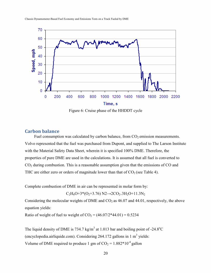
The Heavy Heavy-Duty Diesel Truck (HHDDT) Schedule is a driving cycle that was developed by the California Air Resources Board [9]. The schedule consists of an idle portion, a creep portion, a transient portion, and a high speed cruise. The prototype DME truck was tested only in the high speed cruise portion of the driving schedule. The speed-time trace from the two repeats of the prototype DME truck and the diesel truck are shown in Figure 5. Due to differences in the location of exhaust gas temperature probes on the two trucks, no comparisons of exhaust gas temperature can be made.
Figure 5. Speed-time trace for the cruise portion of the HHDDT schedule.
The NOx emissions for the prototype DME truck are shown as a function of time in Figure 6(a). There is a spike in NOx emissions for both of the DME repeats and for the diesel test that corresponds with the acceleration at 1000 seconds from a stop to more than 50 miles-per-hour. The spike in NOx emissions from the DME truck is higher than for the diesel truck. Once the initial acceleration is complete, NOx emissions for the DME truck fluctuate between about 30 and 100 mg/s. In contrast, the NOx emissions
9. Heavy Heavy-Duty Diesel Truck (HHDDT) chassis dynamometer schedule, accessed from DieselNet on December 11, 2013. http://www.dieselnet.com/standards/cycles/hhddt.php
from the diesel truck steadily decrease. The net result, which can be seen in the cumulative emissions in Figure 6(b), is that the NOx emissions are a factor of 3 higher for the prototype DME truck. A difference in NOx emissions was expected between these two vehicles because the prototype DME truck was calibrated to be compliant with Euro V NOx emissions whereas the diesel truck has urea SCR NOx aftertreatment and is compliant with the U.S. 2010 NOx emission standards. While the HHDDT driving cycle is not an emissions certification cycle, the emission measurements here compare favorably to the emission standards in Table 3.
Figure 6. NOx emissions for the prototype DME truck and for the conventional diesel truck for (a) emissions as a function of time, and (b) cumulative emissions on an engine-specific basis corrected for a 89% total driveline efficiency in the DME truck and 94% driveline efficiency in the diesel truck.
The total unburned HC emissions are shown as a function of time in Figure 7(a), and for the cumulative driving schedule in Figure 7(b). For the prototype DME truck, the baseline level of HC emissions is low, but there are a number of short duration spikes that are in excess of an order of magnitude higher than the baseline level. While the cause of the unburned HC spikes has not been determined, it is noteworthy that this behavior was not observed for the steady cruise data in Figure 3. This prototype version of the DME truck does not contain fully developed transient engine maps, thus it is likely that this behavior would be negated by additional development of the engine controller, as it would be for a fully-developed, commercially-available engine or vehicle. Nonetheless, the cumulative emissions shown in Figure 7(b) are significantly below both the European and the U.S. emission limits for HC emissions, with the caveat that the HHDDT driving cycle is not an emission certification cycle.
Figure 7. Unburned HC emissions for the prototype DME truck and for the conventional diesel truck for (a) emissions as a function of time, and (b) cumulative emissions on an engine-specific basis corrected for a 89% total driveline efficiency in the DME truck and 94% driveline efficiency in the diesel truck.
The CO emissions are shown as a function of time in Figure 8(a). Under the 60 mph steady-cruise conditions the CO emissions were below the detection limit, and are therefore not shown. However,
0
100
200
300
400
500
600
1000 1500 2000 2500 3000
DME #1DME #2Diesel
NO
x Em
issi
ons
[ mg/
s ]
Time [s]
1.59
1.93
0.60
0
0.5
1
1.5
2
2.5
DME #1 DME #2 Diesel
NO
x [ g
/kW
h ]
020406080
100120140160
1000 1500 2000 2500 3000
DME #1DME #2Diesel
HC
Em
issi
ons
[ mg/
s ]
Time [s]
0.0775 0.0729
0.00030
0.02
0.04
0.06
0.08
0.1
DME #1 DME #2 Diesel
Unb
urne
d HC
[ g/
kWh
]
(a) (b)
(b) (a)
8
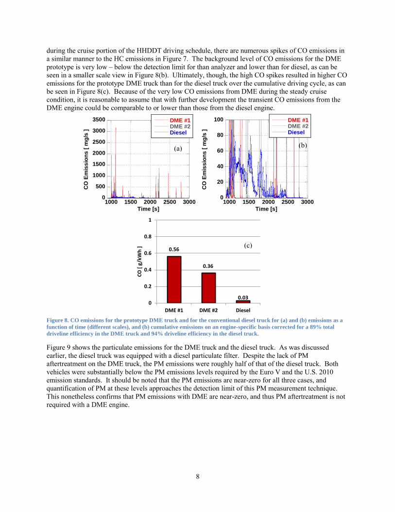
during the cruise portion of the HHDDT driving schedule, there are numerous spikes of CO emissions in a similar manner to the HC emissions in Figure 7. The background level of CO emissions for the DME prototype is very low – below the detection limit for than analyzer and lower than for diesel, as can be seen in a smaller scale view in Figure 8(b). Ultimately, though, the high CO spikes resulted in higher CO emissions for the prototype DME truck than for the diesel truck over the cumulative driving cycle, as can be seen in Figure 8(c). Because of the very low CO emissions from DME during the steady cruise condition, it is reasonable to assume that with further development the transient CO emissions from the DME engine could be comparable to or lower than those from the diesel engine.
Figure 8. CO emissions for the prototype DME truck and for the conventional diesel truck for (a) and (b) emissions as a function of time (different scales), and (b) cumulative emissions on an engine-specific basis corrected for a 89% total driveline efficiency in the DME truck and 94% driveline efficiency in the diesel truck.
Figure 9 shows the particulate emissions for the DME truck and the diesel truck. As was discussed earlier, the diesel truck was equipped with a diesel particulate filter. Despite the lack of PM aftertreatment on the DME truck, the PM emissions were roughly half of that of the diesel truck. Both vehicles were substantially below the PM emissions levels required by the Euro V and the U.S. 2010 emission standards. It should be noted that the PM emissions are near-zero for all three cases, and quantification of PM at these levels approaches the detection limit of this PM measurement technique. This nonetheless confirms that PM emissions with DME are near-zero, and thus PM aftertreatment is not required with a DME engine.
0
500
1000
1500
2000
2500
3000
3500
1000 1500 2000 2500 3000
DME #1DME #2Diesel
CO
Em
issi
ons
[ mg/
s ]
Time [s]
0
20
40
60
80
100
1000 1500 2000 2500 3000
DME #1DME #2Diesel
CO
Em
issi
ons
[ mg/
s ]
Time [s]
0.56
0.36
0.030
0.2
0.4
0.6
0.8
1
DME #1 DME #2 Diesel
CO [
g/kW
h ]
(a) (b)
(c)
9
Figure 9. Particulate matter emissions for the prototype DME truck and for the conventional diesel truck on an engine-specific basis corrected for a 89% total driveline efficiency in the DME truck and 94% driveline efficiency in the diesel truck.
Finally, the fuel consumption of the prototype DME truck can be compared to the diesel truck. CO2 emissions were measured directly from the dilution tunnel as part of the HHDDT driving cycle, but in order to convert this measurement into a miles-per-gallon fuel economy, fuel properties have to be assumed for both the diesel and DME. The properties listed in Table 1 were used for the fuel economy calculations, the results of which are presented in Figure 10. Figure 10(a) shows that the fuel economy of DME is less than half that of diesel fuel. Lower fuel economy is expected because of the reduced volumetric energy density for DME. Figure 10(b) shows the diesel-equivalent fuel economy for the prototype DME truck and the diesel truck. Once corrected for the energy density, the fuel economy for the DME truck is nearly in-line with the fuel economy of the diesel truck. However, there is still a disadvantage for the DME fuel economy with a reduction from 6.02 mpg to an average of 5.30 mpg. This difference can be attributed to a number of factors, the first of which is that there are significant vehicle differences. The DME truck has a lower mechanical driveline efficiency than the diesel truck that it was compared to, thus biasing the fuel economy low due to the additional drive axle. Second, the properties of the diesel fuel from the diesel test were assumed, as no fuel analysis data was available. Next, the diesel engine and prototype DME engine were calibrated to meet different emission standards. Specifically, the prototype DME truck used a strategy of in-cylinder NOx control, which likely requires late combustion phasing and high levels of EGR, both of which can reduce engine efficiency. Finally, the spikes in HC and CO emission throughout the HHDDT suggest that there could be further development of the combustion and control strategy for the prototype DME truck, possibly resulting in an increase in fuel economy.
0.00042 0.00042
0.00098
0
0.0005
0.001
0.0015
0.002
DME #1 DME #2 DieselPM
[ g/
kWh
]
10
Figure 10. Fuel economy for the prototype DME truck and for the diesel truck. (a) raw fuel economy, (b) diesel equivalent fuel economy.
2.74 2.72
6.02
0
1
2
3
4
5
6
7
DME #1 DME #2 Diesel
Fuel
Eco
nom
y [ m
pg ] 5.32 5.28
6.02
0
1
2
3
4
5
6
7
DME #1 DME #2 Diesel
Fuel
Eco
nom
y
[ D
iese
l Equ
ival
ent m
pg ]
(a) (b)
11
4. CONCLUSIONS
In partnership with Volvo and Penn State University, benchmarking of emissions and fuel economy of a prototype DME truck calibrated for Euro V emissions has been conducted on the Penn State heavy-duty vehicle dynamometer. Results for a U.S.-legal, 2010-compliant diesel truck tested under similar conditions at the same facility are available for comparison. Review of the available data leads to the following conclusions:
• NOx emissions were within the expected range for the prototype DME truck based on the emission standard for which the engine was calibrated (Euro V). This NOx emission level was met without the use of NOx aftertreatment. Further NOx reductions are feasible with the use of NOx aftertreatment to enable compliance with the U.S. 2010 emission standards.
• The prototype DME truck produces spikes of HC emissions throughout the HHDDT driving schedule. As a result, the HC emissions exceeded the conventional diesel truck by two orders of magnitude. Nonetheless, HC emissions were within the expected range for a truck compliant with the Euro V emission standard. Reductions of the HC spikes are feasible with additional calibration and hardware development.
o While methane emissions are not currently regulated in either the U.S. or in Europe for compression ignition engines, the methane emissions were on average an order of magnitude below the Euro V standard for heavy duty natural gas engines.
• Under the steady-cruise conditions the CO emissions were below the detection limit. However, during the HHDDT driving schedule, there were frequent spikes in CO emission in a manner similar to the HC emissions. As a result, CO emissions for the DME truck were an order of magnitude higher for the DME truck than for the conventional diesel. Reductions of the CO spikes are feasible with additional calibration and hardware development.
• The diesel-equivalent fuel economy was measured to be approximately 12% lower for the two-drive axle DME vehicle than for the single-drive-axle diesel vehicle (5.3 mpg vs. 6.02 mpg). Given the numerous differences between the emissions level, engine and vehicle configurations whereby the DME mechanical efficiency has at least a 4% disadvantage, it can be concluded that the energy efficiency between the two engines is similar.
12
APPENDIX A. Penn State Report on Testing of Volvo Prototype DME Truck
CHASSIS DYNAMOMETER BASED FUEL ECONOMY AND EMISSIONS TESTS ON A TRUCK FUELED BY DME Project Sponsored by Battelle - Oak Ridge National Laboratory Oak Ridge, TN Contact: James P. Szybist
Di-Methyl Ether Fueled Truck Sponsored by Volvo Group Truck Technology
Hagerstown, PA Contact: Samuel Mclaughlin
FINAL REPORT, September 16, 2013
Principal Investigator Dr. Suresh Iyer LTI Report Number 2014-02
The Pennsylvania State University Transportation Research Building
University Park, PA 16802-4710 (814) 865-1891 www.pti.psu.edu
Sampling probes (raw and dilute) 10 LPM The accuracy specifications of different analyzers used in the measurements is shown in Table 3. The two venturi flow meters have a specified uncertainty of 0.3% of reading.
Table 3. Specification of different gas analyzers.
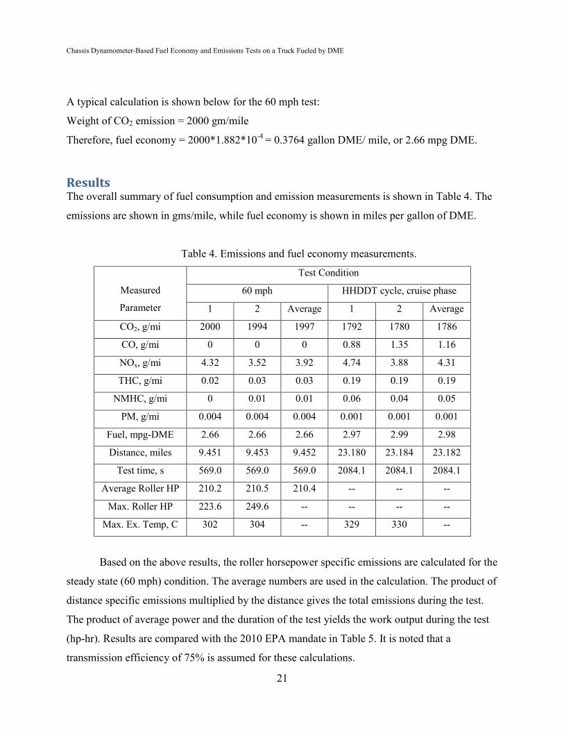
Results The overall summary of fuel consumption and emission measurements is shown in Table 4. The
emissions are shown in gms/mile, while fuel economy is shown in miles per gallon of DME.
Table 4. Emissions and fuel economy measurements.
Measured
Parameter
Test Condition
60 mph HHDDT cycle, cruise phase
1 2 Average 1 2 Average
CO2, g/mi 2000 1994 1997 1792 1780 1786
CO, g/mi 0 0 0 0.88 1.35 1.16
NOx, g/mi 4.32 3.52 3.92 4.74 3.88 4.31
THC, g/mi 0.02 0.03 0.03 0.19 0.19 0.19
NMHC, g/mi 0 0.01 0.01 0.06 0.04 0.05
PM, g/mi 0.004 0.004 0.004 0.001 0.001 0.001
Fuel, mpg-DME 2.66 2.66 2.66 2.97 2.99 2.98
Distance, miles 9.451 9.453 9.452 23.180 23.184 23.182
Test time, s 569.0 569.0 569.0 2084.1 2084.1 2084.1
Average Roller HP 210.2 210.5 210.4 -- -- --
Max. Roller HP 223.6 249.6 -- -- -- --
Max. Ex. Temp, C 302 304 -- 329 330 --
Based on the above results, the roller horsepower specific emissions are calculated for the
steady state (60 mph) condition. The average numbers are used in the calculation. The product of
distance specific emissions multiplied by the distance gives the total emissions during the test.
The product of average power and the duration of the test yields the work output during the test
(hp-hr). Results are compared with the 2010 EPA mandate in Table 5. It is noted that a
transmission efficiency of 75% is assumed for these calculations.
Chassis Dynamometer-Based Fuel Economy and Emissions Tests on a Truck Fueled by DME
22
Table 5: Calculated roller horsepower specific emissions
Results are for average data from Table 4 for 60 mph steady state condition
Calculated Parameters 2010 EPA mandate
Total emissions,
gms
Net work
Hp-hr
Roller specific
Emission,
gm/hp-hr
Engine specific
emissions*
gm/hp-hr
Engine specific
gm/hp-hr
NOx 37.05 33.25 1.11 0.83 0.20
NMHC 0.095 33.25 0.003 0.002 0.14
PM 0.038 33.25 0.001 0.0008 0.01
*These are based on a transmission efficiency of 75% between engine and driving wheels.
Discussion It is important to note that the following discussion is based on one test condition—the constant
speed test at 60 mph. It is seen from Table 5 that the calculated engine out emissions for NMHC
and PM are well below the 2010 EPA mandate, while engine out NOx is about 4 times higher
than the mandate. These results were anticipated, as Volvo GTT represented that the test truck
was equipped with a diesel oxidation catalyst that accounts for the low NMHC numbers. In the
absence of a DPF, the low PM numbers could have resulted from the nature of combustion of
DME in a compression ignition engine and/or the presence of a diesel oxidation catalyst. While
EGR was applied to this truck, there was no after treatment for NOx and that could explain the
high NOx numbers. One area of potential research would be to investigate the effect of
increasing EGR to mitigate NOx emissions. Reduction of NOx during after treatment might also
be considered.
End of Report
23
APPENDIX B.
DME – Another Choice Alternative Fuel
DME – ANOTHER CHOICE ALTERNATIVE FUEL
Samuel McLaughlinVolvo Group Trucks Technology
SAE INTERNATIONAL
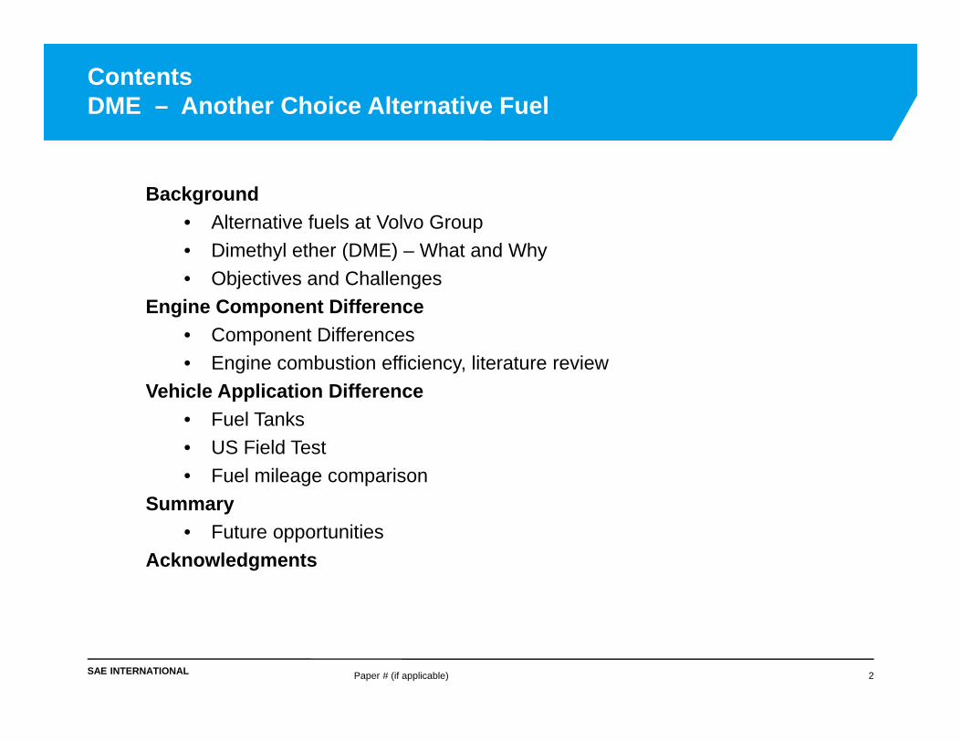
Background• Alternative fuels at Volvo Group• Dimethyl ether (DME) – What and Why• Objectives and Challenges
Engine Component Difference• Component Differences• Engine combustion efficiency, literature review
Vehicle Application Difference• Fuel Tanks• US Field Test• Fuel mileage comparison
Summary• Future opportunities
Acknowledgments
ContentsDME – Another Choice Alternative Fuel
Paper # (if applicable) 2
SAE INTERNATIONAL
• The Volvo Group products are almost exclusively driven by fossil diesel fuel
• The Volvo Group has for many years tried to increase the use of renewable fuels in viable commercial applications. None of the existing alternative fuels are optimal for all applications and all situations.
Prioritize high energy efficiency and Greenhouse Gas (GHG) reduction based on a well to wheel perspective.
Relate energy consumption and GHG impact to the workdone (g/ton-mile)
Formulate means and incentives with an internationalperspective
Clearly specify and standardize the properties of anyfuel or fuel blend
Advancing Fuel Alternatives at Volvo Group
Paper # (if applicable) 3
SAE INTERNATIONAL Paper # (if applicable) 4
What is DME (dimethyl ether)
DME uses• Household fuel (China)• Propellant in aerosol canister• Chemical feedstock
DME in diesel engine • Near zero soot and controlled NOx
DME is non-toxic, non-carcinogenic, and not a greenhouse gas
Properties • No sulfur• Heavier than air (behaves like LPG)• Boils at -11F • Liquid at ambient temperature under 5 bar pressure
Easy to store and transport (liquefies at low pressure)
Not cryogenic, negligible fugitive emissions, no tank venting
Clean, no soot combustion (no Particulate Filter required)
Non-toxic
10% carbon reduction in combustion balance compared to diesel
Low global warming potential (GWP = 0.3 @100 yr)
Synthesis from variety of bio-based feedstock
• High well-to-wheel efficiency for GHG emission
• Potential RINS opportunities
Synthesis from natural gas provides opportunity for single fuel from
NG/methanol pathway with diesel like efficiency
SAE INTERNATIONAL Paper # (if applicable) 8
Demo Project10 Trucks, 1.2 Million km
Feedstock: Black liquor from paper mill Output: 4 tons Bio-DME/day
Regional and local hauling Heavy-haul transport Local Delivery
SAE INTERNATIONAL
Objectives
• Minimize CO2 emissions, well to wheel• Meet diesel engine efficiency• Meet current diesel vehicle fuel economy• Limit the cost of vehicle adaptation
Challenges
• High fuel compressibility• Reduced energy content compared to diesel• Low fuel viscosity and lubricity• Seal and gasket material compatibility• Combustion development
Paper # (if applicable) 9
DME Fuel Objectives and ChallengesKnowledge from Swedish Field Test
SAE INTERNATIONAL
A DME Engine is a Compression-ignition Engine
Paper # (if applicable) 10
• The modified engine components consist of:• High pressure fuel pump, common rail, and fuel injectors.
• Moderate proprietary changes due to DME properties:• Higher fuel flow needed due to 67% energy content of diesel. • DME fuel also includes:
Lubricity improver for low fuel viscosityChemical properties seal & gasket materials
• DPF can be removed, however an oxi-cat is usedfor CO and HC reduction.
• EGR versus SCR is under investigation forNOx control.
No DPF necessary
SAE INTERNATIONAL Paper # (if applicable) 11
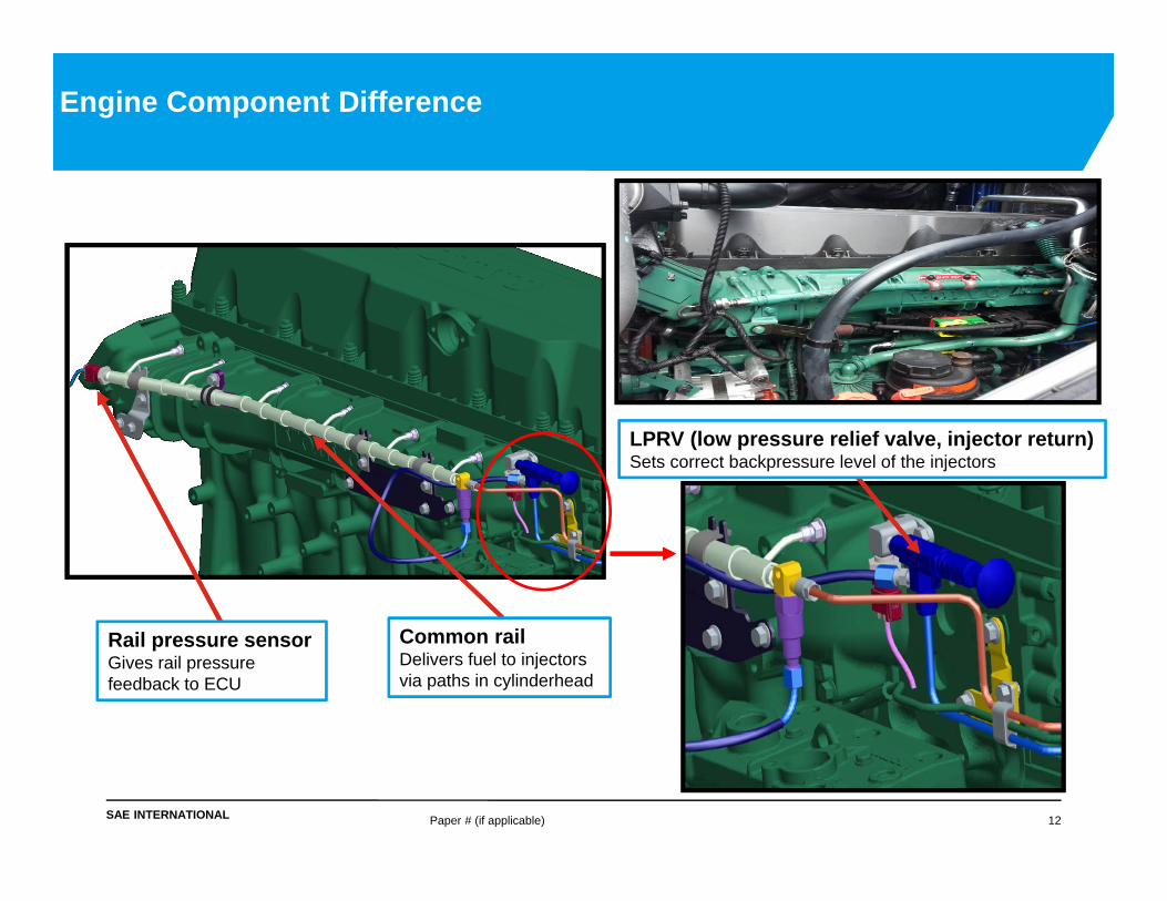
Engine Component Difference
”RPCV” (Rail Pressure Control Valve) alternatively ”IMV” – Inlet Metering Valve Performs feedback-based control of common rail pressure by variation of HP pump’s volumetric efficiency in real time
Injector return line
High pressure pump and injector return line to tanks
Supply line from tanks
High pressure feed line to rail
SAE INTERNATIONAL Paper # (if applicable) 12
Common railDelivers fuel to injectors via paths in cylinderhead
Rail pressure sensorGives rail pressure feedback to ECU
LPRV (low pressure relief valve, injector return) Sets correct backpressure level of the injectors
Engine Component Difference
SAE INTERNATIONAL Paper # (if applicable) 13
DME Combustion(DME Combustion in HD Diesel Engines, Dr. Salsing 2011, Chalmers University)
C60 load pt1.0 g/kwh Nox
• Using same combustion chamber h/w, distinct combustion differences are found between diesel and DME process.
• Distinct pre-mix burn notable for DME. Added slowing of diffusion burn indicates that additional mixing is needed for DME case.
• Below indicates potential improvement!
SAE INTERNATIONAL Paper # (if applicable) 14
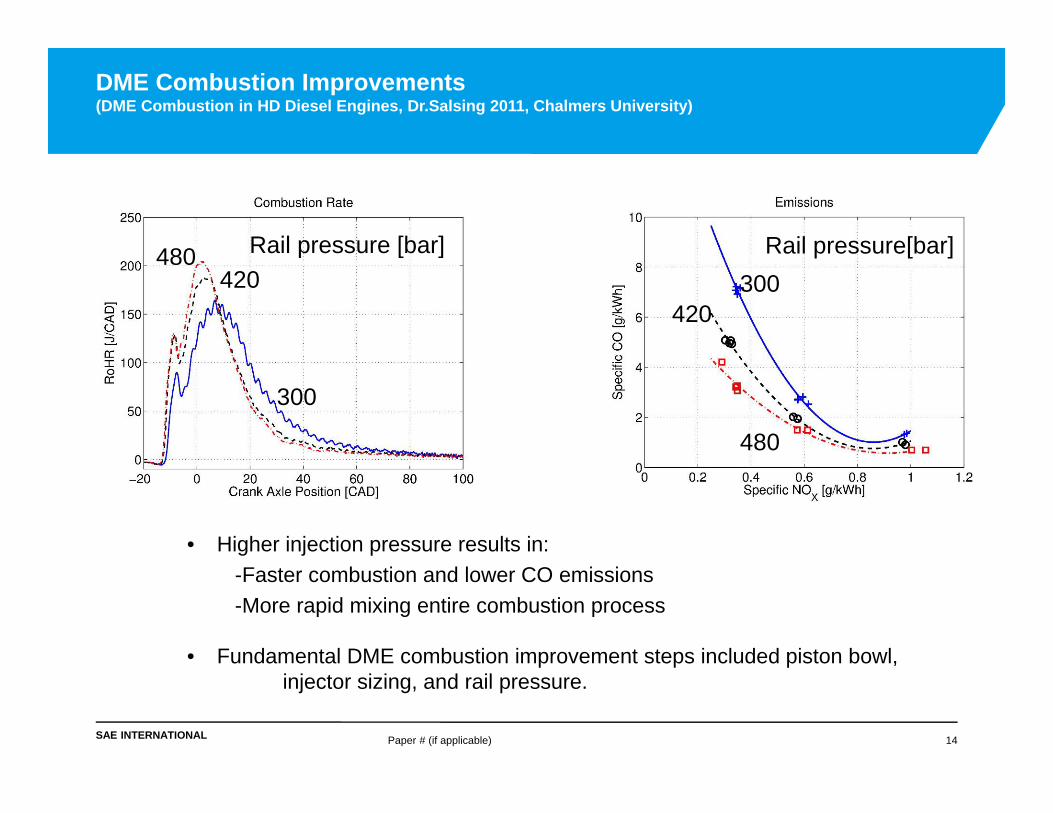
DME Combustion Improvements(DME Combustion in HD Diesel Engines, Dr.Salsing 2011, Chalmers University)
• Higher injection pressure results in:-Faster combustion and lower CO emissions-More rapid mixing entire combustion process
• Fundamental DME combustion improvement steps included piston bowl,injector sizing, and rail pressure.
480
480
420300
300
420Rail pressure [bar] Rail pressure[bar]
SAE INTERNATIONAL
Realized Fuel Efficiency Improvements(DME Combustion in HD Diesel Engines, Dr.Salsing 2011, Chalmers University)
Paper # (if applicable) 15
0.0
20.0
40.0
60.0
80.0
100.0
DME adapted piston Updated FIE Impoved nozzle High Injection pressure
Spec
ific
CO
com
pare
d to
ba
selin
e [%
]
Development Steps
Effects of Implemented Combustion Improvements for C60at NOx = 0.3 g/kWh
0.0
20.0
40.0
60.0
80.0
100.0
DME adapted piston Updated FIE Impoved nozzle High Injection pressure
BSF
C c
ompa
red
to
base
line
[%]
Development Steps
Effects of Implemented Combustion Improvements for C60at NOx = 0.3 g/kWh
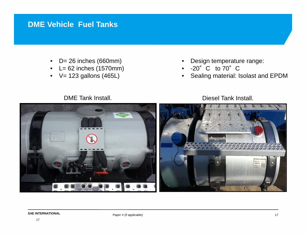
• Design temperature range:• -20°C to 70°C• Sealing material: Isolast and EPDM
DME Tank Install. Diesel Tank Install.
SAE INTERNATIONAL
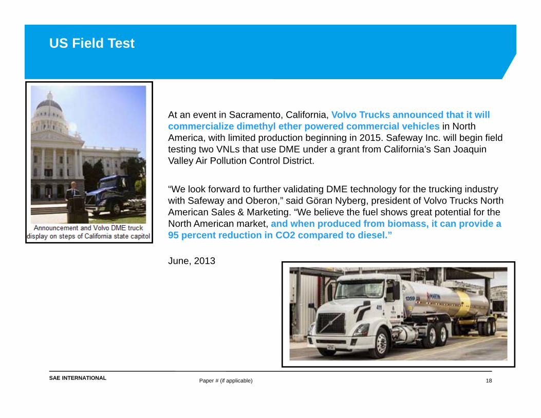
At an event in Sacramento, California, Volvo Trucks announced that it will commercialize dimethyl ether powered commercial vehicles in North America, with limited production beginning in 2015. Safeway Inc. will begin field testing two VNLs that use DME under a grant from California’s San Joaquin Valley Air Pollution Control District.
“We look forward to further validating DME technology for the trucking industry with Safeway and Oberon,” said Göran Nyberg, president of Volvo Trucks North American Sales & Marketing. “We believe the fuel shows great potential for the North American market, and when produced from biomass, it can provide a 95 percent reduction in CO2 compared to diesel.”
June, 2013
Paper # (if applicable) 18
US Field Test
SAE INTERNATIONAL
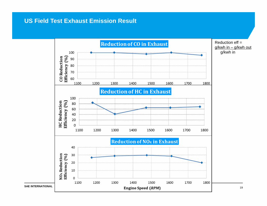
US Field Test Exhaust Emission Result
Paper # (if applicable) 19
Reduction eff =g/kwh in – g/kwh out
g/kwh in
SAE INTERNATIONAL
Chassis Vehicle Test at Penn State University
Paper # (if applicable) 20
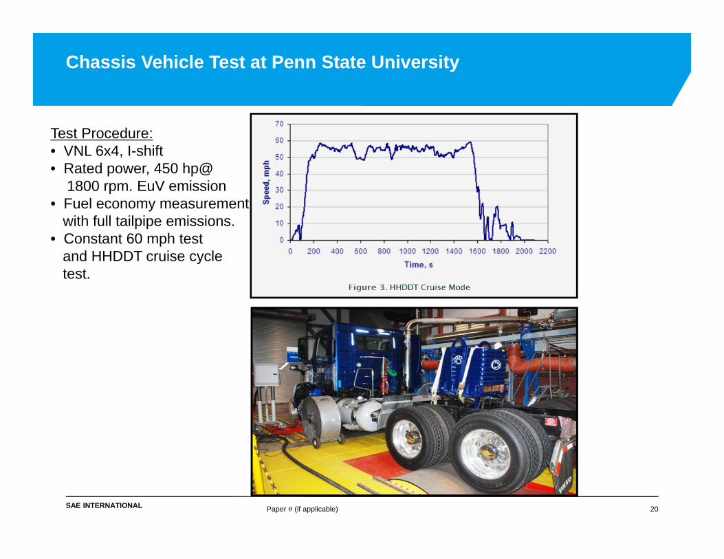
Test Procedure:• VNL 6x4, I-shift• Rated power, 450 hp@
1800 rpm. EuV emission• Fuel economy measurement
with full tailpipe emissions. • Constant 60 mph test
Energy-efficient Cost-effective Global potential for diesel
replacement in certain applications
Technology is demonstrated
Energy carrier for the future
SAE INTERNATIONAL
• Emission development and certification
• Component refinement and cost
• Reliability and durability demonstration
• Lube and fuel additive, continued development
• Combustion optimization towards 50% brake thermal efficiency
Paper # (if applicable) 23
Future Opportunities
SAE INTERNATIONAL
• Dr. Henrik Salsing, 2011 PhD “DME Combustion in Heavy Duty Diesel Engines”, Chalmers University
• Department of Energy, Kevin Stork
• Oak Ridge National Lab, James Szybist
• Penn State University, Dr. Suresh Iyer
• Volvo Team – Jan Arnell, Peter Gollunberg, Per Salomonsson, Tony Greszler, Bo Hammerlid, Rob Durling, Dale Hoover, Bryan Wu and many others.
• Prof A. Boehman, University of Michigan, Bhaskar Prabhakar, Penn State University, “Experimental Studies of High Efficiency Combustion with Fumigation of DME and Propane into Diesel Engine Intake Air”