NATIONAL TREASURY: REPUBLIC OF SOUTH AFRICA EMERGENCY MEDICAL SERVICES AMBULANCE CONVERSION TECHNICAL SPECIFICATION: PANEL VAN EMS 001/2018 OPTION 1 NOTE: 1. All materials used in the construction of the ambulance conversion are to meet SANAS/SABS standards 2. Conversion is to be approved by the relevant End-User Department after a “prototype” has been inspected and approved 3. Contractor must be an accredited ISO 9000 manufacturer 4. All conversion aspects related workmanship must carry at least 36 months warranty 5. Contractors to submit detailed project plan which should include midway inspection or at any time during production of each vehicle by the end user
Transcript
NATIONAL TREASURY: REPUBLIC OF SOUTH AFRICA
EMERGENCY MEDICAL SERVICES
AMBULANCE CONVERSION TECHNICAL SPECIFICATION: PANEL VAN
EMS 001/2018
OPTION 1 NOTE: 1. All materials used in the construction of the ambulance conversion are
to meet SANAS/SABS standards2. Conversion is to be approved by the relevant End-User Department after
a “prototype” has been inspected and approved3. Contractor must be an accredited ISO 9000 manufacturer4. All conversion aspects related workmanship must carry at least 36
months warranty5. Contractors to submit detailed project plan which should include
midway inspection or at any time during production of each vehicle by the end user
6. Sign off will depend on end user acceptance as per the prototype specification
List of abbreviations
LHS – Left Hand Side (passenger side)RHS – Right hand side (driver side)OEM – Original equipment manufacturer
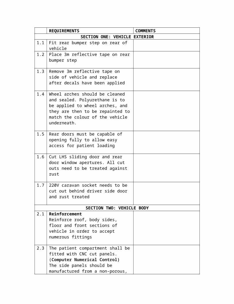
1.1 Fit rear bumper step on rear of vehicle1.2 Place 3m reflective tape on rear bumper
step
1.3 Remove 3m reflective tape on side of vehicle and replace after decals have been applied
1.4 Wheel arches should be cleaned and sealed. Polyurethane is to be applied to wheel arches, and they are then to be repainted to match the colour of the vehicle underneath.
1.5 Rear doors must be capable of opening fully to allow easy access for patient loading
1.6 Cut LHS sliding door and rear door window apertures. All cut outs need to be treated against rust
1.7 220V caravan socket needs to be cut out behind driver side door and rust treated
SECTION TWO: VEHICLE BODY2.1 Reinforcement
Reinforce roof, body sides, floor and front sections of vehicle in order to accept numerous fittings
2.3 The patient compartment shall be fitted with CNC cut panels. (Computer Numerical Control)The side panels should be manufactured from a non-porous, smooth, white high-gloss material. In addition the bulkhead/partition will be blue (#009fff hex colour) with decal in white as indicated in the attached picture. The ceiling and bulkhead partitioning should have a child friendly digital vinyl with a cloudy sky design (end user to confirm print prior to production).The panels should be washable and scratch resistant. The side walls should have a minimum thickness of 4mm. The panels must be secured with 8 x 20 mm dual location plugs or other suitable
securing method
2.4 Insulation (against heat and cold) needs to be placed behind all panels. Minimum requirement: Rockwool 233. Compliance with: EU14303,CINI 2.2.01 and ASTMC612 type IA and IB or equivalent
2.5 Where the interior panels intersect with the body or fittings, a polyurethane adhesive should be used to form a non-porous seal
2.6 Right Hand Side Body PanelWaist RailA custom manufactured waist rail is fitted to the top end of the lower cabinet on RHS of the vehicle. The waist rail is epoxy coated in yellow to match the finish of the interior panels and is constructed from 1.6mm mild steel
2.7 Gabbler RailThe 1st 750mm Gabbler rail must be fitted on the right hand side in-between the Overhead and lower cabinet in a central position. The 2nd 500mm Gabbler rail should fitted 150mm above shelf on right hand side adjacent to incubator. The Gabbler rail should be fastened securely to the side with 2 x 8mm stainless steel fasteners, and should be spaced away from the body side by a minimum of 40mmThe Gabbler rail should have a certified minimum load capacity of 10kg
2.8 Left Hand Side Body Panel2.9 Back Rest
A backrest is to be securely fitted above the Squad Bench. Length: 1750 mm (may require adjusting according to vehicle type), Height: 200 mm x 12mm ply, Depth: 60 mm. It should have a high density foam insert and be trimmed in a non-absorbent blue (colour code - #009fff) vinyl material
2.10
Side Panel Finishinga)The LHS and RHS panels, in between the rear edge of the front sliding door apertures
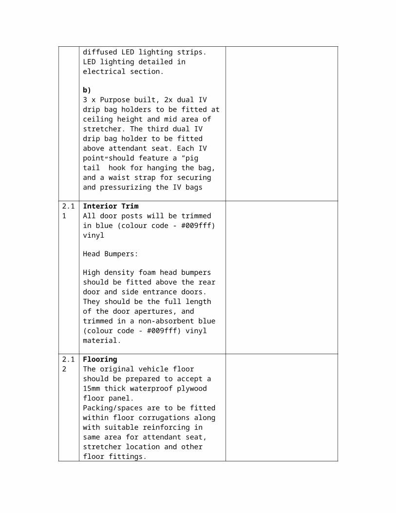
and the rear door aperture edge, should be fitted with a custom-manufactured section incorporating full-length diffused LED lighting strips.LED lighting detailed in electrical section.
b)3 x Purpose built, 2x dual IV drip bag holders to be fitted at ceiling height and mid area of stretcher. The third dual IV drip bag holder to be fitted above attendant seat. Each IV point should feature a “pig tail” hook for hanging the bag, and a waist strap for securing and pressurizing the IV bags
2.11
Interior TrimAll door posts will be trimmed in blue (colour code - #009fff) vinyl
Head Bumpers:
High density foam head bumpers should be fitted above the rear door and side entrance doors. They should be the full length of the door apertures, and trimmed in a non-absorbent blue (colour code - #009fff) vinyl material.
2.12
FlooringThe original vehicle floor should be prepared to accept a 15mm thick waterproof plywood floor panel.Packing/spaces are to be fitted within floor corrugations along with suitable reinforcing in same area for attendant seat, stretcher location and other floor fittings.
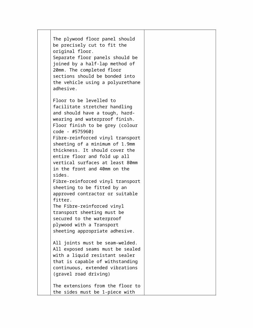
The plywood floor panel should be precisely cut to fit the original floor. Separate floor panels should be joined by a half-lap method of 20mm. The completed floor sections should be bonded into the vehicle using a polyurethane adhesive.
Floor to be levelled to facilitate stretcher handling and should have a tough, hard-wearing and waterproof finish.Floor finish to be grey (colour code - #575960) Fibre-reinforced vinyl transport sheeting of a minimum of 1.9mm thickness. It should
cover the entire floor and fold up all vertical surfaces at least 80mm in the front and 40mm on the sides. Fibre-reinforced vinyl transport sheeting to be fitted by an approved contractor or suitable fitter. The Fibre-reinforced vinyl transport sheeting must be secured to the waterproof plywood with a Transport sheeting appropriate adhesive.
All joints must be seam-welded. All exposed seams must be sealed with a liquid resistant sealer that is capable of withstanding continuous, extended vibrations (gravel road driving)
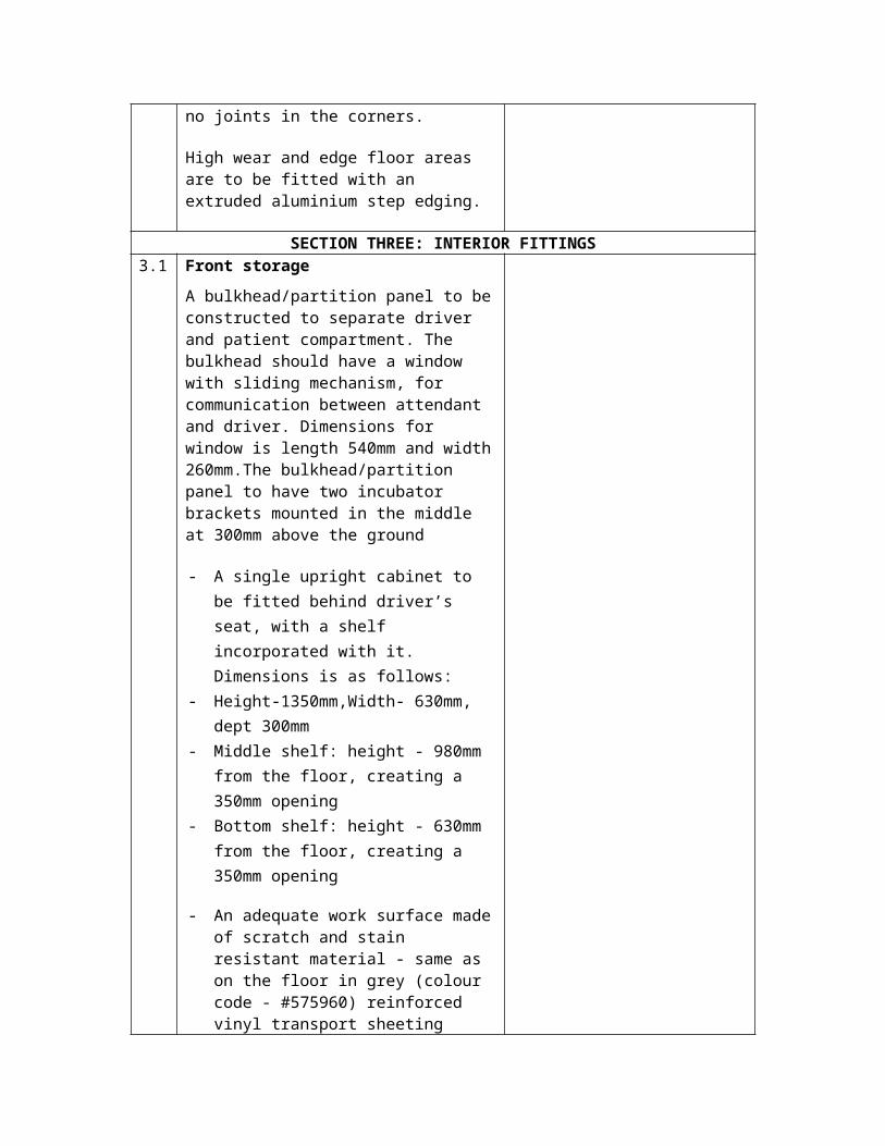
The extensions from the floor to the sides must be 1-piece with no joints in the corners.
High wear and edge floor areas are to be fitted with an extruded aluminium step edging.
SECTION THREE: INTERIOR FITTINGS3.1 Front storage
A bulkhead/partition panel to be constructed to separate driver and patient compartment. The bulkhead should have a window with sliding mechanism, for communication between attendant and driver. Dimensions for window is length 540mm and width 260mm.The bulkhead/partition panel to have two incubator brackets mounted in the middle at 300mm above the ground
- A single upright cabinet to be fitted behind driver’s seat, with a shelf incorporated with it. Dimensions is as follows:
- Height-1350mm,Width- 630mm, dept 300mm
- Middle shelf: height - 980mm from the floor, creating a 350mm opening
- Bottom shelf: height - 630mm from the floor, creating a 350mm opening
- An adequate work surface made of
scratch and stain resistant material - same as on the floor in grey (colour code - #575960) reinforced vinyl transport sheeting
- Secure strapping for ECG monitor or AED on the upper work surface, hook and spring buckle type
- The shelf shall not impede the safe storage of the portable incubator.
RHSThe RHS of the rear panel will have two cabinets, one overhead and one long cabinet.
The Overhead cabinet will have the following dimensions, with two sliding high tensile rigid Perspex sliding doors, for interior cabinet storage.
o Length 1510 mmo Height 340 mmo Width 300 mm
The long cabinet will have the following dimensions, with one sliding high tensile Perspex sliding door, for interior storage.
o Length 1990mm The long cabinet will have oxygen
storage for two large 10 litre cylinders, at the back facing rear door, with the turn screws for fastening.
The overhead and long cabinets should be joined by chrome tubing of 20 mm diameter at the proximal and distal ends
LHS
The LHS panel will have a Squad bench attached which would be angled to take into account space for patients and attendants.
The Squad bench will have the following
dimensions:o Length 2000 mmo Height 435 mm o Width
o Top 500 mmo Bottom 380 mm
The Squad bench will have oxygen storage at the front end.
The Squad bench must have a top opening with stay to hold lid open for storage space beneath seat. There must be 3 SABS approved inertia cap type seatbelts mounted on the squad bench. A 50 mm foam mattress is to be fixed to the lid. The lid is to be blue (colour code #009fff) and the rest of the squad bench white in colour.
All of the above should be conveniently accessible, and all fittings should be of industrial quality
The final design should be executed in conjunction with the end-user
3.2 Attendant Seat
A commuter 2000 single seat in non-absorbent blue (colour code - #009fff) vinyl material. Fitted securely with 4 x 10mm, 8.8 grade bolts with heavy duty galvanized fender washers and Nylock nuts to underside of vehicleSeat positioned in between shelf and compartment sufficient space for attendance legs should be considered within the available interior space
1 (one) SABS or E marked approved Inertia cap type belt is to be supplied and fitted onto the seat.
Located beneath attendant seat cushion should be a custom built bracket for secure retention of a standard sharps container. The sharps container should be readily accessible
A porta vac box holder should be mounted securely onto a slider mechanism that is attached to the bottom rear of attendant’s chair
3.3 Hand Rail ProvisionExtensive hand rails should be provided throughout the vehicle, securely fastened to predetermined, reinforced points within the module. Hand rails to be powder coated yellow (colour code f9f036)
The rear door and LHS sliding door should each have 2 x diagonal rails facing into the door aperture, each with a minimum length of 400mm. Each door rail should have a minimum of 2 x mounting points, each fastened with 8mm steel fasteners.
Hand rails should have the following features:- High visibility- Non-slip- Hand grip section 25mm minimum
diameter
3.4 Stretcher (Right Hand Side)a)Stretcher specification
1 x Four-castor self-loading ambulance stretcher with elevating head and fixed end will be fitted. Stretcher fitment as per OEM specificationsFitted with head section closest to the driver’s cabFitment should allow sufficient space at the head of the of the primary stretcher for an attendant seat
The stretcher should have as a minimum requirement the following features:
- Self-loading design- 3 x cross-strap restraints- Lightweight, rugged aluminium
construction- High visibility, powder coated frame- Seven height positions- Easy to use release handle design- One-hand release breakaway head
section with safety bar- One-hand release, fold down side rails- One-hand release, multi-positioning
backrest- Adequately sized wheels with sealed
caster and wheel bearings- Sealed bolster mattress- 2 x lap belts and 1 x four-point shoulder
restraint
b)Front stretcher fastening system should consist of:
A passive ankler type fastener located in a forward position. The ankler should be securely fastened to the floor of the vehicle in accordance with the stretcher manufacturer’s guidelines. The ankler bracket should provide directional stability and guidance when loading a stretcher.
Rear stretcher fastening system should consist of:
A quick-release, positively located fastener.When viewed from the rear, the rear fastener should be located on the right hand side of the stretcher
- The vehicle body should have been pre-provisioned during manufacture to accommodate the stretcher fasteners and provide reinforcement for the fastening system
- Stretcher and bracket positioning should be determined and installed in consultation with the end user according to OEM specifications
- All stretcher retaining brackets should be specific to and compatible with the selected stretcher, and should be of the same manufacturer as the stretcher
3.6 Equipment: provisioning for fitment and storage for equipment shall be made as per end-user defined requirements pertaining to shelving, cupboards and additional storage space (equipment shall be provided by the relevant end-user department for the RT4/2008ME Contract) aligned to the EMS Regulations 2017
3.7 Water Hand Washing UnitA mobile, collapsible water hand washing unit must be fitted. The unit should have a minimum capacity of 3 litres and provide at least 15 x 12 second hand washes per filling. The unit should provide self-containment of all waste water with the option of external drainage if needed.
The unit should be accompanied by a manual liquid soap dispenser or hand sanitizer dispenser. The dispenser should have a minimum volume of 1 litre. It should dispense 1,5 ml liquid per use and be refillable. An epoxy coated bracket needs to be made to hold dispenser bottle and be securely fastened to the bulkhead.
(Optional. The unit should be accompanied by a transparent paper towel holder and securely fastened to the bulkhead, to hold a minimum of 30 x KIMDRI regular folded hand towels or equivalent.)
Placement of hand washing unit:
Hand wash unit and its accessories are to be placed on to the bulkhead or RH panel depending on space and placed in such a way as to not interfere with the sliding door operations from the inside of the vehicle
3.8 1 x 1kg or 1 x 1.5kg SABS approved, fire extinguisher with steel retaining bracket and retaining “R” clip to be fitted in the driver cab – placement in consultation with end user
3.9 A slim line 12v Air-conditioning unit should be fitted on the ceiling in the rear of the vehicle above the rear door, and should function with the vehicle’s existing Air-conditioning system
3.1 Thermometer to be fitted to the patient
0 compartment in such a way that it can measure ambient temperature of the patient compartment. Fitment to be decided after consultation with end-user
SECTION FOUR: OXYGEN4.1 2x portable 2 litre cylinders to be housed in
a chute at the front end of Squad bench with dimensions:-
Length 580 mm Width 147 mm Angle/slope 4 degrees
2 x large 10 litre cylinders to be housed in chute in long cabinet with dimensions:-
Length 710 mm Width 147 mm Angle/slope 4 degrees
4.2 A bullnose oxygen regulator with DISS is to be supplied and fitted. The regulator is to be piped via certified oxygen piping from this compartment into three (3x) wall mounted eminence oxygen outlets within the vehicle. (Located upper LHS by sliding door and RHS in line with LHS) and above shelf at incubator position.The wall mounted flow meters shall be complete with oxygen ports and oxygen dial-stop meters with flow rate parameters ranging from 1 to 25 litres with surface mounted tubing will be supplied. Minimum of 3 (three)
4.3 The oxygen system should be certified, and a test certificate should be issued with the vehicle
4.4 Oxygen pipe should have the following requirements or equivalent :
fibres used at the optimum braid angle of 54° 44’ (54.73°) creates an effective and balanced pressure hose.
- Exceptional performance and renowned
for reliability.- Conforms to BS EN ISO 5359:2008
meeting the current criteria for use with low pressure medical gases
- Cadmium and silicone free.- Carefully selected materials conforming
to BS ISO 2878:2005 Electrical Conductivity
- Medical colour standards- Striped hoses for mixed gases- Resistant to a wide range of chemicals
4.5 All pipes connections must be clamped with OERTIKA type clamps or equivalent
NOTE: Oxygen bottles and any oxygen equipment other than stated would be end-user supplied.
SECTION FIVE: WINDOWS5.1 One bonded window on the left of the
patient compartment shall be provided within the sliding door apertures. The window shall be fully sliding and shatterproof safety glass. The size of the window shall be as per the OEM specifications. The upper two thirds should be double sliding, and the lower one third fixed. The bottom two thirds should be frosted and the top third tinted to ensure patient privacy All windows to have interior locking devices
5.2 Both rear doors to be fitted with individual fixed glasses. Glasses to conform to shape and radius of rear doors. Fixed rear windows and the window in the left side sliding door of the compartment must be two thirds frosted (lower) and one third tinted (upper) to ensure privacy
5.3 All windows to be shatterproof safety glass
5.4 The patient compartment shall be completely dust proof
5.5 Bonded sliding/fixed windows as specified above, must be freely obtainable for replacement
5.6 The driver and passenger door windows
shall be fitted with Anti Smash And Grab 100mic clear Safety Film or equivalent
SECTION SIX: ELECTRICAL CONFIGURATION6.1 220V AC Power
a)A 12V DC to 220V AC; 1500 - 2000W Pure Sine Wave inverter must be fitted
b)The inverter shall incorporate a multi stage intelligent battery charger capable of 35A at 12V.Minimum of 1500W Power inverter – 12 volt to 220 volt ACPure Sine Wave inverterOutput frequency: 50/60Hz switch selectionsRated power: 3000 wattDC input voltage: 12 voltInput and output fully isolated designPower saving mode to conserve energyHigh efficiency 89-94%Driving highly reactive and capacitive loads at start momentTri-colour indicators show input voltage and output load levelLoading controlled cooling fanAdvanced microprocessor andProtection for:
- Input low voltage- Overload- Short circuit- Low battery alarm- Input over voltage- Over temperature
c)The inverter/charger shall conform to EN 60335-1 safety standards (minimum) and 2004/104/EC automotive EMC directive
d)A remote On/Off switch for the inverter is to be located within the patient compartment. An indicator light is to be provisioned to indicate the presence of 220V power from the inverter.e)220V AC is to be distributed via a
distribution board to 3 outlets.The distribution board shall be fitted with an earth leakage circuit breaker and a suitably rated overload protection breaker (6A max).Each outlet must contain a standard South African 3 pin 16A (Type D), a Euro (Type J) and a Schuko (Type F) socket. Each outlet to have its own on/off switch
f)An auto eject electrical input system is to be provisioned on the outside of the vehicle to allow connection to grid (shore) power.Upon sensing engine start, plug ejects from receptacle and away from vehicle path.After eject, weatherproof cover snaps into position over inlet.An indicator light is to be fitted inside the power inlet to indicate the presence of grid power
g)The power inlet will auto-eject the power supply cable when the vehicle’s ignition switch is turned to the IGN position
h)A 2.5mm² wire x 20 meter extension lead with matching coupler and real is to be provided
6.2 12V DC Powera)A second, auxiliary battery (12V) is to be fitted. The battery must be a lead-acid, deep cycle battery with a minimum rating of 80A/h. The second battery is to be connected to the vehicle’s main battery via an automatic isolator/combiner
b)The isolator/combiner must engage when either one of the batteries’ voltage exceeds 13.1V and disengage when combined battery voltage is below 12.8V. The Isolator/combiner is to have a continuous current rating of 120A (minimum). Both main and auxiliary side of the isolator/combiner to be fused (100A).The auxiliary battery 12V DC is to be
distributed via a distribution board
c)Two 12V DC Hella type sockets are to be fitted in the patient compartment – one left and one right in the centre
d)The Water Hand Washing Unit must switch on/off with the vehicle’s ignition switch but power must be provided by the auxiliary battery
f)A 6 way blade fuse panel is to be fitted near the auxiliary battery. This fuse holder will be used for third party connections. The fuse panel must make provision for:
- 2-Way radio – 2A- eFuel – 5A- Vehicle tracking device – 5A- MI System – 5A- 2 x Spare
6.3 MI SystemAuxiliary battery via a battery protector.
The battery protector must disconnect power if the battery voltage drops below 12.2V
The battery protector must reconnect power if the battery voltage rises above 13.1V
The battery protector shall have a continuous current rating of 5A (minimum)
A distribution board shall be provided and fitted in a suitable place within the patient compartment
All electrical wiring shall be a minimum of 2.5 mm diameter
All wiring shall be covered with acceptable PVC/plastic covering
All electrical circuits for accessories must be routed through suitable fuses
6.4 Emergency Lightinga)8-LED (2 rows of 4) Red Clusters to be used throughout except where otherwise noted.Cluster rows must be individually controlled and dual colour optional (e.g. red/white or red/amber)
b)8-LED clusters generation4 or newer to be used in light bar.Light bar above windscreen to have five forward facing clusters. One cluster at 45° and one cluster at 90° to be fitted on the left and right of the light bar.LED Spot lights to be fitted on the R/H and L/H sides of light bar.Please refer to 2.1 for mounting of bar
c)On each side of the vehicle, one cluster to be positioned top rear and top middle. The end user may request that the middle cluster be Amber or Red
d)On the rear door(s), one cluster at top left, top right, waist high left and waist high right.If, by opening the rear door(s), the top clusters are obscured, additional clusters must be fitted inside the door recess –one left and one right (vehicle dependent)
e)Two clusters to be fitted in the radiator grill (left and right). These clusters to be red/white. Two 4-LED clusters may be substituted for a single 8-LED cluster where the mounting of an 8-LED cluster is impractical
f)A single, high intensity, dome style, flashing LED (red) to be fitted on each of the 4 corners of the vehicle at or near bumper height. These to be positioned for maximum protection from accidental damage
g)
A two channel flasher unit is to be used to flash all clusters. Refer to diagram 1.2 for channel configuration
h) Single colour clusters must flash both rows simultaneously. Dual colour cluster must flash each colour alternately
6.5 Interior Lightinga) All interior lighting should be rigid LED strip lights, using 50/50 SMT Cool White LED at 30 LED per meter unless otherwise noted
b)All LED lights should be mounted behind a light diffuser lens
c)Lights should be independently switched for the LHS and RHS and clearly marked. Interior light switches to be located on the bulkhead near the left hand sliding door
d)Patient compartment ceiling lights should run the full length of the vehicle on both sides
e)The step inside the sliding door is to be lit by LED strip lighting which should switch on when the sliding door is opened and switch off when the sliding door is closed (using existing door switches)
f)A master cut off switch shall be placed in the cab to allow the driver to switch lights off when needed
g) A LED 27 watt loading light should be fitted inside at the right hand upper corner of the rear door aperture. Switch should be easily accessible from the rear
6.6 Exterior Lighting The driver and passenger door to be fitted
with red LED strip light along the trailing edge of the door.20cm per strip; 6 x 50/50 SMT LED per strip.Strip light to switch on when door is opened and off when door is closed (using existing door switches)
6.7 SirenOutput 200W with 1 speaker (placed in engine compartment, close as possible to grill and facing outward in the direction of the grill)
- Wail, yelp & phaser tones.- Dual tone (stereo) - one tone through
speaker.- Touch control panel.- Horn ring control (press twice to activate
response mode - lights & siren on – press again to change tone; press twice to silence siren; press once to switch lights off
6.8 Park Distance controlPark distance control to be fitted, with 4 x bumper mount sensors to detect the proximity of objects up to 1.5m away.
Features required:- Slow beeps are sounded when an
object is detected with the 1.5 - 0.9m range
- Fast beeps are sounded when an object is detected with the 0.9 – 0.45m range
- A continuous tone is sounded if an object is detected with 0.45m
- Auto-on when reverse gear is selected
Rear CameraA rear facing camera and LED spot light shall be mounted on the rear above the doors. The screen for the camera shall be incorporated into the dash.Loading lights needs to be incorporated with the camera while in motion. A buzzer
with a timer needs to be installed to notify the driver of activation while driving
Central LockingAll doors must be centrally lockable from both inside the driving cab and the patient compartment. Patient compartment switch to be positioned with end user consultation
SECTION SEVEN: PAINTING AND MARKING7.1 Yellow and green segmented Battenberg
style, high visibility markings made from reflective material on the LHS and RHS of vehicle
7.2 Star of life on LHS and RHS with Protekta Glaze clear coat for added scratch resistance and UV protection.
7.3 To be indicated on the LHS and RHS respectively:
1. The respective “Province” 2. Emergency Medical Services3. Fleet number
7.4 Telephone icon with ‘112’ on LHS and RHS
7.5 SA flag depicted on LHS and RHS
7.6 Provincial Coat of Arms to be displayed on both cab doors. With Protekta Glaze clear coat for added scratch resistance and UV protection
7.7 Star of life on Bonnet with Protekta Glaze clear coat for added scratch resistance and UV protection.
7.8 The word ‘Ambulance’ to be displayed on bonnet, with a reflective strip below. Size: 600mm x 150mm as well as on the rear of vehicle
7.9 The word ‘Diesel/Petrol’ (vehicle dependent) to be displayed below the fuel cap
7.10
High visibility segmented chevron patterned reflective marking to cover the entire back panel of the vehicle. Vinyl specification: Orange and lime green 3M
7.11 Large call sign to be displayed on vehicle
roof (approximately 785 x 355mm)
7.12
Printed on 3M IJ 680-10 cast reflective digital print vinyl – white overlamed.
7.13
The words “No Smoking” decal to be stuck on the inside where visible (or alternatively the international “No Smoking” pictograph sign may be applied). This will also be required in the drivers compartment
7.14
All vehicles will be marked as per provincial end-user requirements in 3M Vehicle reflective materials as per the national branding specifications
7.15
The words “Emergency Exit” to be displayed on rear and sliding doors
SECTION EIGHT: BODY REFURBISHMENT & LIFESPAN8.1 The ambulance conversion components
must be manufactured in such a manner that they provide two lifespans of approximately 4 years each.After 4 years of normal service life, selected components should have the ability to be removed from the base vehicle and undergo refurbishment in preparation for fitting into a new vehicle, so as to provide an additional 4 years of service after refurbishment
8.2 The refurbishment of these components should result in a minimum of a 20% saving against the cost of a brand new ambulance conversion, excluding equipment and base vehicle
SECTION NINE: ADDITIONAL REQUIREMENTS9.1 A good calibre (high quality) wrap around
Bull bar shall be fitted directly to the chassis of the vehicle. OEM approved and fitted
9.2 1 x 1kg or 1 x 1.5kg SABS approved, fire extinguisher with steel retaining bracket and retaining “R” clip to be fitted in the driver compartment – placement in consultation with end user
9.3 Vehicle must include the supply and installation of an UV light effective against micro-organisms which is equivalent to the Sani 18. UV lamp capable of emitting UV-C light at a wavelength of 253.7/254 nm and should be 12-24 Volt.
The unit must have a twelve month guarantee and a second year service plan.
9.4 Air-Conditioning system for the patient compartment of vehicle to be supplied, installed, fitted and included in the final pricing schedule. Must carry a minimum of a 3-year warranty
9.5 All instruments, gauges and switches shall be clearly marked as to their use. Dymo stencilling shall not be accepted
SECTION TEN: DRAWINGSThe following detailed drawings shall be included in the Bid submission.Failing to do so will result in rejection of Bid. 10.1
Side view of Ambulance- Total Length, height, and loading height. - Window position and dimension. - Sign writing and stripping. - Compartment mounting to chassis.
Body construction showing material used and dimension
10.2
Rear view of Ambulance- Door dimension - Interior dimensions- Plan of outlay of equipment - Rear view showing placement of light
units - Detail of attachments to hold drip bottles
and stretcher anchoring devices- Detailed drawing of body construction
showing material used and dimensions- Diagram of battery linking (management
system)
10.3
Front view of AmbulanceFront view indicating light unit placement, type and sign writing
10.4
Top view of patient compartment- Plan indicating the compartment layout
from a top view.
Complete diagram indicating the electrical management system
10.5
Spare wheel mounting
10.6
Full vehicle wiring diagram
ADDITIONAL ACCESORIES
1. Flashing red lights connected to the back door of the ambulance2. Separate switches for lights inside passenger compartment3. Optional bull bar to meet the following requirements – comply with vehicle
safety features – should be OEM approved, should have the option of not reducing the ground clearance of the vehicle and additional lights (end user specified).
4. Inverter should be standard (pure sine wave) 1500 - 2000 Watt. Modifications to inverter will not be accepted
1. HOMOLOGATION & CERTIFICATION
a) The conversion must be supplied complete with Natis documentation and certification including:
- A Certified Weight Bridge Certificate stating the Total Tare Mass of the Converted Vehicle.
- All Ambulance Conversion Homologation Documentation.- A Manufacturer’s/ End Manufacturers Certificate Stating: Body conversion Number
AND NRCS Natis Number applicable to the particular conversion.- Any other Information related to the Conversion.- Must stipulate the amount of seated patients the vehicle may carry post conversion
b) The unit should comply with all relative legislation pertaining to the conversion.
2. ADDITIONAL CONDITIONS WITH PENALTIES
a) The successful must construct a prototype within 5 weeks for inspection and testing by a representative of the Department of Transport and end user for
approval and/or possible alterations, before constructing any subsequent units.
b) The prototype unit, when accepted, shall serve as a standard for the construction of further units.
c) The End-User reserves the right of inspection of the prototype, as well as of any other units, at any stage of their construction.
d) A representative of the bid company shall be present during the inspections to record all faults and decisions for future reference
The End-User Department is at liberty to reject and return equipment supplied should there be any deviation from the information given in the above schedule or elsewhere in this bid and where relevant should there be any difference between masses given in the schedule and the actual mass measuring bridge figures
The completed vehicle must be handed over to the End-User Department with the following documentation.
a) Certified weigh bridge certificate stating the total Tare massb) Relevant body homologation documentationc) Manufacture certificate with body number, NATIS number and conversion mass
All Bidders must be registered as a Manufacturer, Builder and Importer of motor vehicles as per National Road Traffic Act 1996 Act 93 section 5
The installer of the Oxygen piping must issue a Test and compliance certificate.
GUARANTEE
The complete body must be guaranteed for at least four (4) years against rust to the body work or paint defects; fair wear and tear excluded.
All the electrical equipment including the warning lights and sirens must be guaranteed for 36 months.
DELIVERY
Bidders must specify dispatch dates clearly in terms of lead time, rate of dispatch and completion of contract. DEVIATIONS
Electrical conversion – Deviations will not be accepted. Deviations will result in penalties and will result in end-user not accepting the vehicle and the converter reported to the OEM with the view of blacklisting.
Mechanical conversion – Deviations will not be accepted. Deviations will result in penalties and will result in end-user not accepting the vehicle and the converter reported to the OEM with the view of blacklisting.
Structural conversion – Deviations will not be accepted. Deviations will result in penalties and will result in end-user not accepting the vehicle and the converter reported to the OEM with the view of blacklisting.
Branding - Deviations will not be accepted. Deviations will result in penalties and will result in end-user not accepting the vehicle and the converter reported to the OEM with the view of blacklisting.