EN 1995-1-2 (2004) (English): Eurocode 5: Design of timber structures - Part 1-2: General - Structural fire design [Authority: The European Union Per Regulation 305/2011, Directive 98/34/EC, Directive 2004/18/EC]
Transcript
The European Union
In order to promote public education and public safety, equal justice for all, a better informed citizenry, the rule of law, world trade and world peace, this legal document is hereby made available on a noncommercial basis, as it is the right of all humans to know and speak the laws that govern them.
≠ EDICT OF GOVERNMENT ±
EN 1995-1-2 (2004) (English): Eurocode 5: Design of timberstructures - Part 1-2: General - Structural fire design[Authority: The European Union Per Regulation 305/2011,Directive 98/34/EC, Directive 2004/18/EC]
EUROPEAN STANDARD EN 1995-1-2
NORME EUROPEENNE
EUROpAISCHE NORM November 2004
ICS 91.010.30; 13.220.50; 91.080.20 Incorporating corrigenda June 2006 and March 2009 Supersedes ENV 1995-1-2: 1994
English version
Eurocode 5: Design of timber structures - Part 1-2: General -Structural fire design
Eurocode 5: Conception et Calcul des structures en boisPart 1-2: GEmeralites - Calcul des structures au feu
Eurocode 5: Entwurf, Berechnung und Bemessung von Holzbauten - Teil1-2: Allgemeine Regeln - Bemessung fOr
den Brandfall
This European Standard was approved by CEN on 16 April 2004.
CEN members are bound to comply with the CEI\jfCEI\JELEC Internal Regulations which stipulate the conditions for giving this European Standard the status of a national standard without any alteration. Up-to-date lists and bibliographical references concerning such national standards may be obtained on application to the Central Secretariat or to any CEN member.
This European Standard exists in three official versions (English, French, German). A version in other language made by translation under the responsibility of a CEN member into its own language and notified to the Central Se!:::reltariat has the same status as the official versions.
CEN members are the national standards bodies of Austria, Belgium, Cyprus, Czech Republic, Denmark, Estonia, Finland, France, Germany, Greece, Hungary, Iceland, Ireland, Italy, Latvia, Lithuania, Luxembourg, Malta, Netherlands, Norway, Poland, Portugal, Slovakia, Slovenia, Spain, Sweden, Switzerland and United Kingdom.
EUROPEAN COMMITTEE FOR STANDARDIZATION COMlTE EUROPEEN DE NORMALISATION EUROrAISCHES KOMlTEE FOR NORMUNG
Management Centre: rue de Stassart, 36 B-1050 Brussels
2004 CEN All rights of exploitation in any form and by any means reserved worldwide for CEN national Members.
Ref. No. EN 1995-1-2:2004: E
BS EN 1995-1-2:2004 EN 1995-1-2:2004 (E)
Contents
Foreword 4 Background of the Eurocode programme 4 Status and field of application of Eurocodes 5 National Standards implementing Eurocodes 5 Links between Eurocodes and harmonised technical specifications (ENs and ETAs) for products 6 Additional information specific to EN 1995-1-2 6 National annex for EN 1995-1-2 7
Section 1 General 9 1.1 Scope 9
1.1.1 Scope of Eurocode 5 9 1 .1 .2 Scope of EN 1995-1-2 9
1.2 Normative references 10 1.3 Assumptions 10 1.4 Distinction between principles and application rules 10 1.5 Terms and definitions 11 1.6 Symbols 11
Section 2 Basis of design 14 2.1 Requirements 14
2.1.1 Basic requirements 14 2.1.2 Nominal fire exposure 14 2.1.3 Parametric fire exposure 14
2.2 Actions 15 2.3 Design values of material properties and resistances 15 2.4 Verification methods 16
2.4.1 General 16 2.4.2 Member analysis 17 2.4.3 Analysis of parts of the structure 18 2.4.4 Global structural analysis 19
Section 3 Material properties 20 3.1 General 20 3.2 Mechanical properties 20 3.3 Thermal properties 20 3.4 Charring depth 20
3.4.1 General 20 3.4.2 Surfaces unprotected throughout the time of fire exposure 21 3.4.3 Surfaces of beams and columns initially protected from fire exposure 23
3.4.3.1 General 23 3.4.3.2 Charring rates 26 3.4.3.3 Start of charring 27 3.4.3.4 Failure times of fire protective claddings 28
4.3 Simplified rules for analysis of structural members and components 32 4.3.1 General 32 4.3.2 Beams 32 4.3.3 Columns 33 4.3.4 Mechanically jointed members 33 4.3.5 Bracings 34
4.4 Advanced calculation methods 34 Section 5 Design procedures for wall and floor assemblies 35
2
BS EN 1995-1-2:2004 EN 1995-1-2:2004 (E)
5.1 General 35 5.2 Analysis of load-bearing function 35 5.3 Analysis of separating function 35
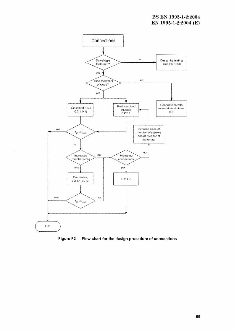
Section 6 Connections 36 6.1 General 36 6.2 Connections with side members of wood 36
7.1 Walls and floors 43 7.1.1 Dimensions and spacings 43 7.1.2 Detailing of panel connections 43 7.1.3 Insulation 43
7.2 Other elements 43 Annex A (Informative) Parametric fire exposure 45
A1 General 45 A2 Charring rates and charring depths 45 A3 Mechanical resistance of members in edgewise bending 47
Annex B (informative) Advanced calculation methods 48 B1 General 48 B2 Thermal properties 48 B3 Mechanical properties 50
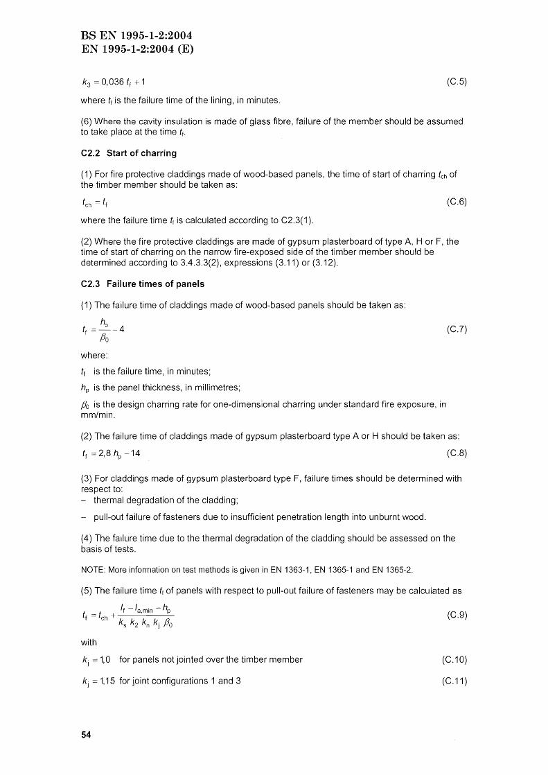
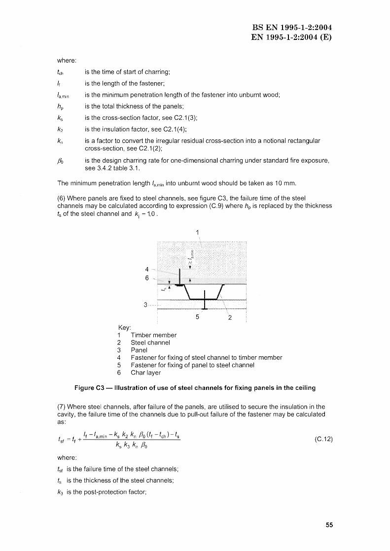
Annex C (Informative) Load-bearing floor joists and wall studs in assemblies whose cavities are completely filled with insulation 52
C1 General 52 C2 Residual cross-section 52
C2.1 Charring rates 52 C2.2 Start of charring 54 C2.3 Failure times of panels 54
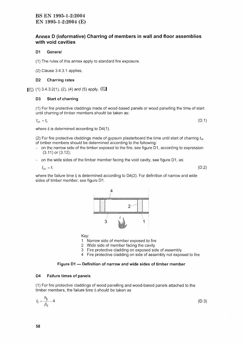
C3 Reduction of strength and stiffness parameters 56 Annex 0 (informative) Charring of members in wall and floor assemblies with void cavities 58
D1 General 58 02 Charring rates 58 D3 Start of charring 58 04 Failure times of panels 58
Annex E (informative) Analysis of the separating function of wall and floor assemblies 60 E 1 General 60 E2 Simplified method for the analysis of insulation 60
E2.1 General 60 E2.2 Basic insulation values 61 E2.3 Position coefficients 62 E2.4 Effect of joints 62
Annex F (informative) Guidance for users of this Eurocode Part 68
3
BS EN 1995-1-2:2004 EN 1995-1-2:2004 (E)
Foreword
This European Standard EN 1995-1-2 has been prepared by Technical Committee CEN/TC250 "Structural Eurocodes", the Secretariat of which is held by BSI.
This European Standard shall be given the status of a National Standard, either by publication of an identical text or by endorsement, at the latest by May 2005, and conflicting national standards shall be withdrawn at the latest by March 2010.
This European Standard supersedes ENV 1995-1-2:1994.
CENITC250 is responsible for all Structural Eurocodes.
According to the CEN/CENELEC Internal Regulations, the national standards organizations of the following countries are bound to implement this European Standard: Austria, Belgium, Cyprus, Czech Republic, Denmark, Estonia, Finland, France, Germany, Greece, Hungary, Iceland, Ireland, Italy, Latvia, Lithuania, Luxemburg, Malta, Netherlands, Norway, Poland, Portugal, Slovakia, Slovenia, Spain, Sweden, Switzerland and United Kingdom.
Background of the Eurocode programme
In 1975, the Commission of the European Community decided on an action programme in the field of construction, based on article 95 of the Treaty. The objective of the programme was the elimination of technical obstacles to trade and the harmonisation of technical specifications.
Within this action programme, the Commission took the initiative to establish a set of harmonised technical rules for the design of construction works which, in a first stage, would serve as an alternative to the national rules in force in the Member States and, ultimately, would replace them.
For fifteen years, the Commission, with the help of a Steering Committee with Representatives of Member States, conducted the development of the Eurocodes programme, which led to the first generation of European codes in the 1980's.
In 1989, the Commission and the Member States of the EU and EFTA decided, on the basis of an agreement1 between the Commission and CEN, to transfer the preparation and the publication of the Eurocodes to the CEN through a series of Mandates, in order to provide them with a future status of European Standard (EN). This links de facto the Eurocodes with the provisions of all the Council's Directives and/or Commission's Decisions dealing with European standards (e.g. the Council Directive 89/106/EEC on construction products - CPD and Council Directives 93/37/EEC, 92/50/EEC and 89/440/EEC on public works and services and equivalent EFTA Directives initiated in pursuit of setting up the internal market).
The Structural Eurocode programme comprises the following standards generally consisting of a number of Parts:
EN 1990 EN 1991 EN 1992 EI\J 1993 EN 1994 EN 1995 EN 1996 EI\J 1997
Basis of Structural Design Actions on structu res Design of concrete structures Design of steel structures Design of composite steel and concrete structures Design of timber structures Design of masonry structures Geotechnical design
1 Agreement between the Commission of the European Communities and the European Committee for Standardisation (CEN) concerning the work on EUROCODES for the design of building and civil engineering works (BC/CEN/03/89).
4
BS EN 1995-1-2:2004 EN 1995-1-2:2004 (E)
EN 1998 EN 1999
Eurocode 8: Eurocode 9:
Design of structures for earthquake resistance Design of aluminium structures
Eurocode standards recognise the responsibility of regulatory authorities in each Member State and have safeguarded their right to determine values related to regulatory safety matters at national level where these continue to vary from State to State.
Status and field of application of Eurocodes
The Member States of the EU and EFTA recognise that EUROCODES serve as reference documents for the following purposes:
as a means to prove compliance of building and civil engineering works with the essential requirements of Council Directive 89/106/EEC. particularly Essential Requirement N°1 -Mechanical resistance and stability - and Essential Requirement N°2 - Safety in case of fire;
as a basis for specifying contracts for construction works and related engineering services; - as a framework for drawing up harmonised technical specifications for construction products
(ENs and ETAs).
The Eurocodes, as far as they concern the construction works themselves, have a direct relationship with the Interpretative Documents2 referred to in Article 12 of the CPO, although they are of a different nature from harmonised product standards3
. Tllerefore, technical aspects arising from the Eurocodes work need to be adequately considered by CEN Technical Committees and/or EOTA Working Groups working on product standards with a view to achieving full compatibility of these technical specifications with the Eurocodes.
The Eurocode standards provide common structural design rules for everyday use for the design of whole structures and component products of both a traditional and an innovative nature. Unusual forms of construction or design conditions are not specifically covered and additional expert consideration will be required by the designer in such cases.
National Standards implementing Eurocodes
The National Standards implementing Eurocodes will comprise the full text of the Eurocode (including any annexes), as published by CEN, which may be preceded by a National title page and National Foreword, and may be followed by a National Annex.
The National annex may only contain information on those parameters which are left open in the Eurocode for national choice, known as Nationally Determined Parameters, to be used for the design of buildings and civil engineering works to be constructed in the country concerned, i.e.:
values and/or classes where alternatives are given in the Eurocode, - values to be used where a symbol only is given in the Eurocode, - country specific data (geographical. climatic, etc.). e.g. snow map, - the procedure to be used where alternative procedures are given in the Eurocode. It may also contain
2 According to Art. 3.3 of the CPO, the essential requirements (ERs) shall be given concrete form in interpretative documents for the creation of the necessary links between the essential requirements and the mandates for harmonised ENs and ETAGs/ETAs.
3 According to Art. 12 of the CPD the interpretative documents shall: give concrete form to the essential requirements by harmonising the terminology and the technical bases and indicating classes or levels for each requirement where necessary; indicate methods of correlating these classes or levels of requirement with the technical specifications, e.g. methods of calculation and of proof, technical rules for project design, etc.; serve as a reference for the establishment of harmonised standards and guidelines for European technical approvals. The Eurocodes, de facto, playa similar role in the field of the ER 1 and a part of ER 2.
5
BS EN 1995-1-2:2004 EN 1995-1-2:2004 (E)
- decisions on the application of informative annexes, - references to non-contradictory complementary information to assist the user to apply the
Eurocode.
Links between Eurocodes and harmonised technical specifications (ENs and ETAs) for products
There is a need for consistency between the harmonised technical specifications for construction products and the technical rules for works4. Furthermore, all the information accompanying the CE Marking of the construction products which refer to Eurocodes shall clearly mention which Nationally Determined Parameters have been taken into account.
Additional information specific to EN 1995-1-2
EN 1995-1-2 describes the principles, requirements and rules for the structural design of buildings exposed to fire, including the following aspects.
Safety requirements
EN 1995-1-2 is intended for clients (e.g. for the formulation of their specific requirements), designers, contractors and relevant authorities.
The general objectives of fire protection are to limit risks with respect to the individual, society, neighbouring property, and where required, directly exposed property, in the case of fire.
Construction Products Directive 89/1 06/EEC gives the following essential requirement for the limitation of fire risks: "The construction works must be designed and built in such a way, that in the event of an outbreak of fire
the load-bearing resistance of the construction can be assumed for a specified period of time;
the generation and spread of fire and smoke within the works is limited; the spread of fire to neighbouring construction works is limited; the occupants can leave the works or can be rescued by other means;
- the safety of rescue teams is taken into consideration".
According to the Interpretative Document "Safety in Case of Fire5 .. the essential requirement
may be observed by following the various fire safety strategies prevailing in the Member States like conventional fire scenarios (nominal fires) or natural fire scenarios (parametric fires), including passive and/or active fire protection measures.
The fire parts of Structural Eurocodes deal with specific aspects of passive fire protection in terms of designing structures and parts thereof for adequate load-bearing resistance and for limiting fire spread as appropriate.
Required functions and levels of performance can be specified either in terms of nominal (standard) fire resistance rating, generally given in National fire regulations, or by referring to the fire safety engineering for assessing passive and active measures. Supplementary requirements concerning, for example - the possible installation and maintenance of sprinkler systems; - conditions on occupancy of building or fire compartment; - the use of approved insulation and coating materials, including their maintenance are not given in this document, because they are subject to specification by a competent authority.
4 see Art.3.3 and Art, 12 of the CPO, as well as clauses 4.2, 4.3.1, 4.3.2 and 5.2 of ID 1. see clauses 2.2, 3.2(4) and 4.2.3.3
6
BS EN 1995-1-2:2004 EN 1995-1-2:2004 (E)
Numerical values for partial factors and other reliability elements are given as recommended values that provide an acceptable level of reliability. They have been selected assuming that an appropriate level of workmanship and of quality management applies.
Design procedure
A full analytical procedure for structural fire design would take into account the behaviour of the structural system at elevated temperatures, the potential heat exposure and the beneficial effects of active fire protection systems, together with the uncertainties associated with these three features and the importance of the structure (consequences of failure).
At the present time it is possible to undertake a procedure for determining adequate performance which incorporates some, if not all, of these parameters, and to demonstrate that the structure, or its components, will give adequate performance in a real building fire. However, where the procedure is based on a nominal (standard) fire the classification system, which calls for specific periods of fire resistance, takes into account (thougrl not explicitly), the features and uncertainties described above.
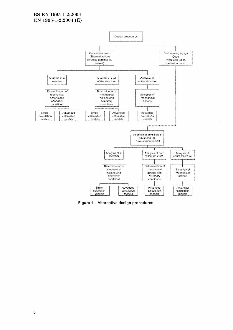
Options for the application of Part 1-2 of EN 1995 are illustrated in figure 1. The prescriptive and performance-based approaches are identified. The prescriptive approach uses nominal fires to generate thermal actions. The performance-based approach, using fire safety engineering, refers to thermal actions based on physical and cllemical parameters.
For design according to this part, EN 1991-1-2 is required for the determination of thermal and mechanical actions acting on the structure.
Design aids
It is expected that design aids based on the calculation models given in EN 1995-1-2, will be prepared by interested external organisations.
The main text of EN 1995-1-2 includes most of the principal concepts and rules necessary for direct application of structural fire design to timber structures.
In an annex F (informative), guidance is given to help the user select the relevant procedures for the design of timber structures.
National annex for EN 1995-1-2
This standard gives alternative procedures, values and recommendations with notes indicating where national choices may have to be made. Therefore the National Standard implementing EN 1995-1-2 should have a National annex containing all Nationally Determined Parameters to be used for the design of buildings and civil engineering works to be constructed in the relevant country.
National choice is allowed in EN 1995-1-2 through clauses: 2.1.3(2) Maximum temperature rise for separating function in parametric fire exposure; 2.3(1)P Partial factor for material properties; 2.3(2)P Partial factor for material properties; 2.4.2(3) Reduction factor for combination of actions; 4.2.1 (1) Method for determining cross-sectional properties.
7
BS EN 1995-1-2:2004 EN 1995-1-2:2004 (E)
Determlnotion of rna~h.)nic I actlons aM boundary conclition()
PrcJcnpti ru t :1
(Thermal actIOns yiVe!! iJy /luminal nil:!
curves}
Dc!crm ifiotiO!i of mochan1c-a1 act:lons ~na
boundar'/ conditiontJ
eChaf'\lca l actio(l& and
Sol · clion of mechanical
actions
Selection of $fmplified at t'jdVl'mr.Arl fin'"
development mod I
m~nical
act ons and
Figure 1 - Alternative design procedures
8
Pcrformoncc boGcd Code
(ptIYS!U<:IltY-[)<lSBU (!'letitia! actlon5)
Selectioh of m Chao n:a I
~~1.10!'lS
BS EN 1995-1-2:2004 EN 1995-1-2:2004 (E)
Section 1 General
1.1 Scope
1.1.1 Scope of Eurocode 5
(1)P Eurocode 5 applies to the design of buildings and civil engineering works in timber (solid timber, sawn, planed or in pole form, glued laminated timber or wood-based structural products, e.g. LVL) or wood-based panels jointed together with adhesives or mechanical fasteners. It complies with the principles and requirements for the safety and serviceability of structures and the basis of design and verification given in EN 1990:2002.
(2)P Eurocode 5 is only concerned with requirements for mechanical resistance, serviceability, durability and fire resistance of timber structures. Other requirements, e.g concerning thermal or sound insulation, are not considered.
(3) Eurocode 5 is intended to be used in conjunction with: EN 1990:2002 Eurocode - Basis of structural design" EN 1991 "Actions on structures" EN's for construction products relevant to timber structures EI\J 1998 "Design of structures for earthquake resistance", when timber structures are built in seismic regions.
(4) Eurocode 5 is subdivided into various parts: EN 1995-1 General EN 1995-2 Bridges
(5) EN 1995-1 "General" comprises: EN 1995-1-1 General- Common rules and rules for buildings EN 1995-1-2 General - Structural Fire Design
(6) EN 1995-2 refers to the General rules in EN 1995-1-1. The clauses in EN 1995-2 supplement the clauses in EN 1995-1.
1.1.2 Scope of EN 1995-1-2
(1)P EN 1995-1-2 deals with the design of timber structures for the accidental situation of fire exposure and is intended to be used in conjunction with EN 1995-1-1 and EN 1991-1-2:2002. EN 1995-1-2 only identifies differences from, or supplements normal temperature design.
(2)P EN 1995-1-2 deals only with passive methods of fire protection. Active methods are not covered.
(3)P EN 1995-1-2 applies to building structures that are required to fulfil certain functions when exposed to fire, in terms of - avoiding premature collapse of the structure (load-bearing function)
- limiting fire spread (flames, hot gases, excessive heat) beyond designated areas (separating function).
(4)P EN 1995-1-2 gives principles and application rules for designing structures for specified requirements in respect of the aforementioned functions and levels of performance.
(5)P EN 1995-1-2 applies to structures or parts of structures that are within the scope of EN 1995-1-1 and are designed accordingly.
(6)P The methods given in EN 1995-1-2 are applicable to all products covered by product standards made reference to in this Part.
9
BS EN 1995-1-2:2004 EN 1995-1-2:2004 (E)
1.2 Normative references
(1)P This European Standard incorporates by dated or undated reference, provisions from other publications. These normative references are cited at the appropriate places in the text and the publications are listed hereafter. For dated references, subsequent amendments to or revisions of any of these publications apply to this European Standard only when incorporated in it by amendment or revision. For undated references the latest edition of the publication referred to applies (including amendments).
European Standards:
EN 300
EN 301
EN 309 EN 313-1 EN 314-2 EN 316 ~ EN 520
EN 912 EN 1363-1 EN 1365-1 EN 1365-2 EN 1990:2002 EN 1991-1-1:2002
EN 1991-1-2:2002
EN 1993-1-2
EN 1995-1-1
EN 12369-1
EN 13162
ENV 13381-7
EN 13986
EN 14081-1
EN 14080 EN 14374
Oriented strand boards (OSB) - Definition, classification and specifications Adhesives, phenolic and aminoplastic for load-bearing timber structures; classification and periormance requirements Wood particleboards - Definition and classification Plywood Classification and terminology. Part 1: Classification Plywood Bonding quality. Part 2: Requirements Wood fibreboards - Definition, classification and symbols Gypsum plasterboards - Definitions, requirements and test methods @2] Timber fasteners - Specifications for connectors for timber Fire resistance tests Part 1: General requirements Fire resistance tests for loadbearing elements - Part 1: Walls Fire resistance tests for loadbearing elements - Part 2: Floors and roofs Eurocode: Basis of structural design Eurocode 1 Actions on structures Part 1-1: General actions Densities, self-weight and imposed loads for buildings Eurocode 1: Actions on structures - Part 1-2: General actions - Actions on structures exposed to fire Eurocode 3: Design of steel structures Part 1-2: General - Structural fire design Eurocode 5: Design of timber structures - Part 1-1: General - Common rules and rules for buildings Wood-based panels Characteristic values for structural design - Part 1: OSB, particleboards and fibreboards Thermal insulation products for buildings - factory-made mineral wool (MW) products - Specifications M/103 Test methods for determining the contribution to the fire resistance of structural members - Part 7: Applied protection to timber members Wood-based panels for use in construction - Characteristics, evaluation of conformity and marking Timber structures - Strength graded structural timber with rectangular cross section - Part 1, General requirements Timber structures - Glued laminated timber Requirements Timber structures - Structural laminated veneer lumber - Requirements
1.3 Assumptions
(1) In addition to the general assumptions of EN 1990:2002 it is assumed that any passive fire protection systems taken into account in the design of the structure will be adequately maintained.
1.4 Distinction between principles and application rules
(1)P The rules in EN 1990:2002 clause 1.4 apply.
10
BS EN 1995-1-2:2004 EN 1995-1-2:2004 (E)
1.5 Terms and definitions
(1)P The rules in EN 1990:2002 clause 1.5 and EN 1991-1-2 clause 1.5 apply.
(2)P The following terms and definitions are used in EN 1995-1-2 with the following meanings:
1.5.1 Char-line: Borderline between the char-layer and the residual cross-section.
1.5.2 Effective cross-section: Cross-section of member in a structural fire design based on the reduced cross-section method. It is obtained from the residual cross-section by removing the parts of the cross-section with assumed zero strength and stiffness.
1.5.3 Failure time of protection: Duration of protection of member against direct fire exposure; (e.g. when the fire protective cladding or other protection falls off the timber member, or when a structural member initially protecting the member fails due to collapse, or when the protection from another structural member is no longer effective due to excessive deformation).
1.5.4 Fire protection material: Any material or combination of materials applied to a structural member or element for the purpose of increasing its fire resistance.
1.5.5 Normal temperature design: Ultimate limit state design for ambient temperatures according to EN 1995-1-1.
1.5.6 Protected members: Members for which measures are taken to reduce the temperature rise in the member and to prevent or reduce charring due to fire.
1.5.7 Residual cross-section: Cross-section of the original member reduced by the charring depth.
1.6 Symbols
For the purpose of EN 1995-1-2, the following symbols apply:
Latin upper case letters
Ar Area of the residual cross-section At Total area of floors, walls and ceilings that enclose the fire compartment Av Total area of vertical openings of fire compartment
Design effect of actions Design modulus of elasticity in fire; design effect of actions for the fire situation Design effect of actions on a connection for the fire situation
FR,Q,2 20 % fractile of a resistance FRk Characteristic mechanical resistance of a connection at normal temperature
without the effect of load duration and moisture (kmod 1) Gd,fi Design shear modulus in fire Gk Characteristic value of permanent action Kfi Slip modulus in the fire situation Ku Slip modulus for the ultimate limit state at normal temperature L Height of storey a Opening factor Qk,1 Characteristic value of leading variable action
11
BS EN 1995-1-2:2004 EN 1995-1-2:2004 (E)
5 % fractile of a stiffness property (modulus of elasticity or shear modulus)at normal temperature 20 % fractile of a stiffness property (modulus of elasticity or shear modulus)at normal temperature Design stiffness property (modulus of elasticity or shear modulus) in the fire situation Section modulus of effective cross-section Section modulus of residual cross-section
Latin lower case letters
aO a1 a2 a3 afi
b bo b1
C
d do
dchar,o
dchar,n
def
dg f20
fd,fi
fk fv,k heq
hins
hp k kp
ko k2 k3 kfi
kflux
kh kj
kmod
kmod,E,fi
kmod,fi
kmod,fm,fi
kn
kpos
ke la
la,min
It Ip P qt,d
to
12
Parameter Parameter Distance Distance Extra thickness of member for improved mechanical resistance of connections Width; thermal absorptivity for the total enclosure Parameter Parameter Specific heat Diameter of fastener Depth of layer with assumed zero strength and stiffness Charring depth for one-dimensional charring Notional charring depth Effective charring depth Gap depth 20 % fractile strength at normal temperature Design strength in fire Characteristic strength Characteristic shear strength Weighted average of heights of all vertical openings in the fire compartment Insulation thickness Fire protective panel thickness Parameter Density coefficient Coefficient Insulation coefficient Post-protection coefficient Coefficient Heat flux coefficient for fasteners Panel thickness coefficient Joint coefficient Modification factor for duration of load and moisture content Modification factor for modulus of elasticity in the fire situation Modification factor for fire Modification factor for bending strength in the fire situation Notional cross-section coefficient Position coefficient Temperature-dependent reduction factor for local strength or stiffness property Penetration length of fastener into unburnt timber Minimum anchorage length of fastener Length of fastener Span of the panel Perimeter of the fire exposed residual cross-section Design fire load density related to the total area of floors, walls and ceilings which enclose the fire compartment Time of fire exposure Time period with a constant charring rate
BS EN 1995-1-2:2004 EN 1995-1-2:2004 (E)
t1 Thickness of the side member tch Time of start of charring of protected members (delay of start of charring due to
protection) td,fi Time of the fire resistance of the unprotected connection tf Failure time of protection tins Time of temperature increase on the unexposed side of the construction tins,O,i Basic insulation value of layer "i" tp,min Minimum thickness of panel tR Time of fire resistance with respect to the load-bearing function treq Required time of fire resistance y Co-ordinate z Co-ordinate
Greek upper case letters
r
e
Factor accounting for the thermal properties of the boundaries of the compartment Temperature
Greek lower case letters
Design charring rate for one-dimensional charring under standard fire exposure Design notional charring rate under standard fire exposure
}'rv1,fi
YQ,1
/L
P A (0
1f1,1
If/2.1
Iffi
Design charring rate during heating phase of parametric fire curve Conversion factor for the reduction of the load-bearing capacity in fire Conversion factor for slip modulus Partial factor for permanent actions in accidental design situations Partial factor for a material property, also accounting for model uncertainties and dimensional variations Partial factor for timber in fire Partial factor for leading variable action Thermal conductivity Density Characteristic density Moistu re content Combination factor for frequent value of a variable action Combination factor for quasi-permanent value of a variable action Combination factor for frequent values of variable actions in the fire situation
13
BS EN 1995-1-2:2004 EN 1995-1-2:2004 (E)
Section 2 Basis of design
2.1 Requirements
2.1.1 Basic requirements
(1)P Where mechanical resistance in the case of fire is required, structures shall be designed and constructed in such a way that they maintain their load-bearing function during the relevant fire exposure.
(2)P Where fire compartmentation is required, the elements forming the boundaries of the fire compartment, including joints, shall be designed and constructed in such a way that they maintain their separating function during the relevant fire exposure. This shall include, when relevant, ensuring that: - integrity failure does not occur;
- insulation failure does not occur;.
thermal radiation from the unexposed side is limited.
NOTE 1: See EN 1991-1-2:2002 for definitions.
NOTE 2: There is no risk of fire spread due to thermal radiation when an unexposed surface temperature is below 300°C.
(3)P Deformation criteria shall be applied where the means of protection, or the design criteria for separating elements, require that the deformation of the load-bearing structure is taken into account.
(4) Consideration of the deformation of the load-bearing structure is not necessary in the following cases, as relevant: - the efficiency of the means of protection has been proved according to 3.4.3 or 5.2;
the separating elements fulfil the requirements of a nominal fire exposure.
2.1.2 Nominal fire exposure
(1)P For standard fire exposure, elements shall comply with criteria R, E and I as follows: separating function only: integrity (criterion E) and, when requested, insulation (criterion I);
- load-bearing function only: mechanical resistance (criterion R);
- separating and load-bearing functions: criteria R, E and, when requested, I.
(2) Criterion R is assumed to be satisfied when the load-bearing function is maintained during the required time of fire exposure.
(3) Criterion I may be assumed to be satisfied where the average temperature rise over the whole of the non-exposed surface is limited to 140 K, and the maximum temperature rise at any point of that surface does not exceed 180 K.
2.1.3 Parametric fire exposure
(1) The load-bearing function should be maintained during the complete duration of the fire including the decay phase, or a specified period of time.
(2) For the verification of the separating function the following applies, assuming that the normal temperature is 20°C:
14
the average temperature rise of the unexposed side of the construction should be limited to 140 K and the maximum temperature rise of the unexposed side should not exceed 180 K
BS EN 1995-1-2:2004 EN 1995-1-2:2004 (E)
during the heating phase until the maximum temperature in the fire compartment is reached;
the average temperature rise of the unexposed side of the construction should be limited to L\B1 and the maximum temperature rise of the unexposed side should not exceed L\l9.2during the decay phase.
NOTE: The recommended values for maximum temperature rise during the decay phase are ile1 = 200 K and [email protected] = 240 K. Information on National choice may be found in the National annex.
2.2 Actions
(1)P Thermal and mechanical actions shall be taken from EN 1991-1-2:2002.
(2) For su rfaces of wood, wood-based materials and gypsum plasterboard the emissivity coefficient should be taken as equal to 0,8.
2.3 Design values of material properties and resistances
(1)P For verification of mechanical resistance, the design values of strength and stiffness properties shall be determined from
f d,fi = k mod,fi YM,fi
= kmod,fi YM,fi
where:
fd,fi is the design strength in fire;
(2.1 )
(2.2)
is the design stiffness property (modulus of elasticity or shear modulus Gd,fi) in fire;
f20 is the 20 % fractile of a strength property at normal temperature;
S20 is the 20 % fractile of a stiffness property (modulus of elasticity or shear modulus) at normal temperature;
kmod,fi is the modification factor for fire;
/1V1,fi is the partial safety factor for timber in fire.
NOTE 1: The modification factor for fire takes into account the reduction in strength and stiffness properties at elevated temperatures. The modification factor for fire replaces the modification factor for normal temperature design kmod given in EN 1995-1-1. Values of kmodJi are given in the relevant clauses.
NOTE 2: The recommended partial safety factor for material properties in fire is }1v1,fi = 1,0. Information on National choice may be found in the National annex ..
(2)P The design value Rd,t,fi of a mechanical resistance (load-bearing capacity) shall be calculated as
Rd,t,fi = '7 YI\J1,fi
where:
Rd,t,fi is the design value of a mechanical resistance in the fire situation at time t;
(2.3)
R20 is the 20 % frac1:ile value of a mechanical resistance at normal temperature without the effect of load duration and moisture (kmod = 1);
15
BS EN 1995-1-2:2004 EN 1995-1-2:2004 (E)
17 is a conversion factor;
YM,fi is the partial safety factor for timber in fire.
Note 1. See (1) above Note 2.
Note 2: Design resistances are applied for connections, see 6.2.2 and 6.4. For connections a conversion factor 77 is given in 6.2.2.1.
(3) The 20 % fractile of a strength or a stiffness property should be calculated as:
f20 = kfi fk
S20 = kfi S05
where:
f20 is the 20 % fractile of a strength property at normal temperature;
S20 is the 20 % fractile of a stiffness property (modulus of elasticity or shear modulus) at normal temperature;
is the 5 % fractile of a stiffness property (modulus of elasticity or shear modulus) at normal temperature
kr. is given in table 2.1.
Table 2.1 Values of kfi
kfi
Solid timber 1,25
Glued-laminated timber 1,15
Wood-based panels 1,15
LVL 1,1
Connections with fasteners in shear with side 1,15 members of wood and wood-based panels
Connections with fasteners in shear with side 1,05 members of steel
Connections with axially loaded fasteners 1,05
(4) The 20 % fractile of a mechanical resistance, R20 , of a connection should be calculated as
R20 = kfi Rk
where:
kfi is given in table 2.1.
Rk is the characteristic mechanical resistance of a connection at normal temperature without the effect of load duration and moisture (kmod = 1).
(5) For design values of temperature-dependent thermal properties, see 3.2.
2.4 Verification methods
2.4.1 General
(2.6)
(1)P The model of the structural system adopted for design shall reflect the performance of the structure in the fire situation.
(2)P It shall be verified for the required duration of fire exposure t:
16
(2.4)
(2.5)
BS EN 1995-1-2:2004 EN 1995-1-2:2004 (E)
Ed,fi ~ Rd,t,fi
where
(2.7)
Ed,fi is the design effect of actions for the fire situation, determined in accordance with EN 1991-1-2:2002, including effects of thermal expansions and deformations;
Rd,t,fi is the corresponding design resistance in the fire situation.
(3) The structural analysis for the fire situation should be carried out in accordance with EN 1990:2002 subclause 5.1.4.
NOTE: For verifying standard fire resistance requirements, a member analysis is sufficient.
(4)P The effect of thermal expansions of materials other than timber shall be taken into account.
(5) Where application rules given in EN 1995-1-2 are valid only for the standard temperaturetime curve, this is identified in the relevant clauses.
(6) As an alternative to design by calculation, fire design may be based on the results of fire tests, or on fire tests in combination with calculations, see EN 1990:2002 clause 5.2.
2.4.2 Member analysis
(1) The effect of actions should be determined for time t = 0 using combination factors (f/1,1 or (f/2,1 according to EN 1991-1-2:2002 clause 4.3.1.
(2) As a simplification to (1), the effect of actions normal temperature as:
may be obtained from the analysis for
Ed,fi = 'lfi Ed (2.8)
where:
is the design effect of actions for normal temperature design for the fundamental combination of actions, see EN 1990:2002;
'lfi is the reduction factor for the design load in the fire situation.
(3) The reduction factor '7fi for load combination (6.10) in EN 1990:2002 should be taken as
'hi (2.9)
or, for load combinations (6.1 Oa) and (6.1 Ob) in EN 1990:2002, as the smallest value given by the following two expressions
'lfi Gk + (f/fi Ok, 1
YG Gk + YO,1 0k,1
'lfi .; YG Gk + YO,1 0k,1
where:
Ok,1 is the characteristic value of the leading variable action;
Gk is the characteristic value of the permanent action;
YG is the partial factor for permanent actions;
YO,1 is the partial factor for variable action 1;
(2.9a)
(2.9b)
17
BS EN 1995-1-2:2004 EN 1995-1-2:2004 (E)
VIii is the combination factor for frequent values of variable actions in the fire situation, given either by V/1,1 or V/2,1, see EN 1991-1-1,
c; is a reduction factor for unfavourable permanent actions G.
NOTE 1: An example of the variation of the reduction factor 1Jfi versus the load ratio Qk,1/Gk for different values of the combination factor If/fi according to expression (2.9) is shown in figure 2.1 with the following assumptions: YGA = 1,0, YG = 1,35 and yo 1,5. Partial factors are specified in the relevant National annexes of EN 1990:2002. Expressions (2.9a) and (2.9b) give slightly higher values.
0,8
0,7
0.6 W ::: 0,9
'/ fj 0.5 n= 0,7
0,4 fi ;;;; 0,5
0,3
0,2 0 0.5 1.5 2 2,5 3
Figure 2.1 - Examples of reduction factor 17fi versus load ratio Qk,1/Gk according to expression (2.9)
NOTE 2: As a simplification, the recommended value is 1Jfi = 0,6, except for imposed loads according to category E given in EN 1991-2-1 :2002 (areas susceptible to accumulation of goods, including access areas) where the recommended value is rlfi 0,7. Information on National choice may be found in the National annex.
NOTE 3: The National choice of load combinations between expression (2.9) and expressions (2.9a) and (2.9b) is made in EN 1991-1-2:2002.
(4) The boundary conditions at supports may be assumed to be constant with time.
2.4.3 Analysis of parts of the structure
(1) 2.4.2(1) applies.
(2) As an alternative to carrying out a structural analysis for the fire situation at time t = 0, the reactions at supports and internal forces and moments at boundaries of part of the structure may be obtained from structural analysis for normal temperature as given in 2.4.2.
(3) The part of the structure to be analysed should be specified on the basis of the potential thermal expansions and deformations such that their interaction with other parts of the structure can be approximated by time-independent support and boundary conditions during fire exposure.
(4)P Within the part of the structure to be analysed, the relevant failure mode in fire, the temperature-dependent material properties and member stiffnesses, effects of thermal expansions and deformations (indirect fire actions) shall be taken into account.
(5) The boundary conditions at supports and the forces and moments at boundaries of the part of the structure being considered may be assumed to be constant with time.
18
BS EN 1995-1-2:2004 EN 1995-1-2:2004 (E)
2.4.4 Global structural analysis
(1)P A global structural analysis for the fire situation shall take into account: the relevant failure mode in fire exposure;
- the temperature-dependent material properties and member stiffnesses;
effects of thermal expansions and deformations (indirect fire actions).
19
BS EN 1995-1-2:2004 EN 1995-1-2:2004 (E)
Section 3 Material properties
3.1 General
(1)P Unless given as design values, the values of material properties given in this section shall be treated as characteristic values.
(2)P The mechanical properties of timber at 20°C shall be taken as those given in EN 1995-1-1 for normal temperature design.
3.2 Mechanical properties
(1) Simplified methods for the reduction of the strength and stiffness parameters of the crosssection are given in 4.1 and 4.2.
NOTE 1: A simplified method for the reduction of the strength and stiffness parameters of timber frame members in wall and floor assemblies completely filled with insulation is given in annex C (informative).
NOTE 2: A simplified method for the reduction of the strength of timber members exposed to parametric fires is given in annex A (informative).
(2) For advanced calculation methods, a non-linear relationship between strain and compressive stress may be applied.
NOTE: Values of temperature-dependent mechanical properties are given in annex B (informative).
3.3 Thermal properties
(1) Where fire design is based on a combination of tests and calculations, where possible, the thermal properties should be calibrated to the test results.
NOTE: For thermal analysis, design values of thermal conductivity and heat capacity of timber are given in annex B (informative).
3.4 Charring depth
3.4.1 General
(1)P Charring shall be taken into account for all surfaces of wood and wood-based panels directly exposed to fire, and, where relevant, for surfaces initially protected from exposure to fire, but where charring of the wood occurs during the relevant time of fire exposure.
(2) The charring depth is the distance between the outer surface of the original member and the position of the char-line and should be calculated from the time of fire exposure and the relevant charring rate.
(3)The calculation of cross-sectional properties should be based on the actual charring depth including corner roundings. Alternatively a notional cross-section without corner roundings may be calculated based on the notional charring rate.
(4) The position of the char-line should be taken as the position of the 300-degree isotherm.
NOTE: This assumption is valid for most softwoods and hardwoods.
(5) It should be taken into account that the charring rates are normally different for - surfaces unprotected throughout the time of fire exposure;
- initially protected surfaces prior to failure of the protection;
20
BS EN 1995-1-2:2004 EN 1995-1-2:2004 (E)
- initially protected surfaces when exposed to fire after failure of the protection.
(6) The rules of 3.4.2 and 3.4.3 apply to standard fire exposure.
NOTE: For parametric fire exposure, see annex A (informative).
3.4.2 Surfaces unprotected throughout the time of fire exposure
(1) The charring rate for one-dimensional charring, see figure 3.1, should be taken as constant with time. The design charring depth should be calculated as:
dchar,O = fio t
where:
(3.1 )
dchar,o is the design charring depth for one-dimensional charring;
fio is the one-dimensional design charring rate under standard fire exposure;
is the time of fire exposure.
Figure 3.1 - One-dimensional charring of wide cross section (fire exposure on one side)
(2) The notional charring rate, the magnitude of which includes for the effect of corner roundings and fissures, see figure 3.2, should be taken as constant with time. The notional design charring depth should be calculated as
dchar,n = fin t (3.2)
where:
dchar,n is the notional design charring depth, which incorporates the effect of corner roundings;
fin is the notional design charring rate, the magnitude of which includes for the effect of corner roundings and fissures.
(3) The one-dimensional design charring rate may be applied, provided that the increased charring near corners is taken into account, for cross-sections with an original minimum width, bmin , where
b - ' (3.3) {2 dChar 0 + 80 for dchar,O ~ 13 mm
min - 8,15 dchar,o for dchar,o < 13 mm
When the smallest width of the cross section is smaller than bmin , notional design charring rates should be applied.
(4) For cross-sections calculated using one-dimensional design charring rates, the radius of the corner roundings should be taken equal to the charring depth dchar,o.
21
BS EN 1995-1-2:2004 EN 1995-1-2:2004 (E)
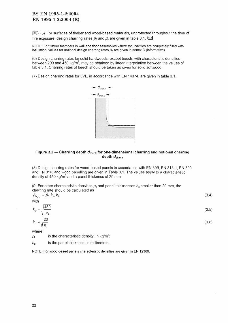
~ (5) For surfaces of timber and wood-based materials, unprotected throughout the time of fire exposure, design charring rates Po and Pn are given in table 3.1. @1]
NOTE: For timber members in wall and floor assemblies where the cavities are completely filled with insulation, values for notional design charring rates f3n are given in annex C (informative).
(6) Design charring rates for solid hardwoods, except beech, with characteristic densities between 290 and 450 kg/m3
, may be obtained by linear interpolation between the values of table 3.1. Charring rates of beech should be taken as given for solid softwood.
(7) Design charring rates for LVL, in accordance with EN 14374, are given in table 3.1 .
... d .n .~.
Figure 3.2 - Charring depth d char.O for one-dimensional charring and notional charring depth dchar,n
(8) Design charring rates for wood-based panels in accordance with EN 309, EN 313-1, EN 300 and EN 316 , and wood panelling are given in Table 3.1. The values apply to a characteristic density of 450 kg/m3 and a panel thickness of 20 mm.
(9) For other characteristic densities A and panel thicknesses hp smaller than 20 mm, the charring rate should be calculated as
/3o ,p,t = /30 k p kh
with
k = ~450 P Pk
kh = ~ ~ hp
where: A is the characteristic density, in kg/m3
;
hp is the panel thickness, in millimetres.
NOTE: For wood-based panels characteristic densities are given in EN 12369.
22
(3.4 )
(3.5)
(3 .6)
BS EN 1995-1-2:2004 EN 1995-1-2:2004 (E)
Table 3.1 - Design charring rates Po and Pn of timber, LVL, wood panelling and woodbased panels
Po Pn mm/min mm/min
a) Softwood and beech Glued laminated timber with a characteristic density of 290 kg/m3 0,65 0,7 Solid timber with a characteristic density of 0,65 0,8 290 kg/m3
b) Hardwood Solid or glued laminated hardwood with a 0,65 0,7 characteristic density of 290 kg/m3
Solid or glued laminated hardwood with a 0,50 0,55 characteristic density of 2 450 kg/m3
c) LVL with a characteristic density of 480 kg/m3 0,65 0,7
d) Panels Wood panelling 0,9a -Plywood 1,Oa -Wood-based panels other than plywood 0,9a -a The values apply to a characteristic density of 450 kg/m j and a panel thickness of 20 mm; see 3.4.2(9) for other thicknesses and densities.
3.4.3 Surfaces of beams and columns initially protected from fire exposure
3.4.3.1 General
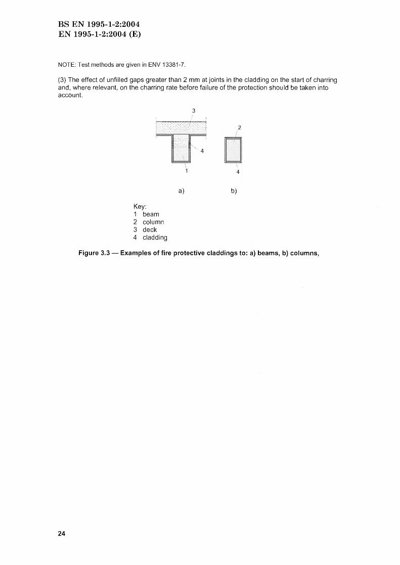
(1) For surfaces protected by fire protective claddings, other protection materials or by other structural members, see fjgure 3.3, it should be taken into account that
the start of charring is delayed until time tch ;
- charring may commence prior to failure of the fire protection, but at a lower rate than the charring rates shown in table 3.1 until failure time tf of the fire protection;
- after failure time tf of the fire protection, the charring rate is increased above the values shown in table 3.1 until the time fa described below;
I
- at the time fa when the charring depth equals either the charring depth of the same member without fire protection or 25 mm whichever is the lesser, the charring rate reverts to the value in table 3.1.
NOTE 1: Other fire protection available includes intumescent coatings and impregnation. Test methods are given in ENV 13381-7
NOTE 2: The protection provided by other structural members may be terminated due to failure or collapse of the protecting member; excessive deformation of the protecting member.
NOTE 3: The different stages of protection, the times of transition between stages and corresponding charring rates are illustrated in figures 3.4 to 3.6.
NOTE 4: Rules for assemblies with void cavities are given in annex D (informative).
(2) Unless rules are given below, the following should be assessed on the basis of tests: the time to the start of charring tch of the member;
the time for failure of the fire protective cladding or other fire protection material tf;
the charring rate before failure of the protection when tf > tch .
23
BS EN 1995-1-2:2004 EN 1995-1-2:2004 (E)
NOTE: Test methods are given in ENV 13381-7.
(3) The effect of unfilled gaps greater than 2 mm at joints in the cladding on the start of charring and, where relevant, on the charring rate before failure of the protection should be taken into account.
24
3
~ U···4
Key: 1 beam 2 column 3 deck 4 cladding
a)
4
b)
Figure 3.3 - Examples of fire protective claddings to: a) beams, b) columns,
BS EN 1995-1-2:2004 EN 1995-1-2:2004 (E)
40
Charring 30 2b
depth
20 or
[mm] 10 2a
0 if fa
Time t
Key: 1 Relationship for members unprotected throughout the time of fire exposure for
charring rate fJn (or f3o) 2 Relationship for initially protected members after failure of the fire protection 2a After the fire protection has fallen off, charring starts at increased rate 2b After char depth exceeds 25 mm charring rate reduces to the rate shown in table
3.1
Figure 3.4 - Variation of charring depth with time when tch = tf and the charring depth at time ta is at least 25 mm
40
Charring 30 depth
or 20
[mm] 10
o
Key:
/
Timet
1 Relationship for members unprotected throughout the time of fire exposure for charring rate shown in table 3.1
3 Relationship for initially protected members with failure times of fire protection tf and time limit ta smaller than given by expression (3.8b)
Figure 3.5 -Variation of charring depth with time when tch = tf and the charring depth at time ta is less than 25 mm
25
BS EN 1995-1-2:2004 EN 1995-1-2:2004 (E)
40
Charring 30 depth
or
d cha!',n
20
[mm] 10
o
Key:
2c
2b d char.O :::.:: 25 mm
or :::: 2Smm
2a ~
/'
1 Relationship for members unprotected throughout the time of fire exposure for charring rate fJn (or f3o)
2 Relationship for initially protected members where charring starts before failure of protection:
2a Charring starts at tch at a reduced rate when protection is still in place 2b After protection has fallen off, charring starts at increased rate 2c After char depth exceeds 25 mm charring rate reduces to the rate shown in table
3.1
Figure 3.6 - Variation of charring depth with time when tch < tf
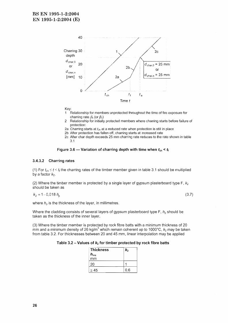
3.4.3.2 Charring rates
(1) For tch t tf the charring rates of the timber member given in table 3.1 should be multiplied by a factor k2.
(2) Where the timber member is protected by a single layer of gypsum plasterboard type F, k2 should be taken as
where hp is the thickness of the layer, in millimetres.
Where the cladding consists of several layers of gypsum plasterboard type F, hp should be taken as the thickness of the inner layer.
(3.7)
(3) Where the timber member is protected by rock fibre batts with a minimum thickness of 20 mm and a minimum density of 26 kg/m3 which remain coherent up to 1000°C, k2 may be taken from table 3.2. For thicknesses between 20 and 45 mm, linear interpolation may be applied
Table 3.2 - Values of k2 for timber protected by rock fibre batts
I Thickness k2 hins
Imm
20 1
~45 0,6
26
BS EN 1995-1-2:2004 EN 1995-1-2:2004 (E)
(4) For the stage after failure of the protection given by tf s t s ta, the charring rates of table 3.1 should be multiplied by a factor k3 = 2. For t 2 ta the charring rates of table 3.1 should be applied without multiplication by k3 .
(5) The time limit ta, see figure 3.4 and 3.5, should for tf be taken as
f2 tf (a)
ta min l 25 --+tf (b) (3.8)
k313n
or for tch < tf (see figure 3.6)
(3.9)
where 13n is the notional design charring rate, in mm/min. Expressions (3.8) and (3.9) also apply to one-dimensional charring when 13n is replaced by 130'
For the calculation of tf see 3.4.3.4.
NOTE: Expression (3.8b) implies that a char-layer of 25 mm gives sufficient protection to reduce the charring rate to the values of table 3.1.
3.4.3.3 Start of charring
(1) For fire protective claddings consisting of one or several layers of wood-based panels or wood panelling, the time of start of charring tch of the protected timber member should be taken as
hp tch = 130 (3.10)
where:
hp is the thickness of the panel, in case of several layers the total thickness of layers;
tch is the time of start of charring;
(2) For claddings consisting of one layer of gypsum plasterboard of type A, F or H according to EN 520, at internal locations or at the perimeter adjacent to filled joints, or unfilled gaps with a width of 2 mm or less, the time of start of charring tch should be taken as
(3.11 )
where:
hp is the thickness of the panel, in mm.
At locations adjacent to joints with unfilled gaps with a width of more than 2 mm, the time of start of charring tch should be calculated as
tch 2,8 hp - 23 (3.12)
where:
hp is the thickness of the panel, in mm;
NOTE: Gypsum plasterboard type E, 0, R and I according to EN 520 have equal or better thermal and mechanical properties than type A and H.
(3) For claddings consisting of two layers of gypsum plasterboard of type A or H, the time of start of charring tCh should be determined according to expression (3.11) where the thickness hp
27
BS EN 1995-1-2:2004 EN 1995-1-2:2004 (E)
is taken as the thickness of the outer layer and 50 % of the thickness of the inner layer, provided that the spacing of fasteners in the inner layer is not greater than the spacing of fasteners in the outer layer.
(4) For claddings consisting of two layers of gypsum plasterboard of type F, the time of start of charring tch should be determined according to expression (3.11) where the thickness hp is taken as the the thickness of the outer layer and 80 % of the thickness of the inner layer, provided that the spacing of fasteners in the inner layer is not greater than the spacing of fasteners in the outer layer.
(5) For beams or columns protected by rock fibre batts as specified in 3.4.3.2(3), the time of start of charring tch should be taken as
tCh = 0,07 (hins - 20) (3.13)
where:
tch is the time of start of charring in minutes;
hins is the thickness of the insulation material in millimetres;
Pms is the density of the insulating material in kg/m 3.
3.4.3.4 Failure times of fire protective claddings
(1) Failure of fire protective claddings may occur due to - charring or mechanical degradation of the material of the cladding;
insufficient penetration length of fasteners into uncharred timber;
- inadequate spacing and distances of fasteners.
(2) For fire protective claddings of wood panelling and wood-based panels attached to beams or columns, the failure time should be determined according to the following: tf tch (3.14)
where tch is calculated according to expression (3.10).
(3) For gypsum plasterboard type A and H the failure time tf should be taken as:
(3.15)
where tch is calculated according to expression 3.4.3.3(3).
NOTE: In general, failure due to mechanical degradation is dependent on temperature and size of the panels and their orientation. Normally, vertical position is more favourable than horizontal.
(4) The penetration length la of fasteners into uncharred timber should be at least 10 mm. The required length of the fastener h,req should be calculated as
(3.16)
where:
hp is the panel thickness;
dchar,Q is the charring depth in the timber member;
la is the minimum penetration length of the fastener into uncharred timber.
Increased charring near corners should be taken into account, see 3.4.2(4).
28
BS EN 1995-1-2:2004 EN 1995-1-2:2004 (E)
3.5 Adhesives
(1)P Adhesives for structural purposes shall produce joints of such strength and durability that the integrity of the bond is maintained in the assigned fire resistance period.
NOTE: For some adhesives, the softening temperature is considerably below the charring temperature of the wood.
(2) For bonding of wood to wood, wood to wood-based materials or wood-based materials to wood-based materials, adhesives of phenol-formaldehyde and aminoplastic type 1 adhesive according to EN 301 may be used. For plywood and LVL, adhesives according to EN 314 may be used.
29
BS EN 1995-1-2:2004 EN 1995-1-2:2004 (E)
Section 4 Design procedures for mechanical resistance
4.1 General
(1) The rules of EN 1995-1-1 apply in conjunction with cross-sectional properties determined according to 4.2 and 4.3 and the additional rules for analysis given in 4.3. For advanced calculation methods, see 4.4.
4.2 Simplified rules for determining cross-sectional properties
4.2.1 General
(1) The section properties should be determined by the rules given in either 4.2.2 or 4.2.3.
NOTE: The recommended procedure is the reduced cross-section method given in 4.2.2. Information on the National choice may be found in the National annex.
4.2.2 Reduced cross-section method
(1) An effective cross-section should be calculated by reducing the initial cross-section by the effective charring depth def (see figure 4.1)
def = dchar ,n + ko do (4.1 )
with:
do = 7 mm
dchar,n is determined according to expression (3.2) or the rules given in 3.4.3.
ko is given in (2) and (3).
NOTE: It is assumed that material close to the char line in the layer of thickness ko do has zero strength and stiffness, while the strength and stiffness properties of the remaining cross-section are assumed to be unchanged.
Key
1
2 3
~char, n ko do
def
1 Initial surface of member 2 Border of residual cross-section 3 Border of effective cross-section
Figure 4.1 - Definition of residual cross-section and effective cross-section
(2) For unprotected surfaces, ko should be determined from table 4.1.
30
BS EN 1995-1-2:2004 EN 1995-1-2:2004 (E)
Table 4.1 - Determination of ko for unprotected surfaces with t in minutes (see figure 4.2a)
(3) For protected surfaces with tch > 20 minutes, it should be assumed that ko varies linearly from ° to 1 during the time interval from t = ° to t tch , see figure 4.2b. For protected surfaces with tCh ::;; 20 minutes table 4.1 applies.
o o 20
Time [min]
a)
ko
o o 20 t = t ch
Time [min]
b)
Figure 4.2 - Variation of ko: a) for unprotected members and protected members where tch S 20 minutes, b) for protected members where tch > 20 minutes
(4) For timber surfaces facing a void cavity in a floor or wall assembly (normally the wide sides of a stud or a joist), the following applies:
Where the fire protective cladding consists of one or two layers of gypsum plasterboard type A, wood panelling or wood-based panels, at the time of failure tf of the cladding, ko should be taken as 0,3. Thereafter ko should be assumed to increase linearly to unity during the following 15 minutes;
Where the fire protective cladding consists of one or two layers of gypsum plasterboard type F, at the time of start of charring tch , ko should be taken as unity. For times t < tchl linear interpolation should be applied, see figure 4.2b.
(5) The design strength and stiffness properties of the effective cross-section should be calculated with kmod,fi = 1,0.
4.2.3 Reduced properties method
(1) The following rules apply to rectangular cross-sections of softwood exposed to fire on three or four sides and round cross-sections exposed along their whole perimeter.
(2) The residual cross-section should be determined according to 3.4.
(3) For t ~ 20 minutes, the modification factor for fire kmod,fi, see 2.3 (1 )P, should be taken as follows (see figure 4.3):
for bending strength:
1 k df,=10
rno ,I ' 200 A
for compressive strength:
(4.2)
31
BS EN 1995-1-2:2004 EN 1995-1-2:2004 (E)
kmod,fi 1 P 10---
, 125 A-
for tensile strength and modulus of elasticity:
kmod,fi 10 __ 1_ , 330 A-
where:
p is the perimeter of the fire exposed residual cross-section, in metres;
Ar is the area of the residual cross-section, in m2.
(4.3)
(4.4)
(4) For unprotected and protected members, for time t 0 the modification factor for fire should be taken as kmod,fi = 1. For unprotected members, for 0 ::; t::; 20 minutes the modification factor may be determined by linear interpolation.
Figure 4.3 -Illustration of expressions (4.2)-(4.4)
100
4.3 Simplified rules for analysis of structural members and components
4.3.1 General
(1) Compression perpendicular to the grain may be disregarded.
(2) Shear may be disregarded in rectangular and circular cross-sections. For notched beams it should be verified that the residual cross-section in the vicinity of the notch is at least 60 % of the cross-section required for normal temperature design.
4.3.2 Beams
(1) Where bracing fails during the relevant fire exposure, the lateral torsional stability of the beam should be considered without any lateral restraint from that bracing.
32
BS EN 1995-1-2:2004 EN 1995-1-2:2004 (E)
4.3.3 Columns
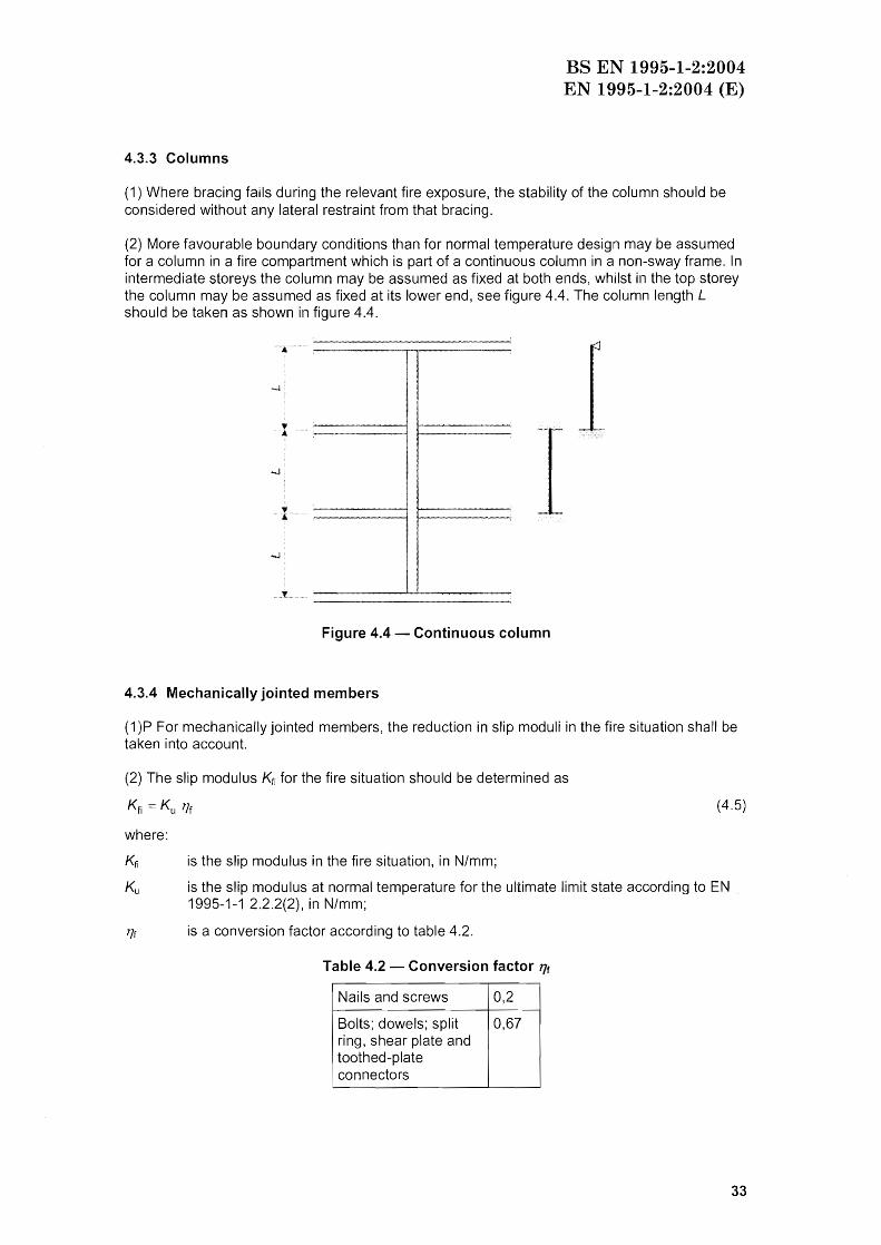
(1) Where bracing fails during the relevant fire exposure, the stability of the column should be considered without any lateral restraint from that bracing.
(2) More favourable boundary conditions than for normal temperature design may be assumed for a column in a fire compartment which is part of a continuous column in a non-sway frame. In intermediate storeys the column may be assumed as fixed at both ends, whilst in the top storey the column may be assumed as fixed at its lower end, see figure 4.4. The column length L should be taken as shown in figure 4.4.
····1
.. T.
1 I
Figure 4.4 - Continuous column
4.3.4 Mechanically jointed members
(1)P For mechanically jointed members, the reduction in slip moduli in the fire situation shall be taken into account.
(2) The slip modulus Kfi for the fire situation should be determined as
Kfi Ku 17f (4.5)
where:
Kfi is the slip modulus in the fire situation, in N/mm;
Ku is the slip modulus at normal temperature for the ultimate limit state according to EN 1995-1-1 2.2.2(2), in N/mm;
'If is a conversion factor according to table 4.2.
Table 4.2 - Conversion factor l1f
Nails and screws 0,2
Bolts; dowels; split 0,67 ring, shear plate and toothed-plate
i connectors
33
BS EN 1995-1-2:2004 EN 1995-1-2:2004 (E)
4.3.5 Bracings
(1) Where members in compression or bending are designed taking into account the effect of bracing, it should be verified that the bracing does not fail during the required duration of the fire exposure.
(2) Bracing members made of timber or wood-based panels may be assumed not to fail if the residual thickness or cross-sectional area is 60 % of its initial value required for normal temperature design, and is fixed with nails, screws, dowels or bolts.
4.4 Advanced calculation methods
(1)P Advanced calculation methods for determination of the mechanical resistance and the separating function shall provide a realistic analysis of structures exposed to fire. They shall be based on fundamental physical behaviour in such a way as to lead to a reliable approximation of the expected behaviour of the relevant structural component under fire conditions.
NOTE: Guidance is given in annex B (informative).
34
BS EN 1995-1-2:2004 EN 1995-1-2:2004 (E)
Section 5 Design procedures for wall and floor assemblies
5.1 General
(1) The rules in this subclause apply to load-bearing (R) constructions, separating (EI) constructions, and load-bearing and separating (REI) constructions. For the separating function the rules only apply for standard fire resistances not exceeding 60 minutes.
5.2 Analysis of load-bearing function
~ (1)P Non-separating load-bearing constructions shall be designed for fire exposure on both sides at the same time. @1]
NOTE 1: For wall and floor assemblies with cavities completely filled with insulation a design method is given in annex C (informative).
NOTE 2: For wall and floor assemblies with void cavities, design rules are given in annex 0 (informative).
5.3 Analysis of separating function
(1) The analysis should take into account the contributions of different material components and their position in the assembly.
NOTE: A design method is given in annex E (informative).
35
BS EN 1995-1-2:2004 EN 1995-1-2:2004 (E)
Section 6 Connections
6.1 General
(1) This section applies to connections between members under standard fire exposure, and unless stated otherwise, for fire resistances not exceeding 60 minutes. Rules are given for connections made with nails, bolts, dowels, screws, split-ring connectors, shear-plate connectors and toothed-plate connectors.
(2) The rules of 6.2 and 6.3 apply to laterally loaded symmetrical three-member connections. Clause 6.4 deals with axially loaded screws.
6.2 Connections with side members of wood
6.2.1 Simplified rules
6.2.1.1 Unprotected connections
(1) The fire resistance of unprotected wood-to-wood connections where spacings, edge and end distances and side member dimensions comply with the minimum requirements given in EN 1995-1-1 section 8, may be taken from table 6.1.
Table 6.1 -Fire resistances of unprotected connections with side members of wood
Time of fire Provisionsa
resistance td,fi
ITI in
Nails 15 d~ 2,8 mm
Screws 15 d~ 3,5 mm
Bolts 15 t1 ~ 45 mm
Dowels 20 t1 ~ 45 mm
Connectors according to 15 t1 ~ 45 mm EN 912 a d is the diameter of the fastener and t1 is the thickness of the side member
(2) For connections with dowels, nails or screws with non-projecting heads, fire resistance periods td,fi greater than those given in table 6.1, but not exceeding 30 minutes, may be achieved by increasing the following dimensions by 8fi:
- the thickness of side members,
- the width of the side members,
- the end and edge distance to fasteners.
where:
fin is the charring rate according to table 3.1;
kflux is a coefficient taking into account increased heat flux through the fastener;
treq is the required standard fire resistance period;
td,fi is the fire resistance period of the unprotected connection given in table 6.1.
36
(6.1 )
BS EN 1995-1-2:2004 EN 1995-1-2:2004 (E)
o 0
o 0
Figure 6.1 - Extra thickness and extra end and edge distances of connections
(3) The factor kflux should be taken as kf1ux 1,5.
6.2.1.2 Protected connections
(1) When the connection is protected by the addition of wood panelling, wood-based panels or gypsum plasterboard type A or H, the time until start of charring should satisfy
(6.2)
where:
tch is the time until start of charring according to 3.4.3.3;
treq is the required standard fire resistance period;
td,fi is the fire resistance of the unprotected connection given in table 6.1.
(2) When the connection is protected by the addition of gypsum plasterboard type F , the time until start of charring should satisfy
(6.3)
(3) For connections where the fasteners are protected by glued-in timber plugs, the length of the plugs should be determined according to expression (6.1), see figure 6.2.
(4) The fixings of the additional protection should prevent its premature failure. Additional protection provided by wood-based panels or gypsum plasterboard should remain in place until charring of the member starts (t = tCh)' Additional protection provided by gypsum plasterboard type F should remain in place during the required fire resistance period (t = treq ).
(5) In bolted connections the bolt heads should be protected by a protection of thickness 8fj, see figure 6.3.
(6) The following rules apply for the fixing of additional protection by nails or screws: the distance between fasteners should be not more than 100 mm along the board edges and not more than 300 mm for internal fastenings;
the edge distance of fasteners should be equal or greater than 8fi calculated using expression (6.1), see figure 6.2.
37
BS EN 1995-1-2:2004 EN 1995-1-2:2004 (E)
(7) The penetration depth of fasteners fixing of the additional protection made of wood, woodbased panels or gypsum plasterboard type A or H should be at least 6d where d is the diameter of the fastener. For gypsum plasterboard type F, the penetration length into unburnt wood (that is beyond the char-line) should be at least 10 mm, see figure 7.1 b.
Figure 6.2 - Examples of additional protection from glued-in plugs or from wood-based panels or gypsum plasterboard (the protection of edges of side and middle members is
not shown)
1
2
Key: 1 Member 2 Bolt head 3 Member providing protection
Figure 6.3 - Example of protection to a bolt head
6.2.1.3 Additional rules for connections with internal steel plates
(1) For joints with internal steel plates of a thickness equal or greater than 2 mm, and which do not project beyond the timber surface, the width bst of the steel plates should observe the conditions given in table 6.2.
38
BS EN 1995-1-2:2004 EN 1995-1-2:2004 (E)
Table 6.2 - Widths of steel plates with unprotected edges
bst
Unprotected edges in R 30 2:: 200 mm general R 60 2:: 280 mm Unprotected edges on R 30 2::120 mm one or two sides R 60 2:: 280 mm
(2) Steel plates narrower than the timber member may be considered as protected in the following cases (see figure 6.4): - For plates with a thickness of not greater than 3 mm where the gap depth dg is greater than
20 mm for a fire resistance period of 30 minutes and greater than 60 mm for a fire resistance period of 60 minutes;
- For joints with glued-in strips or protective wood-based boards where the depth of the gluedin strip, dg, or the panel thickness, hp, is greater than 10 mm for a fire resistance period of 30 minutes and greater than 30 mm for a fire resistance period of 60 minutes.
a) b) c) d)
Figure 6.4 - Protection of edges of steel plates (fasteners not shown): a) unprotected, b) protected by gaps, c) protected by glued-in strips, d) protected by panels
6.2.2 Reduced load method
6.2.2.1 Unprotected connections
~ (1) The rules for bolts and dowels are valid where the thickness of the side plate is equal or greater than t1, in mm: @l]
{
50 t = max 1 50 + 1,25 ( d -12)
where d is the diameter of bolt or dowel, in mm.
(2) For standard fire exposure, the characteristic load-carrying capacity of a connection with fasteners in shear should be calculated as
Fv,Rk,fi = 17 Fv,Rk
with
-ktdfi 17 = e , I
where:
(6.4 )
(6.5)
(6.6)
Fv,Rk is the characteristic lateral load-carrying capacity of the connection with fasteners in shear at normal temperature, see EN 1995-1-1 section 8;
39
BS EN 1995-1-2:2004 EN 1995-1-2:2004 (E)
'7 is a conversion factor;
k is a parameter given in table 6.3;
td.fi is the design fire resistance of the unprotected connection, in minutes.
NOTE: The design load-bearing capacity is calculated corresponding to 2.3 (2)P.
(3) The design fire resistance of the unprotected connection loaded by the design effect of actions in the fire situation, see 2.4.1, should be taken as:
_~ In 17fi 170 kmod rM,fi tdJi
k
where:
k is a parameter given in table 6.3;
77fi is the reduction factor for the design load in the fire situation, see 2.4.2 (2);
770 is the degree of utilisation at normal temperature;
kmod is the modification factor from EN 1995-1-1, subclause 3.1.3;
1M is the partial factor for the connection, see EN 1995-1-1, subclause 2.4.1;
kfi is a value according to 2.3 (4);
IM,fi is the partial safety factor for timber in fire, see 2.3(1). @II
Table 6.3 - Parameter k
Connection with k Maximum period of validity for
parameter k in an unprotected connection
min
Nails and screws 0,08 20
wood-to-wood with d'? 12 mm 0,065 30
steel-to-wood with d'? 12 mm 0,085 30
Dowels wood-to-wooda with d'? 12 mm 0,04 40
Dowels steel-to-wood3 with d'? 12 mm 0,085 30
Connectors in accordance with EN 912 0,065 30 a The values for dowels are dependent on the presence of one bolt for every four dowels
(4) For dowels projecting more than 5 mm, values of k should be taken as for bolts.
(6.7)
(5) For connections made of both bolts and dowels, the load-bearing capacity of the connection should be taken as the sum of the load-bearing capacities of the respective fasteners.
(6) For connections with nails or screws with non-projecting heads, for fire resistances greater than given by expression (6.7) but not more than 30 minutes, the side member thickness and end and edge distances should be increased by afi (see figure 6.1) which should be taken as:
(6.8)
where:
jJn is the notional charring rate according to table 3.1;
treq is the required standard fire resistance;
40
BS EN 1995-1-2:2004 EN 1995-1-2:2004 (E)
td,fi is the fire resistance of the unprotected connection loaded by the design effect of actions in the fire situation, see 2.4.1.
6.2.2.2 Protected connections
(1) Subclause 6.2.1.2 applies, except that td,fi should be calculated according to expression (6.7).
(2) As an alternative method of protecting end and side surfaces of members, the end and edge distances may be increased by 8fi accordding to expression (6.1). For fire resistances greater than 30 minutes, however, the end distances should be increased by 28fi' This increase in end distance also applies for butted central members in a connection.
6.3 Connections with external steel plates
6.3.1 Unprotected connections
(1) The load-bearing capacity of the external steel plates should be determined according to the rules given in EN 1993-1-2.
(2) For the calculation of the section factor of the steel plates according to EN 1993-1-2, it may be assumed that steel surfaces in close contact with wood are not exposed to fire.
6.3.2 Protected connections
(1) Steel plates used as side members may be considered as protected if they are totally covered, including at edges of plate, by timber or wood-based panels with a minimum thickness of 8fi according to expression (6.1) with td,fi = 5 min.
(2) The effect of other fire protections should be calculated according to EN 1993-1-2.
6.4 Simplified rules for axially loaded screws
(1) For axially loaded screws that are protected from direct fire exposure, the following rules apply.
(2) The design resistance of the screws should be calculated according to expression (2.3).
(3) For connections where the distances 82 and 83 of the fastener satisfy expressions (6.9) and (6.10), see figure 6.5, the conversion factor 17 for the reduction in the axial resistance of the screw in the fire situation should be calculated using expression (6.11):
8 2 ~ 8 1 + 40
8 3 ~ 8 1 + 20
where 81, 82 and 83 are the distances, in millimetres.
° 0,44
0,2 td,fi +5
77 = 10,56 81 0,36· td,fi + 7,32
0,2 td,fj + 23
1,0
where:
for 81 ::;; 0,6 tfj,d
for 0,6 td,fi ::;; 8 1 0,8 td,fi + 5
for 0,8 td,fj + 5::;; 8 1 ::;; td,fi + 28
for 8 1 td.fi +28
(a)
(b)
(c)
(d)
(6.9)
(6.10)
(6.11 )
41
BS EN 1995-1-2:2004 EN 1995-1-2:2004 (E)
81 is the side cover in mm, see figure 6.5;
td,fi is the required fire resistance period, in minutes.
(4) The conversion factor 77 for fasteners with edge distances 82 = 81 and 83 ::::: 81 + 20 mm should be calculated according to expression (6.11) where td,fi is replaced by 1,25 td,fi.
8 1 82 ....... ...
Figure 6.5 - Cross-section and definition of distances
42
BS EN 1995-1-2:2004 EN 1995-1-2:2004 (E)
Section 7 Detailing
7.1 Walls and floors
7.1.1 Dimensions and spacings
(1) The spacing of wall studs and floor joists should not be greater than 625 mm.
(2) For walls, individual panels should have a minimum thickness of
f Ip Ip,min max l;O (7.1 )
where:
tp,min is the minimum thickness of panel in millimetres;
Ip is the span of the panel (spacing between timber frame members or battens) in millimetres.
(3) Wood-based panels in constructions with a single layer on each side should have a characteristic density of at least 350 kg/m3
.
7.1.2 Detailing of panel connections
(1) Panels should be fixed to the timber frame or battens.
(2) For wood-based panels and wood panelling, the maximum spacing of nails and screws around the perimeter should be 150 mm and 250 mm respectively. The minimum penetration length should be eight times the fastener diameter for load-bearing panels and six times the fastener diameter for non-load-bearing panels.
(3) For gypsum plasterboard of types A and H, it is sufficient to observe the rules for normal temperature design with respect to penetration length, spacings and edge distances. For screws, however, the perimeter and internal spacing should not be greater than 200 mm and 300 mm respectively.
(4) For gypsum plasterboard type F panels, the penetration length la of fasteners into the residual cross-section should not be less than 10 mm, see figure 7.1.
(5) Panel edges should be tightly jointed with a maximum gap of 1 mm. They should be fixed to the timber member or battens on at least two opposite edges.
(6) For multiple layers the panel joints should be staggered by at least 60 mm. Each panel should be fixed individually.
7.1.3 Insulation
(1) Insulating layers or boards that are taken into account in the calculation should be tightly fitted and fixed to the timber frame such that premature failure or slumping is prevented.
7.2 Other elements
(1) Fire protective wood-based panels or wood panelling protecting members such as beams and columns should be fixed by nails or screws to the member according to figure 7.2. Panels should be fixed to the member itself and not to another panel. For claddings consisting of multiple layers of panels each layer should be fixed individually, and joints should be staggered by at least 60 mm. The spacing of fasteners should not be greater than 200 mm or 17 times the
43
BS EN 1995-1-2:2004 EN 1995-1-2:2004 (E)
panel tbickness hp, whichever is the smallest. With reference to fastener length, 7.1.2(1 )-(2) applies, see figure 7.1 b. The edge distance should not be greater than 3 times the panel thickness hp and not be smaller than 1,5 times the panel thickness or 15 mm, whichever is the smallest.
Figure 7.1 - Timber members protected by gypsum plasterboard - Examples of penetration length of fastener into unburnt timber: a) Timber frame assembly with
insulation in cavity, b) Wide timber member in general
Figure 7.2 - Examples of fixing of fire protective panels to beams or columns
44
BS EN 1995-1-2:2004 EN 1995-1-2:2004 (E)
Annex A (Informative) Parametric fire exposure
A1 General
(1) This Annex deals with natural fire exposure according to the opening factor method using parametric time-temperature curves.
NOTE: A method for the determination of parametric time-temperature curves is given in EN 1991-1-2:2002, annex A.
A2 Charring rates and charring depths
(1) For unprotected softwood the relation between the charring rate f3 and time t shown in figure A 1 should be used. The charring rate f3par during the heating phase of a parametric fire curve is given by
15 ~ 0,2# - 0,04 , n 0,16# +0,08
with
(%)' r (~J2
1160
O=Av ~ A ,\/"eq
t
b
where:
o is the opening factor, in mO.5;
f3n is the notional design charring rate, in mm/min;
(A.1 )
(A.2)
(A.3)
(A.4)
(A.5)
Av is the total area of openings in vertical boundaries of the compartment (windows etc.), in m2
;
At is the total area of floors, walls and ceilings that enclose the fire compartment, in m2;
A is the area of vertical opening "ill, in m2;
heq is the weighted average of heights of all vertical openings (windows etc.), in metres;
hi is the height of vertical opening "i", in metres;
r is a factor accounting for the thermal properties of the boundaries of the compartment;
b is the absorptivity for the total enclosure, see EN 1991-1-2:2002, annex A;
A is the thermal conductivity of the boundary of the compartment, in Wm-1K-1;
p is the density of the boundary of the compartment, in kg/m3;
G is the specific heat of the boundary of the compartment, in Jkg-1K-1.
45
BS EN 1995-1-2:2004 EN 1995-1-2:2004 (E)
fJ [mm/min]
/3 par
o to
Time
Figure A 1 - Relationship between charring rate and time
(2) The charring depth should be taken as
fJpar t for t s; to (a)
~ dchar = r t2
fJpar 1,5t-\ 4to
for to < t s; 3to (b)
2fJparto for 3to < t s; 5to (c)
with
to 0,009 0
where:
to is the time period with a constant charring rate, in minutes;
is the design fire load density related to the total area of floors, walls and ceilings which enclose the fire compartment in MJ/m2
, see EN 1991-1-2:2002.
The rules given in (1) and (2) should only be used for:
to s:; 40 min
dchar b
4
- d <12 char - 4
where:
b is the width of the cross-section;
h is the depth of the cross-section.
46
(A.6) @2]
(A.7)
BS EN 1995-1-2:2004 EN 1995-1-2:2004 (E)
A3 Mechanical resistance of members in edgewise bending
(1) For members under edgewise bending with an initial width b ~ 130 mm exposed to fire on three sides the mechanical resistance during the complete fire duration may be calculated using the residual cross-section. The residual cross-section of the member should be calculated by reducing the initial cross-section by the charring depth according to expression (A.6).
(2) For softwoods the modification factor for fire kmod,fi should be calculated according to the following:
for t ~ 3to the modification factor for fire should be calculated according to expression (4.2)
- for t = 5to as
kmod,fi 1,0 - 3,2 b
(A.B)
where:
dchar,n is the notional charring depth;
b is the width of the member.
For 3to ~ t ~ 5to the modification factor for fire may be determined by linear interpolation.
NOTE: Where the reduced properties method given in 4.2.3 is invalidated by the National annex, for t s; 3to the modification factor for fire can be derived from the reduced cross-section method as
(A.9)
where:
Wef is the section modulus of the effective cross-section determined according to 4.2.2;
Wr is the section modulus of the residual cross-section.
47
BS EN 1995-1-2:2004 EN 1995-1-2:2004 (E)
Annex B (informative) Advanced calculation methods
B1 General
(1) Advanced calculation models may be used for individual members, parts of a structure or for entire structures.
(2) Advanced calculation methods may be applied for: the determination of the charring depth;
the development and distribution of the temperature within structural members (thermal response model);
the evaluation of structural behaviour of the structure or of any part of it (structural response model).
(3) The ambient temperature should be taken as 20°C.
(4) Advanced calculation methods for thermal response should be based on the theory of heat transfer.
(5) The thermal response model Sllould take into account the variation of the thermal properties of the material with temperature.
NOTE: Where thermal models do not take into account phenomena such as increased heat transfer due to mass transport, e.g. due to the vaporisation of moisture, or increased heat transfer due to cracking which causes heat transfer by convection and/or radiation, the thermal properties are often modified in order to give results that can be verified by tests.
(6) The influence of any moisture content in the timber and of protection from gypsum plasterboard should be taken into account.
(7) Advanced calculation methods for the structural response should take into account the changes of mechanical properties with temperature and also, where relevant, with moisture.
(8) The effects of transient thermal creep should be taken into account. For timber and woodbased materials, special attention should be drawn to transient states of moisture.
NOTE: The mechanical properties of tirnber given in annex B include the effects of thermal creep and transient states of moisture.
(9) For materials other than timber or wood-based materials, the effects of thermally induced strains and stresses due to both temperature rise and temperature gradients, should be taken into account.
(10) The structural response model should take into account the effects of non-linear material properties.
B2 Thermal properties
~ For standard fire exposure, values of thermal conductivity, specific heat and the ratio of density to dry density of softwood may be taken as given in figures B 1 to B3 and tables B 1 and B2. @l]
NOTE 1: The thermal conductivity values of the char layer are apparent values rather than measured values of charcoal, in order to take into account increased heat transfer due to shrinkage cracks above about 500°C and the consumption of the char layer at about 1000°C. Cracks in the charcoal increase heat transfer due to radiation and convection. Commonly available computer models do not take into account these effects.
NOTE 2: Depending on the model used for calculation, modification of thermal properties given may be
48
necessary.
0,4 ........ '~
'";"E 0,3
S ,-?; 0,2 .2: 1:5 ::::l -g 0,1 a o
o o 200 400 600
Temperature [Oe]
800
BS EN 1995-1-2:2004 EN 1995-1-2:2004 (E)
1000
Figure B1 - Temperature-thermal conductivity relationship for wood and the char layer
Table 81 - Temperature-thermal conductivity relationship for wood and the char layer
Temperature Thermal conductivity
°C Wm-1K-1
20 0,12
200 0,15
350 0,07
500 0,09
800 0,35
1200 1,50
15
;~ 12 OJ
::L
~ 9 ..... ro tV 6 .r.: 0
4= '0 3 (j) 0-
(f)
0
0 200 400 600 800 1000 1200
Temperature [Ve]
Figure B2 - Temperature-specific heat relationship for wood and charcoal
49
BS EN 1995-1-2:2004 EN 1995-1-2:2004 (E)
1,2
1 o
'+=1 ~ 0,8
0,6
0,4
0,2 o ...................... ;.
o 200 400 600 800 1000 1200
Temperature ("C]
Figure 83 - Temperature-density ratio relationship for softwood with an initial moisture content of 12 %
Table 82 - Specific heat capacity and ratio of density to dry density of softwood for service class 1
Temperature Specific heat Ratio of capacity density to dry
(1) The local values of strength and modulus of elasticity for softwood should be multiplied by a temperature dependent reduction factor according to figures 84 and 85.
NOTE: The relationships include the effects of transient creep of timber.
50
BS EN 1995-1-2:2004 EN 1995-1-2:2004 (E)
1
::{'" 0,8
'-B
0,6 0 co -c 0
'.;:4 0,4 () :; u (J)
0:: 0,2
0
0 50 100 150
--Compression
Tension .....• Shear
200 250 300
Temperature (9 f'C]
Figure 84 - Reduction factor for strength parallel to grain of softwood
1 C :§ {f} 0,8 m W -.-0 0,6 i/) ::::I 3 u 0 OA E Q) >
.;::i 012 ro (5 a::
0
0 50 100 150 200 250 300
Figure 85 - Effect of temperature on modulus of elasticity parallel to grain of softwood
(2) For compression perpendicular to grain, the same reduction of strength may be applied as for compression parallel to grain.
(3) For shear with both stress components perpendicular to grain (rolling shear), the same reduction of strength may be applied as for compression parallel to grain.
51
BS EN 1995-1-2:2004 EN 1995-1-2:2004 (E)
Annex C (Informative) Load-bearing floor joists and wall studs in assemblies whose cavities are completely filled with insulation
C1 General
(1) This annex deals with the load-bearing function of timber frame wall and floor assemblies consisting of timber members (studs or joists) clad with panels on the fire-exposed side for a standard fire exposure of not more than 60 minutes. The following conditions apply: - the cavities are completely filled with insulation made of rock or glass fibre;
- studs are braced against buckling in the plane of the wall and joists against torsional buckling by means of panels on the unexposed side or by noggins;
- for floors, the panels may also be fixed to steel channels with a maximum depth of 25 mm which are perpendicular to the direction of the timber joists;
- the separating function is verified according to 5.3.
C2 Residual cross-section
C2.1 Charring rates
(1) The notional residual cross-section should be determined according to figure C1 where the notional charring depth is given by expression (3.2) and the notional charring rate is determined according to expressions (C.1) or (C.2).
Figure C1 - Notional residual cross-section of timber frame member protected by cavity insulation
(2) For timber members protected by claddings on the fire-exposed side, the notional charring rate should be calculated as:
fJn = ks k2 kn fJo
fJn = ks k3 kn fJo
where:
52
for tch ::; t ::; tf
for t "2 tf
(C.1)
(C.2)
BS EN 1995-1-2:2004 EN 1995-1-2:2004 (E)
Pn is the notional design charring rate;
ks is the cross-section factor, see (3);
k2 is the insulation factor, see (4);
k3 is the post-protection factor, see (5);
kn is a factor to convert the irregular residual cross-section into a notional rectangular cross-sectio n;
flo is the one-dimensional design charring rate, see 3.4.2 table 3.1;
is the time of fire exposure;
tch is the time of start of charring of the timber frame member, see C2.2;
tf is the failure time of the cladding, see C2.3.
(3) The cross-section factor should be taken from table C1.
Table C1 - Cross-section factor for different widths of timber frame member
b ks I
mm i
38 1,4
45 i
1,3
60 1,1
(4) For claddings made of gypsum plasterboard of type F, or a combination of type F and type A with type F as the outer layer, the insulation factor may be determined as: - at locations where the cladding is unjointed, or for joint configuration 2, see figure C2:
k2 1,05 0,0073 hp
- for joint configurations 1 and 3, see figure C2:
k2 0,86 0,0037 hp
where hp is the total thickness of all panel layers in millimetres.
4
Key 1 : Joint in single layer 2: Joint in inner board layer 3: Joint in outer board layer 4: Unjointed single layer
(C.3)
(C.4)
Figure C2 - Joint configurations in gypsum plasterboard panels with one and two layers
(5) Provided that the cavity insulation is made of rock fibre batts and remains in place after failure of the lining, the post-protection factor k3 should be calculated as
53
BS EN 1995-1-2:2004 EN 1995-1-2:2004 (E)
k3 0,036 tf + 1
where tf is the failure time of the lining, in minutes.
(C.5)
(6) Where the cavity insulation is made of glass fibre, failure of the member should be assumed to take place at the time ft.
C2.2 Start of charring
(1) For fire protective claddings made of wood-based panels, the time of start of charring tch of the timber member should be taken as:
tch = tf (C.6)
where the failure time tf is calculated according to C2.3(1).
(2) Where the fire protective claddings are made of gypsum plasterboard of type A, H or F, the time of start of charring on the narrow fire-exposed side of the timber member should be determined according to 3.4.3.3(2), expressions (3.11) or (3.12).
C2.3 Failure times of panels
(1) The failure time of claddings made of wood-based panels should be taken as:
hp tf --4 (C.?)
/30
where:
tf is the failure time, in minutes;
hp is the panel thickness, in millimetres;
f30 is the design charring rate for one-dimensional charring under standard fire exposure, in mm/min.
(2) The failure time of claddings made of gypsum plasterboard type A or H should be taken as:
(C.S)
(3) For claddings made of gypsum plasterboard type F, failure times should be determined with respect to: - thermal degradation of the cladding;
- pull-out failure of fasteners due to insufficient penetration length into unburnt wood.
(4) The failure time due to the thermal degradation of the cladding should be assessed on the basis of tests.
NOTE: More information on test methods is given in EN 1363-1, EN 1365-1 and EN 1365-2.
(5) The failure time tf of panels with respect to pull-out failure of fasteners may be calculated as
If tf = tCh + ----'-
ks k2 kn k j /30
with
kj 1,0 for panels not jointed over the timber member
k j = 1,15 for joint configurations 1 and 3
54
(C.g)
(C.10)
(C.11 )
BS EN 1995-1-2:2004 EN 1995-1-2:2004 (E)
where:
tch is the time of start of charring;
If is the length of the fastener;
la ,min is the minimum penetration length of the fastener into unburnt wood;
hp is the total thickness of the panels;
ks is the cross-section factor, see C2.1 (3);
k2 is the insulation factor, see C2.1 (4);
kn is a factor to convert the irregular residual cross-section into a notional rectangular cross-section, see C2.1 (2);
f30 is the design charring rate for one-dimensional charring under standard fire exposure, see 3.4.2 table 3.1.
The minimum penetration length la ,min into unburnt wood should be taken as 10 mm.
(6) Where panels are fixed to steel channels, see figure C3, the failure time of the steel channels may be calculated according to expression (C.g) where hp is replaced by the thickness ts of the steel channel and k j = 1,0 .
Key:
4 6
3
1 Timber member 2 Steel channel 3 Panel 4 Fastener for fixing of steel channel to timber member 5 Fastener for fixing of panel to steel channel 6 Char layer
Figure C3 - Illustration of use of steel channels for fixing panels in the ceiling
(7) Where steel channels, after failure of the panels, are utilised to secure the insulation in the cavity, the failure time of the channels due to pull-out failure of the fastener may be calculated as:
(C .12)
where:
tsf is the failure time of the steel channels;
ts is the thickness of the steel channels;
k3 is the post-protection factor;
55
BS EN 1995-1-2:2004 EN 1995-1-2:2004 (E)
the other symbols are given in (5).
(8) For a fire resistance of s; 60 min, a verification of the load-bearing capacity and stiffness of the steel channels need not be performed.
C3 Reduction of strength and stiffness parameters
(1) The modification factor for fire for strength of timber frame members should be calculated as
d k a - a char,n mod,fm,fi a 1 h
where:
ao, a1 are values given in table C2 and C3;
dchar,n is the notional charring depth according to expression (3.2) with fin according to expression (C.1) and (C.2);
h is the depth of the joist or the stud.
(C.13)
Table C2 Valuesa of ao and a1 for reduction of strength of joists or studs in assemblies exposed to fire on one side
Case h ao a1
mm
1 Bending strength 95 0,60 0,46 with exposed side t!!!!!!!t 145 0,68 0,49 tl. V
in tension 195 0,73 0,51 1'\1'\1"\ 0,76 0,51
2 Bending strength 95 ,46 0,37 with exposed side ",,,t.t,,,,, ••
145 5 0,40 in compression '" .... :. v
195 0,65 0,48
220 0,67 0,47
3 Compressive
~ I: 95 0,46 0,37
strength 145 0,55 0,40
195 0,65 0,48
220 0,67 0,47 a For intermediate values of h, linear interpolation may be applied
Table C3 - Values of ao and a1 for reduction of compressive strength of studs in walls exposed to fire on both sides
Case h ao a1
mm
1 Compressive
~l., 145 0,39 1,62
strength
f~
(2) The modification factor for modulus of elasticity should be calculated as
56
BS EN 1995-1-2:2004 EN 1995-1-2:2004 (E)
where:
bQ, b1 are values given in tables C4 and C5;
dchar,n is the notional charring depth according to expression (3.2) with fJn according to expression (C.1) and (C.2);
h is the depth of the joist.
(C.14)
Table C4 - Valuesa of bo and b 1 for reduction of modulus of elasticity of studs in walls exposed to fire on one side
Case h bo b 1
mm 1 Buckling
~! 95 0,50 0,79
perpendicular to wall plane 145 0,60 0,84
195 0,68 0,77
2 Buckling in plane of .. " 95 0,54 0,49 wall I::
145 0,66 0,55 1-: .. ~ . 195 0,73 0,63
•
I a For intermediate values of h, linear interpolation may be applied. NOTE: In the illustration to case 2 the studs are braced by noggins.
Table C5 - Valuesa of bo and b1 for reduction of modulus of elasticity of studs in walls exposed to fire on both sides
Case
2
Buckling perpendicular to wall plane
Buckling in plane of wall
h
mm 145 0,37
145 0,44
a For intermediate values of h, linear interpolation may be applied. NOTE: In the illustration to case 2 the studs are braced by noggins.
1,87
2,18
57
BS EN 1995-1-2:2004 EN 1995-1-2:2004 (E)
Annex D (informative) Charring of members in wall and floor assemblies with void cavities
01 General
(1) The rules of this annex apply to standard fire exposure.
(2) Clause 3.4.3.1 applies.
D2 Charring rates
~ (1) 3.4 .3.2(1), (2), (4) and (5) apply. @
D3 Start of charring
(1) For fire protective claddings made of wood-based panels or wood panelling the time of start until charring of timber members should be taken as:
(0.1 )
where tf is determined according to 04(1) .
(2) For fire protective claddings made of gypsum plasterboard the time until start of charring tch
of timber members should be determined according to the following: - on the narrow side of the timber exposed to the fire, see figure 01 , according to expression
(3.11) or (3.12);
- on the wide sides of the timber member facing the void cavity, see figure 01, as:
tch = tf
where the failure time tf is determined according to 04(2). For definition of narrow and wide sides of timber member, see figure 01 .
4
3 ~ 1
Key: 1 Narrow side of member exposed to fire 2 Wide side of member facing the cavity 3 Fire protective cladding on exposed side of assembly
(0.2)
4 Fire protective cladding on side of assembly not exposed to fire
Figure D1 - Definition of narrow and wide sides of timber member
D4 Failure times of panels
(1) For fire protective claddings of wood panelling and wood-based panels attached to the timber members, the failure time tf should be taken as
hp tf =--4
130
58
(0.3)
where:
tf is the failure time, in minutes;
hp is the panel thickness, in millimetres;
Po is the one-dimensional charring rate, in mm/min.
BS EN 1995-1-2:2004 EN 1995-1-2:2004 (E)
(2) Failure times of gypsum plasterboard due to mechanical degradation of the material should be determined by testing. For type A and H gypsum plasterboard the failure time tf may be taken as:
for floors with the cladding fixed to timber members or resilient steel channels with a spacing of not more than 400 mm, and walls:
(D.4)
- for floors with the cladding fixed to timber members spaced more than 400 mm but not more than 600 mm:
(D.5)
where hp is the thickness of the cladding, in mm. For claddings consisting of two layers, the thickness hp should be taken as the thickness of the outer layer and 50 % of the thickness of the inner layer, provided that the spacing of fasteners in the inner layer is not greater than the spacing of fasteners in the outer layer.
59
BS EN 1995-1-2:2004 EN 1995-1-2:2004 (E)
Annex E (informative) Analysis of the separating function of wall and floor assemblies
E1 General
~ (1) The fixing of the panel on the side of the assembly not exposed to fire should be secured into unburnt timber. (§]
(2) Requirements with respect to integrity (criterion E) are assumed to be satisfied where the requirements with respect to insulation (criterion I) have been satisfied and panels remain fixed to the timber frame on the unexposed side.
(3) The rules apply to timber frame members, claddings made of wood-based panels according to EN 13986 and gypsum plasterboard of type A, F and H according to EN 520. For other materials, integrity should be determined by testing.
NOTE: A test method is given in ENV 13381-7.
(4) For separating members it should be verified that
(E.1 )
where:
tins is the time taken for the temperature increases on the unexposed side given in 2.1.2(3) to occur;
treq is the required fire resistance period for the separating function of the assembly.
E2 Simplified method for the analysis of insulation
E2.1 General
(1) The value of tins should be calculated as the sum of the contributions of the individual layers used in the construction, according to
where:
tins,Q,i is the basic insulation value of layer "i" in minutes, see E2.2;
kpos is a position coefficient, see E2.3;
kj is a joint coefficient, see E2.4.
~ The relevant number of layers should be determined from table E1 and figure E1. (§]
NOTE: A joint does not have an effect on the separating performance if it is backed with a batten or a structural element, which will prevent the travel of hot gases into the structure.
(E.2)
(2) Where a separating construction consists of only one layer, e.g. an uninsulated wall with a sheathing only on one side, tins should be taken as the basic insulation value of the sheathing and, if relevant, multiplied by kj •
60
BS EN 1995-1-2:2004 EN 1995-1-2:2004 (E)
Table E1 Heat transfer path through layer
Temperature rise on Heat transfer path unexposed side according to figure E1
K
General construction 140 a
Joints 180 b
Services 180 c,d
1 4 5 6
c a b d
Key: 1 timber frame member 2 panel 3 void cavity 4 cavity insulation 5 panel joint not being backed with a batten, stud or joist 6 position of services a - d heat transfer paths
Figure E1 - Illustration of heat transfer paths through a separating construction
E2.2 Basic insulation values
(1) The values given in this subclause may be applied for verification of fire resistance periods up to 60 minutes.
(2) Basic insulation values of panels should be determined from the following expressions: for plywood with a characteristic density of greater than or equal to 450 kg/m
tins,Q = 0,95 hp
for particleboard and fibreboard with a characteristic density greater than or equal to 600 kg/m3
(ns,Q = 1,1 hp
(E.3)
(E.4)
- for wood panelling with a characteristic density greater than or equal to 400 kg/m3
tins,Q 0,5 hp (E.5)
- for gypsum plasterboard of type A, F, Rand H
61
BS EN 1995-1-2:2004 EN 1995-1-2:2004 (E)
tins,o = 1,4 hp
where: is the basic insulation value, in minutes;
hp is the panel thickness, in millimetres.
(3) Where cavities are partially or completely filled with insulation made of glass or rock fibre, basic values of the insulation should be determined as: - for rock fibre
tins,O,i = 0,2 hins kdens
- for glass fibre
tins,O,i = 0, 1 hins kdens
where: hins is the insulation thickness in millimetres;
kdens is given in table E2.
(E.6)
(E.7)
(E.8)
(4) For a void cavity of depth from 45 to 200 mm the basic insulation value should be taken as tins,o = 5,0 min.
E2.3 Position coefficients
IEl) (1) For walls with single layered claddings, the position coefficient for panels on the exposed side of walls should be taken from table and for panels on the unexposed side of walls from table E4, utilising the following expressions:
_ . {' 0,02 hp + 0,54 kpos - min
1
0,07 hp -0,17
where hp is the thickness of the panel on the exposed side.
(E.9)
(E.10)
Where the exposed panel is made of materials other than gypsum plasterboard type F, the position coefficient, kpos, for a void cavity and an insulation layer should be taken as 1,0. Where the exposed panel is made of gypsum plasterboard type F, the position coefficient should be taken as:
kpos = 1,5 for a void cavity, or a cavity filled with rock fibre insulation; kpos = 2,0 for a cavity filled with glass fibre insulation. @lI
(2) For walls with double layered claddings, see figure E2, the position coefficients should be taken from table E5.
(3) For floors exposed to fire from below, the position coefficients for the exposed panels given in table E.3 should be multiplied by 0,8.
E2.4 Effect of joints
(1) The joint coefficient k j should be taken as k j 1 for the following:
- panel joints fixed to a batten of at least the same thickness or to a structural element;
- wood panelling.
NOTE: For wood panelling the effect of joints is included in the basic insulation values tins,O given by expression (E.5).
(2) For panel joints not fixed to a batten, the joint coefficient kj should be taken from tables E6 and E7.
(3) For joints in insulation batts, the joint coefficient should be taken as k j = 1.
62
BS EN 1995-1-2:2004 EN 1995-1-2:2004 (E)
Table E2 - Values of kdens for cavity insulation materials
Cavity material Density kg/m3
kdens a
Glass fibre 15 0,9 20 1,0 26 1,2
Rock fibre 26 1,0 50 1,1
a For intermediate densities, linear interpolation may be applied
lEV Table E3 - Position coefficients kpos for single layered panels on the exposed side
Panel on the Thickness Position coefficient for panels backed exposed side by mm
rock or glass fibre void insulation
Plywood with 9 to 25 characteristic density 2450 kg/m3
Particleboard, 9 to 25 fibreboard with characteristic denSity Expression (E.9) 0,8 2600 kg/m3
Wood panelling with 15 to 19 characteristic density 2400 kg/m3
Gypsum plasterboard 9 to 15
I type A, H, F
63
BS EN 1995-1-2:2004 EN 1995-1-2:2004 (E)
~ Table E4 - Position coefficients kpos for single layered panels on the unexposed side
Panel on the Thickness of Position coefficient for panels preceded by exposed side
pane/on exposed G/ass fibre Rock fibre of thicknessa
I Void side
45 to 95 145 195 mm
Plywood with 9 to 25 Expression 0,6 density ~ 450 (E.10) kg/m3
Particleboard 9 to 25 Expression 0,6 and fibreboard (E.10) with density ~ 600 kg/m3
1,5 3,9 4,9 Wood 15 0,45 0,6 panelling with 19 0,67 density ~ 400 kg/m3
Gypsum 9 to 15 Expression 0,7 plasterboard (E.10) type A, H, F
. a For intermediate values, linear interpolation may be applied.
Table E5 - Position coefficients kpos for walls with double layered panels
Construction: Layer number
Layer number and material 1 2 3 4 5 1,2,4,5 Wood-based panel 0,7 0,9 1,0 0,5 0,7 3 Void 1,2,4,5 Gypsum plasterboard type A or H 1,0 0,8 1,0 0,8 1 0,7 3 Void 1, 5 Gypsum plasterboard type A or H 1,0 0,8 1,0 0,8 0,7 2,4 Wood-based panel 3 Void 1,5 Wood-based panel 1,0 0,6 1,0 0,8 0,7 2,4 Gypsum plasterboard type A or H 3 Void 1,2,4,5 Wood-based panel 0,7 1 0,6 1,0 1,0 1,5 3 Rock fibre batts 1,2,4,5 Gypsum plasterboard type A or H 1,0 0,6 1,0 0,9 1,5 3 Rock fibre batts 1,5 Gypsum plasterboard type A or H 1,0 0,8 1,0 1,0 1,2 2,4 Wood-based panel 3 Rock fibre batts 1,5 Wood-based panel 1,0 0,6 1,0 1,0 1,5 2,4 Gypsum plasterboard type A or H 3 Rock fibre batts
64
.
I
•
2 3 4 5
BS EN 1995-1-2:2004 EN 1995-1-2:2004 (E)
Figure E2 - Definition of layer numbers
65
BS EN 1995-1-2:2004 EN 1995-1-2:2004 (E)
Table E6 - Joint coefficient kj to account for the effect of joints in wood-based panels which are not backed by battens
Joint type kj
:s:2mm ... ... a
I I 0,2
s:2 mm ...... ,
b II 0,3 ~: ~. __ JL_~....;;
"'" ... ?: 30 mm
::;2mm ... :: ...
c H 0,4 I I Ij
230 ... ...
:;;:2mm .... : ....
d ~ 0,4
... "'" 215mm
s2mm ........
e ~ 0,6
... . ... ?: 15 mm
66
BS EN 1995-1-2:2004 EN 1995-1-2:2004 (E)
Table E7 - Joint coefficient kj to account for the effect of joints in panels of gypsum plasterboard which are not backed by battens
Joint type Type ki
Filled Unfilled joints joints
::i2mm I!Io-' ' ....
a A,H,F 1,0 0,2 ,
II ,
2mm ... '. b A, H,F 1,0 0,15
II •
67
BS EN 1995-1-2:2004 EN 1995-1-2:2004 (E)
Annex F (informative) Guidance for users of this Eurocode Part
(1) In this annex flow charts are given as guidance for users of EN 1995-1-2, see figure F1 and F2.
68
no
Linear elements (beams, columns) ,
Protected
,
........................ n .... o .. , Calculate failure time
of panel tf (3A .. 3A) ,
, no ,
Calculate k3 and .... charring rate after
failure of panel
Structura1 elements exposed to standard
(Simplified methods)
no
yes
Calculate charring depth for
t
and floor assemtrlies (section 5)
.... Calculate charring depth (3.42)
,
No charring
........ , Choose method for
redJ.Jctlon of mechanical properties (42)
.~ Reduced properties
method (4.2,3) , yes
Calculate A, Wof effective cross
section
Calculate I, Wof residual cross section
, no
yes
END
Figure F1 - Flow chart outlining the design procedure to check the load-bearing function of structural members
8ailphtled rules 6,2,1.1(1)
Connections
5.2.'1.2
no
no
BS EN 1995-1-2:2004 EN 1995-1-2:2004 (E)
Destgn by Sec EN 1QnO
Connections with externi'll ~tAAI rll'!!p~
6.3
of rnembersifast.mes and/or nUtllOer of
fQ:)tcnCn)·
no
Figure F2 - Flow chart for the design procedure of connections