EN 1998-3 (2005) (English): Eurocode 8: Design of structures for earthquake resistance – Part 3: Assessment and retrofitting of buildings [Authority: The European Union Per Regulation 305/2011, Directive 98/34/EC, Directive 2004/18/EC]
Transcript
The European Union
In order to promote public education and public safety, equal justice for all, a better informed citizenry, the rule of law, world trade and world peace, this legal document is hereby made available on a noncommercial basis, as it is the right of all humans to know and speak the laws that govern them.
≠ EDICT OF GOVERNMENT ±
EN 1998-3 (2005) (English): Eurocode 8: Design of structuresfor earthquake resistance – Part 3: Assessment andretrofitting of buildings [Authority: The European Union PerRegulation 305/2011, Directive 98/34/EC, Directive2004/18/EC]
EUROPEAN STANDARD EN 1998-3
NORME EUROPEENNE
EUROpAISCHE NORM June 2005
ICS 91.120.25 Supersedes ENV 1998-1-4:1996
Incorporating corrigendum March 2010
English version
Eurocode 8: Design of structures for earthquake resistance -Part 3: Assessment and retrofitting of buildings
Eurocode 8: Calcul des structures pour leur resistance aux seismes - Partie 3: Evaluation et renforcement des
batiments
Eurocode 8: Auslegung von Bauwerken gegen Erdbeben Teil 3: Beurteilung und ErtUchtigung von Gebauden
This European Standard was approved by CEN on 15 March 2005.
CEN members are bound to comply with the CEN/CENELEC Internal Regulations which stipulate the conditions for giving this European Standard the status of a national standard without any alteration. Up-to-date lists and bibliographical references concerning such national standards may be obtained on application to the Central Secretariat or to any CEN member.
This European Standard exists in three official versions (English, French, German). A version in other language made by translation under the responsibility of a CEN member into its own language and notified to the Central .<;:'""~r,,,l·""ri,;:,t has the same status as the official versions.
CEN members are the national standards bodies of Austria, Belgium, Cyprus, Czech Republic, Denmark, Estonia, Finland, France, Germany, Greece, Hungary, Iceland, Ireland, Italy, Latvia, Lithuania, Luxembourg, Malta, Netherlands, Norway, Poland, Portugal, Slovakia, Slovenia, Spain, Sweden, Switzerland and United Kingdom.
COMMITTE!:: FOR ST;\1\DARDlZAT10N ElJROPEEN DE 1\ORMALlSATION
EUROPAISCHES KOMIT F R 1\ORMU1\G
Management Centre: rue de Stassart, 36 B·1050 Brussels
1.6.1 GeJ1eral ................................................................................................... 10 1.6.2 Symbols u5,'ed in Annex A ........................................................................ 10 1.6.3 SymboL,,;' used in Annex B ........................................................................ 12
1.7 S .1. U N 11~S ••..•..•••..•••••••••..•••.••.•••••••••••..•..•.••••••••••••••.••••••••••••••••••••••••••••••••••.••••••••• 13
2 PERFORlVlANCE REQUIREME~TS AND COMPLIA~CE CRITERIA ... 14
5.1 CRITERIA FOR A STRUCTURAL INTERVENTION ............................................. 31 5.1.1 Introduction ............................................................................................ 31 5.1.2 Technical criteria ................................................................................... 31 5.1.3 Type of intervention ................................................................................ 31 5.1.4 Non-structural elements ......................................................................... 32 5.1.5 lust[fication of the selected intervention type ...... .................................. 32
6 DESIGN OF STRUCTURAL INTERVENTION .............................................. 34
ANNEX A (INFORMATIVE) REINFORCED CONCRETE STRUCTURES.35
ANNEX B (INFORMATIVE) STEEL AND COMPOSITE STRUCTURES ... 55
ANNEX C (INFORMATIVE) MASONRY BUILDINGS ................................... 81
3
BS EN 1998-3:2005 EN 1998-3:2005 (E)
Foreword
This European Standard EN 1998-3, Eurocode 8: Design of structures for earthquake Assessnlent and Retrofitting of buildings, has been prepared by Technical
Comnlittee CEN/TC 250 "Structural Eurocodes", the secretariat of vvhich is held by BSL CEN/TC 250 is responsible for all Structural Eurocodes.
This European Standard shall be given the status of a national standard, either by publication of an identical text or by endorsement, at the latest by December 2005, and conflicting national standards shall be withdrawn at the latest by March 2010.
This dOCUl11ent supersedes ENV 1998-1 1996.
According to CEN-CENELEC Internal Regulations, the National Standard Organisations of the following countries are bound to inlplement this European Standard: Austria, Belgium, Cyprus, Czech Republic, Denmark, Estonia, Finland, France, Gernlany, Greece, Hungary, Iceland, Ireland, Italy, Lithuania, Luxenlbourg, Malta, Netherlands, Norway, Poland, Portugal, Slovakia, Slovenia, Spain, Sweden, Switzerland and United Kingdoll1.
Background of the Eurocode programme
In 1975, the Comnlission of the European Con1111unity decided on an action progranl1ue in the field of construction, based on article 95 of the Treaty. The objective of the progranl1ne was the elinlination of technical obstacles to trade and the harn10nisatioll of technical specifications.
Within this action progranlme, the COlnnlission took the initiative to establish a set of hannonised technical rules for the design of construction works which, in a first stage, would serve as an alternative to the national rules in force in the Member States and, ultilnately, would replace then1.
For fifteen years, the Conlll1ission, with the help of a Steering Conlnlittee with Representatives of Menlber States, conducted the develop111ent of the Eurocodes progranl1ne, which led to the first generation of European codes in the 1980' s.
In 1989, the Conlnlission and the MelTlber States of the EU and EFTA decided, on the basis of an agreel11ent l between the C01111nission and CEN, to transfer the preparation and the publication of the Eurocodes to CEN through a series of Mandates, in order to provide them with a future status of European Standard (EN). This links de facto the Eurocodes with the provisions of all the Council's Directives and/or Con1mission's Decisions dealing vvith European standards the Council Directive 89/106/EEC on construction products - CPD - and Council Directives 93/37/EEC, 92/50/EEC and 89/440lEEC on pub1ic works and and equivalent EFTA Directives initiated in pursuit of setting up the internal market).
The Structural Eurocode progranlnle con1pnses the following standards generally consisting of a nU111ber of Parts:
I Agreement between the Commission of the European Communities and the European Committee for Standardisation (CEN) concerning the work on EUROCODES for (he design of building and eivil engineering works (BCiCEN/03/89),
4
EN 1990 Eurocode:
EN 1991 Eurocode 1:
EN 1992 Eurocode 2:
EN 1993 Eurocode 3:
Basis of structural design
Ac60ns on structures
Design of concrete structures
Design of steel structures
BS EN 1998-3:2005 EN 1998-3 :2005 (E)
EN 1994 Eurocode 4: Design of cOlnposite and concrete structures
EN 1995 Eurocode 5: Design of tinlber structures
EN 1996 Eurocode 6: Design of Inasonry structures
EN 1997 Eurocode 7: Geotechnical design
EN 1998 Eurocode 8: Design of structures for earthquake resistance
EN 1999 Eurocode 9: Design of aluminiulTI structures
Eurocode standards recognise the responsibility of regulatory authorities in each Menlber State and have safeguarded their right to determine values related to regulatory safety lTIatters at national level where these continue to vary fronl State to State.
Status and field of app1ication of Eurocodes
The Menlber States of the and EFTA recognise that Eurocodes serve as reference doclllnents for the following purposes:
as a ll1eans to prove conlpliance of building and civil engineering works with the essential requirements of Councjl Directive 89/106/EEC, particularly Essential Requirenlent N° 1 Mechanical resistance and stability - and Essential Requirenlent N°2 - Safety in case of fire;
as a basis for specifying contracts for construction works and related engineering services;
as a framework for drawing up hannonised technical specifications for construction products (ENs and ETAs)
The Eurocodes, as far as they concenl the construction works thelllselves, have a direct relationship with the Interpretative Documents2 referred to in Article 12 of the CPD, although they are of a different nature tl'0111 hannonised product standards3
. Therefore, technical aspects arising fron1 the Eurocodes work need to be adequately considered by
According to Art. 3.3 of the CPO, the essential requirements (ERs) shall be given concrete form in interpretative documents for the creation of the necessary links between the essential requirements and the mandates for hENs and ET AGsiET As .
.1 According to Art. 12 onlle CPO the interpretative documents shall:
a) give concrete form to the essential requirements by harmonising the terminology and the technical bases and indicating classes or levels for each requirement where necessary;
b) indicate methods of corrdating these classes or levels of requirement with the technical specitications, e.g. methods of calculation and of proof, technical rulcs for project design, etc. ;
c) serve as a reference for the establishment of harmonised standards and guidelines tor European technical approvals.
The Euroeodes, de/clcfo, playa similar role in the field of the ER 1 and a part of ER 2.
5
BS EN 1998-3:2005 EN 1998-3:2005 (E)
CEN Technical Committees and/or EOTA Working Groups working on product standards with a view to achieving a full conlpatibility of these technical specifications with the Eurocodes.
The Eurocode standards provide comnl0n structural design rules for everyday use for the design of whole structures and conlponent products of both a traditional and an innovative nature. Unusual fonns of construction or design conditions are not specifically covered and additional expert consideration win be required by the designer in such cases.
National Standards implenlenting Eurocodes
The National Standards ill1plenlenting Eurocodes will comprise the full text of the Eurocode (including any annexes), as published by CEN, which may be preceded by a National title page and National foreword, and Inay be followed by a National annex (inforn1ative ).
The National annex nlay only contain infonnation on those parameters which are left open in the Eurocode for national choice, known as Nationally Determined Parmneters, to be used for the design of buildings and civil engineering works to be constructed in the country concerned,
values and/or classes where alternatives are given in the Eurocode,
values to be used \vhere a synlbol only is given in the Eurocode,
country specific data (geographical, clinlatic, etc.), e.g. snow n1ap,
the procedure to be used where alternative procedures are given in the Eurocode.
It Jnay also contain
decisions on the application of infonnative annexes,
references to non-contradictory c01nplenlentary information to assist the user to apply the Eurocode.
Links between Eurocodes and harmonised technical specifications (ENs and ETAs) for products
There is a need for consistency between the harn10nised technical specifications for construction products and the technical rules for works4
. Furthernl0re, all the info1111atio11 acco111panying the CE Marking of the construction products which refer to Eurocodes shall clearly n1entl0n which Nationally Determined Parameters have been taken into account.
Additional information specific to EN 1998-3
Although asseSSlnellt and retrofitting of existing structures for non-seislnic actions is not yet covered by the relevant ll1aterial-dependent Eurocodes, this Part of Eurocode 8 was specifically developed because:
-1 See ArL3.3 and Arl.l of the CPO, well LIS clauses 4.2, 4.3.1,4.3.2 and 5.2 of 10 I.
6
BS EN 1998~3:2005 EN 1998-3:2005 (E)
- For many older structures~ seislnic resistance was not considered during the original construction, whereas non-SeiS111ic actions were catered for, at least by means of traditional construction rules.
- Seisnlic hazard evaluations in accordance with present knowledge may indicate the need for retrofitting canlpaigns.
Danlage caused by earthquakes nlay create the need for nlajor repairs.
Furthennore, since within the philosophy of Eurocode 8 the SeiS111ic design of new structures is based on a certain acceptable of structural damage in the event of the design earthquake, criteria for seismic asseSSlllent (of structures designed in accordance with Eurocode 8 and subsequently danlaged) constitute an integral part of the entire process for seisl11ic structural safety.
In seismic retrofitting situations, qualitative verifications for the identification and elinlination of 111ajor structural are very inlportant and should not be discouraged by the quantitative analytical approach proper to this Part of Eurocode 8. Preparation of documents of more qualitative nature is left to the initiative of the National Authorities.
This Standard addresses only the structural aspects of seisnlic assessnlent and retrofitting, which nlay fOrl11 only one cOlllponent of a broader strategy for seismic risk 111itigation. This Standard will apply once the requirel11el1t to assess a particular building has been established. The conditions under which seisnlic assessnlent of individual buildings possibly leading to retrofitting ll1ay be required are beyond the scope of this Standard.
National progratllnles for seisnlic risk nlitigation through seismic assessnlent and retrofitting nlay differentiate between "active" and "passive" selsnlic aSSeSSl11ent and retrofitting progranl111es. "Active" progranlnles nlay require owners of certain categories of buildings to nleet specific deadlines for the conlpletion of the seismic asseSSlllent and depending on its outconle - of the retrofitting. The categories of buildings selected to be targeted nlay depend on seislnicity and ground conditions~ importance class and occupancy and perceived vulnerability of the building (as influenced by type of nlaterial and construction, nunlber of storeys, of the building with respect to dates of older code enforcenlent, etc.). "Passive" progranlnles associate seislnic asseSS111ent - possibly leading to retrofitting with other events or activities related to the use of the building and its continuity, such as a change in use that increases occupancy or inlportance class, rel110delling above certain limits (as a percentage of the building area or of the total building value), repair of damage after an earthquake, etc. The choice of the Limit States to be checked, as well as the return periods of the seisnlic action ascribed to the various Litnit States, nlay depend on the adopted progranlnle for assessnlent and retrofitting. The relevant requirements may be
stringent in "active" progran1111es than in "passive" ones; for example, in "passive" prograInllleS triggered by renlodelling, the relevant requiretnents 111ay gradate with the extent and cost of the remodelling work undertaken.
In cases of low seis111icity (see EN1998-J, 3.2.1(4)), this Standard ll1ay be adapted to local conditions by appropriate N ationa1 Annexes.
National annex for EN 1998-3
This standard gives altenlative procedures, values and recoll1nlendations for classes
7
BS EN 1998-3:2005 EN 1998-3:2005 (E)
with notes indicating where national choices nlay have to be nlade. Therefore the National Standard inlplelnenting EN 1998-3: 2005 should have a National annex containing all Nationally Detell11ined Paranleters to be used for the design of buildings and civil engineering works to be constructed in the relevant country.
N' I I . atlona c 101ce IS a 11 owe d' EN 1998 3 2005 I 1 1 III - t lrougn causes: I
Reference ltelll I
1.1 (4) lnfornlative Annexes A, Band C.
2.1(2)P Nunlber of Limit States to be considered !
2.1(3)P Return period of seismic actions under which the Limit States should not
be exceeded.
2.2.1 (7)P Partial factors for nlaterials
3.3.1(4) Confidence factors
3.4.4(1) Levels of inspection and testing
4.4.2(1 )P MaxinlU1l1 value of the ratio Pmaxl Pmin
4.4.4.5(2) Complenlentary, non-contradictory information on non-linear static
analysis procedures that can capture the effects of higher modes.
I A.4.4.2(5) Partial factor 1ft! for FRP debonding
A.4.4.2(9) Partial factor j1(\ of the FRP
8
1 GENERAL
1.1 Scope
BS EN 1998-3:2005 EN 1998-3:2005 (E)
(1) The scope of Eurocode 8 is defined in EN 1998-1: 2004, 1.1.1 and the scope of this Standard is defined in (2), (4) and (5). Additional parts of Eurocode 8 are indicated 111 1998-1: 2004, 1.1.3.
(2) The scope of EN 1998-3 is as follows:
To provide criteria for the evaluation of the selsn11C perfonnance of existing individual building structures.
- To describe the approach in selecting necessary corrective n1easures
To set forth criteria for the design of retrofitting ll1easures (i.e. conception, structural analysis including intervention 111easures, final dinlensioning of structural parts and their connections to existing structural elenlents).
NOTE For the purposes of this standard, retrofitting covers both the strengthening of undamaged structures and the repair of earthquake damaged structures.
(3) When designing a structural intervention to provide adequate resistance against seismic actions, structural verifications should also be tnade with respect to non-seisnlic load c0111binations.
(4) Reflecting the basic require111ents of EN 1998-1: 2004, this Standard covers the seisnlic asseSSlnent and retrofitting of buildings nlade of the more conll110nly used structural ll)aterials: concrete, steel, and masonry.
NOTE Informative Annexes Band C contain additional information related to the assessment of reinforced concrete, steel and composite, and masonry buildings, respectively, and to their upgrading when necessary.
(5) Although the provisions of this Standard are applicable to all categories of buildings, the seis111ic assessnlent and retrofitting of 1110nU111ents and historical buildings often requires different types of provisions and approaches, depending on the nature of the lnonUlnents.
(6) Since existing structures:
(i) ref1ect the state of knowledge at the tinle of their construction,
(ii) possibly contain hidden gross errors,
(iii) may have been sublnitted to previous earthquakes or other accidental actions with unknown effects,
structural evaluation and possible structural intervention are typically subjected to a different degree of uncertainty (level of knowledge) than the design of new structures. Different sets of material and structural safety factors are therefore required, as well as different analysis procedures, depending on the conlpleteness and reliability of the infonnation available.
9
BS EN 1998-3:2005 EN 1998-3:2005 (E)
1.2 Normative references
(1)P This European Standard incorporates by dated or undated reference, provisions froll1 other publications. These normative references are cited at the appropriate places in the text and the publications are listed hereafter. For dated references, subsequent an1endn1ents to or revisions of any of these publications apply to this European Standard only when incorporated in it by mnendlnent or revision. For undated references the latest edition of the publication referred to applies (including an1endnlents ).
1.2.1 General reference standards
EN 1990 Eurocode - Basis of structural design
EN 1998-1 Eurocode 8 - Design of stIuctures for earthquake resistance - Part 1: General rules, seisn1ic actions and rules for buildings
1.3 Assumptions
(1) Reference is Inade to 1998-1: 2004, 1.3.
(2) The provisions of this Standard aSSUlne that the data collection and tests is perfornled by experienced personnel and that the engineer responsible for the assessn1ent, the possible design of the retrofitting and the execution of work has appropriate experience of the type of structures being strengthened or repaired.
(3) Inspection procedures, check-lists and other data-collection procedures should be docUlnented and filed, and should be referred to in the design documents.
1.4 Distinction between principles and application rules
(1) The rules of EN 1990: 2002, 1.4 apply.
1.5 Definitions
(1) Reference is made to EN 1998-1: 2004, 1.5.
1.6 Symbols
1.6.1 General
(1) Reference is made to 1998-1: 2004, 1.6.
(2) Further symbols used in this Standard are defined in the text where they occur.
1.6.2 Symbols used in Annex A
b width of steel straps in steel jacket
bo and ho din1ension of confined concrete core to the centreline of the hoop
bi centreline spacing of longitudinal bars
c concrete cover to reinforcen1ent
d effective depth of section (depth to the tension reinforcement)
10
BS EN 1998-3:2005 EN 1998-3:2005 (E)
d' depth to the cOlnpression reinforcenlent
dbL dialneter of tenslon reinforcenlent
concrete compressive strength (MPa)
confined concrete 01"1'':'1-. .... 1"1-.
fed design value of concrete strength
;~tl11 concrete lnean tensile strength
ftdd,c design value of FRP (fibre-reinforced polyn1er) effective debonding strength
jfu,w(R)ultin1ate strength of FRP sheet wrapped around corner with radius R, expression (A.25)
.h estimated mean value of steel yield strength
.hd design value of yield strength of (longitudinal) reinforcenlent
fyj,d design value of yield strength jacket steel
;;'\"1 yield stress of transverse or confinenlent reinforcelnent
h depth of cross-section
kb = ~1,5. (2 - wf /Sf )/(1 + tVf /100 n1n1)
reinforced polynler) strips/sheet
coverIng coefficient of FRP (fibre-
n nunlber of spliced bars along perimeter p
p length of perinleter line in column section along the inside of longitudinal
S centreline spacing of stirrups
Sf centreline spacing of FRP (fibre-reinforced polymer) strips for FRP sheets)
tf thickness of FRP (fibre-reinforced polYlner) sheet
tj thickness of steel jacket
x conlpression zone depth
Wf width of FRP (fibre-reinforced polymer) strip/sheet
z length of section internal lever ann
Ae colunln cross-section area
Af trlevrSinp : horizontally projected cross-section area of FRP (fibre-reinforced polymer) strip/sheet with thickness tt~ \vidth Wf and angle p
As cross-sectional area of longitudinal steel reinforcenlent
Asw cross-sectional area of stilTup
Ef FRP (fibre-reinforced polymer) modulus
Ly=M/V shear span at menlber end
N axial force (positive for cOlnpression)
VR,c shear resistance of lnember without web reinforcement
VR,l11ax shear resistance as detennined by crushing in the diagonal compression strut
Vw contribution of transverse reinforcenlent to shear resistance
11
BS EN 1998-3:2005 EN 1998-3:2005 (E)
a confinen1ent effectiveness factor
rc] factor, greater than 1,0 for prin1ary selSl111C and equal to 1,0 for secondary seismic elen1ents
It'd partial factor for FRP (fibre-reinforced polY111er) debonding
() angle between the diagonal and the axis of a column
Bell concrete ultin1ate strain
Bill FRP (fibre-reinforced polyn1er) ultin1ate strain
Dsu.w ultimate strain of confinen1ent reinforcen1ent
B strut inclination angle in shear design
By chord rotation at yielding of concrete lueluber
Bu ultimate chord rotation of concrete meluber
v = N / bl?f~ (b width of cOlupression zone)
Pd steel ratio of diagonal reinforcement
Pf volun1etric ratio of FRP (fibre-reinforced polyn1er)
ps geometric steel ratio
psx / bwSh = ratio of transverse steel parallel to direction x of loading (sh
stirrup spacing)
Plot total longitudinal reinforcetnent ratio
Psw volun1etric ratio of confinen1ent reinforcen1ent
pw transverse reinforcement ratio
qJu ultin1ate curvature at end section
fA, yield curvature at end section
(0, (0 n1echanical reinforceluent ratio of tension and compression reinforcement
1.6.3 Symbols used in Annex B
bep width of the cover plate
bf flange width
de column depth
dz panel-zone depth between continuity plates
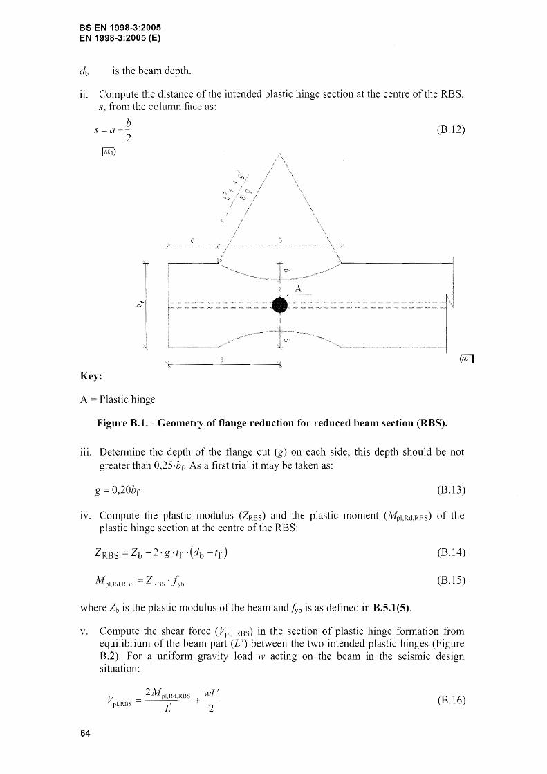
e distance between the plastic hinge and the column face
f~ concrete cOlupressive strength
f~t tensile strength of the concrete
IlIw tensile strength of the welds
yield strength of transverse reinforcen1ent
,h,p] n01111nal yield strength of each flange
12
lcp length of the cover plate
tep thickness of the cover plate
tf thickness
web thickness
W z panel-zone width between column ~''''',L.''''''''U
A g area of the section
Ahf area of the haunch flange
ApI area of each flange
Bs width of the steel flat-bar brace
B width of the COlTIposite section
E Young's modulus of the beam
elastic nlodulus of the RC (reinforced concrete) panel
F t seisnlic base shear
H frame height
He storey height of the fralne
K{p connection rotation stiffhess
1 lTIOlTIent of inertia
L bealTI span
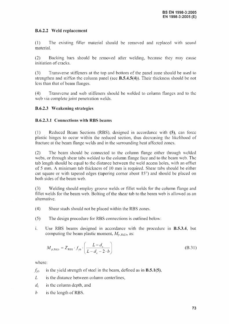
A1pb,Rd beam plastic nlonlent
Nd design axial
Ny yield strength of the steel brace
Sx beam elastic (n1ajor) modulus;
Tc thickness of the panel
Vpl,Rd,b shear force at a bean1 plastic hinge
Zb plastic modulus of the beanl
BS EN 1998-3:2005 EN 1998-3:2005 (E)
effective plastic lTIodulus of the section at the plastic hinge location
pw ratio of transverse reinforcement
1. 7 S.I. Units
(1) Reference is lTIade to EN 1998-1: 2004, 1.7.
13
BS EN 1998-3:2005 EN 1998-3:2005 (E)
2 PERFORl\1ANCE REQUIRE~fENTS AND COMPLIANCE CRITERIA
2.1 Fundamental requirements
(1)P The fundmnental requlrelnents refer to the state of danlage in the structure, herein defined through three Linlit States (LS), nalnely Near Collapse (NC), Significant Dall1age (SD), and Dalnage Limitation (DL). These Limit States shall be characterised as follows:
LS of Near Collapse (NC). The structure is heavily dall1aged, with low residual lateral strength and stiffness, although vertical elenlents are still capable of sustaining vertical loads. Most non-structural cOlnponents have col1apsed. Large pern1anent drifts are present. The structure is near collapse and would probably not survive another earthquake, even of moderate intensity.
LS of Significant Danlage (SD). The structure is significantly dan1aged, with son1e residual lateral strength and stiffness, and vertical elenlents are capable of sustaining vertical loads. Non-structural conlponents are dall1aged, although partitions and infills have not failed out-of-plane. Moderate pennanent drifts are present The structure can sustain after-shocks of nloderate intensity. The structure is likely to be unecono111ic to repaIr.
LS of Da111age Linlitation (DL). The structure is only lightly dan1aged, with structural elelnents prevented fron1 significant yielding and retaining their strength and stiffness properties. Non-structural components, such as partitions and infills, l11ay show distributed cracking, but the danlage could be economically repaired. Pennanent drifts are negligible. The structure does not need any repair Ineasures.
NOTE The definition of the Limit State of Collapse given in this Part 3 of Eurocode 8 is closer to the actual col1apse of the building than the one given in EN 1998-1: 2004 and corresponds to the fullest exploitation of the deformation capacity of the structural elements. The Limit State associated with the 'no collapse' requirement in EN 1998-1: 2004 is roughly equivalent to the one that is here defined as Limit State of Significant Damage.
(2)P The National Authorities decide whether all three Lin1it States shall be checked, or two of them, or just one of them.
NOTE The choice of ~ the Limit States to be checked in a country @1] , among the three Limit States defined in 2.1(1)P, may be found in the National Annex.
(3)P The appropriate levels of protection are achieved by selecting, for each of the Limit States, a return period for the seisn1ic action.
14
NOTE The return periods ascribed to the various Limit States to be checked in a country may be found in its National Annex. The protection normally considered appropriate for ordinary new buildings is considered to be achieved by selecting the following values for the return periods:
LS of Near Collapse (NC): 2.475 years, corresponding to a probability of exceedance of2% in 50 years
- LS of Significant Damage (SO): 475 years, corresponding 10 a probability of exceedance of 10% in 50 years LS of Damage Limitation (DL): 225 years, corresponding to a probability of exceedance of 20% in 50 years.
2.2 Compliance criteria
2.2.1 General
BS EN 1998-3:2005 EN 1998-3:2005 (E)
(I)P Compliance with the requirements in 2. t is achieved by adoption of the seisn1ic action, Inethod of analysis, verification and detailing procedures contained in this part of EN 1998, as appropriate for the ditIerent structural materials within its scope (i.e. concrete, steel, 111asonry).
(2)P Except when using the q-factor approach, compliance is checked by making use of the full (unreduced, elastic) SeiSll1ic action as defined in 2.1 and 4.2 for the appropriate return period.
(3)P For the verification of the structural elen1ents a distinction is n1ade between 'ductile' and 'brittle' ones. Except when using the q-factor approach, the forn1er shall be verified by checking that de111ands do not exceed the cOlTesponding capacities in te1111S of defonnations. The latter shall be verified by checking that den1ands do not exceed the corresponding capacities in tern1S of strengths.
NOTE Information for classifying components/mechanisms as "ductile" or "brittle" may be found in the relevant material-related Annexes.
(4)P Alternatively, a q-factor approach lnay be used, where use is made of a seismic action reduced by a q-factor, as indicated in 4.2(3)P. In safety verifications all structural elelnents shall be verified by checking that den1ands due to the reduced seisn11c action do not exceed the corresponding capacities in ter111S of strengths evaluated in accordance with (5) P.
(5)P For the calculation of the capacities of ductile or brittle elements, where these will be con1pared with den1ands for safety verifications in accordance with (3)P and (4)P, n1ean value properties of the existing materials sha11 be used as directly obtained from in-situ tests and fron1 the additional sources of inforn1ation, appropriately divided by the confidence factors defined in 3.5, accounting the level of knowledge attained. Nominal properties shall be used for new or added n1aterials.
(6)P Son1e of the existing structural elen1ents 111ay be designated as "secondary seisn1ic", in accordance with the definitions in EN 1998-1: 2004, 4.2.2 (1 )P, (2) and (3). "Secondary seis111ic" elen1ents shall be verified with the saIne conlpliance criteria as primary seisInic ones, but using less conservative estin1ates of their capacity than for the elelnents considered as "prin1ary seislnic".
(7)P In the calculation of strength capacities of brittle "prinlary seismic"elenlents, n1aterial strengths sha11 be divided by the partial factor of the material.
NOTE: The values ascribed to the partial factors for concrete, structural masonry and other materials for LIse in a country can be found in the National Annex to this standard. Notes to clauses 5.2.4(3), 6.1.3(1), 7.1.3(1) and 9.6(3) in EN1998-J: 2004 refer to the values of partial factors for steel, concrete, structural steel and masonry to be used for the design of new buildings in different countries.
2.2.2 Limit State of Near Collapse (NC)
(l)P Demands shall be based on the design seisnlic action relevant to this Lilnit State. For ductile and brittle elelnents delnands shall be evaluated based 011 the results
15
BS EN 1998-3:2005 EN 1998-3:2005 (E)
of the analysis. If a linear method of analysis is used, denlands on brittle elenlents shall be modified in accordance to 4.5.1 (1 )P.
(2)P Capacities shall be based on appropriately defined ultilnate defornlations for ductile elenlents and on ultin1ate strengths for brittle ones.
(3) The q-factor approach (see 2.2.1(4)P, 4.2(3)P) is generally not suitable for checking this Lin1it State.
NOTE The values of q = 1,5 and 2,0 quoted in 4.2(3)P for reinforced concrete and steel structures, respectively, as well as the values of q possibly justified with reference to the local and global available ductility in accordance with the relevant provisions of EN 1998-1: 2004, correspond to fulfilment of the Damage Limit State. If it is chosen 10 use this approach to check the Near Limit State, then 2.2.3(3)P may be with a value of the q-factor exceeding those in 4.2(3)P by about one-third.
2.2.3 Limit State of Significant Damage (SD)
(1 )P Denlands shall be based on the design selsn1ic action relevant to this LinTit State. For ductile and brittle elements denlands shall be evaluated based on the results of the analysis. In case a linear nlethod of analysis is used, detnands on brittle elenlents shal1 be n10dified in accordance to 4.5.1(1)P.
(2)P Except when using the q-factor approach, capacities shall be based on danlagerelated defonnations for ductile elelnents and on conservatively estimated strengths for brittle ones.
(3)P In the q-factor approach (see 2.2.1(4)P, 4.2(3)P), delnands shall be based on the reduced seisnlic action and capacities shall be evaluated as for non-seislnic design situations.
2.2.4 Limit State of Damage Limitation (DL)
(l)P Denlands shall be based on the design seismic action relevant to this Limit State.
(2)P Except when using the q-factor approach, capaCItIes shall be based on yield strengths for all structural elements, both ductile and brittle. Capacities of infil1s shall be based on mean interstorey drift capacity for the infills.
(3)P In the q-factor approach (see 2.2.1(4)P, 4.2(3)P), denlands and capacities shall be c0111pared in ternlS of nlean interstorey drift.
16
BS EN 1998·3:2005 EN 1998-3:2005 (E)
3 INFORMATION FOR STRUCTURAL ASSESSlVIENT
3.1 General information and history
(l)P In assessing the earthquake resistance of existing structures, the input data shall be col1ected from a variety of sources, including:
- available docun1entation specific to the building in question,
relevant data sources (e.g. contemporary codes and standards),
- field investigations and,
in nl0st cases, in-situ and/or laboratory measuren1ents and tests, as described 111
lTIOre detail in 3.2 and 3.4.
(2) Cross-checks should be made between the data collected from different sources to n1inilnise uncertainties.
3.2 Required input data
(I) In general, the infonnation for structural evaluation should cover the following points fron1 a) to i).
a) Identification of the structural systen1 and of its compliance with the regularity criteria in EN 1998-1: 2004, 4.2.3. The information should be collected either fron1 on site investigation or fronl original design drawings, if ava"ilable. In this latter case, infol111ation on possible structural changes since construction should also be collected.
b) Identification of the type of building foundations.
c) Identification of the ground conditions as categorised in EN 1998-1: 2004, 3.1.
d) I11fonllation about the overall din1ensions and cross-sectional properties of the building elenlents and the lnechanical properties and condition of constituent lnaterials.
e) Infol111atio11 about identifiable nlaterial defects and inadequate detailing.
f) Infornlation on the seismic design criteria used for the initial design, including the value of the force reduction factor (q-factor), if applicable.
g) Description of the present and/or the planned use of the building (with identification of its inlportance class, as described in 1998-1: 2004, 4.2.5).
h) Re-asseSSll1ent of in1posed actions taking into account the use of the building.
i) Infon11ation about the type and extent of previous and present structural dan1age, if any, including earlier repair l11easures.
(2)P Depending on the an10unt and quality of the inf01111ation collected on the points above, different types of analysis and different values of the confidence factors shall be adopted, as indicated in 3.3.
17
BS EN 1998-3:2005 EN 1998-3:2005 (E)
3.3 Knowledge levels
3.3.1 Definition of knowledge levels
(1) For the purpose of choosing the adlnissible type of analysis and the appropriate confidence factor values, the fo11owing three knowledge levels are defined:
KL I : Limited knowledge
KL2 : Nornlal knowledge
KL3 : Full knowledge
(2) The factors detennining the appropriate knowledge level (i.e.KL1, KL2 or KL3) are:
i) geomeuy: the geOlnetrical properties of the structural systeln, and of such nonstructural elenlents (e.g. nlasonry infill panels) as nlay affect structural response.
ii) details: these include the anlount and detailing of reinforcenlent in reinforced concrete, connections between 111embers, the connection of floor diaphragms to lateral resisting structure, the bond and nl0rtar jointing of nlasonry and the nature of any reinforcing elenlents in Inasonry,
jii) materials: the mechanical properties of the constituent materials.
(3) The knowledge level achieved detennines the allowable nlethod of analysis (see 4.4), as well as the values to be adopted for the confidence factors (CF). The procedures for obtaining the required data are given in 3.4.
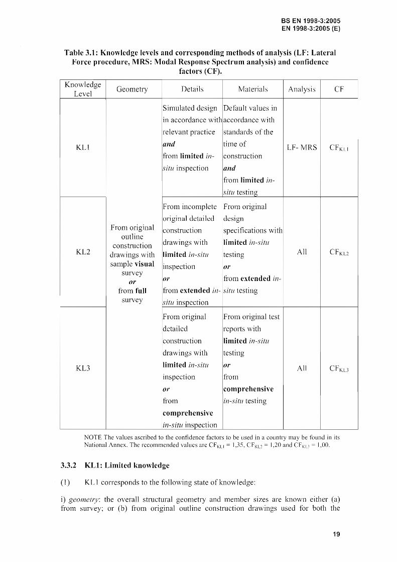
(4) The relationship between knowledge levels and applicable Inethods of analysis and confidence factors is illustrated in Table 3.1. The definitions of the terms 'visual', 'full', 'limited', 'extended' and 'cOlnprehensive' in the Table are given in 3.4.
18
BS EN 1998-3:2005 EN 1998-3:2005 (E)
Table 3.1: Knowledge levels and corresponding methods of analysis (LF: Lateral Force procedure, lVIRS: Modal Response Spectrum analysis) and confidence
factors (CF) .
. Knowledge GeOlnetry Details ]\Irateri al s Analysis CF
Level
Sinlulated design Default values in
in accordance wlthaccordance with
relevant practice standards of the
KLI and tilne of LF- MRS Icons tructi on fronl limited in-
situ inspection and
fronl limited in-
situ testing
From inconlplete F r0111 original
original detailed design Fronl original construction specifications with
outline construction drawings with .limited in-situ
KL2 drawings with limited il1-5;itll Itesting All
sanlple visual inspection PI' survey
fron1 extended in-or or
from full froln extended in- situ testing survey situ inspection
F rOln original FrOln original test
detailed reports with
construction limited in-situ
drawings with testing
I
KL3 limited in-situ or All CFKL3
inspection fro
or comprehensive
from in-situ testing
comprehensive
in-situ inspection
NOTE The values ascribed to the confidence factors to be used in a country may be found in its National Annex. The recommended values are CF KL1 = 1,35, CFKL2 = 1,20 and CFKL3 1,00.
3.3.2 KLl: Limited kno·wledge
(1) KL 1 corresponds to the following state of knowledge:
i) geo1Jwtly: the overall structural geonletry and melnber are known either (a) from survey; or (b) froln original outline construction drawings used for both the
19
BS EN 1998-3:2005 EN 1998-3:2005 (E)
original construction and any subsequent Inodifications. In case (b), a sufficient san1ple of dimensions of both overall geometry and n1en1ber sizes should be checked on site; if there are significant discrepancies fron1 the outline construction drawings, a fuller din1ensionaJ survey should be perfonned.
ii) details: the structural details are not known frOln detailed construction drawings and n1ay be assumed based on sin1ulated design in accordance with usual practice at the time of construction; in this case, limited inspections in the n10st critical elen1ents should be perfo1111ed to check that the assumptions conespond to the actual situation. Otherwise~ n10re extensive in-situ inspection is required.
iii) materials: no direct inforn1ation on the nlechanical properties of the construction ll1aterials is available, either fronl original design specifications or from Ol-jginal test reports. Default values should be assunled in accordance with standards at the tjnle of construction, accOlTIpanied by limited in-situ testing in the Inost critical elenlents.
(2) The inforn1ation collected should be sufticient for perforn1ing local verifications of element capacity and for setting up a linear structural analysis Inodel.
(3) Structural evaluation based on a state of limited knowledge should be perfornled through linear analysis methods, either static or dynamic (see 4.4).
3.3.3 KL2: Normal knowledge
(I) KL2 corresponds to the following state ofla10wledge:
i) geometr:v: the overall structural geon1etry and member sizes are known either (a) from an extended surveyor (b) from outline construction drawings used for both the original construction and any subsequent lTIodifications. In case (b), a sufficient sample of dinlensions of both overall ge0111etry and melYlber should be checked on site; if there are significant discrepancies from the outline construction drawings, a fuller dimensional survey is required.
ii) details: the structural details are known either frOlTI extended in-situ inspection or frOln inconlplete detailed construction drawings. In the latter case, liInited in-situ inspections in the 1110st critical elements should be perforn1ed to check that the available inforn1ation corresponds to the actual situation.
iii) materials: inforn1ation on the n1echanical properties of the construction Inaterials is available either fron1 extended in-situ testing or fron1 original design specifications. In this latter case, lin1ited in-situ testing should be performed.
(2) The inforn1ation collected should be sufficient for perfornling local verifications of elen1ent capacity and for setting up a linear or nonlinear structural model.
(3) Structural evaluation based on this state of knowledge ll1ay be perforn1ed through either linear or nonlinear analysis methods, either static or dynanlic (see 4.4).
3.3.4KL3: Full knowledge
(1) KL3 corresponds to the following state of knowledge:
i) geometry: the overall structural geon1etry and menlber sizes are known either (a)
20
BS EN 1998-3:2005 EN 1998-3:2005 (E)
from a conlprehensive survey or (b) fr01n the c0111plete set of outline construction drawings used for both the original construction and any subsequent nlodifications. [11
case (b), a sufficient saInple of both overall gemnetry and 111enlber sizes should be checked on site; jf there are significant discrepancies fro111 the outline construction drawings, a fuller dinlensional survey is required.
ii) detaiL)': the structural details are known either fr0111 comprehensive in-situ inspection or [f0111 a conlplete set of detailed construction drawings. In the latter case, linlited in-situ inspections in the 1nost critical elenlents should be performed to check that the available infornlation corresponds to the actual situation.
iii) materials: infornlation on the 111echanical properties of the construction nlaterials is available either frol11 comprehensive in-situ testing or fronl original test reports. In this latter case, lilnited in-situ testing should be performed.
(2) 3.3.3(2) applies.
(3) 3.3.3(3) applies.
3.4 Identification of the Knowledge Level
3.4.1 Geometry
3.4.1.1 Outline construction drawings
(1) The outline construction drawings are those docunlents that describe the geoll1etry of the structure, allowing for identification of structural c01nponents and their dimensions, as well as the structural systenl to resist both vertical and lateral actions.
3.4.1.2 Detailed construction dra\vings
(1) The detailed drawings are those docunlents that describe the geometry of the structure, allowing for identification of structural conlponents and their dinlensions, as well as the structural system to resist both vertical and lateral actions. In addition, they contain infomlation about details (as specified in 3.3.1(2)).
3.4.1.3 Visual survey
(1) A visual survey is a procedure for checking correspondence between the actual geometry of the structure with the available outline construction drawings. Sample geOlnetry Ineasurell1ents on selected elelnents should be carried out. Possible structural changes which Inay have occurred during or after construction should be subjected to a survey as in 3.4.1.4.
3.4.1.4 Full survey
(1) A full survey is a procedure resulting in the production of structural drawings that describe the gemnetry of the structure, allowing for identification of structural cOll1ponents and their dilnensions, as well as the structural systeln to resist both vertical and lateral actions.
21
BS EN 1998-3:2005 EN 1998-3:2005 (E)
3.4.2 Details
(1) Reliable non-destructive nlethods may be adopted in the inspections specified as follows:
3.4.2.1 Simulated design
(1) A sin1ulated design is a procedure resulting in the definition of the mnount and layout of reinforcenlent, both longitudinal and transverse, in all elements participating in the vertical and lateral resistance of the building. The design should be canied out based on regulatory docLlnlents and state of the practice used at the time of construction.
3.4.2.2 Limited in-situ inspection
(I) A l1111ited in-situ inspection is a procedure for checking correspondence between the actual details of the structure with either the available detailed construction drawings or the results of the sin1ulated design in 3.4.2.1. This entails perfornling inspections as indicated in 3.4.4(1 )P.
3.4.2.3 Extended in-situ inspection
(I) An extended in-situ inspection is a procedure used when the original detailed construction drawings are not available. This entails perfonning inspections as indicated in 3.4.4(1)P.
3.4.2.4 Comprehensive in-situ inspection
(1) A conlprehensive in-situ inspection is a procedure used when the original detailed construction drawings are not available and when a higher knowledge level is pursued. This entails perfonning inspections as indicated in 3.4.4(I)P.
3.4.3 1\1aterials
3.4.3.1 Destructive and non-destructive testing
(I) Use of non-destructive test methods (e.g., Schnlidt halnmer test, etc.) should be considered; however such tests should not be used in isolation, but only in conjunction with destructive tests.
3.4.3.2 Lhnited in-situ testing
(1) A lin1ited progranlnle of in-situ testing is a procedure for conlplenlenting the infofnlation on nlaterial properties derived either froll1 standards at the till1e of construction, or from original design specifications, or from original test reports. This entails perfoffi1ing tests as indicated in 3.4.4(1)P. However, if values fronl tests are lower than default values in accordance with standards of the time of construction, an extended in-situ testing is required.
3.4.3.3 Extended in-situ testing
(I) An extended progrmnn1e of in-situ testing is a procedure for obtaining infonnation when neither the original design specification nor the test reports are
22
BS EN 1998-3:2005 EN 1998-3:2005 (E)
available. This entails perfoll11ing tests as indicated in 3.4.4(1)P.
3.4.3.4 Comprehensive in-situ testing
(1) A con1prehensive progran1me of in-situ testing is a procedure for obtaining info1111ation when neither the original design specification nor the test reports are available and when a higher IG10wledge level is pursued. This entails performing tests as indicated in 3.4.4(l)P.
3.4.4 Definition of the levels of inspection and testing
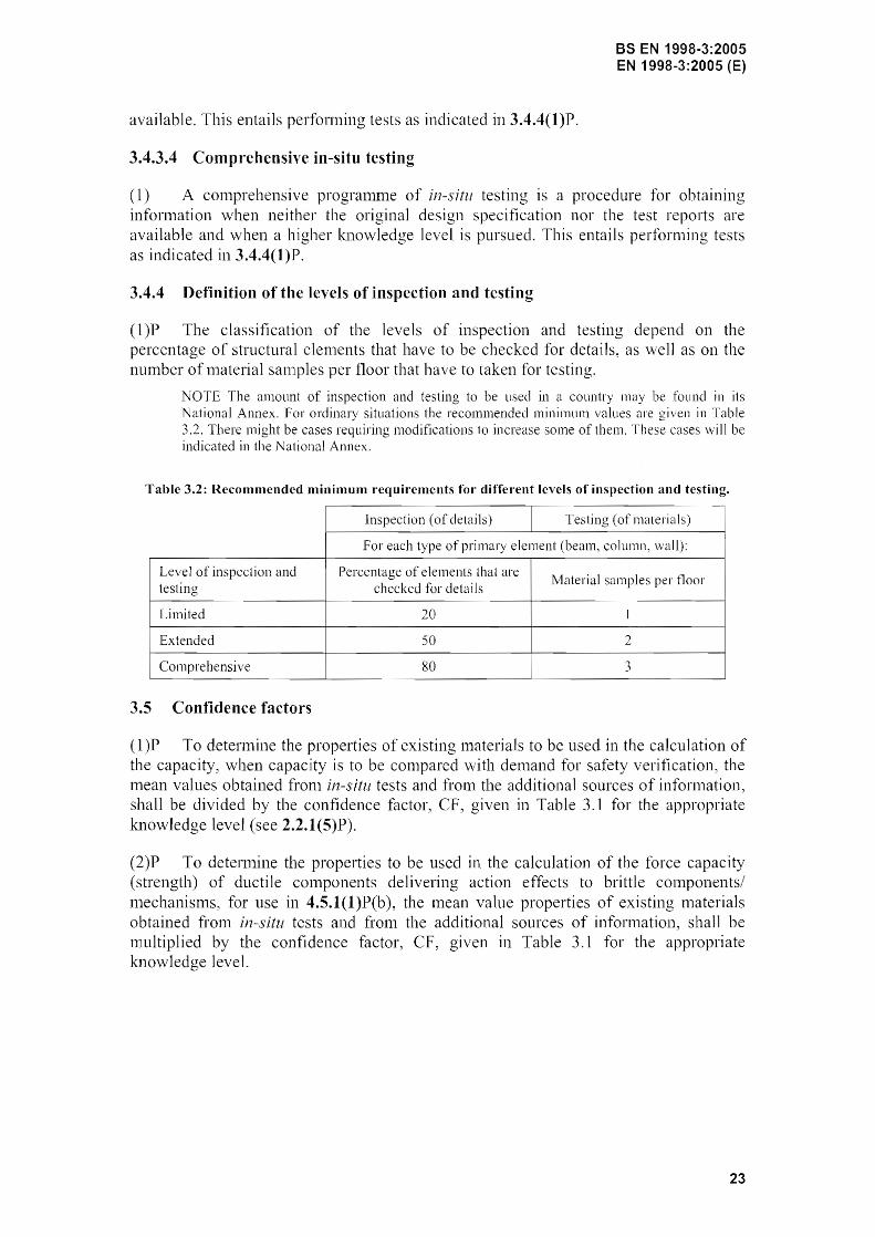
(l)P The classification of the levels of inspection and testing depend on the percentage of structural elen1ents that have to be checked for details, as we]] as on the number of n1aterial san1ples per floor that have to taken for testing.
NOTE The amollnt of inspection and testing to be used in a country may be found in its National Annex. For ordinary situations the recommended minimum values are in Table 3.2. There might be cases requiring modifications to increase some of them. These cases 'will be indicated in the National Annex.
Table 3.2: Recommended minimum requirements for diffel'ent levels of inspection and testing.
Inspection (of details) Testing (of materials) i
For each type of primary element (beam, column, wall): I
Level of inspection and Percentage of elements that are Material samples per floor
!
testing checked for details
Limited 20 1
. Extended 50 2
! Comprehensive 80 3
3.5 Confidence factors
(l)P To detennine the properties of existing Inaterials to be used in the ca1culation of the capacity, when capacity is to be compared with den1and for safety verification, the mean values obtained f1'o111 in-situ tests and fro111 the additional sources of inforIl1ation, shall be divided by the confidence factor, CF, given in Table 3.1 for the appropriate knowledge level (see 2.2.1(5)P).
(2)P To detennine the properties to be used in the calculation of the force capacity (strength) of ductile components delivering action effects to brittle cOlnponents/ ll1echanisms, for use in 4.5.1(1 )P(b), the n1ean value properties of existing 111aterials obtained fron1 in-situ tests and f1'o111 the additional sources of information, shall be multiplied by the confidence factor, CF, given in Table 3.1 for the appropriate knowledge level.
23
BS EN 1998-3:2005 EN 1998-3:2005 (E)
4 ASSESSMENT
4.1 General
(1) Assessn1ent is a quantitative procedure for checking whether an eXlstmg undanlaged or dmnaged building will satisfy the required lin1it state appropriate to the seisn1ic actio11 under consideration, as specified in 2.1.
(2)P This Standard is intended for the assessment of individual buildings, to decide on the need for structural intervention and to design the retrofitting 111easures that may be necessary. It is not intended for the vulnerability assessn1ent of populations or groups of buildings for seisnlic risk evaluation for various purposes (e.g. for detern1ining insurance risk, for setting risk mitigation priorities, etc.).
(3)P The assessment procedure shall be carried out by means of the general analysis methods specified in EN 1998-1: 2004, 4.3, as n10dified in this Standard to suit the specific problems encountered in the assessn1ent.
(4) Whenever possible, the Inethod used should incorporate information of the observed behaviour of the san1e type of building or similar buildings during previous earthquakes.
4.2 Seismic action and seismic load combination
(l)P The basic n10dels for the definition of the seisn1ic 1110tion are those presented in EN 1998-1: 2004, 3.2.2 and 3.2.3.
(2)P Reference is n1ade in particular to the elastic response spectrun1 specified in EN 1998-1: 2004, 3.2.2.2, scaled to the values of the design ground acceleration established for the verification of the different Lilnit States. The alten1ative representations allowed in EN 1998-1: 2004, 3.2.3 in tenns of either artificial or recorded accelerogrmns are also applicable.
(3)P In the q-factor approach (see 2.2.1(4)P), the design spectIun1 for linearanalysis is obtained fron1 EN 1998-1: 2004, 3.2.2.5. A value of q = 1,5 and 2,0 for reinforced concrete and steel stluctures, respectively, may be adopted regardless of the stIuctural type. Higher values of q may be adopted if suitably justified with reference to the local and global available ductility, evaluated in accordance with the relevant provisions of EN 1998-1: 2004.
(4)P The design seisnlic action shall be combined with the other appropriate permanent and variable actions in accordance with EN 1998-1: 2004, 3.2.4.
4.3 Structural modelling
(I)P Based on infonnation col1ected as indicated in 3.2, a lnodel of the structure shal I be set up. The Inodel shall be such that the action effects in all structural elen1ents can be detell11ined under the seislnic load cOlnbination given in 4.2.
(2)P All provisions of EN 1998-1: 2004 regarding nl0delling (EN 1998-1: 2004, 4.3.1) and accidental torsional effects (EN 1998-1: 2004, 4.3.2) shall be applied without
24
lTIodifications.
BS EN 1998-3:2005 EN 1998-3:2005 (E)
(3) The strength and the stiftlless of secondary seisll1ic elements, 2.2.1(6)P) against lateral actions nlay in general be neglected in the analysis.
(4) Taking into account secondaIY seisnlic elenlents in the overall structural model, however, is advisable if nonlinear analysis is applied. The choice of the elements to be considered as secondary seisn1ic may be varied after the results of a prelilninary analysis. In no case the selection of these elen1ents should be such as to change the classification of the struchIre fron1 non regular to regular, in accordance with the definitions in EN 1998-1: 2004, 4.2.3.
(5)P Mean values of n1aterial properties shall be used in the structuralluodel.
4.4 Methods of analysis
4.4.1 General
(1) The seist11ic action effects, to be combined with the effects of the other permanent and variable loads in accordance with the seisnlic load conlbination in 4.2( 4)P, may be evaluated using one of the following n1ethods:
lateral force analysis (linear),
- lTIodal response spectru111 analysis (linear),
- 11on-l inear static (pushover) analysis,
- non-linear tilDe history dyna111ic analysis.
- q-factor approach.
(2)P Except in the q-factor approach of 2.2.1(4)P and 4.2(3)P, the seislnic action to be used shall be the one conesponding to the elastic (i.e., un-reduced by the behaviour factor q) response spectrum in EN 1998-1: 2004, 3.2.2.2, or its equivalent alternative representations in EN 1998-l: 2004, 3.2.3.
(3)P In the q-factor approach of2.2.1(4)P the seislnic action is defined in 4.2(3)P.
(4) Clause 4.3.3.1(5) ofEN1998-1: 2004 applies.
(5) The above-listed methods of analysis are applicable subject to the conditions specified in 4.4.2 to 4.4.5, with the exception of n1asonry structures for which procedures accounting for the peculiarities of this construction typology need to be used.
NOTE Complementary information on these procedures may be found in the relevant materialrelated Informative Annex.
4.4.2 Lateral force analysis
(l)P conditions for this n1ethod to be applicable are given in EN 1998-1: 2004~ 4.3.3.2.1, with the addition of the following:
Denoting by D/Cj the ratio between the demand Di obtained fron1 the analysis
25
BS EN 1998-3:2005 EN 1998-3:2005 (E)
under the seisnlic load cOll1bination, and the corresponding capacity Cj for the i-tIl 'ductile' prinlary elenlent of the structure (bending monlent in n10ment fran1es or shear walls, axial force in a bracing~ of a braced fraIne, etc.) and by pmux and pmin the Inaximum and 111inimunl values of pi, respectively, over all 'ductile' prin1ary elelnents of the structure with Pi 1, the ratio Pmrj Pmin does not exceed a n1aximum acceptable value in the range of 2 to 3. Around bean1-colull1n joints the ratio Pi needs to be evaluated only at the sections where plastic hinges are expected to fo1'n1 on the basis of the c0111parison of the SU111 of bean1 flexural capacities to that of colUlllns. 4.3(5)P applies for the calculation of the capacities Ci. For the detel111ination of the bending nl0111ent capacities Cj of vertical elen1ents, the value of the axial force 111ay be taken eq ual to that due to the vertical loads only.
NOTE 1 The value ascribed to this limit of Pm;) x/ Pillill for lise in a country (within the range indicated above) may be found in its National Annex. The recommended value is 2,5.
NOTE 2 As an additional condition, the capacity C of the "brittle" elements or lllechanisl11sshould be larger than the corresponding demand D j , evaluated in accordance with 4.5.1 (I)P, (2) and (3). Nonetheless, enforcing it as a criterion for the applicability of linear analysis is redundant, because, in accordance with 2.2.2(2)P, 2.2.3(2)P and 2.2.4(2)P, this condition will ultimately be fulfilled in all elements of the assessed or retrofitted structure, irrespective of the mehod of
(2)P The method shall be applied as described in EN 1998-1: 2004, 4.3.3.2.2, 4.3.3.2.3 and 4.3.3.2.4, except that the ordinate of the response spectrunl in expression (4.5) shall be that of the elastic spectrunl Se(Td instead of the design spectrunl Sd(T1).
4.4.3 lVlulti-modal response spectrum analysis
(l)P The conditions of applicability for this ll1ethod are given in EN 1998-1: 2004, 4.3.3.3.1, with the addHion of the conditions specified in 4.4.2.
(2)P The method shall be applied as described in EN 1998-1: 2004, 4.3.3.3.2/3, using the elastic response spectrunl Se(TI).
4.4.4 Nonlinear static analysis
4.4.4.1 General
(1)P Nonlinear static (pushover) analysis is a non-linear static analysis under constant gravity loads and 1110110tonically increasing horizontal loads.
(2)P Buildings not conforming with the criteria of EN 1998-1: 2004, 4.3.3.4.2.1 (2), (3) for regularity in plan shall be analysed using a spatial nlodel.
(3)P For buildings confornling with the regularity criteria of EN 1998-1: 2004, 4.2.3.2 the analysis nlay be perforn1ed using two planar nl0dels, one for each n1ai11 horizontal direction of the building.
4.4.4.2 Lateral loads
(1) At least two vertical distributions of lateral loads should be applied:
26
a "uniforn1" pattern, based on lateral forces that are proportional to 111ass regardless of elevation (unifor111 response acceleration)
BS EN 1998~3:2005 EN 1998-3:2005 (E)
a "n10dar' pattern, proportional to lateral forces consistent with the lateral force distribution detern11ned in elastic analysis
(2) Lateral loads should be applied at the location of the masses In the 1110del. Accidental eccentricity should be taken into account.
4.4.4.3 Capacity curve
(1) The relation between base-shear force and the control displacement (the "capacity curve") should be detennined in accordance with 1998-1: 2004, 4.3.3.4.2.3(1), (2).
4.4.4.4 Target displacement
(l)P Target displacelnent is defined as in 1998-] : 2004, 4.3.3.4.2.6(1).
NOTE Target displacement may be determined in accordance with EN 1998-1: 2004, Informative Annex B.
4.4.4.5 Procedure for estimation of torsional and higher mode effects
(1)P The procedure given in EN 1998-1: 2004, 4.3.3.4.2.7(1) to (3) applies for the estimation of torsional effects.
(2) In buildings that do not meet the criteria in EN1998-1: 2004, 4.3.3.2.1 (2)a, the contributions to the response fron1 n10des of vibration higher than fundamental one in each principal direction should be taken into account.
NOTE The requirement in (2) may be satisfied either by performing a non-linear time-history analysis in accordance with 4.4.5, or through versions of the non-linear static analysis procedure that can capture the effects modes on global measures of the response (such as interslorey drifts) to be translated then to estimates of 10caJ deformation demands (such as member rotations). The National Annex may contain reference to complementary, noncontradictory information for sllch procedures.
4.4.5 Non-linear time-history analysis
(1)P The procedure given in EN 1998-1: 2004, 4.3.3.4.3(1) to (3) applies.
4.4.6 q-factor approach
(l)P In the q-factor approach, the method shall be applied as described in EN 1998-1: 2004, 4.3.3.2 or 4.3.3.3, as appropriate.
4.4.7 Combination of the components of the seismic action
(l)P two horizontal c0111ponents of the seismic action shall be c0111bined 111
accordance with EN 1998-1: 2004, 4.3.3.5.1.
(2)P The vertical con1ponent of the seismic action shall be taken into account In the cases specified in EN 1998-1: 2004, 4.3.3.5.2 and, when appropriate, con1bined with the horizontal cOlnponents as indicated in the san1e clause.
27
BS EN 1998~3:2005 EN 1998-3:2005 (E)
4.4.8 Additional measures for masonry infilled structures
(1) The provisions of EN 1998-1: 2004, 4.3.6 apply, wherever relevant.
4.4.9 Combination coefficients for variable actions
(l) The provisions of EN 1998-\: 2004, 4.2.4 apply
4.4.10 Inlportance classes and importance factors
(1) The provisions oLEN 1998-1: 2004,4.2.5 apply.
4.5 Safety verifications
4.5.1 Linear methods of analysis (lateral force or nlodal response spectrum analysis)
(l)P "'Brittle" components/mechanisnls shall be verified \vith denlands calculated by lneans of equilibriUln conditions, on the basis of the action effects delivered to the brittle component/nlechanism by the ductile conlponents. In this calculation, each action effect in a ductile cOlnponent delivered to the brittle con1ponent/n1echanism under consideration shall be taken equal to:
(a) the valueD obtained frOIU the analysis, if the capacity C of the ductile con1ponent, evaluated using mean values ofn1aterial properties, satisfies p = DIC ~ 1,
(b) the capacity of the ductile cOluponent, evaluated using nlean values of material properties l1lultiplied by the confidence factors, as defined in 3.5, accounting for the level of knowledge attained, if pD/C > 1, withD and C as defined in (a) above.
(2) In (1)b above the capacities of the beanl sections around concrete bealu-co1umn joints should be cOluputed froin expression (5.8) in 1998-1: 2004 and those of the colunln sections around such joints fron1 expression (5.9), using in the right-hand-side of these expressions the value /Rd = 1 and nlean values of material properties 111ultiplied by the confidence factors, as defined in 3.5.
(3) For the calculation of force dernands on the "brittle" shear luechanis11l of walls through (l)b above, expression (5.26) in EN 1998-1: 2004 nlay be applied with YRd 1 and using asMRd the bending monlent capacity at the base, evaluated using mea11 values of Inaterial properties ITIultiplied by the confidence factors, as defined in 3.5.
(4) In (l)P to (3) above the bending n1011lent capacities Ci of vertical elen1ents Inay be based on the value of the axial force due to the vertical loads only.
(5)P The value of the capacity of both ductile and brittle cOluponents and 11lechanis11ls to be con1pared to deluand in safety verifications, shall be in accordance with 2.2.1 (5)P.
NOTE Information for the evaluation of the capacity of components and mechanisms may be found in the relevant material related Informative Annexes Band C.
28
4.5.2 Nonlinear methods of analysis (static or dynamic)
BS EN 1998-3:2005 EN 1998-3:2005 (E)
(l)P The denlands on both "ductile" and "brittle" conlponents shall be those obtained frOlTI the analysis perfomled in accordance with 4.4.4 or 4.4.5, using 111ean value properties of the materials.
(2)P 4.5.1(5)P applies.
NOTE Information for the evaluation of the capacity of components and mechanisms may be found in the relevant material related Informative Annexes A, Band C.
4.5.3 q-factor approach
(l)P The values of both denland and capacity of ductile and brittle melTlbers shall be in accordance with 2.2.1(4)P, 2.2.3(3)P.
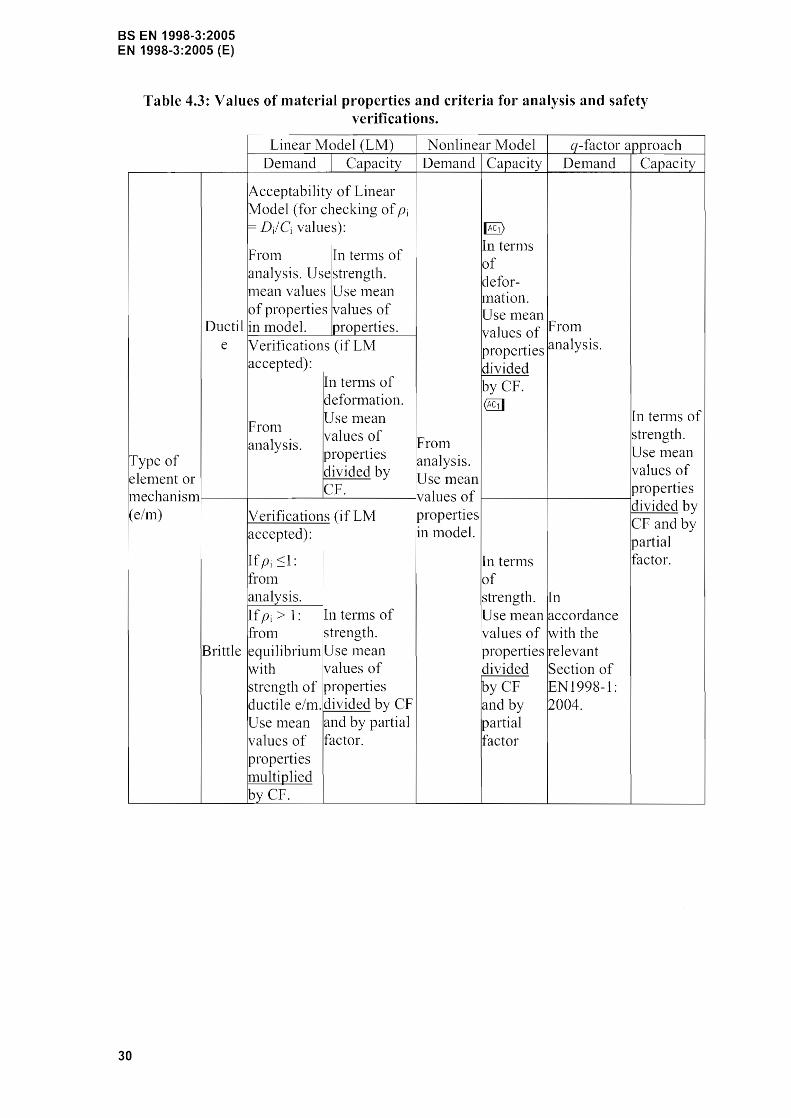
4.6 Summary of criteria for analysis and safety verifications
(l)P Table 4.3 sunlnlarises:
The values of the material properties to be adopted in evaluating both the denland and capacities of the elenlents for all types of analysis.
- The criterja that shall be followed for the safety verificatjon of both ductile and brittle elements for all types of analysis.
29
BS EN 1998-3:2005 EN 1998-3:2005 (E)
Table 4.3: Values of material properties and criteria for analysis and safety verifications.
Linear Model (LM) Nonlinear Model q-factor approach Den1and Capacity Den1and Capacity Delnand Capacity
•
Acceptability of Linear Model (for checking of Pi =- D/Cj values): I§)
Fronl lIn tenTIS of In ternlS of
analysis. Usestrength. defor-
111ean valuesU se nlean Ination. of properties values of Use nlean
Ducti1 in model, properties. values of From e Verifications (if LM properties analysis.
accepted): divided In ternlS of by CF. defonnation. 1@i1 Use mean In tenns of
Fronl values of strength.
analysis. From Type of properties analysis.
Use Inean
elenlent or divided by U: values of
Icp. ll1ean properties
lnechanislTI values of (elm) Verifications (if LM properties
divided by CF and by
accepted): in model. partial
If Pi In terms factor. fron1 of analysis. strength. In If Pi> 1: In terms of Use mean accordance fronl strength. !values of with the
Brittle equilibriull1!USe Inean properties ~elevant with values of idivided Section of strength of properties ~yCF IEN1998-1: ductile e/nl.ldivided by CF and by 2004. Use nlean and by partial partial values of factor. factor properties lTIultiplied byCF.
30
BS EN 1998-3:2005 EN 1998-3:2005 (E)
5 DECISIONS FOR STRUCTURAL INTERVENTION
5.1 Criteria for a structural intervention
5.1.1 Introduction
(1) On the basis of the conclusions of the asseSSlnent of the structure and/or the nature and extent of the dmnage, decisions should be taken for the intervention.
NOTE As in the of ne\-v structures, optimal decisions are pursued, taking into account social aspects, such as the disruption of use or occupancy during the intervention.
(2) Standard describes the technical aspects of the relevant criteria.
5.1.2 Technical criteria
(l)P The selection of the type, technique, extent and urgency of the intervention shall be based on the structural infon11ation collected during the asseSS111ent of the building.
(2) The following aspects should be taken into account:
a) All identified local gross errors should be appropriately relnedied;
b) In case of highly irregular buildings (both in tern1S of stiffness and overstrength distributions), structural regularity should be improved as much as possible, both In elevation and in plan;
c) The required characteristics of regularity and resistance can be achieved by ei ther 1110dification of the strength and/or stiffness of an appropriate l1u111ber of existing components, or by the introduction of new structuralelements;
d) Increase in the local ductility supply should be effected where required;
e) The increase in strength after the intervention should not reduce the available global ductility;
f) Speciflcally for nlasonry structures: non-ductile lintels should be replaced, inadequate connections between floor and wal1s should be ilnproved, out-of-plane horizontal thnlsts against walls should be eliminated.
5.1.3 Type of intervention
(1) An intervention may be selected from the following indicative types:
a) Local or overall tnodification of danlaged or undamaged elen1ents (repair, strengthening or full replacelnent), considering the stiffness, and/or ductility of these elements;
b) Addition of new structural elen1ents bracings or inft]] walls; steel, titl1ber or reinforced concrete belts in Inasonry construction; etc);
c) Modification of the structural systenl (eliInination of SOlne structural joints;
31
BS EN 1998-3:2005 EN 1998-3:2005 (E)
widening of joints; elinlination of vulnerable elenlents; nlodification into 1110re regular and/or nlore ductile arrangenlents) I;
d) Addition of a new structural systenl to sustain some or all of the entire seismic action;
e) Possible transfornlation of existing non-structural elenlents into structural elements;
f) Introduction of passive protection devices through either dissipative bracing or base isolation;
g) Mass reduction;
h) Restriction or change of use of the building;
i) Partial demolition;
(2) One or Inore types in cOlnbination may be selected. In all cases, the effect of structural nlodifications on the foundation should be taken into account.
(3)P If base isolation is adopted, the provisions contained in EN 1998-1: 2004, 10 sha11 be followed.
5.1.4 Non-structural elements
1 (P) Decisions regarding repair or strengthening of non-st1llctural elements shall also be taken whenever, in addition to functional requirenlents, the SeiS111ic behaviour of these elenlents may endanger the life of inhabitants or affect the value of goods stored in the building.
(2) In such cases, full or partial collapse of these elements should be avoided by nleans of:
a) Appropriate connections to structural elements (see EN 1998-1: 2004, 4.3.5);
b) Increasing the resistance of non-structural elelnents (see EN 1998-1: 2004, 4.3.5);
c) Taking measures of anchorage to prevent possible falling out of parts of these elelnents.
(3) The possible consequences of these provisions on the behaviour of structural elenlents should be taken into account.
5.1.5 Justification of the selected intervention type
(l)P In al1 cases, the documents relating to retrofit design shall include the justification of the type of intervention selected and the description of its expected effect on the structural response.
I This is for instance the case when vulnerable low shear-ratio columns or entire soft arc transformed into more ductile arrangements; similarly, when overstrength irregularities in elevation, or in-plan """<'111'-;1";1;,,<: are reduced by modifying the structural system.
32
(2) This justification should be made available to the owner.
BS EN 1998-3:2005 EN 1998-3:2005 (E)
33
BS EN 1998-3:2005 EN 1998-3:2005 (E)
6 DESIGN OF STRUCTURAL INTERVENTION
6.1 Retrotit design procedure
(I)P The retrofit design procedure shall include the following steps:
a) Conceptual design,
b) Analysis,
c) Verifications.
(2)P The conceptual design shall cover the following:
(i) Selection of techniques and/or materials, as well as of the type and configuration of the intervention.
(ii) Prelinlinary estinlation of dilTIensions of additional structural parts.
(iii) PrehlTIinary estilTIation of the lTIodified stiffness of the retrofitted elenlents.
(3)P The methods of analysis of the structure specified in 4.4 shall be used, taking into account the modified characteristics of the building.
(4)P Safety verifications shall be can-ied out in general in accordance with 4.5, for both existing, modified and new structural elements. For existing materials, nlean values from in-situ tests and any additional sources of information shall be used in the safety verification, nlodified by the confidence factor CF, as specified in 3.5. However, for new or added nlaterials nonlinal properties shaH be used, without modification by the confidence factor CF.
NOTE Information on the capacities of and new structural elements may be fOLlnd in the relevant material-related Informative Annex A, B or C.
(5)P In case the structural systeITI, comprising both eXIstIng and new stIuctural elenlents, can be made to fulfill the requirements of EN 1998-1: 2004, the verifications may be canied out in accordance with the provisions therein.
34
BS EN 1998-3:2005 EN 1998-3:2005 (E)
ANNEX A (Informative)
REINFORCED CONCRETE STRUCTURES
A.l Scope
(1) This Annex contains specific information for the assessment of reinforced concrete buildings in their present state, and for their upgrading, when necessary.
A.2 Identification of geometry, details and materials
A.2.1 General
(1) The fol1owing aspects should be carefully exanlined:
i. Physical condition of reinforced concrete elements and presence of any degradation, due to carbonation, steel corrosion, etc.
ii. Continuity of load paths between lateral resisting elelTIents.
A.2.2 Geometry
(1) The collected data should include the following itenls:
1. Identification of the lateral resisting systelTIS in both directions.
11. Orientation of one-way floor slabs.
111. Depth and width of beaITIS, COlUITInS and walls.
IV. Width of flanges in T -bealTIs.
V. Possible eccentricities between beams and colull1ns axes at joints.
A.2.3 Details
(1) The collected data should include the following iteiTIs:
1. Amount of longitudinal steel in beanls, colunlns and walls.
11. Anlount and detailing of confining steel in critical regions and in beanl-column joints.
111. AInount of steel reinforcement in floor slabs contributing to the negative resisting bending lTI01nent of T -bemus.
IV. Seating lengths and support conditions of horizontal elenlents.
35
BS EN 1998-3:2005 EN 1998-3:2005 (E)
v. Depth of concrete cover.
VI. Lap-splices for longltudinal reinforcel11ent.
A.2.4 Materials
(l) The collected data should include the following iten1s:
1. Concrete strength.
Steel yield strength, ultilnate strength and ultimate strain.
A.3 Capacity models for assessment
A.3. t Introduction
(I) The provisions given in this clause apply to both prin1ary and secondary seismic elenlents.
(2) Classification of con1ponents/n1echanislTIs:
1. "ductile": beaITI, colun1ns and walls under flexure with and without axial force,
11. "brittle": shear n1echanism of beams, colun1ns, walls and joints.
A.3.2 Beam, columns and walls under flexure with and without axial force
A.3.2.1 Introduction
(l) The deforInation capacity of bea111s, colU111ns and walls, to be verified in accordance with 2.2.2(2)P, 2.2.3(2)P, 2.2.4(2)P, is defined in tefnlS of the chord rotation (), i. e., of the angle between the tangent to the axis at the yielding end and the chord connecting that end with the end of the shear span (Lv M/V = n10n1ent/shear at the end section), , the point of contraflexure. The chord rotation is also equal to the element drift ratio, i. e., the deflection at the end of the shear span with respect to the tangent to the axis at the yielding end, divided by the shear span.
A.3.2.2 Limit State of near collapse (NC)
(l) The value of the total chord rotation capacity (elastic plus inelastic part) at ultinlate, eu , of concrete melnbers under cyclic loading may be calculated fr0111 the following expression:
=_1 0,016. (0,3 f,)[max(o,o 1; oj) ,rclO.225 r mil 9; Lv J' JO.35 2jap" II:" 1 (l,2 SllfO Po )
reI 111ax(O,O 1; OJ) \ 1\ h (A,1) @il
where:
rei is equal to 1,5 for prin1ary seislnic elenlents and to 1,0 for secondary seis111ic
36
BS EN 1998-3:2005 EN 1998-3:2005 (E)
elements (as defined in 2.2.1(6)P),
h is the depth of cross-section,
Lv = IV/IV is the ratio 1110n1ent/shear at the end section,
v N / b11f~ (b width of cOlupression zone, N axial force positlve for compression),
(j), (0' is the luechanical reinforcen1ent ratio of the tension (including the web reinforce111ent) and conlpression, respectively, longitudinal reinforcen1ent,
f~ and.hw are the concrete cOlnpressive strength (MPa) and the stirrup yield strength (MPa), respectively, directly obtained as Inean values fron1 in-situ tests, and froln the additional sources of 1nfo1'111ation, appropriately divided by the confidence factors, as defined in 3.5(1)P and Table 3.1, accounting for the level of knowledge attained,
psx ratio of transverse steel parallel to the direction x of loading (,')'/7
stirrup spacing),
Pd is the steel ratio of diagonal reinforcement (if any), in each diagonal direction,
a is the confinelnent effectiveness factor, that n1ay be taken equal to:
(A.2)
where:
bo and is the dimension of confined core to the centreline of the hoop,
bi is the centerline spacing of longitudinal bars (indexed by i) laterally restrained by a stinup conler or a cross-tie along the perin1eter of the cross-section.
In walls the value given by expression (A.1) is luultiplied by 0,58. @l]
If cold-worked brittle is used the total chord rotation capacity above is divided by 1,6.
(2) The value of the plas6c part of the chord rotation capacity of concrete n1en1bers under cyclic loading n1ay be calculated fronl the following expression:
where the chord rotation at yielding, By, should be calculated in accordance with A.3.2.4, reI is equal to 1,8 for primary seisluic elements and to 1,0 for secondary seismic ones and all other variables are defined as for expression (A.1), .
In walls the value given by expression (A.3) is ll1ultiplied by 0,6.
37
BS EN 1998-3:2005 EN 1998-3:2005 (E)
If cold-worked brittle steel is used, the plastic part of the chord rotation capacity is divided by 2.
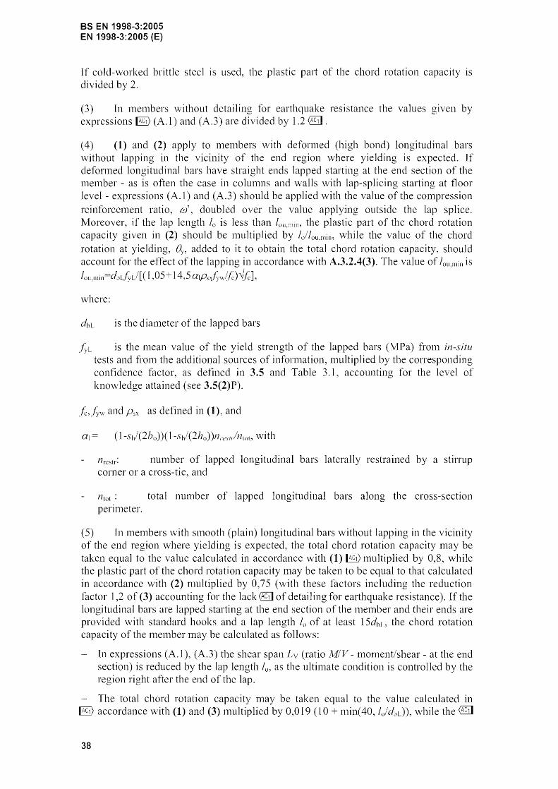
(3) In n1embers without detailing for earthquake resistance the values given by expressions ~ (A.l) and (A.3) are divided by 1.2 @j] .
(4) (1) and (2) apply to 111enlbers with defornled (high bond) longitudinal bars without lapping in the vicinity of the end region where yielding is expected. If deformed longitudinal bars have straight ends lapped starting at the end section of the Inen1ber - as is often the case in colunlns and walls with lap-splicing starting at floor level - expressions (A. 1 ) and (A.3) should be applied with the value of the conlpression reinforcenlent ratio, 0/ doubled over the value applyjng outside the lap splice. Moreover, if the lap length 10 is less than the plastic part of the chord rotation capacity given in (2) should be n1ultiplied by Ijlou.min, while the value of the chord rotation at yielding, added to it to obtain the total chord rotation capacity, should account for the effect of the lapping in accordance with A.3.2.4(3). The value of lou,min is
1,05+ 14,5 a'Psxlvw(fc)~fcJ,
where:
dbL is the dian1eter of the lapped bars
is the mean value of the yield strength of the lapped bars (NIPa) fr0111 in-situ tests and fron1 the additional sources of info1'n1atlon, n1ultiplied by the corresponding confidence factor, as defined in 3.5 and Table 3.1, accounting for the level of knowledge attained (see 3.5(2)P).
f~,f~\v and psx as defined in (1), and
nrcstr: number of lapped longitudinal bars laterally restrained by a stirrup corner or a cross-tie, and
11'01 : total l1unlber of lapped longitudinal bars along the cross-section perinleter.
(5) In 111enlbers with SI1100th (plain) longitudinal bars without lapping in the vicinity of the end region where yielding is expected, the total chord rotation capacity may be taken equal to the value calculated in accordance with (1) ~ 1111lltiplied by 0,8, while the plastic part of the chord rotation capacity 111ay be taken to be equal to that calculated in accordance with (2) multiplied by 0,75 (with these factors including the reduction factor l,2 of (3) accounting for the lack @j] of detailing for earthquake resistance). If the longitudinal bars are lapped starting at the end section of the n1en1ber and their ends are provided with standard hooks and a lap length 10 of at least 15dbL, the chord rotation capacity of the n1en1ber may be ca1culated as follows:
In expressions (A.!), (A.3) the shear span (ratio Jv!IV - tnoment/shear - at end section) is reduced by the lap length 10' as the ulti111ate condition is controlled by the region right after the end of the lap.
- The total chord rotation capacity nlay be taken equal to the value calculated in ~ accordance with (1) and (3) l11ultiplied by 0,019 (1 ° + n1in( 40, Ijdbd), while the @j]
38
BS EN 1998-3:2005 EN 1998-3:2005 (E)
plastic part of the chord rotation capacity Inay be taken equal to that calculated in ~ accordance with (2) and (3) multiplied by 0,019 mine 40, lo/dbd.
(6) For the evaluation of the ultinlate chord rotation capacity an alternative expression tnay be used:
Bum = 1
(AA) reI
\vhere
By is the chord rotation at yield as defined by expressions (A. 1 0) or (A. I I ),
¢u is the ultitnate curvature at the end section,
rA is the yield curvature at the end section.
The value of the length of the plastic hinge depends on how the enhancenlent of strength and deformation capacity of concrete due to confinelnent is taken into account in the calculation of the ultimate curvature of the end sectlon, rPu.
(7) If the ultimate curvature of the end section ¢u, under cyclic loading is calculated with:
(a) the ultimate strain of the longitudinal reinforcenlent, GSlh taken equal to:
- the nlininlU111 values given in EN 1992-1-1, Table C.I for the characteristic strain at nlaximUln force, Guk, for steel Classes A or B,
- 60/0 for steel Class C, and
(b) the confinenlent nlodeJ in EN 1992-1-1: 2004, 3.1.9, with effective lateral contlning stress 0"2 taken equal to apsx/~w, wbere psx,j~w and a have been defined in (1),
then, for nlembers with detailing for earthquake resistance and \vithout lapping of longitudinal bars in the vicinity of the section where yielding is expected, Lpl may calculated froIn the following expression:
Lpl O,lLv + 0,17 h + 0,24 ---;.===::- (A.S)
where h is the depth of the nlenlber and dbL is the (luean) dianleter of the tension reinforceluent.
(8) If the ultinlate curvature of the end section, ¢u, under cyclic loading is calculated with:
(a) the ultimate strain of the longitudinal reinforcenlent, Gsu, taken as in (7)a, and
(b) a confinenlent nl0del which represents better than the nl0del in EN 1992-1-1: 2004, 3.1.9 the ilnprovement of <Al with confinenlent under cyclic 10ading; nanlely a 1110del where:
39
BS EN 1998-3:2005 EN 1998-3:2005 (E)
the strength of confined concrete is evaluated fr01n:
J (A.6)
the strain at which the strength fcc takes place is taken to increase over the value £c2
of unconfined concrete as:
(A.7)
and the ultinlate strain of the extreme fibre of the cOlnpression zone is taken as:
8ClI
= 0,004 + (A.8)
where:
a, f~w and psx are as defined in (1) and (7) and is the concrete strength, as enhanced by confinement,
then, for members with detai1ing for earthquake resistance and no lapping of longitudinal bars near the section where yielding is expected, Lpl may be calculated fronl the following expression:
d f', (MPa) L = + 0,2h + O,ll----;bl='. '=J===-
pi 30 ~.r. (MPa) (A.9)
(9) If the confinenlent model in EN 1992-1-1: 2004 3.1.9 is adopted in the calculation of the ultilnate curvature of the end section, ~h and the value of fronl expression (A.S) is used in expression (AA), then the factor therein nlay be taken equal to 2 for prill1ary seisnlic and to 1,0 for secondary seislnic elements. If the cOnfine111ent nlodel given by expressions (A.6) to (A.8) is used instead, together with expression (A.9), then the value of the factor rei nlay be taken equal to 1,7 for prinlary SeiS111ic elelnents and to 1,0 for secondary seisnlic ones.
NOTE The values of the total chord rotation capacity calculated in accordance with (1) and (2) above (taking into account (3) to (5») are normally very similar. Expression (A.l) is more convenient when calculations and demands are based on total chord rotations, whilst expression (A.3) is better suited for those cases when calculations and demands are based on the plastic of chord rotations; moreover, (4) gives the chord rotation capacity of members with deformed longitudinal bars and straight ends lapped starting at the end section only in tenns of expression (A.3). Expression (A.4) with yields fairly similar results when used with either (7) or (8), but differences with the predictions of (1) or (2) are . The scatter of test results with respect to those of expression (A.4) for used with (8) is less than when it is used with (7). This is reflected in the different values of r",] specified in (I), (2) and (9), for primary seismic elements, as rei is meant to convert mean values to mean-minus-one-standard-deviation ones. Finally, the effects of lack of detailing for earthquake resistance and of lap splicing in the plasti hinge zone are specified in (3) to (5) only in connection with expressions (A.I) and (A.3).
(l0) Existing walls confornling to the definition of "large lightly reinforced wal1s" of
40
BS EN 1998-3:2005 EN 1998-3:2005 (E)
EN 1998-1: 2004, can be verified in accordance with EN 1992-1-1: 2004.
A.3.2.3 Limit State of Significant Damage (SD)
(1) The chord rotation capacity conesponding to significant damage eSD 111ay be assunled to be 3/4 of the ultilnate chord rotation au given in A.3.2.2.
A.3.2.4 Limit State of Damage Limitation (DL)
(1) The capacity for this li111it state used in the verifications is the yielding bending moment under the design value of the axial10ad.
(2) In case the verification is canied out in tenllS of defortl1ations the corresponding capacity is given by the chord rotation at yielding ay, evaluated as:
For beams and columns:
~ ay =9)' ___ z +0,OOI4(1+1,5~J+ , 3 Lv d-d
For walls of rectangular, or barbelled section:
~ ay - 9)' ---3
or from the alternative (and equivalent) expressions for bem11s and colUlnns:
~a y 91: --3-
Z + 0,0014(1 + 1,5 h + ¢1. db/;-@il
. Lv . 8.vfc
and for walls of rectangular, T - or barbelled section:
~a.), =9,), ___ z +00013+9 dbL f r @1] 3 ' )' 8[[
where:
<A is the yield curvature of the end section,
(A. 1 Oa)
(A.Ila)
(A.IOb)
(A.llb)
~ayz@1]is the tension shift of the bending nlonlent diagral11 (see EN 1992-1-1: 2004, 9.2.1.3(2)), with
Z length of internal lever ann, taken equal to d-d' in beanls, C01U1l1nS, or walls with barbelled or T -section, or to 0,811 in walls with rectangular section, and
~ ay= 1 if shear cracking is expected to precede flexural yielding at the end section (i.e. when the yield mOlllent at the end section, A1y, exceeds the product of Lv tinles the shear resistance of the nlenlber considered without shear reinforceillent, VR,c, taken in accordance with 1992-1 1: 2004, 6.2.2(1)); otherwise, (i.e. ifMy<Lv VR,c) ay=O, @1]
41
BS EN 1998-3:2005 EN 1998-3:2005 (E)
/~ and.t~ are the steel yield stress and the concrete strength~ respectively, as defined for expression (A.l), both in MPa,
Ill' is equal to// Es,
d and d' are the depths to the tension and COll1preSSlon reinforcen1ent, respectively, and
dbL is the (lnean) dianlcter of the tension reinforcement.
The first term in expressions CA. 1 0), (A.Il) accounts for the flexural contribution. The second tenn represents the contribution of shear deforn1ation and the third anchorage slip of bars.
NOTE The two alternative sets of expressions: (A. lOa), (A.11a) on one hand and (A.l Ob), (A. 1] b) on the other are practically equiv·alent. Expressions: lOa), (A.! la) are more rational but expressions: (A.1 Ob), (A. 11 b) are more convenient and their llse may be overall more convenient, as the calculation of ¢y may be dit1icult and more prone to errors.
(3) (1) and (2) apply to members with longitudinal bars without lapping in the vicinity of the end region where yielding is expected. If longitudinal bars are deforn1ed with straight ends lapped starting at the end section of the lnember (as in colUlnns and walls with lap-splicing starting at floor level), the yield monlentA1y and the yield
curvature in expressions (A. 1 0), (A. II ) should be conlputed with a c0111pression reinforcement ratio doubled over the value applying outside the lap splice. If the straight Jap length 10 is less than loy.min=0,3dblf~L/~fc, where dbL is the diameter of the lapped bars, .f~L (in MPa) is the lnean value of the steel yield strength of Japped bars from in-situ tests and fron1 the additional sources of information, 1nultiplied by the confidence factor, as defined in 3.5 and Table 3.1, accounting for the level of knowledge attained (see 3.5(2)P) and (in MPa) is as defined for expression (A.l), then:
- My and (A should be calculated with the yield stress,,!;:, nlultiplied by lolloy,min,
the yield strain, Ily, in the last term of expressions (A. lOa), (A.11a) should be nlultiplied by lo/loy,min,
- the second tenl1 in expressions (A. 1 0), (A. II ) should be ll1ultiplied by the ratio of the value of yield InOlnent 1\11y as nlodified to account for the lap splicing, to the yieldmOlnent outside the lap splice,
- in order to deternline whether tenn avz contributes to the first tenn in expressions
CA.IO), (A. I I ) with av= 1, the product Lv VR,c is con1pared to the yield mOlnent }dy
as 1110dified for the effect of the lapping.
(4) (I) and (2) 111ay be considered to apply also to Inembers with s11100th longitudinal bars, even when their ends, supplied with standard hooks, are lapped starting at the end section of the nlember (as in colunlns and walls with lap-splicing starting at floor level), provided that the lap length 10 is at least equal to 15dbL•
(5) If the verification is carried out in ternlS of defonl1ations, defornlation den1ands should be obtained frOIn an analysis of a stluctural1nodel in which the stiffness of each
elenlent is taken to be equal to the mean value of MyL y/3 By, at the two ends of the elenlent. In this calculation the shear span at the end section, Lv, n1ay be taken to be equal to half the ele1nent length.
42
A.3.3 Beams, columns and walls: shear
A.3.3.1 Limit State of Near Collapse (NC)
BS EN 1998-3:2005 EN 1998-3:2005 (E)
(1) The cyclic shear resistance, VR, decreases with the plastic part of ductility demand, expressed in terms of ductility factor of the transverse deflection of the shear span or of the chord rotation at 111ember end: fitc,pl= f-ltc,-l. For this purpose f-l(j.pj may be calculated as the ratio the plastic part of the chord rotation, 8, normalized to the chord rotation at yielding, By, calculated in accordance with A.3.2.4(2) to (4).
The following expression Inay be used for the shear strength, as controlled by the stirrups, accounting for the above reduction (with units:MN and meters):
{0,16maX(0,5; 100PloI {1-O,16 h J)ff A, + V" JJ (A.12)
where:
ret is equal to 1,15 for prinlary seisnlic elenlents and 1,0 for secondary SelS1111C elements (as defined in 2.2.1(6)P),
h is the depth of cross-section (equal to the dianleter D for circular sections),
x is the cOlnpression zone depth,
N is the compressive axial force (positive, taken as being zero tension ),
Lv M/V is the ratio moment/shear at the end section,
Ae is the cross-section area, taken as being equal to bwd for a cross-section with a rectangular web of width (thickness) bw and structural depth d, or to (where Dc = D-2c-2dbvi , is the dianleter of the concrete core to the inside of the hoops, with D and c as defined in b) below and dbw the dial11eter of the transverse reinforcement) for circular sections,
is the concrete compressive strength, as defined for expression (A. 1 ); for primary seismic elelnents j~ should further be divided by the partial factor for concrete in accordance \vith EN 1998-1: 2004, 5.2.4,
Plot is the total longitudinal reinforcement ratio,
Vw is the contribution of transverse reinforcenlent to shear resistance, taken as being equal to:
a) for cross-sections with rectangular web of width (thickness) bw :
(A.13)
where:
P"v is the transverse reinforcelnent ratio,
43
BS EN 1998-3:2005 EN 1998-3:2005 (E)
.::.. is the length of the inten1al lever arm, as specified in A.3.2.4(2), and
is the yield stress of the transverse reinforcen1ent as defined for expression (A. 1 ); for prin1ary seisnlic elenlents should further be divided by the partial factor for steel in accordance with EN 1998-1: 2004, 5.2.4;
b) for circular cross-sections:
where:
D is the diaIneter of the section,
Asw is the cross-sectional area of a circular stirrup,
s is the centerline spacing of stirnlps,
is as defined in (a) above, and
c is the concrete cover.
(A.14)
(2) The shear strength of a concrete wall, VR, n1ay not be taken greater than the value corresponding to failure by web crushing, VR,max, which under cyclic loading may be calculated fron1 the following expression (with units: MN and meters):
where reI 1,15 for primary seislnic elements and 1,0 for secondary seis111ic ones, j~ is in MPa, bw and z are in lneters and VR,m3x in MN, and all other variables are as defined in (1).
The shear strength under cyclic loading as controlled by web crushing prior to flexural yielding is obtained frOln expression (A. IS) for .u~pl=O.
(3) If in a concrete colulnn the shear span ratio, Lylh, at the end section with the ll1axin1um of the two end n10ments less or equal to 2,0, its shear strength, VR, should not be taken greater than the value corresponding to failure by web crushing along the diagonal of the colun1n after flexural yielding, VR,max, which under cyclic loading may be calculated from the expression (with units: MN and meters):
where:
(j is the angle between the diagonal and the axis of the colulnn (tan(j =hI2L y ),
and all other variables are as defined in (3).
(4) The nlinill1ull1 of the shear resistance calculated in accordance with EN 1992-1-1: 2004 or by means of expressions (A.12)-(A.I6) should be used in the assessment.
(5) Mean nlaterial properties fron1 in-situ tests and froln additional sources of
44
BS EN 1998-3:2005 EN 1998-3:2005 (E)
inforn1ation, should be used in the calculations.
(6) For primary seismic eleillents, mean n1aterial strengths in addition to being divided by the appropriate confidence factors based on the Kno\vledge Level, they should be divided by. the partial factors for materials in accordance with 1998-1: 2004, 5.2.4.
A.3.3.2 Limit State of Significant Damage (SD) and of Damage Linlitation (DL)
(1) The verification against the exceedance these two LS is not required, unless these two LS are the only ones to be checked. In that case A.3.3.1 applies.
A.3.4 Beam-column joints
A.3.4.1 LS of Near Collapse (NC)
(1) The shear del11and on the joints is evaluated in accordance with 1998-1 : 2004,5.5.2.3.
(2) The shear capacity of the joints is evaluated in accordance with EN 1998-1: 2004, 5.5.3.3.
(3) A.3.3.1(5) and (6) apply to joints of primary seIsmIC elements with other elements,
A.3.4.2 Limit State of Significant Damage (SD) and of Damage Limitation (DL)
(1) The verification against the exceedance of these two LS is not required, unless these two LS are the only ones to be checked. In that case, A.3.4.1 applies.
A.4 Capacity models for strengthening
A.4.1 General
(1) The rules for member strength and defonnation capacities given in the following clauses for strengthened l11embers refer to the capacities at the LS of NC in A.3.2.2 and A.3.3.1 prior to the application of the overall factor reI. The factors specified in A.3.2.2 and A.3.3.1 should be applied on the strength and deforn1ation capacities of the retrofitted member, as detern1ined in accordance with the following clauses.
(2) The partial factors to be applied to the new steel and concrete used for the retrofitting are those of EN 1998-1: 2004, 5.2.4, and to new structural steel used for the retrofitting are those ofEN1998-1: 2004, 6.1.3(1)P.
A.4.2 Concrete jacketing
A.4.2.1 Introduction
(1) Concrete jackets are applied to colunu1s and walls for all or son1e of the
45
BS EN 1998-3:2005 EN 1998-3:2005 (E)
following purposes:
increasing the bearing capacity,
increasing the flexural and/or shear strength,
- increasing the deformation capacity,
inlproving the strength of deficient lap-splices.
(2) The thickness of the jackets should allow for p]acelnent of both longitudinal and transverse reinforcenlent with an adequate cover.
(3) When jackets aim at increasing flexural strength, longitudinal bars should be continued to the adjacent storey through holes piercing the slab, while horizontal ties should be placed in the joint region through horizontal holes drilled in the beams. Inay be Olnitted in the case of fully confined interior joints.
(4) \Vhen only shear strength and defornlation capacity increases are of concern, jointly with a possible improvenlent of lap-splicing, then jackets should be tenllinated (both concreting and reinforcement) leaving a gap with a slab of the order of 10 Innl.
A.4.2.2 Enhancement of strength, stiffness and deformation capacity
(1) For the purpose of evaluating strength and defofnlation capacities of jacketed elenlents, the following approxinlate sinlplifying aSSulllptions nlay be made:
- the jacketed elenlent behaves Inonolithically, with full composite action between old and new concrete,
the fact that axial load is originally applied to the old colUlnn alone is disregarded, and the full axial load is assumed to act on the jacketed elelnent,
- the concrete properties of the jacket are assumed to apply over the full section of the elenlent.
(2) The following relations may be assumed to hold between the values of V[{, Niy,
ey, and eu, calculated under the assmnptions above and the values VR * ,A1y *, ey*, and ~I* to be adopted in the capacity verlfications:
- For VR* :
(A. I?)
For M.y*:
(A.18)
IRi) Text deleted
= 1,05 (A.l9a)
46
IEl) Text deleted @11
- For Bu*:
Bu* =Bu
BS EN 1998-3:2005 EN 1998~3:2005 (E)
(A.20)
(3) The values of ~l*' By *, A1y* of the jacketed nlell1ber, to be used in conlparisolls to demands in safety verifications, should be cOinputed on the basis of: (a) the n1eall value strength of the existing steel as directly obtained fronl in-situ tests and from additional sources of inforn1ation, appropriately divided by the confidence factor in 3.5, accounting for the level of knovvledge attained; and (b) the non1inal strength of the added concrete and reinforcetnent.
(4) The value of Vj<* of the jacketed member, to be conlpared to the demand in safety verifications, should be cOlnputed on the basis of: (a) the Jl1ean value strength of the existing steel as directly obtained fr0111 in-situ tests and fro111 the additional sources of infornlation, divided by the appropriate confidence factor in 3.5, accounting for the level of knowledge attained; and (b) the n0111ina] strength of the added concrete and reinforcement. In prinlary SeiS111ic elements the nlean value strength of the existing steel and the nominal strength of the added materials should be divided by the partial factors for steel and concrete in accordance with EN 1998-1: 2004, 5.2.4.
(5) The value of My * of jacketed nlen1bers that deliver action effects to brittle con1ponents/nlechanis111s, for use in 4.5.1(1)P(b), should be COl1lputed on the basis of: (a) the 11lean value strength of the existing steel as directly obtained fron1 in-situ tests, and froll1 additional sources of illfo1111atioll, appropriately nlu1tiplied by the confidence factor in 3.5, accounting for the level of knowledge attained; and (b) the 110111inal strength of the added concrete and reinforcement(see 3.5(2)P).
A.4.3 Steel jacketing
A.4.3.1 Introduction
(1) Steel jackets are Inainly applied to colulnns for the purpose of: increasing shear strength and improving the strength of deficient lap-splices. They n1ay also be considered to increase ductility through confinement.
(2) Steel jackets around rectangular colulnns are usual1y built up of four corner angles to which either continuous steel plates, or thicker discrete horizontal steel straps, are welded. C0111er angles nlay be epoxy-bonded to the concrete, or just made to adhere to it without gaps along the entire height. Straps n1ay be pre-heated just prior to welding, ill order to provide afterwards some positive confinel11ent on the COlUI1111.
A.4.3.2 Shear strength
(1) The contribution of the jacket to shear strength lTIay be assul11ed as addjtive to existing strength, provided the jacket renlains well within the elastic range. This
47
BS EN 1998-3:2005 EN 1998-3:2005 (E)
condition is necessary for the jacket to be able to control the width of internal cracks and to ensure the integrity of the concrete, thus allowing the original shear resisting mechanism to continue to operate.
(2) If only 50?lo of the steel yield strength of the jacket is used, the expression for the additional shear V:i carried by the jacket
~V= J
. (cot B + cot fJ)· sin fJ (A.21)
where:
h is the depth of the cross-section,
t is the thickness of the steel straps, J
b is the width of the steel straps,
s is the spacing of the steel straps (b/s 1, in case of continuous steel plates),
e is the strut inc lination angle,
fJ is the angle between the axis of the steel straps and the axis of the ll1eluber 90°, in case of continuous steel plates), and
f~j,d is the design yield strength of the steel of the jacket, equal to its nOlTIinal strength divided by the partial factor for structural steel in accordance with EN 1998-1: 2004, 6.1.3(1)P.
A.4.3.3 Clamping of lap-splices
(1) Steel jackets can provide effective c1atnping in the regions of lap-splices, to improve cyclic deformation capacity. For this result to be obtained the following is necessary:
- the length of the jacket exceeds by no than 50% the length of the splice region,
- the jacket is pressured against the faces of the colUlnn by at least two rows of bolts on each side normal to the direction of loading,
when splicing occurs at the base of the COlUll111, the rows of bolts should be located one at the top of the splice region and another at 113 of that region, starting froll1 the base.
A.4.4FRP plating and wrapping
A.4.4.1 Introduction
(1) The nlain uses of externally bonded FRP (fibre-reinforced polynlers) in seismic retrofitting of existing reinforced concrete elenlents are as follows:
Enhancenlent of the shear capacity of colunlns and walls, by applying externally bonded FRP with the fibers in the hoop direction,
Enhancenlent of the available ductility at nlenlber ends, through added confinement in the forn1 of FRP jackets, with the fibres oriented along the perinleter,
Prevention of lap splice failure, through increased lap confinenlent again with the fibers along the perinleter.
(2) The effect of FRP plating and wrapping of n1en1bers on the flexural resistance of the end section and on the value of the chord rotation at yielding, By, nlay be neglected
48
BS EN 1998-3:2005 EN 1998-3:2005 (E)
({}y may be con1puted in accordance with A.3.2.4(2) to (4), with foy,mill taken equal to 0,2dblf~L/~f~, in A.3.2.4( 4»).
A.4.4.2 Shear strength
(1) Shear capacity of brittle conlponents can be enhanced in beams, columns or shear walls through the application of FRP strips or sheets. These nlay be applied either by fully wrapping the or by bonding thenl to the sides and the soffit of the beam (U-shaped strip or or by bonding thenl to the sides only.
(2) The total capacity, as controlled by the StilTUPS and the FRP, is evaluated as the sunl of one contribution fron1 the existing concrete nlenlber, evaluated 111
accordance with EN 1998-1: 2004 and another contribution, from the FRP.
(3) The total shear capacity nlay not be taken greater than the Il1axinlunl shear resistance of the concrete nlelnber, VR,max, as controlled by diagonal compression in the web. The value of VR.m3x nlay be calculated in accordance with EN1 992-1-1: 2004. For concrete walls and for colunlns with shear span ratio, Lv/h, less or equal to the value of VR.max is the 111inil11U111 of the value in accordance vvith EN 1992-1-1: 2004 and of the value calculated fron1 A.3.3.1(2) and A.3.3.1(3), respectively, under inelastic cyclic loading.
(4) For nlelnbers with rectangular section, the FRP contribution to shear capacity may be evaluated as:
- for full wrapping with FRP, or for U-shaped FRP strips or sheets,
VRd,f = 0,9 d . ffdd.e ·2· t f . . (cot {} + cot jJ) . sin jJ (A.22)
- for side bonded FRP strips or sheets as:
VRd,f = 0,9 d . . 2 . t . sin jJ . W f f . {} SIn Sf
(A.23)
where:
d is the effective depth,
{} is the strut inclination angle,
ff'dd,c is the design FRP debonding strength, which depends on strengthening configuration in accordance with (5) for fully wrapped FRP, or (6) for U-shaped FRP, or (7) for side bonded FRP,
tf is the thickness of the FRP strip, sheet or fabri c (on single side),
f3 is the angle bet\veen the (strong) fibre direction in the FRP strip, sheet or fabric and the axis of the Inen1ber,
WI' is the width of the FRP strip or sheet, nleasured orthogonally to the (strong) direction of the fibres (for sheets: min(O,9d,h
ll.)· sin(B+ {J)/sinB) and
Sf is the spacing of FRP strips "VI' for sheets), n1easured orthogonally to the
49
BS EN 1998-3:2005 EN 1998-3:2005 (E)
(strong) fibre direction.
(5) For fully wrapped (i.e., closed) or properly anchored (in the conJpression zone) jackets, the design FRP effective debonding strength l11ay be taken in expressions (A.22), (A.23) as:
(A.24)
where:
z = 0,9d is the internal lever ann,
2 , and:
f · 1 0,6 Ef f~tm kb . fdd =-
rfd If (units: N, 1111n) (A.25)
1s the design debonding strength, with:
/i'Ll the partial factor for FRP debonding,
NOTE The value ascribed 10 hd for use in a country can be found in its National Annex. The recommended value is
Er the FRP sheets/plates 1TIodulus,
f~tm the concrete mean tensile strength,
the covering coefficient,
in which:
are as defined in (4) and
fru,w(R) is the ultimate strength of the FRP strip or sheet wrapped around the corner with a radius R, given by:
(R) = f~ad \YJR' f~lI - ffdd) (A.26)
,vhere the ten11 in (.) should be taken only if positive and where the coefficient 77R
depends on the rounding radius R and the beam width byv as:
R 17R = 0,2 + 1,6-
b\v
Lc is the effective bond length:
with:
Ef ·tf
~4.rmax (units: N, mn1)
T;nax = 1 ,~j~tn,l(b nlaxinlunl bond strength.
50
(A.27)
(A.28)
BS EN 1998-3:2005 EN 1998-3:2005 (E)
(6) For U-shaped (i.e., open) jackets, the design FRP effective debonding strength may be taken in expressions (A.22) and (A.23) as:
[ Le sin 13]
ffdd,e,U = ff'dd' l-k Z (A.29)
where all variables are as defined in (5).
(7) F or side-bonded sheets/strips, the design FRP effective debonding strength n1ay be taken in expressions (A.22), (A.23) as:
ffdd,e,S = ffdd ' Zri~eq , [1- k Leq J2 Zrid,eq
where:
Zrid,eq = Zrid + L eq , Zrid = Z - Le . sin 13,
with:
crdd = frdd/Er, and
til = kb /3.
(A.30)
Uj . 13 Leg =--'Sln
cfdd (A.31 )
(8) For lnembers with circular section having dialneter D, the FRP contribution is evaluated as:
(A.32)
where:
Ac is the colUlnn cross-section area,
PI' is equal to 4 tf / D is the volun1etric ratio of the FRP, and
Cf,cd = 0,004.
(9) In n1en1bers with their plastic hinge region fully wrapped in an FRP jacket over a length at least equal to the melnber depth h, the cyclic shear resistance, VI{, n1ay be taken to decrease with the plastic part of the chord rotation ductility den1and at the men1ber end: P6.P1= JL6.-1, in accordance with expression (A.12), adding to Vw (i.e. to the contribution of transverse reinforcement to shear resistance) that of the FRP jacket. The contribution of the FRP jacket to Vw may be computed assun1ing that the FRP stress reaches the design value of the FRP ultimate strength;f~l,ja, at the extren1e tension fibres and reduces linearly to zero over the effective depth d:
(A.33)
where:
pr equal to 2ff /bw is the geon1etric ratio of the FRP,
z is the length of the inten1al1ever ann, taken equa1 to d, and
f~lJd is the design value of the FRP ultilnate strength, equal to the FRP ultimate
51
BS EN 1998-3:2005 EN 1998-3:2005 (E)
strength'/l,fdivided by the partial factor )1(1 of the FRP,
NOTE The valLIe ascribed to }lei for LIse in a country can be found in its National Annex. The recommended value is ,5.
A.4.4.3 Confinement action
(1) The enhancenlent of defornlation capacity is achieved through concrete confinelnent by means of FRP jackets. These are applied around the e]elnent to be strengthened in the potential plastic hinge region.
(2) The necessary mnount of confinelnent pressure to be applied depends on the ratio Ix Jl(I),tari Jl(II,aVa, between the target curvature ductility JlQJar and the available curvature ductility and nlay be evaluated as:
(A.34)
where:
.!c is the concrete strength, defined as for expression (A. 1 ),
Bell is the concrete ultimate strain, and
t'ill is the adopted FRP jacket 11ltinlate strain, which is lower than the ultilnate strain ofFRP, Bru.
(3) For the case of circular cross-sections wrapped with continuous sheets (not in strips), the confinement pressure applied by the FRP sheet is equal to fi = 1I2prEr6ju, with Er being the FRP elastic modulus and PI' the geonletric ratio of the FRP jacket related to its thickness as: tf = PrD/4, where D is the dimneter of the jacket around the circular cross-section.
(4) For the case of rectangular cross-sections in which the corners have been ~ rounded to a radius R to allow wrapping the FRP around thenl (see Figure A.I), the confinement
pressure applied by the FRP sheet is evaluated as: I'I ks.fi, with ks = 2RID and.!i = 2 Er8ju tr ID, whereD is the larger section width.
(5) For the case of wrapping applled through strips with spacing Sf, the confinement pressure applied by the FRP sheet is evaluated as: I'I kgfi, with (1- Sf 12D)2.
(6) For lnelnbers of rectangular section with corners rounded as in Figure A.I, an alternative to (2) and (4) is to ca1culate the total chord rotation capacity or its plastic part through expressions (A.l) or (A.3), respectively, with the exponent of the ternl due to confinenlent (i.e. the power of 25 before the last term in expressions (A. 1 ) and (A.3))
increased by aP'/l',e, with:
(a) P{=2t IJb w , the FRP ratio parallel to the loading direction~
(b) Ire, an effective stress given by the following expression:
52
BS EN 1998-3:2005 EN 1998-3:2005 (E)
(A.35)
where ,fu,r and Er are the strength and Elastic nlodulus of the FRP and ell,!' a limit strain, equal to 0,015 for CFRP (carbon-fibre-reinforced polymer) or AFRP (aramid-fibrereinforced polynler) and to 0,02 for GFRP (Glass-fibre-reinforced polYl11er); and
( c) a, the confinement effecti veness factor gi ven by:
a = 1- (b - 2R f + (h - 2R f 3bh
(A.36)
where R is the radius of the rounded corner of the section and b, h the full crosssectional din1ensions (see Figure A.l).
(7) Paragraph (6) applies to members with continuous defonned (high bond) or Sl1100th (plain) longitudinal bars, with or without detailing for earthquake resistance, provided that the end region is wrapped with FRP up to a distance fro111 the end section which is enough to ensure that the yield 1110ment My in the unwrapped part will not be exceeded before the flexural overstrength YRdMy is reached at the end section. To account for the increase of the flexural strength of the end section due to confinement by the FRP, YRd should be at least equal to 1,3.
Figure A.l. Effectively confined area in an FRP-wrapped section.
A.4.4.4 Clamping of lap-splices
(1) Slippage of lap-splices can be prevented by applying a lateral pressure OJ
through FRP jackets. For circl/lar colulnns, having dianleterD, the necessary thickness may be estill1ated as:
D( 0", - O"s.',v ) t f = . . '
2Ef ·0,001 (A.37)
where O"sw is the clamping stress due to the stirrups at a strain of 0,001 (O"sw=O,OO lpwEs), or the active pressure fron1 the grouting between the FRP and the COlU11111 , if provided, while 0"1 represents the cl3111ping stress over the lap-splice length Ls, as given by:
(A.38)
53
BS EN 1998-3:2005 EN 1998-3:2005 (E)
where:
As is the area of each spliced longitudinal bar,
f~L is the yield strength of longitudinal steel reinforcement, taken equal to the mean value obtained frOln in-situ tests and frOln the additional sources of infOlll1ation, appropriately nluhiplied by the confidence factor, CF, given in Table 3.1 for the appropriate knowledge level (see 2.2.1(5)P),
p is the perilneter line in the colunl11 cross-section along the inside of longitudinal steel,
n is the nUlnber of spliced bars alongp,
dbL is the (largest) dialneter of longitudinal steel bars, and
c is the concrete cover thickness.
(2) For rectangular colmnns, the expressions above Inay be used by replacing D by bw, the section width, and by reducing the effectiveness of FRP jacketing by means of the coefficient in A.4.4.3( 4).
(3) For Inelnbers of rectangular section with longitudinal bars lapped over a length 10 starting fronl the end section of the Inenlber, an alternative to (1) and (2) for the calculation of the effect of FRP wrapping over a length exceeding by no less than 250/0 the length of the lapping, is to apply A.3.2.2( 4):
a) taking into account in expression (A.3) confinenlent only due to transverse bars (exponent of the power of 25 before the last ternl), and
b) calculating lou.min as: lou,min= dblhL/[(l,05+14,5aIJP[ll',cifc)~f~] on the basis of the ~ FRP alone, with a],f=a(4111l0 l) and Pf, ./f,c, a, ntot as defined in A.4.4.3(6) for the FRP.
54
ANNEX B (Informative)
BS EN 1998-3:2005 EN 1998-3:2005 (E)
STEEL AND COMPOSrrE STRUCTURES
B.I Scope
This section contains infonnation for the aSSeSS111ent of steel and conlposite fi-amed buildings in their present state and for their retrofitting, when necessary_
Seismic retrofitting nlay be either local or globa1.
B.2 Identification of geometry, details and materials
B.2.1 General
(1) The following aspects should be carefully exanlined:
1. Current physical conditions of base nletal and connector lnaterials including the presence of disto11ions.
11. Current physical condition of prilnary and secondary seisnlic elelnents including the presence of any degradation.
B.2.2 Geometry
(1) The collected data should include the following iteIns:
1. Identification of the lateral-force resisting systems.
11. Identification of horizontal diaphragnls.
111. Original cross-sectional shape and physical dimensions.
IV. Existing cross-sectional area, section luoduli, mOlnent of inertia, and torsional properties at critical sections.
B.2.3 Details
(1) collected data should include the following itenls:
(i) Size and thickness of additional connected materials, including cover plates, bracing and stiffeners.
(ii) Alnount of longitudinal and transverse reinforcenlent steel and of dowels 111
composite beams, columns and ·walls.
(iii) Amount and proper detailing of confining steel in critical regions.
55
85 EN 1998-3:2005 EN 1998-3:2005 (E)
(iv) As built configuration and properties of intern1ediate, splice and end connections.
B.2.4 lVlaterials
(I) The collected data should include the following items:
1. Concrete strength.
11. Steel yield strength, strain hardening, ultimate strength and elongation.
(2) Areas of reduced stress, such as flange tips at beam-colurnn ends and external plate edges, should be selected for inspection as far as possible.
(3) To evaluate material properties, salnples should be reilloved fron1 web plates of hot rolled profiles for con1ponents designed as dissipative.
(4) Flange plate specimens should be used to characterise the nlaterial properties of non dissipative n1enlbers and/or joints.
(5) Gamn1a radiography, ultrasonic testing through the architectural fabric or boroscopic review through drilled access holes are viable testing methods when accessibility is lin1ited or for composite conlponents.
(6) Soundness of base and filler nlateria1s should be proved on the basis of chenlical and 111etal1urgica1 data.
(7) Charpy V -Notch toughness tests should be used to prove that heat affected zones, if any, and surrounding tllaterial have adequate resistance for brittle fracture.
(8) Destructive and/or non destructive tests (liquid penetrant, ll1agnetic particle, acoustic enlission) and ultrasonic or tOlllographic nlethods tllay be used.
B.3 Requirements on geometry and materials of new or modified parts
B.3.1 Geometry
(1) Steel sections of new elen1ents should satisfy width-to-thickness slenderness linlitations based on class section classification as in EN 1998-1: 2004, Sections 6 and 7.
(2) The transverse links enhance the rotation capacities of existing or new bea111-COlUl1111S even with slender flanges and webs. Such transverse bars should be welded between the flanges in conlpliance with EN 1998-1: 2004, 7.6.5.
(3) The transverse links of (2) should be spaced as transverse stirrups used for encased lnenlbers.
B.3.2~laterials
B.3.2.1 Structural steel
(1) Steel satisfying 1998-1: 2004, 6.2 should be used for new parts or for
56
replacel11ent of existing structural cOlnponents.
BS EN 1998-3:2005 EN 1998-3:2005 (E)
(2) When the strength and stiffness of the structural conlponents are evaluated at each LS, the effects of c01l1posite action should be taken into account.
(3) The through-thickness resistance in COlUnll1 flanges should be based upon the reduced strength as follows:
!u =0,90·!y (8.1 )
(4) Element thickness should cOlnply with the requiren1ents of EN 1993-1 10: 2004, Table 2.1, depending on the Charpy V-Notch (CVN) energy and other relevant parameters.
(5) Welding consu111ables should n1eet the requirenlents of EN 1993-1-8: 2004, 4.2.
(6) In wide flange sections coupons should be cut fron1 intersection zones between flange and web. This is an area (k-area) of potentially reduced notch toughness because of the slow cooling process during fabrication.
B.3.2.2 Reinforcing steel
(1) New reinforcing steel in both dissipative and non dissipative zones of new or modified elements should be of class C in EN 1992-1-1: 2004.
B.3.2.3 Concrete
(l) New concrete of new or Inodified C0111pOnents should conform with EN 1998-1: 2004, 7.2.1(1).
BA System retrofitting
BA.l General
(1) Global retrofitting strategies should be able to increase the capacity of lateralforce resisting systelns and horizontal diaphragms andlor decrease the denland inlposed by SeiSll1ic actions.
(2) The retrofitted structural systeln should satisfy the following requirenlents:
1. Regularity of Inass, stiffness and strength distribution, to avoid detrinlentaJ torsional effects and/or soft-storey mechanisms.
11. Masses and stiffness sufficient to avoid highly flexible structures, which ll1ay give rise to extensive non-structural damage and significant p-~ effects.
Ill. Continuity and redundancy between ll1elnbers, so as to ensure a clear and unifornl load path and prevent brittle failures.
(3) Global interventions should include one or more of the following strategies:
57
BS EN 1998-3:2005 EN 1998-3:2005 (E)
1. Stiffening and strengthening of the structure and its foundation system.
11. Enhancement of ductility of the structure.
1l1.Mass reduction.
IV. Seisn1ic isolation.
v. Supplen1ental damping.
(4) For all structural systelTIS, stiffening, strengthening and enhancement of ductility nlay be achieved by using the strategies provided in Sections B.S and B.6.
(5) Mass reduction nlay be achieved through one of the following 111easures:
1. Replacenlent of heavy cladding systenls with lighter systenls.
11. RelTIOval of unused equiplTIent and storage loads.
111. Replacenlent of n1asonry partition wal1s with lighter systems.
lV. Rell10val of one or l1lore storeys.
(6) Base isolation should not be used for structures with fundanlental periods greater than 1,0 s. Such periods should be computed through eingenvalue analysis.
(7) Base isolation should be designed in compliance with EN 1998-1: 2004 for new buildings.
(8) Re-assessn1ent of the foundation system (after the retrofitting) should be perforn1ed in accordance with EN 1998-1: 2004, 4.4.2.6. If linear analysis is used, the values of 12 in 4.4.2.6(4) will normally be less than 1,0.
B.4.2 Moment resisting frames
( !) The enhancement of the conlposite action between steel beanls and concrete slabs through shear studs, encasement of beams and cohunns in RC should be used to increase the global stiffness at all limit states.
(2) The length of the dissipative zones should be consistent with the hinge location given at the first row of Table B.6.
(3) Mon1ent resisting frames 111ay be retrofitted through sen1i-rigid and/or partial strength joints, either steel or conlposite.
(4) The fundanlental period of franles with senli-rigid connections ll1ay be computed as follows:
T = 0,085· H(O,8S- 1;{80) if 5 < 111 < 18 (semi-rigid) (B.2)
3/ T = O,085H /4 if n1 ~ ] 8 (rigid) (B.3)
58
BS EN 1998-3:2005 EN 1998-3:2005 (E)
where H is the franle height in lTIetres and the paranleter 111 is defined as fo]]ows:
In (BA)
where:
K<p is the connection rotation stiffness,
1 is the lTIOnlent of ineliia of the beanl,
L is the beaITI span,
E is Young's 1110dulus of the beanl.
(S) In addition to the pattenl of horizontal forces given in EN 1998-1: 2004, 4.3.3.2.3 and in 4.4.4.2(1) of this standard, the following pattern of forces (Fx,i) should be used in the (linear) lateral force analysis and in the nonlinear static (pushover) analysis to detect the onset of al1limit states:
(B.S)
where Fb is the seisnlic base shear and (5 is given by:
1 1,0
6 = O,SO· T + 0,7S if ° ,SO < T < 2,50 s
2,0 if T > 2,SOs
if T:::; 0,50s
(B.6)
B.4.3 Braced frames
(1) Frames with eccentric bracing and knee-braced franles should be preferred for the retrofitting to franles with concentric bracing.
(2) Knee-braced franles are systelTIS in which the bracing are connected to a dissipative zone, instead of the beam-to-coIUlnn connection.
(3) AIUlniniUlTI or stainless steel may be used for dissipative zones in concentric, eccentric or knee-braced frames, only if their use is validated by testing.
(4) Steel, concrete and/or composite walls 11lay be used in the retrofitting to enhance ductile response and prevent bea111-column instability. Their design and that of their connection with steel ll1embers should comply with EN 1998-1: 2004.
(S) Steel panels l11ay employ low-yield steel and should be shop-welded and field bolted.
(6) Bracing nlay be introduced in lnonlent resisting franles to increase their lateral stiffness.
59
BS EN 1998-3:2005 EN 1998-3:2005 (E)
B.SMember assessment and retrofitting
B.S.1 General requirements
(1) Beams IE1) should develop their fu11 plastic nl0111ents without local buckling in the flange or in the web at the SD LS. Local buckling should be lilnited at the NC LS.
(2) At the LS of DL and of SD, axial and flexural yielding or buckling should not occur in COlUlTIns.
(3) Diagonal braces should sustain plastic deformations and dissipate energy through successive cycles of yielding and buckling. At the LS of DL buckling should be avoided.
(4) Steel plates should be welded to flanges and/or webs to reduce the slenderness ratios.
(5) The 1110nlent capacity Mpb,Rd of bemn at the location of the plastic should be computed as:
Ai pb, Rd, b = Z e . (B.7)
where:
Zc is the effective plastic modulus of the section at the plastic hinge location, cOlnputed with reference to the actual nleasured size of the section, and
/yb is the yield strength of the steel in the beanl; for existing steel, n1ay be taken equal to the l11ean value obtained fron1 in-situ tests and fr0111 the additional sources of inforn1atioll, appropriately n1ultiplied by the confidence factor, CF, given in Table 3.1 for the appropriate knowledge level (see 3.S(2)P); for new steel,j~b I11ay be taken equal to the nOl11i11a1 value nlultiplied by the overstrength factor rOY for the steel of the bean1, deten11ined in accordance with EN 1998-1: 2004: 6.2(3), (4) and (5).
(6) Tbem0111ent demandMct~Ed in the critical section at the colulnn face is evaluated as follows:
Mer. M pI. Rd. b Vpl, Ret b • e
where
A1;Ji,Rd,b is the bemTI plastic nl0111ent at the beanl plastic hinge,
Vp1,Rd,b is the shear at the beam plastic hinge,
e is the distance between the beam plastic hinge and the column face.
(B.8)
(7) The 1110111ent delll and Mcc,Ed in the critical section at column centreline l11ay be calculated as follows:
Medd = ,'11 pLRd. h VpLRd.h -( e + ~e J (B.9)
60
where de is the colU1nn depth.
B.S.2 Melfi ber deformation capacities
BS EN 1998-3:2005 EN 1998-3:2005 (E)
(1) The inelastic defonnation capacities of structurallnel11bers at the three LSs may be taken as given in the following paragraphs.
(2) The inelastic deforn1ation capacities of bean1-to-coluI11n joints may be taken equal to those given in a Table B.6 (clause B.6.2.1), provided that connected n1embers fulfil the requirements given in the first five rows of Table B.6.
(3) For bem11s and columns in flexure, the inelastic defonnation capacity should be expressed in terms of the plastic rotation at the end of the melnber, as a n1ultiple of the chord rotation at yielding, By, at the end in question. For beams and colun1ns with dilnensionless axial load v not greater than 0,30, the inelastic deformation capacities at the three LSs Inay be taken in accordance with Table B.l
Table B.l: Plastic rotation capacity at the end of beams or columns with dinlensionless axial load v not oreater than 0 30 " ~. ,
Limit State
Class of cross section DL SD NC
1 1,0 By 6,0 By 8,0 By
2 0,25 By 2,0 By 3,0 Bv
(4) For braces in compression the inelastic deforn1ation capacity should be expressed in tern1S of the axial defonnation of the brace, as a 111ultiple of the axial deformation of the brace at buckling load, Lie. For braces in con1pression (except for braces of eccentric braced frmnes) the inelastic deforn1ation capacitjes at the three LSs may be taken in accordance with Table B.2:
Table B.2: Axial deformation capacity of braces in compression (except braces of eccentric braced frames).
Lin1it State
Class of cross section DL SD NC
1 0,25 Lie 4,0 Lie 6,0 Lie
2 0,25 ,de 1,0 ,de 2,0,de
(5) For braces in tension the inelastic defonnation capacity should be expressed in terms of the axial deforn1ation of the brace, as a multiple of the axial deforn1ation of the brace at tensile yielding load, ,dt. For braces in tension (except for braces of eccentric braced fran1es) with cross section class 1 or 2, the inelastic defonnation capacities at the three LSs may be taken in accordance with Table B.3:
61
BS EN 1998-3:2005 EN 1998-3:2005 (E)
Table B.3: Axial deformation capacity of braces in tension (except braces of eccentric braced frames).
Lill1it State
OL SD NC
0,25 L1t 7,0 L11 9,0 41
(6) For bealns or colUll1ns in tension the inelastic deformation capacity should be expressed in terms of the axial defonnation of the Inenlber, as a ll1ultiple of its axial deformation at tensile yielding load, L1 t • For beanls or columns in tension (except for those in eccentric braced fi .. anles) with cross section class 1 or 2, the inelastic defornlation capacities at the LSs 1l1ay be taken in accordance with Table B.4.
Table B.4: Axial deformation capacity of beams or columns in tension (except beams or columns of eccentric braced frames) .
•
Limit State .
OL SO NC
0,25 L1t 3,0 L1t 5,0 L1t
B.S.3 Beams
B.S.3.1 Stability deficiencies
(I) BeanlS with span-to-depth ratios between 15 and ] 8 should be preferred to enhance energy absorption. Therefore, internlediate supports should be used in the retrofitting to shorten long spans.
(2) Lateral restraint should be provided to flanges with a stability deficiency. Lateral restraint of the top flange is not required, if the conlposite action with the slab is reliable. Otherwise, the C0111posite action should be enhanced by fulfilling the requirements in B.S.3.S.
B.S.3.2 Resistance deficiencies
(1) Steel plates should be added to flanges of beams to increase deficient flexural capacity. Addition of steel to the top flange is not required, if the composite action with the slab is reliable. Alternatively, structural steel beams with deficient flexural capacity should be encased in RC.
(2) Longitudinal reinforcing bars that nlay be added to increase a deficient flexural capacity should be of class C in accordance with EN 1992-1 1: 2004, Table C.l.
(3) Beanls retrofitted due to resistance deficiencies, should fulfil the requirements of EN 1998-1: 2004 for ductility class M.
(4) Steel plates should be added to the beam web for H -section, or to the wall for hollow sections, to enhance a deficient shear capacity.
62
BS EN 1998-3:2005 EN 1998-3:2005 (E)
B.S.3.3 Repair of buckled and fractured flanges
(I) Buckled and/or fractured flanges should be either strengthened or replaced with new plates.
(2) Buckled bottom and/or top flanges should be repaired by adding full height web stiffeners on both sides of the beam webs in accordance with (3) as follows, and by heat straightening of the buckled flange, or its renloval and replacenlent with a similar plate in accordance with (4) and (5) as follows.
(3) Web stiffeners should be located at the edge and centre of the buckled flange, respectively; the stiffener thickness should be equal to the beanl web.
(4) New plates should be either welded in the saIne location as the original flange, (i.e., directly to the beatn web), or welded onto the existing flange. In both cases the added plates should be oriented with the rolling direction in the longitudinal direction.
(5) Special shoring of the flange plates should be provided during cutting and replacelnent.
(6) Instead of welding a thick plate onto the flange, the steel bean1 should be preferrably encased in RC.
B.S.3.4 Weakening of beams
(1) The ductility of beams may be improved by weakening of the beam flange at desired locations, to shift the dissipative zones avvay from the connections.
(2) Reduced beam sections (RBSs) behave like a fuse that protects beam-to-colun1n connections against early fracture. The reduced beanl sections should be such that they can develop at each LS the nlininlum rotations specified in Table B.S.
Table B.S. -Required rotation capacity of reduced beam sections, RBSs (in radians).
DL I
SD NC
0,010 0,025 0,040
(3) The rotations in Table B.5 may be considered to be achieved, if the design of RBS in the beam is carried out through the procedure outlined hereafter:
i. COlnpute the distance of the beginning of the RBS from the COlU11111 length over which the flange will be reduced, b, as follows:
a 0,60bf
where:
bf is the flange width.
0, and the
(B.1 0)
(B. 11 )
63
BS EN 1998-3:2005 EN 1998-3:2005 (E)
db is the beanl depth.
11. COl11pute the distance of the intended plastic hinge section at the centre of the RBS, s, fronl the colunln face as:
b s=a+
2 (B.12)
Key:
A Plastic hinge
Figure B.1. - Geometry of flange reduction for reduced beam section (RBS).
111. Detennine the depth of the flange cut (g) on each side; this depth should be not greater than O,25·b f . As a first trial it may be taken as:
g = O,20bf (B.13)
iv. Compute the plastic modulus (ZRBS) and the plas6c Inoment (Alp1 ,Rd,RBS) of the plastic hinge section at the centre of the RBS:
(B.14)
(B.15)
where is the plastic modulus of the beam and/yb is as defined in B.5.1(5).
v. Compute the shear force (Vpl, RBS) in the section of plastic hinge f01matlon from equilibrium of the beal11 part (L') between the two intended plastic hinges (Figure B.2). For a unifonn gravity load w acting on the beanl in the seismic design situation:
= 2MpL~(LRBS + wL' L 2
(B.16)
64
85 EN 1998-3:2005 EN 1998-3:2005 (E)
DifIerent distributions of the gravity loads along the beanl span should be properly accounted for in (the last ternl of) Expression (B.16).
VI. COlnpute the beatn plastic monlent away fronl the RBS, MpLRd,b, as follows:
M z· pl.Rd,b b (B.17)
where Zb and/yb are as defined in step (iv) above.
vii. Verify that iY4,I,Rd,b is greater than the bending nloment that develops at the column face when a plastic hinge forms at the centre of the RBS: Alcl~Ed A~,b,Rd,RI3S+
Vp1,RBs·e. If it is not, increase the cut-depth lEi> g and repeat steps (iv) to (vi). The length b should be chosen such that .LV"cCEd is about 85% to lOO% of }\1pl ,Rd,b.
Key:
w unifo1111 gravity load in the seisnlic design situation
L' = Distance between the centres of RBS cuts
L Distance between colUlnn centerlines
Figure B.2. -Typical sub-frame assembly with reduced beam sections (RBS).
viii. Check the width-to-thickness ratios at the RBS to prevent local buckling. The flange width should be measured at the ends of the central two-thirds of the reduced section of the beanl.
IX. Compute the radius (r) of the cuts in both top and bottom flanges over the length b of the RBS of the beanl:
2 r
8g (B.18)
x. Check that the fabrication process ensures the adequate surface roughness (i.e. between 10 and 15 ~un) for the finished cuts and that grind nlarks are not present.
B.5.3.5 Composite elements
(1) The calculation of the capacity of conlposite beanls should take into account the degree of shear connection between the steeltnember and the slab.
65
BS EN 1998-3:2005 EN 1998-3:2005 (E)
(2) Shear connectors between steel bean1s and composite slabs should not be used within dissipative zones. They should be ren10ved fron1 existing con1posite bean1s.
(3) Studs should be attached to flanges through arc-spot welds, but without full penetration of the flange. Shot or screwed attachlnents should be avoided.
(4) The n1axinlun1 tensile strains due to the presence of con1posite slabs should be checked that they do not provoke flange tearing.
(5) Encased beanls should be provided with stirrups.
B.5.4 Columns
8.5.4.1 Stability deficiencies
(I) The width-to-thickness ratio n1ay be reduced by welding steel plates to the flange and/or the webs.
(2) The width-to-thickness ratio of hollow sections 111ay be reduced by welding external steel plates.
(3) Lateral restraint should be provided to both flanges, through stiffeners with strength not less than:
(B.19)
where:
hI' is the flange width,
tr is the flange thickness, and
f~c is the yield strength of the steel in the column; for existing steel, f~c may be taken equal to the n1ean value obtained from in-situ tests and fron1 the additional sources of infonnation, Inultiplied by the confidence factor, CF, given in Table 3.1 for the appropriate knowledge level (see 3.5(2)P); for new steel, f~c Inay be
taken equal to the non1inal value n1ultipl ied by the overstrength factor YOY for the steel of the colun1n, detennined in accordance with EN 1998-1: 2004, 6.2(3), (4) and (5).
B.5.4.2 Resistance deficiencies
(l) To increase the flexural capacity of the section, steel plates may be welded to the flanges and/or webs for H-sections and to the walls for hollow sections.
(2) Structural steel cohnnns may be encased in RC, to increase their flexural capacity.
(3) Retrofitting should ensure that in all primary seismic columns the axial compression in the design seisn1ic situation is not greater than 1/3 of the design value of the plastic resistance to norn1al forces of the gross cross-section of the colulnn Npl,Rd =
~ (A..J~~d + Ad;d + A~d) (see EN 1998-1 :2004, 7.6.4(2)) at the DL LS @il and 1/2 of N;J],Rd at the SD or NC LSs.
66
BS EN 1998-3:2005 EN 1998-3:2005 (E)
B.S.4.3 Repair of buckled and fractured flanges and of fractures of splices
(1) Buckled and/or fractured flanges and fractured splices should be either strengthened or replaced with new plates.
(2) Buckled and fractured flanges should be repaired either through removal of the buckled plate flange and replacement with a sirnilar plate, or through flanle straightening.
(3) Splice fractures should be repaired by adding external plates on the column flanges via conlplete penetration groove welds. damaged part should be relnoved and replaced with sound lnaterial. The thickness of the added plates should be equaJ to that of the existing ones. The replacement nlaterial should be aligned so that the rolling direction matches that of the cohunn.
(4) Slnall holes should be dril1ed at the edge of cracks In columns to prevent propagation.
(5) Magnetic particle, or liquid dye penetrant tests should be used to ensure that there are no further defects and/or discontinuities up to a distance of 150n1111 fron1 a cracks.
B.S.4.4 Requirements for column splices
(1) New splices should be located in the ll1iddle third of the column clear height. They should be designed to develop a shear strength not less than the smaller of the expected shear strengths of the two connected n1enlbers and a design flexural strength not less than 500/0 of the snlaller of the expected flexural strengths of the two connected sections. Thus, welded colunl11 splices should the fol1owing expression at each flange:
Asp'
• f yd Z 0,50 . ·A n (B.20)
where:
Aspl is the area of each flange of the splice,
.hd is the design yield strength of the flange of the splice,
An is the flange area of the slnaller of the two columns connected, and
fye is the yield strength of the colulnn nlaterial, defined as in B.S.4.1(3).
B.S.4.S Column panel zone
(1) In the retrofitted colUll1n the panel zone at beam-column connections should rell1ain elastic at the DL LS.
(2) thickness, t\V, of the cohllnn panel zone (including the doubler plate, if any, see (3») should satisfy the following expression, to prevent prenlature local buckling under large inelastic shear deformations:
67
BS EN 1998-3:2005 EN 1998-3:2005 (E)
where:
t w S ---=---=-90
dz is the panel-zone depth between continuity plates,
W z is the panel-zone width between colunl11 flanges.
Plug welds should be used between the web and the added plate.
(B.2l)
(3) Steel plates parallel to the web and welded to the tip of flanges (doubler plates) may be used to stiffen and strengthen the column web.
(4) Transverse stiffeners should be welded onto the colunln web, at the level of the beam flanges.
(5) To ensure satisfactory performance at all limit states, continuity plates with thickness not less than that of beatn flanges should be placed symmetrically on both sides of the colunm web.
B.S.4.6 Composite elements
(1) Encaselnent in RC nlay be used to enhance the stiffness, strength and ductility of steel columns.
(2) To achieve effective cOlnposite action, shear stresses should be transferred between the structural steel and reinforced concrete through shear connectors placed along the colunln.
(3) To prevent shear bond failure, the ratio of the steel flange width to that of the composite colunln, brlB, should not be greater than the critical value of this ratio defined as follows:
( hr J B. cr l [ NEd J 1 035· 017· 1+0073·-' .
" 'Ag + 0,20' Pw 'fyw,d J (B.22)
where:
NEd is the axial force in the seisnlic design situation,
is the gross area of the composite section,
fed is the design value of compressive strength of the concrete,
pw is the ratio of transverse reinforcement,
/yw,d is the design value of the yield strength of transverse reinforcement,
B is the width of the COlllposite section,
hI' is the steel flange width.
68
B.S.S Bracings
B.S.S. t Stability deficiencies
(I) B.S.4.1 (1) applies for bracings consisting of ho11o\v sections.
(2) 8.5.4.2(1) applies.
BS EN 1998-3:2005 EN 1998-3:2005 (E)
(3) Any encasement of steel bracings for retrofitting should comply with EN 1998-1: 2004.
(4) Lateral stiffness of diagonal braces l11ay be improved by increasing the stiffness of the end connections.
(5) X bracings should be preferred for the retrofitting over V or inverted V bracings. K bracings l11ay not be used.
(6) Closely spaced batten plates are effective in inlproving the post-buckling response of braces, particularly in double-angle or double-channel ones. If batten plates are already in place in the existing cO]U111ns, new plates 111ay be welded and/or existing batten connections should be strengthened.
B.S.S.2 Resistance deficiencies
(1) At the DL LS the axial conlpression in the design seisillic situation should be not greater than 80% of the design value of the plastic resistance to nonnal forces of the cross-section of the bracing: Np1,Rd.
(2) Unless only the NC LS is verified, the capacity in compression of the braces of concentrically braced franles should be not less than 50% of the plastic resistance to normal forces of the cross-section, JVp1,Rd.
B.S.S.3 Composite elements
(1) Encasenlent of bracings in RC increases their stiffness, strength and ductility. For steel braces \vith H-section, partial or full encasenlent nlay be used.
(2) Fully encased bracings should be provided with stiffeners and stirrups, and partially encased ones with straight links in accordance with EN 1998-1: 2004, 7.6.5. Stirrups should have unifolID spacing along the brace and should c0111ply with the requirel11ents specified for ductility class M in 1998-1: 2004, 7.6.4(3), (4).
(3) Only the structural steel section should be taken into account in the calculation of the capacity of conlposite braces in tension.
B.S.S.4 Unbonded bracings
(1) Braces may be stiffened by being incorporated unbonded either in RC walls or in concrete-filled tubes.
(2) The brace should be coated "vith debonding material, to reduce bond between
69
BS EN 1998-3:2005 EN 1998-3:2005 (E)
the steel component and the RC panel or the concrete infilling the tube.
(3) Low yield strength steels is appropriate for the steel brace; steel-fibre reinforced concrete may be used as unbonding material.
(4) Braces stiffened by being incorporated unbonded in RC walls should confonn with the following:
I 30. a , /
where:
a is the initial imperfection of the steel brace,
/ is the length of the steel brace,
m B is the non-dinlensional strength parameter of the RC panel: y
lvlB y
n~ is the non-dinlensional stiffiless paral11eter of the RC panel:
where:
where:
5 . Bs . t; . .f~1 6
Ee is the elastic nlodulus of concrete,
Bs is the width of the steel brace in the form of a flat bar,
te is the thickness of the RC panel,
let is the tensile strength of concrete,
(B.23)
(B.24)
(B.25)
(B.26)
(B.27)
Np1,R is the plastic capacity of the steel brace in tension, COll1puted on the basis of the ll1ean value of steel yield stress obtained from in-situ tests and fron1 the additional sources of infornlation, divided by the confidence factor, CF, given in TabJe 3.1 for the appropriate knowledge level.
(6) Edge reinforcen1ent of the RC panel should be adequately anchored to prevent failure by punching shear.
(7) The infilled concrete tubes with debonding material should be adequate to prevent buckling of the steel brace.
70
B.6 Connection retrofitting
B.6.1 General
BS EN 1998-3:2005 EN 1998-3:2005 (E)
(l) Connections of retrofitted nlembers should be checked taking into account the resistance of the retrofitted nlembers, which nlay be higher than that of the original ones (before retrofitting).
(2) The retrofitting strategies provided l11ay be applied to steel or conlposite nloment and braced franles.
B.6.2 Beam-to-column connections
B.6.2.1 General
(1) The retrofitting should aim at shifting the beam plastic hinge away from the COIUlllil face first row in Table B.6).
(2) Beanl-to-colmnn connections may be retrofitted through either weld replacement, or a weakening strategy, or a strengthening strategy.
(3) To ensure developnlent of plastic hinges in bealns, rather than in colurnns, the colunul-to-beam nloment ratio (CBMR) should satisfy the following condition:
CBMR = LMRd,C ~ 1,30 LMpI.R,b
where:
(a) for the steel COIUlllilS:
where the summation extends over the column sections around the joint, and:
(B.28)
(B.29)
is the plastic modulus of the column section, evaluated on the basis of actual geonletrical properties, if available, and taking into account haunches, if any,
is the axial load of the column in the seismic design situation,
Ac is the area of the column section,
f;'d,c is the design yield strength of steel in the colunul, c0111puted on the basis of the mean value of steel yield stress obtained from in-situ tests and f1'0111 the additional sources of infonnation, divided by the confidence factor, CF, given in Table 3.1 for the appropriate knowledge level.
(b) L Mpl,R,b is the stun of flexura1 strengths at plastic hinge locations in beanls
fraIning into the joint in the horizontal direction considered, taking into account the eccentricity to the COIUlTIl1 centreline:
71
BS EN 1998-3:2005 EN 1998-3:2005 (E)
where:
(B.30)
Zb is the plastic modulus of the beanl section at the potential plastic hinge location, C0J11puted on the basis of the achlal geonletry,
is the yield strength of in the bealTI, defined as in B.S. t (5),
Mee,Ed is the additional nloment at the colunul centreline due to the eccentricity of the shear force at the plastic hinge in the beam.
Table 8.6. - Requirements on retrofitted connections and resulting rotation capacities.
Hinge location (frOln COIUlllil
centreline) Beanl depth
(n1111) Beanl span-t
de th ratio Beanl flange
thickness (mm) Column depth
(mnl) Rotation at DL
LS (rad) Rotation at SD
LS (rad) Rotation at NC
LS (rad)
s WBHCs
~1000 ~IOOO
'27
~25
No restriction ~570
0,013 0,018
0,030 0,038
0,050 0,054
WTBH WCPFCs RBSCs
(de/2) fep (dc/2)+(bI2)+a
~1000 1000 ~1000
'27
~25
::;;570 ::;;570 ::;;570
0,018 0,018 0,020
0,038 0,040 0,030
0,052 0,060 0,045
Keys:
lWUFCs WBHCs
WTBHCs WCPFCs
RBSCs
hnproved welded unreinforced "flange connections.
Welded bottom haunch connections.
de
db fh =
fep = a=
b=
Welded top and bottonl haunch connections.
Welded cover plate flange connections.
Reduced beam section connections.
COIUlllil depth.
Beam depth.
Haunch length.
Cover plate length.
Distance of the radius cut from the beam edge.
Length of the radius-cut.
(4) The requirements for beams and colunlns in retrofitted connections are given in Table B.6. The sanle Table gives the rotation capacity at the three that is provided by connection if the requirenlents are fulfilled.
72
B.6.2.2 Weld replacement
BS EN 1998-3:2005 EN 1998-3:2005 (E)
(1) The existing fi]]er material should be renloved and replaced with sound material.
(2) Backing bars should be renl0ved after welding, because they ll1ay cause initiation of cracks.
(3) Transverse stiffeners at the top and bottonl of the panel zone should be used to strengthen and stiffen the colunln panel (see B.5.4.5(4)). Their thickness should be not
than that of beaIn flanges.
(4) Transverse and web stiffeners should be welded to colunln flanges and to the web via complete joint penetration welds.
B.6.2.3 Weakening strategies
B.6.2.3.1 Connections with RBS beams
(l) Reduced Beam Sections (RBS), designed in accordance with (5), can force plastic hinges to occur \vithin the reduced section, thus decreasing the likelihood of fracture at the beaIn flange welds and in the surrounding heat affected zones.
(2) The beam should be connected to the colunul flange either through welded webs, or through shear tabs welded to the column flange face and to the beam web. The tab length should be equal to the distance between the weld access holes, with an offset of 5 nlnl. A nlininlum tab thickness of 10 nlm is required. Shear tabs should be either cut square or with tapered edges (tapering CODler about 15°) and should be placed 011 both sides of the beanl web.
(3) Welding should enlploy groove welds or fillet welds for the colulnn flange and fillet welds for the bealn web. Bolting of the shear tab to the beanl web is al10wed as an alternative.
(4) Shear studs should not be placed within the RBS zones.
(5) The design procedure for RBS connections is outlined below:
L Use RBS beams designed in accordance with the procedure In B.5.3.4, but computing the beam plastic monlent, Mpl,Rd,b, as:
ZRBS . f~b .
where:
fyb
L
is the yield strength of in the beam, defined as in B.5.1(5),
is the distance between COlU11111 centerlines,
is the COlUl1Ul depth, and
is the length ofRBS.
(B.31)
73
BS EN 1998-3:2005 EN 1998-3:2005 (E)
11. C0I11pute the bean1 shear, Vp1,Rd,b, in accordance 'with B.S.3.4(3)v for a span length between plastic hinges, L':
L'=L dc -2·b (B.32)
111. Verify the web connection, froll1 ii above.
the welded shear tab, for the shear force ~)I,Rd,b
IV. Check that the column-to-bean1 flexural capacity ratio, CBMR, satisfies the condition:
where:
and Zc
CBA1R ---~---~----:-- 2 1,20
plastic lnoduli of the beanlS and the columns, respectively,
NEd is the axial load of the colUlnn in the seismic design situation,
Ac is the area of the column section,
f~b is the yield strength of steel in the beam, defined as in B.S.1 (S),
f;'d,c is the design yield strength of steel in the colunln, defined as in B.6.2.1(3).
(B.33)
v. Detennine the thickness of the continuity plates to stiffen the colu111n web at the level of the top and bottOln bemn flange. This thickness should be at least equal to that of the beanl flange.
VI. Check that the strength and stiffness of the panel zone are sufficient for the panel to relnain elastic:
d . lFC
(B.34)
where:
is the depth of the colUlnl1 web, @j]
is the thickness of the colu111n web, including the doubler plates, if any,
f~w,d is the design yield strength of the panel zone,
Zb is the plastic Inodulus of the beams,
NEd is the axial load of the column in the seismic design situation,
Ac is the area of the column section,
f~b is the yield strength of steel in the beanl, defined as in B.S.l(5), and
H is the franle storey height.
Vll. Conlpute and detail the welds between the joined parts.
74
B.6.2.3.2 Semi-rigid connections
BS EN 1998-3:2005 EN 1998-3:2005 (E)
(1) Sen1i-rigid andlor partial strength connections, either steel or composite, may be used to achieve large plastic deforn1ations without risk of fracture.
(2) Full interaction shear studs should be welded onto the bean1 top flange.
(3) Senli-rigid connections nlay be designed by assuming that the shear resistance is provided by the con1ponents on the \veb and the flexural resistance by the bean1 flanges and the slab reinforcelllent, if any.
B.6.2.4 Strengthening strategies
B.6.2.4.1 Haunched connections
(1) Bean1-to-column connections n1ay be strengthened by adding haunches either on ly to the bOttOl11, or to the top and the botton1 of the beaIll flanges, forcing the dissipative zone to the end of the haunch. Adding haunches only to the bottom is more convenient, because bottom flanges are generally far more accessible than top ones; moreover, the con1posite slab, if any, does not have to be rel11oved.
(2) Triangular T -shaped haunches are the n10st effective an10ng the different types of haunch details. If only bottonl haunches are added, their depth should be about onequarter of the beanl depth. connections with top and bottom haunches, haunch depth should be about one-third of the beam height.
(3) Transverse stiffeners at the level of the top and bottonl beaIll flanges should be used to strengthen the column panel zone.
(4) Transverse stiffeners should also be used at the haunch edges, to stiffen the column web and the beaIll web.
(5) The vertical stiffeners for the beam web should full depth and welded on both sides of the web. Their thickness should be sufficient to resist the vertical con1ponent of the haunch flange force at that location, and should be not less than the thickness of the bean1 flange. The local verifications in EN 1993-1 2004, 6.2.6 should be satisfied.
(6) Haunches s110uld be welded with con1plete joint penetration welds to both the colul11n and the beanl flanges.
(7) Bolted shear tabs l11ay be left in place, if they exist. Shear tabs l11ay be used in the retrofitted l11el11ber, if required either for resistance or for execution purposes.
(8) A step-by-step design procedure nlay be applied for haunched connections, as follows.
1. Select preliminary haunch dimensions on the basis of the slenderness 1i111itatio11 for the haunch \veb. The following relationships may be used as a first trial for the haunch length, a, and for the angle of the haunch flange to the haunch of the member, B:
75
BS EN 1998-3:2005 EN 1998-3:2005 (E)
a 0,55· db
where db is the beaI11 depth. The resulting haunch depth b, given by:
b = a·tane.
should respect architectural constraints, ceilings and non structural ele111ents.
(B.35)
(B.36)
(B.37)
11. C0111pute the beam plastic 1110ment at the haunch tip, N~)I,Rd,b, from expression (B.17).
111. COlllpute the beam plastic shear (Vpl,Rd,b) in accordance with B.5.3.4(3)v for the span length L' bet\veen the plastic hinges at the ends of the haunches.
IV. Verify that the column-to-beam flexural capacity ratio, CBlvlR, satisfies the condltion:
CBA1R ----::::==---~"- 2:: 1,20 (B.38)
\vhere:
Zc is the plastic section modulus of the colul11ns,
.f~d,c is the design yield strength of steel in the colulnn, defined as in B.6.2.1 (3),
NEd is the axia110ad of the c01umn in the seisl11ic design situation,
Ac is the area of the column section,
Me is the SUl11 of c01umn 1110nlents at the top and bottom ends of the enlarged panel zone resulting from the developnlent of the beanl monlent Mpl,R,b within each beanl of the connection:
(B.39)
where:
L is the distance between the colunln centerlines,
db is the depth of the beam including the haunch, and
He is the storey height of the frame.
v. Conlpute the value of the non-dimensional paranleter j3 given by:
76
a 2 ~ 12· 3·d 6·b·d+4·b<-+
fJ b 3· L'·d +3 ·a·d +3 ·b·L' + 4·a·b
where AhCiS the area of the haunch flange.
VI. COlnpute the value of the non-dimensional parameter fJmin as:
. a) . --'-----:--- - 0,80· }U\v,d
fJ min = ------"'--------,---------:--
where:
/uw.d is the design tensile strength of the welds,
Sx is the beaIn (major) elastic modulus,
d is the beam depth,
BS EN 1998-3:2005 EN 1998-3:2005 (E)
(BAO)
(BAI)
are respectively the area and n10n1ent of inertia of the bean1.
VB. Compare the non-dimensional p-values, as calculated above. If fJ;::: ~nin the haunch dilnensions are sufficient and further local checks should be perfolll1ed in accordance with viii below. If fJ < f3min the haunch flange stiffness should be increased, by either increasing the haunch flange area Ahf or by lTIodifying the haunch geOlnetry.
VBI. Perfonn strength and stability checks for the haunch flange:
(strength) (BA2)
(stability) (B.43)
where:
hhl~d is the design value of the yield strength of the haunch flange,
bhf and thw are the flange outstand and the flange thickness of the haunch, respectively.
IX. Perforn1 strength and stability checks for the haunch web:
(strength) Thw (B.44)
77
BS EN 1998-3:2005 EN 1998-3:2005 (E)
2-a-sine . I 235 (stability) S 3J 11--
thw ~
where:
'/;'hw,d is the design value of the yield strength of the haunch web,
thw is the web thickness,
v is the Poisson ratio of steel.
(BAS)
x. Check the shear capacity of the bean1 web in accordance with EN 1993-1-8: 2004, 6.2.6, for a shear force to be resisted by the beam web given by:
Vp1,Rd,bw (1 fJ)· Vp1,Rd,b (BA6)
where fJ is given by expression (BAO).
Xl. Design transverse and bean1 web stiffeners to resist the concentrated force
fJ~)I,Rd,b/tanB- Web stiffeners should possess sufficient strength to resist, together
with the beam web, the concentrated load (l-fJ) Vpl.Rd,b. Width- to-thickness ratios for stiffeners should be linlited to 15, to prevent local buckling.
XI1. Detail welds with complete joint penetration welding to connect stiffeners to the bean1 flange. Two-sided 8 mm fillet welds are sufficient to connect the stiffeners to the bean1 web.
B.6.2.4.2 Cover plate connections
(1) Cover plate connections can reduce the stress at the welds of the beam flange and force yielding in the beml1 to OCCUI' at the end of the cover plates.
(2) Cover plates nlay be used either only at the botton) bemTI flange, or at the top and bOttOll1 beam flanges.
(3) Steel cover plates should have rectangular shape and should be placed with the rolling direction parallel to the bean1.
(4) Connections with welded beam webs and relatively thin and short cover plates should be preferred over bolted web and heavy and long plates.
(5) Long plates should not be used for beams with short spans and high shear forces.
(6) A step-by-step design procedure may be applied for cover plate connections as follows.
1. Select the cover plate dinlensions on the basis of the bean1 size:
(BA7)
78
BS EN 1998-3:2005 EN 1998-3:2005 (E)
1,20· fbf (B.48)
2 (B.49)
where:
bep is the width of the cover plate,
tep is the thickness of the cover plate,
ber is the width of the beam flange,
ter is the thickness of the beanl flange,
lep is the length of the cover plate, and
db is the beam depth.
11. Conlpute the bealTI plastic nl0mel1t (Nfpl,Rd,b) at the end of the cover plates as in expression (B.7).
111. COlDpute the bealD plastic shear, Vpl,Rd,b, in accordance with B.S.3.4(3)v for the distance, L', between the plastic hinges in the beam:
(B.50)
IV. Compute the IDoment at the colull1n flange, Mct:Ed :
(B.51)
v. Verify that the area of cover plates, Aep , satisfies the requirement:
(B.52)
where.f~d is the design yield strength of the cover plates
VI. Verify that, the colunln-to-bean1 flexural capacity ratio, CBMR, satisfies the condition:
CBlvfR = ---=--:-'------:- ;:: 1,20 (B.53)
where:
and Ze are the plastic nl0duli of the beams and the colunlns, respectively,
is the yield strength of steel in the bealD, defined as in B.S.l(S), and
/yd.e is the design yield strength of steel in the column, defined as in B.6.2.1(3).
Vll. Detel111ine the thickness of the continuity plates placed at the level of the top and botton1 beanl flanges to stiffen the column web. This thic1Gless should be not less
79
BS EN 1998-3:2005 EN 1998-3:2005 (E)
than that of the beanl flange.
VIl1. Check that the strength and the stiffness of the panel zone are sufficient for the panel to renlain elastic:
j. . ")\;1 [ J ( J i. .~> L..J r. L_Ldc . HH-db
(c t \\c .J3 - db ..: (B.54)
where:
de is the depth of the colU1nn web,
twe is the thickness of the column web, including the doubler plates, if any,
.f~w,d is the design value of the yield strength of the panel zone, and
H is the franle storey height.
IX. Dinlension and detail the welds between joined parts, i.e. between the beanl and the cover plates, between the colulnn and the cover plates and between the beam and the column. Weld overlays should etnploy the sanle electrodes as used in the original welds, or at least electrodes with similar mechanical properties.
B.6.3 Connections of braces and of seismic links
(1) The connections of braces and of seismic link should be designed taking into account the effects of cyclic post-buckling behaviour.
(2) Rigid connections should be prefened to nonlinally pinned ones (see EN 1998-1-8: 2004, 5.2.2).
(3) To inlprove out-of-plane stability of the bracing connection, the continuity of beanls and colunlns should not be intenupted.
(4) The brace and the beanl centrelines should not intersect outside the seisnlic link.
(5) In connections of diagonal braces and bean1s, the centrelines of these men1bers should intersect either within the length of the link or at its end.
(6) For connection of a seisn1ic link to a column at column flange face, bearing end plates should be used between the bemn flange plates.
(7) Retrofitting of beanl-to-colulnn connections n1ay change the length of the seisnlic link. Therefore, the link should be checked after the repair strategy is adopted.
(8) Seisn1ic links connected to the column should be short.
(9) Welded connections of a seisn1ic link to the column weak-axis should be avoided.
80
ANNEXC (Informative)
MASONRY BUILDINGS
C.I Scope
BS EN 1998-3:2005 EN 1998-3:2005 (E)
(1) This annex contains recommendations for the asseSSlnent and the design of the retrofitting of n1asonry buildings in seisn1ic regions.
(2) The recOlumendations of this section are applicable to concrete or brick masonry lateral force resisting elements, within a building system in un-reinforced, confined or reinforced luasonry.
C.2 Identification of geometry, details and materials
C.2.1 General
(I) The following aspects shou1d be carefully exan1ined:
1. Type of luasonry unit (e.g., clay, concrete, hollo\v, solid, etc.).
11. Physical condition of masonry eleluents and presence of any degradation.
111. Configuration of masonry elements and their connections, as well as the continuity of load paths between lateral resisting eleluents.
IV. Properties of constituent materials of masonry elen1ents and quality of connections.
v. The presence and attachment of veneers, the presence of nonstructural c0111ponents, the distance between partition walls.
VI. Inforn1ation on adjacent buildings potentially interacting with the building under consideration.
C.2.2 Geometry
(1) The collected data should include the following iten1s
1. Size and location of all shear walls, including height, length and thickness.
11. Dimensions of masonry units.
111. Location and size of wall openings ( doors, windows).
IV. Distribution of gravity loads on beat'jng walls.
81
BS EN 1998-3:2005 EN 1998-3:2005 (E)
C.2.3 Details
(1) The collected data should include the following itenls
1. Classification of the walls as un-reinforced, confined, or reinforced.
11. Presence and quality of mortar.
Ill. For reinforced ll1asonry walls, an10unt of horizontal and vertical reinforcelnent.
IV. For ll1ulti-Ieaf masonry (rubble core nlasonry wans), identification of the number of leaves, respective distances, and location of ties, when existing.
v. For grouted nlasonry, evaluation of the type, quality and location of grout placements.
Vi. Determination of the type and condition of the mortar and Inortar joints; Examination of the resistance, erosion and hardness of the mortar; Identification of defects such as cracks, internal voids, weak cOlnponents and deterioration of nlorta1'.
Vl1. Identification of the type and condition of connections between orthogonal walls.
viii. Identification of the type and condition of connections between walls and floors or roofs.
1X. Identification and location of horizontal cracks in bed joints, vertical cracks in head joints and 111aSOll1), units, and diagonal cracks near openings.
Exanlination of deviations in verticality of walls and separation of exterior leaves or other elements as parapets and chimneys.
C.2.4 l\1aterials
(1) N on-destructive testing nlay be used to quantify and confirn1 the unifonl1ity of construction quality and the presence and degree of deterioration. The following types of tests ll1ay be used:
1. Ultrasonic or mechanical pulse velocity to detect variations in the density and modulus of Inasonry materials and to detect the presence of cracks and discontinuities.
]1. Impact echo test to confin11 whether reinforced \valls are grouted.
111. Radiography and cover meters, where appropriate, to conflrnl location of reinforcing steel.
(2) Supplenlentary tests n1ay be perforn1ed to enhance the level of confidence in nlasonry Inaterial properties, or to assess ll1asonry condition. Possible tests are:
1. Schnlidt rebound hanl111er test to evaluate surface hardness of exterior ll1asonry walls.
82
BS EN 1998-3:2005 EN 1998-3:2005 (E)
11. Hydraulic flat jack test to nleasure the in-situ shear strength of masonry. This test nlay be in conjunction with flat jacks applying a nleasllred vertical load to the masonry units under test.
111. Hydraulic flat jack test to lneasure the in-situ vertical cOlnpressive stress resisted by masonry. This test provides infonnation such as the gravity load distribution, flexural stresses in walls, and stresses in nlasonry veneer walls c0111pressed by surrounding concrete franle.
IV. Diagonal cOlnpression test to estinlate shear strength and shear 1110dulus of n1asonry.
v. Large-scale destructive tests on partlcular regions or elements, to increase the confidence level on overall structural properties or to provide particular information such as out-of-plane strength, behaviour of connections and openings, in-plane strength and defOlll1ation capacity.
C.3 Methods of analysis
C.3.l General
(1) In setting up the lnodel for the analysis, the stiffness of the walls should be evaluated taking into account both flexural and shear flexibility, using cracked stiffness. In the absence of nlore accurate evaluations, both contributions to stiffness nlay be taken as one-half of their respective uncracked values.
(2) Masonry spandrels may be introduced in the lnodel as coupling beanls between two wall elenlents.
C.3.2 Linear methods: Static and Multi-modal
(1) These nlethods are applicable under the following conditions, which are additional to the general conditions of 4.4.2(l)P
1. The lateral load resisting walls are regularly ananged in both horizontal directions.
11. Walls are continuous along their height.
111. The floors possess enough in-plane stiffness and are sufficiently connected to the perimeter walls to assume that they can distribute the inertia forces anl0ng the vertical elements as a rigid diaphragm.
IV. Floors on opposite sides of a cOlnmon wall are at the sanle height.
v. At each floor, the ratio between the lateral in-plane stiffnesses of the stitlest wall and the weakest prinlary seismic wall, evaluated accounting for the presence of openings, does not exceed 2,5.
VI. Spandrel elements included in the model are either made of blocks adequately interlocked to those of the adjacent walls, or have connecting ties.
83
BS EN 1998-3:2005 EN 1998-3:2005 (E)
C.3.3 Nonlinear methods: Static and dynamic
(l) These nlethods should be applied when the conditions in C.3.2 are not met.
(2) Capacity is defined in tel111S of roof displacel11ent. The ultinlate displacenlent capacity is taken as the roof displacenlent at which total lateral resistance (base shear) has dropped below 800/0 of the peak resistance of the structure, due to progressive dalnage and failure of lateral load resisting elenlents.
(3) The demand, to be c01l1pared to the capacity, is the roof displaceluent conesponding to the target displacement of 4.4.4.4 and EN 1998-1: 2004, 4.3.3.4.2.6(1) for the seismic action considered.
NOTE Informative Annex B of EN 1998-1: 2004 gives a procedure for the determination of the displacement from the elastic response spectrum.
C.4 Capacity models for assessment
C.4. t Models for global assessment
C.4.1.1 LS of Near Collapse (NC)
(1) Assesslnent criteria given in tell1lS of global response nleasures can be applied only when the analysis is nonlinear.
(2) Global capacity at the LS of Near Collapse (NC) may be taken equal to the ultimate displacenlent capacity defined in C.3.3(2).
C.4.1.2 LS of Significant Damage (SD)
(1) C.4.1.1(1) applies.
(2) Global capacity at the LS of Significant Damage (SD) may be taken equal to 3/4 of the ultimate disp]aceluent capacity defined in C3.3(2).
C.4.1.3 LS of Damage Limitation (DL)
(l) If a linear analysis is performed, the criterion for global assessment is defined in terms of the base shear in the horizontal direction of the seismic action. The capacity 11lay be taken equal to the sum of shear force capacities of the individual walls, as this is controlled by flexure (see C.4.2.1(1) or by shear (see C.4.3.1(l») in the horizontal direction of the seisnlic action. The demand is the estimate of the nlaxinlUlTI base shear in that direction frorn the linear analysis.
(2) If nonlinear analysis is perfornled, the capacity for global assessment is defined as the yield point (yield force and yield displacelnent) of the idealized elasto-perfectly plastic force - displacenlent relationship of the equivalent Single-Degree-of-Freedom systenl.
84
NOTE Informative Annex B of EN 1998-1: 2004 gives a procedure for the determination of the yield force and the yield displacement of the idealized elasto-perfectly plastic force
BS EN 1998-3:2005 EN 1998-3:2005 (E)
displacement relationship of the equivalent Single-Degree-of-Freedom system.
C.4.2 Elements under normal force and bending
C.4.2.1 LS of Significant Damage (SD)
(1) The capacity of an unreinforced masonry wall is controlled by f1exure, if the value of its shear force capacity given in C.4.2.1 (3) is less than the value given in C.4.3.1(3).
(2) The capacity of an unreinforced nlasonry wall controlled by flexure may be expressed in terms of drift and taken equal to O,008'HoID for prilnary seis111ic walls and to O,012'HoID for secondary ones, where:
D is the in-plane horizontal dilnension of the wall (depth),
Ho is the distance between the section where the flexural capacity is attained and the contraflexure point.
(3) The shear force capacity of an ~ unreinforced masonry \val1 controlled by@]] flexure under an axial load N, nlay be taken equal to:
(C.l)
where
D and Ho are as defined in (2),
Vd = NI(D(fd) is the nonnalized axial load (with.fd = .[;r/CFm, \vhere .[;11 is the mean c01npressive strength as obtained fr0111 in-situ tests and fronl the additional sources of inf01mation, and CFm is the confidence factor for masonry gi yen in Table 3.1 for ~ the appropriate knowledge level m), t is the wall @]]thickness.
C.4.2.2 LS of Near Collapse (NC)
(1) C.4.2.1(1) and C.4.2.1(3) apply.
(2) The capacity of a Inasonry wall controlled by flexure may be expressed in ternlS of drift and taken equal to 4/3 of the values in C.4.2.1(2).
C.4.2.3 LS of Damage Limitation (DL)
(1) C.4.2.1(1) applies.
(2) The capacity of an unreinforced nlasonry wall controlled by flexure l11ay be taken as the shear force capacity given in C.4.2.1 (3).
85
BS EN 1998-3:2005 EN 1998-3:2005 (E)
C.4.3 Elenlents under shear force
C.4.3.1 LS of Significant Damage (SD)
(1) The capaclty of an unreinforced nlasonry wall is controlled by shear, if the value of its shear force capacity given in C.4.3.1 (3) is less than or equal to the value given in C.4.2.1(3).
(2) The capacity of an unreinforced luasonry wall controlled by shear may be expressed in ternlS of drift and taken equal to 0,004 for primary seismic walls and to 0,006 for secondary ones.
(3) The shear force capacity of an unreinforced nlasonry wall controlled by shear under an axial load N, may be taken equal to:
Vf = fvd D't (C.2)
where:
D' is the depth of the conlpressed area of the wall,
is the wall thickness, and
./vd is the luasonry shear strength accounting for the presence of vertical load: =fvmo + 0,4 N/ D' t :::; 0,06~~11' where ,/vmO is the mean shear strength in the absence of vertical load and ."h~1 the mean compressive strength, both as obtained from insitu tests and frOlu the additional sources of infoI111ation, and divided by the confidence factors, as defined in the 3.5(1)P and Table 3.1, accounting for the level of knowledge attained. In primary seismic walls, both these material strengths are futher divided by the partial factor for masonry in accordance with EN 1998-1 : 2004, 9.6.
C.4.3.2 LS of Near Collapse (NC)
(l) C.4.3.1 (1) and C.4.3.1(3) apply.
(2) The capacity of an unreinforced masonry wall controlled by shear may be expressed in tenus of drift and taken as 4/3 of the values in C.4.3.1(2).
C.4.3.3 LS of Damage Limitation CDL)
(l) C.4.3.1(1) applies.
(2) The capacity of an unreinforced masonry wall controlled by shear may be taken as the shear force capacity given in CA.3.1 (3).
86
C.S Structural interventions
c.s.t Repair and strengthening techniques
C.S.I.1 Repair of cracks
BS EN 1998-3:2005 EN 1998-3:2005 (E)
(1) If the crack width is relatively small (e.g., less than 10 mm) and the thickness of the wall is relatively snlall, cracks may be sealed with nlortar.
(2) If the width of cracks is snlall but the thickness of the l11asonry is not, cenlent grout injections should be used. Where possible, no-shrinkage grout should be used. Epoxy grouting nlay be used instead, for fine cracks.
(3) If the crack are relatively wide (e.g., nlore than 10 Inm) , the danlaged area should be reconstructed using elongated (stitching) bricks or stones. Otherwise, dovetailed c1anlps, metal plates or polYl11er grids should be used to tie together the two faces of the crack. Voids should be filled with cement mortar of appropriate fluidity.
(4) Where bed-joints are reasonably level, the resistance of walls against vertical cracking can be considerably ilnproved by errlbedding in bed-joints either snlall dianleter stranded wire ropes or polyn1eric grid strips.
(5) For repair of large diagonal cracks, vertical concrete ribs nlay be cast into irregular chases made in the nlasonry wall, nornlally on both sides. Such ribs should be reinforced with closed stirrups and longitudinal bars. Stranded wire rope as in (4) should run across the concrete ribs. Alternatively, polynleric grids may be used to envelop one or both faces of the masonry walls, conlbined with appropriate n101"tar and plaster.
C.S.L2 Repair and strengthening of wall intersections
(1) To improve connection between intersecting walls, use should be n1ade of cross-bonded bricks or stones. The connection may be n1ade n10re effective in different ways:
1. Through construction of a reinforced concrete belt,
11. By addition of steel plates or nleshes in the bed-joints,
111. Through insertion of inclined steel bars in holes drilled III the nlasonry and grouting thereafter,
IV. Through post-tensioning.
C.S.L3 Strengthening and stiffening of horizontal diaphragms
(1) Tin1ber floors n1ay be strengthened and stiffened against in-plane distortion by:
1. nailing an additional (orthogonal or obhque) layer of ti111ber boards onto the existing ones,
11. casting an overlay of concrete reinforced with welded wire ll1esh. The concrete
87
BS EN 1998-3:2005 EN 1998-3:2005 (E)
overlay should have shear connection with the timber floor and should be anchored to the walls,
iii. placing a doubly-diagonal lTIesh of flat steel ties anchored to the beanls and to the perinleter walls.
(2) Roof trusses should be braced and anchored to the supporting walls. A horizontal diaphragn1 should be created (e.g. by adding bracing) at the level of the bottonl chords of the trusses.
C.S.I.4 Tie beallls
(1) If existing tie-bealTIS between walls and floors are dan1aged, they should be repaired or rebuilt. If there are no tie-beams in the original building structure, such beams should be added.
C.S.l.S Strengthening of buildings by means of steel ties
(1) The addition of steel ties, along or transversely to the walls, external or within holes drilled in the walls, is an efficient means of connecting wa]1s and inlproving the overall behaviour of n1asonry buildings.
(2) Posttensioned ties nlay be used to inlprove the resistance of the walls against tensile stresses.
C.S.l.6 Strengthening of rubble core masonry walls (multi-leaf walls)
(1) The rubble core IDay be strengthened by cement grouting, if the penetration of the grout is satisfactory. If adhesion of the grout to the rubble is likely to be poor, grouting should be supplenlented by steel bars inserted across the core and anchored to the outer leafs of the wall.
C.S.1. 7 Strengthening of walls by means of reinforced concrete jackets or steel profiles
(1) The concrete should be applied by the shotcrete method and the jackets should be reinforced by welded wire n1esh or steel bars.
(2) The jackets lTIay be applied on only one face of the wall, or preferably on both. The two layers of the jacket applied to opposite faces of the wall, should be connected by means of transverse ties through the masonry. Jackets applied on only one face, should be connected to the masonry by chases.
(3) Steel profiles may be used in a s1n1ilar way, provided they are appropriately connected to both faces of the wall or on one face only.
C.S.l.S Strengthening of walls by means of polymer grids jackets
(1) PolYlTIer grids may be used to strengthen existing and new masonry elenlents. In case of existing elenlents, the grids should be connected to masonry walls frOID one sides or both sides and should be anchored to the perpendicular walls. In case of new
88
BS EN 1998-3:2005 EN 1998-3:2005 (E)
elen1ents, the intervention l11ay involve the additional insertion of grids in the horizontal layers of mortar between bricks. Plaster covering polymeric grids should be ductile, preferably lilne-cement with fibre reinforcement.