EN 1998-5 (2004) (English): Eurocode 8: Design of structures for earthquake resistance – Part 5: Foundations, retaining structures and geotechnical aspects [Authority: The European Union Per Regulation 305/2011, Directive 98/34/EC, Directive 2004/18/EC]
Transcript
The European Union
In order to promote public education and public safety, equal justice for all, a better informed citizenry, the rule of law, world trade and world peace, this legal document is hereby made available on a noncommercial basis, as it is the right of all humans to know and speak the laws that govern them.
≠ EDICT OF GOVERNMENT ±
EN 1998-5 (2004) (English): Eurocode 8: Design of structuresfor earthquake resistance – Part 5: Foundations, retainingstructures and geotechnical aspects [Authority: The EuropeanUnion Per Regulation 305/2011, Directive 98/34/EC, Directive2004/18/EC]
Eurocode 8: Design of structures for earthquake resistance Part 5: Foundations, retaining structures and geotechnical aspects
Eurocode 8: Calcul des structures pour leur resistance aux seismes Partie 5: Fondations, ouvrages de soutenement et
aspects geotechniques
Eurocode 8: Auslegung von Bauwerken gegen Erdbeben Teil 5: GrOndungen, Stotzbauwerke und geotechnische
Aspekte
This European Standard was approved by CEI\J on 16 April 2004.
CEN members are bound to comply with the CEN/CENELEC Internal Regulations which stipulate the conditions for giving this European Standard the status of a national standard without any alteration. Up-ta-date lists and bibliographical references concerning such national standards may be obtained on application to the Central Secretariat or to any CEN member.
This European Standard exists in three official versions (English, French, German). A version in any other language made by translation under the responsibility of a CEN member into its own language and notified to the Central Secretariat has the same status as the official versions.
CEN members are the national standards bodies of Austria, Belgium, Cyprus, Czech Republic, Denmark, Estonia, Finland, France, Germany, Greece, Hungary, Iceland. Ireland, Italy, Latvia, Lithuania, Luxembourg, Malta, Netherlands, Norway, Poland, Portugal, Slovakia, Slovenia, Spain, Sweden, Switzerland and United Kingdom.
EUROPEAN COMMITTEE FOR STANDARDIZATION
COMITE EUROP EN DE NORMALISATION EUROpAISCHES KOMITEE FOR NORMUNG
Management Centre: rue de Stassart, 36 B-1050 Brussels
This European Standard 1998-S, Eurocode 8: Design of structures for earthquake resistance: Foundations, retaining structures and geotechnical aspects, has been prepared by Technical Conlnlittee CEN/TC 2S0 "Structural Eurocodes", the secretariat of which is held by BSl. CEN/TC 2S0 is responsible for all Structural Eurocodes.
This European Standard shall be given the status of a national standard, either by publication of an identical text or by endorsenlent, at the latest by May 200S, and conflicting national standards shall be withdrawn at the latest by March 20 I O.
This document supersedes ENV 1998-5:1994.
According to the CEN-CENELEC Internal Regulations, the National Standard Organisations of the following countries are bound to inlplement this European Standard: Austria, Belgiu111, Cyprus, Czech Republic, Denmark, Estonia, Finland, France, Gennany, Greece, Hungary, Iceland, Ireland, Italy, Latvia, Lithuania, Luxenlbourg, Malta, Netherlands, Norway, Poland, Portugal, Slovakia, Slovenia, Spain, Sweden, S\vitzerland and United Kingdonl.
Bacl(ground of the Eurocode programme
In 1975, the Comnlission of the European Community decided on an action programnle in the field of construction, based on article 9S of the Treaty. The objective of the progranlnle was the elilllination of technical obstacles to trade and the harmonisation of technical specifications.
Within this action progra111111e, the COlnnlission took the initiative to establish a set of hanlJonised technical rules for the design of construction works which, in a first stage, would serve as an alternative to the national rules in force in the Menlber States and, ultinlately, \vould replace them.
For fifteen years, the C0111mission, with the help of a Steering COlnmittee with Representatives of Member States, conducted the development of the Eurocodes progranlme, which led to the first generation of European codes in the 1980's.
In 1989, the Conltnission and the Member States of the EU and EFTA decided, on the basis of an agreenlent 1 between the Cotnmission and CEN, to transfer the preparation and the publication of the Eurocodes to CEN through a series of Mandates, in order to provide them with a future status of European Standard (EN). This links de facto the Eurocodes with the provisions of all the Council's Directives and/or COlTIlTIission's Decisions dealing with European standards (e.g. the Council Directive 89/106/EEC on construction products - CPD - and Council Directives 93/37 IEEC, 921S0lEEC and 89/440/EEC on public works and services and equivalent EFTA Directives initiated in pursuit of setting up the inten1al market).
I Agrecment between the Commission of the European Communities and the Emopean Committee for Standardisation (CEN) concerning the work on [UROCODES for the of building and eivil enginccring works (BC/CEN/03/89).
4
EN 1998-5:2004 (E)
The Structural Eurocode progranlnle conlpnses the follo\ving standards general1y consisting of a number of Parts:
EN 1990 1991
EN 1992 EN 1993 EN 1994 EN 1995 EN 1996 EN 1997 EN 1998 EN 1999
Basis of Structural Design Actions on structures Design of concrete structures
of steel structures Design of conlposite steel and concrete structures Design of tinlber structures Design of l11asonry structures Geotechnical design Design of structures for earthquake resistance Design of alunliniunl structures
Eurocode standards recognise the responsibility of regulatory authorities in each Member State and have safeguarded their right to determine values related to regulatory safety Inatters at national level \vhere continue to vary fr0111 State to State.
Status and field of application of Eurocodes
The Melnber States of the and EFTA recognise that Eurocodes serve as reference docunlents for the fol1owing purposes:
as a means to prove conlpliance of building and civil works with the essential requirelnents of Council Directive 8911 06/EEC, particu1arly Essential Requirement N° 1 - Mechanical resistance and stability and Essential Requirement N°2 Safety incase of fire ;
as a basis for specifying contracts for construction works and related engineering serVices;
as a franlework for drawing up harnlonised technical specifications for construction products (ENs and
The Eurocodes, as far as they concenl the construction works thenlselves, have a direct relationship with the Interpretative Documents2 referred to in Article 12 of the CPD, although they are of a different nature fr01n han110nised product standards3
. Therefore, technical aspects arising from the Eurocodes work need to be adequately considered by
Technical Comnlittees and/or EOT A Working Groups working on product standards with a vie\v to achieving ful1 cOl11patibility of these technical specifications with the Eurocodes.
2 According to Art. 33 ofthc CPD, thc cssential requirements (ERs) shall be given concrete form in interpretative documents for the creation of the links between the essential requiremcnts and the mandates for harl1lonised ENs and ETi\Gs/ETi\s.
3 According to Art. 12 CPD the interpretative documents shall : a) give concrete form to the essential requirements by harmonising the terminology and the technical bases and indicating classes
or levels for each requirement where necessary ; b) indicate mcthods of correlating these classes or levels of requirement with the technical specifications, e.g. methods of
calculation and of proof. technical rules for project design, etc. , c) serve as a reference for the cstablishment of harmonised standards and guidelines for European technical approvals. The Euroeodes, de/acto, playa similar role in the field of the ER I and a part of ER 2.
5
EN 1998-5:2004 (E)
The Eurocode standards provide conlnl0n structural design rules for everyday use for the design of whole structures and component products of both a traditional and an innovative nature. Unusual fornls of construction or design conditions are not specifically covered and additional expert consideration will be required by the designer in such cases.
National Standards implementing Eurocodes
The National Standards in1plelnenting Eurocodes will compnse the full text of the Eurocode (including any annexes), as published by which may be preceded by a National title page and National foreword, and may be followed by a National annex.
The National annex nlay only contain infornlation on those parameters which are left open in the Eurocode for national choice, known as Nationally Deten11ined Paranleters, to be used for the design of buildings and civil engineering works to be constructed in the country concerned, i.e. :
values and/or classes where alternatives are given in the Eurocode,
values to be used where a syn1bo] only is given in the Eurocode,
country specific data (geographical, climatic, etc.), e.g. snow Inap,
- the procedure to be used where alternative procedures are given in the Eurocode.
It may also contain
decisions on the application of informative annexes,
references to non-contradictory cOlnplelnentary infonnation to assist the user to apply the Eurocode.
Links between Eurocodes and harmonised technical specifications (ENs and ETAs) for products
There is a need for consistency between the harmonised technical specifications for construction products and the technical rules for works4
. Furthermore, all the infonnation accon1panying the Marking of the construction products which refer to Eurocodes shall clearly mention which Nationally Detennined Parameters have been taken into account.
Additional information specific to EN 1998-5
The scope of Eurocode 8 is defined in 1998-1 :2004, 1.1.1 and the scope of this Part of Eurocode 8 is defined in 1.1. Additional Parts of Eurocode 8 are listed in 1998-1:2004, 1.1.3.
~ see Art.3.3 and Artl of the CPD, as well 4.3. J, 4.3.2 and 5.2 of ID J.
6
EN 1998-5:2004 (E)
EN 1998-5 :2004 is intended for use by:
clients (e.g. for the fonnulation of their specific requiren1ents on reliability levels and durability) ;
designers and constructors ;
relevant authorities.
For the design of structures in seismic regions the provisions of this European Standard are to be applied in addition to the provisions of the other relevant parts of Eurocode 8 and the other relevant Eurocodes. In particular, the provisions of this European Standard con1plelTIent those of 1997 -1 :2004, which do not cover the special requirelTIents of seismic design.
Owing to the con1bination of uncertainties in seisn1ic actions and ground nlaterial properties, Part 5 n1ay not cover in detail every possible design sihlation and its proper use lTIay require specialised engineering judgen1ent and experience.
National annex for EN 1998-5
This standard gives alternative procedures, values and recon1mendations for classes with notes indicating where national choices lTIay have to be made. Therefore the National Standard implementing EN 1998-5 should have a National annex containing all Nationally Detern1ined Parameters to be used for the design of buildings and civil engineering works to be constructed in the relevant country.
National choice is allowed in EN 1998-5'2004 throuo-h clauses' 'b'
Reference Item
1.1 (4) lnfonnative Annexes A, C, D and F
3.1 (3) Partial factors for n1aterial properties
4.1.4(11) Upper stress limit for susceptibility to liquefaction
5.2 (2)c) Reduction of peak ground acceleration with depth from ground surface
7
EN 1998-5:2004 (E)
1 GENERAL
1.] Scope
(1)P This Part of Eurocode 8 establishes the requirenlents, criteria, and nIles for the siting and foundation soil of structures for earthquake resistance. It covers the design of different foundation systems, the design of earth retaining structures and soil-structure interaction under seismic actions. As such it conlplenlents Eurocode 7 which does not cover the special requirelnents of seismic design.
(2)P The provisions of Part 5 apply to buildings (EN 1998-1), bridges (EN 1998-2), towers, n1asts and chinlneys (EN 1998-6), silos, tanks and pipelines (EN 1998-4).
(3)P Specialised design requirements for the foundations of certain types of structures, when necessary, shall be found in the relevant Parts of Eurocode 8.
(4) Annex B of this Eurocode provides elnpirical charts for simplified evaluation of Jiquefaction potential, whlle Annex E gives a simplified procedure for seisnlic analysis of retaining structures.
NOTE] Informative Annex A provides information on topographic amplification factors.
NOTE 2 Informative Annex C provides information on the static stiffness of piles.
NOTE 3 Informative Annex D provides infol111ation on dynamic soil-structure interaction.
NOTE 4 Informative Annex F provides information on the seismic bearing capacity of shallow foundations.
1.2 Normative references
(l)P This European Standard incorporates by dated or undated reference, provisions from other publications. These nonnative references are cited at the appropriate places in the text and the publications are listed hereafter. For dated references, subsequent amendnlents to or revisions of any of these publications apply to this European Standard only when incorporated in it by amendment or revision. For undated references the latest edition of the publication referred to applies (including atnendments).
1.2.1 General reference standards
EN 1990
EN 1997-1
EN 1997-2
EN 1998-1
EN 1998-2
8
Eurocode - Basis of structural design
Eurocode 7 Geotechnical design Part 1: General rules
Eurocode 7 - Geotechnical design - Part 2: Ground investigation and testing
Eurocode 8 - Design of structures for earthquake resistance Part 1: General rules, seisnlic ac60ns and rules for bulldings
Eurocode 8 Design of structures for ealihquake resistance Part 2: Bridges
EN 1998-5:2004 (E)
EN 1998-4 Eurocode 8 Design of structures for earthquake resistance - Part 4: Silos, tanks and pipelines
EN 1998-6 Eurocode 8 - Design of structures for earthquake resistance - Part 6: Towers, nlasts and chi111neys
1.3 Assumptions
(l)P The general assunlptions of EN 1990:2002, 1.3 apply.
1.4 Distinction between principles and applications rules
(l)P The rules of 1990:2002, 1.4 apply.
1.5 Terms and definitions
1.5.1 Terms common to all Eurocodes
(1)P The temlS and definitions given in EN 1990:2002, 1.5 apply.
(2)P EN 1998-1 :2004, 1.5.1 applies for tenl1S COlnmon to all Eurocodes.
1.5.2 Additional terms used in the present standard
(1)P The definition of ground found in 1997 -1 :2004, 1.5.2 applies while that of other geotechnical ternlS specifically related to earthquakes, such as liquefaction, are given in the text.
(2) F or the purposes of this standard the tenllS defined in EN 1998-1 :2004, 1.5.2 apply.
1.6 Symbols
(1) For the purposes of this European Standard the following sYlnbo]s apply. All synlbols used in Part 5 are defined in the text when they first occur, for ease of use. In addition, a list of the sYlnbols is given belo\v. SOl1le sytnbols occurring only in the annexes are defined therein:
Ed Design action
Lateral resistance on the side of footing due to passive earth pressure
ER Energy ratio in Standard Penetration Test (SPT)
F H Design seismic horizontal inertia force
Fv Design seismic vertical inertia force
F Rd Design shear resistance between horizontal base of footing and the ground
G Shear modulus
Gmax A verage shear modulus at small strain
Ie Distance of anchors frOln wall under dynamic conditions
Distance of anchors frOin wall under static conditions
9
EN 1998·5:2004 (E)
MEd Design action in terms of n10n1ents
N 1(60) SPT blowcount value nortnalised for overburden effects and for energy ratio
NEd Design nOll11al force on the horizontal base
NSPT Standard Penetration Test (SPT) blowcount value
Pi Plasticity Index of soil
Rd Design resistance of the soil
S Soil factor defined in 1998-1 :2004, 3.2.2.2
Sr Topography amplification factor
VEd Design horizontal shear force
W Weight of sliding lnass
Design ground acceleration on type A ground (Gg YI GgR)
GgR Reference peak ground acceleration on type A ground
Gvg Design ground acceleration in the vertical direction
c' Cohesion of soil in terms of effective stress
eu Undrained shear strength of soil
d Pile dian1eter
dr Displacement of retaining walls
g Acceleration of gravity
kh Horizontal seismic coefficient
kv Vertical SeiS111ic coefficient
qu Unconfined compressive strength
r Factor for the calculation of the horizontal seismic coefficient (Table 7.1)
Vs Velocity of shear wave propagation
Vs,max Average Vs value at sl11a11 strain ( < 10-5)
a
Y
Ratio of the design ground acceleration on type A ground, of gravity g
Unit weight of soil
Yd Dry unit \veight of soil
YI In1portance factor
YM Partial factor for n1aterial property
YRd Model partial factor
Yw Unit weight of water
to the acceleration
o Friction angle between the ground and the footing or retaining wall
~' Angle of shearing resistance in tern1S of effective stress
p Unit Inass
10
cr'vo
't'cy,u
1.7
(l)P
(2)
EN 1998-5:2004 (E)
Total overburden pressure, same as total vertical stress
Effective overburden pressure, same as effective vertical stress
Cyclic undrained shear strength of soil
Seismic shear stress
S.1. Units
S.l. Units shall be used in accordance with ISO 1000.
In addition the units recommended in 1998-1:2004, 1.7 apply.
NOTE For geotechnical calculations, reference should be made to EN 1997-1 :2004, 1.6 (2).
11
EN 1998-5:2004 (E)
2 SEISMIC ACTION
2.1 Definition of the seisnlic action
(l)P The seisnlic action shall be consistent with the basic concepts and definitions given in EN 1998-1 :2004, 3.2 taking into account the provisions given in 4.2.2.
(2)P Combinations of the seisInic action with other actions shall be carried out according to 1990:2002, 6.4.3.4 and EN 1998-1 :2004, 3.2.4.
(3) Sinlplifications in the choice of the seisnlic action are introduced in this European Standard wherever appropriate.
2.2 Time-history representation
(l)P If tinle-donlain analyses are performed, both artificial accelerograms and real strong nlotion recordings may be used. Their peak value and frequency content shall be as specified in 1998-1 :2004, 3.2.3.1.
(2) In verifications of dynanlic stability involving calculations of pernlanent ground defonnations the excitation shou1d preferably consist of accelerogranls recorded on soil sites in real earthquakes, as they possess realistic low frequency content and proper time correlation between horizontal and vertical components of motion. The strong Inotion duration should be selected in a manner consistent with EN 1998-1 :2004, 3.2.3.1.
12
EN 1998-5:2004 (E)
3 GROUND PROPERTIES
3.1 Strength parameters
(1) The value of the soil strength paraIneters applicable under static undrained conditions n1ay generally be used. For cohesive soils the appropriate strength parameter is the undrained shear strength Cu, adjusted for the rapid rate of loading and cycllc degradation effects under the earthquake loads when such an adjustment is needed and justified by adequate experin1ental evidence. For cohesionless soil the appropriate strength paraIneter is the cyclic undrained shear strength Lcy,u which should take the possible pore pressure build-up into account
(2) Altel11atively, effective strength parameters with appropriate pore water pressure generated during cyclic loading n1ay be used. For rocks the unconfined c0I11pressive strength, qu, may be used.
(3) The partial factors (YM) for Inaterial properties cu, Lcy,u and qu are denoted as Yell, Ytcy and Yqu, and those for tan cp' are denoted as Yq,"
NOTE The values ascribed to Yell' Y,cy, Yqu, and Y~' for use in a country may be found in its National Annex. The recommended values are Yell 1 Y::cy = Yqu 1,4, and Y(I)' 1.25.
3.2 Stiffness and damping parameters
(1) Due to its influence on the design seismic actions, the main stiffness paran1eter of the ground under earthquake loading is the shear n10dulus G, given by
G ')
Py'" (3.1)
\vhere p is the unit Inass and Vs is the shear wave propagation velocity of the ground.
(2) Criteria for the detelmination of vs, including its dependence on the soil strain level, are given in 4.2.2 and 4.2.3.
(3) Damping should be considered as an additional ground property in the cases where the effects of soil-structure interaction are to be taken into account, specified in Section 6.
(4) Internal da111ping, caused by inelastic solI behaviour under cyclic loading, and radiation damping, caused by seislnic waves propagating away from the foundation, should be considered separately.
13
EN 1998-5:2004 (E)
4 REQUIREMENTS FOR SrrING AND FOR FOUNDATION SOILS
4.1 Siting
4.1.1 General
(l)P An assessnlent of the site of construction shall be carried out to deternline the nature of the supporting ground to ensure that hazards of rupture, slope instability, liquefaction, and high densification susceptibility in the event of an earthquake are nlininlised.
(2)P The possibility of these adverse phenolnena occurring shall be investigated as specified in the following subclauses.
4.1.2 Proximity to seismically active faults
(l)P Buildings of inlportance classes II, III, IV defined in EN 1998-1 :2004, 4.2.5, shall not be erected in the inllnediate vicinity of tectonic faults recognised as being seisnlical1y active in official docutnents issued by competent national authorities.
(2) An absence of 1110venlent in the Late Quaternary lnay be used to identify n011 active faults for most structures that are not critical for public safety.
(3)P Special geological investigations shall be carried out for urban planning purposes and for inlportant structures to be erected near potentially active faults in areas of high SeiS111icity, in order to determine the ensuing hazard in terms of ground rupture and the severity of ground shaking.
4.1.3 Slope stability
4.1.3.1 General requirements
(l)P A verification of ground stability shall be carried out for stluctures to be erected on or near natural or artificial slopes, in order to ensure that the safety and/or serviceability of the structures is preserved under the design earthquake.
(2)P Under earthquake loading conditions, the lin1it state for slopes is that beyond which unacceptably large permanent displacements of the ground mass take place within a depth that is significant both for the structural and functional effects on the structures.
(3) The verification of stability nlay be omitted for buildings of illlportance class I if it is known frOIll comparable experience that the ground at the construction site is stable.
4.1.3.2 Seismic action
(l)P The design seismic action to be assu111ed for the verification of stability shall confornl to the definitions given in 2.1.
14
EN 1998-5:2004 (E)
(2)P An increase in the design seis111ic action shall be introduced, through a topographic aInplification factor, in the ground stability verifications for structures with importance factor YI greater than 1,0 on or near slopes.
NOTE Some guidelines for values of the topographic amplification factor are given III
Informative Annex A.
(3) The seislnic action may be sin1pllfied as specified in 4.1.3.3.
4.1.3.3 J\'lethods of analysis
(l)P The response of ground slopes to the design earthquake shall be calculated either by Ineans of established methods of dynan1ic analysis, such as finite elen1ents or rigid block n10dels, or by simplified pseudo-static methods subject to the l1nlitations of (3) and (8) of this subclause.
(2)P In n10delling the 111echanical behaviour of the soil ll1edia, the softening of the response with increasing strain level, and the possible effects of pore pressure increase under cyclic loading shall be taken into account
(3) The stability verification n1ay be carried out by means of sin1plified pseudostatic nlethods where the surface topography and soil stratigraphy do not present very abrupt irregularities.
(4) The pseudo-static n1ethods of stability analysis are sin111ar to those indicated in EN 1997-1 :2004, 11.5, except for the inclusion of horizontal and vertical inertia forces applied to every portion of the soil mass and to any gravity loads acting on top of the slope.
(5)P The design seismic inertia forces FH and F y acting on the ground 111ass, for the horizontal and vertical directions respectively, in pseudo-static analyses shall be taken as:
= 0,5a ·s·TtV ( 4.1)
Fy ±0,5FH if the ratio avglag is greater than 0,6 (4.2)
Fy = ±O,33FH if the ratio avglag is not greater than 0,6 (4.3)
where
a is the ratio of the design ground acceleration on type A ground, ag, to the acceleration of gravity g;
a vg is the design ground acceleration in the vertical direction;
is the design ground acceleration for type A ground;
S is the soil parameter of 1998-1 :2004, 3.2.2.2;
TV is the weight of the sliding mass.
A topographic amplification factor for ag shall be taken into account according to 4.1.3.2 (2).
15
EN 1998-5:2004 (E)
(6)P A limit state condition shall then be checked for the least safe potential slip surface.
(7) The serviceability limit state condition may be checked by calculating the permanent displacenlent of the sliding nlass by using a sinlplified dynaInic nl0del consisting of a rigid block sliding against a friction force on the slope. In this model the seis1nic action should be a time history representation in accordance with 2.2 and based on the design acceleration without reductions.
(8)P Silnplified lnethods, such as the pseudo-static simplified methods lnentioned in (3) to (6)P in this subclause, shall not be used for soils capable of developing high pore water pressures or significant degradation of stiffness under cyclic loading.
(9) The pore pressure increment should be evaluated using appropriate tests. In the absence of such tests, and for the purpose of preliminary design, it may be estilnated through empirical con-elations.
4.1.3.4 Safety verification for the pseudo-static method
(l)P For saturated soils in areas where a·S > 0,15, consideration shall be given to possible strength degradation and increases in pore pressure due to cyclic loading subject to the lilnitations stated in 4.1.3.3 (8).
(2) For quiescent slides where the chances of reactivation by earthquakes are higher, large strain values of the ground strength parameters should be used. In cohesionless materials susceptible to cyclic pore-pressure increase within the limits of 4.1.3.3, the latter may be accounted for by decreasing the resisting frictional force through an appropriate pore pressure coefficient proportional to the maxilnum increlnent of pore pressure. Such an increment may be estimated as indicated in 4.1.3.3 (9).
(3) No reduction of the shear strength need be applied for strongly dilatant cohesionless soils, such as dense sands.
(4)P The safety verification of the ground slope shall be executed according to the principles of EN 1997-1 :2004.
4.1.4 Potentially liquefiable soils
(l)P A decrease in the shear strength and/or stiffness caused by the increase in pore water pressures in saturated cohesionless n1aterials during earthquake ground lnotion, such as to give rise to significant permanent defonnations or even to a condition of near-zero effective stress in the soil, shall be hereinafter referred to as liquefaction.
(2)P An evaluation of the liquefaction susceptibility shall be lnade when the foundation soils include extended layers or thick lenses of loose sand, with or without sih/clay fines, beneath the water table level, and when the water table level is close to the ground surface. This evaluation shall be perfonned for the free-field site conditions (ground surface elevation, water table elevation) prevailing during the lifetin1e of the structure.
16
EN 1998-5:2004 (E)
(3)P Investigations required for this purpose shall as a 1111l11nlUnl include the execution of either in situ Standard Penetration Tests (SPT) or Cone Penetration Tests (CPT), as well as the detennination of grain size distribution curves in the laboratory.
(4)P For the SPT, the nleasured values of the blowcount expressed in blows/30 Cln, shall be nOrIllalised to a reference effective overburden pressure of 100 kPa and to a ratio of ilnpact energy to theoretical free-fall energy of 0,6. For depths of less than 3 111, the Ineasured values should be reduced by 250/0.
(5) Normalisation with respect to overburden effects may be performed by multiplying the tneasured iVSPT value by the factor (l OO/a/ YO) 112, where a/yO (kPa) is the effective overburden pressure acting at the depth where the SPT measurement has been made, and at the tin1e of its execution. The normalisation factor (1 OO/a' YO) 112 should be taken as being not slnaller than 0,5 and not greater than 2.
(6) Energy nonnalisation requires luultiplying the blowcount value obtained in (5) of this subclause by the factor ER/60, where ER is one hundred times the energy ratio specific to the testing equiPluent.
(7) For buildings on shallow foundations, evaluation of the liquefaction susceptibility luay be oluitted when the saturated sandy soils are found at depths greater than 15 m fron1 ground surface.
(8) The liquefaction hazard may be neglected when a·S < 0,15 and at least one of the following conditions is fulfilled:
the sands have a clay content greater than 200/0 with plasticity index PI > 10;
the sands have a silt content greater than 350/0 and, at the satne tilDe, the SPT blowcount value nOrIDa1ised for overburden effects and for the energy ratio N 1(60) 20;
the sands are clean, with the SPT blowcount value norn1alised for overburden effects and for the energy ratio N,(60) 30.
(9)P If the liquefaction hazard may not be neglected, it shall as a ll11111111unl be evaluated by well-established methods of geotechnical engineering, based on field con-elations between in situ measurements and the critical cyclic shear stresses lUlown to have caused liquefaction during past earthquakes.
(10) Enlpirical liquefaction charts illustrating the field con-elation approach under level ground conditions applied to different types of in situ measurements are given in Annex B. In this approach, the seisluic shear stress Tc, n1ay be estimated from the siluplified expression
Tc = 0,65 a ·s.ayO (4.4)
where a yO is the total overburden pressure and the other variables are as in expressions (4.1) to (4.3). This expression l11ay not be applied for depths larger than 20 n1.
(11)P If the field correlation approach is used, a soil shall be considered susceptible to liquefaction under level ground conditions whenever the earthquake-induced shear
17
EN 1998-5:2004 (E)
stress exceeds a certain fraction A of the critical stress kllown to have caused liquefaction in previous earthquakes.
NOTE The value ascribed to Iv for use in a Country may be found in its National Annex. The recommended value is ) .. = 0,8, which implies a safety factor of 125.
(l2)P If soils are found to be susceptible to liquefaction and the ensuing effects are deenled capable of affecting the load bearing capacity or the stability of the foundations, nleasures, such as ground ilnprovement and pjIing (to transfer loads to layers not susceptible to liquefaction), shall be taken to ensure foundation stability.
(13) Ground inlprovenlent against liquefaction should either conlpact the soil to increase its penetration resistance beyond the dangerous range, or use drainage to reduce the excess pore-water pressure generated by ground shaking.
NOTE The feasibility of compaction is mainly governed by the fines content and depth of the soil.
(14) The use of pile foundations alone should be considered with caution due to the large forces induced in the piles by the loss of soil support in the liquefiable layer or layers, and to the inevitable uncertainties in deternlining the location and thickness of such a layer or layers.
4.1.5 Excessive settlements of soils under cyclic loads
(l)P The susceptibility of foundation soils to densification and to excessive settlenlents caused by earthquake-induced cyclic stresses shall be taken into account when extended layers or thick lenses of loose, unsaturated cohesionless nlaterials exist at a shallow depth.
(2) Excessive settlenlents l11ay also occur in very soft clays because of cyclic degradation of their shear strength under ground shaking of long duration.
(3) The densification and settlement potential of the previous soils should be evaluated by available nlethods of geotechnical engineering having recourse, if necessary, to appropriate static and cyclic laboratory tests on representative specilnens of the investigated nlaterials.
(4) If the settlenlents caused by densification or cyclic degradation appear capable of affecting the stability of the foundations, consideration should be given to ground improvelnent methods.
4.2 Ground investigation and studies
4.2.1 General criteria
(l)P The investigation and study of foundation nlaterials in seisnlic areas shall follow the sanle criteria adopted in non-seismic areas, as defined in 1997 -1 :2004, Section 3.
(2) With the exception of buildings of importance class I, cone penetration tests, possibly with pore pressure measurements, should be included whenever feasible in the
18
EN 1998-5:2004 (E)
field investigations, since they provide a continuous record of the soil mechanical characteristics with depth.
(3)P Seisl11ically-oriented, additional investigations may be required In the cases indicated in 4.1 and 4.2.2.
4.2.2 Determination of the ground type for the definition of the seismic action
(l)P Geotechnical or geological data for the construction site shall be available in sufficient quantity to allow the deternlination of an average ground type and/or the associated response spectru111, as defined in EN 1998-1 :2004, 3.1, 3.2.
(2) F or this purpose, in situ data may be integrated with data frOl11 adjacent areas with similar geological characteristics.
(3) Existing seislnic microzonation Inaps or criteria should be taken into account, provided that they confon11 with (l)P of this subclause and that they are supported by ground investigations at the construction site.
(4)P The profile of the shear wave velocity Vs in the ground shall be regarded as the 1110st reliable predictor of the site-dependent characteristics of the SeiS111ic action at stable sites.
(5) In situ 111easurements of the Vs profile by in-hole geophysical n1ethods should be used for il11portant structures in high seistnicity regions, especially in the presence of ground conditions of type D, SI, or S2.
(6) For all other cases, when the natural vibration periods of the soil need to be deternlined, the Vs profile nlay be estinlated by empirical conelations using the in situ penetration resistance or other geotechnical properties, allowing for the scatter of such conelations.
(7) Internal soil danlping should be nleasured by appropriate laboratory or field tests. In the case of a lack of direct measurements, and if the product ag·S is less than 0,1 g (i.e. less than 0,98 111/S2), a dan1ping ratio of 0,03 should be used. Structured and celnented soils and soft rocks may require separate consideration.
4.2.3 Dependence of the soil stiffness and damping on the strain level
(l)P The difference between the small-strain values of vs, such as those measured by in situ tests, and the values cOlnpatible with the strain levels induced by the design earthquake shall be taken into account in all calculations involving dynamic soil properties under stable conditions.
(2) For local ground conditions of type C or D with a shallow water table and no materials with plasticity index PI 40, in the absence of specific data, this lnay be done using the reduction factors for Vs given in Table 4.1. For stiffer soil profiles and a deeper water table the alnount of reduction should be proportionately slnaller (and the range of variation should be reduced).
19
EN 1998-5:2004 (E)
(3) If the product Gg'S is equal to or greater than 0,1 (i.e. equal to or greater than 0,98 m/s2), the internal daInping ratios given in Table 4.1 should be used, in the absence of speci fie Ineasurements.
Table 4.1- Average soil damping ratios and average reduction factors (± one standard deviation) for shear wave velocity Vs and shear modulus G within 20 m
depth.
I Ground acceleration Dalnping ratio G
ratio, a.S Gm3x
0,10 I
0,03 0,90(±0,07) 0,80(±0, 1 0)
0,20 0,06 0,70(±0,15) i
0,50(±0,20)
0,30 0,10 0,60(±0,15) I
0,36(±0,20)
Vs, max is the average Vs value at sn1al1 strain « 1 0-5), not exceeding 360 mls.
Gmax is the average shear modulus at small strain.
20
NOTE Through the one standard deviation ranges the designer can introduce different amounts of conservatism, depending on such factors as stiffness and layering of the soil profile. Values of
and G/GI11 'J:\ above the average could, for example, be llsed for stiffer profiles, and values of and below the average could be llsed for softer profiles.
EN 1998-5:2004 (E)
5 FOlTNDATION SYSTEM
5.1 General requirements
(l)P In addition to the general rules of EN 1997-1 :2004 the foundation of a structure in a seisn1ic area sha1l confonn to the following requiren1ents.
a) The relevant forces froln the superstructure shall be transferred to the ground without substantial pern1anent deforn1ations according to the criteria of 5.3.2.
b) The seismically-induced ground deforn1ations are cOlnpatible with the essential functional requirements of the structure.
c) The foundation shall be conceived, designed and built following the rules of 5.2 and the Ininin1um measures of 5.4 in an effort to lilnit the risks associated with the uncertainty of the seisn1ic response.
(2)P Due account shall be taken of the strain dependence of the dynan1ic properties of soils (see 4.2.3) and of effects related to the cyclic nature of seis111ic loading. The properties of in-situ in1proved or even substituted soil shall be taken into account if the improvement or substitution of the original soil is lnade necessary by its susceptibility to liquefaction or densification.
(3) Where appropriate (or needed), ground material or resistance factors other than those mentioned in 3.1 (3) may be used, provided that they correspond to the san1e level of safety.
NOTE Examples are resistance factors applied to the results of pile load tests.
5.2 Rules for conceptual design
(l)P In the case of structures other than bridges and pipelines, n1ixed foundation types, ego piles with shallow foundations, shall only be used if a specific study demonstrates the adequacy of such a solution. Mixed foundation types may be used in dynamically independent units of the same structure.
(2)P In selecting the type of foundation, the following points shall be considered.
a) The foundation shall be stiff enough to uniformly transmit the localised actions received from the superstructure to the ground.
b) The effects of horizontal relative displacements between vertical elelnents shall be taken into account when selecting the stiffness of the foundation within its horizontal plane.
c) If a decrease in the amplitude of seislnic motion with depth is assun1ed, this shall be justified by an appropriate study, and in no case n1ay it correspond to a peak acceleration ratio lower than a certain fraction p of the product a·S at the ground surface.
21
EN 1998-5:2004 (E)
NOTE The vallie ascribed to p for use in a Country may be found in its National Annex. The recommended value is p 0,65.
5.3 Design action effects
5.3.1 Dependence on structural design
(l)P Dissipative structures. The action effects for the foundations of dissipative structures shall be based on capacity design considerations accounting for the developn1ent of possible overstrength. The evaluation of such effects shall be in accordance with the appropriate clauses of the relevant parts of Eurocode 8. For buildings in particular the limiting provision of EN 1998-1 :2004, 4.4.2.6 (2)P shall apply.
(2)P Non-dissipative structures. The action effects for the foundations of nondissipative struchlres shall be obtained from the analysis in the seismic design situation without capacity design considerations. See also EN 1998-1 :2004, 4.4.2.6 (3).
5.3.2 Transfer of action effects to the ground
(l)P To enable the foundation systelll to confOlID to 5.1(1)P a), the following criteria shall be adopted for transferring the horizontal force and the nonnal force/bending monlent to the ground. For piles and piers the additional criteria specified in 5.4.2 shall be taken into account.
(2)P Horizontal force. The design horizontal shear force VEd shall be transferred by the following tnechanisms:
a) by Ineans of a design shear resistance F Rd between the horizontal base of a footing or of a foundation-slab and the ground, as described in 5.4.1.1;
b) by means of a design shear resistance between the vertical sides of the foundation and the ground;
c) by Ineans of design resisting earth pressures on the side of the foundation, under the limitations and conditions described in 5.4.1.1, 5.4.1.3 and 5.4.2.
(3)P A con1bination of the shear resistance with up to 30% of the resistance arising froln fully-n10bilised passive earth pressures shall be allowed.
(4)P Normal.force and bending moment. An appropriately calculated design normal force NEd and bending nlomentMEd shall be transferred to the ground by means of one or a con1bination of the following lnechanislns:
a) by the design value of resisting vertical forces acting on the base of the foundation;
b) by the design value of bending n10n1ents developed by the design horizontal shear resistance between the sides of deep foundation elen1ents (boxes, piles, caissons) and the ground, under the lilnitations and conditions described in 5.4.1.3 and 5.4.2;
c) by the design value of vertical shear resistance bet\veen the sides of enlbedded and deep foundation elen1ents (boxes, piles, piers and caissons) and the ground.
22
EN 1998-5:2004 (E)
5.4 Verifications and dimensioning criteria
5.4.1 Shallolv or embedded foundations
(I)P The following verifications and dinlensioning criteria shall apply for shallow or enlbedded foundations bearing directly onto the underlying ground.
5.4.1.1 Footings (ultimate limit state design)
(1)P In accordance with the ultil11ate lil11it state design criteria, footings shan be checked against failure by sliding and against bearing capacity failure.
(2)P Failure by sliding. In the case of foundations having their base above the water table, this type of failure shall be resisted through friction and, under the conditions specified in (5) of this subclause, through lateral earth pressure.
(3) In the absence of 1110re specific studies, the design friction resistance for footings above the water table, FRd, may be calculated fron1 the following expression:
tan8 FRd =NEd --
YM
where
NEd is the design normal force on the horizontal base;
(5.1 )
8 is the structure-ground interface friction angle on the base of the footing, which may be evaluated according to EN 1997-1 :2004, 6.5.3;
Y~l is the partial factor for nlaterial property, taken with the sanle value as that to be applied to tan ~/ (see 3.1 (3)).
(4)P In the case of foundations below the water table, the design shearing resistance shall be evaluated on the basis of undrained strength, in accordance with 1997-1 :2004, 6.5.3.
(5) The design lateral resistance Epd arising frOln earth pressure on the side of the footing nlay be taken into account as specified in 5.3.2, provided appropriate nleasures are taken on site, such as conlpacting of backfill against the sides of the footing, driving a foundation vertical wall into the soil, or pouring a concrete footing directly against a clean, vertical soil face.
(6)P To ensure that there is no failure by sliding on a horizontal base, the following expression shall be satisfied.
(5.2)
(7) In the case of foundations above the water table, and provided that both of the following conditions are fulfilled:
the soil properties remain unaltered during the earthquake;
sliding does not adversely affect the performance of any lifelines (eg water, gas, access or telecolnmunication lines) connected to the structure;
23
EN 1998-5:2004 (E)
a lilnited an10unt of sliding may be tolerated. The magnitude of sliding should be reasonable when the overall behaviour of the structure is considered.
(8)P Bearing capaci(v failure. To satisfy the requiren1ent of 5.1 (1)P a), the bearing capacity of the foundation shan be verified under a con1bination of applied action effects iYEd , and -<o/lEd.
NOTE To verify the seismic bearing capacity of the foundation, the general expression and criteria provided in Informative Annex F may be used, which allow the load inc1ination and eccentricity arising from the inertia forces in the structure as well as the possible effects of the inertia forces in the supporting soil itself to be taken into account.
(9) Attention is drawn to the fact that some sensitive clays 111ight suffer a shear strength degradation, and that cohesionless materials are susceptible to dynamic pore pressure build-up under cyclic loading as well as to the upwards dissipation of the pore pressure fron1 underlying layers after an earthquake.
(10) The evaluation of the bearing capacity of soil under seismic loading should take into account possible strength and stiffness degradation nlechanisnls which lnight start even at relatively low strain levels. If these phenonlena are taken into account, reduced values for the partial factors for material properties nlay be used. Otherwise, the values referred to in 3.1 (3) should used.
(11) The rise of pore water pressure under cyclic loading should be taken into account, either by considering its effect on undrained strength (in total stress analysis) or on pore pressure (in effective stress analysis). For structures with in1portance factor YI greater than 1,0, non-linear soil behaviour should be taken into account in determining possible pern1anent deformation during earthquakes.
5.4.1.2 Foundation horizontal connections
(l)P Consistent with 5.2 the additional action effects induced in the structure by horizontal relative displacements at the foundation shall be evaluated and appropriate n1easures to adapt the design taken.
(2) F or buildings, the requirenlent specified in (l)P of this subclause is deemed to be satisfied if the foundations are arranged on the sanle horizontal plane and tie-beams or an adequate foundation slab are provided at the level of footings or pile caps. measures are not necessary in the following cases: a) for ground type A, and b) in low seismicity cases for ground type B.
(3) The bean1s of the lower floor of a building nlay be considered as tie-beanls provided that they are located within 1,0 m from the bottonl face of the footings or pile caps. A foundation slab may possibly replace the tie-beams, provided that it too IS
located within 1,0 111 from the bottom face of the footings or pile caps.
(4) The necessary tensile strength of connecting elen1ents nlay be estilnated by sin1plified lnethods.
(5)P If more precise rules or n1ethods are not available, the foundation connections shall be considered adequate when all the rules given in (6) and (7) of this subclause are n1et.
24
EN 1998-5:2004 (E)
(6) Tie-beams
The following measures should be taken:
a) the tie-beallls should be designed to withstand an axial force, considered both in tension and conlpression, equal to:
± 0,3 U·S·NEd for ground type B
± 0,4 U·S-NEd for ground type C
± 0,6 U·S-NEd for ground type D
where NEd is the mean value of the design axial forces of the connected vertical elenlents in the seismic design situation;
b) longitudinal steel should be fully anchored into the body of the footing or into the other tie-beams framing into it.
(7) Foundation slab
The following measures should be taken:
a) Tie-zones should be designed to withstand axial forces equal to those given in (6) a) of this subclause.
b) The longitudinal steel of tie-zones should be fully anchored into the body of the footings or into the continuing slab.
5.4.1.3 Raft foundations
(l) All the provisions of 5.4.1.1 may also be applied to raft foundations, but with the following qualifications:
a) The global frictional resistance may be taken into account in the case of a single foundation slab. For sinlple grids of foundation beams, an equivalent footing area lllay be considered at each crossing.
b) Foundation beanls and/or slabs may be considered as being the connecting ties; the rule for their dimensioning is applicable to an effective width conesponding to the width of the foundation beam or to a s1ab width equal to ten tin1es its thickness.
(2) A raft foundation nlay also need to be checked as a diaphragn1 within its own p1ane, under its own lateral inertial loads and the horizontal forces induced by the superstructure.
5.4.1.4 Box-type foundations
(l) All the provisions of 5.4.1.3 lllay also be applied to box-type foundations. In addition, lateral soil resistance as specified in 5.3.2 (2) and 5.4.1.1 (5), 111ay be taken into account in all soil categories, under the prescribed limitations.
25
EN 1998-5:2004 (E)
5.4.2 Piles and piers
(l)P Piles and piers shall be designed to resist the following two types of action effects.
a) Inertia forces fronl the superstructure. Such forces, conlbined with the static loads, give the design values NEd, VEd, MEd specified in 5.3.2.
b ) Kinematic forces arising from the defo1111ation of the surrounding soil due to the passage of seisnlic waves.
(2)P The ultilnate transverse load resistance of piles shall be verified in accordance with the principles of EN 1997-1:2004,7.7.
(3)P Analyses to detelll1ine the internal forces along the pile, as well as the det1ection and rotation at the pile head, shall be based on discrete or continuunl models that can realistically (even if approxinlately) reproduce:
the flexural stiffness of the pi Ie;
the soil reactions along the pile, with due consideration to the effects of cyclic loading and the nlagnitude of strains in the soil;
the pile-to-pile dynanlic interaction effects (also called dynamic "pile-group" effects);
the degree of freedoll1 of the rotation at/of the pile cap, or of the connection between the pile and the structure.
NOTE To compute the pile stiffnesses the expressions given in Informative Annex C may be lIsed as a guide.
(4)P The side resistance of soil layers that are susceptible to liquefaction or to substantial strength degradation shall be ignored.
(5) If inclined piles are used, they should be designed to safely calTY axial loads as we1l as bending loads.
NOTE Inclined piles are not recommended for transmilting lateral loads to the soil.
(6)P Bending monlents developing due to kinematic interaction shall be computed only when all of the following conditions occur sinlultaneously:
the ground profile is of type D, S) or S2, and contains consecutive layers of sharply differing stiffness;
the zone is of 1110derate or high seismicity, i.e. the product ag·S exceeds 0,10 g , (i.e. exceeds 0,98 m/s2), and the supported structure is of importance class III or IV.
(7) Piles should in principle be designed to remain elastic, but nlay under certain conditions be allowed to develop a plastic hinge at their heads. The regions of potential plastic hinging should be designed according to 1998-1 :2004, 5.8.4.
26
EN 1998-5:2004 (E)
6 SOIL-STRUCTURE INTERACTION
(l)P The effects of dynan1ic soil-structure interaction shall be taken into account in:
a) structures where P-b (2nd order) effects playa significant role;
b) structures with massive or deep-seated foundations, such as bridge piers, offshore caissons, and silos;
c) slender tall structures, such as towers and chimneys, covered in EN 1998-6:2004;
d) structures supported on very soft soils, with average shear wave velocity (as defined in Table 4.1) less than 100 mis, such as those soils in ground type S j.
NOTE Information on the general effects and significance of dynamic soiJ-structure interaction is given in Informative Annex D.
(2)P The effects of soil-structure interaction on piles shall be assessed according to 5.4.2 for all structures.
27
EN 1998-5:2004 (E)
7.1 General requirements
(l)P Earth retaining structures shall be designed to fulfil their function during and after an earthquake, without suffering significant structural danlage.
(2) Pernlanent displacenlents, in the form of combined sliding and tilting, the latter due to irreversible defonllations of the foundation soil, nlay be acceptable if it is shown that they are cOlnpatible with functional and/or aesthetic requirements.
7.2 Selection and general design considerations
(l)P The choice of the structural type shall be based on nonnal service conditions, following the general principles of EN 1997-1 :2004, Section 9.
(2)P Proper attention shall be given to the fact that confonnity to the additional seismic requirenlents may lead to adjustment and, occasiona1Jy, to a luore appropriate choice of structural type.
(3)P The backfill 111aterial behind the structure shall be carefully graded and compacted in situ, so as to achieve as much continuity as possible with the existing soil Inass.
(4)P Drainage systenls behind the structure shall be capable of absorbing transient and pennanent nl0vements without inlpairment of their functions.
(5)P Particularly in the case of cohesionless soils containing water, the drainage shall be effective to well below the potential failure surface behind the structures.
(6)P It shall be ensured that the supported soil has an enhanced safety nlargin against liquefaction under the design earthquake.
7.3 Methods of analysis
7.3.1 General methods
(l)P Any established nlethod based on the procedures of structural and soil dynaJuics, and supported by experience and observations, is in principle acceptable for assessing the safety of an earth-retaining st1llcture.
(2) The fol1owing aspects should be accounted for:
a) the generally non-linear behaviour of the soil in the course of its dynamic interaction with the retaining structure;
b) the inertial effects associated with the masses of the soit of the structure, and of all other gravity loads which Inight participate in the interaction process;
c) the hydrodYl1mnic effects generated by the presence of water in the soil behind the wall and/or by the water on the outer face of the wall;
28
EN 1998-5:2004 (E)
d) the c0111patibility between the defonnations of the soil, the wall, and the tiebacks, when present.
7.3.2 Simplified methods: pseudo-static analysis
7.3.2.1 Basic models
(l)P The basic tTIodel for pseudo-static analysis shall consist of the retaining structure and its foundation, of a soil wedge behind the structure supposed to be in a state of active 1ilnit equilibrium (if the structure is flexible enough), of any surcharge loading acting on the soil wedge, and, possibly, of a soil nlass at the foot of the wal1, supposed to be in a state of passive equilibrilun.
(2) To produce an active soil state, a sufficient amount of wall nlovenlent is necessary to occur during the design earthquake which can be made possible for a flexible structure by bending, and for gravity structures by sliding or rotation. For the wall movement needed for development of an active lin1it state, see EN 1997-1 :2004, 9.5.3.
(3) For rigid structures, such as basement walls or gravity walls founded on rock or piles, greater than active pressures develop, and it is more appropriate to assunle an at rest soil state, as shown in E.9. This should also be assumed for anchored retaining walls if no movement is pelmitted.
7.3.2.2 Seismic action
(l)P For the purpose of the pseudo-static analysis, the seislnic action shall be represented by a set of horizontal and vertical static forces equal to the product of the gravity forces and a seismic coefficient.
(2)P The vertical seismic action shall be considered as acting upward or downward so as to produce the most unfavourable effect.
(3) The intensity of such equivalent seisnlic forces depends, for a given seislnic zone, on the amount of pernlanent displacelnent which is both acceptable and actually pemlitted by the adopted structural solution.
(4)P In the absence of specific studies, the horizontal (kh) and vertical (kv) seismic coefficients affecting all the nlasses shall be taken as:
s u
r
if avgfag is larger than 0,6
otherwise
(7.1 )
(7.2)
(7.3)
where the factor r takes the values listed in Table 7.1 depending on the type of retaining structure. For walls not higher than 10 111, the seismic coefficient shall be taken as being constant along the height.
29
EN 1998-5:2004 (E)
Table 7.1 - Values of factor r for the calculation of the horizontal seismic coefficient
Type of retaining structure
Free gravity walls that can accept a displacement up to dr 300 a·S (mnl)
r
2
gravity wal1s that can accept a displacenlent up to dr 200 a·S (mIn) 1,5
Flexural reinforced concrete walls, anchored or braced walls, reinforced concrete walls founded on vertical piles, restrained basenlent walls and bridge 1
I abutments
(5) In the presence of saturated cohesionless soils susceptible to the development of high pore pressure:
a) the r factor of Table 7.1 should not be taken as being larger than 1,0;
b) the safety factor against liquefaction should not be less than 2.
NOTE The value of 2 of the safety factor results from the application of clause 7.2(6)P within the framework of the simplified method of clause 7.3.2.
(6) For retaining structures more than 10m high and for additional infonnation on the factor r, seeE.2.
(7) For non-gravity walls, the effects of vertical acceleration may be neglected for the retaining structure.
7.3.2.3 Design earth and water pressure
(l)P The total design force acting on the wall under seisinic conditions shall be calculated by considering the condition of limit equilibriuITI of the model described in 7.3.2.1.
(2) This force nlay be evaluated according to Annex E.
(3) The design force referred to in (I)P of this subclause should be considered to be the resultant force of the static and the dynanlic earth pressures.
(4)P The point of application of the force due to the dynamic earth pressures shall be taken to lie at mid-height of the wall, in the absence of a Inore detailed study taking into account the relative stiffness, the type of 1110vernents and the relative nlass of the retaining structure.
(5) For walls which are fi-ee to rotate about their toe the dynamic force may be taken to act at the sanle point as the static force.
(6)P The pressure distributions on the wall due to the static and the dynamic action shall be taken to act with an inclination with respect to a direction nonnal to the wall not greater than (2/3)~' for the active state and equal to zero for the passive state.
(7)P For the soil under the water table, a distinction shall be made between dYllmnical1y pervious conditions in which the internal water is free to nlove with respect
30
EN 1998-5:2004 (E)
to the solid skeleton, and dynamically impervious ones in which essentially no drainage can occur under the seislllic action.
(8) For most COll1m0l1 situations and for soils with a coefficient of pernleability of less than 5x 10⁻⁴ n1/s, the pore water is not free to nl0ve witb respect to the solid skeleton, the SeiS111ic action occurs in an essentially undrained condition and the soil may be treated as a single-phase Inediuln.
(9)P For the dynamically inlpervious condition, all the previous prOVISIons sha11 apply, provided that the unit weight of the soil and the horizontal SeiS111ic coefficient are appropriately modified.
(10) Modifications for the dynmnically inlpervious condition may be made In
accordance with E.6 and E.7.
(11)P For the dynamically pervious backfiJl, the effects induced by the seismic action in the soil and in the water shall be assUlned to be uncoupled effects.
(12) Therefore, a hydrodynamic water pressure should be added to the hydrostatic water pressure in accordance with E.7. The point of application of the force due to the hydrodynanlic water pressure Inay be taken at a depth below the top of the saturated layer equal to 600/0 of the height of such a layer.
7.3.2.4 Hydrodynamic pressure on the outer face of the wall
(l)P The maximull1 (positive or negative) pressure fluctuation with respect to the existing hydrostatic pressure, due to the oscillation of the water on the exposed side of the wall, shall be taken into account.
(2) This pressure n1ay be evaluated in accordance with E.8.
7.4 Stability and strength verifications
7.4.1 Stability of foundation soil
(l)P The follo\ving verifications are required:
overall stability;
local soil failure.
(2)P The verification of overall stability shall be calTied out in accordance with the rules of 4.1.3.4.
(3)P The ultimate capacity of the foundation shall be checked for failure by sliding and for bearing capacity failure (see 5.4.1.1).
7.4.2 Anchorage
(l)P The anchorages (including free tendons, anchorage devices, anchor heads and the restraints) shall have enough resistance and length to assure equilibrium of the critical soil \vedge under seismic conditions (see 7.3.2.1), as well as a sufficient capacity to adapt to the seismic defolmations of the ground.
31
EN 1998-5:2004 (E)
(2)P The resistance of the anchorage shall be derived according to the rules of EN 1997-1 :2004 for persistent and transient design situations at ultilnate limit states.
(3)P It shall be ensured that the anchoring soillnaintains the strength required for the anchor function during the design earthquake and, in particular, has an enhanced safety margin against liquefaction.
(4)P The distance Ie between the anchor and the wall shall exceed the distance required fbr non-seislnic loads.
(5) The distance Le, for anchors en1bedded in a soil deposit with similar characteristics to those of the soil behind the wall and for level ground conditions, nlay be evaluated in accordance with the following expression:
(7.4)
7.4.3 Structural strength
(l)P It shal1 be delnonstrated that, under the combination of the seislnic action with other possible loads, equilibriuln is achieved without exceeding the design strengths of the wall and the supporting structural elements.
(2)P For that purpose, the pertinent limit state modes for structural failure in EN 1997-1 :2004, 8.5 shall be considered.
(3)P All structural elelnents shall be checked to ensure that they satisfy the condition
(7.5)
where
Rd is the design value of the resistance of the elen1ent, evaluated in the san1e way as for the non seisn1ic situation;
Ed is the design value of the action effect, as obtained fron1 the analysis described in 7.3.
32
Annex A (Informative)
Topographic amplification factors
EN 1998-5:2004 (E)
A.l This annex gives some simplified an1plification factors for the seisn1ic action used in the verification of the stability of ground slopes. Such factors, denoted ST, are to a first approximation considered independent of the fundamental period of vibration and, hence, multiply as a constant scaling factor the ordinates of the elastic design response spectrum given in EN 1998-1 :2004. These a111plification factors should in preference be applied when the slopes belong to two-dimensional topographic irregularities, such as long ridges and cliffs of height greater than about 30 n1.
A.2 For average slope angles of less than about 15° the topography effects may be neglected, while a specific study is recomlnended in the case of strongly inegular local topography. For greater angles the following guidelines are applicable.
a) Isolated cl!ffs and slopes. A value ST 2: 1,2 should be used for sites near the top edge;
b) Ridges with crest lvidth signtficant/y less than the base width. A value 2: 1,4 should be used near the top of the slopes for average slope angles greater than 30° and a value ST> 1,2 should be used for sn1aller slope angles;
c) Presence of a loose SLIJ:iace layer. In the presence of a loose surface layer, the smallest ST value given in a) and b) should be increased by at least 20%;
d) Spatial variation of ampl~ficationfactor. The value of ST n1ay be assun1ed to decrease as a linear function of the height above the base of the cliff or ridge, and to be unity at the base.
A.3 In general, seismic anlplification also decreases rapidly with depth within the ridge. Therefore, topographic effects to be reckoned with in stability analyses are largest and mostly superficial along ridge crests, and much smaller on deep seated landslides where the failure surface passes near to the base. In the latter case, if the pseudo-static method of analysis is used, the topographic effects may be neglected.
33
EN 1998-5:2004 (E)
Annex B (Normative)
Empirical charts for simplified liquefaction analysis
B.l General. The empirical chmis for simp1ified liquefaction analysis represent field correlations between in situ measuren1ents and cyclic shear stresses known to have caused liquefaction during past earthquakes. On the horizontal axis of such charts is a soil property n1easured in situ, such as norn1a1ised penetration resistance or shear wave propagation velocity vs, while on the vertical axis is the earthquake-induced cyclic shear stress (Tc), usually normalised by the effective overburden pressure (cr 'yo). Displayed on all charts is a limiting curve of cyclic resistance, separating the region of no liquefaction (to the right) fron1 that where liquefaction is possible (to the left and above the curve). More than one curve is son1etimes given, corresponding to soils with different fines contents or to different earthquake magnitudes.
Except for those using CPT resistance, it is preferable not to apply the elnpirical liquefaction criteria when the potentially liquefiable soils occur in layers or sean1S no more than a few tens of cn1 thick.
When a substantial gravel content is present, the susceptibility to liquefaction cannot be ruled out, but the observational data are as yet insufficient for construction of a reliable liquefaction chart.
B.2 Charts based on the SPT blowcount. Among the 1110St widely used are the charts illustrated in Figure B.l for clean sands and silty sands. The SPT blowcount value normalised for overburden effects and for energy ratio NJ (60) is obtained as described in 4.1.4.
Liquefaction is not likely to occur below a certain threshold of Te, because the soil behaves elastically and no pore-pressure accumulation takes place. Therefore, the lin1iting curve is not extrapolated back to the origin. To apply the present criterion to earthquake magnitudes different froln Ms 7,5, where Ms is the surface-wave lnagnitude, the ordinates of the curves in Figure B.1 should be multiplied by a factor eM indicated in Table B.l.
Table B.1 - Values of factor eM
Ms CM 5,5 2,86 6,0 2,20 6,5 1,69 7,0 1,30 8,0 0,67
B.3 Charts based on the CPT resistance. Based on nun1erous studies on the correlation between CPT cone resistance and soil resistance to liquefaction, charts sil11ilar to Figure B.l have been established. Such direct correlations shall be preferred to indirect correlations using a relationship between the SPT blowcount and the CPT cone resistance.
34
EN 1998·5:2004 (E)
B.4 Charts based on the shear wave velocity Vs. This property has strong pronl1se as a field index in the evaluation of liquefaction susceptibility in soils that are hard to sanlple (such as siHs and sands) or penetrate (gravels). Also, significant advances have been made over the last few years in measuring Vs in the field. However, correlations between Vs and the soil resistance to liquefaction are still under developlnent and should not be used without the assistance of a specialist.
A
o -------------------------o 10
Key
Te/a'vo cyclic stress ratio
A - clean sands;
B
• f f t
11 2' • I f ,
B silty sands
curve 1: 35 % fines
curve 15% fines
curve 3: < 5% fines
Figure B.l- Relationship behveen stress ratios causing liquefaction and NJ (60) values for clean and silty sands for Ms=7,5 earthquakes.
35
EN 1998-5:2004 (E)
Annex C (Informative)
Pile-head static stiffnesses
C.l The pile stiffness is defined as the force (mon1ent) to be applied to the pile head to produce a unit displacen1ent (rotation) along the same direction (the displacements/rotations along the other directions being zero), and is denoted by KHH
(horizontal stiffness),KMM (flexural stiffness) and KHM = KMH (cross stiffness).
The following notations are used in Table C.l below:
E is Young's modulus of the soil model, equal to 3G;
Ep is Young's modulus of the pile material;
is Young's modulus of the soil at a depth equal to the pile diameter;
d is the pile diameter;
z is the pile depth.
Table C.l Expressions for static stiffness of flexible piles embedded in three soil models
Soil model KHH KMM KHM
dEs d3Es d 2E s
(E fS (E fO (E fO 060 _P 014 ~ 017 -p , E ' Es ' Es s
(E f8 (E f77 (E f3 079 _P 0,15 ~ 024 _P , E Es ' Es s
E=
(E fl (E fS (E fO 108 -p 016 _P -022 _P , E ' E ' Es s s
E=
36
EN 1998-5:2004 (E)
Annex D (Informative)
Dynamic soil-structure interaction (881). General effects and significance
D.l As a result of dynamic SSI, the seismic response of a flexibly-supported structure, i.e. a structure founded on deformable ground, "vin differ in several ways from that of the same structure founded on rigid ground (fixed base) and subjected to an identical free-field excitation, for the following reasons:
a) the foundatio11 motion of the flexibly-supported structure will differ fron1 the field motion and may include an in1portant rocking cOl11ponent of the fixed-base structure;
b) the fundamental period of vibration of the flexibly-supported structure will be longer than that of the fixed-base structure;
c) the natural periods, mode shapes and 1110dal participation factors of the flexiblysupported structure will be different from those of the fixed-base structure;
d) the overall damping of the flexibly-supported structure will include both the radiation and the internal damping generated at the soil-foundation interface, in addition to the damping associated with the superstructure.
D.2 For the majority of common building structures, the effects of SSI tend to be beneficial, since they reduce the bending moments and shear forces in the various members of the superstructure. For the structures listed in Section 6 the SSI effects might be detrimental.
37
EN 1998-5:2004 (E)
Annex E (Normative)
Simplified analysis for retaining structures
E.l Conceptually, the factor r is defined as the ratio between the acceleration value producing the maxinlunl pennanent displacelnent cOlnpatible with the existing constraints, and the value corresponding to the state of limit equilibrium (onset of displacenlents). Hence, r is greater for walls that can tolerate larger displacenlents.
E.2 For retaining structures lnore than 10m high, a free-field one-dinlensional analysis of vertically propagating waves may be carried out and a more refined estimate of U, for use in expression (7.1), may be obtained by taking an average value of the peak horizontal soi 1 accelerations along the height of the structure.
E.3 The total design force acting on the retaining structure fronl the land-ward side, Ed is given by
(E.1)
where
H is the wall height;
Ews is the static water force;
EWd is the hydrodynamic water force ( defined below);
y is the soil unit weight (defined below in E.5 to E.7);
K is the earth pressure coefIicient (static + dynanlic);
ky is the vertical seismic coefficient (see expressions (7.2) and (7.3)).
E.4 The earth pressure coefIicient may be computed from the Mononobe and Okabe formula.
For active states:
K (E.2)
cos8 sin2\V sin (~J -8
K=-------'---------'----cos8 sin \V
(E.3)
For passive states (no shearing resistance between the soil and the wall):
38
EN 1998-5:2004 (E)
(EA)
In the preceeding expressions the following notations are used:
~' d is the design value of the angle of shearing resistance of soil I.e.
<Pd tan-II tanfJ; l y <p'
\If and ~ are the inclination angles of the back of the wall and backfill surface from the horizontal line, as shown in Figure E.l;
3d is the design value of the friction angle between the soil and the wall i.e.
s::: -J [tan3 J 0d = tan --; y , ~
8 is the angle defined below in E.5 to E.7.
The passive states expression should preferably be used for a vertical waH face ('l' = 90°).
E.5 Water table belolv retaining wall - Earth pressure coefficient.
The following parameters apply:
y* is the y unit weight of soil (E.5)
tan 8 (E.6)
EWd a (E.7)
where
kh is the horizontal seismic coefficient (see expression (7.1)).
Alternatively, use tnay be made of tables and graphs applicable for the static condition (gravity loads only) with the following modifications:
denoting
tan8A = l+kv
(E.8)
and
(E.9)
39
EN 1998-5:2004 (E)
the entire soil-wall system is rotated appropriately by the additional angle SA or Ss. The acceleration of gravity is replaced by the following value:
or
gs= ~-----'-'coses
(E.I0)
(E.ll)
E.6 Dynamically impervious soil below the water table - Earth pressure coefficient.
The following parameters apply:
Y*=Y-Yw (E.12)
tan e = --'---
Y \\1 I+kv (E.13)
EWd =0 (E.14)
where:
Y is the saturated (bulk) unit weight of soil;
Yw is the unit weight of water.
E.7 Dynamically (highl}~ pervious soil below the water table Earth pressure coefficient.
The following parameters apply:
Y*=Y-Yw (E. IS)
tane= ---Y -Y w 1 + kv
(E.16)
(E.l7)
where:
Yd is the dry unit weight of the soil;
H' is the height of the water table from the base of the wall.
E.8 Hydrodynamic pressure on the outer face of the wall.
This pressure, q(z), may be evaluated as:
40
EN 1998-5:2004 (E)
q(z) = ± 7 kh'Yw' ~ 8
where
kh is the horizontal seislnic coefficient with r = 1 (see expression (7.1));
h is the free water height;
(E.18)
z is the vertical downward coordinate with the origin at the surface of water.
E.9 Force due to earth pressure/or rigid structures
For rigid structures which are completely restrained, so that an active state cannot develop in the soil, and for a vertical wall and horizontal backfill the dynanlic force due to earth pressure increment may be taken as being equal to
(E.19)
where
H is the wall height.
The point of application may be taken at mid-height.
active passive
Figure E.1 - Convention for angles in formulae for calculating the earth pressure coefficient
41
EN 1998-5:2004 (E)
Annex F (Informative)
Seismic bearing capacity of shallow foundations
F.l General expression. The stability against seisll1ic bearing capacity failure of a shallow strip footing resting on the surface of hOll10geneous soil, may be checked with the following expression relating the soil strength, the design action effects (NEd, M Ed) at the foundation level, and the inertia forces in the soil
lVmax is the ultinlate bearing capacity of the foundation under a vertical centered load, defined in F.2 andF.3;
B is the foundation width;
F is the dinlensionless soil inertia force defined in F.2 and F.3;
YRd is the nl0del partial factor (values for this parameter are given in F.6).
a, b, c, d, e,j, 111., k, k', CT, CM, c'tvb p, yare numerical parameters depending on the type of soil, defined inF.4.
F.2 Purely cohesive soil. For purely cohesive soils or saturated cohesionless soils the ultimate bearing capacity under a vertical concentric load Nmax is given by
(F.3)
where
C is the undrained shear strength of soil, cu, for cohesive soil, or the cyclic undrained shear strength, 1'cy,u, for cohesionless soils;
YM is the partial factor for material properties (see 3.1 (3».
The dimensionless soil ineliia force is given by
p. ·S·B F=---- (FA)
c
where
P is the unit Inass of the soil;
42
EN 1998-5:2004 (E)
ag is the design ground acceleration on type A ground (ag Yr agR);
agR is the reference peak ground acceleration on type A ground;
YI is the importance factor;
S is the soil factor defined in EN 1998-1 :2004, 3.2.2.2.
The following constraints apply to the general bearing capacity expression
(F.5)
F.3 Pure~y cohesionless soil. For purely dry cohesionless soils or for saturated cohesionless soils \vithout significant pore pressure building the uitinlate bearing capacity of the foundation under a vertical centered load N max is given by
N -~ (1+ avJ max - 2 P g - g (F.6)
where
g is the acceleration of gravity;
av is the vertical ground acceleration, that may be taken as being equal to O,5ag ·S and
Ny is the bearing capacity factor, a function of the design angle of the shearing resistance of soil ~' d (which includes the partial factor for n1aterial property YM of 3.1(3), see E.4).
The dil11ensionless soil ineliia force F is given by:
F=---=--g tan~d
(F.7)
The following constraint applies to the general expression
(F.8)
F4 Numerical parameters. The values of the numerical paratl1eters in the general bearing capacity expression, depending on the types of soil identified in F.2 and F.3, are given in Table F.1.
43
EN 1998-5:2004 (E)
TableF.l Values of nunlerical parameters used in expression (F.l)
Purely cohesive soil Purely cohesionless soil
0 0,70 0,92 •
b 1,29 1
C 2,14 0,92
d 1,81 1,25 :
e 0,21 0,41 I
•
f 0,44 0,32
111 0,21 0,96
k :
1 1,00
k' 1,00 0,39
CT 2,00 1,14
Cliff 2,00 1,01
C'M 1,00 1,01
~ 2,57 2,90
1,85 2,80 •
F.5 In most common situations may be taken as being equal to ° for cohesive
soils. For cohesionless soils F may be neglected if Og'S < 0,1 g (i.e., if 0,98 m/s2).
F.6 The model partial factor YRd takes the values indicated in Table F.2.
Table F.2 Values of the model partial factor YRd
Medium-dense i Loose dry Loose saturated Non sensitive Sensitive clay to dense sand sand sand clay


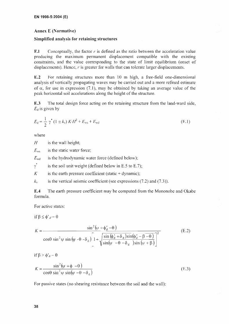


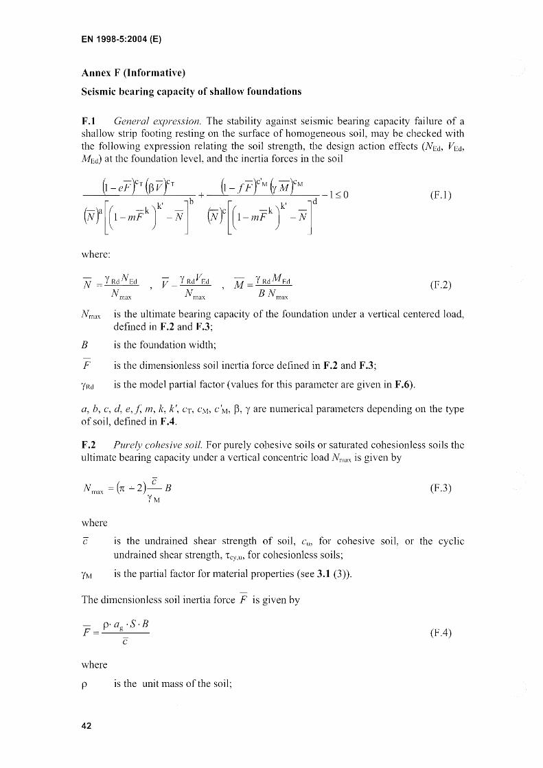


![EN 1993-3-1: Eurocode 3: Design of steel structures - Part ... 3... · EN 1990 Eurocode 0: EN 1991 Ellrocode 1: EN ]992 Eurocode 2: ... EN 1993-3-1 :2006 (E) EN 1998 Eurocode 8: Design](https://static.documents.pub/doc/80x56/5a7fd56a7f8b9aa24f8bfb62/en-1993-3-1-eurocode-3-design-of-steel-structures-part-3en-1990-eurocode.jpg)


