EN 206 1/30 Prof. Doolla EN 206 - Power Electronics and Machines Synchronous Machine Suryanarayana Doolla Department of Energy Science and Engineering Indian Institute of Technology, Bombay [email protected]
Transcript
EN 2061/30
Prof. Doolla
EN 206 - Power Electronics and MachinesSynchronous Machine
Suryanarayana DoollaDepartment of Energy Science and Engineering
Field is rotating (large size machines)Armature is stationary
Rotor
Salient pole (Low Speed- Hydro turbine)Non-Salient pole (High Speed Steam turbine)
Field is excited by ’dc’ supply
DC generatorPower Electronic converterBrush less excitation
AC voltage is available across armature/stationaryconductors
Concentrated windingDistributed winding
EN 2064/30
Prof. Doolla
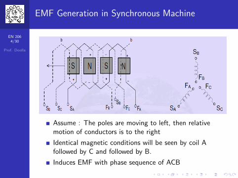
EMF Generation in Synchronous Machine
Assume : The poles are moving to left, then relativemotion of conductors is to the right
Identical magnetic conditions will be seen by coil Afollowed by C and followed by B.
Induces EMF with phase sequence of ACB
EN 2065/30
Prof. Doolla
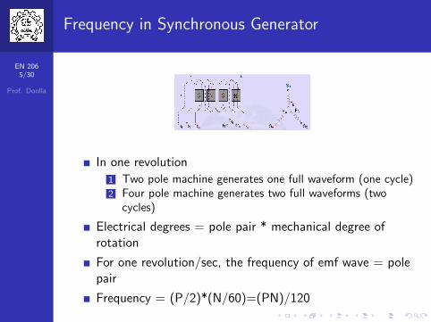
Frequency in Synchronous Generator
In one revolution
1 Two pole machine generates one full waveform (one cycle)2 Four pole machine generates two full waveforms (two
cycles)
Electrical degrees = pole pair * mechanical degree ofrotation
For one revolution/sec, the frequency of emf wave = polepair
Frequency = (P/2)*(N/60)=(PN)/120
EN 2066/30
Prof. Doolla
Construction - Generator
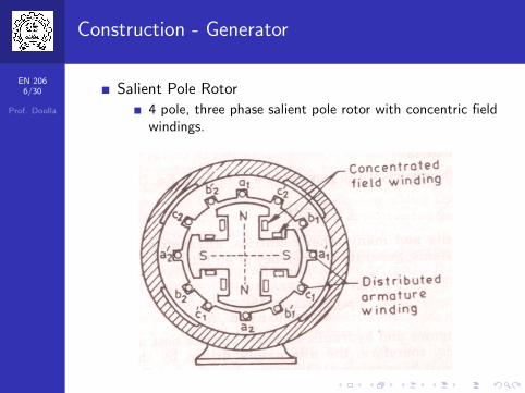
Salient Pole Rotor
4 pole, three phase salient pole rotor with concentric fieldwindings.
EN 2067/30
Prof. Doolla
Connections - Generator
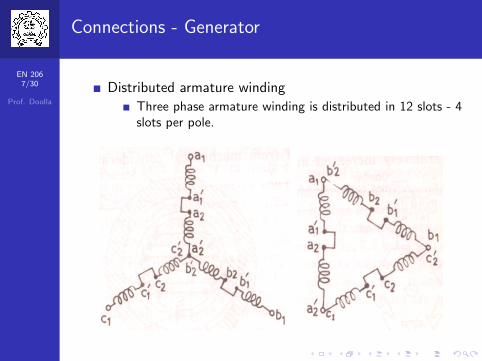
Distributed armature winding
Three phase armature winding is distributed in 12 slots - 4slots per pole.
EN 2068/30
Prof. Doolla
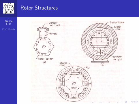
Rotor Structures
EN 2069/30
Prof. Doolla
Rotor MMF
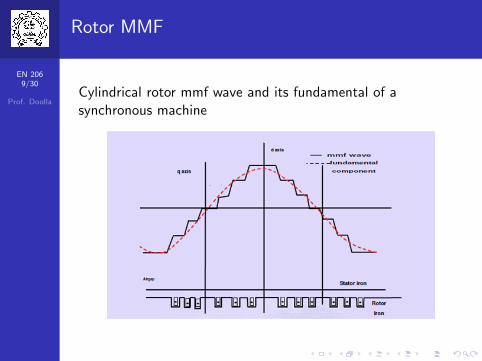
Cylindrical rotor mmf wave and its fundamental of asynchronous machine
EN 20610/30
Prof. Doolla
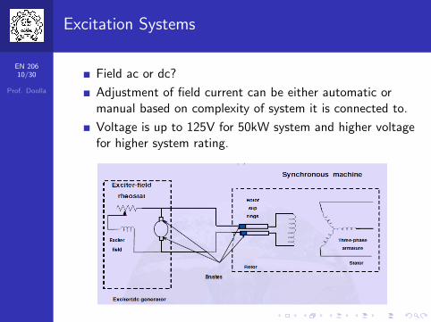
Excitation Systems
Field ac or dc?
Adjustment of field current can be either automatic ormanual based on complexity of system it is connected to.
Voltage is up to 125V for 50kW system and higher voltagefor higher system rating.
EN 20611/30
Prof. Doolla
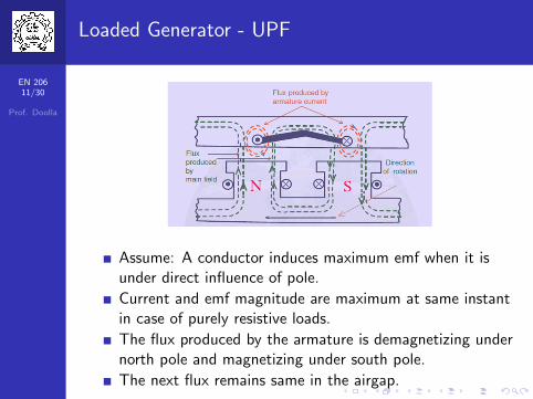
Loaded Generator - UPF
Assume: A conductor induces maximum emf when it isunder direct influence of pole.
Current and emf magnitude are maximum at same instantin case of purely resistive loads.
The flux produced by the armature is demagnetizing undernorth pole and magnetizing under south pole.
The next flux remains same in the airgap.
EN 20612/30
Prof. Doolla
Loaded Generator - ZPF (lagging)
Assume: A conductor induces maximum emf when it isunder direct influence of pole.
Current is maximum when voltage is minimum.
The flux produced by the armature is demagnetizing underboth north pole and south pole.
The next flux in the airgap reduces.
EN 20613/30
Prof. Doolla
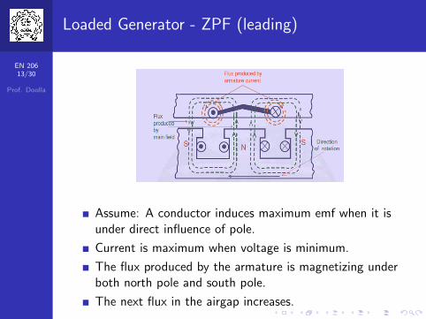
Loaded Generator - ZPF (leading)
Assume: A conductor induces maximum emf when it isunder direct influence of pole.
Current is maximum when voltage is minimum.
The flux produced by the armature is magnetizing underboth north pole and south pole.
The next flux in the airgap increases.
EN 20614/30
Prof. Doolla
Armature and Field mmf
If Ia lags emf by 900 (zero power factor) then it can beproven the Fa is entirely demagnetizing Ff .
If Ia leads emf by 900 (zero power factor) then it can beproven the Fa is entirely magnetizing Ff .
For motoring operation the same analysis is applicable bysubstituting Ia in place of IaIf armature current lags emf by 900, the nature ofarmature mmf is
demagnetizing in an alternatormagnetizing in a synchronous motor
If armature current leads emf by 900, the nature ofarmature mmf is
magnetizing in an alternatordemagnetizing in a synchronous motor
EN 20615/30
Prof. Doolla
Phasor Diagram-Resistive and inductive load
EN 20616/30
Prof. Doolla
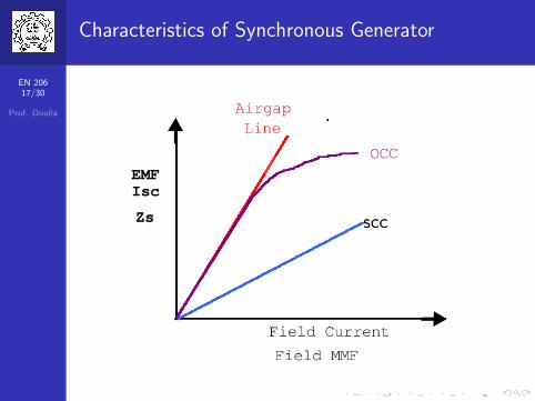
Characteristics of Synchronous Generator
Open circuit and short circuit characteristics are useful todetermine the parameters of a synchronous machine
OCC: The alternator is driven at rated speed and opencircuit voltage reading is noted as the field current isincreased. The final value of Ef should be 125% of therated voltage
OCC is also called as no-load, saturation or magnetizationcharacteristic and is not straight line because of saturationin the iron part of magnetic circuit.
SCC: The machine is driven at rated synchronous speedand the armature terminals are short-circuited through anammeter. The field current is varied till the armaturecurrent reading is 125 to 150% of rated value.
SCC is a straight line through origin. Saturation does notoccur as Fa is demagnetizing in nature
EN 20617/30
Prof. Doolla
Characteristics of Synchronous Generator
EN 20618/30
Prof. Doolla
Voltage Regulation of Synchronous Generator
It is defined as change in terminal voltage expressed as apercentage of the rated voltage, when the load at a givenpower factor is removed.
In case of small machines, this test can be directlyperformed
In case of large machines, it is not economical ortechnically feasible to perform voltage regulation test atlaboratory
Voltage regulation helps in
determining the voltage levels - insulation levelAutomatic voltage regulator equipment designSteady state short-circuit condition and stability areeffected by the voltage regulationParallel operation of one alternator with other alternator,is effected considerable by voltage regulation
EN 20619/30
Prof. Doolla
Methods - Determine Voltage Regulation
EMF method or synchronous impedance method(Pessimistic approach)
Applicable for cylindrical rotor machinesThe lowest values of Zs obtained from largest value of SCCis used in computationSCC: The effect of armature flux is demagnetizing andhence the flux density is much less than the flux density inactual condition - an unsaturated value of Zs is obtained.
Mmf method (Optimistic Approach)
ZPF method (Potier traingle)
New ASA method
Saturated synchronous reactance method
EN 20620/30
Prof. Doolla
EMF Method - Cylindrical rotor
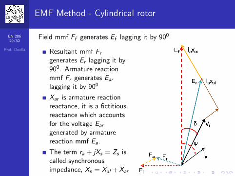
Field mmf Ff generates Ef lagging it by 900
Resultant mmf Frgenerates Er lagging it by900. Armature reactionmmf Fr generates Ear
lagging it by 900
Xar is armature reactionreactance, it is a fictitiousreactance which accountsfor the voltage Ear
generated by armaturereaction mmf Ea.
The term ra + jXs = Zs iscalled synchronousimpedance, Xs = Xal +Xar
EN 20621/30
Prof. Doolla
Synchronous Motor - Phasor Diagram
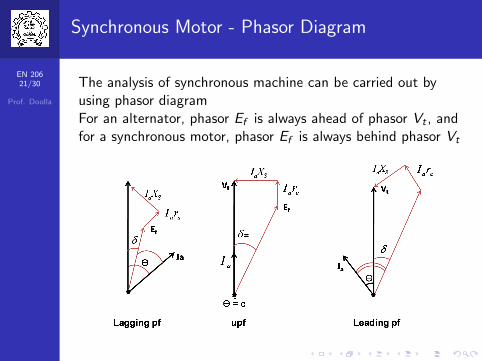
The analysis of synchronous machine can be carried out byusing phasor diagramFor an alternator, phasor Ef is always ahead of phasor Vt , andfor a synchronous motor, phasor Ef is always behind phasor Vt
EN 20622/30
Prof. Doolla
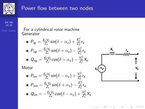
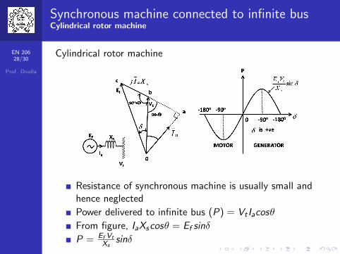
Power flow between two nodes
For a cylindrical rotor machineGenerator
Pig = Ef VtZs
sin(δ − αz) +E2f
Z2sra
Pog = Ef VtZs
sin(δ + αz)− V 2t
Z2sra
Qog = Ef VtZs
cos(δ + αz)− V 2t
Z2sXs
Motor
Pim = Ef VtZs
sin(δ − αz) + V 2t
Z2sra
Pom = Ef VtZs
sin(δ + αz)− E2f
Z2sra
Qim = −Ef VtZs
cos(δ − αz) + V 2t
Z2sXs
EN 20623/30
Prof. Doolla
Problem
A synchronous machine has been synchronized with an infinitebus. Now, without changing the field current, the machine ismade to deliver real power to the bus. Will it, at the sametime, generate or consume reactive power?
For proper synchronization, Vt = Ef , therefore, reactive
power Q = V 2t
Xs(cosδ − 1).
As the motor is supplying active power δ 6= 0 and alsocosδ < 1, therefore Q is negative.
Q is negative, indicates that the generator is absorbingreactive power.
EN 20624/30
Prof. Doolla
Problem
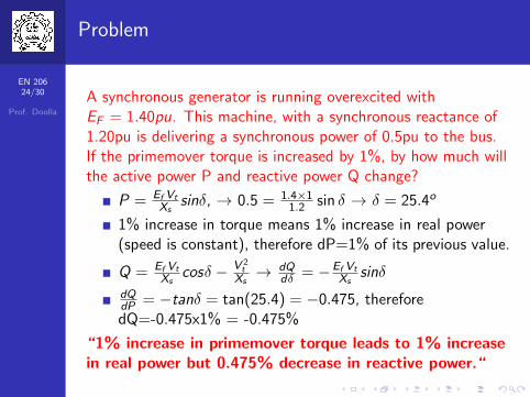
A synchronous generator is running overexcited withEF = 1.40pu. This machine, with a synchronous reactance of1.20pu is delivering a synchronous power of 0.5pu to the bus.If the primemover torque is increased by 1%, by how much willthe active power P and reactive power Q change?
P = Ef VtXs
sinδ, → 0.5 = 1.4×11.2 sin δ → δ = 25.4o
1% increase in torque means 1% increase in real power(speed is constant), therefore dP=1% of its previous value.
“1% increase in primemover torque leads to 1% increasein real power but 0.475% decrease in reactive power.“
EN 20624/30
Prof. Doolla
Problem
A synchronous generator is running overexcited withEF = 1.40pu. This machine, with a synchronous reactance of1.20pu is delivering a synchronous power of 0.5pu to the bus.If the primemover torque is increased by 1%, by how much willthe active power P and reactive power Q change?
P = Ef VtXs
sinδ, → 0.5 = 1.4×11.2 sin δ → δ = 25.4o
1% increase in torque means 1% increase in real power(speed is constant), therefore dP=1% of its previous value.
“1% increase in primemover torque leads to 1% increasein real power but 0.475% decrease in reactive power.“
EN 20625/30
Prof. Doolla
Reactive Power Flow
Generator
When Ef cosδ > Vt (over excited), Qog is positive anddelivers reactive power, alternator operates at lagging pf
When Ef cosδ = Vt (normal excited), Qog is zero andalternator operates at unity pf
When Ef cosδ < Vt (under excited), Qog is negative andabsorbs reactive power, alternator operates at leading pf
Motor
When Ef cosδ > Vt (over excited), Qim is negative anddelivers reactive power, motor operates at leading pf
When Ef cosδ = Vt (normal excited), Qim is zero andalternator operates at unity pf
When Ef cosδ < Vt (under excited), Qim is positive andabsorbs reactive power, motor operates at lagging pf
EN 20626/30
Prof. Doolla
Problem
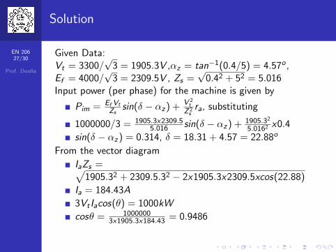
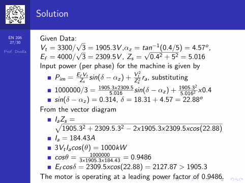
A 3300V, star connected synchronous motor hassynchronous impedance of 0.4+j0.5 ohm/phase. For anexcitation emf of 4000V and motor input power of1000kW at rated voltage, compute the line current andpower factor.
EN 20627/30
Prof. Doolla
Solution
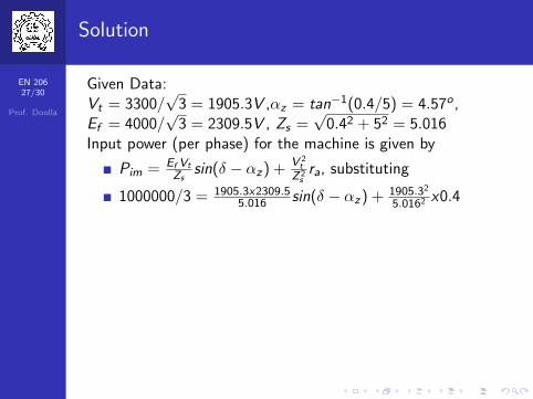
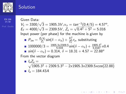
Given Data:Vt = 3300/
√3 = 1905.3V ,αz = tan−1(0.4/5) = 4.57o ,
Ef = 4000/√
3 = 2309.5V , Zs =√
0.42 + 52 = 5.016Input power (per phase) for the machine is given by