66
ETSI EN 300 175-2 V2.4.1 (2012-04) Digital Enhanced Cordless Telecommunications (DECT); Common Interface (CI); Part 2: Physical Layer (PHL) European Standard

ETSI EN 300 175-2 V2.4.1 (2012-04)
Digital Enhanced Cordless Telecommunications (DECT); Common Interface (CI);
Part 2: Physical Layer (PHL)
European Standard
ETSI
ETSI EN 300 175-2 V2.4.1 (2012-04) 2
Reference REN/DECT-000258
Keywords DECT, IMT-2000, mobility, radio, TDD, TDMA
ETSI
650 Route des Lucioles F-06921 Sophia Antipolis Cedex - FRANCE
Tel.: +33 4 92 94 42 00 Fax: +33 4 93 65 47 16
Siret N° 348 623 562 00017 - NAF 742 C
Association à but non lucratif enregistrée à la Sous-Préfecture de Grasse (06) N° 7803/88
Important notice
Individual copies of the present document can be downloaded from: http://www.etsi.org
The present document may be made available in more than one electronic version or in print. In any case of existing or perceived difference in contents between such versions, the reference version is the Portable Document Format (PDF).
In case of dispute, the reference shall be the printing on ETSI printers of the PDF version kept on a specific network drive within ETSI Secretariat.
Users of the present document should be aware that the document may be subject to revision or change of status. Information on the current status of this and other ETSI documents is available at
http://portal.etsi.org/tb/status/status.asp
If you find errors in the present document, please send your comment to one of the following services: http://portal.etsi.org/chaircor/ETSI_support.asp
Copyright Notification
No part may be reproduced except as authorized by written permission. The copyright and the foregoing restriction extend to reproduction in all media.
© European Telecommunications Standards Institute 2012.
All rights reserved.
DECTTM, PLUGTESTSTM, UMTSTM and the ETSI logo are Trade Marks of ETSI registered for the benefit of its Members. 3GPPTM and LTE™ are Trade Marks of ETSI registered for the benefit of its Members and
of the 3GPP Organizational Partners. GSM® and the GSM logo are Trade Marks registered and owned by the GSM Association.
ETSI
ETSI EN 300 175-2 V2.4.1 (2012-04) 3
Contents
Intellectual Property Rights ................................................................................................................................ 7
Foreword ............................................................................................................................................................. 7
1 Scope ........................................................................................................................................................ 8
2 References ................................................................................................................................................ 8
2.1 Normative references ......................................................................................................................................... 8
2.2 Informative references ........................................................................................................................................ 9
3 Definitions and abbreviations ................................................................................................................. 10
3.1 Definitions ........................................................................................................................................................ 10
3.2 Abbreviations ................................................................................................................................................... 11
4 PHL services .......................................................................................................................................... 12
4.1 RF channels (access in frequency) ................................................................................................................... 13
4.1.1 Nominal position of RF carriers ................................................................................................................. 13
4.1.2 Accuracy and stability of RF carriers ......................................................................................................... 13
4.2 Time Division Multiple Access (TDMA) structure (access in time) ................................................................ 14
4.2.1 Frame, full-slot, double-slot, half-slot and variable capacity slot structure (including long slot) ............... 14
4.2.2 Reference timer accuracy and stability ....................................................................................................... 15
4.2.3 RFP transmission jitter................................................................................................................................ 16
4.2.4 PP reference timer synchronization ............................................................................................................ 16
4.2.5 System synchronization .............................................................................................................................. 16
4.2.6 Inter-system synchronization ...................................................................................................................... 16
4.2.7 Reference timer adjustment for synchronization ........................................................................................ 17
4.3 Cells (access in space) ...................................................................................................................................... 17
4.4 Physical packets ............................................................................................................................................... 17
4.4.1 The short physical packet P00 .................................................................................................................... 17
4.4.2 The basic physical packet P32 .................................................................................................................... 18
4.4.3 The variable capacity physical packet P00j ................................................................................................ 18
4.4.4 The high capacity physical packet P80 ....................................................................................................... 19
4.5 Physical channels ............................................................................................................................................. 19
4.5.1 Ra (K, L, M, N) notation ............................................................................................................................ 19
4.5.2 The short physical channel R00 (K, L, M, N) ............................................................................................. 20
4.5.3 The basic physical channel R32 (K, L, M, N) ............................................................................................ 20
4.5.4 The variable-rate physical channel R00j (K, L, M, N) ............................................................................... 21
4.5.5 The high capacity physical channel R80 (K, L, M, N) ............................................................................... 22
4.6 Synchronization field S .................................................................................................................................... 22
4.7 D-field .............................................................................................................................................................. 23
4.7.1 Physical packet P00 .................................................................................................................................... 23
4.7.2 Physical packet P32 .................................................................................................................................... 23
4.7.3 Physical packet P00j ................................................................................................................................... 23
4.7.4 Physical packet P80 .................................................................................................................................... 23
4.8 Z-field ............................................................................................................................................................... 24
4.9 Bit pattern during ramping ............................................................................................................................... 24
5 Transmission of physical packets ........................................................................................................... 24
5.1 Definitions ........................................................................................................................................................ 24
5.1.1 End of the physical packet .......................................................................................................................... 24
5.1.2 Transmitted power ...................................................................................................................................... 24
5.1.3 Normal Transmitted Power (NTP) .............................................................................................................. 25
5.2 Transmission burst ........................................................................................................................................... 25
5.2.1 Transmitter attack time ............................................................................................................................... 25
5.2.2 Transmitter release time .............................................................................................................................. 25
5.2.3 Minimum power ......................................................................................................................................... 25
5.2.4 Maximum power ......................................................................................................................................... 25
5.2.5 Maintenance of transmission after packet end ............................................................................................ 25
5.2.6 Transmitter idle power output ..................................................................................................................... 25
ETSI
ETSI EN 300 175-2 V2.4.1 (2012-04) 4
5.3 Transmitted power ............................................................................................................................................ 26
5.3.1 Peak power per transceiver ......................................................................................................................... 26
5.3.1.1 PP and RFP with an integral antenna .................................................................................................... 26
5.3.1.2 PP and RFP with external connections for all antennas ........................................................................ 26
5.3.2 Maximum EIRP and number of transceivers .............................................................................................. 26
5.4 RF carrier modulation ...................................................................................................................................... 26
5.4.1 Modulation method ..................................................................................................................................... 26
5.4.2 Definition of "1" and "0" ............................................................................................................................ 27
5.4.3 Deviation limits .......................................................................................................................................... 27
5.5 Unwanted RF power radiation .......................................................................................................................... 27
5.5.1 Emissions due to modulation ...................................................................................................................... 27
5.5.2 Emissions due to transmitter transients ....................................................................................................... 28
5.5.3 Emissions due to intermodulation ............................................................................................................... 28
5.5.4 Spurious emissions when allocated a transmit channel .............................................................................. 28
6 Reception of physical packets ................................................................................................................ 29
6.1 Definitions and conditions for clause 6 ............................................................................................................ 29
6.1.1 Power levels and field strength ................................................................................................................... 29
6.1.2 Test conditions ............................................................................................................................................ 29
6.1.3 Reference DECT radio end point ................................................................................................................ 29
6.2 Radio receiver sensitivity ................................................................................................................................. 29
6.3 Radio receiver reference bit error rate and frame error ratio ............................................................................ 30
6.4 Radio receiver interference performance.......................................................................................................... 30
6.5 Radio receiver blocking .................................................................................................................................... 30
6.5.1 Owing to signals occurring at the same time but on other frequencies ....................................................... 30
6.5.2 Owing to signals occurring at a different time ............................................................................................ 31
6.6 Receiver intermodulation performance ............................................................................................................ 31
6.7 Spurious emissions when not allocated a transmit channel .............................................................................. 31
6.7.1 Out of band ................................................................................................................................................. 31
6.7.2 In the DECT band ....................................................................................................................................... 31
7 Primitives between physical layer and other entities ............................................................................. 31
7.1 Medium access control layer (D-SAP) ............................................................................................................. 32
7.1.1 PL_TX {req} .............................................................................................................................................. 32
7.1.2 PL_RX {req, cfm} ...................................................................................................................................... 32
7.1.3 PL_FREQ_ADJ {req} ................................................................................................................................ 33
7.2 Management entity (PM-SAP) ......................................................................................................................... 33
7.2.1 PL_ME_SYNC {req, cfm} ......................................................................................................................... 33
7.2.2 PL_ME_SIG_STR {req, cfm} .................................................................................................................... 33
7.2.3 PL_ME_TIME_ADJ {req, cfm} ................................................................................................................. 33
8 PHL procedures ...................................................................................................................................... 33
8.1 Addition of synchronization field and transmission ......................................................................................... 33
8.2 Packet reception and removal of synchronization field .................................................................................... 34
8.3 Measurement of signal strength ........................................................................................................................ 34
8.4 Synchronization pulse detection ....................................................................................................................... 34
8.5 Timing adjustment ............................................................................................................................................ 35
8.6 Frequency adjustment ....................................................................................................................................... 35
9 Management entity procedures related to PHL ...................................................................................... 35
9.1 List of quietest physical channels ..................................................................................................................... 35
9.2 Physical channels with greatest field strength (PP only) .................................................................................. 35
9.3 Extract timing ................................................................................................................................................... 35
Annex A (informative): RF exposure requirements ............................................................................ 36
A.1 Recommendation .................................................................................................................................... 36
A.2 Compliance distances ............................................................................................................................. 36
Annex B (normative): Synchronization port ..................................................................................... 38
B.1 General requirements ............................................................................................................................. 38
B.2 Wired synchronization ports .................................................................................................................. 38
ETSI
ETSI EN 300 175-2 V2.4.1 (2012-04) 5
B.2.1 Synchronization signal ..................................................................................................................................... 39
B.3 GPS synchronization .............................................................................................................................. 40
B.3.1 Synchronization signal ..................................................................................................................................... 41
B.3.2 DECT timings derivation from the GPS time................................................................................................... 41
B.3.2.1 DECT multiframe number synchronization using GPS .............................................................................. 42
B.3.2.2 DECT PSCN synchronization using GPS ................................................................................................... 42
B.4 Guidance for installation ........................................................................................................................ 43
B.4.1 Interconnection cable ....................................................................................................................................... 43
B.4.2 Propagation delay of synchronization signals .................................................................................................. 43
B.4.2.1 Calculation of Propagation delay (informative) .......................................................................................... 43
B.4.2.2 Delay compensation .................................................................................................................................... 44
B.4.3 GPS receiver stability ....................................................................................................................................... 44
Annex C (informative): Prolonged preamble ....................................................................................... 45
C.1 Bit pattern ............................................................................................................................................... 45
C.2 The power-time template........................................................................................................................ 45
Annex D (normative): 4-level/8-level/16-level/64-level modulation option ..................................... 46
D.1 The π/2-DBPSK modulation scheme ..................................................................................................... 47
D.1.1 RF carrier modulation ...................................................................................................................................... 47
D.1.1.1 Modulation accuracy................................................................................................................................... 47
D.1.2 Transmission of physical packets ..................................................................................................................... 47
D.2 The π/4-DQPSK modulation scheme ..................................................................................................... 48
D.2.1 RF carrier modulation ...................................................................................................................................... 48
D.2.1.1 Modulation accuracy................................................................................................................................... 48
D.2.2 Transmission of physical packets ..................................................................................................................... 48
D.3 The π/8-D8PSK modulation scheme ...................................................................................................... 48
D.3.1 RF carrier modulation ...................................................................................................................................... 48
D.3.1.1 Modulation accuracy................................................................................................................................... 49
D.3.2 Transmission of physical packets ..................................................................................................................... 49
D.4 The 16 QAM modulation scheme .......................................................................................................... 49
D.4.1 RF carrier modulation ...................................................................................................................................... 49
D.4.1.1 Modulation accuracy................................................................................................................................... 50
D.4.2 Transmission of physical packets ..................................................................................................................... 50
D.5 The 64 QAM modulation scheme .......................................................................................................... 50
D.5.1 RF carrier modulation ...................................................................................................................................... 50
D.5.1.1 Modulation accuracy................................................................................................................................... 51
D.5.2 Transmission of physical packets ..................................................................................................................... 52
D.6 Transmission of physical packets ........................................................................................................... 52
D.6.1 Error vector magnitude definition .................................................................................................................... 52
D.6.2 EVM requirement ............................................................................................................................................. 52
Annex E (normative): Power control procedures ............................................................................. 53
E.1 Definitions of parameters and relations between parameters ................................................................. 54
E.2 Procedure for PP power adjustment due to movement .......................................................................... 55
E.3 Setting the power control threshold, RSSpT .......................................................................................... 55
Annex F (normative): DECT carrier numbers and carrier positions in the range 1 880 MHz to 2 025 MHz and for the US market 902 MHz to 928 MHz and 2 400 MHz to 2 483,5 MHz ............................................................................ 57
F.1 Introduction ............................................................................................................................................ 57
F.2 1 880 MHz to 1 978 MHz and 2 010 MHz to 2 025 MHz RF band 00001 ............................................ 58
ETSI
ETSI EN 300 175-2 V2.4.1 (2012-04) 6
F.3 1 880 MHz to 1 925 MHz and 2 010 MHz to 2 025 MHz RF band 00010 ............................................ 59
F.4 1 880 MHz to 1 900 MHz, 1 915 MHz to 1 940 MHz and 2 010 MHz to 2 025 MHz RF band 00011 ...................................................................................................................................................... 60
F.5 1 880 MHz to 1 900 MHz, 1 935 MHz to 1 960 MHz and 2 010 MHz to 2 025 MHz RF band 00100 ...................................................................................................................................................... 61
F.6 1 880 MHz to 1 900 MHZ, 1 955 MHz to 1 980 MHz and 2 010 MHz to 2 025 MHz RF band 00101 ...................................................................................................................................................... 62
F.7 US ISM band carriers ............................................................................................................................. 63
F.7.1 902 MHz to 928 MHz RF band 01000 ............................................................................................................. 63
F.7.2 2 400 MHz to 2 483,5 MHz RF band 01001 .................................................................................................... 63
Annex G (informative): Bibliography ................................................................................................... 64
Annex H (informative): Change history ............................................................................................... 65
History .............................................................................................................................................................. 66
ETSI
ETSI EN 300 175-2 V2.4.1 (2012-04) 7
Intellectual Property Rights IPRs essential or potentially essential to the present document may have been declared to ETSI. The information pertaining to these essential IPRs, if any, is publicly available for ETSI members and non-members, and can be found in ETSI SR 000 314: "Intellectual Property Rights (IPRs); Essential, or potentially Essential, IPRs notified to ETSI in respect of ETSI standards", which is available from the ETSI Secretariat. Latest updates are available on the ETSI Web server (http://ipr.etsi.org).
Pursuant to the ETSI IPR Policy, no investigation, including IPR searches, has been carried out by ETSI. No guarantee can be given as to the existence of other IPRs not referenced in ETSI SR 000 314 (or the updates on the ETSI Web server) which are, or may be, or may become, essential to the present document.
Foreword This European Standard (EN) has been produced by ETSI Technical Committee Digital Enhanced Cordless Telecommunications (DECT).
The present document is part 2 of a multi-part deliverable. Full details of the entire series can be found in part 1 [1].
Further details of the DECT system may be found in TR 101 178 [i.1] and ETR 043 [i.2].
National transposition dates
Date of adoption of this EN: 17 April 2012
Date of latest announcement of this EN (doa): 31 July 2012
Date of latest publication of new National Standard or endorsement of this EN (dop/e):
31 January 2013
Date of withdrawal of any conflicting National Standard (dow): 31 January 2013
ETSI
ETSI EN 300 175-2 V2.4.1 (2012-04) 8
1 Scope The present document is one of the parts of the specification of the Digital Enhanced Cordless Telecommunications (DECT) Common Interface (CI).
The present document specifies the physical channel arrangements. DECT physical channels are radio communication paths between two radio end points. A radio end point is either part of the fixed infrastructure, a privately owned Fixed Part (FP), typically a base station, or a Portable Part (PP), typically a handset. The assignment of one or more particular physical channels to a call is the task of higher layers.
The Physical Layer (PHL) interfaces with the Medium Access Control (MAC) layer, and with the Lower Layer Management Entity (LLME). On the other side of the PHL is the radio transmission medium which has to be shared extensively with other DECT users and a wide variety of other radio services. The tasks of the PHL can be grouped into five categories:
a) to modulate and demodulate radio carriers with a bit stream of a defined rate to create a radio frequency channel;
b) to acquire and maintain bit and slot synchronization between transmitters and receivers;
c) to transmit or receive a defined number of bits at a requested time and on a particular frequency;
d) to add and remove the synchronization field and the Z-field used for rear end collision detection;
e) to observe the radio environment to report signal strengths.
The present document includes New Generation DECT, a further development of the DECT standard introducing wideband speech, improved data services, new slot types and other technical enhancements.
2 References References are either specific (identified by date of publication and/or edition number or version number) or non-specific. For specific references, only the cited version applies. For non-specific references, the latest version of the reference document (including any amendments) applies.
Referenced documents which are not found to be publicly available in the expected location might be found at http://docbox.etsi.org/Reference.
NOTE: While any hyperlinks included in this clause were valid at the time of publication ETSI cannot guarantee their long term validity.
2.1 Normative references The following referenced documents are necessary for the application of the present document.
[1] ETSI EN 300 175-1: "Digital Enhanced Cordless Telecommunications (DECT); Common Interface (CI); Part 1: Overview".
[2] Void.
[3] ETSI EN 300 175-3: "Digital Enhanced Cordless Telecommunications (DECT); Common Interface (CI); Part 3: Medium Access Control (MAC) layer".
[4] ETSI EN 300 175-4: "Digital Enhanced Cordless Telecommunications (DECT); Common Interface (CI); Part 4: Data Link Control (DLC) layer".
[5] ETSI EN 300 175-5: "Digital Enhanced Cordless Telecommunications (DECT); Common Interface (CI); Part 5: Network (NWK) layer".
ETSI
ETSI EN 300 175-2 V2.4.1 (2012-04) 9
[6] ETSI EN 300 175-6: "Digital Enhanced Cordless Telecommunications (DECT); Common Interface (CI); Part 6: Identities and addressing".
[7] Void.
[8] Void.
[9] ETSI EN 300 176-1: "Digital Enhanced Cordless Telecommunications (DECT); Test specification; Part 1: Radio".
[10] ITU-R Recommendation M.1457-6: "Detailed specifications of the radio interfaces of International Mobile Telecommunications-2000 (IMT-2000)".
[11] ITU-T Recommendation V.11: "Electrical characteristics for balanced double-current interchange circuits operating at data signalling rates up to 10 Mbit/s".
[12] Federal Communications Commission FCC 02-151: "Second Report and Order, Amendment of Part 15 of the Commission's Rules Regarding Spread Spectrum Devices".
[13] CEPT/ECC/DEC/(06)01: "ECC Decision of 24 March 2006 on the harmonized utilization of spectrum for terrestrial IMT-2000/UMTS systems operating within the bands 1900 - 1980 MHz, 2010 - 2025 MHz and 2110 - 2170 MHz".
2.2 Informative references The following referenced documents are not necessary for the application of the present document but they assist the user with regard to a particular subject area.
[i.1] ETSI TR 101 178: "Digital Enhanced Cordless Telecommunications (DECT); A High Level Guide to the DECT Standardization".
[i.2] ETSI ETR 043: "Digital Enhanced Cordless Telecommunications (DECT); Common Interface (CI); Services and facilities requirements specification".
[i.3] International Commission on Non-Ionizing Radiation Protection (ICNIRP): "Guidelines for limiting exposure to time-varying electric, magnetic, and electromagnetic fields (up to 300 GHz), Health Physics", vol. 74, pp 494-522, April 1998.
[i.4] Council Recommendation 1999/519/EC of 12 July 1999 on the limitation of exposure of the general public to electromagnetic fields (0 Hz to 300 GHz) (Official Journal of the European Communities, July 1999).
[i.5] CENELEC EN 50360: "Product standard to demonstrate the compliance of mobile phones with the basic restrictions related to human exposure to electromagnetic fields (300 MHz - 3 GHz)", European Committee for Electrotechnical Standardization (CENELEC), July 2001. (Harmonized standard listed under the R&TTE directive).
[i.6] CENELEC EN 50385: "Product standard to demonstrate the compliance of radio base stations and fixed terminal stations for wireless telecommunication systems with the basic restrictions or the reference levels related to human exposure to radio frequency electromagnetic fields (110 MHz - 40 GHz) - General public", European Committee for Electrotechnical Standardization (CENELEC), November 2001 (draft).
[i.7] CENELEC EN 50383: "Basic standard for the calculation and measurement of electromagnetic field strength and SAR related to human exposure from radio base stations and fixed terminal stations for wireless telecommunication systems (110 MHz - 40 GHz)", European Committee for Electrotechnical Standardization (CENELEC), November 2001 (draft).
[i.8] IEEE 802.11b: "Standard for Information Technology - Telecommunications and Information Exchange Between Systems - Local and Metropolitan Area Networks - Specific Requirements - Part 11: Wireless LAN Medium Access Control (MAC) and Physical Layer (PHY) Specifications".
ETSI
ETSI EN 300 175-2 V2.4.1 (2012-04) 10
3 Definitions and abbreviations
3.1 Definitions For the purposes of the present document, the following terms and definitions apply:
antenna diversity: See EN 300 175-1 [1].
cell: See EN 300 175-1 [1].
Central Control Fixed Part (CCFP): See EN 300 175-1 [1].
channel: See EN 300 175-1 [1].
cluster: See EN 300 175-1 [1].
Connection Oriented mode (C/O): See EN 300 175-1 [1].
Cordless Radio Fixed Part (CRFP): See EN 300 175-1 [1].
coverage area: See EN 300 175-1 [1].
DECT Network (DNW): See EN 300 175-1 [1].
double duplex bearer: See EN 300 175-1 [1].
double simplex bearer: See EN 300 175-1 [1].
double slot: See EN 300 175-1 [1].
down-link: See EN 300 175-1 [1].
duplex bearer: See EN 300 175-1 [1].
Fixed Part (DECT Fixed Part) (FP): See EN 300 175-1 [1].
Fixed radio Termination (FT): See EN 300 175-1 [1].
frame: See EN 300 175-1 [1].
full slot (slot): See EN 300 175-1 [1].
guard space: See EN 300 175-1 [1].
half slot: See EN 300 175-1 [1].
handover: See EN 300 175-1 [1].
IMT-2000: International Mobile Telecommunications, Third Generation Mobile Systems
IMT-FT: International Mobile Telecommunications, FDMA/TDMA
NOTE: This is the DECT family member of IMT-2000.
intercell handover: See EN 300 175-1 [1].
intracell handover: See EN 300 175-1 [1].
Lower Layer Management Entity (LLME): See EN 300 175-1 [1].
multiframe: See EN 300 175-1 [1].
New Generation DECT: See EN 300 175-1 [1].
physical channel (channel): See EN 300 175-1 [1].
ETSI
ETSI EN 300 175-2 V2.4.1 (2012-04) 11
Portable Part (DECT Portable Part) (PP): See EN 300 175-1 [1].
Portable radio Termination (PT): See EN 300 175-1 [1].
public access service: See EN 300 175-1 [1].
radio channel: See EN 300 175-1 [1].
radio end point: See EN 300 175-1 [1].
Radio Fixed Part (RFP): See EN 300 175-1 [1].
Repeater Part (REP): See EN 300 175-1 [1].
RF carrier (carrier): See EN 300 175-1 [1].
RF channel: See EN 300 175-1 [1].
simplex bearer: See EN 300 175-1 [1].
Single Radio Fixed Part (SRFP): See EN 300 175-1 [1].
TDMA frame: See EN 300 175-1 [1].
Wireless Relay Station (WRS): See EN 300 175-1 [1].
3.2 Abbreviations For the purposes of the present document, the following abbreviations apply:
AC ACcuracy AM Amplitude Modulation BER Bit Error Rate CCFP Central Control Fixed Part CI Common Interface (standard) CRFP Cordless Radio Fixed Part CTA Cordless Terminal Adapter dBm dB relative to 1 milliwatt DBPSK Differential Binary Phase Shift Keying DC Direct Current DLC Data Link Control layer DNW DECT Network DQPSK Differential Quaternary Phase Shift Keying D-SAP Data field-Service Access Point DSV Digital Sum Variation EIRP Equivalent Isotropically Radiated Power ERP Effective Radiated Power EVM Error-Vector Magnitude FMID Fixed part MAC IDentity FP Fixed Part FT Fixed radio Termination Fy Frequency GFSK Gaussian Frequency Shift Keying GMSK Gaussian Minimum Shift Keying GPS Global Positioning System HLM High Level Modulation ICNIRP International Commission on Non-Ionizing Radiation Protection iDCS instant Dynamic Channel Selection IMT-FT International Mobile Telecommunications - Frequency Time ISM Industrial, Scientific and Medical LCD Largest Common Denominator LLME Lower Layer Management Entity MAC Medium Access Control layer MCM Minimum Common Multiple
ETSI
ETSI EN 300 175-2 V2.4.1 (2012-04) 12
MF Fading Margin MFN MultiFrame Number NTP Normal Transmitted Power NWK NetWorK PCMCIA Personal Computer Memory Card International Association PHL PHysical Layer PM-SAP Physical layer Management entity - Service Access Point PP Portable Part ppm parts per million PSCN Primary receiver Scan Carrier Number PT Portable radio Termination REP REpeater Part RF Radio Frequency RFP Radio Fixed Part RMS Root Mean Square RPN Radio fixed Part Number RSSp Radio Signal Strength PP SAP Service Access Point SAR Specific Absorption Rate SDU Service Data Unit SRFP Single Radio Fixed Part TDD Time Division Duplex TDMA Time Division Multiple Access UMTS Universal Mobile Telecommunication System UTC Universal Time Coordinated VF cable Velocity Factor WLAN Wireless Local Area Network WRS Wireless Relay Station
4 PHL services A physical channel provides a simplex bit-pipe between two radio end points. To establish, for example, a duplex telephone connection, two physical channels have to be established between the endpoints.
Radio spectrum is needed to create a physical channel. The radio spectrum space has three dimensions:
• geometric (geographic) space;
• frequency;
• time.
Spectrum is assigned to physical channels by sharing it in these three dimensions.
DECT provides a mechanism called "handover" to release a physical channel and to establish another one in any or all of the three dimensions without releasing the end-to-end connection.
The requirements of the present document should be read in conjunction with EN 300 176-1 [9].
The requirements specified apply for nominal conditions unless extreme conditions are stated. Tests at extreme conditions may include combinations of limit values of extreme temperature and of power supply variation, defined for each case in EN 300 176-1 [9].
Nominal and extreme temperature ranges are defined below:
Nominal temperature: PP, FP, RFP, CCFP +15 °C to +35 °C;
Extreme temperature: PP 0 °C to +40 °C;
FP, RFP, CCFP, class E1 +10 °C to +40 °C;
FP, RFP, CCFP, class E2 -10 °C to +55 °C.
ETSI
ETSI EN 300 175-2 V2.4.1 (2012-04) 13
The environmental class E1 refers to installation in indoor heated and/or cooled areas allowing for personal comfort, e.g. homes, offices, laboratories or workshops. The environmental class E2 refers to all other installations.
For nominal temperature, each measurement is made at the temperature of the test site, which shall be within +15 °C to +35 °C. For extreme temperatures, additional measurements are made, at each limit value of the extreme temperature.
4.1 RF channels (access in frequency)
4.1.1 Nominal position of RF carriers
DECT carriers are specified for the whole frequency range 1 880 MHz to 1 980 MHz and 2 010 MHz to 2 025 MHz. Carrier positions in the 902 MHz to 928 MHz ISM band and the 2 400 MHz to 2 483,5 MHz ISM band have been defined for the US market [12].
DECT is also an IMT-2000 [10] family member, called IMT-FT, the only member that provides for uncoordinated installations on an unlicensed spectrum. RF carriers for IMT-FT applications of DECT are placed within the parts of the European UMTS spectrum applicable for TDD operation. (See ECC/DEC/(06)01 [13].) E.g. within 1 900 MHz to 1 920 MHz, 1 920 MHz to 1 980 MHz and/or 2 010 MHz to 2 025 MHz.
The most common spectrum allocation is 1 880 MHz to 1 900 MHz, but outside Europe spectrum is also available in 1 900 MHz to 1 920 MHz and in 1 910 MHz to 1 930 MHz (several countries).
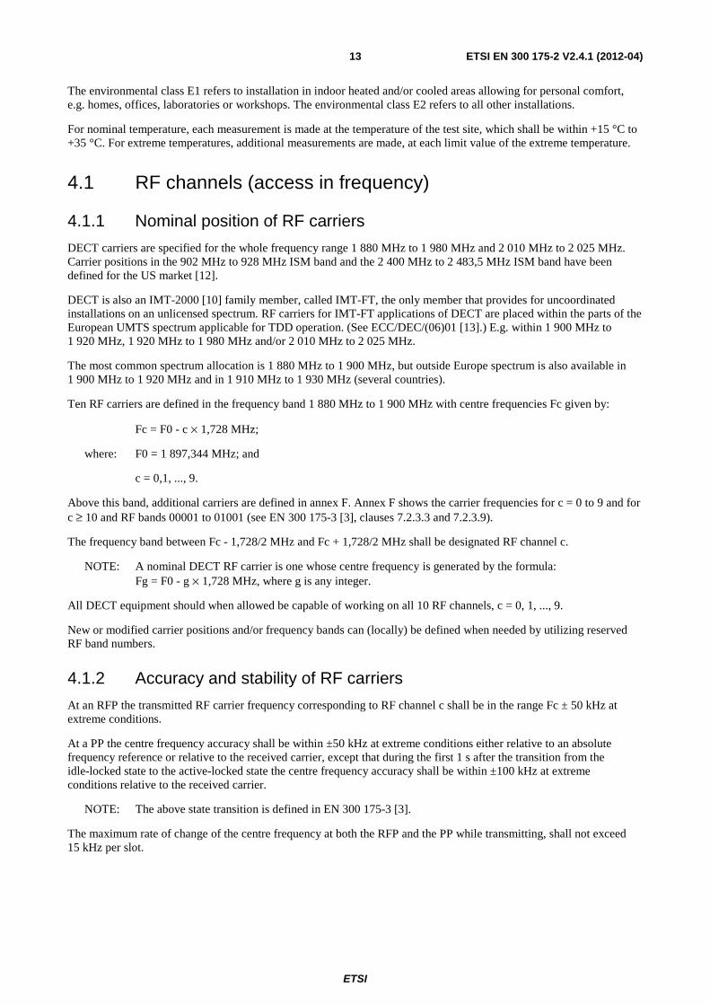
Ten RF carriers are defined in the frequency band 1 880 MHz to 1 900 MHz with centre frequencies Fc given by:
Fc = F0 - c × 1,728 MHz;
where: F0 = 1 897,344 MHz; and
c = 0,1, ..., 9.
Above this band, additional carriers are defined in annex F. Annex F shows the carrier frequencies for c = 0 to 9 and for c ≥ 10 and RF bands 00001 to 01001 (see EN 300 175-3 [3], clauses 7.2.3.3 and 7.2.3.9).
The frequency band between Fc - 1,728/2 MHz and Fc + 1,728/2 MHz shall be designated RF channel c.
NOTE: A nominal DECT RF carrier is one whose centre frequency is generated by the formula: Fg = F0 - g × 1,728 MHz, where g is any integer.
All DECT equipment should when allowed be capable of working on all 10 RF channels, c = 0, 1, ..., 9.
New or modified carrier positions and/or frequency bands can (locally) be defined when needed by utilizing reserved RF band numbers.
4.1.2 Accuracy and stability of RF carriers
At an RFP the transmitted RF carrier frequency corresponding to RF channel c shall be in the range Fc ± 50 kHz at extreme conditions.
At a PP the centre frequency accuracy shall be within ±50 kHz at extreme conditions either relative to an absolute frequency reference or relative to the received carrier, except that during the first 1 s after the transition from the idle-locked state to the active-locked state the centre frequency accuracy shall be within ±100 kHz at extreme conditions relative to the received carrier.
NOTE: The above state transition is defined in EN 300 175-3 [3].
The maximum rate of change of the centre frequency at both the RFP and the PP while transmitting, shall not exceed 15 kHz per slot.
ETSI
ETSI EN 300 175-2 V2.4.1 (2012-04) 14
4.2 Time Division Multiple Access (TDMA) structure (access in time)
4.2.1 Frame, full-slot, double-slot, half-slot and variable capacity slot structure (including long slot)
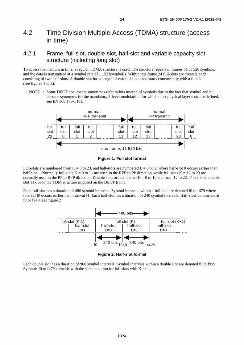
To access the medium in time, a regular TDMA structure is used. The structure repeats in frames of 11 520 symbols, and the data is transmitted at a symbol rate of 1 152 ksymbol/s. Within this frame 24 full-slots are created, each consisting of two half-slots. A double slot has a length of two full slots, and starts concurrently with a full slot (see figures 1 to 3).
NOTE 1: Some DECT documents sometimes refer to bits instead of symbols due to the fact that symbol and bit become synonyms for the mandatory 2-level modulation, for which most physical layer tests are defined, see EN 300 176-1 [9].
fullslot0
fullslot1
fullslot2
fullslot11
fullslot12
fullslot13
fullslot23
fullslot23
fullslot0
normalRFP transmit
normalPP transmit
one frame, 11 520 bits
Figure 1: Full slot format
Full-slots are numbered from K = 0 to 23, and half-slots are numbered L = 0 or 1, where half-slot 0 occurs earlier than half-slot 1. Normally full-slots K = 0 to 11 are used in the RFP to PP direction, while full slots K = 12 to 23 are normally used in the PP to RFP direction. Double slots are numbered K = 0 to 10 and from 12 to 22. There is no double slot 11 due to the TDM structure imposed on the DECT frame.
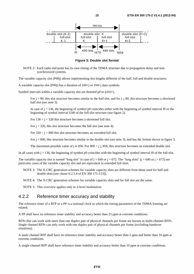
Each full-slot has a duration of 480 symbol intervals. Symbol intervals within a full-slot are denoted f0 to f479 where interval f0 occurs earlier than interval f1. Each half-slot has a duration of 240 symbol intervals. Half-slots commence at f0 or f240 (see figure 2).
full-slot (K-1)half-slot
L=1
480 bits
full-slot (K)half-slot
L=1half-slot
L=0
full-slot (K+1)half-slot
L=0
240 bits240 bitsf0 f240 f479
Figure 2: Half-slot format
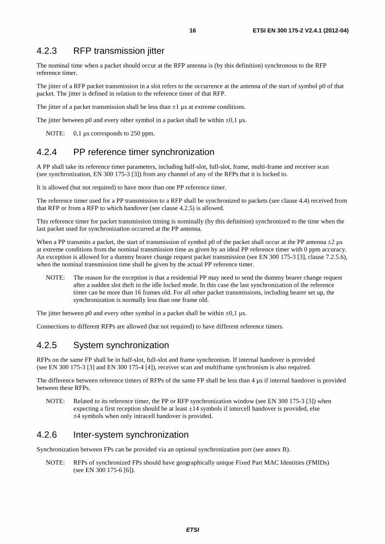
Each double slot has a duration of 960 symbol intervals. Symbol intervals within a double slot are denoted f0 to f959. Symbols f0 to f479 coincide with the same notation for full slots with K<>11.
ETSI
ETSI EN 300 175-2 V2.4.1 (2012-04) 15
d o u b l e - s l o t ( K - 2 ) f u l l - s l o t K - 1
f u l l - s l o t K + 1
f u l l - s l o t K
f u l l - s l o t K + 2
4 8 0 b i t s 4 8 0 b i t s f 0 f 4 7 9 f 9 5 9
d o u b l e - s l o t K d o u b l e - s l o t ( K + 2 )
960 bits
Figure 3: Double slot format
NOTE 2: Each radio end point has its own timing of the TDMA structure due to propagation delay and non-synchronized systems.
The variable capacity slot (P00j) allows implementing slot lengths different of the half, full and double structures.
A variable capacity slot (P00j) has a duration of 100+j or 104+j data symbols.
Symbol intervals within a variable capacity slot are denoted p0 to p103+j.
For j = 80, this slot structure becomes similar to the half slot, and for j ≤ 80, this structure becomes a shortened half slot (see note 3).
In case of j ≤ 136, the beginning of symbol p0 coincides either with the beginning of symbol interval f0 or the beginning of symbol interval f240 of the full-slot structure (see figure 2).
For 136 < j < 320 this structure becomes a shortened full slot.
For j = 320, this slot structure becomes the full slot (see note 4).
For 320 < j < 800 this slot structure becomes an extended full slot.
For j = 800, this structure becomes similar to the double slot (see note 3), and has the format shown in figure 3.
The maximum possible value of j is 856. For 800 < j ≤ 856, this structure becomes an extended double slot.
In all cases with j > 136, the beginning of symbol p0 coincides with the beginning of symbol interval f0 of the full-slot.
The variable capacity slot is named "long slot" in case of j = 640 or j = 672. The "long slots" (j = 640 or j = 672) are particular cases of the variable capacity slot and are equivalent to extended full slots.
NOTE 3: The X-CRC generation schemes for variable capacity slots are different from those used for half and double slots (see clause 6.2.5.4 of EN 300 175-3 [3]).
NOTE 4: The X-CRC generation schemes for variable capacity slots and for full slot are the same.
NOTE 5: This overview applies only to 2-level modulation.
4.2.2 Reference timer accuracy and stability
The reference timer of a RFP or a PP is a notional clock to which the timing parameters of the TDMA framing are related.
A PP shall have its reference timer stability and accuracy better than 25 ppm at extreme conditions.
RFPs that can work with more than one duplex pair of physical channels per frame are known as multi-channel RFPs. Single channel RFPs can only work with one duplex pair of physical channels per frame (excluding handover situations).
A multi channel RFP shall have its reference timer stability and accuracy better than 5 ppm and better than 10 ppm at extreme conditions.
A single channel RFP shall have reference timer stability and accuracy better than 10 ppm at extreme conditions.
ETSI
ETSI EN 300 175-2 V2.4.1 (2012-04) 16
4.2.3 RFP transmission jitter
The nominal time when a packet should occur at the RFP antenna is (by this definition) synchronous to the RFP reference timer.
The jitter of a RFP packet transmission in a slot refers to the occurrence at the antenna of the start of symbol p0 of that packet. The jitter is defined in relation to the reference timer of that RFP.
The jitter of a packet transmission shall be less than ±1 µs at extreme conditions.
The jitter between p0 and every other symbol in a packet shall be within ±0,1 µs.
NOTE: 0,1 µs corresponds to 250 ppm.
4.2.4 PP reference timer synchronization
A PP shall take its reference timer parameters, including half-slot, full-slot, frame, multi-frame and receiver scan (see synchronization, EN 300 175-3 [3]) from any channel of any of the RFPs that it is locked to.
It is allowed (but not required) to have more than one PP reference timer.
The reference timer used for a PP transmission to a RFP shall be synchronized to packets (see clause 4.4) received from that RFP or from a RFP to which handover (see clause 4.2.5) is allowed.
This reference timer for packet transmission timing is nominally (by this definition) synchronized to the time when the last packet used for synchronization occurred at the PP antenna.
When a PP transmits a packet, the start of transmission of symbol p0 of the packet shall occur at the PP antenna ±2 µs at extreme conditions from the nominal transmission time as given by an ideal PP reference timer with 0 ppm accuracy. An exception is allowed for a dummy bearer change request packet transmission (see EN 300 175-3 [3], clause 7.2.5.6), when the nominal transmission time shall be given by the actual PP reference timer.
NOTE: The reason for the exception is that a residential PP may need to send the dummy bearer change request after a sudden slot theft in the idle locked mode. In this case the last synchronization of the reference timer can be more than 16 frames old. For all other packet transmissions, including bearer set up, the synchronization is normally less than one frame old.
The jitter between p0 and every other symbol in a packet shall be within ±0,1 µs.
Connections to different RFPs are allowed (but not required) to have different reference timers.
4.2.5 System synchronization
RFPs on the same FP shall be in half-slot, full-slot and frame synchronism. If internal handover is provided (see EN 300 175-3 [3] and EN 300 175-4 [4]), receiver scan and multiframe synchronism is also required.
The difference between reference timers of RFPs of the same FP shall be less than 4 µs if internal handover is provided between these RFPs.
NOTE: Related to its reference timer, the PP or RFP synchronization window (see EN 300 175-3 [3]) when expecting a first reception should be at least ±14 symbols if intercell handover is provided, else ±4 symbols when only intracell handover is provided.
4.2.6 Inter-system synchronization
Synchronization between FPs can be provided via an optional synchronization port (see annex B).
NOTE: RFPs of synchronized FPs should have geographically unique Fixed Part MAC Identities (FMIDs) (see EN 300 175-6 [6]).
ETSI
ETSI EN 300 175-2 V2.4.1 (2012-04) 17
4.2.7 Reference timer adjustment for synchronization
To obtain system and inter-system synchronization, a RFP or PP may alter the length of a single frame by any amount, or, it may alter the length of successive frames by up to 2 symbols.
NOTE 1: Frame length alterations should be performed in accordance to the reference timer stability and accuracy requirements for RFPs and PPs as specified in clause 4.2.2.
NOTE 2: If the timing of RFPs is adjusted outside the specification of clause 4.2.2 then PPs are not expected to remain in the IDLE_LOCKED state. Therefore such timing adjustments should be made as infrequently as possible by RFP reference timers.
4.3 Cells (access in space) The third dimension to divide spectrum space is the geographical volume. Propagation losses may allow time-frequency combinations to be reused in different places.
4.4 Physical packets Data is transmitted within the frequency, time, and space dimensions using physical packets. Physical packets shall be of one of the following types:
• short physical packet P00;
• basic physical packet P32;
• low capacity physical packet P00j;
• high capacity physical packet P80.
All RFPs shall be capable of transmitting, and all PPs shall be capable of receiving, short physical packets P00. All radio end points shall be capable of transmitting and receiving at least one of the physical packet types P32, P00j, or P80.
Each physical packet contains a synchronization field S and a data field D. The packets P80, P32 and P00j may contain an optional collision detection field, Z.
4.4.1 The short physical packet P00
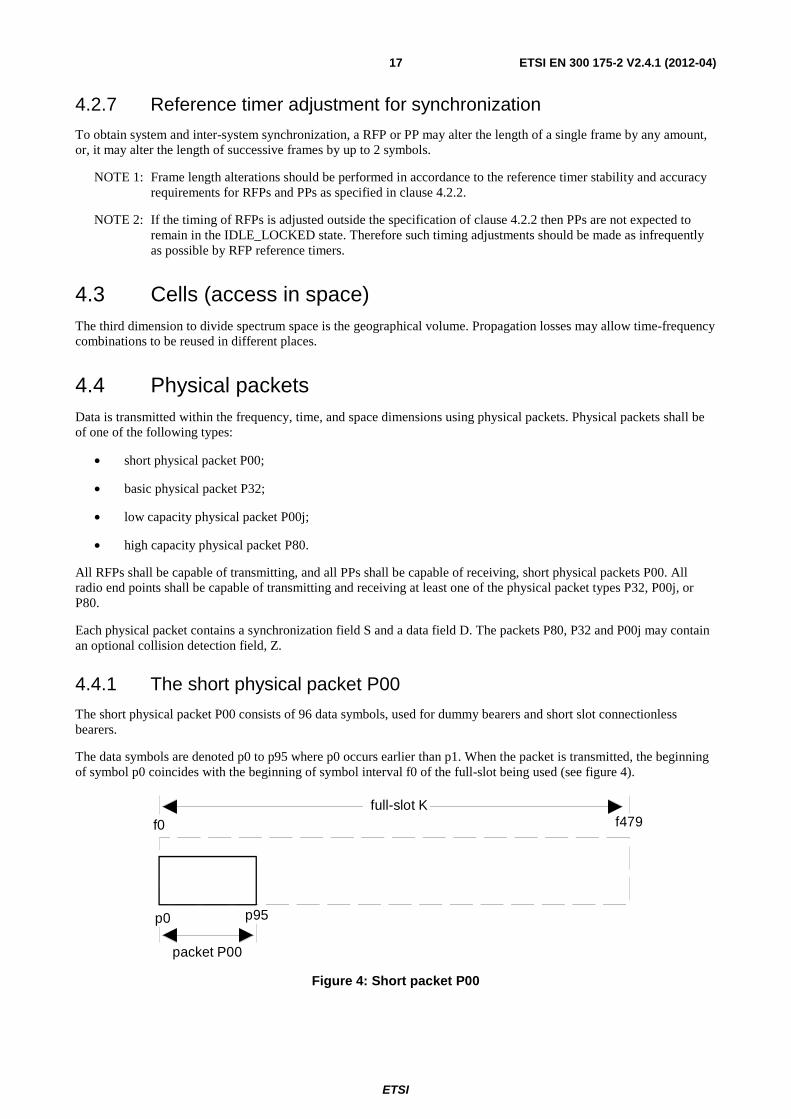
The short physical packet P00 consists of 96 data symbols, used for dummy bearers and short slot connectionless bearers.
The data symbols are denoted p0 to p95 where p0 occurs earlier than p1. When the packet is transmitted, the beginning of symbol p0 coincides with the beginning of symbol interval f0 of the full-slot being used (see figure 4).
packet P00
p0 p95
f0 f479 full-slot K
Figure 4: Short packet P00
ETSI
ETSI EN 300 175-2 V2.4.1 (2012-04) 18
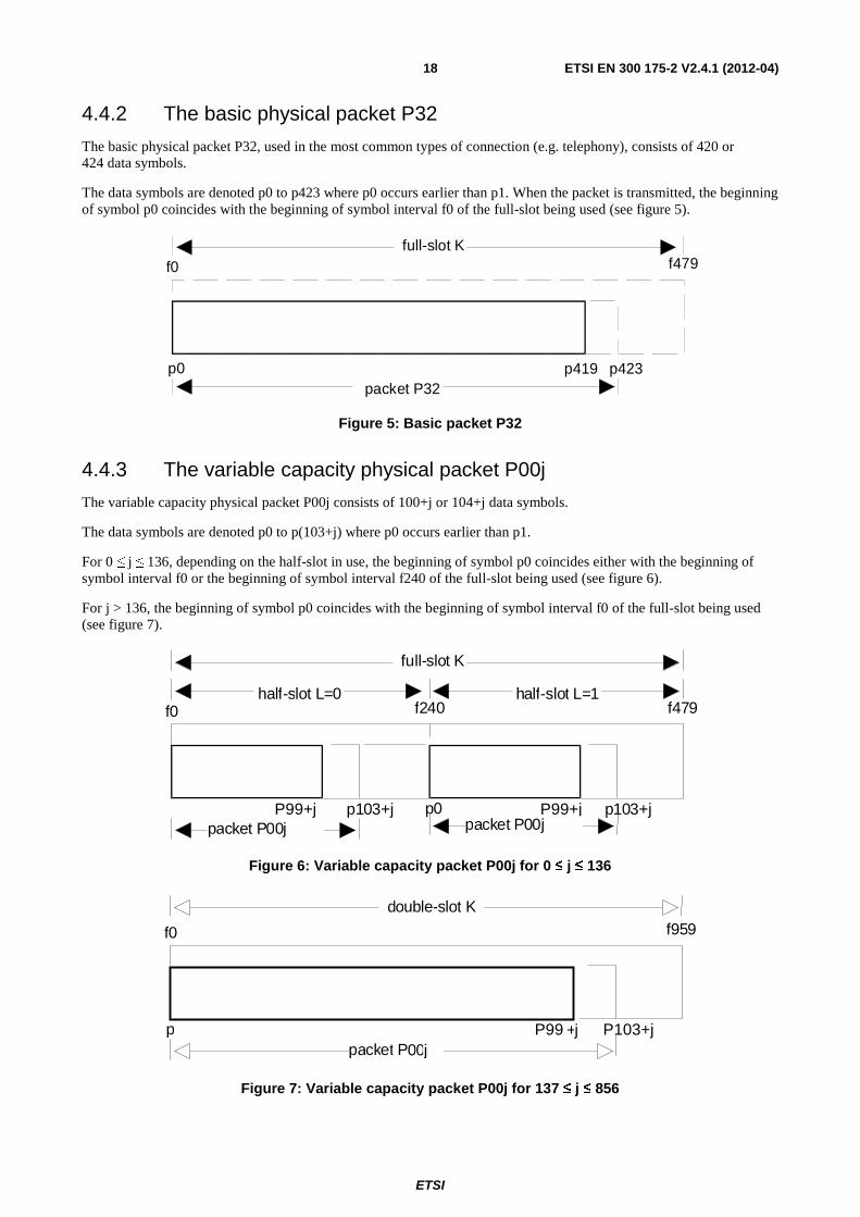
4.4.2 The basic physical packet P32
The basic physical packet P32, used in the most common types of connection (e.g. telephony), consists of 420 or 424 data symbols.
The data symbols are denoted p0 to p423 where p0 occurs earlier than p1. When the packet is transmitted, the beginning of symbol p0 coincides with the beginning of symbol interval f0 of the full-slot being used (see figure 5).
p0 p423
f0 f479 full-slot K
p419 packet P32
Figure 5: Basic packet P32
4.4.3 The variable capacity physical packet P00j
The variable capacity physical packet P00j consists of 100+j or 104+j data symbols.
The data symbols are denoted p0 to p(103+j) where p0 occurs earlier than p1.
For 0 ≤ j ≤ 136, depending on the half-slot in use, the beginning of symbol p0 coincides either with the beginning of symbol interval f0 or the beginning of symbol interval f240 of the full-slot being used (see figure 6).
For j > 136, the beginning of symbol p0 coincides with the beginning of symbol interval f0 of the full-slot being used (see figure 7).
P99+j
f0 f479 half-slot L=0
p103+j p0 P99+j p103+j packet P00j packet P00j
full-slot K
half-slot L=1 f240
Figure 6: Variable capacity packet P00j for 0 ≤ j ≤ 136
p
f0 f959
P99 +j P103+j packet P00j0j
double-slot K
Figure 7: Variable capacity packet P00j for 137 ≤ j ≤ 856
ETSI
ETSI EN 300 175-2 V2.4.1 (2012-04) 19
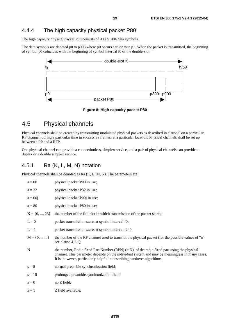
4.4.4 The high capacity physical packet P80
The high capacity physical packet P80 consists of 900 or 904 data symbols.
The data symbols are denoted p0 to p903 where p0 occurs earlier than p1. When the packet is transmitted, the beginning of symbol p0 coincides with the beginning of symbol interval f0 of the double-slot.
p0
f0 f959
p899 p903packet P80
double-slot K
Figure 8: High capacity packet P80
4.5 Physical channels Physical channels shall be created by transmitting modulated physical packets as described in clause 5 on a particular RF channel, during a particular time in successive frames, at a particular location. Physical channels shall be set up between a PP and a RFP.
One physical channel can provide a connectionless, simplex service, and a pair of physical channels can provide a duplex or a double simplex service.
4.5.1 Ra (K, L, M, N) notation
Physical channels shall be denoted as Ra (K, L, M, N). The parameters are:
a = 00 physical packet P00 in use;
a = 32 physical packet P32 in use;
a = 00j physical packet P00j in use;
a = 80 physical packet P80 in use;
K = {0, ..., 23} the number of the full-slot in which transmission of the packet starts;
L = 0 packet transmission starts at symbol interval f0;
L = 1 packet transmission starts at symbol interval f240;
M = {0, ..., n} the number of the RF channel used to transmit the physical packet (for the possible values of "n" see clause 4.1.1);
N the number, Radio fixed Part Number (RPN) (= N), of the radio fixed part using the physical channel. This parameter depends on the individual system and may be meaningless in many cases. It is, however, particularly helpful in describing handover algorithms;
s = 0 normal preamble synchronization field;
s = 16 prolonged preamble synchronization field;
z = 0 no Z field;
z = 1 Z field available.
ETSI
ETSI EN 300 175-2 V2.4.1 (2012-04) 20
NOTE: Prolonged preamble is defined in annex C. If a system employs prolonged preamble physical packets P00, P32, P00j and P80 will start at symbol p-16. Figures 8, 9, 10 and 11 are drawn for normal preamble.
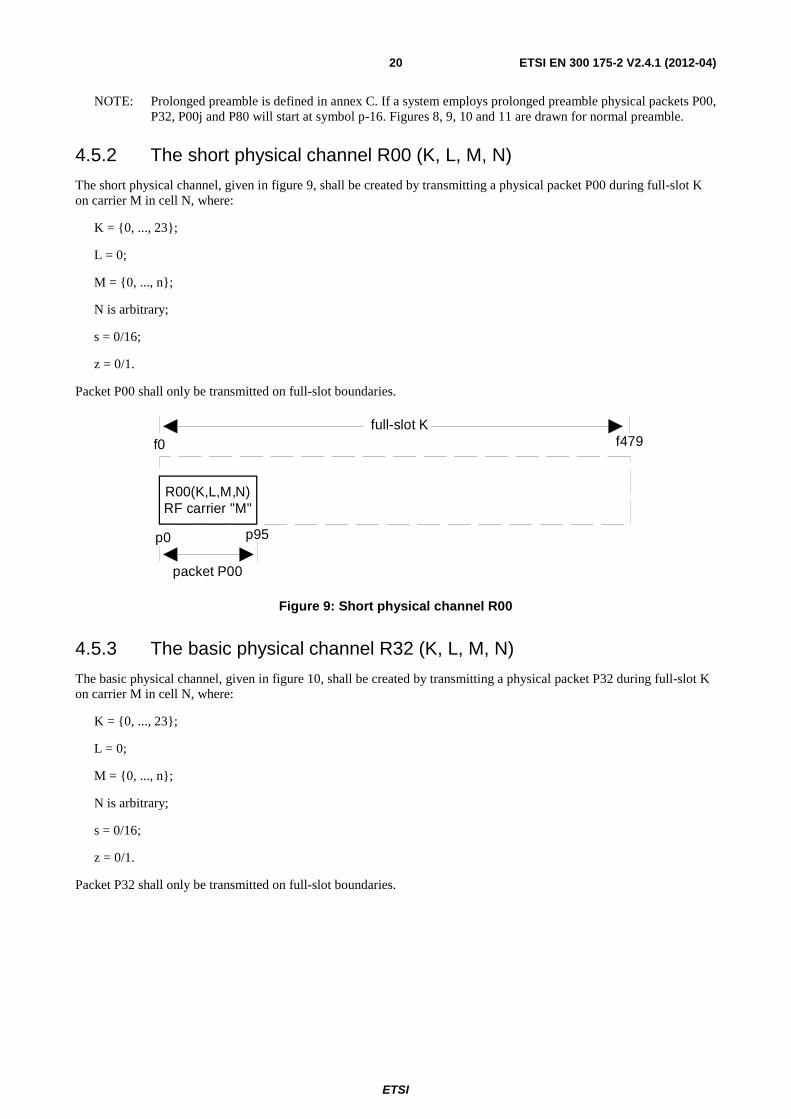
4.5.2 The short physical channel R00 (K, L, M, N)
The short physical channel, given in figure 9, shall be created by transmitting a physical packet P00 during full-slot K on carrier M in cell N, where:
K = {0, ..., 23};
L = 0;
M = {0, ..., n};
N is arbitrary;
s = 0/16;
z = 0/1.
Packet P00 shall only be transmitted on full-slot boundaries.
packet P00
p0 p95
f0 f479 full-slot K
R00(K,L,M,N)RF carrier "M"
Figure 9: Short physical channel R00
4.5.3 The basic physical channel R32 (K, L, M, N)
The basic physical channel, given in figure 10, shall be created by transmitting a physical packet P32 during full-slot K on carrier M in cell N, where:
K = {0, ..., 23};
L = 0;
M = {0, ..., n};
N is arbitrary;
s = 0/16;
z = 0/1.
Packet P32 shall only be transmitted on full-slot boundaries.
ETSI
ETSI EN 300 175-2 V2.4.1 (2012-04) 21
p0 p423
f0 f479 full-slot K
p419 packet P32
R32(K,L,M,N)RF carrier "M"
Figure 10: Basic physical channel R32
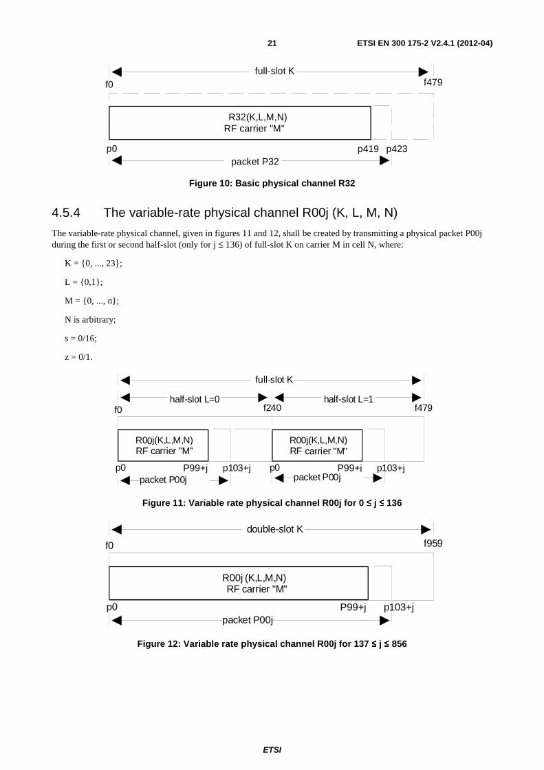
4.5.4 The variable-rate physical channel R00j (K, L, M, N)
The variable-rate physical channel, given in figures 11 and 12, shall be created by transmitting a physical packet P00j during the first or second half-slot (only for j ≤ 136) of full-slot K on carrier M in cell N, where:
K = {0, ..., 23};
L = {0,1};
M = {0, ..., n};
N is arbitrary;
s = 0/16;
z = 0/1.
p0 P99+j
f0 f479 half-slot L=0
p103+j p0 P99+j p103+j packet P00j packet P00j
full-slot K
hal f-slot L=1 f240
R00j(K,L,M ,N)RF carrier "M "
R00j(K,L,M ,N)RF carrier "M "
Figure 11: Variable rate physical channel R00j for 0 ≤ j ≤ 136
p0
f0 f959
P99+j p103+j packet P00j
double-slot K
R00j (K,L,M ,N)RF carrier "M "
Figure 12: Variable rate physical channel R00j for 137 ≤ j ≤ 856
ETSI
ETSI EN 300 175-2 V2.4.1 (2012-04) 22
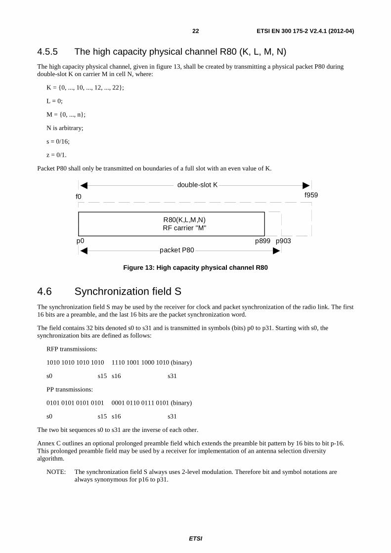
4.5.5 The high capacity physical channel R80 (K, L, M, N)
The high capacity physical channel, given in figure 13, shall be created by transmitting a physical packet P80 during double-slot K on carrier M in cell N, where:
K = {0, ..., 10, ..., 12, ..., 22};
L = 0;
M = {0, ..., n};
N is arbitrary;
s = 0/16;
z = 0/1.
Packet P80 shall only be transmitted on boundaries of a full slot with an even value of K.
p0
f0 f959
p899 p903packet P80
double-slot K
R80(K,L,M,N)RF carrier "M"
Figure 13: High capacity physical channel R80
4.6 Synchronization field S The synchronization field S may be used by the receiver for clock and packet synchronization of the radio link. The first 16 bits are a preamble, and the last 16 bits are the packet synchronization word.
The field contains 32 bits denoted s0 to s31 and is transmitted in symbols (bits) p0 to p31. Starting with s0, the synchronization bits are defined as follows:
RFP transmissions:
1010 1010 1010 1010 1110 1001 1000 1010 (binary)
s0 s15 s16 s31
PP transmissions:
0101 0101 0101 0101 0001 0110 0111 0101 (binary)
s0 s15 s16 s31
The two bit sequences s0 to s31 are the inverse of each other.
Annex C outlines an optional prolonged preamble field which extends the preamble bit pattern by 16 bits to bit p-16. This prolonged preamble field may be used by a receiver for implementation of an antenna selection diversity algorithm.
NOTE: The synchronization field S always uses 2-level modulation. Therefore bit and symbol notations are always synonymous for p16 to p31.
ETSI
ETSI EN 300 175-2 V2.4.1 (2012-04) 23
4.7 D-field
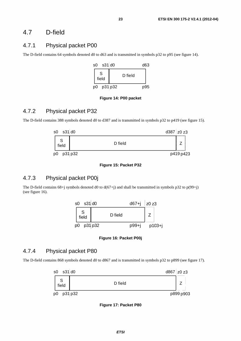
4.7.1 Physical packet P00
The D-field contains 64 symbols denoted d0 to d63 and is transmitted in symbols p32 to p95 (see figure 14).
p0
Sfield
D field
p31 p32 p95
s0 s31 d0 d63
Figure 14: P00 packet
4.7.2 Physical packet P32
The D-field contains 388 symbols denoted d0 to d387 and is transmitted in symbols p32 to p419 (see figure 15).
p0
Sfield D field
p31 p32 p419
s0 s31 d0 d387
p423
Z
z0 z3
Figure 15: Packet P32
4.7.3 Physical packet P00j
The D-field contains 68+j symbols denoted d0 to d(67+j) and shall be transmitted in symbols p32 to p(99+j) (see figure 16).
p0
Sfield D field
p31 p32 p99+j
s0 s31 d0 d67+j
p103+j
Z
z0 z3
Figure 16: Packet P00j
4.7.4 Physical packet P80
The D-field contains 868 symbols denoted d0 to d867 and is transmitted in symbols p32 to p899 (see figure 17).
p0
Sfield D field
p31 p32 p899
s0 s31 d0 d867
p903
Z
z0 z3
Figure 17: Packet P80
ETSI
ETSI EN 300 175-2 V2.4.1 (2012-04) 24
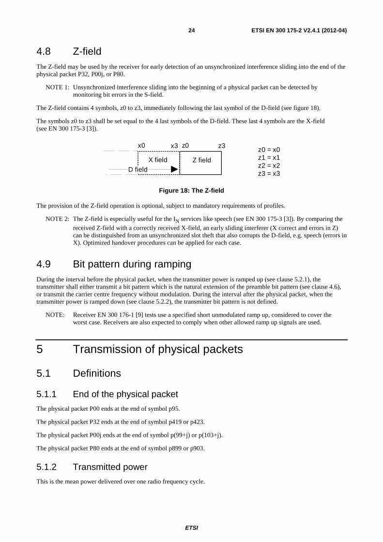
4.8 Z-field The Z-field may be used by the receiver for early detection of an unsynchronized interference sliding into the end of the physical packet P32, P00j, or P80.
NOTE 1: Unsynchronized interference sliding into the beginning of a physical packet can be detected by monitoring bit errors in the S-field.
The Z-field contains 4 symbols, z0 to z3, immediately following the last symbol of the D-field (see figure 18).
The symbols z0 to z3 shall be set equal to the 4 last symbols of the D-field. These last 4 symbols are the X-field (see EN 300 175-3 [3]).
z0 = x0z1 = x1z2 = x2z3 = x3
X field
z0 z3
Z fieldD field
x0 x3
Figure 18: The Z-field
The provision of the Z-field operation is optional, subject to mandatory requirements of profiles.
NOTE 2: The Z-field is especially useful for the IN services like speech (see EN 300 175-3 [3]). By comparing the
received Z-field with a correctly received X-field, an early sliding interferer (X correct and errors in Z) can be distinguished from an unsynchronized slot theft that also corrupts the D-field, e.g. speech (errors in X). Optimized handover procedures can be applied for each case.
4.9 Bit pattern during ramping During the interval before the physical packet, when the transmitter power is ramped up (see clause 5.2.1), the transmitter shall either transmit a bit pattern which is the natural extension of the preamble bit pattern (see clause 4.6), or transmit the carrier centre frequency without modulation. During the interval after the physical packet, when the transmitter power is ramped down (see clause 5.2.2), the transmitter bit pattern is not defined.
NOTE: Receiver EN 300 176-1 [9] tests use a specified short unmodulated ramp up, considered to cover the worst case. Receivers are also expected to comply when other allowed ramp up signals are used.
5 Transmission of physical packets
5.1 Definitions
5.1.1 End of the physical packet
The physical packet P00 ends at the end of symbol p95.
The physical packet P32 ends at the end of symbol p419 or p423.
The physical packet P00j ends at the end of symbol p(99+j) or p(103+j).
The physical packet P80 ends at the end of symbol p899 or p903.
5.1.2 Transmitted power
This is the mean power delivered over one radio frequency cycle.
ETSI
ETSI EN 300 175-2 V2.4.1 (2012-04) 25
5.1.3 Normal Transmitted Power (NTP)
The NTP is the transmitted power averaged from the start of symbol p0 of the physical packet, to the end of the physical packet.
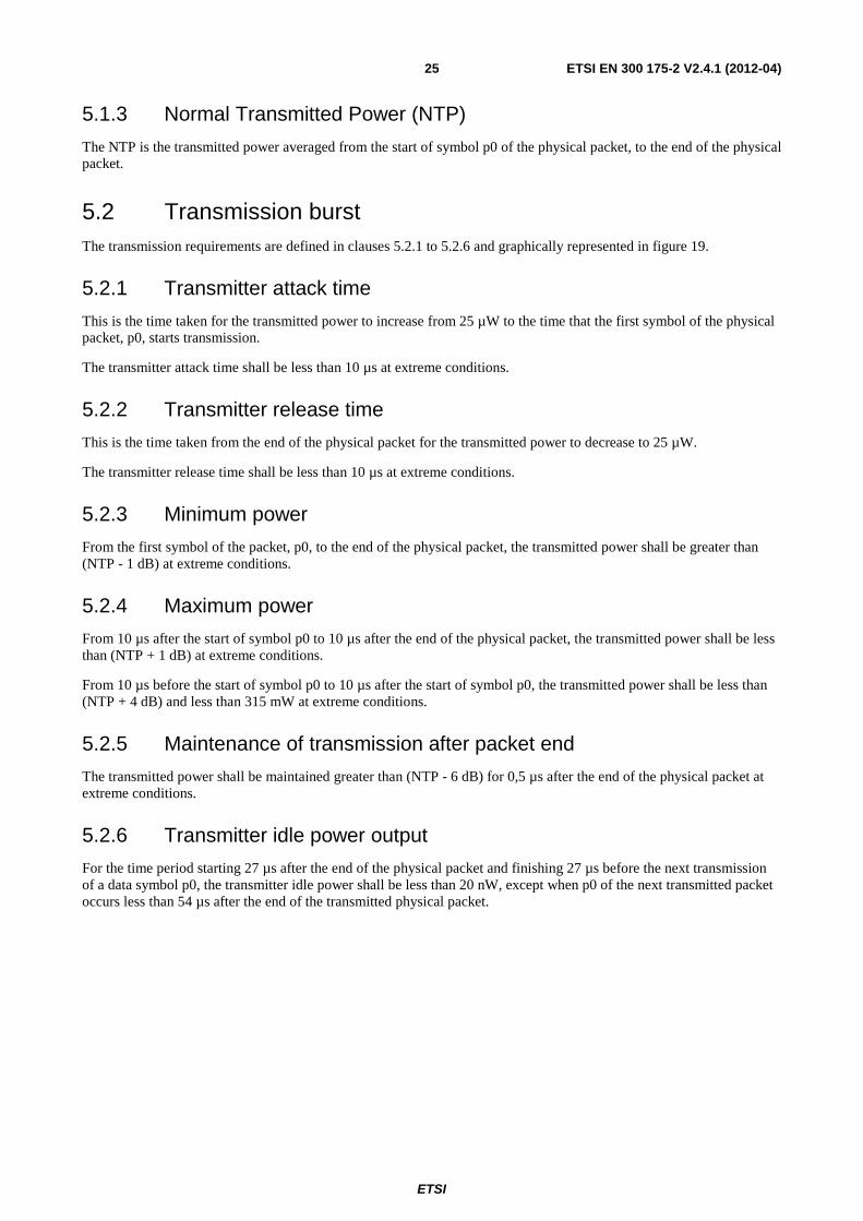
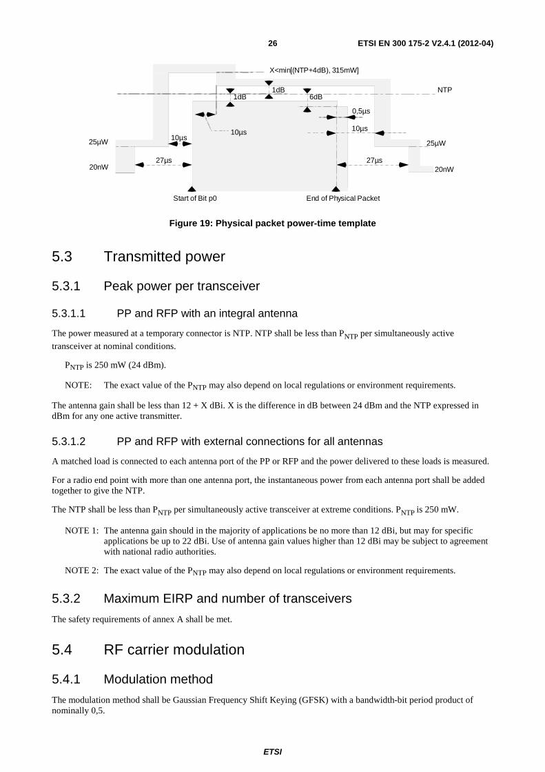
5.2 Transmission burst The transmission requirements are defined in clauses 5.2.1 to 5.2.6 and graphically represented in figure 19.
5.2.1 Transmitter attack time
This is the time taken for the transmitted power to increase from 25 µW to the time that the first symbol of the physical packet, p0, starts transmission.
The transmitter attack time shall be less than 10 µs at extreme conditions.
5.2.2 Transmitter release time
This is the time taken from the end of the physical packet for the transmitted power to decrease to 25 µW.
The transmitter release time shall be less than 10 µs at extreme conditions.
5.2.3 Minimum power
From the first symbol of the packet, p0, to the end of the physical packet, the transmitted power shall be greater than (NTP - 1 dB) at extreme conditions.
5.2.4 Maximum power
From 10 µs after the start of symbol p0 to 10 µs after the end of the physical packet, the transmitted power shall be less than (NTP + 1 dB) at extreme conditions.
From 10 µs before the start of symbol p0 to 10 µs after the start of symbol p0, the transmitted power shall be less than (NTP + 4 dB) and less than 315 mW at extreme conditions.
5.2.5 Maintenance of transmission after packet end
The transmitted power shall be maintained greater than (NTP - 6 dB) for 0,5 µs after the end of the physical packet at extreme conditions.
5.2.6 Transmitter idle power output
For the time period starting 27 µs after the end of the physical packet and finishing 27 µs before the next transmission of a data symbol p0, the transmitter idle power shall be less than 20 nW, except when p0 of the next transmitted packet occurs less than 54 µs after the end of the transmitted physical packet.
ETSI
ETSI EN 300 175-2 V2.4.1 (2012-04) 26
10µs
1dB 1dB
10µs 10µs
0 , 5 µ s
NTP
20nW
25µW 25µW
20nW
S t a r t o f Bit p0 E n d o f P h y s i c a l P a c k e t
6dB
X < m i n [ ( N T P + 4 d B ) , 3 1 5 m W ]
2 7 µ s 2 7 µ s
Figure 19: Physical packet power-time template
5.3 Transmitted power
5.3.1 Peak power per transceiver
5.3.1.1 PP and RFP with an integral antenna
The power measured at a temporary connector is NTP. NTP shall be less than PNTP per simultaneously active
transceiver at nominal conditions.
PNTP is 250 mW (24 dBm).
NOTE: The exact value of the PNTP may also depend on local regulations or environment requirements.
The antenna gain shall be less than 12 + X dBi. X is the difference in dB between 24 dBm and the NTP expressed in dBm for any one active transmitter.
5.3.1.2 PP and RFP with external connections for all antennas
A matched load is connected to each antenna port of the PP or RFP and the power delivered to these loads is measured.
For a radio end point with more than one antenna port, the instantaneous power from each antenna port shall be added together to give the NTP.
The NTP shall be less than PNTP per simultaneously active transceiver at extreme conditions. PNTP is 250 mW.
NOTE 1: The antenna gain should in the majority of applications be no more than 12 dBi, but may for specific applications be up to 22 dBi. Use of antenna gain values higher than 12 dBi may be subject to agreement with national radio authorities.
NOTE 2: The exact value of the PNTP may also depend on local regulations or environment requirements.
5.3.2 Maximum EIRP and number of transceivers
The safety requirements of annex A shall be met.
5.4 RF carrier modulation
5.4.1 Modulation method
The modulation method shall be Gaussian Frequency Shift Keying (GFSK) with a bandwidth-bit period product of nominally 0,5.
ETSI
ETSI EN 300 175-2 V2.4.1 (2012-04) 27
5.4.2 Definition of "1" and "0"
A binary "1" is encoded with a peak frequency deviation of (+f), giving a peak transmit frequency of (Fc + f), which is greater than the carrier frequency of (Fc). A binary "0" is encoded with a peak frequency deviation of (-f), giving a peak transmit frequency of (Fc - f).
The nominal peak deviation (f) shall be 288 kHz.
5.4.3 Deviation limits
The achieved deviation in any given PP or RFP may vary from this nominal value as follows:
NOTE 1: These limits apply equally to positive and negative deviations.
Case A: Case A shall apply to the transmission of a repeating binary sequence of four "1"s and four "0"s:
000011110000111100001111...
The deviation limits for case A shall be:
- peak deviation greater than 259 kHz (90 % of nominal);
- peak deviation less than 403 kHz (140 % of nominal).
Case B: Case B shall apply to the transmission of all other binary sequences (sequences both longer and shorter than case A) that contain a maximum "digital sum variation" (see note 2) with an absolute value equal to or less than sixty-four.
The deviation limits for case B shall be:
- peak deviation greater than 202 kHz (70 % of nominal);
- peak deviation less than 403 kHz (140 % of nominal).
NOTE 2: Case B includes the case of a ".1010." sequence.
NOTE 3: "Digital Sum Variation" (DSV) is defined as the cumulative total of all transmitted symbols, counted from the start of the transmission burst. A binary "1" counts as (+1); a binary "0" as (-1). The DSV total indicates the cumulative DC balance of the transmitted symbols.
5.5 Unwanted RF power radiation
5.5.1 Emissions due to modulation
With transmissions on physical channel Ra (K, L, M, N) in successive frames, the power in physical channel Ra (K, L, Y, N) shall be less than the values given in table 1.
Table 1: Emissions modulation
Emissions on RF channel "Y" Maximum power level Y = M ± 1 160 μW Y = M ± 2 1 μW Y = M ± 3 80 nW
Y = any other DECT channel 40 nW NOTE: For Y = "any other DECT channel", the maximum power level shall be less than
40 nW except for one instance of a 500 nW signal.
The power in RF channel Y is defined by integration over a bandwidth of 1 MHz centred on the nominal centre frequency, Fy, averaged over at least 60 % but less than 80 % of the physical packet, and starting before 25 of the physical packet has been transmitted but after the synchronization word.
ETSI
ETSI EN 300 175-2 V2.4.1 (2012-04) 28
5.5.2 Emissions due to transmitter transients
The power level of all modulation products (including Amplitude Modulation (AM) products due to the switching on or off of a modulated RF carrier) arising from a transmission on RF channel M shall, when measured using a peak hold technique, be less than the values given in table 2. The measurement bandwidth shall be 100 kHz and the power shall be integrated over a 1 MHz bandwidth centred on the DECT frequency, Fy.
Table 2: Emissions due to transmitter transients
Emissions on RF channel "Y" Maximum power level Y = M ± 1 250 μW Y = M ± 2 40 μW Y = M ± 3 4 μW
Y = any other DECT channel 1 μW
5.5.3 Emissions due to intermodulation
The power level of intermodulation products that are on any DECT physical channel when any combination of the transmitters at a radio end point are in calls on the same slot on different frequencies shall be less than 1 μW. The power level is defined by integration over the 1 MHz centred on the nominal centre frequency of the afflicted channel and averaged over the time period in clause 5.5.1.
5.5.4 Spurious emissions when allocated a transmit channel
The peak power level of any RF emissions outside the radio frequency band allocated to DECT, as defined in clause 4.1.1, when a radio end point has an allocated physical channel, shall not exceed 250 nW at frequencies below 1 GHz and 1 μW at frequencies above 1 GHz. The power shall be defined in the bandwidths given in table 3. If a radio end point has more than one transceiver, any out of band transmitter intermodulation products shall also be within these limits.
Table 3: Spurious emissions
Frequency offset, fo From edge of band
Measurement bandwidth
0 MHz ≤ fo < 2 MHz 30 kHz 2 MHz ≤ fo < 5 MHz 30 kHz
5 MHz ≤ fo < 10 MHz 100 kHz 10 MHz ≤ fo < 20 MHz 300 kHz 20 MHz ≤ fo < 30 MHz 1 MHz
30 MHz ≤ fo < 12,75 GHz 3 MHz
Measurements shall not be made for transmissions on the RF channel closest to the nearest band edge for frequency offsets of up to 2 MHz.
In addition, not regarding up to 2 instances of a continuous-wave spurious signal for PPs for which the total peak power level shall be less than 250 nW as measured in a 3 MHz measurement bandwidth, the peak power level shall be less than 20 nW in a 100 kHz measuring bandwidth for the following broadcast bands:
• 47 MHz to 74 MHz;
• 87,5 MHz to 108 MHz;
• 108 MHz to 118 MHz;
• 174 MHz to 230 MHz;
• 470 MHz to 862 MHz.
ETSI
ETSI EN 300 175-2 V2.4.1 (2012-04) 29
6 Reception of physical packets
6.1 Definitions and conditions for clause 6
6.1.1 Power levels and field strength
In this clause, the requirements are given in terms of power levels at the receiver input. Equipment without an external antenna connection may be taken into account by assuming that they have a 0 dBi gain antenna and converting these power level requirements into field strength requirements. This means that the tests on equipment without an external antenna will consider field strengths (E) related to the power levels (P), as specified by the following formula:
E (dBµV/m) = P (dBm) + 142,7
derived from:
E = P + 20log F (MHz) + 77,2
and assuming F = 1 890 MHz.
6.1.2 Test conditions
Steady state, non-fading conditions are assumed for both wanted and unwanted signals.
Unless otherwise stated, the frame error ratio shall be less than 5 %.
6.1.3 Reference DECT radio end point
A "reference DECT radio end point" is a DECT equipment that meets the criteria for a reference DECT radio as given in EN 300 176-1 [9]. Two of the requirements for the reference DECT radio end point are:
a) transmit power of 250 mW ± 1 dB is maintained from the beginning of bit p0 to the end of the physical packet, as defined in clause 5.1.1;
b) use of GMSK modulation with BT = 0,5, thus giving an adjacent channel interference level of 40 dB below 250 mW.
NOTE: Maximum transmit power may also depend on local regulations or environment requirements and hence be below 250 mW.
A reference DECT interferer is a continuous transmission as defined in EN 300 176-1 [9].
6.2 Radio receiver sensitivity The radio receiver sensitivity is defined as the power level at the receiver input at which the Bit Error Rate (BER) is 0,001 in the D-field.
The radio receiver sensitivity shall be -83 dBm (i.e. 60 dBμV/m), or better. This limit shall be met for a reference DECT radio end point transmitted frequency error of ±50 kHz for PPs and RFPs.
This requirement shall be met with the radio end point under test operating in time division duplex mode with a reference DECT radio end point.
Before using a DECT physical channel for transmission or reception, the receiver shall be able to measure the strength of signals on that physical channel, that are received stronger than -93 dBm (i.e. 50 dBµV/m) and weaker than -33 dBm (i.e. 110 dBµV/m) with a resolution of better than 6 dB. Signals that are received weaker than -93 dBm shall produce a result equal to, or less than that produced by a signal of -93 dBm. Signals that are received stronger than -33 dBm shall produce a result equal to, or greater than that produced by a signal of -33 dBm.
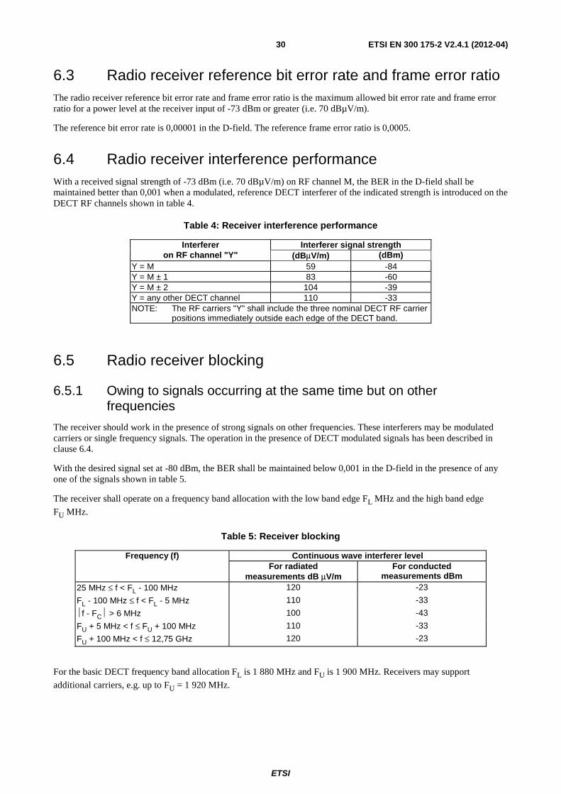
ETSI
ETSI EN 300 175-2 V2.4.1 (2012-04) 30
6.3 Radio receiver reference bit error rate and frame error ratio The radio receiver reference bit error rate and frame error ratio is the maximum allowed bit error rate and frame error ratio for a power level at the receiver input of -73 dBm or greater (i.e. 70 dBµV/m).
The reference bit error rate is 0,00001 in the D-field. The reference frame error ratio is 0,0005.
6.4 Radio receiver interference performance With a received signal strength of -73 dBm (i.e. 70 dBµV/m) on RF channel M, the BER in the D-field shall be maintained better than 0,001 when a modulated, reference DECT interferer of the indicated strength is introduced on the DECT RF channels shown in table 4.
Table 4: Receiver interference performance
Interferer Interferer signal strength on RF channel "Y" (dBμV/m) (dBm)
Y = M 59 -84 Y = M ± 1 83 -60 Y = M ± 2 104 -39 Y = any other DECT channel 110 -33 NOTE: The RF carriers "Y" shall include the three nominal DECT RF carrier
positions immediately outside each edge of the DECT band.
6.5 Radio receiver blocking
6.5.1 Owing to signals occurring at the same time but on other frequencies
The receiver should work in the presence of strong signals on other frequencies. These interferers may be modulated carriers or single frequency signals. The operation in the presence of DECT modulated signals has been described in clause 6.4.
With the desired signal set at -80 dBm, the BER shall be maintained below 0,001 in the D-field in the presence of any one of the signals shown in table 5.
The receiver shall operate on a frequency band allocation with the low band edge FL MHz and the high band edge
FU MHz.
Table 5: Receiver blocking
Frequency (f) Continuous wave interferer level For radiated
measurements dB μV/m For conducted
measurements dBm 25 MHz ≤ f < FL - 100 MHz 120 -23
FL - 100 MHz ≤ f < FL - 5 MHz 110 -33
⏐f - FC⏐ > 6 MHz 100 -43
FU + 5 MHz < f ≤ FU + 100 MHz 110 -33
FU + 100 MHz < f ≤ 12,75 GHz 120 -23
For the basic DECT frequency band allocation FL is 1 880 MHz and FU is 1 900 MHz. Receivers may support
additional carriers, e.g. up to FU = 1 920 MHz.
ETSI
ETSI EN 300 175-2 V2.4.1 (2012-04) 31
6.5.2 Owing to signals occurring at a different time
With a signal of strength -14 dBm (i.e. 129 dB/µVm) incident on the receiver in slot "N" on RF carrier "M", the receiver shall be able to receive at -83 dBm, and with the BER in the D-field maintained better than 0,001, on slot (N + 2) modulo 24 on any DECT RF carrier.
6.6 Receiver intermodulation performance With a call set up on a particular physical channel, two interferers are introduced so that they can produce an intermodulation product on the physical channel already in use.
If RF carrier number "d" is in use, a reference DECT interferer and a continuous wave interferer are introduced on DECT carriers "e" and "f" to produce an intermodulation product on carrier "d". Neither "e" nor "f" shall be adjacent to "d".
The received level of carriers "e" and "f" shall be -48 dBm and the received level of carrier "d" shall be -80 dBm.
With "e" and "f" being received 32 dB greater than "d", and "d" being received at -80 dBm, the receiver shall still operate with a BER of less than 0,001 in the D-field.
6.7 Spurious emissions when not allocated a transmit channel
6.7.1 Out of band
The power level of any spurious emissions when the radio end point has no allocated transmit channel shall not exceed 2 nW between 30 MHz and 1 GHz. Between 1 GHz and 12,75 GHz the power level shall not exceed 20 nW.
The power shall be measured using a peak hold technique with a 100 kHz measurement bandwidth.
6.7.2 In the DECT band
The power level of any spurious emissions within the DECT band shall not exceed 2 nW measured in a 1 MHz bandwidth. The following exceptions are allowed:
a) in one 1 MHz band, the maximum allowable Effective Radiated Power (ERP) shall be less than 20 nW;
b) in up to two bands of 30 kHz, the maximum ERP shall be less than 250 nW.
7 Primitives between physical layer and other entities The contents of this clause are provided for information only. This clause is aimed to assist in the description of layer-to-layer procedures.
These primitives are abstract and their concrete representations may vary from implementation to implementation. Therefore, they shall not be considered to be a testable entity.
In the parameter lists in this clause:
X = this parameter is present in this primitive;
- = this parameter is not present in this primitive;
O = this parameter is optional.
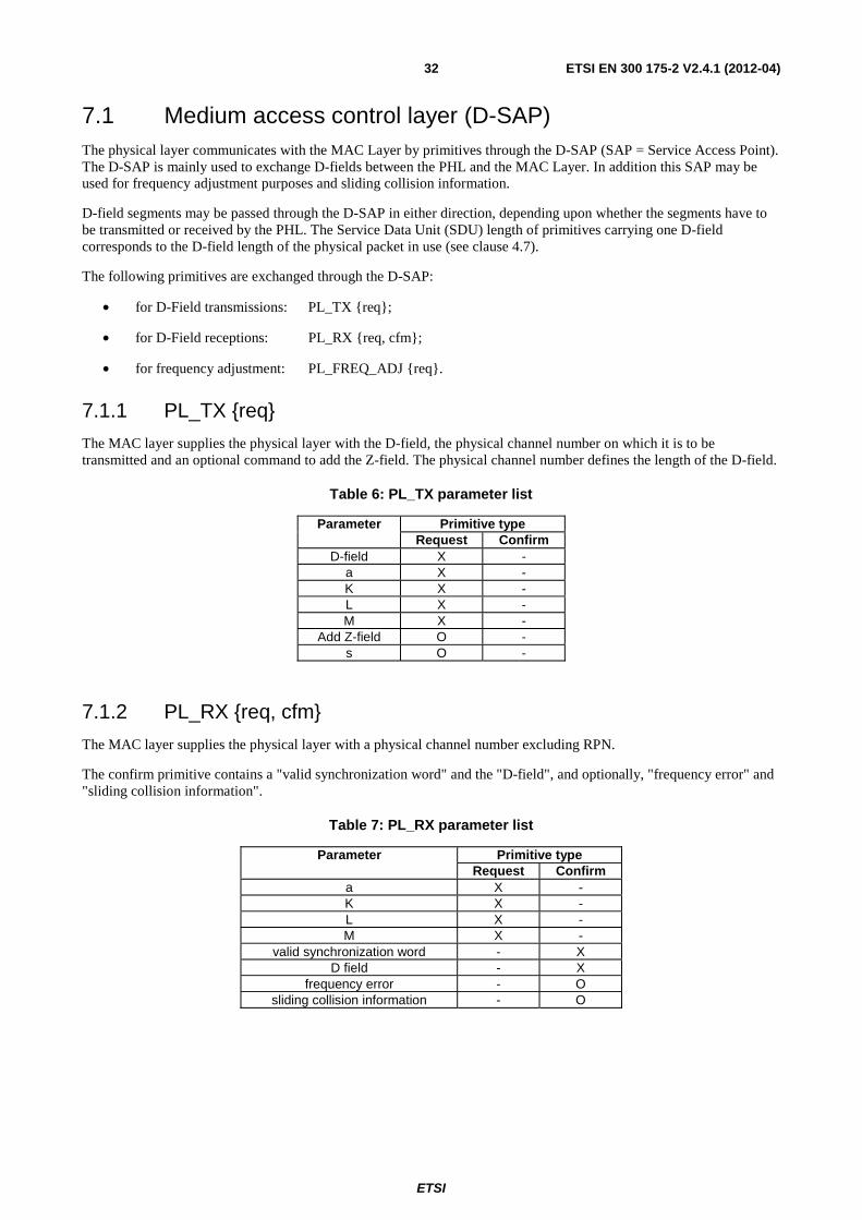
ETSI
ETSI EN 300 175-2 V2.4.1 (2012-04) 32
7.1 Medium access control layer (D-SAP) The physical layer communicates with the MAC Layer by primitives through the D-SAP (SAP = Service Access Point). The D-SAP is mainly used to exchange D-fields between the PHL and the MAC Layer. In addition this SAP may be used for frequency adjustment purposes and sliding collision information.
D-field segments may be passed through the D-SAP in either direction, depending upon whether the segments have to be transmitted or received by the PHL. The Service Data Unit (SDU) length of primitives carrying one D-field corresponds to the D-field length of the physical packet in use (see clause 4.7).
The following primitives are exchanged through the D-SAP:
• for D-Field transmissions: PL_TX {req};
• for D-Field receptions: PL_RX {req, cfm};
• for frequency adjustment: PL_FREQ_ADJ {req}.
7.1.1 PL_TX {req}
The MAC layer supplies the physical layer with the D-field, the physical channel number on which it is to be transmitted and an optional command to add the Z-field. The physical channel number defines the length of the D-field.
Table 6: PL_TX parameter list
Parameter Primitive type Request Confirm
D-field X - a X - K X - L X - M X -
Add Z-field O - s O -
7.1.2 PL_RX {req, cfm}
The MAC layer supplies the physical layer with a physical channel number excluding RPN.
The confirm primitive contains a "valid synchronization word" and the "D-field", and optionally, "frequency error" and "sliding collision information".
Table 7: PL_RX parameter list
Parameter Primitive type Request Confirm
a X - K X - L X - M X -
valid synchronization word - X D field - X
frequency error - O sliding collision information - O
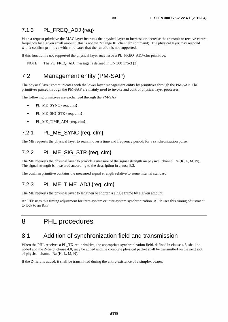
ETSI
ETSI EN 300 175-2 V2.4.1 (2012-04) 33
7.1.3 PL_FREQ_ADJ {req}
With a request primitive the MAC layer instructs the physical layer to increase or decrease the transmit or receive centre frequency by a given small amount (this is not the "change RF channel" command). The physical layer may respond with a confirm primitive which indicates that the function is not supported.
If this function is not supported the physical layer may issue a PL_FREQ_ADJ-cfm primitive.
NOTE: The PL_FREQ_ADJ message is defined in EN 300 175-3 [3].
7.2 Management entity (PM-SAP) The physical layer communicates with the lower layer management entity by primitives through the PM-SAP. The primitives passed through the PM-SAP are mainly used to invoke and control physical layer processes.
The following primitives are exchanged through the PM-SAP:
• PL_ME_SYNC {req, cfm};
• PL_ME_SIG_STR {req, cfm};
• PL_ME_TIME_ADJ {req, cfm}.
7.2.1 PL_ME_SYNC {req, cfm}
The ME requests the physical layer to search, over a time and frequency period, for a synchronization pulse.
7.2.2 PL_ME_SIG_STR {req, cfm}
The ME requests the physical layer to provide a measure of the signal strength on physical channel Ra (K, L, M, N). The signal strength is measured according to the description in clause 8.3.
The confirm primitive contains the measured signal strength relative to some internal standard.
7.2.3 PL_ME_TIME_ADJ {req, cfm}
The ME requests the physical layer to lengthen or shorten a single frame by a given amount.
An RFP uses this timing adjustment for intra-system or inter-system synchronization. A PP uses this timing adjustment to lock to an RFP.
8 PHL procedures
8.1 Addition of synchronization field and transmission When the PHL receives a PL_TX-req primitive, the appropriate synchronization field, defined in clause 4.6, shall be added and the Z-field, clause 4.8, may be added and the complete physical packet shall be transmitted on the next slot of physical channel Ra (K, L, M, N).
If the Z-field is added, it shall be transmitted during the entire existence of a simplex bearer.
ETSI
ETSI EN 300 175-2 V2.4.1 (2012-04) 34
8.2 Packet reception and removal of synchronization field When the PHL receives a PL_RX-req primitive it shall:
a) receive the specified physical packet in the next occurrence of the specified physical channel;
b) acquire and confirm slot synchronization using the synchronization field;
NOTE 1: Different parameters may be used for initial slot acquisition and slot maintenance. For example synchronization window size and required synchronization pulse height may differ.
NOTE 2: The time of the derived synchronization pulse maybe used to adjust the PP reference timer.
NOTE 3: One correlator can detect and distinguish the related PP and RFP synchronization words (see clause 4.6).
c) deliver the D-field data to the MAC layer;
NOTE 4: The size of the D-field depends on the specified physical channel.
d) optionally report the frequency error of the received channel to the MAC layer;
NOTE 5: This is used by an RFP to operate frequency control of PPs.
e) report sliding collision information to the MAC layer. This is optional subject to mandatory requirements of profiles.
NOTE 6: It is not mandatory to understand the Z-field or to have the receiver active to receive it, except when mandated in a profile. The Z-field is compared with the X-field in order to detect Z-field errors. Whether or not a Z-field is transmitted could be detected by 2 consecutive receptions of "Z-field = X-field" during the first 8 frames of a bearer transmission. Sliding collision information parameters could be "Zack" if Z = X, "Znack" if Z not equal to X, and "Zno" if the Z-field is not transmitted. Collision at the beginning of a slot can be detected by monitoring errors in the synchronization field and could be reported e.g. as "SN", where N is the number of consecutive error free bits in the last part of the preamble of the S-field, or report deviation from a "stable" N.
NOTE 7: When sliding collision indication using the Q1 bit is sent from the RFP to the PP, Q1 may be set to 1, e.g. if there are errors in the S-field or the-Z field, while the A-field is correct (see EN 300 175-3 [3], annex F).
8.3 Measurement of signal strength On receipt of a PL_ME_SIG_STR-req primitive, the physical layer measures the signal strength on the requested physical channel.
When using this primitive, the signal strength is the peak value obtained from a circuit with a time constant of between 10 µs and 40 µs.
The peak measurement shall extend over the complete packet (packet P00, P32 or P00j depending upon the intended use) and should also include a pre-packet interval of at least 10 µs and a post-packet interval of at least 10 µs.
The signal strength is integrated over a bandwidth of nominally 1 MHz centred on the received RF carrier centre frequency.
The measurement for traffic channel selections should include the prolonged preamble when the prolonged preamble is supported by FT and PT (see EN 300 175-3 [3], clause 7.2.3.5.2.2).
8.4 Synchronization pulse detection When the PHL receives a PL_ME_SYNC-req primitive, the PHL searches for a valid synchronization pulse.
ETSI
ETSI EN 300 175-2 V2.4.1 (2012-04) 35
8.5 Timing adjustment When the PHL receives a PL_ME_TIME_ADJ-req primitive, it may adjust the length of the next frame by the requested amount.
8.6 Frequency adjustment The PHL may receive a PL_FREQ_ADJ-req primitive in order to adjust its local oscillator. The PHL may react upon this primitive by adjusting its oscillator. Adjusting the oscillator shall be done within 30 ms after transmission of the PL_FREQ_ADJ message by the FT.
If this function is not supported the PHL may issue a PL_FREQ_ADJ-cfm primitive.
NOTE: The PL_FREQ_ADJ message is defined in EN 300 175-3 [3].
9 Management entity procedures related to PHL
9.1 List of quietest physical channels Using the signal strength measurements obtained with the PL_ME_SIG_STR primitives, the LLME produces an ordered list of least interfered channels.
The resolution of the signal strengths is specified in clause 6.2.
Physical channels with actual signal strengths that differ by less than this resolution may be listed in any order.
Physical channels with actual signal strengths that differ by greater than this resolution shall be listed in their actual order.
NOTE: This clause does not prevent a PP or RFP from considering the interference on physical channel pairs.
9.2 Physical channels with greatest field strength (PP only) Using the signal strength measurements obtained with the PL_ME_SIG_STR primitives, the LLME in a PP produces an ordered list of physical channels with the greatest signal strength.
The resolution of the signal strengths is specified in clause 6.2.
Physical channels with actual signal strengths that differ by less than this resolution may be listed in any order.
Physical channels with actual signal strengths that differ by greater than this resolution shall be listed in their actual order.
NOTE: This information is used with higher layer information to identify the strongest RFPs.
9.3 Extract timing Using the PL_ME_SYNC primitives, and interworking with higher layer detection of slot numbers, the LLME shall establish the slot and frame timing.
ETSI
ETSI EN 300 175-2 V2.4.1 (2012-04) 36
Annex A (informative): RF exposure requirements The content of annex A is based on or referring to the following documents:
• International Commission on Non-Ionizing Radiation Protection (ICNIRP) [i.3].
• 1999/519/EC [i.4].
• EN 50360 [i.5].
• EN 50385 [i.6].
• EN 50383 [i.7].
A.1 Recommendation In areas accessible for the general public, the RF exposure should not exceed the power density reference level at 1 800 MHz, which is 9 W/m2 averaged over a period of 6 min. The reference level can be exceeded if the basic SAR (Specific Absorption Rate, W/kg) restrictions are met. The SAR requirements are:
a) the whole-body averaged SAR should not exceed 0,08 W/kg;
b) the localized SAR averaged over any 10 gram of tissue should not exceed 2,0 W/kg, except for the limbs (arms, legs, hands, feet), where the maximum SAR is 4,0 W/kg.
All of the SAR limits are averaged over 6 min.
A.2 Compliance distances Compliance distance means the minimum recommended distance of any part of the body to the antenna.
In any exposure situation, SAR is directly proportional to the mean output power from the antenna. For low-power devices like DECT equipment, the compliance distances are therefore very short, usually less than a few centimetres. This is true for both low- and high-gain antennas. Since high-gain antennas usually have larger size and lower near-field exposure levels, the SAR levels are often lower than for low-gain antennas.
The following compliance distances are recommended for DECT equipment:
a) Portable Part (PP). The maximum average power is 10 mW (RMS) for handsets (speech and low rate messaging). Below 20 mW the whole-body and localized partial-body SAR limits cannot be exceeded and the equipment is deemed to be in compliance with the recommended basic restrictions at all distances. See EN 50360 [i.5]. For portable parts with higher data rates, for example multi bearer higher data rate PCMCIA cards, the maximum average power is for most devices no more than 60 mW (RMS). At this power level the whole-body SAR limit cannot be exceeded and the maximum localized partial-body SAR is usually below the limit at all distances, i.e. no compliance distance is needed. No device will have an average power exceeding 250 mW (RMS). At such low power level, the whole-body averaged SAR limit cannot be exceeded. Typically, the localized partial-body SAR is also well below the limit at distances smaller than 5 cm. Presently, a test standard is only available for handsets, but not for devices like PCMCIA cards, PCs and PDAs. See however requirements and tests for Radio Fixed Parts (base stations).
ETSI
ETSI EN 300 175-2 V2.4.1 (2012-04) 37
b) Radio Fixed Part (RFP) (residential). The maximum average power is typically no more than 60 mW (RMS) (6 simultaneous full slot bearer transmissions). At this power level the whole-body SAR limit cannot be exceeded and the maximum localized partial-body SAR is usually below the limit at all distances, i.e. no compliance distance is needed. This can be verified using the test methods specified in EN 50383 [i.7]. In active idle mode (only a dummy bearer) the average power is no more than 2,5 mW and the RF exposure limits cannot be exceeded.
c) Radio Fixed Part (RFP) (general). The maximum average power is 250 mW (RMS). At such low power level, the whole-body averaged SAR limit cannot be exceeded. For most types of antennas, the localized partial-body SAR is also below the limit at distances smaller than 5 cm. The compliance distance can be determined by SAR measurements using the procedures specified in EN 50383 [i.7].
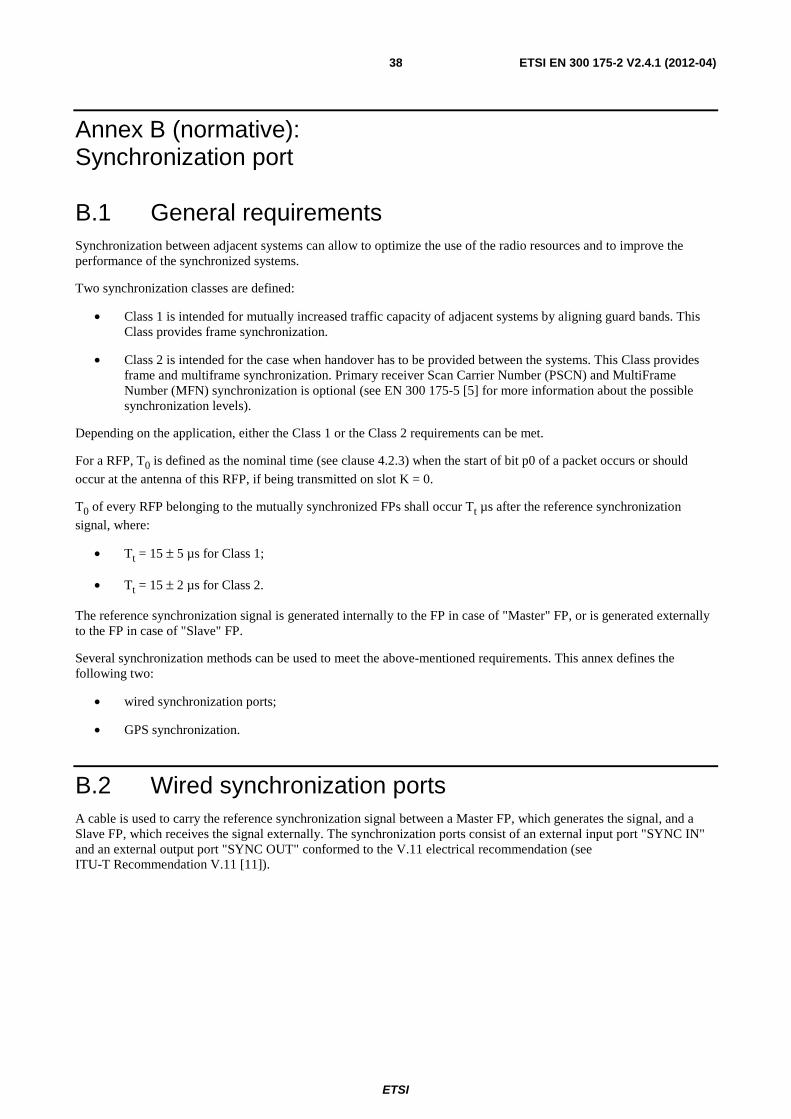
ETSI
ETSI EN 300 175-2 V2.4.1 (2012-04) 38
Annex B (normative): Synchronization port
B.1 General requirements Synchronization between adjacent systems can allow to optimize the use of the radio resources and to improve the performance of the synchronized systems.
Two synchronization classes are defined:
• Class 1 is intended for mutually increased traffic capacity of adjacent systems by aligning guard bands. This Class provides frame synchronization.
• Class 2 is intended for the case when handover has to be provided between the systems. This Class provides frame and multiframe synchronization. Primary receiver Scan Carrier Number (PSCN) and MultiFrame Number (MFN) synchronization is optional (see EN 300 175-5 [5] for more information about the possible synchronization levels).
Depending on the application, either the Class 1 or the Class 2 requirements can be met.
For a RFP, T0 is defined as the nominal time (see clause 4.2.3) when the start of bit p0 of a packet occurs or should
occur at the antenna of this RFP, if being transmitted on slot K = 0.
T0 of every RFP belonging to the mutually synchronized FPs shall occur Tt µs after the reference synchronization
signal, where:
• Tt = 15 ± 5 µs for Class 1;
• Tt = 15 ± 2 µs for Class 2.
The reference synchronization signal is generated internally to the FP in case of "Master" FP, or is generated externally to the FP in case of "Slave" FP.
Several synchronization methods can be used to meet the above-mentioned requirements. This annex defines the following two:
• wired synchronization ports;
• GPS synchronization.
B.2 Wired synchronization ports A cable is used to carry the reference synchronization signal between a Master FP, which generates the signal, and a Slave FP, which receives the signal externally. The synchronization ports consist of an external input port "SYNC IN" and an external output port "SYNC OUT" conformed to the V.11 electrical recommendation (see ITU-T Recommendation V.11 [11]).
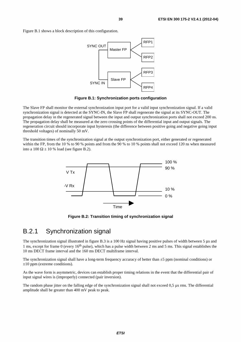
ETSI
ETSI EN 300 175-2 V2.4.1 (2012-04) 39
Figure B.1 shows a block description of this configuration.
SYNC OUT
SYNC IN
Master FP
Slave FP
RFP1
RFP2
RFP3
RFP4
Figure B.1: Synchronization ports configuration
The Slave FP shall monitor the external synchronization input port for a valid input synchronization signal. If a valid synchronization signal is detected at the SYNC-IN, the Slave FP shall regenerate the signal at its SYNC-OUT. The propagation delay in the regenerated signal between the input and output synchronization ports shall not exceed 200 ns. The propagation delay shall be measured at the zero crossing points of the differential input and output signals. The regeneration circuit should incorporate input hysteresis (the difference between positive going and negative going input threshold voltages) of nominally 50 mV.
The transition times of the synchronization signal at the output synchronization port, either generated or regenerated within the FP, from the 10 % to 90 % points and from the 90 % to 10 % points shall not exceed 120 ns when measured into a 100 Ω ± 10 % load (see figure B.2).
V Tx
-V Rx
100 % 90 %
10 %
0 %
Time
Figure B.2: Transition timing of synchronization signal
B.2.1 Synchronization signal The synchronization signal illustrated in figure B.3 is a 100 Hz signal having positive pulses of width between 5 μs and 1 ms, except for frame 0 (every 16th pulse), which has a pulse width between 2 ms and 5 ms. This signal establishes the 10 ms DECT frame interval and the 160 ms DECT multiframe interval.
The synchronization signal shall have a long-term frequency accuracy of better than ±5 ppm (nominal conditions) or ±10 ppm (extreme conditions).
As the wave form is asymmetric, devices can establish proper timing relations in the event that the differential pair of input signal wires is (improperly) connected (pair inversion).
The random phase jitter on the falling edge of the synchronization signal shall not exceed 0,5 µs rms. The differential amplitude shall be greater than 400 mV peak to peak.
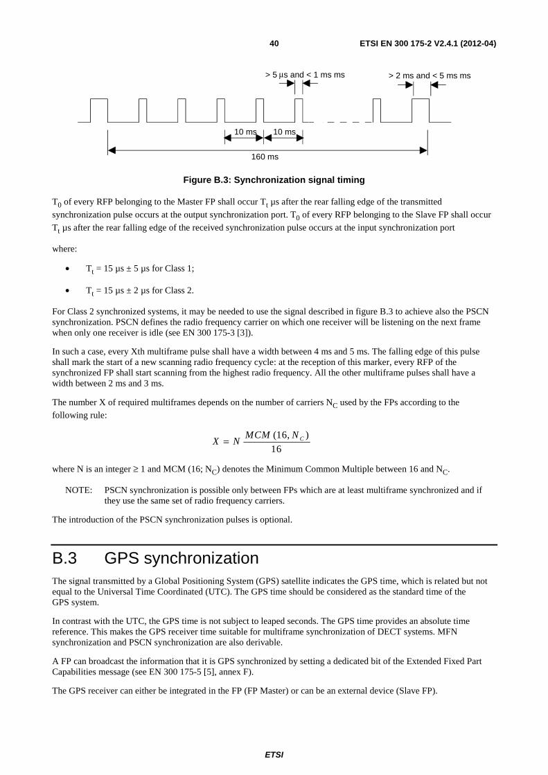
ETSI
ETSI EN 300 175-2 V2.4.1 (2012-04) 40
10 ms 10 ms
160 ms
> 5 μ s and < 1 ms ms > 2 ms and < 5 ms ms
Figure B.3: Synchronization signal timing
T0 of every RFP belonging to the Master FP shall occur Tt µs after the rear falling edge of the transmitted
synchronization pulse occurs at the output synchronization port. T0 of every RFP belonging to the Slave FP shall occur
Tt µs after the rear falling edge of the received synchronization pulse occurs at the input synchronization port
where:
• Tt = 15 µs ± 5 µs for Class 1;
• Tt = 15 µs ± 2 µs for Class 2.
For Class 2 synchronized systems, it may be needed to use the signal described in figure B.3 to achieve also the PSCN synchronization. PSCN defines the radio frequency carrier on which one receiver will be listening on the next frame when only one receiver is idle (see EN 300 175-3 [3]).
In such a case, every Xth multiframe pulse shall have a width between 4 ms and 5 ms. The falling edge of this pulse shall mark the start of a new scanning radio frequency cycle: at the reception of this marker, every RFP of the synchronized FP shall start scanning from the highest radio frequency. All the other multiframe pulses shall have a width between 2 ms and 3 ms.
The number X of required multiframes depends on the number of carriers NC used by the FPs according to the
following rule:
X NMCM N C= ( , )16
16
where N is an integer ≥ 1 and MCM (16; NC) denotes the Minimum Common Multiple between 16 and NC.
NOTE: PSCN synchronization is possible only between FPs which are at least multiframe synchronized and if they use the same set of radio frequency carriers.
The introduction of the PSCN synchronization pulses is optional.
B.3 GPS synchronization The signal transmitted by a Global Positioning System (GPS) satellite indicates the GPS time, which is related but not equal to the Universal Time Coordinated (UTC). The GPS time should be considered as the standard time of the GPS system.
In contrast with the UTC, the GPS time is not subject to leaped seconds. The GPS time provides an absolute time reference. This makes the GPS receiver time suitable for multiframe synchronization of DECT systems. MFN synchronization and PSCN synchronization are also derivable.
A FP can broadcast the information that it is GPS synchronized by setting a dedicated bit of the Extended Fixed Part Capabilities message (see EN 300 175-5 [5], annex F).
The GPS receiver can either be integrated in the FP (FP Master) or can be an external device (Slave FP).
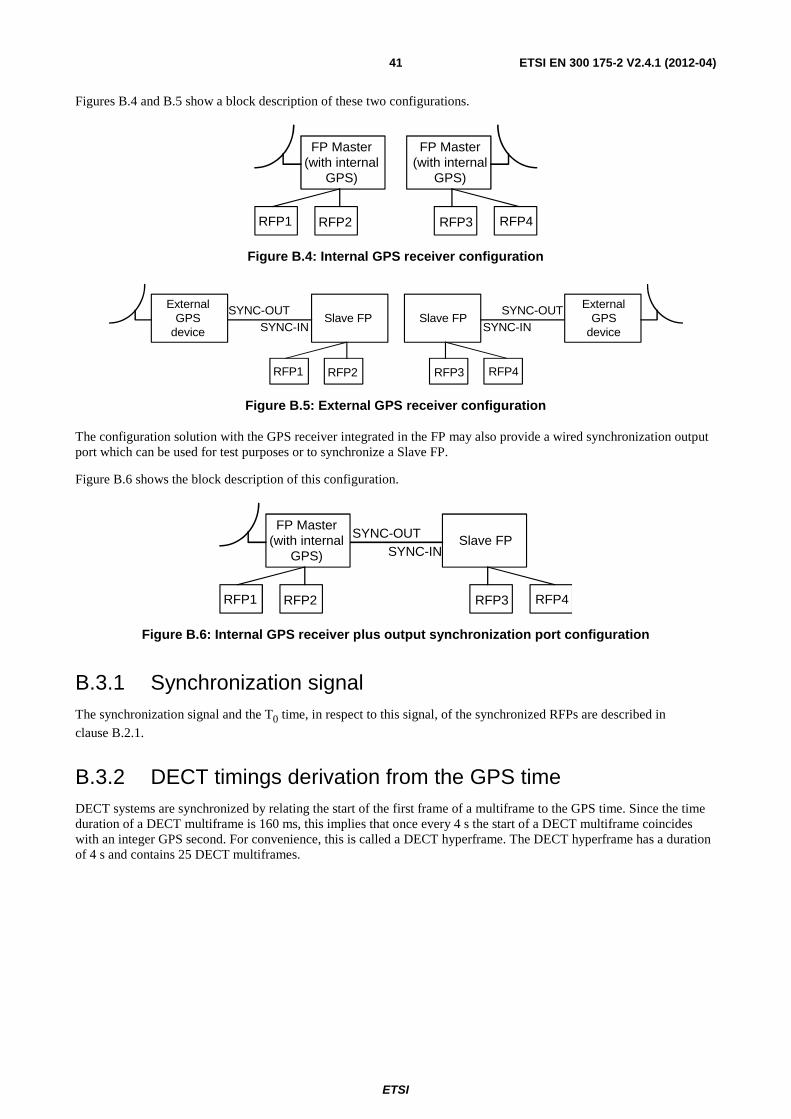
ETSI
ETSI EN 300 175-2 V2.4.1 (2012-04) 41
Figures B.4 and B.5 show a block description of these two configurations.
FP Master(with internal
GPS)
RFP1 RFP2
FP Master(with internal
GPS)
RFP4RFP3
Figure B.4: Internal GPS receiver configuration
Slave FP
RFP1 RFP2
ExternalGPS
device
SYNC-OUTSYNC-IN
Slave FP
RFP4RFP3
ExternalGPS
device
SYNC-OUTSYNC-IN
Figure B.5: External GPS receiver configuration
The configuration solution with the GPS receiver integrated in the FP may also provide a wired synchronization output port which can be used for test purposes or to synchronize a Slave FP.
Figure B.6 shows the block description of this configuration.
FP Master(with internal
GPS)
RFP1 RFP2
Slave FP
RFP4RFP3
SYNC-OUTSYNC-IN
Figure B.6: Internal GPS receiver plus output synchronization port configuration
B.3.1 Synchronization signal The synchronization signal and the T0 time, in respect to this signal, of the synchronized RFPs are described in
clause B.2.1.
B.3.2 DECT timings derivation from the GPS time DECT systems are synchronized by relating the start of the first frame of a multiframe to the GPS time. Since the time duration of a DECT multiframe is 160 ms, this implies that once every 4 s the start of a DECT multiframe coincides with an integer GPS second. For convenience, this is called a DECT hyperframe. The DECT hyperframe has a duration of 4 s and contains 25 DECT multiframes.
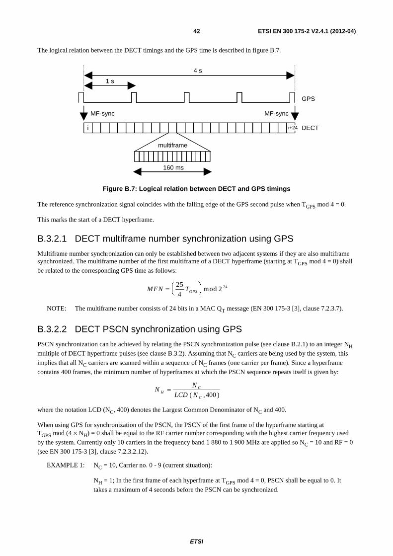
ETSI
ETSI EN 300 175-2 V2.4.1 (2012-04) 42
The logical relation between the DECT timings and the GPS time is described in figure B.7.
4 s
1 s
MF-sync
GPS
DECT
multiframe
160 ms
MF-sync
i i+24
Figure B.7: Logical relation between DECT and GPS timings
The reference synchronization signal coincides with the falling edge of the GPS second pulse when TGPS mod 4 = 0.
This marks the start of a DECT hyperframe.
B.3.2.1 DECT multiframe number synchronization using GPS
Multiframe number synchronization can only be established between two adjacent systems if they are also multiframe synchronized. The multiframe number of the first multiframe of a DECT hyperframe (starting at TGPS mod 4 = 0) shall
be related to the corresponding GPS time as follows:
MFN TGPS= ⎛⎝⎜
⎞⎠⎟
25
42 24mod
NOTE: The multiframe number consists of 24 bits in a MAC QT message (EN 300 175-3 [3], clause 7.2.3.7).
B.3.2.2 DECT PSCN synchronization using GPS
PSCN synchronization can be achieved by relating the PSCN synchronization pulse (see clause B.2.1) to an integer NH
multiple of DECT hyperframe pulses (see clause B.3.2). Assuming that NC carriers are being used by the system, this
implies that all NC carriers are scanned within a sequence of NC frames (one carrier per frame). Since a hyperframe
contains 400 frames, the minimum number of hyperframes at which the PSCN sequence repeats itself is given by:
NN
LCD NHC
C
=( , )400
where the notation LCD (NC, 400) denotes the Largest Common Denominator of NC and 400.
When using GPS for synchronization of the PSCN, the PSCN of the first frame of the hyperframe starting at TGPS mod (4 × NH) = 0 shall be equal to the RF carrier number corresponding with the highest carrier frequency used
by the system. Currently only 10 carriers in the frequency band 1 880 to 1 900 MHz are applied so NC = 10 and RF = 0
(see EN 300 175-3 [3], clause 7.2.3.2.12).
EXAMPLE 1: NC = 10, Carrier no. 0 - 9 (current situation):
NH = 1; In the first frame of each hyperframe at TGPS mod 4 = 0, PSCN shall be equal to 0. It
takes a maximum of 4 seconds before the PSCN can be synchronized.
ETSI
ETSI EN 300 175-2 V2.4.1 (2012-04) 43
EXAMPLE 2: NC = 13, Carrier no. 17 - 29 (fictitious future situation):
NH = 13; In the first frame of each hyperframe at TGPS mod 52 = 0 PSCN shall be equal to 29. It
takes a maximum of 52 s before the PSCN can be synchronized.
B.4 Guidance for installation
B.4.1 Interconnection cable Where interconnecting cable is used to provide synchronization between systems or devices to be synchronized, it shall provide two independent signal paths, neither of which is grounded. The type and length of interconnecting cable used for synchronization shall ensure that during the transition period, the signal wave form (measured at the input synchronization port) shall change monotonically between the 10 % and 90 % points and shall not cross the 10 % and 90 % thresholds again until the next state transition point. The interconnection cable shall ensure that the input signal meets the requirements of clause B.2.1.
B.4.2 Propagation delay of synchronization signals
B.4.2.1 Calculation of Propagation delay (informative)
The purpose of this informative clause is to show a derivation of the maximum synchronization signal propagation delay, and to illustrate the trade off between the number of devices which may be connected in a cluster and the total length of interconnecting cable.
Let the maximum propagation delay of the synchronization signal from the first device in a cluster to the final device be Dmax. The time Dmax is derived as follows:
D = G - J - S - T max
where:
G = guard time;
J = portable timing jitter;
S = synchronization accuracy;
T = ramp down time.
The maximum number of regenerations, Rmax, with no cable delay is:
RD
Tregmaxmax=
where:
Treg = regeneration delay in a device (= 200 ns, see clause B.2).
The maximum cable length, Lmax, with no regenerations, is given by:
Lmax = C × VF × Dmax
where:
C = speed of light (= 3 × 10⁸ m/s);
VF = cable velocity factor (= in the range 0,6 to 0,7).
ETSI
ETSI EN 300 175-2 V2.4.1 (2012-04) 44
This calculation indicates the maximum total length of cable between two devices to be synchronized. The maximum practical length for an individual section of cable between two devices will also be restricted by transmission line effects (see clause B.4.1).
Neither the maximum cable length nor the maximum number of regenerations derived above will be achievable in any practical system. There will always be a trade-off between the number of synchronized devices or systems (i.e. regenerations) and the length of cable needed to interconnect them.
B.4.2.2 Delay compensation
In order to compensate for installation dependent synchronization signal delays (e.g. as a result of cable propagation delays) between devices to be synchronized, it is recommended that it be possible for slave devices to be capable of adjusting Tt (see clause B.1) between 0 µs and 20 µs to a resolution of at least ±1 µs. Means of making this timing
adjustment shall be provided by Class 2 equipment.
B.4.3 GPS receiver stability In order to provide synchronous external handover, it is recommended that the time accuracy of the GPS receiver should be at least within ±1 µs from the logical TGPS time.
ETSI
ETSI EN 300 175-2 V2.4.1 (2012-04) 45
Annex C (informative): Prolonged preamble Implementing this provision is optional.
Prolonged preamble transmissions are intended to be used in combination with a preamble switched antenna instant receiver selection diversity algorithm implemented at the receiving end. This algorithm implies that the receiver during a first part of the preamble makes a first link quality estimate using one antenna, and during a second part makes a second estimate using the other antenna, and then, for a third (the last) part of the preamble and the rest of the packet, selects the antenna which gave the highest quality estimate. This algorithm can provide a performance improvement corresponding to 10 dB increased link budget in a mobile or moving environment. Traditional means to provide this performance improvement requires two complete radio receivers. The prolonged preamble helps implementing low-cost and efficient means for the quality estimates needed in the algorithm.
NOTE 1: Normal procedures carried out during the preamble when this algorithm is implemented will thus be sliding slot detection, bit synchronization, two quality estimations and two antenna switching.
NOTE 2: The MT "Quality control" advance timing command message is intended to facilitate the implementation
of the prolonged preamble option for distances beyond 1 km (see EN 300 175-3 [3], clause 7.2.5.5, command 0110).
C.1 Bit pattern The extension of the preamble is 16 bits, s-16 to s-1, and the bit pattern is a continuous advance extension of the bit patterns defined for the preamble in clause 4.6, Synchronization field S.
RFP transmissions: 1010 1010 1010 1010
s-16 s-1
PP transmissions: 0101 0101 0101 0101
s-16 s-1
C.2 The power-time template Packets with prolonged preamble are subject to the definitions and requirements of clauses 5.1 and 5.2 with the notation p0 generally changed to p-16.
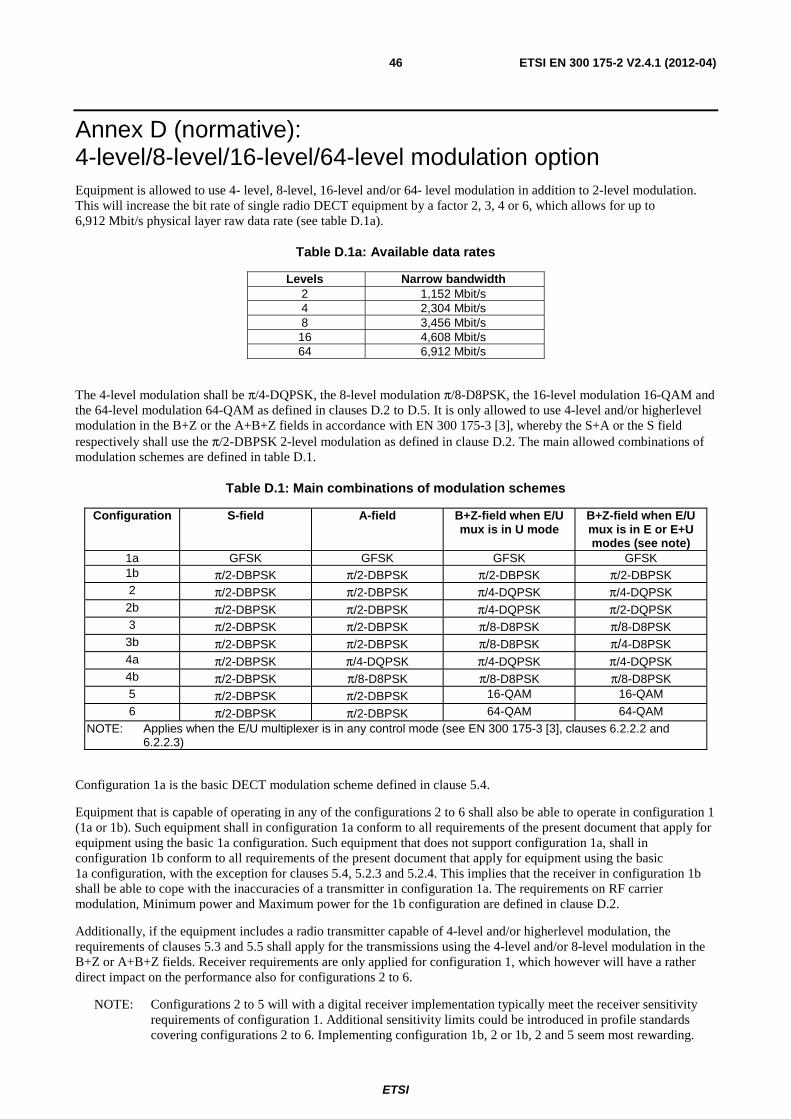
ETSI
ETSI EN 300 175-2 V2.4.1 (2012-04) 46
Annex D (normative): 4-level/8-level/16-level/64-level modulation option Equipment is allowed to use 4- level, 8-level, 16-level and/or 64- level modulation in addition to 2-level modulation. This will increase the bit rate of single radio DECT equipment by a factor 2, 3, 4 or 6, which allows for up to 6,912 Mbit/s physical layer raw data rate (see table D.1a).
Table D.1a: Available data rates
Levels Narrow bandwidth 2 1,152 Mbit/s 4 2,304 Mbit/s 8 3,456 Mbit/s 16 4,608 Mbit/s 64 6,912 Mbit/s
The 4-level modulation shall be π/4-DQPSK, the 8-level modulation π/8-D8PSK, the 16-level modulation 16-QAM and the 64-level modulation 64-QAM as defined in clauses D.2 to D.5. It is only allowed to use 4-level and/or higherlevel modulation in the B+Z or the A+B+Z fields in accordance with EN 300 175-3 [3], whereby the S+A or the S field respectively shall use the π/2-DBPSK 2-level modulation as defined in clause D.2. The main allowed combinations of modulation schemes are defined in table D.1.
Table D.1: Main combinations of modulation schemes
Configuration S-field A-field B+Z-field when E/U mux is in U mode
B+Z-field when E/U mux is in E or E+U modes (see note)
1a GFSK GFSK GFSK GFSK 1b π/2-DBPSK π/2-DBPSK π/2-DBPSK π/2-DBPSK 2 π/2-DBPSK π/2-DBPSK π/4-DQPSK π/4-DQPSK
2b π/2-DBPSK π/2-DBPSK π/4-DQPSK π/2-DQPSK 3 π/2-DBPSK π/2-DBPSK π/8-D8PSK π/8-D8PSK
3b π/2-DBPSK π/2-DBPSK π/8-D8PSK π/4-D8PSK 4a π/2-DBPSK π/4-DQPSK π/4-DQPSK π/4-DQPSK 4b π/2-DBPSK π/8-D8PSK π/8-D8PSK π/8-D8PSK 5 π/2-DBPSK π/2-DBPSK 16-QAM 16-QAM
6 π/2-DBPSK π/2-DBPSK 64-QAM 64-QAM NOTE: Applies when the E/U multiplexer is in any control mode (see EN 300 175-3 [3], clauses 6.2.2.2 and
6.2.2.3)
Configuration 1a is the basic DECT modulation scheme defined in clause 5.4.
Equipment that is capable of operating in any of the configurations 2 to 6 shall also be able to operate in configuration 1 (1a or 1b). Such equipment shall in configuration 1a conform to all requirements of the present document that apply for equipment using the basic 1a configuration. Such equipment that does not support configuration 1a, shall in configuration 1b conform to all requirements of the present document that apply for equipment using the basic 1a configuration, with the exception for clauses 5.4, 5.2.3 and 5.2.4. This implies that the receiver in configuration 1b shall be able to cope with the inaccuracies of a transmitter in configuration 1a. The requirements on RF carrier modulation, Minimum power and Maximum power for the 1b configuration are defined in clause D.2.
Additionally, if the equipment includes a radio transmitter capable of 4-level and/or higherlevel modulation, the requirements of clauses 5.3 and 5.5 shall apply for the transmissions using the 4-level and/or 8-level modulation in the B+Z or A+B+Z fields. Receiver requirements are only applied for configuration 1, which however will have a rather direct impact on the performance also for configurations 2 to 6.
NOTE: Configurations 2 to 5 will with a digital receiver implementation typically meet the receiver sensitivity requirements of configuration 1. Additional sensitivity limits could be introduced in profile standards covering configurations 2 to 6. Implementing configuration 1b, 2 or 1b, 2 and 5 seem most rewarding.
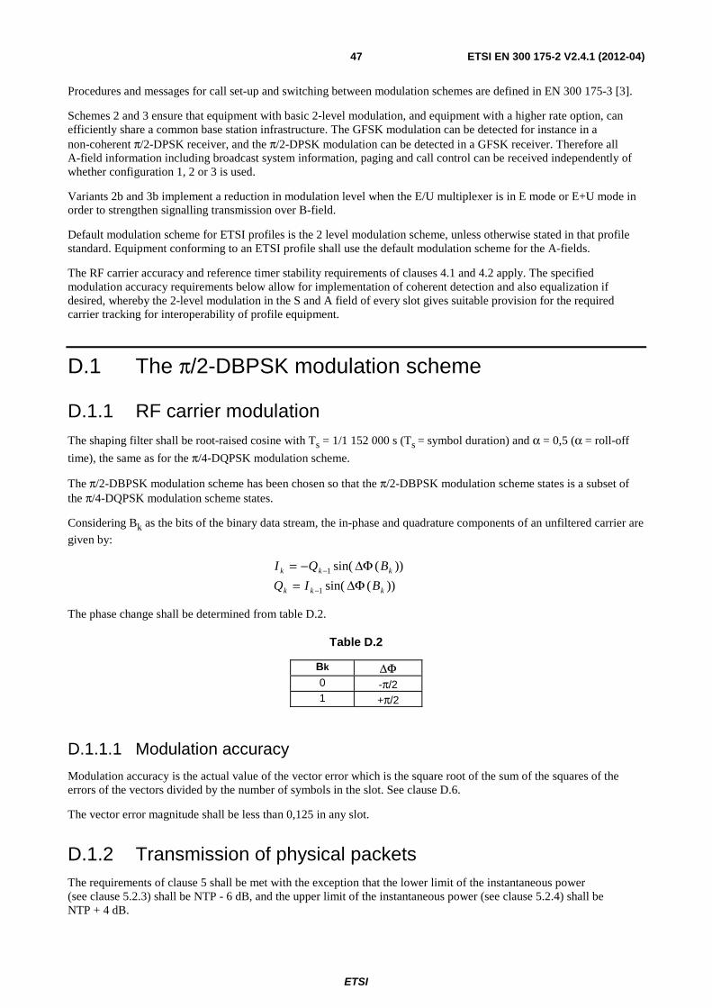
ETSI
ETSI EN 300 175-2 V2.4.1 (2012-04) 47
Procedures and messages for call set-up and switching between modulation schemes are defined in EN 300 175-3 [3].
Schemes 2 and 3 ensure that equipment with basic 2-level modulation, and equipment with a higher rate option, can efficiently share a common base station infrastructure. The GFSK modulation can be detected for instance in a non-coherent π/2-DPSK receiver, and the π/2-DPSK modulation can be detected in a GFSK receiver. Therefore all A-field information including broadcast system information, paging and call control can be received independently of whether configuration 1, 2 or 3 is used.
Variants 2b and 3b implement a reduction in modulation level when the E/U multiplexer is in E mode or E+U mode in order to strengthen signalling transmission over B-field.
Default modulation scheme for ETSI profiles is the 2 level modulation scheme, unless otherwise stated in that profile standard. Equipment conforming to an ETSI profile shall use the default modulation scheme for the A-fields.
The RF carrier accuracy and reference timer stability requirements of clauses 4.1 and 4.2 apply. The specified modulation accuracy requirements below allow for implementation of coherent detection and also equalization if desired, whereby the 2-level modulation in the S and A field of every slot gives suitable provision for the required carrier tracking for interoperability of profile equipment.
D.1 The π/2-DBPSK modulation scheme
D.1.1 RF carrier modulation The shaping filter shall be root-raised cosine with Ts = 1/1 152 000 s (Ts = symbol duration) and α = 0,5 (α = roll-off
time), the same as for the π/4-DQPSK modulation scheme.
The π/2-DBPSK modulation scheme has been chosen so that the π/2-DBPSK modulation scheme states is a subset of the π/4-DQPSK modulation scheme states.
Considering Bk as the bits of the binary data stream, the in-phase and quadrature components of an unfiltered carrier are
given by:
))(sin(
))(sin(
1
1
kkk
kkk
BIQ
BQI
ΔΦ=ΔΦ−=
−
−
The phase change shall be determined from table D.2.
Table D.2
Bk ΔΦ 0 -π/2 1 +π/2
D.1.1.1 Modulation accuracy
Modulation accuracy is the actual value of the vector error which is the square root of the sum of the squares of the errors of the vectors divided by the number of symbols in the slot. See clause D.6.
The vector error magnitude shall be less than 0,125 in any slot.
D.1.2 Transmission of physical packets The requirements of clause 5 shall be met with the exception that the lower limit of the instantaneous power (see clause 5.2.3) shall be NTP - 6 dB, and the upper limit of the instantaneous power (see clause 5.2.4) shall be NTP + 4 dB.
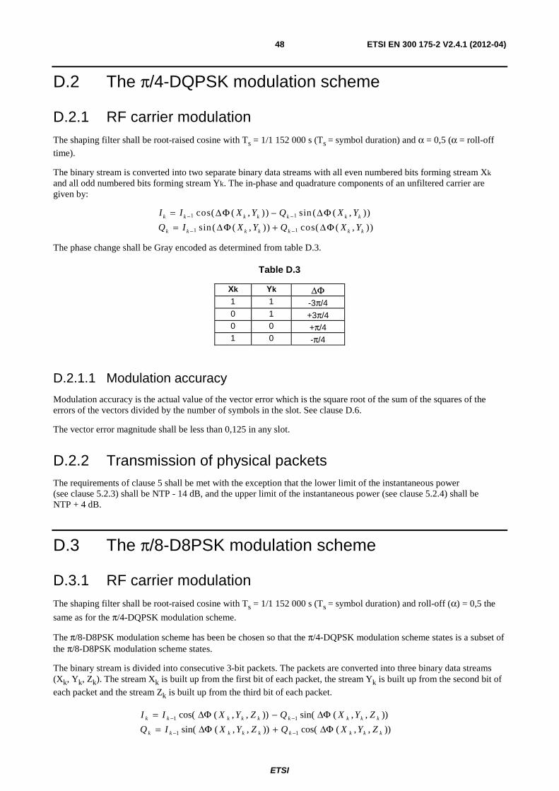
ETSI
ETSI EN 300 175-2 V2.4.1 (2012-04) 48
D.2 The π/4-DQPSK modulation scheme
D.2.1 RF carrier modulation The shaping filter shall be root-raised cosine with Ts = 1/1 152 000 s (Ts = symbol duration) and α = 0,5 (α = roll-off
time).
The binary stream is converted into two separate binary data streams with all even numbered bits forming stream Xk and all odd numbered bits forming stream Yk. The in-phase and quadrature components of an unfiltered carrier are given by:
I I X Y Q X Y
Q I X Y Q X Y k k k k k k k
k k k k k k k
= −= +
− −
− −
1 1
1 1
cos ( ( , ) ) sin ( ( , ) )
sin ( ( , ) ) cos ( ( , ) )
ΔΦ ΔΦΔΦ ΔΦ
The phase change shall be Gray encoded as determined from table D.3.
Table D.3
Xk Yk ΔΦ 1 1 -3π/4 0 1 +3π/4 0 0 +π/4 1 0 -π/4
D.2.1.1 Modulation accuracy
Modulation accuracy is the actual value of the vector error which is the square root of the sum of the squares of the errors of the vectors divided by the number of symbols in the slot. See clause D.6.
The vector error magnitude shall be less than 0,125 in any slot.
D.2.2 Transmission of physical packets The requirements of clause 5 shall be met with the exception that the lower limit of the instantaneous power (see clause 5.2.3) shall be NTP - 14 dB, and the upper limit of the instantaneous power (see clause 5.2.4) shall be NTP + 4 dB.
D.3 The π/8-D8PSK modulation scheme
D.3.1 RF carrier modulation The shaping filter shall be root-raised cosine with Ts = 1/1 152 000 s (Ts = symbol duration) and roll-off (α) = 0,5 the
same as for the π/4-DQPSK modulation scheme.
The π/8-D8PSK modulation scheme has been be chosen so that the π/4-DQPSK modulation scheme states is a subset of the π/8-D8PSK modulation scheme states.
The binary stream is divided into consecutive 3-bit packets. The packets are converted into three binary data streams (Xk, Yk, Zk). The stream Xk is built up from the first bit of each packet, the stream Yk is built up from the second bit of
each packet and the stream Zk is built up from the third bit of each packet.
)),,(cos()),,(sin(
)),,(sin()),,(cos(
11
11
kkkkkkkkk
kkkkkkkkk
ZYXQZYXIQ
ZYXQZYXII
ΔΦ+ΔΦ=ΔΦ−ΔΦ=
−−
−−
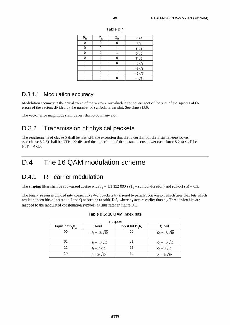
ETSI
ETSI EN 300 175-2 V2.4.1 (2012-04) 49
Table D.4
Xk Yk Zk ΔΦ 0 0 0 π/8 0 0 1 3π/8 0 1 1 5π/8 0 1 0 7π/8 1 1 0 - 7π/8 1 1 1 - 5π/8 1 0 1 - 3π/8 1 0 0 - π/8
D.3.1.1 Modulation accuracy
Modulation accuracy is the actual value of the vector error which is the square root of the sum of the squares of the errors of the vectors divided by the number of symbols in the slot. See clause D.6.
The vector error magnitude shall be less than 0,06 in any slot.
D.3.2 Transmission of physical packets The requirements of clause 5 shall be met with the exception that the lower limit of the instantaneous power (see clause 5.2.3) shall be NTP - 22 dB, and the upper limit of the instantaneous power (see clause 5.2.4) shall be NTP + 4 dB.
D.4 The 16 QAM modulation scheme
D.4.1 RF carrier modulation The shaping filter shall be root-raised cosine with Ts = 1/1 152 000 s (Ts = symbol duration) and roll-off (α) = 0,5.
The binary stream is divided into consecutive 4-bit packets by a serial to parallel conversion which uses four bits which result in index bits allocated to I and Q according to table D.5, where b1 occurs earlier than b2. These index bits are
mapped to the modulated constellation symbols as illustrated in figure D.1.
Table D.5: 16 QAM index bits
16 QAM Input bit b1b2 I-out Input bit b3b4 Q-out
00 10/33 −=− I 00 10/33 −=− Q
01 10/11 −=− I 01 10/11 −=− Q 11 10/11 =I 11 10/11 =Q 10 10/33 =I 10 10/33 =Q
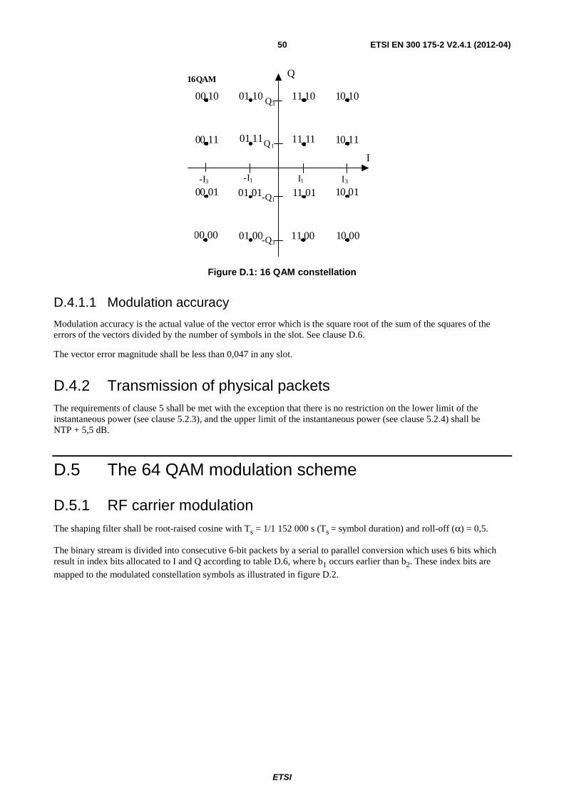
ETSI
ETSI EN 300 175-2 V2.4.1 (2012-04) 50
I
10 00 11 00 01 00 00 00
10 01
10 11
11 01 01 01 00 01
10 10 11 10
00 11
01 10 00 10
11 11 01 11
16QAM
I1
Q
I3
Q3
Q1
-Q1
-Q3
-I1 -I3
Figure D.1: 16 QAM constellation
D.4.1.1 Modulation accuracy
Modulation accuracy is the actual value of the vector error which is the square root of the sum of the squares of the errors of the vectors divided by the number of symbols in the slot. See clause D.6.
The vector error magnitude shall be less than 0,047 in any slot.
D.4.2 Transmission of physical packets The requirements of clause 5 shall be met with the exception that there is no restriction on the lower limit of the instantaneous power (see clause 5.2.3), and the upper limit of the instantaneous power (see clause 5.2.4) shall be NTP + 5,5 dB.
D.5 The 64 QAM modulation scheme
D.5.1 RF carrier modulation The shaping filter shall be root-raised cosine with Ts = 1/1 152 000 s (Ts = symbol duration) and roll-off (α) = 0,5.
The binary stream is divided into consecutive 6-bit packets by a serial to parallel conversion which uses 6 bits which result in index bits allocated to I and Q according to table D.6, where b1 occurs earlier than b2. These index bits are
mapped to the modulated constellation symbols as illustrated in figure D.2.
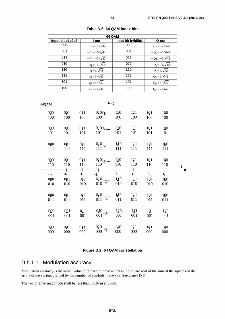
ETSI
ETSI EN 300 175-2 V2.4.1 (2012-04) 51
Table D.6: 64 QAM index bits
64 QAM Input bit b1b2b3 I-out Input bit b4b5b6 Q-out
000 42/77 −=− I 000 42/77 −=− Q
001 42/55 −=− I 001 42/55 −=− Q
011 42/33 −=− I 011 42/33 −=− Q
010 42/11 −=− I 010 42/11 −=− Q 110 42/11 =I 110 42/11 =Q 111 42/33 =I 111 42/33 =Q
101 42/55 =I 101 42/55 =Q
100 42/77 =I 100 42/77 =Q
100 000
101 000
111 000
110 000
010 000
011 000
001 000
000 000
100 001
101 001
111 001
110 001
010 001
011 001
001 001
000 001
100 011
101 011
111 011
110 011
010 011
011 011
001 011
000 011
100 01 0
101 010
111 010
110 010
010 010
011 010
001 010
000 010
100 110
101 110
111 110
110 110
010 110
011 110
001 110
000 110
100 111
101 111
111 111
110 111
010 111
011 111
001 111
000 111
100 101
101 101
111 101
110 101
010 101
0 11 101
001 101
000 101
100 100
101 100
111 100
110 100
010 100
011 100
001 100
000 100
64QAM Q
I
I1 I3 I5 I7 -I1 -I3 -I5 -I7
Q1
Q3
Q5
Q7
-Q1
-Q3
-Q5
-Q7
Figure D.2: 64 QAM constellation
D.5.1.1 Modulation accuracy
Modulation accuracy is the actual value of the vector error which is the square root of the sum of the squares of the errors of the vectors divided by the number of symbols in the slot. See clause D.6.
The vector error magnitude shall be less than 0,026 in any slot.
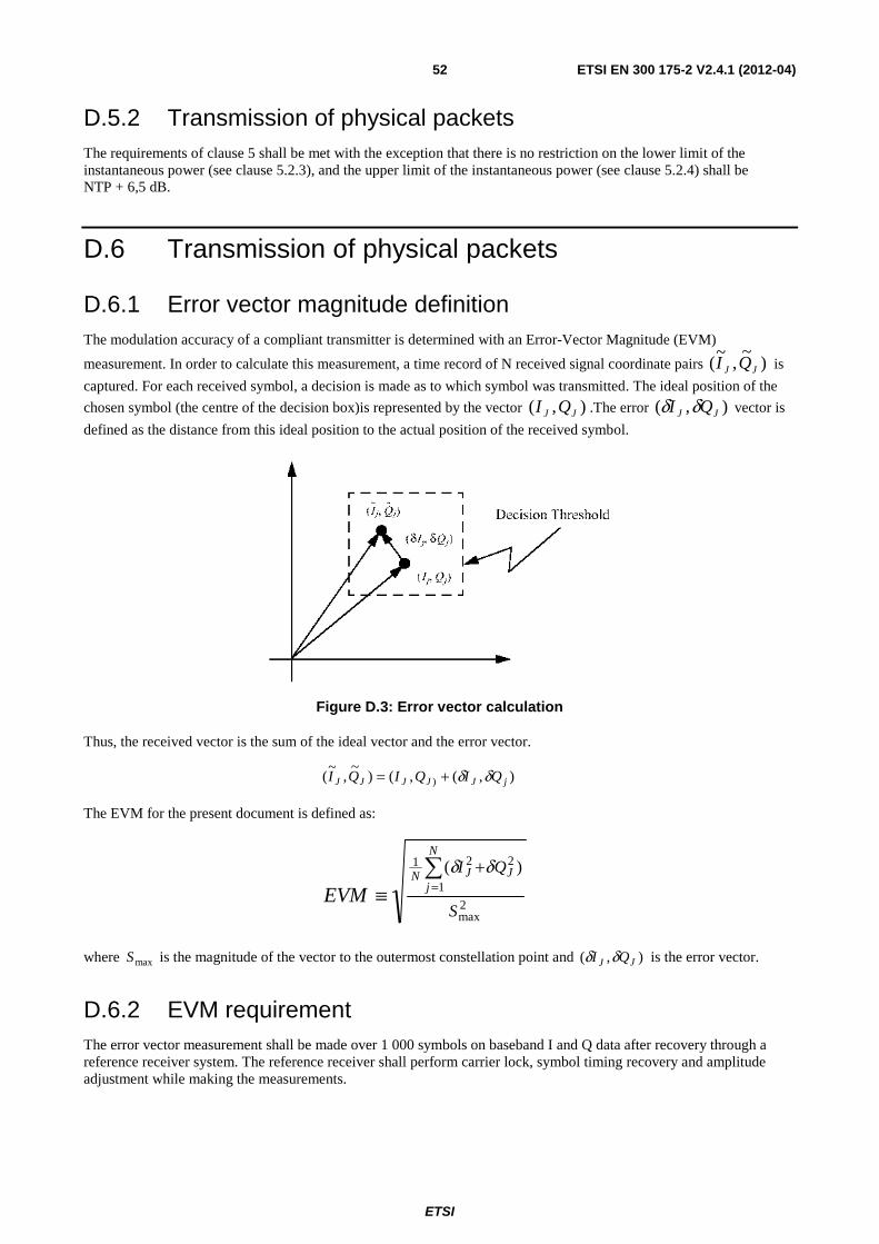
ETSI
ETSI EN 300 175-2 V2.4.1 (2012-04) 52
D.5.2 Transmission of physical packets The requirements of clause 5 shall be met with the exception that there is no restriction on the lower limit of the instantaneous power (see clause 5.2.3), and the upper limit of the instantaneous power (see clause 5.2.4) shall be NTP + 6,5 dB.
D.6 Transmission of physical packets
D.6.1 Error vector magnitude definition The modulation accuracy of a compliant transmitter is determined with an Error-Vector Magnitude (EVM)
measurement. In order to calculate this measurement, a time record of N received signal coordinate pairs )~
,~
( JJ QI is
captured. For each received symbol, a decision is made as to which symbol was transmitted. The ideal position of the
chosen symbol (the centre of the decision box)is represented by the vector ),( JJ QI .The error ),( JJ QI δδ vector is
defined as the distance from this ideal position to the actual position of the received symbol.
Figure D.3: Error vector calculation
Thus, the received vector is the sum of the ideal vector and the error vector.
),(,()~
,~
( ) jJJJJJ QIQIQI δδ+=
The EVM for the present document is defined as:
2max
2
1
21 )(
S
QI J
N
jJN
EVM∑
=+
≡δδ
where maxS is the magnitude of the vector to the outermost constellation point and ),( JJ QI δδ is the error vector.
D.6.2 EVM requirement The error vector measurement shall be made over 1 000 symbols on baseband I and Q data after recovery through a reference receiver system. The reference receiver shall perform carrier lock, symbol timing recovery and amplitude adjustment while making the measurements.
ETSI
ETSI EN 300 175-2 V2.4.1 (2012-04) 53
Annex E (normative): Power control procedures Annex E describes optional DECT power control capabilities. Power control capabilities for DECT have to be defined with care so that the functionality of the basic DECT procedures for instant Dynamic Channel Selection, iDCS, is not jeopardized. For this reason, power control cannot be implemented for RFPs and the procedures for PP power control have to be carefully defined.
NOTE: DECT RFP per connection down-link power control is not possible due to the iDCS procedure. It is however possible to have a static reduced power for all down-link transmissions from a specific FP. A DECT system may have the same reduced power on all RFPs, or have different power on different RFPs which will result in different "cell sizes". (However different cell sizes will due to the iDCS procedures automatically occur just by having different separation distances between RFPs, without any need for different RFP power levels.) Information on static reduced RFP power may be broadcast by the FP. See clause E.3 and EN 300 175-3 [3], clause 7.2.4.3.10.
The DECT PP power control is designed to provide similar RFP receive power for all up-links within a cell. The procedures are designed to compensate for changes in the link budget (due to PP movement) and not for changes during a call of the interference level. Interference is counteracted by handover to a less interfered bearer.
By introducing PP power control the average PP transmitter power will be decreased. This will reduce the average PP power consumption and increase the talk time correspondingly. PP power control will, due to the constant RFP power, principally not decrease bearer interference between (synchronized) cells within a multi-cell system. Substantial traffic enhancements would however result within "cells" with co-located RFPs and WRSs or multi radio RFPs and WRSs, and within sectored WLL RFP sites.
The procedures below are for open loop power control, where the PP controls the power without power control commands from the RFP. An optional broadcast PT message informing on the (static) RFP power level is however available. This is helpful if the RFPs use (static) power settings below 24 dBm.
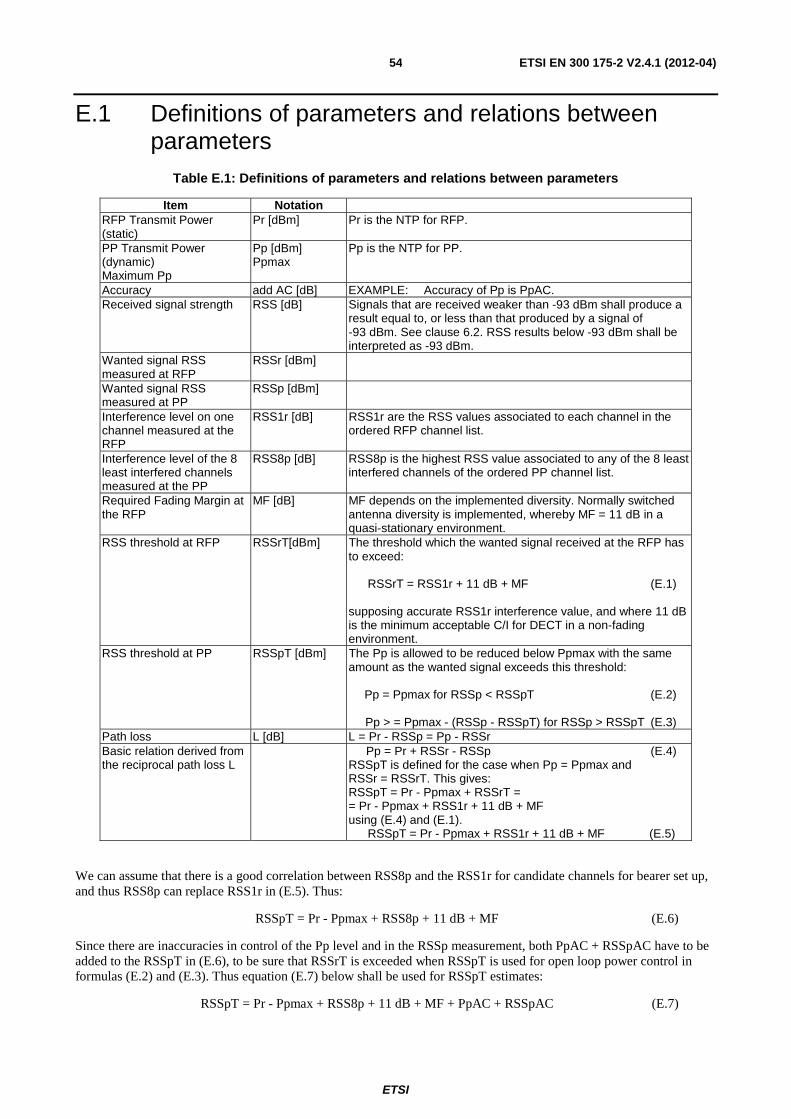
ETSI
ETSI EN 300 175-2 V2.4.1 (2012-04) 54
E.1 Definitions of parameters and relations between parameters
Table E.1: Definitions of parameters and relations between parameters
Item Notation RFP Transmit Power (static)
Pr [dBm] Pr is the NTP for RFP.
PP Transmit Power (dynamic) Maximum Pp
Pp [dBm] Ppmax
Pp is the NTP for PP.
Accuracy add AC [dB] EXAMPLE: Accuracy of Pp is PpAC. Received signal strength RSS [dB] Signals that are received weaker than -93 dBm shall produce a
result equal to, or less than that produced by a signal of -93 dBm. See clause 6.2. RSS results below -93 dBm shall be interpreted as -93 dBm.
Wanted signal RSS measured at RFP
RSSr [dBm]
Wanted signal RSS measured at PP
RSSp [dBm]
Interference level on one channel measured at the RFP
RSS1r [dB] RSS1r are the RSS values associated to each channel in the ordered RFP channel list.
Interference level of the 8 least interfered channels measured at the PP
RSS8p [dB] RSS8p is the highest RSS value associated to any of the 8 least interfered channels of the ordered PP channel list.
Required Fading Margin at the RFP
MF [dB] MF depends on the implemented diversity. Normally switched antenna diversity is implemented, whereby MF = 11 dB in a quasi-stationary environment.
RSS threshold at RFP RSSrT[dBm] The threshold which the wanted signal received at the RFP has to exceed: RSSrT = RSS1r + 11 dB + MF (E.1)
supposing accurate RSS1r interference value, and where 11 dB is the minimum acceptable C/I for DECT in a non-fading environment.
RSS threshold at PP RSSpT [dBm] The Pp is allowed to be reduced below Ppmax with the same amount as the wanted signal exceeds this threshold: Pp = Ppmax for RSSp < RSSpT (E.2)
Pp > = Ppmax - (RSSp - RSSpT) for RSSp > RSSpT (E.3)
Path loss L [dB] L = Pr - RSSp = Pp - RSSr Basic relation derived from the reciprocal path loss L
Pp = Pr + RSSr - RSSp (E.4) RSSpT is defined for the case when Pp = Ppmax and RSSr = RSSrT. This gives: RSSpT = Pr - Ppmax + RSSrT = = Pr - Ppmax + RSS1r + 11 dB + MF using (E.4) and (E.1). RSSpT = Pr - Ppmax + RSS1r + 11 dB + MF (E.5)
We can assume that there is a good correlation between RSS8p and the RSS1r for candidate channels for bearer set up, and thus RSS8p can replace RSS1r in (E.5). Thus:
RSSpT = Pr - Ppmax + RSS8p + 11 dB + MF (E.6)
Since there are inaccuracies in control of the Pp level and in the RSSp measurement, both PpAC + RSSpAC have to be added to the RSSpT in (E.6), to be sure that RSSrT is exceeded when RSSpT is used for open loop power control in formulas (E.2) and (E.3). Thus equation (E.7) below shall be used for RSSpT estimates:
RSSpT = Pr - Ppmax + RSS8p + 11 dB + MF + PpAC + RSSpAC (E.7)
ETSI
ETSI EN 300 175-2 V2.4.1 (2012-04) 55
E.2 Procedure for PP power adjustment due to movement
The control procedure allows decrease of power during a connection and also increase of power without first making intra-cell handover to a least interfered channel. But this increase shall be related to decrease of the PP received wanted signal strength, RSSp, whereby Pp has to be increased by a minimum amount while satisfying equations (E.2) and (E.3) in table E.1. Errors in received frames alone, without decrease in wanted signal level, are not allowed to trigger increased power, but should trigger an intracell handover.
The PP radio signal strength measure, RSSp, shall be a measure integrated over 10 frames to 30 frames (100 ms to 300 ms).
The PP shall have made a decision on the PP radio signal strength threshold, RSSpT, below which the PP power shall be reduced. See clause E.3. The PP Tx power Pp shall be set, and kept, as low as possible while satisfying equations (E.2) and (E.3) in table E.1:
Pp = Ppmax for RSSp < RSSpT
Pp ≥ Ppmax - (RSSp-RSSpT) for RSSp > RSSpT
The power control may be implemented with one single (large) power step, or with several smaller power steps. The smaller steps, the more optimized performance.
Intra-cell handover shall be made when the normal handover procedure is triggered by bit errors. Inter-cell handover shall be made with the normal procedures when another RFP becomes stronger.
E.3 Setting the power control threshold, RSSpT PP bearer set up is always made on a least interfered channel (EN 300 175-3 [3], clause 11.4) and the PP Tx power Pp shall be set according to equations (E.7a) and (E.7b).
The PP power control receive signal strength threshold, RSSpT, shall be set as:
RSSpT = Pr - Ppmax + RSS8p + 11 dB + MF + PpAC + RSSpAC dB (E.7a)
Where:
• Ppmax, PpAC and RSSpAC are known static parameters at the PP; and
• RSS8p is a known dynamic parameter at the PP.
Pr and MF may be known from received RFP broadcast information. See EN 300 175-3 [3], clause 7.2.4.3.10 for the "RFP power" broadcast PT information on Pr and MF.
If broadcast information is not available, the applied interoperability profile may specify maximum Pr and what kind of diversity is used.
If Pr is not known, it shall be set to 24 dBm. If MF is not known, it shall be set to 11 dB. These values are the default values.
Using the default values equation (E.7a) becomes:
RSSpT = 46 dB - Ppmax + RSS8p + PpAC + RSSpAC (E.7b)
A PP using broadcast information on Pr and MF has to use equation (E.7b) at bearer set up for inter-cell handover until proper broadcast information from the new RFP has been received, unless the earlier broadcast message includes information that all RFPs use the same Pr and MF values. See EN 300 175-3 [3], clause 7.2.4.3.10 for the "RFP power" broadcast PT information.

ETSI
ETSI EN 300 175-2 V2.4.1 (2012-04) 56
If the set up attempts for a call fail on 6 different bearers, the remaining set up attempts for this call may use full PP power on the same bearers. It is recommended that Ppmax is set equal to Pr if Pr is known, e.g. through the broadcast message of EN 300 175-3 [3], clause 7.2.4.3.10.
NOTE 1: Practical implementations may have a PpAC of 3 dB and an RSSpAC of about 6 dB. Thus for Ppmax = 24 dBm and RSS8p = -93 dBm RSSpT according to (E.7a) becomes -62 dBm.
NOTE 2: If a procedure to derive RSS8p is not available, it is possible to use either RSS1p for the bearer selected for set up or a fixed value, e.g. -83 dBm could be used for RSS8p. None of these two options are recommended.
NOTE 3: On-site modification the MF (and Pr) value in the EN 300 175-3 [3], clause 7.2.4.3.10 for the "RFP power" message can be used for on-site indirect fine tuning of the RSSpT.
ETSI
ETSI EN 300 175-2 V2.4.1 (2012-04) 57
Annex F (normative): DECT carrier numbers and carrier positions in the range 1 880 MHz to 2 025 MHz and for the US market 902 MHz to 928 MHz and 2 400 MHz to 2 483,5 MHz
F.1 Introduction DECT carriers are specified for the whole frequency range 1 880 MHz to 2 025 MHz and for the US market for the ISM bands 902 MHz to 928 MHz and 2 400 MHz to 2 483,5 MHz [12].
RF carriers for IMT-FT [10] applications of DECT are placed within the parts of the European UMTS spectrum applicable for TDD operation (see ECC/DEC/(06)01 [13], e.g. within 1 900 MHz to 1 920 MHz, 1 920 MHz to 1 980 MHz and/or 2 010 MHz to 2 025 MHz).
The most common spectrum allocation is 1 880 MHz to 1 900 MHz, but outside Europe spectrum is also available in 1 900 MHz to 1 920 MHz and in 1 910 MHz to 1 930 MHz (several countries).
An RF carrier is defined by its centre frequency Fc.
The DECT fixed part (base stations of the same system) broadcast messages indicate the locally relevant carriers to ensure that PPs and CTAs set up calls only within the locally allocated band. These broadcast messages from a specific local fixed part contain information on the carrier frequencies of up to 64 carrier positions Fc, and whether each of these is allowed to be used or not. The frequencies for carrier numbers c = 0, 1, … 9 are fixed for the band 1 880 MHz to 1 900 MHz, but the frequencies for carriers c = 10, 11, …, 63 depend on the specific RF band number (see EN 300 175-3 [3], clauses 7.2.3.2.8, 7.2.3.3 and 7.2.3.9).
NOTE: RF band number 00111 is not used. It was earlier defined for a Technical Specification that became obsolete.
The carrier numbers c = 0, 1, 2, ..., 9 are for the frequency band 1 880 MHz to 1 900 MHz. Those 10 RF-carrier centre frequencies Fc are given by:
Fc = F0 - c × 1,728 MHz
Where:
F0 = 1 897,344 MHz.
For extension of carrier positions to cover bands from 1 900 MHz up to 2 025 MHz, a basic set of partially overlapping RF bands have been defined in clauses F.3 to F.6 by using only the Extended RF carrier information part 1 message (see EN 300 175-3 [3], clause 7.2.3.3). Clause F.2 uses in addition the Extended RF carrier information part 2 message, whereby the total number of useful carriers for a system is increased from 33 to 64 carriers (see EN 300 175-3 [3], clause 7.2.3.9). New or modified carrier positions and/or bands can (locally) be defined when needed.
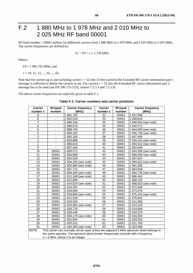
ETSI
ETSI EN 300 175-2 V2.4.1 (2012-04) 58
F.2 1 880 MHz to 1 978 MHz and 2 010 MHz to 2 025 MHz RF band 00001
RF-band number = 00001 defines 54 additional carriers from 1 880 MHz to 1 979 MHz and 2 010 MHz to 2 025 MHz. The carrier frequencies are defined by:
Fc = F9 + c × 1,728 MHz
Where:
F9 = 1 881,792 MHz; and
c = 10, 11, 12, ..., 32, ..., 63.
Note that for carriers up to and including carrier c = 32 (the 33 first carriers) the Extended RF carrier information part 1 message is sufficient to define the carriers in use. For carriers c > 32 also the Extended RF carrier information part 2 message has to be used (see EN 300 175-3 [3], clauses 7.2.3.3 and 7.2.3.9).
The above carrier frequencies are explicitly given in table F.1.
Table F.1: Carrier numbers and carrier positions
Carrier number c
Rf-band number
Carrier frequency (MHz)
Carrier number c
Rf-band number
Carrier frequency (MHz)
9 - 1 881,792 32 00001 1 937,088 8 - 1 883,520 33 00001 1 938,816 7 - 1 885,248 34 00001 1 940,544 (see note) 6 - 1 886,876 35 00001 1 942,272 5 - 1 888,704 36 00001 1 944,000 (see note) 4 - 1 890,432 37 00001 1 945,728 (see note) 3 - 1 892,160 38 00001 1 947,456 2 - 1 893,888 39 00001 1 949,184 (see note) 1 - 1 895,616 40 00001 1 950,912 (see note) 0 - 1 897,344 41 00001 1 952,640 10 00001 1 899,072 42 00001 1 954,368 (see note) 11 00001 1 900,800 43 00001 1 956,096 (see note) 12 00001 1 902,528 44 00001 1 957,824 13 00001 1 904,256 (see note) 45 00001 1 959,552 (see note) 14 00001 1 905,984 (see note) 46 00001 1 961,280 15 00001 1 907,712 47 00001 1 963,008 16 00001 1 909,440 (see note) 48 00001 1 964,736 (see note) 17 00001 1 911,168 (see note) 49 00001 1 966,464 18 00001 1 912,896 50 00001 1 968,192 19 00001 1 914,624 (see note) 51 00001 1 969,920 (see note) 20 00001 1 916,352 52 00001 1 971,648 21 00001 1 918,080 53 00001 1 973,376 22 00001 1 919,808 (see note) 54 00001 1 975,104 (see note) 23 00001 1 921,536 55 00001 1 976,832 24 00001 1 923,264 56 00001 2 011,392 25 00001 1 924,992 (see note) 57 00001 2 013,120 26 00001 1 926,720 58 00001 2 014,848 27 00001 1 928,448 59 00001 2 016,576 28 00001 1 930,176 (see note) 60 00001 2 018,304 29 00001 1 931,904 61 00001 2 020,032 30 00001 1 933,632 62 00001 2 021,760 31 00001 1 935,360 (see note) 63 00001 2 023,488
NOTE: This carrier can normally not be used unless the adjacent 5 MHz spectrum block belongs to the same operator. The spectrum block border frequencies coincide with a frequency n × 5 MHz, where n is an integer.
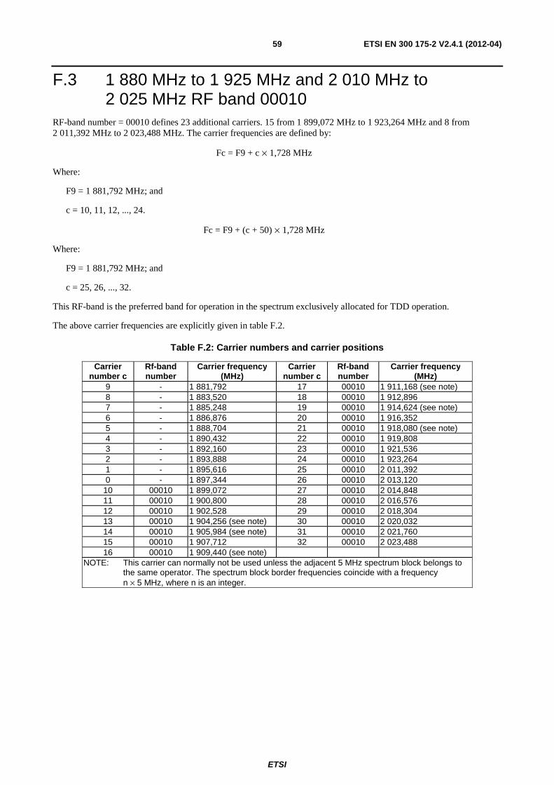
ETSI
ETSI EN 300 175-2 V2.4.1 (2012-04) 59
F.3 1 880 MHz to 1 925 MHz and 2 010 MHz to 2 025 MHz RF band 00010
RF-band number = 00010 defines 23 additional carriers. 15 from 1 899,072 MHz to 1 923,264 MHz and 8 from 2 011,392 MHz to 2 023,488 MHz. The carrier frequencies are defined by:
Fc = F9 + c × 1,728 MHz
Where:
F9 = 1 881,792 MHz; and
c = 10, 11, 12, ..., 24.
Fc = F9 + (c + 50) × 1,728 MHz
Where:
F9 = 1 881,792 MHz; and
c = 25, 26, ..., 32.
This RF-band is the preferred band for operation in the spectrum exclusively allocated for TDD operation.
The above carrier frequencies are explicitly given in table F.2.
Table F.2: Carrier numbers and carrier positions
Carrier number c
Rf-band number
Carrier frequency (MHz)
Carrier number c
Rf-band number
Carrier frequency (MHz)
9 - 1 881,792 17 00010 1 911,168 (see note) 8 - 1 883,520 18 00010 1 912,896 7 - 1 885,248 19 00010 1 914,624 (see note) 6 - 1 886,876 20 00010 1 916,352 5 - 1 888,704 21 00010 1 918,080 (see note) 4 - 1 890,432 22 00010 1 919,808 3 - 1 892,160 23 00010 1 921,536 2 - 1 893,888 24 00010 1 923,264 1 - 1 895,616 25 00010 2 011,392 0 - 1 897,344 26 00010 2 013,120
10 00010 1 899,072 27 00010 2 014,848 11 00010 1 900,800 28 00010 2 016,576 12 00010 1 902,528 29 00010 2 018,304 13 00010 1 904,256 (see note) 30 00010 2 020,032 14 00010 1 905,984 (see note) 31 00010 2 021,760 15 00010 1 907,712 32 00010 2 023,488 16 00010 1 909,440 (see note)
NOTE: This carrier can normally not be used unless the adjacent 5 MHz spectrum block belongs to the same operator. The spectrum block border frequencies coincide with a frequency n × 5 MHz, where n is an integer.
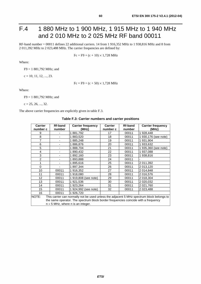
ETSI
ETSI EN 300 175-2 V2.4.1 (2012-04) 60
F.4 1 880 MHz to 1 900 MHz, 1 915 MHz to 1 940 MHz and 2 010 MHz to 2 025 MHz RF band 00011
RF-band number = 00011 defines 22 additional carriers. 14 from 1 916,352 MHz to 1 938,816 MHz and 8 from 2 011,392 MHz to 2 023,488 MHz. The carrier frequencies are defined by:
Fc = F9 + (c + 10) × 1,728 MHz
Where:
F9 = 1 881,792 MHz; and
c = 10, 11, 12, ..., 23.
Fc = F9 + (c + 50) × 1,728 MHz
Where:
F9 = 1 881,792 MHz; and
c = 25, 26, ..., 32.
The above carrier frequencies are explicitly given in table F.3.
Table F.3: Carrier numbers and carrier positions
Carrier number c
Rf-band number
Carrier frequency (MHz)
Carrier number c
Rf-band number
Carrier frequency (MHz)
9 - 1 881,792 17 00011 1 928,448 8 - 1 883,520 18 00011 1 930,176 (see note) 7 - 1 885,248 19 00011 1 931,904 6 - 1 886,876 20 00011 1 933,632 5 - 1 888,704 21 00011 1 935,360 (see note) 4 - 1 890,432 22 00011 1 937,088 3 - 1 892,160 23 00011 1 938,816 2 - 1 893,888 24 00011 - 1 - 1 895,616 25 00011 2 011,392 0 - 1 897,344 26 00011 2 013,120
10 00011 1 916,352 27 00011 2 014,848 11 00011 1 918,080 28 00011 2 016,576 12 00011 1 919,808 (see note) 29 00011 2 018,304 13 00011 1 921,536 30 00011 2 020,032 14 00011 1 923,264 31 00011 2 021,760 15 00011 1 924,992 (see note) 32 00011 2 023,488 16 00011 1 926,720
NOTE: This carrier can normally not be used unless the adjacent 5 MHz spectrum block belongs to the same operator. The spectrum block border frequencies coincide with a frequency n × 5 MHz, where n is an integer.

ETSI
ETSI EN 300 175-2 V2.4.1 (2012-04) 61
F.5 1 880 MHz to 1 900 MHz, 1 935 MHz to 1 960 MHz and 2 010 MHz to 2 025 MHz RF band 00100
RF-band number = 00100 defines 22 additional carriers. 14 from 1 937,088 MHz to 1 959,489 MHz and 8 from 2 011,392 MHz to 2 023,488 MHz. The carrier frequencies are defined by:
Fc = F9 + (c + 22) × 1,728 MHz
Where:
F9 = 1 881,792 MHz; and
c = 10, 11, 12, ..., 23.
Fc = F9 + (c + 50) × 1,728 MHz
Where:
F9 = 1 881,792 MHz; and
c = 25, 26, ..., 32.
The above carrier frequencies are explicitly given in table F.4.
Table F.4: Carrier numbers and carrier positions
Carrier number c
Rf-band number
Carrier frequency (MHz)
Carrier number c
Rf-band number
Carrier frequency (MHz)
9 - 1 881,792 17 00100 1 949,184 (see note) 8 - 1 883,520 18 00100 1 950,912 (see note) 7 - 1 885,248 19 00100 1 952,640 6 - 1 886,876 20 00100 1 954,368 (see note) 5 - 1 888,704 21 00100 1 956,096 (see note) 4 - 1 890,432 22 00100 1 957,824 3 - 1 892,160 23 00100 - 2 - 1 893,888 24 00100 - 1 - 1 895,616 25 00100 2 011,392 0 - 1 897,344 26 00100 2 013,120
10 00100 1 937,088 27 00100 2 014,848 11 00100 1 938,816 28 00100 2 016,576 12 00100 1 940,544 (see note) 29 00100 2 018,304 13 00100 1 942,272 30 00100 2 020,032 14 00100 1 944,000 (see note) 31 00100 2 021,760 15 00100 1 945,728 (see note) 32 00100 2 023,488 16 00100 1 947,456
NOTE: This carrier can normally not be used unless the adjacent 5 MHz spectrum block belongs to the same operator. The spectrum block border frequencies coincide with a frequency n × 5 MHz, where n is an integer.
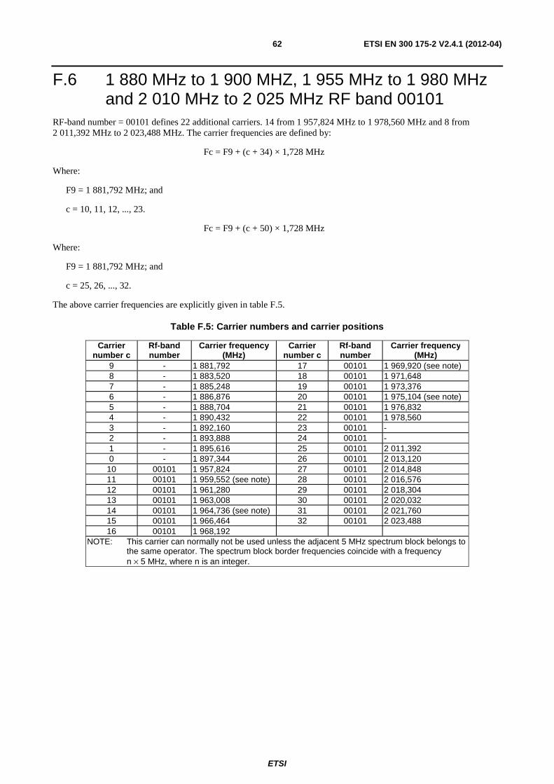
ETSI
ETSI EN 300 175-2 V2.4.1 (2012-04) 62
F.6 1 880 MHz to 1 900 MHZ, 1 955 MHz to 1 980 MHz and 2 010 MHz to 2 025 MHz RF band 00101
RF-band number = 00101 defines 22 additional carriers. 14 from 1 957,824 MHz to 1 978,560 MHz and 8 from 2 011,392 MHz to 2 023,488 MHz. The carrier frequencies are defined by:
Fc = F9 + (c + 34) × 1,728 MHz
Where:
F9 = 1 881,792 MHz; and
c = 10, 11, 12, ..., 23.
Fc = F9 + (c + 50) × 1,728 MHz
Where:
F9 = 1 881,792 MHz; and
c = 25, 26, ..., 32.
The above carrier frequencies are explicitly given in table F.5.
Table F.5: Carrier numbers and carrier positions
Carrier number c
Rf-band number
Carrier frequency (MHz)
Carrier number c
Rf-band number
Carrier frequency (MHz)
9 - 1 881,792 17 00101 1 969,920 (see note) 8 - 1 883,520 18 00101 1 971,648 7 - 1 885,248 19 00101 1 973,376 6 - 1 886,876 20 00101 1 975,104 (see note) 5 - 1 888,704 21 00101 1 976,832 4 - 1 890,432 22 00101 1 978,560 3 - 1 892,160 23 00101 - 2 - 1 893,888 24 00101 - 1 - 1 895,616 25 00101 2 011,392 0 - 1 897,344 26 00101 2 013,120
10 00101 1 957,824 27 00101 2 014,848 11 00101 1 959,552 (see note) 28 00101 2 016,576 12 00101 1 961,280 29 00101 2 018,304 13 00101 1 963,008 30 00101 2 020,032 14 00101 1 964,736 (see note) 31 00101 2 021,760 15 00101 1 966,464 32 00101 2 023,488 16 00101 1 968,192
NOTE: This carrier can normally not be used unless the adjacent 5 MHz spectrum block belongs to the same operator. The spectrum block border frequencies coincide with a frequency n × 5 MHz, where n is an integer.
ETSI
ETSI EN 300 175-2 V2.4.1 (2012-04) 63
F.7 US ISM band carriers Standard DECT can since May 2002 be applied in the US within the ISM bands 902 MHz to 928 MHz, 2 400 MHz to 2 483,5 MHz and 5 725 MHz to 5 850 MHz [12].
NOTE 1: There is no protected spectrum for standard DECT available in the US. Opposite to a protected DECT spectrum allowing for uncoordinated DECT installations, the ISM bands allows for uncoordinated usage of a variety of incompatible communication devices and also industrial, scientific and medical devices. Therefore maintenance of high quality of service will not be guaranteed when other types of ISM devices (non-DECT devices) are used in the same local area. This applies especially to voice and video services, but is less critical for best effort packet data services, where non-time-critical retransmissions are applied. The band 902 MHz to 928 MHz could be preferred over the 2 400 MHz to 2 483,5 MHz band due to the lack of potential interference from IEEE 802.11b/g [i.8] WLANs, microwave ovens and Bluetooth devices. The 900 MHz spectrum provides better range than the 2,4 GHz spectrum.
NOTE 2: In the US, DECT can also operate in the band 1 920 MHz to 1 930 MHz, that is reserved for the operation of "Isochronous Unlicensed Personal Communication Service Devices".
Below DECT carrier frequencies are defined for the US ISM bands 902 MHz to 928 MHz and 2 400 MHz to 2 483,5 MHz. Carrier notations for the 5 GHz band could be added upon demand.
F.7.1 902 MHz to 928 MHz RF band 01000 RF-band number = 01000 defines 14 additional carriers from 903,744 MHz to 926,208 MHz. The carrier frequencies are defined by:
Fc = 903,744 MHz + (c - 10) × 1,728 MHz
Where:
c = 10, 11, 12, ..., 23.
F.7.2 2 400 MHz to 2 483,5 MHz RF band 01001 RF-band number = 01001 defines 45 additional carriers from 2 403,648 MHz to 2 479,680 MHz. The carrier frequencies are defined by:
Fc = 2 403,648 MHz + (c - 10) × 1,728 MHz
Where:
c = 10, 11, 12, ..., 54.
Note that for this RF band number 01001, there are 45 additional carrier positions. Thus also the Extended RF carrier information part 2 message has to be used (see EN 300 175-3 [3], clause 7.2.3.9). This message extends the number of useful carriers for a system from 33 to 64 carriers.
ETSI
ETSI EN 300 175-2 V2.4.1 (2012-04) 64
Annex G (informative): Bibliography
• ETSI TR 101 310: "Digital Enhanced Cordless Telecommunications (DECT); Traffic Capacity and Spectrum Requirements for Multi-System and Multi-Service DECT Applications Co-existing in a Common Frequency Band".
• ETSI EN 300 175-7: "Digital Enhanced Cordless Telecommunications (DECT); Common Interface (CI); Part 7: Security features".
• ETSI EN 300 175-8: "Digital Enhanced Cordless Telecommunications (DECT); Common Interface (CI); Part 8: Speech and audio coding and transmission".
• CENELEC ENV 50166-2: "Human Exposure to Electromagnetic Fields High Frequency: (10 kHz to 300 GHz)", European Prestandard, European Committee for Electrotechnical Standardization (CENELEC), January 1995.
• IEEE 802.11g: "IEEE Standard for Information Technology - Telecommunications and Information Exchange Between Systems - Local and Metropolitan Area Networks - Specific Requirements - Part 11: Wireless LAN Medium Access Control (MAC) and Physical Layer (PHY) Specifications: Further Higher Data Rate Extension in the 2.4 GHz Band".
• IEEE 802.15.1: "IEEE Standard for Information Technology - telecommunications and information exchange Systems between systems - Local and metropolitan area networks-Specific requirements - Part 15.1a: Wireless Medium Access Control (MAC) and Physical Layer (PHY) specifications for Wireless Personal Area Networks (WPAN)".
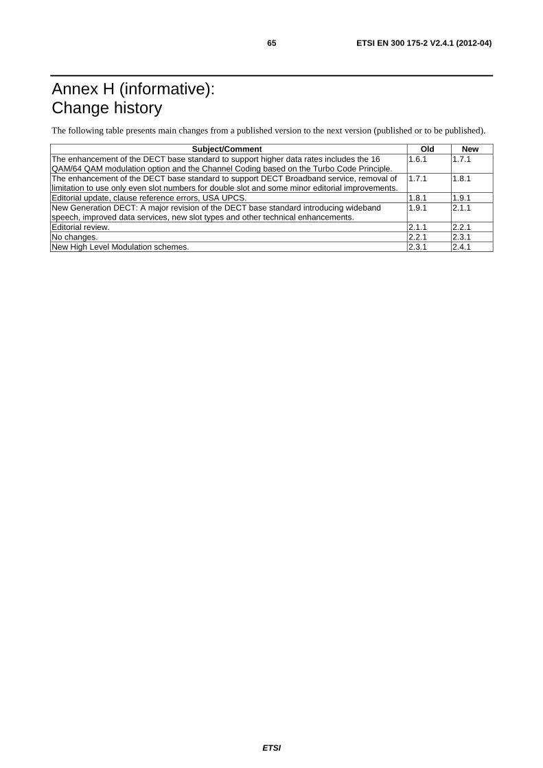
ETSI
ETSI EN 300 175-2 V2.4.1 (2012-04) 65
Annex H (informative): Change history The following table presents main changes from a published version to the next version (published or to be published).
Subject/Comment Old New The enhancement of the DECT base standard to support higher data rates includes the 16 QAM/64 QAM modulation option and the Channel Coding based on the Turbo Code Principle.
1.6.1 1.7.1
The enhancement of the DECT base standard to support DECT Broadband service, removal of limitation to use only even slot numbers for double slot and some minor editorial improvements.
1.7.1 1.8.1
Editorial update, clause reference errors, USA UPCS. 1.8.1 1.9.1 New Generation DECT: A major revision of the DECT base standard introducing wideband speech, improved data services, new slot types and other technical enhancements.
1.9.1 2.1.1
Editorial review. 2.1.1 2.2.1 No changes. 2.2.1 2.3.1 New High Level Modulation schemes. 2.3.1 2.4.1

ETSI
ETSI EN 300 175-2 V2.4.1 (2012-04) 66
History
Document history
Edition 1 October 1992 Publication as ETS 300 175-2 (Historical)
Edition 2 September 1996 Publication as ETS 300 175-2 (Historical)
V1.4.2 June 1999 Publication
V1.5.1 February 2001 Publication
V1.6.1 August 2001 Publication
V1.7.1 July 2003 Publication
V1.8.1 November 2004 Publication
V1.9.1 September 2005 Publication
V2.1.1 August 2007 Publication
V2.2.1 November 2008 Publication
V2.3.1 June 2010 Publication
V2.4.0 December 2011 One-step Approval Procedure OAP 20120417: 2012-12-19 to 2012-04-17
V2.4.1 April 2012 Publication


