169
ETSI EN 300 175-4 V2.4.1 (2012-04) Digital Enhanced Cordless Telecommunications (DECT); Common Interface (CI); Part 4: Data Link Control (DLC) layer European Standard
| Date post: | 12-Sep-2018 |
| Category: |
Documents |
| Upload: | hoangtuyen |
| View: | 227 times |
| Download: | 1 times |
ETSI EN 300 175-4 V2.4.1 (2012-04)
Digital Enhanced Cordless Telecommunications (DECT); Common Interface (CI);
Part 4: Data Link Control (DLC) layer
European Standard
ETSI
ETSI EN 300 175-4 V2.4.1 (2012-04) 2
Reference REN/DECT-000260
Keywords DECT, IMT-2000, mobility, radio, TDD, TDMA
ETSI
650 Route des Lucioles F-06921 Sophia Antipolis Cedex - FRANCE
Tel.: +33 4 92 94 42 00 Fax: +33 4 93 65 47 16
Siret N° 348 623 562 00017 - NAF 742 C
Association à but non lucratif enregistrée à la Sous-Préfecture de Grasse (06) N° 7803/88
Important notice
Individual copies of the present document can be downloaded from: http://www.etsi.org
The present document may be made available in more than one electronic version or in print. In any case of existing or perceived difference in contents between such versions, the reference version is the Portable Document Format (PDF).
In case of dispute, the reference shall be the printing on ETSI printers of the PDF version kept on a specific network drive within ETSI Secretariat.
Users of the present document should be aware that the document may be subject to revision or change of status. Information on the current status of this and other ETSI documents is available at
http://portal.etsi.org/tb/status/status.asp
If you find errors in the present document, please send your comment to one of the following services: http://portal.etsi.org/chaircor/ETSI_support.asp
Copyright Notification
No part may be reproduced except as authorized by written permission. The copyright and the foregoing restriction extend to reproduction in all media.
© European Telecommunications Standards Institute 2012.
All rights reserved.
DECTTM, PLUGTESTSTM, UMTSTM and the ETSI logo are Trade Marks of ETSI registered for the benefit of its Members. 3GPPTM and LTE™ are Trade Marks of ETSI registered for the benefit of its Members and
of the 3GPP Organizational Partners. GSM® and the GSM logo are Trade Marks registered and owned by the GSM Association.
ETSI
ETSI EN 300 175-4 V2.4.1 (2012-04) 3
Contents
Intellectual Property Rights .............................................................................................................................. 11
Foreword ........................................................................................................................................................... 11
1 Scope ...................................................................................................................................................... 12
2 References .............................................................................................................................................. 13
2.1 Normative references ....................................................................................................................................... 13
2.2 Informative references ...................................................................................................................................... 14
3 Definitions, symbols and abbreviations ................................................................................................. 14
3.1 Definitions ........................................................................................................................................................ 14
3.2 Symbols and abbreviations ............................................................................................................................... 14
4 Data Link Control (DLC) layer overview .............................................................................................. 16
4.1 General ............................................................................................................................................................. 16
4.2 C-plane services ............................................................................................................................................... 17
4.3 U-plane services ............................................................................................................................................... 18
4.4 Lower Layer Management Entity (LLME) ...................................................................................................... 21
5 C-plane service characteristics ............................................................................................................... 21
5.1 Data link service (LAPC+Lc) ........................................................................................................................... 21
5.1.1 General ........................................................................................................................................................ 21
5.1.2 LAPC types of operation ............................................................................................................................ 22
5.1.3 Establishment of information transfer modes ............................................................................................. 22
5.1.3.1 Data Link Identifier (DLI) .................................................................................................................... 22
5.1.3.2 LAPC states........................................................................................................................................... 22
5.2 Broadcast service (Lb) ...................................................................................................................................... 23
6 Frame structures for C-plane services .................................................................................................... 24
6.1 Data link service frame structure ...................................................................................................................... 24
6.1.1 General frame structure .............................................................................................................................. 24
6.1.2 Lc frame delimiting and transparency ........................................................................................................ 25
6.1.3 Transmission order ..................................................................................................................................... 25
6.1.4 Routing to logical channels ......................................................................................................................... 25
6.1.4.1 CF/CLF logical channel .......................................................................................................................... 25
6.1.4.2 CS/CLS logical channel .......................................................................................................................... 26
6.1.5 Invalid frames ............................................................................................................................................. 26
6.2 Broadcast service frame structure..................................................................................................................... 27
6.2.1 Standard frame structure ............................................................................................................................. 27
6.2.2 Extended frame structure ............................................................................................................................ 27
7 Elements of procedures and formats of fields for C-plane peer-to-peer communication ....................... 28
7.1 General ............................................................................................................................................................. 28
7.2 Address field formats ....................................................................................................................................... 28
7.3 Address field parameters .................................................................................................................................. 28
7.3.1 REServed bit (RES) .................................................................................................................................... 28
7.3.2 Command Response (C/R) bit .................................................................................................................... 28
7.3.3 SAPI field ................................................................................................................................................... 28
7.3.4 New Link Flag (NLF) bit ............................................................................................................................ 29
7.3.5 LLN-field .................................................................................................................................................... 29
7.3.6 Data Link Identifiers (DLI) ......................................................................................................................... 29
7.4 Control field formats ........................................................................................................................................ 30
7.5 Control field parameters ................................................................................................................................... 30
7.5.1 Poll/Final (P/F) bit ...................................................................................................................................... 30
7.5.2 Multiple frame operation variables and sequence numbers ........................................................................ 30
7.5.2.1 Modulus ................................................................................................................................................ 30
7.5.2.2 Send state Variable V(S) ....................................................................................................................... 30
7.5.2.3 Acknowledge state Variable V(A) ........................................................................................................ 31
7.5.2.4 Send sequence Number N(S) ................................................................................................................ 31
ETSI
ETSI EN 300 175-4 V2.4.1 (2012-04) 4
7.5.2.5 Receive state Variable V(R) .................................................................................................................. 31
7.5.2.6 Receive sequence Number N(R) ........................................................................................................... 31
7.5.3 Unacknowledged operation variables and sequence numbers .................................................................... 31
7.5.4 Supervisory and Unnumbered function bits S and U .................................................................................. 31
7.6 Length indicator field format............................................................................................................................ 31
7.7 Length indicator field parameters ..................................................................................................................... 32
7.7.1 Length indicator field extension bit (N) ...................................................................................................... 32
7.7.2 More data bit (M) ........................................................................................................................................ 32
7.7.3 Length parameter (LI) ................................................................................................................................. 32
7.7.4 Extended length parameter (LJJ) ................................................................................................................. 33
7.7.5 Reserved bit (RES) ..................................................................................................................................... 33
7.8 Fill field format ................................................................................................................................................ 33
7.9 Checksum field format ..................................................................................................................................... 33
7.10 Checksum field parameters .............................................................................................................................. 33
7.11 Commands and responses ................................................................................................................................ 35
7.11.1 Information (I) command ............................................................................................................................ 35
7.11.2 Receive Ready (RR) command/response .................................................................................................... 35
7.11.3 Receive Not Ready (RNR) command/response .......................................................................................... 36
7.11.4 REJect (REJ) command/response ............................................................................................................... 36
7.11.5 Set Asynchronous Balanced Mode (SABM) command .............................................................................. 36
7.11.6 Disconnect Mode (DM) response ............................................................................................................... 36
7.11.7 Unnumbered Information (UI) command ................................................................................................... 36
7.11.8 DISConnect (DISC) command ................................................................................................................... 37
7.11.9 Unnumbered ACK (UA) response .............................................................................................................. 37
8 Primitives ............................................................................................................................................... 37
8.1 Primitive types .................................................................................................................................................. 37
8.2 Primitives to the MAC layer (lower layer) ....................................................................................................... 37
8.3 Primitives to the NWK layer (higher layer) ..................................................................................................... 37
8.3.1 Parameter definitions .................................................................................................................................. 38
8.3.2 S-SAP primitives ........................................................................................................................................ 39
8.3.2.1 DL_ESTABLISH primitive .................................................................................................................. 39
8.3.2.2 DL_RELEASE primitive ...................................................................................................................... 39
8.3.2.3 DL_DATA primitive ............................................................................................................................. 40
8.3.2.4 DL_UNIT_DATA primitive ................................................................................................................. 40
8.3.2.5 DL_SUSPEND primitive ...................................................................................................................... 40
8.3.2.6 DL_RESUME primitive ........................................................................................................................ 40
8.3.2.7 DL_ENC_KEY primitive ...................................................................................................................... 41
8.3.2.8 DL_ENCRYPT primitive ...................................................................................................................... 41
8.3.2.9 DL_SERVICE_MOD primitive ............................................................................................................ 41
8.3.3 B-SAP primitives ........................................................................................................................................ 41
8.3.3.1 DL_BROADCAST primitive ................................................................................................................ 42
8.3.3.2 DL_EXPEDITED primitive .................................................................................................................. 42
8.4 Primitives to the interworking unit ................................................................................................................... 42
8.4.1 Parameter definitions .................................................................................................................................. 42
8.4.2 LUX-SAP primitives ................................................................................................................................... 43
8.4.2.1 DL_U_DATA primitive ........................................................................................................................ 43
8.4.2.2 DL_U_UNIT_DATA primitive ............................................................................................................ 43
8.4.2.3 DL_U_ERROR primitive ...................................................................................................................... 43
9 C-plane peer-to-peer procedures ............................................................................................................ 44
9.1 General ............................................................................................................................................................. 44
9.2 Point to point acknowledged operation ............................................................................................................ 44
9.2.1 Procedure for the use of the P/F bit ............................................................................................................ 44
9.2.1.1 Class A acknowledged information transfer ......................................................................................... 44
9.2.1.2 Class B acknowledged information transfer ......................................................................................... 45
9.2.2 Use of LLN ................................................................................................................................................. 45
9.2.2.1 Class A operation .................................................................................................................................. 45
9.2.2.2 Class B operation .................................................................................................................................. 45
9.2.3 Link establishment and information transfer in class A operation .............................................................. 45
9.2.3.1 Establishing class A operation .............................................................................................................. 45
9.2.3.2 Class A acknowledged information transfer ......................................................................................... 46
ETSI
ETSI EN 300 175-4 V2.4.1 (2012-04) 5
9.2.3.3 Transmission of class A I-frames .......................................................................................................... 46
9.2.3.4 Reception of class A I-frames ............................................................................................................... 47
9.2.3.5 Receiving acknowledgements ............................................................................................................... 47
9.2.3.6 Waiting for acknowledgement .............................................................................................................. 47
9.2.3.7 Release of class A operation ................................................................................................................. 48
9.2.3.8 Re-establishment of class A operation .................................................................................................. 48
9.2.4 Establishing class B multiple frame operation ............................................................................................ 48
9.2.4.1 Overview ............................................................................................................................................... 48
9.2.4.2 Class B multiple frame establishment procedures ................................................................................. 49
9.2.4.3 Class B LLN assignment procedures .................................................................................................... 50
9.2.4.3.1 PT establishment ............................................................................................................................. 50
9.2.4.3.2 FT establishment ............................................................................................................................. 51
9.2.5 Link maintenance and information transfer in class B multiple frame operation ....................................... 51
9.2.5.1 Transmitting I-frames............................................................................................................................ 51
9.2.5.2 Receiving I-frames ................................................................................................................................ 52
9.2.5.2.1 P bit set to 1 ..................................................................................................................................... 52
9.2.5.2.2 P bit set to 0 ..................................................................................................................................... 52
9.2.5.3 Sending and receiving acknowledgements ............................................................................................ 52
9.2.5.3.1 Sending acknowledgements ............................................................................................................ 52
9.2.5.3.2 Receiving acknowledgements ......................................................................................................... 52
9.2.5.4 Receiving REJ-frames ........................................................................................................................... 53
9.2.5.5 Receiving RNR-frames ......................................................................................................................... 54
9.2.5.6 LAPC own receiver busy condition ...................................................................................................... 55
9.2.5.7 Waiting acknowledgement .................................................................................................................... 55
9.2.5.8 Appropriate supervisory frame.............................................................................................................. 56
9.2.6 Release of class B multiple frame operation ............................................................................................... 56
9.2.7 Link suspension and resumption ................................................................................................................. 57
9.2.7.1 Link suspension ..................................................................................................................................... 57
9.2.7.1.1 Class B acknowledged suspend ....................................................................................................... 57
9.2.7.1.2 Unacknowledged suspend ............................................................................................................... 58
9.2.7.2 Class B link resumption ........................................................................................................................ 59
9.2.7.3 Connection handover ............................................................................................................................ 60
9.2.7.3.1 Class A connection handover .......................................................................................................... 61
9.2.7.3.2 Class B connection handover .......................................................................................................... 62
9.2.7.3.3 Expiry of connection handover timer .............................................................................................. 62
9.2.8 Re-establishment of class B multi-frame operation .................................................................................... 62
9.2.8.1 Criteria for re-establishment.................................................................................................................. 62
9.2.8.2 Procedure .............................................................................................................................................. 63
9.2.9 Exception handling ..................................................................................................................................... 63
9.2.9.1 General .................................................................................................................................................. 63
9.2.9.2 Class B exception condition reporting and recovery ............................................................................. 64
9.2.9.2.1 N(S) sequence error ......................................................................................................................... 64
9.2.9.2.2 N(R) sequence error ........................................................................................................................ 64
9.2.9.2.3 Timer recovery condition ................................................................................................................ 64
9.2.9.2.4 Collision of identical transmitted and received commands ............................................................. 64
9.3 Unacknowledged operation .............................................................................................................................. 65
9.3.1 Use of LLN for unacknowledged information transfer ............................................................................... 65
9.3.2 Class U link establishment .......................................................................................................................... 65
9.3.3 Unacknowledged information transfer ........................................................................................................ 65
9.3.3.1 Transmission of unacknowledged information ..................................................................................... 65
9.3.3.2 Reception of unacknowledged information .......................................................................................... 65
9.3.4 Unacknowledged release ............................................................................................................................ 65
9.4 Broadcast operation .......................................................................................................................................... 65
9.4.1 Normal operation ........................................................................................................................................ 65
9.4.1.1 Procedure in the Fixed radio Termination (FT) .................................................................................... 65
9.4.1.2 Procedure in the Portable radio Termination (PT) ................................................................................ 66
9.4.2 Expedited operation .................................................................................................................................... 66
9.4.2.1 Procedure in the Fixed radio Termination (FT) .................................................................................... 66
9.4.2.2 Procedure in the Portable radio Termination (PT) ................................................................................ 66
9.5 MAC layer interfaces ....................................................................................................................................... 67
9.5.1 MC-SAP ..................................................................................................................................................... 67
9.5.1.1 C-plane overview .................................................................................................................................. 67
ETSI
ETSI EN 300 175-4 V2.4.1 (2012-04) 6
9.5.1.2 C-plane service data procedures ............................................................................................................ 67
9.5.1.3 U-plane service data .............................................................................................................................. 68
9.5.2 MB-SAP ..................................................................................................................................................... 68
9.5.2.1 C-plane service data procedures ............................................................................................................ 68
9.5.2.2 U-plane service data .............................................................................................................................. 68
9.5.3 MA-SAP ..................................................................................................................................................... 69
9.5.3.1 Overview ............................................................................................................................................... 69
9.5.3.2 Service data procedures ......................................................................................................................... 69
10 Management procedures......................................................................................................................... 69
10.1 Lower Layer Management Entity (LLME) ...................................................................................................... 69
10.2 MAC connection management ......................................................................................................................... 70
10.2.1 MAC connection set-up .............................................................................................................................. 70
10.2.2 MAC connection release ............................................................................................................................. 70
10.2.3 MAC connection modification ................................................................................................................... 70
10.2.4 MAC connection identifiers ........................................................................................................................ 71
10.2.4.1 Overview ............................................................................................................................................... 71
10.2.4.2 Advanced MAC Connection Identifiers (AMCI) .................................................................................. 71
10.2.4.3 Basic MAC Connection Identifiers (BMCI) ......................................................................................... 72
10.2.4.4 MAC Connection Endpoint Identifier (MCEI) ..................................................................................... 72
10.2.5 Selection of logical channel (CS or CF) ....................................................................................................... 72
10.3 DLC C-plane (LAPC) management ................................................................................................................. 73
10.3.1 Provision of link signature .......................................................................................................................... 73
10.3.2 Routing of connection oriented links .......................................................................................................... 73
10.3.3 Routing of connectionless links .................................................................................................................. 74
10.4 DLC U-plane (LUX) management ................................................................................................................... 74
10.4.1 U-plane establishment................................................................................................................................. 74
10.4.2 U-plane release ........................................................................................................................................... 74
10.4.3 U-plane suspend and resume ...................................................................................................................... 74
10.5 Connection handover management .................................................................................................................. 75
10.6 Ciphering management ..................................................................................................................................... 75
10.6.1 Ciphering management in cases where the NWK layer executes the ciphering related MM procedure .... 75
10.6.1.1 Providing a key to the MAC layer ........................................................................................................ 75
10.6.1.2 Starting and stopping the ciphering ....................................................................................................... 76
10.6.1.3 Connection handover ............................................................................................................................ 76
10.6.2 Ciphering management in cases where the NWK layer does not execute the ciphering related MM procedure .................................................................................................................................................... 76
10.7 Broadband data link management .................................................................................................................... 76
11 U-plane service characteristics ............................................................................................................... 77
11.1 General ............................................................................................................................................................. 77
11.2 LU1 TRansparent UnProtected service (TRUP) .............................................................................................. 77
11.3 LU2 Frame RELay service (FREL).................................................................................................................. 78
11.3.1 General ........................................................................................................................................................ 78
11.3.2 Checksum operation ................................................................................................................................... 79
11.3.3 Segmentation and transmission class .......................................................................................................... 79
11.3.4 Data transmission ........................................................................................................................................ 80
11.3.4.1 Send side procedure .............................................................................................................................. 80
11.3.4.2 Receive side procedure ......................................................................................................................... 80
11.4 LU3 Frame SWItching service (FSWI) ............................................................................................................ 81
11.5 LU4 Forward Error Correction (FEC) service.................................................................................................. 81
11.6 LU5 Basic RATe adaption service (BRAT) ..................................................................................................... 82
11.6.1 Overview .................................................................................................................................................... 82
11.6.2 Protected service operation ......................................................................................................................... 83
11.6.2.1 General .................................................................................................................................................. 83
11.6.2.2 Data buffering and initial rate adaptation .............................................................................................. 83
11.6.2.3 Multi-channel set multiplexing ............................................................................................................. 84
11.6.2.4 Segmentation of Multiplexed Data Units (MDU) ................................................................................. 85
11.6.2.5 Frame sequencing and addition of control and fill octets ...................................................................... 86
11.6.2.6 Frame transmission ............................................................................................................................... 87
11.6.3 Unprotected service operation .................................................................................................................... 88
11.6.3.1 General .................................................................................................................................................. 88
ETSI
ETSI EN 300 175-4 V2.4.1 (2012-04) 7
11.6.3.2 Data buffering and initial rate adaption ................................................................................................. 88
11.6.3.3 Multi-channel set multiplexing ............................................................................................................. 88
11.6.3.4 Segmentation of MDUs ......................................................................................................................... 90
11.6.3.5 Frame transmission ............................................................................................................................... 90
11.7 LU6 Secondary RATe adaption (SRAT) service ............................................................................................. 90
11.7.1 General ........................................................................................................................................................ 90
11.8 LU16 ESCape Service (ESC) ........................................................................................................................... 91
11.8.1 General ........................................................................................................................................................ 91
11.9 LU7 64 kbit/s data bearer service ..................................................................................................................... 92
11.9.1 General ........................................................................................................................................................ 92
11.9.2 Physical layer service.................................................................................................................................. 92
11.9.3 MAC layer service ...................................................................................................................................... 92
11.9.4 DLC layer service ....................................................................................................................................... 92
11.9.4.1 Architectural model ............................................................................................................................... 92
11.9.4.1.1 Transmit (Tx) frame buffering ........................................................................................................ 93
11.9.4.1.2 Receive (Rx) frame buffering .......................................................................................................... 93
11.9.4.2 Automatic-Repeat-Request (ARQ) and Forward Error Control (FEC) ................................................. 93
11.9.4.2.1 Control field .................................................................................................................................... 94
11.9.4.2.2 Information field .............................................................................................................................. 96
11.9.4.2.3 ARQ checksum ................................................................................................................................ 97
11.9.4.3 Procedures for normal operation ........................................................................................................... 97
11.9.4.3.1 Establishment and synchronization procedures ............................................................................... 97
11.9.4.3.2 Active phase .................................................................................................................................... 99
11.9.4.3.3 Release........................................................................................................................................... 101
11.9.4.4 Exceptional procedures ....................................................................................................................... 101
11.9.4.4.1 Invalid frame condition ................................................................................................................. 101
11.9.4.4.2 Establishment ................................................................................................................................ 101
11.9.4.4.3 Transmitting frames ....................................................................................................................... 101
11.9.4.4.4 Receiving frames ........................................................................................................................... 101
11.9.4.4.5 Sending acknowledgements .......................................................................................................... 102
11.9.4.4.6 Forwarding of received data .......................................................................................................... 102
11.9.4.4.7 N(R) sequence error ...................................................................................................................... 102
11.9.4.4.8 N(O) sequence error ...................................................................................................................... 102
11.9.4.4.9 N(S) sequence error ....................................................................................................................... 103
11.9.4.4.10 Format error ................................................................................................................................... 103
11.9.4.4.11 Abnormal release ........................................................................................................................... 103
11.9.4.4.12 Implicit reset .................................................................................................................................. 103
11.9.5 Network layer service ............................................................................................................................... 103
11.9.5.1 LCE service ......................................................................................................................................... 103
11.9.5.2 CC service ........................................................................................................................................... 103
11.10 LU8 service .................................................................................................................................................... 104
11.10.1 Physical layer service................................................................................................................................ 104
11.10.2 MAC layer service .................................................................................................................................... 104
11.10.3 DLC layer service ..................................................................................................................................... 104
11.11 LU9 - Unprotected Rate Adaption for V series Equipment (RAVE) Service ................................................ 104
11.11.1 Overview .................................................................................................................................................. 104
11.11.1.1 FU9 frame structure ............................................................................................................................ 105
11.11.1.1.1 General frame structure ................................................................................................................. 105
11.11.1.1.2 FU9 buffering procedures .............................................................................................................. 105
11.11.1.1.3 Connection handover ..................................................................................................................... 105
11.11.1.1.4 Transmission order ........................................................................................................................ 106
11.11.2 Alignment signal management ................................................................................................................. 106
11.11.2.1 General ................................................................................................................................................ 106
11.11.2.2 Procedures ........................................................................................................................................... 106
11.11.3 V.24 Signalling ......................................................................................................................................... 107
11.11.3.1 General ................................................................................................................................................ 107
11.11.3.2 Transmitter procedures ........................................................................................................................ 108
11.11.3.3 Receiver procedures ............................................................................................................................ 108
11.11.4 Rate Coding .............................................................................................................................................. 108
11.11.4.1 General ................................................................................................................................................ 108
11.11.4.2 Transmitter procedures ........................................................................................................................ 109
11.11.4.3 Receiver procedures ............................................................................................................................ 109
ETSI
ETSI EN 300 175-4 V2.4.1 (2012-04) 8
11.11.5 DECT Independent Clocking (DIC) ......................................................................................................... 110
11.11.5.1 General ................................................................................................................................................ 110
11.11.5.2 Measurement of phase differences ...................................................................................................... 110
11.11.5.3 Compensation control rules ................................................................................................................. 111
11.11.5.3.1 General .......................................................................................................................................... 111
11.11.5.3.2 Optimizing error resilience ............................................................................................................ 111
11.11.6 Information field ....................................................................................................................................... 112
11.11.6.1 General ................................................................................................................................................ 112
11.11.6.2 User data rates ..................................................................................................................................... 112
11.11.6.3 Information field filling rule ............................................................................................................... 112
11.11.7 Primitives .................................................................................................................................................. 113
11.12 LU10 Enhanced Frame RELay (EFREL) service .......................................................................................... 114
11.12.1 General ...................................................................................................................................................... 114
11.12.2 Segmentation and transmission class ........................................................................................................ 115
11.12.3 Data transmission ...................................................................................................................................... 115
11.12.3.1 Send side procedures ........................................................................................................................... 115
11.12.3.1.1 "Early transmission" option ........................................................................................................... 115
11.12.3.2 Receive side procedure ....................................................................................................................... 116
11.12.3.2.1 Standard SDU delivery mode ........................................................................................................ 116
11.12.3.2.2 In-sequence SDU delivery mode ................................................................................................... 116
11.12.3.2.3 PDU-in-sequence delivery mode ................................................................................................... 117
11.12.3.2.4 PDU-as-received delivery mode .................................................................................................... 117
11.12.4 SDU boundaries definition ....................................................................................................................... 117
11.12.4.1 Infinite SDU mode .............................................................................................................................. 117
11.13 LU11 service .................................................................................................................................................. 117
11.13.1 Physical layer service................................................................................................................................ 118
11.13.2 MAC layer service .................................................................................................................................... 118
11.13.3 DLC layer service ..................................................................................................................................... 118
11.14 LU12 UNprotected Framed service (UNF) .................................................................................................... 118
11.14.1 General ...................................................................................................................................................... 118
11.14.2 DLC layer service ..................................................................................................................................... 118
11.14.2.1 Segmentation ....................................................................................................................................... 119
11.14.2.2 Data transmission ................................................................................................................................ 120
11.14.2.2.1 Send side procedure ....................................................................................................................... 120
11.14.2.2.2 Receive side procedure .................................................................................................................. 120
12 Frame structures for U-plane services .................................................................................................. 121
12.1 General ........................................................................................................................................................... 121
12.2 FU1 frame structure........................................................................................................................................ 121
12.2.1 General frame structure ............................................................................................................................ 121
12.2.2 FU1 buffering procedures ......................................................................................................................... 123
12.2.3 Minimum delay (speech) operation .......................................................................................................... 123
12.2.4 Connection handover ................................................................................................................................ 123
12.2.5 Transmission order ................................................................................................................................... 123
12.3 FU2 frame structure........................................................................................................................................ 124
12.3.1 General frame structure ............................................................................................................................ 124
12.3.2 FU2 buffering procedures ......................................................................................................................... 124
12.3.3 Connection handover ................................................................................................................................ 124
12.3.4 Transmission order ................................................................................................................................... 125
12.4 FU3 frame structure........................................................................................................................................ 125
12.4.1 General frame structure ............................................................................................................................ 125
12.4.2 FU3 buffering procedures ......................................................................................................................... 126
12.4.3 Connection handover ................................................................................................................................ 126
12.4.4 Transmission order ................................................................................................................................... 126
12.5 FU4 frame structure........................................................................................................................................ 126
12.5.1 General frame structure ............................................................................................................................ 126
12.5.2 FU4 buffering procedures ......................................................................................................................... 127
12.5.3 Connection handover ................................................................................................................................ 127
12.5.4 Transmission order ................................................................................................................................... 127
12.6 FU5 frame structure........................................................................................................................................ 128
12.6.1 General frame structure ............................................................................................................................ 128
12.6.2 FU5 buffering procedures ......................................................................................................................... 129
ETSI
ETSI EN 300 175-4 V2.4.1 (2012-04) 9
12.6.3 Connection handover ................................................................................................................................ 129
12.6.4 Transmission order ................................................................................................................................... 129
12.7 FU6 frame structure........................................................................................................................................ 129
12.7.1 General frame structure ............................................................................................................................ 129
12.7.2 FU6 buffering procedures ......................................................................................................................... 130
12.7.3 Connection handover ................................................................................................................................ 130
12.7.4 Transmission order ................................................................................................................................... 130
12.8 FU7 frame structure........................................................................................................................................ 130
12.9 FU8 frame structure........................................................................................................................................ 131
12.10 FU9 frame structure........................................................................................................................................ 131
12.11 FU10 frame structure ...................................................................................................................................... 131
12.11.1 General frame structure ............................................................................................................................ 131
12.11.1.1 Specific for MAC service IPK ............................................................................................................ 133
12.11.2 Transmission of FU10c frames ................................................................................................................. 133
12.11.2.1 Insertion of the FU10c frame in an FU10a frame of the opposite link ................................................ 133
12.11.2.2 Transmission of the F10c frame using the GF channel ........................................................................ 134
12.11.3 FU10 buffering procedures ....................................................................................................................... 134
12.11.4 Connection handover ................................................................................................................................ 134
12.11.5 Transmission order ................................................................................................................................... 134
12.12 FU12 frame structure ...................................................................................................................................... 134
12.12.1 General frame structure ............................................................................................................................ 134
12.12.2 FU12 buffering procedures ....................................................................................................................... 135
12.12.3 Connection handover ................................................................................................................................ 135
12.12.4 Transmission order ................................................................................................................................... 135
13 Elements of procedures and formats of fields for U-plane peer-to-peer communication .................... 136
13.1 General ........................................................................................................................................................... 136
13.2 Address elements ............................................................................................................................................ 136
13.2.1 Address field format ................................................................................................................................. 136
13.2.2 Address field parameters .......................................................................................................................... 136
13.3 Length indicator elements .............................................................................................................................. 137
13.3.1 Length indicator field format .................................................................................................................... 137
13.3.1.1 Length indicator field format for all services except LU10 ................................................................ 137
13.3.1.2 Length indicator field format for service LU10 .................................................................................. 137
13.3.2 Length indicator field parameters ............................................................................................................. 138
13.3.2.1 Length indicator field parameters for all services except LU10.......................................................... 138
13.3.2.2 Length indicator field parameters for LU10 service ........................................................................... 139
13.3.2.2.1 Meaning of the more (M) bit ......................................................................................................... 141
13.4 Sequence number elements ............................................................................................................................ 141
13.4.1 Send sequence number format .................................................................................................................. 141
13.4.2 Send sequence number parameters ........................................................................................................... 142
13.4.3 Receive sequence number format ............................................................................................................. 142
13.4.4 Receive sequence number parameters ...................................................................................................... 142
13.5 Fill elements - Fill field format ...................................................................................................................... 143
14 U-plane peer-to-peer procedures .......................................................................................................... 143
14.1 General ........................................................................................................................................................... 143
14.2 Frame transmission principles ........................................................................................................................ 143
14.2.1 Sequence numbering ................................................................................................................................. 143
14.2.2 Acknowledgements ................................................................................................................................... 143
14.2.2.1 Sending acknowledgements ................................................................................................................ 143
14.2.2.2 Receiving acknowledgements ............................................................................................................. 144
14.2.3 Transmission classes ................................................................................................................................. 144
14.2.3.1 Class 0: No LUX retransmission or sequencing................................................................................... 144
14.2.3.2 Class 1: no LUX retransmission........................................................................................................... 145
14.2.3.3 Class 2: variable throughput, limited delay LUX retransmission......................................................... 145
14.2.3.4 Class 3: fixed throughput LUX retransmission .................................................................................... 145
14.2.4 Operation parameter negotiation ............................................................................................................... 146
14.3 Frame transmission procedures ...................................................................................................................... 146
14.3.1 General ...................................................................................................................................................... 146
14.3.2 Class 0 procedures .................................................................................................................................... 146
14.3.2.1 Sending side procedure ....................................................................................................................... 146
ETSI
ETSI EN 300 175-4 V2.4.1 (2012-04) 10
14.3.2.2 Receiving side procedure .................................................................................................................... 146
14.3.3 Class 1 procedures .................................................................................................................................... 147
14.3.3.1 Sending side procedure ....................................................................................................................... 147
14.3.3.2 Receiving side procedure .................................................................................................................... 147
14.3.4 Class 2 procedures .................................................................................................................................... 148
14.3.4.1 Sending side procedure ....................................................................................................................... 148
14.3.4.1.1 Synchronization message sending side procedure (LU10) ............................................................ 149
14.3.4.1.2 Tx side end-of-activity rule ........................................................................................................... 150
14.3.4.1.3 Abnormal SDU termination/abort signal (LU10 only) .................................................................. 150
14.3.4.2 Receiving side procedure .................................................................................................................... 151
14.3.4.2.1 Acknowledgement procedure ........................................................................................................ 151
14.3.4.2.2 Rx side end-of-activity rule ........................................................................................................... 152
14.3.4.2.3 Retransmission request procedure ................................................................................................. 152
14.3.4.2.4 SDU delivery procedure ................................................................................................................ 153
14.3.4.2.5 Synchronization message receiver side procedure (LU10)............................................................ 153
14.3.4.2.6 Reception of an abnormal SDU termination/abort signal (LU10) ................................................. 154
14.3.5 Class 3 procedures .................................................................................................................................... 154
14.3.5.1 Sending side procedure ....................................................................................................................... 154
14.3.5.2 Receiving side procedure .................................................................................................................... 155
Annex A (normative): System parameters ....................................................................................... 156
A.1 LAPC timer values ............................................................................................................................... 156
A.2 U-plane timer values ............................................................................................................................ 157
A.3 Constants .............................................................................................................................................. 157
A.3.1 Retransmission counter (N250) ...................................................................................................................... 157
A.3.2 Maximum number of CHO attempts (N251) ................................................................................................. 157
Annex B (normative): Checksum algorithms .................................................................................. 158
B.1 Arithmetic conventions ........................................................................................................................ 158
B.2 Coding algorithm .................................................................................................................................. 158
B.3 Decoding algorithm .............................................................................................................................. 158
B.4 Some examples ..................................................................................................................................... 159
Annex C (informative): MAC connection states ................................................................................ 160
Annex D (normative): Mapping of agreed channel rates to MCS sizes ........................................ 161
D.1 Protected class operation ...................................................................................................................... 161
D.2 Unprotected class operation ................................................................................................................. 162
Annex E (normative): LU12 applications ........................................................................................ 163
E.1 G.729.1 over 32 kb/s channel ............................................................................................................... 163
E.1.1 G.729.1 payload format .................................................................................................................................. 163
E.1.1.1 G.729.1 payload header coding ................................................................................................................ 163
E.1.2 Operations ...................................................................................................................................................... 165
E.1.2.1 Encoder bit rate ......................................................................................................................................... 165
E.1.2.2 Protection against random errors .............................................................................................................. 166
Annex F (informative): Bibliography ................................................................................................. 167
Annex G (informative): Change history ............................................................................................. 168
History ............................................................................................................................................................ 169
ETSI
ETSI EN 300 175-4 V2.4.1 (2012-04) 11
Intellectual Property Rights IPRs essential or potentially essential to the present document may have been declared to ETSI. The information pertaining to these essential IPRs, if any, is publicly available for ETSI members and non-members, and can be found in ETSI SR 000 314: "Intellectual Property Rights (IPRs); Essential, or potentially Essential, IPRs notified to ETSI in respect of ETSI standards", which is available from the ETSI Secretariat. Latest updates are available on the ETSI Web server (http://ipr.etsi.org).
Pursuant to the ETSI IPR Policy, no investigation, including IPR searches, has been carried out by ETSI. No guarantee can be given as to the existence of other IPRs not referenced in ETSI SR 000 314 (or the updates on the ETSI Web server) which are, or may be, or may become, essential to the present document.
Foreword This European Standard (EN) has been produced by ETSI Technical Committee Digital Enhanced Cordless Telecommunications (DECT).
The present document is part 4 of a multi-part deliverable. Full details of the entire series can be found in part 1 [1].
Further details of the DECT system may be found in TR 101 178 [i.1] and ETR 043 [i.2].
National transposition dates
Date of adoption of this EN: 17 April 2012
Date of latest announcement of this EN (doa): 31 July 2012
Date of latest publication of new National Standard or endorsement of this EN (dop/e):
31 January 2013
Date of withdrawal of any conflicting National Standard (dow): 31 January 2013
ETSI
ETSI EN 300 175-4 V2.4.1 (2012-04) 12
1 Scope The present document is one of the parts of the specification of the Digital Enhanced Cordless Telecommunications (DECT) Common Interface (CI).
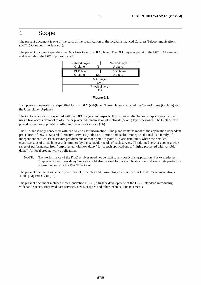
The present document specifies the Data Link Control (DLC) layer. The DLC layer is part 4 of the DECT CI standard and layer 2b of the DECT protocol stack.
Network layer Network layer C-plane (3) U-plane
DLC layer DLC layer C-plane (2b) U-plane
MAC layer (2a)
Physical layer (1)
Figure 1.1
Two planes of operation are specified for this DLC (sub)layer. These planes are called the Control plane (C-plane) and the User plane (U-plane).
The C-plane is mostly concerned with the DECT signalling aspects. It provides a reliable point-to-point service that uses a link access protocol to offer error protected transmission of Network (NWK) layer messages. The C-plane also provides a separate point-to-multipoint (broadcast) service (Lb).
The U-plane is only concerned with end-to-end user information. This plane contains most of the application dependent procedures of DECT. Several alternative services (both circuit-mode and packet-mode) are defined as a family of independent entities. Each service provides one or more point-to-point U-plane data links, where the detailed characteristics of those links are determined by the particular needs of each service. The defined services cover a wide range of performance, from "unprotected with low delay" for speech applications to "highly protected with variable delay", for local area network applications.
NOTE: The performance of the DLC services need not be tight to any particular application. For example the "unprotected with low delay" service could also be used for data applications, e.g. if some data protection is provided outside the DECT protocol.
The present document uses the layered model principles and terminology as described in ITU-T Recommendations X.200 [14] and X.210 [15].
The present document includes New Generation DECT, a further development of the DECT standard introducing wideband speech, improved data services, new slot types and other technical enhancements.
ETSI
ETSI EN 300 175-4 V2.4.1 (2012-04) 13
2 References References are either specific (identified by date of publication and/or edition number or version number) or non-specific. For specific references, only the cited version applies. For non-specific references, the latest version of the reference document (including any amendments) applies.
Referenced documents which are not found to be publicly available in the expected location might be found at http://docbox.etsi.org/Reference.
NOTE: While any hyperlinks included in this clause were valid at the time of publication ETSI cannot guarantee their long term validity.
2.1 Normative references The following referenced documents are necessary for the application of the present document.
[1] ETSI EN 300 175-1: "Digital Enhanced Cordless Telecommunications (DECT); Common Interface (CI); Part 1: Overview".
[2] ETSI EN 300 175-2: "Digital Enhanced Cordless Telecommunications (DECT); Common Interface (CI); Part 2: Physical Layer (PHL)".
[3] ETSI EN 300 175-3: "Digital Enhanced Cordless Telecommunications (DECT); Common Interface (CI); Part 3: Medium Access Control (MAC) layer".
[4] Void.
[5] ETSI EN 300 175-5: "Digital Enhanced Cordless Telecommunications (DECT); Common Interface (CI); Part 5: Network (NWK) layer".
[6] ETSI EN 300 175-6: "Digital Enhanced Cordless Telecommunications (DECT); Common Interface (CI); Part 6: Identities and addressing".
[7] Void.
[8] ETSI EN 300 175-8: "Digital Enhanced Cordless Telecommunications (DECT); Common Interface (CI); Part 8: Speech and audio coding and transmission".
[9] ETSI TS 144 006: "Digital cellular telecommunications system (Phase 2+); Mobile Station - Base Stations System (MS - BSS) interface Data Link (DL) layer specification (3GPP TS 44.006)".
[10] ITU-T Recommendation Q.920: "ISDN user-network interface data link layer - General aspects".
[11] ITU-T Recommendation Q.921: "ISDN user-network interface - Data link layer specification".
[12] ITU-T Recommendation V.42: "Error-correcting procedures for DCEs using asynchronous-to-synchronous conversion".
[13] ITU-T Recommendation V.110: "Support by an ISDN of data terminal equipments with V-Series type interfaces".
[14] ITU-T Recommendation X.200: "Information technology - Open Systems Interconnection - Basic Reference Model: The basic model".
[15] ITU-T Recommendation X.210: "Information technology - Open Systems Interconnection - Basic Reference Model: Conventions for the definition of OSI services".
[16] ISO/IEC 8073: "Information technology - Open Systems Interconnection - Protocol for providing the connection-mode transport service".
[17] ETSI EN 301 649: "Digital Enhanced Cordless Telecommunications (DECT); DECT Packet Radio Service (DPRS)".
ETSI
ETSI EN 300 175-4 V2.4.1 (2012-04) 14
2.2 Informative references The following referenced documents are not necessary for the application of the present document but they assist the user with regard to a particular subject area.
[i.1] ETSI TR 101 178: "Digital Enhanced Cordless Telecommunications (DECT); A High Level Guide to the DECT Standardization".
[i.2] ETSI ETR 043: "Digital Enhanced Cordless Telecommunications (DECT); Common Interface (CI); Services and facilities requirements specification".
[i.3] ITU-T Recommendation I.122: "Framework for frame mode bearer services".
[i.4] ITU-T Recommendation V.24: "List of definitions for interchange circuits between Data Terminal Equipment (DTE) and data circuit-terminating equipment (DCE)".
[i.5] IETF RFC 4749: "RTP Payload Format for the G.729.1 Audio Codec".
3 Definitions, symbols and abbreviations
3.1 Definitions For the purposes of the present document, the terms and definitions given in EN 300 175-1 [1] apply.
3.2 Symbols and abbreviations For the purposes of the present document, the following symbols and abbreviations apply:
AAL ATM Adaptation Layers ACK ACKnowledgement ADU Adapted Data Unit ALI Assigned Link Identifier AMCI Advanced MAC Connection Identifier ARQ Automatic Repeat reQuest ASM Assigned link identifier with Synchronous Mode ATM Asynchronous Transfer Mode BCH Bose-Chaudhuri-Hochquenghem BER Bit Error Ratio BFI Bad Frame Indicator BMCI Basic MAC Connection Identifier BRAT Basic RATe adaption service BS A logical channel to the MAC layer
C/R Command/Response bit CHO Connection HandOver CHP Connection Handover Pending CI Common Interface C-plane Control plane CRC Cyclic Redundancy Check CTS Clear To Send (see ITU-T recommendation V.24 [i.4]) DCD Data Carrier Detect (see ITU-T recommendation V.24 [i.4]) DECT Digital Enhanced Cordless Telecommunications DIC DECT Independent Clocking DISC DISConnect DLC Data Link Control DLEI Data Link Endpoint Identifier (DLC layer) DLI Data Link Identifier (DLC layer) DM Disconnect Mode
ETSI
ETSI EN 300 175-4 V2.4.1 (2012-04) 15
E+U type B-field multiplexer mode when the slot carries U-plane data (channel IPF) AND signalling
(channels GF and M)
ECN Exchanged Connection Number (DLC/MAC layer) EFREL Enhanced Frame RELay ESC ESCape EXOR EXclusive OR FBN Frame Buffer (Unprotected)
FBP Frame Buffer (Protected)
FBx Frame Buffer x FCS Frame Check Sequence FEC Forward Error Correction service FIFO First-In-First-Out FLEN Frame LENgth FP Fixed Part FREL Frame RELay service FSWI Frame SWItching service FT Fixed radio Termination FU DECT DLC U-Plane Frame format GBN Go Back N GF a logical channel to the MAC layer
HLM High Level Modulation HOV HandOVer flag IN higher layer Information channel (uNprotected), (logical channels to the MAC layer)
INA higher layer Information channel (unprotected), minimum delay operation
INB higher layer Information channel (unprotected), normal delay operation
IP higher layer Information channel (Protected), (logical channels to the MAC layer)
IP Internet Protocol IPF higher layer Information channel (protected) transported multiplexed with signalling in the E+U
type slots IPM higher layer Information channel (protected) with multi subfield format
IPMR higher layer Information channel (protected) with multi subfield format, with error correction
using MOD-2 retransmission mechanism IPQ higher layer Information channel (protected) with single subfield format
IPQR higher layer Information channel (protected) with single subfield format, with error correction
using MOD-2 retransmission mechanism IPX higher layer Information channel, encodec protected, minimum delay operation
ISDN Integrated Services Digital Network IWF InterWorking Function IWU InterWorking Unit LAPC DLC layer C-plane upper protocol entity LAPD Link Access Procedure on the D-channel LAPM Link Access Procedure for Modems (see ITU-T Recommendation V.42 [i.4]) LAPU Link Access Protocol User Lb DLC layer C-plane protocol entity for broadcast service Lc DLC layer C-plane lower protocol entity LCE Link Control Entity LCN Logical Connection Number (DLC/MAC layer) LI Length Indicator LLME Lower Layer Management Entity LLN Logical Link Number (DLC layer) lsb least significant bit LSIG Link SIGnature LU DECT DLC U-Plane Service LUx LAP-U service x MAC Medium Access Control MBS Maximum Bit rate (LU12) MCEI MAC Connection Endpoint Identification MCI MAC Connection Identifier
ETSI
ETSI EN 300 175-4 V2.4.1 (2012-04) 16
MCS Multi-Channel Set MDU Multiplexed Data Unit MOS Mean Opinion Score msb most significant bit N(S) Send sequence number NACK Negative ACKnowledgement NLF New Link Flag NWK NetWorK PA PArity PAD Packet Assembler/Disassembler PDU Protocol Data Unit PMID Portable part MAC IDentity (MAC layer) PP Portable Part PT Portable radio Termination RA Rate Adaptation RAVE Rate Adaption for V. series Equipment REJ REJect RES REServed RFP Radio Fixed Part RN Receive sequence Numbers RNR Receive Not Ready RR Receive Ready RS Receive Sequence RSN Receive Sequence Number SABM Set Async Bal Mode SAP Service Access Point SAPI Service Access Point Identifier SCBO Synchronous Continuous Bitstream Oriented SDU Service Data Unit SEL SELective SN Sequence Numbers SRAT Secondary RATe adaption service TAF Terminal Adaptation Function TCP Transmission Control Protocol TDMA Time Division Multiple Access TRUP TRansparent UnProtected service UA Unnumbered Ack UCN U-plane Channel Number UI Unnumbered Information ULEI U-plane Link Endpoint Identifier ULI Unassigned Link Identifier ULN U-plane Link Number UNF UNprotected Framed service U-plane User plane V(R) Receive state variable V(S) Send state variable
4 Data Link Control (DLC) layer overview
4.1 General The DLC layer shall contain two independent planes of protocol as shown in figures 4.2.1 and 4.3.1:
• the C-plane; and
• the U-plane.
C-plane (see figure 4.2.1): the C-plane is the control plane of the DECT protocol stacks, which shall contain all of the internal DECT protocol control, but may also include some external user information (and user control).
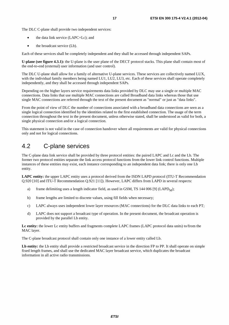
ETSI
ETSI EN 300 175-4 V2.4.1 (2012-04) 17
The DLC C-plane shall provide two independent services:
• the data link service (LAPC+Lc); and
• the broadcast service (Lb).
Each of these services shall be completely independent and they shall be accessed through independent SAPs.
U-plane (see figure 4.3.1): the U-plane is the user plane of the DECT protocol stacks. This plane shall contain most of the end-to-end (external) user information (and user control).
The DLC U-plane shall allow for a family of alternative U-plane services. These services are collectively named LUX, with the individual family members being named LU1, LU2, LU3, etc. Each of these services shall operate completely independently, and they shall be accessed through independent SAPs.
Depending on the higher layers service requirements data links provided by DLC may use a single or multiple MAC connections. Data links that use multiple MAC connections are called Broadband data links whereas those that use single MAC connections are referred through the text of the present document as "normal" or just as "data links".
From the point of view of DLC the number of connections associated with a broadband data connections are seen as a single logical connection identified by the identities related to the first established connection. The usage of the term connection throughout the text in the present document, unless otherwise stated, shall be understood as valid for both, a single physical connection and/or a logical connection.
This statement is not valid in the case of connection handover where all requirements are valid for physical connections only and not for logical connections.
4.2 C-plane services The C-plane data link service shall be provided by three protocol entities: the paired LAPC and Lc and the Lb. The former two protocol entities separate the link access protocol functions from the lower link control functions. Multiple instances of these entities may exist, each instance corresponding to an independent data link; there is only one Lb entity.
LAPC entity: the upper LAPC entity uses a protocol derived from the ISDN LAPD protocol (ITU-T Recommendation Q.920 [10] and ITU-T Recommendation Q.921 [11]). However, LAPC differs from LAPD in several respects:
a) frame delimiting uses a length indicator field, as used in GSM, TS 144 006 [9] (LAPDM);
b) frame lengths are limited to discrete values, using fill fields when necessary;
c) LAPC always uses independent lower layer resources (MAC connections) for the DLC data links to each PT;
d) LAPC does not support a broadcast type of operation. In the present document, the broadcast operation is provided by the parallel Lb entity.
Lc entity: the lower Lc entity buffers and fragments complete LAPC frames (LAPC protocol data units) to/from the MAC layer.
The C-plane broadcast protocol shall contain only one instance of a lower entity called Lb.
Lb entity: the Lb entity shall provide a restricted broadcast service in the direction FP to PP. It shall operate on simple fixed length frames, and shall use the dedicated MAC layer broadcast service, which duplicates the broadcast information in all active radio transmissions.
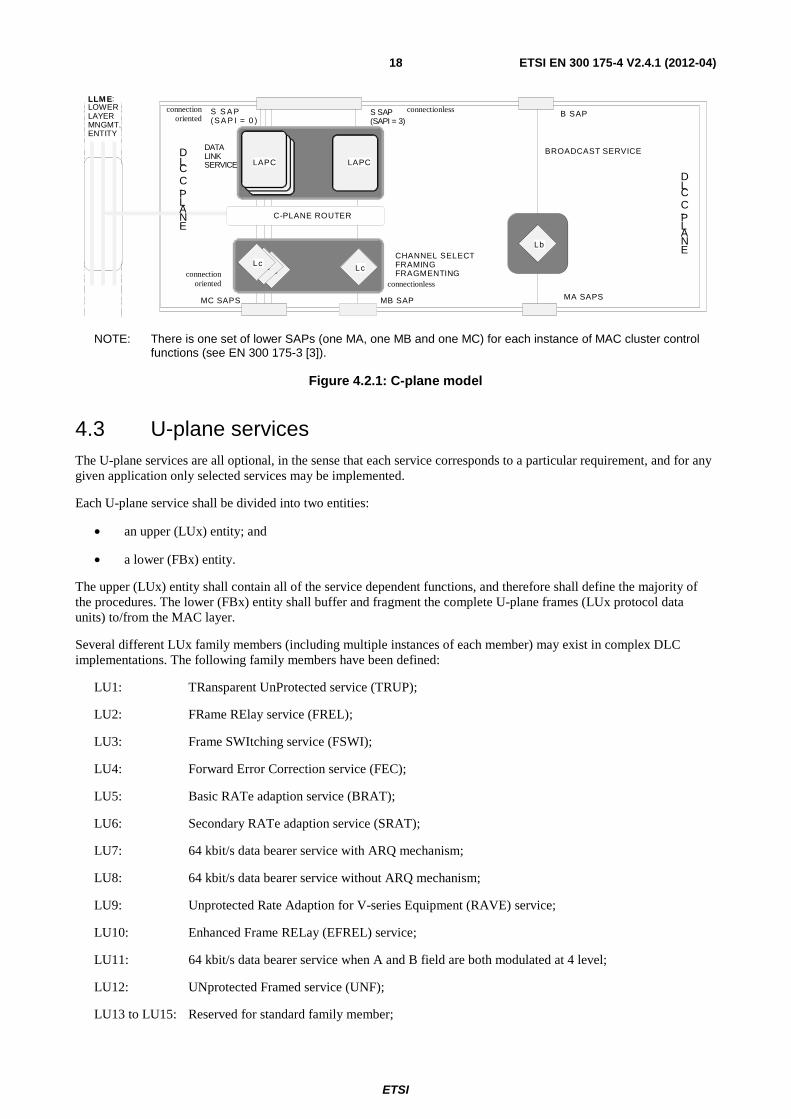
ETSI
ETSI EN 300 175-4 V2.4.1 (2012-04) 18
L c
L A P C L A P C L A P C
L c L c C H A N N E L S E L E C T F R A M I N G F R A G M E N T I N G
B S A P
L c L c
B R O A D C A S T S E R V I C E
M A S A P S
L A P C
L b
L L M E : L O W E R L A Y E R M N G M T . E N T I T Y
D L C C - P L A N E
D L C C - P L A N E
M B S A P M C S A P S
S S A P ( S A P I = 0 )
S S A P ( S A P I = 3 )
C - P L A N E R O U T E R
D A T A L I N K S E R V I C E
connection oriented
connection oriented
connectionless
connectionless
NOTE: There is one set of lower SAPs (one MA, one MB and one MC) for each instance of MAC cluster control functions (see EN 300 175-3 [3]).
Figure 4.2.1: C-plane model
4.3 U-plane services The U-plane services are all optional, in the sense that each service corresponds to a particular requirement, and for any given application only selected services may be implemented.
Each U-plane service shall be divided into two entities:
• an upper (LUx) entity; and
• a lower (FBx) entity.
The upper (LUx) entity shall contain all of the service dependent functions, and therefore shall define the majority of the procedures. The lower (FBx) entity shall buffer and fragment the complete U-plane frames (LUx protocol data units) to/from the MAC layer.
Several different LUx family members (including multiple instances of each member) may exist in complex DLC implementations. The following family members have been defined:
LU1: TRansparent UnProtected service (TRUP);
LU2: FRame RElay service (FREL);
LU3: Frame SWItching service (FSWI);
LU4: Forward Error Correction service (FEC);
LU5: Basic RATe adaption service (BRAT);
LU6: Secondary RATe adaption service (SRAT);
LU7: 64 kbit/s data bearer service with ARQ mechanism;
LU8: 64 kbit/s data bearer service without ARQ mechanism;
LU9: Unprotected Rate Adaption for V-series Equipment (RAVE) service;
LU10: Enhanced Frame RELay (EFREL) service;
LU11: 64 kbit/s data bearer service when A and B field are both modulated at 4 level;
LU12: UNprotected Framed service (UNF);
LU13 to LU15: Reserved for standard family member;

ETSI
ETSI EN 300 175-4 V2.4.1 (2012-04) 19
LU16: ESCape for non-standard family (ESC).
There shall be provision for three additional standard family members to be added to future versions of the present document. There shall also be provision for one non-standard family member; this is provided by means of a general purpose "escape" route that can be used for implementation specific protocols.
NOTE 1: The LU4 services are for further study.
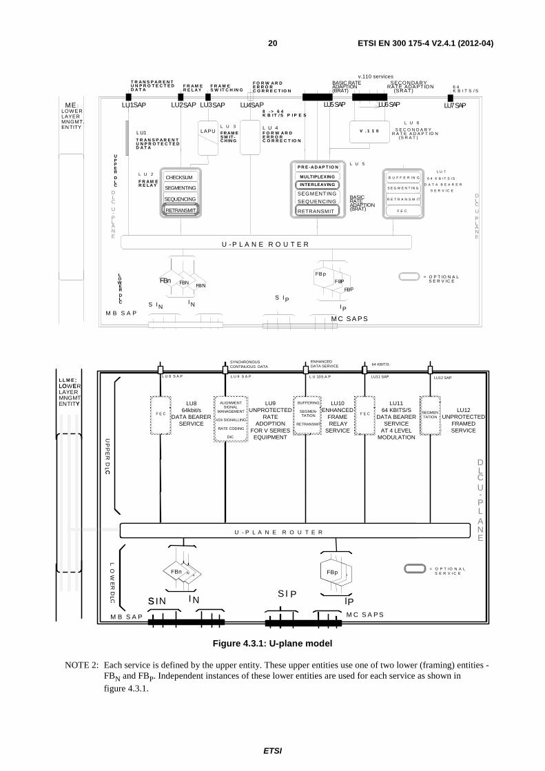
ETSI
ETSI EN 300 175-4 V2.4.1 (2012-04) 20
L U 2
L U 5
L U 6L U 3
S E C O N D A R YR A T E A D A P T IO N
(S R A T )
= O P T IO N A LS E R V IC E
DLC
U-PLANE
LAPUL U 4
DLCU-PLANE
ME :LOWERLAYERMNGMT.EN TITY
SECONDARYRATE ADAPTION
(SRAT)
BASICRATEADAPTIO(BRAT)
BASIC RATEADAPTION(BRAT)
RETRANSMIT
FBpFBP
CHECKSUM
SEGMENTING
SEQUENCING
RETRANSMIT
FBNB
SEGM ENTING
SEQUENCING
P R E -A D AP T IO N
MULTIPLEXING
INTERLEAVING
8 - > 6 4K B I T / S P I P E S
F R A M ER E L A Y
F R A M ES W IT C H IN G
F O R W A R DE R R O RC O R R E C T IO N
LU1 AP LU4SAPLU3SAP LU5SAP LU6SAP
U -P L A N E R O U T E R
M C S A P S
FBn
UPPERDLC
LOWERDLC
F O R W A R DE R R O RC O R R E C T IO N
T R A N S P A R E N TU N P R O T E C T E DD A T A
V . 1 1 0
F R A M ER E LA Y
T R A N S P A R E N TU N P R O T E C T E DD A T A
6 4K B I T S / S
LU7SAP
L U 7
6 4 K B I T S / S
D A T A B E A R E R
S E R V I C E
M B S A P
S I I NS I P
I PN
v.110 services
S U2SAPL
N
B U F F E R I N G
F E C
S E G M E N T IN G
R E T R A N S M I T
L U1 FR AM ES W IT-C H IN G
F N
FB p
= O P T IO N A LS E R V I C E
L L M E :LOWERLAYERMNGMT.ENTITY
F B pF B PF B NF B N FBp
U - P L A N E R O U T E R
M C S A P S
FBn
S I I NS I P
IPN
L U 8 S A P
LU864kbit/s
DATA BEARERSERVICE
F E C
BUFFERING
SEGMEN-TATION
RETRANSMIT
ALIGNMENTSIGNALMANAGEMENT
V24
SIGNALLING
RATE CODING
DIC
F E C
M B S A P
:LO E
Y
F B pF B PF B NF B N FBp
U - P L A N E R O U T E R
FBn
S
F E C
BUFFERING
SEGMEN-TATION
RETRANSMIT
ALIGNMENTSIGNAL
MANAGEMENT
V24 SIGNALLING
RATE CODING
DIC
F E C
UP
PE
RD
L CCL
OW
ER
DL C
L U 9 S A P L U 10S A P
DLCU-PLANE
LU9UNPROTECTED
RATEADOPTION
FOR V SERIES EQUIPMENT
LU10ENHANCED
FRAME RELAY
SERVICE
LU1164 KBITS/S
DATA BEARERSERVICE
AT 4 LEVELMODULATION
SYNCHRONOUS CONTINUOUS DATA
ENHANCED DATA SERVICE 64 KBIT/S
LU11 SAP
F E C
SEGMENTATION
LU12UNPROTECTED
FRAMEDSERVICE
LU12 SAP
Figure 4.3.1: U-plane model
NOTE 2: Each service is defined by the upper entity. These upper entities use one of two lower (framing) entities - FBN and FBP. Independent instances of these lower entities are used for each service as shown in
figure 4.3.1.
ETSI
ETSI EN 300 175-4 V2.4.1 (2012-04) 21
NOTE 3: There is one set of lower SAPs (one MA, one MB and one MC) for each instance of MAC cluster control functions (see EN 300 175-3 [3]).
4.4 Lower Layer Management Entity (LLME) The LLME shall provide co-ordination and control for these independent C-plane and U-plane processes. In particular the LLME shall control the routing of the C-plane and U-plane frames to and from the available MAC connections, and shall control the opening and closing (and handover) of the MAC connections in response to service demands. The LLME operations are defined in general terms in order to allow for different implementations.
5 C-plane service characteristics
5.1 Data link service (LAPC+Lc)
5.1.1 General
The data link service (LAPC+Lc) shall be accessed via the S SAP. Three classes of service are defined:
• Class U: an unacknowledged service;
• Class A: a (single frame) acknowledged service;
• Class B: a (multiple frame) acknowledged service.
Each LAPC instance shall only support one class of operation to provide a single data link between one FT and one PT.
NOTE 1: Class U may provide a data link to more than one PT when using connectionless MAC services.
Class B multiple frame operation shall require both sides to support three phases of additional procedures:
1) establishment of class B multi-frame operation;
2) maintenance of class B multi-frame operation (including acknowledged information transfer);
3) release of class B multi-frame operation.
The complete service for one data link shall be provided by a pair of protocol entities called LAPC and Lc, using a single MAC connection. These two protocol entities separate the more conventional upper functions (LAPC) from the more unusual lower functions (Lc).
Multiple instances of LAPC and of Lc entities may exist in the FT, but typically only one LAPC and one Lc entity will exist in each PT. Each instance in the FT shall be connected to only one peer instance in one PT.
Multiple (independent) MAC connections may exist to a single PT, but each instance of Lc shall only use the services of one MAC connection.
NOTE 2: A PT may contain multiple instances of LAPC+Lc. However, in many cases a PT may only require the services of one LAPC and one Lc instance. These single instances may support more than one NWK layer call.
When serving a broadband data link the LAPC+Lc may use any of the connections (identified by their ECN) belonging to the logical connection associated with the link.
LAPC shall provide functions for:
a) the provision and control of one data link;
b) segmentation of long layer 3 information fields;
c) error detection (timeout or protocol);
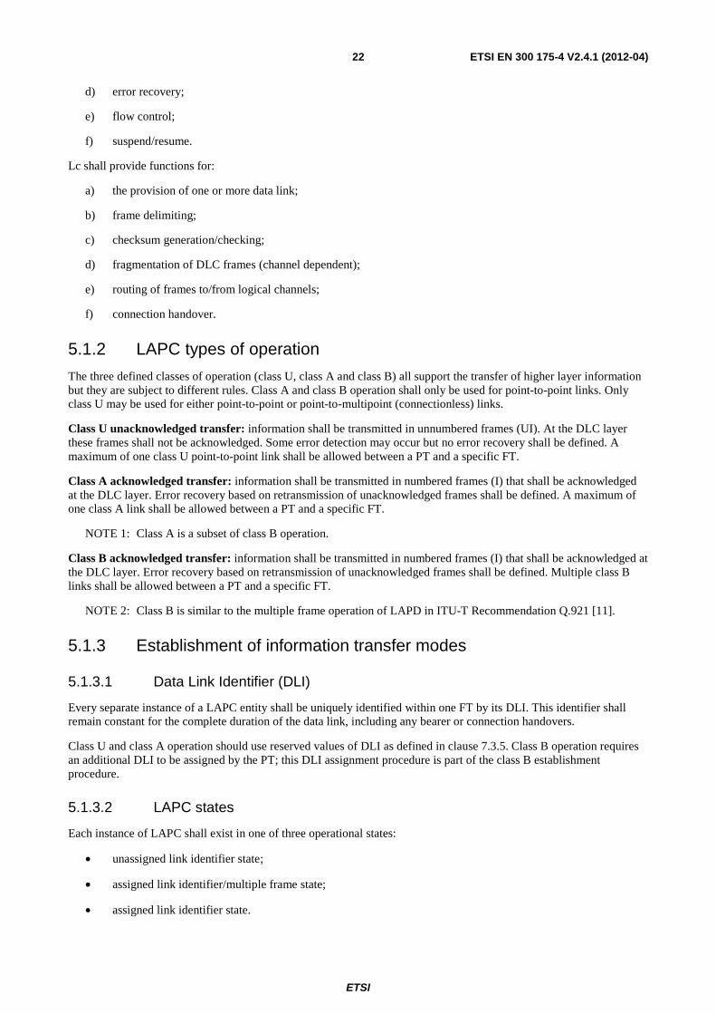
ETSI
ETSI EN 300 175-4 V2.4.1 (2012-04) 22
d) error recovery;
e) flow control;
f) suspend/resume.
Lc shall provide functions for:
a) the provision of one or more data link;
b) frame delimiting;
c) checksum generation/checking;
d) fragmentation of DLC frames (channel dependent);
e) routing of frames to/from logical channels;
f) connection handover.
5.1.2 LAPC types of operation
The three defined classes of operation (class U, class A and class B) all support the transfer of higher layer information but they are subject to different rules. Class A and class B operation shall only be used for point-to-point links. Only class U may be used for either point-to-point or point-to-multipoint (connectionless) links.
Class U unacknowledged transfer: information shall be transmitted in unnumbered frames (UI). At the DLC layer these frames shall not be acknowledged. Some error detection may occur but no error recovery shall be defined. A maximum of one class U point-to-point link shall be allowed between a PT and a specific FT.
Class A acknowledged transfer: information shall be transmitted in numbered frames (I) that shall be acknowledged at the DLC layer. Error recovery based on retransmission of unacknowledged frames shall be defined. A maximum of one class A link shall be allowed between a PT and a specific FT.
NOTE 1: Class A is a subset of class B operation.
Class B acknowledged transfer: information shall be transmitted in numbered frames (I) that shall be acknowledged at the DLC layer. Error recovery based on retransmission of unacknowledged frames shall be defined. Multiple class B links shall be allowed between a PT and a specific FT.
NOTE 2: Class B is similar to the multiple frame operation of LAPD in ITU-T Recommendation Q.921 [11].
5.1.3 Establishment of information transfer modes
5.1.3.1 Data Link Identifier (DLI)
Every separate instance of a LAPC entity shall be uniquely identified within one FT by its DLI. This identifier shall remain constant for the complete duration of the data link, including any bearer or connection handovers.
Class U and class A operation should use reserved values of DLI as defined in clause 7.3.5. Class B operation requires an additional DLI to be assigned by the PT; this DLI assignment procedure is part of the class B establishment procedure.
5.1.3.2 LAPC states
Each instance of LAPC shall exist in one of three operational states:
• unassigned link identifier state;
• assigned link identifier/multiple frame state;
• assigned link identifier state.
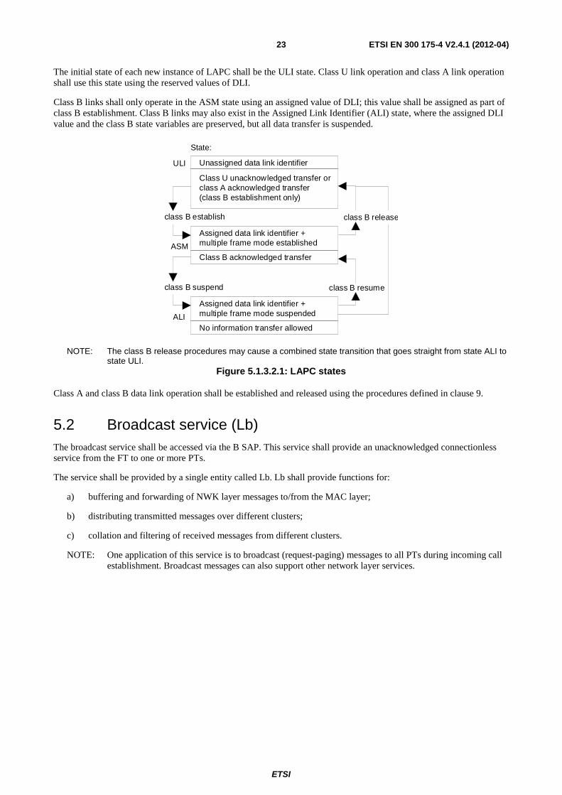
ETSI
ETSI EN 300 175-4 V2.4.1 (2012-04) 23
The initial state of each new instance of LAPC shall be the ULI state. Class U link operation and class A link operation shall use this state using the reserved values of DLI.
Class B links shall only operate in the ASM state using an assigned value of DLI; this value shall be assigned as part of class B establishment. Class B links may also exist in the Assigned Link Identifier (ALI) state, where the assigned DLI value and the class B state variables are preserved, but all data transfer is suspended.
Unassigned data link identifier
Class U unacknowledged transfer orclass A acknowledged transfer(class B establishment only)
State:
class B establish class B release
Assigned data link identifier +multiple frame mode established
Class B acknowledged transfer
class B suspend class B resume
Assigned data link identifier +multiple frame mode suspended
No information transfer allowedALI
ULI
ASM
NOTE: The class B release procedures may cause a combined state transition that goes straight from state ALI to state ULI.
Figure 5.1.3.2.1: LAPC states
Class A and class B data link operation shall be established and released using the procedures defined in clause 9.
5.2 Broadcast service (Lb) The broadcast service shall be accessed via the B SAP. This service shall provide an unacknowledged connectionless service from the FT to one or more PTs.
The service shall be provided by a single entity called Lb. Lb shall provide functions for:
a) buffering and forwarding of NWK layer messages to/from the MAC layer;
b) distributing transmitted messages over different clusters;
c) collation and filtering of received messages from different clusters.
NOTE: One application of this service is to broadcast (request-paging) messages to all PTs during incoming call establishment. Broadcast messages can also support other network layer services.
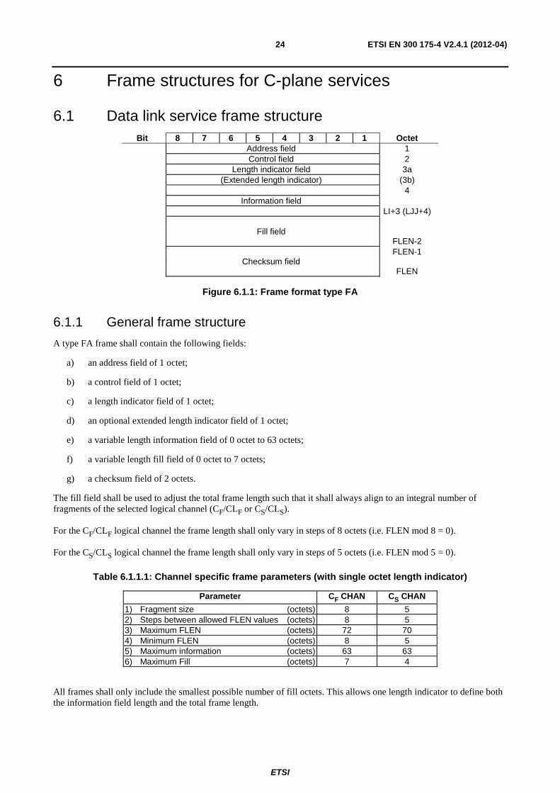
ETSI
ETSI EN 300 175-4 V2.4.1 (2012-04) 24
6 Frame structures for C-plane services
6.1 Data link service frame structure Bit 8 7 6 5 4 3 2 1 Octet
Address field 1 Control field 2 Length indicator field 3a (Extended length indicator) (3b) 4 Information field LI+3 (LJJ+4) Fill field FLEN-2 FLEN-1 Checksum field FLEN
Figure 6.1.1: Frame format type FA
6.1.1 General frame structure
A type FA frame shall contain the following fields:
a) an address field of 1 octet;
b) a control field of 1 octet;
c) a length indicator field of 1 octet;
d) an optional extended length indicator field of 1 octet;
e) a variable length information field of 0 octet to 63 octets;
f) a variable length fill field of 0 octet to 7 octets;
g) a checksum field of 2 octets.
The fill field shall be used to adjust the total frame length such that it shall always align to an integral number of fragments of the selected logical channel (CF/CLF or CS/CLS).
For the CF/CLF logical channel the frame length shall only vary in steps of 8 octets (i.e. FLEN mod 8 = 0).
For the CS/CLS logical channel the frame length shall only vary in steps of 5 octets (i.e. FLEN mod 5 = 0).
Table 6.1.1.1: Channel specific frame parameters (with single octet length indicator)
Parameter CF CHAN CS CHAN
1) Fragment size (octets) 8 5 2) Steps between allowed FLEN values (octets) 8 5 3) Maximum FLEN (octets) 72 70 4) Minimum FLEN (octets) 8 5 5) Maximum information (octets) 63 63 6) Maximum Fill (octets) 7 4
All frames shall only include the smallest possible number of fill octets. This allows one length indicator to define both the information field length and the total frame length.
ETSI
ETSI EN 300 175-4 V2.4.1 (2012-04) 25
NOTE: During idle periods, the LAPC should not generate null frames (i.e. frames with no control purpose and with zero length information fields). This avoids causing the MAC layer to waste connection resources.
For details of the length indicator refer to clause 7.6.
6.1.2 Lc frame delimiting and transparency
Frame delimiting shall be provided by a combination of the MAC layer and the DLC layer Lc entity. The MAC layer shall always align Lc fragments to physical slot boundaries. This is described in EN 300 175-2 [2] and this timing shall always be preserved.
A DLC frame shall only start on a fragment boundary. The end of a multi-fragment frame should be identified by examining the length indicator field. Therefore the Lc should process all frames in the order they are received (in sequence).
NOTE 1: This delimiting technique avoids the need for flag octets, and there are no restrictions on the allowable bit sequences in any of the fields.
NOTE 2: The MAC layer is expected to provide a reliable connection-orientated service, with a residual fragment error rate better than 10-4.
The Lc entity shall use the following procedure to establish frame synchronization (i.e. locate the start of the first frame) and to maintain frame synchronization.
Frame synchronization: in order to establish frame synchronization, an unsynchronized Lc (receive) entity shall treat each fragment as the first fragment of a frame, treating octets 3a (and 3b) as a length indicator field to determine the frame length. Successful frame synchronization shall be identified by checksum success. Any checksum failure on a subsequent frame shall cause the Lc entity to repeat this procedure until frame synchronization is re-established.
When possible, a single fragment frame (i.e. the shortest possible frame) should be used by both entities for their first transmission or at link resumption.
6.1.3 Transmission order
The physical transmission order shall be controlled by the MAC layer as defined in EN 300 175-3 [3]. This MAC layer ordering shall use the octet numbering and bit numbering as shown on figure 6.1.1.
The operations across the DLC layer/MAC layer boundary shall be such that the DLC entity sending a frame can assume this temporal order of the frame, and that the entity receiving the frame can reconstruct it with its assumed temporal order.
6.1.4 Routing to logical channels
Each Lc frame shall only be sent in one of two logical channels, CF or CS (CLF or CLS in the case for connectionless
service). These channels are independent.
A frame retransmitted by LAPC, shall be regarded as a different frame by Lc. No duplication of frames by the Lc entity is allowed.
The selection of the logical channel shall be controlled by the LLME (see clause 10.2.5).
6.1.4.1 CF/CLF logical channel
The complete frame shall be fragmented into 8 octet fragments. One or more fragments may be sent in each MAC_CO_DATA-req primitive and received in each MAC_CO_DATA-ind primitive. Sequence numbers shall not be added because the MAC is expected to always preserve the order of transmission; fragments shall be delivered in the order that they were transmitted.
NOTE: The checksum is added to support frame synchronization and to protect against slot theft and other residual errors.
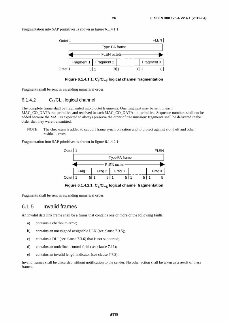
ETSI
ETSI EN 300 175-4 V2.4.1 (2012-04) 26
Fragmentation into SAP primitives is shown in figure 6.1.4.1.1.
Octet 1
Octet 1
Fragment 1 Fragment 2 Fragment X
8 1 1 8 8 1 8
Type FA frame
FLEN
FLEN octets
Figure 6.1.4.1.1: CF/CLF logical channel fragmentation
Fragments shall be sent in ascending numerical order.
6.1.4.2 CS/CLS logical channel
The complete frame shall be fragmented into 5 octet fragments. One fragment may be sent in each MAC_CO_DATA-req primitive and received in each MAC_CO_DATA-ind primitive. Sequence numbers shall not be added because the MAC is expected to always preserve the order of transmission: fragments shall be delivered in the order that they were transmitted.
NOTE: The checksum is added to support frame synchronization and to protect against slot theft and other residual errors.
Fragmentation into SAP primitives is shown in figure 6.1.4.2.1.
F r a g 1
F L E N o c t e t s
T y p e F A f r a m e
O c t e t : 1
F L E N
5 1 5 1 5 1 5
O c t e t : 1
F r a g 2 F r a g 3 F r a g X
5 1
Figure 6.1.4.2.1: CS/CLS logical channel fragmentation
Fragments shall be sent in ascending numerical order.
6.1.5 Invalid frames
An invalid data link frame shall be a frame that contains one or more of the following faults:
a) contains a checksum error;
b) contains an unassigned assignable LLN (see clause 7.3.5);
c) contains a DLI (see clause 7.3.6) that is not supported;
d) contains an undefined control field (see clause 7.11);
e) contains an invalid length indicator (see clause 7.7.3).
Invalid frames shall be discarded without notification to the sender. No other action shall be taken as a result of these frames.
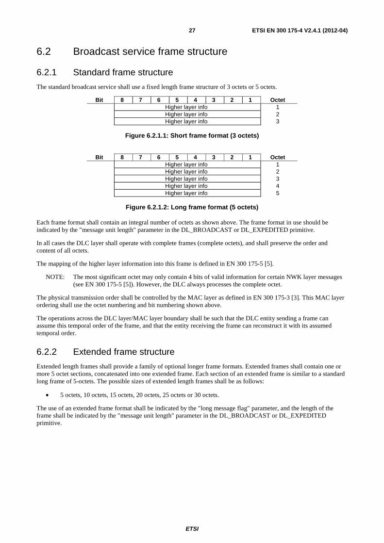
ETSI
ETSI EN 300 175-4 V2.4.1 (2012-04) 27
6.2 Broadcast service frame structure
6.2.1 Standard frame structure
The standard broadcast service shall use a fixed length frame structure of 3 octets or 5 octets.
Bit 8 7 6 5 4 3 2 1 Octet Higher layer info 1 Higher layer info 2 Higher layer info 3
Figure 6.2.1.1: Short frame format (3 octets)
Bit 8 7 6 5 4 3 2 1 Octet
Higher layer info 1 Higher layer info 2 Higher layer info 3 Higher layer info 4 Higher layer info 5
Figure 6.2.1.2: Long frame format (5 octets)
Each frame format shall contain an integral number of octets as shown above. The frame format in use should be indicated by the "message unit length" parameter in the DL_BROADCAST or DL_EXPEDITED primitive.
In all cases the DLC layer shall operate with complete frames (complete octets), and shall preserve the order and content of all octets.
The mapping of the higher layer information into this frame is defined in EN 300 175-5 [5].
NOTE: The most significant octet may only contain 4 bits of valid information for certain NWK layer messages (see EN 300 175-5 [5]). However, the DLC always processes the complete octet.
The physical transmission order shall be controlled by the MAC layer as defined in EN 300 175-3 [3]. This MAC layer ordering shall use the octet numbering and bit numbering shown above.
The operations across the DLC layer/MAC layer boundary shall be such that the DLC entity sending a frame can assume this temporal order of the frame, and that the entity receiving the frame can reconstruct it with its assumed temporal order.
6.2.2 Extended frame structure
Extended length frames shall provide a family of optional longer frame formats. Extended frames shall contain one or more 5 octet sections, concatenated into one extended frame. Each section of an extended frame is similar to a standard long frame of 5-octets. The possible sizes of extended length frames shall be as follows:
• 5 octets, 10 octets, 15 octets, 20 octets, 25 octets or 30 octets.
The use of an extended frame format shall be indicated by the "long message flag" parameter, and the length of the frame shall be indicated by the "message unit length" parameter in the DL_BROADCAST or DL_EXPEDITED primitive.
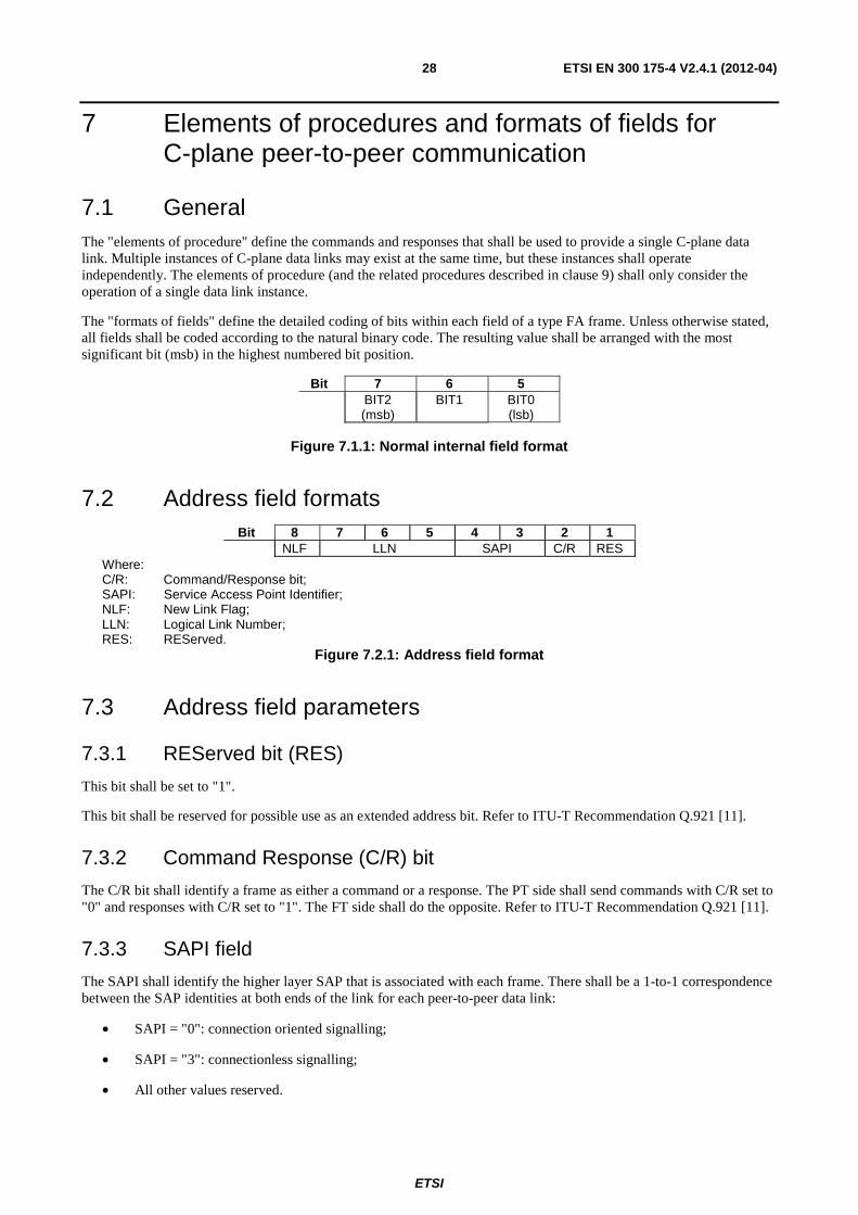
ETSI
ETSI EN 300 175-4 V2.4.1 (2012-04) 28
7 Elements of procedures and formats of fields for C-plane peer-to-peer communication
7.1 General The "elements of procedure" define the commands and responses that shall be used to provide a single C-plane data link. Multiple instances of C-plane data links may exist at the same time, but these instances shall operate independently. The elements of procedure (and the related procedures described in clause 9) shall only consider the operation of a single data link instance.
The "formats of fields" define the detailed coding of bits within each field of a type FA frame. Unless otherwise stated, all fields shall be coded according to the natural binary code. The resulting value shall be arranged with the most significant bit (msb) in the highest numbered bit position.
Bit 7 6 5 BIT2
(msb) BIT1
BIT0 (lsb)
Figure 7.1.1: Normal internal field format
7.2 Address field formats Bit 8 7 6 5 4 3 2 1
NLF LLN SAPI C/R RES Where: C/R: Command/Response bit; SAPI: Service Access Point Identifier; NLF: New Link Flag; LLN: Logical Link Number; RES: REServed.
Figure 7.2.1: Address field format
7.3 Address field parameters
7.3.1 REServed bit (RES)
This bit shall be set to "1".
This bit shall be reserved for possible use as an extended address bit. Refer to ITU-T Recommendation Q.921 [11].
7.3.2 Command Response (C/R) bit
The C/R bit shall identify a frame as either a command or a response. The PT side shall send commands with C/R set to "0" and responses with C/R set to "1". The FT side shall do the opposite. Refer to ITU-T Recommendation Q.921 [11].
7.3.3 SAPI field
The SAPI shall identify the higher layer SAP that is associated with each frame. There shall be a 1-to-1 correspondence between the SAP identities at both ends of the link for each peer-to-peer data link:
• SAPI = "0": connection oriented signalling;
• SAPI = "3": connectionless signalling;
• All other values reserved.
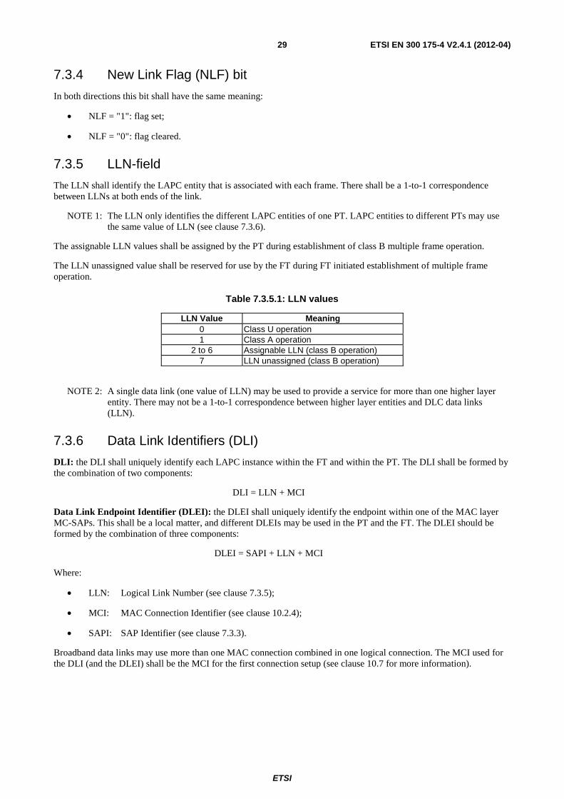
ETSI
ETSI EN 300 175-4 V2.4.1 (2012-04) 29
7.3.4 New Link Flag (NLF) bit
In both directions this bit shall have the same meaning:
• NLF = "1": flag set;
• NLF = "0": flag cleared.
7.3.5 LLN-field
The LLN shall identify the LAPC entity that is associated with each frame. There shall be a 1-to-1 correspondence between LLNs at both ends of the link.
NOTE 1: The LLN only identifies the different LAPC entities of one PT. LAPC entities to different PTs may use the same value of LLN (see clause 7.3.6).
The assignable LLN values shall be assigned by the PT during establishment of class B multiple frame operation.
The LLN unassigned value shall be reserved for use by the FT during FT initiated establishment of multiple frame operation.
Table 7.3.5.1: LLN values
LLN Value Meaning 0 Class U operation 1 Class A operation
2 to 6 Assignable LLN (class B operation) 7 LLN unassigned (class B operation)
NOTE 2: A single data link (one value of LLN) may be used to provide a service for more than one higher layer entity. There may not be a 1-to-1 correspondence between higher layer entities and DLC data links (LLN).
7.3.6 Data Link Identifiers (DLI)
DLI: the DLI shall uniquely identify each LAPC instance within the FT and within the PT. The DLI shall be formed by the combination of two components:
DLI = LLN + MCI
Data Link Endpoint Identifier (DLEI): the DLEI shall uniquely identify the endpoint within one of the MAC layer MC-SAPs. This shall be a local matter, and different DLEIs may be used in the PT and the FT. The DLEI should be formed by the combination of three components:
DLEI = SAPI + LLN + MCI
Where:
• LLN: Logical Link Number (see clause 7.3.5);
• MCI: MAC Connection Identifier (see clause 10.2.4);
• SAPI: SAP Identifier (see clause 7.3.3).
Broadband data links may use more than one MAC connection combined in one logical connection. The MCI used for the DLI (and the DLEI) shall be the MCI for the first connection setup (see clause 10.7 for more information).
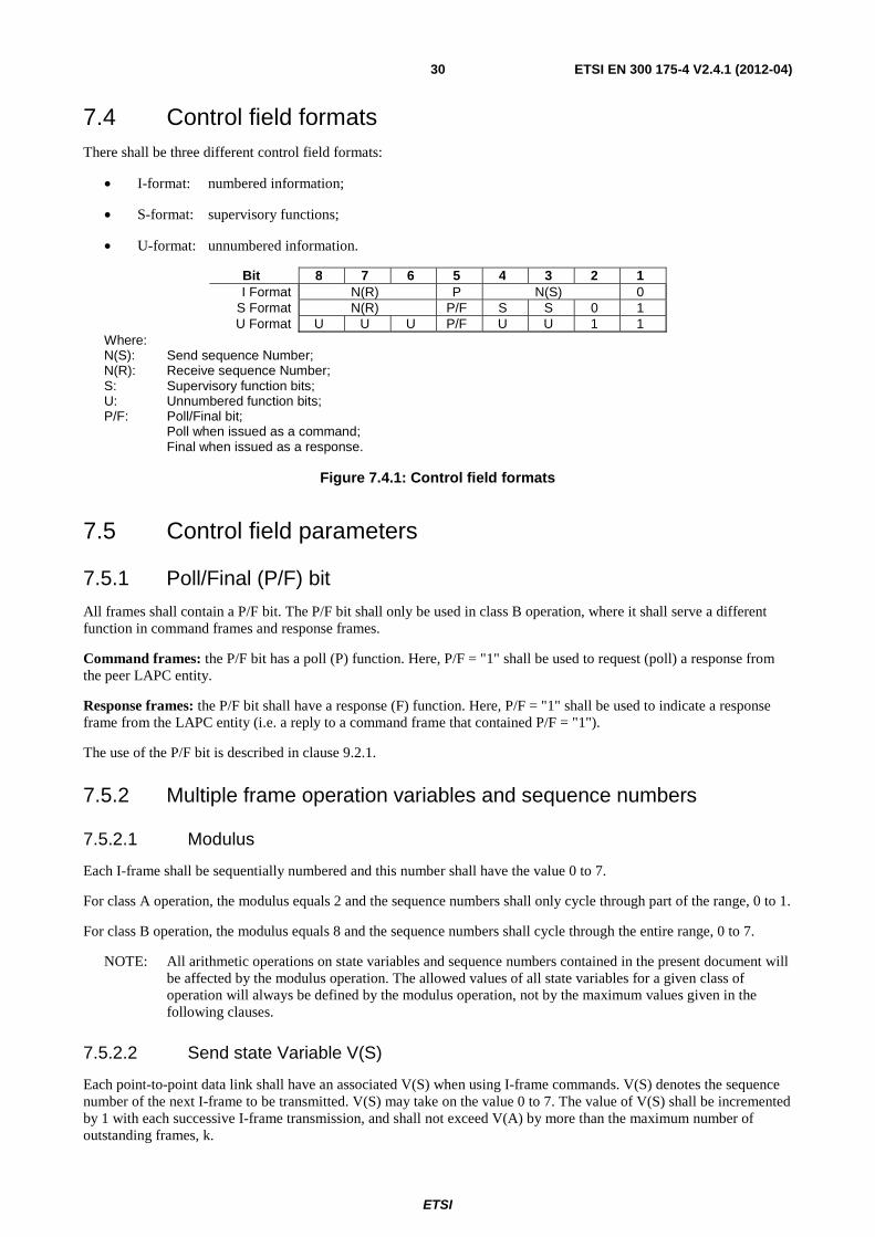
ETSI
ETSI EN 300 175-4 V2.4.1 (2012-04) 30
7.4 Control field formats There shall be three different control field formats:
• I-format: numbered information;
• S-format: supervisory functions;
• U-format: unnumbered information.
Bit 8 7 6 5 4 3 2 1 I Format N(R) P N(S) 0
S Format N(R) P/F S S 0 1 U Format U U U P/F U U 1 1
Where: N(S): Send sequence Number; N(R): Receive sequence Number; S: Supervisory function bits; U: Unnumbered function bits; P/F: Poll/Final bit; Poll when issued as a command; Final when issued as a response.
Figure 7.4.1: Control field formats
7.5 Control field parameters
7.5.1 Poll/Final (P/F) bit
All frames shall contain a P/F bit. The P/F bit shall only be used in class B operation, where it shall serve a different function in command frames and response frames.
Command frames: the P/F bit has a poll (P) function. Here, P/F = "1" shall be used to request (poll) a response from the peer LAPC entity.
Response frames: the P/F bit shall have a response (F) function. Here, P/F = "1" shall be used to indicate a response frame from the LAPC entity (i.e. a reply to a command frame that contained P/F = "1").
The use of the P/F bit is described in clause 9.2.1.
7.5.2 Multiple frame operation variables and sequence numbers
7.5.2.1 Modulus
Each I-frame shall be sequentially numbered and this number shall have the value 0 to 7.
For class A operation, the modulus equals 2 and the sequence numbers shall only cycle through part of the range, 0 to 1.
For class B operation, the modulus equals 8 and the sequence numbers shall cycle through the entire range, 0 to 7.
NOTE: All arithmetic operations on state variables and sequence numbers contained in the present document will be affected by the modulus operation. The allowed values of all state variables for a given class of operation will always be defined by the modulus operation, not by the maximum values given in the following clauses.
7.5.2.2 Send state Variable V(S)
Each point-to-point data link shall have an associated V(S) when using I-frame commands. V(S) denotes the sequence number of the next I-frame to be transmitted. V(S) may take on the value 0 to 7. The value of V(S) shall be incremented by 1 with each successive I-frame transmission, and shall not exceed V(A) by more than the maximum number of outstanding frames, k.
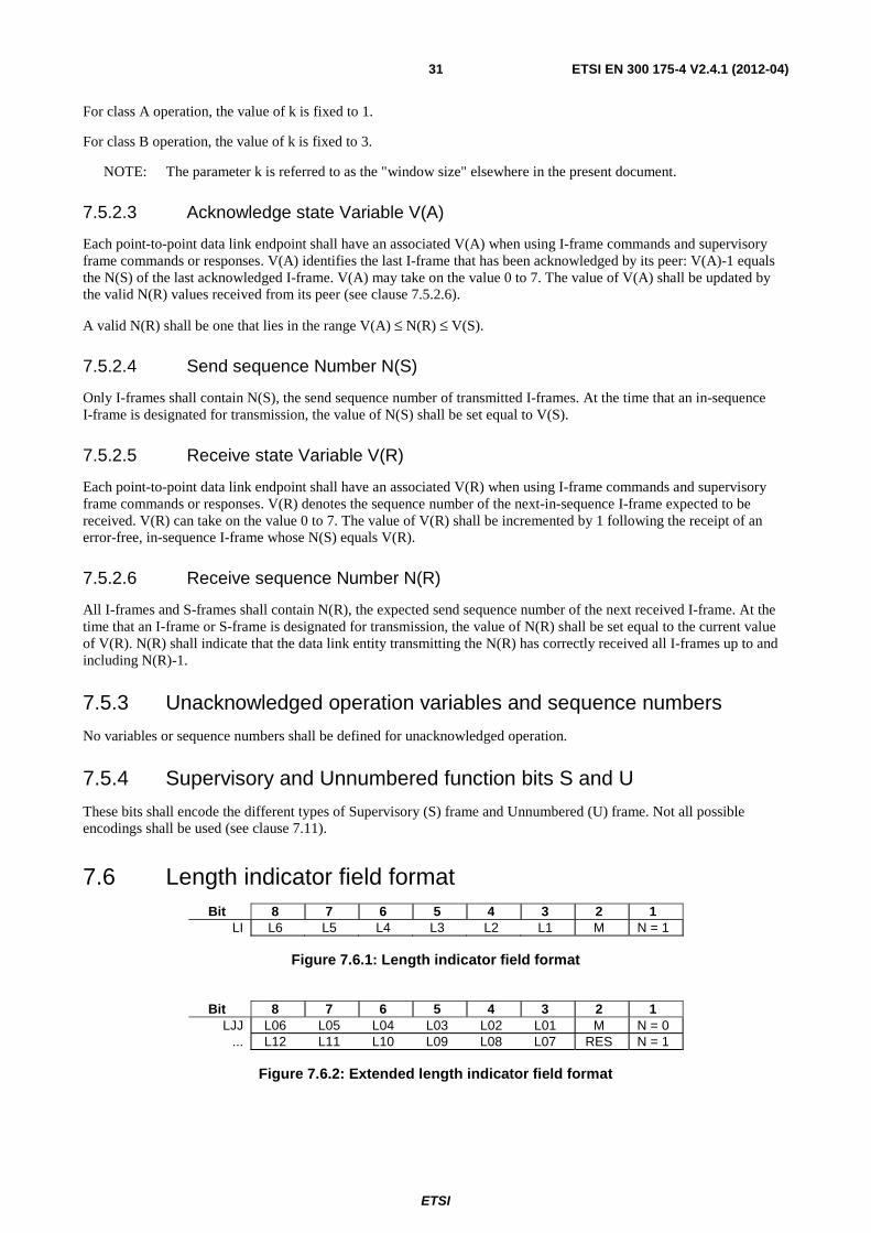
ETSI
ETSI EN 300 175-4 V2.4.1 (2012-04) 31
For class A operation, the value of k is fixed to 1.
For class B operation, the value of k is fixed to 3.
NOTE: The parameter k is referred to as the "window size" elsewhere in the present document.
7.5.2.3 Acknowledge state Variable V(A)
Each point-to-point data link endpoint shall have an associated V(A) when using I-frame commands and supervisory frame commands or responses. V(A) identifies the last I-frame that has been acknowledged by its peer: V(A)-1 equals the N(S) of the last acknowledged I-frame. V(A) may take on the value 0 to 7. The value of V(A) shall be updated by the valid N(R) values received from its peer (see clause 7.5.2.6).
A valid N(R) shall be one that lies in the range V(A) ≤ N(R) ≤ V(S).
7.5.2.4 Send sequence Number N(S)
Only I-frames shall contain N(S), the send sequence number of transmitted I-frames. At the time that an in-sequence I-frame is designated for transmission, the value of N(S) shall be set equal to V(S).
7.5.2.5 Receive state Variable V(R)
Each point-to-point data link endpoint shall have an associated V(R) when using I-frame commands and supervisory frame commands or responses. V(R) denotes the sequence number of the next-in-sequence I-frame expected to be received. V(R) can take on the value 0 to 7. The value of V(R) shall be incremented by 1 following the receipt of an error-free, in-sequence I-frame whose N(S) equals V(R).
7.5.2.6 Receive sequence Number N(R)
All I-frames and S-frames shall contain N(R), the expected send sequence number of the next received I-frame. At the time that an I-frame or S-frame is designated for transmission, the value of N(R) shall be set equal to the current value of V(R). N(R) shall indicate that the data link entity transmitting the N(R) has correctly received all I-frames up to and including N(R)-1.
7.5.3 Unacknowledged operation variables and sequence numbers
No variables or sequence numbers shall be defined for unacknowledged operation.
7.5.4 Supervisory and Unnumbered function bits S and U
These bits shall encode the different types of Supervisory (S) frame and Unnumbered (U) frame. Not all possible encodings shall be used (see clause 7.11).
7.6 Length indicator field format Bit 8 7 6 5 4 3 2 1
LI L6 L5 L4 L3 L2 L1 M N = 1
Figure 7.6.1: Length indicator field format
Bit 8 7 6 5 4 3 2 1
LJJ L06 L05 L04 L03 L02 L01 M N = 0 ... L12 L11 L10 L09 L08 L07 RES N = 1
Figure 7.6.2: Extended length indicator field format
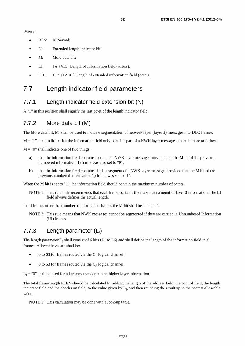
ETSI
ETSI EN 300 175-4 V2.4.1 (2012-04) 32
Where:
• RES: REServed;
• N: Extended length indicator bit;
• M: More data bit;
• LI: I ∈ {6..1} Length of Information field (octets);
• LJJ: JJ ∈ {12..01} Length of extended information field (octets).
7.7 Length indicator field parameters
7.7.1 Length indicator field extension bit (N)
A "1" in this position shall signify the last octet of the length indicator field.
7.7.2 More data bit (M)
The More data bit, M, shall be used to indicate segmentation of network layer (layer 3) messages into DLC frames.
M = "1" shall indicate that the information field only contains part of a NWK layer message - there is more to follow.
M = "0" shall indicate one of two things:
a) that the information field contains a complete NWK layer message, provided that the M bit of the previous numbered information (I) frame was also set to "0";
b) that the information field contains the last segment of a NWK layer message, provided that the M bit of the previous numbered information (I) frame was set to "1".
When the M bit is set to "1", the information field should contain the maximum number of octets.
NOTE 1: This rule only recommends that each frame contains the maximum amount of layer 3 information. The LI field always defines the actual length.
In all frames other than numbered information frames the M bit shall be set to "0".
NOTE 2: This rule means that NWK messages cannot be segmented if they are carried in Unnumbered Information (UI) frames.
7.7.3 Length parameter (LI)
The length parameter LI shall consist of 6 bits (L1 to L6) and shall define the length of the information field in all
frames. Allowable values shall be:
• 0 to 63 for frames routed via the CF logical channel;
• 0 to 63 for frames routed via the CS logical channel.
LI = "0" shall be used for all frames that contain no higher layer information.
The total frame length FLEN should be calculated by adding the length of the address field, the control field, the length indicator field and the checksum field, to the value given by LI, and then rounding the result up to the nearest allowable
value.
NOTE 1: This calculation may be done with a look-up table.
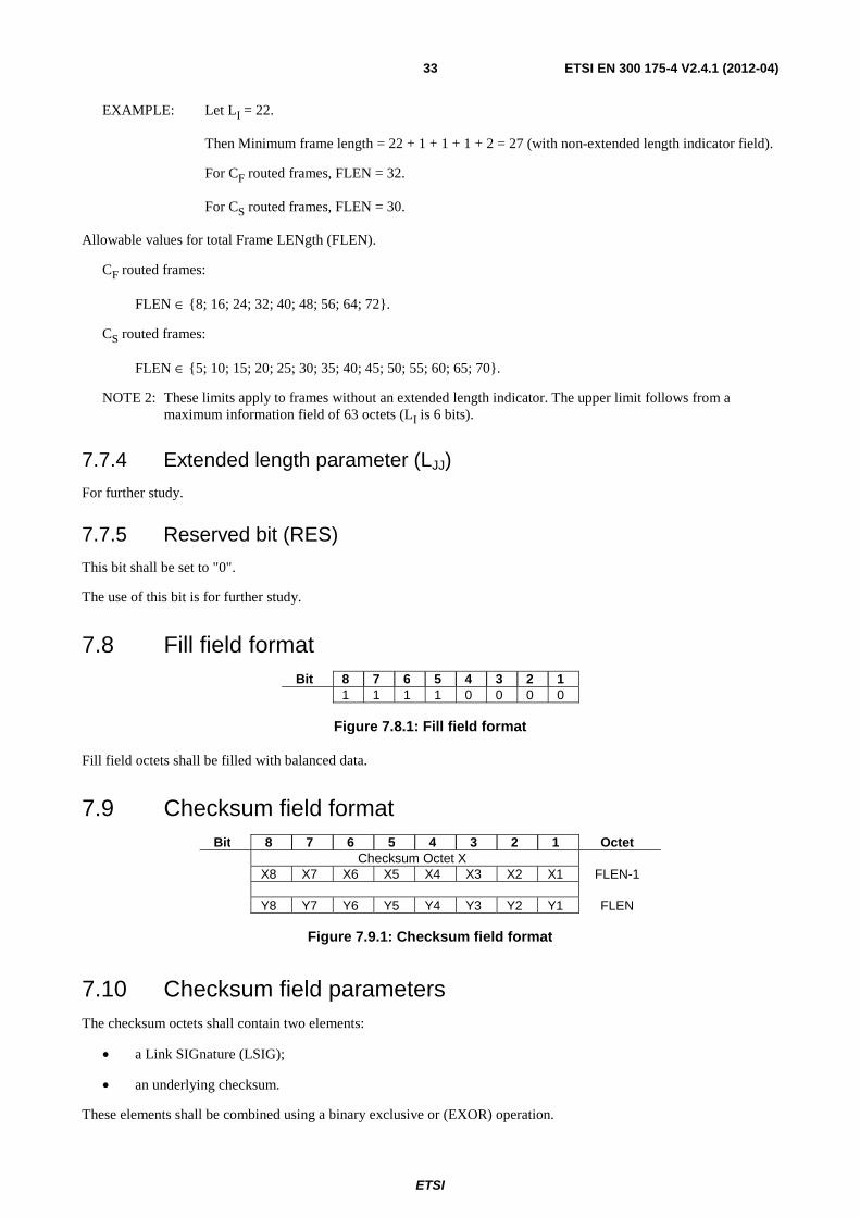
ETSI
ETSI EN 300 175-4 V2.4.1 (2012-04) 33
EXAMPLE: Let LI = 22.
Then Minimum frame length = 22 + 1 + 1 + 1 + 2 = 27 (with non-extended length indicator field).
For CF routed frames, FLEN = 32.
For CS routed frames, FLEN = 30.
Allowable values for total Frame LENgth (FLEN).
CF routed frames:
FLEN ∈ {8; 16; 24; 32; 40; 48; 56; 64; 72}.
CS routed frames:
FLEN ∈ {5; 10; 15; 20; 25; 30; 35; 40; 45; 50; 55; 60; 65; 70}.
NOTE 2: These limits apply to frames without an extended length indicator. The upper limit follows from a maximum information field of 63 octets (LI is 6 bits).
7.7.4 Extended length parameter (LJJ)
For further study.
7.7.5 Reserved bit (RES)
This bit shall be set to "0".
The use of this bit is for further study.
7.8 Fill field format Bit 8 7 6 5 4 3 2 1
1 1 1 1 0 0 0 0
Figure 7.8.1: Fill field format
Fill field octets shall be filled with balanced data.
7.9 Checksum field format Bit 8 7 6 5 4 3 2 1 Octet
Checksum Octet X X8 X7 X6 X5 X4 X3 X2 X1 FLEN-1 Y8 Y7 Y6 Y5 Y4 Y3 Y2 Y1 FLEN
Figure 7.9.1: Checksum field format
7.10 Checksum field parameters The checksum octets shall contain two elements:
• a Link SIGnature (LSIG);
• an underlying checksum.
These elements shall be combined using a binary exclusive or (EXOR) operation.
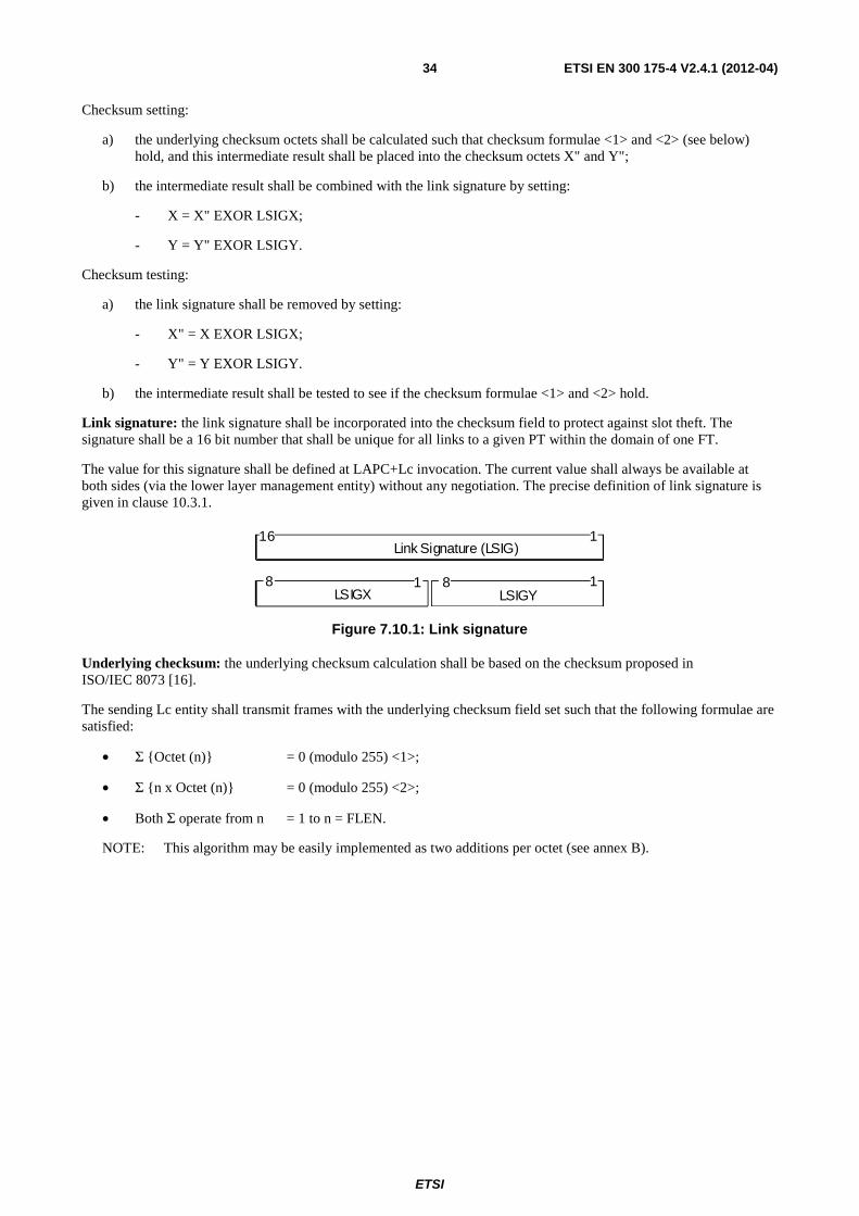
ETSI
ETSI EN 300 175-4 V2.4.1 (2012-04) 34
Checksum setting:
a) the underlying checksum octets shall be calculated such that checksum formulae <1> and <2> (see below) hold, and this intermediate result shall be placed into the checksum octets X" and Y";
b) the intermediate result shall be combined with the link signature by setting:
- X = X" EXOR LSIGX;
- Y = Y" EXOR LSIGY.
Checksum testing:
a) the link signature shall be removed by setting:
- X" = X EXOR LSIGX;
- Y" = Y EXOR LSIGY.
b) the intermediate result shall be tested to see if the checksum formulae <1> and <2> hold.
Link signature: the link signature shall be incorporated into the checksum field to protect against slot theft. The signature shall be a 16 bit number that shall be unique for all links to a given PT within the domain of one FT.
The value for this signature shall be defined at LAPC+Lc invocation. The current value shall always be available at both sides (via the lower layer management entity) without any negotiation. The precise definition of link signature is given in clause 10.3.1.
L i n k S i g n a t u r e ( L S I G ) 1 1 6
L S I G X 8
L S I G Y 8 1 1
Figure 7.10.1: Link signature
Underlying checksum: the underlying checksum calculation shall be based on the checksum proposed in ISO/IEC 8073 [16].
The sending Lc entity shall transmit frames with the underlying checksum field set such that the following formulae are satisfied:
• Σ {Octet (n)} = 0 (modulo 255) <1>;
• Σ {n x Octet (n)} = 0 (modulo 255) <2>;
• Both Σ operate from n = 1 to n = FLEN.
NOTE: This algorithm may be easily implemented as two additions per octet (see annex B).
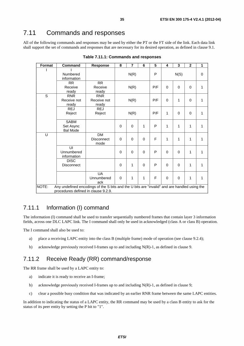
ETSI
ETSI EN 300 175-4 V2.4.1 (2012-04) 35
7.11 Commands and responses All of the following commands and responses may be used by either the PT or the FT side of the link. Each data link shall support the set of commands and responses that are necessary for its desired operation, as defined in clause 9.1.
Table 7.11.1: Commands and responses
Format Command Response 8 7 6 5 4 3 2 1 I I
Numbered information
N(R) P N(S) 0
RR Receive
ready
RR Receive
ready N(R) P/F 0 0 0 1
S RNR Receive not
ready
RNR Receive not
ready N(R) P/F 0 1 0 1
REJ Reject
REJ Reject N(R) P/F 1 0 0 1
SABM Set Async Bal Mode
0 0 1 P 1 1 1 1
U DM Disconnect
mode 0 0 0 F 1 1 1 1
UI Unnumbered information
0 0 0 P 0 0 1 1
DISC Disconnect
0 1 0 P 0 0 1 1
UA Unnumbered
ack 0 1 1 F 0 0 1 1
NOTE: Any undefined encodings of the S bits and the U bits are "invalid" and are handled using the procedures defined in clause 9.2.9.
7.11.1 Information (I) command
The information (I) command shall be used to transfer sequentially numbered frames that contain layer 3 information fields, across one DLC LAPC link. The I command shall only be used in acknowledged (class A or class B) operation.
The I command shall also be used to:
a) place a receiving LAPC entity into the class B (multiple frame) mode of operation (see clause 9.2.4);
b) acknowledge previously received I-frames up to and including N(R)-1, as defined in clause 9.
7.11.2 Receive Ready (RR) command/response
The RR frame shall be used by a LAPC entity to:
a) indicate it is ready to receive an I-frame;
b) acknowledge previously received I-frames up to and including N(R)-1, as defined in clause 9;
c) clear a possible busy condition that was indicated by an earlier RNR frame between the same LAPC entities.
In addition to indicating the status of a LAPC entity, the RR command may be used by a class B entity to ask for the status of its peer entity by setting the P bit to "1".
ETSI
ETSI EN 300 175-4 V2.4.1 (2012-04) 36
7.11.3 Receive Not Ready (RNR) command/response
The RNR frame shall be used by a LAPC entity to:
a) indicate a busy condition, that is, a temporary inability to accept additional I-frames;
b) acknowledge previously received I-frames up to and including N(R)-1, as defined in clause 9.
In addition to indicating the status of a LAPC entity, the RNR command may be used by a class B entity to ask for the status of its peer entity by setting the P bit to "1".
7.11.4 REJect (REJ) command/response
The REJ frame shall be used by a LAPC entity to set an exception condition that requests retransmission of I-frames starting with the frame numbered N(R). The REJ frame shall acknowledge I-frames numbered up to and including N(R)-1. The retransmitted frames shall be transmitted before any new I-frames (I-frames pending initial transmission) are transmitted.
Only one REJ exception condition shall be established at a time for a given direction of information transfer. A REJ exception condition shall be cleared upon receipt of an I-frame with an N(S) equal to the N(R) of the REJ frame.
The transmission of an REJ frame shall also indicate the clearance of any busy condition in the sending LAPC entity that was reported by the earlier transmission of an RNR frame by the same LAPC entity.
In addition to indicating the status of a LAPC entity, the REJ command may be used by a LAPC entity to ask for the status of its peer entity by setting the P bit to "1".
No information field shall be permitted in a REJ frame.
7.11.5 Set Asynchronous Balanced Mode (SABM) command
The SABM command shall be used to re-establish class B multiple frame acknowledged operation.
The receiving LAPC entity shall confirm acceptance of the SABM command by transmitting a UA response at the first opportunity. Upon accepting the SABM command, the entity shall set the variables V(S), V(A), V(R) and the retransmission counter to 0.
Transmission of a SABM command shall indicate the clearance of a busy condition that was reported by the earlier transmission of an RNR frame by that same LAPC entity.
Previously transmitted I-frames that are unacknowledged when the SABM command is performed shall remain unacknowledged, and shall be discarded. It is the responsibility of the higher layer (layer 3) or the management entity to recover from this possible loss of I-frames.
No information field shall be allowed as part of a SABM frame.
7.11.6 Disconnect Mode (DM) response
The DM response shall be used by a LAPC entity to report to its peer entity that it is in a state such that multiple frame re-establishment cannot be performed. A LAPC entity shall transmit a DM response whenever a valid command is received which it cannot action.
No information field shall be permitted in a DM response.
7.11.7 Unnumbered Information (UI) command
The UI command shall be used to transfer unacknowledged (and unnumbered) frames that contain layer 3 information fields, across one DLC LAPC link. A UI-command frame shall only be used if requested by the layer 3 entity, and UI-frames may be lost without notification to the layer 3 entity if a data link exception occurs during the transmission of the frame.
ETSI
ETSI EN 300 175-4 V2.4.1 (2012-04) 37
Only UI-frames shall be used when providing a connectionless service (SAPI = "3") using the procedures defined in clause 9.3.
7.11.8 DISConnect (DISC) command
The DISC command shall be used to terminate class B multiple frame operation.
Prior to performing the command, the LAPC entity receiving the command shall confirm acceptance of the command by transmitting a UA response. The LAPC entity sending the DISC command shall terminate multiple frame operation when it receives the acknowledging UA or DM response.
No information field shall be permitted in a DISC command.
7.11.9 Unnumbered ACK (UA) response
The UA response shall be used by a DLC entity to acknowledge the receipt and acceptance of the mode setting commands (SABM and DISC). These received mode setting commands shall not be performed until the UA response is transmitted.
The transmission of a UA response shall also indicate the clearance of a busy condition that was reported by the earlier transmission of an RNR frame by that same LAPC entity.
No information field shall be permitted in a UA response.
8 Primitives
8.1 Primitive types Four primitive types may be used:
req (request): for a higher layer to request service from a lower layer;
cfm (confirm): for the layer providing the service to confirm that the activity has been completed;
ind (indication): for a layer providing a service to notify the next higher layer of any specific service related activity;
res (response): for a layer to acknowledge receipt of an indication primitive from the next lower layer.
The defined types for each category of primitive are shown as a list in curly brackets.
EXAMPLE: DL_RELEASE -{req, cfm, ind}.
In this example the defined types are request, confirm and indicate (but not response).
NOTE: These primitives are defined only for the purpose of describing layer-to-layer interaction. The primitives are defined as an abstract list of parameters, and their concrete realization may vary between implementations. No formal testing of primitives is intended.
8.2 Primitives to the MAC layer (lower layer) The primitives used for communication to the MAC layer are described in EN 300 175-3 [3].
8.3 Primitives to the NWK layer (higher layer) This clause summarizes the primitives between the DLC layer and the NWK layer together with the list of associated parameters.
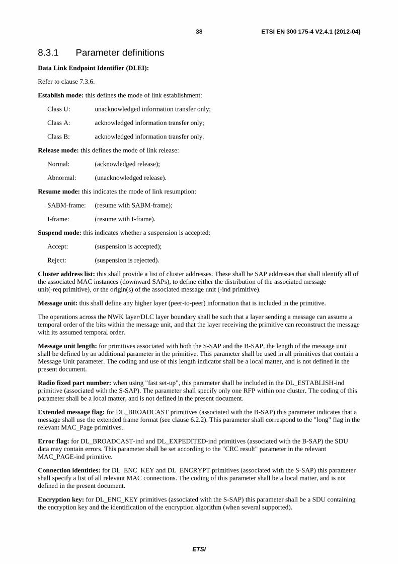
ETSI
ETSI EN 300 175-4 V2.4.1 (2012-04) 38
8.3.1 Parameter definitions
Data Link Endpoint Identifier (DLEI):
Refer to clause 7.3.6.
Establish mode: this defines the mode of link establishment:
Class U: unacknowledged information transfer only;
Class A: acknowledged information transfer only;
Class B: acknowledged information transfer only.
Release mode: this defines the mode of link release:
Normal: (acknowledged release);
Abnormal: (unacknowledged release).
Resume mode: this indicates the mode of link resumption:
SABM-frame: (resume with SABM-frame);
I-frame: (resume with I-frame).
Suspend mode: this indicates whether a suspension is accepted:
Accept: (suspension is accepted);
Reject: (suspension is rejected).
Cluster address list: this shall provide a list of cluster addresses. These shall be SAP addresses that shall identify all of the associated MAC instances (downward SAPs), to define either the distribution of the associated message unit(-req primitive), or the origin(s) of the associated message unit (-ind primitive).
Message unit: this shall define any higher layer (peer-to-peer) information that is included in the primitive.
The operations across the NWK layer/DLC layer boundary shall be such that a layer sending a message can assume a temporal order of the bits within the message unit, and that the layer receiving the primitive can reconstruct the message with its assumed temporal order.
Message unit length: for primitives associated with both the S-SAP and the B-SAP, the length of the message unit shall be defined by an additional parameter in the primitive. This parameter shall be used in all primitives that contain a Message Unit parameter. The coding and use of this length indicator shall be a local matter, and is not defined in the present document.
Radio fixed part number: when using "fast set-up", this parameter shall be included in the DL_ESTABLISH-ind primitive (associated with the S-SAP). The parameter shall specify only one RFP within one cluster. The coding of this parameter shall be a local matter, and is not defined in the present document.
Extended message flag: for DL_BROADCAST primitives (associated with the B-SAP) this parameter indicates that a message shall use the extended frame format (see clause 6.2.2). This parameter shall correspond to the "long" flag in the relevant MAC_Page primitives.
Error flag: for DL_BROADCAST-ind and DL_EXPEDITED-ind primitives (associated with the B-SAP) the SDU data may contain errors. This parameter shall be set according to the "CRC result" parameter in the relevant MAC_PAGE-ind primitive.
Connection identities: for DL_ENC_KEY and DL_ENCRYPT primitives (associated with the S-SAP) this parameter shall specify a list of all relevant MAC connections. The coding of this parameter shall be a local matter, and is not defined in the present document.
Encryption key: for DL_ENC_KEY primitives (associated with the S-SAP) this parameter shall be a SDU containing the encryption key and the identification of the encryption algorithm (when several supported).
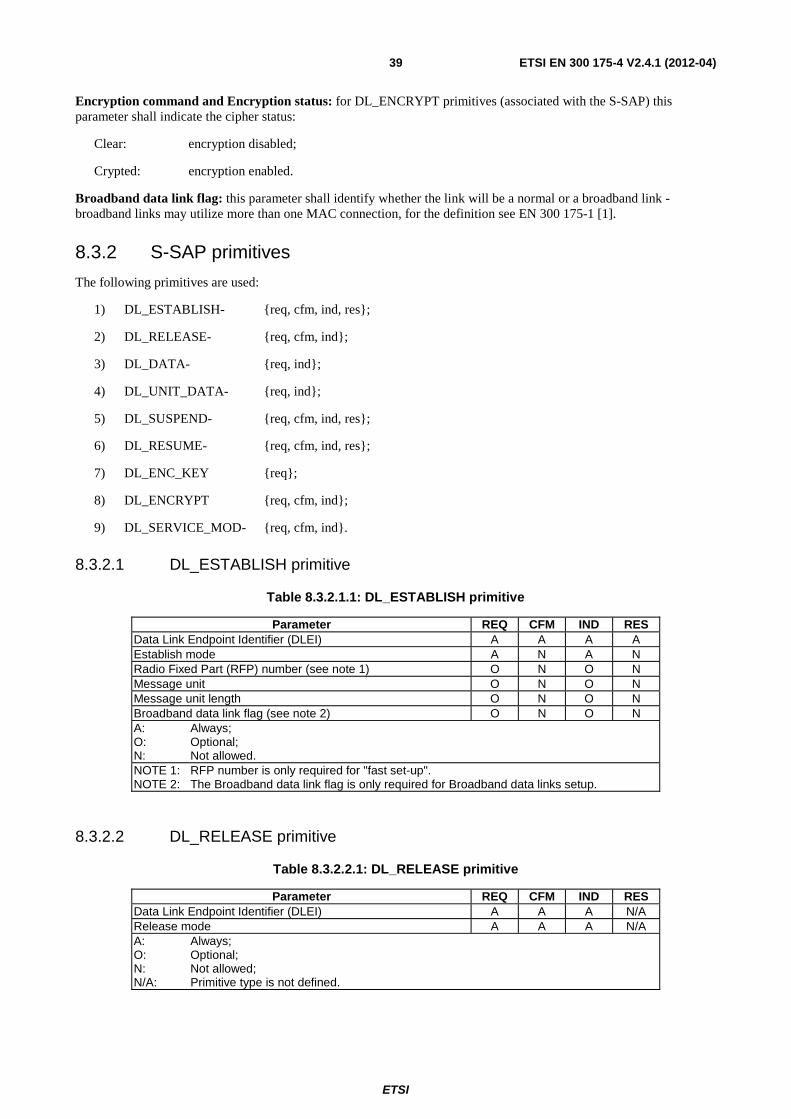
ETSI
ETSI EN 300 175-4 V2.4.1 (2012-04) 39
Encryption command and Encryption status: for DL_ENCRYPT primitives (associated with the S-SAP) this parameter shall indicate the cipher status:
Clear: encryption disabled;
Crypted: encryption enabled.
Broadband data link flag: this parameter shall identify whether the link will be a normal or a broadband link - broadband links may utilize more than one MAC connection, for the definition see EN 300 175-1 [1].
8.3.2 S-SAP primitives
The following primitives are used:
1) DL_ESTABLISH- {req, cfm, ind, res};
2) DL_RELEASE- {req, cfm, ind};
3) DL_DATA- {req, ind};
4) DL_UNIT_DATA- {req, ind};
5) DL_SUSPEND- {req, cfm, ind, res};
6) DL_RESUME- {req, cfm, ind, res};
7) DL_ENC_KEY {req};
8) DL_ENCRYPT {req, cfm, ind};
9) DL_SERVICE_MOD- {req, cfm, ind}.
8.3.2.1 DL_ESTABLISH primitive
Table 8.3.2.1.1: DL_ESTABLISH primitive
Parameter REQ CFM IND RES Data Link Endpoint Identifier (DLEI) A A A A Establish mode A N A N Radio Fixed Part (RFP) number (see note 1) O N O N Message unit O N O N Message unit length O N O N Broadband data link flag (see note 2) O N O N A: Always; O: Optional; N: Not allowed. NOTE 1: RFP number is only required for "fast set-up". NOTE 2: The Broadband data link flag is only required for Broadband data links setup.
8.3.2.2 DL_RELEASE primitive
Table 8.3.2.2.1: DL_RELEASE primitive
Parameter REQ CFM IND RES Data Link Endpoint Identifier (DLEI) A A A N/A Release mode A A A N/A A: Always; O: Optional; N: Not allowed; N/A: Primitive type is not defined.
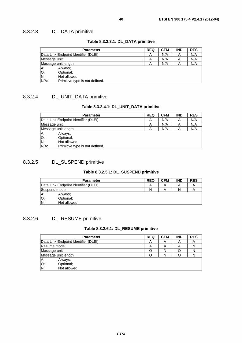
ETSI
ETSI EN 300 175-4 V2.4.1 (2012-04) 40
8.3.2.3 DL_DATA primitive
Table 8.3.2.3.1: DL_DATA primitive
Parameter REQ CFM IND RES Data Link Endpoint Identifier (DLEI) A N/A A N/A Message unit A N/A A N/A Message unit length A N/A A N/A A: Always; O: Optional; N: Not allowed; N/A: Primitive type is not defined.
8.3.2.4 DL_UNIT_DATA primitive
Table 8.3.2.4.1: DL_UNIT_DATA primitive
Parameter REQ CFM IND RES Data Link Endpoint Identifier (DLEI) A N/A A N/A Message unit A N/A A N/A Message unit length A N/A A N/A A: Always; O: Optional; N: Not allowed; N/A: Primitive type is not defined.
8.3.2.5 DL_SUSPEND primitive
Table 8.3.2.5.1: DL_SUSPEND primitive
Parameter REQ CFM IND RES Data Link Endpoint Identifier (DLEI) A A A A Suspend mode N A N A A: Always; O: Optional; N: Not allowed.
8.3.2.6 DL_RESUME primitive
Table 8.3.2.6.1: DL_RESUME primitive
Parameter REQ CFM IND RES Data Link Endpoint Identifier (DLEI) A A A A Resume mode A A A N Message unit O N O N Message unit length O N O N A: Always; O: Optional; N: Not allowed.
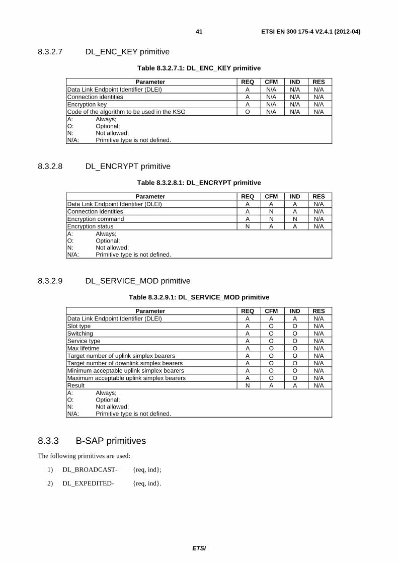
ETSI
ETSI EN 300 175-4 V2.4.1 (2012-04) 41
8.3.2.7 DL_ENC_KEY primitive
Table 8.3.2.7.1: DL_ENC_KEY primitive
Parameter REQ CFM IND RES Data Link Endpoint Identifier (DLEI) A N/A N/A N/A Connection identities A N/A N/A N/A Encryption key A N/A N/A N/A Code of the algorithm to be used in the KSG O N/A N/A N/A A: Always; O: Optional; N: Not allowed; N/A: Primitive type is not defined.
8.3.2.8 DL_ENCRYPT primitive
Table 8.3.2.8.1: DL_ENCRYPT primitive
Parameter REQ CFM IND RES Data Link Endpoint Identifier (DLEI) A A A N/A Connection identities A N A N/A Encryption command A N N N/A Encryption status N A A N/A A: Always; O: Optional; N: Not allowed; N/A: Primitive type is not defined.
8.3.2.9 DL_SERVICE_MOD primitive
Table 8.3.2.9.1: DL_SERVICE_MOD primitive
Parameter REQ CFM IND RES Data Link Endpoint Identifier (DLEI) A A A N/A Slot type A O O N/A Switching A O O N/A Service type A O O N/A Max lifetime A O O N/A Target number of uplink simplex bearers A O O N/A Target number of downlink simplex bearers A O O N/A Minimum acceptable uplink simplex bearers A O O N/A Maximum acceptable uplink simplex bearers A O O N/A Result N A A N/A A: Always; O: Optional; N: Not allowed; N/A: Primitive type is not defined.
8.3.3 B-SAP primitives
The following primitives are used:
1) DL_BROADCAST- {req, ind};
2) DL_EXPEDITED- {req, ind}.
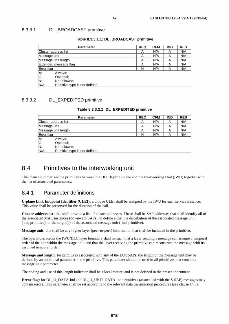
ETSI
ETSI EN 300 175-4 V2.4.1 (2012-04) 42
8.3.3.1 DL_BROADCAST primitive
Table 8.3.3.1.1: DL_BROADCAST primitive
Parameter REQ CFM IND RES Cluster address list A N/A A N/A Message unit A N/A A N/A Message unit length A N/A A N/A Extended message flag A N/A A N/A Error flag N N/A A N/A A: Always; O: Optional; N: Not allowed; N/A: Primitive type is not defined.
8.3.3.2 DL_EXPEDITED primitive
Table 8.3.3.2.1: DL_EXPEDITED primitive
Parameter REQ CFM IND RES Cluster address list A N/A A N/A Message unit A N/A A N/A Message unit length A N/A A N/A Error flag N N/A A N/A A: Always; O: Optional; N: Not allowed; N/A: Primitive type is not defined.
8.4 Primitives to the interworking unit This clause summarizes the primitives between the DLC layer U-plane and the Interworking Unit (IWU) together with the list of associated parameters.
8.4.1 Parameter definitions
U-plane Link Endpoint Identifier (ULEI): a unique ULEI shall be assigned by the IWU for each service instance. This value shall be preserved for the duration of the call.
Cluster address list: this shall provide a list of cluster addresses. These shall be SAP addresses that shall identify all of the associated MAC instances (downward SAPs), to define either the distribution of the associated message unit (-req primitive), or the origin(s) of the associated message unit (-ind primitive).
Message unit: this shall be any higher layer (peer-to-peer) information that shall be included in the primitive.
The operations across the IWU/DLC layer boundary shall be such that a layer sending a message can assume a temporal order of the bits within the message unit, and that the layer receiving the primitive can reconstruct the message with its assumed temporal order.
Message unit length: for primitives associated with any of the LUx SAPs, the length of the message unit may be defined by an additional parameter in the primitive. This parameter should be used in all primitives that contain a message unit parameter.
The coding and use of this length indicator shall be a local matter, and is not defined in the present document.
Error flag: for DL_U_DATA-ind and DL_U_UNIT-DATA-ind primitives (associated with the S-SAP) messages may contain errors. This parameter shall be set according to the relevant data transmission procedures (see clause 14.3).
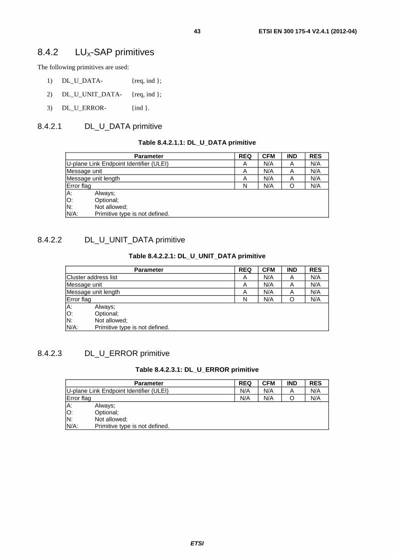
ETSI
ETSI EN 300 175-4 V2.4.1 (2012-04) 43
8.4.2 LUX-SAP primitives
The following primitives are used:
1) DL_U_DATA- {req, ind };
2) DL_U_UNIT_DATA- {req, ind };
3) DL_U_ERROR- {ind }.
8.4.2.1 DL_U_DATA primitive
Table 8.4.2.1.1: DL_U_DATA primitive
Parameter REQ CFM IND RES U-plane Link Endpoint Identifier (ULEI) A N/A A N/A Message unit A N/A A N/A Message unit length A N/A A N/A Error flag N N/A O N/A A: Always; O: Optional; N: Not allowed; N/A: Primitive type is not defined.
8.4.2.2 DL_U_UNIT_DATA primitive
Table 8.4.2.2.1: DL_U_UNIT_DATA primitive
Parameter REQ CFM IND RES Cluster address list A N/A A N/A Message unit A N/A A N/A Message unit length A N/A A N/A Error flag N N/A O N/A A: Always; O: Optional; N: Not allowed; N/A: Primitive type is not defined.
8.4.2.3 DL_U_ERROR primitive
Table 8.4.2.3.1: DL_U_ERROR primitive
Parameter REQ CFM IND RES U-plane Link Endpoint Identifier (ULEI) N/A N/A A N/A Error flag N/A N/A O N/A A: Always; O: Optional; N: Not allowed; N/A: Primitive type is not defined.
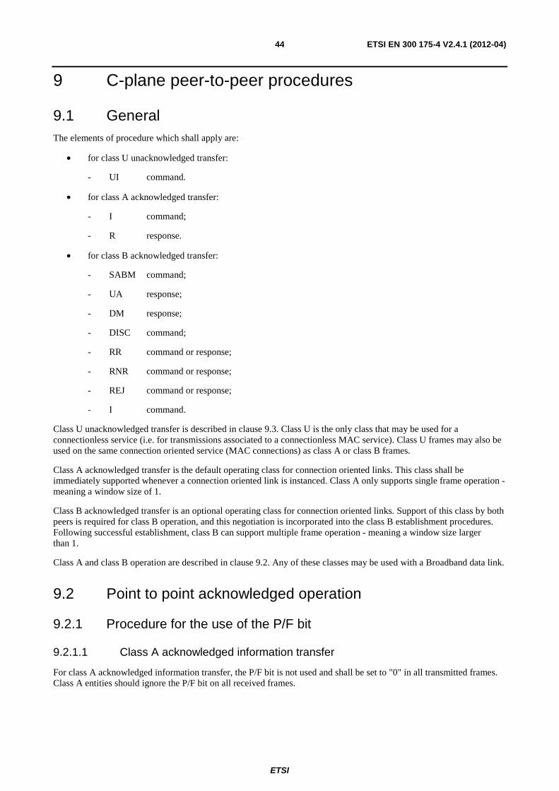
ETSI
ETSI EN 300 175-4 V2.4.1 (2012-04) 44
9 C-plane peer-to-peer procedures
9.1 General The elements of procedure which shall apply are:
• for class U unacknowledged transfer:
- UI command.
• for class A acknowledged transfer:
- I command;
- R response.
• for class B acknowledged transfer:
- SABM command;
- UA response;
- DM response;
- DISC command;
- RR command or response;
- RNR command or response;
- REJ command or response;
- I command.
Class U unacknowledged transfer is described in clause 9.3. Class U is the only class that may be used for a connectionless service (i.e. for transmissions associated to a connectionless MAC service). Class U frames may also be used on the same connection oriented service (MAC connections) as class A or class B frames.
Class A acknowledged transfer is the default operating class for connection oriented links. This class shall be immediately supported whenever a connection oriented link is instanced. Class A only supports single frame operation - meaning a window size of 1.
Class B acknowledged transfer is an optional operating class for connection oriented links. Support of this class by both peers is required for class B operation, and this negotiation is incorporated into the class B establishment procedures. Following successful establishment, class B can support multiple frame operation - meaning a window size larger than 1.
Class A and class B operation are described in clause 9.2. Any of these classes may be used with a Broadband data link.
9.2 Point to point acknowledged operation
9.2.1 Procedure for the use of the P/F bit
9.2.1.1 Class A acknowledged information transfer
For class A acknowledged information transfer, the P/F bit is not used and shall be set to "0" in all transmitted frames. Class A entities should ignore the P/F bit on all received frames.
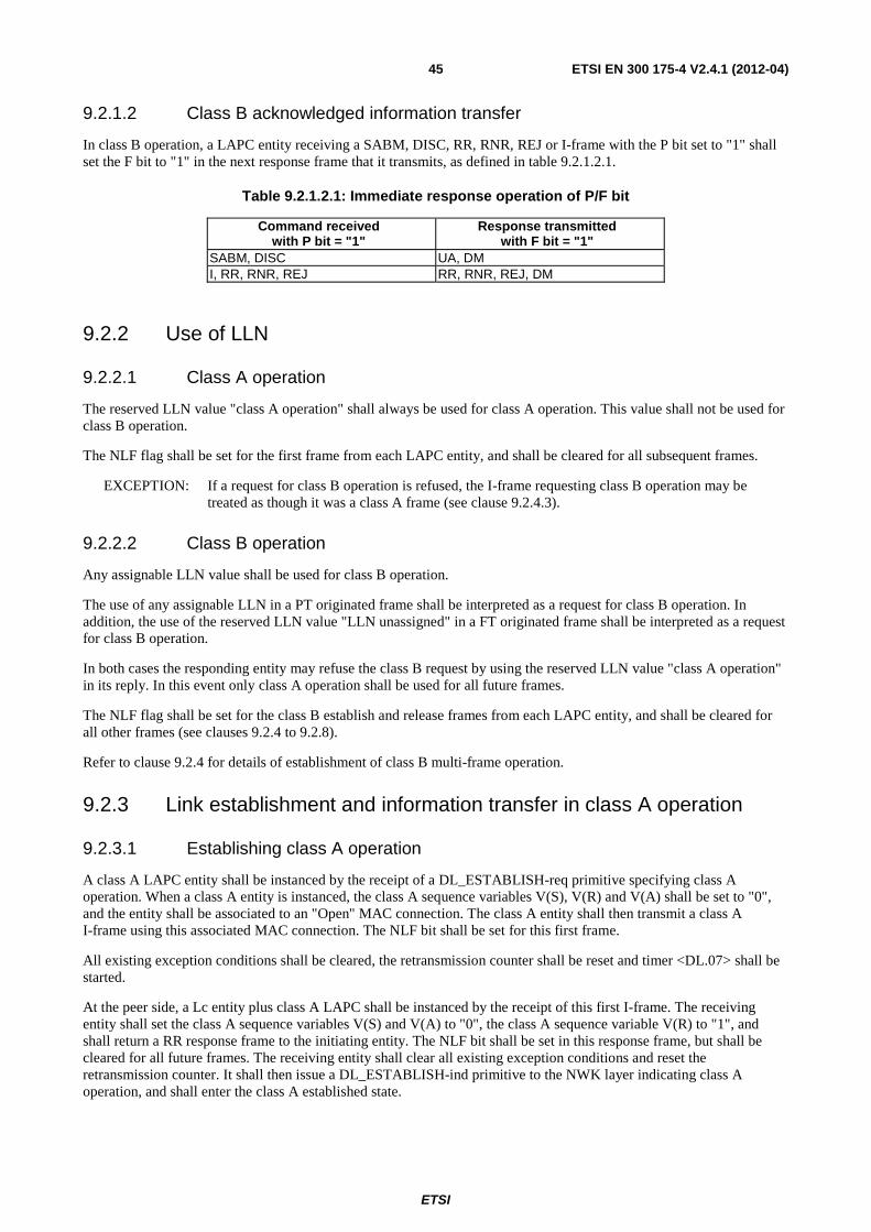
ETSI
ETSI EN 300 175-4 V2.4.1 (2012-04) 45
9.2.1.2 Class B acknowledged information transfer
In class B operation, a LAPC entity receiving a SABM, DISC, RR, RNR, REJ or I-frame with the P bit set to "1" shall set the F bit to "1" in the next response frame that it transmits, as defined in table 9.2.1.2.1.
Table 9.2.1.2.1: Immediate response operation of P/F bit
Command received with P bit = "1"
Response transmitted with F bit = "1"
SABM, DISC UA, DM I, RR, RNR, REJ RR, RNR, REJ, DM
9.2.2 Use of LLN
9.2.2.1 Class A operation
The reserved LLN value "class A operation" shall always be used for class A operation. This value shall not be used for class B operation.
The NLF flag shall be set for the first frame from each LAPC entity, and shall be cleared for all subsequent frames.
EXCEPTION: If a request for class B operation is refused, the I-frame requesting class B operation may be treated as though it was a class A frame (see clause 9.2.4.3).
9.2.2.2 Class B operation
Any assignable LLN value shall be used for class B operation.
The use of any assignable LLN in a PT originated frame shall be interpreted as a request for class B operation. In addition, the use of the reserved LLN value "LLN unassigned" in a FT originated frame shall be interpreted as a request for class B operation.
In both cases the responding entity may refuse the class B request by using the reserved LLN value "class A operation" in its reply. In this event only class A operation shall be used for all future frames.
The NLF flag shall be set for the class B establish and release frames from each LAPC entity, and shall be cleared for all other frames (see clauses 9.2.4 to 9.2.8).
Refer to clause 9.2.4 for details of establishment of class B multi-frame operation.
9.2.3 Link establishment and information transfer in class A operation
9.2.3.1 Establishing class A operation
A class A LAPC entity shall be instanced by the receipt of a DL_ESTABLISH-req primitive specifying class A operation. When a class A entity is instanced, the class A sequence variables V(S), V(R) and V(A) shall be set to "0", and the entity shall be associated to an "Open" MAC connection. The class A entity shall then transmit a class A I-frame using this associated MAC connection. The NLF bit shall be set for this first frame.
All existing exception conditions shall be cleared, the retransmission counter shall be reset and timer <DL.07> shall be started.
At the peer side, a Lc entity plus class A LAPC shall be instanced by the receipt of this first I-frame. The receiving entity shall set the class A sequence variables V(S) and V(A) to "0", the class A sequence variable V(R) to "1", and shall return a RR response frame to the initiating entity. The NLF bit shall be set in this response frame, but shall be cleared for all future frames. The receiving entity shall clear all existing exception conditions and reset the retransmission counter. It shall then issue a DL_ESTABLISH-ind primitive to the NWK layer indicating class A operation, and shall enter the class A established state.
ETSI
ETSI EN 300 175-4 V2.4.1 (2012-04) 46
Upon receipt of the RR response frame with the NLF bit set the initiating entity shall stop timer <DL.07>, shall issue a DL_ESTABLISH-cfm primitive to the NWK layer, and shall mark the link as established. The NLF bit shall be cleared for all future frames.
NOTE 1: Usually a new MAC connection will have to be opened. In this case, the DL_ESTABLISH-cfm reports on a successful opening as well as successful link establishment.
If timer <DL.07> expires before a RR response with the NLF bit set to "1" is received, the LAPC entity shall:
a) if the value of the retransmission counter is less than N250:
- retransmit the I command as above;
- add one to the retransmission counter;
- restart timer <DL.07>.
b) if the value of the retransmission counter is equal to N250:
- report establishment failure to the NWK layer with a DL_RELEASE-ind primitive. It shall then discard all relevant DL_DATA-req primitives and all outstanding I-frames, and remain in the ULI state.
NOTE 2: A class A entity should be instanced by the failure of class B establishment, provided that a class A entity does not already exist (see clause 9.2.4).
9.2.3.2 Class A acknowledged information transfer
Class A information transfer is similar to class B, but it is restricted to the use of a fixed window size of 1 and the modulus is set to 2.
Acknowledged information is passed to the DLC layer by the NWK layer using the DL_DATA-req primitive. The complete message unit of this primitive shall be segmented (if necessary) and the segments shall be sequentially transmitted in a series of one or more I-frames.
At the destination LAPC entity, a complete message shall be reassembled from this series of I-frames, and when complete it shall be delivered to the NWK layer in a DL_DATA-ind primitive.
The procedures which apply to the transmission and reception of each I-frame are defined below (see clauses 9.2.3.3 and 9.2.3.4).
NOTE: The term "transmission of an I-frame" refers to the delivery of a complete I-frame to the MAC layer. The term "reception of an I-frame" refers to the receipt of a complete I-frame from the MAC layer.
In the case of Broadband data link, after the data link has been established (including the first connection) and resource negotiation has taken place (in the NWK layer) multiple MAC connections may be associated with the data link. Reception and/or transmission of LAPC+Lc data (frames) can occur on any of those connections.
9.2.3.3 Transmission of class A I-frames
For each I-frame, the control field parameters N(S) and N(R) shall be assigned the values of V(S) and V(R) respectively. V(S) shall be incremented by 1 at the end of the transmission of the I-frame.
Timer <DL.04> shall be started at the time of transmission of each I-frame. If timer <DL.04> expires, the procedures defined in clause 9.2.3.6 shall be followed.
A subsequent I-frame shall only be transmitted when a positive acknowledgement has been received for the previous I-frame. This acknowledgement can be contained in the receive sequence number N(R) of either a RR response frame, or an I-command frame.
Any DL_DATA-req primitives received whilst in the timer-retransmit condition shall be queued.
ETSI
ETSI EN 300 175-4 V2.4.1 (2012-04) 47
9.2.3.4 Reception of class A I-frames
Independent of a timer-retransmit condition, when a LAPC entity is not in an own receiver busy condition and receives a valid I-frame it shall proceed as follows:
a) If the N(S) of the I-frame is equal to the current V(R), the LAPC entity shall:
- append the information field of the frame to any existing unfinished message (segment reassemble);
- if the more data bit value is "0" (indicating that this is the last segment of the message) it shall pass the complete message to the NWK layer using the DL_DATA-ind primitive;
- increment by 1 its V(R) and send an immediate acknowledgement using either a RR response frame or I-command frame containing an updated receive sequence number, N(R) = V(R).
b) If the N(S) of the I-frame is not equal to the current V(R), the LAPC entity shall:
- send an immediate acknowledgement using either a RR response frame or I-command frame containing the current value (not updated) of receive sequence number, N(R).
NOTE: Only one value of LLN is valid for class A operation. The receiving entity may also have one or more assigned LLNs (i.e. it may have concurrent class B operation).
Any invalid class A I-frame shall be discarded, and no further action shall be taken.
9.2.3.5 Receiving acknowledgements
On receipt of a valid I-frame or RR response frame, the LAPC entity shall treat the N(R) contained in this frame as an acknowledgement for the I-frame containing the N(S) value of N(R)-1. It shall proceed according to the N(R) value as follows:
a) if the N(R) value corresponds to the expected value (i.e. N(R) = N(S) + 1, where N(S) is the most recently sent value of N(S)) the LAPC entity shall set V(A) equal to N(R), and shall reset timer <DL.04>;
b) if the N(R) value does not correspond to the expected value, but is in the range V(A) ≤ N(R) ≤ V(S), V(A) shall not be updated. Timer <DL.04> shall continue to run;
c) if the N(R) value is invalid, the LAPC entity shall immediately initiate a link re-establishment using the normal link establishment procedures defined in clause 9.2.3.1 or release the connection.
NOTE 1: In the event of a lost or erroneous acknowledgement, retransmission only occurs when timer <DL.04> expires as described in clause 9.2.3.6.
NOTE 2: Case b) should only occur if I-frames cross in transit; it does not indicate a transmission error. For example, a lost, errored or erroneous I-frame should generate no peer response, and a lost, errored or erroneous acknowledgement will generate an (unwanted) retransmission followed by case a) acknowledge. Therefore, case b) may be used to indicate proper connection operation, but will not generate any (re)transmission actions.
9.2.3.6 Waiting for acknowledgement
The LAPC entity shall maintain an internal retransmission count variable. If timer <DL.04> expires, the LAPC entity shall:
• if it is not yet in the timer-retransmit condition, enter the timer-retransmit condition and reset the retransmission count variable; or
• if it is already in the timer-retransmit condition, add one to its retransmission count variable.
ETSI
ETSI EN 300 175-4 V2.4.1 (2012-04) 48
The LAPC entity shall then:
• if the value of the retransmission count variable is less than N250, restart timer <DL.04>; and retransmit the last transmitted I-frame (V(S)-1); or
• if the value of the retransmission count variable is equal to N250, release the link, by issuing a MAC_DIS-req primitive to the MAC layer, and shall report this release to the NWK layer using a DL_RELEASE-ind primitive, with the "release mode" parameter set to "abnormal".
The timer-retransmit condition is cleared when the LAPC entity receives a valid RR response frame or I-command frame containing the expected value of N(R). It shall then set its V(A) to the value of the received N(R). Timer <DL.04> shall be reset, and then the LAPC entity shall resume with I-frame transmission.
9.2.3.7 Release of class A operation
Release of class A operation, involves the release of all the LAPC resources. The following procedure only applies if the LAPC entity is in the ULI state.
The class A release process is initiated by a DL_RELEASE-req primitive from the NWK layer.
If this primitive indicates the release mode as "normal" the LAPC entity shall attempt to complete transmission of all outstanding I-frames and of all outstanding DL_DATA-req primitives before releasing the link. The LAPC shall only initiate link release as described in the following clauses if all of this outstanding data has been successfully acknowledged.
If there is no outstanding data, or if the DL_RELEASE-req primitive indicates "abnormal" release mode, the LAPC shall initiate an immediate link release. In this event, the LAPC entity shall return a DL_RELEASE-cfm primitive to the NWK layer, and shall then cease operation. All further frames shall be ignored and any outstanding DL_DATA-req primitives and all outstanding I-frames shall be discarded. The DL_RELEASE-cfm primitive shall indicate "normal" release mode only if there was no outstanding data. If any DL_DATA-req or I-frames are discarded or are unacknowledged, the DL_RELEASE-cfm primitive shall indicate "abnormal" release mode.
Following a release of the link, and if no other links are using the associated MAC connection, the LLME shall immediately release that connection as described in clause 10.2.2.
The peer DLC entity, upon receiving an upward release as a result of this release procedure, shall proceed according to the procedures defined in clause 9.2.7.
9.2.3.8 Re-establishment of class A operation
A class A link may be re-established at any time using the normal link establishment procedures defined in clause 9.2.3.1. All outstanding DL_DATA primitives and I-frames shall be discarded, and all link variables shall be reset.
9.2.4 Establishing class B multiple frame operation
9.2.4.1 Overview
Only one FT initiated class B establishment procedure shall be active to one specific PT at any one time.
This clause describes the C-plane establishment procedures, whereby a single point-to-point LAPC link suitable for class B multiple frame operation is established between two peer entities.
NOTE: Refer to clause 10.4 for details of U-plane installation and establishment procedures.
During establishment of class B multiple frame operation, the maximum number of outstanding I-frames (the window size) shall be set to "1" for both directions. Once in the ASM state, the maximum number of outstanding I-frames shall be set to the class B value given in clause 7.5.2.2.
The establishment of class B multiple frame operation shall always include assignment of a valid LLN, and this assignment shall be made by the PT in all cases.
ETSI
ETSI EN 300 175-4 V2.4.1 (2012-04) 49
All NWK layer initiated establishment procedures also imply the discarding of all outstanding DL_DATA-req primitives and all queued I-frames.
A subsequent class B re-establishment procedure is allowed at any time using a SABM frame that contains an assigned LLN and with the NLF bit set. Successful re-establishment causes the sequence numbers to be re-initialized at both ends. This procedure is described in clause 9.2.8.
9.2.4.2 Class B multiple frame establishment procedures
Normal establishment is initiated by a LAPC entity, upon receipt of a DL_ESTABLISH-req primitive from the NWK layer requesting class B operation. This primitive shall define the DLEI to be used. The primitive may optionally contain a message unit containing higher layer information.
The LAPC entity shall initiate a request for class B multiple frame operation by setting the sequence variables V(S), V(R) and V(A) to "0" and transmitting an I-command frame, with the P bit set to "1".
All existing exception conditions shall be cleared, the retransmission counter shall be reset and timer <DL.02> shall be started.
If the responding LAPC entity is able to accept the request, it shall respond to the receipt of the I-frame by issuing a DL_ESTABLISH-ind primitive to the NWK layer indicating class B operation. Upon receipt of a DL_ESTABLISH-res primitive containing the same DLEI, it shall:
• set the sequence variables V(S) and V(A) to "0";
• set the sequence variable V(R) to "1"; and
• transmit a RR response frame with the F bit set to the same binary value as the P bit in the I-frame, using a class B accept value of LLN as defined in clause 9.2.4.3.
It shall clear all existing exception conditions, and the retransmission counter shall be reset. It shall then enter the "ASM" state.
If the responding LAPC entity is unable to accept the request for class B operation, it shall respond to the receipt of the I-frame by transmitting a RR response frame with the F bit set to the fixed class A value (see clause 9.2.1.1) and using the appropriate class B reject value of LLN as defined in clause 9.2.4.3.
If a class A link does not already exist, a rejection of class B operation shall instance a class A LAPC entity. In this event, the LAPC entity shall remain in the "ULI" state and shall inform the NWK layer by issuing a DL_ESTABLISH-ind primitive to the NWK layer indicating class A operation.
If a class A link already exists, a rejection of class B operation shall cause no further action.
NOTE: When refusing class B operation and defaulting to class A operation, the responding entity may accept the I-frame according to the class A procedures (see clause 9.2.3.4). This optional procedure is described in clause 9.2.4.3.
Upon receipt of the RR response with the F bit set to "1" and containing a class B accepting value of LLN, the originator of the I command shall:
• reset timer <DL.02>;
• enter the "ASM" state;
• inform the NWK layer using a DL_ESTABLISH-cfm primitive, indicating class B operation.
Upon receipt of a RR response with a rejecting value of LLN, the originator of the I command shall:
• reset timer <DL.02>;
• remain in the "ULI" state;
• retransmit the I-frame if necessary (see clause 9.2.4.3);
ETSI
ETSI EN 300 175-4 V2.4.1 (2012-04) 50
• if defaulting to class A operation, it shall inform the NWK layer using a DL_ESTABLISH-cfm primitive, indicating class A operation;
• if not defaulting to class A operation, it shall inform the NWK layer using a DL_RELEASE-ind primitive, indicating "normal" release of class B operation.
When class B operation is refused and is defaulted to class A operation, the requesting I-frame should be accepted as though it was a class A frame. This default operation should occur if a class A link does not already exist between the PT and the FT (i.e. provided that no previous class A I-frames have been transmitted). In all cases, the NLF bit shall indicate if the initial I-frame has been accepted as though it was a class A frame:
• the NLF bit shall be set if the frame is accepted;
• the NLF bit shall be cleared if the frame is not accepted.
If class B operation is refused, and if the I-frame is not accepted by the receiving entity, the I-frame shall be submitted to the class A transmission queue.
An RR response with the F bit set to "0" shall be ignored.
A DL_RELEASE-req primitive that is received during this establishment procedure shall be queued, and shall be serviced immediately on completion of the establishment procedure.
If timer <DL.02> expires before a RR response with the F bit set to "1" is received, the LAPC entity shall:
a) if the value of the retransmission counter is less than N250:
- retransmit the I command as above;
- add one to the retransmission counter;
- restart timer <DL.02>.
b) if the value of the retransmission counter is equal to N250:
- report establishment failure to the NWK layer with a DL_RELEASE-ind primitive. It shall then discard all relevant DL_DATA-req primitives and all outstanding I-frames, and remain in the ULI state.
9.2.4.3 Class B LLN assignment procedures
Class B assignable values of LLN are always chosen by the PT. In all cases this PT choice of LLN defines a new assignment for that value of LLN. If the FT has existing records of an LLN (e.g. from a previously suspended link) the new assignment shall completely replace the old record.
9.2.4.3.1 PT establishment
For PT initiated establishment, a chosen value of assignable LLN shall be contained in the first I-frame. The NLF bit is set in this first frame to identify a new link establishment.
The responding FT entity shall reply as follows:
a) if it wishes to accept the class B establishment, the RR response shall also use the chosen assignable value of LLN. The NLF bit shall be set in this accepting RR frame;
b) if it wishes to refuse the class B establishment and is defaulting to class A operation, the RR response shall use the reserved LLN value "class A operation";
c) if it wishes to refuse the class B establishment and is unable to default to class A operation the RR response shall use the reserved LLN value "LLN unassigned".
If class B establishment is accepted, the chosen value of LLN shall be used for all subsequent class B frames on this link. The NLF bit shall be clear in all subsequent frames (except for "link release" frames).
Following a refusal of class B operation, the PT may either proceed to operate in class A, or may release the link using the class A release procedures defined in clause 9.2.3.7.
ETSI
ETSI EN 300 175-4 V2.4.1 (2012-04) 51
9.2.4.3.2 FT establishment
For FT initiated establishment, the first I-frame shall use the reserved LLN value "LLN unassigned". The NLF bit is set in this first frame, to indicate a new link establishment.
The responding PT entity shall reply as follows:
a) if it wishes to accept the class B establishment, the RR response shall use a valid assignable LLN value. The NLF bit shall be set in this frame;
b) if it wishes to refuse the class B establishment and is defaulting to class A operation, the RR response shall use the reserved LLN value "class A operation";
c) if it wishes to refuse the class B establishment and is unable to default to class A operation the RR response shall use the reserved LLN value "LLN unassigned".
If class B is establishment is accepted, the chosen value of LLN shall then be used for all subsequent class B frames on this link. The NLF bit shall be clear in all subsequent frames (except for "link release" frames).
Following a refusal of class B operation, the FT may either proceed to operate in class A, or may release the link using the class A release procedures defined in clause 9.2.3.7.
9.2.5 Link maintenance and information transfer in class B multiple frame operation
When a LAPC entity has entered the ASM state, as a result of successful class B establishment, I-frames and S-frames may be transmitted according to the procedures described in this clause.
NOTE 1: If a class B link re-establishment occurs, this may cause duplication or loss of layer 3 messages, since the procedure ignores the possible existence of unacknowledged I-frames.
Information received by the LAPC entity from layer 3 by means of DL_DATA-req primitive shall be segmented (if necessary) and the resulting segments shall be transmitted in a series of one or more I-frames.
At the destination LAPC entity, a complete message shall be reassembled from a series of received I-frames, and the complete message shall be delivered to the NWK layer in DL_DATA-ind primitive.
The procedures which apply to the transmission and reception of each I-frame are defined below.
NOTE 2: The term "transmission of an I-frame" refers to the delivery of a complete I-frame to the MAC layer. The term "reception of an I-frame" refers to the receipt of an I-frame by the LAPC from the MAC layer.
In the case of Broadband data link, after the data link has been established (including the first connection) and resource negotiation has taken place (in the NWK layer) multiple MAC connections may be associated with the data link. Reception and/or transmission of LAPC+Lc data (frames) can occur on any of those connections.
9.2.5.1 Transmitting I-frames
For each I-frame, the control field parameters N(S) and N(R) shall be assigned the values of V(S) and V(R), respectively. V(S) shall be incremented by 1 at the end of the transmission of the I-frame.
If timer <DL.04> is not running at the time of transmission of an I-frame, it shall be started. If timer <DL.04> expires, the procedures defined in clause 9.2.5.7 shall be followed.
If V(S) is equal to V(A) plus k (where k is the maximum number of outstanding I-frames - see clause 9.2.4.1), the LAPC entity shall not transmit any new I-frames, but may retransmit an I-frame as a result of the error recovery procedures as described in clauses 9.2.5.4 and 9.2.5.7.
When the NWK side or user side is in the own receiver busy condition, it may still transmit I-frames, provided that a peer receiver busy condition does not exist.
Any DL_DATA-req primitives received whilst in the timer recovery condition shall be queued.
ETSI
ETSI EN 300 175-4 V2.4.1 (2012-04) 52
9.2.5.2 Receiving I-frames
Independent of a timer recovery condition, when a LAPC entity is not in an own receiver busy condition and receives a valid I-frame whose N(S) is equal to the current V(R), the LAPC entity shall:
• append the information field of the frame to any existing unfinished message (segment assembly);
• if the more data bit value is "0" (indicating that this is the last segment of a message) it shall pass the complete message to the layer 3 using the DL_DATA-ind primitive;
• increment by 1 its V(R) and depending on the P bit setting, act as indicated in clauses 9.2.5.2.1 and 9.2.5.2.2.
9.2.5.2.1 P bit set to 1
If the P bit of the received I-frame was set to 1, the LAPC entity shall respond to its peer in one of the following ways:
• if the LAPC entity receiving the I-frame is still not in an own receiver busy condition, it shall send an RR response with the F bit set to 1;
• if the LAPC entity receiving the I-frame enters the own receiver busy condition upon receipt of the I-frame, it shall send an RNR response with the F bit set to 1.
9.2.5.2.2 P bit set to 0
If the P bit of the received I-frame was set to 0 and:
a) if the LAPC entity is still not in an own receiver busy condition:
- if no I-frame is available for transmission or if an I-frame is available for transmission but a peer receiver busy condition exists, the LAPC entity shall transmit an RR response with the F bit set to 0; or
- if an I-frame is available for transmission and no peer receiver busy condition exists, the LAPC entity shall transmit the I-frame with the value of N(R) set to the current value of V(R) as defined in clause 9.2.5.1; or
b) if, on receipt of this I-frame, the LAPC entity is now in an own receiver busy condition it shall:
- transmit an RNR response with the F bit set to 0.
When the data link entity is in an own receiver busy condition, it shall process any received I-frame according to clause 9.2.5.6.
9.2.5.3 Sending and receiving acknowledgements
9.2.5.3.1 Sending acknowledgements
Whenever a LAPC entity transmits an I-frame or a supervisory frame, N(R) shall be set equal to V(R).
9.2.5.3.2 Receiving acknowledgements
On receipt of a valid I-frame or supervisory frame (RR, RNR or REJ), even if in the own receiver busy or timer recovery conditions, the LAPC entity shall treat the N(R) contained in this frame as an acknowledgement for all the I-frames it has transmitted with an N(S) up to and including the received N(R)-1. V(A) shall be set to N(R). The LAPC entity shall reset the timer <DL.04> on receipt of a valid I-frame or supervisory frame with the N(R) higher than V(A) (i.e. when the N(R) actually acknowledges some I-frames), or an REJ-frame with an N(R) equal to V(A).
If a supervisory frame with the P bit set to 1 has been transmitted and not acknowledged, timer <DL.04> shall not be reset.
Upon receipt of a valid I-frame, timer <DL.04> shall not be reset if the data link entity is in the peer receiver busy condition.
ETSI
ETSI EN 300 175-4 V2.4.1 (2012-04) 53
If timer <DL.04> has been reset by the receipt of an I, RR or RNR-frame, and if there are outstanding I-frames still unacknowledged, the LAPC entity shall restart timer <DL.04>. If timer <DL.04> then expires, the LAPC entity shall follow the recovery procedure as defined in clause 9.2.5.7 with respect to the unacknowledged I-frames.
If timer <DL.04> has been reset by the receipt of an REJ-frame, the LAPC entity shall follow the retransmission procedures in clause 9.2.5.4.
9.2.5.4 Receiving REJ-frames
On receipt of a valid REJ-frame, the LAPC entity shall act as follows:
a) if it is not in the timer recovery condition:
- clear and existing peer receiver busy condition;
- set its V(S) and its V(A) to the value of the N(R) contained in the REJ-frame control field;
- stop timer <DL.04>;
- if it was a REJ-command frame with the P bit set to 1, transmit an appropriate supervisory response frame (see clause 9.2.5.8) with the F bit set to 1;
- transmit the corresponding I-frame as soon as possible, as defined in clause 9.2.5.1, taking into account the items 1) to 3) below and the clause following items 1) to 3);
- notify a protocol violation to the LLME if it was a REJ-response frame with the F bit set to 1. The REJ response frame with bit = 1 shall be ignored. The FT LLME may log the error. The PT LLME action will be implementation dependent;
b) if it in the timer recovery condition and it was a REJ-response frame with the F bit set to 1:
- clear an existing peer receiving busy condition;
- set its V(S) and its V(A) to the value N(R) contained in the REJ-frame control field;
- stop timer <DL.04>;
- enter the ULI or ASM state as appropriate, according to the associated value of LLN; and
- transmit the corresponding I-frame as soon as possible, as defined in clause 9.2.5.1, taking into account the items 1) to 3) below and the clause following items 1) to 3);
c) if it is in the timer recovery condition and it was a REJ-frame other than a REJ-response frame with the F bit set to 1:
- clear an existing peer receiver busy condition;
- set its V(A) to the value of the N(R) contained in the REJ-frame control field; and
- if it was a REJ-command frame with the P bit set to 1, transmit an appropriate supervisory response frame with the F bit set to 1.
Transmission of I-frames shall take account of the following:
1) if the LAPC entity is transmitting a supervisory frame when it receives the REJ-frame, it shall complete that transmission before commencing transmission of the requested I-frame;
2) if the LAPC entity is transmitting a SABM command, a DISC command, a UA response or a DM response when it receives the REJ-frame, it shall ignore the request for retransmission; and
3) if the LAPC entity is not transmitting a frame when the REJ is received, it shall immediately commence (re)transmission of the requested I-frame.
All outstanding unacknowledged I-frames, commencing with the I-frame identified in the received REJ-frame, shall be retransmitted. Other I-frames not yet transmitted may be transmitted following these retransmitted I-frames.
ETSI
ETSI EN 300 175-4 V2.4.1 (2012-04) 54
9.2.5.5 Receiving RNR-frames
After receiving a valid RNR command or response, if the LAPC entity is not engaged in a mode-setting operation, it shall set a peer receiver busy condition and then:
• if it was an RNR command with the P bit set to 1, it shall respond with either a RR response with the F bit set to 1 (if the LAPC entity is not in an own receiver busy condition) or shall respond with a RNR response with the F bit set to 1 (if the LAPC entity is in an own receiver busy condition); and
• if it was an RNR response with the F bit set to 1, any existing timer recovery condition shall be cleared and the N(R) contained in this RNR response shall be used to update V(S).
The LAPC entity shall take note of the peer receiver busy condition and not transmit any I-frames to the peer which has indicated the busy condition.
The N(R) in any RR- or RNR-command frame (irrespective of the setting of the P bit) shall not be used to update the V(S).
The LAPC entity shall then:
• treat the N(R) contained in the received RNR-frame as an acknowledgement for all the I-frames that have been (re)transmitted with an N(S) up to and including N(R)-1, and set its V(A) to the value of the N(R) contained in the RNR-frame; and
• restart timer <DL.04> unless a supervisory response frame with the F bit set to 1 is still expected.
If timer <DL.04> expires, the LAPC entity shall:
• if it is not yet in a timer recovery condition, enter the timer recovery condition and reset the retransmission count variable; or
• if it is already in a timer recovery condition, add one to its retransmission count variable.
The LAPC entity shall then:
a) if the value of the retransmission count variable is less than N250:
- transmit an appropriate supervisory command (see clause 9.2.5.8) with a P bit set to 1;
- restart timer <DL.04>; and
b) if the value of the retransmission count variable is equal to N250:
- initiate a re-establishment procedure as defined in clause 9.2.8, and indicate this to the LLME.
The LAPC entity receiving the supervisory frame with the P bit set to 1 shall respond, at the earliest opportunity, with a supervisory response frame (see clause 9.2.5.8) with the F bit set to 1, to indicate whether or not its own receiver busy condition still exists.
Upon receipt of the supervisory response with the F bit set to 1, the LAPC entity shall reset timer <DL.04>, and:
• if the response is a RR or REJ response, the peer receiver busy condition is cleared and the LAPC entity may transmit new I-frames or retransmit I-frames as defined in clauses 9.2.5.1 or 9.2.5.4, respectively; or
• if the response is a RNR response, the LAPC entity receiving the response shall proceed as specified earlier in this clause.

ETSI
ETSI EN 300 175-4 V2.4.1 (2012-04) 55
If a supervisory command (RR, RNR or REJ) with the P bit set to 0 or 1, or a supervisory response frame (RR, RNR or REJ) with the F bit set to 0 is received during the enquiry process, the LAPC entity shall:
• if the supervisory frame is a RR- or REJ-command frame or a RR- or REJ-response frame with the F bit set to 0, clear the peer receiver busy condition and if the supervisory frame received was a command with the P bit set to 1, transmit the appropriate supervisory response frame (see clause 9.2.5.8) with the F bit set to 1. However, the transmission or retransmission of I-frames shall not be undertaken until the appropriate supervisory response frame with the F bit set to 1 is received or until expiry of timer <DL.04>; or
• if the supervisory frame is a RNR command frame or a RNR-response frame with the F bit set to 0, retain the peer receiver busy condition and if the supervisory frame received was an RNR command with P bit set to 1, transmit the appropriate supervisory response frame (see clause 9.2.5.8) with the F bit set to 1.
Upon receipt of an SABM command, the LAPC entity shall clear the peer receiver busy condition.
9.2.5.6 LAPC own receiver busy condition
When a LAPC entity enters an own receiver busy condition, it shall transmit a RNR-frame at the earliest opportunity. The RNR-frame may be either:
• a RNR response with the F bit set to 0; or
• if this condition is entered on receiving a command frame with the P bit set to 1, a RNR response with the F bit set to 1; or
• if this condition is entered on expiring of timer <DL.04>, a RNR command with the P bit set to 1.
All received I-frames with the P bit set to 0 shall be discarded, after updating V(A).
All received supervisory frames with the P/F bit set to 0 shall be processed, including updating V(A).
All received I-frames with the P bit set to 1 shall be discarded, after updating V(A). However, a RNR-response frame with the F bit set to 1 shall be transmitted.
All received supervisory frames with the P bit set to 1 shall be processed including updating V(A). A RNR response with the F bit set to 1 shall be transmitted.
To indicate to their peer LAPC entity the clearance of the own receiver busy condition, the LAPC entity shall transmit a RR-frame or, if a previously detected N(S) sequence error has not yet been reported, a REJ-frame with the N(R) set to the current value of V(R).
The transmission of an SABM command or a UA response (in reply to an SABM command) also indicates to the peer LAPC entity the clearance of the own receiver busy condition.
NOTE: In class A operation, the LAPC entity takes no action as a result of entering an own receiver busy condition. The busy condition can only be inferred by the peer entity from an absence of any responses.
9.2.5.7 Waiting acknowledgement
The LAPC entity shall maintain an internal retransmission count variable. If timer <DL.04> expires, the LAPC entity shall:
• if it is not yet in the timer recovery condition, enter the timer recovery condition and reset the retransmission count variable; or
• if it is already in the timer recovery condition, add one to its retransmission count variable.
ETSI
ETSI EN 300 175-4 V2.4.1 (2012-04) 56
The LAPC entity shall then:
a) if the value of the retransmission count variable is less than N250:
- restart timer <DL.04>; and
- either transmit an appropriate supervisory command (see clause 9.2.5.8) with the P bit set to 1; or
- retransmit the last transmitted I-frame (V(S)-1) with the P bit set to 1; or
b) if the value of the retransmission count variable is equal to N250:
- initiate a re-establishment procedure as defined in clause 9.7 and indicate this to the LLME.
The timer recovery condition is cleared when the LAPC entity receives a valid supervisory frame response with the F bit set to 1. If the received supervisory frame N(R) is within the range from its current V(A) to its current V(S) inclusive, it shall set its V(S) to the value of the received N(R). Timer <DL.04> shall be reset if the received supervisory frame response is a RR or REJ response, and then the LAPC entity shall resume with I-frame transmission or retransmission, as appropriate. Timer <DL.04> shall be reset and restarted if the received supervisory response is a RNR response, to proceed with the enquiry process according to clause 9.2.5.5.
9.2.5.8 Appropriate supervisory frame
If the LAPC entity is not in an own receiver busy condition and is in a Reject exception condition (that is, an N(S) sequence error has been received and a REJ-frame has been transmitted, but the requested I-frame has not been received), the appropriate supervisory frame is the RR-frame.
If the LAPC entity is not in an own receiver busy condition but is in an N(S) sequence error exception condition (that is, an N(S) sequence error has been received but a REJ-frame has not been transmitted), the appropriate supervisory frame is the REJ-frame.
If the LAPC entity is in its own receiver busy condition, the appropriate supervisory frame is the RNR-frame.
Otherwise, the appropriate supervisory frame is the RR-frame.
9.2.6 Release of class B multiple frame operation
Class B multiple frame operation is only released in response to a layer 3 request contained in a DL_RELEASE-req primitive. This request can appear at either end of the link (i.e. from either layer 3 entity) without warning.
If this primitive indicates the release mode as "normal" the LAPC entity shall first attempt to complete transmission of all outstanding I-frames and of all outstanding DL_DATA-req primitives before releasing the link. The LAPC shall only initiate link release as described in the following clauses if all of this outstanding data has been successfully acknowledged.
If there is no outstanding data, or if the DL_RELEASE-req primitive indicates "abnormal" release mode, the LAPC shall initiate an immediate link release. As soon as these release procedures have been initiated, all received frames shall be ignored. All outstanding DL_DATA-req primitives and all queued I-frames shall be discarded.
To initiate a link release, the initiating LAPC entity, transmits the disconnect command, with the P bit set to "1", and containing the LLN value of the link to be released. The NLF bit is set. Timer <DL.00> is started, and the retransmission counter is reset.
The LAPC entity receiving the DISC command with the NLF bit set, while in the ASM state, shall transmit a UA response with the F bit set to the same binary value as the P bit in the DISC command, shall immediately delete the LLN assignment, and shall enter the "ULI" state.
The LAPC entity receiving the DISC command with the NLF bit set, while in the ALI or ULI state, shall transmit a DM response with the F bit set to the same binary value as the P bit in the DISC command, and shall immediately delete the LLN assignment and shall (re)enter the ULI state.
ETSI
ETSI EN 300 175-4 V2.4.1 (2012-04) 57
The originator of the DISC command receives either:
• a UA response with the F bit set to "1";
• a DM response with the F bit set to "1".
NOTE: The DM response indicates that the peer LAPC entity was already in the "ULI" or "ALI" state.
If timer <DL.00> expires before a UA or DM response with the F bit set to "1" is received, the LAPC entity shall report "abnormal" release to the NWK layer with a DL_RELEASE-ind primitive and shall immediately enter the ULI state.
If no other links are using the associated MAC connection, the LLME shall immediately release that connection as described in clause 10.2.2.
A class B entity, upon receiving an unexpected upward release shall proceed according to the procedures defined in clause 9.2.7.
9.2.7 Link suspension and resumption
9.2.7.1 Link suspension
A data link may be suspended in two ways:
• acknowledged suspend; and
• unacknowledged suspend.
The acknowledged suspend procedure can only be invoked by a layer 3 request, and shall only be used for a class B link. This request can appear at either end of the link without any warning.
NOTE: Acknowledged suspend of a class A link is not supported. An equivalent function is available using "normal" release of the class A link.
The unacknowledged suspend procedure is invoked by an (unexpected) loss of service from the MAC layer. This event should normally invoke an immediate connection handover.
9.2.7.1.1 Class B acknowledged suspend
The acknowledged suspend procedure can be initiated by either the PT or the FT in response to a DL_SUSPEND-req primitive from the NWK layer. Acknowledged suspend only applies to class B links. If the class B LAPC entity is in the ULI or ALI state, no action is required in response to this DL_SUSPEND-req primitive. The following procedures will only be followed when the entity is in the ASM state.
NOTE: For a class A entity, information transfer is allowed in the ULI state, and the acknowledged suspend procedure is not supported. In the ULI state, the radio resources can only be released by a DL_RELEASE-req primitive, which also releases the LAPC resources.
The acknowledged suspend procedure is similar to the class B release procedure, and the two procedures are only distinguished by the use of the NLF bit (see below). During the acknowledged suspend procedure, all (class B) frames shall be ignored.
Upon receipt of a DL_SUSPEND-req primitive, the LAPC entity shall first attempt to complete transmission of all outstanding I-frames and of all outstanding DL_DATA-req primitives before suspending the link. The LAPC shall only initiate link release as described in the following clauses when all of this outstanding data has been successfully acknowledged.
As soon as there is no outstanding data, the initiating LAPC entity, transmits the disconnect command, with the P bit set to "1", and containing the LLN value of the link to be released. The NLF bit shall be cleared, to distinguish this from a normal disconnect. Timer <DL.01> shall be started.
The peer LAPC entity shall only accept the link suspension if it is in the ASM state, and if it has no outstanding I-frames or DL_DATA-req primitives.
ETSI
ETSI EN 300 175-4 V2.4.1 (2012-04) 58
The LAPC shall automatically refuse the suspension if these conditions are not fulfilled. But even if LAPC accepts the suspension, it may still be refused by the NWK layer.
If the LAPC entity receiving the DISC command with the NLF bit cleared is in the ASM state and is able to accept the suspension, it shall issue a DL_SUSPEND-ind primitive to the NWK layer, and shall await a DL_SUSPEND-res primitive in response. If the DL_SUSPEND-res primitive indicates "accept", the receiving LAPC shall transmit a UA response with the F bit set to the same binary value as the P bit in the DISC command, and with the NLF bit cleared. The receiving LAPC entity shall then enter the "ALI" state. The value of the retransmission counter, the variables V(S) V(R) and V(A) and the suspended value of LLN shall all be preserved.
If a LAPC entity receives a DISC command with the NLF bit cleared, when it is not in the ASM state, or when is not able to accept the suspension, it shall respond with a UA-frame with the NLF bit set. No primitives shall be issued to the NWK layer. This procedure shall also be followed if the NWK layer indicates "reject" in the DL_SUSPEND-res primitive. In both cases, the LAPC may immediately continue with normal frame transmission procedures.
Upon receipt of the UA response with the NLF bit cleared, the initiating LAPC entity shall enter the "ALI" state and shall inform the NWK layer using a DL_SUSPEND-cfm primitive indicating "accept". The value of the retransmission counter, the variable V(S) V(R) and V(A) and the suspended value of LLN shall all be preserved. Timer <DL.01> shall be reset.
Upon receipt of the UA response with the NLF bit set, the initiating LAPC entity shall remain in the "ASM" state and shall inform the NWK layer using a DL_SUSPEND-cfm primitive indicating "reject".
If the suspend is accepted, and if no other links are using the associated MAC connections, the LLME shall immediately release that connections as described in clause 10.2.2.
A DLC entity, upon receiving an unexpected upward release shall proceed according to the procedures defined in clause 9.2.7.1.2.
9.2.7.1.2 Unacknowledged suspend
The unacknowledged suspend procedure is invoked by an unexpected upward release, as reported with a MAC_DIS-ind primitive. This primitive shall distinguish between an abnormal release (unexpected MAC failure) and a normal release (release ordered by peer DLC entity).
Upon receiving this upward release, the LAPC entity shall respond according to the class of operation.
9.2.7.1.2.1 Class A
Case 1: abnormal release: enter the connection handover pending condition, and immediately initiate the connection handover procedures. Timer <DL.05> shall be started. For the relevant (class A only) link, the retransmission counter shall be reset and the DL.04 timer is stopped, and the values of the variables V(S), V(R) and V(A) shall be preserved. DL.04 timer shall be restarted when this connection handover is successful;
Case 2: normal release: release the link, and issue a DL_RELEASE-ind primitive indicating "normal" to the NWK layer.
9.2.7.1.2.2 Class B
Case 1: abnormal release: enter the connection handover pending condition, and immediately initiate the connection handover procedures. Timer <DL.05> shall be started. For all relevant (class B) links, the retransmission counter shall be reset and the DL.04 timer is stopped, and the values of the variables V(S), V(R) and V(A), and the suspended value(s) of LLN shall be preserved. DL.04 timer shall be restarted when this connection handover is successful;
Case 2: normal release: enter the "ALI" state and inform the NWK layer using a DL_SUSPEND-ind primitive. For all relevant (class B only) links, the retransmission counter shall be reset, and the values of the variables V(S) V(R) and V(A), and the suspended value(s) of LLN shall be preserved.
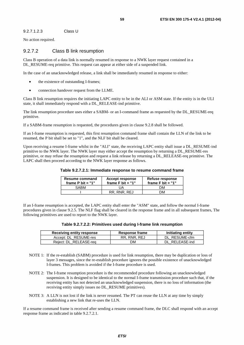
ETSI
ETSI EN 300 175-4 V2.4.1 (2012-04) 59
9.2.7.1.2.3 Class U
No action required.
9.2.7.2 Class B link resumption
Class B operation of a data link is normally resumed in response to a NWK layer request contained in a DL_RESUME-req primitive. This request can appear at either side of a suspended link.
In the case of an unacknowledged release, a link shall be immediately resumed in response to either:
• the existence of outstanding I-frames;
• connection handover request from the LLME.
Class B link resumption requires the initiating LAPC entity to be in the ALI or ASM state. If the entity is in the ULI state, it shall immediately respond with a DL_RELEASE-ind primitive.
The link resumption procedure uses either a SABM- or an I-command frame as requested by the DL_RESUME-req primitive.
If a SABM-frame resumption is requested, the procedures given in clause 9.2.8 shall be followed.
If an I-frame resumption is requested, this first resumption command frame shall contain the LLN of the link to be resumed, the P bit shall be set to "1", and the NLF bit shall be cleared.
Upon receiving a resume I-frame whilst in the "ALI" state, the receiving LAPC entity shall issue a DL_RESUME-ind primitive to the NWK layer. The NWK layer may either accept the resumption by returning a DL_RESUME-res primitive, or may refuse the resumption and request a link release by returning a DL_RELEASE-req primitive. The LAPC shall then proceed according to the NWK layer response as follows.
Table 9.2.7.2.1: Immediate response to resume command frame
Resume command frame P bit = "1"
Accept response frame F bit = "1"
Refuse response frame F bit = "1"
SABM UA DM I RR, RNR, REJ DM
If an I-frame resumption is accepted, the LAPC entity shall enter the "ASM" state, and follow the normal I-frame procedures given in clause 9.2.5. The NLF flag shall be cleared in the response frame and in all subsequent frames, The following primitives are used to report to the NWK layer.
Table 9.2.7.2.2: Primitives used during I-frame link resumption
Receiving entity response Response frame Initiating entity Accept: DL_RESUME-res RR, RNR, REJ DL_RESUME-cfm Reject: DL_RELEASE-req DM DL_RELEASE-ind
NOTE 1: If the re-establish (SABM) procedure is used for link resumption, there may be duplication or loss of layer 3 messages, since the re-establish procedure ignores the possible existence of unacknowledged I-frames. This problem is avoided if the I-frame procedure is used.
NOTE 2: The I-frame resumption procedure is the recommended procedure following an unacknowledged suspension. It is designed to be identical to the normal I-frame transmission procedure such that, if the receiving entity has not detected an unacknowledged suspension, there is no loss of information (the receiving entity simply issues no DL_RESUME primitives).
NOTE 3: A LLN is not lost if the link is never resumed. The PT can reuse the LLN at any time by simply establishing a new link that re-uses the LLN.
If a resume command frame is received after sending a resume command frame, the DLC shall respond with an accept response frame as indicated in table 9.2.7.2.1.
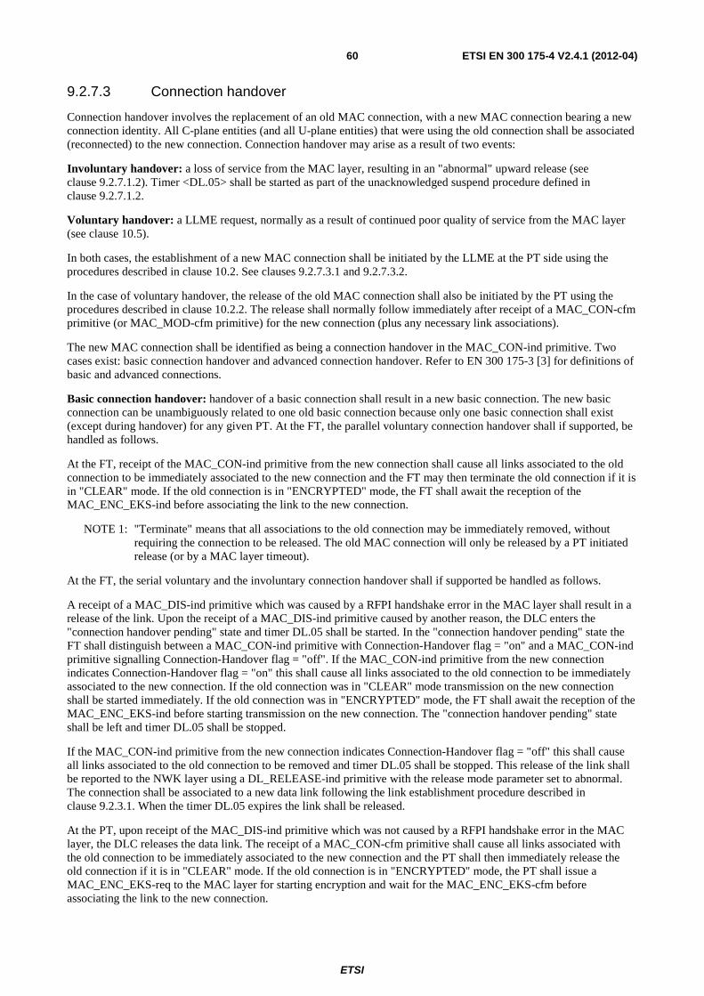
ETSI
ETSI EN 300 175-4 V2.4.1 (2012-04) 60
9.2.7.3 Connection handover
Connection handover involves the replacement of an old MAC connection, with a new MAC connection bearing a new connection identity. All C-plane entities (and all U-plane entities) that were using the old connection shall be associated (reconnected) to the new connection. Connection handover may arise as a result of two events:
Involuntary handover: a loss of service from the MAC layer, resulting in an "abnormal" upward release (see clause 9.2.7.1.2). Timer <DL.05> shall be started as part of the unacknowledged suspend procedure defined in clause 9.2.7.1.2.
Voluntary handover: a LLME request, normally as a result of continued poor quality of service from the MAC layer (see clause 10.5).
In both cases, the establishment of a new MAC connection shall be initiated by the LLME at the PT side using the procedures described in clause 10.2. See clauses 9.2.7.3.1 and 9.2.7.3.2.
In the case of voluntary handover, the release of the old MAC connection shall also be initiated by the PT using the procedures described in clause 10.2.2. The release shall normally follow immediately after receipt of a MAC_CON-cfm primitive (or MAC_MOD-cfm primitive) for the new connection (plus any necessary link associations).
The new MAC connection shall be identified as being a connection handover in the MAC_CON-ind primitive. Two cases exist: basic connection handover and advanced connection handover. Refer to EN 300 175-3 [3] for definitions of basic and advanced connections.
Basic connection handover: handover of a basic connection shall result in a new basic connection. The new basic connection can be unambiguously related to one old basic connection because only one basic connection shall exist (except during handover) for any given PT. At the FT, the parallel voluntary connection handover shall if supported, be handled as follows.
At the FT, receipt of the MAC_CON-ind primitive from the new connection shall cause all links associated to the old connection to be immediately associated to the new connection and the FT may then terminate the old connection if it is in "CLEAR" mode. If the old connection is in "ENCRYPTED" mode, the FT shall await the reception of the MAC_ENC_EKS-ind before associating the link to the new connection.
NOTE 1: "Terminate" means that all associations to the old connection may be immediately removed, without requiring the connection to be released. The old MAC connection will only be released by a PT initiated release (or by a MAC layer timeout).
At the FT, the serial voluntary and the involuntary connection handover shall if supported be handled as follows.
A receipt of a MAC_DIS-ind primitive which was caused by a RFPI handshake error in the MAC layer shall result in a release of the link. Upon the receipt of a MAC_DIS-ind primitive caused by another reason, the DLC enters the "connection handover pending" state and timer DL.05 shall be started. In the "connection handover pending" state the FT shall distinguish between a MAC_CON-ind primitive with Connection-Handover flag = "on" and a MAC_CON-ind primitive signalling Connection-Handover flag = "off". If the MAC_CON-ind primitive from the new connection indicates Connection-Handover flag = "on" this shall cause all links associated to the old connection to be immediately associated to the new connection. If the old connection was in "CLEAR" mode transmission on the new connection shall be started immediately. If the old connection was in "ENCRYPTED" mode, the FT shall await the reception of the MAC_ENC_EKS-ind before starting transmission on the new connection. The "connection handover pending" state shall be left and timer DL.05 shall be stopped.
If the MAC_CON-ind primitive from the new connection indicates Connection-Handover flag = "off" this shall cause all links associated to the old connection to be removed and timer DL.05 shall be stopped. This release of the link shall be reported to the NWK layer using a DL_RELEASE-ind primitive with the release mode parameter set to abnormal. The connection shall be associated to a new data link following the link establishment procedure described in clause 9.2.3.1. When the timer DL.05 expires the link shall be released.
At the PT, upon receipt of the MAC_DIS-ind primitive which was not caused by a RFPI handshake error in the MAC layer, the DLC releases the data link. The receipt of a MAC_CON-cfm primitive shall cause all links associated with the old connection to be immediately associated to the new connection and the PT shall then immediately release the old connection if it is in "CLEAR" mode. If the old connection is in "ENCRYPTED" mode, the PT shall issue a MAC_ENC_EKS-req to the MAC layer for starting encryption and wait for the MAC_ENC_EKS-cfm before associating the link to the new connection.
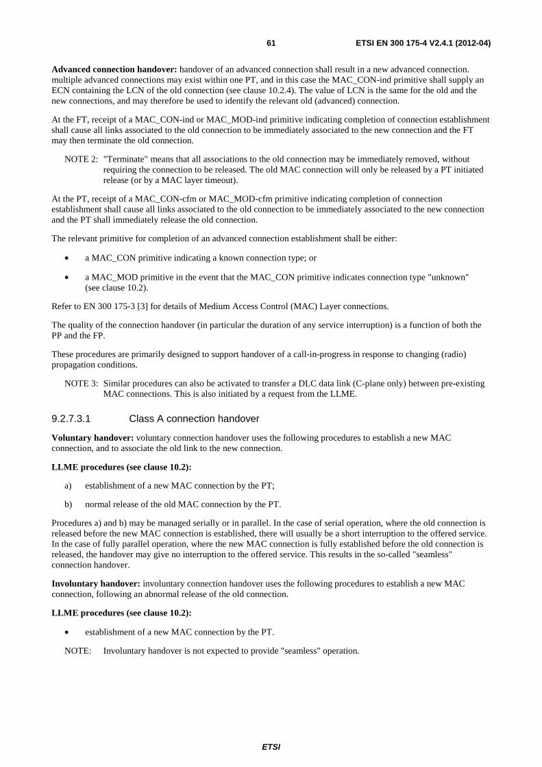
ETSI
ETSI EN 300 175-4 V2.4.1 (2012-04) 61
Advanced connection handover: handover of an advanced connection shall result in a new advanced connection. multiple advanced connections may exist within one PT, and in this case the MAC_CON-ind primitive shall supply an ECN containing the LCN of the old connection (see clause 10.2.4). The value of LCN is the same for the old and the new connections, and may therefore be used to identify the relevant old (advanced) connection.
At the FT, receipt of a MAC_CON-ind or MAC_MOD-ind primitive indicating completion of connection establishment shall cause all links associated to the old connection to be immediately associated to the new connection and the FT may then terminate the old connection.
NOTE 2: "Terminate" means that all associations to the old connection may be immediately removed, without requiring the connection to be released. The old MAC connection will only be released by a PT initiated release (or by a MAC layer timeout).
At the PT, receipt of a MAC_CON-cfm or MAC_MOD-cfm primitive indicating completion of connection establishment shall cause all links associated to the old connection to be immediately associated to the new connection and the PT shall immediately release the old connection.
The relevant primitive for completion of an advanced connection establishment shall be either:
• a MAC_CON primitive indicating a known connection type; or
• a MAC_MOD primitive in the event that the MAC_CON primitive indicates connection type "unknown" (see clause 10.2).
Refer to EN 300 175-3 [3] for details of Medium Access Control (MAC) Layer connections.
The quality of the connection handover (in particular the duration of any service interruption) is a function of both the PP and the FP.
These procedures are primarily designed to support handover of a call-in-progress in response to changing (radio) propagation conditions.
NOTE 3: Similar procedures can also be activated to transfer a DLC data link (C-plane only) between pre-existing MAC connections. This is also initiated by a request from the LLME.
9.2.7.3.1 Class A connection handover
Voluntary handover: voluntary connection handover uses the following procedures to establish a new MAC connection, and to associate the old link to the new connection.
LLME procedures (see clause 10.2):
a) establishment of a new MAC connection by the PT;
b) normal release of the old MAC connection by the PT.
Procedures a) and b) may be managed serially or in parallel. In the case of serial operation, where the old connection is released before the new MAC connection is established, there will usually be a short interruption to the offered service. In the case of fully parallel operation, where the new MAC connection is fully established before the old connection is released, the handover may give no interruption to the offered service. This results in the so-called "seamless" connection handover.
Involuntary handover: involuntary connection handover uses the following procedures to establish a new MAC connection, following an abnormal release of the old connection.
LLME procedures (see clause 10.2):
• establishment of a new MAC connection by the PT.
NOTE: Involuntary handover is not expected to provide "seamless" operation.
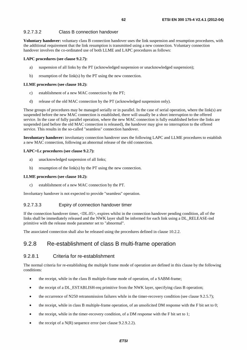
ETSI
ETSI EN 300 175-4 V2.4.1 (2012-04) 62
9.2.7.3.2 Class B connection handover
Voluntary handover: voluntary class B connection handover uses the link suspension and resumption procedures, with the additional requirement that the link resumption is transmitted using a new connection. Voluntary connection handover involves the co-ordinated use of both LLME and LAPC procedures as follows:
LAPC procedures (see clause 9.2.7):
a) suspension of all links by the PT (acknowledged suspension or unacknowledged suspension);
b) resumption of the link(s) by the PT using the new connection.
LLME procedures (see clause 10.2):
c) establishment of a new MAC connection by the PT;
d) release of the old MAC connection by the PT (acknowledged suspension only).
These groups of procedures may be managed serially or in parallel. In the case of serial operation, where the link(s) are suspended before the new MAC connection is established, there will usually be a short interruption to the offered service. In the case of fully parallel operation, where the new MAC connection is fully established before the links are suspended (and before the old MAC connection is released), the handover may give no interruption to the offered service. This results in the so-called "seamless" connection handover.
Involuntary handover: involuntary connection handover uses the following LAPC and LLME procedures to establish a new MAC connection, following an abnormal release of the old connection.
LAPC+Lc procedures (see clause 9.2.7):
a) unacknowledged suspension of all links;
b) resumption of the link(s) by the PT using the new connection.
LLME procedures (see clause 10.2):
c) establishment of a new MAC connection by the PT.
Involuntary handover is not expected to provide "seamless" operation.
9.2.7.3.3 Expiry of connection handover timer
If the connection handover timer, <DL.05>, expires whilst in the connection handover pending condition, all of the links shall be immediately released and the NWK layer shall be informed for each link using a DL_RELEASE-ind primitive with the release mode parameter set to "abnormal".
The associated connection shall also be released using the procedures defined in clause 10.2.2.
9.2.8 Re-establishment of class B multi-frame operation
9.2.8.1 Criteria for re-establishment
The normal criteria for re-establishing the multiple frame mode of operation are defined in this clause by the following conditions:
• the receipt, while in the class B multiple-frame mode of operation, of a SABM-frame;
• the receipt of a DL_ESTABLISH-req primitive from the NWK layer, specifying class B operation;
• the occurrence of N250 retransmission failures while in the timer-recovery condition (see clause 9.2.5.7);
• the receipt, while in class B multiple-frame operation, of an unsolicited DM response with the F bit set to 0;
• the receipt, while in the timer-recovery condition, of a DM response with the F bit set to 1;
• the receipt of a N(R) sequence error (see clause 9.2.9.2.2).
ETSI
ETSI EN 300 175-4 V2.4.1 (2012-04) 63
The link resumption criteria for re-establishing the multi-frame mode of operation are given by the following conditions:
• the receipt of a DL_RESUME-req primitive indicating that a SABM-frame should be used to resume a class B link.
9.2.8.2 Procedure
In all re-establishment situations, the LAPC entity shall follow the procedures defined below. All locally generated conditions for re-establishment will cause the transmission of the SABM.
The initiating LAPC, shall transmit a SABM-command frame, with the P bit set to "1". All existing exception conditions shall be cleared, the retransmission counter shall be reset and timer <DL.02> shall be started. The NLF bit shall be set in this SABM-command frame.
If the responding LAPC entity is able to accept the request, it shall respond to the receipt of the SABM-frame by issuing a DL_ESTABLISH-ind primitive to the NWK layer. Upon receipt of a DL_ESTABLISH-res primitive containing the same DLEI, it shall transmit a UA-response frame with the F bit set to the same binary value as the P bit in the SABM-frame. It shall clear all existing exception conditions, and the retransmission counter shall be reset. The NLF bit shall be set in this UA-response frame. The NLF bit shall then be cleared in all subsequent frames.
It shall then (re)enter the "ASM" state.
If the responding LAPC entity is unable to accept the request, it shall respond to the receipt of the SABM-frame by transmitting a DM-response frame with the F bit set to the same binary value as the P bit in the SABM-frame. The NLF bit shall be set in this DM-response frame.
Upon receipt of the UA response with the F bit set to "1", the originator of the SABM command shall:
• reset timer <DL.02>;
• set the sequence variables V(S) V(R) and V(A) to "0";
• (re)enter the "ASM" state;
• inform the NWK layer using a DL_ESTABLISH-cfm primitive.
Upon receipt of a DM response with the F bit set to "1", the originator of the SABM command shall indicate this to the NWK layer by means of the DL_RELEASE-ind primitive and reset timer <DL.02>. DM responses with the F bit set to "0" shall be ignored.
A DL_RELEASE-req primitive that is received during this re-establishment procedure shall be queued, and shall be serviced immediately on completion of the re-establishment procedure.
In the case of LAPC and peer initiated re-establishment, the initiating LAPC entity shall also:
• issue an indication to the lower layer management entity (LLME); and
• if V(S) > V(A) prior to re-establishment, issue a DL_ESTABLISH-ind primitive to the NWK layer, and discard all I queues.
In case of a NWK layer initiated re-establishment; or if a DL_ESTABLISH-req primitive occurs whilst re-establishment is pending, the DL_ESTABLISH-cfm primitive shall be used.
9.2.9 Exception handling
9.2.9.1 General
All unexpected or unknown frames shall be discarded. The meaning of "unknown frames" depends on the PT (or FT) capability. All frames that are not used for the relevant class of operation (class B acknowledged, class A acknowledged) are defined to be "unknown frames". The relevant frames for each class are defined in clause 7.11.
ETSI
ETSI EN 300 175-4 V2.4.1 (2012-04) 64
9.2.9.2 Class B exception condition reporting and recovery
Exception conditions may occur as the result of MAC layer errors or LAPC procedural errors. The following error recovery procedures are available to perform recovery following the detection of an exception condition at the LAPC when operating in class B.
9.2.9.2.1 N(S) sequence error
An N(S) sequence error exception condition occurs in the receiver when a valid I-frame is received which contains an N(S) value which is not equal to the V(R) at the receiver. The information field of all I-frames whose N(S) does not equal V(R) shall be discarded.
The receiver shall not acknowledge (nor increment its V(R)) as a result of the I-frame causing the sequence error, nor any I-frames which may follow, until an I-frame with the correct N(S) is received.
A LAPC entity which receives one or more I-frames having sequence errors but otherwise error-free, or subsequent supervisory frames (RR, RNR and REJ), shall use the control field information contained in the N(R) field and the P or F bit to perform LAPC control functions, for example, to receive acknowledgement of previously transmitted I-frames and to cause the LAPC entity to respond if the P bit is set to 1. Therefore, the retransmitted I-frame may contain an N(R) field value and P bit that are updated from and therefore different from, the ones contained in the originally transmitted I-frame.
The REJ-frame is used by a receiving LAPC entity to initiate an exception condition recovery (retransmission) following the detection of an N(S) sequence error.
Only one REJ exception condition for a given direction of information transfer shall be established at a time.
A LAPC entity receiving an REJ-command or response shall initiate sequential transmission (retransmission) of I-frames starting with the I-frame indicated by the N(R) contained in the REJ-frame.
A REJ exception condition is cleared when the requested I-frame is received or when an SABM or DISC command is received.
9.2.9.2.2 N(R) sequence error
A N(R) sequence error exception condition occurs in the transmitter when a valid supervisory frame or I-frame is received which contains an invalid N(R) value. A valid N(R) is one that is in the range V(A) ≤ N(R) ≤ V(S).
Upon detection of a N(R) sequence error, the LAPC entity shall immediately initiate the link re-establishment procedures according to clause 9.2.8.
The information field contained in an I-frame which is correct in both sequence and format may still be delivered to layer 3 by means of the DL_DATA-ind primitive.
9.2.9.2.3 Timer recovery condition
If a DLC entity, due to a transmission error, does not receive a single I-frame or the last I-frame(s) in a sequence of I-frames, it will not detect an out-of-sequence exception condition and therefore will not transmit a REJ-frame.
The LAPC entity which transmitted the unacknowledged I-frame(s) shall take appropriate recovery action as defined in clause 9.2.5.7 to determine at which I-frame retransmission needs to begin.
9.2.9.2.4 Collision of identical transmitted and received commands
If the transmitted and received unnumbered commands (SABM or DISC) are the same, the DLC entity shall send the UA response at the earliest possible opportunity. The indicated state shall be entered after receiving the UA response. The DLC entity shall notify the NWK layer by means of the appropriate confirm primitive.
ETSI
ETSI EN 300 175-4 V2.4.1 (2012-04) 65
9.3 Unacknowledged operation
9.3.1 Use of LLN for unacknowledged information transfer
No LLN assignment is required if the link will only be used for unacknowledged (unnumbered) information transfer.
All unacknowledged frames (UI) shall use the reserved "class U operation" value of LLN.
9.3.2 Class U link establishment
Upon receipt of a DL_ESTABLISH-req primitive indicating class U operation, the link shall be associated to an "Open" MAC connection, and if this association is successful a DL_ESTABLISH-cfm primitive shall be returned to the NWK layer. If the association is unsuccessful a DL_RELEASE-ind primitive shall be returned indicating "abnormal" release.
At the receiving side, the receipt of the first UI-frame shall result in a DL_ESTABLISH-ind primitive indicating class U operation.
9.3.3 Unacknowledged information transfer
9.3.3.1 Transmission of unacknowledged information
Unacknowledged information is passed to the DLC layer by the NWK layer using the DL_UNIT_DATA-req primitive. The complete message unit of this primitive shall be transmitted in a single UI-frame. No DLC layer error recovery procedures are defined for UI-frames (in particular, there is no retransmission of UI-frames).
The P bit shall be set to "0" and the NLF bit shall be cleared in all UI-frames.
In the event of a MAC layer failure, as indicated with a MAC_DIS-ind primitive, all UI transmission queues shall be discarded.
9.3.3.2 Reception of unacknowledged information
On receipt of a UI-command frame with a valid SAPI and LLN, the contents of the information field shall be passed to the NWK layer using the DL_UNIT-DATA-ind primitive.
Frames shall only be accepted if they contain the reserved value of LLN ("class U operation"). The P bit and the NLF flag should be ignored, and frames should be accepted with errors in either or both of these bits. All valid frames shall be immediately delivered to the NWK layer via the S-SAP.
Otherwise the UI-frame shall be discarded, and no further action shall be taken.
9.3.4 Unacknowledged release
Release of a class U link shall use the class A procedures described in clause 9.2.3.7, except that the link shall be released immediately in both the "normal" release and "abnormal" release cases. All outstanding UI-frames and all queued DL_UNIT_DATA-req primitives shall be discarded.
9.4 Broadcast operation
9.4.1 Normal operation
9.4.1.1 Procedure in the Fixed radio Termination (FT)
The normal broadcast procedure shall be initiated by the NWK layer by sending a DL_BROADCAST-req primitive. The Lb entity in the FT shall receive the complete broadcast information in a DL_BROADCAST-req primitive via the B-SAP. This primitive should also contain a list of one or more cluster addresses.
ETSI
ETSI EN 300 175-4 V2.4.1 (2012-04) 66
The DLC layer shall pass each complete frame to the MAC layer via the MA-SAP in a single MAC_PAGE-req primitive, with the page type parameter set to "normal". If several MAC layer SAPs are addressed (corresponding to different clusters), this primitive shall be duplicated and sent separately to each SAP.
Each primitive shall specify the length of the information (the length of the broadcast frame); this value shall only define one of the standard values listed in clause 6.2.1.
Alternatively, when an extended message is indicated, the extended frame format shall be used, and the message length shall define one of the extended values listed in clause 6.2.2.
9.4.1.2 Procedure in the Portable radio Termination (PT)
Upon receipt of a MAC_PAGE-ind primitive with the page type parameter set to "normal", via the MA-SAP, the Lb entity in the PT shall pass this information immediately to the NWK layer as a DL_BROADCAST-ind primitive via the B-SAP.
Each primitive shall specify the length of the information (the length of the broadcast frame); this value shall only define one of the standard values listed in clause 6.2.1. If a CRC error is indicated in the MAC_PAGE-ind primitive the error flag shall be set in the relevant DL_BROADCAST-ind primitive.
If the MAC_PAGE-ind primitive indicates a "long" message, the extended frame format shall be used, and the message length shall indicate one of the extended values listed in clause 6.2.2.
9.4.2 Expedited operation
9.4.2.1 Procedure in the Fixed radio Termination (FT)
Expedited operation shall be indicated when the Lb entity receives the broadcast information in a DL_EXPEDITED-req primitive. The Lb entity shall treat such messages as priority messages and shall process them before any queued DL_BROADCAST-req primitives. This primitive shall also contain a list of one or more cluster addresses.
The DLC layer shall pass each complete frame to the MAC layer via the MA-SAP in a single MAC_PAGE-req primitive, with the page type parameter set to "fast". If several SAPs are addressed (corresponding to different clusters), this primitive shall be duplicated and sent separately to each SAP.
Each primitive shall specify the length of the information (the length of the broadcast frame); this value shall only define one of the standard values listed in clause 6.2.1.
NOTE: Extended frames do not use the expedited procedure.
9.4.2.2 Procedure in the Portable radio Termination (PT)
Upon receipt of a MAC_PAGE-ind primitive with the page type parameter set to "fast", via the MA-SAP, the Lb entity in the PT shall pass this information immediately to the NWK layer as a DL_EXPEDITED-ind primitive via the B-SAP. Expedited information shall be processed before any queued normal broadcast information.
Each primitive shall specify the length of the information (the length of the broadcast frame); this value shall only define one of the standard values listed in clause 6.2.1. If a CRC error is indicated in the MAC_PAGE-ind primitive the error flag shall be set in the relevant DL_EXPEDITED-ind primitive.
ETSI
ETSI EN 300 175-4 V2.4.1 (2012-04) 67
9.5 MAC layer interfaces
9.5.1 MC-SAP
9.5.1.1 C-plane overview
All C-plane connection oriented (point-to-point) services shall interface with the MAC layer via the MC-SAP. The MC-SAP shall also be used to manage the underlying MAC connections, as described in clause 10.2.
Every instance of connection oriented FT LAPC+Lc (implicitly for one given PT) shall be associated to one, physical or logical, MAC connection via the MAC Connection Identifier (MCI) as defined in clause 10.2.4. Each Lc fragment shall then be transmitted to the MAC layer using one or more of the procedures (and associated primitives) described in clause 9.5.1.2. The procedure shall be selected according to the state of the associated MAC connection using the following rules:
1) if the associated MAC connection is in the "open" state, the Lc fragments shall be sent according to procedure A;
2) if the associated connection is in the "closed" state when data is scheduled for transmission, the connection shall be (re-) opened using the procedure defined in clause 10.2.1. During connection establishment, the service data shall be queued until the connection is in the "open" or "open-pending" state; as soon as the connection is in the "open" state, all queued data shall be transferred in the order of its arrival, according to procedure A. Queued data may also be sent during the "open-pending" state using procedure B;
3) if the associated MAC connection is in the "open-pending" state, the Lc fragments may be sent using procedure B.
Refer to annex C for an overview of MAC connection states as viewed by the DLC layer.
9.5.1.2 C-plane service data procedures
There are two alternative procedures for service data transfer via the MC-SAP. The procedure shall depend on the connection state as follows:
Procedure A: normal data transfer: C-plane service data may be submitted to the CS and CF logical channel of any
MAC connection that is in the "open" state, using the MAC_CO_DATA-req primitive in response to a MAC_CO_DTR-ind primitive.
NOTE: This mechanism provides flow control. Each MAC_CO_DTR-ind primitive specifies the available capacity, and the responding MAC_CO_DATA-req primitive may supply a number of fragments equal to or less than this capacity.
Procedure B: early data transfer: service data may be transferred during the "open-pending" state (see annex C), by responding to possible MAC_CO_DTR-ind primitives as defined for procedure A. However, any data transferred during the "open-pending" state shall be assumed to be lost if the connection set-up fails.
If a connection set-up fails, an automatic MAC layer re-attempt may be indicated by the arrival of a MAC_RES_DLC-ind primitive. In this event all early data that has been submitted to the connection should be resubmitted as part of the new set-up attempt.
In all cases (procedure A and procedure B), the DLC shall respond to all MAC_CO_DTR-ind primitives with a MAC_CO_DATA-req primitive indicating the number of bearers that shall be used for CS and CF data transfer in the
next TDMA frame. This response is required even if the DLC has no data scheduled for transmission. Three conditions are noted:
1) the MAC indicates that no capacity is available due to an earlier transmission failure. In this case the DLC response is required to indicate the bandwidth that shall be used for retransmission of the failed data;
ETSI
ETSI EN 300 175-4 V2.4.1 (2012-04) 68
2) the MAC indicates that some capacity is available, and the DLC has some data to send. In this case the DLC response indicates the bandwidth to be used for new transmission. The DLC may supply a number of CF or CS
data fragments equal to or less than the indicated capacity. If the DLC supplies fewer fragments than the available capacity, the MAC will nonetheless reserve all of the indicated bandwidth and will automatically generate "fill" messages to occupy any unused bandwidth;
3) the MAC indicates that some capacity is available, but the DLC has no data to send. In this case the DLC may indicate zero bandwidth, in which case the MAC is expected to use the bandwidth for U-plane data (thereby altering the U-plane bandwidth). Alternatively, the DLC may continue to reserve C-plane bandwidth by indicating a fixed bandwidth in each MAC_CO_DATA-req primitive, even though it also indicates that there are no data fragments available for transmission. This procedure shall be used to provide a dedicated CF bearer
(or bearers) and/or to maintain a constant U-plane bandwidth.
Refer also to clause 8.4.3 in EN 300 175-3 [3].
9.5.1.3 U-plane service data
The DLC is responsible for delivering U-plane data to the MAC layer MC-SAP in response to MAC layer requests.
The exact procedure is dependent on the frame type, and is defined in clause 12 for each permissible frame type.
U-plane service data may be supplied to a single MAC connection from more than one U-plane entities, provided that all the frame types are compatible with the given MAC service.
9.5.2 MB-SAP
All connectionless services, C-plane and U-plane shall interface with the MAC via the MB-SAP. The MB-SAP shall not be used to manage the underlying MAC connectionless services and shall be independent of the possible state of the underlying service.
9.5.2.1 C-plane service data procedures
Procedure A1: downlink data transfer: C-plane service data shall be duplicated (if necessary) and shall be submitted to the CLS and/or CLF logical channel, using MAC_DOWN_CON-req primitives (one per frame). For CLF services the
DLC may submit at most the maximum number of CLF segments that can be transmitted on one CL bearer in one frame. In addition the DLC may deliver one segment of CLS data every second frame.
NOTE 1: This mechanism provides no flow control. The number of DLC frame fragments is indicated in each MAC_DOWN_CON primitive using the "number of segments" parameter.
NOTE 2: The method of providing TDMA frame synchronization between MAC and DLC is not specified.
Procedure A2: uplink data transfer: C-plane service data shall be submitted to the CLS and/or CLF logical channel of
the MB-SAP, indicated in the MAC_UP_CON primitive using the "SDU length".
NOTE 3: This mechanism provides no flow control. The number of DLC frame fragments is indicated in the MAC_UP_CON primitive using the "SDU length".
9.5.2.2 U-plane service data
Connectionless service data may be supplied by any LU service defined in clause 11 as appropriate. For the fragmentation any suitable FUa fragmentation frame structure may be used, see clause 12.
NOTE 1: As the connectionless services do not provide any retransmission schemes, whenever it is possible sequencing should be provided to allow for some limited error detection at the receiving side.
Dependent on the downlink service the DLC may deliver SIN or SIP data with a MAC_DOWN_CON-req primitive.
During SIN services the DLC shall submit one segment of SIN channel data per frame. During SIP services the DLC
shall submit the maximum number of SIP segments that can be transmitted on one CL bearer in one frame.
ETSI
ETSI EN 300 175-4 V2.4.1 (2012-04) 69
NOTE 2: This mechanism provides no flow control. The number of DLC frame fragments is indicated in each MAC_DOWN_CON primitive using the "number of segments" parameter.
NOTE 3: The method of providing TDMA frame synchronization between MAC and DLC is not specified.
At the receiving side, all connectionless data per frame together with the CRC results will be received by the DLC in a MAC_DOWN_CON-ind primitive. If the B-field received was with data type set to "unknown" the DLC shall assume that the A-field was received with errors.
9.5.3 MA-SAP
9.5.3.1 Overview
All C-plane broadcast services shall interface with the MAC via the MA-SAP. The MA-SAP shall not be used to manage the underlying MAC broadcast service.
Every instance of Lb (irrespective of the PP addressed) is associated to one or more MA SAPs. Each Lb frame is then transmitted to the MAC layer using the procedure (and associated primitives) described in clause 9.4.
9.5.3.2 Service data procedures
Service data transfer via the MA-SAP shall be independent of the possible state of the underlying service.
Procedure A: normal data transfer: C-plane service data shall be duplicated (if necessary) and shall be submitted to the BS logical channel of all indicated MA-SAPs, using MAC_PAGE-req primitives.
NOTE: There is no flow control mechanism. Excess MAC_PAGE-req primitives may be discarded by the MAC layer.
10 Management procedures
10.1 Lower Layer Management Entity (LLME) The LLME shall contain the following groups of procedures that are relevant to the operation of the DLC layer:
MAC connection management: set-up, release and modification of MAC connections. Choice of CS or CF logical
channel for data transfer.
DLC C-plane management: installing and controlling the DLC C-plane resources.
DLC U-plane management: installing and controlling the DLC U-plane resources (LUx) in response to service demands from the higher layer LLME.
Connection handover management: co-ordination of connection handover functions between the C-plane and the U-plane.
Broadband data link management: set-up, release, modification and association of multiple MAC connections to one broadband data link.
Negotiation of acceptable U-plane services shall be performed by the NWK layer during the call control call establishment phase, and the agreed service demands shall be delivered directly to the DLC layer via the LLME management entity. The LLME shall then install the required service using a combination of MAC connection management (the set-up of a new connection, and/or modification of an old connection), Broadband data link management (the set-up of new connections, association with the data link and/or modification of an old connection) plus DLC U-plane management (the instancing of an LUx entity) followed by an association between the U-plane link and the MAC connection(s).
ETSI
ETSI EN 300 175-4 V2.4.1 (2012-04) 70
10.2 MAC connection management All the MAC connections shall be managed and co-ordinated within the LLME. This clause shall only describe co-ordination of the MAC connections to a single PP. Any broader co-ordination (such as may be required in complex FPs) is not described.
10.2.1 MAC connection set-up
MAC connection set-up shall be invoked by the LLME in response to service demands using the MAC_CON-req primitive. This primitive shall specify the following parameters:
• an MCEI for the new connection;
• the Connection HandOver (CHO) flag, (if the connection is required for connection handover);
• the MCEI of the old connection (only when requesting connection handover);
• the basic connection flag, (indicating if a basic connection is acceptable);
• a list of the required connection attributes (service type, slot type, etc.).
NOTE 1: The service type for advanced (non-basic) connections, may specify "U-plane unknown". In this case the attributes follow in a subsequent MAC_MOD-req primitive (see clause 10.2.3).
If the request is successful the MAC shall respond with a MAC_CON-cfm primitive to the initiating side and a MAC_CON-ind primitive to the destination side. These replies shall confirm the actual (achieved) connection attributes, and shall indicate whether a "basic" or "advanced" connection has been established. The MAC_CON-ind primitive shall also indicate connection handover (when appropriate) by using the CHO flag. For "advanced" connections, this primitive shall contain an exchanged connection number which shall define a logical connection number for the connection (see clause 10.2.4). These parameters shall be reported to the respective LLMEs at both sides.
If a connection establishment attempt fails, the MAC layer may initiate an automatic re-attempt, and shall indicate this re-attempt with a MAC_RES_DLC-ind primitive. Upon receipt of this primitive the LLME shall cause all associated DLC entities to resubmit all overlapped set-up data as described in clause 9.5.1.2.
If the connection establishment fails, the MAC shall respond with a MAC_DIS-ind primitive. This event shall be reported to the LLME, and the LLME shall invoke any appropriate recovery action. Such recovery is not specified in the present document.
NOTE 2: Suitable LLME actions include a reattempt of connection set-up, a release of the link, or a re-routing of the link to an established connection.
10.2.2 MAC connection release
MAC connections shall be released by the LLME if the NWK layer indicates that the connection is no longer required. The LLME shall first remove all link associations (such that no further data transfer is allowed). MAC connection release shall then be invoked using the MAC_DIS-req primitive. The release request shall be unacknowledged.
10.2.3 MAC connection modification
MAC connection modification is invoked using the MAC_MOD-req primitive. This primitive shall specify the following parameters:
• the MCEI for the connection;
• a list of the required connection attributes (service type, numbers of bearers, etc.).
ETSI
ETSI EN 300 175-4 V2.4.1 (2012-04) 71
MAC connection modification may be used in two ways:
Case A: To define the connection attributes of an advanced connection of service type "unknown".
Case B: To modify the type of the connection from basic to advanced or to modify the connection attributes of an advanced connection of known service type (service type, number of bearers, modulation type).
Case A shall be used during the establishment of advanced connections, whenever the MAC_CON-req primitive has specified a multi-bearer connection or the connection type as "unknown". The MAC_MOD-req primitive may be sent immediately after the MAC_CON-req on request from the LLME, but may also be delayed until a DL-SERVICE_MOD-req primitive is received from the NWK layer in order to allow some higher layer exchanges to occur using a CS/CF only MAC service. These higher layer exchanges may be used to agree the wanted service, which
shall then be invoked at the MAC layer using the MAC_MOD primitives. Case A may also be used during connection handover.
Case B shall be used after the establishment of the connection. This case may be used by the LLME to optimize the use of the resources by changing the bandwidth (including the complete reversal of unidirectional connections, MAC suspend and MAC resume procedures). In addition it may be used in response to a NWK layer request for changing the connection attributes (i.e. slot type, service type, modulation scheme). Case B service modifications shall observe the following restriction:
• CS and CF service data integrity shall always be preserved during connection modification, but changes to
connection bandwidth, modulation scheme, service type and slot type may result in data sequencing errors and/or erasures for the IN or IP logical channels.
If the "minimum bearers" parameter is changed to a value greater than the actual bandwidth, the connection will be released if the MAC cannot achieve the new requirement.
10.2.4 MAC connection identifiers
10.2.4.1 Overview
Each independently invoked MAC connection shall be uniquely identified by a MAC connection identifier (MCI). Two types of MCI are defined, corresponding to the two types of MAC connection:
• Advanced MAC Connection Identifier (AMCI) for advanced MAC connections.
• Basic MAC Connection Identifier (BMCI) for basic MAC connections.
All references to MCI shall be understood to refer to AMCI or BMCI as appropriate.
The MCI is defined to be constant for the life of the connection. In particular, it is not altered by the connection handover procedure.
During connection handover two separate connections may exist simultaneously that have the same MCI. All procedures that refer to the MCI shall be understood to refer to both connections.
NOTE: During connection handover advanced connections can be distinguished by their different advanced MAC Connection Identifiers (MCI). Basic connections cannot be distinguished.
10.2.4.2 Advanced MAC Connection Identifiers (AMCI)
Every "advanced" MAC connection to every portable radio termination is identified by an advanced MAC connection identifier:
AMCI = ARI + PMID + LCN
Where:
LCN is the constant portion of the Exchanged Connection Number (ECN) as defined below.
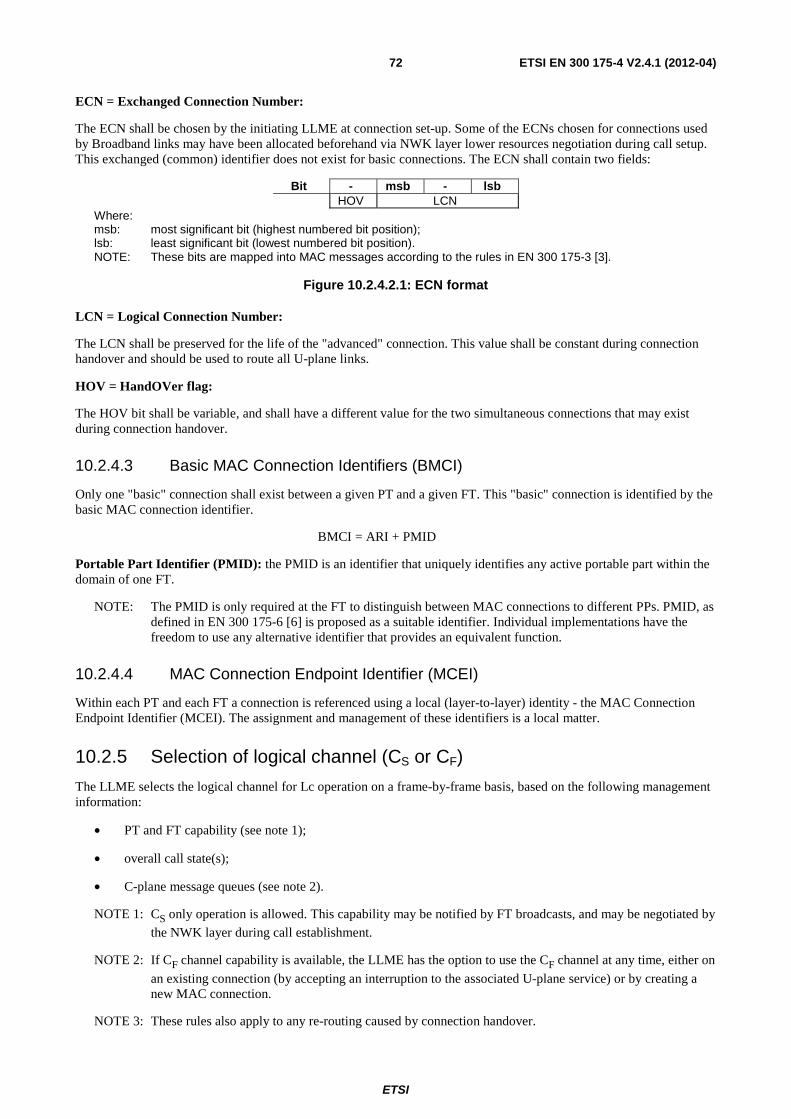
ETSI
ETSI EN 300 175-4 V2.4.1 (2012-04) 72
ECN = Exchanged Connection Number:
The ECN shall be chosen by the initiating LLME at connection set-up. Some of the ECNs chosen for connections used by Broadband links may have been allocated beforehand via NWK layer lower resources negotiation during call setup. This exchanged (common) identifier does not exist for basic connections. The ECN shall contain two fields:
Bit - msb - lsb HOV LCN
Where: msb: most significant bit (highest numbered bit position); lsb: least significant bit (lowest numbered bit position). NOTE: These bits are mapped into MAC messages according to the rules in EN 300 175-3 [3].
Figure 10.2.4.2.1: ECN format
LCN = Logical Connection Number:
The LCN shall be preserved for the life of the "advanced" connection. This value shall be constant during connection handover and should be used to route all U-plane links.
HOV = HandOVer flag:
The HOV bit shall be variable, and shall have a different value for the two simultaneous connections that may exist during connection handover.
10.2.4.3 Basic MAC Connection Identifiers (BMCI)
Only one "basic" connection shall exist between a given PT and a given FT. This "basic" connection is identified by the basic MAC connection identifier.
BMCI = ARI + PMID
Portable Part Identifier (PMID): the PMID is an identifier that uniquely identifies any active portable part within the domain of one FT.
NOTE: The PMID is only required at the FT to distinguish between MAC connections to different PPs. PMID, as defined in EN 300 175-6 [6] is proposed as a suitable identifier. Individual implementations have the freedom to use any alternative identifier that provides an equivalent function.
10.2.4.4 MAC Connection Endpoint Identifier (MCEI)
Within each PT and each FT a connection is referenced using a local (layer-to-layer) identity - the MAC Connection Endpoint Identifier (MCEI). The assignment and management of these identifiers is a local matter.
10.2.5 Selection of logical channel (CS or CF)
The LLME selects the logical channel for Lc operation on a frame-by-frame basis, based on the following management information:
• PT and FT capability (see note 1);
• overall call state(s);
• C-plane message queues (see note 2).
NOTE 1: CS only operation is allowed. This capability may be notified by FT broadcasts, and may be negotiated by
the NWK layer during call establishment.
NOTE 2: If CF channel capability is available, the LLME has the option to use the CF channel at any time, either on
an existing connection (by accepting an interruption to the associated U-plane service) or by creating a new MAC connection.
NOTE 3: These rules also apply to any re-routing caused by connection handover.
ETSI
ETSI EN 300 175-4 V2.4.1 (2012-04) 73
Logical channel selection shall operate independently in each direction. The detailed procedure for logical channel selection is not specified as part of the present document. The selection procedure should be defined by the implementor subject to the following rules:
1) the capabilities of the peer shall be observed;
2) the CS channel should be used whenever possible;
3) there shall be no more than 1 unacknowledged I-frame when the logical channel is switched;
4) the channel shall only be switched at a frame boundary;
5) a single link (single LAPC instance) shall not use more than 1 logical channel at the same time (except during connection handover).
Rules 4) and 5) shall be understood to mean that the logical channel may only be switched when there are no outstanding (non-transmitted) fragments (see transmission notes in clauses 9.2.3.2 and 9.2.5). This ensures that the order of arrival of complete LAPC frames at the peer LAPC entity shall always be the same as the order of transmission.
10.3 DLC C-plane (LAPC) management All the DLC data links are managed and co-ordinated within the LLME. This clause only considers co-ordination of the data links to a single PP. Any broader co-ordination (such as may be required in complex FPs) is not described.
10.3.1 Provision of link signature
The link signature is derived from the MAC layer PT identity as follows:
a) if the PT has an assigned PMID for the relevant FT and the link is associated to a connection oriented MAC service:
LSIG = lower 16 bits of PMID
b) if the PT does not have an assigned PMID or the link is associated to a connectionless MAC service:
LSIG = 0000 Hex
LSIG shall be supplied by the LLME for all connection oriented services at link establishment, and shall not change even if the assignment state of PMID changes during the lifetime of the link.
An established link may be (re-)associated to any open MAC connection, but the value of LSIG shall not change as a result of a new association.
NOTE: Although a default PMID is available for connection oriented services (when an assigned PMID is not available) the default case has been defined to allow a simpler implementation for systems that do not use assigned identities.
10.3.2 Routing of connection oriented links
Each connection oriented C-plane link may be routed to any suitable MAC connection, subject to the following rules:
1) the link shall be in the "open" or "open-pending" state;
2) MAC connection resources should be used in the following order of priority:
a) resources that are permanently reserved for C-plane operation (see clause 9.5.1.2);
b) the same connection as the associated U-plane service;
c) any other existing resource.
ETSI
ETSI EN 300 175-4 V2.4.1 (2012-04) 74
10.3.3 Routing of connectionless links
A connectionless C-plane link shall be routed to one or more connectionless MAC services, via the MB-SAPs, using the data transfer procedures described in clause 9.5.2.
10.4 DLC U-plane (LUX) management The DLC U-plane service instances shall be established, initialized and released by the LLME in response to service demands from the NWK layer LLME. Existing U-plane entities may also be suspended and resumed by the LLME.
10.4.1 U-plane establishment
The U-plane service description shall be passed to the U-plane management procedures by the NWK layer management at link establishment. The LLME shall map this description into a specific DLC entity and shall associate the DLC entity to a suitable open MAC connection.
If a suitable MAC connection is already available this may be used. Alternatively, a new connection shall be opened or an existing connection shall be modified to provide the required MAC service type, using the procedures in clause 10.2. Following a successful association, the relevant connection identity (BMCI or AMCI) shall be reported to the LLME.
NOTE 1: The connection identity should be communicated to the peer entity by the NWK layer using the procedures defined in EN 300 175-5 [5].
The achieved grade of service from the MAC layer may be different from that requested. In particular, the offered bandwidth may be less than the target bandwidth requested.
If the offered service achieves the minimum requested service, the DLC shall accept the service. In the event that this minimum service is not equal to the target service, the DLC may either leave the original target unchanged or may alter the target. Whenever the target is higher than the actual, the MAC layer may attempt to upgrade the service to the target value at any time without warning.
NOTE 2: The minimum service may also be changed. If the minimum is changed to a value higher than the value achieved, the MAC may release the connection.
If the offered service does not achieve the minimum requested service, the DLC shall reject the service, shall immediately release the connection, and shall report this release to the LLME.
In the case of broadband data link the DLC entity is associated with one logical MAC connection which may comprise multiple open MAC connections. In the time of the DLC entity establishment there may be only one physical MAC connection established. If the U-plane service description and transmission rate needs require additional connections to be opened these shall be done. The rules in regard to MAC service offers described in this clause in the case of single connection links apply also for the case of a multiple connections broadband data link.
10.4.2 U-plane release
U-plane links shall be released by the LLME if the NWK layer indicates that the service is no longer required. The LLME shall first remove all associations to MAC connections (such that no further data transfer is allowed). The release shall be unacknowledged.
10.4.3 U-plane suspend and resume
When a U-plane link is temporarily not required it may be suspended by the LLME in response to a suspend demand from the NWK layer LLME. The LLME shall first remove all link associations (such that no further data transfer is allowed). All DLC resources shall be preserved, but any lower layer resources (MAC connections) shall be immediately disassociated.
NOTE: The disassociated MAC connections may be released or may be re-associated to another U-plane service.
A suspended link may be resumed by the LLME at any time in response to a resume demand from the NWK layer LLME procedures. U-plane resumption shall use the procedures described in clause 10.4.1.
ETSI
ETSI EN 300 175-4 V2.4.1 (2012-04) 75
10.5 Connection handover management The invocation of an involuntary connection handover, and the decision to perform a voluntary connection handover shall always be taken by the PT. The management procedure for connection handover is not specified as part of the present document, and shall be defined by the implementor subject to the following rules:
1) if bearer handover is also provided, any control timers shall be arranged such that single bearer failures shall result in at least one bearer handover attempt, when bearer handover is possible;
2) a basic connection shall only be handed over to a (new) basic connection, and an advanced connection shall only be handed over to a (new) advanced connection;
3) a connection modification may be combined with a connection handover. This shall allow the service type of the new connection to differ from the service type of the old connection within the limits defined for connection modification;
4) following a successful connection handover attempt, a subsequent voluntary connection handover shall not be attempted for that same connection within the following <DL.06> seconds;
5) following a failed connection handover attempt, a second attempt may be made immediately. This process may be repeated for the same connection for up to N251 attempts. Thereafter, there shall be no more attempts for this connection within the following <DL.06> seconds;
6) during connection handover any retransmissions of C-plane frames (LAPC) shall only be handled using the standard retransmission protocols according to the chosen class of operation;
7) during connection handover additional retransmissions of U-plane frames may be scheduled, subject to complying with all the retransmission rules of the chosen class of operation;
NOTE: See clause 9.2.7.3 for details of the peer-to-peer procedures.
8) the rules given in clause 10.2.5 shall also apply: C-plane transmission on the new connection shall start at a frame boundary.
In the case of logical connections, each physical connection associated with the logical connection and the broadband data link shall be treated separately.
10.6 Ciphering management
10.6.1 Ciphering management in cases where the NWK layer executes the ciphering related MM procedure
The NWK layer ciphering related procedure assumes the presence of a DLC C-plane connection.
10.6.1.1 Providing a key to the MAC layer
Upon receipt of a DL_ENC_KEY-req primitive from the NWK layer the DLC shall request the LLME for the relevant connection identities. The LLME shall respond by commanding the DLC layer to issue a MAC_ENC_KEY-req primitive to all relevant connections (all applicable values of MCEI). The LLME shall also store the MCI(s) and the encryption key to be available for a possible later connection handover or new connections associated with the same broadband data link. Any earlier stored cipher key for the same MCI shall be overwritten.
NOTE: The MCI(s) are derived from the connection identities listed in the DL_ENC_KEY primitive.
In the case of broadband data links, the provision of the MCI of the first established connection (i.e. the MCI used for the DLI) shall be understood as that MAC_ENC_KEY-req primitive shall be issued to all connections associated with that broadband data link.
ETSI
ETSI EN 300 175-4 V2.4.1 (2012-04) 76
10.6.1.2 Starting and stopping the ciphering
Upon receipt of a DL_ENCRYPT-req primitive from the NWK layer the DLC shall request the LLME for the relevant connection identities. The LLME shall respond by commanding the DLC layer to issue a MAC_ENC_EKS-req primitive to all relevant MAC connections indicating "Crypted" or "Clear" as appropriate. The LLME shall also store the MCI(s) and the "Encrypt"/"Clear" status to be available for a possible later connection handover or new connections associated with the same broadband data link. Any earlier stored status for the same MCI shall be overwritten.
NOTE 1: The MCI(s) are derived from the connection identities listed in the DL_ENCRYPT primitive.
In the case of broadband data links, the provision of the MCI of the first established connection (i.e. the MCI used for the DLI) shall be understood as that MAC_ENC_EKS-req primitive shall be issued to all connections associated with that broadband data link.
All MAC_ENC_EKS primitives received from the MAC layer shall be reported to the LLME. Upon receipt of a MAC_ENC_EKS-ind (or MAC_ENC_EKS-cfm) primitive from all relevant connections the LLME shall command the DLC layer to issue a DL_ENCRYPT-ind (or DL_ENCRYPT-cfm) primitive to the NWK layer indicating the achieved status as "Encrypted" or "Clear" as appropriate. The LLME shall then store this actual "Encrypted"/"Clear" status to be available for a possible later connection handover. Any earlier stored status for the same MCI shall be overwritten.
In the case of broadband data links, the DLC shall report to NWK layer the achieved status of all established at the moment connections associated with the broadband data link. For connections established after this no report shall be issued.
NOTE 2: All connections associated with one broadband data link are assumed to have the same mode status as described in EN 300 175-3 [3].
10.6.1.3 Connection handover
During a connection handover the new connection shall always be established in clear (encryption disabled). If the status of the old connection was "crypted" then the LLME at the PT side shall command the DLC layer to enable ciphering on the new connection as soon as it is established by issuing a MAC_ENC_KEY-req primitive to the MAC layer (to provide the cipher key) followed by a MAC_ENC_EKS-req primitive with the flag set to "Go crypted".
Notification of successful encryption of the new connection shall be indicated by receipt of a MAC_ENC_EKS-cfm at the initiating side and a MAC_ENC_EKS-ind at the peer side. In this event no indication shall be issued to the NWK layer.
10.6.2 Ciphering management in cases where the NWK layer does not execute the ciphering related MM procedure
If the DLC detects a MAC_CON-ind or MAC-CON-cfm primitive indicating that a new MAC connection has been established, it shall request to the LLME whether encryption is required. If the answer is positive, the LLME provides the encryption key to the DLC. Thereafter the DLC acts as follows:
• it issues a MAC_ENC_KEY-req primitive. In the PT, this primitive is followed by a MAC_ENC-EKS req primitive;
• the DLC shall not send any data before a MAC_ENC_EKS-cfm or MAC_ENC_EKS-ind has been received.
If the answer is negative, no encryption is started and data over the MAC connection will be transferred in clear mode.
10.7 Broadband data link management Broadband data links shall be managed and co-ordinated within the LLME. This clause describes the co-ordination of the MAC connections associated with a single Broadband data link between one FT and one PT.
Broadband links may use up to three advanced MAC connections identified by their ECNs. For the management of each connection the rules specified in clause 10.2 shall apply with the additions/modifications specified in this clause.
ETSI
ETSI EN 300 175-4 V2.4.1 (2012-04) 77
NOTE: The use of only up to 3 advanced connections per a Broadband link is imposed in regard to the requirements for coexistence and capacity of DECT terminals in one and the same frequency band as specified in EN 300 175-3 [3] clause 11.6. The calculations are made on the assumption of 10 carriers used, which implies that if a wider band is in use the number of connections may be increased.
The physical connections used by a broadband data link shall be seen as a single logical connection.
The ECN for the first connection may be chosen random by the LLME, whereas the LBN for any additional connection associated with the same Broadband link shall be allocated during the NWK layer lower resources negotiation/allocation procedure at call setup time.
The assessment as how many connections will be needed for the provision of the desired service shall be based on the assessment of the agreed (again during NWK layer procedures) maximum number of UP- and DOWN-link simplex bearers. A maximum of 15 logical bearers can be associated with each connection. Each of these bearers may comprise a different number of simplex bearers depending on the bearer's type; each connection shall maintain one pilot bearer (see EN 300 175-3 [3] for details on bearer types).
After the LLME has established the required number of connections and their ECNs have been allocated by the NWK layer, the LLME shall request the connection setup of as many additional connections as needed.
The values chosen for the number of UP- and DOWN-link bearers required for each connection should respect the over all numbers agreed in the NWK layer for the particular broadband data link. The sum of the "min" UP- and DOWN-link bearers requested on all established connections shall equal the overall "min" number agreed at NWK layer. The sum of the "max" UP- and DOWN-link bearers requested on all established connections should equal the overall "max" number agreed at NWK layer. In any case, following the connections establishment, it is the MAC layer responsibility to dynamically manage suspension and resumption of these connections depending on agreed minimum bearers values and data transmission demands (see EN 300 175-3 [3] for details).
11 U-plane service characteristics
11.1 General The U-plane of the DLC layer provides for a family of alternative U-plane services as listed in clause 4.4. These services are collectively named LUX, with the individual family members being named LU1, LU2, LU3, etc. Each of these separate services is completely independent, and they are all accessed through independent LU SAPs.
Each service shall route complete Protocol Data Units (PDUs) to the MAC layer, via one of the two lower frame buffering entities, FBN or FBP. These two buffer entities correspond to the MAC layer IN unprotected services and IP
protected services respectively.
Several different LUX family members (including multiple instances of each member) may exist in complex DLC
implementations.
Every LUX entity shall use a fixed length frame format, where the frame type (and the associated frame buffering
entity) shall correspond to the MAC layer service used. Certain LUX services provide two (or more) alternative classes
of service and a different frame type (of the same fixed length) may be associated with these different classes of service.
The different frame types are defined in clause 12. The associated elements of procedure are described in clause 13, and the peer-to-peer procedures are described in clause 14.
11.2 LU1 TRansparent UnProtected service (TRUP) The LU1 service is the simplest service. It is designed to meet the special demands of speech transmission, but may also be used for non-speech applications.
The higher TRUP functions are null, and under normal conditions data is passed from the higher layer LU1 SAP to the lower FBN frame buffering function with no data alterations or additions.
LU1 shall use one of the following classes of transmission.
ETSI
ETSI EN 300 175-4 V2.4.1 (2012-04) 78
Table 11.2.1: Transmission classes for LU1 operation
Transmission class PDU Structure class 0/min_delay FU1 frame class 0 FU1 frame
Speech transmission shall only use the class 0/min_delay operation over a single bearer MAC connection. This class of operation requires a special arrangement of the buffering as described in clause 12.2.3.
Data integrity is not guaranteed. No error protection is applied, and octets may be lost, erroneous or duplicated.
NOTE 1: There are several possible sources of errors, including radio channel errors, handover errors and clock slips (e.g. small differences in clock speeds).
The (lower) frame buffering functions are provided by FBN: this shall provide synchronized fragmentation of the
continuous higher layer data into IN logical channel fragments for delivery to the IN channel in the transmit direction,
and recombination of the IN fragments into a continuous higher layer data flow in the receive direction.
The overall LU1 is a Synchronized Continuous Bitstream Oriented (SCBO) service, where octet synchronization is maintained from the lower MC SAP to the upper LU1 SAP.
NOTE 2: Octet synchronization provides 4 kHz integrity when a full slot MAC bearer is used. The IWU may interpolate 8 kHz integrity by dividing each octet in half.
LU1 is used for the following applications:
• speech;
• unprotected transparent data.
In the case of the 16-level or 64-level modulation option (see EN 300 175-2 [2]) the LU1 service may be used.
11.3 LU2 Frame RELay service (FREL)
11.3.1 General
The LU2 service is a frame relay service that is accessed through the LU2 SAP.
NOTE 1: Frame Relay service offered by LU2 is similar to the one defined in ITU-T Recommendation I.122 [i.3].
The LU2 shall operate on a generic field of user data that shall be transferred into and out of the DLC U-plane as a single SDU. This SDU is assumed to contain one external frame, but the operation of LU2 shall be independent of the actual contents of the SDU.
LU2 shall not provide the following frame relay functions:
• flag recognition, deletion and recreation;
• zero-insertion recognition, deletion and recreation;
• FCS checking, deletion and recreation;
• address translation;
• recognition and discarding of invalid frames.
If required, these functions are assumed to be provided by the user of LU2 entity.
LU2 shall provide mechanisms that offer reliable transport of the generic SDUs, and that preserve the SDU boundaries. The LU2 service shall preserve the order of SDUs, transmitted at one LU2 SAP, when they are delivered at the other end.
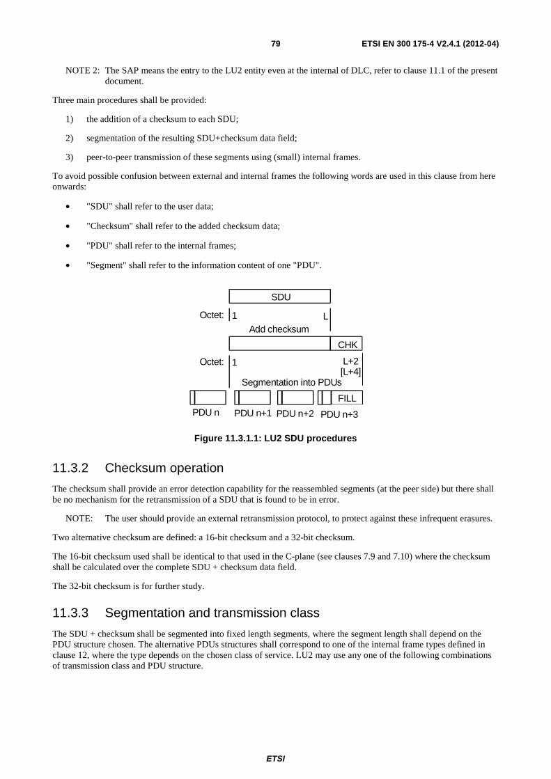
ETSI
ETSI EN 300 175-4 V2.4.1 (2012-04) 79
NOTE 2: The SAP means the entry to the LU2 entity even at the internal of DLC, refer to clause 11.1 of the present document.
Three main procedures shall be provided:
1) the addition of a checksum to each SDU;
2) segmentation of the resulting SDU+checksum data field;
3) peer-to-peer transmission of these segments using (small) internal frames.
To avoid possible confusion between external and internal frames the following words are used in this clause from here onwards:
• "SDU" shall refer to the user data;
• "Checksum" shall refer to the added checksum data;
• "PDU" shall refer to the internal frames;
• "Segment" shall refer to the information content of one "PDU".
SDU
Oc te t: 1 L Ad d c hecks um
C H K
L +2 [ L +4 ]
S e gment at i o n i n t o P D U s
P D U n PD U n +1 PD U n + 2 P D U n+3
Oc te t: 1
F I L L
Figure 11.3.1.1: LU2 SDU procedures
11.3.2 Checksum operation
The checksum shall provide an error detection capability for the reassembled segments (at the peer side) but there shall be no mechanism for the retransmission of a SDU that is found to be in error.
NOTE: The user should provide an external retransmission protocol, to protect against these infrequent erasures.
Two alternative checksum are defined: a 16-bit checksum and a 32-bit checksum.
The 16-bit checksum used shall be identical to that used in the C-plane (see clauses 7.9 and 7.10) where the checksum shall be calculated over the complete SDU + checksum data field.
The 32-bit checksum is for further study.
11.3.3 Segmentation and transmission class
The SDU + checksum shall be segmented into fixed length segments, where the segment length shall depend on the PDU structure chosen. The alternative PDUs structures shall correspond to one of the internal frame types defined in clause 12, where the type depends on the chosen class of service. LU2 may use any one of the following combinations of transmission class and PDU structure.
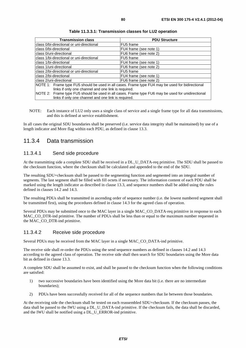
ETSI
ETSI EN 300 175-4 V2.4.1 (2012-04) 80
Table 11.3.3.1: Transmission classes for LU2 operation
Transmission class PDU Structure class 0/bi-directional or uni-directional FU5 frame class 0/bi-directional FU4 frame (see note 1) class 0/uni-directional FU6 frame (see note 2) class 1/bi-directional or uni-directional FU5 frame class 1/bi-directional FU4 frame (see note 1) class 1/uni-directional FU6 frame (see note 2) class 2/bi-directional or uni-directional FU5 frame class 2/bi-directional FU4 frame (see note 1) class 2/uni-directional FU6 frame (see note 2) NOTE 1: Frame type FU5 should be used in all cases. Frame type FU4 may be used for bidirectional
links if only one channel and one link is required. NOTE 2: Frame type FU5 should be used in all cases. Frame type FU6 may be used for unidirectional
links if only one channel and one link is required.
NOTE: Each instance of LU2 only uses a single class of service and a single frame type for all data transmissions, and this is defined at service establishment.
In all cases the original SDU boundaries shall be preserved (i.e. service data integrity shall be maintained) by use of a length indicator and More flag within each PDU, as defined in clause 13.3.
11.3.4 Data transmission
11.3.4.1 Send side procedure
At the transmitting side a complete SDU shall be received in a DL_U_DATA-req primitive. The SDU shall be passed to the checksum function, where the checksum shall be calculated and appended to the end of the SDU.
The resulting SDU+checksum shall be passed to the segmenting function and segmented into an integral number of segments. The last segment shall be filled with fill octets if necessary. The information content of each PDU shall be marked using the length indicator as described in clause 13.3, and sequence numbers shall be added using the rules defined in clauses 14.2 and 14.3.
The resulting PDUs shall be transmitted in ascending order of sequence number (i.e. the lowest numbered segment shall be transmitted first), using the procedures defined in clause 14.3 for the agreed class of operation.
Several PDUs may be submitted once to the MAC layer in a single MAC_CO_DATA-req primitive in response to each MAC_CO_DTR-ind primitive. The number of PDUs shall be less than or equal to the maximum number requested in the MAC_CO_DTR-ind primitive.
11.3.4.2 Receive side procedure
Several PDUs may be received from the MAC layer in a single MAC_CO_DATA-ind primitive.
The receive side shall re-order the PDUs using the send sequence numbers as defined in clauses 14.2 and 14.3 according to the agreed class of operation. The receive side shall then search for SDU boundaries using the More data bit as defined in clause 13.3.
A complete SDU shall be assumed to exist, and shall be passed to the checksum function when the following conditions are satisfied:
1) two successive boundaries have been identified using the More data bit (i.e. there are no intermediate boundaries);
2) PDUs have been successfully received for all of the sequence numbers that lie between those boundaries.
At the receiving side the checksum shall be tested on each reassembled SDU+checksum. If the checksum passes, the data shall be passed to the IWU using a DL_U_DATA-ind primitive. If the checksum fails, the data shall be discarded, and the IWU shall be notified using a DL_U_ERROR-ind primitive.
ETSI
ETSI EN 300 175-4 V2.4.1 (2012-04) 81
11.4 LU3 Frame SWItching service (FSWI) The LU3 service is a frame switching service that is accessed through the LU3 SAP. The higher functions are dependant on the frame type, in order to provide a detailed interaction. LU3 shall provide an internal peer-to-peer protocol called Link Access Protocol User (LAPU) which shall provide for acknowledged exchange of user data and control.
LAPU shall provide the following functions:
• management of P(S), frames sent;
• buffering of I-frames awaiting ACK;
• management of P(R), frames received;
• check received N(S) against V(R);
• acknowledge received I-frames;
• management of the V(S), V(R) state variable(s);
• detect out of sequence packets;
• generate and act upon REJ-frames;
• generate and act upon RNR- and RR-frames;
• multiplex logical channels.
The higher LAPU entity shall use the services provided by an independent instance of the LU2 entity to manage its own (LAPU) frames over the radio link.
NOTE: The LU3 service may operate on the same external (application) frame types as LU2. However, this time the external data link (layer 2) protocol is completely replaced with the LAPU protocol over the air. The translation between the external data link protocol and the LAPU protocol is assumed to be managed by the IWU. This has the advantage of requiring no modification to the external protocol timers.
LAPU shall be closely based on the LAPM procedures. These are the error control functions contained in ITU-T Recommendation V.42 [12].
The detailed specification of LU3 is defined in profile.
11.5 LU4 Forward Error Correction (FEC) service LU4 may provide a FEC service comprising FEC coding/decoding, interleaving and possibly an ARQ process.
NOTE: It may be preferable to define this service so that application specific FEC can be added external to the DECT protocol. If a de-facto FEC standard then emerges, this could be added to the DECT standard.
The following standard FEC is suggested:
• use the IN logical channel, giving 40 octet PDUs;
• use a fixed bandwidth MAC connection so that segment sequence is preserved;
• use bit-wise interleave over 1, 2, 4 or 8 TDMA frames;
• use a BCH(64,48) code, giving 30 octets of service data for each PDU;
• an optional higher frame structure of N x 30 octets can then provide ARQ if required.
The LU4 service is for further study.
ETSI
ETSI EN 300 175-4 V2.4.1 (2012-04) 82
11.6 LU5 Basic RATe adaption service (BRAT)
11.6.1 Overview
The BRAT service provides for the transparent transport of synchronous continuous data at the following basic rates:
• 64 kbit/s;
• 32 kbit/s;
• 16 kbit/s;
• 8 kbit/s.
NOTE 1: These rates allow for transparent interworking of all ISDN "B" and "D" channels. "Transparent" means that the BRAT service does not perform any flag removal or any interpretation of the data.
Two alternative classes of operation shall be defined for the BRAT service:
• Class P: protected service;
• Class N: unprotected service.
NOTE 2: These classes of service correspond to operation over either a protected MAC service (IP service) or an
unprotected MAC service (IN service) respectively. The basic functions are similar, but the detailed
operation of these two classes is different to reflect the different bandwidths of the MAC services.
The protected service should be used to provide a more reliable rate adaptation service. The protected service shall always provide notification of any errors at the receiving side. It may also offer some correction of radio path errors, although the requirement for constant (continuous) data throughput means that errors cannot always be corrected.
The unprotected service offers no error correction, and no notification of errors. This is provided as a simpler service for applications where a higher level of bit errors can be accepted.
NOTE 3: In all cases the actual error rates will depend on the radio path at the time of use. When operating with short radio paths, the unprotected service can give acceptable performance for data transmission. However, in all cases (even when using the protected class of operation) an additional higher level error protection should be used as part of any critical applications.
The maximum number of channels that can be transported by each instance of LU5 shall depend on the maximum rates selected for each channel as defined in clause 11.6.2.3 (protected operation) or clause 11.6.3.3 (unprotected operation). Multiple independent instances of LU5 may be used to provide a complete service (a complete call) to the InterWorking Unit (IWU).
Each instance of LU5 shall be distinguished by a use of a different U-plane link number (ULN) or Logical Connection Number (LCN).
NOTE 4: Each instance of LU5 can only transport one full rate (64 kbit/s) channel. Transport of several full rate (64 kbit/s) channels therefore requires the use of multiple instances of LU5.
A maximum rate shall be defined for each channel at link establishment. This rate may only be changed by re-establishing the link using the (in-call) service change procedures defined in EN 300 175-5 [5].
These maximum rates shall be agreed using the normal CC set-up procedures, based on the parameters defined in the dedicated <<rate-parameters>> information element. Refer to EN 300 175-5 [5].
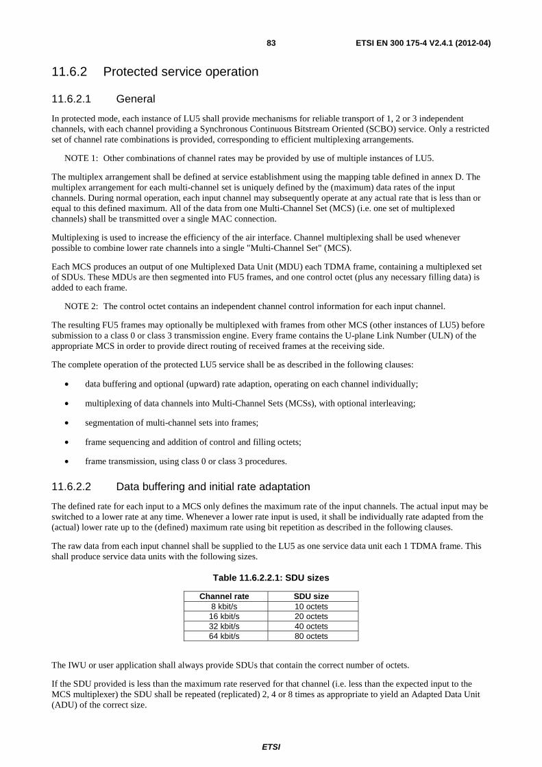
ETSI
ETSI EN 300 175-4 V2.4.1 (2012-04) 83
11.6.2 Protected service operation
11.6.2.1 General
In protected mode, each instance of LU5 shall provide mechanisms for reliable transport of 1, 2 or 3 independent channels, with each channel providing a Synchronous Continuous Bitstream Oriented (SCBO) service. Only a restricted set of channel rate combinations is provided, corresponding to efficient multiplexing arrangements.
NOTE 1: Other combinations of channel rates may be provided by use of multiple instances of LU5.
The multiplex arrangement shall be defined at service establishment using the mapping table defined in annex D. The multiplex arrangement for each multi-channel set is uniquely defined by the (maximum) data rates of the input channels. During normal operation, each input channel may subsequently operate at any actual rate that is less than or equal to this defined maximum. All of the data from one Multi-Channel Set (MCS) (i.e. one set of multiplexed channels) shall be transmitted over a single MAC connection.
Multiplexing is used to increase the efficiency of the air interface. Channel multiplexing shall be used whenever possible to combine lower rate channels into a single "Multi-Channel Set" (MCS).
Each MCS produces an output of one Multiplexed Data Unit (MDU) each TDMA frame, containing a multiplexed set of SDUs. These MDUs are then segmented into FU5 frames, and one control octet (plus any necessary filling data) is added to each frame.
NOTE 2: The control octet contains an independent channel control information for each input channel.
The resulting FU5 frames may optionally be multiplexed with frames from other MCS (other instances of LU5) before submission to a class 0 or class 3 transmission engine. Every frame contains the U-plane Link Number (ULN) of the appropriate MCS in order to provide direct routing of received frames at the receiving side.
The complete operation of the protected LU5 service shall be as described in the following clauses:
• data buffering and optional (upward) rate adaption, operating on each channel individually;
• multiplexing of data channels into Multi-Channel Sets (MCSs), with optional interleaving;
• segmentation of multi-channel sets into frames;
• frame sequencing and addition of control and filling octets;
• frame transmission, using class 0 or class 3 procedures.
11.6.2.2 Data buffering and initial rate adaptation
The defined rate for each input to a MCS only defines the maximum rate of the input channels. The actual input may be switched to a lower rate at any time. Whenever a lower rate input is used, it shall be individually rate adapted from the (actual) lower rate up to the (defined) maximum rate using bit repetition as described in the following clauses.
The raw data from each input channel shall be supplied to the LU5 as one service data unit each 1 TDMA frame. This shall produce service data units with the following sizes.
Table 11.6.2.2.1: SDU sizes
Channel rate SDU size 8 kbit/s 10 octets
16 kbit/s 20 octets 32 kbit/s 40 octets 64 kbit/s 80 octets
The IWU or user application shall always provide SDUs that contain the correct number of octets.
If the SDU provided is less than the maximum rate reserved for that channel (i.e. less than the expected input to the MCS multiplexer) the SDU shall be repeated (replicated) 2, 4 or 8 times as appropriate to yield an Adapted Data Unit (ADU) of the correct size.
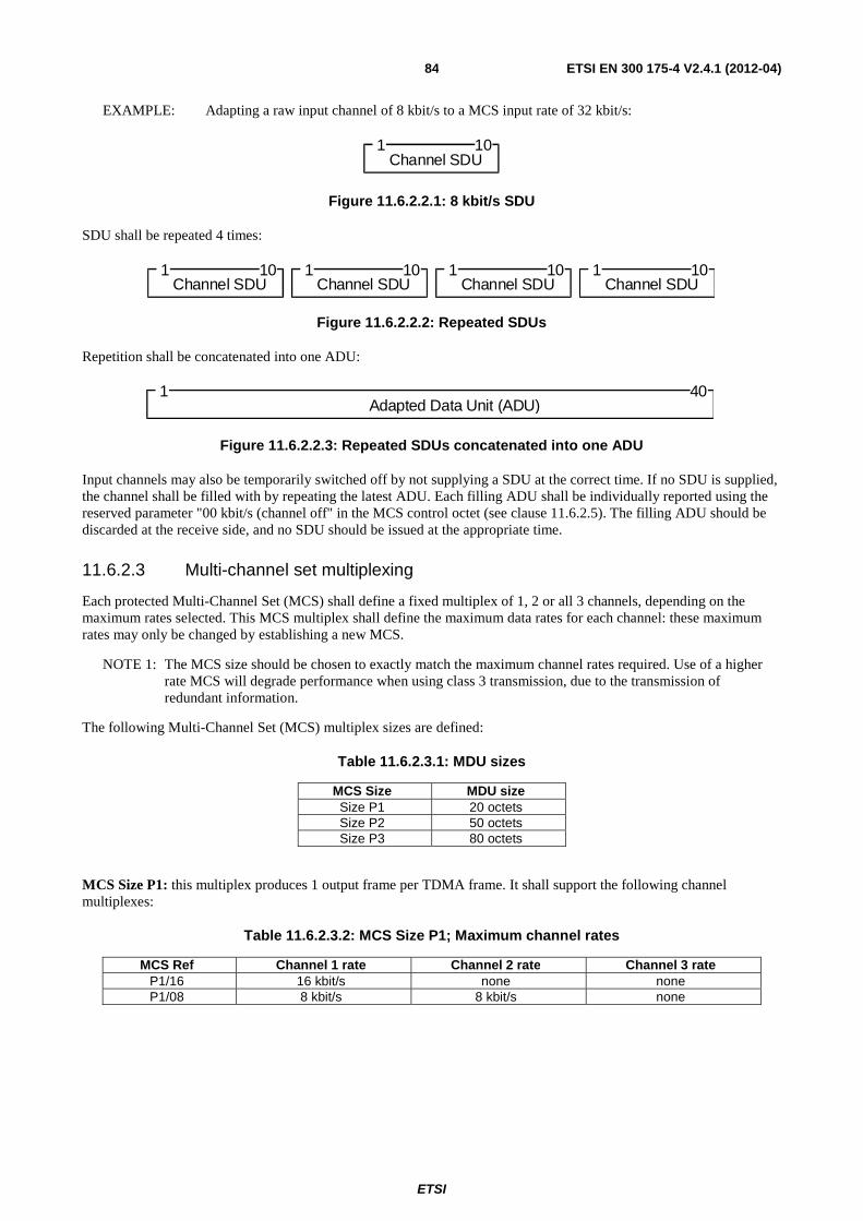
ETSI
ETSI EN 300 175-4 V2.4.1 (2012-04) 84
EXAMPLE: Adapting a raw input channel of 8 kbit/s to a MCS input rate of 32 kbit/s:
C h a n nel S D U
1 1 0
Figure 11.6.2.2.1: 8 kbit/s SDU
SDU shall be repeated 4 times:
C h a n n e l S D U
1 1 0 C h a n n e l S D U
1 1 0 C h a n n e l S D U
1 1 0 Ch a n n e l S D U
1 1 0
Figure 11.6.2.2.2: Repeated SDUs
Repetition shall be concatenated into one ADU:
Ad a p t e d D ata U ni t ( A D U )
1 40
Figure 11.6.2.2.3: Repeated SDUs concatenated into one ADU
Input channels may also be temporarily switched off by not supplying a SDU at the correct time. If no SDU is supplied, the channel shall be filled with by repeating the latest ADU. Each filling ADU shall be individually reported using the reserved parameter "00 kbit/s (channel off" in the MCS control octet (see clause 11.6.2.5). The filling ADU should be discarded at the receive side, and no SDU should be issued at the appropriate time.
11.6.2.3 Multi-channel set multiplexing
Each protected Multi-Channel Set (MCS) shall define a fixed multiplex of 1, 2 or all 3 channels, depending on the maximum rates selected. This MCS multiplex shall define the maximum data rates for each channel: these maximum rates may only be changed by establishing a new MCS.
NOTE 1: The MCS size should be chosen to exactly match the maximum channel rates required. Use of a higher rate MCS will degrade performance when using class 3 transmission, due to the transmission of redundant information.
The following Multi-Channel Set (MCS) multiplex sizes are defined:
Table 11.6.2.3.1: MDU sizes
MCS Size MDU size Size P1 20 octets Size P2 50 octets Size P3 80 octets
MCS Size P1: this multiplex produces 1 output frame per TDMA frame. It shall support the following channel multiplexes:
Table 11.6.2.3.2: MCS Size P1; Maximum channel rates
MCS Ref Channel 1 rate Channel 2 rate Channel 3 rate P1/16 16 kbit/s none none P1/08 8 kbit/s 8 kbit/s none
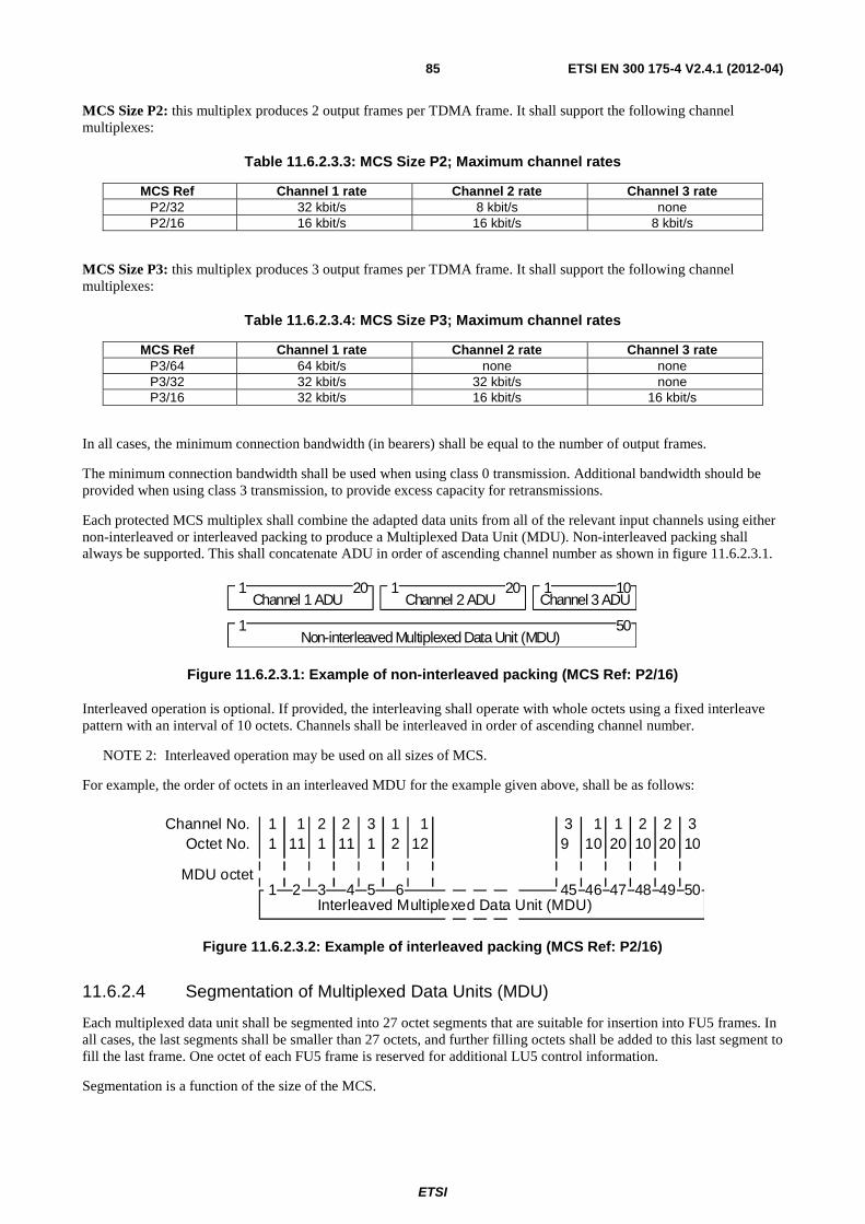
ETSI
ETSI EN 300 175-4 V2.4.1 (2012-04) 85
MCS Size P2: this multiplex produces 2 output frames per TDMA frame. It shall support the following channel multiplexes:
Table 11.6.2.3.3: MCS Size P2; Maximum channel rates
MCS Ref Channel 1 rate Channel 2 rate Channel 3 rate P2/32 32 kbit/s 8 kbit/s none P2/16 16 kbit/s 16 kbit/s 8 kbit/s
MCS Size P3: this multiplex produces 3 output frames per TDMA frame. It shall support the following channel multiplexes:
Table 11.6.2.3.4: MCS Size P3; Maximum channel rates
MCS Ref Channel 1 rate Channel 2 rate Channel 3 rate P3/64 64 kbit/s none none P3/32 32 kbit/s 32 kbit/s none P3/16 32 kbit/s 16 kbit/s 16 kbit/s
In all cases, the minimum connection bandwidth (in bearers) shall be equal to the number of output frames.
The minimum connection bandwidth shall be used when using class 0 transmission. Additional bandwidth should be provided when using class 3 transmission, to provide excess capacity for retransmissions.
Each protected MCS multiplex shall combine the adapted data units from all of the relevant input channels using either non-interleaved or interleaved packing to produce a Multiplexed Data Unit (MDU). Non-interleaved packing shall always be supported. This shall concatenate ADU in order of ascending channel number as shown in figure 11.6.2.3.1.
C h a nne l 1 AD U
1 2 0C ha nnel 2 A D U
1 20 1 10
1 50N o n- i n ter l e av ed M ult i pl e x ed D a t a U ni t ( M D U )
C h an n el 3 A D U
Figure 11.6.2.3.1: Example of non-interleaved packing (MCS Ref: P2/16)
Interleaved operation is optional. If provided, the interleaving shall operate with whole octets using a fixed interleave pattern with an interval of 10 octets. Channels shall be interleaved in order of ascending channel number.
NOTE 2: Interleaved operation may be used on all sizes of MCS.
For example, the order of octets in an interleaved MDU for the example given above, shall be as follows:
Channel No.
1Interleaved Multiplexed Data Unit (MDU)
Octet No.
MDU octet
1 2 311 121 2 1 1
111 1 1 2
2 3 4 5 6 45
3 1 29 10
1 2 32010 10 20
46 47 48 49 50
Figure 11.6.2.3.2: Example of interleaved packing (MCS Ref: P2/16)
11.6.2.4 Segmentation of Multiplexed Data Units (MDU)
Each multiplexed data unit shall be segmented into 27 octet segments that are suitable for insertion into FU5 frames. In all cases, the last segments shall be smaller than 27 octets, and further filling octets shall be added to this last segment to fill the last frame. One octet of each FU5 frame is reserved for additional LU5 control information.
Segmentation is a function of the size of the MCS.
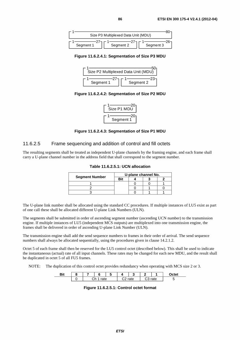
ETSI
ETSI EN 300 175-4 V2.4.1 (2012-04) 86
Segment 1 1 27
1 80Size P3 Multiplexed Data Unit (MDU)
Segment 2 1 27
Segment 3 1 26
Figure 11.6.2.4.1: Segmentation of Size P3 MDU
Segment 1 1 27
1 50Size P2 Multiplexed Data Unit (MDU)
Segment 2 1 23
Figure 11.6.2.4.2: Segmentation of Size P2 MDU
Segment 1 1 20
1Size P1 MDU
20
Figure 11.6.2.4.3: Segmentation of Size P1 MDU
11.6.2.5 Frame sequencing and addition of control and fill octets
The resulting segments shall be treated as independent U-plane channels by the framing engine, and each frame shall carry a U-plane channel number in the address field that shall correspond to the segment number.
Table 11.6.2.5.1: UCN allocation
Segment Number U-plane channel No.
Bit 4 3 2 1 0 0 1 2 0 1 0 3 0 1 1
The U-plane link number shall be allocated using the standard CC procedures. If multiple instances of LU5 exist as part of one call these shall be allocated different U-plane Link Numbers (ULN).
The segments shall be submitted in order of ascending segment number (ascending UCN number) to the transmission engine. If multiple instances of LU5 (independent MCS outputs) are multiplexed into one transmission engine, the frames shall be delivered in order of ascending U-plane Link Number (ULN).
The transmission engine shall add the send sequence numbers to frames in their order of arrival. The send sequence numbers shall always be allocated sequentially, using the procedures given in clause 14.2.1.2.
Octet 5 of each frame shall then be reserved for the LU5 control octet (described below). This shall be used to indicate the instantaneous (actual) rate of all input channels. These rates may be changed for each new MDU, and the result shall be duplicated in octet 5 of all FU5 frames.
NOTE: The duplication of this control octet provides redundancy when operating with MCS size 2 or 3.
Bit 8 7 6 5 4 3 2 1 Octet 0 Ch 1 rate C2 rate C3 rate 5
Figure 11.6.2.5.1: Control octet format
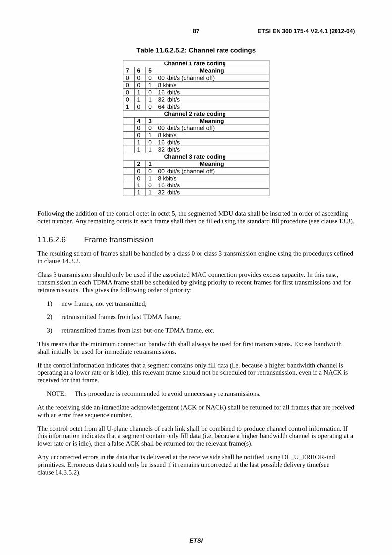
ETSI
ETSI EN 300 175-4 V2.4.1 (2012-04) 87
Table 11.6.2.5.2: Channel rate codings
Channel 1 rate coding 7 6 5 Meaning 0 0 0 00 kbit/s (channel off) 0 0 1 8 kbit/s 0 1 0 16 kbit/s 0 1 1 32 kbit/s 1 0 0 64 kbit/s
Channel 2 rate coding 4 3 Meaning 0 0 00 kbit/s (channel off) 0 1 8 kbit/s 1 0 16 kbit/s 1 1 32 kbit/s
Channel 3 rate coding 2 1 Meaning 0 0 00 kbit/s (channel off) 0 1 8 kbit/s 1 0 16 kbit/s 1 1 32 kbit/s
Following the addition of the control octet in octet 5, the segmented MDU data shall be inserted in order of ascending octet number. Any remaining octets in each frame shall then be filled using the standard fill procedure (see clause 13.3).
11.6.2.6 Frame transmission
The resulting stream of frames shall be handled by a class 0 or class 3 transmission engine using the procedures defined in clause 14.3.2.
Class 3 transmission should only be used if the associated MAC connection provides excess capacity. In this case, transmission in each TDMA frame shall be scheduled by giving priority to recent frames for first transmissions and for retransmissions. This gives the following order of priority:
1) new frames, not yet transmitted;
2) retransmitted frames from last TDMA frame;
3) retransmitted frames from last-but-one TDMA frame, etc.
This means that the minimum connection bandwidth shall always be used for first transmissions. Excess bandwidth shall initially be used for immediate retransmissions.
If the control information indicates that a segment contains only fill data (i.e. because a higher bandwidth channel is operating at a lower rate or is idle), this relevant frame should not be scheduled for retransmission, even if a NACK is received for that frame.
NOTE: This procedure is recommended to avoid unnecessary retransmissions.
At the receiving side an immediate acknowledgement (ACK or NACK) shall be returned for all frames that are received with an error free sequence number.
The control octet from all U-plane channels of each link shall be combined to produce channel control information. If this information indicates that a segment contain only fill data (i.e. because a higher bandwidth channel is operating at a lower rate or is idle), then a false ACK shall be returned for the relevant frame(s).
Any uncorrected errors in the data that is delivered at the receive side shall be notified using DL_U_ERROR-ind primitives. Erroneous data should only be issued if it remains uncorrected at the last possible delivery time(see clause 14.3.5.2).
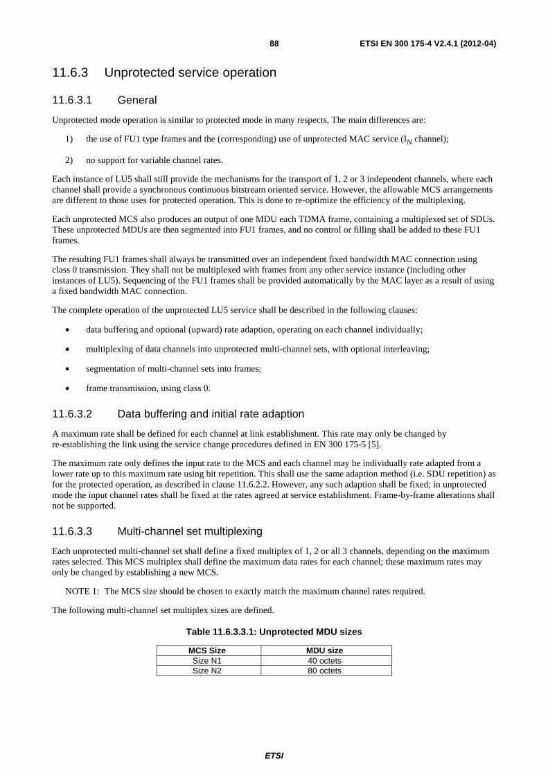
ETSI
ETSI EN 300 175-4 V2.4.1 (2012-04) 88
11.6.3 Unprotected service operation
11.6.3.1 General
Unprotected mode operation is similar to protected mode in many respects. The main differences are:
1) the use of FU1 type frames and the (corresponding) use of unprotected MAC service (IN channel);
2) no support for variable channel rates.
Each instance of LU5 shall still provide the mechanisms for the transport of 1, 2 or 3 independent channels, where each channel shall provide a synchronous continuous bitstream oriented service. However, the allowable MCS arrangements are different to those uses for protected operation. This is done to re-optimize the efficiency of the multiplexing.
Each unprotected MCS also produces an output of one MDU each TDMA frame, containing a multiplexed set of SDUs. These unprotected MDUs are then segmented into FU1 frames, and no control or filling shall be added to these FU1 frames.
The resulting FU1 frames shall always be transmitted over an independent fixed bandwidth MAC connection using class 0 transmission. They shall not be multiplexed with frames from any other service instance (including other instances of LU5). Sequencing of the FU1 frames shall be provided automatically by the MAC layer as a result of using a fixed bandwidth MAC connection.
The complete operation of the unprotected LU5 service shall be described in the following clauses:
• data buffering and optional (upward) rate adaption, operating on each channel individually;
• multiplexing of data channels into unprotected multi-channel sets, with optional interleaving;
• segmentation of multi-channel sets into frames;
• frame transmission, using class 0.
11.6.3.2 Data buffering and initial rate adaption
A maximum rate shall be defined for each channel at link establishment. This rate may only be changed by re-establishing the link using the service change procedures defined in EN 300 175-5 [5].
The maximum rate only defines the input rate to the MCS and each channel may be individually rate adapted from a lower rate up to this maximum rate using bit repetition. This shall use the same adaption method (i.e. SDU repetition) as for the protected operation, as described in clause 11.6.2.2. However, any such adaption shall be fixed; in unprotected mode the input channel rates shall be fixed at the rates agreed at service establishment. Frame-by-frame alterations shall not be supported.
11.6.3.3 Multi-channel set multiplexing
Each unprotected multi-channel set shall define a fixed multiplex of 1, 2 or all 3 channels, depending on the maximum rates selected. This MCS multiplex shall define the maximum data rates for each channel; these maximum rates may only be changed by establishing a new MCS.
NOTE 1: The MCS size should be chosen to exactly match the maximum channel rates required.
The following multi-channel set multiplex sizes are defined.
Table 11.6.3.3.1: Unprotected MDU sizes
MCS Size MDU size Size N1 40 octets Size N2 80 octets
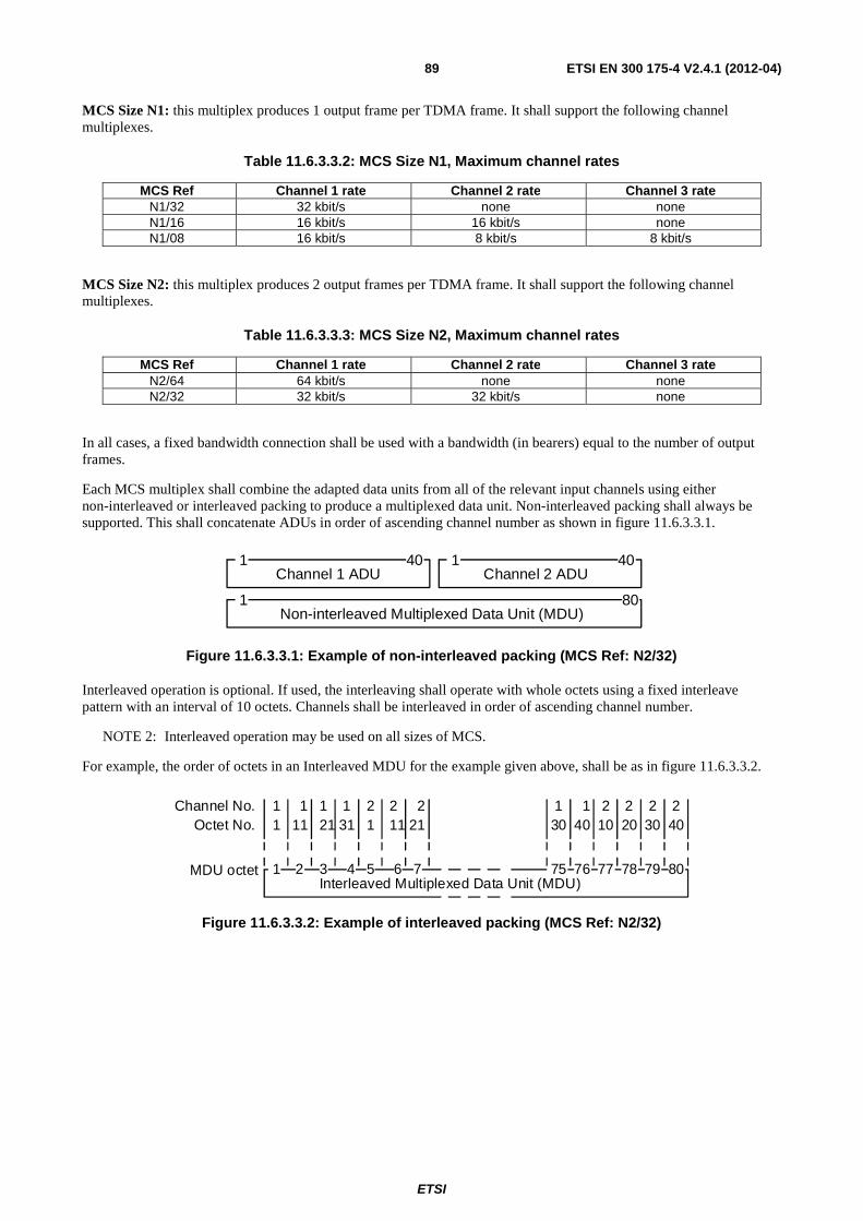
ETSI
ETSI EN 300 175-4 V2.4.1 (2012-04) 89
MCS Size N1: this multiplex produces 1 output frame per TDMA frame. It shall support the following channel multiplexes.
Table 11.6.3.3.2: MCS Size N1, Maximum channel rates
MCS Ref Channel 1 rate Channel 2 rate Channel 3 rate N1/32 32 kbit/s none none N1/16 16 kbit/s 16 kbit/s none N1/08 16 kbit/s 8 kbit/s 8 kbit/s
MCS Size N2: this multiplex produces 2 output frames per TDMA frame. It shall support the following channel multiplexes.
Table 11.6.3.3.3: MCS Size N2, Maximum channel rates
MCS Ref Channel 1 rate Channel 2 rate Channel 3 rate N2/64 64 kbit/s none none N2/32 32 kbit/s 32 kbit/s none
In all cases, a fixed bandwidth connection shall be used with a bandwidth (in bearers) equal to the number of output frames.
Each MCS multiplex shall combine the adapted data units from all of the relevant input channels using either non-interleaved or interleaved packing to produce a multiplexed data unit. Non-interleaved packing shall always be supported. This shall concatenate ADUs in order of ascending channel number as shown in figure 11.6.3.3.1.
Channel 1 ADU
1 40
1 80Non-interleaved Multiplexed Data Unit (MDU)
Channel 2 ADU 1 40
Figure 11.6.3.3.1: Example of non-interleaved packing (MCS Ref: N2/32)
Interleaved operation is optional. If used, the interleaving shall operate with whole octets using a fixed interleave pattern with an interval of 10 octets. Channels shall be interleaved in order of ascending channel number.
NOTE 2: Interleaved operation may be used on all sizes of MCS.
For example, the order of octets in an Interleaved MDU for the example given above, shall be as in figure 11.6.3.3.2.
Channel No.
1Interleaved Multiplexed Data Unit (MDU)
Octet No.
MDU octet
1 1 211 211 1 2 2
311 21 1 11
2 3 4 5 6 75
1 2 230 40
1 2 21040 20 30
76 77 78 79 807
Figure 11.6.3.3.2: Example of interleaved packing (MCS Ref: N2/32)
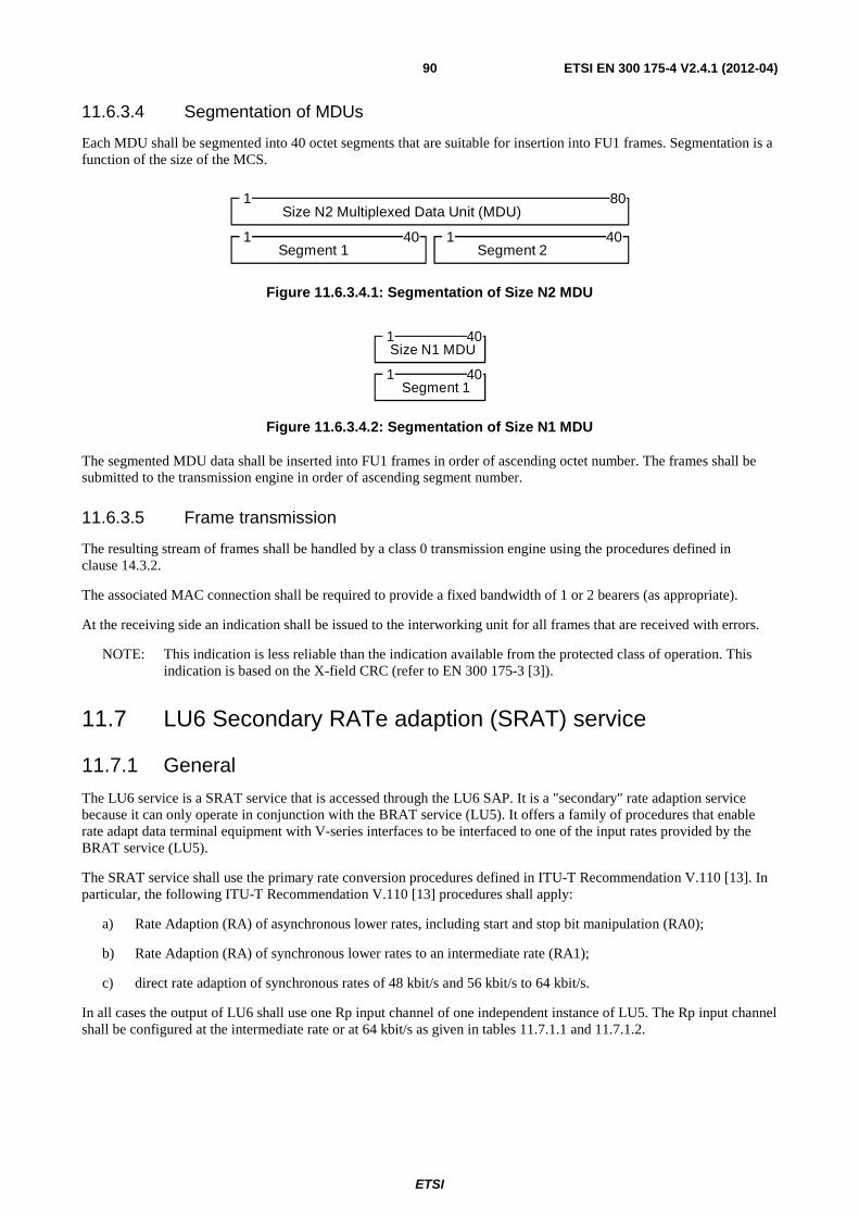
ETSI
ETSI EN 300 175-4 V2.4.1 (2012-04) 90
11.6.3.4 Segmentation of MDUs
Each MDU shall be segmented into 40 octet segments that are suitable for insertion into FU1 frames. Segmentation is a function of the size of the MCS.
Segment 1 1 40
1 80Size N2 Multiplexed Data Unit (MDU)
Segment 2 1 40
Figure 11.6.3.4.1: Segmentation of Size N2 MDU
Segment 1 1 40
1Size N1 MDU
40
Figure 11.6.3.4.2: Segmentation of Size N1 MDU
The segmented MDU data shall be inserted into FU1 frames in order of ascending octet number. The frames shall be submitted to the transmission engine in order of ascending segment number.
11.6.3.5 Frame transmission
The resulting stream of frames shall be handled by a class 0 transmission engine using the procedures defined in clause 14.3.2.
The associated MAC connection shall be required to provide a fixed bandwidth of 1 or 2 bearers (as appropriate).
At the receiving side an indication shall be issued to the interworking unit for all frames that are received with errors.
NOTE: This indication is less reliable than the indication available from the protected class of operation. This indication is based on the X-field CRC (refer to EN 300 175-3 [3]).
11.7 LU6 Secondary RATe adaption (SRAT) service
11.7.1 General
The LU6 service is a SRAT service that is accessed through the LU6 SAP. It is a "secondary" rate adaption service because it can only operate in conjunction with the BRAT service (LU5). It offers a family of procedures that enable rate adapt data terminal equipment with V-series interfaces to be interfaced to one of the input rates provided by the BRAT service (LU5).
The SRAT service shall use the primary rate conversion procedures defined in ITU-T Recommendation V.110 [13]. In particular, the following ITU-T Recommendation V.110 [13] procedures shall apply:
a) Rate Adaption (RA) of asynchronous lower rates, including start and stop bit manipulation (RA0);
b) Rate Adaption (RA) of synchronous lower rates to an intermediate rate (RA1);
c) direct rate adaption of synchronous rates of 48 kbit/s and 56 kbit/s to 64 kbit/s.
In all cases the output of LU6 shall use one Rp input channel of one independent instance of LU5. The Rp input channel shall be configured at the intermediate rate or at 64 kbit/s as given in tables 11.7.1.1 and 11.7.1.2.
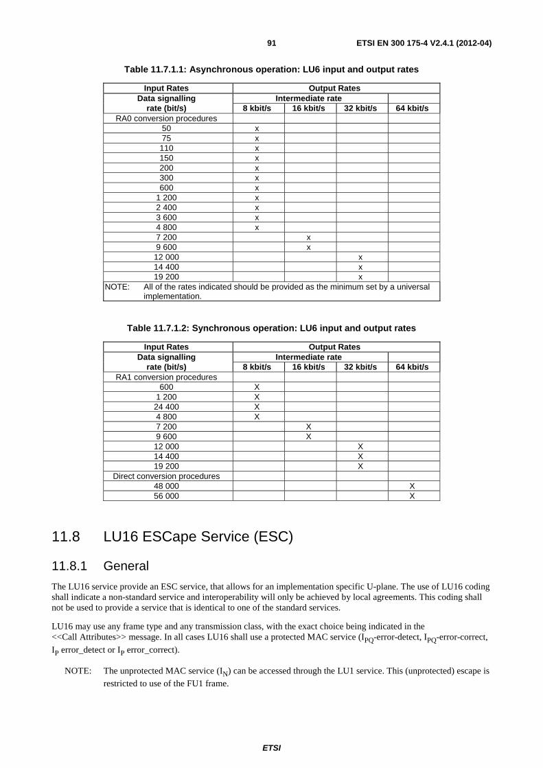
ETSI
ETSI EN 300 175-4 V2.4.1 (2012-04) 91
Table 11.7.1.1: Asynchronous operation: LU6 input and output rates
Input Rates Output Rates Data signalling Intermediate rate
rate (bit/s) 8 kbit/s 16 kbit/s 32 kbit/s 64 kbit/s RA0 conversion procedures
50 x 75 x
110 x 150 x 200 x 300 x 600 x
1 200 x 2 400 x 3 600 x 4 800 x 7 200 x 9 600 x 12 000 x 14 400 x 19 200 x
NOTE: All of the rates indicated should be provided as the minimum set by a universal implementation.
Table 11.7.1.2: Synchronous operation: LU6 input and output rates
Input Rates Output Rates Data signalling Intermediate rate
rate (bit/s) 8 kbit/s 16 kbit/s 32 kbit/s 64 kbit/s RA1 conversion procedures
600 X 1 200 X 24 400 X 4 800 X 7 200 X 9 600 X 12 000 X 14 400 X 19 200 X
Direct conversion procedures 48 000 X 56 000 X
11.8 LU16 ESCape Service (ESC)
11.8.1 General
The LU16 service provide an ESC service, that allows for an implementation specific U-plane. The use of LU16 coding shall indicate a non-standard service and interoperability will only be achieved by local agreements. This coding shall not be used to provide a service that is identical to one of the standard services.
LU16 may use any frame type and any transmission class, with the exact choice being indicated in the <<Call Attributes>> message. In all cases LU16 shall use a protected MAC service (IPQ-error-detect, IPQ-error-correct,
IP error_detect or IP error_correct).
NOTE: The unprotected MAC service (IN) can be accessed through the LU1 service. This (unprotected) escape is
restricted to use of the FU1 frame.
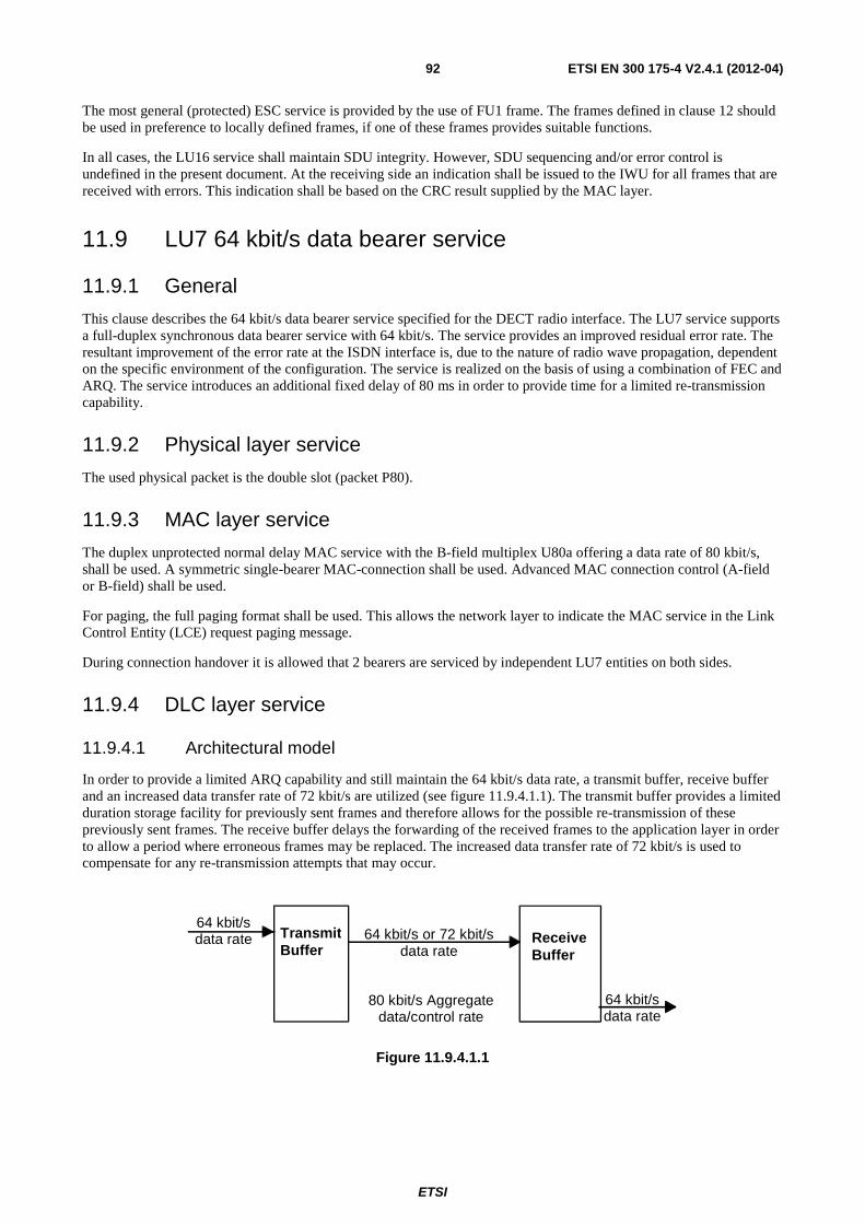
ETSI
ETSI EN 300 175-4 V2.4.1 (2012-04) 92
The most general (protected) ESC service is provided by the use of FU1 frame. The frames defined in clause 12 should be used in preference to locally defined frames, if one of these frames provides suitable functions.
In all cases, the LU16 service shall maintain SDU integrity. However, SDU sequencing and/or error control is undefined in the present document. At the receiving side an indication shall be issued to the IWU for all frames that are received with errors. This indication shall be based on the CRC result supplied by the MAC layer.
11.9 LU7 64 kbit/s data bearer service
11.9.1 General
This clause describes the 64 kbit/s data bearer service specified for the DECT radio interface. The LU7 service supports a full-duplex synchronous data bearer service with 64 kbit/s. The service provides an improved residual error rate. The resultant improvement of the error rate at the ISDN interface is, due to the nature of radio wave propagation, dependent on the specific environment of the configuration. The service is realized on the basis of using a combination of FEC and ARQ. The service introduces an additional fixed delay of 80 ms in order to provide time for a limited re-transmission capability.
11.9.2 Physical layer service
The used physical packet is the double slot (packet P80).
11.9.3 MAC layer service
The duplex unprotected normal delay MAC service with the B-field multiplex U80a offering a data rate of 80 kbit/s, shall be used. A symmetric single-bearer MAC-connection shall be used. Advanced MAC connection control (A-field or B-field) shall be used.
For paging, the full paging format shall be used. This allows the network layer to indicate the MAC service in the Link Control Entity (LCE) request paging message.
During connection handover it is allowed that 2 bearers are serviced by independent LU7 entities on both sides.
11.9.4 DLC layer service
11.9.4.1 Architectural model
In order to provide a limited ARQ capability and still maintain the 64 kbit/s data rate, a transmit buffer, receive buffer and an increased data transfer rate of 72 kbit/s are utilized (see figure 11.9.4.1.1). The transmit buffer provides a limited duration storage facility for previously sent frames and therefore allows for the possible re-transmission of these previously sent frames. The receive buffer delays the forwarding of the received frames to the application layer in order to allow a period where erroneous frames may be replaced. The increased data transfer rate of 72 kbit/s is used to compensate for any re-transmission attempts that may occur.
64 kbit/s data rate Transmit
Buffer 64 kbit/s or 72 kbit/s
data rate
80 kbit/s Aggregate data/control rate
Receive Buffer
64 kbit/s data rate
Figure 11.9.4.1.1
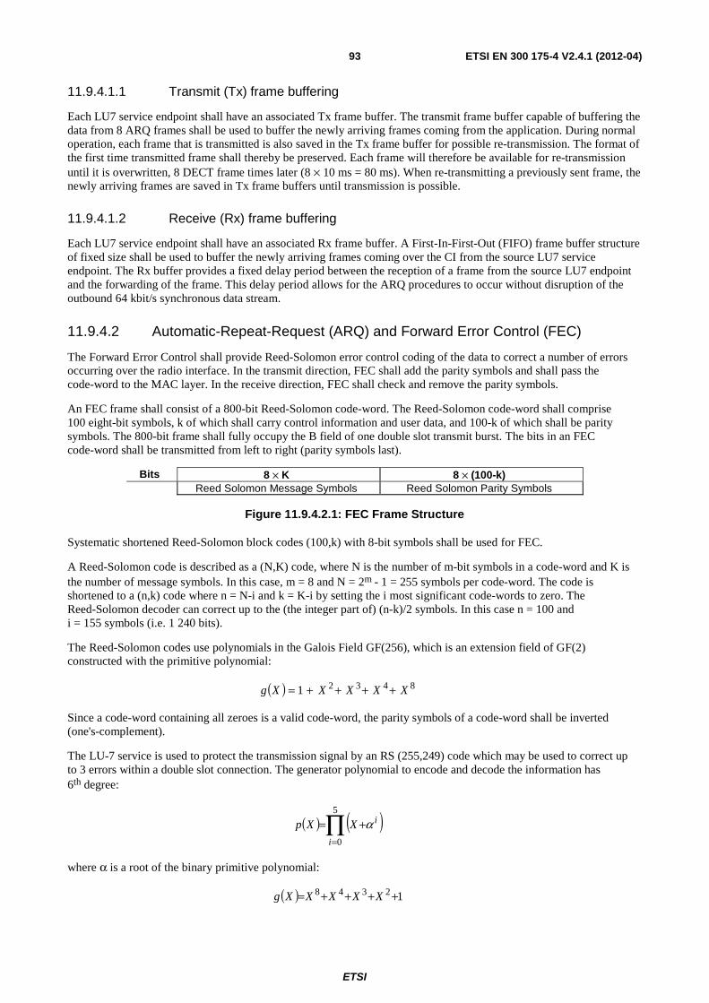
ETSI
ETSI EN 300 175-4 V2.4.1 (2012-04) 93
11.9.4.1.1 Transmit (Tx) frame buffering
Each LU7 service endpoint shall have an associated Tx frame buffer. The transmit frame buffer capable of buffering the data from 8 ARQ frames shall be used to buffer the newly arriving frames coming from the application. During normal operation, each frame that is transmitted is also saved in the Tx frame buffer for possible re-transmission. The format of the first time transmitted frame shall thereby be preserved. Each frame will therefore be available for re-transmission until it is overwritten, 8 DECT frame times later (8 × 10 ms = 80 ms). When re-transmitting a previously sent frame, the newly arriving frames are saved in Tx frame buffers until transmission is possible.
11.9.4.1.2 Receive (Rx) frame buffering
Each LU7 service endpoint shall have an associated Rx frame buffer. A First-In-First-Out (FIFO) frame buffer structure of fixed size shall be used to buffer the newly arriving frames coming over the CI from the source LU7 service endpoint. The Rx buffer provides a fixed delay period between the reception of a frame from the source LU7 endpoint and the forwarding of the frame. This delay period allows for the ARQ procedures to occur without disruption of the outbound 64 kbit/s synchronous data stream.
11.9.4.2 Automatic-Repeat-Request (ARQ) and Forward Error Control (FEC)
The Forward Error Control shall provide Reed-Solomon error control coding of the data to correct a number of errors occurring over the radio interface. In the transmit direction, FEC shall add the parity symbols and shall pass the code-word to the MAC layer. In the receive direction, FEC shall check and remove the parity symbols.
An FEC frame shall consist of a 800-bit Reed-Solomon code-word. The Reed-Solomon code-word shall comprise 100 eight-bit symbols, k of which shall carry control information and user data, and 100-k of which shall be parity symbols. The 800-bit frame shall fully occupy the B field of one double slot transmit burst. The bits in an FEC code-word shall be transmitted from left to right (parity symbols last).
Bits 8 × K 8 × (100-k) Reed Solomon Message Symbols Reed Solomon Parity Symbols
Figure 11.9.4.2.1: FEC Frame Structure
Systematic shortened Reed-Solomon block codes (100,k) with 8-bit symbols shall be used for FEC.
A Reed-Solomon code is described as a (N,K) code, where N is the number of m-bit symbols in a code-word and K is the number of message symbols. In this case, m = 8 and N = 2m - 1 = 255 symbols per code-word. The code is shortened to a (n,k) code where n = N-i and k = K-i by setting the i most significant code-words to zero. The Reed-Solomon decoder can correct up to the (the integer part of) (n-k)/2 symbols. In this case n = 100 and i = 155 symbols (i.e. 1 240 bits).
The Reed-Solomon codes use polynomials in the Galois Field GF(256), which is an extension field of GF(2) constructed with the primitive polynomial:
( ) 84321 XXXXXg ++++=
Since a code-word containing all zeroes is a valid code-word, the parity symbols of a code-word shall be inverted (one's-complement).
The LU-7 service is used to protect the transmission signal by an RS (255,249) code which may be used to correct up to 3 errors within a double slot connection. The generator polynomial to encode and decode the information has 6th degree:
( ) ( )∏=
+=5
0i
iXXp α
where α is a root of the binary primitive polynomial:
( ) 12348 ++++= XXXXXg
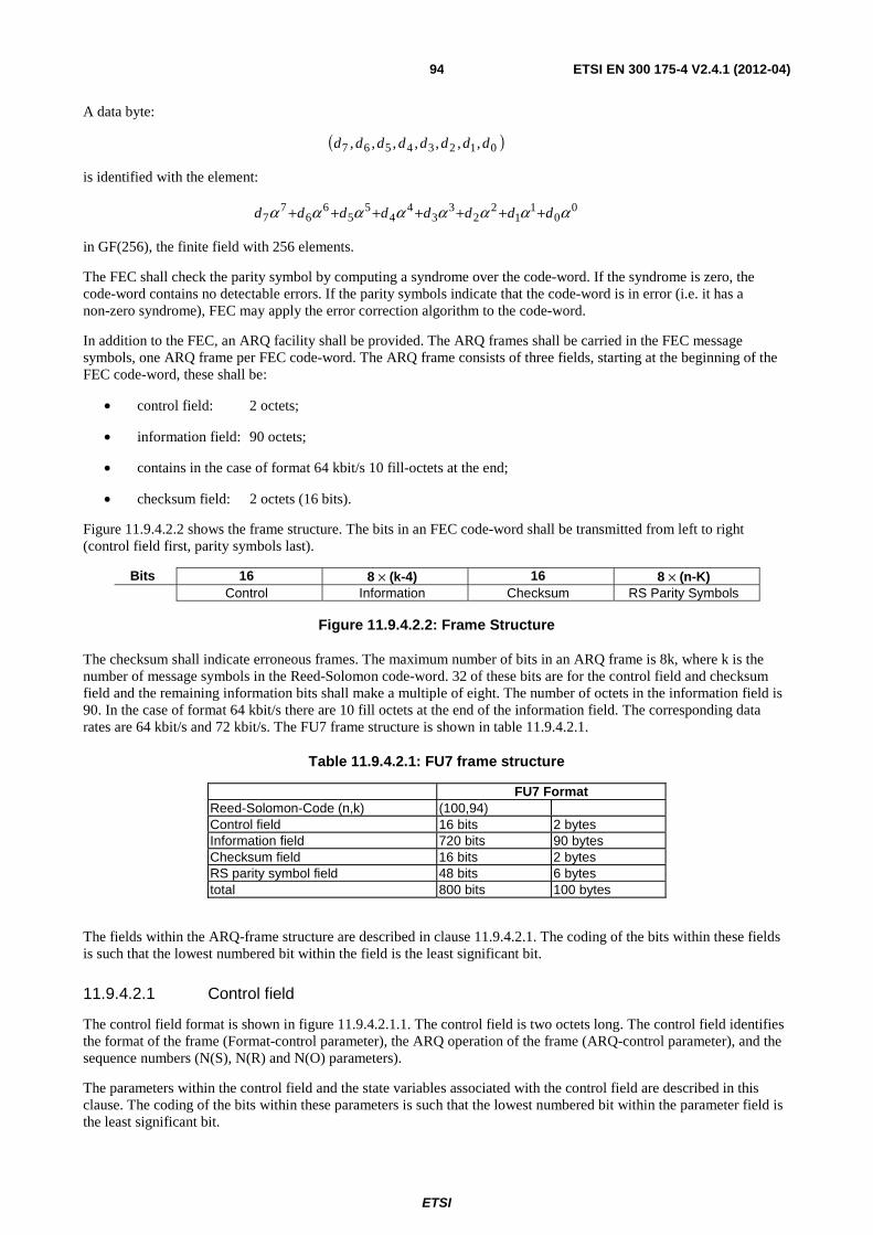
ETSI
ETSI EN 300 175-4 V2.4.1 (2012-04) 94
A data byte:
( )01234567 ,,,,,,, dddddddd
is identified with the element:
00
11
22
33
44
55
66
77 αααααααα dddddddd +++++++
in GF(256), the finite field with 256 elements.
The FEC shall check the parity symbol by computing a syndrome over the code-word. If the syndrome is zero, the code-word contains no detectable errors. If the parity symbols indicate that the code-word is in error (i.e. it has a non-zero syndrome), FEC may apply the error correction algorithm to the code-word.
In addition to the FEC, an ARQ facility shall be provided. The ARQ frames shall be carried in the FEC message symbols, one ARQ frame per FEC code-word. The ARQ frame consists of three fields, starting at the beginning of the FEC code-word, these shall be:
• control field: 2 octets;
• information field: 90 octets;
• contains in the case of format 64 kbit/s 10 fill-octets at the end;
• checksum field: 2 octets (16 bits).
Figure 11.9.4.2.2 shows the frame structure. The bits in an FEC code-word shall be transmitted from left to right (control field first, parity symbols last).
Bits 16 8 × (k-4) 16 8 × (n-K) Control Information Checksum RS Parity Symbols
Figure 11.9.4.2.2: Frame Structure
The checksum shall indicate erroneous frames. The maximum number of bits in an ARQ frame is 8k, where k is the number of message symbols in the Reed-Solomon code-word. 32 of these bits are for the control field and checksum field and the remaining information bits shall make a multiple of eight. The number of octets in the information field is 90. In the case of format 64 kbit/s there are 10 fill octets at the end of the information field. The corresponding data rates are 64 kbit/s and 72 kbit/s. The FU7 frame structure is shown in table 11.9.4.2.1.
Table 11.9.4.2.1: FU7 frame structure
FU7 Format Reed-Solomon-Code (n,k) (100,94) Control field 16 bits 2 bytes Information field 720 bits 90 bytes Checksum field 16 bits 2 bytes RS parity symbol field 48 bits 6 bytes total 800 bits 100 bytes
The fields within the ARQ-frame structure are described in clause 11.9.4.2.1. The coding of the bits within these fields is such that the lowest numbered bit within the field is the least significant bit.
11.9.4.2.1 Control field
The control field format is shown in figure 11.9.4.2.1.1. The control field is two octets long. The control field identifies the format of the frame (Format-control parameter), the ARQ operation of the frame (ARQ-control parameter), and the sequence numbers (N(S), N(R) and N(O) parameters).
The parameters within the control field and the state variables associated with the control field are described in this clause. The coding of the bits within these parameters is such that the lowest numbered bit within the parameter field is the least significant bit.
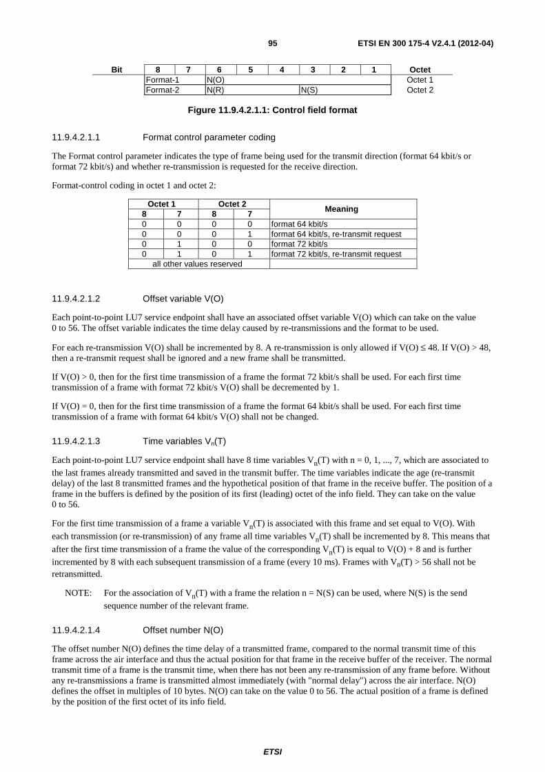
ETSI
ETSI EN 300 175-4 V2.4.1 (2012-04) 95
Bit 8 7 6 5 4 3 2 1 Octet Format-1 N(O) Octet 1 Format-2 N(R) N(S) Octet 2
Figure 11.9.4.2.1.1: Control field format
11.9.4.2.1.1 Format control parameter coding
The Format control parameter indicates the type of frame being used for the transmit direction (format 64 kbit/s or format 72 kbit/s) and whether re-transmission is requested for the receive direction.
Format-control coding in octet 1 and octet 2:
Octet 1 Octet 2 Meaning
8 7 8 7 0 0 0 0 format 64 kbit/s 0 0 0 1 format 64 kbit/s, re-transmit request 0 1 0 0 format 72 kbit/s 0 1 0 1 format 72 kbit/s, re-transmit request
all other values reserved
11.9.4.2.1.2 Offset variable V(O)
Each point-to-point LU7 service endpoint shall have an associated offset variable V(O) which can take on the value 0 to 56. The offset variable indicates the time delay caused by re-transmissions and the format to be used.
For each re-transmission V(O) shall be incremented by 8. A re-transmission is only allowed if V(O) ≤ 48. If V(O) > 48, then a re-transmit request shall be ignored and a new frame shall be transmitted.
If V(O) > 0, then for the first time transmission of a frame the format 72 kbit/s shall be used. For each first time transmission of a frame with format 72 kbit/s V(O) shall be decremented by 1.
If V(O) = 0, then for the first time transmission of a frame the format 64 kbit/s shall be used. For each first time transmission of a frame with format 64 kbit/s V(O) shall not be changed.
11.9.4.2.1.3 Time variables Vn(T)
Each point-to-point LU7 service endpoint shall have 8 time variables Vn(T) with n = 0, 1, ..., 7, which are associated to the last frames already transmitted and saved in the transmit buffer. The time variables indicate the age (re-transmit delay) of the last 8 transmitted frames and the hypothetical position of that frame in the receive buffer. The position of a frame in the buffers is defined by the position of its first (leading) octet of the info field. They can take on the value 0 to 56.
For the first time transmission of a frame a variable Vn(T) is associated with this frame and set equal to V(O). With
each transmission (or re-transmission) of any frame all time variables Vn(T) shall be incremented by 8. This means that
after the first time transmission of a frame the value of the corresponding Vn(T) is equal to V(O) + 8 and is further incremented by 8 with each subsequent transmission of a frame (every 10 ms). Frames with Vn(T) > 56 shall not be retransmitted.
NOTE: For the association of Vn(T) with a frame the relation n = N(S) can be used, where N(S) is the send sequence number of the relevant frame.
11.9.4.2.1.4 Offset number N(O)
The offset number N(O) defines the time delay of a transmitted frame, compared to the normal transmit time of this frame across the air interface and thus the actual position for that frame in the receive buffer of the receiver. The normal transmit time of a frame is the transmit time, when there has not been any re-transmission of any frame before. Without any re-transmissions a frame is transmitted almost immediately (with "normal delay") across the air interface. N(O) defines the offset in multiples of 10 bytes. N(O) can take on the value 0 to 56. The actual position of a frame is defined by the position of the first octet of its info field.

ETSI
ETSI EN 300 175-4 V2.4.1 (2012-04) 96
In the case of a first time transmission of a frame, N(O) is set equal to V(O).
In the case of a re-transmission of a frame, N(O) is set equal to that Vn(T), which corresponds to the frame that is going to be retransmitted.
Offset number N(O) in octet 1:
• 6 bit binary coded number.
11.9.4.2.1.5 Send state variable V(S)
Each point-to-point LU7 service endpoint shall have an associated V(S) state variable. V(S) denotes the sequence number of the next frame to be transmitted. V(S) can take on the value 0 to 7. The modulus of V(S) equals 8. The value of V(S) shall be incremented by 1 with each first time transmission of a frame.
NOTE: In case of a re-transmission V(S) is not incremented.
11.9.4.2.1.6 Acknowledge state variable V(A)
Each point to point LU7 service endpoint shall have an associated V(A) state variable. V(A) identifies the last frame that has been acknowledged by its peer (V(A) - 1 equals the N(S) of the last acknowledged frame, see clause 11.9.4.2.1.7). V(A) can take on the value 0 to 7. The modulus of V(A) equals 8. The value of the acknowledge state variable shall be updated by the valid N(R) values received from its peer (see clause 11.9.4.2.1.9). A valid N(R) value is one that is in the range V(A) ≤ N(R) ≤ V(S).
11.9.4.2.1.7 Send sequence number N(S)
N(S) is the send sequence number of transmitted frames. In the case of a first time transmission of a frame, N(S) is set equal to V(S). In the case of a re-transmission, N(S) is set equal to V(A).
Sending sequence number N(S) in octet 2:
• 3 bit binary coded number.
11.9.4.2.1.8 Receive state variable V(R)
Each point-to-point LU7 service endpoint shall have an associated V(R) state variable. V(R) denotes the sequence number of the next in-sequence frame expected to be received. V(R) can take on the value 0 to 7. The modulus of V(R) equals 8. Upon receipt of an error free frame whose N(S) equals V(R), the value of V(R) shall be incremented by 1 and then additionally by 1 for each subsequent error free frame in the Rx buffer.
11.9.4.2.1.9 Receive sequence number N(R)
At the time that a frame is designated for transmission, the value of N(R) is set equal to V(R). N(R) indicates that the LU7 service entity transmitting the N(R) has correctly received all frames numbered up to and including N(R)-1.
N(R) indicates the sequence number of the frame that is to be transmitted or re-transmitted.
Receiving sequence number N(R) in octet 2:
• 3 bit binary coded number.
11.9.4.2.2 Information field
The information field of a frame follows the control field and precedes the frame checksum (see clause 11.9.4.2.3). The number of octets in the information field is 90. In the case of format 64 kbit/s the information field contains 10 fill octets at the end. The fill octets shall be set to zero, if present.
NOTE: The fill octets may in future contain further service information such as whether additional formats are supported by the sending side.
ETSI
ETSI EN 300 175-4 V2.4.1 (2012-04) 97
11.9.4.2.3 ARQ checksum
The ARQ checksum shall be a sixteen-bit sequence. It shall be the ones complement of the sum (modulo 2) of:
a) the remainder of )1( 123456789101112131415 +++++++++++++++ xxxxxxxxxxxxxxxxk divided
(modulo 2) by the generator polynomial 151216 +++ xxx , where k is the number of bits of the control field (see
clause 11.9.4.2.1) and information field (see clause 11.9.4.2.2) in the FU7 frame; and
b) the remainder of the division (modulo 2) by the generator polynomial 151216 +++ xxx , of the product of 16x
by the content of the control field and information field in the FU7 frame.
As a typical implementation at the transmitter, the initial content of the register of the device computing the remainder of the division is pre-set to all 1s and is then modified by division by the generator polynomial (as described above) on the address, control, and information fields; the ones complement of the resulting remainder is transmitted as the sixteen-bit checksum.
As a typical implementation at the receiver, the initial content of the register of the device computing the remainder is
pre-set to all 1s. The final remainder after multiplication by 16x and then division (modulo 2) by the generator
polynomial 151216 +++ xxx of the serial incoming protected bits and the checksum, will be "0001 1101 0000 1111"
( 15x to 0x , respectively) in the absence of transmission errors.
11.9.4.3 Procedures for normal operation
The normal operation procedures for use by the LU7 service entity are specified in the following clauses.
11.9.4.3.1 Establishment and synchronization procedures
Upon establishment of the MAC layer connection, each LU7 service entity shall set V(S), V(R), V(A) and V(O) to 0.
Following the establishment of the MAC layer both service entities shall start transmitting valid frames e.g. if they have detected a LU7 service request in the {CC-SETUP} message received from the adjacent entity.
The information field of these frames shall be set to all "1" if the B-channel is allocated and connected.
Starting with the transmission of the first frame operations upon N(S), N(R), N(O) shall follow the normal procedures.
N(S) shall continuously be incremented while N(R) and N(O) are "0".
The entities having started the transmission shall analyse received information for a first correct frame being valid (correct CRC after FEC operation) with correct sequence numbering.
NOTE: A MAC layer B-Field set to all "0" will result in a MAC layer checksum error.
The entities shall start the timer <DLU.02> with the transmission of the first frame. The timer is stopped upon the reception of a first valid frame.
<DLU.02> LU7 timer FT value: 5 s PT value: 5 s Start: first transmission of valid LU7 frame Stop: a valid LU7 frame is received
The received information of the valid frames is stored in the receive buffer.
Commencing in that cycle carrying the first valid frame the receiver shall start forwarding dummy information (containing all "1") at its output interface for 8 consecutive cycles.
Then the service is established and the receiver takes subsequent frames to be forwarded from the information queue in its receive buffer.
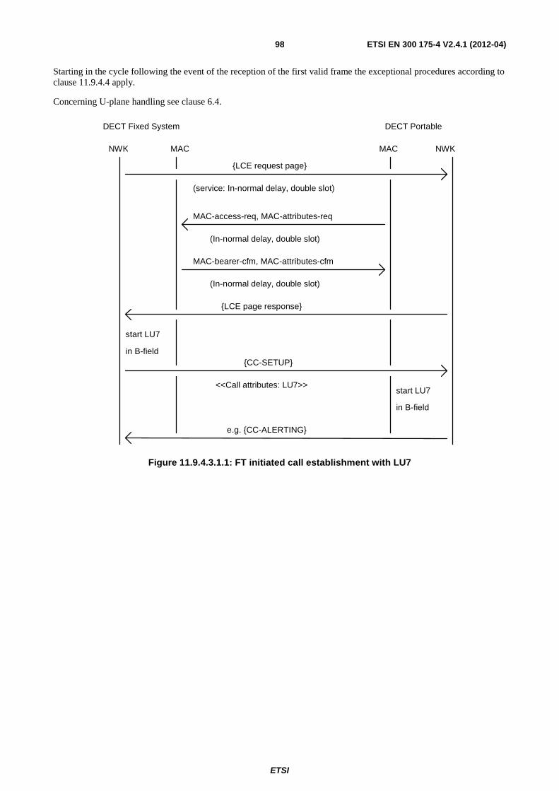
ETSI
ETSI EN 300 175-4 V2.4.1 (2012-04) 98
Starting in the cycle following the event of the reception of the first valid frame the exceptional procedures according to clause 11.9.4.4 apply.
Concerning U-plane handling see clause 6.4.
{LCE request page}
(service: In-normal delay, double slot)
MAC-access-req, MAC-attributes-req
MAC-bearer-cfm, MAC-attributes-cfm
{CC-SETUP}
<<Call attributes: LU7>>
start LU7
in B-field
start LU7
in B-field
NWK MAC MAC NWK
DECT Fixed System DECT Portable
e.g. {CC-ALERTING}
{LCE page response}
(In-normal delay, double slot)
(In-normal delay, double slot)
Figure 11.9.4.3.1.1: FT initiated call establishment with LU7
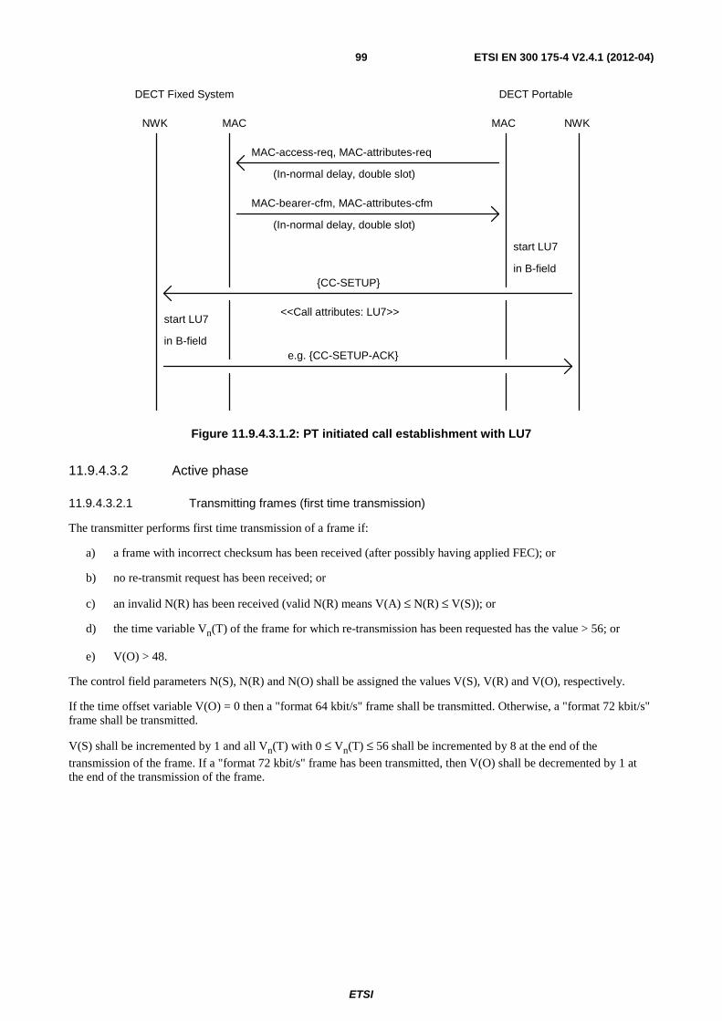
ETSI
ETSI EN 300 175-4 V2.4.1 (2012-04) 99
(In-normal delay, double slot)
MAC-access-req, MAC-attributes-req
MAC-bearer-cfm, MAC-attributes-cfm
{CC-SETUP}
<<Call attributes: LU7>>start LU7
in B-field
start LU7
in B-field
NWK MAC MAC NWK
DECT Fixed System DECT Portable
e.g. {CC-SETUP-ACK}
(In-normal delay, double slot)
Figure 11.9.4.3.1.2: PT initiated call establishment with LU7
11.9.4.3.2 Active phase
11.9.4.3.2.1 Transmitting frames (first time transmission)
The transmitter performs first time transmission of a frame if:
a) a frame with incorrect checksum has been received (after possibly having applied FEC); or
b) no re-transmit request has been received; or
c) an invalid N(R) has been received (valid N(R) means V(A) ≤ N(R) ≤ V(S)); or
d) the time variable Vn(T) of the frame for which re-transmission has been requested has the value > 56; or
e) V(O) > 48.
The control field parameters N(S), N(R) and N(O) shall be assigned the values V(S), V(R) and V(O), respectively.
If the time offset variable V(O) = 0 then a "format 64 kbit/s" frame shall be transmitted. Otherwise, a "format 72 kbit/s" frame shall be transmitted.
V(S) shall be incremented by 1 and all Vn(T) with 0 ≤ Vn(T) ≤ 56 shall be incremented by 8 at the end of the
transmission of the frame. If a "format 72 kbit/s" frame has been transmitted, then V(O) shall be decremented by 1 at the end of the transmission of the frame.
ETSI
ETSI EN 300 175-4 V2.4.1 (2012-04) 100
11.9.4.3.2.2 Re-transmitting frames
The re-transmission of a frame is requested when:
a) a frame is received containing a format control field indicating a re-transmit request for frame N(R); and
b) a valid N(R) has been received (valid N(R) means V(A) ≤ N(R) ≤ V(S)); and
c) the time variable Vn(T) of the frame N(R) for which re-transmission has been requested is in the range
0 ≤ Vn(T) ≤ 56; and
d) V(O) ≤ 48.
The control field parameter N(S) shall be set to the requested re-transmission sequence number, N(R). The control field parameter N(R) shall be set to the current value of V(R). The control field parameter N(O) shall be set to the current value of that Vn(T), which is associated to the requested frame N(S). The format, indicated by the format-control parameter coding (format 64 kbit/s or format 72 kbit/s), of the re-transmitted frame shall not be changed from the format used for the initial sending of the frame.
V(O) and all Vn(T) with 0 ≤ Vn(T) ≤ 56 shall be incremented by 8 at the end of the transmission of the frame.
11.9.4.3.2.3 Receiving frames
When an LU7 service entity receives a valid frame whose N(S) is equal to the current V(R), then the LU7 service entity shall:
• store the frame in the LU7 entity's receive buffer, the position of the frame in the receive buffer is defined by the received offset number N(O);
• update V(A) with the value of N(R);
• V(R) shall be incremented by 1 and then additionally by 1 for each subsequent error free frame in the Rx buffer;
• if the format control field indicates a re-transmit request for frame N(R) and the associated time variable Vn(T)
is in the range 0 ≤ Vn(T) ≤ 56 and V(O) ≤ 48 then the requested frame shall be re-transmitted as described in clause 11.9.4.3.2.2. Otherwise the next un-transmitted frame in the Tx buffer shall be transmitted as described in clause 11.9.4.3.2.1.
When the LU7 service entity receives a valid frame whose N(S) is greater than V(R) then the LU7 service entity shall:
• store the frame in the LU7 entity's receive buffer, the position of the frame in the receive buffer is defined by the received offset number N(O);
• update V(A) with the value of N(R);
• if the transmission of data to the line interface contained in the originally expected frame V(R) should start before a next frame can be received from the air interface, then V(R) shall be incremented by 1 and then additionally by 1 for each subsequent error free frame in the Rx buffer;
• if the format control field indicates a re-transmit request for frame N(R) and the associated time variable Vn(T)
is in the range 0 ≤ Vn(T) ≤ 56 and V(O) ≤ 48 then the requested frame shall be re-transmitted as described in clause 11.9.4.3.2.2. Otherwise the next un-transmitted frame in the Tx buffer shall be transmitted as described in clause 11.9.4.3.2.1.
ETSI
ETSI EN 300 175-4 V2.4.1 (2012-04) 101
N(O) defines the position of a frame in the receive buffer. The value N(O) = 0 means, that the transmitted frame has not been delayed because of any previous re-transmissions. A value of N(O) ≠ 0 defines the delay of the frame caused by previous re-transmissions of this or other frames. N(O) defines the delay in multiples of 10 octets, which corresponds to multiples of 1,25 ms. Therefore the time interval between the reception of a frame over the air interface and starting to forward the data to the line interface can be calculated as:
Time_interval = Fixed_delay - N(O) x 1,25 ms
where the Fixed_delay is 80 ms.
11.9.4.3.2.4 Sending acknowledgements
Whenever an LU7 service entity transmits a frame, N(R) shall be set equal to V(R), indicating acknowledgement of all previously received frames up to N(R) - 1. Thus, if no transmission errors have occurred a transmitting entity acknowledges the frames it has received in the TDMA half cycle just before. An entity shall not request re-transmission for purposes other than recovery from transmission errors.
11.9.4.3.2.5 Receiving acknowledgements
Upon receipt of a error free frame, the LU7 service entity shall treat the N(R) value contained in this frame as an acknowledgement for all the frames it has transmitted with an N(S) up to and including the received N(R) - 1 and V(A) shall be set to N(R).
11.9.4.3.3 Release
A normal release is initiated by the service primitives from the upper layer. The release of the LU7 service is combined with the MAC layer release. Therefore no additional procure is necessary.
11.9.4.4 Exceptional procedures
Exception conditions may occur as the result of physical layer errors, MAC errors, or LU7 service entity procedural errors.
The error recovery procedures which are available to perform recovery following the detection of an exception condition at the LU7 service entity are defined in this clause.
11.9.4.4.1 Invalid frame condition
A frame shall be detected as invalid if it contains a frame checksum error. The frame may be stored in the Rx buffer and marked as invalid. If an invalid frame is stored in the Rx buffer no valid data shall be overwritten.
11.9.4.4.2 Establishment
The LU7 service is started by transmitting LU7 frames. The service has been established with the reception of a correct frame and the installation of the delay. The reception of a correct frame is supervised by the timer <DLU.02>. If the timer <DLU.02> expires before a first correct frame has been received the network layer shall be informed and the entire connection shall be released.
11.9.4.4.3 Transmitting frames
First time transmission according to clause 11.9.4.3.2.1 shall continue if no valid frame has been received before.
11.9.4.4.4 Receiving frames
Handling of invalid frames that cannot be recovered in time is left to the implementation. The objective is to achieve a low residual BER.
NOTE: If an invalid frame has been received its contents may be stored in the receive buffer to have best choice data available to be forwarded if that frame cannot be recovered in time. The format just now being in use may be assumed.
ETSI
ETSI EN 300 175-4 V2.4.1 (2012-04) 102
A received valid frame which was previously requested for re-transmission shall override a possibly stored invalid frame in the receive buffer.
11.9.4.4.5 Sending acknowledgements
Retransmission of a frame shall be requested as long as a value N(0) ≤ 56 can be expected for the retransmitted frame assumed being valid.
The receiver shall otherwise acknowledge that frame according to clause 11.9.4.3.2.1.
11.9.4.4.6 Forwarding of received data
If a frame in the receive buffer cannot be recovered in time this produces a residual frame error. The bit sequence forwarded in this case is left to the implementation (see also clause 11.9.4.4.4).
11.9.4.4.7 N(R) sequence error
Unless the condition stated in clause 11.9.4.4.12 is true, the following applies.
An N(R) sequence error exception condition occurs when a frame is received which contains an invalid N(R) value.
A valid N(R) is one that is in the range V(A) ≤ N(R) ≤ V(S).
An invalid N(R) shall be ignored and normal operation upon sequencing of N(S) shall be continued.
11.9.4.4.8 N(O) sequence error
Unless the condition stated in clause 11.9.4.4.12 is true, the following applies.
An N(O) sequence error exception condition occurs when:
a) a frame is received which contains an N(O) value indicating a frame position in the RX-buffer that would overwrite already correctly received data, which has not yet been forwarded to the line interface or application; or
b) frame is received which contains an N(O) value indicating a frame position in the RX-buffer that would partly provide needed data and partly overwrite already correctly received data, which have not yet been forwarded to the line interface or application; or
c) frame is received which contains an N(O) value indicating a frame position in the RX-buffer that would leave gaps in the RX-buffer, which cannot be filled up with allowed frames without causing overlapping data; or
d) frame is received which contains an N(O) value indicating a frame position in the RX-buffer that would leave an unexpected large gap in the RX-buffer.
In case a) he received frame should be ignored. Only if the old data was marked with "position-error", then the new frame should be used.
In case b) the received frame may be ignored. Those parts which are not overwriting correct and still valid data may be used. If the old data was marked with "position-error", then the new frame should be used.
In case c) the received data should be stored and marked with "position-error".
In case d) the received data should be stored and marked with "position-error".
NOTE: The N(O) sequence error should be supervised. If the error condition continues, then the link should be released.
ETSI
ETSI EN 300 175-4 V2.4.1 (2012-04) 103
11.9.4.4.9 N(S) sequence error
Unless the condition stated in clause 11.9.4.4.12 is true, the following applies.
An N(S) sequence error exception condition occurs when:
a) a frame is received which contains a different N(S) value for an already correctly received frame; or
b) a frame is received which contains a N(S) value which has not been incremented by one compared with the preceding neighbourhood frame.
In case a) the received frame should be ignored.
In case b) the received frame should be stored and marked with "sequence-error".
NOTE: The N(S) sequence error should be supervised. If the error condition continues, then the link should be released.
11.9.4.4.10 Format error
Unless the condition stated in clause 11.9.4.4.12 is true, the following applies.
A format error condition occurs upon the receipt of a frame with an undefined format-control parameter in the control field.
The frame should be stored, if the control variable N(O) and N(S) are valid. If the format cannot be estimated unambiguously the frame should by marked with "format-error".
NOTE: The format error should be supervised. If the error condition continues, then the link should be released.
11.9.4.4.11 Abnormal release
If the MAC layer indicates abnormal release, then the LU7 service shall be released and the abnormal release shall be indicated to the higher layer.
11.9.4.4.12 Implicit reset
The unexpected receipt of a frame with both N(O), N(S) and N(R) equal to 0 by the PT entity, after a connection handover has been performed shall be considered as an implicit reset. The receiving entity shall then act according to the following procedures:
• the PT LU7 service entity shall set V(S), V(R), V(A) and V(O) to 0;
• starting with the transmission of the next frame, operations upon N(S), N(R), N(O) shall follow the normal procedures.
11.9.5 Network layer service
11.9.5.1 LCE service
As specified in the DECT network layer specification EN 300 175-5 [5]. For paging the long format message with the TPUI address structure shall be supported. The "LCE Header" shall indicate the U-plane MAC service type "IN-normal-delay". The "Attributes" coding shall be set to "double slot". The "Target bearers" field shall be set to "1". The "MAC packet life" shall be set to "Not applicable".
NOTE: If no TPUI has been assigned, then the default TPUI is used.
11.9.5.2 CC service
As specified in the DECT network layer specification EN 300 175-5 [5]. In the {CC-SETUP} message the <<CAL-ATTRIBUTES>> information element shall indicate "U-plane symmetry" = "Symmetric", "LU identification" = "LU7", "U-plane class" = "Class 0 normal_delay" and "U-plane frame type" = "FU7".
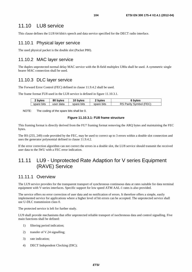
ETSI
ETSI EN 300 175-4 V2.4.1 (2012-04) 104
11.10 LU8 service This clause defines the LU8 64 kbit/s speech and data service specified for the DECT radio interface.
11.10.1 Physical layer service
The used physical packet is the double slot (Packet P80).
11.10.2 MAC layer service
The duplex unprotected normal delay MAC service with the B-field multiplex U80a shall be used. A symmetric single bearer MAC connection shall be used.
11.10.3 DLC layer service
The Forward Error Control (FEC) defined in clause 11.9.4.2 shall be used.
The frame format FU8 used in the LU8 service is defined in figure 11.10.3.1.
2 bytes 80 bytes 10 bytes 2 bytes 6 bytes spare bits user data spare bits spare bits RS Parity Symbol (FEC)
NOTE: The coding of the spare bits shall be 0.
Figure 11.10.3.1: FU8 frame structure
This framing format is directly derived from the FU7 framing format removing the ARQ bytes and maintaining the FEC bytes.
The RS (255, 249) code provided by the FEC, may be used to correct up to 3 errors within a double slot connection and uses the generator polynomial defined in clause 11.9.4.2.
If the error correction algorithm can not correct the errors in a double slot, the LU8 service should transmit the received user data to the IWU with a FEC error indication.
11.11 LU9 - Unprotected Rate Adaption for V series Equipment (RAVE) Service
11.11.1 Overview
The LU9 service provides for the transparent transport of synchronous continuous data at rates suitable for data terminal equipment with V-series interfaces. Specific support for low speed ATM AAL-1 rates is also provided.
The service offers no error correction of user data and no notification of errors. It therefore offers a simple, easily implemented service for applications where a higher level of bit errors can be accepted. The unprotected service shall use U-DLC transmission class 0.
The protected service is left for further study.
LU9 shall provide mechanisms that offer unprotected reliable transport of isochronous data and control signalling. Five main functions shall be defined:
1) filtering period indication;
2) transfer of V.24 signalling;
3) rate indication;
4) DECT Independent Clocking (DIC);
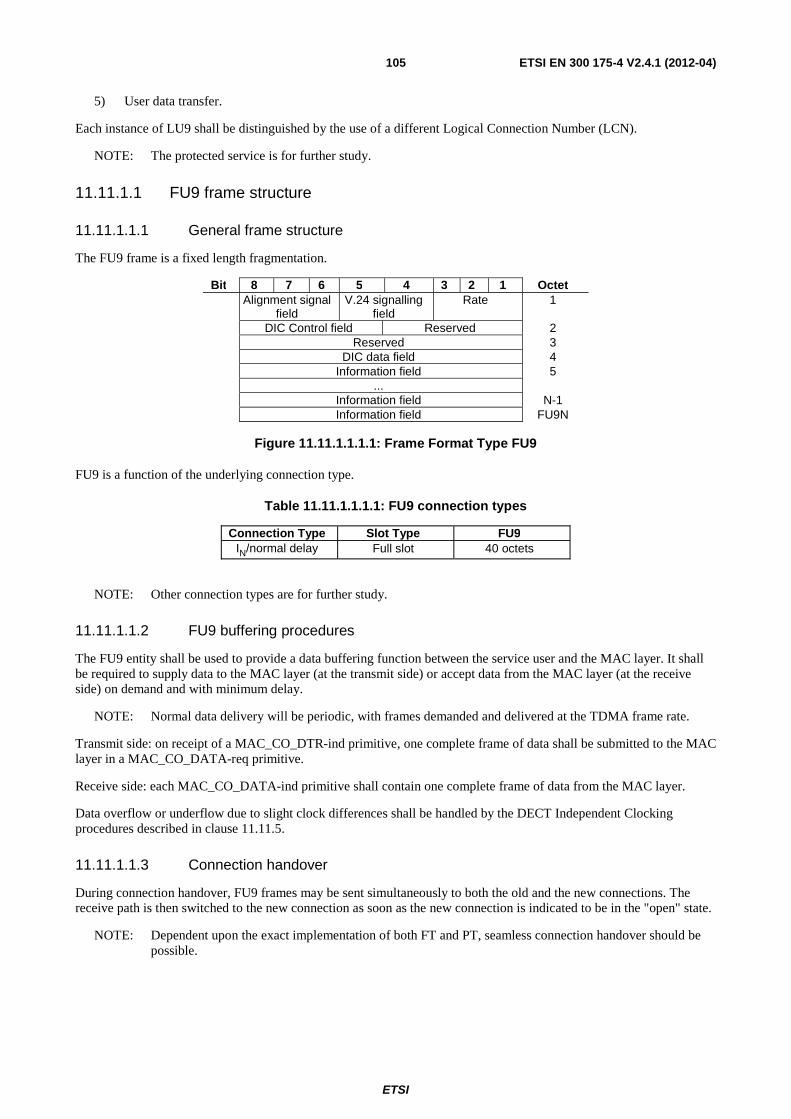
ETSI
ETSI EN 300 175-4 V2.4.1 (2012-04) 105
5) User data transfer.
Each instance of LU9 shall be distinguished by the use of a different Logical Connection Number (LCN).
NOTE: The protected service is for further study.
11.11.1.1 FU9 frame structure
11.11.1.1.1 General frame structure
The FU9 frame is a fixed length fragmentation.
Bit 8 7 6 5 4 3 2 1 Octet Alignment signal
field V.24 signalling
field Rate 1
DIC Control field Reserved 2 Reserved 3 DIC data field 4 Information field 5 ... Information field N-1 Information field FU9N
Figure 11.11.1.1.1.1: Frame Format Type FU9
FU9 is a function of the underlying connection type.
Table 11.11.1.1.1.1: FU9 connection types
Connection Type Slot Type FU9 IN/normal delay Full slot 40 octets
NOTE: Other connection types are for further study.
11.11.1.1.2 FU9 buffering procedures
The FU9 entity shall be used to provide a data buffering function between the service user and the MAC layer. It shall be required to supply data to the MAC layer (at the transmit side) or accept data from the MAC layer (at the receive side) on demand and with minimum delay.
NOTE: Normal data delivery will be periodic, with frames demanded and delivered at the TDMA frame rate.
Transmit side: on receipt of a MAC_CO_DTR-ind primitive, one complete frame of data shall be submitted to the MAC layer in a MAC_CO_DATA-req primitive.
Receive side: each MAC_CO_DATA-ind primitive shall contain one complete frame of data from the MAC layer.
Data overflow or underflow due to slight clock differences shall be handled by the DECT Independent Clocking procedures described in clause 11.11.5.
11.11.1.1.3 Connection handover
During connection handover, FU9 frames may be sent simultaneously to both the old and the new connections. The receive path is then switched to the new connection as soon as the new connection is indicated to be in the "open" state.
NOTE: Dependent upon the exact implementation of both FT and PT, seamless connection handover should be possible.
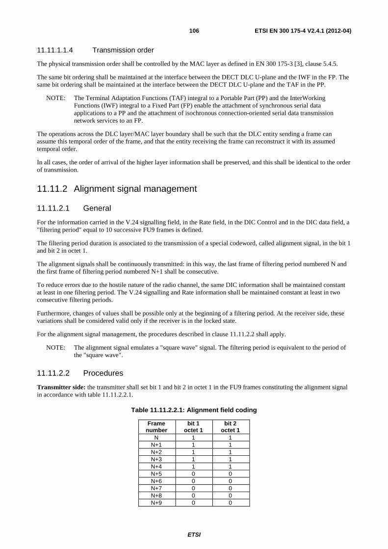
ETSI
ETSI EN 300 175-4 V2.4.1 (2012-04) 106
11.11.1.1.4 Transmission order
The physical transmission order shall be controlled by the MAC layer as defined in EN 300 175-3 [3], clause 5.4.5.
The same bit ordering shall be maintained at the interface between the DECT DLC U-plane and the IWF in the FP. The same bit ordering shall be maintained at the interface between the DECT DLC U-plane and the TAF in the PP.
NOTE: The Terminal Adaptation Functions (TAF) integral to a Portable Part (PP) and the InterWorking Functions (IWF) integral to a Fixed Part (FP) enable the attachment of synchronous serial data applications to a PP and the attachment of isochronous connection-oriented serial data transmission network services to an FP.
The operations across the DLC layer/MAC layer boundary shall be such that the DLC entity sending a frame can assume this temporal order of the frame, and that the entity receiving the frame can reconstruct it with its assumed temporal order.
In all cases, the order of arrival of the higher layer information shall be preserved, and this shall be identical to the order of transmission.
11.11.2 Alignment signal management
11.11.2.1 General
For the information carried in the V.24 signalling field, in the Rate field, in the DIC Control and in the DIC data field, a "filtering period" equal to 10 successive FU9 frames is defined.
The filtering period duration is associated to the transmission of a special codeword, called alignment signal, in the bit 1 and bit 2 in octet 1.
The alignment signals shall be continuously transmitted: in this way, the last frame of filtering period numbered N and the first frame of filtering period numbered N+1 shall be consecutive.
To reduce errors due to the hostile nature of the radio channel, the same DIC information shall be maintained constant at least in one filtering period. The V.24 signalling and Rate information shall be maintained constant at least in two consecutive filtering periods.
Furthermore, changes of values shall be possible only at the beginning of a filtering period. At the receiver side, these variations shall be considered valid only if the receiver is in the locked state.
For the alignment signal management, the procedures described in clause 11.11.2.2 shall apply.
NOTE: The alignment signal emulates a "square wave" signal. The filtering period is equivalent to the period of the "square wave".
11.11.2.2 Procedures
Transmitter side: the transmitter shall set bit 1 and bit 2 in octet 1 in the FU9 frames constituting the alignment signal in accordance with table 11.11.2.2.1.
Table 11.11.2.2.1: Alignment field coding
Frame number
bit 1 octet 1
bit 2 octet 1
N 1 1 N+1 1 1 N+2 1 1 N+3 1 1 N+4 1 1 N+5 0 0 N+6 0 0 N+7 0 0 N+8 0 0 N+9 0 0
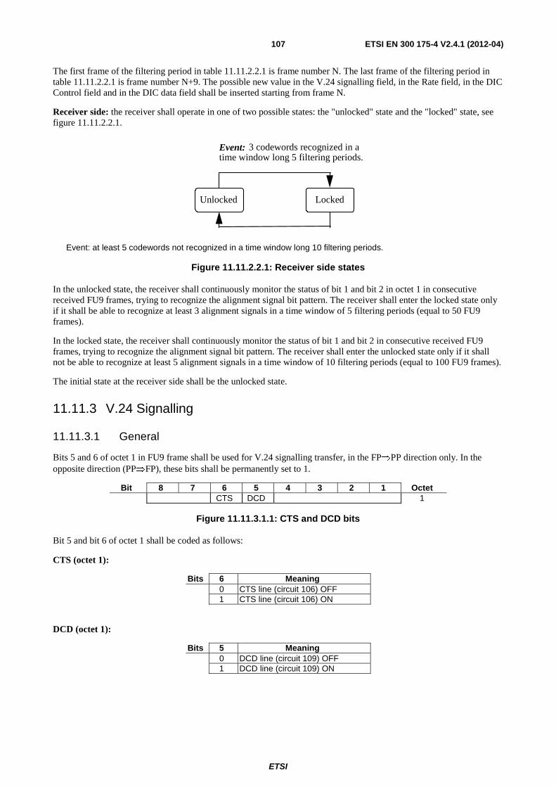
ETSI
ETSI EN 300 175-4 V2.4.1 (2012-04) 107
The first frame of the filtering period in table 11.11.2.2.1 is frame number N. The last frame of the filtering period in table 11.11.2.2.1 is frame number N+9. The possible new value in the V.24 signalling field, in the Rate field, in the DIC Control field and in the DIC data field shall be inserted starting from frame N.
Receiver side: the receiver shall operate in one of two possible states: the "unlocked" state and the "locked" state, see figure 11.11.2.2.1.
Locked Unlocked
Event: 3 codewords recognized in a time window long 5 filtering periods.
Event: at least 5 codewords not recognized in a time window long 10 filtering periods.
Figure 11.11.2.2.1: Receiver side states
In the unlocked state, the receiver shall continuously monitor the status of bit 1 and bit 2 in octet 1 in consecutive received FU9 frames, trying to recognize the alignment signal bit pattern. The receiver shall enter the locked state only if it shall be able to recognize at least 3 alignment signals in a time window of 5 filtering periods (equal to 50 FU9 frames).
In the locked state, the receiver shall continuously monitor the status of bit 1 and bit 2 in consecutive received FU9 frames, trying to recognize the alignment signal bit pattern. The receiver shall enter the unlocked state only if it shall not be able to recognize at least 5 alignment signals in a time window of 10 filtering periods (equal to 100 FU9 frames).
The initial state at the receiver side shall be the unlocked state.
11.11.3 V.24 Signalling
11.11.3.1 General
Bits 5 and 6 of octet 1 in FU9 frame shall be used for V.24 signalling transfer, in the FP⇒PP direction only. In the opposite direction (PP⇒FP), these bits shall be permanently set to 1.
Bit 8 7 6 5 4 3 2 1 Octet CTS DCD 1
Figure 11.11.3.1.1: CTS and DCD bits
Bit 5 and bit 6 of octet 1 shall be coded as follows:
CTS (octet 1):
Bits 6 Meaning 0 CTS line (circuit 106) OFF 1 CTS line (circuit 106) ON
DCD (octet 1):
Bits 5 Meaning 0 DCD line (circuit 109) OFF 1 DCD line (circuit 109) ON
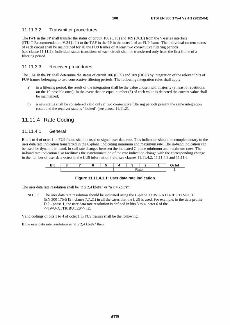
ETSI
ETSI EN 300 175-4 V2.4.1 (2012-04) 108
11.11.3.2 Transmitter procedures
The IWF in the FP shall transfer the status of circuit 106 (CTS) and 109 (DCD) from the V-series interface (ITU-T Recommendation V.24 [i.4]) to the TAF in the PP in the octet 1 of an FU9 frame. The individual current status of each circuit shall be maintained for all the FU9 frames of at least two consecutive filtering periods (see clause 11.11.2). Individual status transitions of each circuit shall be transferred only from the first frame of a filtering period.
11.11.3.3 Receiver procedures
The TAF in the PP shall determine the status of circuit 106 (CTS) and 109 (DCD) by integration of the relevant bits of FU9 frames belonging to two consecutive filtering periods. The following integration rules shall apply:
a) in a filtering period, the result of the integration shall be the value chosen with majority (at least 6 repetitions on the 10 possible ones); In the event that an equal number (5) of each value is detected the current value shall be maintained;
b) a new status shall be considered valid only if two consecutive filtering periods present the same integration result and the receiver state is "locked" (see clause 11.11.2).
11.11.4 Rate Coding
11.11.4.1 General
Bits 1 to 4 of octet 1 in FU9 frame shall be used to signal user data rate. This indication should be complementary to the user data rate indication transferred in the C-plane, indicating minimum and maximum rate. The in-band indication can be used for dynamic in-band, in-call rate changes between the indicated C-plane minimum and maximum rates. The in-band rate indication also facilitates the synchronization of the rate indication change with the corresponding change in the number of user data octets in the LU9 information field, see clauses 11.11.4.2, 11.11.4.3 and 11.11.6.
Bit 8 7 6 5 4 3 2 1 Octet Rate 1
Figure 11.11.4.1.1: User data rate indication
The user data rate resolution shall be "n x 2,4 kbit/s" or "n x 4 kbit/s".
NOTE: The user data rate resolution should be indicated using the C-plane <<IWU-ATTRIBUTES>> IE (EN 300 175-5 [5], clause 7.7.21) in all the cases that the LU9 is used. For example, in the data profile D.2 - phase 1, the user data rate resolution is defined in bits 3 to 4, octet 6 of the <<IWU-ATTRIBUTES>> IE.
Valid codings of bits 1 to 4 of octet 1 in FU9 frames shall be the following:
If the user data rate resolution is "n x 2,4 kbit/s" then:
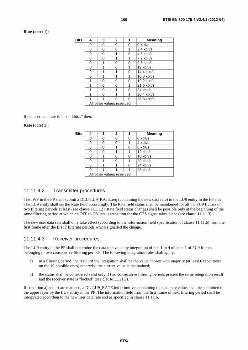
ETSI
ETSI EN 300 175-4 V2.4.1 (2012-04) 109
Rate (octet 1):
Bits 4 3 2 1 Meaning 0 0 0 0 0 kbit/s 0 0 0 1 2,4 kbit/s 0 0 1 0 4,8 kbit/s 0 0 1 1 7,2 kbit/s 0 1 0 0 9,6 kbit/s 0 1 0 1 12 kbit/s 0 1 1 0 14,4 kbit/s 0 1 1 1 16,8 kbit/s 1 0 0 0 19,2 kbit/s 1 0 0 1 21,6 kbit/s 1 0 1 0 24 kbit/s 1 0 1 1 26,4 kbit/s 1 1 0 0 28,8 kbit/s All other values reserved
If the user data rate is "n x 4 kbit/s" then:
Rate (octet 1):
Bits 4 3 2 1 Meaning 0 0 0 0 0 kbit/s 0 0 0 1 4 kbit/s 0 0 1 0 8 kbit/s 0 0 1 1 12 kbit/s 0 1 0 0 16 kbit/s 0 1 0 1 20 kbit/s 0 1 1 0 24 kbit/s 0 1 1 1 28 kbit/s All other values reserved
11.11.4.2 Transmitter procedures
The IWF in the FP shall submit a DLU-LU9_RATE.req (containing the new data rate) to the LU9 entity in the FP side. The LU9 entity shall set the Rate field accordingly. The Rate field status shall be maintained for all the FU9 frames of two filtering periods at least (see clause 11.11.2). Rate field status changes shall be possible only at the beginning of the same filtering period at which an OFF to ON status transition for the CTS signal takes place (see clause 11.11.3).
The new user data rate shall only take effect (according to the information field specification of clause 11.11.6) from the first frame after the first 2 filtering periods which signalled the change.
11.11.4.3 Receiver procedures
The LU9 entity in the PP shall determine the data rate value by integration of bits 1 to 4 of octet 1 of FU9 frames belonging to two consecutive filtering periods. The following integration rules shall apply:
a) in a filtering period, the result of the integration shall be the value chosen with majority (at least 6 repetitions on the 10 possible ones) otherwise the current value is maintained;
b) the status shall be considered valid only if two consecutive filtering periods present the same integration result and the receiver state is "locked" (see clause 11.11.2).
If condition a) and b) are matched, a DL-LU9_RATE.ind primitive, containing the data rate value, shall be submitted to the upper layer by the LU9 entity in the PP. The information field from the first frame of next filtering period shall be interpreted according to the new user data rate and as specified in clause 11.11.6.
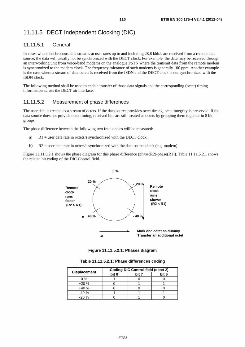
ETSI
ETSI EN 300 175-4 V2.4.1 (2012-04) 110
11.11.5 DECT Independent Clocking (DIC)
11.11.5.1 General
In cases where isochronous data streams at user rates up to and including 28,8 kbit/s are received from a remote data source, the data will usually not be synchronized with the DECT clock. For example, the data may be received through an interworking unit from voice-band modems on the analogue PSTN where the transmit data from the remote modem is synchronized to the modem clock. The frequency tolerance of such modems is generally 100 ppm. Another example is the case where a stream of data octets is received from the ISDN and the DECT clock is not synchronized with the ISDN clock.
The following method shall be used to enable transfer of those data signals and the corresponding (octet) timing information across the DECT air interface.
11.11.5.2 Measurement of phase differences
The user data is treated as a stream of octets. If the data source provides octet timing, octet integrity is preserved. If the data source does not provide octet timing, received bits are still treated as octets by grouping them together in 8 bit groups.
The phase difference between the following two frequencies will be measured:
a) R1 = user data rate in octets/s synchronized with the DECT clock;
b) R2 = user data rate in octets/s synchronized with the data source clock (e.g. modem).
Figure 11.11.5.2.1 shows the phase diagram for this phase difference (phase(R2)-phase(R1)). Table 11.11.5.2.1 shows the related bit coding of the DIC Control field.
Remoteclockrunsslower(R2 < R1)
Remoteclockrunsfaster(R2 > R1)
0 %
- 20 %
- 40 %
Mark one octet as dummyTransfer an additional octet
40 %
20 %
Figure 11.11.5.2.1: Phases diagram
Table 11.11.5.2.1: Phase differences coding
Displacement Coding DIC Control field (octet 2) bit 8 bit 7 bit 6
0 % 1 0 0 +20 % 0 1 1 +40 % 0 0 0 -40 % 1 1 1 -20 % 0 1 0
ETSI
ETSI EN 300 175-4 V2.4.1 (2012-04) 111
11.11.5.3 Compensation control rules
11.11.5.3.1 General
The initial state at both transmitting and receiving state is 0 %. Without compensation, the number of conveyed user data octets per frame is N.
Positive compensation:
On transition from +40 % to -40 %, one frame will convey N+1 user data octets.
(Details: see clause 11.11.5.3.2.)
Negative compensation:
On transition from -40 % to +40 % one frame will convey N-1 user data octets.
(Details: see clause 11.11.5.3.2.)
Hysteresis:
To avoid continuous jitter between neighbouring displacement positions, the displacement code shall be changed only when the measured phase difference is 15 % more or less than the difference indicated by the existing displacement code.
EXAMPLE: Bit combination 011 indicates a phase difference of nominally 20 %. This bit combination will be changed into 000 when the measured phase difference is 35 % or more, and into 100 when the measured phase difference is 5 % or less.
11.11.5.3.2 Optimizing error resilience
Transmission errors may hit the DIC Control field and may therefore cause malfunctioning of the DIC mechanism. In order to optimize resilience against transmission errors the additional rules described in clauses 11.11.5.3.2.1 and 11.11.5.3.2.2 shall apply.
11.11.5.3.2.1 Procedure for conveying state changes
Transmitter rules:
Within one filtering period, the DIC Control fields of all frames shall indicate the same displacement value. As a consequence state changes can only occur once per filtering period.
Only state changes between adjacent states are allowed.
Receiver rules:
At the end of any received filtering period, the receiver shall examine the contents of the DIC Control fields of all frames within that filtering period:
• if at least 6 of the 10 frames included in a filtering period contain the same DIC Control field value, that value is accepted. Otherwise the old state value is maintained;
• if the accepted DIC Control field value indicates a state change to a non adjacent state, the state is chosen which is adjacent and located in the appropriate direction.
11.11.5.3.2.2 Procedure for executing positive and negative compensation
Positive compensation:
The first frame of a filtering period, directly following a filtering period indicating a state change from +40 % to -40 %, shall convey N+1 user data octets, i.e. one octet in the DIC data field, followed by N octets in the user data field.
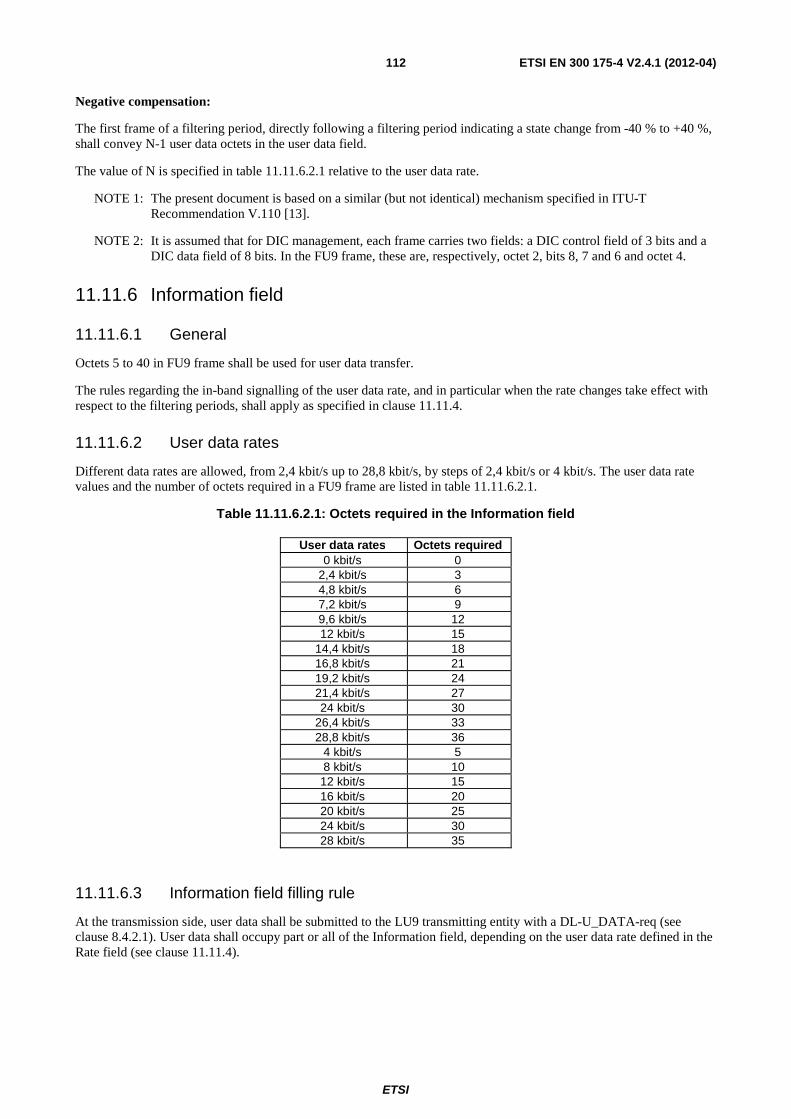
ETSI
ETSI EN 300 175-4 V2.4.1 (2012-04) 112
Negative compensation:
The first frame of a filtering period, directly following a filtering period indicating a state change from -40 % to +40 %, shall convey N-1 user data octets in the user data field.
The value of N is specified in table 11.11.6.2.1 relative to the user data rate.
NOTE 1: The present document is based on a similar (but not identical) mechanism specified in ITU-T Recommendation V.110 [13].
NOTE 2: It is assumed that for DIC management, each frame carries two fields: a DIC control field of 3 bits and a DIC data field of 8 bits. In the FU9 frame, these are, respectively, octet 2, bits 8, 7 and 6 and octet 4.
11.11.6 Information field
11.11.6.1 General
Octets 5 to 40 in FU9 frame shall be used for user data transfer.
The rules regarding the in-band signalling of the user data rate, and in particular when the rate changes take effect with respect to the filtering periods, shall apply as specified in clause 11.11.4.
11.11.6.2 User data rates
Different data rates are allowed, from 2,4 kbit/s up to 28,8 kbit/s, by steps of 2,4 kbit/s or 4 kbit/s. The user data rate values and the number of octets required in a FU9 frame are listed in table 11.11.6.2.1.
Table 11.11.6.2.1: Octets required in the Information field
User data rates Octets required 0 kbit/s 0
2,4 kbit/s 3 4,8 kbit/s 6 7,2 kbit/s 9 9,6 kbit/s 12 12 kbit/s 15
14,4 kbit/s 18 16,8 kbit/s 21 19,2 kbit/s 24 21,4 kbit/s 27 24 kbit/s 30
26,4 kbit/s 33 28,8 kbit/s 36
4 kbit/s 5 8 kbit/s 10 12 kbit/s 15 16 kbit/s 20 20 kbit/s 25 24 kbit/s 30 28 kbit/s 35
11.11.6.3 Information field filling rule
At the transmission side, user data shall be submitted to the LU9 transmitting entity with a DL-U_DATA-req (see clause 8.4.2.1). User data shall occupy part or all of the Information field, depending on the user data rate defined in the Rate field (see clause 11.11.4).
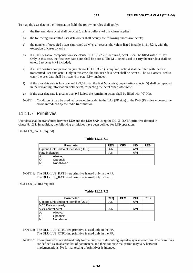
ETSI
ETSI EN 300 175-4 V2.4.1 (2012-04) 113
To map the user data in the Information field, the following rules shall apply:
a) the first user data octet shall be octet 5, unless bullet e) of this clause applies;
b) the following transmitted user data octets shall occupy the following successive octets;
c) the number of occupied octets (indicated as M) shall respect the values listed in table 11.11.6.2.1, with the exception of cases d) and e);
d) if a DIC negative compensation (see clause 11.11.5.3.2.2) is required, octet 5 shall be filled with "0" Hex. Only in this case, the first user data octet shall be octet 6. The M-1 octets used to carry the user data shall be octets 6 to octet M+4 included;
e) if a DIC positive compensation (see clause 11.11.5.3.2.1) is required, octet 4 shall be filled with the first transmitted user data octet. Only in this case, the first user data octet shall be octet 4. The M-1 octets used to carry the user data shall be octets 4 to octet M+4 included;
f) if the user data rate is less or equal to 9,6 kbit/s, the first M octets group (starting at octet 5) shall be repeated in the remaining Information field octets, respecting the octet order; otherwise
g) if the user data rate is greater than 9,6 kbit/s, the remaining octets shall be filled with "0" Hex.
NOTE: Condition f) may be used, at the receiving side, in the TAF (PP side) or the IWF (FP side) to correct the errors introduced by the radio transmission.
11.11.7 Primitives
User data shall be transferred between LU9 and the LU9-SAP using the DL-U_DATA primitive defined in clause 8.4.2.1. In addition, the following primitives have been defined for LU9 operation:
DLU-LU9_RATE{req,ind}
Table 11.11.7.1
Parameter REQ CFM IND RES U-plane Link Endpoint Identifier (ULEI) A/N A/N Rate indication A/N A/N A: Always; O: Optional; N: Not allowed.
NOTE 1: The DLU-LU9_RATE-req primitive is used only in the FP. The DLU-LU9_RATE-ind primitive is used only in the PP.
DLU-LU9_CTRL{req,ind}
Table 11.11.7.2
Parameter REQ CFM IND RES U-plane Link Endpoint Identifier (ULEI) A/N A/N V.24 Data not ready V.24 control octet A/N A/N A: Always; O: Optional; N: Not allowed.
NOTE 2: The DLU-LU9_CTRL-req primitive is used only in the FP. The DLU-LU9_CTRL-ind primitive is used only in the PP.
NOTE 3: These primitives are defined only for the purpose of describing layer-to-layer interactions. The primitives are defined as an abstract list of parameters, and their concrete realization may vary between implementations. No formal testing of primitives is intended.
ETSI
ETSI EN 300 175-4 V2.4.1 (2012-04) 114
11.12 LU10 Enhanced Frame RELay (EFREL) service
11.12.1 General
The LU10 is a general data transmission service for medium data rates, high error correction performance and low complexity. LU10 provides a peer-to-peer connection protocol for an acknowledged exchange of user data within the DLC_U-Layer.
LU10 service is a frame relay service that is accessed through the LU10 SAP.
NOTE 1: Frame Relay service offered by LU10 is similar to the one defined in ITU-T Recommendation I.122 [i.3].
In the case of the 16-level or 64-level modulation option (see EN 300 175-2 [2]) the LU10 service may be used.
The LU10 shall operate on a generic field of user data that shall be transferred into and out of the DLC U-plane as a single SDU. This SDU is assumed to contain one external frame, but the operation of LU10 shall be independent of the actual contents of the SDU.
For LU10 the use of ARQ-type SEL is recommended. Go_Back_N is also allowed.
LU10 shall provide the following functions:
• peer-to-peer transmission of user data (SDUs);
• segmentation of SDUs into PDUs;
• management of the V(S), V(R) state variables(s) and handling of N(s) and N(R) according to the transmission class used;
• multiple SDU transfer, which means that more than one SDU (or only a part of it) can be inserted in one PDU.
LU10 shall not provide the following functions:
• add neither additional header nor checksum to SDUs.
If required, these functions are assumed to be provided by the user of LU10 entity.
LU10 shall provide mechanisms that offer reliable transport of the generic SDUs, and that preserve the SDU boundaries. Depending on the SDU delivery mode, the LU10 service may or may not preserve the order of SDUs, transmitted at one LU10 SAP, when they are delivered at the other end.
NOTE 2: The SAP means the entry to the LU10 entity, refer to clause 11.1.
Two main procedures shall be provided:
1) segmentation of the SDU at the transmitting side, reassembly to SDUs at the receiving side;
2) peer-to-peer transmission of these segments using (small) internal frames.
To avoid possible confusion between external and internal frames the following words are used in this clause from here onwards:
• "SDU" shall refer to the user data;
• "PDU" shall refer to the internal frames;
• "Segment" shall refer to the information content of one "PDU";
• "sub-segment" or "info field" shall refer to the sub-segment of information immediately following a Length indicator octet and with the number of bytes indicated by such indicator.
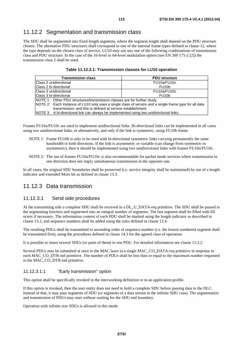
ETSI
ETSI EN 300 175-4 V2.4.1 (2012-04) 115
11.12.2 Segmentation and transmission class
The SDU shall be segmented into fixed length segments, where the segment length shall depend on the PDU structure chosen. The alternative PDU structures shall correspond to one of the internal frame types defined in clause 12, where the type depends on the chosen class of service. LU10 may use any one of the following combinations of transmission class and PDU structure. In the case of the 16-level or 64-level modulation option (see EN 300 175-2 [2]) the transmission class 2 shall be used.
Table 11.12.2.1: Transmission classes for LU10 operation
Transmission class PDU structure Class 2 unidirectional Class 2 bi-directional
FU10a/FU10c FU10b
Class 3 unidirectional Class 3 bi-directional
FU10a/FU10c FU10b
NOTE 1: Other PDU structures/transmission classes are for further study. NOTE 2: Each Instance of LU10 only uses a single class of service and a single frame type for all data
transmission, and this is defined at service establishment. NOTE 3: A bi-directional link can always be implemented using two unidirectional links.
Frames FU10a/FU10c are used to implement unidirectional links. Bi-directional links can be implemented in all cases using two unidirectional links, or alternatively, and only if the link is symmetric, using FU10b frame.
NOTE 1: Frame FU10b is only to be used with bi-directional symmetric links carrying permanently the same bandwidth in both directions. If the link is asymmetric or variable (can change from symmetric to asymmetric), then it should be implemented using two unidirectional links with frames FU10a/FU10c.
NOTE 2: The use of frames FU10a/FU10c is also recommendable for packet mode services where transmission in one direction does not imply simultaneous transmission in the opposite one.
In all cases, the original SDU boundaries shall be preserved (i.e. service integrity shall be maintained) by use of a length indicator and extended More bit as defined in clause 13.3.
11.12.3 Data transmission
11.12.3.1 Send side procedures
At the transmitting side a complete SDU shall be received in a DL_U_DATA-req primitive. The SDU shall be passed to the segmenting function and segmented into an integral number of segments. The last segment shall be filled with fill octets if necessary. The information content of each PDU shall be marked using the length indicator as described in clause 13.3, and sequence numbers shall be added using the rules defined in clause 13.4.
The resulting PDUs shall be transmitted in ascending order of sequence number (i.e. the lowest numbered segment shall be transmitted first), using the procedures defined in clause 14.3 for the agreed class of operation.
It is possible to insert several SDUs (or parts of them) in one PDU. For detailed information see clause 13.3.2.
Several PDUs may be submitted at once to the MAC layer in a single MAC_CO_DATA-req primitive in response to each MAC_CO_DTR-ind primitive. The number of PDUs shall be less than or equal to the maximum number requested in the MAC_CO_DTR-ind primitive.
11.12.3.1.1 "Early transmission" option
This option shall be specifically invoked in the interworking definition or in an application profile.
If this option is invoked, then the user entity does not need to hold a complete SDU before passing data to the DLC. Instead of that, it may pass segments of SDU (or segments of a data stream in the infinite SDU case). The segmentation and transmission of PDUs may start without waiting for the SDU end boundary.
Operation with infinite size SDUs is allowed in this mode.
ETSI
ETSI EN 300 175-4 V2.4.1 (2012-04) 116
11.12.3.2 Receive side procedure
Several PDUs may be received from the MAC layer in a single MAC_CO_DATA-ind primitive. The receive side shall re-order the PDUs using the send sequence numbers as defined in clauses 14.2 and 14.3 according to the agreed class of operation. The receive side shall then search for SDU boundaries using the extended more bit as defined in clause 13.3.
A complete SDU shall be assumed to exist when the following conditions are satisfied:
1) two successive boundaries have been identified using the extended More bit (i.e. there are no intermediate boundaries);
2) PDUs have been successfully received for all of the sequence numbers that lie between those boundaries.
Depending on the delivery mode and the state of the sequence of received PDUs, the identified SDU may:
• be immediately passed to the IWU using a DL_U_DATA-ind primitive,
• wait for the possible completion and passing of previous SDUs in the sequence before being passed to the IWU.
The following delivery modes are supported by LU10.
11.12.3.2.1 Standard SDU delivery mode
This is the default mode and shall be used unless any of the others is specifically invoked in the interworking definition or in an application profile.
As soon as a complete SDU is identified as described in clause 11.12.3.2, it shall be passed to the user entity (typically the IWU) using a DL_U_DATA-ind primitive.
The complete SDU identified may be either, in the "In-sequence PDUs pending for delivery" or in the "out-of-sequence PDUs". See clause 14.3.4.2 for definitions.
NOTE: The standard delivery mode may not ensure the order of SDUs transmitted at one LU10 SAP, when they are delivered at the other end. This happens, for instance, with transmission Class 2, when there is one SDU with missing PDUs and the following SDU is completely received before the retransmission of the missing PDU comes. This behaviour is convenient for Internet and LAN Protocols where the possible violation of sequence is irrelevant. If the guarantee of sequence is necessary, the in-sequence SDU delivery mode may be used, or the sequence may be enforced by the Interworking layer. See for instance, DPRS (EN 301 649 [17], clause B.8).
11.12.3.2.2 In-sequence SDU delivery mode
This mode shall be specifically invoked in the interworking definition or in an application profile.
Only the complete SDUs identified in the "In-sequence PDUs pending for delivery" are immediately delivered to the user entity. SDUs identified in the "out-of-sequence" part of the window shall wait for possible reception of previous SDU before delivering. SDUs shall be always delivered in ascending order.
Complete SDU identified in "out-of-sequence" parts of the receiver window may become in-sequence, either by reception of missing PDUs, or by advancing of the window due to timing out (reception of a synchronization message).
NOTE 1: In the last case, there may be an interruption in the SDU sequence, but never a jump back.
NOTE 2: When there is an interruption in the SDU sequence, it is possible to identify a break in sequence, but it is not possible to determine how many SDUs are missing. If a complete control of the sequence is needed, then it is recommended the addition of sequence numbers by the IWU. See for instance DPRS (EN 301 649 [17], clause B.8)
In the case when several complete SDUs are created in the receiver at the same time (in the "In-sequence PDUs pending for delivery"), they shall be delivered in sequence.
NOTE 3: This case may happen by the reception of a retransmitted PDU binding together existing "out-of-sequence" SDUs with the "In-sequence PDUs pending for delivery".
ETSI
ETSI EN 300 175-4 V2.4.1 (2012-04) 117
11.12.3.2.3 PDU-in-sequence delivery mode
This mode shall be specifically invoked in the interworking definition or in an application profile.
In this mode, in-sequence received PDU are immediately delivered to the user entity without waiting for SDU boundaries. This mode is required when infinite size SDUs are used and is advisable with very large size SDUs.
In addition to the data delivery, the DLC shall provide information to the user entity on position of SDU boundaries, and on possible abnormal termination of SDUs. It is up to the user entity how to use these signals.
NOTE: The abnormal termination of SDU may happen either, due to incomplete reception of SDUs, and due to the reception of the abnormal termination signal. See clause 14.3.4.2.6.
11.12.3.2.4 PDU-as-received delivery mode
This mode shall be specifically invoked in the interworking definition or in an application profile.
In this mode, any received PDU is immediately delivered to the user entity without waiting for SDU boundaries, and independently on if the PDU is in or out of sequence.
This mode is compatible with infinite size and very large SDUs.
The DLC shall provide to the user entity information on position of SDU boundaries, on possible abnormal termination of SDUs, and on PDU sequence numbers. In this mode, LU10 is only in charge of the transmission procedure (including acknowledgements and retransmission requests), while the assembling of the SDU has to be performed by the user entity.
11.12.4 SDU boundaries definition
The SDU is intended to be equal to the packets supplied by the user entity of the DLC LU10 service. In most cases the user entity is a protocol Interworking layer (see EN 301 649 [17], annexes B and C). The SDU boundaries shall be placed as indicated in the interworking unit definition.
NOTE: The interworking unit may define SDU boundaries aligned with the higher layer protocol frames, datagrams or packets, may define a segmentation layer, or may add a PAD function.
If no special provision is given in the interworking unit definition, it shall be assumed that the SDU boundaries are aligned with the packet (frame, datagram, message, etc) boundaries of the protocol transported over LU10.
11.12.4.1 Infinite SDU mode
This mode shall be specifically invoked in the interworking definition or in an application profile. Otherwise it is not allowed.
In this mode, it is possible the operation without SDU boundaries at all (as if the data to be transmitted were a continuous stream). The following specific provisions apply:
• All "M" bits are set to "1".
• The "PDU-in-sequence" (clause 11.12.3.2.3) or the "PDU-as-received" (clause 11.12.3.2.4) delivery modes shall be used.
NOTE: Length indicators will generally be coded with the maximum allowed size of the PDU. However, this is not required, and shorted values may be used in order to synchronize transmission. The insertion of the LI with LI="0", M="1" may be used as filling pattern, if needed.
11.13 LU11 service This clause defines the LU11 64 kbit/s bearer service specified for the DECT radio interface, when A and B field are both modulated at 4 level.
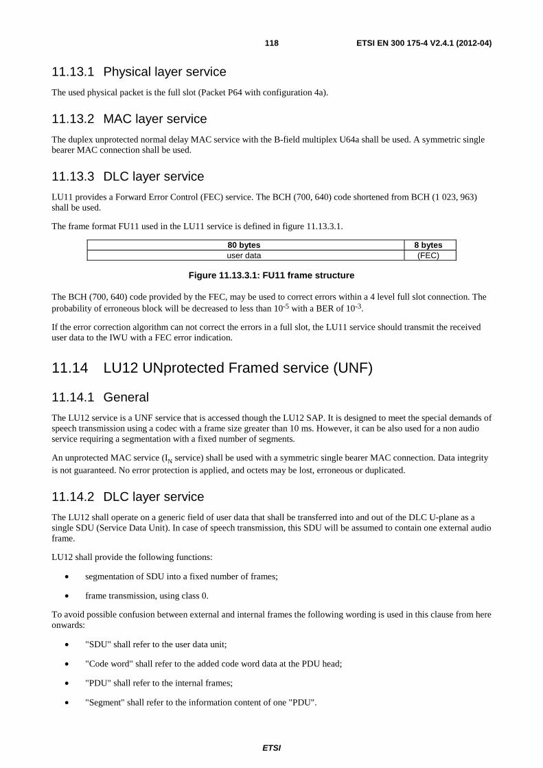
ETSI
ETSI EN 300 175-4 V2.4.1 (2012-04) 118
11.13.1 Physical layer service
The used physical packet is the full slot (Packet P64 with configuration 4a).
11.13.2 MAC layer service
The duplex unprotected normal delay MAC service with the B-field multiplex U64a shall be used. A symmetric single bearer MAC connection shall be used.
11.13.3 DLC layer service
LU11 provides a Forward Error Control (FEC) service. The BCH (700, 640) code shortened from BCH (1 023, 963) shall be used.
The frame format FU11 used in the LU11 service is defined in figure 11.13.3.1.
80 bytes 8 bytes user data (FEC)
Figure 11.13.3.1: FU11 frame structure
The BCH (700, 640) code provided by the FEC, may be used to correct errors within a 4 level full slot connection. The probability of erroneous block will be decreased to less than 10-5 with a BER of 10-3.
If the error correction algorithm can not correct the errors in a full slot, the LU11 service should transmit the received user data to the IWU with a FEC error indication.
11.14 LU12 UNprotected Framed service (UNF)
11.14.1 General
The LU12 service is a UNF service that is accessed though the LU12 SAP. It is designed to meet the special demands of speech transmission using a codec with a frame size greater than 10 ms. However, it can be also used for a non audio service requiring a segmentation with a fixed number of segments.
An unprotected MAC service (IN service) shall be used with a symmetric single bearer MAC connection. Data integrity is not guaranteed. No error protection is applied, and octets may be lost, erroneous or duplicated.
11.14.2 DLC layer service
The LU12 shall operate on a generic field of user data that shall be transferred into and out of the DLC U-plane as a single SDU (Service Data Unit). In case of speech transmission, this SDU will be assumed to contain one external audio frame.
LU12 shall provide the following functions:
• segmentation of SDU into a fixed number of frames;
• frame transmission, using class 0.
To avoid possible confusion between external and internal frames the following wording is used in this clause from here onwards:
• "SDU" shall refer to the user data unit;
• "Code word" shall refer to the added code word data at the PDU head;
• "PDU" shall refer to the internal frames;
• "Segment" shall refer to the information content of one "PDU".
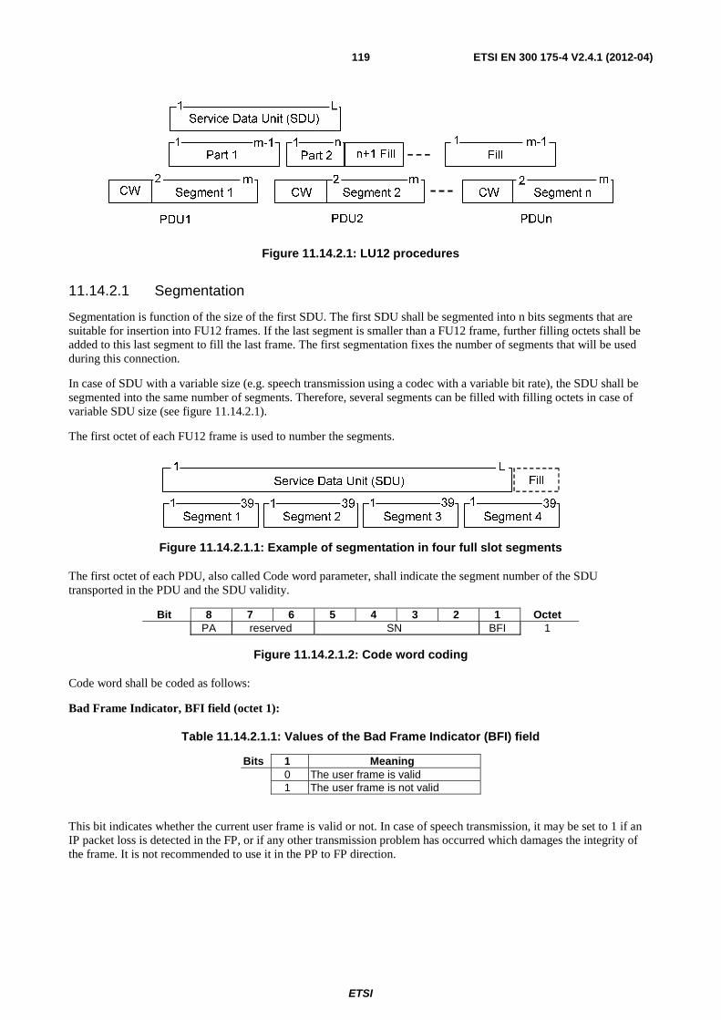
ETSI
ETSI EN 300 175-4 V2.4.1 (2012-04) 119
Figure 11.14.2.1: LU12 procedures
11.14.2.1 Segmentation
Segmentation is function of the size of the first SDU. The first SDU shall be segmented into n bits segments that are suitable for insertion into FU12 frames. If the last segment is smaller than a FU12 frame, further filling octets shall be added to this last segment to fill the last frame. The first segmentation fixes the number of segments that will be used during this connection.
In case of SDU with a variable size (e.g. speech transmission using a codec with a variable bit rate), the SDU shall be segmented into the same number of segments. Therefore, several segments can be filled with filling octets in case of variable SDU size (see figure 11.14.2.1).
The first octet of each FU12 frame is used to number the segments.
Figure 11.14.2.1.1: Example of segmentation in four full slot segments
The first octet of each PDU, also called Code word parameter, shall indicate the segment number of the SDU transported in the PDU and the SDU validity.
Bit 8 7 6 5 4 3 2 1 Octet PA reserved SN BFI 1
Figure 11.14.2.1.2: Code word coding
Code word shall be coded as follows:
Bad Frame Indicator, BFI field (octet 1):
Table 11.14.2.1.1: Values of the Bad Frame Indicator (BFI) field
Bits 1 Meaning 0 The user frame is valid 1 The user frame is not valid
This bit indicates whether the current user frame is valid or not. In case of speech transmission, it may be set to 1 if an IP packet loss is detected in the FP, or if any other transmission problem has occurred which damages the integrity of the frame. It is not recommended to use it in the PP to FP direction.
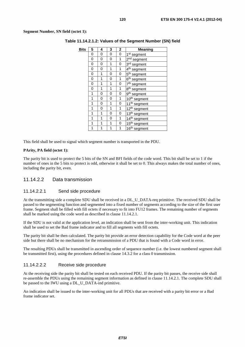
ETSI
ETSI EN 300 175-4 V2.4.1 (2012-04) 120
Segment Number, SN field (octet 1):
Table 11.14.2.1.2: Values of the Segment Number (SN) field
Bits 5 4 3 2 Meaning 0 0 0 0 1st segment 0 0 0 1 2nd segment 0 0 1 0 3rd segment 0 0 1 1 4th segment 0 1 0 0 5th segment 0 1 0 1 6th segment 0 1 1 0 7th segment 0 1 1 1 8th segment 1 0 0 0 9th segment 1 0 0 1 10th segment 1 0 1 0 11th segment 1 0 1 1 12th segment 1 1 0 0 13th segment 1 1 0 1 14th segment 1 1 1 0 15th segment 1 1 1 1 16th segment
This field shall be used to signal which segment number is transported in the PDU.
PArity, PA field (octet 1):
The parity bit is used to protect the 5 bits of the SN and BFI fields of the code word. This bit shall be set to 1 if the number of ones in the 5 bits to protect is odd, otherwise it shall be set to 0. This always makes the total number of ones, including the parity bit, even.
11.14.2.2 Data transmission
11.14.2.2.1 Send side procedure
At the transmitting side a complete SDU shall be received in a DL_U_DATA-req primitive. The received SDU shall be passed to the segmenting function and segmented into a fixed number of segments according to the size of the first user frame. Segment shall be filled with fill octets if necessary to fit into FU12 frames. The remaining number of segments shall be marked using the code word as described in clause 11.14.2.1.
If the SDU is not valid at the application level, an indication shall be sent from the inter-working unit. This indication shall be used to set the Bad frame indicator and to fill all segments with fill octets.
The parity bit shall be then calculated. The parity bit provide an error detection capability for the Code word at the peer side but there shall be no mechanism for the retransmission of a PDU that is found with a Code word in error.
The resulting PDUs shall be transmitted in ascending order of sequence number (i.e. the lowest numbered segment shall be transmitted first), using the procedures defined in clause 14.3.2 for a class 0 transmission.
11.14.2.2.2 Receive side procedure
At the receiving side the parity bit shall be tested on each received PDU. If the parity bit passes, the receive side shall re-assemble the PDUs using the remaining segment information as defined in clause 11.14.2.1. The complete SDU shall be passed to the IWU using a DL_U_DATA-ind primitive.
An indication shall be issued to the inter-working unit for all PDUs that are received with a parity bit error or a Bad frame indicator set.
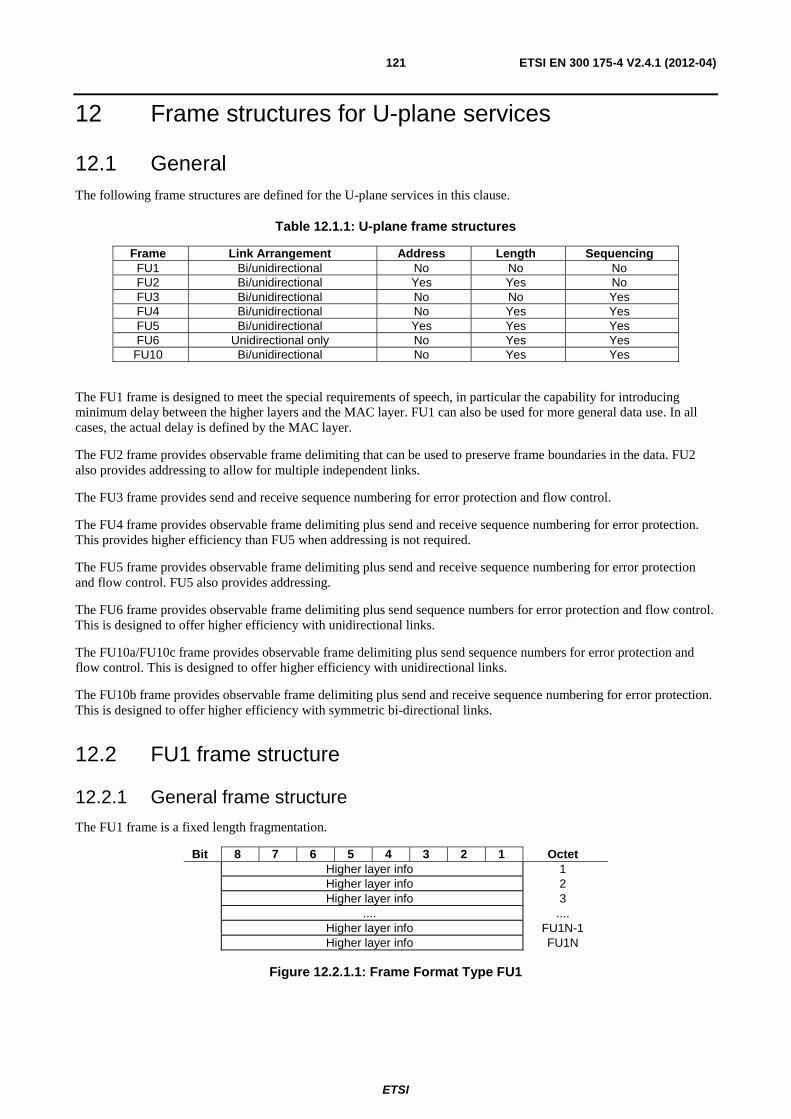
ETSI
ETSI EN 300 175-4 V2.4.1 (2012-04) 121
12 Frame structures for U-plane services
12.1 General The following frame structures are defined for the U-plane services in this clause.
Table 12.1.1: U-plane frame structures
Frame Link Arrangement Address Length Sequencing FU1 Bi/unidirectional No No No FU2 Bi/unidirectional Yes Yes No FU3 Bi/unidirectional No No Yes FU4 Bi/unidirectional No Yes Yes FU5 Bi/unidirectional Yes Yes Yes FU6 Unidirectional only No Yes Yes
FU10 Bi/unidirectional No Yes Yes
The FU1 frame is designed to meet the special requirements of speech, in particular the capability for introducing minimum delay between the higher layers and the MAC layer. FU1 can also be used for more general data use. In all cases, the actual delay is defined by the MAC layer.
The FU2 frame provides observable frame delimiting that can be used to preserve frame boundaries in the data. FU2 also provides addressing to allow for multiple independent links.
The FU3 frame provides send and receive sequence numbering for error protection and flow control.
The FU4 frame provides observable frame delimiting plus send and receive sequence numbering for error protection. This provides higher efficiency than FU5 when addressing is not required.
The FU5 frame provides observable frame delimiting plus send and receive sequence numbering for error protection and flow control. FU5 also provides addressing.
The FU6 frame provides observable frame delimiting plus send sequence numbers for error protection and flow control. This is designed to offer higher efficiency with unidirectional links.
The FU10a/FU10c frame provides observable frame delimiting plus send sequence numbers for error protection and flow control. This is designed to offer higher efficiency with unidirectional links.
The FU10b frame provides observable frame delimiting plus send and receive sequence numbering for error protection. This is designed to offer higher efficiency with symmetric bi-directional links.
12.2 FU1 frame structure
12.2.1 General frame structure
The FU1 frame is a fixed length fragmentation.
Bit 8 7 6 5 4 3 2 1 Octet Higher layer info 1 Higher layer info 2 Higher layer info 3 .... .... Higher layer info FU1N-1 Higher layer info FU1N
Figure 12.2.1.1: Frame Format Type FU1
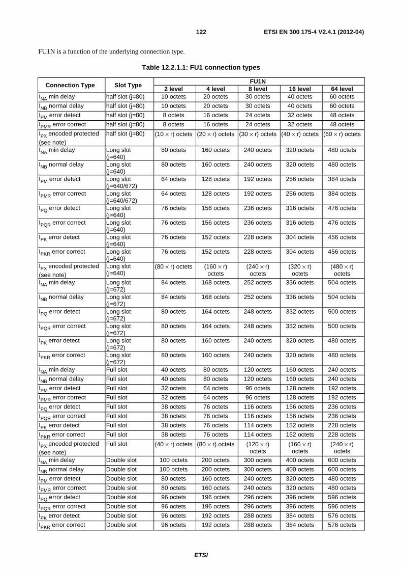
ETSI
ETSI EN 300 175-4 V2.4.1 (2012-04) 122
FU1N is a function of the underlying connection type.
Table 12.2.1.1: FU1 connection types
Connection Type Slot Type FU1N
2 level 4 level 8 level 16 level 64 level INA min delay half slot (j=80) 10 octets 20 octets 30 octets 40 octets 60 octets
INB normal delay half slot (j=80) 10 octets 20 octets 30 octets 40 octets 60 octets
IPM error detect half slot (j=80) 8 octets 16 octets 24 octets 32 octets 48 octets
IPMR error correct half slot (j=80) 8 octets 16 octets 24 octets 32 octets 48 octets
IPX encoded protected
(see note) half slot (j=80) (10 × r) octets (20 × r) octets (30 × r) octets (40 × r) octets (60 × r) octets
INA min delay Long slot (j=640)
80 octets 160 octets 240 octets 320 octets 480 octets
INB normal delay Long slot (j=640)
80 octets 160 octets 240 octets 320 octets 480 octets
IPM error detect Long slot (j=640/672)
64 octets 128 octets 192 octets 256 octets 384 octets
IPMR error correct Long slot (j=640/672)
64 octets 128 octets 192 octets 256 octets 384 octets
IPQ error detect Long slot (j=640)
76 octets 156 octets 236 octets 316 octets 476 octets
IPQR error correct Long slot (j=640)
76 octets 156 octets 236 octets 316 octets 476 octets
IPK error detect Long slot (j=640)
76 octets 152 octets 228 octets 304 octets 456 octets
IPKR error correct Long slot (j=640)
76 octets 152 octets 228 octets 304 octets 456 octets
IPX encoded protected
(see note) Long slot (j=640)
(80 × r) octets (160 × r) octets
(240 × r) octets
(320 × r) octets
(480 × r) octets
INA min delay Long slot (j=672)
84 octets 168 octets 252 octets 336 octets 504 octets
INB normal delay Long slot (j=672)
84 octets 168 octets 252 octets 336 octets 504 octets
IPQ error detect Long slot (j=672)
80 octets 164 octets 248 octets 332 octets 500 octets
IPQR error correct Long slot (j=672)
80 octets 164 octets 248 octets 332 octets 500 octets
IPK error detect Long slot (j=672)
80 octets 160 octets 240 octets 320 octets 480 octets
IPKR error correct Long slot (j=672)
80 octets 160 octets 240 octets 320 octets 480 octets
INA min delay Full slot 40 octets 80 octets 120 octets 160 octets 240 octets
INB normal delay Full slot 40 octets 80 octets 120 octets 160 octets 240 octets
IPM error detect Full slot 32 octets 64 octets 96 octets 128 octets 192 octets
IPMR error correct Full slot 32 octets 64 octets 96 octets 128 octets 192 octets
IPQ error detect Full slot 38 octets 76 octets 116 octets 156 octets 236 octets
IPQR error correct Full slot 38 octets 76 octets 116 octets 156 octets 236 octets
IPK error detect Full slot 38 octets 76 octets 114 octets 152 octets 228 octets
IPKR error correct Full slot 38 octets 76 octets 114 octets 152 octets 228 octets
IPX encoded protected (see note)
Full slot (40 × r) octets (80 × r) octets (120 × r) octets
(160 × r) octets
(240 × r) octets
INA min delay Double slot 100 octets 200 octets 300 octets 400 octets 600 octets
INB normal delay Double slot 100 octets 200 octets 300 octets 400 octets 600 octets
IPM error detect Double slot 80 octets 160 octets 240 octets 320 octets 480 octets
IPMR error correct Double slot 80 octets 160 octets 240 octets 320 octets 480 octets
IPQ error detect Double slot 96 octets 196 octets 296 octets 396 octets 596 octets
IPQR error correct Double slot 96 octets 196 octets 296 octets 396 octets 596 octets
IPK error detect Double slot 96 octets 192 octets 288 octets 384 octets 576 octets
IPKR error correct Double slot 96 octets 192 octets 288 octets 384 octets 576 octets
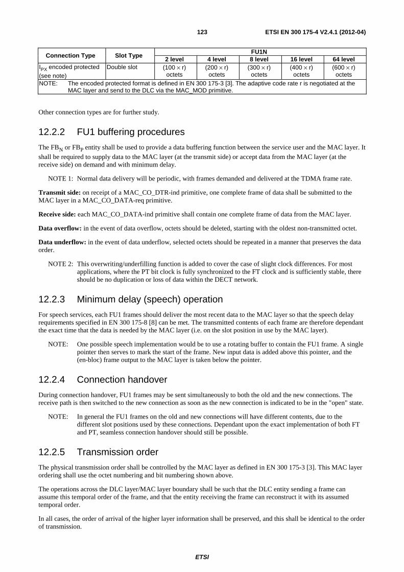
ETSI
ETSI EN 300 175-4 V2.4.1 (2012-04) 123
Connection Type Slot Type FU1N
2 level 4 level 8 level 16 level 64 level IPX encoded protected (see note)
Double slot (100 × r) octets
(200 × r) octets
(300 × r) octets
(400 × r) octets
(600 × r) octets
NOTE: The encoded protected format is defined in EN 300 175-3 [3]. The adaptive code rate r is negotiated at the MAC layer and send to the DLC via the MAC_MOD primitive.
Other connection types are for further study.
12.2.2 FU1 buffering procedures
The FBN or FBP entity shall be used to provide a data buffering function between the service user and the MAC layer. It
shall be required to supply data to the MAC layer (at the transmit side) or accept data from the MAC layer (at the receive side) on demand and with minimum delay.
NOTE 1: Normal data delivery will be periodic, with frames demanded and delivered at the TDMA frame rate.
Transmit side: on receipt of a MAC_CO_DTR-ind primitive, one complete frame of data shall be submitted to the MAC layer in a MAC_CO_DATA-req primitive.
Receive side: each MAC_CO_DATA-ind primitive shall contain one complete frame of data from the MAC layer.
Data overflow: in the event of data overflow, octets should be deleted, starting with the oldest non-transmitted octet.
Data underflow: in the event of data underflow, selected octets should be repeated in a manner that preserves the data order.
NOTE 2: This overwriting/underfilling function is added to cover the case of slight clock differences. For most applications, where the PT bit clock is fully synchronized to the FT clock and is sufficiently stable, there should be no duplication or loss of data within the DECT network.
12.2.3 Minimum delay (speech) operation
For speech services, each FU1 frames should deliver the most recent data to the MAC layer so that the speech delay requirements specified in EN 300 175-8 [8] can be met. The transmitted contents of each frame are therefore dependant the exact time that the data is needed by the MAC layer (i.e. on the slot position in use by the MAC layer).
NOTE: One possible speech implementation would be to use a rotating buffer to contain the FU1 frame. A single pointer then serves to mark the start of the frame. New input data is added above this pointer, and the (en-bloc) frame output to the MAC layer is taken below the pointer.
12.2.4 Connection handover
During connection handover, FU1 frames may be sent simultaneously to both the old and the new connections. The receive path is then switched to the new connection as soon as the new connection is indicated to be in the "open" state.
NOTE: In general the FU1 frames on the old and new connections will have different contents, due to the different slot positions used by these connections. Dependant upon the exact implementation of both FT and PT, seamless connection handover should still be possible.
12.2.5 Transmission order
The physical transmission order shall be controlled by the MAC layer as defined in EN 300 175-3 [3]. This MAC layer ordering shall use the octet numbering and bit numbering shown above.
The operations across the DLC layer/MAC layer boundary shall be such that the DLC entity sending a frame can assume this temporal order of the frame, and that the entity receiving the frame can reconstruct it with its assumed temporal order.
In all cases, the order of arrival of the higher layer information shall be preserved, and this shall be identical to the order of transmission.
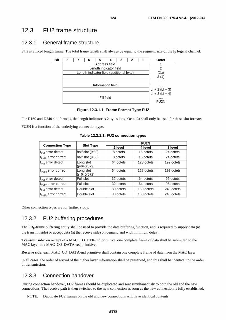
ETSI
ETSI EN 300 175-4 V2.4.1 (2012-04) 124
12.3 FU2 frame structure
12.3.1 General frame structure
FU2 is a fixed length frame. The total frame length shall always be equal to the segment size of the IP logical channel.
Bit 8 7 6 5 4 3 2 1 Octet Address field 1 Length indicator field 2 Length indicator field (additional byte) (2a) 3 (4) .... .... Information field .... LI + 2 (LI + 3) LI + 3 (LI + 4) Fill field .... FU2N
Figure 12.3.1.1: Frame Format Type FU2
For D160 and D240 slot formats, the length indicator is 2 bytes long. Octet 2a shall only be used for these slot formats.
FU2N is a function of the underlying connection type.
Table 12.3.1.1: FU2 connection types
Connection Type Slot Type FU2N
2 level 4 level 8 level IPM error detect half slot (j=80) 8 octets 16 octets 24 octets
IPMR error correct half slot (j=80) 8 octets 16 octets 24 octets
IPM error detect Long slot (j=640/672)
64 octets 128 octets 192 octets
IPMR error correct Long slot (j=640/672)
64 octets 128 octets 192 octets
IPM error detect Full slot 32 octets 64 octets 96 octets
IPMR error correct Full slot 32 octets 64 octets 96 octets
IPM error detect Double slot 80 octets 160 octets 240 octets
IPMR error correct Double slot 80 octets 160 octets 240 octets
Other connection types are for further study.
12.3.2 FU2 buffering procedures
The FBP-frame buffering entity shall be used to provide the data buffering function, and is required to supply data (at the transmit side) or accept data (at the receive side) on demand and with minimum delay.
Transmit side: on receipt of a MAC_CO_DTR-ind primitive, one complete frame of data shall be submitted to the MAC layer in a MAC_CO_DATA-req primitive.
Receive side: each MAC_CO_DATA-ind primitive shall contain one complete frame of data from the MAC layer.
In all cases, the order of arrival of the higher layer information shall be preserved, and this shall be identical to the order of transmission.
12.3.3 Connection handover
During connection handover, FU2 frames should be duplicated and sent simultaneously to both the old and the new connections. The receive path is then switched to the new connection as soon as the new connection is fully established.
NOTE: Duplicate FU2 frames on the old and new connections will have identical contents.
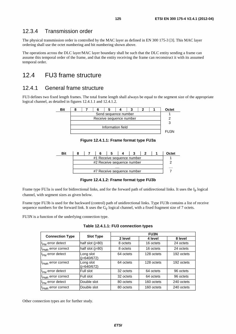
ETSI
ETSI EN 300 175-4 V2.4.1 (2012-04) 125
12.3.4 Transmission order
The physical transmission order is controlled by the MAC layer as defined in EN 300 175-3 [3]. This MAC layer ordering shall use the octet numbering and bit numbering shown above.
The operations across the DLC layer/MAC layer boundary shall be such that the DLC entity sending a frame can assume this temporal order of the frame, and that the entity receiving the frame can reconstruct it with its assumed temporal order.
12.4 FU3 frame structure
12.4.1 General frame structure
FU3 defines two fixed length frames. The total frame length shall always be equal to the segment size of the appropriate logical channel, as detailed in figures 12.4.1.1 and 12.4.1.2.
Bit 8 7 6 5 4 3 2 1 Octet Send sequence number 1 Receive sequence number 2 3 Information field FU3N
Figure 12.4.1.1: Frame format type FU3a
Bit 8 7 6 5 4 3 2 1 Octet
#1 Receive sequence number 1 #2 Receive sequence number 2 .... .... #7 Receive sequence number 7
Figure 12.4.1.2: Frame format type FU3b
Frame type FU3a is used for bidirectional links, and for the forward path of unidirectional links. It uses the IP logical channel, with segment sizes as given below.
Frame type FU3b is used for the backward (control) path of unidirectional links. Type FU3b contains a list of receive sequence numbers for the forward link. It uses the GF logical channel, with a fixed fragment size of 7 octets.
FU3N is a function of the underlying connection type.
Table 12.4.1.1: FU3 connection types
Connection Type Slot Type FU3N
2 level 4 level 8 level IPM error detect half slot (j=80) 8 octets 16 octets 24 octets
IPMR error correct half slot (j=80) 8 octets 16 octets 24 octets
IPM error detect Long slot (j=640/672)
64 octets 128 octets 192 octets
IPMR error correct Long slot (j=640/672)
64 octets 128 octets 192 octets
IPM error detect Full slot 32 octets 64 octets 96 octets
IPMR error correct Full slot 32 octets 64 octets 96 octets
IPM error detect Double slot 80 octets 160 octets 240 octets
IPMR error correct Double slot 80 octets 160 octets 240 octets
Other connection types are for further study.
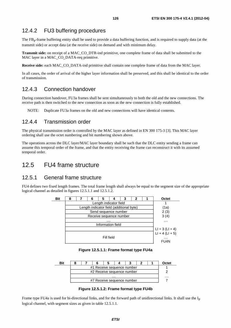
ETSI
ETSI EN 300 175-4 V2.4.1 (2012-04) 126
12.4.2 FU3 buffering procedures
The FBP-frame buffering entity shall be used to provide a data buffering function, and is required to supply data (at the transmit side) or accept data (at the receive side) on demand and with minimum delay.
Transmit side: on receipt of a MAC_CO_DTR-ind primitive, one complete frame of data shall be submitted to the MAC layer in a MAC_CO_DATA-req primitive.
Receive side: each MAC_CO_DATA-ind primitive shall contain one complete frame of data from the MAC layer.
In all cases, the order of arrival of the higher layer information shall be preserved, and this shall be identical to the order of transmission.
12.4.3 Connection handover
During connection handover, FU3a frames shall be sent simultaneously to both the old and the new connections. The receive path is then switched to the new connection as soon as the new connection is fully established.
NOTE: Duplicate FU3a frames on the old and new connections will have identical contents.
12.4.4 Transmission order
The physical transmission order is controlled by the MAC layer as defined in EN 300 175-3 [3]. This MAC layer ordering shall use the octet numbering and bit numbering shown above.
The operations across the DLC layer/MAC layer boundary shall be such that the DLC entity sending a frame can assume this temporal order of the frame, and that the entity receiving the frame can reconstruct it with its assumed temporal order.
12.5 FU4 frame structure
12.5.1 General frame structure
FU4 defines two fixed length frames. The total frame length shall always be equal to the segment size of the appropriate logical channel as detailed in figures 12.5.1.1 and 12.5.1.2.
Bit 8 7 6 5 4 3 2 1 Octet Length indicator field 1 Length indicator field (additional byte) (1a) Send sequence number 2 (3) Receive sequence number 3 (4) .... .... Information field LI + 3 (LI + 4) LI + 4 (LI + 5) Fill field .... FU4N
Figure 12.5.1.1: Frame format type FU4a
Bit 8 7 6 5 4 3 2 1 Octet
#1 Receive sequence number 1 #2 Receive sequence number 2 .... .... #7 Receive sequence number 7
Figure 12.5.1.2: Frame format type FU4b
Frame type FU4a is used for bi-directional links, and for the forward path of unidirectional links. It shall use the IP logical channel, with segment sizes as given in table 12.5.1.1.
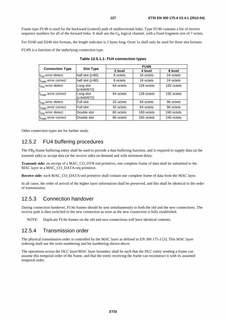
ETSI
ETSI EN 300 175-4 V2.4.1 (2012-04) 127
Frame type FU4b is used for the backward (control) path of unidirectional links. Type FU4b contains a list of receive sequence numbers for all of the forward links. It shall use the GF logical channel, with a fixed fragment size of 7 octets.
For D160 and D240 slot formats, the length indicator is 2 bytes long. Octet 1a shall only be used for these slot formats.
FU4N is a function of the underlying connection type.
Table 12.5.1.1: FU4 connection types
Connection Type Slot Type FU4N
2 level 4 level 8 level IPM error detect half slot (j=80) 8 octets 16 octets 24 octets
IPMR error correct half slot (j=80) 8 octets 16 octets 24 octets
IPM error detect Long slot (j=640/672)
64 octets 128 octets 192 octets
IPMR error correct Long slot (j=640/672)
64 octets 128 octets 192 octets
IPM error detect Full slot 32 octets 64 octets 96 octets
IPMR error correct Full slot 32 octets 64 octets 96 octets
IPM error detect Double slot 80 octets 160 octets 240 octets
IPMR error correct Double slot 80 octets 160 octets 240 octets
Other connection types are for further study.
12.5.2 FU4 buffering procedures
The FBP-frame buffering entity shall be used to provide a data buffering function, and is required to supply data (at the transmit side) or accept data (at the receive side) on demand and with minimum delay.
Transmit side: on receipt of a MAC_CO_DTR-ind primitive, one complete frame of data shall be submitted to the MAC layer in a MAC_CO_DATA-req primitive.
Receive side: each MAC_CO_DATA-ind primitive shall contain one complete frame of data from the MAC layer.
In all cases, the order of arrival of the higher layer information shall be preserved, and this shall be identical to the order of transmission.
12.5.3 Connection handover
During connection handover, FU4a frames should be sent simultaneously to both the old and the new connections. The receive path is then switched to the new connection as soon as the new connection is fully established.
NOTE: Duplicate FU4a frames on the old and new connections will have identical contents.
12.5.4 Transmission order
The physical transmission order is controlled by the MAC layer as defined in EN 300 175-3 [3]. This MAC layer ordering shall use the octet numbering and bit numbering shown above.
The operations across the DLC layer/MAC layer boundary shall be such that the DLC entity sending a frame can assume this temporal order of the frame, and that the entity receiving the frame can reconstruct it with its assumed temporal order.
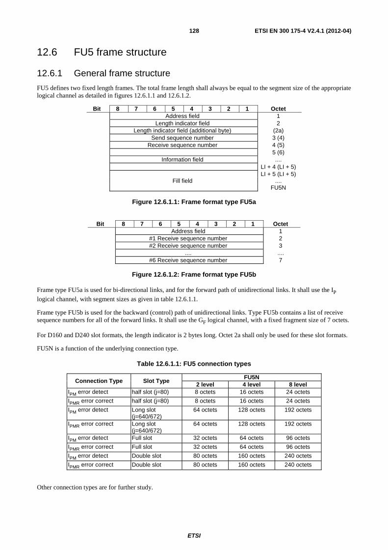
ETSI
ETSI EN 300 175-4 V2.4.1 (2012-04) 128
12.6 FU5 frame structure
12.6.1 General frame structure
FU5 defines two fixed length frames. The total frame length shall always be equal to the segment size of the appropriate logical channel as detailed in figures 12.6.1.1 and 12.6.1.2.
Bit 8 7 6 5 4 3 2 1 Octet Address field 1 Length indicator field 2 Length indicator field (additional byte) (2a) Send sequence number 3 (4) Receive sequence number 4 (5) 5 (6) Information field .... LI + 4 (LI + 5) LI + 5 (LI + 5) Fill field .... FU5N
Figure 12.6.1.1: Frame format type FU5a
Bit 8 7 6 5 4 3 2 1 Octet
Address field 1 #1 Receive sequence number 2 #2 Receive sequence number 3 .... .... #6 Receive sequence number 7
Figure 12.6.1.2: Frame format type FU5b
Frame type FU5a is used for bi-directional links, and for the forward path of unidirectional links. It shall use the IP
logical channel, with segment sizes as given in table 12.6.1.1.
Frame type FU5b is used for the backward (control) path of unidirectional links. Type FU5b contains a list of receive sequence numbers for all of the forward links. It shall use the GF logical channel, with a fixed fragment size of 7 octets.
For D160 and D240 slot formats, the length indicator is 2 bytes long. Octet 2a shall only be used for these slot formats.
FU5N is a function of the underlying connection type.
Table 12.6.1.1: FU5 connection types
Connection Type Slot Type FU5N
2 level 4 level 8 level IPM error detect half slot (j=80) 8 octets 16 octets 24 octets
IPMR error correct half slot (j=80) 8 octets 16 octets 24 octets
IPM error detect Long slot (j=640/672)
64 octets 128 octets 192 octets
IPMR error correct Long slot (j=640/672)
64 octets 128 octets 192 octets
IPM error detect Full slot 32 octets 64 octets 96 octets
IPMR error correct Full slot 32 octets 64 octets 96 octets
IPM error detect Double slot 80 octets 160 octets 240 octets
IPMR error correct Double slot 80 octets 160 octets 240 octets
Other connection types are for further study.
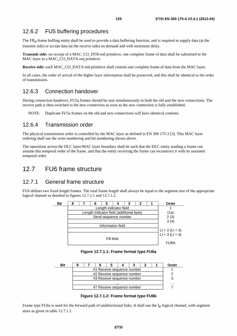
ETSI
ETSI EN 300 175-4 V2.4.1 (2012-04) 129
12.6.2 FU5 buffering procedures
The FBP-frame buffing entity shall be used to provide a data buffering function, and is required to supply data (at the transmit side) or accept data (at the receive side) on demand and with minimum delay.
Transmit side: on receipt of a MAC_CO_DTR-ind primitive, one complete frame of data shall be submitted to the MAC layer in a MAC_CO_DATA-req primitive.
Receive side: each MAC_CO_DATA-ind primitive shall contain one complete frame of data from the MAC layer.
In all cases, the order of arrival of the higher layer information shall be preserved, and this shall be identical to the order of transmission.
12.6.3 Connection handover
During connection handover, FU5a frames should be sent simultaneously to both the old and the new connections. The receive path is then switched to the new connection as soon as the new connection is fully established.
NOTE: Duplicate FU5a frames on the old and new connections will have identical contents.
12.6.4 Transmission order
The physical transmission order is controlled by the MAC layer as defined in EN 300 175-3 [3]. This MAC layer ordering shall use the octet numbering and bit numbering shown above.
The operations across the DLC layer/MAC layer boundary shall be such that the DLC entity sending a frame can assume this temporal order of the frame, and that the entity receiving the frame can reconstruct it with its assumed temporal order.
12.7 FU6 frame structure
12.7.1 General frame structure
FU6 defines two fixed length frames. The total frame length shall always be equal to the segment size of the appropriate logical channel as detailed in figures 12.7.1.1 and 12.7.1.2.
Bit 8 7 6 5 4 3 2 1 Octet Length indicator field 1 Length indicator field (additional byte) (1a) Send sequence number 2 (3) 3 (4) Information field LI + 2 (LI + 3) LI + 3 (LI + 4) Fill field FU6N
Figure 12.7.1.1: Frame format type FU6a
Bit 8 7 6 5 4 3 2 1 Octet
#1 Receive sequence number 1 #2 Receive sequence number 2 #3 Receive sequence number 3 .... .... #7 Receive sequence number 7
Figure 12.7.1.2: Frame format type FU6b
Frame type FU6a is used for the forward path of unidirectional links. It shall use the IP logical channel, with segment sizes as given in table 12.7.1.1.
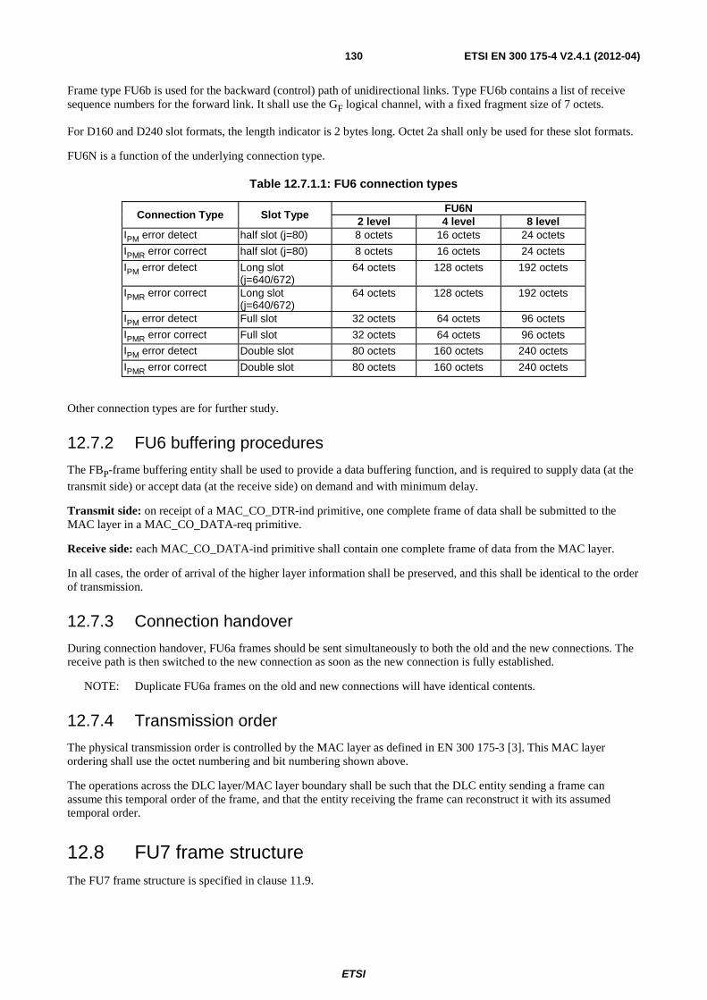
ETSI
ETSI EN 300 175-4 V2.4.1 (2012-04) 130
Frame type FU6b is used for the backward (control) path of unidirectional links. Type FU6b contains a list of receive sequence numbers for the forward link. It shall use the GF logical channel, with a fixed fragment size of 7 octets.
For D160 and D240 slot formats, the length indicator is 2 bytes long. Octet 2a shall only be used for these slot formats.
FU6N is a function of the underlying connection type.
Table 12.7.1.1: FU6 connection types
Connection Type Slot Type FU6N
2 level 4 level 8 level IPM error detect half slot (j=80) 8 octets 16 octets 24 octets
IPMR error correct half slot (j=80) 8 octets 16 octets 24 octets
IPM error detect Long slot (j=640/672)
64 octets 128 octets 192 octets
IPMR error correct Long slot (j=640/672)
64 octets 128 octets 192 octets
IPM error detect Full slot 32 octets 64 octets 96 octets
IPMR error correct Full slot 32 octets 64 octets 96 octets
IPM error detect Double slot 80 octets 160 octets 240 octets
IPMR error correct Double slot 80 octets 160 octets 240 octets
Other connection types are for further study.
12.7.2 FU6 buffering procedures
The FBP-frame buffering entity shall be used to provide a data buffering function, and is required to supply data (at the transmit side) or accept data (at the receive side) on demand and with minimum delay.
Transmit side: on receipt of a MAC_CO_DTR-ind primitive, one complete frame of data shall be submitted to the MAC layer in a MAC_CO_DATA-req primitive.
Receive side: each MAC_CO_DATA-ind primitive shall contain one complete frame of data from the MAC layer.
In all cases, the order of arrival of the higher layer information shall be preserved, and this shall be identical to the order of transmission.
12.7.3 Connection handover
During connection handover, FU6a frames should be sent simultaneously to both the old and the new connections. The receive path is then switched to the new connection as soon as the new connection is fully established.
NOTE: Duplicate FU6a frames on the old and new connections will have identical contents.
12.7.4 Transmission order
The physical transmission order is controlled by the MAC layer as defined in EN 300 175-3 [3]. This MAC layer ordering shall use the octet numbering and bit numbering shown above.
The operations across the DLC layer/MAC layer boundary shall be such that the DLC entity sending a frame can assume this temporal order of the frame, and that the entity receiving the frame can reconstruct it with its assumed temporal order.
12.8 FU7 frame structure The FU7 frame structure is specified in clause 11.9.
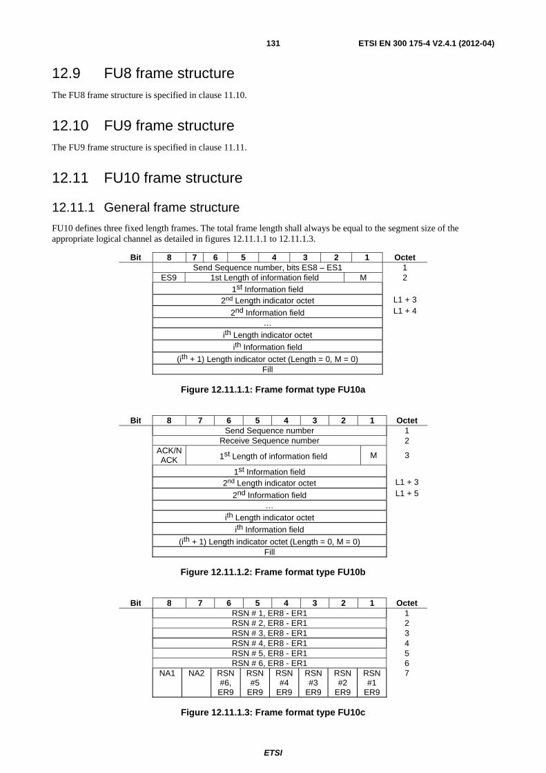
ETSI
ETSI EN 300 175-4 V2.4.1 (2012-04) 131
12.9 FU8 frame structure The FU8 frame structure is specified in clause 11.10.
12.10 FU9 frame structure The FU9 frame structure is specified in clause 11.11.
12.11 FU10 frame structure
12.11.1 General frame structure
FU10 defines three fixed length frames. The total frame length shall always be equal to the segment size of the appropriate logical channel as detailed in figures 12.11.1.1 to 12.11.1.3.
Bit 8 7 6 5 4 3 2 1 Octet Send Sequence number, bits ES8 – ES1 1 ES9 1st Length of information field M 2 1st Information field 2nd Length indicator octet L1 + 3 2nd Information field L1 + 4 … ith Length indicator octet ith Information field (ith + 1) Length indicator octet (Length = 0, M = 0) Fill
Figure 12.11.1.1: Frame format type FU10a
Bit 8 7 6 5 4 3 2 1 Octet Send Sequence number 1 Receive Sequence number 2 ACK/N
ACK 1st Length of information field M 3
1st Information field 2nd Length indicator octet L1 + 3 2nd Information field L1 + 5 … ith Length indicator octet ith Information field (ith + 1) Length indicator octet (Length = 0, M = 0) Fill
Figure 12.11.1.2: Frame format type FU10b
Bit 8 7 6 5 4 3 2 1 Octet RSN # 1, ER8 - ER1 1 RSN # 2, ER8 - ER1 2 RSN # 3, ER8 - ER1 3 RSN # 4, ER8 - ER1 4 RSN # 5, ER8 - ER1 5 RSN # 6, ER8 - ER1 6 NA1 NA2 RSN
#6, ER9
RSN #5
ER9
RSN #4
ER9
RSN #3
ER9
RSN #2
ER9
RSN #1
ER9
7
Figure 12.11.1.3: Frame format type FU10c
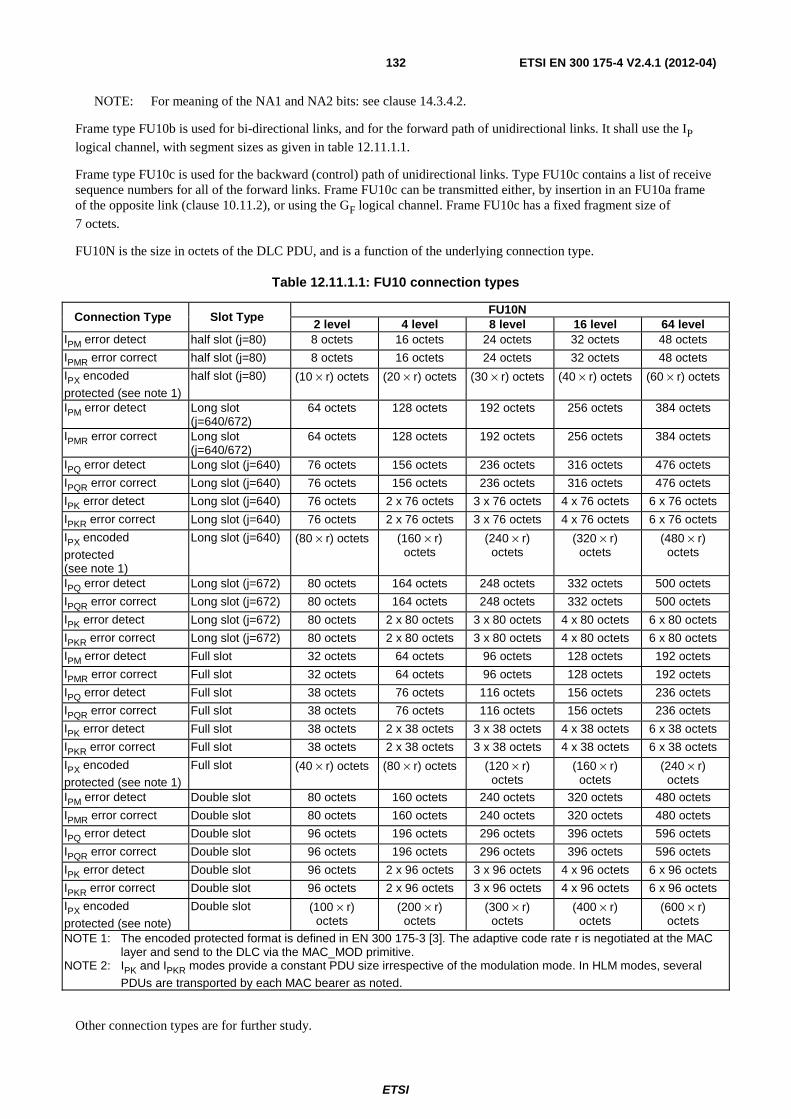
ETSI
ETSI EN 300 175-4 V2.4.1 (2012-04) 132
NOTE: For meaning of the NA1 and NA2 bits: see clause 14.3.4.2.
Frame type FU10b is used for bi-directional links, and for the forward path of unidirectional links. It shall use the IP logical channel, with segment sizes as given in table 12.11.1.1.
Frame type FU10c is used for the backward (control) path of unidirectional links. Type FU10c contains a list of receive sequence numbers for all of the forward links. Frame FU10c can be transmitted either, by insertion in an FU10a frame of the opposite link (clause 10.11.2), or using the GF logical channel. Frame FU10c has a fixed fragment size of 7 octets.
FU10N is the size in octets of the DLC PDU, and is a function of the underlying connection type.
Table 12.11.1.1: FU10 connection types
Connection Type Slot Type FU10N
2 level 4 level 8 level 16 level 64 level IPM error detect half slot (j=80) 8 octets 16 octets 24 octets 32 octets 48 octets
IPMR error correct half slot (j=80) 8 octets 16 octets 24 octets 32 octets 48 octets
IPX encoded
protected (see note 1) half slot (j=80) (10 × r) octets (20 × r) octets (30 × r) octets (40 × r) octets (60 × r) octets
IPM error detect Long slot (j=640/672)
64 octets 128 octets 192 octets 256 octets 384 octets
IPMR error correct Long slot (j=640/672)
64 octets 128 octets 192 octets 256 octets 384 octets
IPQ error detect Long slot (j=640) 76 octets 156 octets 236 octets 316 octets 476 octets
IPQR error correct Long slot (j=640) 76 octets 156 octets 236 octets 316 octets 476 octets
IPK error detect Long slot (j=640) 76 octets 2 x 76 octets 3 x 76 octets 4 x 76 octets 6 x 76 octets
IPKR error correct Long slot (j=640) 76 octets 2 x 76 octets 3 x 76 octets 4 x 76 octets 6 x 76 octets
IPX encoded
protected (see note 1)
Long slot (j=640) (80 × r) octets (160 × r) octets
(240 × r) octets
(320 × r) octets
(480 × r) octets
IPQ error detect Long slot (j=672) 80 octets 164 octets 248 octets 332 octets 500 octets
IPQR error correct Long slot (j=672) 80 octets 164 octets 248 octets 332 octets 500 octets
IPK error detect Long slot (j=672) 80 octets 2 x 80 octets 3 x 80 octets 4 x 80 octets 6 x 80 octets
IPKR error correct Long slot (j=672) 80 octets 2 x 80 octets 3 x 80 octets 4 x 80 octets 6 x 80 octets
IPM error detect Full slot 32 octets 64 octets 96 octets 128 octets 192 octets
IPMR error correct Full slot 32 octets 64 octets 96 octets 128 octets 192 octets
IPQ error detect Full slot 38 octets 76 octets 116 octets 156 octets 236 octets
IPQR error correct Full slot 38 octets 76 octets 116 octets 156 octets 236 octets
IPK error detect Full slot 38 octets 2 x 38 octets 3 x 38 octets 4 x 38 octets 6 x 38 octets
IPKR error correct Full slot 38 octets 2 x 38 octets 3 x 38 octets 4 x 38 octets 6 x 38 octets
IPX encoded
protected (see note 1) Full slot (40 × r) octets (80 × r) octets (120 × r)
octets (160 × r)
octets (240 × r)
octets IPM error detect Double slot 80 octets 160 octets 240 octets 320 octets 480 octets
IPMR error correct Double slot 80 octets 160 octets 240 octets 320 octets 480 octets
IPQ error detect Double slot 96 octets 196 octets 296 octets 396 octets 596 octets
IPQR error correct Double slot 96 octets 196 octets 296 octets 396 octets 596 octets
IPK error detect Double slot 96 octets 2 x 96 octets 3 x 96 octets 4 x 96 octets 6 x 96 octets
IPKR error correct Double slot 96 octets 2 x 96 octets 3 x 96 octets 4 x 96 octets 6 x 96 octets
IPX encoded
protected (see note) Double slot (100 × r)
octets (200 × r)
octets (300 × r)
octets (400 × r)
octets (600 × r)
octets
NOTE 1: The encoded protected format is defined in EN 300 175-3 [3]. The adaptive code rate r is negotiated at the MAC layer and send to the DLC via the MAC_MOD primitive.
NOTE 2: IPK and IPKR modes provide a constant PDU size irrespective of the modulation mode. In HLM modes, several
PDUs are transported by each MAC bearer as noted.
Other connection types are for further study.
ETSI
ETSI EN 300 175-4 V2.4.1 (2012-04) 133
12.11.1.1 Specific for MAC service IPK
When using FU10 over the MAC service IPK (or IPKR) in combination with HLM, several segments, and therefore DLC
frames, are carried by each MAC bearer.
If the number of available frames is lower than the transport capacity, filling frames shall be used to complete the MAC bearer capacity. Such filling frames shall be coded as follows:
• With Length Indicator = 0, and M bit = 0 for the general case when the filling frame is placed in between SDUs. Filling frames shall be padded with the filling pattern.
• With Length Indicator = 0, and M bit = 1, repeated until the end of the frame, for the less usual case when the filling frame is placed in the middle of a SDU.
NOTE 1: The last case is believed to happen only due to limitations in implementation capacity to process the data flow, or to special modes such as "early transmission" option (see clause11.12.3.1.1) combined with slow arrival of data.
• In both cases, there exists the option of inserting frames FU10c in the filling frames using the general mechanism described in clause 12.11.2.1.
NOTE 2: When using FU10 over the MAC service IPKR (error correction variant of IPK) in combination with HLM,
a MAC retransmission may produce unnecessary retransmission of correctly received DLC PDUs.
12.11.2 Transmission of FU10c frames
When using two LU10 unidirectional links (frames FU10a/FU10c) in order to implement a bi-directional service, there is the possibility to send the FU10 frames either, via the dedicated GF channel, or inserting them in a forward FU10a
frame of the opposite link.
NOTE: It is a decision of the FU10c sending side the way of transmission of the frame. The decision can be taken dynamically according to E/U mux selection or free space in FU10a frames.
In both cases, the format of the FU10c frame is identical and is composed of 7 octets as defined in figure 12.11.1.3.
12.11.2.1 Insertion of the FU10c frame in an FU10a frame of the opposite link
One or several FU10c frames can be transmitted at the beginning of an FU10a frame of the opposite link using the following mechanism:
• The first length indicator of the FU10a frame shall contain the special code LI = "63" and M = "1".
• One FU10c frame of seven octets shall be inserted immediately after the length indicator.
• In the following octet there shall be a new Length Indicator. This new Length Indicator could be:
- The same special LI = "63" and M ="1" code indicating that a new FU10c packet is inserted.
- A valid value of LI and M bits indicating the insertion of user data in the FU10a forward channel according to the general FU10a rules.
- The value LI ="0" and M = "0" indicating that there is nothing more in the frame.
NOTE 1: The FU10c frame will be always filled to 7 bytes according to the general FU10c rules.
NOTE 2: After a second insertion of an FU10c, there will be a new length indicator with the same three possibilities. The process can be repeated until the limit indicated in note 3.
NOTE 3: The maximum number of FU10c packets that can be inserted in an FU10a frame is limited to x due to flow control reasons, where x is equal to the number of subfields of the IPM protected format for the slot size and modulation level in use.
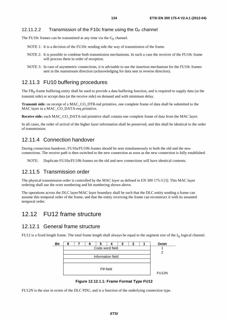
ETSI
ETSI EN 300 175-4 V2.4.1 (2012-04) 134
12.11.2.2 Transmission of the F10c frame using the GF channel
The FU10c frames can be transmitted at any time via the GF channel.
NOTE 1: It is a decision of the FU10c sending side the way of transmission of the frame.
NOTE 2: It is possible to combine both transmission mechanisms. In such a case the receiver of the FU10c frame will process them in order of reception.
NOTE 3: In case of asymmetric connections, it is advisable to use the insertion mechanism for the FU10c frames sent in the mainstream direction (acknowledging for data sent in reverse direction).
12.11.3 FU10 buffering procedures
The FBP-frame buffering entity shall be used to provide a data buffering function, and is required to supply data (at the transmit side) or accept data (at the receive side) on demand and with minimum delay.
Transmit side: on receipt of a MAC_CO_DTR-ind primitive, one complete frame of data shall be submitted to the MAC layer in a MAC_CO_DATA-req primitive.
Receive side: each MAC_CO_DATA-ind primitive shall contain one complete frame of data from the MAC layer.
In all cases, the order of arrival of the higher layer information shall be preserved, and this shall be identical to the order of transmission.
12.11.4 Connection handover
During connection handover, FU10a/FU10b frames should be sent simultaneously to both the old and the new connections. The receive path is then switched to the new connection as soon as the new connection is fully established.
NOTE: Duplicate FU10a/FU10b frames on the old and new connections will have identical contents.
12.11.5 Transmission order
The physical transmission order is controlled by the MAC layer as defined in EN 300 175-3 [3]. This MAC layer ordering shall use the octet numbering and bit numbering shown above.
The operations across the DLC layer/MAC layer boundary shall be such that the DLC entity sending a frame can assume this temporal order of the frame, and that the entity receiving the frame can reconstruct it with its assumed temporal order.
12.12 FU12 frame structure
12.12.1 General frame structure
FU12 is a fixed length frame. The total frame length shall always be equal to the segment size of the IN logical channel.
Bit 8 7 6 5 4 3 2 1 Octet Code word field 1 2 Information field Fill field FU12N
Figure 12.12.1.1: Frame Format Type FU12
FU12N is the size in octets of the DLC PDU, and is a function of the underlying connection type.
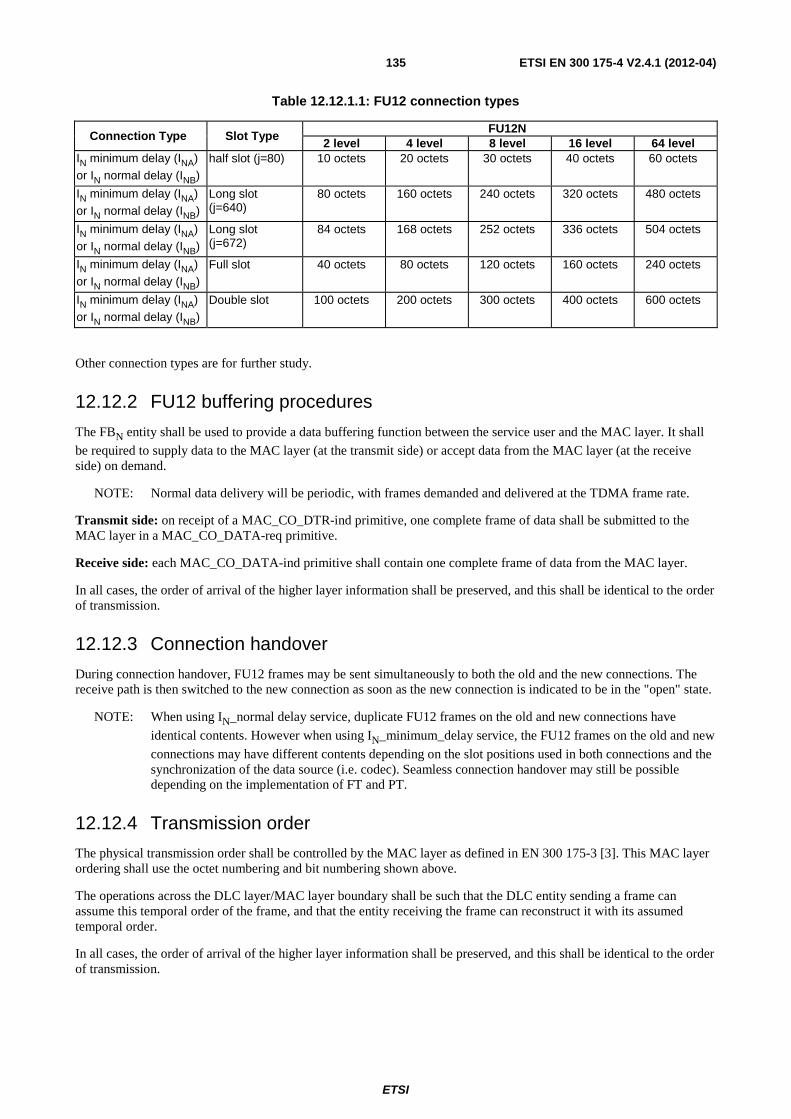
ETSI
ETSI EN 300 175-4 V2.4.1 (2012-04) 135
Table 12.12.1.1: FU12 connection types
Connection Type Slot Type FU12N
2 level 4 level 8 level 16 level 64 level IN minimum delay (INA) or IN normal delay (INB)
half slot (j=80) 10 octets 20 octets 30 octets 40 octets 60 octets
IN minimum delay (INA) or IN normal delay (INB)
Long slot (j=640)
80 octets 160 octets 240 octets 320 octets 480 octets
IN minimum delay (INA) or IN normal delay (INB)
Long slot (j=672)
84 octets 168 octets 252 octets 336 octets 504 octets
IN minimum delay (INA) or IN normal delay (INB)
Full slot 40 octets 80 octets 120 octets 160 octets 240 octets
IN minimum delay (INA) or IN normal delay (INB)
Double slot 100 octets 200 octets 300 octets 400 octets 600 octets
Other connection types are for further study.
12.12.2 FU12 buffering procedures
The FBN entity shall be used to provide a data buffering function between the service user and the MAC layer. It shall be required to supply data to the MAC layer (at the transmit side) or accept data from the MAC layer (at the receive side) on demand.
NOTE: Normal data delivery will be periodic, with frames demanded and delivered at the TDMA frame rate.
Transmit side: on receipt of a MAC_CO_DTR-ind primitive, one complete frame of data shall be submitted to the MAC layer in a MAC_CO_DATA-req primitive.
Receive side: each MAC_CO_DATA-ind primitive shall contain one complete frame of data from the MAC layer.
In all cases, the order of arrival of the higher layer information shall be preserved, and this shall be identical to the order of transmission.
12.12.3 Connection handover
During connection handover, FU12 frames may be sent simultaneously to both the old and the new connections. The receive path is then switched to the new connection as soon as the new connection is indicated to be in the "open" state.
NOTE: When using IN_normal delay service, duplicate FU12 frames on the old and new connections have
identical contents. However when using IN_minimum_delay service, the FU12 frames on the old and new
connections may have different contents depending on the slot positions used in both connections and the synchronization of the data source (i.e. codec). Seamless connection handover may still be possible depending on the implementation of FT and PT.
12.12.4 Transmission order
The physical transmission order shall be controlled by the MAC layer as defined in EN 300 175-3 [3]. This MAC layer ordering shall use the octet numbering and bit numbering shown above.
The operations across the DLC layer/MAC layer boundary shall be such that the DLC entity sending a frame can assume this temporal order of the frame, and that the entity receiving the frame can reconstruct it with its assumed temporal order.
In all cases, the order of arrival of the higher layer information shall be preserved, and this shall be identical to the order of transmission.
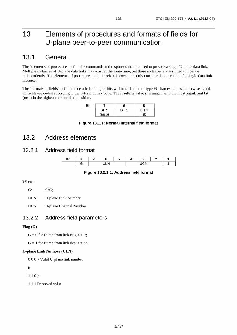
ETSI
ETSI EN 300 175-4 V2.4.1 (2012-04) 136
13 Elements of procedures and formats of fields for U-plane peer-to-peer communication
13.1 General The "elements of procedure" define the commands and responses that are used to provide a single U-plane data link. Multiple instances of U-plane data links may exist at the same time, but these instances are assumed to operate independently. The elements of procedure and their related procedures only consider the operation of a single data link instance.
The "formats of fields" define the detailed coding of bits within each field of type FU frames. Unless otherwise stated, all fields are coded according to the natural binary code. The resulting value is arranged with the most significant bit (msb) in the highest numbered bit position.
Bit 7 6 5 BIT2
(msb) BIT1
BIT0 (lsb)
Figure 13.1.1: Normal internal field format
13.2 Address elements
13.2.1 Address field format
Bit 8 7 6 5 4 3 2 1 G ULN UCN 1
Figure 13.2.1.1: Address field format
Where:
G: flaG;
ULN: U-plane Link Number;
UCN: U-plane Channel Number.
13.2.2 Address field parameters
Flag (G)
G = 0 for frame from link originator;
G = 1 for frame from link destination.
U-plane Link Number (ULN)
0 0 0 } Valid U-plane link number
to
1 1 0 }
1 1 1 Reserved value.
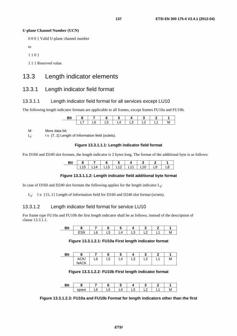
ETSI
ETSI EN 300 175-4 V2.4.1 (2012-04) 137
U-plane Channel Number (UCN)
0 0 0 } Valid U-plane channel number
to
1 1 0 }
1 1 1 Reserved value.
13.3 Length indicator elements
13.3.1 Length indicator field format
13.3.1.1 Length indicator field format for all services except LU10
The following length indicator formats are applicable to all frames, except frames FU10a and FU10b.
Bit 8 7 6 5 4 3 2 1 L7 L6 L5 L4 L3 L2 L1 M
M: More data bit; LI: I ∈ {7..1} Length of Information field (octets).
Figure 13.3.1.1.1: Length indicator field format
For D160 and D240 slot formats, the length indicator is 2 bytes long. The format of the additional byte is as follows:
Bit 8 7 6 5 4 3 2 1 L15 L14 L13 L12 L11 L10 L9 L8
Figure 13.3.1.1.2: Length indicator field additional byte format
In case of D160 and D240 slot formats the following applies for the length indicator LI:
LI: I ∈ {15..1} Length of Information field for D160 and D240 slot format (octets).
13.3.1.2 Length indicator field format for service LU10
For frame type FU10a and FU10b the first length indicator shall be as follows, instead of the description of clause 13.3.1.1.
Bit 8 7 6 5 4 3 2 1 ES9 L6 L5 L4 L3 L2 L1 M
Figure 13.3.1.2.1: FU10a First length indicator format
Bit 8 7 6 5 4 3 2 1 ACK/
NACK L6 L5 L4 L3 L2 L1 M
Figure 13.3.1.2.2: FU10b First length indicator format
Bit 8 7 6 5 4 3 2 1 spare L6 L5 L4 L3 L2 L1 M
Figure 13.3.1.2.3: FU10a and FU10b Format for length indicators other than the first
ETSI
ETSI EN 300 175-4 V2.4.1 (2012-04) 138
In case of frame type FU10a and FU10b the following applies for the length indicator LI:
LI: I ∈ {6..1} Length of Information field for FU10a and FU10b frame type.
In case of the first length indicator of frame type FU10a the following applies:
• the Send sequence number of the PDU is extended with bitES9 of the 1st length indicator field.
In case of the first length indicator of frame type FU10b the following applies:
• bit 8 of the 1st length indicator field is used to indicate ACK/NACK relative to the received sequence number field.
In case of length indicator other that the first one, the following applies:
• the bit 8 (MSB) shall be ignored by the receiver. It shall be coded by the transmitter with "0".
NOTE: The possible coding of this bit to "1" is reserved for further evolution of the standard.
13.3.2 Length indicator field parameters
13.3.2.1 Length indicator field parameters for all services except LU10
The following specific conventions shall apply for all frame types except FU10a and FU10b. Extended more data bit M: the extended more data bit, M, is used to indicate segmentation of messages into FUx frames.
M = "1" indicates that the information field only contains part of a message - there is more to follow.
M = "0" indicates one of two things:
a) that the information field contains a complete message, provided that the M bit of the previous frame was also set to "0";
b) that the information field contains the last segment of a message, provided that the M bit of the previous frame was set to "1".
When the M bit is set to "1", the information field should contain the maximum number of octets.
NOTE 1: This rule only recommends that each frame contains the maximum amount of information. However, the LI field always defines the actual length.
Length parameter LI: the length parameter LI consists of 7 bits for all slot formats except for D160 and D240 and
except the FU10 frame format. For D160 and D240 slot formats, the length parameter LI consists of 15 bits. For FU10
the length parameter consists of 6 bits. The length parameter LI defines the length of the information field in all frames.
Allowable values for 2 level modulated full slot formats are:
• 0 to 30 for frame types FU2, and FU6a;
• 0 to 29 for frame type FU4a;
• 0 to 28 for frame types FU5a.
NOTE 2: Maximum value for full slot is 30 octets. 7 bits are allowed for possible double slot D80 operation - 100 octets. For D160 and D240 operation, 7 bits are not enough and hence 2 octets are required for the Length Indicator field.
LI = "0" is used for all frames that contain no higher layer information.
NOTE 3: Frames that contain no higher layer information should not be transmitted.
Remaining (unused) octets shall be filled with the standard fill octet defined in clause 13.5.
ETSI
ETSI EN 300 175-4 V2.4.1 (2012-04) 139
13.3.2.2 Length indicator field parameters for LU10 service
For frame type FU10a and FU10b only, the following specific conventions shall apply.
The length of Information field, - LI: I ∈ {6..1} - of the length indicator shall be understand as follows:
LI = 63 The meaning depends on the value of the more (M) bit (bit 1 in the same octet)
IF M = 0 means that the frame is a synchronization frame for transmission Class 2, as defined in clause 14.3.4.1.1. This combination can only be used in the first length indicator octet.
IF M = 1 means insertion of a FU10c frame for the opposite channel as defined in clause 12.11.2.1. This only applies to FU10a frames.
LI = 62 means that the length indicator byte is followed by a segment of payload of length equal to the maximum payload size that can be transported by the remaining number of octets of the FU10 frame. This code shall not be used if the value of the maximum payload size is lower than 62. In such a case LI shall show the real value of the payload size.
NOTE 1: If the Length indicator octet is the first one, then the number of octets of the payload is as indicated in table 13.3.2.2.1.
LI = 0 The meaning depends on the value of the more (M) bit (bit 1 in the same octet)
IF M = 0 means that there is nothing more in the rest of the PDU that shall be filled with the fill pattern (defined in clause13.5). The Rx side does not need to continue processing the PDU. A new SDU will begin at the next Length indicator with 1≤LI≤62 at the next PDU.
If the previous Length indicator preceding an info field had the M bit = 1, then this Length indicator signals an abnormal termination of an SDU. See clause 14.3.4.1.3.
If the previous Length indicator preceding an info field had the M bit set to "0", the previous SDU terminated normally at the end of the info field, and the special code in the following Length indicator does not have any special meaning regarding last SDU.
NOTE 2: "Previous length indicator preceding an info field" refers to the previous length indicator with 1≤LI≤62 in the PDU sequence. It has not necessarily had to happen in the same PDU.
NOTE 3: Length indicator with the special codes (LI=63, M=1) and (LI=0, M=1) may be in between and are irrelevant for this rule:
IF M = 1 means that there will be a further Length indicator octet in the following byte. This pattern may be repeated as times as needed.
Any other value of LI (0 ≤ LI ≤ 61) means that the length indicator byte is followed by a segment of payload of the length indicated by the length indicator.
If a segment of information of length lower than the maximum payload size and larger than 61 octets needs to be inserted in a PDU, it shall be split in two or more segments of length lower than 61 inserting length indicators bytes between them. The bit "M" shall be set to "1" in all length indicators except the last one, that must be set to "0".
If a segment of information of length equal to the maximum payload size is to be inserted in a PDU, the bit "M" may be set to "0" or "1" depending on if it is the last field of an SDU, or if the SDU continues in next PDU. This applies either if the Length information field (LI) has been coded with the special value 62 or with the real information field length, but equal to the remaining octets of the PDU.
NOTE 4: The value of the maximum payload size that can be transported by the frame depends of the slot type, MAC service and modulation type. The value of the maximum payload size for frame FU10a is indicated in table 13.3.2.2.1.
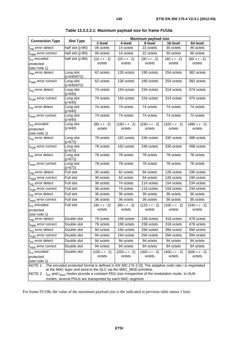
ETSI
ETSI EN 300 175-4 V2.4.1 (2012-04) 140
Table 13.3.2.2.1: Maximum payload size for frame FU10a
Connection Type Slot Type Maximum payload size
2 level 4 level 8 level 16 level 64 level IPM error detect half slot (j=80) 06 octets 14 octets 22 octets 30 octets 46 octets
IPMR error correct half slot (j=80) 06 octets 14 octets 22 octets 30 octets 46 octets
IPX encoded
protected (see note 1)
half slot (j=80) (10 × r - 2) octets
(20 × r - 2) octets
(30 × r - 2) octets
(40 × r - 2) octets
(60 × r - 2) octets
IPM error detect Long slot (j=640/672)
62 octets 126 octets 190 octets 254 octets 382 octets
IPMR error correct Long slot (j=640/672)
62 octets 126 octets 190 octets 254 octets 382 octets
IPQ error detect Long slot (j=640)
74 octets 154 octets 234 octets 314 octets 474 octets
IPQR error correct Long slot (j=640)
74 octets 154 octets 234 octets 314 octets 474 octets
IPK error detect Long slot (j=640)
74 octets 74 octets 74 octets 74 octets 74 octets
IPKR error correct Long slot (j=640)
74 octets 74 octets 74 octets 74 octets 74 octets
IPX encoded
protected (see note 1)
Long slot (j=640)
(80 × r - 2) octets
(160 × r - 2) octets
(240 × r - 2) octets
(320 × r - 2) octets
(480 × r - 2) octets
IPQ error detect Long slot (j=672)
78 octets 162 octets 246 octets 330 octets 498 octets
IPQR error correct Long slot (j=672)
78 octets 162 octets 246 octets 330 octets 498 octets
IPK error detect Long slot (j=672)
78 octets 78 octets 78 octets 78 octets 78 octets
IPKR error correct Long slot (j=672)
78 octets 78 octets 78 octets 78 octets 78 octets
IPM error detect Full slot 30 octets 62 octets 94 octets 126 octets 190 octets
IPMR error correct Full slot 30 octets 62 octets 94 octets 126 octets 190 octets
IPQ error detect Full slot 36 octets 74 octets 114 octets 154 octets 234 octets
IPQR error correct Full slot 36 octets 74 octets 114 octets 154 octets 234 octets
IPK error detect Full slot 36 octets 36 octets 36 octets 36 octets 36 octets
IPKR error correct Full slot 36 octets 36 octets 36 octets 36 octets 36 octets
IPX encoded
protected (see note 1)
Full slot (40 × r - 2) octets
(80 × r - 2) octets
(120 × r - 2) octets
(160 × r - 2) octets
(240 × r - 2) octets
IPM error detect Double slot 78 octets 158 octets 238 octets 318 octets 478 octets
IPMR error correct Double slot 78 octets 158 octets 238 octets 318 octets 478 octets
IPQ error detect Double slot 94 octets 194 octets 294 octets 394 octets 594 octets
IPQR error correct Double slot 94 octets 194 octets 294 octets 394 octets 594 octets
IPK error detect Double slot 94 octets 94 octets 94 octets 94 octets 94 octets
IPKR error correct Double slot 94 octets 94 octets 94 octets 94 octets 94 octets
IPX encoded protected (see note 1)
Double slot (100 × r - 2) octets
(200 × r - 2) octets
(300 × r - 2) octets
(400 × r - 2) octets
(600 × r - 2) octets
NOTE 1: The encoded protected format is defined in EN 300 175-3 [3]. The adaptive code rate r is negotiated at the MAC layer and send to the DLC via the MAC_MOD primitive.
NOTE 2: IPK and IPKR modes provide a constant PDU size irrespective of the modulation mode. In HLM modes, several PDUs are transported by each MAC segment.
For frame FU10b, the value of the maximum payload size is the indicated in previous table minus 1 byte.
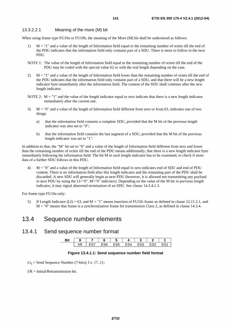
ETSI
ETSI EN 300 175-4 V2.4.1 (2012-04) 141
13.3.2.2.1 Meaning of the more (M) bit
When using frame type FU10a or FU10b, the meaning of the More (M) bit shall be understood as follows:
1) M = "1" and a value of the length of Information field equal to the remaining number of octets till the end of the PDU indicates that the information field only contains part of a SDU. There is more to follow in the next PDU.
NOTE 1: The value of the length of Information field equal to the remaining number of octets till the end of the PDU may be coded with the special value 62 or with the real length depending on the case.
2) M = "1" and a value of the length of Information field lower than the remaining number of octets till the end of the PDU indicates that the information field only contains part of a SDU, and that there will be a new length indicator byte immediately after the information field. The content of the SDU shall continue after the new length indicator.
NOTE 2: M = "1" and the value of the length indicator equal to zero indicate that there is a new length indicator immediately after the current one.
3) M = "0" and a value of the length of Information field different from zero or from 63, indicates one of two things:
a) that the information field contains a complete SDU, provided that the M bit of the previous length indicator was also set to "0";
b) that the information field contains the last segment of a SDU, provided that the M bit of the previous length indicator was set to "1".
In addition to that, the "M" bit set to "0" and a value of the length of Information field different from zero and lower than the remaining number of octets till the end of the PDU means additionally, that there is a new length indicator byte immediately following the information field. The bit M in such length indicator has to be examined, to check if more data of a further SDU follows in this PDU.
4) M = "0" and a value of the length of Information field equal to zero indicates end of SDU and end of PDU content. There is no information field after this length indicator and the remaining part of the PDU shall be discarded. A new SDU will generally begin at next PDU (however, it is allowed not transmitting any payload in next PDU by using the LI="0", M="0" indicator). Depending on the value of the M bit in previous length indicator, it may signal abnormal termination of an SDU. See clause 14.3.4.1.3.
For frame type FU10a only:
5) If Length Indicator (LI) = 63, and M = "1" means insertion of FU10c frame as defined in clause 12.11.2.1, and M = "0" means that frame is a synchronization frame for transmission Class 2, as defined in clause 14.3.4.
13.4 Sequence number elements
13.4.1 Send sequence number format
Bit 8 7 6 5 4 3 2 1 I/R ES7 ES6 ES5 ES4 ES3 ES2 ES1
Figure 13.4.1.1: Send sequence number field format
ESI = Send Sequence Number (7-bits); I ∈ {7..1};
I/R = Initial/Retransmission bit.
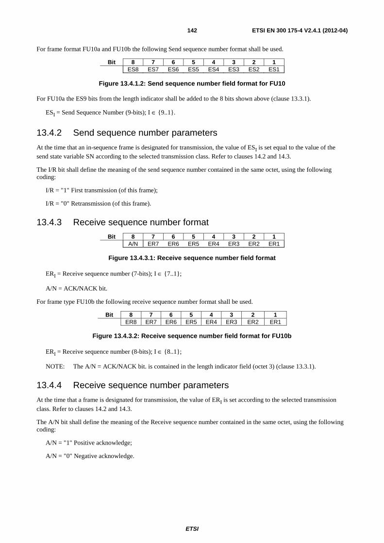
ETSI
ETSI EN 300 175-4 V2.4.1 (2012-04) 142
For frame format FU10a and FU10b the following Send sequence number format shall be used.
Bit 8 7 6 5 4 3 2 1 ES8 ES7 ES6 ES5 ES4 ES3 ES2 ES1
Figure 13.4.1.2: Send sequence number field format for FU10
For FU10a the ES9 bits from the length indicator shall be added to the 8 bits shown above (clause 13.3.1).
ESI = Send Sequence Number (9-bits); I ∈ {9..1}.
13.4.2 Send sequence number parameters
At the time that an in-sequence frame is designated for transmission, the value of ESI is set equal to the value of the send state variable SN according to the selected transmission class. Refer to clauses 14.2 and 14.3.
The I/R bit shall define the meaning of the send sequence number contained in the same octet, using the following coding:
I/R = "1" First transmission (of this frame);
I/R = "0" Retransmission (of this frame).
13.4.3 Receive sequence number format
Bit 8 7 6 5 4 3 2 1 A/N ER7 ER6 ER5 ER4 ER3 ER2 ER1
Figure 13.4.3.1: Receive sequence number field format
ERI = Receive sequence number (7-bits); I ∈ {7..1};
A/N = ACK/NACK bit.
For frame type FU10b the following receive sequence number format shall be used.
Bit 8 7 6 5 4 3 2 1 ER8 ER7 ER6 ER5 ER4 ER3 ER2 ER1
Figure 13.4.3.2: Receive sequence number field format for FU10b
ERI = Receive sequence number (8-bits); I ∈ {8..1};
NOTE: The A/N = ACK/NACK bit. is contained in the length indicator field (octet 3) (clause 13.3.1).
13.4.4 Receive sequence number parameters
At the time that a frame is designated for transmission, the value of ERI is set according to the selected transmission
class. Refer to clauses 14.2 and 14.3.
The A/N bit shall define the meaning of the Receive sequence number contained in the same octet, using the following coding:
A/N = "1" Positive acknowledge;
A/N = "0" Negative acknowledge.
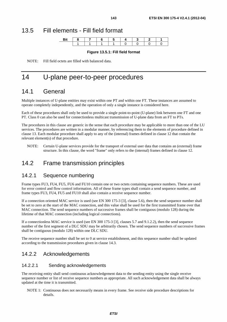
ETSI
ETSI EN 300 175-4 V2.4.1 (2012-04) 143
13.5 Fill elements - Fill field format Bit 8 7 6 5 4 3 2 1
1 1 1 1 0 0 0 0
Figure 13.5.1: Fill field format
NOTE: Fill field octets are filled with balanced data.
14 U-plane peer-to-peer procedures
14.1 General Multiple instances of U-plane entities may exist within one PT and within one FT. These instances are assumed to operate completely independently, and the operation of only a single instance is considered here.
Each of these procedures shall only be used to provide a single point-to-point (U-plane) link between one FT and one PT. Class 0 can also be used for connectionless multicast transmission of U-plane data from an FT to PTs.
The procedures in this clause are generic in the sense that each procedure may be applicable to more than one of the LU services. The procedures are written in a modular manner, by referencing them to the elements of procedure defined in clause 13. Each modular procedure shall apply to any of the (internal) frames defined in clause 12 that contain the relevant element(s) of that procedure.
NOTE: Certain U-plane services provide for the transport of external user data that contains an (external) frame structure. In this clause, the word "frame" only refers to the (internal) frames defined in clause 12.
14.2 Frame transmission principles
14.2.1 Sequence numbering
Frame types FU3, FU4, FU5, FU6 and FU10 contain one or two octets containing sequence numbers. These are used for error control and flow control information. All of these frame types shall contain a send sequence number, and frame types FU3, FU4, FU5 and FU10 shall also contain a receive sequence number.
If a connection oriented MAC service is used (see EN 300 175-3 [3], clause 5.6), then the send sequence number shall be set to zero at the start of the MAC connection, and this value shall be used for the first transmitted frame over that MAC connection. The send sequence numbers of successive frames shall be contiguous (modulo 128) during the lifetime of that MAC connection (including logical connections).
If a connectionless MAC service is used (see EN 300 175-3 [3], clauses 5.7 and 9.1.2.2), then the send sequence number of the first segment of a DLC SDU may be arbitrarily chosen. The send sequence numbers of successive frames shall be contiguous (modulo 128) within one DLC SDU.
The receive sequence number shall be set to 0 at service establishment, and this sequence number shall be updated according to the transmission procedures given in clause 14.3.
14.2.2 Acknowledgements
14.2.2.1 Sending acknowledgements
The receiving entity shall send continuous acknowledgement data to the sending entity using the single receive sequence number or list of receive sequence numbers as appropriate. All such acknowledgement data shall be always updated at the time it is transmitted.
NOTE 1: Continuous does not necessarily means in every frame. See receive side procedure descriptions for details.
ETSI
ETSI EN 300 175-4 V2.4.1 (2012-04) 144
NOTE 2: The sending of acknowledgement data stops when there is no data transmission (see clause 14.3.4.2.2).
14.2.2.2 Receiving acknowledgements
Positive ACKnowledgement information (ACKs) shall only be accepted if it is received within error free frames (see note 1). Negative ACKnowledgement information (NACKs) shall be accepted if it is received within error free frames, but may also be accepted if it is contained in erroneous frames.
Frames that contain multiple acknowledgement octets (multiple RNs) shall contain at least one valid RN. Valid RNs shall be placed in the lowest numbered octets. No RN shall be duplicated. Exception to the previous requirement shall apply to all unused octets that shall be filled with an exact duplicate of the highest RN.
NOTE 1: In unidirectional links, frames that contain multiple acknowledgement octets (e.g. FU6b frames) are transmitted via the GF channel using single B-subfield (see EN 300 175-3 [3]). These frames are to be considered correctly received (i.e. error free frames) if the single B-subfield does not contain errors.
NOTE 2: At the receiving side, the octets in these frames should be processed in ascending order. The remaining octets may then be discarded if a duplication is discovered.
14.2.3 Transmission classes
Four transmission classes are defined:
class 0: no LUx retransmission or sequencing;
class 1: no LUx retransmission (sequencing only);
class 2: variable throughput, limited delay LUx retransmission;
class 3: fixed throughput LUx retransmission.
14.2.3.1 Class 0: No LUX retransmission or sequencing
This service provides a fixed throughput service, with the notification of MAC detected errors. Sequencing shall be provided by the MAC layer, and this shall only be guaranteed if a fixed bandwidth (fixed number of MAC bearers) can be maintained.
This shall use the following MAC I channel operation mode:
IN: minimum_delay;
IN: normal_delay;
IP: error-correct/single bearer only;
IP: error-detect.
NOTE: IP error-correct and IP error-detect services can be used in the multi-subfield (IPM or IPMR) or in the
single-subfield (IPQ or IPQR) variants.
All error detection uses the normal MAC error detection procedures (see EN 300 175-3 [3]).
ETSI
ETSI EN 300 175-4 V2.4.1 (2012-04) 145
14.2.3.2 Class 1: no LUX retransmission
This service provides a variable throughput service, with removal or notification of all errors detected at the MAC layer. The correct frames are always resequenced at the receiver. If a MAC retransmission failure is reported at the sending side (e.g. if the maximum MAC retransmit count is reached) or if a sequence error is detected at the receiving side, the link may be released by the upper layer. In all cases a notification shall be issued to the higher layer whenever an error is detected.
This shall use the following MAC I channel operation mode:
IP: error-correct.
NOTE: IP error-correct service can be used in the multi-subfield (IPMR) or in the single-subfield (IPQR) variants.
All error detection uses the normal MAC error detection procedures (see EN 300 175-3 [3]).
14.2.3.3 Class 2: variable throughput, limited delay LUX retransmission
This service is characterized by the demands of variable throughput with controlled maximum delay. Each frame is retransmitted until acknowledged, or until a timer expired. The DLC retransmission may operate in Go_Back_N or in SELective (SEL) retransmission protocol.
This may use the following MAC I channel operation modes:
IP: error-correct;
IP: error-detect.
NOTE 1: IP error-correct and IP error-detect services can be used in the multi-subfield (IPM or IPMR) or in the
single-subfield (IPQ or IPQR) variants.
All error detection uses the normal MAC error detection procedures (see EN 300 175-3 [3]).
NOTE 2: Care is needed to ensure that the application does not retransmit faster than the DLC retransmission; this could cause the offered throughput to decrease catastrophically.
14.2.3.4 Class 3: fixed throughput LUX retransmission
This service is characterized by the demands of a fixed throughput. Limited error correction based on the retransmission scheme is applied, but data throughput is maintained even in the presence of errors.
This shall use the following MAC I channel operation mode:
IP: error-detect only.
NOTE: IP error-detect service can be used in the multi-subfield (IPM) or in the single-subfield (IPQ) variants.
The potential level of correction is defined by the service attributes, giving a nominal fixed delay, and the excess connection bandwidth available from the MAC layer.
In the event that a frame cannot be delivered correctly within the time limits of the service, both sides of the link shall act independently to clear the old frame.
At the transmitter, any frame that exceeds the specified lifetime (i.e. more than N ms old) is discarded without notification and shall not be retransmitted any more.
The receiver shall independently generate a replacement frame to the output, and shall mark the interruption. The receiver should then proceed as though the frame had been received correctly, including sending positive acknowledgement(s) as appropriate.
ETSI
ETSI EN 300 175-4 V2.4.1 (2012-04) 146
14.2.4 Operation parameter negotiation
Certain operating parameters may be negotiated at call establishment, as defined in EN 300 175-5 [5]. This negotiation shall be optional. The following parameters may be negotiated:
• window sizes;
• transit delay.
Window size negotiation: if negotiation is adopted, the negotiated values shall be used to define the maximum values. If negotiation is not used, the maximum values defined in clause 14.3 shall be used.
Transit delay negotiation: transit delay negotiation shall only be used for class 2 and class 3 operation. If negotiation is adopted, the negotiated values shall be used to define the maximum values for the DLC elements of the delay. If negotiation is not used, the maximum values defined in clause 14.3.5 shall be used.
14.3 Frame transmission procedures
14.3.1 General
The term "SN" shall refer to send Sequence Numbers. The term "RN" shall refer to Receive Sequence numbers.
All operations shall be understood to be Modulo 128 for both send sequence numbers and receive sequence numbers. The term "modulus" shall refer to the value 128.
The procedures shall be described for only one direction of operation, and each procedure shall apply to both bi-directional or unidirectional operation unless otherwise stated. Bi-directional operation shall be assumed to be based on two independent instances of a given procedure; one for each direction.
14.3.2 Class 0 procedures
Class 0 operation does not use any sequence numbers (SN and RN are not used). Class 0 provides a transparent interface to the MAC layer. The MAC layer service should normally provide sequencing (by invoking a constant bandwidth connection) and may optionally provide error protection.
14.3.2.1 Sending side procedure
The sending entity shall submit frames to the MAC layer in the order of arrival. No sequence numbers shall be added, and no retransmission shall be used.
For minimum delay operation (frame type FU1 only) the special buffering procedures described in clause 12.2.3 shall be used.
14.3.2.2 Receiving side procedure
Normal operation: the receiving entity shall deliver frames in the order they are received from the MAC layer. Packets marked as type "unknown" should be discarded. The remaining packets shall be assumed to contain valid frames, and shall be processed in their order of arrival. Frames containing errors (as indicated by the MAC layer) shall nonetheless be delivered to the higher entity, together with the error indication.
Minimum_delay (speech) operation: the receiving entity shall immediately deliver frames in the order they are received from the MAC layer. All packets shall be assumed to contain valid frames, and shall be processed in their order of arrival. Frames indicated as type "unknown" or containing errors (i.e. errors indicated by the MAC layer) shall nonetheless be delivered to the higher entity, together with the error indication.
ETSI
ETSI EN 300 175-4 V2.4.1 (2012-04) 147
14.3.3 Class 1 procedures
Class 1 operation uses both SNs and RNs. If this class is used over a point-to-point link, then both SNs and RNs are used. The RNs then only provide window flow control to avoid possible sequence errors, and shall not invoke any DLC retransmission. Hence, the RNs shall only transport positive acknowledgements (ACKs), denoted by the A/N bit set to 1 (see clause 13.4.3).
If this class is used for connectionless downlink multicast transmission from a FT to PTs, then only SNs are used.
All statements made below in this clause with respect to the use of RNs and windowing only apply to point-to-point links, and are not applicable to connectionless downlink multicast transmission.
14.3.3.1 Sending side procedure
The sending entity shall add SNs to all frames in the order specified by that entity. The I/R bit shall be set to "1".
The resulting frames shall be submitted to the MAC layer in the order of ascending SN.
The sending entity shall maintain a maximum window size between the SN and the last received RN-1. This maximum window size shall be no greater than (modulus-1). A smaller maximum value may be negotiated at call establishment (see clause 14.2.4). A smaller operating window size may be unilaterally adopted by the sending entity at any time.
Due to the modulus operation, each SN may be re-used several times during the life of the link. The minimum interval between re-use shall meet the following requirements:
1) a SN shall not exceed the maximum window size;
2) a SN shall not be re-used within L(S) TDMA frames of the most recent previous use of that number.
The value of L(S) shall be determined by the MAC service used. L(S) shall be equal to the maximum packet lifetime (as defined at service establishment).
Received RNs with the A/N bit set to "1" shall be treated as an acknowledgement for all frames up to and including the frame number RN-1.
Whenever the window size limit is reached further transmissions shall be halted and timer <DLU-01> shall be started. This timer shall be reset whenever a valid RN is received (i.e. an RN that acknowledges one or more outstanding frames). In this case, further transmissions shall be allowed. If timer <DLU-01> expires the link shall be immediately released.
14.3.3.2 Receiving side procedure
The receiving entity shall accept data packets from the MAC layer in any order. Packets marked as type "unknown" and any packets containing errors in the first portion (i.e. errors in the MAC B0 subfield) shall be discarded. The remaining packets shall be assumed to contain valid frames, and shall be processed in their order of arrival.
In-sequence frames are defined as a series of one or more frames that contain no errors and that contain SNs that together form a continuous series of SNs when considered together with other received but undelivered frames. All in-sequence frames shall be immediately delivered to the higher functions.
Out-of-sequence frames are defined as all other frames (i.e. a sequence of one or more frames that do not form a continuous series of SNs or contain some errors). These frames may only be delivered after they have been buffered for at least L(R) TDMA frames after their arrival. During this buffering period, out-of-sequence frames may become in-sequence frames due to the arrival of one or more missing frames. In this event, the frames shall be immediately delivered to the higher layer.
NOTE 1: Out of sequence frames may be discarded before this time limit, in order to limit buffer sizes.
The value of L(R) shall be determined by the MAC service used. For the IP-error-correct services, L(R) shall be equal to or greater than the maximum packet lifetime (as defined at service establishment) and less than (<DLU-01> DIV 2). Hence, for this service, infinite values for the maximum packet lifetime at the MAC layer are not allowed.
NOTE 2: The recommended value for L(R) is equal to the maximum packet lifetime.
ETSI
ETSI EN 300 175-4 V2.4.1 (2012-04) 148
During the buffering period frames may arrive that are duplicates of one or more of the buffered frames. If the original buffered frame was correct, these duplicates shall be discarded. If the original buffered frame contained errors, the duplicate may be used to correct those errors, using selective replacement of erroneous portions (replacement of MAC BN subfields).
NOTE 3: Selective replacement is only performed for frames with the same SN. This requires error free reception of the B0 subfield (i.e. the subfield containing the SN).
If after buffering for L(R) TDMA frames, out-of-sequence frames remain out-of-sequence, the frames shall nonetheless be delivered to higher functions, together with an indication reporting the missing frames. The receiving entity shall then act as though the frames had been received in sequence. In particular, the RN shall be updated to acknowledge acceptance of these frames.
Whenever frames are delivered to the higher functions, the RN shall be set equal to the highest delivered SN + 1.
14.3.4 Class 2 procedures
Class 2 operation uses both SNs and RNs. The RNs provide both window control to avoid possible sequencing errors, and also invoke automatic DLC retransmission. The DLC retransmission may operate in Go_Back_N or in SELective (SEL)retransmission protocol.
14.3.4.1 Sending side procedure
The sending entity shall add SNs to all PDUs to be transmitted in frames in the order specified by that entity.
The PDUs shall be submitted to the MAC layer in the order of ascending SN, taking into account the modulus operation of the sequence numbering.
NOTE 1: Sequence number 0 is higher than sequence number (modulus-1).
NOTE 2: This rule means that retransmissions always have priority relative to first transmissions.
The sending entity shall maintain a maximum window size between the SN and the last received RN. The maximum window size shall be:
• (Modulus-1) when using GbN;
• (Modulus div 2) when using SEL.
A lower maximum value may be negotiated at call establishment (see clause 14.2.4). A smaller operating window size may be unilaterally adopted by the sending entity at any time.
Due to the modulo operation, each SN may be re-used several times during the life of the link. The minimum interval between reuse shall meet the following requirement:
• an SN shall not be reused within L(S) TDMA frames of the most previous use of that number.
The value of L(S) shall be determined by the protocol used:
• using IP-error-correction, L(S) shall be equal to the MAC packet lifetime+1 (as defined at service
establishment);
• using IP-error-detection, L(S) shall be equal to 2.
Whenever the window size limit is reached (thereby halting further transmissions) the sending side shall commence retransmission of all outstanding PDUs not already expired, starting from the oldest unacknowledged PDU. This automatic retransmission shall be stopped whenever a usable RN is received (i.e. a RN that acknowledges one or more outstanding PDUs), and normal transmission or retransmission procedures will be resumed.
Received RN with the A/N bit set to "1" or with NA bits indicating an acknowledge, shall be treated as a positive acknowledgement for all PDUs up to and including the PDU number RN - 1. This positive acknowledgement shall cause an immediate stop to any redundant (unnecessary) retransmissions that may have been scheduled as a result of previously received negative acknowledgements.
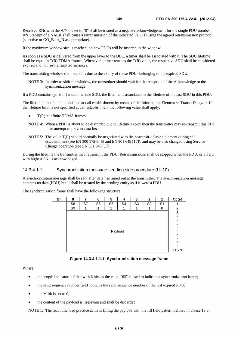
ETSI
ETSI EN 300 175-4 V2.4.1 (2012-04) 149
Received RNs with the A/N bit set to "0" shall be treated as a negative acknowledgement for the single PDU number RN. Receipt of a NACK shall cause a retransmission of the indicated PDU(s) using the agreed retransmission protocol (selective or GO_Back_N as appropriate).
If the maximum window size is reached, no new PDUs will be inserted in the window.
As soon as a SDU is delivered from the upper layer to the DLC, a timer shall be associated with it. The SDU lifetime shall be equal to T(R) TDMA frames. Whenever a timer reaches the T(R) value, the respective SDU shall be considered expired and not (re)transmitted anymore.
The transmitting window shall not shift due to the expiry of those PDUs belonging to the expired SDU.
NOTE 3: In order to shift the window, the transmitter should wait for the reception of the Acknowledge to the synchronization message.
If a PDU contains (parts of) more than one SDU, the lifetime is associated to the lifetime of the last SDU in this PDU.
The lifetime limit should be defined at call establishment by means of the Information Element <<Transit Delay>>. If the lifetime limit is not specified at call establishment the following value shall apply:
• T(R) = infinite TDMA frames.
NOTE 4: When a PDU is about to be discarded due to lifetime expiry then the transmitter may re-transmit this PDU in an attempt to prevent data loss.
NOTE 5: The value T(R) should normally be negotiated with the <<transit-delay>> element during call establishment (see EN 300 175-5 [5] and EN 301 649 [17]), and may be also changed using Service Change operation (see EN 301 649 [17]).
During the lifetime the transmitter may retransmit the PDU. Retransmissions shall be stopped when the PDU, or a PDU with highest SN, is acknowledged.
14.3.4.1.1 Synchronization message sending side procedure (LU10)
A synchronization message shall be sent after data has timed out at the transmitter. The synchronization message contains no data (PDU) but it shall be treated by the sending entity as if it were a PDU.
The synchronization frame shall have the following structure.
Bit 8 7 6 5 4 3 2 1 Octet S8 S7 S6 S5 S4 S3 S2 S1 1 S9 1 1 1 1 1 1 0 2
Payload
3 : : : : : : : :
FUxN
Figure 14.3.4.1.1.1: Synchronization message frame
Where:
• the length indicator is filled with 6 bits as the value "63" is used to indicate a synchronization frame;
• the send sequence number field contains the send sequence number of the last expired PDU;
• the M bit is set to 0;
• the content of the payload is irrelevant and shall be discarded.
NOTE 1: The recommended practice at Tx is filling the payload with the fill field pattern defined in clause 13.5.
ETSI
ETSI EN 300 175-4 V2.4.1 (2012-04) 150
NOTE 2: Length indicator value 63 combined with M bit set to 1 is used for insertion of FU10c frame. See clause 12.11.2.1.
When one or more PDUs expire, then the last expired PDU shall be replaced by the synchronization message. The synchronization message shall contain the sequence number of this PDU.
NOTE 3: Expiry of all PDUs in the transmit window will cause a re-transmit of the synchronization message only, until acknowledge. Then the transmit window can advance and take new PDUs.
Acknowledge of the synchronization message shall use a special synchronization acknowledge to indicate the correct reception of the synchronization message. When the transmitter receives this acknowledge, it knows the receiver has re-synchronized its window and the transmitter is also allowed to move the transmit window forward, accepting new PDUs for transmission.
14.3.4.1.2 Tx side end-of-activity rule
Applicability
This rule applies and is mandatory to support when the following conditions are met:
• DPRS systems operating with any ME Class supporting suspend/resume (ME Class 1, 2 or 3, see EN 301 649 [17]); AND
• DLC U-plane service (LUx) is using transmission Class 2 (clause 14.3.4) and any frame that may carry embedded acknowledgement messages (such as FU10b or FU10a with insertion of FU10c).
NOTE 1: In DPRS ME Class 4 or in non DPRS systems, the application of the rule is optional to the implementer.
Rule
When the following situation is reached:
• There is only one PDU in the transmitter window (only one PDU has been sent after the last received positive ACK); AND
• Such PDU contains only a positive Acknowledgement command (ACK) OR an Acknowledgement command to a Synchronization message.
THEN, such PDU never expires.
NOTE 2: Therefore, a synchronization message will not be sent, as long as such PDU is the only one in transmitter window.
NOTE 3: If further data is received for transmission, then new PDUs will have associated a maximum lifetime and this may cause the sending of a synchronization message as described in clause 14.3.4.1.1.
NOTE 4: This rule, in combination with the Rx rule (see clause 14.3.4.2.2), are in charge of stopping the DLC exchange when there is no user data to be transmitted. The resulting state (one PDU in transmitter window containing only an Acknowledgement message) is one of the two possible stationary states after end of data activity (the other possible state is no PDU in transmitter window).
14.3.4.1.3 Abnormal SDU termination/abort signal (LU10 only)
In a normal transmission of an SDU, the last information sub-segment should be preceded by a Length indicator octet coded with a length of information different from zero and the M bit equal to zero.
The insertion of a Length indicator octet with the codes "Length of information" equal to "0" and M bit equal to "0", when there is an SDU that has not been completely transmitted (previous Length indicator preceding info field transmission had the M bit equal to "1") shall be understood as abnormal termination of the SDU.
The signal means that the transmission of the SDU ends (therefore a new SDU will start after the next Length indicator with 1 ≤ LI ≤ 62, in the next PDU), and that such SDU is incomplete or corrupted.
ETSI
ETSI EN 300 175-4 V2.4.1 (2012-04) 151
The general properties of the LI = "0", M="0" code also apply here. Therefore, the rest of the PDU shall be discarded and the next SDU shall start in the next PDU carting payload (generally the next PDU, however it is possible to leave it blank by using again the (LI ="0", M = "0") code.
The PDU boundaries, or the inclusion of Length indicators without info field, or FU10c frames in between the last SDU sub-segment and the abort signal may happen and do not modify the signal meaning.
NOTE 1: The Length indicator octet with the codes "Length of information" equal to "0" and M bit equal to "0" may be in the same PDU transporting the last info field of the SDU, or in the next one. In the second case, there may be one or several insertions of FU10c frames (with the special code LI = 63, M=1) before the transmission of Length indicator with the SDU abort signal (LI=0, M=0). In both cases there may be Length indicators with LI=0 and M=1.
NOTE 2: The utility of the abort signal is relevant in the cases when similar signals may be received by the sending side by external data links, or when the early transmission option (see clause 11.12.3.1.1) is used and there is a mistake in an SDU partially transmitted. The abort signal may be used to prevent the receiver side from assembling an incomplete or corrupted SDU.
14.3.4.2 Receiving side procedure
The receiving entity shall accept data packets from the MAC layer in any order. Packets marked as type "unknown" and any packets that are indicated to contain errors shall be discarded. The remaining packets shall be assumed to contain valid PDUs, and shall be processed in their order of arrival. PDUs with sequence number outside the receive window shall be discarded. Only a synchronization message shall be accepted always, even if the sequence number is outside the receive window. Duplicate PDUs shall also be discarded.
NOTE 1: If a valid PDU was discarded due to duplication, the last acknowledge should be retransmitted.
"In-sequence PDUs" are defined as a series of one or more received PDUs that contain no errors and that contain SN(s) that together form a continuous series of SNs starting from the beginning of the receiver window.
"In-sequence PDUs pending for delivery" are the in-sequence series of PDUs ending at the highest in-sequence SN, but starting with the SN of the first PDU that has not been already completely delivered to higher layers
NOTE 2: The "In-sequence PDUs pending for delivery" will be taken into account for the SDU delivery process only.
NOTE 3: The beginning point of the "in-sequence PDUs" and the "In-sequence PDUs pending for delivery" may differ due to two factors:
1) the delivery of data to highest layers combined with some delay in sending ACKs may cause momentarily the advance of the lowest SN in the "In-sequence PDUs pending for delivery" faster than in the "In-sequence PDUs";
2) in case of sending ACK to a correctly received in-sequence PDU that does not contain an SDU boundary, the reception window shifts at the receiver, but the "In-sequence PDUs pending for delivery" remains starting at the same point that now is older than the start of the Rx window.
NOTE 4: The data in the "In-sequence PDUs pending for delivery" older than the beginning of the reception window is data completely received and acknowledged from Class 2 procedures point of view. The PDU SNs information is no longer relevant. This data may be pre-assembled and moved to a different buffer starting with the initial SDU boundary (the buffered data should be always the beginning part of an SDU). In case of large SDU, the buffered data may be even larger than the reception window.
"Out-of-sequence PDUs" are defined as all other PDUs (i.e.a set of sequences of one or more correctly received PDUs) that do not form a continuous series with the in-sequence part.
14.3.4.2.1 Acknowledgement procedure
Received PDUs that are the "in-sequence" part of the window, or that allow to complete the in-sequence part, shall be acknowledged to the Tx side within a reasonable time of its reception even if no further PDUs are received. The acknowledge message shall carry as RN the highest SN of the received "in-sequence PDUs", plus one. The value of SN shall be always updated at the time the message is sent.
ETSI
ETSI EN 300 175-4 V2.4.1 (2012-04) 152
The algorithm for deciding when and how often the acknowledgements have to be sent is free to the implementer, however the end of activity rule described in clause 14.3.4.2.2 shall be fulfilled.
NOTE: A trade-off should be made by the implementor between acknowledge speed and throughput of the return channel. Sending an acknowledge for every received in-sequence PDU can block the return channel if only one return bearer is available, so this is inefficient and can cause data timeout on the return channel, but delivers the lowest round-trip delay. When an acknowledge is sent very seldom, the throughput of the return channel is optimal, but round-trip delay suffers or even the forward channel may get filled with re-transmits of packets that are regarded as timed-out by the transmitter. An example: when in-sequence PDUs are acknowledged every 4 frames, this takes only 25 % of the capacity of one return bearer.
14.3.4.2.2 Rx side end-of-activity rule
Applicability
This rule applies and is mandatory to support when the following conditions are met:
• DPRS systems operating with any ME Class supporting suspend/resume (ME Class 1, 2 or 3, see EN 301 649 [17]); AND
• DLC U-plane service (LUx) is using transmission Class 2 (clause 14.3.4) and any frame that may carry embedded acknowledgement messages (such as FU10b or FU10a with insertion of FU10c).
NOTE 1: In DPRS ME Class 4 or in non DPRS systems, the application of the rule is optional to the implementer.
Rule
When the following situation is reached:
• There is only one PDU in the receiver window; AND
• Such PDU contains only a positive Acknowledgement command (ACK) OR an Acknowledgement command to a Synchronization message.
THEN, the receiver MUST NOT send any ACK to such PDU.
NOTE 2: The receiver will re-start the sending of ACKs if further PDUs are received.
NOTE 3: This rule, in combination with the Tx rule (see clause 14.3.4.1.2) are in charge of stopping the DLC exchange when there is no user data to be transmitted. The resulting state (one PDU in receiver window containing only an Acknowledgement message) is one of the two possible stationary states after end of data of activity (the other possible state is no PDU in receiver window.
14.3.4.2.3 Retransmission request procedure
If after buffering for L(R) TDMA frames, out-of-sequence remains out-of-sequence, the receiving entity should return a composed NACK message.
After that, as long as the out-of-sequence PDUs remain out-of-sequence, they shall continue to be buffered and at most one composed NACK message may be sent in any period of L(R) TDMA frames.
Out-of-sequence PDUs may become in-sequence PDUs due to the arrival of one or more of the missing PDUs.
For the GBN protocol a NACK shall carry a single value of RN, set equal to the lowest numbered missing PDU. For the SEL protocol, multiple RN values shall be returned; one for each missing PDU.
NOTE: In GBN, out of sequence PDUs may be discarded during this buffer period, in order to limit buffer sizes.
The value of L(R), shall be determined by the service used:
• when using the IP-error-correction protocol:
- L(R) = (MAC packet lifetime+1).
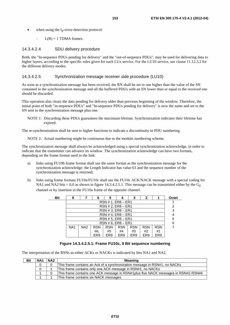
ETSI
ETSI EN 300 175-4 V2.4.1 (2012-04) 153
• when using the IP-error-detection protocol:
- L(R) = 1 TDMA frames.
14.3.4.2.4 SDU delivery procedure
Both, the "In-sequence PDUs pending for delivery" and the "out-of-sequence PDUs", may be used for delivering data to higher layers, according to the specific rules given for each LUx service. For the LU10 service, see clause 11.12.3.2 for the different delivery modes.
14.3.4.2.5 Synchronization message receiver side procedure (LU10)
As soon as a synchronization message has been received, the RN shall be set to one higher than the value of the SN contained in the synchronization message and all the buffered PDUs with an SN lower than or equal to the received one should be discarded.
This operation also clears the data pending for delivery older than previous beginning of the window. Therefore, the initial point of both "in-sequence PDUs" and "In-sequence PDUs pending for delivery" is now the same and set to the SN sent in the synchronization message plus one.
NOTE 1: Discarding these PDUs guarantees the maximum lifetime. Synchronization indicates their lifetime has expired.
The re-synchronization shall be sent to higher functions to indicate a discontinuity in PDU numbering.
NOTE 2: Actual numbering might be continuous due to the modulo numbering scheme.
The synchronization message shall always be acknowledged using a special synchronization acknowledge, in order to indicate that the transmitter can advance its window. The synchronization acknowledge can have two formats, depending on the frame format used in the link:
a) links using FU10b frame format shall use the same format as the synchronization message for the synchronization acknowledge: the Length Indicator has value 63 and the sequence number of the synchronization message is returned;
b) links using frame formats FU10a/FU10c shall use the FU10c ACK/NACK message with a special coding for NA1 and NA2 bits = 0,0 as shown in figure 14.3.4.2.5.1. This message can be transmitted either by the GF channel or by insertion in the FU10a frame of the opposite channel.
Bit 8 7 6 5 4 3 2 1 Octet RSN # 1, ER8 – ER1 1 RSN # 2, ER8 – ER1 2 RSN # 3, ER8 – ER1 3 RSN # 4, ER8 – ER1 4 RSN # 5, ER8 – ER1 5 RSN # 6, ER8 – ER1 6 NA1 NA2 RSN
#6, ER9
RSN #5
ER9
RSN #4
ER9
RSN #3
ER9
RSN #2
ER9
RSN #1
ER9
7
Figure 14.3.4.2.5.1: Frame FU10c, 9 Bit sequence numbering
The interpretation of the RSNs as either ACKs or NACKs is indicated by bits NA1 and NA2.
Bit NA1 NA2 Meaning 0 0 This frame contains an Ack of a synchronization message in RSN#1, no NACKs 0 1 This frame contains only one ACK message in RSN#1, no NACKs 1 0 This frame contains one ACK message in RSN#1plus five NACK messages in RSN#2-RSN#6 1 1 This frame contains six NACK messages
ETSI
ETSI EN 300 175-4 V2.4.1 (2012-04) 154
14.3.4.2.6 Reception of an abnormal SDU termination/abort signal (LU10)
In the event of receiving an abnormal SDU termination / abort signal, as defined in clause 14.3.4.1.3, the receiving entity shall discard the abnormally terminated SDU and shall not pass it to higher layers. In implementations when delivering of SDU to higher layers is allowed before SDU termination (i.e. PDU delivery mode), then an "abort" signal shall be passed and the receiving entity shall be in charge of handling the abnormal condition.
NOTE 1: In most cases, it means discarding the whole SDU. In some cases, for instance, when part of the SDU was released out of the DECT system, by a data link (i.e by a TCP connection), it means the transmission of an equivalent "abort" signal by such connection. If there is no way to do that, then the DECT system should not release externally parts of the SDU before the complete reception of it.
NOTE 2: In some special cases, for instance, when the transported payload is an application protocol, the destination application layer entity may handle the abnormal case in its own way.
14.3.5 Class 3 procedures
Class 3 operation uses both SNs and RNs. The RNs provide both window control to avoid possible sequencing errors, and also invoke automatic DLC retransmission. The DLC retransmission shall operate a selective retransmission protocol, combined with a lifetime limit on all packets to provide a guaranteed throughput.
14.3.5.1 Sending side procedure
The sending entity shall add SNs to all frames in the order specified by that entity. The I/R bit shall be set to "1" for the first transmission and to "0" for all retransmissions.
The resulting frames shall be submitted to the MAC layer in the order of ascending SN.
NOTE 1: This rule means that retransmissions always have priority relative to first transmissions.
The sending entity shall maintain a maximum window size between the SN and the last received RN. The maximum window size shall be equal to the (Modulus) of the SN used. A lower maximum value may be negotiated at call establishment (see clause 14.2.4). A smaller operating window size may be unilaterally adopted by the sending entity at any time.
Due to the modulus operation, each SN may be re-used several times during the life of the link. The minimum interval between re-use shall meet the following requirements:
1) a SN shall not exceed the maximum window size;
2) a SN shall not be re-used within L(S) TDMA frames of the most recent previous use of that number.
The value of L(S) shall be equal to 2.
The maximum lifetime of each frame shall be limited to T(R) TDMA frames. This lifetime limit should be defined at call establishment, and shall not be subsequently changed. When this limit is exceeded for a given frame, the frame shall not be retransmitted (or transmitted) and the data should be discarded. If the lifetime limit is not specified at call establishment the following value shall apply:
• T(R) default value shall be 15 TDMA frames.
NOTE 2: The value T(R) should normally be negotiated with the <<transit-delay>> element during call establishment (see EN 300 175-5 [5]).
The discarding of a frame shall not be treated as equivalent to acknowledgement of the SN. In all cases, the SN of that frame shall not be reused until the SN has been acknowledged by the peer. The peer entity maintains a corresponding lifetime limit, and should normally issue a (false) acknowledgement for expired frames when their lifetime limit is reached.
Whenever the window size limit is reached (thereby halting further transmissions) the sending side shall commence retransmission of all unexpired but outstanding frames, starting from the oldest unacknowledged frame. This automatic retransmission shall be stopped whenever a usable RN is received (i.e. an RN that acknowledges one or more outstanding frames), and normal transmission or retransmission procedures will be resumed.
ETSI
ETSI EN 300 175-4 V2.4.1 (2012-04) 155
Received RNs with the A/N bit set to "1" shall be treated as a positive acknowledgement for all frames up to an including the frame number RN - 1. This positive acknowledgement shall cause an immediate stop to any redundant (unnecessary) retransmissions that may have been scheduled as a result of previously received negative acknowledgements.
Received RNs with the A/N bit set to "0" shall be treated as a negative acknowledgement for the single frame number RN. Receipt of a NACK shall cause a selective retransmission of the indicated frame(s).
14.3.5.2 Receiving side procedure
The receiving entity shall accept data packets from the MAC layer in any order. Packets marked as type "unknown" and any packets that are indicated to contain errors in the first portion (MAC subfield BO) shall be discarded. The remaining packets are assumed to contain valid frames, and shall be processed in their order of arrival.
In-sequence frames are defined as a series of one or more frames that contain no errors and that contain SN(s) that together form a continuous series of SNs when considered together with other received but undelivered frames. All in-sequence frames shall be immediately delivered to the higher functions.
NOTE 1: Most higher function users of class 3 retransmission are expected to provide frame buffering such that a continuous flow of data is produced. The buffer size should be greater than the product of connection bandwidth and maximum frame lifetime.
Out-of-sequence frames are defined as all other frames (i.e. a sequence of one or more frames that do not form a continuous series of SNs or contain some errors). These frames may only be delivered after they have been buffered for T(R) TDMA frames after their arrival. During this buffering period, out-of-sequence frames may become in-sequence frames due to the arrival of one or more missing frames. In this event, the frames shall be immediately delivered to the higher layer.
As soon as an out-of-sequence frame is detected the receiving entity shall return an immediate negative acknowledgement, by returning at least one frame containing the missing RNs and the A/N bit set to "0". If necessary, multiple RN values shall be returned; one for each missing frame.
NOTE 2: Out of sequence frames may be discarded before this time limit, in order to limit buffer sizes.
The value of T(R) shall be equal to the maximum frame lifetime. This lifetime limit should be defined at call establishment, and shall not be subsequently changed. If the lifetime limit is not specified at call establishment the following value shall apply:
• T(R) default value shall be 15 TDMA frames.
NOTE 3: The value T(R) should normally be negotiated with the <<transit-delay>> element during call establishment (see EN 300 175-5 [5]).
During the total buffering period T(R) a frame may arrive that is a duplicate of one of the buffered frames. If the original buffered frame was correct, any such duplicates shall be discarded. If the original buffered frame contained errors, the duplicate may be used to correct those errors, using selective replacement of erroneous portions (replacement of MAC BN subfields).
NOTE 4: Selective replacement is only performed for frames with the same SN. This requires error free reception of the B0 subfield (i.e. the subfield containing the SN).
If after buffering for T(R) TDMA frames, out-of-sequence frames remain out-of-sequence, all of the valid frames shall nonetheless be delivered to higher functions, together with an indication for all missing frames. The receiving entity shall then act as though the frames had been received in sequence. In particular, the RN shall be updated to acknowledge acceptance of these frames.
Whenever frames are delivered to the higher functions, the RN for all positive acknowledgements shall be set equal to the highest delivered SN + 1.
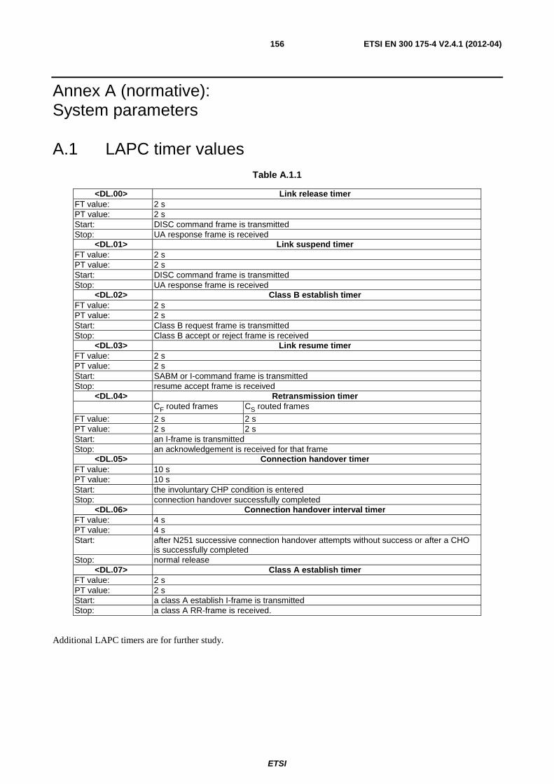
ETSI
ETSI EN 300 175-4 V2.4.1 (2012-04) 156
Annex A (normative): System parameters
A.1 LAPC timer values Table A.1.1
<DL.00> Link release timer FT value: 2 s PT value: 2 s Start: DISC command frame is transmitted Stop: UA response frame is received
<DL.01> Link suspend timer FT value: 2 s PT value: 2 s Start: DISC command frame is transmitted Stop: UA response frame is received
<DL.02> Class B establish timer FT value: 2 s PT value: 2 s Start: Class B request frame is transmitted Stop: Class B accept or reject frame is received
<DL.03> Link resume timer FT value: 2 s PT value: 2 s Start: SABM or I-command frame is transmitted Stop: resume accept frame is received
<DL.04> Retransmission timer CF routed frames CS routed frames
FT value: 2 s 2 s PT value: 2 s 2 s Start: an I-frame is transmitted Stop: an acknowledgement is received for that frame
<DL.05> Connection handover timer FT value: 10 s PT value: 10 s Start: the involuntary CHP condition is entered Stop: connection handover successfully completed
<DL.06> Connection handover interval timer FT value: 4 s PT value: 4 s Start: after N251 successive connection handover attempts without success or after a CHO
is successfully completed Stop: normal release
<DL.07> Class A establish timer FT value: 2 s PT value: 2 s Start: a class A establish I-frame is transmitted Stop: a class A RR-frame is received.
Additional LAPC timers are for further study.
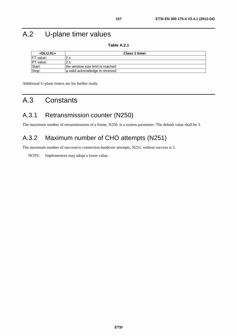
ETSI
ETSI EN 300 175-4 V2.4.1 (2012-04) 157
A.2 U-plane timer values Table A.2.1
<DLU.01> Class 1 timer FT value: 2 s PT value: 2 s Start: the window size limit is reached Stop: a valid acknowledge is received
Additional U-plane timers are for further study.
A.3 Constants
A.3.1 Retransmission counter (N250) The maximum number of retransmissions of a frame, N250, is a system parameter. The default value shall be 3.
A.3.2 Maximum number of CHO attempts (N251) The maximum number of successive connection handover attempts, N251, without success is 3.
NOTE: Implementors may adopt a lower value.
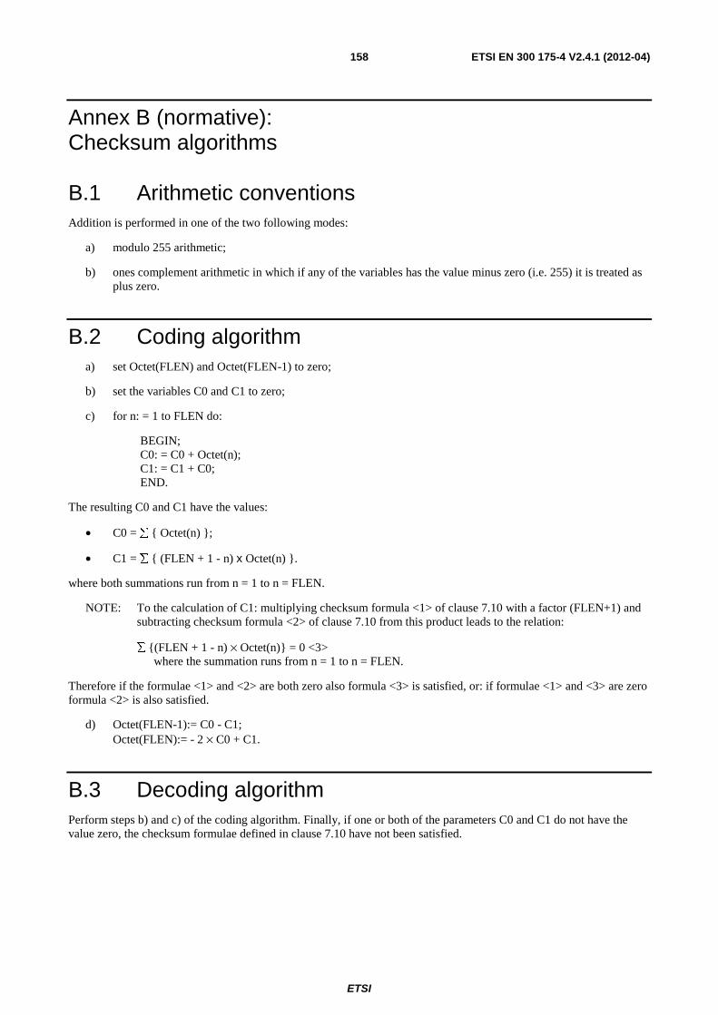
ETSI
ETSI EN 300 175-4 V2.4.1 (2012-04) 158
Annex B (normative): Checksum algorithms
B.1 Arithmetic conventions Addition is performed in one of the two following modes:
a) modulo 255 arithmetic;
b) ones complement arithmetic in which if any of the variables has the value minus zero (i.e. 255) it is treated as plus zero.
B.2 Coding algorithm a) set Octet(FLEN) and Octet(FLEN-1) to zero;
b) set the variables C0 and C1 to zero;
c) for n: = 1 to FLEN do:
BEGIN; C0: = C0 + Octet(n); C1: = C1 + C0; END.
The resulting C0 and C1 have the values:
• C0 = ∑ { Octet(n) };
• C1 = ∑ { (FLEN + 1 - n) x Octet(n) }.
where both summations run from n = 1 to n = FLEN.
NOTE: To the calculation of C1: multiplying checksum formula <1> of clause 7.10 with a factor (FLEN+1) and subtracting checksum formula <2> of clause 7.10 from this product leads to the relation:
∑ {(FLEN + 1 - n) × Octet(n)} = 0 <3> where the summation runs from n = 1 to n = FLEN.
Therefore if the formulae <1> and <2> are both zero also formula <3> is satisfied, or: if formulae <1> and <3> are zero formula <2> is also satisfied.
d) Octet(FLEN-1):= C0 - C1; Octet(FLEN):= - 2 × C0 + C1.
B.3 Decoding algorithm Perform steps b) and c) of the coding algorithm. Finally, if one or both of the parameters C0 and C1 do not have the value zero, the checksum formulae defined in clause 7.10 have not been satisfied.

ETSI
ETSI EN 300 175-4 V2.4.1 (2012-04) 159
B.4 Some examples To verify correct implementation of the checksum calculation, two examples are given (hexadecimal notation):
EXAMPLE 1: Two octets of data: FE02 Calculated checksum FE00.
EXAMPLE 2: Three octets of data: 910001 Calculated checksum B7B5.
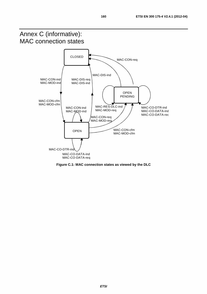
ETSI
ETSI EN 300 175-4 V2.4.1 (2012-04) 160
Annex C (informative): MAC connection states
CLOSED
OPEN
MAC-CON-req
MAC-DIS-ind
MAC-CO-DTR-ind
MAC-CON-indMAC-MOD-ind
MAC-CON-cfmMAC-MOD-cfm
MAC-DIS-reqMAC-DIS-ind
MAC-CON-indMAC-MOD-ind
MAC-CO-DATA-indMAC-CO-DATA-req
MAC-CON-cfmMAC-MOD-cfm
MAC-CON-reqMAC-MOD-req
MAC-RES-DLC-indMAC-MOD-req
MAC-CO-DTR-indMAC-CO-DATA-indMAC-CO-DATA-req
OPENPENDING
Figure C.1: MAC connection states as viewed by the DLC
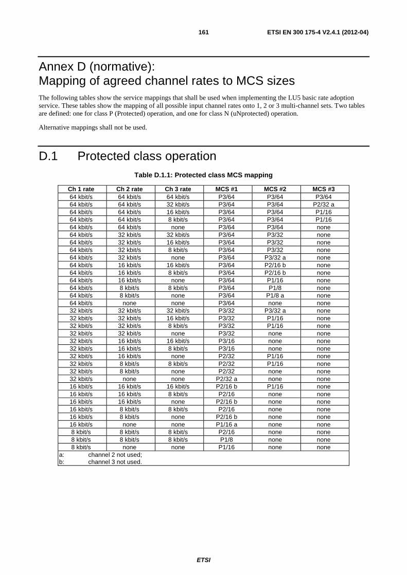
ETSI
ETSI EN 300 175-4 V2.4.1 (2012-04) 161
Annex D (normative): Mapping of agreed channel rates to MCS sizes The following tables show the service mappings that shall be used when implementing the LU5 basic rate adoption service. These tables show the mapping of all possible input channel rates onto 1, 2 or 3 multi-channel sets. Two tables are defined: one for class P (Protected) operation, and one for class N (uNprotected) operation.
Alternative mappings shall not be used.
D.1 Protected class operation Table D.1.1: Protected class MCS mapping
Ch 1 rate Ch 2 rate Ch 3 rate MCS #1 MCS #2 MCS #3 64 kbit/s 64 kbit/s 64 kbit/s P3/64 P3/64 P3/64 64 kbit/s 64 kbit/s 32 kbit/s P3/64 P3/64 P2/32 a 64 kbit/s 64 kbit/s 16 kbit/s P3/64 P3/64 P1/16 64 kbit/s 64 kbit/s 8 kbit/s P3/64 P3/64 P1/16 64 kbit/s 64 kbit/s none P3/64 P3/64 none 64 kbit/s 32 kbit/s 32 kbit/s P3/64 P3/32 none 64 kbit/s 32 kbit/s 16 kbit/s P3/64 P3/32 none 64 kbit/s 32 kbit/s 8 kbit/s P3/64 P3/32 none 64 kbit/s 32 kbit/s none P3/64 P3/32 a none 64 kbit/s 16 kbit/s 16 kbit/s P3/64 P2/16 b none 64 kbit/s 16 kbit/s 8 kbit/s P3/64 P2/16 b none 64 kbit/s 16 kbit/s none P3/64 P1/16 none 64 kbit/s 8 kbit/s 8 kbit/s P3/64 P1/8 none 64 kbit/s 8 kbit/s none P3/64 P1/8 a none 64 kbit/s none none P3/64 none none 32 kbit/s 32 kbit/s 32 kbit/s P3/32 P3/32 a none 32 kbit/s 32 kbit/s 16 kbit/s P3/32 P1/16 none 32 kbit/s 32 kbit/s 8 kbit/s P3/32 P1/16 none 32 kbit/s 32 kbit/s none P3/32 none none 32 kbit/s 16 kbit/s 16 kbit/s P3/16 none none 32 kbit/s 16 kbit/s 8 kbit/s P3/16 none none 32 kbit/s 16 kbit/s none P2/32 P1/16 none 32 kbit/s 8 kbit/s 8 kbit/s P2/32 P1/16 none 32 kbit/s 8 kbit/s none P2/32 none none 32 kbit/s none none P2/32 a none none 16 kbit/s 16 kbit/s 16 kbit/s P2/16 b P1/16 none 16 kbit/s 16 kbit/s 8 kbit/s P2/16 none none 16 kbit/s 16 kbit/s none P2/16 b none none 16 kbit/s 8 kbit/s 8 kbit/s P2/16 none none 16 kbit/s 8 kbit/s none P2/16 b none none 16 kbit/s none none P1/16 a none none 8 kbit/s 8 kbit/s 8 kbit/s P2/16 none none 8 kbit/s 8 kbit/s 8 kbit/s P1/8 none none 8 kbit/s none none P1/16 none none
a: channel 2 not used; b: channel 3 not used.
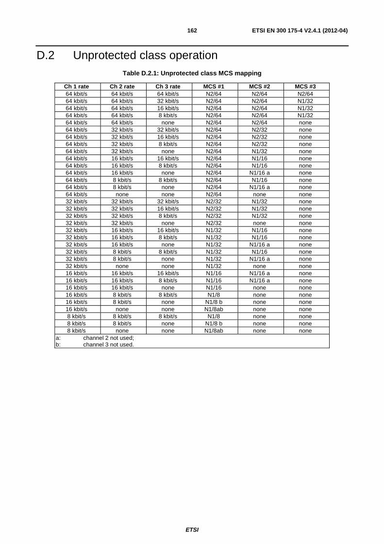
ETSI
ETSI EN 300 175-4 V2.4.1 (2012-04) 162
D.2 Unprotected class operation Table D.2.1: Unprotected class MCS mapping
Ch 1 rate Ch 2 rate Ch 3 rate MCS #1 MCS #2 MCS #3 64 kbit/s 64 kbit/s 64 kbit/s N2/64 N2/64 N2/64 64 kbit/s 64 kbit/s 32 kbit/s N2/64 N2/64 N1/32 64 kbit/s 64 kbit/s 16 kbit/s N2/64 N2/64 N1/32 64 kbit/s 64 kbit/s 8 kbit/s N2/64 N2/64 N1/32 64 kbit/s 64 kbit/s none N2/64 N2/64 none 64 kbit/s 32 kbit/s 32 kbit/s N2/64 N2/32 none 64 kbit/s 32 kbit/s 16 kbit/s N2/64 N2/32 none 64 kbit/s 32 kbit/s 8 kbit/s N2/64 N2/32 none 64 kbit/s 32 kbit/s none N2/64 N1/32 none 64 kbit/s 16 kbit/s 16 kbit/s N2/64 N1/16 none 64 kbit/s 16 kbit/s 8 kbit/s N2/64 N1/16 none 64 kbit/s 16 kbit/s none N2/64 N1/16 a none 64 kbit/s 8 kbit/s 8 kbit/s N2/64 N1/16 none 64 kbit/s 8 kbit/s none N2/64 N1/16 a none 64 kbit/s none none N2/64 none none 32 kbit/s 32 kbit/s 32 kbit/s N2/32 N1/32 none 32 kbit/s 32 kbit/s 16 kbit/s N2/32 N1/32 none 32 kbit/s 32 kbit/s 8 kbit/s N2/32 N1/32 none 32 kbit/s 32 kbit/s none N2/32 none none 32 kbit/s 16 kbit/s 16 kbit/s N1/32 N1/16 none 32 kbit/s 16 kbit/s 8 kbit/s N1/32 N1/16 none 32 kbit/s 16 kbit/s none N1/32 N1/16 a none 32 kbit/s 8 kbit/s 8 kbit/s N1/32 N1/16 none 32 kbit/s 8 kbit/s none N1/32 N1/16 a none 32 kbit/s none none N1/32 none none 16 kbit/s 16 kbit/s 16 kbit/s N1/16 N1/16 a none 16 kbit/s 16 kbit/s 8 kbit/s N1/16 N1/16 a none 16 kbit/s 16 kbit/s none N1/16 none none 16 kbit/s 8 kbit/s 8 kbit/s N1/8 none none 16 kbit/s 8 kbit/s none N1/8 b none none 16 kbit/s none none N1/8ab none none 8 kbit/s 8 kbit/s 8 kbit/s N1/8 none none 8 kbit/s 8 kbit/s none N1/8 b none none 8 kbit/s none none N1/8ab none none
a: channel 2 not used; b: channel 3 not used.
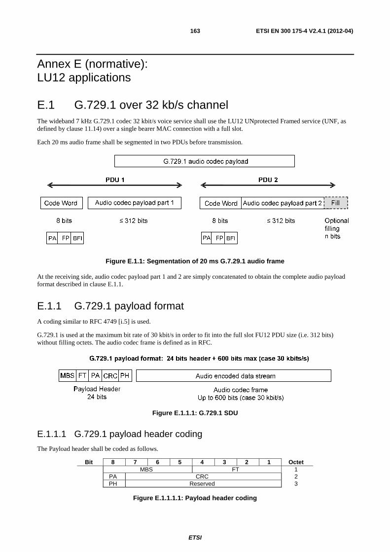
ETSI
ETSI EN 300 175-4 V2.4.1 (2012-04) 163
Annex E (normative): LU12 applications
E.1 G.729.1 over 32 kb/s channel The wideband 7 kHz G.729.1 codec 32 kbit/s voice service shall use the LU12 UNprotected Framed service (UNF, as defined by clause 11.14) over a single bearer MAC connection with a full slot.
Each 20 ms audio frame shall be segmented in two PDUs before transmission.
Figure E.1.1: Segmentation of 20 ms G.7.29.1 audio frame
At the receiving side, audio codec payload part 1 and 2 are simply concatenated to obtain the complete audio payload format described in clause E.1.1.
E.1.1 G.729.1 payload format A coding similar to RFC 4749 [i.5] is used.
G.729.1 is used at the maximum bit rate of 30 kbit/s in order to fit into the full slot FU12 PDU size (i.e. 312 bits) without filling octets. The audio codec frame is defined as in RFC.
Figure E.1.1.1: G.729.1 SDU
E.1.1.1 G.729.1 payload header coding
The Payload header shall be coded as follows.
Bit 8 7 6 5 4 3 2 1 Octet MBS FT 1 PA CRC 2 PH Reserved 3
Figure E.1.1.1.1: Payload header coding
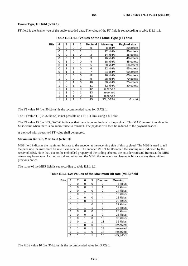
ETSI
ETSI EN 300 175-4 V2.4.1 (2012-04) 164
Frame Type, FT field (octet 1):
FT field is the Frame type of the audio encoded data. The value of the FT field is set according to table E.1.1.1.1.
Table E.1.1.1.1: Values of the Frame Type (FT) field
Bits 4 3 2 1 Decimal Meaning Payload size 0 0 0 0 0 8 kbit/s 20 octets 0 0 0 1 1 12 kbit/s 30 octets 0 0 1 0 2 14 kbit/s 35 octets 0 0 1 1 3 16 kbit/s 40 octets 0 1 0 0 4 18 kbit/s 45 octets 0 1 0 1 5 20 kbit/s 50 octets 0 1 1 0 6 22 kbit/s 55 octets 0 1 1 1 7 24 kbit/s 60 octets 1 0 0 0 8 26 kbit/s 65 octets 1 0 0 1 9 28 kbit/s 70 octets 1 0 1 0 10 30 kbit/s 75 octets 1 0 1 1 11 32 kbit/s 80 octets 1 1 0 0 12 reserved 1 1 0 1 13 reserved 1 1 1 0 14 reserved 1 1 1 1 15 NO_DATA 0 octet
The FT value 10 (i.e. 30 kbit/s) is the recommended value for G.729.1.
The FT value 11 (i.e. 32 kbit/s) is not possible on a DECT link using a full slot.
The FT value 15 (i.e. NO_DATA) indicates that there is no audio data in the payload. This MAY be used to update the MBS value when there is no audio frame to transmit. The payload will then be reduced to the payload header.
A payload with a reserved FT value shall be ignored.
Maximum Bit rate, MBS field (octet 1):
MBS field indicates the maximum bit rate to the encoder at the receiving side of this payload. The MBS is used to tell the peer side the maximum bit rate it can receive. The encoder MUST NOT exceed the sending rate indicated by the received MBS. Note that, due to the embedded property of the coding scheme, the encoder can send frames at the MBS rate or any lower rate. As long as it does not exceed the MBS, the encoder can change its bit rate at any time without previous notice.
The value of the MBS field is set according to table E.1.1.1.2.
Table E.1.1.1.2: Values of the Maximum Bit rate (MBS) field
Bits 8 7 6 5 Decimal Meaning 0 0 0 0 0 8 kbit/s 0 0 0 1 1 12 kbit/s 0 0 1 0 2 14 kbit/s 0 0 1 1 3 16 kbit/s 0 1 0 0 4 18 kbit/s 0 1 0 1 5 20 kbit/s 0 1 1 0 6 22 kbit/s 0 1 1 1 7 24 kbit/s 1 0 0 0 8 26 kbit/s 1 0 0 1 9 28 kbit/s 1 0 1 0 10 30 kbit/s 1 0 1 1 11 32 kbit/s 1 1 0 0 12 reserved 1 1 0 1 13 reserved 1 1 1 0 14 reserved 1 1 1 1 15 NO_MBS
The MBS value 10 (i.e. 30 kbit/s) is the recommended value for G.729.1.
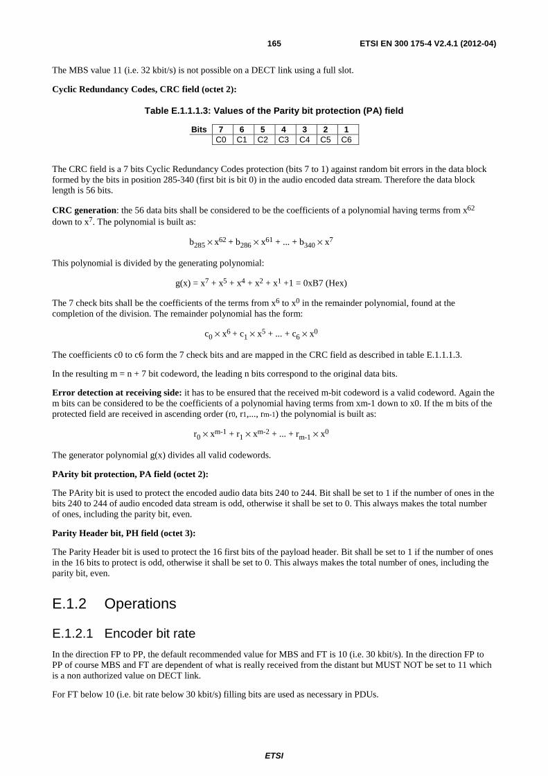
ETSI
ETSI EN 300 175-4 V2.4.1 (2012-04) 165
The MBS value 11 (i.e. 32 kbit/s) is not possible on a DECT link using a full slot.
Cyclic Redundancy Codes, CRC field (octet 2):
Table E.1.1.1.3: Values of the Parity bit protection (PA) field
Bits 7 6 5 4 3 2 1 C0 C1 C2 C3 C4 C5 C6
The CRC field is a 7 bits Cyclic Redundancy Codes protection (bits 7 to 1) against random bit errors in the data block formed by the bits in position 285-340 (first bit is bit 0) in the audio encoded data stream. Therefore the data block length is 56 bits.
CRC generation: the 56 data bits shall be considered to be the coefficients of a polynomial having terms from x62 down to x7. The polynomial is built as:
b285 × x62 + b286 × x61 + ... + b340 × x7
This polynomial is divided by the generating polynomial:
g(x) = x7 + x5 + x4 + x2 + x1 +1 = 0xB7 (Hex)
The 7 check bits shall be the coefficients of the terms from x6 to x0 in the remainder polynomial, found at the completion of the division. The remainder polynomial has the form:
c0 × x6 + c1 × x5 + ... + c6 × x0
The coefficients c0 to c6 form the 7 check bits and are mapped in the CRC field as described in table E.1.1.1.3.
In the resulting m = n + 7 bit codeword, the leading n bits correspond to the original data bits.
Error detection at receiving side: it has to be ensured that the received m-bit codeword is a valid codeword. Again the m bits can be considered to be the coefficients of a polynomial having terms from xm-1 down to x0. If the m bits of the protected field are received in ascending order (r0, r1,..., rm-1) the polynomial is built as:
r0 × xm-1 + r1 × xm-2 + ... + rm-1 × x0
The generator polynomial g(x) divides all valid codewords.
PArity bit protection, PA field (octet 2):
The PArity bit is used to protect the encoded audio data bits 240 to 244. Bit shall be set to 1 if the number of ones in the bits 240 to 244 of audio encoded data stream is odd, otherwise it shall be set to 0. This always makes the total number of ones, including the parity bit, even.
Parity Header bit, PH field (octet 3):
The Parity Header bit is used to protect the 16 first bits of the payload header. Bit shall be set to 1 if the number of ones in the 16 bits to protect is odd, otherwise it shall be set to 0. This always makes the total number of ones, including the parity bit, even.
E.1.2 Operations
E.1.2.1 Encoder bit rate
In the direction FP to PP, the default recommended value for MBS and FT is 10 (i.e. 30 kbit/s). In the direction FP to PP of course MBS and FT are dependent of what is really received from the distant but MUST NOT be set to 11 which is a non authorized value on DECT link.
For FT below 10 (i.e. bit rate below 30 kbit/s) filling bits are used as necessary in PDUs.
ETSI
ETSI EN 300 175-4 V2.4.1 (2012-04) 166
24 kbit/s use case: a FT of 7 corresponds to a complete G.729.1 payload format frame of 24 (header) + 480 (audio frame) = 504 bits. PDU1 is then composed of a code word of value "00" Hex followed by the first 312 bits of G.729.1 payload format. PDU2 is composed of a code word of value "82" Hex followed by last 192 bits G.729.1 payload format, followed by 120 fill bits.
12 kbit/s use case: a FT of 1 corresponds to a complete G.729.1 payload format frame of 24 (header) + 240 (audio frame) = 264 bits. PDU1 is then composed of a code word of value "00" Hex followed by the full 264 bits of G.729.1 payload format, followed by 48 fill bits. PDU2 is composed of a code word of value "82" Hex followed by 312 fill bits.
In case of a bad indication frame (indicated with BFI = 1 in Code Word field), the G.729.1 payload format should be adapted with a FT of 15 (NO_DATA), a MBS of 15 (NO MBS) and a complete PDU of fill bits.
E.1.2.2 Protection against random errors
A one byte redundancy information is included in the payload header. It is composed of two parts:
• A 7 bit CRC is used to verify 56 bits in positions 285-340 in the audio codec frame (first position is the position 0). The used generator polynomial is "B7" Hex. This polynomial can detect 100 % 1, 2, 3, 5, 7, … bit errors and more than 98 % of 4 and 6 bit errors. This CRC shall be calculated on a 600 bits audio frame. For bit rate below 30 kbit/s, audio payload frame shall be padded with "0" bits before CRC calculation.
• One parity bit used to verify 5 bits in positions 240-244 in the audio codec frame.
The redundancy information covers the only sensitive part of the G.729.1 bitstream to bit errors. It offers very strong benefit in terms of MOS score in case of random bit errors in the concerned bits. Other parts of the bitstream are very robust to random bit errors.
This dedicated CRC must be inserted from FP to PP and from PP to FP directions and should replace the use of the original X-CRC as it is not codec optimized. Insertion on the FP side may be done upper in the network.

ETSI
ETSI EN 300 175-4 V2.4.1 (2012-04) 167
Annex F (informative): Bibliography ETSI EN 300 176 (all parts): "Digital Enhanced Cordless Telecommunications (DECT); Test specification".
ETSI EN 300 175-7: "Digital Enhanced Cordless Telecommunications (DECT); Common Interface (CI); Part 7: Security features".
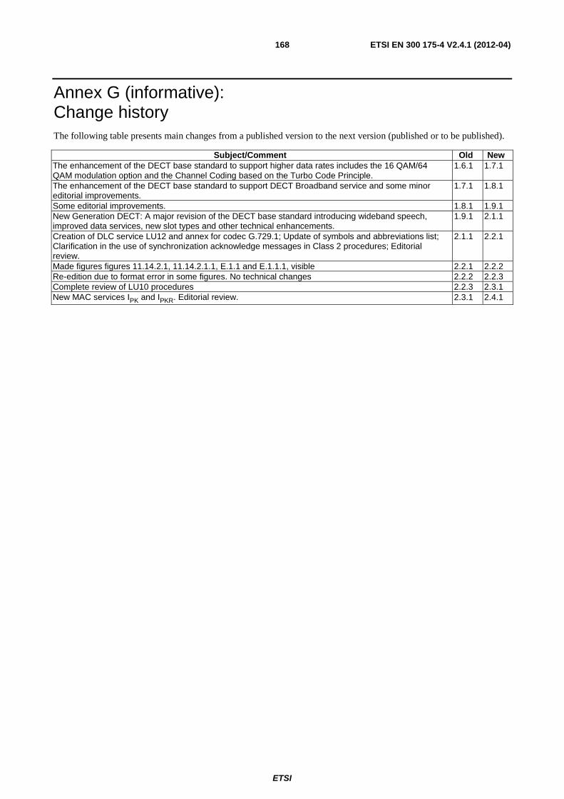
ETSI
ETSI EN 300 175-4 V2.4.1 (2012-04) 168
Annex G (informative): Change history The following table presents main changes from a published version to the next version (published or to be published).
Subject/Comment Old New The enhancement of the DECT base standard to support higher data rates includes the 16 QAM/64 QAM modulation option and the Channel Coding based on the Turbo Code Principle.
1.6.1 1.7.1
The enhancement of the DECT base standard to support DECT Broadband service and some minor editorial improvements.
1.7.1 1.8.1
Some editorial improvements. 1.8.1 1.9.1 New Generation DECT: A major revision of the DECT base standard introducing wideband speech, improved data services, new slot types and other technical enhancements.
1.9.1 2.1.1
Creation of DLC service LU12 and annex for codec G.729.1; Update of symbols and abbreviations list; Clarification in the use of synchronization acknowledge messages in Class 2 procedures; Editorial review.
2.1.1 2.2.1
Made figures figures 11.14.2.1, 11.14.2.1.1, E.1.1 and E.1.1.1, visible 2.2.1 2.2.2 Re-edition due to format error in some figures. No technical changes 2.2.2 2.2.3 Complete review of LU10 procedures 2.2.3 2.3.1 New MAC services IPK and IPKR. Editorial review. 2.3.1 2.4.1
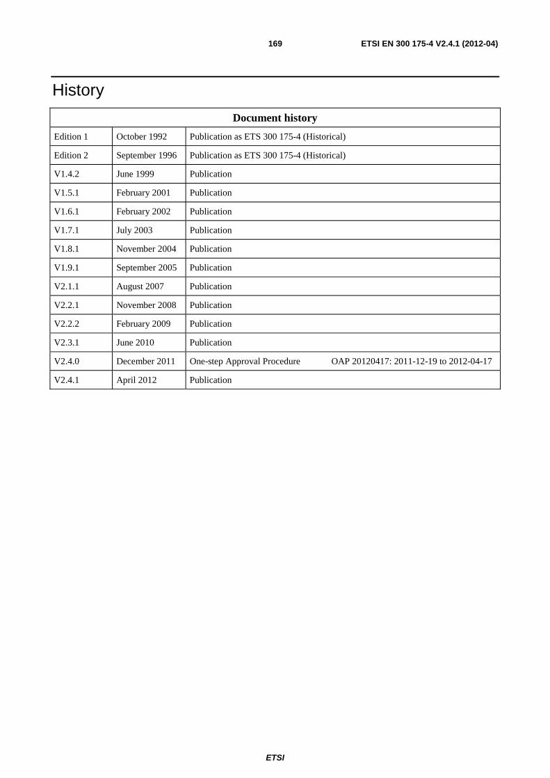
ETSI
ETSI EN 300 175-4 V2.4.1 (2012-04) 169
History
Document history
Edition 1 October 1992 Publication as ETS 300 175-4 (Historical)
Edition 2 September 1996 Publication as ETS 300 175-4 (Historical)
V1.4.2 June 1999 Publication
V1.5.1 February 2001 Publication
V1.6.1 February 2002 Publication
V1.7.1 July 2003 Publication
V1.8.1 November 2004 Publication
V1.9.1 September 2005 Publication
V2.1.1 August 2007 Publication
V2.2.1 November 2008 Publication
V2.2.2 February 2009 Publication
V2.3.1 June 2010 Publication
V2.4.0 December 2011 One-step Approval Procedure OAP 20120417: 2011-12-19 to 2012-04-17
V2.4.1 April 2012 Publication


