ETSI EN 301 526 V1.1.1 (2006-07) Harmonized European Standard (Telecommunications series) Electromagnetic compatibility and Radio spectrum Matters (ERM); Harmonized EN for CDMA spread spectrum mobile stations operating in the 450 MHz cellular band (CDMA 450) and 410, 450 and 870 MHz PAMR bands (CDMA-PAMR) covering essential requirements of article 3.2 of the R&TTE Directive
Transcript
ETSI EN 301 526 V1.1.1 (2006-07)
Harmonized European Standard (Telecommunications series)
Electromagnetic compatibilityand Radio spectrum Matters (ERM);
Harmonized EN for CDMA spread spectrum mobile stationsoperating in the 450 MHz cellular band (CDMA 450)
and 410, 450 and 870 MHz PAMR bands (CDMA-PAMR)covering essential requirements
650 Route des Lucioles F-06921 Sophia Antipolis Cedex - FRANCE
Tel.: +33 4 92 94 42 00 Fax: +33 4 93 65 47 16
Siret N° 348 623 562 00017 - NAF 742 C
Association à but non lucratif enregistrée à la Sous-Préfecture de Grasse (06) N° 7803/88
Important notice
Individual copies of the present document can be downloaded from: http://www.etsi.org
The present document may be made available in more than one electronic version or in print. In any case of existing or perceived difference in contents between such versions, the reference version is the Portable Document Format (PDF).
In case of dispute, the reference shall be the printing on ETSI printers of the PDF version kept on a specific network drive within ETSI Secretariat.
Users of the present document should be aware that the document may be subject to revision or change of status. Information on the current status of this and other ETSI documents is available at
http://portal.etsi.org/tb/status/status.asp
If you find errors in the present document, please send your comment to one of the following services: http://portal.etsi.org/chaircor/ETSI_support.asp
Copyright Notification
No part may be reproduced except as authorized by written permission. The copyright and the foregoing restriction extend to reproduction in all media.
DECTTM, PLUGTESTSTM and UMTSTM are Trade Marks of ETSI registered for the benefit of its Members. TIPHONTM and the TIPHON logo are Trade Marks currently being registered by ETSI for the benefit of its Members. 3GPPTM is a Trade Mark of ETSI registered for the benefit of its Members and of the 3GPP Organizational Partners.
Intellectual Property Rights ................................................................................................................................6
4 Technical requirements specifications ...................................................................................................16 4.1 Environmental profile.......................................................................................................................................16 4.2 Conformance requirements ..............................................................................................................................17 4.2.1 Introduction.................................................................................................................................................17 4.2.2 Transmitter conducted unwanted emissions ...............................................................................................17 4.2.2.1 Definition ..............................................................................................................................................17 4.2.2.2 Limits ....................................................................................................................................................17 4.2.2.2.1 Limits for band class 5 mobile stations ...........................................................................................17 4.2.2.2.2 Limits for band classes 11 and 12 mobile stations ..........................................................................18 4.2.2.3 Conformance.........................................................................................................................................18 4.2.3 Maximum RF output power........................................................................................................................18 4.2.3.1 Definition ..............................................................................................................................................18 4.2.3.2 Limits ....................................................................................................................................................18 4.2.3.2.1 Limits for Band Classes 5 and 11 mobile stations...........................................................................19 4.2.3.2.2 Limits for Band Class 12 mobile stations........................................................................................19 4.2.3.3 Conformance.........................................................................................................................................19 4.2.4 Radiated spurious unwanted emissions.......................................................................................................19 4.2.4.1 Definition ..............................................................................................................................................19 4.2.4.2 Limits ....................................................................................................................................................19 4.2.4.3 Conformance.........................................................................................................................................20 4.2.5 Minimum controlled output power .............................................................................................................20 4.2.5.1 Definition ..............................................................................................................................................20 4.2.5.2 Limits ....................................................................................................................................................20 4.2.5.3 Conformance.........................................................................................................................................20 4.2.6 Control and monitoring function ................................................................................................................20 4.2.6.1 Definition ..............................................................................................................................................20 4.2.6.2 Limits ....................................................................................................................................................20 4.2.6.3 Conformance.........................................................................................................................................20 4.2.7 Supervision of Paging Channel or Forward Common Control Channel.....................................................21 4.2.7.1 Definition ..............................................................................................................................................21 4.2.7.2 Limits ....................................................................................................................................................21 4.2.7.3 Conformance.........................................................................................................................................21 4.2.8 Supervision of Forward Traffic Channel ....................................................................................................21 4.2.8.1 Definition ..............................................................................................................................................21 4.2.8.2 Limits ....................................................................................................................................................21 4.2.8.3 Conformance.........................................................................................................................................22 4.2.9 Supervision of Control Channel..................................................................................................................22 4.2.9.1 Definition ..............................................................................................................................................22 4.2.9.2 Limits ....................................................................................................................................................22 4.2.9.3 Conformance.........................................................................................................................................22 4.2.10 Supervision procedures in Variable Rate State ...........................................................................................23 4.2.10.1 Definition ..............................................................................................................................................23 4.2.10.2 Limits ....................................................................................................................................................23 4.2.10.3 Conformance.........................................................................................................................................23
ETSI
ETSI EN 301 526 V1.1.1 (2006-07) 4
4.2.11 Receiver single tone desensitization ...........................................................................................................23 4.2.11.1 Definition ..............................................................................................................................................23 4.2.11.2 Limits ....................................................................................................................................................24 4.2.11.2.1 Mobile station operating in 1x systems ...........................................................................................24 4.2.11.2.2 Mobile station operating in HRPD systems.....................................................................................24 4.2.11.3 Conformance.........................................................................................................................................24 4.2.12 Intermodulation spurious response attenuation...........................................................................................24 4.2.12.1 Definition ..............................................................................................................................................24 4.2.12.2 Limits ....................................................................................................................................................24 4.2.12.2.1 Mobile station operating in 1x systems ...........................................................................................24 4.2.12.2.2 Mobile station operating in HRPD systems.....................................................................................24 4.2.12.3 Conformance.........................................................................................................................................24 4.2.13 Conducted spurious emissions when not transmitting ................................................................................24 4.2.13.1 Definition ..............................................................................................................................................24 4.2.13.2 Limits ....................................................................................................................................................25 4.2.13.3 Conformance.........................................................................................................................................25
5 Testing for compliance with technical requirements..............................................................................25 5.1 Conditions for testing .......................................................................................................................................25 5.1.1 Introduction.................................................................................................................................................25 5.1.2 Standard equipment under test....................................................................................................................25 5.1.2.1 Basic equipment ....................................................................................................................................25 5.1.2.2 Ancillary equipment..............................................................................................................................25 5.2 Interpretation of the measurement results ........................................................................................................26 5.3 Essential radio test suites..................................................................................................................................27 5.3.1 Conducted unwanted emissions when transmitting ....................................................................................27 5.3.1.1 Test procedure for mobile stations supporting operation in 1x systems................................................27 5.3.1.2 Test procedure for mobile stations supporting operation in HRPD systems.........................................27 5.3.2 Maximum RF output power........................................................................................................................27 5.3.2.1 Test procedure for mobile stations supporting operation in 1x systems................................................27 5.3.2.2 Test procedure for mobile stations supporting operation in HRPD systems.........................................28 5.3.3 Radiated unwanted emissions .....................................................................................................................28 5.3.3.1 Test method...........................................................................................................................................28 5.3.3.2 Test configurations................................................................................................................................29 5.3.4 Minimum controlled output power .............................................................................................................29 5.3.4.1 Test procedure for mobile stations supporting operation in 1x systems................................................29 5.3.4.2 Test procedure for mobile stations supporting operation in HRPD systems.........................................29 5.3.5 Control and monitoring functions ...............................................................................................................30 5.3.5.1 Test method...........................................................................................................................................30 5.3.6 Supervision of Paging Channel or Forward Common Control Channel.....................................................30 5.3.7 Supervision of Forward Traffic Channel ....................................................................................................30 5.3.8 Supervision of Control Channel..................................................................................................................30 5.3.9 Supervision procedures in variable rate state..............................................................................................31 5.3.10 Single tone desensitization..........................................................................................................................31 5.3.10.1 Test procedure for mobile stations supporting operation in 1x systems................................................31 5.3.10.2 Test procedure for mobile stations supporting operation in HRPD systems.........................................31 5.3.11 Intermodulation spurious response attenuation...........................................................................................31 5.3.11.1 Test procedure for mobile stations supporting operation in 1x systems................................................31 5.3.11.2 Test procedure for mobile stations supporting operation in HRPD systems.........................................31 5.3.12 Conducted spurious emissions when not transmitting ................................................................................32 5.3.12.1 Test procedure for mobile stations supporting operation in 1x systems................................................32 5.3.12.2 Test procedure for mobile stations supporting operation in HRPD systems.........................................32
Annex A (normative): The HS Requirements and conformance Test specifications Table (HS-RTT)........................................................................................................33
Annex B (normative): Mobile station configurations .......................................................................36
Annex C (informative): Environmental profile specification .............................................................37
C.1 Test conditions, power supply and ambient temperatures......................................................................37
ETSI
ETSI EN 301 526 V1.1.1 (2006-07) 5
C.1.1 Normal and extreme test conditions .................................................................................................................37 C.1.2 Power sources...................................................................................................................................................37 C.1.2.1 Power sources for stand-alone equipment ..................................................................................................37 C.1.3 Normal test conditions......................................................................................................................................37 C.1.3.1 Normal temperature and humidity ..............................................................................................................37 C.1.3.2 Normal power source..................................................................................................................................38 C.1.3.2.1 Mains voltage ........................................................................................................................................38 C.1.3.2.2 Lead-acid battery power sources used on vehicles................................................................................38 C.1.3.2.3 Other power sources..............................................................................................................................38 C.1.4 Extreme test conditions ....................................................................................................................................38 C.1.4.1 Extreme temperatures .................................................................................................................................38 C.1.4.2 Extreme power source voltages ..................................................................................................................38 C.1.4.2.1 Mains voltage ........................................................................................................................................38 C.1.4.2.2 Power sources using other types of batteries.........................................................................................38 C.1.4.2.3 Other power sources..............................................................................................................................39 C.1.4.3 Procedure for tests at extreme temperatures ...............................................................................................39
C.2 Declared Environmental Operating conditions of equipment ................................................................39
Annex D (informative): Bibliography...................................................................................................40
Annex E (informative): The EN title in the official languages ...........................................................41
History ..............................................................................................................................................................43
ETSI
ETSI EN 301 526 V1.1.1 (2006-07) 6
Intellectual Property Rights IPRs essential or potentially essential to the present document may have been declared to ETSI. The information pertaining to these essential IPRs, if any, is publicly available for ETSI members and non-members, and can be found in ETSI SR 000 314: "Intellectual Property Rights (IPRs); Essential, or potentially Essential, IPRs notified to ETSI in respect of ETSI standards", which is available from the ETSI Secretariat. Latest updates are available on the ETSI Web server (http://webapp.etsi.org/IPR/home.asp).
Pursuant to the ETSI IPR Policy, no investigation, including IPR searches, has been carried out by ETSI. No guarantee can be given as to the existence of other IPRs not referenced in ETSI SR 000 314 (or the updates on the ETSI Web server) which are, or may be, or may become, essential to the present document.
Foreword This Harmonized European Standard (Telecommunications series) has been produced by ETSI Technical Committee Electromagnetic compatibility and Radio spectrum Matters (ERM).
The present document has been produced by ETSI in response to a mandate from the European Commission issued under Council Directive 98/34/EC (as amended) laying down a procedure for the provision of information in the field of technical standards and regulations.
The present document is intended to become a Harmonized Standard, the reference of which will be published in the Official Journal of the European Communities referencing the Directive 1999/5/EC [1] of the European Parliament and of the Council of 9 March 1999 on radio equipment and telecommunications terminal equipment and the mutual recognition of their conformity ("the R&TTE Directive").
National transposition dates
Date of adoption of this EN: 14 July 2006
Date of latest announcement of this EN (doa): 31 October 2006
Date of latest publication of new National Standard or endorsement of this EN (dop/e):
30 April 2007
Date of withdrawal of any conflicting National Standard (dow): 30 April 2008
Introduction The present document is part of a set of standards designed to fit in a modular structure to cover all radio and telecommunications terminal equipment under the R&TTE Directive [1]. Each standard is a module in the structure. The modular structure is shown in figure 1.
- If needed, new standards for human exposure to Electromagnetic Fields,
- if needed, new standards for acoustic safety
Use of spectrum
* If needed Scoped by equipment class or type
Scoped by frequency and/or equipment type
Disability*
Privacy*
Fraud*
No harm to the network*
Emergency*
Inter-working via the network*
Inter-working with the network
Non-radio Radio (RE)
Non-TTE TTE
3.1b
3.2
3.3c
3.3b
3.3a
3.3d
3.3e
3.3f
Radio Product EMC
Generic and product standards also notified under EMC Directive
Standards also notified under LV Directive
3.1a
New radio harmonized standards Spectrum
EMC
Safety
EN 301 489 multi-part EMC standard
Figure 1: Modular structure for the various standards used under the R&TTE Directive [1]
ETSI
ETSI EN 301 526 V1.1.1 (2006-07) 8
The left hand edge of the figure 1 shows the different clauses of article 3 of the R&TTE Directive [1].
For article 3.3 various horizontal boxes are shown. Dotted lines indicate that at the time of publication of the present document essential requirements in these areas have to be adopted by the Commission. If such essential requirements are adopted and as far and as long as they are applicable, they will justify individual standards whose scope is likely to be specified by function or interface type.
The vertical boxes show the standards under article 3.2 for the use of the radio spectrum by radio equipment. The scopes of these standards are specified either by frequency (normally in the case where frequency bands are harmonized) or by radio equipment type.
For article 3.1b, figure 1 shows EN 301 489 [6], the multi-part product EMC standard for radio used under the EMC Directive [2].
For article 3.1a, figure 1 shows the existing safety standards currently used under the LV Directive [3] and new standards covering human exposure to electromagnetic fields. New standards covering acoustic safety may also be required.
The bottom of figure 1 shows the relationship of the standards to radio equipment and telecommunications terminal equipment. Particular equipment may be radio equipment, telecommunications terminal equipment or both. A radio spectrum standard will apply if it is radio equipment. An article 3.3 standard will apply as well only if the relevant essential requirement under the R&TTE Directive [1] is adopted by the Commission and if the equipment in question is covered by the scope of the corresponding standard. Thus, depending on the nature of the equipment, the essential requirements under the R&TTE Directive [1] may be covered in a set of standards.
The modularity principle has been taken because:
• It minimizes the number of standards needed. Because equipment may, in fact, have multiple interfaces and functions it is not practicable to produce a single standard for each possible combination of functions that may occur in equipment.
• It provides scope for standards to be added:
- under article 3.2 when new frequency bands are agreed; or
- under article 3.3 should the Commission take the necessary decisions;
without requiring alteration of standards that are already published.
• It clarifies, simplifies and promotes the usage of Harmonized Standards as the relevant means of conformity assessment.
ETSI
ETSI EN 301 526 V1.1.1 (2006-07) 9
1 Scope The present document applies to cdma450 mobile stations using CDMA 1x spread spectrum technology, i.e. Band Class 5 equipment or Band Class 11 equipment as defined in TIA-1030 [19], capable of operating in all or any part of the frequency bands defined in footnote EU34 from the European Common Allocation table ERC Report 25 [14]:
"Parts of the bands 450 to 457,5 / 460 to 467,5 MHz may also be used for existing and evolving public cellular networks on a National basis".
The present document also applies to CDMA-PAMR mobile stations covering, in accordance with ECC Decision ECC DEC(04)06 [12], the frequency bands:
• Band Class 11: 410 MHz to 430 MHz and 450 MHz to 470 MHz with 10 MHz duplex spacing between the transmit frequencies of mobile stations (410 MHz to 420 MHz and 450 MHz to 460 MHz) and the transmit frequencies of base stations (420 MHz to 430 MHz and 460 MHz to 470 MHz).
• Band Class 12: 870 MHz to 876 MHz paired with 915 MHz to 921 MHz with 45 MHz duplex spacing between the transmit frequencies of mobile stations (870 MHz to 876 MHz) and the transmit frequencies of base stations (915 MHz to 921 MHz).
The present document is intended to cover the provisions of Directive 1999/5/EC [1] (R&TTE Directive) article 3.2, which states that "… radio equipment shall be so constructed that it effectively uses the spectrum allocated to terrestrial/space radio communications and orbital resources so as to avoid harmful interference".
In addition to the present document, other ENs that specify technical requirements in respect of essential requirements under other parts of article 3 of the R&TTE Directive [1] will apply to equipment within the scope of the present document.
NOTE: A list of such ENs is included on the web site http://www.newapproach.org.
2 References The following documents contain provisions which, through reference in this text, constitute provisions of the present document.
• References are either specific (identified by date of publication and/or edition number or version number) or non-specific.
• For a specific reference, subsequent revisions do not apply.
• For a non-specific reference, the latest version applies.
Referenced documents which are not found to be publicly available in the expected location might be found at http://docbox.etsi.org/Reference.
[1] Directive 1999/5/EC of the European Parliament and of the Council of 9 March 1999 on radio equipment and telecommunications terminal equipment and the mutual recognition of their conformity (R&TTE Directive).
[2] Council Directive 89/336/EEC of 3 May 1989 on the approximation of the laws of the Member States relating to electromagnetic compatibility (EMC directive).
[3] Council Directive 73/23/EEC of 19 February 1973 on the harmonization of the laws of Member States relating to electrical equipment designed for use within certain voltage limits (LV Directive).
[4] ANSI/TIA-98-F (2005): "Recommended Minimum Performance Standards for cdma2000® Spread Spectrum Mobile Stations".
[5] TIA/EIA/IS-2000.2-C (2002): "Physical Layer Standard for cdma2000 Spread Spectrum Systems - Release C".
[6] ETSI EN 301 489 (all parts) (V1.3.1): "Electromagnetic compatibility and Radio spectrum Matters (ERM); ElectroMagnetic Compatibility (EMC) standard for radio equipment and services".
[7] TIA/EIA/IS-2000.5-C (2002): "Upper Layer (Layer 3) Signaling Standard for cdma2000 Spread Spectrum Systems - Release C".
[8] TIA/EIA/IS-856-1 (2002): "cdma2000 High Rate Packet Data Air Interface Specification - Addendum 1".
[9] TIA-866 (2002): "Recommended Minimum Performance Standards for cdma2000 High Rate Packet Data Access Terminal".
[10] TIA/EIA/IS-890 (2001): "Test Application Specification (TAS) for High Rate Packet Data Air Interface".
[11] ITU-R Recommendation SM.329-10 (2003): "Unwanted emissions in the spurious domain".
[12] ECC Decision (04)06: "ECC Decision of 19 March 2004 on the availability of frequency bands for the introduction of Wide Band Digital Land Mobile PMR/PAMR in the 400 MHz and 800/900 MHz bands".
[13] CEPT/ERC/Recommendation 74-01E (Siófok 1998, Nice 1999, Sesimbra 2002): "Unwanted emissions in the spurious domain".
[14] ERC Report 25 (Lisboa January 2002 - Dublin 2003 - Turkey 2004 - Copenhagen 2004): "The European table of frequency allocations and utilisations covering the frequency range 9 kHz to 275 GHz".
[15] ECC Report 38,Granada, February 2004: "The technical impact of introducing CDMA/PAMR on the UIC DMO & GSM-R radio systems in the 900 MNZ band".
[16] ECC Report 39, Granada, February 2004: "Technical impact of introducing CDMA-PAMR on 12.5 / 25 kHz PMR/PAMR technologies in the 410-430 and 450-470 MHz bands".
[17] ECC Report 41 (2004): "Adjacent band compatibility between GSM and CDMA-PAMR at 915 MHz".
[18] ETSI TR 100 028 (V1.4.1): "Electromagnetic Compatibility and Radio Spectrum Matters (ERM); Uncertainties in the measurement of mobile radio equipment characteristics".
[19] TIA 1030 (2004): "Band Class Specification for cdma2000 Spread Spectrum Systems".
3 Definitions, symbols and abbreviations
3.1 Definitions For the purposes of the present document, the terms and definitions given in the R&TTE Directive [1] and the following apply:
1x: mode of operation of a mobile station or access terminal using spreading rate 1
access attempt: sequence of one or more access probe sequences on the access channel or enhanced access channel containing the same message
NOTE: See also access probe, access probe sequence, and enhanced access probe.
access channel: reverse CDMA channel used by mobile stations for communicating to the base station
NOTE: The access channel is used for short signalling message exchanges, such as call originations, responses to pages, and registrations. The access channel is a slotted random access channel.
ETSI
ETSI EN 301 526 V1.1.1 (2006-07) 11
access channel preamble: preamble of an access probe consisting of a sequence of all-zero frames that is sent at the 4 800 bit/s rate
access network: network equipment providing data connectivity between a packet switched data network (typically the Internet) and the access terminals in HRPD cdma2000 systems
NOTE: Connectivity is typically provided at the link layer (PPP). As used in the present document it is synonymous with base station except that HRPD access network always uses spreading rate 1.
access probe: one access channel transmission consisting of a preamble and a message
NOTE: The transmission is an integer number of frames in length, and transmits one access channel message. See also access probe sequence and access attempt.
access probe sequence: sequence of one or more access probes on the access channel or enhanced access channel
NOTE: The same access channel or enhanced access channel message is transmitted in every access probe of an access attempt. See also access probe, enhanced access probe, and access attempt.
access terminal: device providing data connectivity to a user in HRPD cdma2000 systems
NOTE: An access terminal may be connected to a computing device such as a laptop personal computer or may be self-contained data device such as a personal digital assistant or may be a mobile station. Also referred to as HRPD access terminal using spreading rate 1 or MS operating in a HRPD cdma2000 system.
band class: a set of frequency channels with, a numbering scheme and related specific parameters for these channels
NOTE: Band classes are defined in TIA-1030 [19],
base station: fixed station used for communicating with mobile stations
NOTE 1: For the purpose of tests in clause 5 of the present document the term base station may also apply to a base station simulator having the capabilities defined in ANSI/TIA-98-F [4], clause 6.4.3.
NOTE 2: Base stations may support operation in cdma2000 spread spectrum systems as defined in TIA/EIA/IS-2000.2-C [5], referred to herein as operation in 1x system, or operation in cdma2000 high rate packet data systems as defined in TIA/EIA/IS-856-1 [8], referred to herein as operation in HRPD systems.
base station simulator: piece of test equipment used to replicate the functions of a base station
basic access mode: mode used on the enhanced access channel where a mobile station transmits an enhanced access channel preamble and enhanced access data in a method similar to that used on the access channel
broadcast control channel: code channel in a forward CDMA channel used for transmission of control information from a base station to a mobile station
candidate frequency: frequency for which the base station specifies a search set, when searching on other frequencies while performing mobile-assisted handoffs
code channel: subchannel of a forward CDMA channel or reverse CDMA channel
NOTE: Each subchannel uses an orthogonal Walsh function or quasi-orthogonal function.
Code Division Multiple Access (CDMA): technique for spread-spectrum multiple-access digital communications that creates channels through the use of unique code sequences
continuous transmission: mode of operation in which discontinuous transmission is not permitted
discontinuous transmission: mode of operation in which a base station or a mobile station switches its transmitter or a particular code channel on and off autonomously
NOTE: For the case of DTX operation on the forward dedicated control channel, the forward power control subchannel is still transmitted.
effective radiated power: product of the power supplied to the antenna and the antenna gain in a direction relative to a half-wave dipole
ETSI
ETSI EN 301 526 V1.1.1 (2006-07) 12
enclosure port: also known as cabinet radiation
DC power port
AC power portEnclosure port
Antenna port
Signal/control portAPPARATUS
Telecommunication portEarth port
enhanced access channel: reverse channel used by the mobile for communicating to the base station
NOTE: The enhanced access channel operates in the basic access mode, power controlled access mode, and reservation access mode. It is used for transmission of short messages, such as signalling, response to pages, and call originations. It can also be used to transmit moderate-sized data packets.
enhanced access channel preamble: non-data-bearing portion of the enhanced access probe sent by the mobile station to assist the base station in initial acquisition and channel estimation
enhanced access data: data transmitted while in the basic access mode or power controlled access mode on the enhanced access channel or while in the reservation mode on a reverse common control channel
enhanced access header: frame containing access origination information transmitted immediately after the enhanced access channel preamble while in the power controlled access mode or reservation access mode
enhanced access probe: one enhanced access channel transmission consisting of an enhanced access channel preamble, optionally an enhanced access header and optionally enhanced access data
environmental profile: range of environmental conditions under which equipment within the scope of the present document is required to comply with the provisions of the present document
equivalent isotropically radiated power: product of the power supplied to the antenna and the antenna gain in a direction relative to an isotropic antenna
forward CDMA channel: CDMA channel from a base station to mobile stations
NOTE: The forward CDMA channel contains one or more code channels that are transmitted on a CDMA frequency assignment using a particular pilot PN offset.
forward common control channel: control channel used for the transmission of digital control information from a base station to one or more mobile stations
forward dedicated control channel: portion of a radio configuration 3 through 9 forward traffic channel used for the transmission of higher-level data, control information, and power control information from a base station to a mobile station
forward fundamental channel: portion of a forward traffic channel which carries a combination of higher-level data and power control information
forward supplemental channel: portion of a radio configuration 3 through 9 forward traffic channels which operates in conjunction with a forward fundamental channel or a forward dedicated control channel in that forward traffic channel to provide higher data rate services, and on which higher-level data is transmitted
forward traffic channel: one or more code channels used to transport user and signalling traffic from the base station to the mobile station
NOTE: See forward fundamental channel, forward dedicated control channel, forward supplemental channel, and forward supplemental code channel.
ETSI
ETSI EN 301 526 V1.1.1 (2006-07) 13
frame: basic timing interval in the system
NOTE: For the sync channel, a frame is 26,666 ms long. For the access channel, the paging channel, the broadcast channel, the forward supplemental code channel, and the reverse supplemental code channel, a frame is 20 ms long. For the forward supplemental channel and the reverse supplemental channel, a frame is 20 ms, 40 ms, or 80 ms long. For the enhanced access channel, the forward common control channel, and the reverse common control channel, a frame is 5 ms, 10 ms or 20 ms long. For the forward fundamental channel, forward dedicated control channel, reverse fundamental channel, and reverse dedicated control channel, a frame is 5 ms or 20 ms long. For the common assignment channel, a frame is 5 ms long.
frame error rate: frame error rate of forward traffic channel
NOTE: The value of frame error rate may be estimated by using service option 2, 9, 32, 54 or 55 (see ANSI/TIA-98-F [4], clause 1.3).
handoff: act of transferring communication with a mobile station from one base station to another
high rate packet data: CDMA technique optimized for data communications in HRPD cdma2000 system
HRPD systems: cdma2000 high rate packet data systems
NOTE: See TIA/EIA/IS-856-1 [8].
mean output power: total transmitted calorimetric power measured in a specified bandwidth at the antenna connector when the transmitter is active
mobile station: station intended to be used while in motion or during halts at unspecified points
NOTE: Mobile stations include portable units (e.g. hand-held personal units), units installed in vehicles and HRPD access terminals.
mobile station class: mobile station classes define mobile station characteristics, such as slotted operation and transmission power
paging channel: code channel in a forward CDMA channel used for transmission of control information and pages from a base station to a mobile station
packet: physical layer protocol data unit
packet error: packet error event occurs when a decoded packet's FCS does not check
physical layer: part of the communication protocol between the mobile station and the base station that is responsible for the transmission and reception of data
NOTE: The physical layer in the transmitting station is presented a frame and transforms it into an over-the-air waveform. The physical layer in the receiving station transforms the waveform back into a frame.
pilot channel: unmodulated, direct-sequence spread spectrum signal transmitted by a CDMA base station or mobile station
NOTE: A pilot channel provides a phase reference for coherent demodulation and may provide a means for signal strength comparisons between base stations for determining when to handoff.
power control bit: bit, sent in every 1,25 ms interval on the forward traffic channel, to signal the mobile station to increase or decrease its transmit power
power control group: 1,25 ms interval on the forward traffic channel and the reverse traffic channel
NOTE: See also power control bit.
ETSI
ETSI EN 301 526 V1.1.1 (2006-07) 14
power controlled access mode: mode used on the enhanced access channel where a mobile station transmits an enhanced access preamble, an enhanced access header, and enhanced access data in the enhanced access probe using closed loop power control
preamble: See access channel preamble, enhanced access channel preamble, reverse common control channel preamble, and reverse traffic channel preamble.
protocol data unit: encapsulated data communicated between peer layers on the mobile station and the base station
radio configuration: set of forward traffic channel and reverse traffic channel transmission formats that are characterized by physical layer parameters such as transmission rates, modulation characteristics, and spreading rate
NOTE: Radio configurations are defined in TIA/EIA/IS-2000.2-C [5], clauses 2.1.3 and 3.1.3.
representative configuration: equipment shall be set up in a manner which is typical for normal operation, where practical, etc.
reservation access mode: mode used on the enhanced access channel and reverse common control channel where a mobile station transmits an enhanced access preamble and an enhanced access header in the enhanced access probe
NOTE: The enhanced access data is transmitted on a reverse common control channel using closed loop power control.
reverse CDMA channel: CDMA channel from the mobile station to the base station
NOTE: From the base station's perspective, the reverse CDMA channel is the sum of all mobile station transmissions on a CDMA frequency assignment.
reverse common control channel: portion of a reverse CDMA channel used for the transmission of digital control information from one or more mobile stations to a base station
NOTE: The reverse common control channel can operate in a reservation access mode or designated access mode. It can be power controlled in the reservation access mode or designated access mode, and may support soft handoff in the reservation access mode.
reverse dedicated control channel: portion of a radio configuration 3 through 6 reverse traffic channel used for the transmission of higher-level data and control information from a mobile station to a base station
reverse fundamental channel: portion of a reverse traffic channel which carries higher-level data and control information from a mobile station to a base station
reverse pilot channel: unmodulated, direct-sequence spread spectrum signal transmitted continuously by a CDMA mobile station
NOTE: A reverse pilot channel provides a phase reference for coherent demodulation and may provide a means for signal strength measurement.
reverse supplemental channel: portion of a radio configuration 3 through 6 reverse traffic channel which operates in conjunction with the reverse fundamental channel or the reverse dedicated control channel in that reverse traffic channel to provide higher data rate services, and on which higher-level data is transmitted
reverse supplemental code channel: portion of a radio configuration 1 and 2 reverse traffic channel which operates in conjunction with the reverse fundamental channel in that reverse traffic channel, and (optionally) with other reverse supplemental code channels to provide higher data rate services, and on which higher-level data is transmitted
reverse traffic channel: traffic channel on which data and signalling are transmitted from a mobile station to a base station
NOTE: The reverse traffic channel is composed of up to one reverse dedicated control channel, up to one reverse fundamental channel, zero to two reverse supplemental channels, and zero to seven reverse supplemental code channels.
RF carrier: direct-sequence spread RF channel
NOTE: For the forward CDMA channel, the number of RF carriers is equal to the spreading rate; for the reverse CDMA channel, there is one RF carrier.
ETSI
ETSI EN 301 526 V1.1.1 (2006-07) 15
soft handoff: handoff occurring while the mobile station is in the mobile station control on the traffic channel state
NOTE: This handoff is characterized by commencing communications with a new base station on the same CDMA frequency assignment before terminating communications with the old base station (see hard handoff).
spreading rate: PN chip rate of the forward CDMA channel or the reverse CDMA channel, defined as a multiple of 1,2288 Mcps
spreading rate 1: spreading rate 1 is often referred to as "1x"
NOTE: A spreading rate 1 forward CDMA channel uses a single direct-sequence spread carrier with a chip rate of 1,2288 Mcps a spreading rate 1 reverse CDMA channel uses a single direct-sequence spread carrier with a chip rate of 1,2288 Mcps.
spurious emissions: As defined by ITU-R recommendation SM.329-10 [11].
sync channel: code channel 32 in the forward CDMA channel, which transports the synchronization message to the mobile station
traffic channel: communication path between a mobile station and a base station used for user and signalling traffic
NOTE: The term traffic channel implies a forward traffic channel and reverse traffic channel pair (see also forward traffic channel and reverse traffic channel).
Walsh function: one of 2N time orthogonal binary functions
NOTE: The functions are orthogonal after mapping "0" to 1 and "1" to -1.
3.2 Symbols For the purposes of the present document, the following symbols apply:
dBc ratio (in dB) of the sideband power of a signal, measured in a given bandwidth at a given frequency offset from the centre frequency of the same signal, to the total inband power of the signal
NOTE: For CDMA, the total inband power of the signal is measured in a 1,23 MHz bandwidth around the centre frequency of the CDMA signal for a spreading rate 1 CDMA signal.
dBm measure of power expressed in terms of its ratio (in dB) to one milliwatt dBm/Hz measure of power spectral density
NOTE: The ratio, dBm/Hz, is the power in one hertz of bandwidth, where power is expressed in units of dBm.
dBW measure of power expressed in terms of its ratio (in dB) to one watt kHz kiloHertz (103 Hertz) mbar millibar (10-3 Bar) Mcps Megachips per second (106 chips per second) MHz MegaHertz (106 Hertz) NFTCMPRestartTx protocol numeric constant that is the number of consecutive slots of non-null rate DRCs to
re-enable the reverse traffic channel transmitter once it is disabled due to DRC supervision failure and equals 12 as defined in TIA/EIA/IS-890 [10], clause 8.4.8
µs microsecond (10-6 second) ms millisecond (10-3 second) ns nanosecond (10-9 second) Pa Pascal TFTCMDRCSupervision protocol numeric constant equal to 240 ms as defined in TIA/EIA/IS-890 [10] at
clause 8.4.8 TFTCMPRestartTx protocol numeric constant equal to 12 control channel cycles as defined in
TIA/EIA/IS-890 [10] at clause 8.4.8
ETSI
ETSI EN 301 526 V1.1.1 (2006-07) 16
TCCMPSupervision protocol numeric constant equal to 12 control channel cycles as defined in
TIA/EIA/IS-890 [10] at clause 8.2.8
3.3 Abbreviations For the purposes of the present document, the following abbreviations apply:
CDMA Code Division Multiple Access CW Continuous Wave DCCH Dedicated Control CHannel DRC Data Rate Control DTX Discontinuous Transmission e.i.r.p. equivalent isotropically radiated power e.r.p. effective radiated power EMC ElectroMagnetic Compatibility EUT Equipment Under Test FCS Frame Check Sequence FER Frame Error Rate GPS Global Positioning System HRPD High Rate Packet Data HS-RTT HS Requirements and Test specifications Table LV Low Voltage MS Mobile Station PAMR Public Access Mobile Radio PER Packet Error Rate
NOTE: PER = 1- ted transmitpackets ofNumber
received packets good ofNumber
PN Pseudorandom Noise PPP Point-to-Point Protocol PUF Power Up Function R&TTE Radio and Telecommunications Terminal Equipment R-DCCH Reverse Dedicated Control CHannel RF Radio Frequency R-FCH Reverse Fundamental CHannel R-PICH Reverse PIlot CHannel R-SCH Reverse Supplemental CHannel SCH Supplemental CHannel SR Spreading Rate
4 Technical requirements specifications
4.1 Environmental profile The technical requirements of the present document apply under the environmental profile for operation of the equipment, which shall be determined by the environmental class of the equipment as declared by the provider. The equipment shall comply with all the technical requirements of the present document at all times when operating within the boundary limits of the declared operational environmental profile.
For guidance on how a provider can declare the environmental profile see annex C.
ETSI
ETSI EN 301 526 V1.1.1 (2006-07) 17
4.2 Conformance requirements
4.2.1 Introduction
To satisfy the essential requirement under article 3.2 of the R&TTE Directive [1] for Mobile Stations the following essential parameters in table 1 have been identified.
The equipment shall be in compliance with all the technical requirements in table 1 for each of the corresponding essential parameters in order to fulfil the essential requirement.
Table 1: Cross references
Essential parameter Corresponding technical requirements Spectrum emissions mask (see note 1) 4.2.2 Transmitter conducted unwanted emissions Conducted spurious emissions in active mode 4.2.2 Transmitter conducted unwanted emissions Accuracy of maximum output power 4.2.3 Maximum RF output power Radiated emissions 4.2.4 Radiated spurious unwanted emissions Prevention of harmful interference through control of power
4.2.5 Minimum controlled output power
Control and Monitoring functions 4.2.6 Control and monitoring function 4.2.7 Supervision of Paging channel or Forward Common Control
Channel (see note 2) 4.2.8 Supervision of Forward Traffic Channel (see note 1) 4.2.9 Supervision of Control Channel (see note 2) 4.2.10 Supervision procedures in Variable Rate State (see note 3) Impact of interference on receiver performance 4.2.11 Receiver single tone desensitization 4.2.12 Intermodulation spurious response attenuation Conducted spurious emission in idle mode 4.2.13 Conducted spurious emissions when not transmitting NOTE 1: The frequency accuracy is also covered under spectrum emission mask since the mask is defined with
reference to the nominal centre frequency. If there is any frequency error, the same emissions mask must be met, so the error does not give rise to any higher level of interference.
NOTE 2: This technical requirement is only applicable for operation in 1x Spread Spectrum Systems as defined in TIA/EIA/IS-2000.2-C [5].
NOTE 3: This technical requirement is only applicable for operation in 1x High Rate Packet Data Systems as defined in TIA/EIA/IS-856-1 [8].
The manufacturer or person responsible for placing the equipment on the market shall declare the operating band class(es) of the equipment. The operating band class(es) shall be recorded in the documentation. The applicable set of technical requirements for each band class is defined in the HS-RTT in annex A.
4.2.2 Transmitter conducted unwanted emissions
4.2.2.1 Definition
Transmitter conducted unwanted emissions during continuous transmission are emissions at frequencies that are outside the assigned channel, measured at the mobile station antenna connector.
4.2.2.2 Limits
4.2.2.2.1 Limits for band class 5 mobile stations
The conducted unwanted emissions shall be less than the limits specified in table 2.
ETSI
ETSI EN 301 526 V1.1.1 (2006-07) 18
Table 2: Transmitter conducted unwanted emission limits for Band Class 5 mobile stations
For |∆∆∆∆f| within the range Emission limit 885 KHz to 1,98 MHz less stringent of
-42 dBc/30 kHz or -54 dBm/1,23 MHz 1,98 MHz to 4,00MHz less stringent of
9 kHz < f < 150 kHz 150 kHz < f < 30 MHz 30 MHz < f < 1 GHz 1 GHz < f < 12,75 GHz
NOTE: All frequencies in the measurement bandwidth shall satisfy the restrictions on |∆f| where ∆f = centre frequency - closer edge frequency (f) of the measurement filter. ∆f is positive offset from the highest valid CDMA channel in the band subclass or negative offset from the lowest valid CDMA channel in the band subclass The closer edge frequency (f) of the measurement filter is the -3 dB point of the measurement filter closest to the carrier frequency.
4.2.2.2.2 Limits for band classes 11 and 12 mobile stations
For band classes 11 and 12 MS, the conducted unwanted emissions shall also be less than the requirements in table 3.
Table 3: Transmitter conducted unwanted emission limits for Band Class 11 and 12 mobile stations
For |∆f| Within the Range Emission Limit 885 kHz to 1,125 MHz -47 - 7 × (|∆f| - 885) / 235 dBc in 30 kHz 1,125 MHz to 1,98 MHz -54 - 13 × (|∆f| - 1 120) / 860 dBc in 30 kHz 1,98 MHz to 4,00 MHz -67 - 15 × (|∆f| - 1 980) / 2 020 dBc in 30 kHz 4,00 MHz to 10,0 MHz -51 dBm in 100 kHz > 10,0 MHz -36 dBm/1 kHz
-36 dBm/10 kHz -36 dBm/100 kHz -30 dBm/1 MHz
9 kHz < f < 150 kHz 150 kHz < f < 30 MHz 30 MHz < f < 1 GHz 1 GHz < f < 12,75 GHz
NOTE: All frequencies in the measurement bandwidth shall satisfy the restrictions on |∆f| where ∆f = centre frequency - closer measurement edge frequency (f). ∆f is positive offset from the highest valid CDMA channel in the band subclass or negative offset from the lowest valid CDMA channel in the band subclass. The closer edge frequency (f) of the measurement filter is the -3 dB point of the measurement filter closest to the carrier frequency.
4.2.2.3 Conformance
Conformance tests described in clause 5.3.1 shall be carried out.
4.2.3 Maximum RF output power
4.2.3.1 Definition
For each reverse traffic channel radio configuration that the mobile station supports the maximum radiated RF output power is determined by the measurement of the maximum power that the mobile station transmits as measured at the mobile station antenna connector plus the antenna gain recommended by the mobile station manufacturer. The antenna gain is determined by using the Radiated Signal Measurement Procedures (see ANSI/TIA-98-F [4], clause 2.6) and calculating the antenna gain for e.i.r.p. or e.r.p. as appropriate.
4.2.3.2 Limits
For each radio configuration that the mobile station operating in a 1x and/or HRPD system supports, the maximum output power of each mobile station class shall be such that the maximum radiated power for the mobile station class using the antenna gain recommended by the mobile station manufacturer is within the limits specified in table 5 or 6.
ETSI
ETSI EN 301 526 V1.1.1 (2006-07) 19
When the mobile station is transmitting using one of the test mode channel configurations specified in table 4, the maximum output power requirements of the mobile station specified in tables 5 and 6 may be reduced by the applicable output power backoff allowance specified in table 4.
Table 4: Maximum output power backoff allowances
Test mode Configuration Output Power Reduction R-PICH + R-DCCH 2,5 dB
NOTE: CEPT compatibility studies for CDMA-PAMR in ECC Reports 38 [15], 39 [16] and 41 [17] were carried out for class II/III equipment.
4.2.3.3 Conformance
Conformance tests described in clause 5.3.2 shall be carried out.
4.2.4 Radiated spurious unwanted emissions
4.2.4.1 Definition
The radiated unwanted emissions are radiated emissions from the enclosure port (cabinet radiation) excluding the intentional emission from the transmitter.
This test is applicable to the mobile station and ancillary equipment.
4.2.4.2 Limits
The frequency boundary and reference bandwidths for the detailed transitions of the limits between the requirements for out of band emissions and spurious emissions are based on CEPT/ERC Recommendation 74-01E [13].
ETSI
ETSI EN 301 526 V1.1.1 (2006-07) 20
The requirements shown in table 6 are only applicable for frequencies in the spurious domain.
The mobile station emissions shall not exceed the limits given in table 7.
fc - 4 MHz < f < fc + 4 MHz No requirement No requirement NOTE: fc is the nominal MS transmit centre frequency.
4.2.4.3 Conformance
Conformance tests described in clause 5.3.3 shall be carried out.
4.2.5 Minimum controlled output power
4.2.5.1 Definition
The minimum controlled output power of the mobile station is the output power, measured at the mobile station antenna connector, when both closed loop and open loop power control require the MS to transmit at its minimum output.
4.2.5.2 Limits
With both closed loop and open loop power control set to minimum, the mean output power of the mobile station shall be less than -50 dBm/1,23 MHz, centred at the CDMA Channel.
4.2.5.3 Conformance
Conformance tests described in clause 5.3.4 shall be carried out.
4.2.6 Control and monitoring function
4.2.6.1 Definition
This requirement, together with other control and monitoring technical requirements identified in table 1, the table of cross references, , verifies that the control and monitoring functions of the MS prevent it from transmitting in the absence of a valid network.
4.2.6.2 Limits
The maximum measured power during the duration of the test shall not exceed -30 dBm.
4.2.6.3 Conformance
Conformance tests described in clause 5.3.5 shall be carried out.
ETSI
ETSI EN 301 526 V1.1.1 (2006-07) 21
4.2.7 Supervision of Paging Channel or Forward Common Control Channel
4.2.7.1 Definition
Applicable to mobile station operating in 1x systems.
These requirements verify mobile station supervision when in the System Access State, where the mobile station shall monitor the Paging Channel or Forward Common Control Channel at all times per clause 2.6.3.1.8 of TIA/EIA/IS-2000.5-C [7].
4.2.7.2 Limits
The mobile station shall set a timer for 0.92 second whenever a valid message is received on the Paging Channel or Forward Common Control Channel, whether addressed to the mobile station or not. For testing this requirement, no valid messages are sent after disabling of the Paging Channel or Forward Common Control Channel. For Test 2 as defined in the tests referenced in clause 5.3.6, the Broadcast Control Channel is also disabled to ensure no valid messages are received, even though the supervision requirement only applies to the Forward Common Control Channel when in the System Access State.
The mobile station shall transmit access attempts as a response to the page. The mobile station shall stop transmitting access attempts between 0,92 seconds and 1,3 seconds after the Paging Channel or Forward Common Control Channel is disabled.
4.2.7.3 Conformance
Conformance tests described in clause 5.3.6 shall be carried out.
4.2.8 Supervision of Forward Traffic Channel
4.2.8.1 Definition
Applicable to mobile stations operating in 1x systems.
This requirement is split into three parts:
• part 1: supervision of Forward Traffic Channel is the capability that the mobile station monitoring the Forward Traffic Channel disables its transmitter after receiving an insufficient signal quality for a certain period and re-enables its transmitter after receiving a sufficient signal quality for another certain period with;
• part 2: supervision of Forward Traffic Channel is the capability that the mobile station monitoring the Forward Traffic Channel disables its transmitter and declares a loss of the Forward Traffic Channel after receiving an insufficient signal quality for a certain period of time;
• part 3: supervision of Forward Traffic Channel is the capability that the mobile station does not disable its transmitter while receiving a sufficient signal quality for a certain period with power control bits only, but no data.
4.2.8.2 Limits
Test 1 in clause 5.3.7:
• the mobile station shall disable its transmitter after 12 × 0,02 s after the forward traffic channel is disabled. The mobile station shall re-enable its transmitter after 2 × 0,02 s after the start of the first re-enabled Forward Traffic Channel frame.
ETSI
ETSI EN 301 526 V1.1.1 (2006-07) 22
Test 2 in clause 5.3.7:
• in 85 % of the trials with 90 % confidence, the mobile station shall disable its transmitter between 5 s and 5 + 0,2 s after the first Forward Traffic Channel frame has been disabled. The mobile station shall not re-enable its transmitter.
Test 3 in clause 5.3.7:
the mobile station shall not disable its transmitter during the 2 s.
4.2.8.3 Conformance
Conformance tests described in clause 5.3.7 shall be carried out.
4.2.9 Supervision of Control Channel
4.2.9.1 Definition
Applicable to mobile station operating in HRPD systems.
When entering the Active State of the Default Control Channel MAC Protocol described in TIA/EIA/IS-856-1 [8] the access terminal sets the Control Channel supervision timer for TCCMPSupervision. If a Control Channel capsule is
received while the timer is active, the timer is reset and restarted. If the timer expires the protocol returns a SupervisionFailed indication and disables the timer.
This Default Control Channel MAC Protocol's SupervisionFailed indication is received by the Default Air-Link Management Protocol of the Connection layer. Upon the reception of a ControlChannelMAC. SupervisionFailed indication, the Default Air-Link Management Protocol proceeds as follows:
If the access terminal is in the Idle State of the Default Air-Link Management Protocol, it deactivates the access channel MAC and transitions to the Initialization State.
If the access terminal is in the Connected State, of the Default Air-Link Management Protocol, it closes the current connection and transitions to the Idle State.
Test 1 verifies that when the access terminal is in the Idle State of the Default Air-Link Management Protocol, and the timer TCCMPSupervision expires, the access terminal stops sending access probes.
Test 2 verifies that when the access terminal is in the Connected State of the Default Air-Link Management Protocol and the timer TCCMPSupervision expires, the access terminal disables the reverse traffic channel.
4.2.9.2 Limits
Test 1:
The access terminal shall transmit access attempts as a response to the page. The access terminal shall stop transmitting access probes between TCCMPSupervision × 0,4267, and TCCMPSupervision × 0,4267 + 0,04 s after the Control Channel is
disabled.
Test 2:
The access terminal shall disable the reverse traffic channel transmitter between TCCMPSupervision × 0,4267, and
TCCMPSupervision × 0,4267 + 0,04 s after the Control channel is disabled.
4.2.9.3 Conformance
Conformance tests described in clause 5.3.8 shall be carried out.
ETSI
ETSI EN 301 526 V1.1.1 (2006-07) 23
4.2.10 Supervision procedures in Variable Rate State
4.2.10.1 Definition
Applicable to mobile station operating in HRPD systems.
When in the Variable Rate State of the Default forward traffic channel MAC Protocol, the access terminal performs supervision on the DRC and monitors the ForwardTrafficValid bit as follows.
The access terminal sets the DRC supervision timer for TFTCMDRCSupervision when it transmits a null rate DRC. If the
access terminal requests a non-null rate while the DRC supervision timer is active, the access terminal disables the timer. If the DRC supervision timer expires, the access terminal disables the reverse traffic channel transmitter and sets the reverse traffic channel Restart timer for time TFTCMPRestartTx. If the access terminal generates consecutive non-null
rate DRC values for more than NFTCMPRestartTx slots, the access terminal disables the reverse traffic channel Restart
timer and enables the reverse traffic channel transmitter.
If the reverse traffic channel Restart timer expires, the access terminal returns a SupervisionFailed indication.
The access terminal monitors the bit associated with its MACIndex in the ForwardTrafficValid field made available by the OverheadMessages Protocol. If this bit is set to 0, the access terminal shall return a SupervisionFailed indication.
Test 1 verifies that the access terminal disables its transmitter when the DRC supervision timer expires.
Test 2 verifies that the access terminal disables its transmitter when its corresponding ForwardTrafficValid bit is set to 0.
4.2.10.2 Limits
Test 1:
The access terminal shall disable its transmitter between the time interval TFTCMDRCSupervision - 0,001667 and
TFTCMDRCSupervision + 0,04 s after the access network received the first null DRC in the sequence of consecutive null
DRC received at the access network.
Test 2:
T1 is the time when the QuickConfig Message, with the ForwardTrafficValid bit corresponding to the access terminal set to 0, is sent. The access terminal shall disable its transmitter between the time interval T1 and T1 + 0,04 s.
4.2.10.3 Conformance
Conformance tests described in clause 5.3.9 shall be carried out.
4.2.11 Receiver single tone desensitization
4.2.11.1 Definition
The receiver single tone desensitization characteristic is a measure of the receiver's ability to receive a CDMA signal at its assigned channel frequency in the presence of a single tone spaced at a given frequency offset from the centre frequency of the assigned channel, without this unwanted input signal causing a degradation of the performance of the receiver beyond a specified limit.
ETSI
ETSI EN 301 526 V1.1.1 (2006-07) 24
4.2.11.2 Limits
4.2.11.2.1 Mobile station operating in 1x systems
The FER in tests as defined in clause 5.3.10.1 shall not exceed 1 % with 95 % confidence (see ANSI/TIA-98-F [4], clause 6.6).
4.2.11.2.2 Mobile station operating in HRPD systems
The PER in tests as defined in clause 5.3.10.2 shall not exceed 1 % with 95 % confidence (see TIA-866 [9], clause 12).
4.2.11.3 Conformance
Conformance tests described in clause 5.3.10 shall be carried out.
The intermodulation spurious response attenuation is a measure of a receiver's ability to receive a CDMA signal on its assigned channel frequency in the presence of two interfering CW tones. These tones are separated from the assigned channel frequency and are separated from each other such that the third order mixing of the two interfering CW tones can occur in the non-linear elements of the receiver, producing an interfering signal in the band of the desired CDMA signal.
For mobile stations operating in 1x systems, the receiver performance is measured by the Frame Error Rate (FER).
For mobile stations operating in HRPD systems, the receiver performance is measured by the Packet Error Rate (PER).
4.2.12.2 Limits
4.2.12.2.1 Mobile station operating in 1x systems
The FER in tests as defined in clause 5.3.11.1 shall not exceed 1 % with 95 % confidence (see ANSI/TIA-98-F [4], clause 6.6).
4.2.12.2.2 Mobile station operating in HRPD systems
The PER in tests as defined in clause 5.3.11.2 shall not exceed 1 % with 95 % confidence (see TIA-866 [9], clause 12).
4.2.12.3 Conformance
Conformance tests described in clause 5.3.11 shall be carried out.
4.2.13 Conducted spurious emissions when not transmitting
4.2.13.1 Definition
Conducted spurious emissions when not transmitting are spurious emissions generated or amplified in a receiver that appear at the mobile station antenna connector.
ETSI
ETSI EN 301 526 V1.1.1 (2006-07) 25
4.2.13.2 Limits
The conducted spurious emissions when not transmitting for a mobile station shall be:
1) Less than -76 dBm, measured in a 1 MHz resolution bandwidth at the mobile station antenna connector, for frequencies within the mobile station receive bands that the mobile station supports as declared by the manufacturer .
2) Less than -61 dBm, measured in a 1 MHz resolution bandwidth at the mobile station antenna connector, for frequencies within the mobile station transmit bands that the mobile station supports as declared by the manufacturer.
3) Less than -57 dBm, measured in a 100 kHz resolution bandwidth at the mobile station antenna connector, for frequencies from 30 MHz to 1 GHz.
4) Less than -47 dBm, measured in a 1 MHz resolution bandwidth at the mobile station antenna connector, for frequencies in the range from 1 GHz to 12,75 GHz.
4.2.13.3 Conformance
Conformance tests described in clause 5.3.12 shall be carried out.
5 Testing for compliance with technical requirements
5.1 Conditions for testing
5.1.1 Introduction
Tests defined in the present document shall be carried out at representative points within the boundary limits of the declared operational environmental profile.
Where technical performance varies subject to environmental conditions, tests shall be carried out under a sufficient variety of environmental conditions (within the boundary limits of the declared operational environmental profile) to give confidence of compliance for the affected technical requirements.
All tests to be conducted using standard test conditions except where otherwise stated (see ANSI/TIA-98-F [4] or TIA-866 [9]). For a definition of standard test conditions and for guidance on the use of other test conditions to be used in order to show compliance reference can be made to annex C.
CDMA-PAMR equipment, due to its different operational receiver conditions may have FER and/or PER settings that are not in line with the test conditions of the present document. However, if the present document is used to assess CDMA-PAMR equipment in the field, the test conditions required by the present document should be used.
5.1.2 Standard equipment under test
5.1.2.1 Basic equipment
The equipment under test shall be assembled, and any necessary adjustments shall be made in accordance with the manufacturer's instructions for the mode of operation required. When alternative modes are available, the equipment under test shall be assembled and adjusted in accordance with the relevant instructions. A complete series of measurements shall be made for each mode of operation.
5.1.2.2 Ancillary equipment
The mobile station equipment may include ancillary equipment during tests, provided that the ancillary equipment is normally used in the operation of the equipment under test. For mobile station equipment, this may include power supplies, handsets, cradles, charging stands, control cables, and battery cables etc.
ETSI
ETSI EN 301 526 V1.1.1 (2006-07) 26
5.2 Interpretation of the measurement results The interpretation of the results recorded in a test report for the measurements described in the present document shall be as follows:
• the measured value related to the corresponding limit will be used to decide whether an equipment meets the requirements of the present document;
• the value of the measurement uncertainty or the accuracy of each piece of test equipment used for the measurement of each parameter shall be included in the test report; only test equipment meeting the performance requirements for standard test equipment as defined in ANSI/TIA-98-F [4], clause 6 or TIA-866 [9], clause 11.4, shall be used; the test set-up of each test shall be equivalent to the test set-up descriptions in ANSI/TIA-98-F [4], clause 6.5 and TIA-866 [9], clause 11.5;
• the recorded value of the measurement uncertainty or the recorded value of the accuracy of each piece of test equipment shall be equal to or better than the figures in ANSI/TIA-98-F [4], clause 6.4 or TIA-866 [9], clause 11.4.
NOTE 1: For convenience in interpreting the present document, some of the more important limits on the acceptable uncertainty of test equipment are reproduced in table 8.
Table 8: Maximum measurement uncertainty
Equipment used for testing Uncertainty Spectrum Analyser Absolute amplitude accuracy in the CDMA transmit and receive bands (for integrated channel power measurements).
±1 dB over the range of -40 dBm to +20 dBm ±1,3 dB over the range of -70 dBm to +20 dBm
CW Generator Absolute output power accuracy
±1 dB
Base Station Simulator Absolute output power accuracy
±0,1 dB
• For the essential test suites "Radiated unwanted emissions" and "Control and monitoring functions" (see clauses 5.3.3 and 5.3.5) the measurement uncertainty figures shall also be calculated in accordance with TR 100 028 [18] and shall correspond to an expansion factor (coverage factor) k = 1,96 (which provides a confidence level of 95 % in the case where the distributions characterizing the actual measurement uncertainties are normal (Gaussian)). The calculated values shall be within the values shown in table 9.
Table 9: Maximum measurement uncertainty (MS)
Parameter Uncertainty Effective radiated RF power between 30 MHz and 180 MHz
±6 dB
Effective radiated RF power between 180 MHz and 12,75 GHz
±3 dB
Conducted RF power ±1 dB
NOTE 2: If the test system for a test is known to have a measurement uncertainty greater than that specified in the table, this equipment can still be used, provided that an adjustment is made follows:
Any additional uncertainty in the test system over and above that specified in the table is used to tighten the test requirements - making the test harder to pass (for some tests, e.g. receiver tests, this may require modification of stimulus signals). This procedure will ensure that a test system not compliant with table 8 or 9 does not increase the probability of passing an EUT that would otherwise have failed a test.
ETSI
ETSI EN 301 526 V1.1.1 (2006-07) 27
5.3 Essential radio test suites
5.3.1 Conducted unwanted emissions when transmitting
5.3.1.1 Test procedure for mobile stations supporting operation in 1x systems
For each frequency band supported by the MS follow the test procedure in ANSI/TIA-98-F [4], clause 4.5.1.2 using the following carrier frequencies:
• The lowest and the highest carrier frequencies as declared by the manufacturer.
• The carrier frequency as declared by the manufacturer which has the smallest positive offset from the median of these extreme carrier frequencies.
NOTE: Unwanted emissions as used in the present document is called "spurious emissions" in ANSI/TIA-98-F [4].
The results obtained shall be compared to the limits in clause 4.2.2.2 in order to prove compliance.
5.3.1.2 Test procedure for mobile stations supporting operation in HRPD systems
For each frequency band supported by the MS follow the test procedure in TIA-866 [9], clause 3.1.2.4.1.2 using the following carrier frequencies:
• The lowest and the highest carrier frequencies as declared by the manufacturer.
• The carrier frequency as declared by the manufacturer which has the smallest positive offset from the median of these extreme carrier frequencies.
NOTE: Unwanted emissions as used in the present document is called "spurious emissions" in TIA-866 [9].
The results obtained shall be compared to the limits in clause 4.2.2.2 in order to prove compliance.
5.3.2 Maximum RF output power
5.3.2.1 Test procedure for mobile stations supporting operation in 1x systems
For each frequency band supported by the MS follow the test procedure in ANSI/TIA-98-F [4], clause 4.4.5.2 using the following carrier frequencies:
• The lowest and the highest carrier frequencies as declared by the manufacturer.
• The carrier frequency as declared by the manufacturer which has the smallest positive offset from the median of these extreme carrier frequencies.
At one carrier frequency the tests shall also be carried out under extreme power supply and extreme temperature conditions.
The results obtained shall be compared to the limits in clause 4.2.3.2 in order to prove compliance.
ETSI
ETSI EN 301 526 V1.1.1 (2006-07) 28
5.3.2.2 Test procedure for mobile stations supporting operation in HRPD systems
For each frequency band supported by the MS follow the test procedure in TIA-866 [9], clause 3.1.2.4.2.2 using the following carrier frequencies:
• The lowest and the highest carrier frequencies as declared by the manufacturer.
• The carrier frequency as declared by the manufacturer which has the smallest positive offset from the median of these extreme carrier frequencies.
At one carrier frequency the tests shall also be carried out under extreme power supply and extreme temperature conditions.
The results obtained shall be compared to the limits in clause 4.2.3.2 in order to prove compliance.
5.3.3 Radiated unwanted emissions
For each frequency range supported by the MS as declared by the manufacturer the following test procedure shall be repeated with a communications link established at the:
• highest and lowest carrier frequency as declared by the manufacturer; and
• the carrier frequency as declared by the manufacturer which has the smallest positive offset from the median of these extreme carrier frequencies.
The test shall also be repeated with the MS in idle mode.
5.3.3.1 Test method
Whenever possible the test site should be a fully anechoic chamber simulating free-space conditions. The EUT shall be placed on a non-conducting support.
Except for the testing in idle mode, the communication link will be established and the MS shall be set up as for the unwanted emission test by following the procedure in ANSI/TIA-98-F [4], clause 4.5.1.2. The radiated emissions shall be measured when either step 16) or 26) is reached.
Average power of any spurious components shall be detected by the test antenna and measuring receiver (e.g. a spectrum analyser). The power shall be averaged over a sufficiently long period that the uncertainty of the measurement is less than the limits set out in clause 5.2.
At each frequency at which a component is detected, the EUT shall be rotated to obtain maximum response, and the effective radiated power (e.r.p.) of that component determined by a substitution measurement, which shall be the reference method. The measurement shall be repeated with the test antenna in the orthogonal polarization plane.
NOTE: Effective radiated power (e.r.p.) refers to the radiation of a half wave tuned dipole instead of an isotropic antenna. There is a constant difference of 2,15 dB between e.i.r.p. and e.r.p. e.r.p. (dBm) = e.i.r.p. (dBm) - 2,15 ITU-R Recommendation SM.329-10 [11], annex 1.
Measurements are made with a tuned dipole antenna or a reference antenna with a known gain referenced to an isotropic antenna.
If a different test site or method is used, this shall be stated in the test report. The results shall be converted to the reference method values and the validity of the conversion shall be demonstrated.
ETSI
ETSI EN 301 526 V1.1.1 (2006-07) 29
5.3.3.2 Test configurations
This clause defines the configurations for radiated emission tests as follows:
• the equipment shall be tested under normal test conditions;
• the test configuration shall be as close to normal intended use as possible;
• if the equipment is part of a system, or can be connected to ancillary equipment, then it shall be acceptable to test the equipment while connected to the minimum configuration of ancillary equipment necessary to exercise the ports;
• if the equipment has a large number of ports, then a sufficient number shall be selected to simulate actual operation conditions and to ensure that all the different types of termination are tested;
• the test conditions, test configuration and mode of operation shall be recorded in the test report;
• ports which in normal operation are connected shall be connected to an ancillary equipment or to a representative piece of cable correctly terminated to simulate the input/output characteristics of the ancillary equipment, RF input/output ports shall be correctly terminated;
• ports that are not connected to cables during normal operation, e.g. service connectors, programming connectors; temporary connectors etc. shall not be connected to any cables for the purpose of this test. Where cables have to be connected to these ports, or interconnecting cables have to be extended in length in order to exercise the EUT, precautions shall be taken to ensure that the evaluation of the EUT is not affected by the addition or extension of these cables.
Ancillary equipment shall be tested with it connected to a MS in which case compliance shall be demonstrated to the appropriate clauses of the present document.
The results obtained shall be compared to the limits in clause 4.2.4.2 in order to prove compliance.
5.3.4 Minimum controlled output power
5.3.4.1 Test procedure for mobile stations supporting operation in 1x systems
For each frequency band supported by the MS follow the test procedure in ANSI/TIA-98-F [4], clause 4.4.6.2 using the carrier frequency as declared by the manufacturer which has the smallest positive offset from the median of the lowest and the highest carrier frequencies as declared by the manufacturer.
The results obtained shall be compared to the limits in clause 4.2.5.2 in order to prove compliance.
5.3.4.2 Test procedure for mobile stations supporting operation in HRPD systems
For each frequency band supported by the MS, follow the test procedure in TIA-866 [9], clause 3.1.2.3.5.2 using the carrier frequency as declared by the manufacturer which has the smallest positive offset from the median of the lowest and the highest carrier frequencies as declared by the manufacturer.
The results obtained shall be compared to the limits in clause 4.2.5.2 in order to prove compliance.
ETSI
ETSI EN 301 526 V1.1.1 (2006-07) 30
5.3.5 Control and monitoring functions
5.3.5.1 Test method
a) At the start of the test, the MS shall be switched off. The MS antenna connector shall be connected to a power measuring equipment, with the following characteristics:
- the RF bandwidth shall exceed the total operating transmit frequency range(s) of the MS;
- the response time of the power measuring equipment shall be such that the measured power has reached within 1 dB of its steady state value within 100 µs of a CW signal being applied;
- it shall record the maximum power measured.
NOTE: The equipment may include a video low pass filter to minimize its response to transients or Gaussian noise peaks.
b) The MS shall be switched on for a period of approximately fifteen minutes, and then switched off.
c) The EUT shall remain switched off for a period of at least thirty seconds, and shall then be switched on for a period of approximately one minute.
d) Step b) shall be repeated four times.
e) The maximum power emitted from the MS throughout the duration of the test shall be recorded.
The results obtained shall be compared to the limits in clause 4.2.6.2 in order to prove compliance.
5.3.6 Supervision of Paging Channel or Forward Common Control Channel
Applicable to mobile station operating in 1x systems.
For each frequency band supported by the MS follow the test procedure in ANSI/TIA-98-F [4], clause 3.7.1.2 using one carrier frequency.
The results obtained shall be compared to the limits in clause 4.2.7.2 in order to prove compliance.
5.3.7 Supervision of Forward Traffic Channel
Applicable to mobile station operating in 1x systems.
This test shall be performed on the Forward Fundamental Channel and the Forward Dedicated Control Channel if they are supported. The test shall be performed separately for each supported channel. During this test PUF, CDMA Candidate Frequency searches, Analogue searches, and GPS measurements shall be disabled.
For each frequency band that the mobile station supports, follow the test procedure in ANSI/TIA-98-F [4], clause 3.7.2.2 using one carrier frequency.
The results obtained shall be compared to the limits in clause 4.2.8.2 in order to prove compliance.
5.3.8 Supervision of Control Channel
Applicable to mobile stations operating in HRPD systems.
For each frequency band that the mobile station supports, follow the test procedure in TIA-866 [9], clause 4.1.1.1.2 using one carrier frequency.
The results obtained shall be compared to the limits in clause 4.2.9.2 in order to prove compliance.
ETSI
ETSI EN 301 526 V1.1.1 (2006-07) 31
5.3.9 Supervision procedures in variable rate state
Applicable to mobile station operating in HRPD systems.
For each frequency band that the mobile station supports, follow the test procedure in TIA-866 [9], clause 4.2.1.3.2 using one carrier frequency.
The results obtained shall be compared to the limits in clause 4.2.10.2 in order to prove compliance.
5.3.10 Single tone desensitization
5.3.10.1 Test procedure for mobile stations supporting operation in 1x systems
For each frequency band supported by the MS follow the test procedure in ANSI/TIA-98-F [4], clause 3.5.2.2 using the following carrier frequencies:
• The lowest and the highest carrier frequencies as declared by the manufacturer.
• The carrier frequency as declared by the manufacturer which has the smallest positive offset from the median of these extreme carrier frequencies.
The results obtained shall be compared to the limits in clause 4.2.11.2 in order to prove compliance.
5.3.10.2 Test procedure for mobile stations supporting operation in HRPD systems
For each frequency band supported by the MS follow the test procedure in TIA-866 [9], clause 3.1.1.3.2.2 using the following carrier frequencies:
• The lowest and the highest carrier frequencies as declared by the manufacturer.
• The carrier frequency as declared by the manufacturer which has the smallest positive offset from the median of these extreme carrier frequencies.
The results obtained shall be compared to the limits in clause 4.2.11.2 in order to prove compliance.
5.3.11.1 Test procedure for mobile stations supporting operation in 1x systems
For each frequency band supported by the MS follow the test procedure in ANSI/TIA-98-F [4], clause 3.5.3.2 using the carrier frequency as declared by the manufacturer which has the smallest positive offset from the median of the lowest and the highest carrier frequencies as declared by the manufacturer.
The results obtained shall be compared to the limits in clause 4.2.12.2 in order to prove compliance.
5.3.11.2 Test procedure for mobile stations supporting operation in HRPD systems
For each frequency band supported by the MS follow the test procedure in TIA-866 [9], clause 3.1.1.3.3.2 using the carrier frequency as declared by the manufacturer which has the smallest positive offset from the median of the lowest and the highest carrier frequencies as declared by the manufacturer.
The results obtained shall be compared to the limits in clause 4.2.12.2 in order to prove compliance.
ETSI
ETSI EN 301 526 V1.1.1 (2006-07) 32
5.3.12 Conducted spurious emissions when not transmitting
5.3.12.1 Test procedure for mobile stations supporting operation in 1x systems
For each frequency band supported by the MS follow the test procedure in ANSI/TIA-98-F [4], clause 3.6.1.2 using the carrier frequency as declared by the manufacturer which has the smallest positive offset from the median of the lowest and the highest carrier frequencies as declared by the manufacturer.
The results obtained shall be compared to the limits in clause 4.2.12.2 in order to prove compliance.
5.3.12.2 Test procedure for mobile stations supporting operation in HRPD systems
For each frequency band supported by the MS follow the test procedure in TIA-866 [9], clause 3.1.2.4.1.2 using the carrier frequency as declared by the manufacturer which has the smallest positive offset from the median of the lowest and the highest carrier frequencies as declared by the manufacturer.
The results obtained shall be compared to the limits in clause 4.2.13.2 in order to prove compliance.
ETSI
ETSI EN 301 526 V1.1.1 (2006-07) 33
Annex A (normative): The HS Requirements and conformance Test specifications Table (HS-RTT) Notwithstanding the provisions of the copyright clause related to the text of the present document, ETSI grants that users of the present document may freely reproduce the HS-RTT proforma in this annex so that it can be used for its intended purposes and may further publish the completed HS-RTT.
This HS Requirements and conformance Test specifications Table (HS-RTT) serves a number of purposes, as follows:
• it provides a statement of all the essential requirements in words and by cross reference to a specific clause in the present document or to a specific clause in a specific referenced document;
• it provides a statement of all the test procedure corresponding to those essential requirements by cross reference to specific clause(s) in the present document or to a specific clause(s) in specific referenced document(s);
• it qualifies each requirement to be either:
- Unconditional: meaning that the requirement applies in all circumstances; or
- Conditional: meaning that the requirement is dependent on the supplier having chosen to support optional functionality defined within the schedule;
• in the case of Conditional requirements, it associates the requirement with the particular optional service or functionality;
• it qualifies each test procedure to be either:
- Essential: meaning that it is included with the Essential Radio Test Suite and therefore the requirement shall be demonstrated to be met in accordance with the referenced procedures;
- Other: meaning that the test procedure is illustrative but other means of demonstrating compliance with the requirement are permitted;
• when the schedule is completed in respect of a particular equipment including the testing outcomes, including a completed version of table A.1 it provides a means to assert the "presumption of conformity" with the HS.
ETSI
ETSI EN 301 526 V1.1.1 (2006-07) 34
Table A.1: HS Requirements and conformance Test specifications Table (HS-RTT)
Harmonized Standard EN 301 526 The following technical requirements and test specifications are relevant to the presumption of
conformity under article 3.2 of the R&TTE Directive Technical Requirement reference Technical Requirement
Conditionality Test Specification
No Description Reference: Clause No
U/C Condition E/O Reference: Clause No
1 Transmitter conducted unwanted emissions
4.2.2.2.1 C Applies to Band Class 5 equipment only
E 5.3.1
2 Transmitter conducted unwanted emissions
4.2.2.2.2 C Applies to Band Class 11 and 12 equipment only
E 5.3.1
3 Maximum RF output power 4.2.3.2.1 C Applies to Band Class 5 and 11 equipment only
E 5.3.2
4 Maximum RF output power 4.2.3.2.2 C Applies to Band Class 12 equipment only
E 5.3.2
5 Radiated spurious unwanted emissions
4.2.4 U E 5.3.3
6 Minimum controlled output power 4.2.5 U E 5.3.4 7 Control and monitoring function 4.2.6 U E 5.3.5 8 Supervision of Paging Channel
or Forward Common Control Channel
4.2.7 U E 5.3.6
9 Supervision of Forward Traffic Channel
4.2.8 U E 5.3.7
10 Supervision of Control Channel 4.2.9 U E 5.3.8 11 Supervision Procedures in
Variable Rate State 4.2.10 U E 5.3.9
12 Receiver single tone desensitization
4.2.11 U E 5.3.10
13 Intermodulation spurious response attenuation
4.2.12 U E 5.3.11
14 Conducted spurious emissions when not transmitting
4.2.13 U E 5.3.12
Key to columns:
Essential Requirement:
No A unique identifier for one row of the table which may be used to identify an essential requirement or its test specification.
Description A textual reference to the Technical Requirement
Clause Number:
Identification of clause(s) defining the technical requirement in the present document unless another document is referenced explicitly
Conditionality:
U/C Indicates whether the requirement is to be unconditionally applicable (U) or is conditional upon the manufacturers claimed functionality of the equipment (C)
Condition Explains the conditions when the requirement shall or shall not be applicable for a technical requirement which is classified "conditional"
Test Specification:
E/O Indicates whether the test specification forms part of the Essential Radio Test Suite (E) or whether it is one of the Other Test Suite (O)
ETSI
ETSI EN 301 526 V1.1.1 (2006-07) 35
NOTE: All tests whether "E" or "O" are relevant to technical requirements. Rows designated "E" collectively make up the Essential Radio Test Suite; those designated "O" make up the Other Test Suite; for those designated "X" there is no test specified corresponding to the technical requirements. All tests classified "E" shall be performed as specified with satisfactory outcomes is a necessary condition for a presumption of conformity. Technical requirements associated with tests classified "O" or "X" must be complied with as a necessary condition for presumption of conformity, although conformance with the requirement may be claimed by an equivalent test or by manufacturer's assertion supported by appropriate entries in the technical construction file.
Clause Number:
Identification of clause(s) defining the test specification in the present, document unless another document is referenced explicitly. Where no test is specified (that is, where the previous field is "X") this field remains blank.
ETSI
ETSI EN 301 526 V1.1.1 (2006-07) 36
Annex B (normative): Mobile station configurations
B.1 Receiver diversity For each receiver, the tests in clause 5 of the present document shall be repeated with the specified test signals applied to one receiver antenna connector, with the remaining receivers disabled or their antenna connectors being terminated with 50 Ω.
ETSI
ETSI EN 301 526 V1.1.1 (2006-07) 37
Annex C (informative): Environmental profile specification
C.1 Test conditions, power supply and ambient temperatures
C.1.1 Normal and extreme test conditions Testing shall be performed under normal test conditions and where stated in the test procedures for all radio test suites (see clause C.1.4), under extreme conditions (see clause C.1.4).
Exceptions to the measurement procedures given in this clause shall be recorded.
C.1.2 Power sources
C.1.2.1 Power sources for stand-alone equipment
During testing, the power source of the equipment shall be replaced by a test power source capable of producing normal and extreme test voltages as specified in clauses C.1.3.2 and C.1.4.2. The internal impedance of the test power source shall be low enough for its effect on the test results to be negligible. For the purpose of tests, the voltage of the power source shall be measured at the input terminals of the equipment.
For battery operated equipment the battery shall be removed and the test power source shall be applied as close to the battery terminals as practicable.
During tests the power source voltages shall be maintained within a tolerance of ±1 % relative to the voltage at the beginning of each test. The value of this tolerance is critical to power measurements; using a smaller tolerance will provide better measurement uncertainty values.
C.1.3 Normal test conditions
C.1.3.1 Normal temperature and humidity
The normal temperature and humidity conditions for tests shall be any convenient combination of temperature and humidity within the following ranges:
- temperature: +15°C to +35°C;
- relative humidity: 20 % to 75 %.
When it is impracticable to carry out the tests under these conditions, a note to this effect, stating the ambient temperature and relative humidity during the tests, shall be recorded.
The maximum measurement uncertainty shall be:
- temperature: ≤ ±1 K
- humidity: ≤ ±5%
The actual values during the tests shall be recorded.
ETSI
ETSI EN 301 526 V1.1.1 (2006-07) 38
C.1.3.2 Normal power source
C.1.3.2.1 Mains voltage
The normal test voltage for equipment to be connected to the mains shall be the nominal mains voltage. For the purpose of the present document, the nominal voltage shall be the voltage(s) for which the equipment was designed.
The frequency of the test power source corresponding to the AC mains shall be between 49 Hz and 51 Hz.
C.1.3.2.2 Lead-acid battery power sources used on vehicles
When radio equipment is intended for operation from the usual, alternator fed lead-acid battery power source used on vehicles, then the normal test voltage shall be 1,1 times the nominal voltage of the battery (6 V, 12 V, etc.).
C.1.3.2.3 Other power sources
For operation from other power sources or types of battery (primary or secondary), the nominal test voltage shall be as stated by the equipment manufacturer. This shall be recorded.
C.1.4 Extreme test conditions
C.1.4.1 Extreme temperatures
For tests at extreme temperatures, measurements shall be made in accordance with the procedures specified in clause C.1.4.3, at the upper and lower temperatures of the range as follows:
- temperature: -20°C to +55°C.
Where the manufacturer's stated operating range does not include the range of -20°C to +55°C, the equipment shall be tested over the following temperature ranges:
a) 0°C to +35°C for equipment intended for indoor use only, or intended for use in areas where the temperature is controlled within this range;
b) over the extremes of the operating temperature range(s) of the stated combination(s) or host equipment(s) in case of plug-in radio devices.
The output power limit (see clause 5.3.2) shall not be exceeded.
The temperature range used during testing shall be recorded and shall be stated in the test report.
C.1.4.2 Extreme power source voltages
Tests at extreme power source voltages specified below are not required when the equipment under test is designed for operation as part of and powered by another system or piece of equipment. Where this is the case, the limit values of the host equipment or combined equipment shall apply. The appropriate limit values shall be stated by the provider and recorded.
C.1.4.2.1 Mains voltage
The extreme test voltage for equipment to be connected to an AC mains source shall be the nominal mains voltage ±15 %.
C.1.4.2.2 Power sources using other types of batteries
The lower extreme test voltages for equipment with power sources using the following types of battery shall be:
- for the Leclanché or lithium type battery: 0,85 times the nominal voltage of the battery;
- for the mercury or nickel-cadmium type of battery: 0,9 times the nominal voltage of the battery.
ETSI
ETSI EN 301 526 V1.1.1 (2006-07) 39
In both cases, the upper extreme test voltage shall be 1,15 times the nominal voltage of the battery.
C.1.4.2.3 Other power sources
For equipment using other power sources, or capable of being operated from a variety of power sources (primary or secondary), the extreme test voltages shall be those stated by the manufacturer and shall be recorded.
C.1.4.3 Procedure for tests at extreme temperatures
Before measurements are made the equipment shall have reached thermal balance in the test chamber.
The equipment shall be switched off during the temperature stabilizing period. In the case of equipment containing temperature stabilizing circuits designed to operate continuously, these circuits shall be switched on for 15 minutes after thermal balance has been reached. After this time the equipment shall meet the specified requirements. For this type of equipment the manufacturer shall provide for the power source circuit feeding these circuits to be independent of the power source of the rest of the equipment.
If thermal balance is not checked by measurements, a temperature stabilizing period of at least one hour, or such period as may be decided by the testing laboratory, shall be allowed. The sequence of measurements shall be chosen and the humidity content in the test chamber shall be controlled so that excessive condensation does not occur.
Before tests at the upper extreme temperature, the equipment shall be placed in the test chamber and left until thermal balance is attained.
For tests at the lower extreme temperature, the equipment shall be left in the test chamber until thermal balance is attained, then switched to the standby or receive condition for a period of one minute after which the equipment shall meet the specified requirements.
C.2 Declared Environmental Operating conditions of equipment
The following environmental conditions shall be declared by the supplier:
• barometric pressure: minimum and maximum;
• temperature: minimum and maximum;
• relative humidity: minimum and maximum;
• power supply: lower and upper voltage limit.
ETSI
ETSI EN 301 526 V1.1.1 (2006-07) 40
Annex D (informative): Bibliography
• Directive 98/34/EC of the European Parliament and of the Council of 22 June 1998 laying down a procedure for the provision of information in the field of technical standards and regulations.
• ETSI EN 301 449: "Electromagnetic compatibility and Radio spectrum Matters (ERM); Harmonized EN for CDMA spread spectrum base stations operating in the 450 MHz cellular band (CDMA 450) and 410, 450 and 870 MHz PAMR bands (CDMA-PAMR) covering essential requirements of article 3.2 of the R&TTE Directive".
• ETSI EN 302 426: "Electromagnetic compatibility and Radio spectrum Matters (ERM); Harmonized EN for CDMA spread spectrum Repeaters operating in the 450 MHz cellular band (CDMA450) and the 410, 450 and 870 MHz PAMR bands (CDMA-PAMR) covering essential requirements of article 3.2 of the R&TTE Directive".
ETSI
ETSI EN 301 526 V1.1.1 (2006-07) 41
Annex E (informative): The EN title in the official languages
Language EN title Czech Elektromagnetická kompatibilita a rádiové spektrum (ERM) - Harmonizovaná EN pro pohyblivé stanice
CDMA s rozprostřeným spektrem pracující v buňkovém pásmu 450 MHz (CDMA 450) a v pásmech PAMR 410 MHz, 450 MHz a 870 MHz (CDMA-PAMR), pokrývající základní požadavky článku 3.2 Směrnice R&TTE
Danish Elektromagnetisk kompatibilitet og spektrumanliggender (ERM); Harmoniseret EN for CDMA spredt spektrum mobilstationer, der benytter frekvenser i 450 MHz cellulært bånd (CDMA 450) eller 410, 450 og 870 MHz PAMR båndene (CDMA-PAMR), og som dækker de væsentlige krav i R&TTE direktivets artikel 3.2
Dutch Elektromagnetische compatibiliteit en radiospectrumaangelegenheden (ERM);Geharmoniseerde EN voor CSMA spread spectrum mobiele stations werkend in de 450 MHz-band (CDMA 450) en 410, 450 en 870 MHz PAMR banden (CSMA-PAMR) welke invulling geeft aan de essentiële eisen van artikel 3.2 van de R&TTE Richtlijn
English Electromagnetic compatibility and Radio spectrum Matters (ERM); Harmonized EN for CDMA spread spectrum mobile stations operating in the 450 MHz cellular band (CDMA 450) and 410, 450 and 870 MHz PAMR bands (CDMA-PAMR) covering essential requirements of article 3.2 of the R&TTE Directive
Estonian Elektromagnetilise ühilduvuse ja raadiospektri küsimused (ERM); Kärgside raadiosagedusalas 450 MHz töötavate (CDMA 450) ja PAMR raadiosagedusalades 410 MHz, 450 MHz ja 870 MHz töötavate (CDMA-PAMR) hajaspektri CDMA liikuvate raadiojaamade põhinõuded, harmoneeritud EN R&TTE direktiivi artikli 3.2 alusel.
Finnish Sähkömagneettinen yhteensopivuus ja radiospektriasiat (ERM); Yhdenmukaistettu standardi (EN), joka kattaa R&TTE-direktiivin artiklan 3.2 mukaiset olennaiset vaatimukset CDMA-hajaspektritekniikkaa käyttäville 450 MHz:n taajuuskaistalla toimiville matkaviestimille (CDMA 450) ja 410, 450 ja 870 MHz:n PAMR-taajuuskaistoilla toimiville matkaviestimille (CDMA-PAMR)
French German Elektromagnetische Verträglichkeit und Funkspektrumangelegenheiten (ERM) - Harmonisierte EN für
CDMA-Spread-spectrum-Mobilstationen zum Betrieb im 450-MHz-Zellularband (CDMA 450) und in den 410-, 450- und 870-MHz-PAMR-Bändern (CDMA-PAMR), die wesentliche Anforderungen nach Artikel 3.2 der R&TTE-Richtlinie enthält
Greek Ηλεκτροµαγνητική Συµβατότητα και Θέµατα Ραδιοφάσµατος (ERM) - Εναρµονισµένο EN για κινητούς σταθµούς φασµατικής εξάπλωσης CDMA που λειτουργούν στην κυψελοειδή ζώνη 450 MHz (CDMA 450) και στις ζώνες PAMR 410, 450 και 870 MHz (CDMA-PAMR) για την κάλυψη των ουσιωδών απαιτήσεων του άρθρου 3.2 της Οδηγίας R&TTE
Hungarian Icelandic Italian Translation of the title in Italian: Compatibilità elettromagnetica e problematiche di Spettro Radio
(ERM); Norma Europea armonizzata per stazioni mobili CDMA a spettro espanso operanti nella banda di frequenza a 450 MHz delle reti cellulari (CDMA 450) e nelle bande PAMR a 410, 450 e 870 MHz (CDMA-PAMR) relativa ai requisiti essenziali dell'articolo 3.2 della direttiva R & TTE
Latvian Elektromagnētiskā saderība un radiofrekvenču spektra jautājumi (ERM) - Mobilo staciju ar paplašināto spektru un koddales daudzpiekļuvi (CDMA), kas strādā šūnu sistēmu 450 MHz joslā (CDMA 450) un publiskās piekļuves mobilo radiosakaru sistēmas PAMR 410, 450 un 870 MHz joslās (CDMA-PAMR) harmonizēts Eiropas standarts (EN), kas atbilst R&TTE direktīvas 3.2.punkta būtiskām prasībām
Lithuanian Elektromagnetinio suderinamumo ir radijo dažnių spektro dalykai. Darnusis CDMA išplėstojo spektro bazinių stočių, veikiančių 450 MHz korinėje juostoje (CDMA 450) ir 410 MHz, 450 MHz ir 870 MHz PAMR juostose (CDMA - PAMR), Europos standartas, apimantis esminius 1999/5/EC* direktyvos 3.2 straipsnio reikalavimus
Maltese Kompatibilità elettromanjetika u materji relatati ma' spettru radjofoniku (ERM); EN armonizzat għal Stazzjonijiet mobbli bi spettru mferrex li jopera fil-medda ċellulari ta" 450 MHz (CDMA 450) u fil-meded 410, 450 u 870 MHz PAMR (CDMA-PAMR) li jkopri rekwiżiti essenzjali taħt l-artiklu 3.2 tad-Direttiva R&TTE
Norwegian Elektromagnetisk kompatibilitet og radiospektrum spørsmål (ERM); Harmonisert EN for CDMA spredt spektrum mobilstasjoner som opererer i det celledelte båndet 450 MHz (CDMA 450) og 410, 450 og 870 MHz PAMR båndene (CDMA-PAMR) som dekker de grunnleggende krav i R&TTE-direktivets artikkel 3.2
Polish Kompatybilność elektromagnetyczna i zagadnienia widma radiowego (ERM ) - Zharmonizowana EN dotycząca stacji ruchomych o rozproszonym widmie systemu CDMA pracującego w pasmie telekomunikacji komórkowej 450 MHz (CADM 450) oraz systemu PAMR pracującego w pasmach 410, 450 i 870 MHz (CADM-PAMR) zapewniająca spełnienie zasadniczych wymagań artykułu 3.2 dyrektywy R&TTE
ETSI
ETSI EN 301 526 V1.1.1 (2006-07) 42
Language EN title Portuguese Slovak Elektromagnetická kompatibilita a záležitosti rádiového spektra (ERM). Harmonizovaná EN na
pohyblivé stanice CDMA s rozprestretým spektrom pracujúce v bunkovom pásme 450 MHz (CDMA 450) a v pásmach PAMR 410 MHz, 450 MHz a 870 MHz (CDMA-PAMR), vzťahujúca sa na základné požiadavky podľa článku 3.2 smernice R&TTE
Slovenian Elektromagnetna združljivost in zadeve v zvezi z radijskim spektrom (ERM) - Harmonizirani EN za bazne postaje, delujoče po standardu CDMA na razpršenem spektru v mobilnem pasu 450 MHz (CDMA 450) in pasovih PAMR 410, 450 ter 870 (CDMA-PAMR), ki zajema bistvene zahteve člena 3.2 direktive R&TTE
Spanish Swedish Elektromagnetsik kompatibilitet och radiospektrumfrågor (ERM); Harmoniserad EN för mobila stationer
med CDMA bandspridning arbetande i det mobila bandet 450 MHz (CDM450) och i PAMR-banden 410, 450 och 870 MHz (CDMA-PAMR) omfattande väsentliga krav enligt artikel 3.2 i R&TTE-direktivet
ETSI
ETSI EN 301 526 V1.1.1 (2006-07) 43
History
Document history
V1.1.1 May 2005 Public Enquiry PE 20050916: 2005-05-18 to 2005-09-16
V1.1.1 May 2006 Vote V 20060714: 2006-05-15 to 2006-07-14


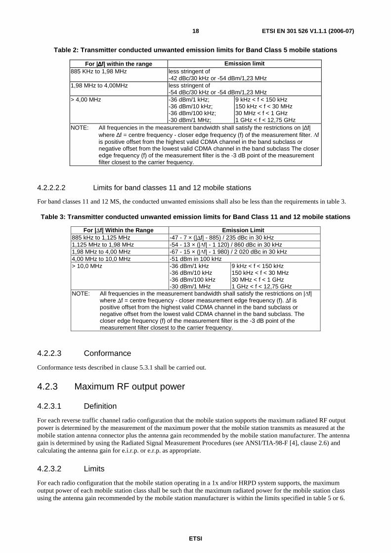


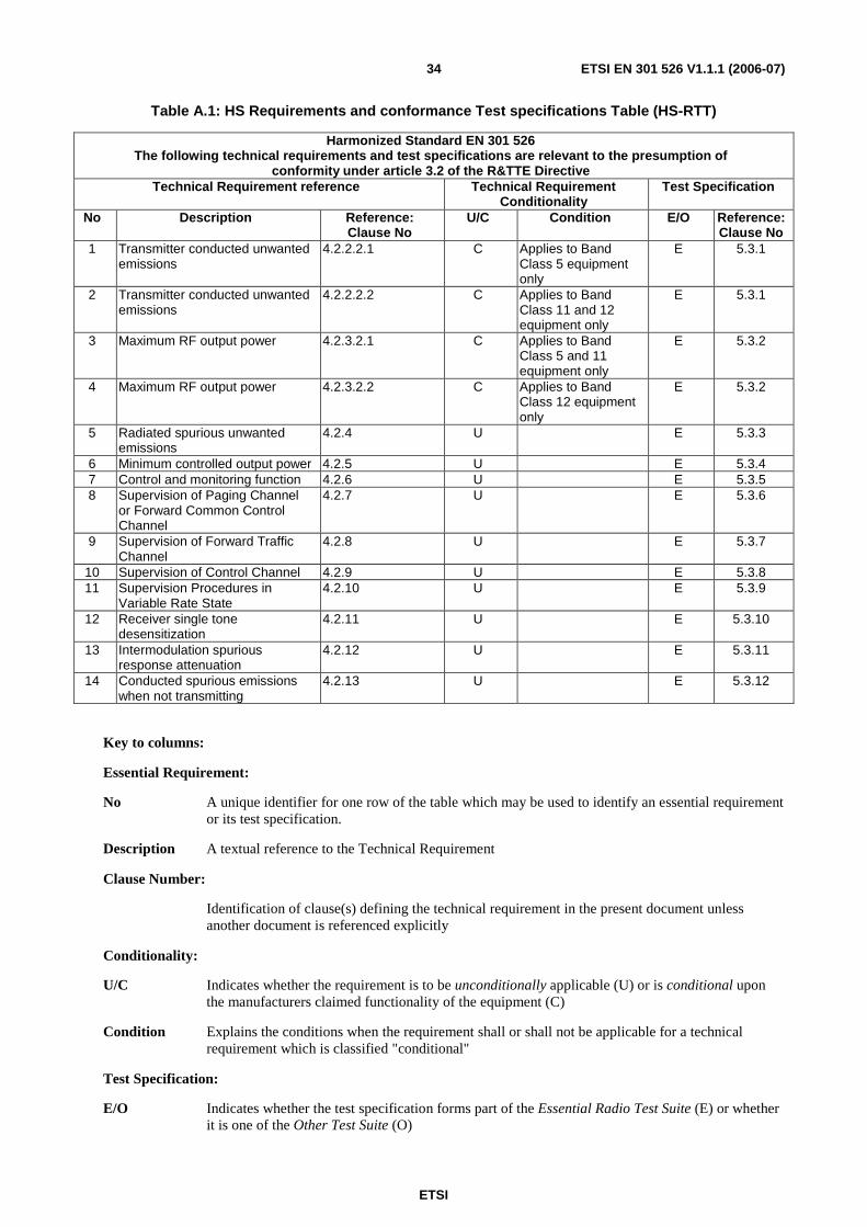


![1st ETSI C-V2X Plugtests Report€¦ · references. [1] ETSI TS 103 301 V1.1.1 (2016-11): "Intelligent Transport Systems (ITS); Vehicular Communications; Basic Set of Applications;](https://static.documents.pub/doc/80x56/5f0c5ac57e708231d434fcd8/1st-etsi-c-v2x-plugtests-report-references-1-etsi-ts-103-301-v111-2016-11.jpg)


