ETSI EN 301 908-1 V11.1.1 (2016-07) IMT cellular networks; Harmonised Standard covering the essential requirements of article 3.2 of the Directive 2014/53/EU; Part 1: Introduction and common requirements HARMONISED EUROPEAN STANDARD
Transcript
ETSI EN 301 908-1 V11.1.1 (2016-07)
IMT cellular networks; Harmonised Standard covering the essential requirements
of article 3.2 of the Directive 2014/53/EU; Part 1: Introduction and common requirements
650 Route des Lucioles F-06921 Sophia Antipolis Cedex - FRANCE
Tel.: +33 4 92 94 42 00 Fax: +33 4 93 65 47 16
Siret N° 348 623 562 00017 - NAF 742 C
Association à but non lucratif enregistrée à la Sous-Préfecture de Grasse (06) N° 7803/88
Important notice
The present document can be downloaded from: http://www.etsi.org/standards-search
The present document may be made available in electronic versions and/or in print. The content of any electronic and/or print versions of the present document shall not be modified without the prior written authorization of ETSI. In case of any
existing or perceived difference in contents between such versions and/or in print, the only prevailing document is the print of the Portable Document Format (PDF) version kept on a specific network drive within ETSI Secretariat.
Users of the present document should be aware that the document may be subject to revision or change of status. Information on the current status of this and other ETSI documents is available at
If you find errors in the present document, please send your comment to one of the following services: https://portal.etsi.org/People/CommiteeSupportStaff.aspx
Copyright Notification
No part may be reproduced or utilized in any form or by any means, electronic or mechanical, including photocopying and microfilm except as authorized by written permission of ETSI.
The content of the PDF version shall not be modified without the written authorization of ETSI. The copyright and the foregoing restriction extend to reproduction in all media.
DECTTM, PLUGTESTSTM, UMTSTM and the ETSI logo are Trade Marks of ETSI registered for the benefit of its Members. 3GPPTM and LTE™ are Trade Marks of ETSI registered for the benefit of its Members and
of the 3GPP Organizational Partners. GSM® and the GSM logo are Trade Marks registered and owned by the GSM Association.
Intellectual Property Rights ................................................................................................................................ 4
5 Testing for compliance with technical requirements .............................................................................. 13
5.1 Environmental conditions for testing ............................................................................................................... 13
5.2 Interpretation of the measurement results ........................................................................................................ 13
5.3 Essential radio test suites .................................................................................................................................. 14
5.3.1.1 Test method ........................................................................................................................................... 14
5.3.1.2 Test configurations ................................................................................................................................ 14
5.3.2 Radiated emissions (BS and repeater) ........................................................................................................ 15
5.3.2.1 Test method ........................................................................................................................................... 15
5.3.2.2 Test configurations ................................................................................................................................ 16
5.3.3 Control and monitoring functions (UE) ...................................................................................................... 16
5.3.3.1 Test method ........................................................................................................................................... 16
Annex A (normative): Relationship between the present document and the essential requirements of Directive 2014/53/EU ......................................................... 18
Annex B (informative): Correct operation of the equipment ............................................................. 19
Annex C (informative): Overview and organization of ETSI EN 301 908 standard parts .............. 20
Annex D (informative): Bibliography ................................................................................................... 24
History .............................................................................................................................................................. 25
ETSI
ETSI EN 301 908-1 V11.1.1 (2016-07)4
Intellectual Property Rights IPRs essential or potentially essential to the present document may have been declared to ETSI. The information pertaining to these essential IPRs, if any, is publicly available for ETSI members and non-members, and can be found in ETSI SR 000 314: "Intellectual Property Rights (IPRs); Essential, or potentially Essential, IPRs notified to ETSI in respect of ETSI standards", which is available from the ETSI Secretariat. Latest updates are available on the ETSI Web server (https://ipr.etsi.org/).
Pursuant to the ETSI IPR Policy, no investigation, including IPR searches, has been carried out by ETSI. No guarantee can be given as to the existence of other IPRs not referenced in ETSI SR 000 314 (or the updates on the ETSI Web server) which are, or may be, or may become, essential to the present document.
Foreword This Harmonised European Standard (EN) has been produced by ETSI Technical Committee Mobile Standards Group (MSG).
For non EU countries the present document may be used for regulatory (Type Approval) purposes.
The present document has been prepared under the Commission's standardisation request C(2015) 5376 final [i.9] to provide one voluntary means of conforming to the essential requirements of Directive 2014/53/EU on the harmonisation of the laws of the Member States relating to the making available on the market of radio equipment and repealing Directive 1999/5/EC [i.1].
Once the present document is cited in the Official Journal of the European Union under that Directive, compliance with the normative clauses of the present document given in table A-1 confers, within the limits of the scope of the present document, a presumption of conformity with the corresponding essential requirements of that Directive, and associated EFTA regulations.
The present document is part 1 of a multi-part deliverable covering the essential requirements under article 3.2 of the Directive 2014/53/EU for Base Stations (BS), Repeaters and User Equipment (UE) for IMT cellular networks, as identified below:
Part 1: "Introduction and common requirements";
Part 2: "CDMA Direct Spread (UTRA FDD) User Equipment (UE)";
Part 3: "CDMA Direct Spread (UTRA FDD) Base Stations (BS)";
Part 4: "CDMA Multi-Carrier (cdma2000) User Equipment (UE)";
Part 5: "CDMA Multi-Carrier (cdma2000) Base Stations (BS)";
Part 6: "CDMA TDD (UTRA TDD) User Equipment (UE)";
Part 7: "CDMA TDD (UTRA TDD) Base Stations (BS)";
Part 8: "Harmonized EN for IMT-2000, TDMA Single-Carrier (UWC 136) (UE) covering essential requirements of article 3.2 of the R&TTE Directive";
Part 9: "Harmonized EN for IMT-2000, TDMA Single-Carrier (UWC 136) (BS) covering essential requirements of article 3.2 of the R&TTE Directive";
Part 10: "Harmonised Standard for IMT-2000, FDMA/TDMA (DECT) covering the essential requirements of article 3.2 of the Directive 2014/53/EU";
Part 11: "CDMA Direct Spread (UTRA FDD) Repeaters";
Part 12: "CDMA Multi-Carrier (cdma2000) Repeaters;
Part 13: "Evolved Universal Terrestrial Radio Access (E-UTRA) User Equipment (UE)";
Part 14: "Evolved Universal Terrestrial Radio Access (E-UTRA) Base Stations (BS)";
Part 15: "Evolved Universal Terrestrial Radio Access (E-UTRA FDD) Repeaters";
Part 16: "Harmonized EN for IMT-2000, Evolved CDMA Multi-Carrier Ultra Mobile Broadband (UMB) (UE) covering the essential requirements of article 3.2 of the R&TTE Directive";
Part 17: "Harmonized EN for IMT-2000, Evolved CDMA Multi-Carrier Ultra Mobile Broadband (UMB) (BS) covering the essential requirements of article 3.2 of the R&TTE Directive";
Part 18: "E-UTRA, UTRA and GSM/EDGE Multi-Standard Radio (MSR) Base Station (BS)";
Part 19: "OFDMA TDD WMAN (Mobile WiMAXTM) TDD User Equipment (UE)";
Part 20: "OFDMA TDD WMAN (Mobile WiMAXTM) TDD Base Station (BS)";
Part 21: "OFDMA TDD WMAN (Mobile WiMAXTM) FDD User Equipment (UE)";
Part 22: "OFDMA TDD WMAN (Mobile WiMAXTM) FDD Base Stations (BS)".
National transposition dates
Date of adoption of this EN: 20 April 2016
Date of latest announcement of this EN (doa): 31 July 2016
Date of latest publication of new National Standard or endorsement of this EN (dop/e):
31 January 2017
Date of withdrawal of any conflicting National Standard (dow): 31 January 2018
Modal verbs terminology In the present document "shall", "shall not", "should", "should not", "may", "need not", "will", "will not", "can" and "cannot" are to be interpreted as described in clause 3.2 of the ETSI Drafting Rules (Verbal forms for the expression of provisions).
"must" and "must not" are NOT allowed in ETSI deliverables except when used in direct citation.
Introduction The present document is part of a set of standards developed by ETSI that are designed to fit in a modular structure to cover radio equipment within the scope of the Radio Equipment Directive [i.1]. The present document is produced following the guidance in ETSI EG 203 336 [i.2] as applicable.
1 Scope The present document applies to user equipment, repeaters and base stations for IMT, falling within the scope of one of the other parts of ETSI EN 301 908 [i.8], except for IMT-2000 FDMA/TDMA (DECT). The present document also covers the corresponding ancillary equipment.
NOTE 1: ETSI EN 301 908-10 [i.7] contains in particular requirements for radiated spurious emissions and control and monitoring functions applicable to IMT-2000 FDMA/TDMA (DECT) equipment.
The present document includes technical requirements which are common to equipment falling within the scope of several of the other parts.
NOTE 2: The other parts of ETSI EN 301 908 [i.8], which are listed in the foreword of the present document, specify technical requirements in respect of a particular type of IMT equipment.
NOTE 3: Recommendations ITU-R M.1457-12 [i.4] and M.2012-1 [i.5] define the characteristics of the members of the IMT-2000 family and IMT-Advanced respectively by means of references to technical specifications developed by Standards Development organizations. The present document applies to equipment designed to meet any version of the terrestrial specifications referenced in Recommendations ITU-R M.1457-12 [i.4] and M.2012-1 [i.5].
The present document contains requirements to demonstrate that radio equipment both effectively uses and supports the efficient use of radio spectrum in order to avoid harmful interference.
2 References
2.1 Normative references References are either specific (identified by date of publication and/or edition number or version number) or non-specific. For specific references, only the cited version applies. For non-specific references, the latest version of the referenced document (including any amendments) applies.
Referenced documents which are not found to be publicly available in the expected location might be found at http://docbox.etsi.org/Reference.
NOTE: While any hyperlinks included in this clause were valid at the time of publication, ETSI cannot guarantee their long term validity.
The following referenced documents are necessary for the application of the present document.
[1] Recommendation ITU-R SM.329-12 (09-2012): "Unwanted emissions in the spurious domain".
[2] ETSI EN 301 502 (V12.5.1) (07-2016): "Global System for Mobile communications (GSM); Base Station (BS) equipment; Harmonised Standard covering the essential requirements of article 3.2 of the Directive 2014/53/EU".
2.2 Informative references References are either specific (identified by date of publication and/or edition number or version number) or non-specific. For specific references, only the cited version applies. For non-specific references, the latest version of the referenced document (including any amendments) applies.
NOTE: While any hyperlinks included in this clause were valid at the time of publication, ETSI cannot guarantee their long term validity.
The following referenced documents are not necessary for the application of the present document but they assist the user with regard to a particular subject area.
[i.1] Directive 2014/53/EU of the European parliament and of the council of 16 April 2014 on the harmonisation of the laws of the Member States relating to the making available on the market of radio equipment and repealing Directive 1999/5/EC.
[i.2] ETSI EG 203 336 (V1.1.1) (08-2015): "Electromagnetic compatibility and Radio spectrum Matters (ERM); Guide for the selection of technical parameters for the production of Harmonised Standards covering article 3.1(b) and article 3.2 of Directive 2014/53/EU".
[i.3] ETSI TR 100 028 (all parts) (V1.4.1): "Electromagnetic compatibility and Radio spectrum Matters (ERM); Uncertainties in the measurement of mobile radio equipment characteristics".
[i.4] Recommendation ITU-R M.1457-12 (2015): "Detailed specifications of the terrestrial radio interfaces of International Mobile Telecommunications-2000 (IMT-2000)".
[i.5] Recommendation ITU-R M.2012-1 (02-2014): "Detailed specifications of the terrestrial radio interfaces of International Mobile Telecommunications-Advanced (IMT-Advanced)".
[i.6] Recommendation ITU-R SM.1539-1 (2002): "Variation of the boundary between the out-of-band and spurious domains required for the application of Recommendations ITU-R SM.1541 and ITU-R SM.329".
[i.7] ETSI EN 301 908-10 (V4.2.1) (10-2015): "Electromagnetic compatibility and Radio spectrum Matters (ERM); Base Stations (BS), Repeaters and User Equipment (UE) for IMT-2000 Third-Generation cellular networks; Part 10: Harmonised Standard for IMT-2000, FDMA/TDMA (DECT) covering the essential requirements of article 3.2 of the Directive 2014/53/EU".
[i.8] ETSI EN 301 908 (all parts): "IMT cellular networks; Harmonised Standard covering the essential requirements of article 3.2 of the Directive 2014/53/EU".
[i.9] Commission Implementing Decision C(2015) 5376 final of 4.8.2015 on a standardisation request to the European Committee for Electrotechnical Standardisation and to the European Telecommunications Standards Institute as regards radio equipment in support of Directive 2014/53/EU of the European Parliament and of the Council.
3 Definitions, symbols and abbreviations
3.1 Definitions For the purposes of the present document, the following terms and definitions apply:
ancillary equipment: equipment (apparatus), used in connection with a User Equipment (UE), Repeater or Base Station (BS) is considered as an ancillary equipment (apparatus) if:
• the equipment is intended for use in conjunction with a user equipment UE, repeater or BS to provide additional operational and/or control features to the radio equipment, (e.g. to extend control to another position or location); and
• the equipment cannot be used on a stand-alone basis to provide user functions independently of a UE, BS or combination of BS and repeater; and
• the UE, BS or combination of BS and repeater to which it is connected, is capable of providing some intended operation, such as transmitting and/or receiving without the ancillary equipment (i.e. it is not a sub-unit of the main equipment essential to the main equipment basic functions).
applicable part: part of the multi-part deliverable, of which the present document is the first part, for which the scope of that document includes the equipment to be tested
Base Station RF bandwidth: bandwidth in which a Base Station transmits and receives multiple carriers and/or RATs simultaneously
ETSI
ETSI EN 301 908-1 V11.1.1 (2016-07)8
channel bandwidth: RF bandwidth supporting a single E-UTRA or [Mobile WiMAXTM] RF carrier with the transmission bandwidth configured in the uplink or downlink of a cell
NOTE: The channel bandwidth is measured in MHz and is used as a reference for transmitter and receiver RF requirements.
enclosure port: physical boundary of the apparatus through which electromagnetic fields may radiate or impinge
NOTE: In the case of integral antenna equipment, this port is inseparable from the antenna port.
environmental profile: range of environmental conditions under which equipment within the scope of the present document is required to comply with the provisions of the present document
idle mode: state of User Equipment (UE) when switched on but with no Radio Resource Control (RRC) connection
IMT-2000: mobile systems as defined in Recommendation ITU-R M.1457-12 [i.4]
NOTE: Recommendation ITU-R M.1457-12 [i.4] identifies the detailed specifications for the IMT-2000 radio interfaces.
IMT-Advanced: mobile systems as defined in Recommendation ITU-R M.2012-1 [i.5]
NOTE: Recommendation ITU-R M.2012-1 [i.5] identifies the detailed specifications for the IMT-Advanced radio interfaces.
Lower RF bandwidth edge: frequency of the lower edge of the Base Station RF bandwidth, used as a frequency reference point for transmitter and receiver requirements
MSR Base Station: Base Station characterized by the ability of its receiver and transmitter to process two or more carriers in common active RF components simultaneously in a declared RF bandwidth, where at least one carrier is of a different RAT than the other carrier(s)
multi-band Base Station: Base Station characterized by the ability of its transmitter and/or receiver to process two or more carriers in common active RF components simultaneously, where at least one carrier is configured at a different non-overlapping operating band than the other carrier(s)
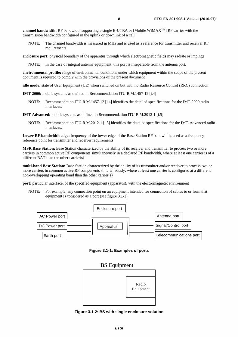
port: particular interface, of the specified equipment (apparatus), with the electromagnetic environment
NOTE: For example, any connection point on an equipment intended for connection of cables to or from that equipment is considered as a port (see figure 3.1-1).
Figure 3.1-1: Examples of ports
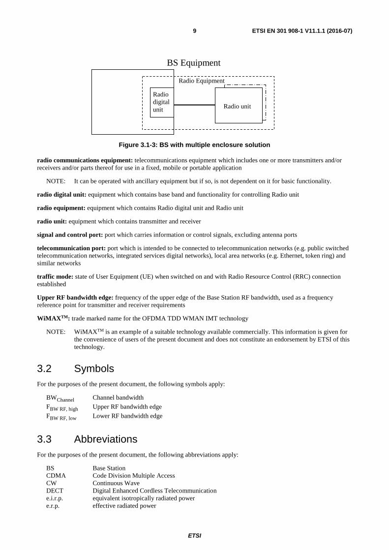
Figure 3.1-2: BS with single enclosure solution
Enclosure port
Apparatus
DC Power port
AC Power port
Earth port
Antenna port
Signal/Control port Telecommunications port
Radio Equipment
BS Equipment
ETSI
ETSI EN 301 908-1 V11.1.1 (2016-07)9
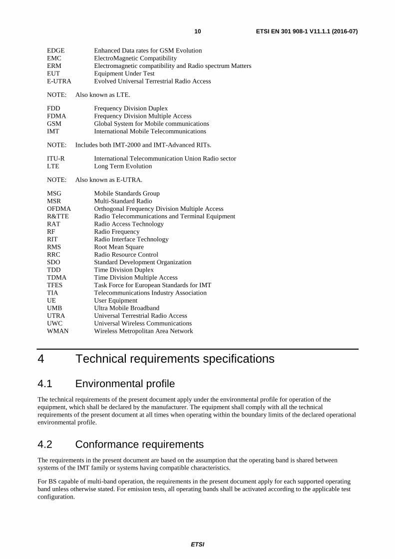
Figure 3.1-3: BS with multiple enclosure solution
radio communications equipment: telecommunications equipment which includes one or more transmitters and/or receivers and/or parts thereof for use in a fixed, mobile or portable application
NOTE: It can be operated with ancillary equipment but if so, is not dependent on it for basic functionality.
radio digital unit: equipment which contains base band and functionality for controlling Radio unit
radio equipment: equipment which contains Radio digital unit and Radio unit
radio unit: equipment which contains transmitter and receiver
signal and control port: port which carries information or control signals, excluding antenna ports
telecommunication port: port which is intended to be connected to telecommunication networks (e.g. public switched telecommunication networks, integrated services digital networks), local area networks (e.g. Ethernet, token ring) and similar networks
traffic mode: state of User Equipment (UE) when switched on and with Radio Resource Control (RRC) connection established
Upper RF bandwidth edge: frequency of the upper edge of the Base Station RF bandwidth, used as a frequency reference point for transmitter and receiver requirements
WiMAXTM: trade marked name for the OFDMA TDD WMAN IMT technology
NOTE: WiMAXTM is an example of a suitable technology available commercially. This information is given for the convenience of users of the present document and does not constitute an endorsement by ETSI of this technology.
3.2 Symbols For the purposes of the present document, the following symbols apply:
3.3 Abbreviations For the purposes of the present document, the following abbreviations apply:
BS Base Station CDMA Code Division Multiple Access CW Continuous Wave DECT Digital Enhanced Cordless Telecommunication e.i.r.p. equivalent isotropically radiated power e.r.p. effective radiated power
Radio digital unit
Radio Equipment
Radio unit
BS Equipment
ETSI
ETSI EN 301 908-1 V11.1.1 (2016-07)10
EDGE Enhanced Data rates for GSM Evolution EMC ElectroMagnetic Compatibility ERM Electromagnetic compatibility and Radio spectrum Matters EUT Equipment Under Test E-UTRA Evolved Universal Terrestrial Radio Access
NOTE: Also known as LTE.
FDD Frequency Division Duplex FDMA Frequency Division Multiple Access GSM Global System for Mobile communications IMT International Mobile Telecommunications
NOTE: Includes both IMT-2000 and IMT-Advanced RITs.
ITU-R International Telecommunication Union Radio sector LTE Long Term Evolution
NOTE: Also known as E-UTRA.
MSG Mobile Standards Group MSR Multi-Standard Radio OFDMA Orthogonal Frequency Division Multiple Access R&TTE Radio Telecommunications and Terminal Equipment RAT Radio Access Technology RF Radio Frequency RIT Radio Interface Technology RMS Root Mean Square RRC Radio Resource Control SDO Standard Development Organization TDD Time Division Duplex TDMA Time Division Multiple Access TFES Task Force for European Standards for IMT TIA Telecommunications Industry Association UE User Equipment UMB Ultra Mobile Broadband UTRA Universal Terrestrial Radio Access UWC Universal Wireless Communications WMAN Wireless Metropolitan Area Network
4 Technical requirements specifications
4.1 Environmental profile The technical requirements of the present document apply under the environmental profile for operation of the equipment, which shall be declared by the manufacturer. The equipment shall comply with all the technical requirements of the present document at all times when operating within the boundary limits of the declared operational environmental profile.
4.2 Conformance requirements The requirements in the present document are based on the assumption that the operating band is shared between systems of the IMT family or systems having compatible characteristics.
For BS capable of multi-band operation, the requirements in the present document apply for each supported operating band unless otherwise stated. For emission tests, all operating bands shall be activated according to the applicable test configuration.
ETSI
ETSI EN 301 908-1 V11.1.1 (2016-07)11
4.2.1 Introduction
To meet the essential requirement under article 3.2 of Radio Equipment Directive 2014/53/EU [i.1] for IMT equipment three common essential parameters have been identified. Tables 4.2.1-1 and 4.2.1-2 provide cross-references, for UE, repeater and BS respectively, between these essential parameters and the corresponding technical requirements for equipment within the scope of the present document.
Table 4.2.1-1: Cross references for User Equipment (UE)
Essential parameter Corresponding technical requirements Corresponding test suite Radiated emissions 4.2.2 Radiated emissions (UE) 5.3.1 Control and monitoring functions 4.2.4 Control and monitoring functions (UE) 5.3.3
Table 4.2.1-2: Cross references for Base Stations (BS), and repeaters
Essential parameter Corresponding technical requirements Corresponding test suite Radiated emissions 4.2.3 Radiated emissions (BS and repeater) 5.3.2
NOTE: The use of correct timing and correct code are covered in annex B.
4.2.2 Radiated emissions (UE)
4.2.2.1 Definition
This test assesses the ability of radio communications equipment and ancillary equipment to limit unwanted emissions from the enclosure port.
This test is applicable to radio communications equipment and ancillary equipment.
This test shall be performed on the radio communications equipment and/or a representative configuration of the ancillary equipment.
4.2.2.2 Limits
The frequency boundary and reference bandwidths for the detailed transitions of the limits between the requirements for out-of-band emissions and spurious emissions are based on Recommendations ITU-R SM.329-12 [1] and SM.1539-1 [i.6].
The requirements shown in table 4.2.2.2-1 are only applicable for frequencies in the spurious domain.
fc - 2,5 × BWChannel MHz < f < fc + 2,5 × BWChannel MHz
Not defined E-UTRA FDD, E-UTRA TDD, Mobile WiMAXTM
fc - 2,5 × 10 MHz < f < fc1 + 2,5 × 10 MHz
Not defined UTRA TDD, 7,68 Mcps option
fc - 4 MHz < f < fc + 4 MHz Not defined UTRA TDD, 1,28 Mcps option cdma2000, spreading rate 1
NOTE: fc is the UE transmit centre frequency.
ETSI
ETSI EN 301 908-1 V11.1.1 (2016-07)12
4.2.2.3 Conformance
Conformance tests described in clause 5.3.1 shall be carried out.
4.2.3 Radiated emissions (BS and repeater)
4.2.3.1 Definition
This test assesses the ability of BS and repeater to limit unwanted emission from the enclosure port.
This test is applicable to Base Stations, except for BS that are only single-RAT GSM/EDGE capable and also applicable to repeaters. This test shall be performed on a representative configuration of the equipment under test. For a BS with multiple enclosures, the BS part with Radio digital unit and the Radio unit may be tested separately.
For Base Stations that are only single-RAT GSM/EDGE capable, the limits and the test method in clauses 4.2.16 and 5.3.16 of ETSI EN 301 502 [2] shall apply.
4.2.3.2 Limits
The frequency boundary and reference bandwidths for the detailed transitions of the limits between the requirements for out-of-band emissions and spurious emissions are based on Recommendations ITU-R SM.329-12 [1] and SM.1539-1 [i.6].
The requirements, shown in table 4.2.3.2-1, are applicable for frequencies in the spurious domain.
The BS and repeater shall meet the limits given in table 4.2.3.2-1.
Table 4.2.3.2-1: Radiated spurious emissions requirements (BS and repeater)
Frequency Minimum requirement (e.r.p.)/ reference bandwidth
Applicability
30 MHz ≤ f < 1 000 MHz -36 dBm/100 kHz All 1 GHz ≤ f < 12,75 GHz -30 dBm/1 MHz All
Fc1 - 2,5 × 5 MHz < f < Fc2 + 2,5 × 5 MHz Not defined UTRA FDD, UTRA TDD, 3,84 Mcps option, cdma2000, spreading rate 3
Fc1 - 2,5 × 10 MHz < f < Fc2 + 2,5 × 10 MHz Not defined UTRA TDD, 7,68 Mcps option Fc1 - 2,5 × BWChannel MHz < f < Fc2 + 2,5 ×
BWChannel MHz Not defined E-UTRA FDD, E-UTRA TDD, Mobile
WiMAXTM (BWChannel ≥ 2,5 MHz)
FBW RF, low - 10 MHz < f < FBW RF, high
+ 10 MHz (see note)
Not defined E-UTRA, UTRA and GSM/EDGE Multi-Standard Radio (MSR) Base Stations Multi-Band Multi-Standard Radio
Fc1 - 4 MHz < f < Fc2 + 4 MHz Not defined UTRA TDD, 1,28 Mcps option, cdma2000, spreading rate 1 (BWChannel = 1,25 MHz)
Fc1 - 500 kHz < f < Fc2 + 500 kHz Not defined UWC 136, 200 kHz option Fc1 - 250 kHz < f < Fc2 + 250 kHz Not defined UWC 136, 30 kHz option
NOTE: For BS capable of multi-band operation, the frequency ranges relating to the carriers of all bands shall apply.
Key:
Fc1: Centre frequency of first carrier frequency used by the BS and repeater.
Fc2: Centre frequency of last carrier frequency used by the BS and repeater.
BWChannel: Channel BandWidth.
FBW RF, high: Upper RF bandwidth edge.
ETSI
ETSI EN 301 908-1 V11.1.1 (2016-07)13
FBW RF, low: Lower RF bandwidth edge.
4.2.3.3 Conformance
Conformance tests described in clause 5.3.2 shall be carried out.
4.2.4 Control and monitoring functions (UE)
4.2.4.1 Definition
This requirement, together with other control and monitoring technical requirements identified in the table of cross references in the applicable part, verifies that the control and monitoring functions of the UE prevent it from transmitting in the absence of a valid network.
This test is applicable to radio communications equipment and ancillary equipment in the operating band defined in the applicable part of this multi-part harmonised standard.
This test shall be performed on the radio communications equipment and/or a representative configuration of the ancillary equipment.
4.2.4.2 Limits
The maximum measured power during the duration of the test shall not exceed -30 dBm.
4.2.4.3 Conformance
Conformance tests described in clause 5.3.3 shall be carried out.
5 Testing for compliance with technical requirements
5.1 Environmental conditions for testing Tests defined in the present document shall be carried out at representative points within the boundary limits of the declared operational environmental profile.
Where technical performance varies subject to environmental conditions, tests shall be carried out under a sufficient variety of environmental conditions (within the boundary limits of the declared operational environmental profile) to give confidence of compliance for the affected technical requirements.
Normally it should be sufficient for all tests to be conducted using normal test conditions except where otherwise stated. For guidance on other test conditions to be used, see the applicable Part for details.
5.2 Interpretation of the measurement results The interpretation of the results recorded in a test report for the measurements described in the present document shall be as follows:
• the measured value related to the corresponding limit will be used to decide whether an equipment meets the requirements of the present document;
• the value of the measurement uncertainty for the measurement of each parameter shall be included in the test report;
• the recorded value of the measurement uncertainty shall be, for each measurement, equal to or lower than the figures in table 5.2-1 for UE and table 5.2-2 for BS and repeater;
ETSI
ETSI EN 301 908-1 V11.1.1 (2016-07)14
For the test methods, according to the present document, the measurement uncertainty figures shall be calculated and shall correspond to an expansion factor (coverage factor) k = 1,96 (which provides a confidence level of 95 % in the case where the distributions characterizing the actual measurement uncertainties are normal (Gaussian)). Principles for the calculation of measurement uncertainty are contained in ETSI TR 100 028 [i.3], in particular in annex D of the ETSI TR 100 028-2 [i.3].
Tables 5.2-1 and 5.2-2 are based on such expansion factors.
Table 5.2-1: Maximum measurement uncertainty (UE)
Parameter Uncertainty Effective radiated RF power between 30 MHz and 180 MHz ±6 dB Effective radiated RF power between 180 MHz and 12,75 GHz ±3 dB Conducted RF power ±1 dB
Table 5.2-2: Maximum measurement uncertainty (BS and repeater)
Parameter Uncertainty for EUT dimension ≤ 1 m
Uncertainty for EUT dimension > 1 m
Effective radiated RF power between 30 MHz to 180 MHz ±6 dB ±6 dB Effective radiated RF power between 180 MHz to 4 GHz ±4 dB ±6 dB Effective radiated RF power between 4 GHz to 12,75 GHz ±6 dB ±9 dB (see note) Conducted RF power ±1 dB ±1 dB NOTE: This value may be reduced to ±6 dB when further information on the potential radiation characteristic of the
EUT is available.
NOTE: If the test system for a test is known to have a measurement uncertainty greater than that specified in tables 5.2-1 or 5.2-2, this equipment can still be used, provided that an adjustment is made follows:
� Any additional uncertainty in the test system over and above that specified in tables 5.2-1 or 5.2-2 is used to tighten the test requirements - making the test harder to pass (for some tests, e.g. receiver tests, this may require modification of stimulus signals). This procedure will ensure that a test system not compliant with tables 5.2-1 or 5.2-2 does not increase the probability of passing an EUT that would otherwise have failed a test if a test system compliant with tables 5.2-1 or 5.2-2 had been used.
5.3 Essential radio test suites
5.3.1 Radiated emissions (UE)
5.3.1.1 Test method
Whenever possible the test site should be a fully anechoic chamber simulating the free-space conditions. EUT shall be placed on a non-conducting support. Mean power of any spurious components shall be detected by the test antenna and measuring receiver (e.g. a spectrum analyser).
At each frequency at which a component is detected, the EUT shall be rotated to obtain maximum response, and the effective radiated power (e.r.p.) of that component determined by a substitution measurement, which shall be the reference method. The measurement shall be repeated with the test antenna in the orthogonal polarization plane. Test systems are allowed to be pre-substituted by carrying out the substitution measurement for each frequency and by recording the obtained value into test system software as a correction factor.
NOTE: Effective radiated power (e.r.p.) refers to the radiation of a half wave tuned dipole instead of an isotropic antenna. There is a constant difference of 2,15 dB between e.i.r.p. and e.r.p. e.r.p. (dBm) = e.i.r.p. (dBm) - 2,15 (Recommendation ITU-R SM.329-12 [1], annex 1).
Measurements are made with a tuned dipole antenna or a reference antenna with a known gain referenced to an isotropic antenna. Unless otherwise stated, all measurements are done as mean power (RMS).
ETSI
ETSI EN 301 908-1 V11.1.1 (2016-07)15
If a different test site or method is used, this shall be stated in the test report. The results shall be converted to the reference method values and the validity of the conversion shall be demonstrated.
5.3.1.2 Test configurations
This clause defines the configurations for emission tests as follows:
• the equipment shall be tested under normal test conditions;
• the test configuration shall be as close to normal intended use as possible;
• if the equipment is part of a system, or can be connected to ancillary equipment, then it shall be acceptable to test the equipment while connected to the minimum configuration of ancillary equipment necessary to exercise the ports;
• if the equipment has a large number of ports, then a sufficient number shall be selected to simulate actual operation conditions and to ensure that all the different types of termination are tested;
• the test conditions, test configuration and mode of operation shall be recorded in the test report;
• ports which in normal operation are connected shall be connected to an ancillary equipment or to a representative piece of cable correctly terminated to simulate the input/output characteristics of the ancillary equipment, RF input/output ports shall be correctly terminated;
• ports that are not connected to cables during normal operation, e.g. service connectors, programming connectors; temporary connectors, etc. shall not be connected to any cables for the purpose of this test. Where cables have to be connected to these ports, or interconnecting cables have to be extended in length in order to exercise the EUT, precautions shall be taken to ensure that the evaluation of the EUT is not affected by the addition or extension of these cables:
- emission tests shall be performed in two modes of operation:
� with a communication link established (traffic mode); and
� in the idle mode;
• the traffic mode configuration which uses the UE maximum output power for testing shall be declared by the manufacturer.
Ancillary equipment shall be tested with it connected to a UE in which case compliance shall be demonstrated to the appropriate clauses of the present document.
The results obtained shall be compared to the limits in clause 4.2.2.2 in order to prove compliance.
5.3.2 Radiated emissions (BS and repeater)
5.3.2.1 Test method
a) A test site fulfilling the requirements of Recommendation ITU-R SM.329-12 [1] shall be used. The EUT shall be placed on a non-conducting support and shall be operated from a power source via a RF filter to avoid radiation from the power leads.
Mean power of any spurious components shall be detected by the test antenna and measuring receiver (e.g. a spectrum analyser). At each frequency at which a component is detected, the EUT shall be rotated and the height of the test antenna adjusted to obtain maximum response, and the effective radiated power (e.r.p.) of that component determined by a substitution measurement. The measurement shall be repeated with the test antenna in the orthogonal polarization plane. Test systems are allowed to be pre-substituted by carrying out the substitution measurement for each frequency and by recording the obtained value into test system software as a correction factor.
NOTE: Effective radiated power (e.r.p.) refers to the radiation of a half wave tuned dipole instead of an isotropic antenna. There is a constant difference of 2,15 dB between e.i.r.p. and e.r.p. e.r.p. (dBm) = e.i.r.p. (dBm) - 2,15 (Recommendation ITU-R SM.329-12 [1], annex 1).
ETSI
ETSI EN 301 908-1 V11.1.1 (2016-07)16
b) The BS shall transmit with maximum power declared by the manufacturer with all transmitters active. Set the Base Station to transmit a signal as defined in the applicable part for measurement of spurious emissions.
In case of a repeater the gain and the output power shall be adjusted to the maximum value as declared by the manufacturer. Use an input signal as defined in the applicable part for the measurement of spurious emissions.
c) The video bandwidth shall be approximately three times the resolution bandwidth. If this video bandwidth is not available on the measuring receiver, it shall be the maximum available and at least 1 MHz. Unless otherwise stated, all measurements are done as mean power (RMS). The received power shall be measured over the frequency ranges and using the measurement bandwidth as defined in table 4.2.3.2-1.
5.3.2.2 Test configurations
This clause defines the configurations for emission tests as follows:
• the equipment shall be tested under normal test conditions as specified in the functional standards;
• the test configuration shall be as close to normal intended use as possible;
• if the equipment is part of a system, or can be connected to ancillary equipment, then it shall be acceptable to test the equipment while connected to the minimum configuration of ancillary equipment necessary to exercise the ports;
• if the equipment has a large number of ports, then a sufficient number shall be selected to simulate actual operation conditions and to ensure that all the different types of termination are tested;
• the test conditions, test configuration and mode of operation shall be recorded in the test report;
• ports which in normal operation are connected shall be connected to an ancillary equipment or to a representative piece of cable correctly terminated to simulate the input/output characteristics of the ancillary equipment, Radio Frequency (RF) input/output ports shall be correctly terminated;
• ports which are not connected to cables during normal operation, e.g. service connectors, programming connectors, temporary connectors, etc. Shall not be connected to any cables for the purpose of this test. Where cables have to be connected to these ports, or interconnecting cables have to be extended in length in order to exercise the EUT, precautions shall be taken to ensure that the evaluation of the EUT is not affected by the addition or extension of these cables.
For an EUT which contains more than one BS, it is sufficient to perform tests relating to connectors of each representative type of the BS forming part of the EUT.
For an EUT which contains more than one repeater, it is sufficient to perform tests relating to connectors of each representative type of the repeater forming part of the EUT.
At the manufacturer's discretion the test may be performed on the ancillary equipment separately or a representative configuration of the combination of radio and ancillary equipment. In each case the EUT is tested against all applicable emission clauses of the present document and in each case, compliance enables the ancillary equipment to be used with different radio equipment.
The results obtained shall be compared to the limits in clause 4.2.3.2 in order to prove compliance.
5.3.3 Control and monitoring functions (UE)
5.3.3.1 Test method
a) At the start of the test, the UE shall be switched off. The UE antenna connector shall be connected to a power measuring equipment, with the following characteristics:
- the RF bandwidth shall exceed the total operating transmit frequency range of the UE for operation with an applicable part;
- the response time of the power measuring equipment shall be such that the measured power has reached within 1 dB of its steady state value within 100 µs of a CW signal being applied;
ETSI
ETSI EN 301 908-1 V11.1.1 (2016-07)17
- it shall record the maximum power measured.
NOTE: The equipment may include a video low pass filter to minimize its response to transients or Gaussian noise peaks.
b) The UE shall be switched on for a period of approximately fifteen minutes, and then switched off.
c) The EUT shall remain switched off for a period of at least thirty seconds, and shall then be switched on for a period of approximately one minute.
d) The maximum power emitted from the UE throughout the duration of the test shall be recorded.
The results obtained shall be compared to the limits in clause 4.2.4.2 in order to prove compliance.
ETSI
ETSI EN 301 908-1 V11.1.1 (2016-07)18
Annex A (normative): Relationship between the present document and the essential requirements of Directive 2014/53/EU The present document has been prepared under the Commission's standardisation request C(2015) 5376 final [i.9] to provide one voluntary means of conforming to the essential requirements of Directive 2014/53/EU on the harmonisation of the laws of the Member States relating to the making available on the market of radio equipment and repealing Directive 1999/5/EC [i.1].
Once the present document is cited in the Official Journal of the European Union under that Directive, compliance with the normative clauses of the present document given in table A-1 confers, within the limits of the scope of the present document, a presumption of conformity with the corresponding essential requirements of that Directive, and associated EFTA regulations.
Table A-1: Relationship between the present document and the essential requirements of Directive 2014/53/EU
Harmonised Standard ETSI EN 301 908-1 The following requirements are relevant to the presumption of conformity
under the article 3.2 of Directive 2014/53/EU [i.1] Requirement Requirement Conditionality
No Description Reference: Clause No U/C Condition
1 Radiated emissions (UE) 4.2.2 U 2 Radiated emissions (BS and
repeater) 4.2.3 U
3 Control and monitoring functions (UE)
4.2.4 U
Key to columns:
Requirement:
No A unique identifier for one row of the table which may be used to identify a requirement.
Description A textual reference to the requirement.
Clause Number Identification of clause(s) defining the requirement in the present document unless another document is referenced explicitly.
Requirement Conditionality:
U/C Indicates whether the requirement shall be unconditionally applicable (U) or is conditional upon the manufacturer's claimed functionality of the equipment (C).
Condition Explains the conditions when the requirement shall or shall not be applicable for a requirement which is classified "conditional".
Presumption of conformity stays valid only as long as a reference to the present document is maintained in the list published in the Official Journal of the European Union. Users of the present document should consult frequently the latest list published in the Official Journal of the European Union.
Other Union legislation may be applicable to the product(s) falling within the scope of the present document.
ETSI
ETSI EN 301 908-1 V11.1.1 (2016-07)19
Annex B (informative): Correct operation of the equipment In a radio communications system, it is essential that certain functions of equipment operate correctly, in order to prevent harmful interference to other users of the radio spectrum. These functions can include transmission on the correct frequency, at the correct time and/or using the correct code (for equipment using CDMA). For the BS, the parameters of these functions are commanded by the network, and for the UE they are commanded by the BS.
Several of the tests in the applicable parts implicitly require a connection to be established between the Equipment Under Test (EUT) and the test apparatus. This implicitly requires the EUT to respond correctly to the commands it receives.
It is considered that the establishment of a connection demonstrates that the equipment meets most aspects of correct functioning to meet the essential requirements under article 3.2 of the Radio Equipment Directive 2014/53/EU [i.1]. Tests for certain specific functions are defined in applicable parts, where these functions are critical to the prevention of harmful interference.
Therefore, the explicit tests for correct functioning of the equipment, together with the implicit testing through the ability to establish a connection, are sufficient to meet the essential requirement for correct functioning of the equipment so as to prevent harmful interference, under article 3.2 of the Radio Equipment Directive 2014/53/EU [i.1].
ETSI
ETSI EN 301 908-1 V11.1.1 (2016-07)20
Annex C (informative): Overview and organization of ETSI EN 301 908 standard parts This annex provides an overview of the following IMT technologies included in the multi-part standard ETSI EN 301 908 [i.8] and how the different standard parts map to the terrestrial components of IMT-2000 and IMT Advanced. IMT is specified by ITU-R in Recommendation M.1457-12 [i.4] and contains the following terrestrial IMT-2000 component radio interfaces:
• IMT-2000 CDMA Direct Spread.
• IMT-2000 CDMA Multi-Carrier.
• IMT-2000 CDMA TDD.
• IMT-2000 TDMA Single-Carrier.
• IMT-2000 FDMA/TDMA.
• IMT-2000 OFDMA TDD WMAN.
IMT-Advanced is specified by ITU-R in Recommendation M.2012-1 [i.5] and contains the following terrestrial IMT-Advanced radio interfaces:
• LTE-Advanced.
• Wireless MAN-Advanced.
ETSI EN 301 908 [i.8] is a multi-part deliverable covering Base Stations (BS), Repeaters and User Equipment (UE) for the members of the terrestrial component of the IMT family. Further details of the standard parts are given below.
NOTE: This annex only includes the parts that received support for the creation of ETSI work items under the Commission's standardisation request C(2015) 5376 final [i.9] at the date of finalization of the present document.
A cross-reference table for the standards parts applicable to the IMT terrestrial component radio access technologies is given in table C-1 and a frequency band cross reference table is given in table C-2. The scope, content and relation between the standard parts are given in the clauses below.
ETSI
ETSI EN 301 908-1 V11.1.1 (2016-07)21
Table C-1: IMT Radio Interface Technologies in ETSI EN 301 908 [i.8] and the corresponding standard parts
IMT-2000/ IMT-Advanced terrestrial RIT
(as identified by ITU-R)
[i.4] and [i.5]
RIT name (as identified by
the SDO)
Reference SDO
Equipment type
ETSI EN 301 908 [i.8] part covering the RIT and equipment type
Notes
IMT-2000 CDMA Direct Spread
UTRA FDD ETSI (3GPP) UE Part 2 BS Part 3
Repeater Part 11 E-UTRA FDD ETSI (3GPP) UE Part 13
BS Part 14 Repeater Part 15
LTE-Advanced E-UTRA FDD ETSI (3GPP) UE Part 13 BS Part 14
Repeater Part 15 IMT-2000 CDMA Multi-Carrier
Cdma2000 TIA (3GPP2)
Repeater Part 12
IMT-2000 CDMA TDD
E-UTRA TDD ETSI (3GPP) UE Part 13 BS Part 14 BS Part 18
IMT-2000 FDMA/TDMA
DECT ETSI (DECT) - Part 10
IMT-2000 CDMA Direct Spread, LTE-Advanced and IMT-2000 CDMA TDD
UTRA FDD/TDD E-UTRA and GSM/EDGE
ETSI (3GPP) BS Part 18 Covers multi-RAT capable (MSR) BS, including GSM/EDGE operation. GSM/EDGE single RAT capable BS is covered by ETSI EN 301 502 [2]
IMT-2000 OFDMA TDD WMAN
Mobile WiMAXTM TDD component
IEEE/ WiMAX Forum®
UE Part 19
BS Part 20
Mobile WiMAXTM FDD component
IEEE/ WiMAX Forum®
UE Part 21
BS Part 22
Table C-2: Frequency band cross reference table for IMT Radio Interface Technologies in ETSI EN 301 908 [i.8]
UTRA FDD Band
UTRA TDD Band
(Note 2)
E-UTRA Band
CDMA2000 Band Class
Mobile WiMAXTM
Band Class
Frequency Range
I - 1 6 - 1 920 MHz to 1 980 MHz paired with 2 110 MHz to 2 170 MHz
III - 3 8 6C 1 710 MHz to 1 785 MHz paired with 1 805 MHz to 1 880 MHz
VII - 7 13 - 2 500 MHz to 2 570 MHz paired with 2 620 MHz to 2 690 MHz
VIII - 8 9 7G 880 MHz to 915 MHz paired with 925 MHz to 960 MHz
XV - - - - 1 900 MHz to 1 920 MHz paired with 2 600 MHz to 2 620 MHz
XVI - - - - 2 010 MHz to 2 025 MHz paired with 2 585 MHz to 2 600 MHz
XX - 20 - - 832 MHz to 862 MHz paired with 791 MHz to 821 MHz
XXII - 22 - - 3 410 MHz to 3 490 MHz paired with 3 510 MHz to 3 590 MHz
- - 28 - - 703 MHz to 748 MHz 758 MHz to 803 MHz
XXIII - 32 - - 1 452 MHz to 1 496 MHz - a 33 - - 1 900 MHz to 1 920 MHz - a 34 - - 2 010 MHz to 2 025 MHz
NOTE 1: The technical specifications identify additional frequency bands not currently included within ETSI EN 301 908 [i.8].
NOTE 2: The UTRA TDD bands are referenced for multi-RAT capable (MSR) BS in part 18.
ETSI EN 301 908 [i.8] is divided into multiple standard parts as follows:
Part 1: Introduction and common requirements The scope of Part 1 is common technical requirements for the IMT RITs, except for IMT-2000 FDMA/TDMA. This includes radiated emissions (UE, BS and repeater) and Control and monitoring functions (UE).
Part 2: CDMA Direct Spread (UTRA FDD) User Equipment (UE) The scope of Part 2 is User Equipment for IMT-2000 CDMA Direct Spread, which includes UTRA FDD as defined by ETSI (3GPP).
Part 3: CDMA Direct Spread (UTRA FDD) Base Stations (BS) The scope of Part 3 is Base Stations for IMT-2000 CDMA Direct Spread, which includes UTRA FDD as defined by ETSI (3GPP).
Part 10: IMT-2000 FDMA/TDMA (DECT) The scope of Part 10 is equipment for IMT-2000 TDMA FDMA/TDMA, which includes DECT as defined by ETSI (DECT), including radiated spurious emission and Control and monitoring function.
Part 11: CDMA Direct Spread (UTRA FDD) (Repeaters) The scope of Part 11 is Repeaters for IMT-2000 CDMA Direct Spread, which includes UTRA FDD as defined by ETSI (3GPP).
Part 12: IMT-2000 CDMA Multi Carrier (cdma2000) (Repeaters) The scope of Part 12 is Repeaters for IMT-2000 CDMA Multi-Carrier, which includes cdma2000 as defined by TIA (3GPP2).
Part 13: Evolved Universal Terrestrial Radio Access (E-UTRA) (UE) The scope of Part 13 is User Equipment for E-UTRA as defined by ETSI (3GPP).
Part 14: Evolved Universal Terrestrial Radio Access (E-UTRA) (BS) The scope of Part 14 is Base Stations for E-UTRA as defined by ETSI (3GPP).
Part 15: Evolved Universal Terrestrial Radio Access (E-UTRA FDD) (Repeaters) The scope of Part 15 is Repeaters for E-UTRA (FDD) as defined by ETSI (3GPP).
Part 18: E-UTRA, UTRA and GSM/EDGE Multi-Standard Radio (MSR) Base Stations (BS) The scope of Part 18 is Multi-Standard Radio capable Base stations (E-UTRA, UTRA, GSM/EDGE) as defined by ETSI (3GPP).
Part 19: OFDMA TDD WMAN (Mobile WiMAXTM) TDD User Equipment (UE) The scope of Part 19 is User Equipment for OFDMA TDD WMAN (Mobile WiMAXTM) operating in TDD mode as defined by IEEE / WiMAX Forum®.
Part 20: OFDMA TDD WMAN (Mobile WiMAXTM) TDD Base Stations (BS) The scope of Part 20 is Base stations for OFDMA TDD WMAN (Mobile WiMAXTM) operating in TDD mode as defined by IEEE / WiMAX Forum®.
Part 21: OFDMA TDD WMAN (Mobile WiMAXTM) FDD User Equipment (UE) The scope of Part 21 is User Equipment for OFDMA TDD WMAN Mobile WiMAXTM (FDD) as defined by IEEE / WiMAX Forum®.
ETSI
ETSI EN 301 908-1 V11.1.1 (2016-07)23
Part 22: OFDMA TDD WMAN (Mobile WiMAXTM) FDD Base Stations (BS) The scope of Part 22 is Base Station for OFDMA TDD WMAN Mobile WiMAXTM (FDD) as defined by IEEE / WiMAX Forum®.
ETSI
ETSI EN 301 908-1 V11.1.1 (2016-07)24
Annex D (informative): Bibliography Directive 2004/108/EC of the European Parliament and of the Council of 15 December 2004 on the approximation of the laws of the Member States relating to electromagnetic compatibility and repealing Directive 89/336/EEC (text with EEA relevance (EMC Directive)).
Directive 2006/95/EC of the European Parliament and of the Council of 12 December 2006 on the harmonisation of the laws of Member States relating to electrical equipment designed for use within certain voltage limits (LV Directive).
CEPT/ERC/REC 74-01 (Siófok 98, Nice 99, Sesimbra 02, Hradec Kralove 05, Cardiff 11): "Unwanted Emissions in the Spurious Domain".
ETSI EN 301 489 (all parts): "Electromagnetic compatibility and Radio spectrum Matters (ERM); ElectroMagnetic Compatibility (EMC) standard for radio equipment and services".
ETSI
ETSI EN 301 908-1 V11.1.1 (2016-07)25
History
Document history
V1.1.1 January 2002 Publication
V2.2.1 October 2003 Publication
V3.2.1 May 2007 Publication
V4.2.1 March 2010 Publication
V5.2.1 May 2011 Publication
V6.2.1 April 2013 Publication
V7.1.1 March 2015 Publication
V11.0.1 January 2016 EN Approval Procedure AP 20160420: 2016-01-21 to 2016-04-20