ETSI EN 301 908-19 V6.3.1 (2016-05) IMT cellular networks; Harmonised Standard covering the essential requirements of article 3.2 of the Directive 2014/53/EU; Part 19: OFDMA TDD WMAN (Mobile WiMAX TM ) TDD User Equipment (UE) HARMONISED EUROPEAN STANDARD
Transcript
ETSI EN 301 908-19 V6.3.1 (2016-05)
IMT cellular networks; Harmonised Standard covering the essential requirements
of article 3.2 of the Directive 2014/53/EU; Part 19: OFDMA TDD WMAN (Mobile WiMAXTM)
TDD User Equipment (UE)
HARMONISED EUROPEAN STANDARD
ETSI
ETSI EN 301 908-19 V6.3.1 (2016-05)2
Reference REN/MSG-TFES-11-19-RED
Keywords IMT, IMT-2000, mobile, OFDMA, radio,
regulation, TDD, WiMAX, WMAN
ETSI
650 Route des Lucioles F-06921 Sophia Antipolis Cedex - FRANCE
Tel.: +33 4 92 94 42 00 Fax: +33 4 93 65 47 16
Siret N° 348 623 562 00017 - NAF 742 C
Association à but non lucratif enregistrée à la Sous-Préfecture de Grasse (06) N° 7803/88
Important notice
The present document can be downloaded from: http://www.etsi.org/standards-search
The present document may be made available in electronic versions and/or in print. The content of any electronic and/or print versions of the present document shall not be modified without the prior written authorization of ETSI. In case of any
existing or perceived difference in contents between such versions and/or in print, the only prevailing document is the print of the Portable Document Format (PDF) version kept on a specific network drive within ETSI Secretariat.
Users of the present document should be aware that the document may be subject to revision or change of status. Information on the current status of this and other ETSI documents is available at
If you find errors in the present document, please send your comment to one of the following services: https://portal.etsi.org/People/CommiteeSupportStaff.aspx
Copyright Notification
No part may be reproduced or utilized in any form or by any means, electronic or mechanical, including photocopying and microfilm except as authorized by written permission of ETSI.
The content of the PDF version shall not be modified without the written authorization of ETSI. The copyright and the foregoing restriction extend to reproduction in all media.
DECTTM, PLUGTESTSTM, UMTSTM and the ETSI logo are Trade Marks of ETSI registered for the benefit of its Members. 3GPPTM and LTE™ are Trade Marks of ETSI registered for the benefit of its Members and
of the 3GPP Organizational Partners. GSM® and the GSM logo are Trade Marks registered and owned by the GSM Association.
4.2.0 General ........................................................................................................................................................ 10
5 Testing for compliance with technical requirements .............................................................................. 20
5.1 Environmental conditions for testing ............................................................................................................... 20
5.2 Product information .......................................................................................................................................... 20
5.3 Interpretation of the measurement results ........................................................................................................ 20
5.4 Essential radio test suites .................................................................................................................................. 21
5.4.1 Transmitter Maximum and Minimum Output Power ................................................................................. 21
5.4.1.1 Method of measurement ........................................................................................................................ 21
5.4.1.2 Test requirements .................................................................................................................................. 22
5.4.2.2 Test requirements .................................................................................................................................. 24
5.4.3.2 Test requirements .................................................................................................................................. 25
5.4.4.2 Test requirements .................................................................................................................................. 26
5.4.5.2 Test requirements .................................................................................................................................. 28
5.4.6.2 Test requirements .................................................................................................................................. 29
5.4.7.2 Test requirements .................................................................................................................................. 30
5.4.8.2 Test requirements .................................................................................................................................. 31
5.4.9 Transmitter Adjacent Channel Leakage Power Ratio ................................................................................. 31
5.4.9.1 Method of measurement ........................................................................................................................ 31
5.4.9.2 Test requirements .................................................................................................................................. 33
5.4.10.1 Method of test ....................................................................................................................................... 33
5.4.10.2 Test requirement ................................................................................................................................... 33
Annex A (normative): Relationship between the present document and the essential requirements of Directive 2014/53/EU ......................................................... 34
Annex B (normative): Environmental profile ................................................................................... 36
Annex C (informative): Void ................................................................................................................. 37
Annex D (informative): Bibliography ................................................................................................... 38
History .............................................................................................................................................................. 39
ETSI
ETSI EN 301 908-19 V6.3.1 (2016-05)6
Intellectual Property Rights IPRs essential or potentially essential to the present document may have been declared to ETSI. The information pertaining to these essential IPRs, if any, is publicly available for ETSI members and non-members, and can be found in ETSI SR 000 314: "Intellectual Property Rights (IPRs); Essential, or potentially Essential, IPRs notified to ETSI in respect of ETSI standards", which is available from the ETSI Secretariat. Latest updates are available on the ETSI Web server (https://ipr.etsi.org/).
Pursuant to the ETSI IPR Policy, no investigation, including IPR searches, has been carried out by ETSI. No guarantee can be given as to the existence of other IPRs not referenced in ETSI SR 000 314 (or the updates on the ETSI Web server) which are, or may be, or may become, essential to the present document.
Foreword This Harmonised European Standard (EN) has been produced by ETSI Technical Committee Mobile Standards Group (MSG).
The present document has been prepared under the Commission's standardisation request C(2015) 5376 final [i.8] to provide one voluntary means of conforming to the essential requirements of Directive 2014/53/EU on the harmonisation of the laws of the Member States relating to the making available on the market of radio equipment and repealing Directive 1999/5/EC [i.2].
Once the present document is cited in the Official Journal of the European Union under that Directive, compliance with the normative clauses of the present document given in table A-1 confers, within the limits of the scope of the present document, a presumption of conformity with the corresponding essential requirements of that Directive, and associated EFTA regulations.
The present document is part 19 of a multi-part deliverable. Full details of the entire series can be found in part 1 [i.9].
National transposition dates
Date of adoption of this EN: 20 April 2016
Date of latest announcement of this EN (doa): 31 July 2016
Date of latest publication of new National Standard or endorsement of this EN (dop/e):
31 January 2017
Date of withdrawal of any conflicting National Standard (dow): 31 January 2018
Modal verbs terminology In the present document "shall", "shall not", "should", "should not", "may", "need not", "will", "will not", "can" and "cannot" are to be interpreted as described in clause 3.2 of the ETSI Drafting Rules (Verbal forms for the expression of provisions).
"must" and "must not" are NOT allowed in ETSI deliverables except when used in direct citation.
Introduction The present document is part of a set of standards developed by ETSI that are designed to fit in a modular structure to cover radio equipment within the scope of the Radio Equipment Directive [i.2]. The present document is produced following the guidance in ETSI EG 203 336 [i.3] as applicable.
1 Scope The present document applies to the following radio equipment type:
• User Equipment for IMT-2000 OFDMA TDD WMAN (Mobile WiMAXTM) operating in TDD mode.
This radio equipment type is capable of operating in all or any part of the frequency bands given in table 1-1.
Table 1-1: OFDMA TDD WMAN User Equipment frequency bands
Mobile WiMAXTM Band Class Index
IMT-2000 OFDMA TDD WMAN service operating bands
Channel Bandwidth
1.B 2 300 MHz to 2 400 MHz 5 MHz and 10 MHz 3.A 2 500 MHz to 2 690 MHz 5 MHz and 10 MHz 5L.A 3 400 MHz to 3 600 MHz 5 MHz 5L.C 3 400 MHz to 3 600 MHz 10 MHz 5H.A 3 600 MHz to 3 800 MHz 5 MHz 5H.C 3 600 MHz to 3 800 MHz 10 MHz
The present document contains requirements to demonstrate that Radio equipment both effectively uses and supports the efficient use of radio spectrum in order to avoid harmful interference.
In addition to the present document, other ENs that specify technical requirements in respect of essential requirements under other parts of article 3 of the Radio Equipment Directive 2014/53/EU [i.2] may apply to equipment within the scope of the present document.
NOTE: A list of such ENs is included on the web site http://www.newapproach.org.
2 References
2.1 Normative references References are either specific (identified by date of publication and/or edition number or version number) or non-specific. For specific references, only the cited version applies. For non-specific references, the latest version of the referenced document (including any amendments) applies.
Referenced documents which are not found to be publicly available in the expected location might be found at http://docbox.etsi.org/Reference.
NOTE: While any hyperlinks included in this clause were valid at the time of publication, ETSI cannot guarantee their long term validity.
The following referenced documents are necessary for the application of the present document.
[1] WMF-T25-002-R010v06 (2012): "WiMAX Forum® Test Procedures - Mobile Radio Conformance Tests" - Release 1 v0.6.
[2] CEPT/ERC/Recommendation 74-01E (Edition of January, 2011) (Siófok 98, Nice 99, Sesimbra 02, Hradec Kralove 05, Cardiff 11): "Unwanted emissions in the spurious domain".
2.2 Informative references References are either specific (identified by date of publication and/or edition number or version number) or non-specific. For specific references, only the cited version applies. For non-specific references, the latest version of the referenced document (including any amendments) applies.
NOTE: While any hyperlinks included in this clause were valid at the time of publication, ETSI cannot guarantee their long term validity.
The following referenced documents are not necessary for the application of the present document but they assist the user with regard to a particular subject area.
[i.1] Recommendation ITU-R SM.329-12 (2012): "Unwanted emissions in the spurious domain".
[i.2] Directive 2014/53/EU of the European Parliament and of the Council of 16 April 2014 on the harmonisation of the laws of the Member States relating to the making available on the market of radio equipment and repealing Directive 1999/5/EC (Text with EEA relevance).
[i.3] ETSI EG 203 336 (V1.1.1) (2015): "Electromagnetic compatibility and Radio spectrum Matters (ERM); Guide for the selection of technical parameters for the production of Harmonised Standards covering article 3.1(b) and article 3.2 of Directive 2014/53/EU".
[i.4] ETSI TR 102 215 (V1.3.1): "Electromagnetic compatibility and Radio spectrum Matters (ERM); Recommended approach, and possible limits for measurement uncertainty for the measurement of radiated electromagnetic fields above 1 GHz".
[i.5] ETSI EN 300 019-1-0: "Environmental Engineering (EE); Environmental conditions and environmental tests for telecommunications equipment; Part 1-0: Classification of environmental conditions; Introduction".
[i.6] ETSI TR 100 028 (all parts) (V1.4.1): "Electromagnetic compatibility and Radio spectrum Matters (ERM); Uncertainties in the measurement of mobile radio equipment characteristics".
[i.7] Void.
[i.8] Commission Implementing Decision C(2015) 5376 final of 4.8.2015 on a standardisation request to the European Committee for Electrotechnical Standardisation and to the European Telecommunications Standards Institute as regards radio equipment in support of Directive 2014/53/EU of the European Parliament and of the Council.
[i.9] ETSI EN 301 908-1 (V11.1.1): "IMT cellular networks; Harmonised Standard covering the essential requirements of article 3.2 of the Directive 2014/53/EU; Part 1: Introduction and common requirements".
3 Definitions, symbols and abbreviations
3.1 Definitions For the purposes of the present document, the terms and definitions given in Directive 2014/53/EU [i.2] and the following apply:
burst: period during which radio waves are intentionally transmitted, preceded and succeeded by periods during which no intentional transmission is made
environmental profile: declared range of environmental conditions under which equipment within the scope of the present document is required to be compliant
integral antenna: antenna which is declared to be part of the radio equipment by the manufacturer
NOTE: Even when equipment with an integral antenna is concerned, it might still be possible to separate the antenna from the equipment using a special tool. In such cases, the assessment of the radio equipment and of the antenna against requirements of the present document may be done separately.
maximum output power: mean power level per carrier of the base station measured at the antenna connector in a specified reference condition
mean power: power (transmitted or received) in a bandwidth when applied to a modulated signal
nominal maximum output power: maximum nominal mean power level per carrier of the user equipment available at the antenna connector declared by the manufacturer; for equipment implementing dynamic change of modulation format, it is intended as the maximum nominal mean power associated to the modulation format delivering the highest power
receiver thermal noise power: equal to k×T×BW×F
ETSI
ETSI EN 301 908-19 V6.3.1 (2016-05)9
WiMAXTM: trademarked name for the OFDMA TDD WMAN IMT technology
NOTE: WiMAXTM is an example of a suitable technology available commercially. This information is given for the convenience of users of the present document and does not constitute an endorsement by ETSI of this technology.
3.2 Symbols For the purposes of the present document, the following symbols apply:
ABS Base Station Interface A
AMS Mobile Station Interface A
AUUT Unit Under Test Interface A
BW Assigned channel bandwidth dB Decibel dBc Decibel relative to carrier dBm Decibel relative to 1 milliwatt f Frequency of measurement fc Centre frequency of the assigned channel
F Receiver noise figure GHz GigaHertz k Boltzmann's constant MBS Base Station Interface M
MHz MegaHertz MMS Mobile Station Interface M
N Maximum number of antennas in a multiple antenna configuration Nth Receiver thermal noise power expressed in dBm
PSENS Receiver sensitivity level at BER ≤ 10-6 (or equivalent PER) performance, corresponding to the
most robust modulation and coding rate supported by the technology PSENS5 Receiver sensitivity level at BER 10-6 for a 5 MHz channelized system, corresponding to the most
robust modulation and coding rate supported by the technology PSENS10 Receiver sensitivity level at BER 10-6 for a 10 MHz channelized system, corresponding to the
most robust modulation and coding rate supported by the technology Pnom Declared nominal maximum output Power
T Ambient temperature in Kelvin
3.3 Abbreviations For the purposes of the present document, the following abbreviations apply:
ACLR Adjacent Channel Leakage power Ratio ACS Adjacent Channel Selectivity BCI Band Class Index BER Bit Error Ratio BS Base Station CW Continuous Wave EFTA European Free Trade Association ERM Electromagnetic compatibility and Radio spectrum Matters EUT Equipment Under Test IMT International Mobile Telecommunications MSG Mobile Standards Group OFDMA Orthogonal Frequency Division Multiple Access PER Packet Error Ratio / Rate RED Radio Equipment Directive RF Radio Frequency RMS Root Mean Square RRC Root Raised Cosine TDD Time Division Duplexing TFES Task Force for European Standards for IMT
ETSI
ETSI EN 301 908-19 V6.3.1 (2016-05)10
UE User Equipment UUT Unit Under Test WMAN Wireless Metropolitan Area Network
4 Technical requirements specification
4.1 Environmental profile The technical requirements of the present document apply under the environmental profile for operation of the equipment, which shall be declared by the supplier. The equipment shall comply with all the technical requirements of the present document at all times when operating within the boundary limits of the declared operational environmental profile.
4.2 Conformance requirements
4.2.0 General
This clause describes the conformance requirements for OFDMA TDD WMAN User Equipment (UE).
4.2.1 Introduction
To meet the essential requirement under article 3.2 of Directive 2014/53/EU [i.2] (Radio Equipment Directive) for IMT-2000 User Equipment (UE), a set of essential parameters in addition to those in ETSI EN 301 908-1 [i.9] have been identified. Table 4.2.1-1 provides a cross reference between these essential parameters and the corresponding technical requirements for equipment within the scope of the present document.
Table 4.2.1-1: Cross references
Essential parameter Corresponding technical requirements Corresponding test suite
Transmitter spectrum mask 4.2.3 Transmitter Spectrum emission mask 5.4.2 Transmitter unwanted emissions in the out of band domain
4.2.11 Transmitter adjacent channel leakage power ratio 5.4.9
Transmitter unwanted emissions in the spurious domain
4.2.4 Transmitter spurious emissions 5.4.3
Transmitter power limits 4.2.2 Transmitter maximum output power 5.4.1 4.2.5 Transmitter minimum output power 5.4.1
Receiver unwanted emissions in the spurious domain
Unless otherwise stated, the transmitter and receiver characteristics are specified at the antenna connector(s) of the UE. For UE(s) with an integral antenna only, a reference antenna(s) with a gain of 0 dBi should be assumed for each antenna port(s). A UE with integral antenna(s) may be taken into account by converting these power levels into field strength requirements, assuming a 0 dBi gain antenna.
4.2.2 Transmitter Maximum Output Power
4.2.2.1 Definition
The UE maximum output power is measured over total allocated channel bandwidth available at the antenna connector.
ETSI
ETSI EN 301 908-19 V6.3.1 (2016-05)11
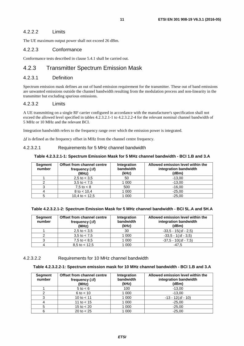
4.2.2.2 Limits
The UE maximum output power shall not exceed 26 dBm.
4.2.2.3 Conformance
Conformance tests described in clause 5.4.1 shall be carried out.
4.2.3 Transmitter Spectrum Emission Mask
4.2.3.1 Definition
Spectrum emission mask defines an out of band emission requirement for the transmitter. These out of band emissions are unwanted emissions outside the channel bandwidth resulting from the modulation process and non-linearity in the transmitter but excluding spurious emissions.
4.2.3.2 Limits
A UE transmitting on a single RF carrier configured in accordance with the manufacturer's specification shall not exceed the allowed level specified in tables 4.2.3.2.1-1 to 4.2.3.2.2-4 for the relevant nominal channel bandwidth of 5 MHz or 10 MHz and the relevant BCI.
Integration bandwidth refers to the frequency range over which the emission power is integrated.
∆f is defined as the frequency offset in MHz from the channel centre frequency.
4.2.3.2.1 Requirements for 5 MHz channel bandwidth
Table 4.2.3.2.1-1: Spectrum Emission Mask for 5 MHz channel bandwidth - BCI 1.B and 3.A
Segment number
Offset from channel centre frequency (Δf)
(MHz)
Integration bandwidth
(kHz)
Allowed emission level within the integration bandwidth
(dBm) 1 2,5 to < 3,5 50 -13,00 2 3,5 to < 7,5 1 000 -13,00 3 7,5 to < 8 500 -16,00 4 8 to < 10,4 1 000 -25,00 5 10,4 to < 12,5 1 000 -25,00
Table 4.2.3.2.1-2: Spectrum Emission Mask for 5 MHz channel bandwidth - BCI 5L.A and 5H.A
Segment number
Offset from channel centre frequency (Δf)
(MHz)
Integration bandwidth
(kHz)
Allowed emission level within the integration bandwidth
Conformance tests described in clause 5.4.2 shall be carried out.
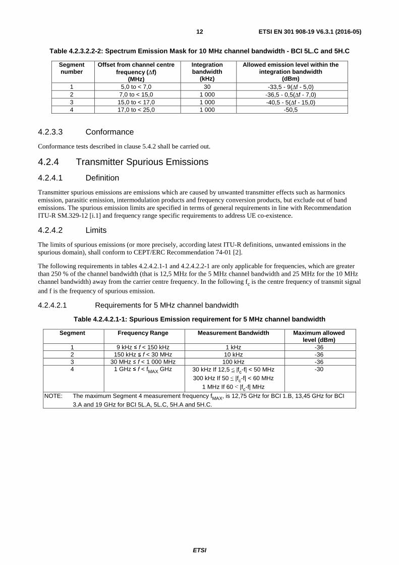
4.2.4 Transmitter Spurious Emissions
4.2.4.1 Definition
Transmitter spurious emissions are emissions which are caused by unwanted transmitter effects such as harmonics emission, parasitic emission, intermodulation products and frequency conversion products, but exclude out of band emissions. The spurious emission limits are specified in terms of general requirements in line with Recommendation ITU-R SM.329-12 [i.1] and frequency range specific requirements to address UE co-existence.
4.2.4.2 Limits
The limits of spurious emissions (or more precisely, according latest ITU-R definitions, unwanted emissions in the spurious domain), shall conform to CEPT/ERC Recommendation 74-01 [2].
The following requirements in tables 4.2.4.2.1-1 and 4.2.4.2.2-1 are only applicable for frequencies, which are greater than 250 % of the channel bandwidth (that is 12,5 MHz for the 5 MHz channel bandwidth and 25 MHz for the 10 MHz channel bandwidth) away from the carrier centre frequency. In the following fc is the centre frequency of transmit signal
and f is the frequency of spurious emission.
4.2.4.2.1 Requirements for 5 MHz channel bandwidth
Table 4.2.4.2.1-1: Spurious Emission requirement for 5 MHz channel bandwidth
Segment Frequency Range Measurement Bandwidth Maximum allowed level (dBm)
300 kHz If 100 ≤ |fc-f| < 120 MHz 1 MHz If 120 ≤ |fc-f| MHz
-30
NOTE: The maximum Segment 4 measurement frequency fMAX, is 12,75 GHz for BCI 1.B, 13,45 GHz for
BCI 3.A and 19 GHz for BCI 5L.A, 5L.C, 5H.A and 5H.C.
4.2.4.2.3 Requirements for UE Coexistence
Table 4.2.4.2.3-1: Spurious Emission requirement for UE coexistence
Applicable BCI Spurious frequency (f) range (MHz)
Measurement bandwidth (MHz)
Maximum Emission Level (dBm)
1.B, 5L.A, 5L.C, 5H.A and 5H.C
2 110 ≤ f < 2 170 1 -50
1.B, 5L.A, 5L.C, 5H.A and 5H.C
1 805 ≤ f < 1 880 1 -50
1.B, 5L.A, 5L.C, 5H.A and 5H.C
2 496 ≤ f < 2 690 1 -50
1.B, 5L.A, 5L.C, 5H.A and 5H.C
925 ≤ f < 960 1 -50
1.B, 5L.A, 5L.C, 5H.A and 5H.C
1 900 ≤ f < 1 920 1 -50
1.B, 5L.A, 5L.C, 5H.A and 5H.C
2 010 ≤ f < 2 025 1 -50
1.B, 5L.A, 5L.C, 5H.A and 5H.C
2 570 ≤ f < 2 620 1 -50
1.B, 5L.A, 5L.C, 5H.A and 5H.C
791 ≤ f < 821 1 -50
3.A 2 620 ≤ f < 2 690 1 -40
4.2.4.3 Conformance
Conformance tests described in clause 5.4.3 shall be carried out.
4.2.5 Transmitter Minimum Output Power
4.2.5.1 Definition
The UE minimum output power is measured over total allocated channel bandwidth available at the antenna connector when the power is set to the minimum value.
4.2.5.2 Limits
The UE minimum output power shall not exceed -19 dBm.
4.2.5.3 Conformance
Conformance tests described in clause 5.4.1 shall be carried out.
ETSI
ETSI EN 301 908-19 V6.3.1 (2016-05)14
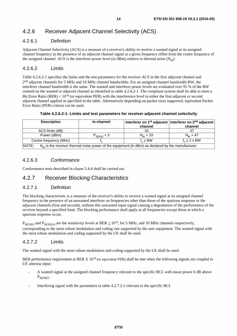
4.2.6 Receiver Adjacent Channel Selectivity (ACS)
4.2.6.1 Definition
Adjacent Channel Selectivity (ACS) is a measure of a receiver's ability to receive a wanted signal at its assigned channel frequency in the presence of an adjacent channel signal at a given frequency offset from the centre frequency of the assigned channel. ACS is the interferer power level (in dBm) relative to thermal noise (Nth).
4.2.6.2 Limits
Table 4.2.6.2-1 specifies the limits and the test parameters for the receiver ACS in the first adjacent channel and 2nd adjacent channels for 5 MHz and 10 MHz channel bandwidths. For an assigned channel bandwidth BW, the interferer channel bandwidth is the same. The wanted and interferer power levels are evaluated over 95 % of the BW centred on the wanted or adjacent channel as identified in table 4.2.6.2-1. The compliant system shall be able to meet a Bit Error Ratio (BER) < 10-6 (or equivalent PER) with the interference level in either the first adjacent or second adjacent channel applied as specified in the table. Alternatively depending on packet sizes supported, equivalent Packet Error Ratio (PER) criteria can be used.
Table 4.2.6.2-1: Limits and test parameters for receiver adjacent channel selectivity
Description In-channel Interferer on 1st adjacent channel
NOTE: Nth is the receiver thermal noise power of the equipment (in dBm) as declared by the manufacturer.
4.2.6.3 Conformance
Conformance tests described in clause 5.4.4 shall be carried out.
4.2.7 Receiver Blocking Characteristics
4.2.7.1 Definition
The blocking characteristic is a measure of the receiver's ability to receive a wanted signal at its assigned channel frequency in the presence of an unwanted interferer on frequencies other than those of the spurious response or the adjacent channels (first and second), without this unwanted input signal causing a degradation of the performance of the receiver beyond a specified limit. The blocking performance shall apply at all frequencies except those at which a spurious response occur.
PSENS5 and PSENS10 are the sensitivity levels at BER ≤ 10-6, for 5 MHz, and 10 MHz channels respectively,
corresponding to the most robust modulation and coding rate supported by the user equipment. The wanted signal with the most robust modulation and coding supported by the UE shall be used.
4.2.7.2 Limits
The wanted signal with the most robust modulation and coding supported by the UE shall be used.
BER performance requirement at BER ≤ 10-6 (or equivalent PER) shall be met when the following signals are coupled to UE antenna input:
- A wanted signal at the assigned channel frequency relevant to the specific BCI, with mean power 6 dB above PSENS5.
- Interfering signal with the parameters in table 4.2.7.2-1 relevant to the specific BCI.
ETSI
ETSI EN 301 908-19 V6.3.1 (2016-05)15
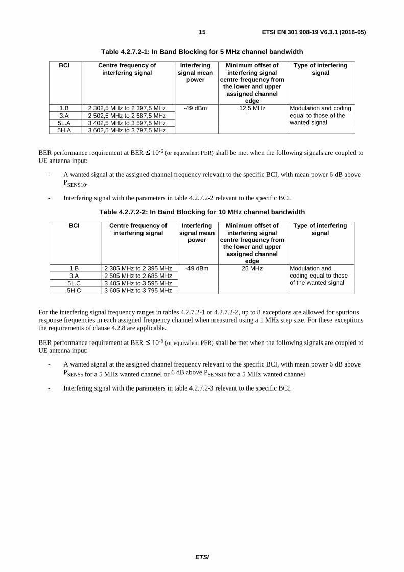
Table 4.2.7.2-1: In Band Blocking for 5 MHz channel bandwidth
BCI Centre frequency of interfering signal
Interfering signal mean
power
Minimum offset of interfering signal
centre frequency from the lower and upper assigned channel
edge
Type of interfering signal
1.B 2 302,5 MHz to 2 397,5 MHz -49 dBm 12,5 MHz Modulation and coding equal to those of the wanted signal
3.A 2 502,5 MHz to 2 687,5 MHz 5L.A 3 402,5 MHz to 3 597,5 MHz 5H.A 3 602,5 MHz to 3 797,5 MHz
BER performance requirement at BER ≤ 10-6 (or equivalent PER) shall be met when the following signals are coupled to UE antenna input:
- A wanted signal at the assigned channel frequency relevant to the specific BCI, with mean power 6 dB above PSENS10.
- Interfering signal with the parameters in table 4.2.7.2-2 relevant to the specific BCI.
Table 4.2.7.2-2: In Band Blocking for 10 MHz channel bandwidth
BCI Centre frequency of interfering signal
Interfering signal mean
power
Minimum offset of interfering signal
centre frequency from the lower and upper assigned channel
edge
Type of interfering signal
1.B 2 305 MHz to 2 395 MHz -49 dBm 25 MHz Modulation and coding equal to those of the wanted signal
3.A 2 505 MHz to 2 685 MHz 5L.C 3 405 MHz to 3 595 MHz 5H.C 3 605 MHz to 3 795 MHz
For the interfering signal frequency ranges in tables 4.2.7.2-1 or 4.2.7.2-2, up to 8 exceptions are allowed for spurious response frequencies in each assigned frequency channel when measured using a 1 MHz step size. For these exceptions the requirements of clause 4.2.8 are applicable.
BER performance requirement at BER ≤ 10-6 (or equivalent PER) shall be met when the following signals are coupled to UE antenna input:
- A wanted signal at the assigned channel frequency relevant to the specific BCI, with mean power 6 dB above PSENS5 for a 5 MHz wanted channel or 6 dB above PSENS10 for a 5 MHz wanted channel.
- Interfering signal with the parameters in table 4.2.7.2-3 relevant to the specific BCI.
ETSI
ETSI EN 301 908-19 V6.3.1 (2016-05)16
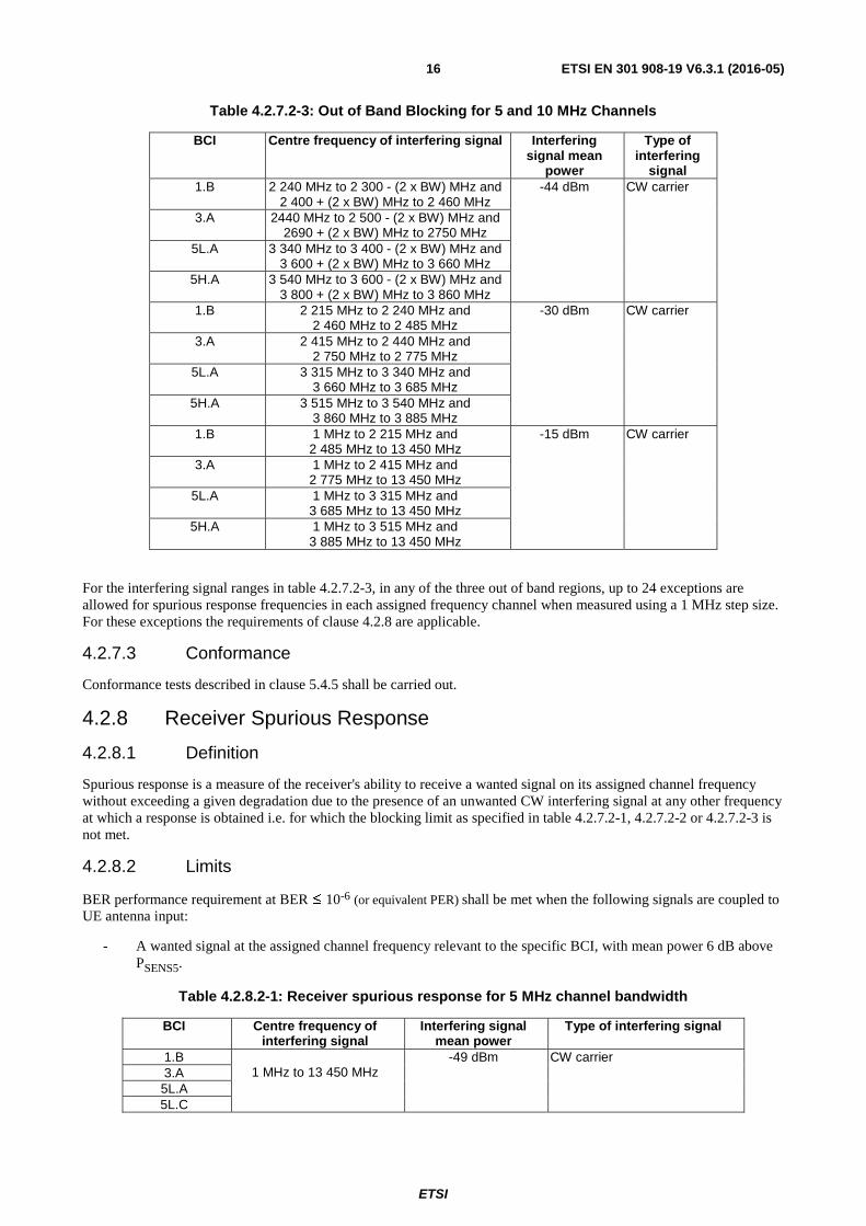
Table 4.2.7.2-3: Out of Band Blocking for 5 and 10 MHz Channels
BCI Centre frequency of interfering signal Interfering signal mean
power
Type of interfering
signal 1.B 2 240 MHz to 2 300 - (2 x BW) MHz and
2 400 + (2 x BW) MHz to 2 460 MHz -44 dBm CW carrier
3.A 2440 MHz to 2 500 - (2 x BW) MHz and 2690 + (2 x BW) MHz to 2750 MHz
5L.A 3 340 MHz to 3 400 - (2 x BW) MHz and 3 600 + (2 x BW) MHz to 3 660 MHz
5H.A 3 540 MHz to 3 600 - (2 x BW) MHz and 3 800 + (2 x BW) MHz to 3 860 MHz
1.B 2 215 MHz to 2 240 MHz and 2 460 MHz to 2 485 MHz
-30 dBm CW carrier
3.A 2 415 MHz to 2 440 MHz and 2 750 MHz to 2 775 MHz
5L.A 3 315 MHz to 3 340 MHz and 3 660 MHz to 3 685 MHz
5H.A 3 515 MHz to 3 540 MHz and 3 860 MHz to 3 885 MHz
1.B 1 MHz to 2 215 MHz and 2 485 MHz to 13 450 MHz
-15 dBm CW carrier
3.A 1 MHz to 2 415 MHz and 2 775 MHz to 13 450 MHz
5L.A 1 MHz to 3 315 MHz and 3 685 MHz to 13 450 MHz
5H.A 1 MHz to 3 515 MHz and 3 885 MHz to 13 450 MHz
For the interfering signal ranges in table 4.2.7.2-3, in any of the three out of band regions, up to 24 exceptions are allowed for spurious response frequencies in each assigned frequency channel when measured using a 1 MHz step size. For these exceptions the requirements of clause 4.2.8 are applicable.
4.2.7.3 Conformance
Conformance tests described in clause 5.4.5 shall be carried out.
4.2.8 Receiver Spurious Response
4.2.8.1 Definition
Spurious response is a measure of the receiver's ability to receive a wanted signal on its assigned channel frequency without exceeding a given degradation due to the presence of an unwanted CW interfering signal at any other frequency at which a response is obtained i.e. for which the blocking limit as specified in table 4.2.7.2-1, 4.2.7.2-2 or 4.2.7.2-3 is not met.
4.2.8.2 Limits
BER performance requirement at BER ≤ 10-6 (or equivalent PER) shall be met when the following signals are coupled to UE antenna input:
- A wanted signal at the assigned channel frequency relevant to the specific BCI, with mean power 6 dB above PSENS5.
Table 4.2.8.2-1: Receiver spurious response for 5 MHz channel bandwidth
BCI Centre frequency of interfering signal
Interfering signal mean power
Type of interfering signal
1.B 1 MHz to 13 450 MHz
-49 dBm CW carrier 3.A 5L.A 5L.C
ETSI
ETSI EN 301 908-19 V6.3.1 (2016-05)17
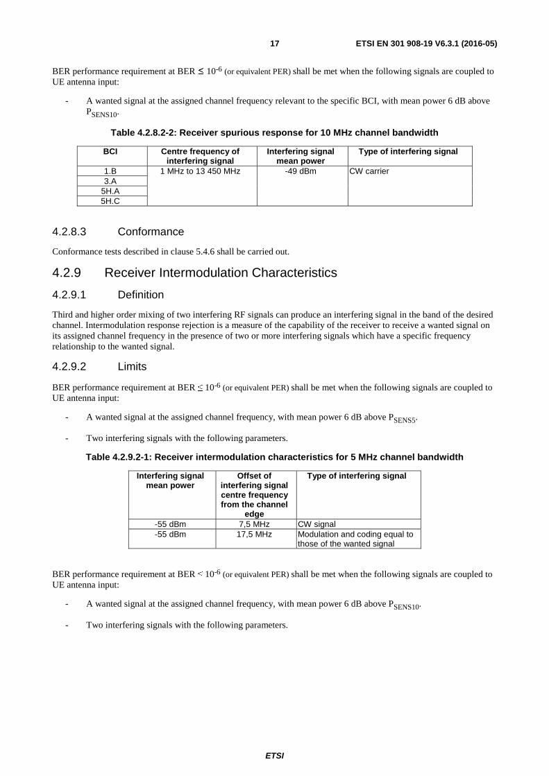
BER performance requirement at BER ≤ 10-6 (or equivalent PER) shall be met when the following signals are coupled to UE antenna input:
- A wanted signal at the assigned channel frequency relevant to the specific BCI, with mean power 6 dB above PSENS10.
Table 4.2.8.2-2: Receiver spurious response for 10 MHz channel bandwidth
BCI Centre frequency of interfering signal
Interfering signal mean power
Type of interfering signal
1.B 1 MHz to 13 450 MHz
-49 dBm CW carrier 3.A
5H.A 5H.C
4.2.8.3 Conformance
Conformance tests described in clause 5.4.6 shall be carried out.
4.2.9 Receiver Intermodulation Characteristics
4.2.9.1 Definition
Third and higher order mixing of two interfering RF signals can produce an interfering signal in the band of the desired channel. Intermodulation response rejection is a measure of the capability of the receiver to receive a wanted signal on its assigned channel frequency in the presence of two or more interfering signals which have a specific frequency relationship to the wanted signal.
4.2.9.2 Limits
BER performance requirement at BER ≤ 10-6 (or equivalent PER) shall be met when the following signals are coupled to UE antenna input:
- A wanted signal at the assigned channel frequency, with mean power 6 dB above PSENS5.
- Two interfering signals with the following parameters.
Table 4.2.9.2-1: Receiver intermodulation characteristics for 5 MHz channel bandwidth
Interfering signal mean power
Offset of interfering signal centre frequency from the channel
edge
Type of interfering signal
-55 dBm 7,5 MHz CW signal -55 dBm 17,5 MHz Modulation and coding equal to
those of the wanted signal
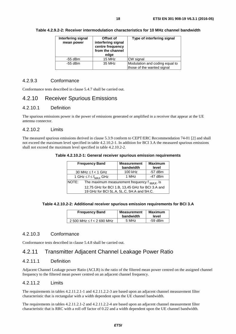
BER performance requirement at BER ≤ 10-6 (or equivalent PER) shall be met when the following signals are coupled to UE antenna input:
- A wanted signal at the assigned channel frequency, with mean power 6 dB above PSENS10.
- Two interfering signals with the following parameters.
ETSI
ETSI EN 301 908-19 V6.3.1 (2016-05)18
Table 4.2.9.2-2: Receiver intermodulation characteristics for 10 MHz channel bandwidth
Interfering signal mean power
Offset of interfering signal centre frequency from the channel
edge
Type of interfering signal
-55 dBm 15 MHz CW signal -55 dBm 35 MHz Modulation and coding equal to
those of the wanted signal
4.2.9.3 Conformance
Conformance tests described in clause 5.4.7 shall be carried out.
4.2.10 Receiver Spurious Emissions
4.2.10.1 Definition
The spurious emissions power is the power of emissions generated or amplified in a receiver that appear at the UE antenna connector.
4.2.10.2 Limits
The measured spurious emissions derived in clause 5.3.9 conform to CEPT/ERC Recommendation 74-01 [2] and shall not exceed the maximum level specified in table 4.2.10.2-1. In addition for BCI 3.A the measured spurious emissions shall not exceed the maximum level specified in table 4.2.10.2-2.
Table 4.2.10.2-1: General receiver spurious emission requirements
12,75 GHz for BCI 1.B, 13,45 GHz for BCI 3.A and 19 GHz for BCI 5L.A, 5L.C, 5H.A and 5H.C.
Table 4.2.10.2-2: Additional receiver spurious emission requirements for BCI 3.A
Frequency Band Measurement bandwidth
Maximum level
2 500 MHz ≤ f < 2 690 MHz 5 MHz -59 dBm
4.2.10.3 Conformance
Conformance tests described in clause 5.4.8 shall be carried out.
4.2.11 Transmitter Adjacent Channel Leakage Power Ratio
4.2.11.1 Definition
Adjacent Channel Leakage power Ratio (ACLR) is the ratio of the filtered mean power centred on the assigned channel frequency to the filtered mean power centred on an adjacent channel frequency.
4.2.11.2 Limits
The requirements in tables 4.2.11.2.1-1 and 4.2.11.2.2-3 are based upon an adjacent channel measurement filter characteristic that is rectangular with a width dependent upon the UE channel bandwidth.
The requirements in tables 4.2.11.2.1-2 and 4.2.11.2.2-4 are based upon an adjacent channel measurement filter characteristic that is RRC with a roll off factor of 0.22 and a width dependent upon the UE channel bandwidth.
ETSI
ETSI EN 301 908-19 V6.3.1 (2016-05)19
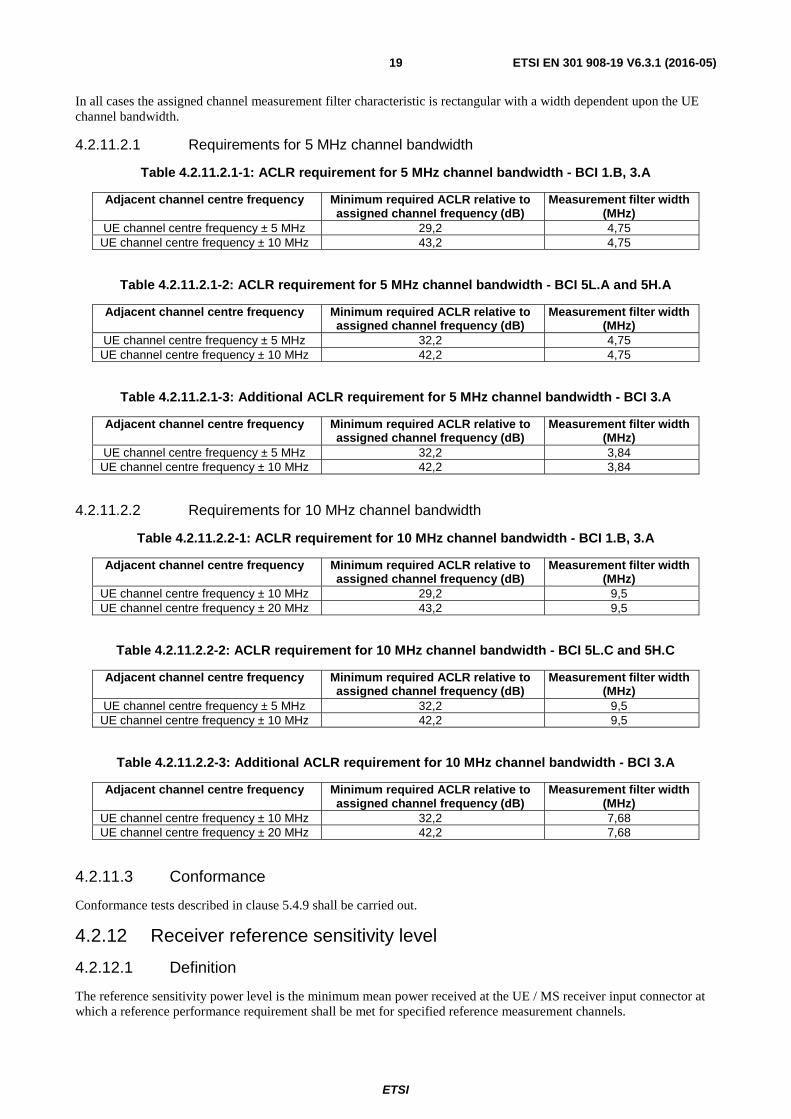
In all cases the assigned channel measurement filter characteristic is rectangular with a width dependent upon the UE channel bandwidth.
4.2.11.2.1 Requirements for 5 MHz channel bandwidth
Adjacent channel centre frequency Minimum required ACLR relative to assigned channel frequency (dB)
Measurement filter width (MHz)
UE channel centre frequency ± 10 MHz 32,2 7,68 UE channel centre frequency ± 20 MHz 42,2 7,68
4.2.11.3 Conformance
Conformance tests described in clause 5.4.9 shall be carried out.
4.2.12 Receiver reference sensitivity level
4.2.12.1 Definition
The reference sensitivity power level is the minimum mean power received at the UE / MS receiver input connector at which a reference performance requirement shall be met for specified reference measurement channels.
ETSI
ETSI EN 301 908-19 V6.3.1 (2016-05)20
4.2.12.2 Limits
The reference sensitivity level is the minimum mean power received at the UE / MS receiver input connector at which the Packet Error Rate (PER) shall not exceed a specific value.
The reference sensitivity level requirement tests are defined within WiMAX Forum® document WMF-T25-002-R010v06 [1].
The limits are detailed in the items below in the document:
• Clause 9.1.10: MS receiver sensitivity
• Appendix 1 (This section provides generic test packets, receiver sensitivity requirements, Bit Error Rate (BER) to Packet Error Rate (PER) conversion and Qualitative tests versus Functional tests methodology.)
• Appendix 3 (A 3.1 Measuring PER for MS. A 3.2 Measuring PER for BS.)
4.2.12.3 Conformance
Conformance tests described in clause 5.4.10 shall be carried out.
5 Testing for compliance with technical requirements
5.1 Environmental conditions for testing The technical requirements of the present document apply under the environmental profile, for intended operation of the equipment and antennas, declared by the manufacturer.
The environmental profile may be determined by the environmental class of the equipment according to the guidance given in ETSI EN 300 019-1-0 [i.5].
The combination of the equipment and its antennas shall comply with all the requirements of the present document at all times when operating within the boundary limits of the declared operational environmental profile.
5.2 Product information The following information shall be stated by the manufacturer in order to carry out the test suites:
• the operating RF channel centre frequency range of the equipment;
• the BCI;
• the nominal occupied channel bandwidth(s);
• the modulation format(s) employed by the equipment;
• the nominal maximum output power (Pnom) from the equipment and power class;
• the operational environmental profile(s) applicable to the equipment;
• the receiver sensitivity levels PSENS5 and PSENS10 and the equipment receiver thermal noise power Nth
(in dBm).
5.3 Interpretation of the measurement results The interpretation of the results recorded in a test report for the measurements described in the present document shall be as follows:
• the measured value related to the corresponding limit shall be used to decide whether the user equipment meets the requirements of the present document;
ETSI
ETSI EN 301 908-19 V6.3.1 (2016-05)21
• the value of the measurement uncertainty for the measurement of each parameter shall be documented in the test report;
• the recorded value of the measurement uncertainty shall be, for each measurement, equal to or lower than the figures in table 5.3-1.
For the test methods, according to the present document, the measurement uncertainty figures shall be calculated and shall correspond to an expansion factor (coverage factor) k = 1,96 (which provides a confidence level of 95 % in the case where the distributions characterizing the actual measurement uncertainties are normal (Gaussian)). Principles for the calculation of measurement uncertainty are contained in ETSI TR 100 028 [i.6] or ETSI TR 102 215 [i.4].
Table 5.3-1 is based on such expansion factors.
Table 5.3-1: Maximum measurement uncertainty of the test system
Parameter Conditions Uncertainty Maximum output power tolerance ±0,7 dB Spectrum emission mask ±1,5 dB Transmitter Spurious Emissions 9 kHz < f ≤ 4 GHz:
4 GHz < f ≤ 12,75 GHz: ±2,0 dB ±4,0 dB
Transmitter Minimum Output Power ±1,0 dB Receiver Adjacent Channel Selectivity (ACS) ±1,1 dB Receiver Blocking Characteristics ±1,3 dB Receiver Spurious Response ±1,3 dB Receiver Intermodulation Characteristics ±1,4 dB Receiver spurious emissions 30 MHz ≤ f ≤ 4,0 GHz:
4 GHz < f ≤ 12,75 GHz: ±2,0 dB ±4,0 dB
Transmitter adjacent channel leakage power ratio ±0,8 dB NOTE 1: For RF tests it should be noted that the uncertainties in table 5.3-1 apply to the test system
operating into a nominal 50 Ω load and do not include system effects due to mismatch between the EUT and the test system.
NOTE 2: If the test system for a test is known to have a measurement uncertainty greater than that specified in table 5.3-1, this equipment can still be used provided that an adjustment is made follows: any additional uncertainty in the test system over and above that specified in table 5.3-1 should be used to tighten the test requirements - making the test harder to pass (for some tests, e.g. receiver tests, this may require modification of stimulus signals). This procedure will ensure that a test system not compliant with table 5.3-1 does not increase the probability of passing an EUT that would otherwise have failed a test if a test system compliant with table 5.3-1 had been used.
5.4 Essential radio test suites All tests are carried out under normal environmental conditions unless otherwise specified.
5.4.1 Transmitter Maximum and Minimum Output Power
The purpose of this test is to verify compliance of UE equipment transmitter maximum output power and minimum transmit power control in support of the requirements of clauses 4.2.2 and 4.2.5.
5.4.1.1 Method of measurement
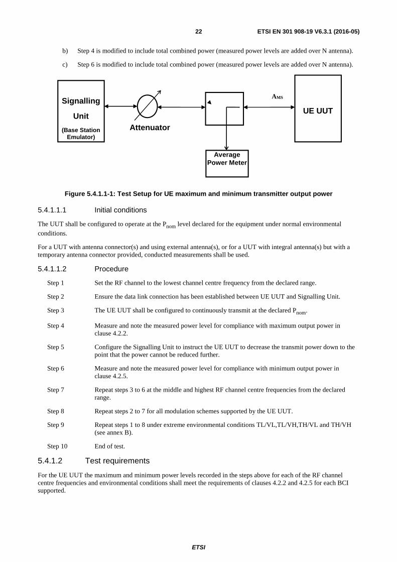
Figure 5.4.1.1-1 shows the test setup for testing UE nominal maximum and minimum output transmitter power.
In the case that UE supports multiple transmit antenna (antenna 1 to N):
1) If single transmit antenna is a valid mode of operation, steps 1 to 9 below shall be performed on a selected single antenna port.
2) To test the mode with multiple antenna enabled:
a) Steps 1 to 9 below shall be repeated when all antenna are enabled (e.g. each antenna is transmitting at Pnom - 10log10(N) level).
ETSI
ETSI EN 301 908-19 V6.3.1 (2016-05)22
b) Step 4 is modified to include total combined power (measured power levels are added over N antenna).
c) Step 6 is modified to include total combined power (measured power levels are added over N antenna).
Figure 5.4.1.1-1: Test Setup for UE maximum and minimum transmitter output power
5.4.1.1.1 Initial conditions
The UUT shall be configured to operate at the Pnom level declared for the equipment under normal environmental
conditions.
For a UUT with antenna connector(s) and using external antenna(s), or for a UUT with integral antenna(s) but with a temporary antenna connector provided, conducted measurements shall be used.
5.4.1.1.2 Procedure
Step 1 Set the RF channel to the lowest channel centre frequency from the declared range.
Step 2 Ensure the data link connection has been established between UE UUT and Signalling Unit.
Step 3 The UE UUT shall be configured to continuously transmit at the declared Pnom.
Step 4 Measure and note the measured power level for compliance with maximum output power in clause 4.2.2.
Step 5 Configure the Signalling Unit to instruct the UE UUT to decrease the transmit power down to the point that the power cannot be reduced further.
Step 6 Measure and note the measured power level for compliance with minimum output power in clause 4.2.5.
Step 7 Repeat steps 3 to 6 at the middle and highest RF channel centre frequencies from the declared range.
Step 8 Repeat steps 2 to 7 for all modulation schemes supported by the UE UUT.
Step 9 Repeat steps 1 to 8 under extreme environmental conditions TL/VL,TL/VH,TH/VL and TH/VH (see annex B).
Step 10 End of test.
5.4.1.2 Test requirements
For the UE UUT the maximum and minimum power levels recorded in the steps above for each of the RF channel centre frequencies and environmental conditions shall meet the requirements of clauses 4.2.2 and 4.2.5 for each BCI supported.
UE UUT
Signalling
Unit
(Base Station Emulator)
AMS
Attenuator
Average Power Meter
ETSI
ETSI EN 301 908-19 V6.3.1 (2016-05)23
5.4.2 Transmitter Spectrum Emission Mask
The purpose of this test is to verify compliance of UE equipment to the transmitter spectrum emission mask requirements of clause 4.2.3.
5.4.2.1 Method of measurement
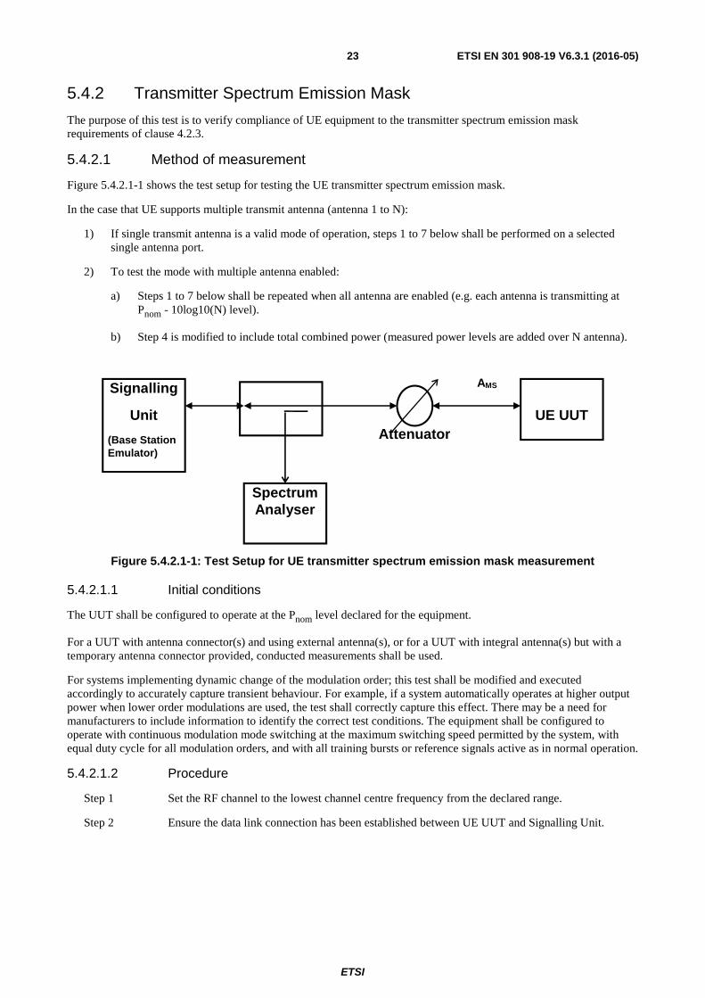
Figure 5.4.2.1-1 shows the test setup for testing the UE transmitter spectrum emission mask.
In the case that UE supports multiple transmit antenna (antenna 1 to N):
1) If single transmit antenna is a valid mode of operation, steps 1 to 7 below shall be performed on a selected single antenna port.
2) To test the mode with multiple antenna enabled:
a) Steps 1 to 7 below shall be repeated when all antenna are enabled (e.g. each antenna is transmitting at Pnom - 10log10(N) level).
b) Step 4 is modified to include total combined power (measured power levels are added over N antenna).
Figure 5.4.2.1-1: Test Setup for UE transmitter spectrum emission mask measurement
5.4.2.1.1 Initial conditions
The UUT shall be configured to operate at the Pnom level declared for the equipment.
For a UUT with antenna connector(s) and using external antenna(s), or for a UUT with integral antenna(s) but with a temporary antenna connector provided, conducted measurements shall be used.
For systems implementing dynamic change of the modulation order; this test shall be modified and executed accordingly to accurately capture transient behaviour. For example, if a system automatically operates at higher output power when lower order modulations are used, the test shall correctly capture this effect. There may be a need for manufacturers to include information to identify the correct test conditions. The equipment shall be configured to operate with continuous modulation mode switching at the maximum switching speed permitted by the system, with equal duty cycle for all modulation orders, and with all training bursts or reference signals active as in normal operation.
5.4.2.1.2 Procedure
Step 1 Set the RF channel to the lowest channel centre frequency from the declared range.
Step 2 Ensure the data link connection has been established between UE UUT and Signalling Unit.
Signalling
Unit
(Base Station Emulator)
Spectrum Analyser
UE UUT
AMS
Attenuator
ETSI
ETSI EN 301 908-19 V6.3.1 (2016-05)24
Step 3 The spectrum analyser shall be correctly configured to measure the spectral mask. To avoid having the spectrum analyser average the spectrum during periods when there is no transmission occurring, it is important to use a gated trigger mode. The gated trigger should be set up so that the spectrum analyser is only triggered when the UUT is transmitting. Some spectrum analysers can be configured for a gated trigger using the RF burst directly. However, other spectrum analysers will require an independent gate signal, and this signal shall be derived from the Signalling Unit. It is therefore recommended that the Signalling Unit provides a frame trigger signal.
Measurements should only be conducted during the transmission period.
Step 4 Measure and note the signal spectrum over the range specified in clause 4.2.3.2 in accordance with the specified measurement bandwidths in the tables. Note that measurement aggregation is needed to compare with specified numbers according to the 1 MHz measurement bandwidth in the tables.
Step 5 Repeat steps 3 and 4 at the middle and highest RF channel centre frequencies from the declared range.
Step 6 Repeat steps 2 to 5 for all modulation schemes supported by the equipment under test.
Step 7 End of test.
5.4.2.2 Test requirements
For the UE UUT the signal spectrum recorded in the steps above for each of the RF channel centre frequencies shall meet the requirements of clause 4.2.3 for the appropriate channel bandwidths and BCI supported.
5.4.3 Transmitter spurious emissions
The purpose of this test is to verify compliance of UE equipment to the transmitter spurious emission requirements of clause 4.2.4.
5.4.3.1 Method of measurement
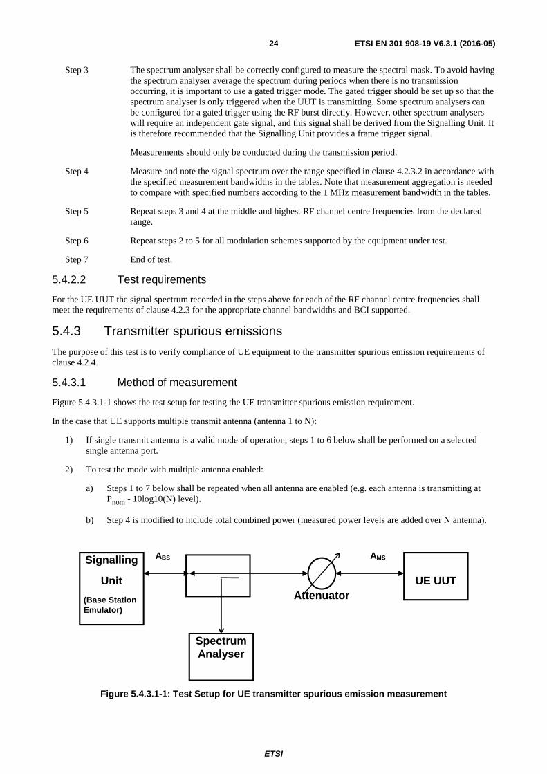
Figure 5.4.3.1-1 shows the test setup for testing the UE transmitter spurious emission requirement.
In the case that UE supports multiple transmit antenna (antenna 1 to N):
1) If single transmit antenna is a valid mode of operation, steps 1 to 6 below shall be performed on a selected single antenna port.
2) To test the mode with multiple antenna enabled:
a) Steps 1 to 7 below shall be repeated when all antenna are enabled (e.g. each antenna is transmitting at Pnom - 10log10(N) level).
b) Step 4 is modified to include total combined power (measured power levels are added over N antenna).
Figure 5.4.3.1-1: Test Setup for UE transmitter spurious emission measurement
Signalling
Unit
(Base Station Emulator)
Spectrum Analyser
UE UUT
AMS
Attenuator
ABS
ETSI
ETSI EN 301 908-19 V6.3.1 (2016-05)25
5.4.3.1.1 Initial conditions
The UUT shall be configured to operate at the Pnom level declared for the equipment.
For a UUT with antenna connector(s) and using external antenna(s), or for a UUT with integral antenna(s) but with a temporary antenna connector provided, conducted measurements shall be used.
In the spectrum analyser, set the measurement bandwidth as specified in the relevant table of clause 4.2.4. Set the video bandwidth to a value of three times the measurement bandwidth. True RMS detector shall be used.
For systems implementing dynamic change of the modulation order, the equipment shall be configured to operate with continuous modulation mode switching at the maximum switching speed permitted by the system, with equal duty cycle for all modulation orders, and with all training bursts or reference signals active as in normal operation.
5.4.3.1.2 Procedure
Step 1 Set the RF channel at lowest channel centre frequency from the declared range.
Step 2 Ensure the data link connection has been established between UE UUT and Signalling Unit.
Step 3 The UE UUT is configured to transmit at its Pnom output power.
Step 4 Measure and note the UE transmitter spurious emissions over the frequency range and within the specified measurement bandwidth specified in the relevant table of clause 4.2.4.
Step 5 Repeat steps 2 to 4 at the middle and highest RF channel centre frequencies from the declared range for each BCI supported.
Step 6 End of test.
5.4.3.2 Test requirements
For the UE UUT the transmitter spurious emission levels recorded in the steps above for each of the RF channel centre frequencies shall meet the requirements of clause 4.2.4.
5.4.4 Receiver Adjacent Channel Selectivity (ACS)
The purpose of this test is to verify compliance of UE equipment to the receiver adjacent channel selectivity requirements of clause 4.2.6.
5.4.4.1 Method of measurement
The interfering source shall be a conforming unsynchronized signal with the same signalling technology as the in-channel signal.
In the case that the UE supports multiple receive antennas (antenna 1 to N), a single channel is connected to the multiple antenna ports through a splitter. In this case, the test system is calibrated to the antenna ports to take into account splitter losses and identical signals and power levels (±0,3 dB) are applied to each antenna port.
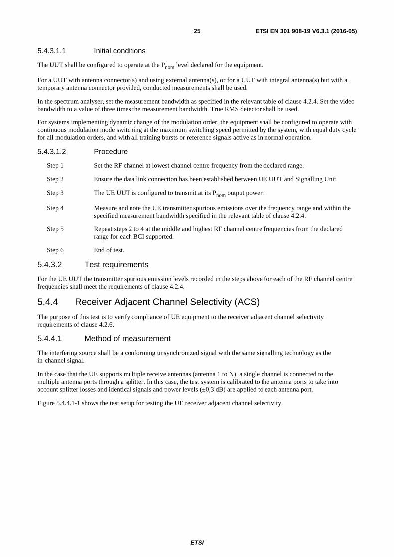
Figure 5.4.4.1-1 shows the test setup for testing the UE receiver adjacent channel selectivity.
ETSI
ETSI EN 301 908-19 V6.3.1 (2016-05)26
Figure 5.4.4.1-1: Test Setup for UE receiver adjacent channel selectivity measurement
5.4.4.1.1 Initial conditions
Set the interfering source to the first adjacent channel operating frequency in accordance with table 4.2.6.2-1. Set the interfering signal source bandwidth to be the same as the in-channel operating bandwidth. Turn the interfering source off.
5.4.4.1.2 Procedure
Step 1 Set the UUT and signalling unit to the RF channel corresponding to the lowest channel centre frequency from the declared range.
Step 2 Adjust the received signal level at AUUT to be 3dB above the sensitivity level PSENS. Note the
signal level is measured over the time period of the data burst only within the downlink transmission.
Step 3 Turn on the interfering source.
Step 4 Increase the interfering source power to the appropriate adjacent channel power level identified in table 4.2.6.2-1.
Step 5 Perform a BER measurement and record the results.
Step 6 Turn the interference source off.
Step 7 Set the interfering source to the second adjacent channel operating frequency. Repeat steps 2 to 6 above for the second adjacent channel test cases and record the results.
Step 8 Reset the interfering source to the first adjacent channel operating frequency and repeat steps 2 to 7 at the middle and highest RF channel centre frequencies from the declared range.
Step 9 End of test.
5.4.4.2 Test requirements
For the UE UUT the worst case BER measurement recorded in steps above for each of the RF channel centre frequencies shall meet the requirements of clause 4.2.6 for each BCI supported.
5.4.5 Receiver Blocking Characteristics
The purpose of this test is to verify compliance of UE equipment to the receiver blocking characteristic requirements of clause 4.2.7.
ETSI
ETSI EN 301 908-19 V6.3.1 (2016-05)27
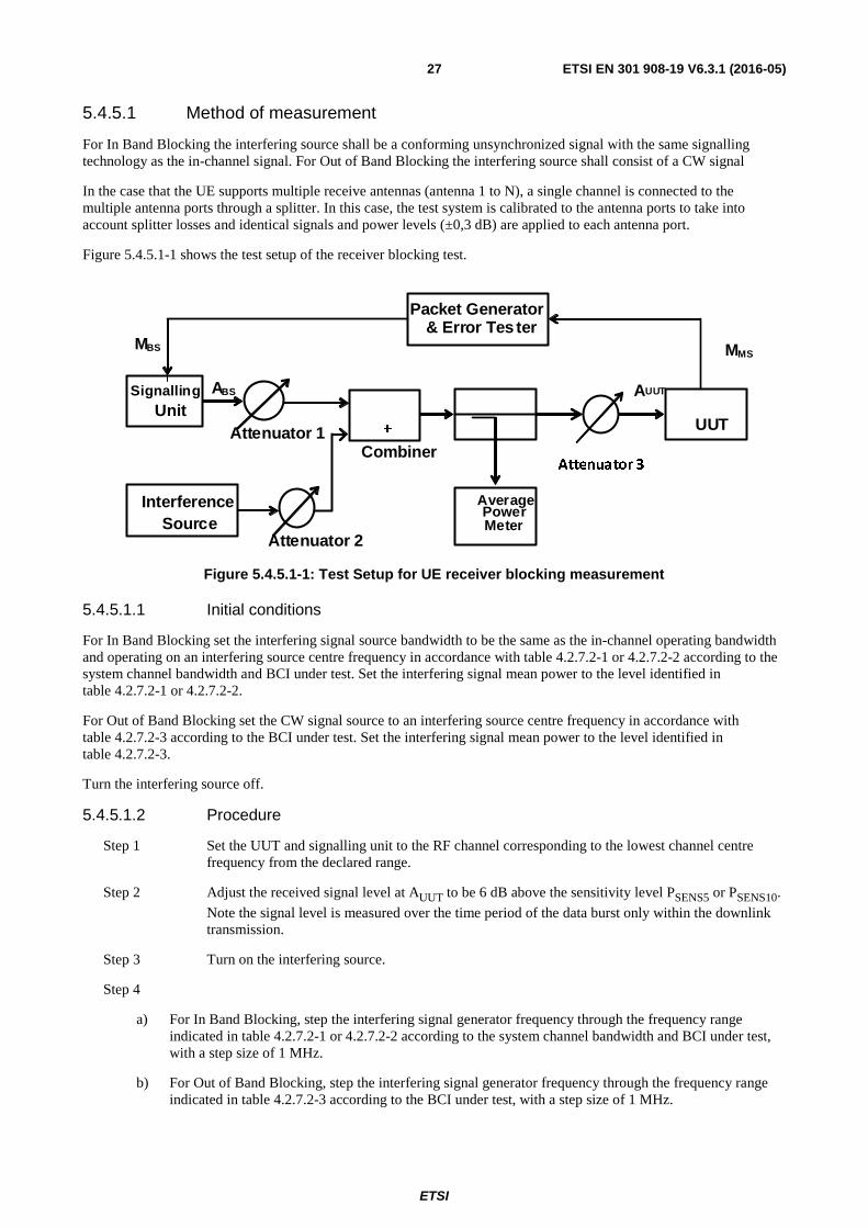
5.4.5.1 Method of measurement
For In Band Blocking the interfering source shall be a conforming unsynchronized signal with the same signalling technology as the in-channel signal. For Out of Band Blocking the interfering source shall consist of a CW signal
In the case that the UE supports multiple receive antennas (antenna 1 to N), a single channel is connected to the multiple antenna ports through a splitter. In this case, the test system is calibrated to the antenna ports to take into account splitter losses and identical signals and power levels (±0,3 dB) are applied to each antenna port.
Figure 5.4.5.1-1 shows the test setup of the receiver blocking test.
MMS
Attenuator 2
Signalling Unit
Packet Generator & Error Tes ter
Average Power
Meter
MBS
UUT
ABS
Attenuator 1
AUUT
+
Interference Source
Combiner Attenuator 3
Figure 5.4.5.1-1: Test Setup for UE receiver blocking measurement
5.4.5.1.1 Initial conditions
For In Band Blocking set the interfering signal source bandwidth to be the same as the in-channel operating bandwidth and operating on an interfering source centre frequency in accordance with table 4.2.7.2-1 or 4.2.7.2-2 according to the system channel bandwidth and BCI under test. Set the interfering signal mean power to the level identified in table 4.2.7.2-1 or 4.2.7.2-2.
For Out of Band Blocking set the CW signal source to an interfering source centre frequency in accordance with table 4.2.7.2-3 according to the BCI under test. Set the interfering signal mean power to the level identified in table 4.2.7.2-3.
Turn the interfering source off.
5.4.5.1.2 Procedure
Step 1 Set the UUT and signalling unit to the RF channel corresponding to the lowest channel centre frequency from the declared range.
Step 2 Adjust the received signal level at AUUT to be 6 dB above the sensitivity level PSENS5 or PSENS10.
Note the signal level is measured over the time period of the data burst only within the downlink transmission.
Step 3 Turn on the interfering source.
Step 4
a) For In Band Blocking, step the interfering signal generator frequency through the frequency range indicated in table 4.2.7.2-1 or 4.2.7.2-2 according to the system channel bandwidth and BCI under test, with a step size of 1 MHz.
b) For Out of Band Blocking, step the interfering signal generator frequency through the frequency range indicated in table 4.2.7.2-3 according to the BCI under test, with a step size of 1 MHz.
ETSI
ETSI EN 301 908-19 V6.3.1 (2016-05)28
Step 5 Measure the BER of the desired signal received for each step of the interfering frequency and record the results.
Step 6 Record any interfering signal centre frequency at which the blocking requirement is not met.
Step 7 Turn the interference source off.
Step 8 Repeat the test procedure at middle and highest channel centre frequencies for the desired received signal from the declared range.
Step 9 End of test.
5.4.5.2 Test requirements
For the UE UUT the worst case BER measurement recorded in the steps above for each step of the interfering signal and at each of the RF channel centre frequencies shall meet the requirements of clause 4.2.7 for each BCI supported.
5.4.6 Receiver Spurious Response
The purpose of this test is to verify compliance of UE equipment to the receiver spurious response requirements of clause 4.2.8.
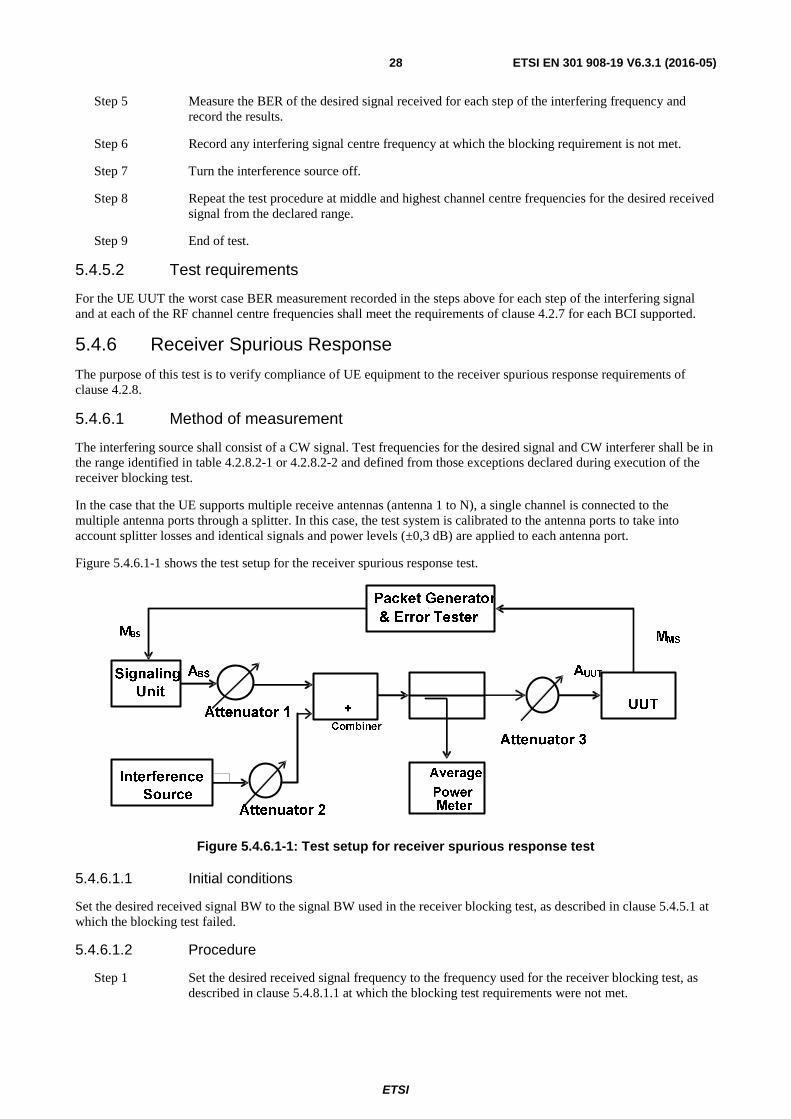
5.4.6.1 Method of measurement
The interfering source shall consist of a CW signal. Test frequencies for the desired signal and CW interferer shall be in the range identified in table 4.2.8.2-1 or 4.2.8.2-2 and defined from those exceptions declared during execution of the receiver blocking test.
In the case that the UE supports multiple receive antennas (antenna 1 to N), a single channel is connected to the multiple antenna ports through a splitter. In this case, the test system is calibrated to the antenna ports to take into account splitter losses and identical signals and power levels (±0,3 dB) are applied to each antenna port.
Figure 5.4.6.1-1 shows the test setup for the receiver spurious response test.
Figure 5.4.6.1-1: Test setup for receiver spurious response test
5.4.6.1.1 Initial conditions
Set the desired received signal BW to the signal BW used in the receiver blocking test, as described in clause 5.4.5.1 at which the blocking test failed.
5.4.6.1.2 Procedure
Step 1 Set the desired received signal frequency to the frequency used for the receiver blocking test, as described in clause 5.4.8.1.1 at which the blocking test requirements were not met.
ETSI
ETSI EN 301 908-19 V6.3.1 (2016-05)29
Step 2 Adjust the received signal level at AUUT to be 6 dB above the sensitivity level PSENS5 or PSENS10
according to the channel bandwidth under test. Note the signal level is measured over the time period of the data burst only within the downlink transmission.
Step 3 Set the frequency of the interferer signal according the recorded spurious response frequency values obtained from the blocking test as described in clause 5.4.5.1.2 step 6 at which the blocking test requirements were not met.
Step 4 Set the power level of the interferer according to either table 4.2.8.2-1 or 4.2.8.2-2 as appropriate.
Step 5 Measure the BER of the desired signal received for each frequency of the interferer signal and record the results.
Step 6 Repeat the test procedure at all frequencies which the blocking test requirements were not met.
Step 7 End of test.
5.4.6.2 Test requirements
For the UE UUT the worst case BER measurement recorded in the steps above for each of the interfering signals shall meet the requirements of clause 4.2.8.
5.4.7 Receiver Intermodulation characteristics
The purpose of this test is to verify compliance of UE equipment to the receiver intermodulation characteristic requirements of clause 4.2.9.
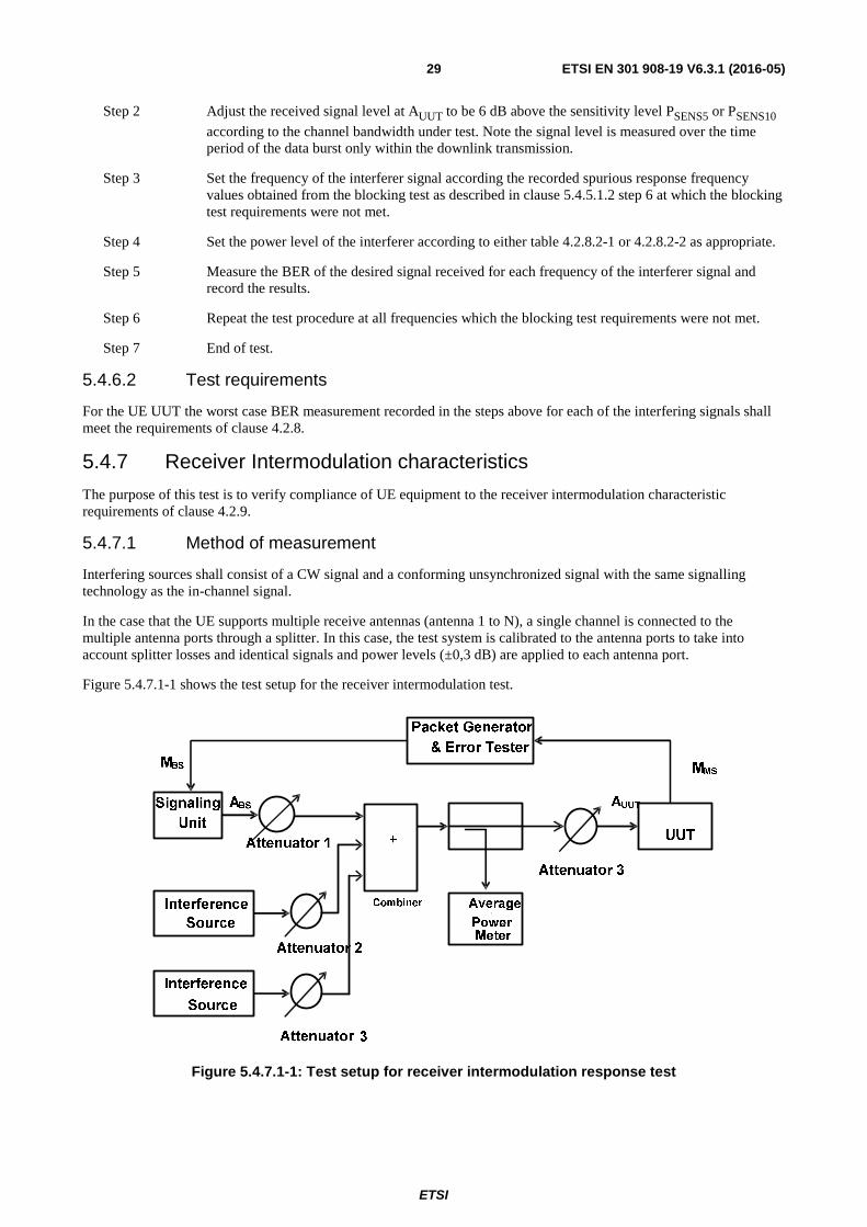
5.4.7.1 Method of measurement
Interfering sources shall consist of a CW signal and a conforming unsynchronized signal with the same signalling technology as the in-channel signal.
In the case that the UE supports multiple receive antennas (antenna 1 to N), a single channel is connected to the multiple antenna ports through a splitter. In this case, the test system is calibrated to the antenna ports to take into account splitter losses and identical signals and power levels (±0,3 dB) are applied to each antenna port.
Figure 5.4.7.1-1 shows the test setup for the receiver intermodulation test.
Figure 5.4.7.1-1: Test setup for receiver intermodulation response test
ETSI
ETSI EN 301 908-19 V6.3.1 (2016-05)30
5.4.7.1.1 Initial conditions
Set the modulated interfering signal source bandwidth to be the same as the in-channel operating bandwidth. Set the interfering source centre frequency to have a positive frequency offset from the upper wanted channel edge in accordance with table 4.2.9.2-1 or 4.2.9.2-2 according to the system channel bandwidth under test. Set the modulated interfering signal mean power to the level identified in table 4.2.9.2-1 or 4.2.9.2-2 according to the system channel bandwidth under test.
Set the CW interfering signal frequency to have a positive frequency offset from the upper wanted channel edge in accordance with table 4.2.9.2-1 or 4.2.9.2-2 according to the system channel bandwidth under test. Set the CW interfering signal mean power to the level identified in table 4.2.9.2-1 or 4.2.9.2-2 according to the system channel bandwidth under test. Turn the interfering sources off.
5.4.7.1.2 Procedure
Step 1 Set the UUT and signalling unit to the RF channel corresponding to the lowest channel centre frequency from the declared range.
Step 2 Adjust the received signal level at AUUT to be 6 dB above the sensitivity level PSENS + 6 dB. Note
the signal level is measured over the time period of the data burst only within the downlink transmission.
Step 3 Turn on the interfering sources.
Step 4 Measure the BER of the desired signal received and record the results.
Step 5 Turn the interfering sources off.
Step 6 Reconfigure the interfering sources to transmit with negative frequency offsets from the lower wanted channel edge as defined in table 4.2.9.2-1 or 4.2.9.2-2 according to the system channel bandwidth under test.
Step 7 Turn on the interfering sources.
Step 8 Measure the BER of the desired signal received and record the results.
Step 9 Turn the interfering sources off.
Step 10 Repeat the test procedure at middle and highest channel centre frequencies for the desired received signal from the declared range.
Step 11 End of test.
5.4.7.2 Test requirements
For the UE UUT the worst case BER measurement recorded in the steps above for each of the RF channel centre frequencies shall meet the requirements of clause 4.2.9 for each BCI supported.
5.4.8 Receiver Spurious Emissions
The purpose of this test is to verify compliance of UE equipment to the receiver spurious emission requirements of clause 4.2.10.
ETSI
ETSI EN 301 908-19 V6.3.1 (2016-05)31
5.4.8.1 Method of measurement
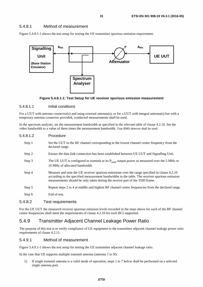
Figure 5.4.8.1-1 shows the test setup for testing the UE transmitter spurious emission requirement.
Figure 5.4.8.1-1: Test Setup for UE receiver spurious emission measurement
5.4.8.1.1 Initial conditions
For a UUT with antenna connector(s) and using external antenna(s), or for a UUT with integral antenna(s) but with a temporary antenna connector provided, conducted measurements shall be used.
In the spectrum analyser, set the measurement bandwidth as specified in the relevant table of clause 4.2.10. Set the video bandwidth to a value of three times the measurement bandwidth. True RMS detector shall be used.
5.4.8.1.2 Procedure
Step 1 Set the UUT to the RF channel corresponding to the lowest channel centre frequency from the declared range.
Step 2 Ensure the data link connection has been established between UE UUT and Signalling Unit.
Step 3 The UE UUT is configured to transmit at its Pnom output power as measured over the 5 MHz or
10 MHz of allocated bandwidth.
Step 4 Measure and note the UE receiver spurious emissions over the range specified in clause 4.2.10 according to the specified measurement bandwidths in the table. The receiver spurious emission measurements should be only taken during the receive part of the TDD frame.
Step 5 Repeat steps 2 to 4 at middle and highest RF channel centre frequencies from the declared range.
Step 6 End of test.
5.4.8.2 Test requirements
For the UE UUT the measured receiver spurious emission levels recorded in the steps above for each of the RF channel centre frequencies shall meet the requirements of clause 4.2.10 for each BCI supported.
5.4.9 Transmitter Adjacent Channel Leakage Power Ratio
The purpose of this test is to verify compliance of UE equipment to the transmitter adjacent channel leakage power ratio requirements of clause 4.2.11.
5.4.9.1 Method of measurement
Figure 5.4.9.1-1 shows the test setup for testing the UE transmitter adjacent channel leakage ratio.
In the case that UE supports multiple transmit antenna (antenna 1 to N):
1) If single transmit antenna is a valid mode of operation, steps 1 to 7 below shall be performed on a selected single antenna port.
Signalling
Unit
(Base Station Emulator)
Spectrum Analyser
UE UUT
AMS
Attenuator
ABS
ETSI
ETSI EN 301 908-19 V6.3.1 (2016-05)32
2) To test the mode with multiple antenna enabled:
a) Steps 1 to 7 below shall be repeated when all antenna are enabled (e.g. each antenna is transmitting at Pnom - 10log10(N) level).
b) Step 4 is modified to include total combined power (measured power levels are added over N antenna).
Figure 5.4.9.1-1: Test Setup for UE transmitter adjacent channel leakage ratio measurement
5.4.9.1.1 Initial conditions
The UUT shall be configured to operate at the Pnom level declared for the equipment under normal environmental
conditions.
For a UUT with antenna connector(s) and using external antenna(s), or for a UUT with integral antenna(s) but with a temporary antenna connector provided, conducted measurements shall be used.
For systems implementing dynamic change of the modulation order; this test shall be modified and executed accordingly to accurately capture transient behaviour. For example, if a system automatically operates at higher output power when lower order modulations are used, the test shall correctly capture this effect. There may be a need for manufacturers to include information to identify the correct test conditions. The equipment shall be configured to operate with continuous modulation mode switching at the maximum switching speed permitted by the system, with equal duty cycle for all modulation orders, and with all training bursts or reference signals active as in normal operation.
5.4.9.1.2 Procedure
Step 1 Set the RF channel to the lowest channel centre frequency from the declared range.
Step 2 Ensure the data link connection has been established between UE UUT and Signalling Unit.
Step 3 The spectrum analyser shall be correctly configured to measure the aggregated power. To avoid having the spectrum analyser average the spectrum during periods when there is no transmission occurring (such as a DL burst), it is important to use a gated trigger mode. The gated trigger should be set up so that the spectrum analyser is only triggered when the UUT is transmitting. Some spectrum analysers can be configured for a gated trigger using the RF burst directly. However, other spectrum analysers will require an independent gate signal, and this signal shall be derived from the Base Station Emulator (BSE). It is therefore recommended that the BSE provide a frame trigger signal.
Measurements should only be conducted during the transmission.
Step 4 Measure the aggregated power measured over a frequency range equal to 4,75 MHz and 9,5 MHz (for 5 MHz and 10 MHz cases respectively) centred on the assigned channel frequency.
Step 5 Average over a sufficient number of transmitted bursts to obtain a stable reading.
Signaling
Unit
(Base Station Emulator)
Spectrum Analyser
UE UUT
AMS
Attenuator
ETSI
ETSI EN 301 908-19 V6.3.1 (2016-05)33
Step 6 Measure the aggregated power measured over a frequency range equal to 4,75 MHz and 9,5 MHz (for 5 MHz and 10 MHz cases respectively) centred on the first lower adjacent channel frequency which is 5 MHz (10 MHz for 10 MHz channel bandwidth) apart from operating RF channel centre frequency.
Step 7 Average over a sufficient number of transmitted bursts to obtain a stable reading.
Step 8 Calculate the ACLR by: (Power according to step 5)/(Power according to step 7).
Step 9 Repeat steps 4 to 8 for the second adjacent (lower) RF channel (centre frequency 10 MHz for the 5 MHz channel bandwidth and 20 MHz for 10 MHz channel bandwidth, respectively, below the assigned channel frequency of the transmitted signal) and also for the first and second upper adjacent RF channel.
Step 10 Run steps 2 to 9 at the middle and highest RF channel centre frequencies from the declared range.
Step 11 Repeat steps 1 to 10 under extreme environmental conditions TL/VL,TL/VH,TH/VL and TH/VH (see annex B).
Step 12 End of test.
5.4.9.2 Test requirements
For the UE UUT the maximum power levels recorded in the steps above and the ACLR calculation for each of the RF channel centre frequencies and environmental conditions shall meet the requirements of clause 4.2.11 for each BCI supported.
5.4.10 Receiver reference sensitivity level
5.4.10.1 Method of test
The test requirement is in WiMAX Forum® document WMF-T25-002-R010v06 [1].
All of the items below are found in this document:
• Clause 9.1.10: MS receiver sensitivity
• Appendix 1 (This section provides generic test packets, receiver sensitivity requirements, Bit Error Rate (BER) to Packet Error Rate (PER) conversion and Qualitative tests versus Functional tests methodology.)
• Appendix 3 (A 3.1 Measuring PER for MS. A 3.2 Measuring PER for BS.)
5.4.10.2 Test requirement
The results obtained shall meet the limits defined in [1] in order to show compliance.
ETSI
ETSI EN 301 908-19 V6.3.1 (2016-05)34
Annex A (normative): Relationship between the present document and the essential requirements of Directive 2014/53/EU The present document has been prepared under the Commission's standardisation request C(2015) 5376 final [i.8] to provide one voluntary means of conforming to the essential requirements of Directive 2014/53/EU on the harmonisation of the laws of the Member States relating to the making available on the market of radio equipment and repealing Directive 1999/5/EC [i.2].
Once the present document is cited in the Official Journal of the European Union under that Directive, compliance with the normative clauses of the present document given in table A-1 confers, within the limits of the scope of the present document, a presumption of conformity with the corresponding essential requirements of that Directive, and associated EFTA regulations.
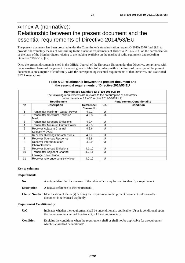
Table A-1: Relationship between the present document and the essential requirements of Directive 2014/53/EU
Harmonised Standard ETSI EN 301 908-19 The following requirements are relevant to the presumption of conformity
under the article 3.2 of Directive 2014/53/EU [i.2] Requirement Requirement Conditionality
No Description Reference: Clause No
U/C Condition
1 Transmitter Maximum Output Power 4.2.2 U 2 Transmitter Spectrum Emission
Mask 4.2.3 U
3 Transmitter Spurious Emissions 4.2.4 U 4 Transmitter Minimum Output Power 4.2.5 U 5 Receiver Adjacent Channel
Selectivity (ACS) 4.2.6 U
6 Receiver Blocking Characteristics 4.2.7 U 7 Receiver Spurious Response 4.2.8 U 8 Receiver Intermodulation
Characteristics 4.2.9 U
9 Receiver Spurious Emissions 4.2.10 U 10 Transmitter Adjacent Channel
Leakage Power Ratio 4.2.11 U
11 Receiver reference sensitivity level 4.2.12 U
Key to columns:
Requirement:
No A unique identifier for one row of the table which may be used to identify a requirement.
Description A textual reference to the requirement.
Clause Number Identification of clause(s) defining the requirement in the present document unless another document is referenced explicitly.
Requirement Conditionality:
U/C Indicates whether the requirement shall be unconditionally applicable (U) or is conditional upon the manufacturers claimed functionality of the equipment (C).
Condition Explains the conditions when the requirement shall or shall not be applicable for a requirement which is classified "conditional".
ETSI
ETSI EN 301 908-19 V6.3.1 (2016-05)35
Presumption of conformity stays valid only as long as a reference to the present document is maintained in the list published in the Official Journal of the European Union. Users of the present document should consult frequently the latest list published in the Official Journal of the European Union.
Other Union legislation may be applicable to the product(s) falling within the scope of the present document.
ETSI
ETSI EN 301 908-19 V6.3.1 (2016-05)36
Annex B (normative): Environmental profile The following environmental conditions may be declared by the manufacturer:
• barometric pressure: minimum and maximum;
• temperature: normal and minimum/maximum extremes;
• relative humidity: maximum;
• power supply: normal and lower/upper voltage extremes.
Where an extreme environment is required then the various combinations of extreme temperatures together with the extreme voltages are shown below:
• low extreme Temperature/Low extreme Voltage (TL/VL);
• low extreme Temperature/High extreme Voltage (TL/VH);
• high extreme Temperature/Low extreme Voltage (TH/VL);
• high extreme Temperature/High extreme Voltage (TH/VH).
ETSI
ETSI EN 301 908-19 V6.3.1 (2016-05)37
Annex C (informative): Void
ETSI
ETSI EN 301 908-19 V6.3.1 (2016-05)38
Annex D (informative): Bibliography
• Directive 2004/108/EC of the European Parliament and of the Council of 15 December 2004 on the approximation of the laws of the Member States relating to electromagnetic compatibility and repealing Directive 89/336/EEC (EMC Directive).
• Directive 2006/95/EC of the European Parliament and of the Council of 12 December 2006 on the harmonisation of the laws of Member States relating to electrical equipment designed for use within certain voltage limits (LV Directive).
• WMF-T23-005-R015v06: "WiMAX Forum® Air Interface specifications - WiMAX Forum® Mobile Radio Specification".
• Directive 98/48/EC of the European Parliament and of the Council of 20 July 1998 amending Directive 98/34/EC laying down a procedure for the provision of information in the field of technical standards and regulations.
ETSI
ETSI EN 301 908-19 V6.3.1 (2016-05)39
History
Document history
V5.2.1 September 2011 Publication
V6.2.1 June 2013 Publication
V6.2.6 January 2016 EN Approval Procedure AP 20160420: 2016-01-21 to 2016-04-20