320
ACS550 User’s Manual ACS550-01 Drives (0.75…160 kW) ACS550-U1 Drives (1…200 hp)
| Date post: | 24-Oct-2014 |
| Category: |
Documents |
| Upload: | groper-alexandru |
| View: | 60 times |
| Download: | 3 times |
ACS550
User’s ManualACS550-01 Drives (0.75…160 kW)ACS550-U1 Drives (1…200 hp)
List of related manualsGENERAL MANUALS
ACS550-01/U1 User's Manual (0.75…160 kW) / (1…200 hp)3AFE64804588 (3AUA0000001418) (English)• Safety• Installation• Start-up, control with I/O and ID Run• Control panels• Application macros• Parameters• Embedded fieldbus• Fieldbus adapter• Diagnostics• Maintenance• Technical dataFlange Mounting Instructions
OPTION MANUALS(delivered with optional equipment)
MFDT-01 FlashDrop User's Manual3AFE68591074 (English)OHDI-01 115/230 V Digital Input Module User's Manual3AUA0000003101 (English) OREL-01 Relay Output Extension Module User's Manual3AUA0000001935 (English) OTAC-01 User’s Manual Pulse Encoder Interface Module User’s Manual3AUA0000001938 (English)RCAN-01 CANopen Adapter User's Manual3AFE64504231 (English)RCCL-01 CC-Link Adapter Module User's Manual3AUA0000061340 (English)RCNA-01 ControlNet Adapter User's Manual3AFE64506005 (English)RDNA-01 DeviceNet Adapter User's Manual3AFE64504223 (English)RECA-01 EtherCAT Adapter Module User's Manual3AUA0000043520 (English)
Kit, IP21 / UL type 1 Frame size Code (English)FMK-A-R1 R1 100000982FMK-A-R2 R2 100000984FMK-A-R3 R3 100000986FMK-A-R4 R4 100000988AC8-FLNGMT-R5 1 R5 ACS800-
PNTG01U-ENAC8-FLNGMT-R6 1 R61. Not available for ACS550-01 series
Kit, IP54 / UL type 12 Frame size Code (English)FMK-B-R1 R1 100000990FMK-B-R2 R2 100000992FMK-B-R3 R3 100000994FMK-B-R4 R4 100000996
REPL-01 Ethernet POWERLINK Adapter Module User's Manual3AUA0000052289 (English)RETA-01 Ethernet Adapter Module User's Manual3AFE64539736 (English)RETA-02 Ethernet Adapter Module User's Manual3AFE68895383 (English)RLON-01 LONWORKS® Adapter Module User’s Manual3AFE64798693 (English)RPBA-01 PROFIBUS DP Adapter User's Manual3AFE64504215 (English)SREA-01 Ethernet Adapter User's Manual3AUA0000042896 (English)Typical contents• Safety• Installation• Programming/Start-up• Diagnostics• Technical data
MAINTENANCE MANUALS
Guide for Capacitor Reforming in ACS50, ACS55, ACS150, ACS310, ACS320, ACS350, ACS550 and ACH5503AFE68735190 (English)
CANopen is a registered trademark of CAN in Automation e.V.CC-Link is a trademark of CC-Link Partner Association.ControlNet™ is a trademark of ODVA™.DeviceNet™ is a trademark of ODVA™.DRIVECOM is a registered trademark of DRIVECOM User Group e.V.EtherCAT is a registered trademark of Beckhoff.EtherNet/IP™ is a trademark of ODVA™.LONWORKS® is a registered trademark of Echelon Corporation.Modbus and Modbus/TCP are registered trademarks of Schneider Automation Inc.PROFIBUS, PROFIBUS DP and PROFINET IO are registered trademarks of Profibus International.
ACS550-01/U1 Drives0.75…160 kW
1…200 hp
User’s Manual
3AFE64804588 (3AUA0000001418) Rev GEN
EFFECTIVE: 2009-07-07SUPERSEDES: 3AFE64804588 (3AUA0000001418) Rev F 2007-04-16
© 2009 ABB Oy. All Rights Reserved.

ACS550-01/U1 User’s Manual 5
Safety
Use of warnings and notesThere are two types of safety instructions throughout this manual:
• Notes draw attention to a particular condition or fact, or give information on a subject.
• Warnings caution you about conditions which can result in serious injury or death and/or damage to the equipment. They also tell you how to avoid the danger. The warning symbols are used as follows:
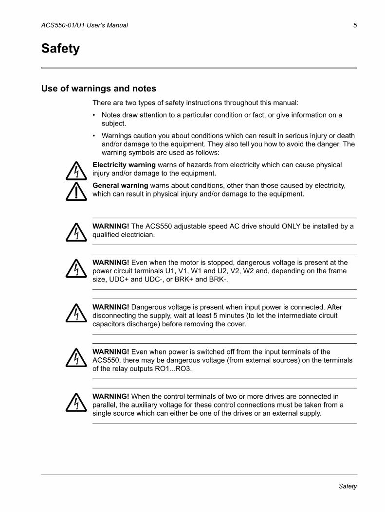
Electricity warning warns of hazards from electricity which can cause physical injury and/or damage to the equipment.
General warning warns about conditions, other than those caused by electricity, which can result in physical injury and/or damage to the equipment.
WARNING! The ACS550 adjustable speed AC drive should ONLY be installed by a qualified electrician.
WARNING! Even when the motor is stopped, dangerous voltage is present at the power circuit terminals U1, V1, W1 and U2, V2, W2 and, depending on the frame size, UDC+ and UDC-, or BRK+ and BRK-.
WARNING! Dangerous voltage is present when input power is connected. After disconnecting the supply, wait at least 5 minutes (to let the intermediate circuit capacitors discharge) before removing the cover.
WARNING! Even when power is switched off from the input terminals of the ACS550, there may be dangerous voltage (from external sources) on the terminals of the relay outputs RO1…RO3.
WARNING! When the control terminals of two or more drives are connected in parallel, the auxiliary voltage for these control connections must be taken from a single source which can either be one of the drives or an external supply.
Safety
6 ACS550-01/U1 User’s Manual
WARNING! Disconnect the internal EMC filter when installing the drive on an IT system (an ungrounded power system or a high-resistance-grounded [over 30 ohm] power system), otherwise the system will be connected to ground potential through the EMC filter capacitors. This may cause danger, or damage the drive.
Disconnect the internal EMC filter when installing the drive on a corner grounded TN system, otherwise the drive will be damaged.
Note: When the internal EMC filter is disconnected, the drive is not EMC compatible.
See section Disconnecting the internal EMC filter on page 23. Also see sections IT systems on page 280 and Corner grounded TN systems on page 279.
WARNING! Do not attempt to install or remove EM1, EM3, F1 or F2 screws while power is applied to the drive’s input terminals.
WARNING! Do not control the motor with the disconnecting device (disconnecting means); instead, use the control panel start and stop keys and , or commands via the I/O board of the drive. The maximum allowed number of charging cycles of the DC capacitors (i.e. power-ups by applying power) is five in ten minutes.
WARNING! The ACS550-01/U1 is not field repairable. Never attempt to repair a malfunctioning drive; contact the factory or your local Authorized Service Center for replacement.
WARNING! The ACS550 will start up automatically after an input voltage interruption if the external run command is on.
WARNING! The heat sink may reach a high temperature. See chapter Technical data on page 271.
Note: For more technical information, contact the factory or your local ABB representative.
Safety
ACS550-01/U1 User’s Manual 7
Table of contents
List of related manuals
SafetyUse of warnings and notes . . . . . . . . . . . . . . . . . . . . . . . . . . . . . . . . . . . . . . . . . 5
Table of contents
InstallationInstallation flow chart . . . . . . . . . . . . . . . . . . . . . . . . . . . . . . . . . . . . . . . . . . . . 11Preparing for installation . . . . . . . . . . . . . . . . . . . . . . . . . . . . . . . . . . . . . . . . . . 12Installing the drive . . . . . . . . . . . . . . . . . . . . . . . . . . . . . . . . . . . . . . . . . . . . . . 16
Start-up, control with I/O and ID RunHow to start up the drive . . . . . . . . . . . . . . . . . . . . . . . . . . . . . . . . . . . . . . . . . 33How to control the drive through the I/O interface . . . . . . . . . . . . . . . . . . . . . . 40How to perform the ID Run . . . . . . . . . . . . . . . . . . . . . . . . . . . . . . . . . . . . . . . . 41
Control panelsAbout control panels . . . . . . . . . . . . . . . . . . . . . . . . . . . . . . . . . . . . . . . . . . . . . 43Compatibility . . . . . . . . . . . . . . . . . . . . . . . . . . . . . . . . . . . . . . . . . . . . . . . . . . . 43Assistant Control Panel . . . . . . . . . . . . . . . . . . . . . . . . . . . . . . . . . . . . . . . . . . 44Basic Control Panel . . . . . . . . . . . . . . . . . . . . . . . . . . . . . . . . . . . . . . . . . . . . . 64
Application macrosABB Standard macro . . . . . . . . . . . . . . . . . . . . . . . . . . . . . . . . . . . . . . . . . . . . 743-wire macro . . . . . . . . . . . . . . . . . . . . . . . . . . . . . . . . . . . . . . . . . . . . . . . . . . . 75Alternate macro . . . . . . . . . . . . . . . . . . . . . . . . . . . . . . . . . . . . . . . . . . . . . . . . 76Motor Potentiometer macro . . . . . . . . . . . . . . . . . . . . . . . . . . . . . . . . . . . . . . . 77Hand-Auto macro . . . . . . . . . . . . . . . . . . . . . . . . . . . . . . . . . . . . . . . . . . . . . . . 78PID Control macro . . . . . . . . . . . . . . . . . . . . . . . . . . . . . . . . . . . . . . . . . . . . . . 79PFC macro . . . . . . . . . . . . . . . . . . . . . . . . . . . . . . . . . . . . . . . . . . . . . . . . . . . . 80Torque Control macro . . . . . . . . . . . . . . . . . . . . . . . . . . . . . . . . . . . . . . . . . . . 81Connection examples of two-wire and three-wire sensors . . . . . . . . . . . . . . . . 82User parameter sets . . . . . . . . . . . . . . . . . . . . . . . . . . . . . . . . . . . . . . . . . . . . . 83Macro default values for parameters . . . . . . . . . . . . . . . . . . . . . . . . . . . . . . . . 84
ParametersComplete parameter list . . . . . . . . . . . . . . . . . . . . . . . . . . . . . . . . . . . . . . . . . . 87Complete parameter descriptions . . . . . . . . . . . . . . . . . . . . . . . . . . . . . . . . . 102
Embedded fieldbusOverview . . . . . . . . . . . . . . . . . . . . . . . . . . . . . . . . . . . . . . . . . . . . . . . . . . . . 199Planning . . . . . . . . . . . . . . . . . . . . . . . . . . . . . . . . . . . . . . . . . . . . . . . . . . . . . 200Mechanical and electrical installation – EFB . . . . . . . . . . . . . . . . . . . . . . . . . 200
Table of contents
8 ACS550-01/U1 User’s Manual
Communication set-up – EFB . . . . . . . . . . . . . . . . . . . . . . . . . . . . . . . . . . . . . 201Activate drive control functions – EFB . . . . . . . . . . . . . . . . . . . . . . . . . . . . . . 203Feedback from the drive – EFB . . . . . . . . . . . . . . . . . . . . . . . . . . . . . . . . . . . 207Diagnostics – EFB . . . . . . . . . . . . . . . . . . . . . . . . . . . . . . . . . . . . . . . . . . . . . 208Modbus protocol technical data . . . . . . . . . . . . . . . . . . . . . . . . . . . . . . . . . . . 211ABB control profiles technical data . . . . . . . . . . . . . . . . . . . . . . . . . . . . . . . . . 219
Fieldbus adapterOverview . . . . . . . . . . . . . . . . . . . . . . . . . . . . . . . . . . . . . . . . . . . . . . . . . . . . . 231Planning . . . . . . . . . . . . . . . . . . . . . . . . . . . . . . . . . . . . . . . . . . . . . . . . . . . . . 233Mechanical and electrical installation – FBA . . . . . . . . . . . . . . . . . . . . . . . . . 234Communication set-up – FBA . . . . . . . . . . . . . . . . . . . . . . . . . . . . . . . . . . . . . 235Activate drive control functions – FBA . . . . . . . . . . . . . . . . . . . . . . . . . . . . . . 235Feedback from the drive – FBA . . . . . . . . . . . . . . . . . . . . . . . . . . . . . . . . . . . 238Diagnostics – FBA . . . . . . . . . . . . . . . . . . . . . . . . . . . . . . . . . . . . . . . . . . . . . 239ABB Drives profile technical data . . . . . . . . . . . . . . . . . . . . . . . . . . . . . . . . . . 242Generic profile technical data . . . . . . . . . . . . . . . . . . . . . . . . . . . . . . . . . . . . . 250
DiagnosticsDiagnostic displays . . . . . . . . . . . . . . . . . . . . . . . . . . . . . . . . . . . . . . . . . . . . . 253Correcting faults . . . . . . . . . . . . . . . . . . . . . . . . . . . . . . . . . . . . . . . . . . . . . . . 254Correcting alarms . . . . . . . . . . . . . . . . . . . . . . . . . . . . . . . . . . . . . . . . . . . . . . 260
MaintenanceMaintenance intervals . . . . . . . . . . . . . . . . . . . . . . . . . . . . . . . . . . . . . . . . . . . 265Heatsink . . . . . . . . . . . . . . . . . . . . . . . . . . . . . . . . . . . . . . . . . . . . . . . . . . . . . 265Main fan replacement . . . . . . . . . . . . . . . . . . . . . . . . . . . . . . . . . . . . . . . . . . . 266Internal enclosure fan replacement . . . . . . . . . . . . . . . . . . . . . . . . . . . . . . . . 268Capacitors . . . . . . . . . . . . . . . . . . . . . . . . . . . . . . . . . . . . . . . . . . . . . . . . . . . . 269Control panel . . . . . . . . . . . . . . . . . . . . . . . . . . . . . . . . . . . . . . . . . . . . . . . . . 269
Technical dataRatings . . . . . . . . . . . . . . . . . . . . . . . . . . . . . . . . . . . . . . . . . . . . . . . . . . . . . . 271Input power connections . . . . . . . . . . . . . . . . . . . . . . . . . . . . . . . . . . . . . . . . . 275Motor connections . . . . . . . . . . . . . . . . . . . . . . . . . . . . . . . . . . . . . . . . . . . . . 283Brake components . . . . . . . . . . . . . . . . . . . . . . . . . . . . . . . . . . . . . . . . . . . . . 289Control connections . . . . . . . . . . . . . . . . . . . . . . . . . . . . . . . . . . . . . . . . . . . . 293Efficiency . . . . . . . . . . . . . . . . . . . . . . . . . . . . . . . . . . . . . . . . . . . . . . . . . . . . 294Cooling . . . . . . . . . . . . . . . . . . . . . . . . . . . . . . . . . . . . . . . . . . . . . . . . . . . . . . 295Dimensions and weights . . . . . . . . . . . . . . . . . . . . . . . . . . . . . . . . . . . . . . . . . 297Degrees of protection . . . . . . . . . . . . . . . . . . . . . . . . . . . . . . . . . . . . . . . . . . . 300Ambient conditions . . . . . . . . . . . . . . . . . . . . . . . . . . . . . . . . . . . . . . . . . . . . . 300Materials . . . . . . . . . . . . . . . . . . . . . . . . . . . . . . . . . . . . . . . . . . . . . . . . . . . . . 301Applicable standards . . . . . . . . . . . . . . . . . . . . . . . . . . . . . . . . . . . . . . . . . . . 303CE marking . . . . . . . . . . . . . . . . . . . . . . . . . . . . . . . . . . . . . . . . . . . . . . . . . . . 303C-Tick marking . . . . . . . . . . . . . . . . . . . . . . . . . . . . . . . . . . . . . . . . . . . . . . . . 303UL/CSA markings . . . . . . . . . . . . . . . . . . . . . . . . . . . . . . . . . . . . . . . . . . . . . . 304IEC/EN 61800-3 (2004) Definitions . . . . . . . . . . . . . . . . . . . . . . . . . . . . . . . . 305Compliance with the IEC/EN 61800-3 (2004) . . . . . . . . . . . . . . . . . . . . . . . . . 305
Table of contents

ACS550-01/U1 User’s Manual 9
Product protection in the USA . . . . . . . . . . . . . . . . . . . . . . . . . . . . . . . . . . . . 306
Index
Further informationProduct and service inquiries . . . . . . . . . . . . . . . . . . . . . . . . . . . . . . . . . . . . . 319Product training . . . . . . . . . . . . . . . . . . . . . . . . . . . . . . . . . . . . . . . . . . . . . . . 319Providing feedback on ABB Drives manuals . . . . . . . . . . . . . . . . . . . . . . . . . 319Document library on the Internet . . . . . . . . . . . . . . . . . . . . . . . . . . . . . . . . . . 319
Table of contents

10 ACS550-01/U1 User’s Manual
Table of contents
ACS550-01/U1 User’s Manual 11
Installation
Study these installation instructions carefully before proceeding. Failure to observe the warnings and instructions may cause a malfunction or personal hazard.
WARNING! Before you begin read chapter Safety on page 5.
Note: The installation must always be designed and made according to applicable local laws and regulations. ABB does not assume any liability whatsoever for any installation which breaches the local laws and/or other regulations. Furthermore, if the recommendations given by ABB are not followed, the drive may experience problems that the warranty does not cover.
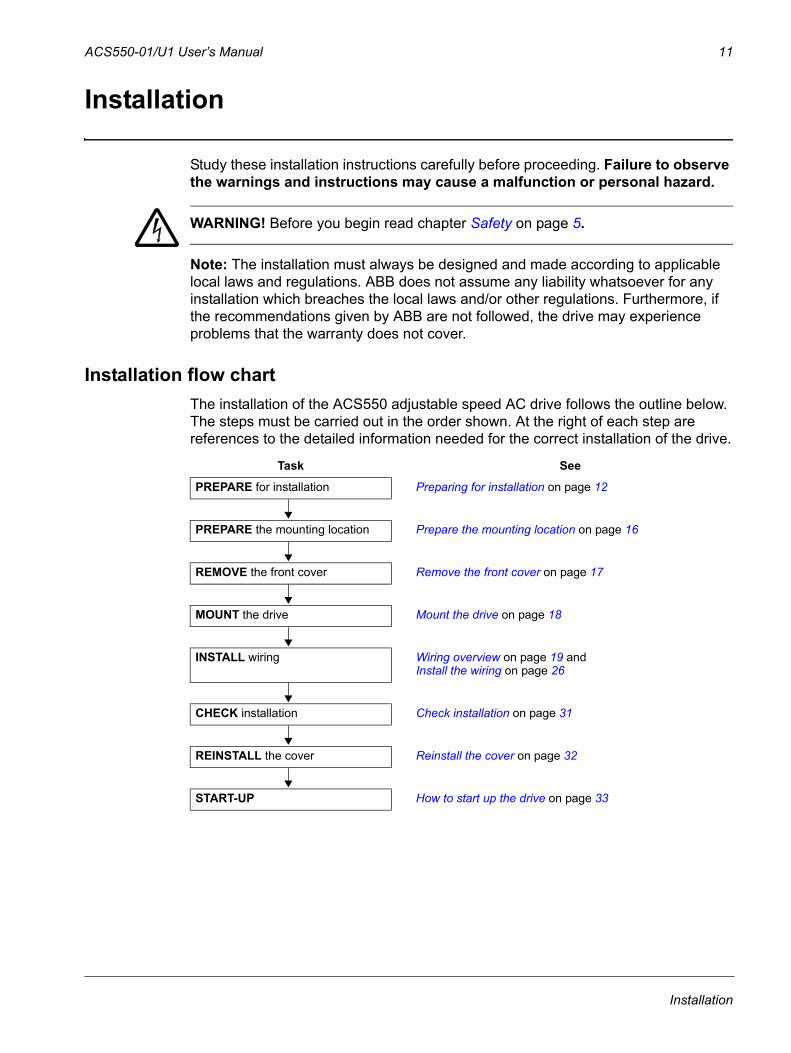
Installation flow chartThe installation of the ACS550 adjustable speed AC drive follows the outline below. The steps must be carried out in the order shown. At the right of each step are references to the detailed information needed for the correct installation of the drive.
Task See
PREPARE for installation Preparing for installation on page 12
PREPARE the mounting location Prepare the mounting location on page 16
REMOVE the front cover Remove the front cover on page 17
MOUNT the drive Mount the drive on page 18
INSTALL wiring Wiring overview on page 19 and Install the wiring on page 26
CHECK installation Check installation on page 31
REINSTALL the cover Reinstall the cover on page 32
START-UP How to start up the drive on page 33
Installation
12 ACS550-01/U1 User’s Manual
Preparing for installation
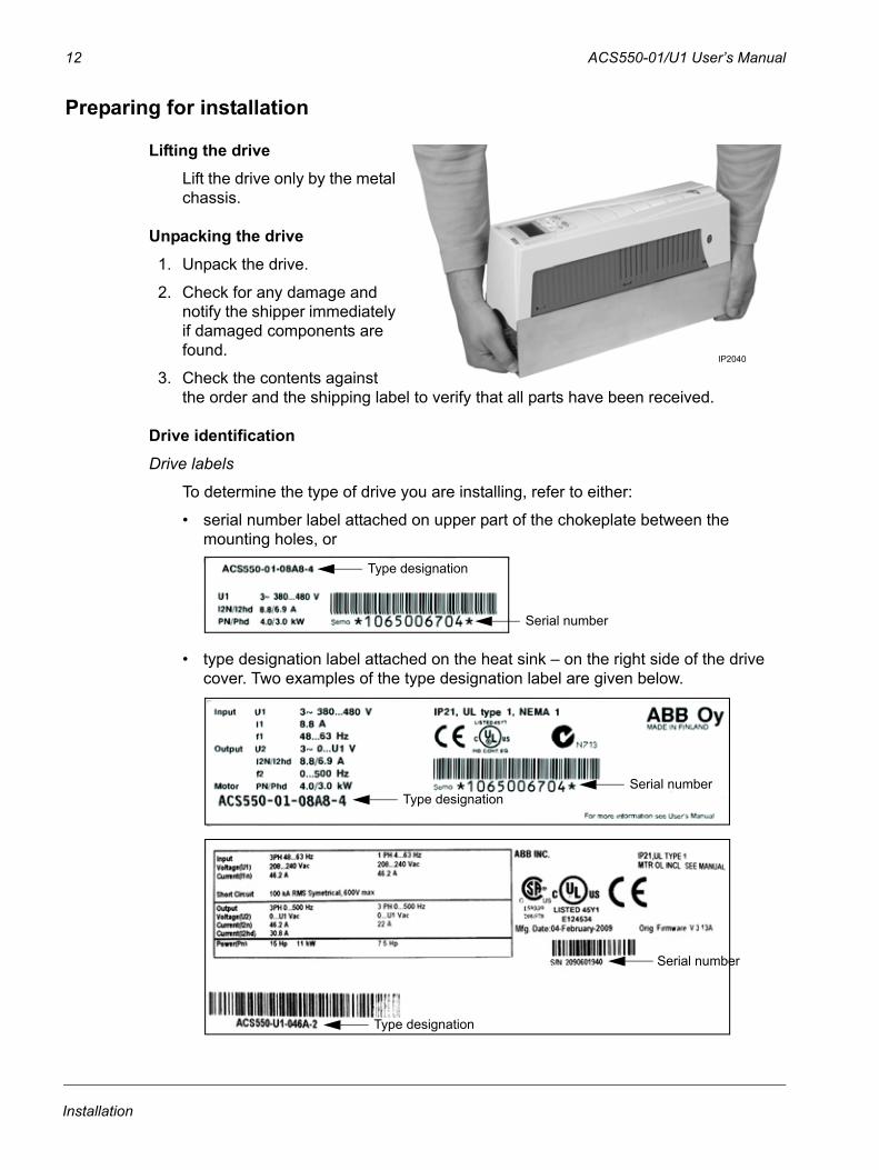
Lifting the driveLift the drive only by the metal chassis.
Unpacking the drive1. Unpack the drive.
2. Check for any damage and notify the shipper immediately if damaged components are found.
3. Check the contents against the order and the shipping label to verify that all parts have been received.
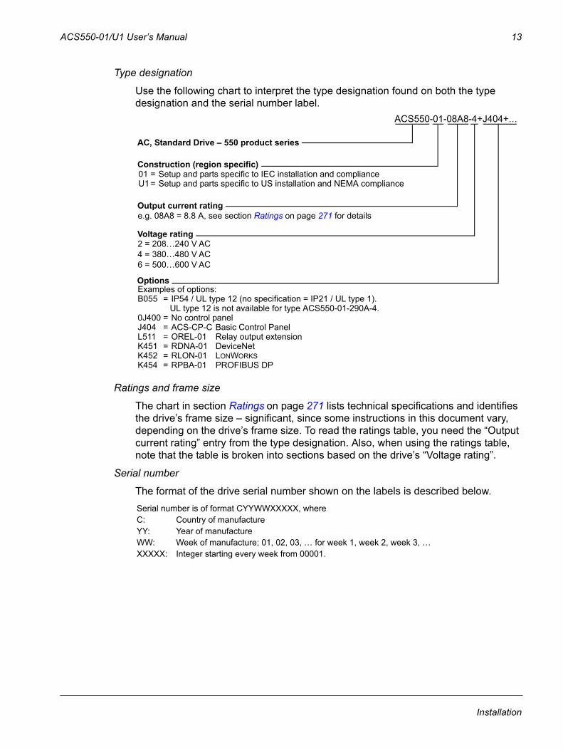
Drive identificationDrive labels
To determine the type of drive you are installing, refer to either:
• serial number label attached on upper part of the chokeplate between the mounting holes, or
• type designation label attached on the heat sink – on the right side of the drive cover. Two examples of the type designation label are given below.
IP2040
Serial number
Type designation
Serial numberType designation
Type designation
Serial number
Installation
ACS550-01/U1 User’s Manual 13
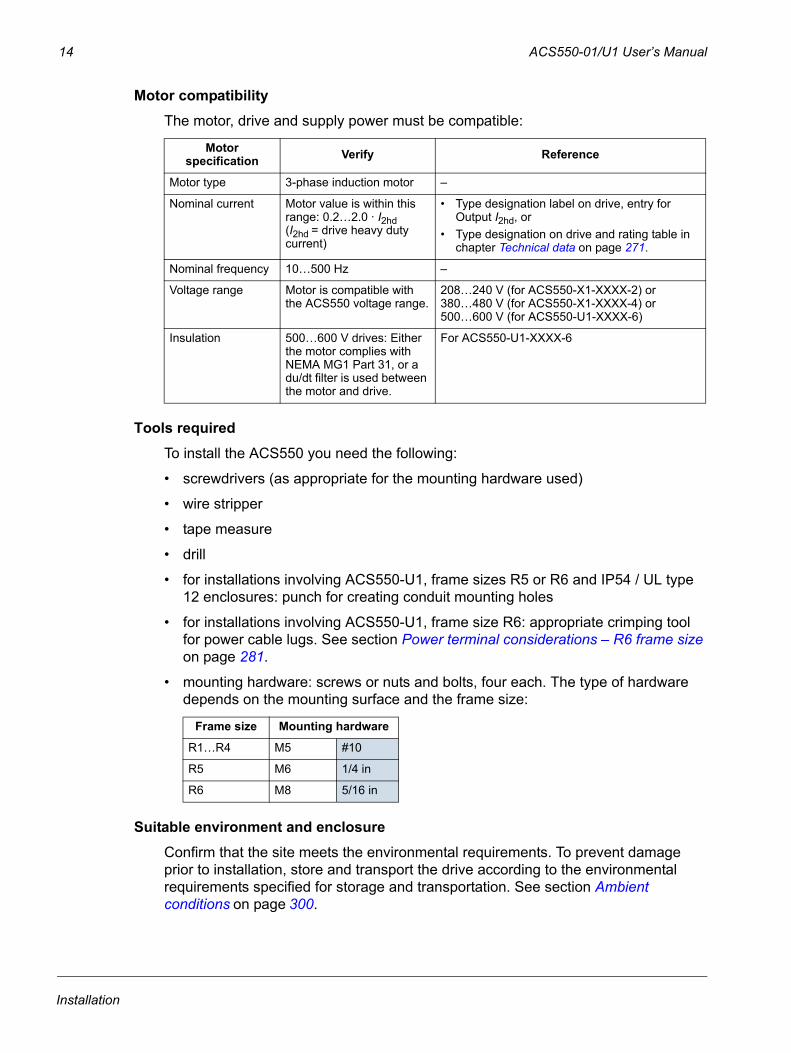
Type designation
Use the following chart to interpret the type designation found on both the type designation and the serial number label.
Ratings and frame size
The chart in section Ratings on page 271 lists technical specifications and identifies the drive’s frame size – significant, since some instructions in this document vary, depending on the drive’s frame size. To read the ratings table, you need the “Output current rating” entry from the type designation. Also, when using the ratings table, note that the table is broken into sections based on the drive’s “Voltage rating”.
Serial number
The format of the drive serial number shown on the labels is described below. Serial number is of format CYYWWXXXXX, where C: Country of manufactureYY: Year of manufactureWW: Week of manufacture; 01, 02, 03, … for week 1, week 2, week 3, …XXXXX: Integer starting every week from 00001.
AC, Standard Drive – 550 product series
Construction (region specific)
Output current rating
Voltage rating
OptionsExamples of options:B055 = IP54 / UL type 12 (no specification = IP21 / UL type 1).
UL type 12 is not available for type ACS550-01-290A-4.0J400 = No control panelJ404 = ACS-CP-C Basic Control Panel L511 = OREL-01 Relay output extensionK451 = RDNA-01 DeviceNetK452 = RLON-01 LONWORKSK454 = RPBA-01 PROFIBUS DP
ACS550-01-08A8-4+J404+…
e.g. 08A8 = 8.8 A, see section Ratings on page 271 for details
2 = 208…240 V AC4 = 380…480 V AC6 = 500…600 V AC
01 = Setup and parts specific to IEC installation and complianceU1 = Setup and parts specific to US installation and NEMA compliance
Installation
14 ACS550-01/U1 User’s Manual
Motor compatibilityThe motor, drive and supply power must be compatible:
Tools requiredTo install the ACS550 you need the following:
• screwdrivers (as appropriate for the mounting hardware used)
• wire stripper
• tape measure
• drill
• for installations involving ACS550-U1, frame sizes R5 or R6 and IP54 / UL type 12 enclosures: punch for creating conduit mounting holes
• for installations involving ACS550-U1, frame size R6: appropriate crimping tool for power cable lugs. See section Power terminal considerations – R6 frame size on page 281.
• mounting hardware: screws or nuts and bolts, four each. The type of hardware depends on the mounting surface and the frame size:
Suitable environment and enclosureConfirm that the site meets the environmental requirements. To prevent damage prior to installation, store and transport the drive according to the environmental requirements specified for storage and transportation. See section Ambient conditions on page 300.
Motor specification Verify Reference
Motor type 3-phase induction motor –
Nominal current Motor value is within this range: 0.2…2.0 · I2hd (I2hd = drive heavy duty current)
• Type designation label on drive, entry for Output I2hd, or
• Type designation on drive and rating table in chapter Technical data on page 271.
Nominal frequency 10…500 Hz –
Voltage range Motor is compatible with the ACS550 voltage range.
208…240 V (for ACS550-X1-XXXX-2) or 380…480 V (for ACS550-X1-XXXX-4) or500…600 V (for ACS550-U1-XXXX-6)
Insulation 500…600 V drives: Either the motor complies with NEMA MG1 Part 31, or a du/dt filter is used between the motor and drive.
For ACS550-U1-XXXX-6
Frame size Mounting hardware
R1…R4 M5 #10
R5 M6 1/4 in
R6 M8 5/16 in
Installation
ACS550-01/U1 User’s Manual 15
Confirm that the enclosure is appropriate, based on the site contamination level:
• IP21 / UL type 1 enclosure: The site must be free of airborne dust, corrosive gases or liquids, and conductive contaminants such as dripping water, condensation, carbon dust and metallic particles.
• IP54 / UL type 12 enclosure: This enclosure provides protection from airborne dust and light sprays or splashing water from all directions.
• If, for some reason, an IP21 drive needs to be installed without the conduit box or cover, or an IP54 drive without the conduit plate or hood, see the note in chapter Technical data, page 304.
Suitable mounting locationConfirm that the mounting location meets the following constraints:
• The drive must be mounted vertically on a smooth, solid surface, and in a suitable environment as defined above. For horizontal installation, contact your local ABB representative for more information.
• The minimum space requirements for the drive are the outside dimensions (see section Outside dimensions on page 298), plus air flow space around the drive (see section Cooling on page 295).
• The distance between the motor and the drive is limited by the maximum motor cable length. See section Motor connection specifications on page 283.
• The mounting site must support the drive’s modest weight. See section Weight on page 299.
Installation
16 ACS550-01/U1 User’s Manual
Installing the drive
WARNING! Before installing the ACS550, ensure the input power supply to the drive is off.
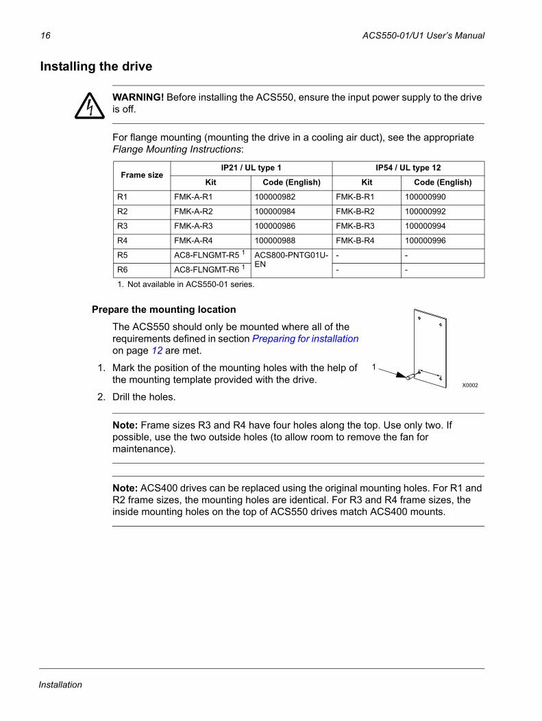
For flange mounting (mounting the drive in a cooling air duct), see the appropriate Flange Mounting Instructions:
Prepare the mounting locationThe ACS550 should only be mounted where all of the requirements defined in section Preparing for installation on page 12 are met.
1. Mark the position of the mounting holes with the help of the mounting template provided with the drive.
2. Drill the holes.
Note: Frame sizes R3 and R4 have four holes along the top. Use only two. If possible, use the two outside holes (to allow room to remove the fan for maintenance).
Note: ACS400 drives can be replaced using the original mounting holes. For R1 and R2 frame sizes, the mounting holes are identical. For R3 and R4 frame sizes, the inside mounting holes on the top of ACS550 drives match ACS400 mounts.
Frame sizeIP21 / UL type 1 IP54 / UL type 12
Kit Code (English) Kit Code (English)
R1 FMK-A-R1 100000982 FMK-B-R1 100000990
R2 FMK-A-R2 100000984 FMK-B-R2 100000992
R3 FMK-A-R3 100000986 FMK-B-R3 100000994
R4 FMK-A-R4 100000988 FMK-B-R4 100000996
R5 AC8-FLNGMT-R5 1 ACS800-PNTG01U-EN
- -
R6 AC8-FLNGMT-R6 1 - -
1. Not available in ACS550-01 series.
X0002
1
Installation
ACS550-01/U1 User’s Manual 17
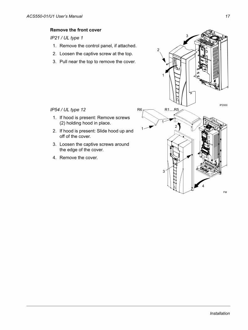
Remove the front coverIP21 / UL type 1
1. Remove the control panel, if attached.
2. Loosen the captive screw at the top.
3. Pull near the top to remove the cover.
IP54 / UL type 12
1. If hood is present: Remove screws (2) holding hood in place.
2. If hood is present: Slide hood up and off of the cover.
3. Loosen the captive screws around the edge of the cover.
4. Remove the cover.
3
IP2000
1
2
3
4
12
FM
R6
1
R1…R5
Installation
18 ACS550-01/U1 User’s Manual
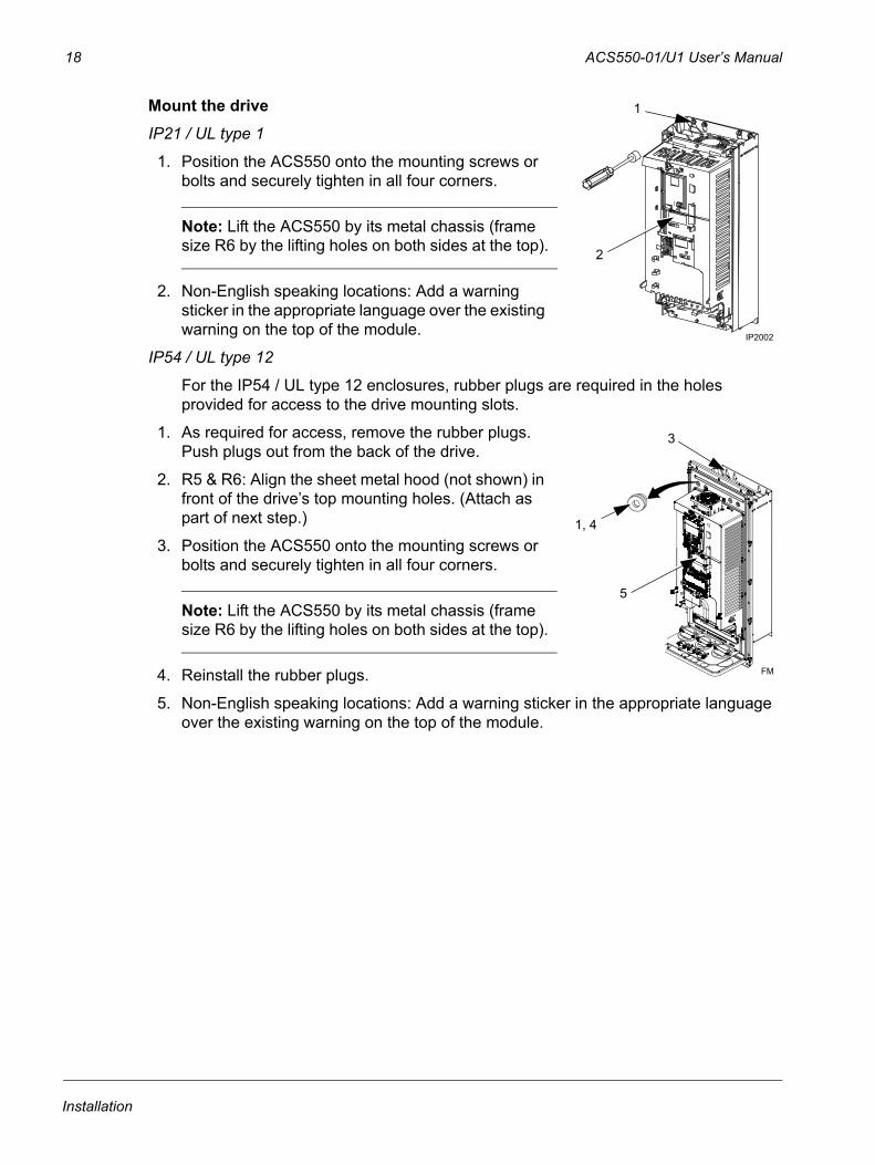
Mount the driveIP21 / UL type 1
1. Position the ACS550 onto the mounting screws or bolts and securely tighten in all four corners.
Note: Lift the ACS550 by its metal chassis (frame size R6 by the lifting holes on both sides at the top).
2. Non-English speaking locations: Add a warning sticker in the appropriate language over the existing warning on the top of the module.
IP54 / UL type 12
For the IP54 / UL type 12 enclosures, rubber plugs are required in the holes provided for access to the drive mounting slots.
1. As required for access, remove the rubber plugs. Push plugs out from the back of the drive.
2. R5 & R6: Align the sheet metal hood (not shown) in front of the drive’s top mounting holes. (Attach as part of next step.)
3. Position the ACS550 onto the mounting screws or bolts and securely tighten in all four corners.
Note: Lift the ACS550 by its metal chassis (frame size R6 by the lifting holes on both sides at the top).
4. Reinstall the rubber plugs.
5. Non-English speaking locations: Add a warning sticker in the appropriate language over the existing warning on the top of the module.
IP2002
1
2
3
1, 4
FM
5
Installation
ACS550-01/U1 User’s Manual 19
Wiring overviewConduit/Gland kit
Wiring drives with the IP21 / UL type 1 enclosure requires a conduit/gland kit with the following items:
• conduit/gland box
• five (5) cable clamps (ACS550-01 only)
• screws
• cover.
The kit is included with IP21 / UL type 1 enclosures.
Wiring requirements
WARNING! Ensure the motor is compatible for use with the ACS550. The drive must be installed by a competent person in accordance with the considerations defined in section Preparing for installation on page 12. If in doubt, contact your local ABB sales or service office.
As you install the wiring, observe the following:
• There are four sets of wiring instructions – one set for each combination of drive enclosure type (IP21 / UL type and IP54 / UL type 12) and wiring type (conduit or cable). Be sure to select the appropriate procedure.
• Determine electro-magnetic compliance (EMC) requirements per local codes. See section Motor cable requirements for CE & C-Tick compliance on page 287. In general:
– Follow local codes for cable size.– Keep these four classes of wiring separated: input power wiring, motor wiring,
control/communications wiring and braking unit wiring.• When installing input power and motor wiring, refer to the following, as
appropriate:
• To locate input power and motor connection terminals, see section Power connection diagrams on page 21. For specifications on power terminals, see section Drive’s power connection terminals on page 280.
• For corner grounded TN systems, see section Corner grounded TN systems on page 279.
• For IT systems, see section IT systems on page 280.
Terminal Description Specifications and notes
U1, V1, W11 3-phase power supply input Input power connections on page 275
PE Protective Ground Ground connections on page 279
U2, V2, W2 Power output to motor Motor connections on page 283 1 The ACS550 -x1-xxxx-2 (208…240 V series) can be used with a single phase supply, if output
current is derated by 50%. For single phase supply voltage, connect power at U1 and W1.
Installation
20 ACS550-01/U1 User’s Manual
• For frame size R6, see section Power terminal considerations – R6 frame size on page 281 to install the appropriate cable lugs.
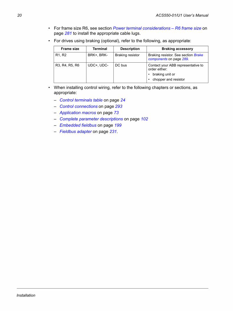
• For drives using braking (optional), refer to the following, as appropriate:
• When installing control wiring, refer to the following chapters or sections, as appropriate:
– Control terminals table on page 24– Control connections on page 293– Application macros on page 73– Complete parameter descriptions on page 102– Embedded fieldbus on page 199– Fieldbus adapter on page 231.
Frame size Terminal Description Braking accessory
R1, R2 BRK+, BRK- Braking resistor Braking resistor. See section Brake components on page 289.
R3, R4, R5, R6 UDC+, UDC- DC bus Contact your ABB representative to order either:• braking unit or• chopper and resistor
Installation
ACS550-01/U1 User’s Manual 21
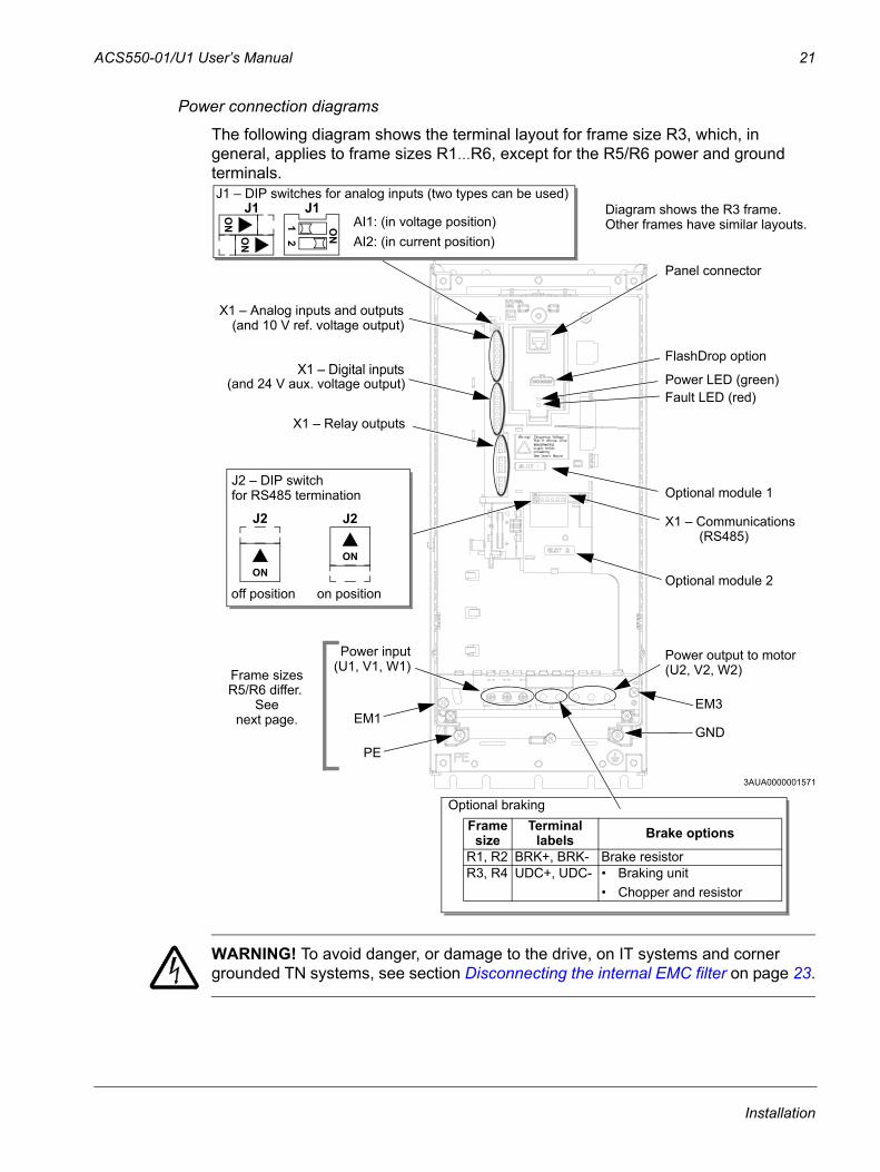
Power connection diagrams
The following diagram shows the terminal layout for frame size R3, which, in general, applies to frame sizes R1…R6, except for the R5/R6 power and ground terminals.
WARNING! To avoid danger, or damage to the drive, on IT systems and corner grounded TN systems, see section Disconnecting the internal EMC filter on page 23.
Panel connector
Fault LED (red)
Optional module 1J2 – DIP switch
X1 – Communications
Optional module 2
GND
Power output to motorPower input
EM1
X1 – Analog inputs and outputs
X1 – Digital inputs
X1 – Relay outputs
J2
ON
off position on position
for RS485 termination
(and 10 V ref. voltage output)
(and 24 V aux. voltage output)
PE
(U1, V1, W1) (U2, V2, W2)
Optional brakingFrame
sizeTerminal
labels Brake options
R1, R2 BRK+, BRK- Brake resistorR3, R4 UDC+, UDC- • Braking unit
• Chopper and resistor
(RS485)
R5/R6 differ. See
Frame sizes
next page.
Diagram shows the R3 frame.
J2
ON
Other frames have similar layouts. J1
AI1: (in voltage position)AI2: (in current position)
ON
ON
J1 – DIP switches for analog inputs (two types can be used)
ON
12
J1
FlashDrop option
Power LED (green)
3AUA0000001571
EM3
Installation
22 ACS550-01/U1 User’s Manual
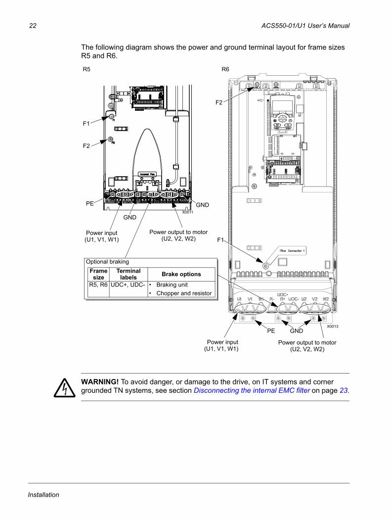
The following diagram shows the power and ground terminal layout for frame sizes R5 and R6.
WARNING! To avoid danger, or damage to the drive, on IT systems and corner grounded TN systems, see section Disconnecting the internal EMC filter on page 23.
GND
Power input
PE
(U1, V1, W1)
Optional brakingFrame
sizeTerminal
labels Brake options
R5, R6 UDC+, UDC- • Braking unit • Chopper and resistor
X0011
F2
Power input
PE
(U1, V1, W1)
F1
F2
X0013
Power output to motor(U2, V2, W2)
R5 R6
GND
GND
Power output to motor(U2, V2, W2)
F1
Installation
ACS550-01/U1 User’s Manual 23
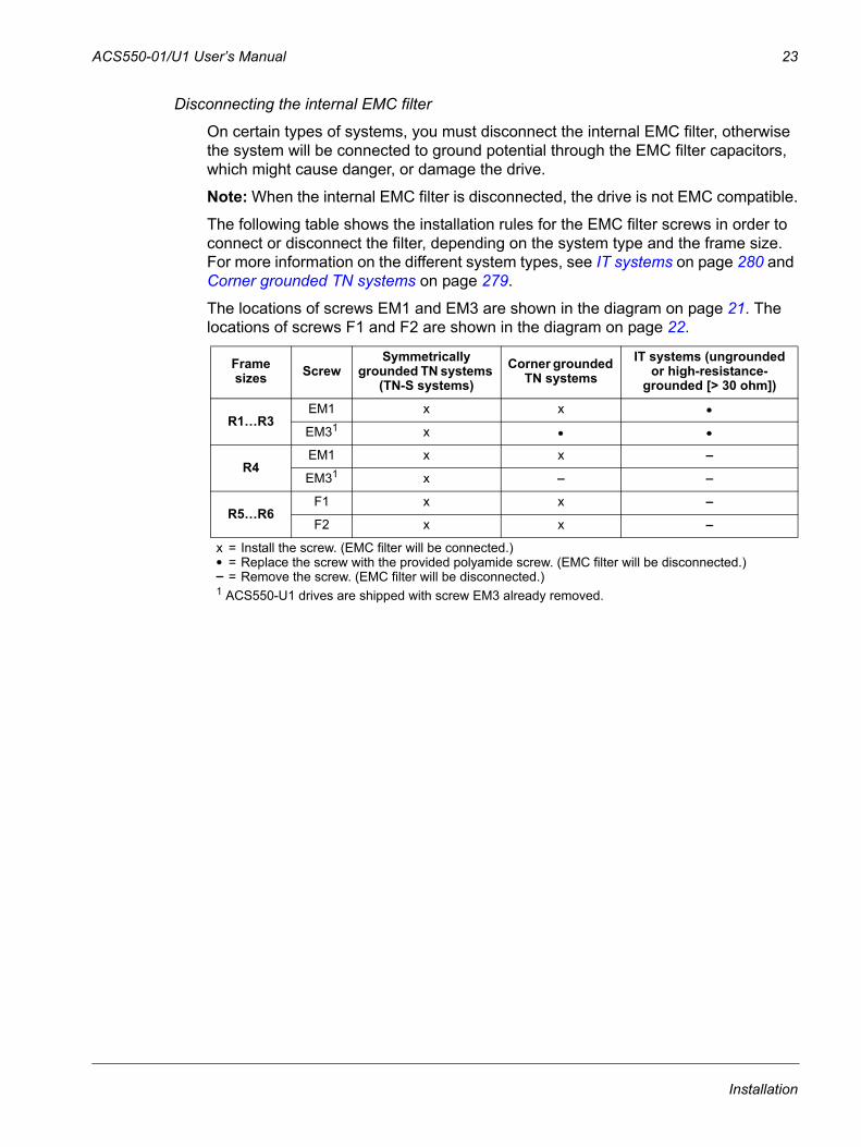
Disconnecting the internal EMC filter
On certain types of systems, you must disconnect the internal EMC filter, otherwise the system will be connected to ground potential through the EMC filter capacitors, which might cause danger, or damage the drive.
Note: When the internal EMC filter is disconnected, the drive is not EMC compatible.
The following table shows the installation rules for the EMC filter screws in order to connect or disconnect the filter, depending on the system type and the frame size. For more information on the different system types, see IT systems on page 280 and Corner grounded TN systems on page 279.
The locations of screws EM1 and EM3 are shown in the diagram on page 21. The locations of screws F1 and F2 are shown in the diagram on page 22.
Frame sizes Screw
Symmetrically grounded TN systems
(TN-S systems)Corner grounded
TN systemsIT systems (ungrounded
or high-resistance-grounded [> 30 ohm])
R1…R3EM1 x x
EM31 x
R4EM1 x x –
EM31 x – –
R5…R6F1 x x –
F2 x x –
x = Install the screw. (EMC filter will be connected.)= Replace the screw with the provided polyamide screw. (EMC filter will be disconnected.)
– = Remove the screw. (EMC filter will be disconnected.)1 ACS550-U1 drives are shipped with screw EM3 already removed.
Installation
24 ACS550-01/U1 User’s Manual
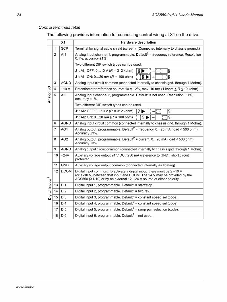
Control terminals table
The following provides information for connecting control wiring at X1 on the drive.
X1 Hardware description
1 SCR Terminal for signal cable shield (screen). (Connected internally to chassis ground.)
2 AI1 Analog input channel 1, programmable. Default2 = frequency reference. Resolution 0.1%, accuracy ±1%.
Two different DIP switch types can be used.
J1: AI1 OFF: 0…10 V (Ri = 312 kohm)
J1: AI1 ON: 0…20 mA (Ri = 100 ohm)
3 AGND Analog input circuit common (connected internally to chassis gnd. through 1 Mohm).
4 +10 V Potentiometer reference source: 10 V ±2%, max. 10 mA (1 kohm < R < 10 kohm).
5 AI2 Analog input channel 2, programmable. Default2 = not used. Resolution 0.1%, accuracy ±1%.
Two different DIP switch types can be used.
J1: AI2 OFF: 0…10 V (Ri = 312 kohm)
J1: AI2 ON: 0…20 mA (Ri = 100 ohm)
6 AGND Analog input circuit common (connected internally to chassis gnd. through 1 Mohm).
7 AO1 Analog output, programmable. Default2 = frequency. 0…20 mA (load < 500 ohm). Accuracy ±3%.
8 AO2 Analog output, programmable. Default2 = current. 0…20 mA (load < 500 ohm). Accuracy ±3%.
9 AGND Analog output circuit common (connected internally to chassis gnd. through 1 Mohm).
10 +24V Auxiliary voltage output 24 V DC / 250 mA (reference to GND), short circuit protected.
11 GND Auxiliary voltage output common (connected internally as floating).
12 DCOM Digital input common. To activate a digital input, there must be ≥ +10 V (or ≤ -10 V) between that input and DCOM. The 24 V may be provided by the ACS550 (X1-10) or by an external 12…24 V source of either polarity.
13 DI1 Digital input 1, programmable. Default2 = start/stop.
14 DI2 Digital input 2, programmable. Default2 = fwd/rev.
15 DI3 Digital input 3, programmable. Default2 = constant speed sel (code).
16 DI4 Digital input 4, programmable. Default2 = constant speed sel (code).
17 DI5 Digital input 5, programmable. Default2 = ramp pair selection (code).
18 DI6 Digital input 6, programmable. Default2 = not used.
Ana
log
I/O
ON 1 ON
ON 1 ON
ON 1 ON
ON 1 ON
Dig
ital i
nput
s1
Installation
ACS550-01/U1 User’s Manual 25
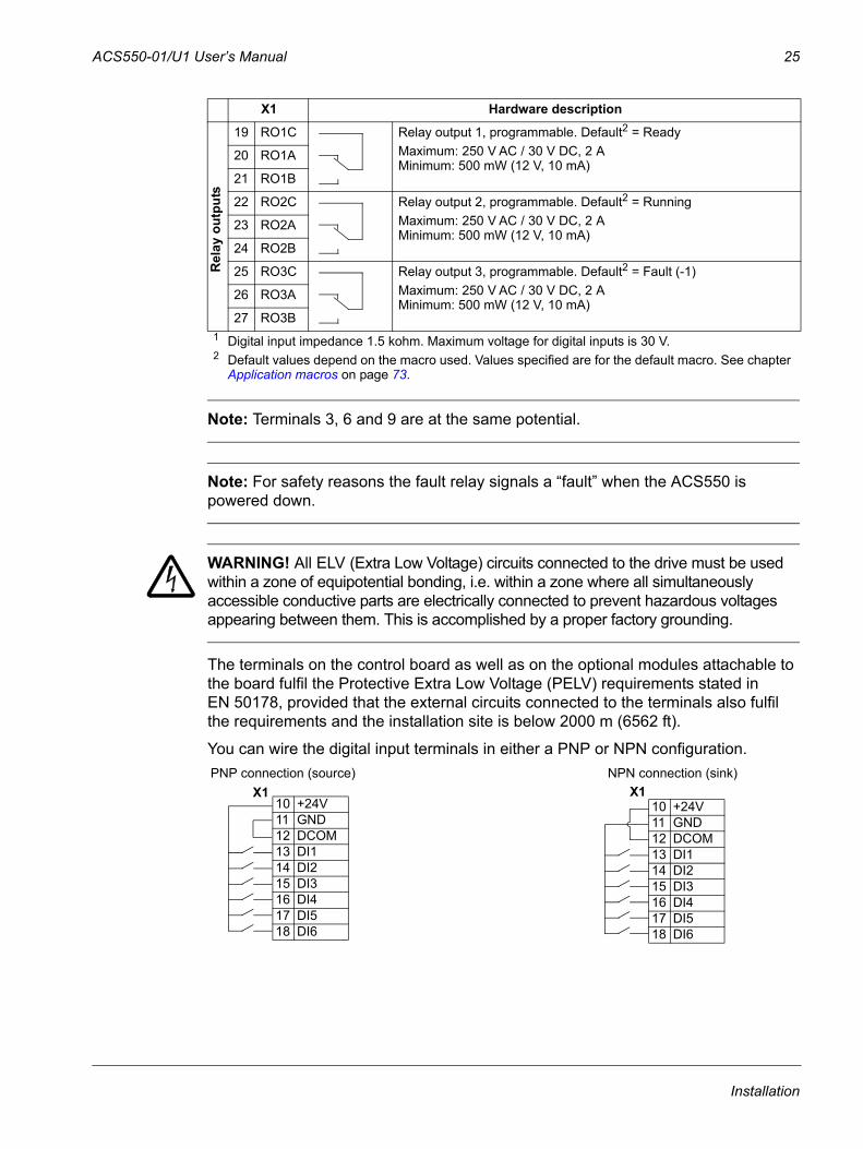
Note: Terminals 3, 6 and 9 are at the same potential.
Note: For safety reasons the fault relay signals a “fault” when the ACS550 is powered down.
WARNING! All ELV (Extra Low Voltage) circuits connected to the drive must be used within a zone of equipotential bonding, i.e. within a zone where all simultaneously accessible conductive parts are electrically connected to prevent hazardous voltages appearing between them. This is accomplished by a proper factory grounding.
The terminals on the control board as well as on the optional modules attachable to the board fulfil the Protective Extra Low Voltage (PELV) requirements stated in EN 50178, provided that the external circuits connected to the terminals also fulfil the requirements and the installation site is below 2000 m (6562 ft).
You can wire the digital input terminals in either a PNP or NPN configuration.
19 RO1C Relay output 1, programmable. Default2 = ReadyMaximum: 250 V AC / 30 V DC, 2 AMinimum: 500 mW (12 V, 10 mA)
20 RO1A
21 RO1B
22 RO2C Relay output 2, programmable. Default2 = RunningMaximum: 250 V AC / 30 V DC, 2 AMinimum: 500 mW (12 V, 10 mA)
23 RO2A
24 RO2B
25 RO3C Relay output 3, programmable. Default2 = Fault (-1)Maximum: 250 V AC / 30 V DC, 2 AMinimum: 500 mW (12 V, 10 mA)
26 RO3A
27 RO3B1 Digital input impedance 1.5 kohm. Maximum voltage for digital inputs is 30 V.2 Default values depend on the macro used. Values specified are for the default macro. See chapter
Application macros on page 73.
X1 Hardware description
Rel
ay o
utpu
ts
NPN connection (sink)PNP connection (source) 10 +24V11 GND12 DCOM13 DI114 DI215 DI316 DI417 DI518 DI6
10 +24V11 GND12 DCOM13 DI114 DI215 DI316 DI417 DI518 DI6
X1X1
Installation
26 ACS550-01/U1 User’s Manual
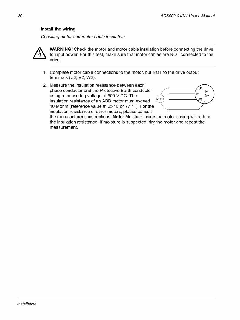
Install the wiringChecking motor and motor cable insulation
WARNING! Check the motor and motor cable insulation before connecting the drive to input power. For this test, make sure that motor cables are NOT connected to the drive.
1. Complete motor cable connections to the motor, but NOT to the drive output terminals (U2, V2, W2).
2. Measure the insulation resistance between each phase conductor and the Protective Earth conductor using a measuring voltage of 500 V DC. The insulation resistance of an ABB motor must exceed 10 Mohm (reference value at 25 °C or 77 °F). For the insulation resistance of other motors, please consult the manufacturer’s instructions. Note: Moisture inside the motor casing will reduce the insulation resistance. If moisture is suspected, dry the motor and repeat the measurement.
ohm
M3~
U1
V1
W1 PE
Installation
ACS550-01/U1 User’s Manual 27
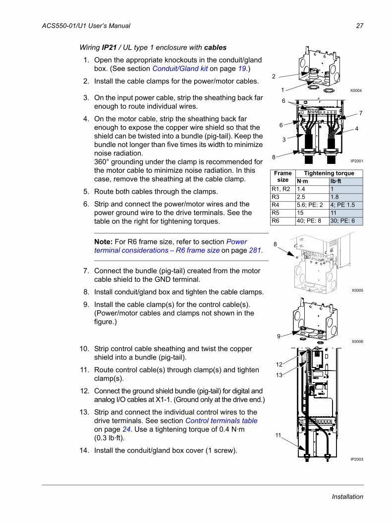
Wiring IP21 / UL type 1 enclosure with cables
1. Open the appropriate knockouts in the conduit/gland box. (See section Conduit/Gland kit on page 19.)
2. Install the cable clamps for the power/motor cables.
3. On the input power cable, strip the sheathing back far enough to route individual wires.
4. On the motor cable, strip the sheathing back far enough to expose the copper wire shield so that the shield can be twisted into a bundle (pig-tail). Keep the bundle not longer than five times its width to minimize noise radiation.360° grounding under the clamp is recommended for the motor cable to minimize noise radiation. In this case, remove the sheathing at the cable clamp.
5. Route both cables through the clamps.
6. Strip and connect the power/motor wires and the power ground wire to the drive terminals. See the table on the right for tightening torques.
Note: For R6 frame size, refer to section Power terminal considerations – R6 frame size on page 281.
7. Connect the bundle (pig-tail) created from the motor cable shield to the GND terminal.
8. Install conduit/gland box and tighten the cable clamps.
9. Install the cable clamp(s) for the control cable(s). (Power/motor cables and clamps not shown in the figure.)
10. Strip control cable sheathing and twist the copper shield into a bundle (pig-tail).
11. Route control cable(s) through clamp(s) and tighten clamp(s).
12. Connect the ground shield bundle (pig-tail) for digital and analog I/O cables at X1-1. (Ground only at the drive end.)
13. Strip and connect the individual control wires to the drive terminals. See section Control terminals table on page 24. Use a tightening torque of 0.4 N·m (0.3 lb·ft).
14. Install the conduit/gland box cover (1 screw).
1
2
X0004
6
3
IP2001
6
7
4
8
8
X0005
Frame size
Tightening torqueN·m lb·ft
R1, R2 1.4 1R3 2.5 1.8R4 5.6; PE: 2 4; PE 1.5R5 15 11R6 40; PE: 8 30; PE: 6
9X0006
12
IP2003
11
13
Installation
28 ACS550-01/U1 User’s Manual
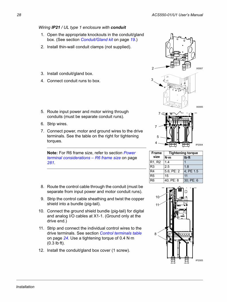
Wiring IP21 / UL type 1 enclosure with conduit
1. Open the appropriate knockouts in the conduit/gland box. (See section Conduit/Gland kit on page 19.)
2. Install thin-wall conduit clamps (not supplied).
3. Install conduit/gland box.
4. Connect conduit runs to box.
5. Route input power and motor wiring through conduits (must be separate conduit runs).
6. Strip wires.
7. Connect power, motor and ground wires to the drive terminals. See the table on the right for tightening torques.
Note: For R6 frame size, refer to section Power terminal considerations – R6 frame size on page 281.
8. Route the control cable through the conduit (must be separate from input power and motor conduit runs).
9. Strip the control cable sheathing and twist the copper shield into a bundle (pig-tail).
10. Connect the ground shield bundle (pig-tail) for digital and analog I/O cables at X1-1. (Ground only at the drive end.)
11. Strip and connect the individual control wires to the drive terminals. See section Control terminals table on page 24. Use a tightening torque of 0.4 N·m (0.3 lb·ft).
12. Install the conduit/gland box cover (1 screw).
2 X0007
3
X0005
4IP2004
7
7
5
Frame size
Tightening torqueN·m lb·ft
R1, R2 1.4 1R3 2.5 1.8R4 5.6; PE: 2 4; PE 1.5R5 15 11R6 40; PE: 8 30; PE: 6
10
8
IP2005
11
Installation
ACS550-01/U1 User’s Manual 29
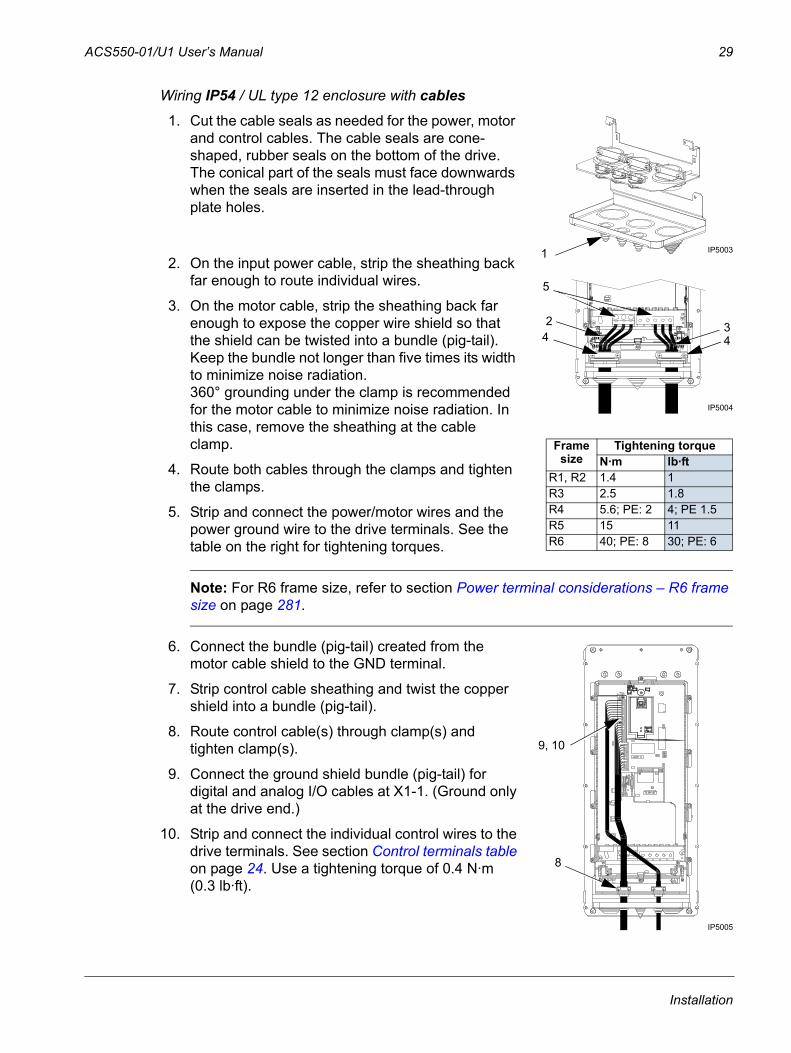
Wiring IP54 / UL type 12 enclosure with cables
1. Cut the cable seals as needed for the power, motor and control cables. The cable seals are cone-shaped, rubber seals on the bottom of the drive. The conical part of the seals must face downwards when the seals are inserted in the lead-through plate holes.
2. On the input power cable, strip the sheathing back far enough to route individual wires.
3. On the motor cable, strip the sheathing back far enough to expose the copper wire shield so that the shield can be twisted into a bundle (pig-tail). Keep the bundle not longer than five times its width to minimize noise radiation.360° grounding under the clamp is recommended for the motor cable to minimize noise radiation. In this case, remove the sheathing at the cable clamp.
4. Route both cables through the clamps and tighten the clamps.
5. Strip and connect the power/motor wires and the power ground wire to the drive terminals. See the table on the right for tightening torques.
Note: For R6 frame size, refer to section Power terminal considerations – R6 frame size on page 281.
6. Connect the bundle (pig-tail) created from the motor cable shield to the GND terminal.
7. Strip control cable sheathing and twist the copper shield into a bundle (pig-tail).
8. Route control cable(s) through clamp(s) and tighten clamp(s).
9. Connect the ground shield bundle (pig-tail) for digital and analog I/O cables at X1-1. (Ground only at the drive end.)
10. Strip and connect the individual control wires to the drive terminals. See section Control terminals table on page 24. Use a tightening torque of 0.4 N·m (0.3 lb·ft).
1 IP5003
4
5
2
IP5004
34
Frame size
Tightening torqueN·m lb·ft
R1, R2 1.4 1R3 2.5 1.8R4 5.6; PE: 2 4; PE 1.5R5 15 11R6 40; PE: 8 30; PE: 6
8
IP5005
9, 10
Installation
30 ACS550-01/U1 User’s Manual
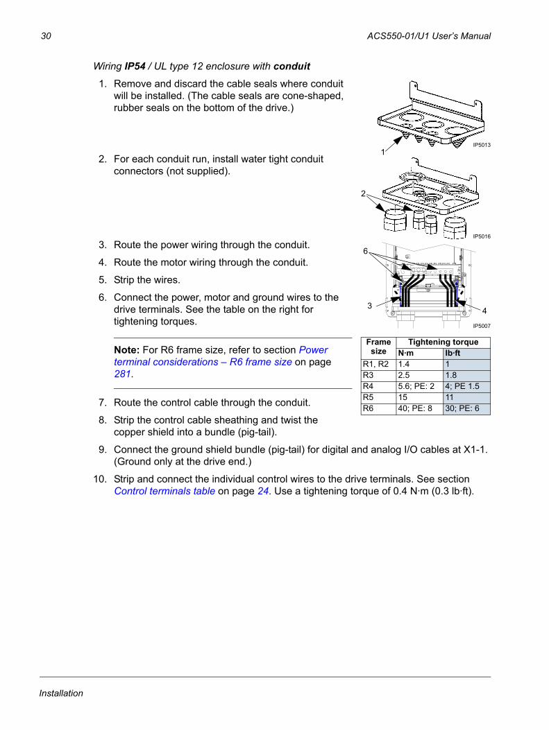
Wiring IP54 / UL type 12 enclosure with conduit
1. Remove and discard the cable seals where conduit will be installed. (The cable seals are cone-shaped, rubber seals on the bottom of the drive.)
2. For each conduit run, install water tight conduit connectors (not supplied).
3. Route the power wiring through the conduit.
4. Route the motor wiring through the conduit.
5. Strip the wires.
6. Connect the power, motor and ground wires to the drive terminals. See the table on the right for tightening torques.
Note: For R6 frame size, refer to section Power terminal considerations – R6 frame size on page 281.
7. Route the control cable through the conduit.
8. Strip the control cable sheathing and twist the copper shield into a bundle (pig-tail).
9. Connect the ground shield bundle (pig-tail) for digital and analog I/O cables at X1-1. (Ground only at the drive end.)
10. Strip and connect the individual control wires to the drive terminals. See section Control terminals table on page 24. Use a tightening torque of 0.4 N·m (0.3 lb·ft).
IP50131
2
IP5016
3
IP5007
6
4
Frame size
Tightening torqueN·m lb·ft
R1, R2 1.4 1R3 2.5 1.8R4 5.6; PE: 2 4; PE 1.5R5 15 11R6 40; PE: 8 30; PE: 6
Installation
ACS550-01/U1 User’s Manual 31
Check installationBefore applying power, perform the following checks.
Check
Installation environment conforms to the drive’s specifications for ambient conditions.
The drive is mounted securely.
Space around the drive meets the drive’s specifications for cooling.
The motor and driven equipment are ready for start.
For IT systems and corner grounded TN systems: The internal EMC filter is disconnected (see section Disconnecting the internal EMC filter on page 23).
The drive is properly grounded.
The input power (mains) voltage matches the drive nominal input voltage.
The input power (mains) connections at U1, V1 and W1 are connected and tightened as specified.
The input power (mains) fuses are installed.
The motor connections at U2, V2 and W2 are connected and tightened as specified.
The motor cable is routed away from other cables.
NO power factor compensation capacitors are in the motor cable.
The control connections are connected and tightened as specified.
NO tools or foreign objects (such as drill shavings) are inside the drive.
NO alternate power source for the motor (such as a bypass connection) is connected – no voltage is applied to the output of the drive.
Installation
32 ACS550-01/U1 User’s Manual
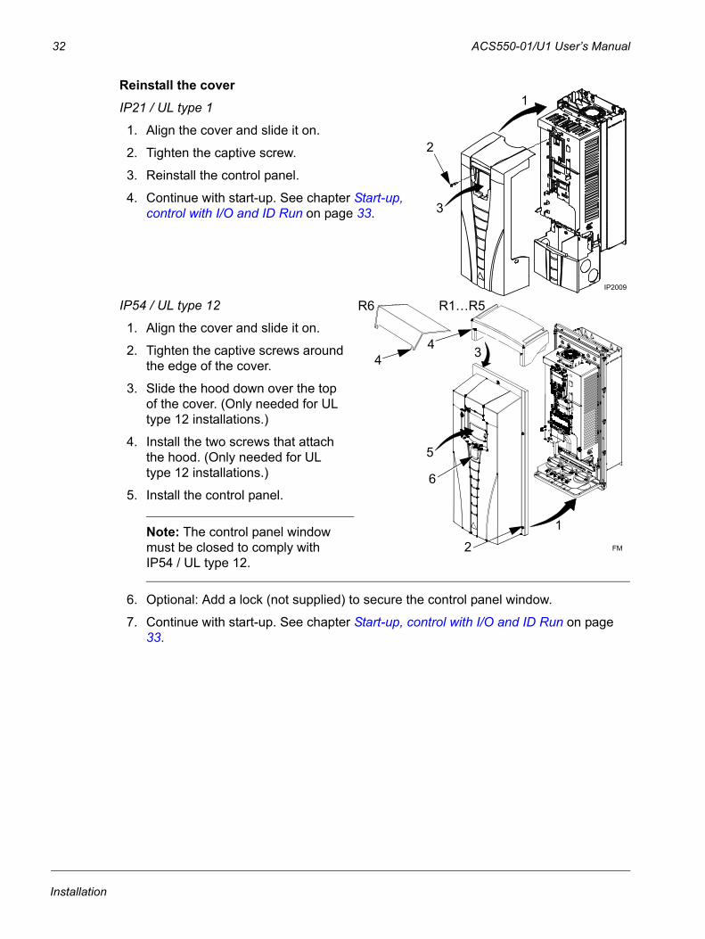
Reinstall the coverIP21 / UL type 1
1. Align the cover and slide it on.
2. Tighten the captive screw.
3. Reinstall the control panel.
4. Continue with start-up. See chapter Start-up, control with I/O and ID Run on page 33.
IP54 / UL type 12
1. Align the cover and slide it on.
2. Tighten the captive screws around the edge of the cover.
3. Slide the hood down over the top of the cover. (Only needed for UL type 12 installations.)
4. Install the two screws that attach the hood. (Only needed for UL type 12 installations.)
5. Install the control panel.
Note: The control panel window must be closed to comply with IP54 / UL type 12.
6. Optional: Add a lock (not supplied) to secure the control panel window.
7. Continue with start-up. See chapter Start-up, control with I/O and ID Run on page 33.
3
1
2
IP2009
R6
4
R1…R5
2
1
4 3
5
6
FM
Installation
ACS550-01/U1 User’s Manual 33
Start-up, control with I/O and ID Run
The chapter instructs how to:
• perform the start-up
• start, stop, change the direction of rotation and adjust the speed of the motor through the I/O interface
• perform an Identification Run for the drive.
Using the control panel to do these tasks is explained briefly in this chapter. For details on how to use the control panel, refer to chapter Control panels starting on page 43.
How to start up the driveHow you start up the drive depends on the control panel you have.
• If you have an Assistant Control Panel, you can either run the Start-up Assistant (see section How to perform the guided start-up on page 38) or perform a limited start-up (see section How to perform the limited start-up on page 33).
The Start-up Assistant, which is included in the Assistant Control Panel only, guides you through all essential settings to be done. In the limited start-up, the drive gives no guidance; you go through the very basic settings by following the instructions given in the manual.
• If you have a Basic Control Panel, follow the instructions given in section How to perform the limited start-up on page 33.
How to perform the limited start-upFor the limited start-up, you can use the Basic Control Panel or the Assistant Control Panel. The instructions below are valid for both control panels, but the displays shown are the Basic Control Panel displays, unless the instruction applies to the Assistant Control Panel only.
Before you start, ensure that you have the motor nameplate data on hand.
SAFETY
The start-up may only be carried out by a qualified electrician.The safety instructions given in chapter Safety must be followed during the start-up procedure.
The drive will start up automatically at power up, if the external run command is on.
Check the installation. See the checklist in chapter Installation, page 31.
Start-up, control with I/O and ID Run
34 ACS550-01/U1 User’s Manual
Check that the starting of the motor does not cause any danger. De-couple the driven machine if:• there is a risk of damage in case of incorrect direction of rotation, or • an ID Run needs to be performed during the drive start-up. ID Run is essential only in
applications that require the ultimate in motor control accuracy.
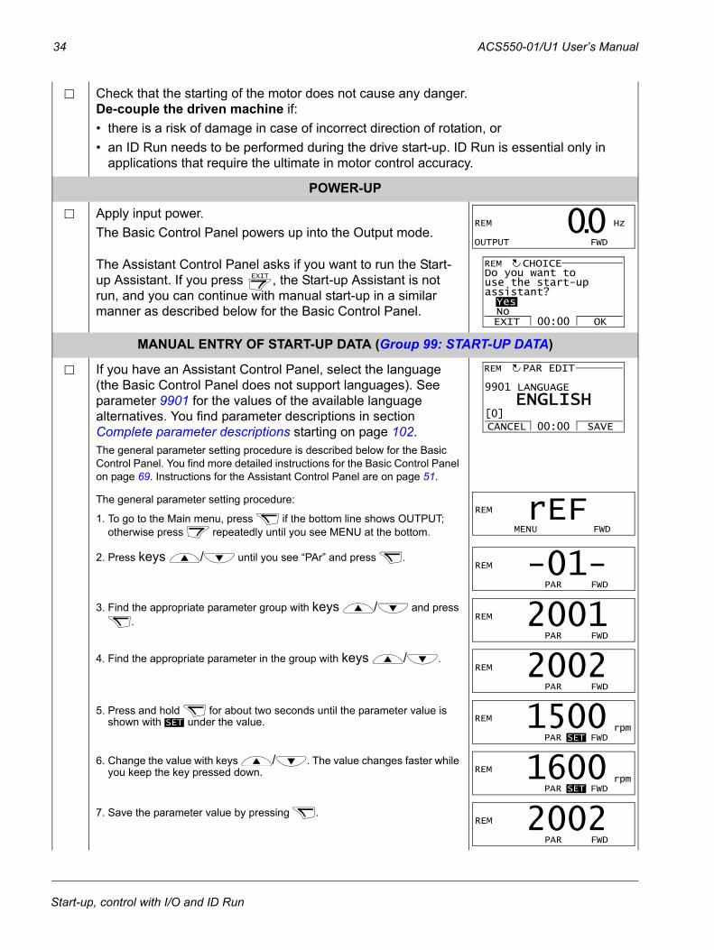
POWER-UP
Apply input power. The Basic Control Panel powers up into the Output mode.
The Assistant Control Panel asks if you want to run the Start-up Assistant. If you press , the Start-up Assistant is not run, and you can continue with manual start-up in a similar manner as described below for the Basic Control Panel.
MANUAL ENTRY OF START-UP DATA (Group 99: START-UP DATA)
If you have an Assistant Control Panel, select the language (the Basic Control Panel does not support languages). See parameter 9901 for the values of the available language alternatives. You find parameter descriptions in section Complete parameter descriptions starting on page 102.The general parameter setting procedure is described below for the Basic Control Panel. You find more detailed instructions for the Basic Control Panel on page 69. Instructions for the Assistant Control Panel are on page 51.
The general parameter setting procedure:
1. To go to the Main menu, press if the bottom line shows OUTPUT; otherwise press repeatedly until you see MENU at the bottom.
2. Press keys / until you see “PAr” and press .
3. Find the appropriate parameter group with keys / and press .
4. Find the appropriate parameter in the group with keys / .
5. Press and hold for about two seconds until the parameter value is shown with under the value.
6. Change the value with keys / . The value changes faster while you keep the key pressed down.
7. Save the parameter value by pressing .
REM Hz
OUTPUT FWD
00.
EXIT
Do you want touse the start-upassistant?YesNoEXIT OK00:00
CHOICEREM
9901 LANGUAGE
PAR EDIT
ENGLISH
CANCEL SAVE00:00[0]
REM
REM
MENU FWD
rEF REM
PAR FWD
-01- REM
PAR FWD
2001 REM
PAR FWD
2002
SET
REM rpm PAR SET FWD
1500 REM rpm PAR SET FWD
1600 REM
PAR FWD
2002
Start-up, control with I/O and ID Run
ACS550-01/U1 User’s Manual 35
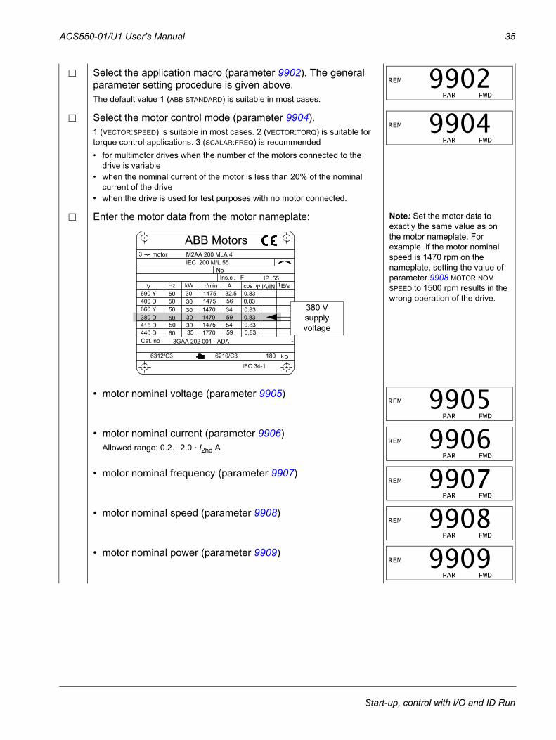
Select the application macro (parameter 9902). The general parameter setting procedure is given above.The default value 1 (ABB STANDARD) is suitable in most cases.
Select the motor control mode (parameter 9904).1 (VECTOR:SPEED) is suitable in most cases. 2 (VECTOR:TORQ) is suitable for torque control applications. 3 (SCALAR:FREQ) is recommended• for multimotor drives when the number of the motors connected to the
drive is variable• when the nominal current of the motor is less than 20% of the nominal
current of the drive• when the drive is used for test purposes with no motor connected.
Enter the motor data from the motor nameplate: Note: Set the motor data to exactly the same value as on the motor nameplate. For example, if the motor nominal speed is 1470 rpm on the nameplate, setting the value of parameter 9908 MOTOR NOM SPEED to 1500 rpm results in the wrong operation of the drive.
• motor nominal voltage (parameter 9905)
• motor nominal current (parameter 9906)Allowed range: 0.2…2.0 · I2hd A
• motor nominal frequency (parameter 9907)
• motor nominal speed (parameter 9908)
• motor nominal power (parameter 9909)
REM
PAR FWD
9902 REM
PAR FWD
9904
M2AA 200 MLA 4
147514751470147014751770
32.55634595459
0.830.830.830.830.830.83
3GAA 202 001 - ADA
180
IEC 34-1
6210/C36312/C3
Cat. no 35 30 30 30 30 3050
5050505060
690 Y400 D660 Y380 D415 D440 D
V Hz kW r/min A cos IA/IN t E/sIns.cl. F IP 55
NoIEC 200 M/L 55
3 motor
ABB Motors
380 Vsupplyvoltage
REM
PAR FWD
9905 REM
PAR FWD
9906 REM
PAR FWD
9907 REM
PAR FWD
9908 REM
PAR FWD
9909
Start-up, control with I/O and ID Run
36 ACS550-01/U1 User’s Manual
Select the motor identification method (parameter 9910).The default value 0 (OFF/IDMAGN) using the identification magnetization is suitable for most applications. It is applied in this basic start-up procedure. Note however that this requires that: • parameter 9904 is set to 1 (VECTOR:SPEED) or 2 (VECTOR:TORQ), or • parameter 9904 is set to 3 (SCALAR:FREQ) and parameter 2101 is set to 3 (SCALAR FLYST)
or 5 (FLY + BOOST). If your selection is 0 (OFF/IDMAGN), move to the next step.Value 1 (ON), which performs a separate ID Run, should be selected if:• vector control mode is used [parameter 9904 = 1 (VECTOR:SPEED) or 2 (VECTOR:TORQ)],
and/or• the operation point is near zero speed, and/or• operation at torque range above the motor nominal torque over a wide speed range and
without any measured speed feedback is required.If you decide to do the ID Run [value 1 (ON)], continue by following the separate instructions given on page 41 in section How to perform the ID Run and then return to step DIRECTION OF THE MOTOR ROTATION on page 36.
IDENTIFICATION MAGNETIZATION WITH ID RUN SELECTION 0 (OFF/IDMAGN)
As stated above, the identification magnetization is performed only if: • parameter 9904 is set to 1 (VECTOR:SPEED) or 2 (VECTOR:TORQ), or • parameter 9904 is set to 3 (SCALAR:FREQ) and parameter 2101 is set to 3 (SCALAR FLYST)
or 5 (FLY + BOOST). Press key to switch to local control (LOC shown on the left).Press to start the drive. The motor model is now calculated by magnetizing the motor for 10 to 15 s at zero speed (motor not rotating).
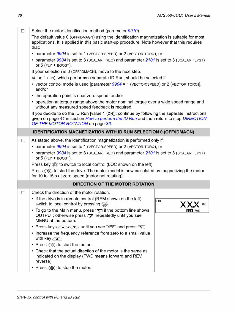
DIRECTION OF THE MOTOR ROTATION
Check the direction of the motor rotation.• If the drive is in remote control (REM shown on the left),
switch to local control by pressing . • To go to the Main menu, press if the bottom line shows
OUTPUT; otherwise press repeatedly until you see MENU at the bottom.
• Press keys / until you see “rEF” and press .• Increase the frequency reference from zero to a small value
with key . • Press to start the motor.• Check that the actual direction of the motor is the same as
indicated on the display (FWD means forward and REV reverse).
• Press to stop the motor.
LOCREM
LOCREM
LOC Hz
SET FWD
xxx.
Start-up, control with I/O and ID Run
ACS550-01/U1 User’s Manual 37
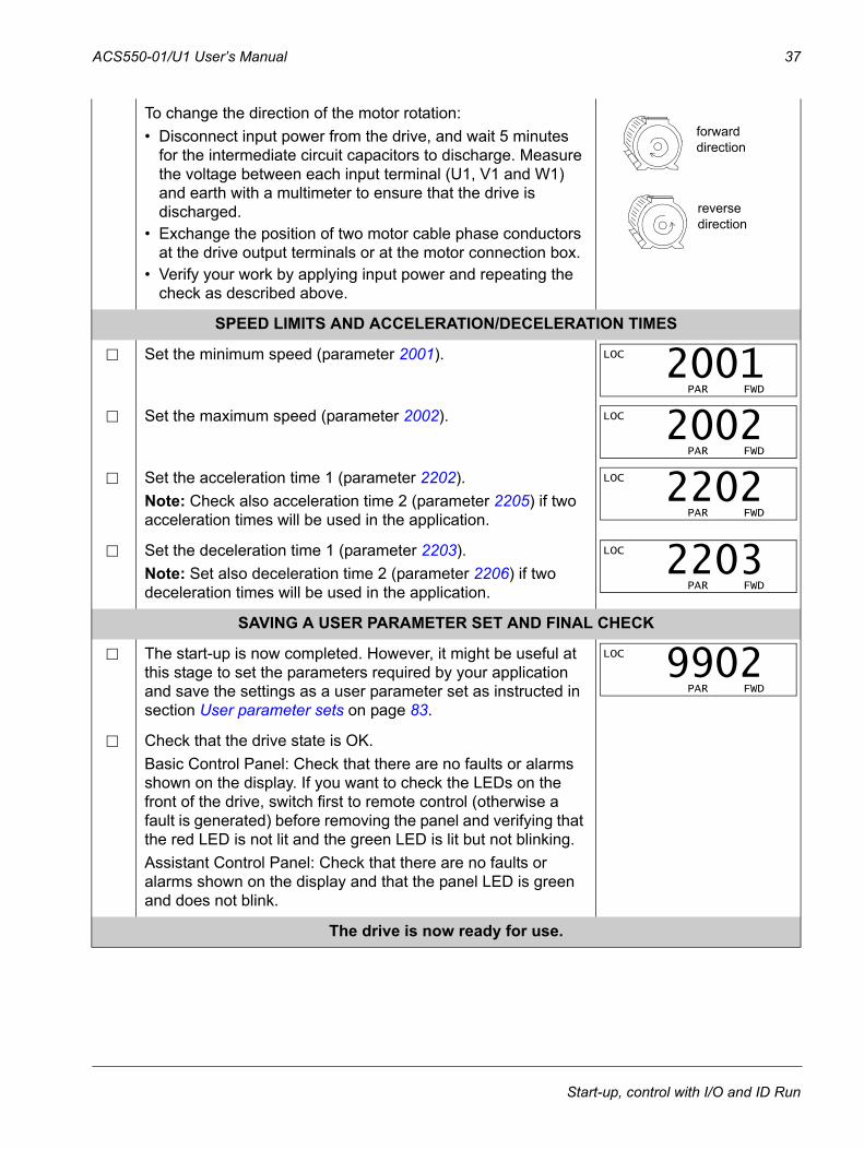
To change the direction of the motor rotation:• Disconnect input power from the drive, and wait 5 minutes
for the intermediate circuit capacitors to discharge. Measure the voltage between each input terminal (U1, V1 and W1) and earth with a multimeter to ensure that the drive is discharged.
• Exchange the position of two motor cable phase conductors at the drive output terminals or at the motor connection box.
• Verify your work by applying input power and repeating the check as described above.
SPEED LIMITS AND ACCELERATION/DECELERATION TIMES
Set the minimum speed (parameter 2001).
Set the maximum speed (parameter 2002).
Set the acceleration time 1 (parameter 2202).Note: Check also acceleration time 2 (parameter 2205) if two acceleration times will be used in the application.
Set the deceleration time 1 (parameter 2203).Note: Set also deceleration time 2 (parameter 2206) if two deceleration times will be used in the application.
SAVING A USER PARAMETER SET AND FINAL CHECK
The start-up is now completed. However, it might be useful at this stage to set the parameters required by your application and save the settings as a user parameter set as instructed in section User parameter sets on page 83.
Check that the drive state is OK.Basic Control Panel: Check that there are no faults or alarms shown on the display. If you want to check the LEDs on the front of the drive, switch first to remote control (otherwise a fault is generated) before removing the panel and verifying that the red LED is not lit and the green LED is lit but not blinking.Assistant Control Panel: Check that there are no faults or alarms shown on the display and that the panel LED is green and does not blink.
The drive is now ready for use.
forward direction
reverse direction
LOC
PAR FWD
2001 LOC
PAR FWD
2002 LOC
PAR FWD
2202
LOC
PAR FWD
2203
LOC
PAR FWD
9902
Start-up, control with I/O and ID Run
38 ACS550-01/U1 User’s Manual
How to perform the guided start-up To be able to perform the guided start-up, you need the Assistant Control Panel.
Before you start, ensure that you have the motor nameplate data on hand.
SAFETY
The start-up may only be carried out by a qualified electrician.The safety instructions given in chapter Safety must be followed during the start-up procedure.
The drive will start up automatically at power up, if the external run command is on.
Check the installation. See the checklist in chapter Installation, page 31.
Check that the starting of the motor does not cause any danger. De-couple the driven machine if:• there is a risk of damage in case of incorrect direction of rotation, or • an ID Run needs to be performed during the drive start-up. ID Run is essential only in
applications that require the ultimate in motor control accuracy.
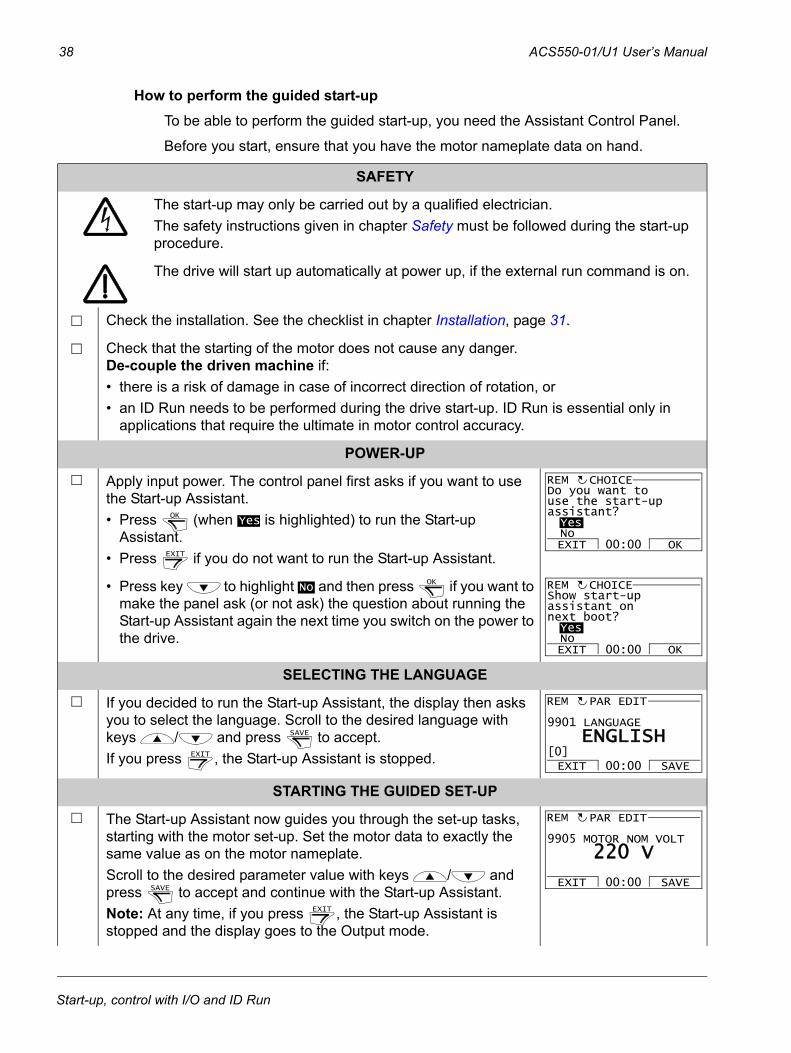
POWER-UP
Apply input power. The control panel first asks if you want to use the Start-up Assistant. • Press (when is highlighted) to run the Start-up
Assistant.• Press if you do not want to run the Start-up Assistant.
• Press key to highlight and then press if you want to make the panel ask (or not ask) the question about running the Start-up Assistant again the next time you switch on the power to the drive.
SELECTING THE LANGUAGE
If you decided to run the Start-up Assistant, the display then asks you to select the language. Scroll to the desired language with keys / and press to accept. If you press , the Start-up Assistant is stopped.
STARTING THE GUIDED SET-UP
The Start-up Assistant now guides you through the set-up tasks, starting with the motor set-up. Set the motor data to exactly the same value as on the motor nameplate.Scroll to the desired parameter value with keys / and press to accept and continue with the Start-up Assistant. Note: At any time, if you press , the Start-up Assistant is stopped and the display goes to the Output mode.
OKYes
EXIT
Do you want touse the start-upassistant?YesNoEXIT OK00:00
CHOICEREM
NoOK
Show start-upassistant onnext boot?YesNoEXIT OK00:00
CHOICEREM
SAVE
EXIT
9901 LANGUAGE
PAR EDIT
ENGLISH
EXIT SAVE00:00[0]
REM
SAVE
EXIT
9905 MOTOR NOM VOLT
PAR EDIT
220 V
EXIT SAVE00:00
REM
Start-up, control with I/O and ID Run
ACS550-01/U1 User’s Manual 39
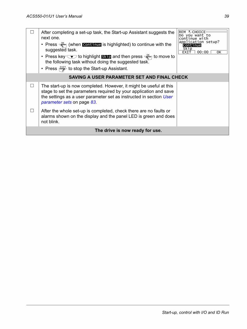
After completing a set-up task, the Start-up Assistant suggests the next one. • Press (when is highlighted) to continue with the
suggested task.• Press key to highlight and then press to move to
the following task without doing the suggested task. • Press to stop the Start-up Assistant.
SAVING A USER PARAMETER SET AND FINAL CHECK
The start-up is now completed. However, it might be useful at this stage to set the parameters required by your application and save the settings as a user parameter set as instructed in section User parameter sets on page 83.
After the whole set-up is completed, check there are no faults or alarms shown on the display and the panel LED is green and does not blink.
The drive is now ready for use.
OKContinue
SkipOK
EXIT
Do you want tocontinue withapplication setup?ContinueSkipEXIT OK00:00
CHOICEREM
Start-up, control with I/O and ID Run
40 ACS550-01/U1 User’s Manual
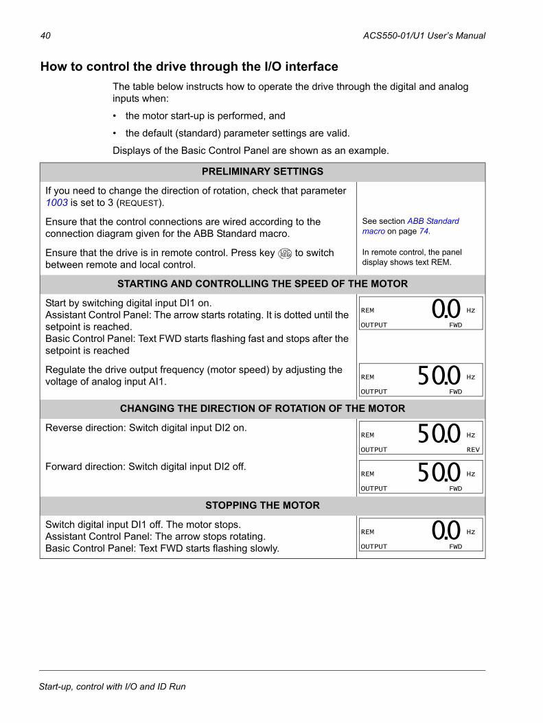
How to control the drive through the I/O interfaceThe table below instructs how to operate the drive through the digital and analog inputs when:
• the motor start-up is performed, and
• the default (standard) parameter settings are valid.
Displays of the Basic Control Panel are shown as an example.
PRELIMINARY SETTINGS
If you need to change the direction of rotation, check that parameter 1003 is set to 3 (REQUEST).
Ensure that the control connections are wired according to the connection diagram given for the ABB Standard macro.
See section ABB Standard macro on page 74.
Ensure that the drive is in remote control. Press key to switch between remote and local control.
In remote control, the panel display shows text REM.
STARTING AND CONTROLLING THE SPEED OF THE MOTOR
Start by switching digital input DI1 on. Assistant Control Panel: The arrow starts rotating. It is dotted until the setpoint is reached.Basic Control Panel: Text FWD starts flashing fast and stops after the setpoint is reached
Regulate the drive output frequency (motor speed) by adjusting the voltage of analog input AI1.
CHANGING THE DIRECTION OF ROTATION OF THE MOTOR
Reverse direction: Switch digital input DI2 on.
Forward direction: Switch digital input DI2 off.
STOPPING THE MOTOR
Switch digital input DI1 off. The motor stops.Assistant Control Panel: The arrow stops rotating.Basic Control Panel: Text FWD starts flashing slowly.
LOCREM
REM Hz
OUTPUT FWD
00.
REM Hz
OUTPUT FWD
500.
REM Hz
OUTPUT REV
500. REM Hz
OUTPUT FWD
500.
REM Hz
OUTPUT FWD
00.
Start-up, control with I/O and ID Run
ACS550-01/U1 User’s Manual 41
How to perform the ID RunThe drive estimates motor characteristics automatically using identification magnetization when the drive is started for the first time and after any motor parameter (Group 99: START-UP DATA) is changed. This is valid when parameter 9910 ID RUN has value 0 (OFF/IDMAGN), and
• parameter 9904 = 1 (VECTOR:SPEED) or 2 (VECTOR:TORQ), or
• parameter 9904 = 3 (SCALAR:FREQ) and parameter 2101 = 3 (SCALAR FLYST) or 5 (FLY + BOOST).
In most applications there is no need to perform a separate ID Run [9910 ID RUN = 1 (ON)]. The ID Run should be selected if:
• vector control mode is used [parameter 9904 = 1 (VECTOR:SPEED) or 2 (VECTOR:TORQ)], and/or
• the operation point is near zero speed, and/or
• operation at torque range above the motor nominal torque over a wide speed range and without any measured speed feedback is required.
Note: If motor parameters (Group 99: START-UP DATA) are changed after the ID Run, it must be repeated.
ID Run procedureThe general parameter setting procedure is not repeated here. For Assistant Control Panel see page 51 and for Basic Control Panel page 69 in chapter Control panels.
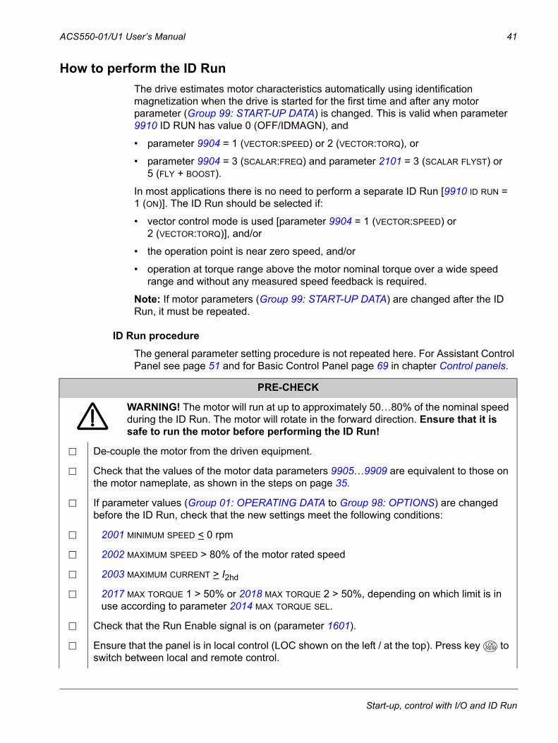
PRE-CHECK
WARNING! The motor will run at up to approximately 50…80% of the nominal speed during the ID Run. The motor will rotate in the forward direction. Ensure that it is safe to run the motor before performing the ID Run!
De-couple the motor from the driven equipment.
Check that the values of the motor data parameters 9905…9909 are equivalent to those on the motor nameplate, as shown in the steps on page 35.
If parameter values (Group 01: OPERATING DATA to Group 98: OPTIONS) are changed before the ID Run, check that the new settings meet the following conditions:
2001 MINIMUM SPEED < 0 rpm
2002 MAXIMUM SPEED > 80% of the motor rated speed
2003 MAXIMUM CURRENT > I2hd
2017 MAX TORQUE 1 > 50% or 2018 MAX TORQUE 2 > 50%, depending on which limit is in use according to parameter 2014 MAX TORQUE SEL.
Check that the Run Enable signal is on (parameter 1601).
Ensure that the panel is in local control (LOC shown on the left / at the top). Press key to switch between local and remote control.
LOCREM
Start-up, control with I/O and ID Run
42 ACS550-01/U1 User’s Manual
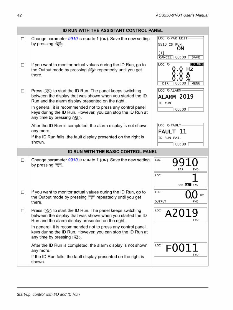
ID RUN WITH THE ASSISTANT CONTROL PANEL
Change parameter 9910 ID RUN to 1 (ON). Save the new setting by pressing .
If you want to monitor actual values during the ID Run, go to the Output mode by pressing repeatedly until you get there.
Press to start the ID Run. The panel keeps switching between the display that was shown when you started the ID Run and the alarm display presented on the right.In general, it is recommended not to press any control panel keys during the ID Run. However, you can stop the ID Run at any time by pressing .
After the ID Run is completed, the alarm display is not shown any more.If the ID Run fails, the fault display presented on the right is shown.
ID RUN WITH THE BASIC CONTROL PANEL
Change parameter 9910 ID RUN to 1 (ON). Save the new setting by pressing .
If you want to monitor actual values during the ID Run, go to the Output mode by pressing repeatedly until you get there.
Press to start the ID Run. The panel keeps switching between the display that was shown when you started the ID Run and the alarm display presented on the right.In general, it is recommended not to press any control panel keys during the ID Run. However, you can stop the ID Run at any time by pressing .
After the ID Run is completed, the alarm display is not shown any more. If the ID Run fails, the fault display presented on the right is shown.
SAVE
9910 ID RUN
PAR EDIT
ON
CANCEL SAVE00:00[1]
LOC
EXIT
0 A0 Hz
0 % 0.0.0.
50.0HzLOC
DIR MENU00:00
00:00
ID run
ALARMLOC
ALARM 2019
00:00
ID RUN FAIL
FAULTLOC
FAULT 11
LOC
PAR FWD
9910 LOC
PAR SET FWD
1 LOC Hz
OUTPUT FWD
00.LOC
FWD
A2019
LOC
FWD
F0011
Start-up, control with I/O and ID Run
ACS550-01/U1 User’s Manual 43
Control panels
About control panelsUse a control panel to control the drive, read status data and adjust parameters. The drive works with either of two different control panel types:
• Basic Control Panel – This panel (described in section Basic Control Panel on page 64) provides basic tools for manual entry of parameter values.
• Assistant Control Panel – This panel (described below) includes pre-programmed assistants to automate the most common parameter setups. The panel provides language support. It is available with different language sets.
CompatibilityThe manual is compatible with the following panel versions:
• Basic Control Panel: ACS-CP-C Rev. M or later
• Assistant Control Panel (Area 1): ACS-CP-A Rev. F or later(new panel series manufactured since 2007 with serial number XYYWWRXXXX, where year YY = 07 or greater and revision R = F, G, E, …)
• Assistant Control Panel (Asia): ACS-CP-D Rev. Q or later
See page 47 for how to find out the version of your Assistant Control Panel. See parameter 9901 LANGUAGE to see the languages supported by the different Assistant Control Panels.
Control panels
44 ACS550-01/U1 User’s Manual
Assistant Control Panel
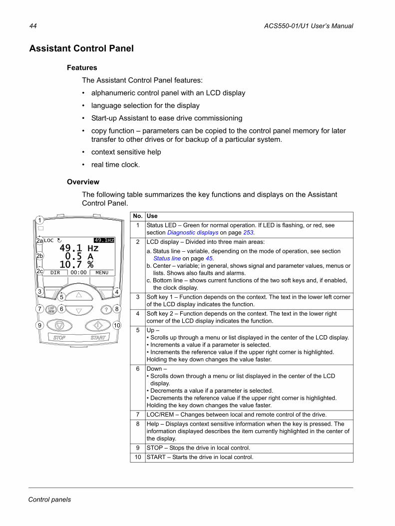
FeaturesThe Assistant Control Panel features:
• alphanumeric control panel with an LCD display
• language selection for the display
• Start-up Assistant to ease drive commissioning
• copy function – parameters can be copied to the control panel memory for later transfer to other drives or for backup of a particular system.
• context sensitive help
• real time clock.
OverviewThe following table summarizes the key functions and displays on the Assistant Control Panel.
LOC
DIR 12:45 MENU
400RPM
1200 RPM12.4 A
405 dm3/s
3 45
67 8
9 10
No. Use1 Status LED – Green for normal operation. If LED is flashing, or red, see
section Diagnostic displays on page 253.2 LCD display – Divided into three main areas:
a. Status line – variable, depending on the mode of operation, see section Status line on page 45.
b. Center – variable; in general, shows signal and parameter values, menus or lists. Shows also faults and alarms.
c. Bottom line – shows current functions of the two soft keys and, if enabled, the clock display.
3 Soft key 1 – Function depends on the context. The text in the lower left corner of the LCD display indicates the function.
4 Soft key 2 – Function depends on the context. The text in the lower right corner of the LCD display indicates the function.
5 Up – • Scrolls up through a menu or list displayed in the center of the LCD display. • Increments a value if a parameter is selected.• Increments the reference value if the upper right corner is highlighted.Holding the key down changes the value faster.
6 Down – • Scrolls down through a menu or list displayed in the center of the LCD
display. • Decrements a value if a parameter is selected.• Decrements the reference value if the upper right corner is highlighted.Holding the key down changes the value faster.
7 LOC/REM – Changes between local and remote control of the drive.8 Help – Displays context sensitive information when the key is pressed. The
information displayed describes the item currently highlighted in the center of the display.
9 STOP – Stops the drive in local control.10 START – Starts the drive in local control.
5 A1 Hz
7 %10.0.
49.49.1HzLOC
DIR MENU00:00
1
2a
2b
2c
Control panels
ACS550-01/U1 User’s Manual 45
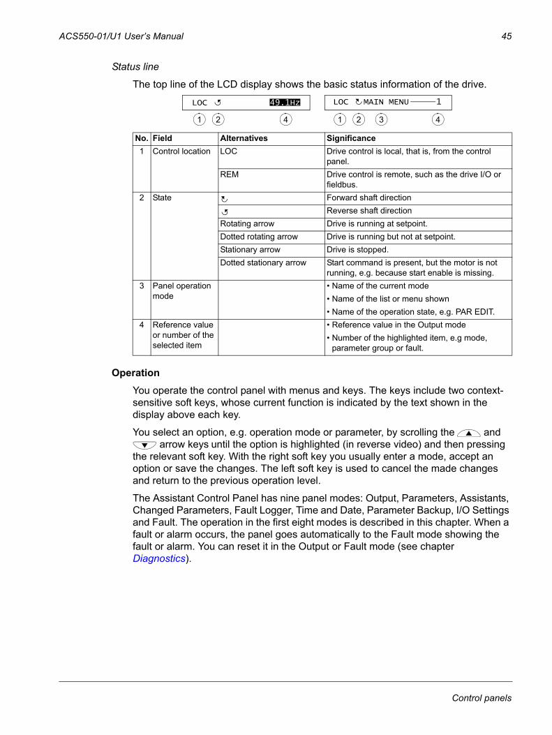
Status line
The top line of the LCD display shows the basic status information of the drive.
OperationYou operate the control panel with menus and keys. The keys include two context-sensitive soft keys, whose current function is indicated by the text shown in the display above each key.
You select an option, e.g. operation mode or parameter, by scrolling the and arrow keys until the option is highlighted (in reverse video) and then pressing
the relevant soft key. With the right soft key you usually enter a mode, accept an option or save the changes. The left soft key is used to cancel the made changes and return to the previous operation level.
The Assistant Control Panel has nine panel modes: Output, Parameters, Assistants, Changed Parameters, Fault Logger, Time and Date, Parameter Backup, I/O Settings and Fault. The operation in the first eight modes is described in this chapter. When a fault or alarm occurs, the panel goes automatically to the Fault mode showing the fault or alarm. You can reset it in the Output or Fault mode (see chapter Diagnostics).
No. Field Alternatives Significance1 Control location LOC Drive control is local, that is, from the control
panel.REM Drive control is remote, such as the drive I/O or
fieldbus.2 State Forward shaft direction
Reverse shaft directionRotating arrow Drive is running at setpoint.Dotted rotating arrow Drive is running but not at setpoint.Stationary arrow Drive is stopped.Dotted stationary arrow Start command is present, but the motor is not
running, e.g. because start enable is missing.3 Panel operation
mode• Name of the current mode• Name of the list or menu shown• Name of the operation state, e.g. PAR EDIT.
4 Reference value or number of the selected item
• Reference value in the Output mode• Number of the highlighted item, e.g mode,
parameter group or fault.
49.1HzLOC
1 2 4
LOC MAIN MENU 1
1 2 3 4
Control panels
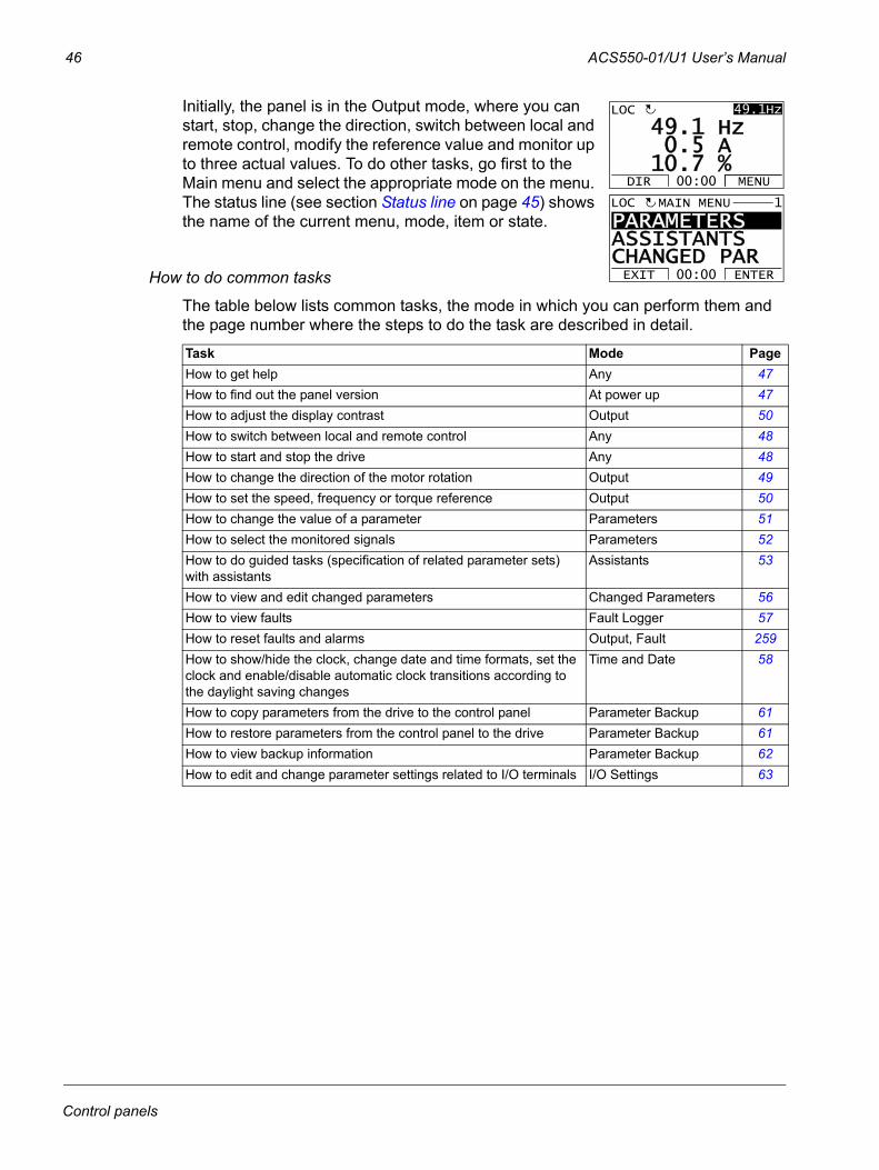
46 ACS550-01/U1 User’s Manual
Initially, the panel is in the Output mode, where you can start, stop, change the direction, switch between local and remote control, modify the reference value and monitor up to three actual values. To do other tasks, go first to the Main menu and select the appropriate mode on the menu. The status line (see section Status line on page 45) shows the name of the current menu, mode, item or state.
How to do common tasks
The table below lists common tasks, the mode in which you can perform them and the page number where the steps to do the task are described in detail.
Task Mode PageHow to get help Any 47How to find out the panel version At power up 47How to adjust the display contrast Output 50How to switch between local and remote control Any 48How to start and stop the drive Any 48How to change the direction of the motor rotation Output 49How to set the speed, frequency or torque reference Output 50How to change the value of a parameter Parameters 51How to select the monitored signals Parameters 52How to do guided tasks (specification of related parameter sets) with assistants
Assistants 53
How to view and edit changed parameters Changed Parameters 56How to view faults Fault Logger 57How to reset faults and alarms Output, Fault 259How to show/hide the clock, change date and time formats, set the clock and enable/disable automatic clock transitions according to the daylight saving changes
Time and Date 58
How to copy parameters from the drive to the control panel Parameter Backup 61How to restore parameters from the control panel to the drive Parameter Backup 61How to view backup information Parameter Backup 62How to edit and change parameter settings related to I/O terminals I/O Settings 63
PARAMETERS ASSISTANTSCHANGED PAREXIT ENTER00:00
MAIN MENU 1LOC
5 A1 Hz
7 %10.0.
49.49.1HzLOC
DIR MENU00:00
Control panels
ACS550-01/U1 User’s Manual 47
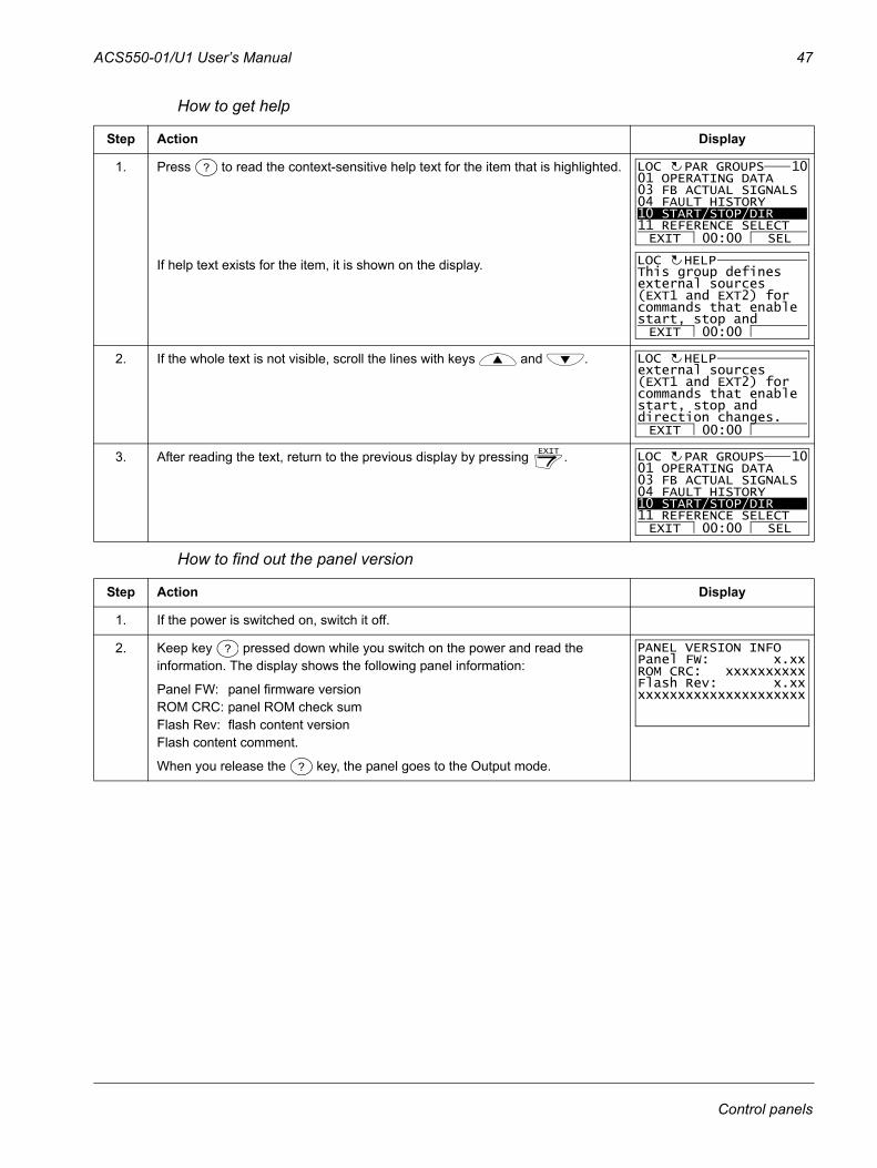
How to get help
How to find out the panel version
Step Action Display
1. Press to read the context-sensitive help text for the item that is highlighted.
If help text exists for the item, it is shown on the display.
2. If the whole text is not visible, scroll the lines with keys and .
3. After reading the text, return to the previous display by pressing .
Step Action Display
1. If the power is switched on, switch it off.
2. Keep key pressed down while you switch on the power and read the information. The display shows the following panel information:
Panel FW: panel firmware versionROM CRC: panel ROM check sumFlash Rev: flash content versionFlash content comment.
When you release the key, the panel goes to the Output mode.
? 01 OPERATING DATA03 FB ACTUAL SIGNALS04 FAULT HISTORY10 START/STOP/DIR11 REFERENCE SELECT
PAR GROUPS 10
EXIT SEL00:00
LOC
EXIT 00:00
This group definesexternal sources(EXT1 and EXT2) forcommands that enablestart, stop and
HELPLOC
EXIT 00:00
external sources(EXT1 and EXT2) forcommands that enablestart, stop anddirection changes.
HELPLOC
EXIT 01 OPERATING DATA03 FB ACTUAL SIGNALS04 FAULT HISTORY10 START/STOP/DIR11 REFERENCE SELECT
PAR GROUPS 10
EXIT SEL00:00
LOC
?
?
Panel FW: x.xxROM CRC: xxxxxxxxxxFlash Rev: x.xxxxxxxxxxxxxxxxxxxxxxx
PANEL VERSION INFO
Control panels
48 ACS550-01/U1 User’s Manual
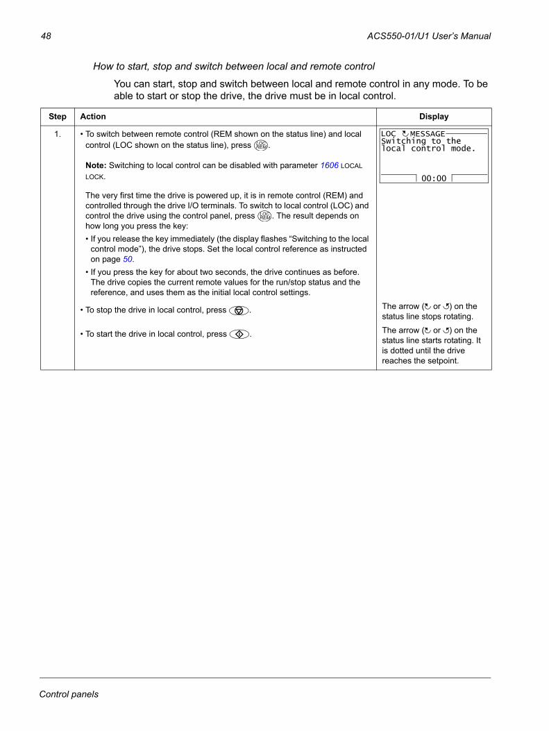
How to start, stop and switch between local and remote control
You can start, stop and switch between local and remote control in any mode. To be able to start or stop the drive, the drive must be in local control.
Step Action Display
1. • To switch between remote control (REM shown on the status line) and local control (LOC shown on the status line), press .
Note: Switching to local control can be disabled with parameter 1606 LOCAL LOCK.
The very first time the drive is powered up, it is in remote control (REM) and controlled through the drive I/O terminals. To switch to local control (LOC) and control the drive using the control panel, press . The result depends on how long you press the key:• If you release the key immediately (the display flashes “Switching to the local
control mode”), the drive stops. Set the local control reference as instructed on page 50.
• If you press the key for about two seconds, the drive continues as before. The drive copies the current remote values for the run/stop status and the reference, and uses them as the initial local control settings.
• To stop the drive in local control, press . The arrow ( or ) on the status line stops rotating.
• To start the drive in local control, press . The arrow ( or ) on the status line starts rotating. It is dotted until the drive reaches the setpoint.
LOCREM
00:00
Switching to thelocal control mode.
MESSAGELOC
LOCREM
Control panels
ACS550-01/U1 User’s Manual 49
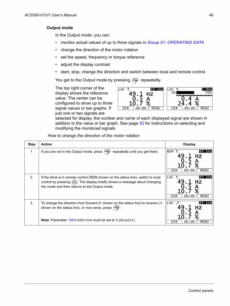
Output modeIn the Output mode, you can:
• monitor actual values of up to three signals in Group 01: OPERATING DATA
• change the direction of the motor rotation
• set the speed, frequency or torque reference
• adjust the display contrast
• start, stop, change the direction and switch between local and remote control.
You get to the Output mode by pressing repeatedly.
The top right corner of the display shows the reference value. The center can be configured to show up to three signal values or bar graphs. If just one or two signals are selected for display, the number and name of each displayed signal are shown in addition to the value or bar graph. See page 52 for instructions on selecting and modifying the monitored signals.
How to change the direction of the motor rotation
Step Action Display
1. If you are not in the Output mode, press repeatedly until you get there.
2. If the drive is in remote control (REM shown on the status line), switch to local control by pressing . The display briefly shows a message about changing the mode and then returns to the Output mode.
3. To change the direction from forward ( shown on the status line) to reverse ( shown on the status line), or vice versa, press .
Note: Parameter 1003 DIRECTION must be set to 3 (REQUEST).
EXIT
5 A1 Hz
7 %10.0.
49.49.1HzLOC
DIR MENU00:00
4 A
4 %24.0.
5.0HzLOC
DIR MENU00:00
HZ 50%
EXIT
5 A1 Hz
7 %10.0.
49.49.1HzREM
DIR MENU00:00
LOCREM
5 A1 Hz
7 %10.0.
49.49.1HzLOC
DIR MENU00:00
DIR
5 A1 Hz
7 %10.0.
49.49.1HzLOC
DIR MENU00:00
Control panels
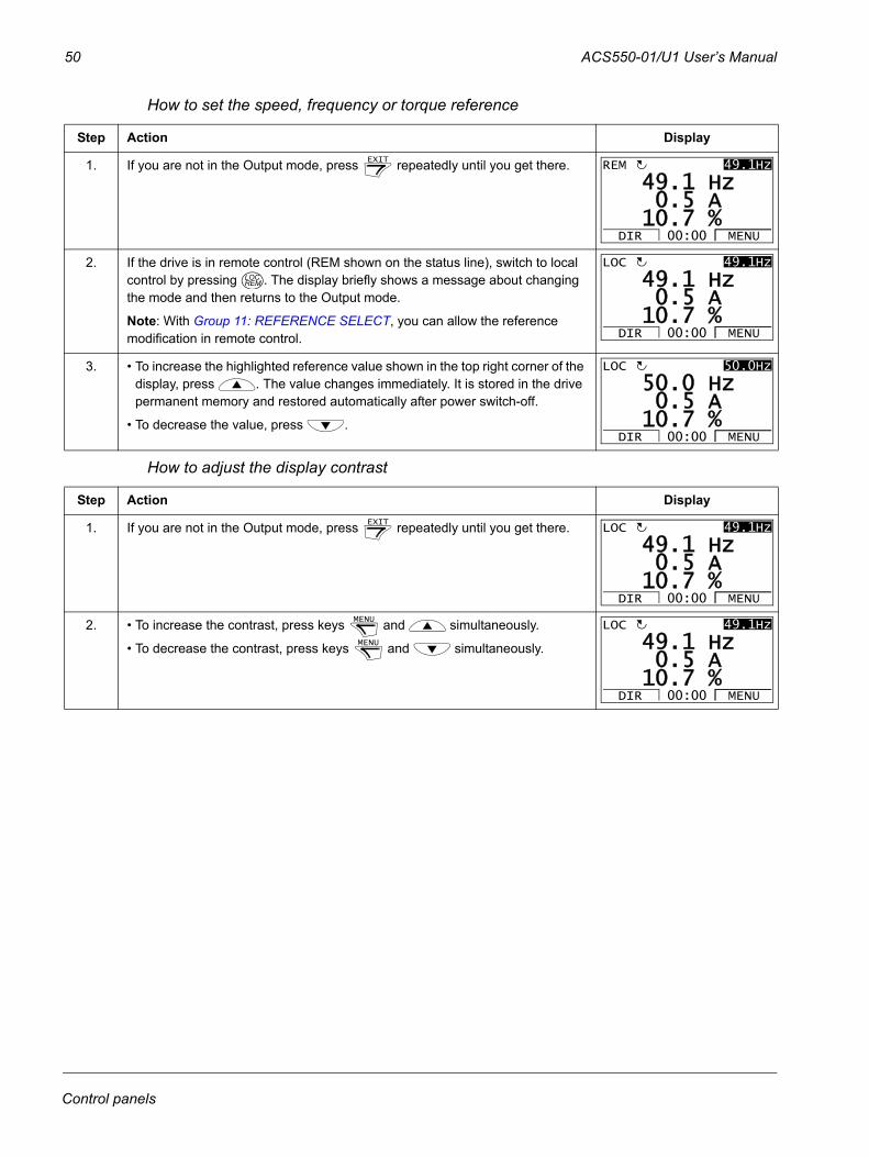
50 ACS550-01/U1 User’s Manual
How to set the speed, frequency or torque reference
How to adjust the display contrast
Step Action Display
1. If you are not in the Output mode, press repeatedly until you get there.
2. If the drive is in remote control (REM shown on the status line), switch to local control by pressing . The display briefly shows a message about changing the mode and then returns to the Output mode.
Note: With Group 11: REFERENCE SELECT, you can allow the reference modification in remote control.
3. • To increase the highlighted reference value shown in the top right corner of the display, press . The value changes immediately. It is stored in the drive permanent memory and restored automatically after power switch-off.
• To decrease the value, press .
Step Action Display
1. If you are not in the Output mode, press repeatedly until you get there.
2. • To increase the contrast, press keys and simultaneously.
• To decrease the contrast, press keys and simultaneously.
EXIT
5 A1 Hz
7 %10.0.
49.49.1HzREM
DIR MENU00:00
LOCREM
5 A1 Hz
7 %10.0.
49.49.1HzLOC
DIR MENU00:00
5 A0 Hz
7 %10.0.
50.50.0HzLOC
DIR MENU00:00
EXIT
5 A1 Hz
7 %10.0.
49.49.1HzLOC
DIR MENU00:00
MENU
MENU
5 A1 Hz
7 %10.0.
49.49.1HzLOC
DIR MENU00:00
Control panels
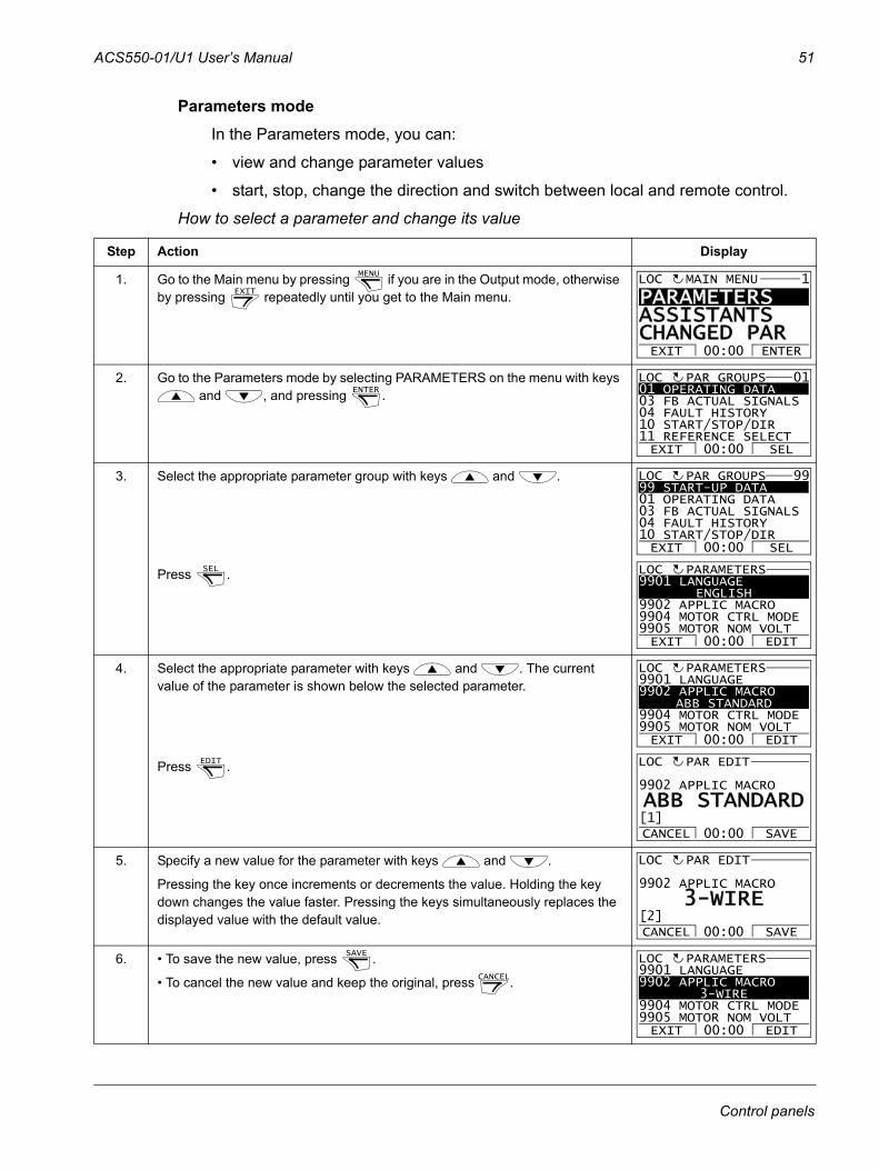
ACS550-01/U1 User’s Manual 51
Parameters modeIn the Parameters mode, you can:
• view and change parameter values
• start, stop, change the direction and switch between local and remote control.
How to select a parameter and change its value
Step Action Display
1. Go to the Main menu by pressing if you are in the Output mode, otherwise by pressing repeatedly until you get to the Main menu.
2. Go to the Parameters mode by selecting PARAMETERS on the menu with keys and , and pressing .
3. Select the appropriate parameter group with keys and .
Press .
4. Select the appropriate parameter with keys and . The current value of the parameter is shown below the selected parameter.
Press .
5. Specify a new value for the parameter with keys and .
Pressing the key once increments or decrements the value. Holding the key down changes the value faster. Pressing the keys simultaneously replaces the displayed value with the default value.
6. • To save the new value, press .
• To cancel the new value and keep the original, press .
MENU
EXIT
PARAMETERS ASSISTANTSCHANGED PAREXIT ENTER00:00
MAIN MENU 1LOC
ENTER 01 OPERATING DATA03 FB ACTUAL SIGNALS04 FAULT HISTORY10 START/STOP/DIR11 REFERENCE SELECTEXIT SEL00:00
PAR GROUPS 01LOC
99 START-UP DATA01 OPERATING DATA03 FB ACTUAL SIGNALS04 FAULT HISTORY10 START/STOP/DIREXIT SEL00:00
PAR GROUPS 99LOC
SEL 9901 LANGUAGE
ENGLISH9902 APPLIC MACRO9904 MOTOR CTRL MODE9905 MOTOR NOM VOLT
PARAMETERS
EXIT EDIT00:00
LOC
9901 LANGUAGE9902 APPLIC MACRO
ABB STANDARD9904 MOTOR CTRL MODE9905 MOTOR NOM VOLT
PARAMETERS
EXIT EDIT00:00
LOC
EDIT 9902 APPLIC MACRO
PAR EDIT
ABB STANDARD
CANCEL SAVE00:00[1]
LOC
9902 APPLIC MACRO
PAR EDIT
3-WIRE
CANCEL SAVE00:00[2]
LOC
SAVE
CANCEL
9901 LANGUAGE9902 APPLIC MACRO
3-WIRE9904 MOTOR CTRL MODE9905 MOTOR NOM VOLT
PARAMETERS
EXIT EDIT00:00
LOC
Control panels
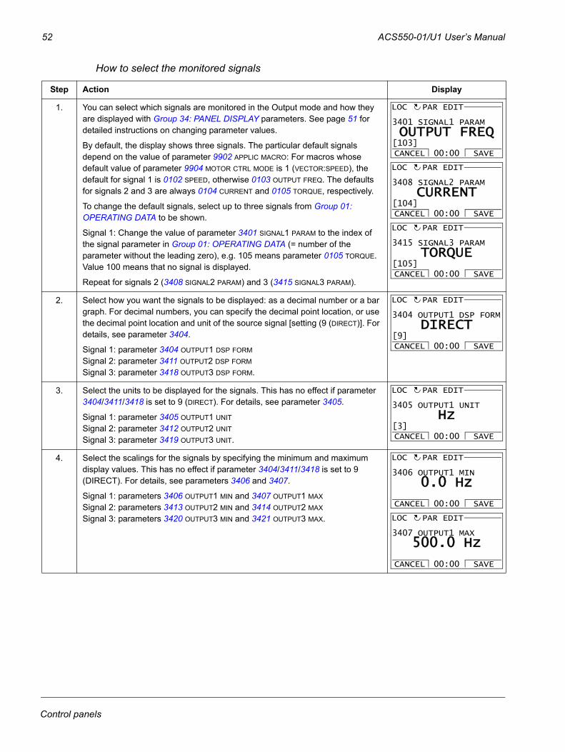
52 ACS550-01/U1 User’s Manual
How to select the monitored signals
Step Action Display
1. You can select which signals are monitored in the Output mode and how they are displayed with Group 34: PANEL DISPLAY parameters. See page 51 for detailed instructions on changing parameter values.
By default, the display shows three signals. The particular default signals depend on the value of parameter 9902 APPLIC MACRO: For macros whose default value of parameter 9904 MOTOR CTRL MODE is 1 (VECTOR:SPEED), the default for signal 1 is 0102 SPEED, otherwise 0103 OUTPUT FREQ. The defaults for signals 2 and 3 are always 0104 CURRENT and 0105 TORQUE, respectively.
To change the default signals, select up to three signals from Group 01: OPERATING DATA to be shown.
Signal 1: Change the value of parameter 3401 SIGNAL1 PARAM to the index of the signal parameter in Group 01: OPERATING DATA (= number of the parameter without the leading zero), e.g. 105 means parameter 0105 TORQUE. Value 100 means that no signal is displayed.
Repeat for signals 2 (3408 SIGNAL2 PARAM) and 3 (3415 SIGNAL3 PARAM).
2. Select how you want the signals to be displayed: as a decimal number or a bar graph. For decimal numbers, you can specify the decimal point location, or use the decimal point location and unit of the source signal [setting (9 (DIRECT)]. For details, see parameter 3404.
Signal 1: parameter 3404 OUTPUT1 DSP FORM
Signal 2: parameter 3411 OUTPUT2 DSP FORM
Signal 3: parameter 3418 OUTPUT3 DSP FORM.
3. Select the units to be displayed for the signals. This has no effect if parameter 3404/3411/3418 is set to 9 (DIRECT). For details, see parameter 3405.
Signal 1: parameter 3405 OUTPUT1 UNIT
Signal 2: parameter 3412 OUTPUT2 UNIT
Signal 3: parameter 3419 OUTPUT3 UNIT.
4. Select the scalings for the signals by specifying the minimum and maximum display values. This has no effect if parameter 3404/3411/3418 is set to 9 (DIRECT). For details, see parameters 3406 and 3407.
Signal 1: parameters 3406 OUTPUT1 MIN and 3407 OUTPUT1 MAX
Signal 2: parameters 3413 OUTPUT2 MIN and 3414 OUTPUT2 MAX
Signal 3: parameters 3420 OUTPUT3 MIN and 3421 OUTPUT3 MAX.
3401 SIGNAL1 PARAM
PAR EDIT
OUTPUT FREQ
CANCEL SAVE00:00[103]
LOC
3408 SIGNAL2 PARAM
PAR EDIT
CURRENT
CANCEL SAVE00:00[104]
LOC
3415 SIGNAL3 PARAM
PAR EDIT
TORQUE
CANCEL SAVE00:00[105]
LOC
3404 OUTPUT1 DSP FORM
PAR EDIT
DIRECT
CANCEL SAVE00:00[9]
LOC
3405 OUTPUT1 UNIT
PAR EDIT
Hz
CANCEL SAVE00:00[3]
LOC
3406 OUTPUT1 MIN
PAR EDIT
0.0 Hz
CANCEL SAVE00:00
LOC
3407 OUTPUT1 MAX
PAR EDIT
500.0 Hz
CANCEL SAVE00:00
LOC
Control panels
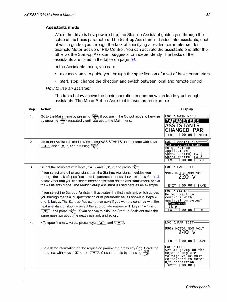
ACS550-01/U1 User’s Manual 53
Assistants modeWhen the drive is first powered up, the Start-up Assistant guides you through the setup of the basic parameters. The Start-up Assistant is divided into assistants, each of which guides you through the task of specifying a related parameter set, for example Motor Set-up or PID Control. You can activate the assistants one after the other as the Start-up Assistant suggests, or independently. The tasks of the assistants are listed in the table on page 54.
In the Assistants mode, you can:
• use assistants to guide you through the specification of a set of basic parameters
• start, stop, change the direction and switch between local and remote control.
How to use an assistant
The table below shows the basic operation sequence which leads you through assistants. The Motor Set-up Assistant is used as an example.
Step Action Display
1. Go to the Main menu by pressing if you are in the Output mode, otherwise by pressing repeatedly until you get to the Main menu.
2. Go to the Assistants mode by selecting ASSISTANTS on the menu with keys and , and pressing .
3. Select the assistant with keys and , and press .If you select any other assistant than the Start-up Assistant, it guides you through the task of specification of its parameter set as shown in steps 4. and 5. below. After that you can select another assistant on the Assistants menu or exit the Assistants mode. The Motor Set-up Assistant is used here as an example.
If you select the Start-up Assistant, it activates the first assistant, which guides you through the task of specification of its parameter set as shown in steps 4. and 5. below. The Start-up Assistant then asks if you want to continue with the next assistant or skip it – select the appropriate answer with keys and
, and press . If you choose to skip, the Start-up Assistant asks the same question about the next assistant, and so on.
4. • To specify a new value, press keys and .
• To ask for information on the requested parameter, press key . Scroll the help text with keys and . Close the help by pressing .
MENU
EXIT
PARAMETERS ASSISTANTSCHANGED PAREXIT ENTER00:00
MAIN MENU 1LOC
ENTER Start-up assistantMotor Set-upApplicationSpeed control EXT1Speed control EXT2EXIT SEL00:00
ASSISTANTS 1LOC
SEL 9905 MOTOR NOM VOLT
PAR EDIT
220 V
EXIT SAVE00:00
LOC
SEL
Do you want tocontinue withapplication setup?ContinueSkipEXIT OK00:00
CHOICELOC
9905 MOTOR NOM VOLT
PAR EDIT
240 V
EXIT SAVE00:00
LOC
?EXIT
EXIT 00:00
Set as given on themotor nameplate.Voltage value mustcorrespond to motorD/Y connection.
HELPLOC
Control panels
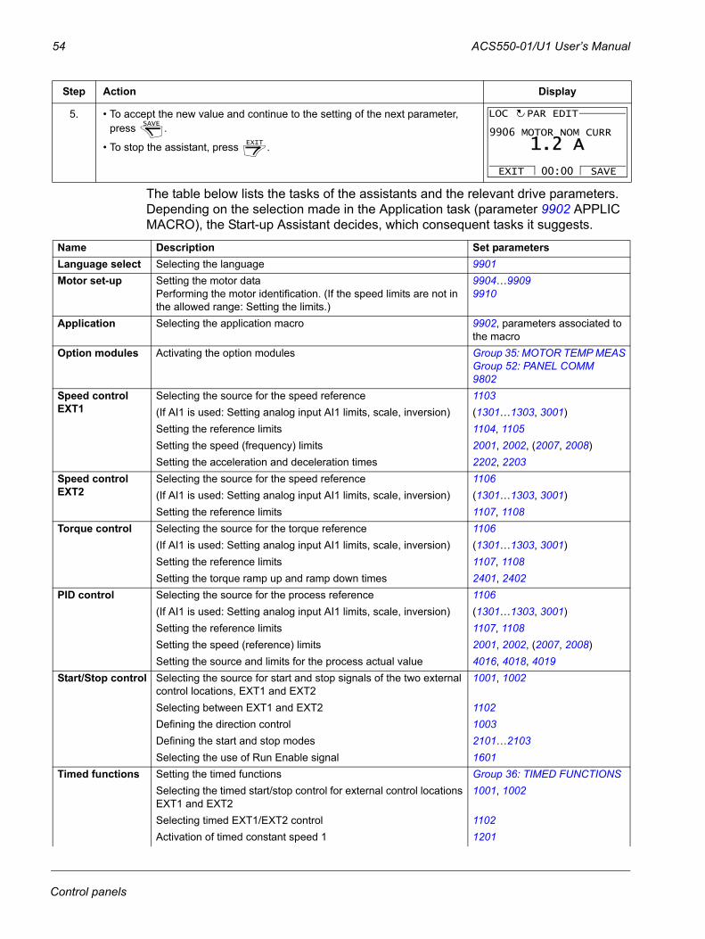
54 ACS550-01/U1 User’s Manual
The table below lists the tasks of the assistants and the relevant drive parameters. Depending on the selection made in the Application task (parameter 9902 APPLIC MACRO), the Start-up Assistant decides, which consequent tasks it suggests.
5. • To accept the new value and continue to the setting of the next parameter, press .
• To stop the assistant, press .
Name Description Set parametersLanguage select Selecting the language 9901Motor set-up Setting the motor data
Performing the motor identification. (If the speed limits are not in the allowed range: Setting the limits.)
9904…99099910
Application Selecting the application macro 9902, parameters associated to the macro
Option modules Activating the option modules Group 35: MOTOR TEMP MEAS Group 52: PANEL COMM9802
Speed control EXT1
Selecting the source for the speed reference 1103(If AI1 is used: Setting analog input AI1 limits, scale, inversion) (1301…1303, 3001)Setting the reference limits 1104, 1105Setting the speed (frequency) limits 2001, 2002, (2007, 2008)Setting the acceleration and deceleration times 2202, 2203
Speed control EXT2
Selecting the source for the speed reference 1106(If AI1 is used: Setting analog input AI1 limits, scale, inversion) (1301…1303, 3001)Setting the reference limits 1107, 1108
Torque control Selecting the source for the torque reference 1106(If AI1 is used: Setting analog input AI1 limits, scale, inversion) (1301…1303, 3001)Setting the reference limits 1107, 1108 Setting the torque ramp up and ramp down times 2401, 2402
PID control Selecting the source for the process reference 1106(If AI1 is used: Setting analog input AI1 limits, scale, inversion) (1301…1303, 3001)Setting the reference limits 1107, 1108 Setting the speed (reference) limits 2001, 2002, (2007, 2008)Setting the source and limits for the process actual value 4016, 4018, 4019
Start/Stop control Selecting the source for start and stop signals of the two external control locations, EXT1 and EXT2
1001, 1002
Selecting between EXT1 and EXT2 1102Defining the direction control 1003Defining the start and stop modes 2101…2103Selecting the use of Run Enable signal 1601
Timed functions Setting the timed functions Group 36: TIMED FUNCTIONSSelecting the timed start/stop control for external control locations EXT1 and EXT2
1001, 1002
Selecting timed EXT1/EXT2 control 1102Activation of timed constant speed 1 1201
Step Action Display
SAVE
EXIT
9906 MOTOR NOM CURR
PAR EDIT
1.2 A
EXIT SAVE00:00
LOC
Control panels

ACS550-01/U1 User’s Manual 55
Selecting timed function status indicated through relay output RO 1401Selecting timed PID1 parameter set 1/2 control 4027
Protections Setting the current and torque limits 2003, 2017Output signals Selecting the signals indicated through relay output RO Group 14: RELAY OUTPUTS
Selecting the signals indicated through analog output AOSetting the minimum, maximum, scaling and inversion
Group 15: ANALOG OUTPUTS
Name Description Set parameters
Control panels
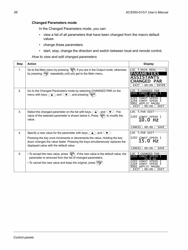
56 ACS550-01/U1 User’s Manual
Changed Parameters modeIn the Changed Parameters mode, you can:
• view a list of all parameters that have been changed from the macro default values
• change these parameters
• start, stop, change the direction and switch between local and remote control.
How to view and edit changed parameters
Step Action Display
1. Go to the Main menu by pressing if you are in the Output mode, otherwise by pressing repeatedly until you get to the Main menu.
2. Go to the Changed Parameters mode by selecting CHANGED PAR on the menu with keys and , and pressing .
3. Select the changed parameter on the list with keys and . The value of the selected parameter is shown below it. Press to modify the value.
4. Specify a new value for the parameter with keys and .
Pressing the key once increments or decrements the value. Holding the key down changes the value faster. Pressing the keys simultaneously replaces the displayed value with the default value.
5. • To accept the new value, press . If the new value is the default value, the parameter is removed from the list of changed parameters.
• To cancel the new value and keep the original, press .
MENU
EXIT
PARAMETERS ASSISTANTSCHANGED PAREXIT ENTER00:00
MAIN MENU 1LOC
ENTER 1202 CONST SPEED 1 10.0 Hz1203 CONST SPEED 21204 CONST SPEED 39902 APPLIC MACRO
CHANGED PAR
EXIT EDIT00:00
LOC
EDIT 1202 CONST SPEED 1
PAR EDIT
10.0 Hz
CANCEL SAVE00:00
LOC
1202 CONST SPEED 1
PAR EDIT
15.0 Hz
CANCEL SAVE00:00
LOC
SAVE
CANCEL
1202 CONST SPEED 1 15.0 Hz1203 CONST SPEED 21204 CONST SPEED 39902 APPLIC MACRO
CHANGED PAR
EXIT EDIT00:00
LOC
Control panels
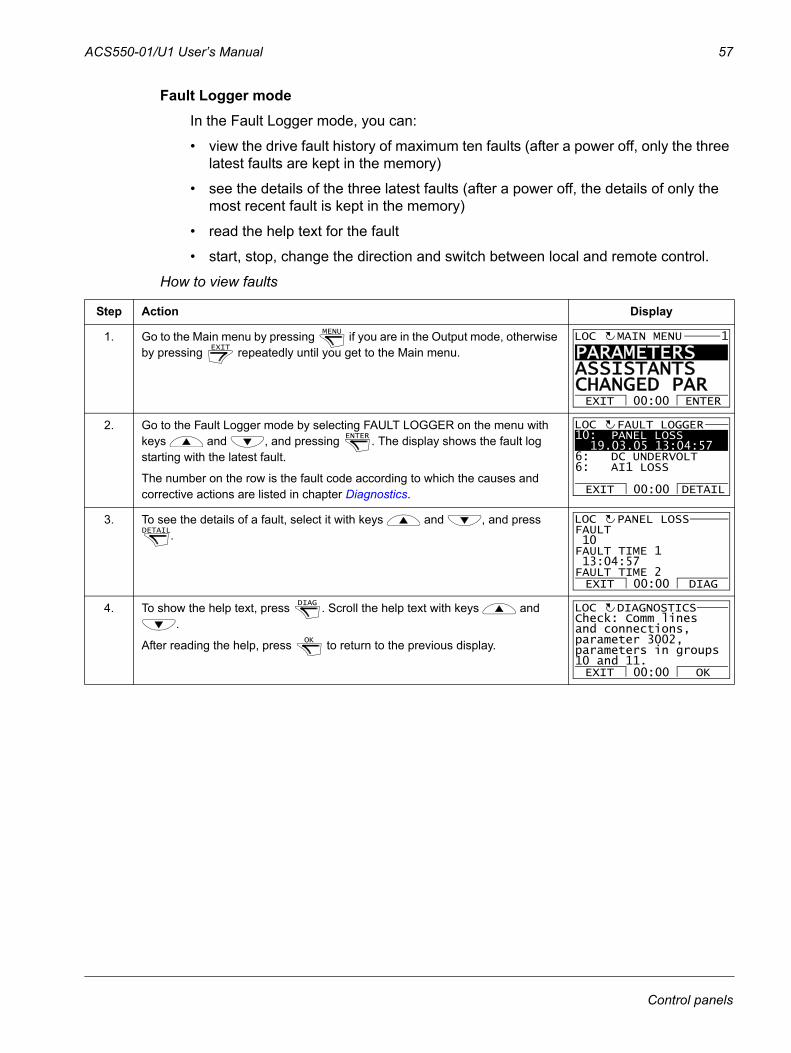
ACS550-01/U1 User’s Manual 57
Fault Logger modeIn the Fault Logger mode, you can:
• view the drive fault history of maximum ten faults (after a power off, only the three latest faults are kept in the memory)
• see the details of the three latest faults (after a power off, the details of only the most recent fault is kept in the memory)
• read the help text for the fault
• start, stop, change the direction and switch between local and remote control.
How to view faults
Step Action Display
1. Go to the Main menu by pressing if you are in the Output mode, otherwise by pressing repeatedly until you get to the Main menu.
2. Go to the Fault Logger mode by selecting FAULT LOGGER on the menu with keys and , and pressing . The display shows the fault log starting with the latest fault.
The number on the row is the fault code according to which the causes and corrective actions are listed in chapter Diagnostics.
3. To see the details of a fault, select it with keys and , and press .
4. To show the help text, press . Scroll the help text with keys and .
After reading the help, press to return to the previous display.
MENU
EXIT
PARAMETERS ASSISTANTSCHANGED PAREXIT ENTER00:00
MAIN MENU 1LOC
ENTER 10: PANEL LOSS
19.03.05 13:04:576: DC UNDERVOLT6: AI1 LOSS
FAULT LOGGER
EXIT DETAIL00:00
LOC
DETAIL FAULT 10FAULT TIME 1 13:04:57FAULT TIME 2
PANEL LOSS
EXIT DIAG00:00
LOC
DIAG
OK
EXIT OK00:00
Check: Comm linesand connections,parameter 3002,parameters in groups10 and 11.
DIAGNOSTICSLOC
Control panels
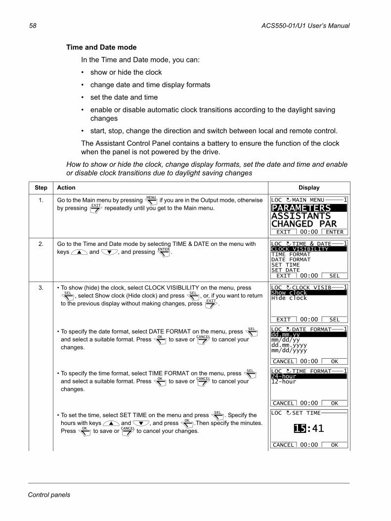
58 ACS550-01/U1 User’s Manual
Time and Date modeIn the Time and Date mode, you can:
• show or hide the clock
• change date and time display formats
• set the date and time
• enable or disable automatic clock transitions according to the daylight saving changes
• start, stop, change the direction and switch between local and remote control.
The Assistant Control Panel contains a battery to ensure the function of the clock when the panel is not powered by the drive.
How to show or hide the clock, change display formats, set the date and time and enable or disable clock transitions due to daylight saving changes
Step Action Display
1. Go to the Main menu by pressing if you are in the Output mode, otherwise by pressing repeatedly until you get to the Main menu.
2. Go to the Time and Date mode by selecting TIME & DATE on the menu with keys and , and pressing .
3. • To show (hide) the clock, select CLOCK VISIBLILITY on the menu, press , select Show clock (Hide clock) and press , or, if you want to return
to the previous display without making changes, press .
• To specify the date format, select DATE FORMAT on the menu, press and select a suitable format. Press to save or to cancel your changes.
• To specify the time format, select TIME FORMAT on the menu, press and select a suitable format. Press to save or to cancel your changes.
• To set the time, select SET TIME on the menu and press . Specify the hours with keys and , and press .Then specify the minutes. Press to save or to cancel your changes.
MENU
EXIT
PARAMETERS ASSISTANTSCHANGED PAREXIT ENTER00:00
MAIN MENU 1LOC
ENTER CLOCK VISIBILITYTIME FORMATDATE FORMATSET TIMESET DATEEXIT SEL00:00
TIME & DATE 1LOC
SEL SEL
EXIT
Show clockHide clock
EXIT SEL00:00
CLOCK VISIB 1LOC
SEL
OK CANCEL
dd.mm.yymm/dd/yydd.mm.yyyymm/dd/yyyy
CANCEL OK00:00
DATE FORMAT 1LOC
SEL
OK CANCEL
24-hour12-hour
CANCEL OK00:00
TIME FORMAT 1LOC
SEL
OK
OK CANCEL
SET TIME
CANCEL OK00:00
LOC
15:41
Control panels
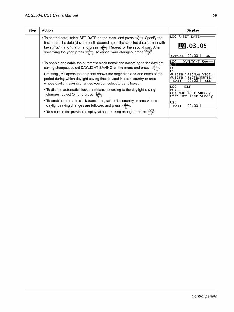
ACS550-01/U1 User’s Manual 59
• To set the date, select SET DATE on the menu and press . Specify the first part of the date (day or month depending on the selected date format) with keys and , and press . Repeat for the second part. After specifying the year, press . To cancel your changes, press .
• To enable or disable the automatic clock transitions according to the daylight saving changes, select DAYLIGHT SAVING on the menu and press .
Pressing opens the help that shows the beginning and end dates of the period during which daylight saving time is used in each country or area whose daylight saving changes you can select to be followed.
• To disable automatic clock transitions according to the daylight saving changes, select Off and press .
• To enable automatic clock transitions, select the country or area whose daylight saving changes are followed and press .
• To return to the previous display without making changes, press .
Step Action DisplaySEL
OK
OK CANCEL
SET DATE
CANCEL OK00:00
LOC
19.03.05
SEL
?
SEL
SEL
EXIT
OffEUUSAustralia1:NSW,Vict..Australia2:Tasmania..EXIT SEL00:00
DAYLIGHT SAV 1LOC
EXIT 00:00
EU:On: Mar last SundayOff: Oct last Sunday
US:
HELPLOC
Control panels
60 ACS550-01/U1 User’s Manual
Parameter Backup modeThe Parameter Backup mode is used to export parameters from one drive to another or to make a backup of the drive parameters. Uploading to the panel stores all drive parameters, including up to two user sets, to the Assistant Control Panel. The full set, partial parameter set (application) and user sets can then be downloaded from the control panel to another drive or the same drive. Uploading and downloading can be performed in local control.
The control panel memory is non-volatile and does not depend on the panel battery.
In the Parameter Backup mode, you can:
• copy all parameters from the drive to the control panel (UPLOAD TO PANEL). This includes all defined user sets of parameters and internal (not adjustable by the user) parameters such as those created by the ID Run.
• view the information about the backup stored to the control panel with UPLOAD TO PANEL (BACKUP INFO). This includes e.g. the type and rating of the drive where the backup was made. It is useful to check this information when you are going to copy the parameters to another drive with DOWNLOAD FULL SET to ensure that the drives match.
• restore the full parameter set from the control panel to the drive (DOWNLOAD FULL SET). This writes all parameters, including the internal non-user-adjustable motor parameters, to the drive. It does not include the user sets of parameters.
Note: Only use this function to restore a drive from a backup or to transfer parameters to systems that are identical to the original system.
• copy a partial parameter set (part of the full set) from the control panel to a drive (DOWNLOAD APPLICATION). The partial set does not include user sets, internal motor parameters, parameters 9905…9909, 1605, 1607, 5201, nor any Group 51: EXT COMM MODULE and Group 53: EFB PROTOCOL parameters.
The source and target drives and their motor sizes do not need to be the same.
• copy USER S1 parameters from the control panel to the drive (DOWNLOAD USER SET1). A user set includes Group 99: START-UP DATA parameters and the internal motor parameters.
The function is only shown on the menu when User Set 1 has been first saved using parameter 9902 APPLIC MACRO (see section User parameter sets on page 83) and then uploaded to the control panel with UPLOAD TO PANEL.
• copy USER S2 parameters from the control panel to the drive (DOWNLOAD USER SET2). As DOWNLOAD USER SET1 above.
• start, stop, change the direction and switch between local and remote control.
Control panels
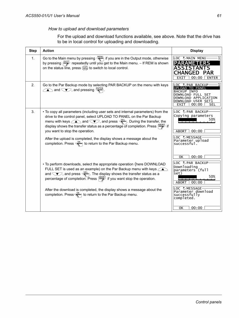
ACS550-01/U1 User’s Manual 61
How to upload and download parameters
For the upload and download functions available, see above. Note that the drive has to be in local control for uploading and downloading.
Step Action Display
1. Go to the Main menu by pressing if you are in the Output mode, otherwise by pressing repeatedly until you get to the Main menu. – If REM is shown on the status line, press to switch to local control.
2. Go to the Par Backup mode by selecting PAR BACKUP on the menu with keys and , and pressing .
3. • To copy all parameters (including user sets and internal parameters) from the drive to the control panel, select UPLOAD TO PANEL on the Par Backup menu with keys and , and press . During the transfer, the display shows the transfer status as a percentage of completion. Press if you want to stop the operation.
After the upload is completed, the display shows a message about the completion. Press to return to the Par Backup menu.
• To perform downloads, select the appropriate operation (here DOWNLOAD FULL SET is used as an example) on the Par Backup menu with keys and , and press . The display shows the transfer status as a percentage of completion. Press if you want stop the operation.
After the download is completed, the display shows a message about the completion. Press to return to the Par Backup menu.
MENU
EXIT
LOCREM
PARAMETERS ASSISTANTSCHANGED PAREXIT ENTER00:00
MAIN MENU 1LOC
ENTER UPLOAD TO PANELBACKUP INFODOWNLOAD FULL SETDOWNLOAD APPLICATIONDOWNLOAD USER SET1EXIT SEL00:00
PAR BACKUP 1LOC
SEL
ABORT
ABORT 00:00
PAR BACKUPLOC
50%Copying parameters
OK
OK 00:00
Parameter uploadsuccessful.
MESSAGELOC
SEL
ABORT
ABORT 00:00
PAR BACKUPLOC
50%
Downloadingparameters (fullset)
OK
OK 00:00
Parameter downloadsuccessfullycompleted.
MESSAGELOC
Control panels
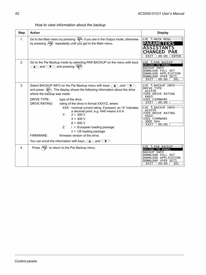
62 ACS550-01/U1 User’s Manual
How to view information about the backup
Step Action Display
1. Go to the Main menu by pressing if you are in the Output mode, otherwise by pressing repeatedly until you get to the Main menu.
2. Go to the Par Backup mode by selecting PAR BACKUP on the menu with keys and , and pressing .
3. Select BACKUP INFO on the Par Backup menu with keys and , and press . The display shows the following information about the drive where the backup was made:
DRIVE TYPE: type of the drive DRIVE RATING: rating of the drive in format XXXYZ, where
XXX: nominal current rating. If present, an “A” indicates a decimal point, e.g. 4A6 means 4.6 A.
Y: 2 = 200 V4 = 400 V6 = 600 V
Z: i = European loading packagen = US loading package
FIRMWARE: firmware version of the drive.
You can scroll the information with keys and .
4. Press to return to the Par Backup menu.
MENU
EXIT
PARAMETERS ASSISTANTSCHANGED PAREXIT ENTER00:00
MAIN MENU 1LOC
ENTER UPLOAD TO PANELBACKUP INFODOWNLOAD FULL SETDOWNLOAD APPLICATIONDOWNLOAD USER SET1EXIT SEL00:00
PAR BACKUP 1LOC
SEL
EXIT 00:00
DRIVE TYPE ACS5503304 DRIVE RATING 4A62i3301 FIRMWARE
BACKUP INFOLOC
EXIT 00:00
ACS5503304 DRIVE RATING 4A62i3301 FIRMWARE 300F hex
BACKUP INFOLOC
EXIT UPLOAD TO PANELBACKUP INFODOWNLOAD FULL SETDOWNLOAD APPLICATIONDOWNLOAD USER SET1EXIT SEL00:00
PAR BACKUP 1LOC
Control panels
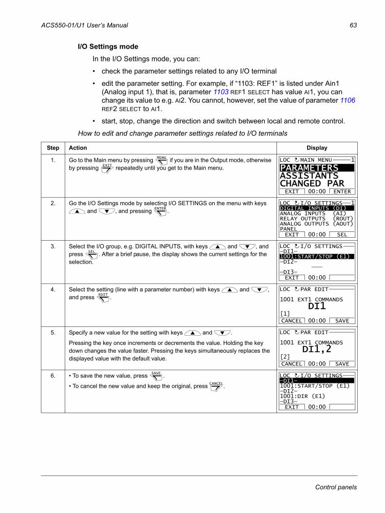
ACS550-01/U1 User’s Manual 63
I/O Settings modeIn the I/O Settings mode, you can:
• check the parameter settings related to any I/O terminal
• edit the parameter setting. For example, if “1103: REF1” is listed under Ain1 (Analog input 1), that is, parameter 1103 REF1 SELECT has value AI1, you can change its value to e.g. AI2. You cannot, however, set the value of parameter 1106 REF2 SELECT to AI1.
• start, stop, change the direction and switch between local and remote control.
How to edit and change parameter settings related to I/O terminals
Step Action Display
1. Go to the Main menu by pressing if you are in the Output mode, otherwise by pressing repeatedly until you get to the Main menu.
2. Go the I/O Settings mode by selecting I/O SETTINGS on the menu with keys and , and pressing .
3. Select the I/O group, e.g. DIGITAL INPUTS, with keys and , and press . After a brief pause, the display shows the current settings for the selection.
4. Select the setting (line with a parameter number) with keys and , and press .
5. Specify a new value for the setting with keys and .
Pressing the key once increments or decrements the value. Holding the key down changes the value faster. Pressing the keys simultaneously replaces the displayed value with the default value.
6. • To save the new value, press .
• To cancel the new value and keep the original, press .
MENU
EXIT
PARAMETERS ASSISTANTSCHANGED PAREXIT ENTER00:00
MAIN MENU 1LOC
ENTER DIGITAL INPUTS (DI)ANALOG INPUTS (AI)RELAY OUTPUTS (ROUT)ANALOG OUTPUTS (AOUT)PANELEXIT SEL00:00
I/O SETTINGS 1LOC
SEL —DI1—1001:START/STOP (E1)—DI2—
—DI3—
I/O SETTINGSLOC
EXIT 00:00
EDIT 1001 EXT1 COMMANDS
PAR EDIT
DI1
CANCEL SAVE00:00[1]
LOC
1001 EXT1 COMMANDS
PAR EDIT
DI1,2
CANCEL SAVE00:00[2]
LOC
SAVE
CANCEL
—DI1—1001:START/STOP (E1)—DI2—1001:DIR (E1)—DI3—EXIT 00:00
I/O SETTINGSLOC
Control panels
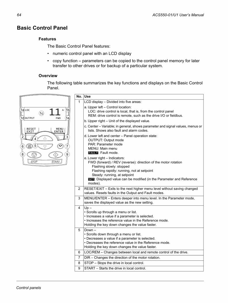
64 ACS550-01/U1 User’s Manual
Basic Control Panel
FeaturesThe Basic Control Panel features:
• numeric control panel with an LCD display
• copy function – parameters can be copied to the control panel memory for later transfer to other drives or for backup of a particular system.
OverviewThe following table summarizes the key functions and displays on the Basic Control Panel.
No. Use1 LCD display – Divided into five areas:
a. Upper left – Control location:LOC: drive control is local, that is, from the control panelREM: drive control is remote, such as the drive I/O or fieldbus.
b. Upper right – Unit of the displayed value.c. Center – Variable; in general, shows parameter and signal values, menus or
lists. Shows also fault and alarm codes.d. Lower left and center – Panel operation state:
OUTPUT: Output modePAR: Parameter modeMENU: Main menu
: Fault mode.e. Lower right – Indicators:
FWD (forward) / REV (reverse): direction of the motor rotation Flashing slowly: stopped Flashing rapidly: running, not at setpoint Steady: running, at setpoint
: Displayed value can be modified (in the Parameter and Reference modes).
2 RESET/EXIT – Exits to the next higher menu level without saving changed values. Resets faults in the Output and Fault modes.
3 MENU/ENTER – Enters deeper into menu level. In the Parameter mode, saves the displayed value as the new setting.
4 Up – • Scrolls up through a menu or list. • Increases a value if a parameter is selected.• Increases the reference value in the Reference mode.Holding the key down changes the value faster.
5 Down – • Scrolls down through a menu or list. • Decreases a value if a parameter is selected.• Decreases the reference value in the Reference mode.Holding the key down changes the value faster.
6 LOC/REM – Changes between local and remote control of the drive.7 DIR – Changes the direction of the motor rotation.8 STOP – Stops the drive in local control. 9 START – Starts the drive in local control.
FAULT
SET
RESETEXIT
MENUENTER
2 34
56 7
8 9
1cLOC A
OUTPUT FWD
11. 1b
1e
1a
1d
Control panels
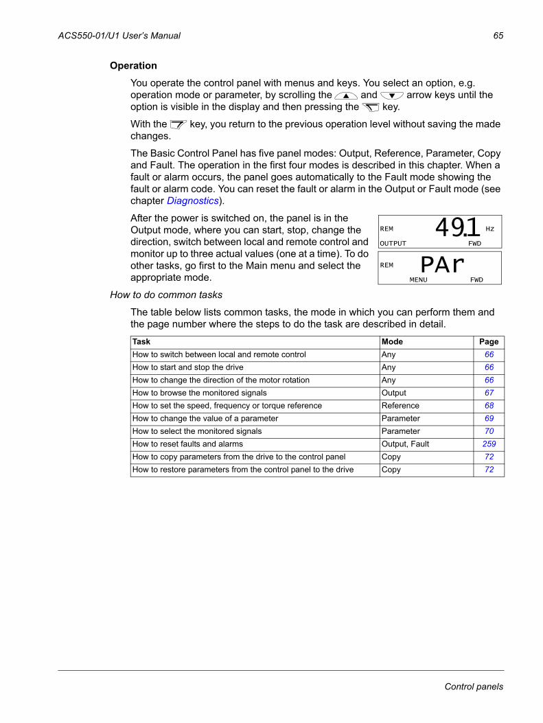
ACS550-01/U1 User’s Manual 65
OperationYou operate the control panel with menus and keys. You select an option, e.g. operation mode or parameter, by scrolling the and arrow keys until the option is visible in the display and then pressing the key.
With the key, you return to the previous operation level without saving the made changes.
The Basic Control Panel has five panel modes: Output, Reference, Parameter, Copy and Fault. The operation in the first four modes is described in this chapter. When a fault or alarm occurs, the panel goes automatically to the Fault mode showing the fault or alarm code. You can reset the fault or alarm in the Output or Fault mode (see chapter Diagnostics).
After the power is switched on, the panel is in the Output mode, where you can start, stop, change the direction, switch between local and remote control and monitor up to three actual values (one at a time). To do other tasks, go first to the Main menu and select the appropriate mode.
How to do common tasks
The table below lists common tasks, the mode in which you can perform them and the page number where the steps to do the task are described in detail.
Task Mode PageHow to switch between local and remote control Any 66How to start and stop the drive Any 66How to change the direction of the motor rotation Any 66How to browse the monitored signals Output 67How to set the speed, frequency or torque reference Reference 68How to change the value of a parameter Parameter 69How to select the monitored signals Parameter 70How to reset faults and alarms Output, Fault 259How to copy parameters from the drive to the control panel Copy 72How to restore parameters from the control panel to the drive Copy 72
REM Hz
OUTPUT FWD
491. REM
MENU FWD
PAr
Control panels
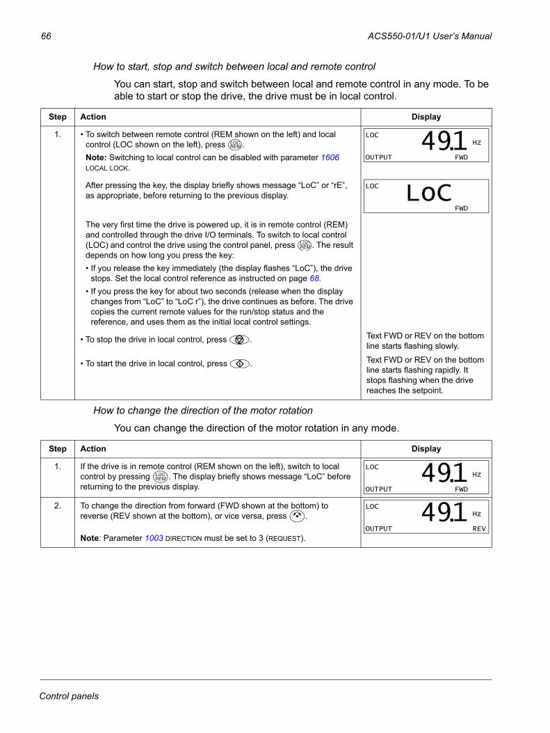
66 ACS550-01/U1 User’s Manual
How to start, stop and switch between local and remote control
You can start, stop and switch between local and remote control in any mode. To be able to start or stop the drive, the drive must be in local control.
How to change the direction of the motor rotation
You can change the direction of the motor rotation in any mode.
Step Action Display
1. • To switch between remote control (REM shown on the left) and local control (LOC shown on the left), press .Note: Switching to local control can be disabled with parameter 1606 LOCAL LOCK.
After pressing the key, the display briefly shows message “LoC” or “rE”, as appropriate, before returning to the previous display.
The very first time the drive is powered up, it is in remote control (REM) and controlled through the drive I/O terminals. To switch to local control (LOC) and control the drive using the control panel, press . The result depends on how long you press the key:• If you release the key immediately (the display flashes “LoC”), the drive
stops. Set the local control reference as instructed on page 68.• If you press the key for about two seconds (release when the display
changes from “LoC” to “LoC r”), the drive continues as before. The drive copies the current remote values for the run/stop status and the reference, and uses them as the initial local control settings.
• To stop the drive in local control, press . Text FWD or REV on the bottom line starts flashing slowly.
• To start the drive in local control, press . Text FWD or REV on the bottom line starts flashing rapidly. It stops flashing when the drive reaches the setpoint.
Step Action Display
1. If the drive is in remote control (REM shown on the left), switch to local control by pressing . The display briefly shows message “LoC” before returning to the previous display.
2. To change the direction from forward (FWD shown at the bottom) to reverse (REV shown at the bottom), or vice versa, press .
Note: Parameter 1003 DIRECTION must be set to 3 (REQUEST).
LOCREM
LOC Hz
OUTPUT FWD
491.
LOC
FWD
LoC
LOCREM
LOCREM
LOC Hz
OUTPUT FWD
491.LOC Hz
OUTPUT REV
491.
Control panels
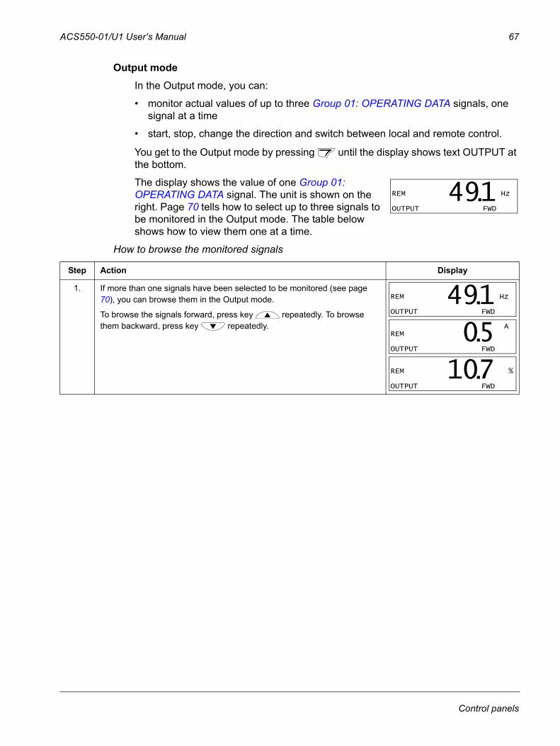
ACS550-01/U1 User’s Manual 67
Output modeIn the Output mode, you can:
• monitor actual values of up to three Group 01: OPERATING DATA signals, one signal at a time
• start, stop, change the direction and switch between local and remote control.
You get to the Output mode by pressing until the display shows text OUTPUT at the bottom.
The display shows the value of one Group 01: OPERATING DATA signal. The unit is shown on the right. Page 70 tells how to select up to three signals to be monitored in the Output mode. The table below shows how to view them one at a time.
How to browse the monitored signals
Step Action Display
1. If more than one signals have been selected to be monitored (see page 70), you can browse them in the Output mode.
To browse the signals forward, press key repeatedly. To browse them backward, press key repeatedly.
REM Hz
OUTPUT FWD
491.
REM Hz
OUTPUT FWD
491. AREM
OUTPUT FWD
05. REM %
OUTPUT FWD
107.
Control panels
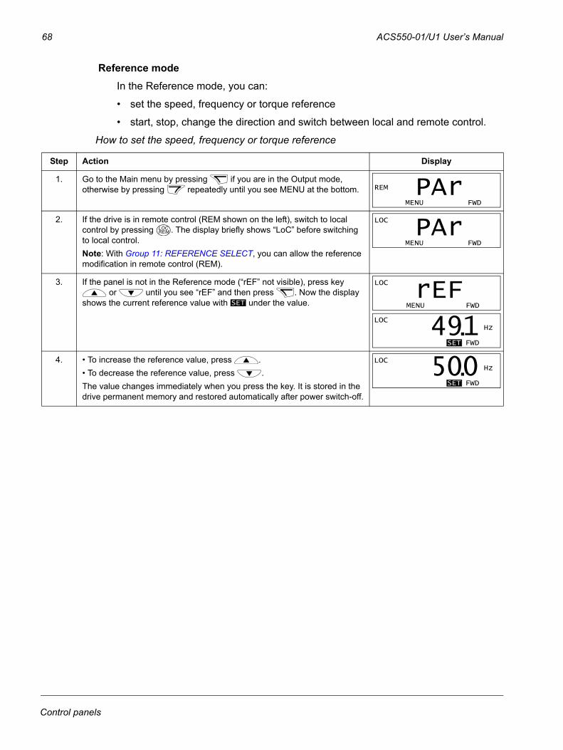
68 ACS550-01/U1 User’s Manual
Reference modeIn the Reference mode, you can:
• set the speed, frequency or torque reference
• start, stop, change the direction and switch between local and remote control.
How to set the speed, frequency or torque reference
Step Action Display
1. Go to the Main menu by pressing if you are in the Output mode, otherwise by pressing repeatedly until you see MENU at the bottom.
2. If the drive is in remote control (REM shown on the left), switch to local control by pressing . The display briefly shows “LoC” before switching to local control.Note: With Group 11: REFERENCE SELECT, you can allow the reference modification in remote control (REM).
3. If the panel is not in the Reference mode (“rEF” not visible), press key or until you see “rEF” and then press . Now the display
shows the current reference value with under the value.
4. • To increase the reference value, press . • To decrease the reference value, press .The value changes immediately when you press the key. It is stored in the drive permanent memory and restored automatically after power switch-off.
REM
MENU FWD
PAr
LOCREM
LOC
MENU FWD
PAr
SET
LOC
MENU FWD
rEF LOC Hz
SET FWD
491.LOC Hz
SET FWD
500.
Control panels
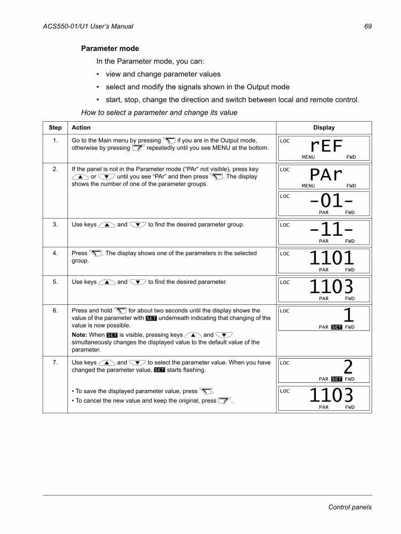
ACS550-01/U1 User’s Manual 69
Parameter modeIn the Parameter mode, you can:
• view and change parameter values
• select and modify the signals shown in the Output mode
• start, stop, change the direction and switch between local and remote control.
How to select a parameter and change its value
Step Action Display
1. Go to the Main menu by pressing if you are in the Output mode, otherwise by pressing repeatedly until you see MENU at the bottom.
2. If the panel is not in the Parameter mode (“PAr” not visible), press key or until you see “PAr” and then press . The display
shows the number of one of the parameter groups.
3. Use keys and to find the desired parameter group.
4. Press . The display shows one of the parameters in the selected group.
5. Use keys and to find the desired parameter.
6. Press and hold for about two seconds until the display shows the value of the parameter with underneath indicating that changing of the value is now possible. Note: When is visible, pressing keys and simultaneously changes the displayed value to the default value of the parameter.
7. Use keys and to select the parameter value. When you have changed the parameter value, starts flashing.
• To save the displayed parameter value, press .• To cancel the new value and keep the original, press .
LOC
MENU FWD
rEF LOC
MENU FWD
PAr LOC
PAR FWD
-01- LOC
PAR FWD
-11- LOC
PAR FWD
1101 LOC
PAR FWD
1103
SET
SET
LOC
PAR SET FWD
1
SET
LOC
PAR SET FWD
2 LOC
PAR FWD
1103
Control panels
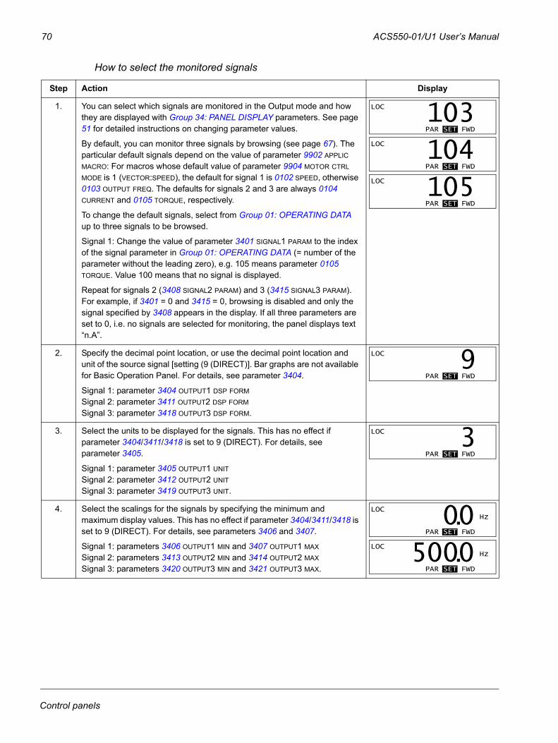
70 ACS550-01/U1 User’s Manual
How to select the monitored signals
Step Action Display
1. You can select which signals are monitored in the Output mode and how they are displayed with Group 34: PANEL DISPLAY parameters. See page 51 for detailed instructions on changing parameter values.
By default, you can monitor three signals by browsing (see page 67). The particular default signals depend on the value of parameter 9902 APPLIC MACRO: For macros whose default value of parameter 9904 MOTOR CTRL MODE is 1 (VECTOR:SPEED), the default for signal 1 is 0102 SPEED, otherwise 0103 OUTPUT FREQ. The defaults for signals 2 and 3 are always 0104 CURRENT and 0105 TORQUE, respectively.
To change the default signals, select from Group 01: OPERATING DATA up to three signals to be browsed.
Signal 1: Change the value of parameter 3401 SIGNAL1 PARAM to the index of the signal parameter in Group 01: OPERATING DATA (= number of the parameter without the leading zero), e.g. 105 means parameter 0105 TORQUE. Value 100 means that no signal is displayed.
Repeat for signals 2 (3408 SIGNAL2 PARAM) and 3 (3415 SIGNAL3 PARAM). For example, if 3401 = 0 and 3415 = 0, browsing is disabled and only the signal specified by 3408 appears in the display. If all three parameters are set to 0, i.e. no signals are selected for monitoring, the panel displays text “n.A”.
2. Specify the decimal point location, or use the decimal point location and unit of the source signal [setting (9 (DIRECT)]. Bar graphs are not available for Basic Operation Panel. For details, see parameter 3404.
Signal 1: parameter 3404 OUTPUT1 DSP FORM
Signal 2: parameter 3411 OUTPUT2 DSP FORM
Signal 3: parameter 3418 OUTPUT3 DSP FORM.
3. Select the units to be displayed for the signals. This has no effect if parameter 3404/3411/3418 is set to 9 (DIRECT). For details, see parameter 3405.
Signal 1: parameter 3405 OUTPUT1 UNIT
Signal 2: parameter 3412 OUTPUT2 UNIT
Signal 3: parameter 3419 OUTPUT3 UNIT.
4. Select the scalings for the signals by specifying the minimum and maximum display values. This has no effect if parameter 3404/3411/3418 is set to 9 (DIRECT). For details, see parameters 3406 and 3407.
Signal 1: parameters 3406 OUTPUT1 MIN and 3407 OUTPUT1 MAX
Signal 2: parameters 3413 OUTPUT2 MIN and 3414 OUTPUT2 MAX
Signal 3: parameters 3420 OUTPUT3 MIN and 3421 OUTPUT3 MAX.
LOC
PAR SET FWD
103 LOC
PAR SET FWD
104 LOC
PAR SET FWD
105
LOC
PAR SET FWD
9
LOC
PAR SET FWD
3
LOC Hz
PAR SET FWD
00.LOC Hz
PAR SET FWD
5000.
Control panels
ACS550-01/U1 User’s Manual 71
Copy modeThe Basic Control Panel can store a full set of drive parameters and up to two user sets of drive parameters to the control panel. The control panel memory is non-volatile.
In the Copy mode, you can:
• copy all parameters from the drive to the control panel (uL – Upload). This includes all defined user sets of parameters and internal (not adjustable by the user) parameters such as those created by the ID Run.
• restore the full parameter set from the control panel to the drive (dL A – Download All). This writes all parameters, including the internal non-user-adjustable motor parameters, to the drive. It does not include the user sets of parameters.
Note: Only use this function to restore a drive, or to transfer parameters to systems that are identical to the original system.
• copy a partial parameter set from the control panel to a drive (dL P – Download Partial). The partial set does not include user sets, internal motor parameters, parameters 9905…9909, 1605, 1607, 5201, nor any Group 51: EXT COMM MODULE and Group 53: EFB PROTOCOL parameters.
The source and target drives and their motor sizes do not need to be the same.
• copy USER S1 parameters from the control panel to the drive (dL u1 – Download User Set 1). A user set includes Group 99: START-UP DATA parameters and the internal motor parameters.
The function is only shown on the menu when User Set 1 has been first saved using parameter 9902 APPLIC MACRO (see section User parameter sets on page 83) and then uploaded to panel.
• copy USER S2 parameters from the control panel to the drive (dL u2 – Download User Set 2). As dL u1 – Download User Set 1 above.
• start, stop, change the direction and switch between local and remote control.
Control panels
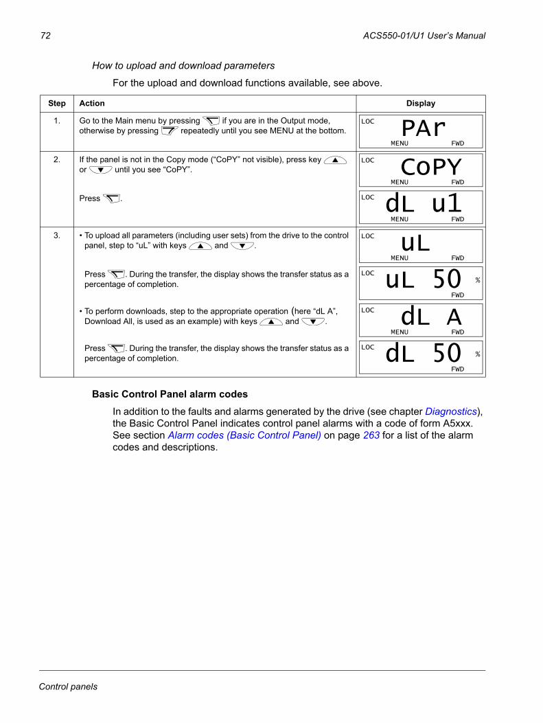
72 ACS550-01/U1 User’s Manual
How to upload and download parameters
For the upload and download functions available, see above.
Basic Control Panel alarm codesIn addition to the faults and alarms generated by the drive (see chapter Diagnostics), the Basic Control Panel indicates control panel alarms with a code of form A5xxx. See section Alarm codes (Basic Control Panel) on page 263 for a list of the alarm codes and descriptions.
Step Action Display
1. Go to the Main menu by pressing if you are in the Output mode, otherwise by pressing repeatedly until you see MENU at the bottom.
2. If the panel is not in the Copy mode (“CoPY” not visible), press key or until you see “CoPY”.
Press .
3. • To upload all parameters (including user sets) from the drive to the control panel, step to “uL” with keys and .
Press . During the transfer, the display shows the transfer status as a percentage of completion.
• To perform downloads, step to the appropriate operation (here “dL A”, Download All, is used as an example) with keys and .
Press . During the transfer, the display shows the transfer status as a percentage of completion.
LOC
MENU FWD
PAr LOC
MENU FWD
CoPY LOC
MENU FWD
dL u1 LOC
MENU FWD
uL LOC %
FWD
uL 50 LOC
MENU FWD
dL A LOC %
FWD
dL 50
Control panels
ACS550-01/U1 User’s Manual 73
Application macros
Macros change a group of parameters to new, predefined values. Use macros to minimize the need for manual editing of parameters. Selecting a macro sets all other parameters to their default values, except:
• Group 99: START-UP DATA parameters (except parameter 9904)
• 1602 PARAMETER LOCK
• 1607 PARAM SAVE
• 3018 COMM FAULT FUNC and 3019 COMM FAULT TIME
• 9802 COMM PROT SEL
• Group 50: ENCODER … Group 53: EFB PROTOCOL parameters
• Group 29: MAINTENANCE TRIG parameters.
After selecting a macro, you can make additional parameter changes manually with the control panel.
You enable application macros by setting the value for parameter 9902 APPLIC MACRO. By default, 1, ABB STANDARD, is the enabled macro.
The following sections describe each of the application macros and provide a connection example for each macro.
The last section in this chapter, Macro default values for parameters, lists the parameters that the macros change and the default values established by each macro.
Application macros
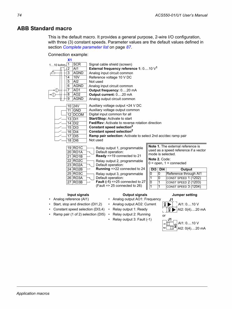
74 ACS550-01/U1 User’s Manual
ABB Standard macroThis is the default macro. It provides a general purpose, 2-wire I/O configuration, with three (3) constant speeds. Parameter values are the default values defined in section Complete parameter list on page 87.
Connection example:
Input signals Output signals Jumper setting• Analog reference (AI1)• Start, stop and direction (DI1,2)• Constant speed selection (DI3,4)• Ramp pair (1 of 2) selection (DI5)
• Analog output AO1: Frequency• Analog output AO2: Current• Relay output 1: Ready• Relay output 2: Running• Relay output 3: Fault (-1)
or
External frequency reference 1: 0…10 V11 SCR2 AI13 AGND4 10V5 AI26 AGND7 AO18 AO29 AGND
10 24V11 GND12 DCOM13 DI114 DI215 DI316 DI417 DI518 DI6
19 RO1C20 RO1A21 RO1B22 RO2C23 RO2A24 RO2B25 RO3C26 RO3A27 RO3B
Reference voltage 10 V DC
Output frequency: 0…20 mA
Start/Stop: Activate to startFwd/Rev: Activate to reverse rotation directionConstant speed selection2
Constant speed selection2
Ramp pair selection: Activate to select 2nd acc/dec ramp pair
Relay output 1, programmableDefault operation:
Relay output 2, programmableDefault operation:
Relay output 3, programmableDefault operation:
Note 1. The external reference is used as a speed reference if a vector mode is selected.Note 2. Code: 0 = open, 1 = connected
DI3 DI4 Output0 0 Reference through AI11 0 CONST SPEED 1 (1202)0 1 CONST SPEED 2 (1203)1 1 CONST SPEED 3 (1204)
Output current: 0…20 mA
Not used
Ready =>19 connected to 21
Running =>22 connected to 24
Fault (-1) =>25 connected to 27
Analog input circuit common
Not used
Analog output circuit common
Auxiliary voltage output +24 V DCAuxiliary voltage output commonDigital input common for all
Signal cable shield (screen)
Analog input circuit common
(Fault => 25 connected to 26)
1…10 kohmX1
J1AI1: 0…10 VAI2: 0(4)…20 mA
ON
ON
AI1: 0…10 VAI2: 0(4)…20 mA
ON
12
J1
Application macros
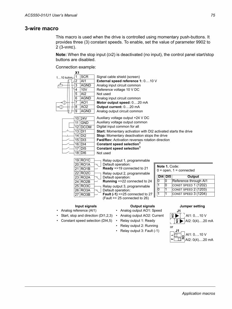
ACS550-01/U1 User’s Manual 75
3-wire macroThis macro is used when the drive is controlled using momentary push-buttons. It provides three (3) constant speeds. To enable, set the value of parameter 9902 to 2 (3-WIRE).
Note: When the stop input (DI2) is deactivated (no input), the control panel start/stop buttons are disabled.
Connection example:
Input signals Output signals Jumper setting• Analog reference (AI1)• Start, stop and direction (DI1,2,3)• Constant speed selection (DI4,5)
• Analog output AO1: Speed• Analog output AO2: Current• Relay output 1: Ready• Relay output 2: Running• Relay output 3: Fault (-1)
or
1 SCR2 AI13 AGND4 10V5 AI26 AGND7 AO18 AO29 AGND
10 24V11 GND12 DCOM13 DI114 DI215 DI316 DI417 DI518 DI6
19 RO1C20 RO1A21 RO1B22 RO2C23 RO2A24 RO2B25 RO3C26 RO3A27 RO3B
External speed reference 1: 0…10 V
Reference voltage 10 V DC
Motor output speed: 0…20 mA
Constant speed selection1
Constant speed selection1
Relay output 1, programmableDefault operation:
Relay output 2, programmableDefault operation:
Relay output 3, programmableDefault operation:
Output current: 0…20 mA
Ready =>19 connected to 21
Running =>22 connected to 24
Fault (-1) =>25 connected to 27
Analog input circuit common
Not used
Analog output circuit common
Auxiliary voltage output +24 V DCAuxiliary voltage output commonDigital input common for all
Signal cable shield (screen)
Analog input circuit common
Note 1. Code:0 = open, 1 = connected
DI4 DI5 Output0 0 Reference through AI11 0 CONST SPEED 1 (1202)0 1 CONST SPEED 2 (1203)1 1 CONST SPEED 3 (1204)
Start: Momentary activation with DI2 activated starts the driveStop: Momentary deactivation stops the driveFwd/Rev: Activation reverses rotation direction
Not used
(Fault => 25 connected to 26)
X11…10 kohm
J1AI1: 0…10 VAI2: 0(4)…20 mA
ON
ON
AI1: 0…10 VAI2: 0(4)…20 mA
ON
12
J1
Application macros
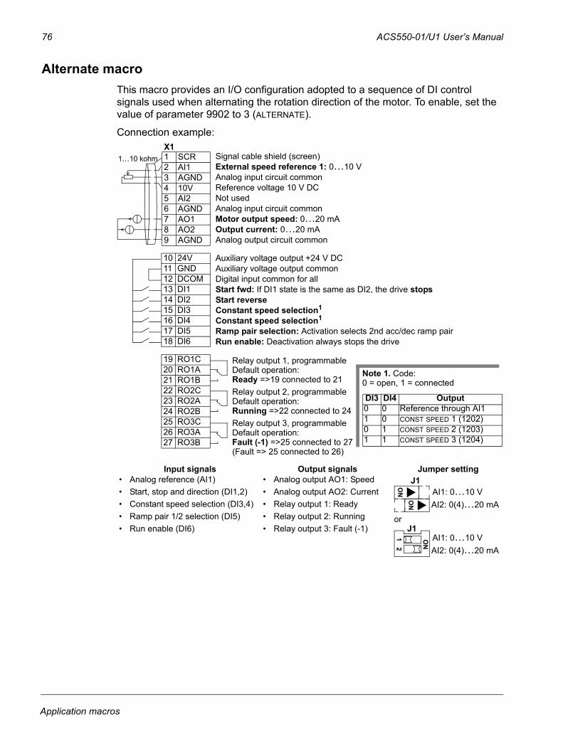
76 ACS550-01/U1 User’s Manual
Alternate macroThis macro provides an I/O configuration adopted to a sequence of DI control signals used when alternating the rotation direction of the motor. To enable, set the value of parameter 9902 to 3 (ALTERNATE).
Connection example:
Input signals Output signals Jumper setting• Analog reference (AI1)• Start, stop and direction (DI1,2)• Constant speed selection (DI3,4)• Ramp pair 1/2 selection (DI5)• Run enable (DI6)
• Analog output AO1: Speed• Analog output AO2: Current• Relay output 1: Ready• Relay output 2: Running• Relay output 3: Fault (-1)
or
1 SCR2 AI13 AGND4 10V5 AI26 AGND7 AO18 AO29 AGND
10 24V11 GND12 DCOM13 DI114 DI215 DI316 DI417 DI518 DI6
19 RO1C20 RO1A21 RO1B22 RO2C23 RO2A24 RO2B25 RO3C26 RO3A27 RO3B
External speed reference 1: 0…10 V
Reference voltage 10 V DC
Motor output speed: 0…20 mA
Constant speed selection1
Constant speed selection1
Relay output 1, programmableDefault operation:
Relay output 2, programmableDefault operation:
Relay output 3, programmableDefault operation:
Output current: 0…20 mA
Ready =>19 connected to 21
Running =>22 connected to 24
Fault (-1) =>25 connected to 27
Analog input circuit common
Not used
Analog output circuit common
Auxiliary voltage output +24 V DCAuxiliary voltage output commonDigital input common for all
Signal cable shield (screen)
Analog input circuit common
Note 1. Code:0 = open, 1 = connected
DI3 DI4 Output0 0 Reference through AI11 0 CONST SPEED 1 (1202)0 1 CONST SPEED 2 (1203)1 1 CONST SPEED 3 (1204)
Start fwd: If DI1 state is the same as DI2, the drive stopsStart reverse
Ramp pair selection: Activation selects 2nd acc/dec ramp pair Run enable: Deactivation always stops the drive
(Fault => 25 connected to 26)
X11…10 kohm
J1AI1: 0…10 VAI2: 0(4)…20 mA
ON
ON
AI1: 0…10 VAI2: 0(4)…20 mA
ON
12
J1
Application macros
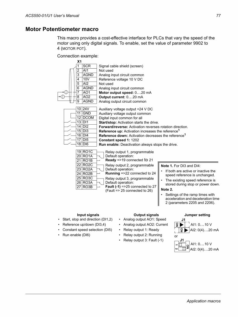
ACS550-01/U1 User’s Manual 77
Motor Potentiometer macroThis macro provides a cost-effective interface for PLCs that vary the speed of the motor using only digital signals. To enable, set the value of parameter 9902 to 4 (MOTOR POT).
Connection example:
Input signals Output signals Jumper setting• Start, stop and direction (DI1,2)• Reference up/down (DI3,4)• Constant speed selection (DI5)• Run enable (DI6)
• Analog output AO1: Speed• Analog output AO2: Current• Relay output 1: Ready• Relay output 2: Running• Relay output 3: Fault (-1)
or
1 SCR2 AI13 AGND4 10V5 AI26 AGND7 AO18 AO29 AGND
10 24V11 GND12 DCOM13 DI114 DI215 DI316 DI417 DI518 DI6
19 RO1C20 RO1A21 RO1B22 RO2C23 RO2A24 RO2B25 RO3C26 RO3A27 RO3B
Not used
Reference voltage 10 V DC
Motor output speed: 0…20 mA
Reference up: Activation increases the reference1 Reference down: Activation decreases the reference1
Relay output 1, programmableDefault operation:
Relay output 2, programmableDefault operation:
Relay output 3, programmableDefault operation:
Output current: 0…20 mA
Ready =>19 connected to 21
Running =>22 connected to 24
Fault (-1) =>25 connected to 27
Analog input circuit common
Not used
Analog output circuit common
Auxiliary voltage output +24 V DCAuxiliary voltage output commonDigital input common for all
Signal cable shield (screen)
Analog input circuit common
Note 1. For DI3 and DI4:• If both are active or inactive the
speed reference is unchanged.• The existing speed reference is
stored during stop or power down.Note 2.• Settings of the ramp times with
acceleration and deceleration time 2 (parameters 2205 and 2206).
Start/stop: Activation starts the drive.Forward/reverse: Activation reverses rotation direction.
Constant speed 1: 1202 Run enable: Deactivation always stops the drive.
(Fault => 25 connected to 26)
X1
J1AI1: 0…10 VAI2: 0(4)…20 mA
ON
ON
AI1: 0…10 VAI2: 0(4)…20 mA
ON
12
J1
Application macros
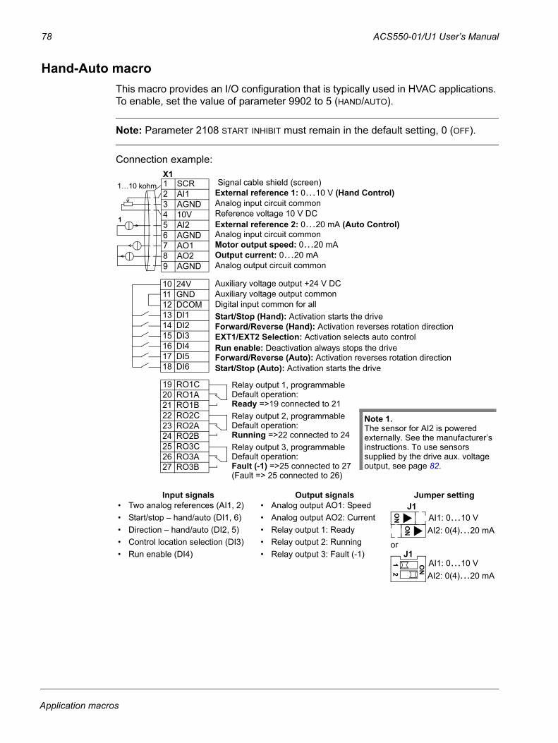
78 ACS550-01/U1 User’s Manual
Hand-Auto macroThis macro provides an I/O configuration that is typically used in HVAC applications. To enable, set the value of parameter 9902 to 5 (HAND/AUTO).
Note: Parameter 2108 START INHIBIT must remain in the default setting, 0 (OFF).
Connection example:
Input signals Output signals Jumper setting• Two analog references (AI1, 2)• Start/stop – hand/auto (DI1, 6)• Direction – hand/auto (DI2, 5)• Control location selection (DI3)• Run enable (DI4)
• Analog output AO1: Speed• Analog output AO2: Current• Relay output 1: Ready• Relay output 2: Running• Relay output 3: Fault (-1)
or
1 SCR2 AI13 AGND4 10V5 AI26 AGND7 AO18 AO29 AGND
10 24V11 GND12 DCOM13 DI114 DI215 DI316 DI417 DI518 DI6
19 RO1C20 RO1A21 RO1B22 RO2C23 RO2A24 RO2B25 RO3C26 RO3A27 RO3B
Start/Stop (Hand): Activation starts the driveForward/Reverse (Hand): Activation reverses rotation directionEXT1/EXT2 Selection: Activation selects auto control
Forward/Reverse (Auto): Activation reverses rotation direction Start/Stop (Auto): Activation starts the drive
Run enable: Deactivation always stops the drive
External reference 1: 0…10 V (Hand Control)
Reference voltage 10 V DC
Motor output speed: 0…20 mAOutput current: 0…20 mA
Analog input circuit common
Analog output circuit common
Auxiliary voltage output +24 V DCAuxiliary voltage output commonDigital input common for all
Signal cable shield (screen)
Analog input circuit common External reference 2: 0…20 mA (Auto Control)
Relay output 1, programmableDefault operation:
Relay output 2, programmableDefault operation:
Relay output 3, programmableDefault operation:
Ready =>19 connected to 21
Running =>22 connected to 24
Fault (-1) =>25 connected to 27(Fault => 25 connected to 26)
1
Note 1. The sensor for AI2 is powered externally. See the manufacturer’s instructions. To use sensors supplied by the drive aux. voltage output, see page 82.
X11…10 kohm
J1AI1: 0…10 VAI2: 0(4)…20 mA
ON
ON
AI1: 0…10 VAI2: 0(4)…20 mA
ON
12
J1
Application macros
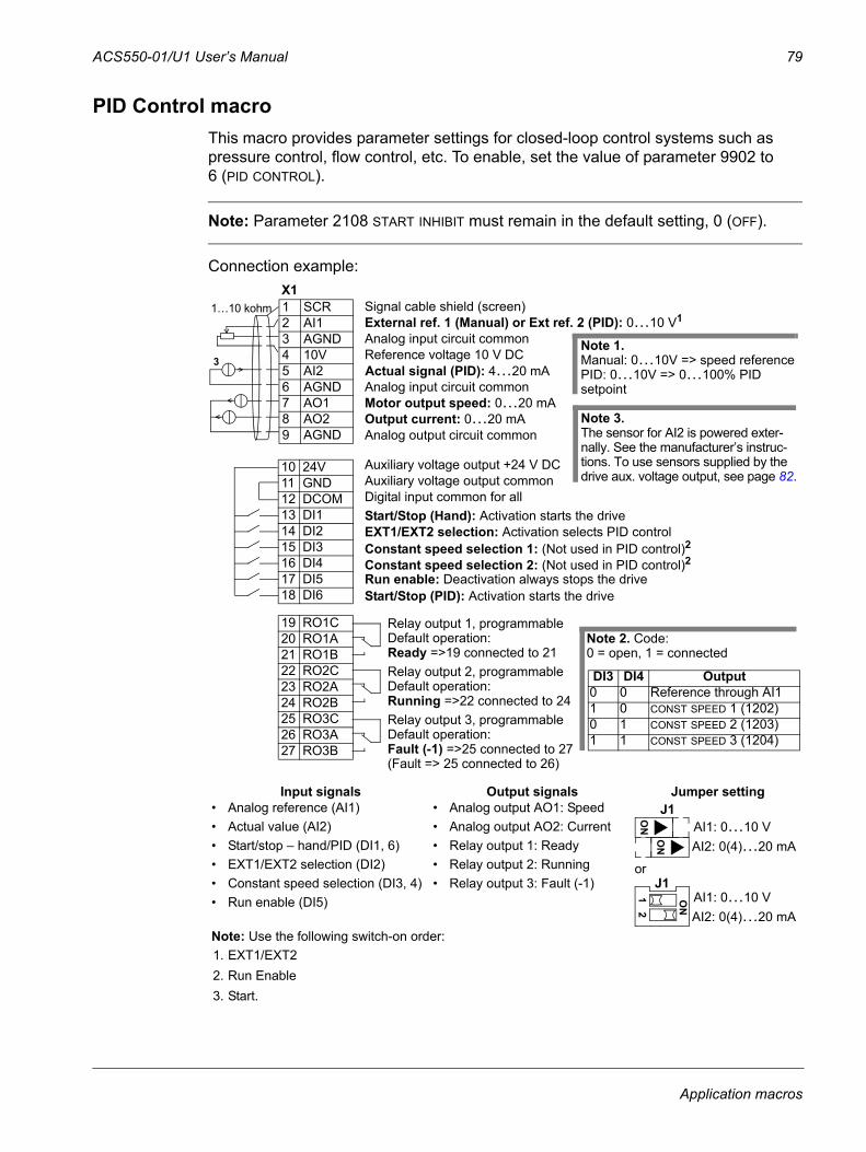
ACS550-01/U1 User’s Manual 79
PID Control macroThis macro provides parameter settings for closed-loop control systems such as pressure control, flow control, etc. To enable, set the value of parameter 9902 to 6 (PID CONTROL).
Note: Parameter 2108 START INHIBIT must remain in the default setting, 0 (OFF).
Connection example:
Input signals Output signals Jumper setting• Analog reference (AI1)• Actual value (AI2)• Start/stop – hand/PID (DI1, 6)• EXT1/EXT2 selection (DI2)• Constant speed selection (DI3, 4)• Run enable (DI5)
• Analog output AO1: Speed• Analog output AO2: Current• Relay output 1: Ready• Relay output 2: Running• Relay output 3: Fault (-1)
or
Note: Use the following switch-on order:1. EXT1/EXT22. Run Enable3. Start.
1 SCR2 AI13 AGND4 10V5 AI26 AGND7 AO18 AO29 AGND
10 24V11 GND12 DCOM13 DI114 DI215 DI316 DI417 DI518 DI6
19 RO1C20 RO1A21 RO1B22 RO2C23 RO2A24 RO2B25 RO3C26 RO3A27 RO3B
Start/Stop (Hand): Activation starts the drive
Constant speed selection 1: (Not used in PID control)2EXT1/EXT2 selection: Activation selects PID control
Constant speed selection 2: (Not used in PID control)2
Start/Stop (PID): Activation starts the driveRun enable: Deactivation always stops the drive
External ref. 1 (Manual) or Ext ref. 2 (PID): 0…10 V1
Reference voltage 10 V DC
Motor output speed: 0…20 mAOutput current: 0…20 mA
Analog input circuit common
Analog output circuit common
Auxiliary voltage output +24 V DCAuxiliary voltage output commonDigital input common for all
Signal cable shield (screen)
Analog input circuit common
Relay output 1, programmableDefault operation:
Relay output 2, programmableDefault operation:
Relay output 3, programmableDefault operation:
Ready =>19 connected to 21
Running =>22 connected to 24
Fault (-1) =>25 connected to 27
Note 2. Code:0 = open, 1 = connected
DI3 DI4 Output0 0 Reference through AI11 0 CONST SPEED 1 (1202)0 1 CONST SPEED 2 (1203)1 1 CONST SPEED 3 (1204)
Note 1. Manual: 0…10V => speed referencePID: 0…10V => 0…100% PID setpoint
(Fault => 25 connected to 26)
Note 3. The sensor for AI2 is powered exter-nally. See the manufacturer’s instruc-tions. To use sensors supplied by the drive aux. voltage output, see page 82.
3
X11…10 kohm
Actual signal (PID): 4…20 mA
J1AI1: 0…10 VAI2: 0(4)…20 mA
ON
ON
AI1: 0…10 VAI2: 0(4)…20 mA
ON
12
J1
Application macros
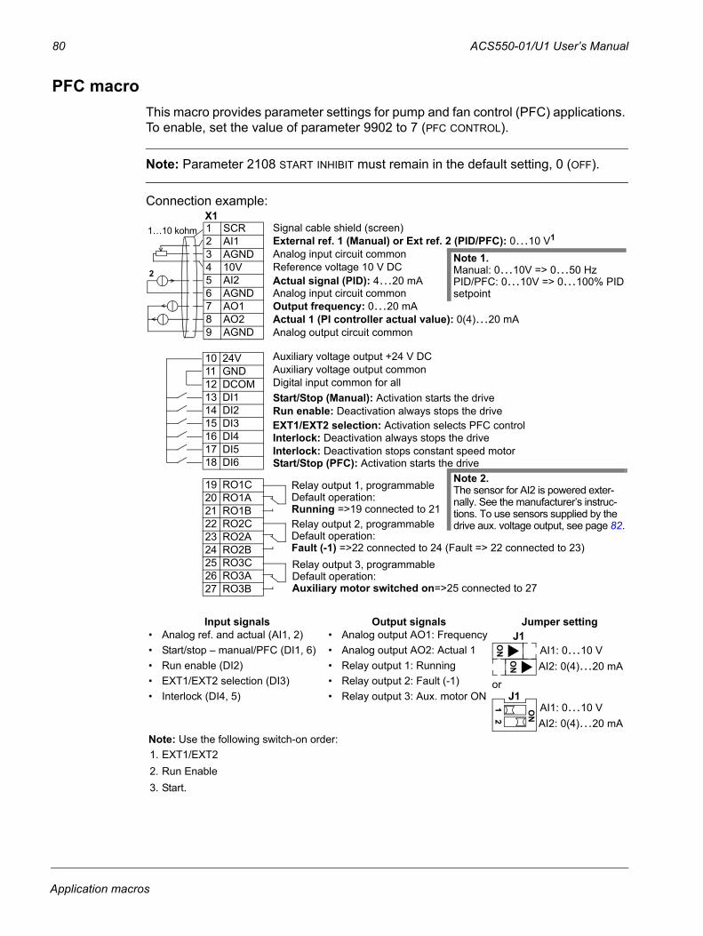
80 ACS550-01/U1 User’s Manual
PFC macroThis macro provides parameter settings for pump and fan control (PFC) applications. To enable, set the value of parameter 9902 to 7 (PFC CONTROL).
Note: Parameter 2108 START INHIBIT must remain in the default setting, 0 (OFF).
Connection example:
Input signals Output signals Jumper setting• Analog ref. and actual (AI1, 2)• Start/stop – manual/PFC (DI1, 6)• Run enable (DI2)• EXT1/EXT2 selection (DI3)• Interlock (DI4, 5)
• Analog output AO1: Frequency• Analog output AO2: Actual 1• Relay output 1: Running • Relay output 2: Fault (-1) • Relay output 3: Aux. motor ON
or
Note: Use the following switch-on order:1. EXT1/EXT22. Run Enable3. Start.
EXT1/EXT2 selection: Activation selects PFC control
1 SCR2 AI13 AGND4 10V5 AI26 AGND7 AO18 AO29 AGND
10 24V11 GND12 DCOM13 DI114 DI215 DI316 DI417 DI518 DI6
19 RO1C20 RO1A21 RO1B22 RO2C23 RO2A24 RO2B25 RO3C26 RO3A27 RO3B
Start/Stop (Manual): Activation starts the drive
Start/Stop (PFC): Activation starts the drive
Run enable: Deactivation always stops the drive
External ref. 1 (Manual) or Ext ref. 2 (PID/PFC): 0…10 V1
Reference voltage 10 V DC
Output frequency: 0…20 mAActual 1 (PI controller actual value): 0(4)…20 mA
Analog input circuit common
Analog output circuit common
Auxiliary voltage output +24 V DCAuxiliary voltage output commonDigital input common for all
Signal cable shield (screen)
Analog input circuit common Actual signal (PID): 4…20 mA
Interlock: Deactivation always stops the driveInterlock: Deactivation stops constant speed motor
Note 1. Manual: 0…10V => 0…50 HzPID/PFC: 0…10V => 0…100% PID setpoint
Relay output 1, programmableDefault operation:
Relay output 2, programmableDefault operation:
Relay output 3, programmableDefault operation:
Running =>19 connected to 21
Fault (-1) =>22 connected to 24 (Fault => 22 connected to 23)
Auxiliary motor switched on=>25 connected to 27
2
Note 2.The sensor for AI2 is powered exter-nally. See the manufacturer’s instruc-tions. To use sensors supplied by the drive aux. voltage output, see page 82.
X11…10 kohm
J1AI1: 0…10 VAI2: 0(4)…20 mA
ON
ON
AI1: 0…10 VAI2: 0(4)…20 mA
ON
12
J1
Application macros
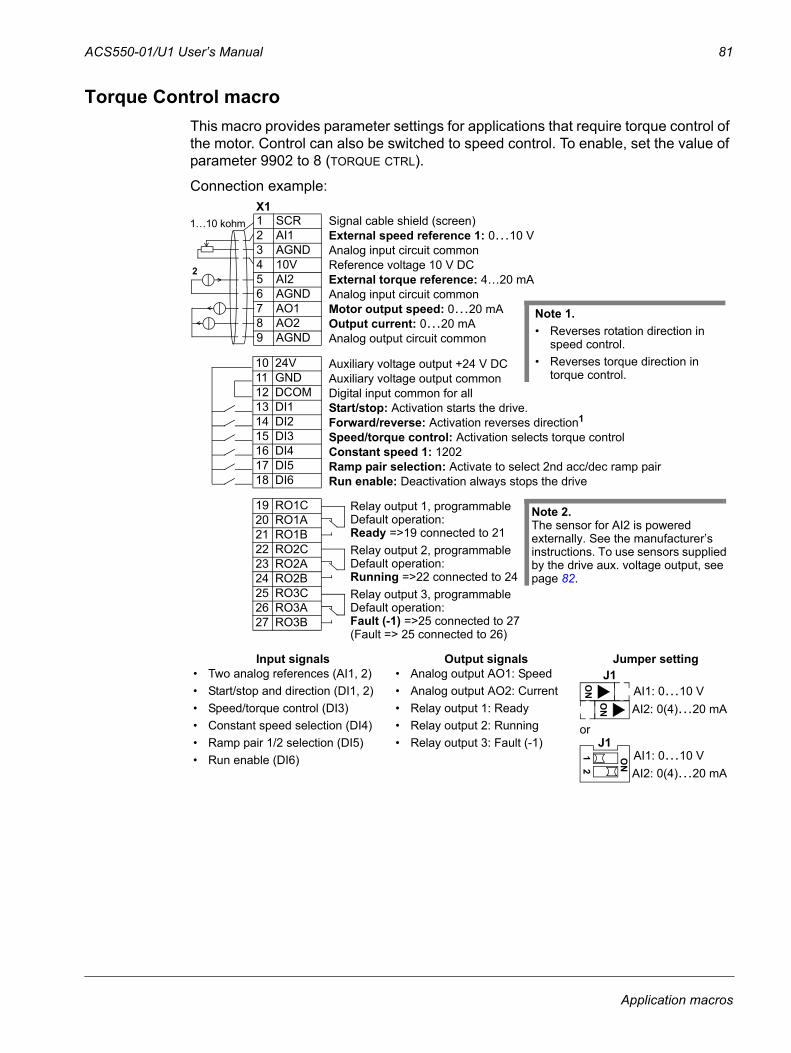
ACS550-01/U1 User’s Manual 81
Torque Control macroThis macro provides parameter settings for applications that require torque control of the motor. Control can also be switched to speed control. To enable, set the value of parameter 9902 to 8 (TORQUE CTRL).
Connection example:
Input signals Output signals Jumper setting• Two analog references (AI1, 2)• Start/stop and direction (DI1, 2)• Speed/torque control (DI3)• Constant speed selection (DI4)• Ramp pair 1/2 selection (DI5)• Run enable (DI6)
• Analog output AO1: Speed• Analog output AO2: Current• Relay output 1: Ready• Relay output 2: Running• Relay output 3: Fault (-1)
or
1 SCR2 AI13 AGND4 10V5 AI26 AGND7 AO18 AO29 AGND
10 24V11 GND12 DCOM13 DI114 DI215 DI316 DI417 DI518 DI6
19 RO1C20 RO1A21 RO1B22 RO2C23 RO2A24 RO2B25 RO3C26 RO3A27 RO3B
External speed reference 1: 0…10 V
Reference voltage 10 V DC
Motor output speed: 0…20 mA
Speed/torque control: Activation selects torque control Constant speed 1: 1202
Relay output 1, programmableDefault operation:
Relay output 2, programmableDefault operation:
Relay output 3, programmableDefault operation:
Output current: 0…20 mA
Ready =>19 connected to 21
Running =>22 connected to 24
Fault (-1) =>25 connected to 27
Analog input circuit common
External torque reference: 4…20 mA
Analog output circuit common
Auxiliary voltage output +24 V DCAuxiliary voltage output commonDigital input common for all
Signal cable shield (screen)
Analog input circuit common Note 1. • Reverses rotation direction in
speed control.• Reverses torque direction in
torque control.
Start/stop: Activation starts the drive.Forward/reverse: Activation reverses direction1
Ramp pair selection: Activate to select 2nd acc/dec ramp pair Run enable: Deactivation always stops the drive
(Fault => 25 connected to 26)
Note 2. The sensor for AI2 is powered externally. See the manufacturer’s instructions. To use sensors supplied by the drive aux. voltage output, see page 82.
2
X11…10 kohm
J1AI1: 0…10 VAI2: 0(4)…20 mA
ON
ON
AI1: 0…10 VAI2: 0(4)…20 mA
ON
12
J1
Application macros
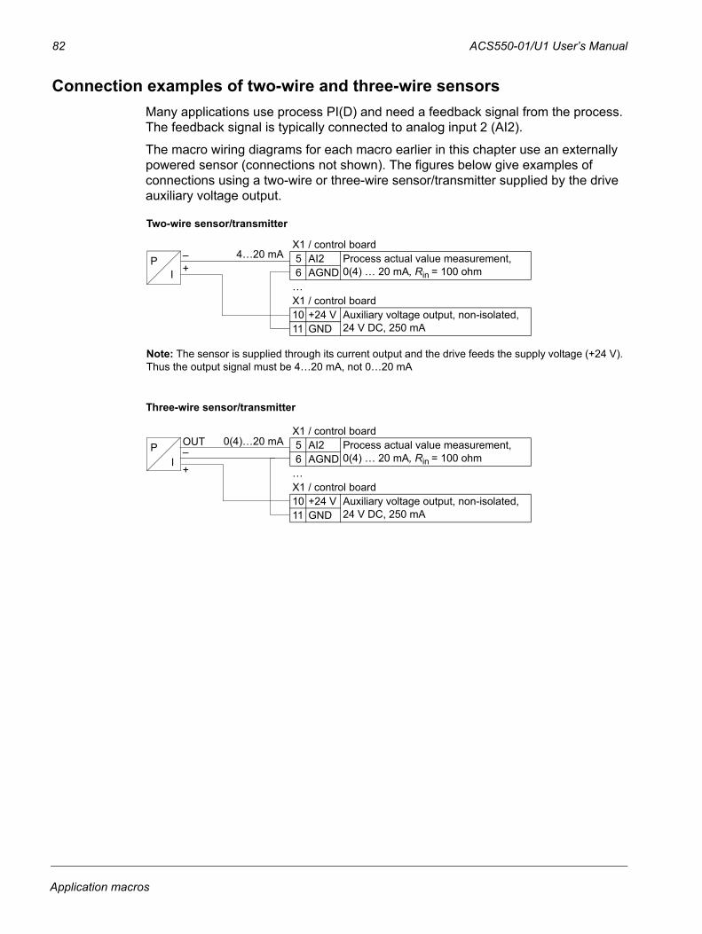
82 ACS550-01/U1 User’s Manual
Connection examples of two-wire and three-wire sensorsMany applications use process PI(D) and need a feedback signal from the process. The feedback signal is typically connected to analog input 2 (AI2).
The macro wiring diagrams for each macro earlier in this chapter use an externally powered sensor (connections not shown). The figures below give examples of connections using a two-wire or three-wire sensor/transmitter supplied by the drive auxiliary voltage output.
X1 / control board5 AI2 Process actual value measurement,
0(4) … 20 mA, Rin = 100 ohm6 AGND…X1 / control board10 +24 V Auxiliary voltage output, non-isolated,
24 V DC, 250 mA11 GND
PI
4…20 mA
X1 / control board5 AI2 Process actual value measurement,
0(4) … 20 mA, Rin = 100 ohm6 AGND…X1 / control board10 +24 V Auxiliary voltage output, non-isolated,
24 V DC, 250 mA11 GND
P 0(4)…20 mA
I
Two-wire sensor/transmitter
Three-wire sensor/transmitter
OUT
–+
–
+
Note: The sensor is supplied through its current output and the drive feeds the supply voltage (+24 V).Thus the output signal must be 4…20 mA, not 0…20 mA
Application macros
ACS550-01/U1 User’s Manual 83
User parameter setsIn addition to the standard application macros, it is possible to save two user parameter sets into the permanent memory and load them at a later time. A user parameter set consists of the user parameter settings, including Group 99: START-UP DATA, and the results of the motor identification. The panel reference is also saved if the user parameter set is saved and loaded in local control. The remote control setting is saved into the user parameter set, but the local control setting is not.
The steps below show how to save and load User Parameter Set 1. The procedure for User Parameter Set 2 is identical, only the parameter 9902 values are different.
To save User Parameter Set 1:
• Adjust the parameters. Perform the motor identification if it is needed in the application but it is not done yet.
• Save the parameter settings and the results of the motor identification to the permanent memory by changing parameter 9902 to -1 (USER S1 SAVE).
• Press (Assistant Control Panel) or (Basic Control Panel).
To load User Parameter Set 1:
• Change parameter 9902 to 0 (USER S1 LOAD).
• Press (Assistant Control Panel) or (Basic Control Panel) to load.
The user parameter set can also be switched through digital inputs (see parameter 1605).
Note: Loading the user parameter set restores the parameter settings including Group 99: START-UP DATA and the results of the motor identification. Check that the settings correspond to the motor used.
Hint: The user can for example switch the drive between two motors without having to adjust the motor parameters and to repeat the motor identification every time the motor is changed. The user needs only to adjust the settings and perform the motor identification once for each motor and then to save the data as two user parameter sets. When the motor is changed, only the corresponding user parameter set needs to be loaded, and the drive is ready to operate.
SAVE ENTERMENU
SAVE ENTERMENU
Application macros
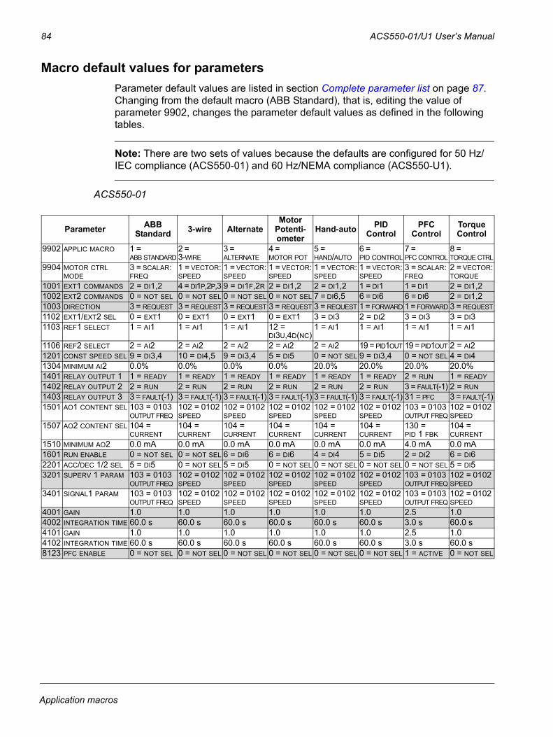
84 ACS550-01/U1 User’s Manual
Macro default values for parametersParameter default values are listed in section Complete parameter list on page 87. Changing from the default macro (ABB Standard), that is, editing the value of parameter 9902, changes the parameter default values as defined in the following tables.
Note: There are two sets of values because the defaults are configured for 50 Hz/IEC compliance (ACS550-01) and 60 Hz/NEMA compliance (ACS550-U1).
ACS550-01
Parameter ABB Standard 3-wire Alternate
Motor Potenti-ometer
Hand-auto PID Control
PFC Control
Torque Control
9902 APPLIC MACRO 1 = ABB STANDARD
2 = 3-WIRE
3 = ALTERNATE
4 = MOTOR POT
5 = HAND/AUTO
6 = PID CONTROL
7 = PFC CONTROL
8 = TORQUE CTRL
9904 MOTOR CTRL MODE
3 = SCALAR:FREQ
1 = VECTOR:SPEED
1 = VECTOR:SPEED
1 = VECTOR:SPEED
1 = VECTOR:SPEED
1 = VECTOR:SPEED
3 = SCALAR:FREQ
2 = VECTOR:TORQUE
1001 EXT1 COMMANDS 2 = DI1,2 4 = DI1P,2P,3 9 = DI1F,2R 2 = DI1,2 2 = DI1,2 1 = DI1 1 = DI1 2 = DI1,21002 EXT2 COMMANDS 0 = NOT SEL 0 = NOT SEL 0 = NOT SEL 0 = NOT SEL 7 = DI6,5 6 = DI6 6 = DI6 2 = DI1,21003 DIRECTION 3 = REQUEST 3 = REQUEST 3 = REQUEST 3 = REQUEST 3 = REQUEST 1 = FORWARD 1 = FORWARD 3 = REQUEST1102 EXT1/EXT2 SEL 0 = EXT1 0 = EXT1 0 = EXT1 0 = EXT1 3 = DI3 2 = DI2 3 = DI3 3 = DI31103 REF1 SELECT 1 = AI1 1 = AI1 1 = AI1 12 =
DI3U,4D(NC)1 = AI1 1 = AI1 1 = AI1 1 = AI1
1106 REF2 SELECT 2 = AI2 2 = AI2 2 = AI2 2 = AI2 2 = AI2 19 = PID1OUT 19 = PID1OUT 2 = AI21201 CONST SPEED SEL 9 = DI3,4 10 = DI4,5 9 = DI3,4 5 = DI5 0 = NOT SEL 9 = DI3,4 0 = NOT SEL 4 = DI41304 MINIMUM AI2 0.0% 0.0% 0.0% 0.0% 20.0% 20.0% 20.0% 20.0%1401 RELAY OUTPUT 1 1 = READY 1 = READY 1 = READY 1 = READY 1 = READY 1 = READY 2 = RUN 1 = READY1402 RELAY OUTPUT 2 2 = RUN 2 = RUN 2 = RUN 2 = RUN 2 = RUN 2 = RUN 3 = FAULT(-1) 2 = RUN1403 RELAY OUTPUT 3 3 = FAULT(-1) 3 = FAULT(-1) 3 = FAULT(-1) 3 = FAULT(-1) 3 = FAULT(-1) 3 = FAULT(-1) 31 = PFC 3 = FAULT(-1)1501 AO1 CONTENT SEL 103 = 0103
OUTPUT FREQ102 = 0102 SPEED
102 = 0102 SPEED
102 = 0102 SPEED
102 = 0102 SPEED
102 = 0102 SPEED
103 = 0103 OUTPUT FREQ
102 = 0102 SPEED
1507 AO2 CONTENT SEL 104 = CURRENT
104 = CURRENT
104 = CURRENT
104 = CURRENT
104 = CURRENT
104 = CURRENT
130 = PID 1 FBK
104 = CURRENT
1510 MINIMUM AO2 0.0 mA 0.0 mA 0.0 mA 0.0 mA 0.0 mA 0.0 mA 4.0 mA 0.0 mA1601 RUN ENABLE 0 = NOT SEL 0 = NOT SEL 6 = DI6 6 = DI6 4 = DI4 5 = DI5 2 = DI2 6 = DI62201 ACC/DEC 1/2 SEL 5 = DI5 0 = NOT SEL 5 = DI5 0 = NOT SEL 0 = NOT SEL 0 = NOT SEL 0 = NOT SEL 5 = DI53201 SUPERV 1 PARAM 103 = 0103
OUTPUT FREQ102 = 0102 SPEED
102 = 0102 SPEED
102 = 0102 SPEED
102 = 0102 SPEED
102 = 0102 SPEED
103 = 0103 OUTPUT FREQ
102 = 0102 SPEED
3401 SIGNAL1 PARAM 103 = 0103 OUTPUT FREQ
102 = 0102 SPEED
102 = 0102 SPEED
102 = 0102 SPEED
102 = 0102 SPEED
102 = 0102 SPEED
103 = 0103 OUTPUT FREQ
102 = 0102 SPEED
4001 GAIN 1.0 1.0 1.0 1.0 1.0 1.0 2.5 1.04002 INTEGRATION TIME 60.0 s 60.0 s 60.0 s 60.0 s 60.0 s 60.0 s 3.0 s 60.0 s4101 GAIN 1.0 1.0 1.0 1.0 1.0 1.0 2.5 1.04102 INTEGRATION TIME 60.0 s 60.0 s 60.0 s 60.0 s 60.0 s 60.0 s 3.0 s 60.0 s8123 PFC ENABLE 0 = NOT SEL 0 = NOT SEL 0 = NOT SEL 0 = NOT SEL 0 = NOT SEL 0 = NOT SEL 1 = ACTIVE 0 = NOT SEL
Application macros
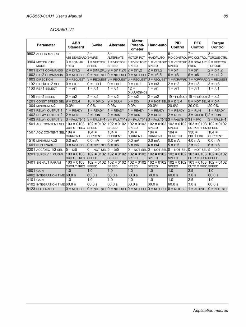
ACS550-01/U1 User’s Manual 85
ACS550-U1
Parameter ABB Standard 3-wire Alternate
Motor Potenti-ometer
Hand-auto PID Control
PFC Control
Torque Control
9902 APPLIC MACRO 1 = ABB STANDARD
2 = 3-WIRE
3 = ALTERNATE
4 = MOTOR POT
5 = HAND/AUTO
6 = PID CONTROL
7 = PFC CONTROL
8 = TORQUE CTRL
9904 MOTOR CTRL MODE
3 = SCALAR:FREQ
1 = VECTOR:SPEED
1 = VECTOR:SPEED
1 = VECTOR:SPEED
1 = VECTOR:SPEED
1 = VECTOR:SPEED
3 = SCALAR:FREQ
2 = VECTOR:TORQUE
1001 EXT1 COMMANDS 2 = DI1,2 4 = DI1P,2P,3 9 = DI1F,2R 2 = DI1,2 2 = DI1,2 1 = DI1 1 = DI1 2 = DI1,21002 EXT2 COMMANDS 0 = NOT SEL 0 = NOT SEL 0 = NOT SEL 0 = NOT SEL 7 = DI6,5 6 = DI6 6 = DI6 2 = DI1,21003 DIRECTION 3 = REQUEST 3 = REQUEST 3 = REQUEST 3 = REQUEST 3 = REQUEST 1 = FORWARD 1 = FORWARD 3 = REQUEST1102 EXT1/EXT2 SEL 0 = EXT1 0 = EXT1 0 = EXT1 0 = EXT1 3 = DI3 2 = DI2 3 = DI3 3 = DI31103 REF1 SELECT 1 = AI1 1 = AI1 1 = AI1 12 =
DI3U,4D(NC)1 = AI1 1 = AI1 1 = AI1 1 = AI1
1106 REF2 SELECT 2 = AI2 2 = AI2 2 = AI2 2 = AI2 2 = AI2 19 = PID1OUT 19 = PID1OUT 2 = AI21201 CONST SPEED SEL 9 = DI3,4 10 = DI4,5 9 = DI3,4 5 = DI5 0 = NOT SEL 9 = DI3,4 0 = NOT SEL 4 = DI41304 MINIMUM AI2 0.0% 0.0% 0.0% 0.0% 20.0% 20.0% 20.0% 20.0%1401 RELAY OUTPUT 1 1 = READY 1 = READY 1 = READY 1 = READY 1 = READY 1 = READY 2 = RUN 1 = READY1402 RELAY OUTPUT 2 2 = RUN 2 = RUN 2 = RUN 2 = RUN 2 = RUN 2 = RUN 3 = FAULT(-1) 2 = RUN1403 RELAY OUTPUT 3 3 = FAULT(-1) 3 = FAULT(-1) 3 = FAULT(-1) 3 = FAULT(-1) 3 = FAULT(-1) 3 = FAULT(-1) 31 = PFC 3 = FAULT(-1)1501 AO1 CONTENT SEL 103 = 0103
OUTPUT FREQ102 = 0102 SPEED
102 = 0102 SPEED
102 = 0102 SPEED
102 = 0102 SPEED
102 = 0102 SPEED
103 = 0103 OUTPUT FREQ
102 = 0102 SPEED
1507 AO2 CONTENT SEL 104 = CURRENT
104 = CURRENT
104 = CURRENT
104 = CURRENT
104 = CURRENT
104 = CURRENT
130 = PID 1 FBK
104 = CURRENT
1510 MINIMUM AO2 0.0 mA 0.0 mA 0.0 mA 0.0 mA 0.0 mA 0.0 mA 4.0 mA 0.0 mA1601 RUN ENABLE 0 = NOT SEL 0 = NOT SEL 6 = DI6 6 = DI6 4 = DI4 5 = DI5 2 = DI2 6 = DI62201 ACC/DEC 1/2 SEL 5 = DI5 0 = NOT SEL 5 = DI5 0 = NOT SEL 0 = NOT SEL 0 = NOT SEL 0 = NOT SEL 5 = DI53201 SUPERV 1 PARAM 103 = 0103
OUTPUT FREQ102 = 0102 SPEED
102 = 0102 SPEED
102 = 0102 SPEED
102 = 0102 SPEED
102 = 0102 SPEED
103 = 0103 OUTPUT FREQ
102 = 0102 SPEED
3401 SIGNAL1 PARAM 103 = 0103 OUTPUT FREQ
102 = 0102 SPEED
102 = 0102 SPEED
102 = 0102 SPEED
102 = 0102 SPEED
102 = 0102 SPEED
103 = 0103 OUTPUT FREQ
102 = 0102 SPEED
4001 GAIN 1.0 1.0 1.0 1.0 1.0 1.0 2.5 1.04002 INTEGRATION TIME 60.0 s 60.0 s 60.0 s 60.0 s 60.0 s 60.0 s 3.0 s 60.0 s4101 GAIN 1.0 1.0 1.0 1.0 1.0 1.0 2.5 1.04102 INTEGRATION TIME 60.0 s 60.0 s 60.0 s 60.0 s 60.0 s 60.0 s 3.0 s 60.0 s8123 PFC ENABLE 0 = NOT SEL 0 = NOT SEL 0 = NOT SEL 0 = NOT SEL 0 = NOT SEL 0 = NOT SEL 1 = ACTIVE 0 = NOT SEL
Application macros

86 ACS550-01/U1 User’s Manual
Application macros
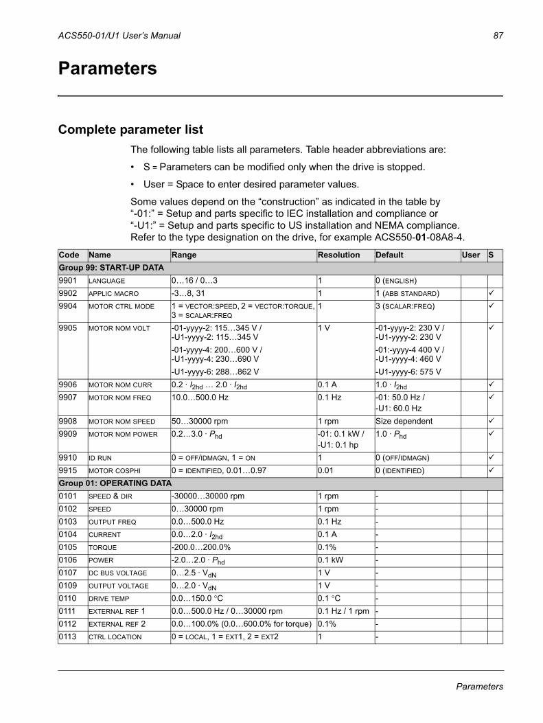
ACS550-01/U1 User’s Manual 87
Parameters
Complete parameter listThe following table lists all parameters. Table header abbreviations are:
• S = Parameters can be modified only when the drive is stopped.
• User = Space to enter desired parameter values.
Some values depend on the “construction” as indicated in the table by “-01:” = Setup and parts specific to IEC installation and compliance or “-U1:” = Setup and parts specific to US installation and NEMA compliance. Refer to the type designation on the drive, for example ACS550-01-08A8-4.
Code Name Range Resolution Default User SGroup 99: START-UP DATA9901 LANGUAGE 0…16 / 0…3 1 0 (ENGLISH)9902 APPLIC MACRO -3…8, 31 1 1 (ABB STANDARD)9904 MOTOR CTRL MODE 1 = VECTOR:SPEED, 2 = VECTOR:TORQUE,
3 = SCALAR:FREQ1 3 (SCALAR:FREQ)
9905 MOTOR NOM VOLT -01-yyyy-2: 115…345 V /-U1-yyyy-2: 115…345 V
1 V -01-yyyy-2: 230 V /-U1-yyyy-2: 230 V
-01-yyyy-4: 200…600 V /-U1-yyyy-4: 230…690 V
-01:-yyyy-4 400 V / -U1-yyyy-4: 460 V
-U1-yyyy-6: 288…862 V -U1-yyyy-6: 575 V9906 MOTOR NOM CURR 0.2 · I2hd … 2.0 · I2hd 0.1 A 1.0 · I2hd9907 MOTOR NOM FREQ 10.0…500.0 Hz 0.1 Hz -01: 50.0 Hz /
-U1: 60.0 Hz9908 MOTOR NOM SPEED 50…30000 rpm 1 rpm Size dependent9909 MOTOR NOM POWER 0.2…3.0 · Phd -01: 0.1 kW /
-U1: 0.1 hp1.0 · Phd
9910 ID RUN 0 = OFF/IDMAGN, 1 = ON 1 0 (OFF/IDMAGN)9915 MOTOR COSPHI 0 = IDENTIFIED, 0.01…0.97 0.01 0 (IDENTIFIED)Group 01: OPERATING DATA0101 SPEED & DIR -30000…30000 rpm 1 rpm -0102 SPEED 0…30000 rpm 1 rpm -0103 OUTPUT FREQ 0.0…500.0 Hz 0.1 Hz -0104 CURRENT 0.0…2.0 · I2hd 0.1 A -0105 TORQUE -200.0…200.0% 0.1% -0106 POWER -2.0…2.0 · Phd 0.1 kW -0107 DC BUS VOLTAGE 0…2.5 · VdN 1 V -0109 OUTPUT VOLTAGE 0…2.0 · VdN 1 V -0110 DRIVE TEMP 0.0…150.0 °C 0.1 °C -0111 EXTERNAL REF 1 0.0…500.0 Hz / 0…30000 rpm 0.1 Hz / 1 rpm -0112 EXTERNAL REF 2 0.0…100.0% (0.0…600.0% for torque) 0.1% -0113 CTRL LOCATION 0 = LOCAL, 1 = EXT1, 2 = EXT2 1 -
Parameters
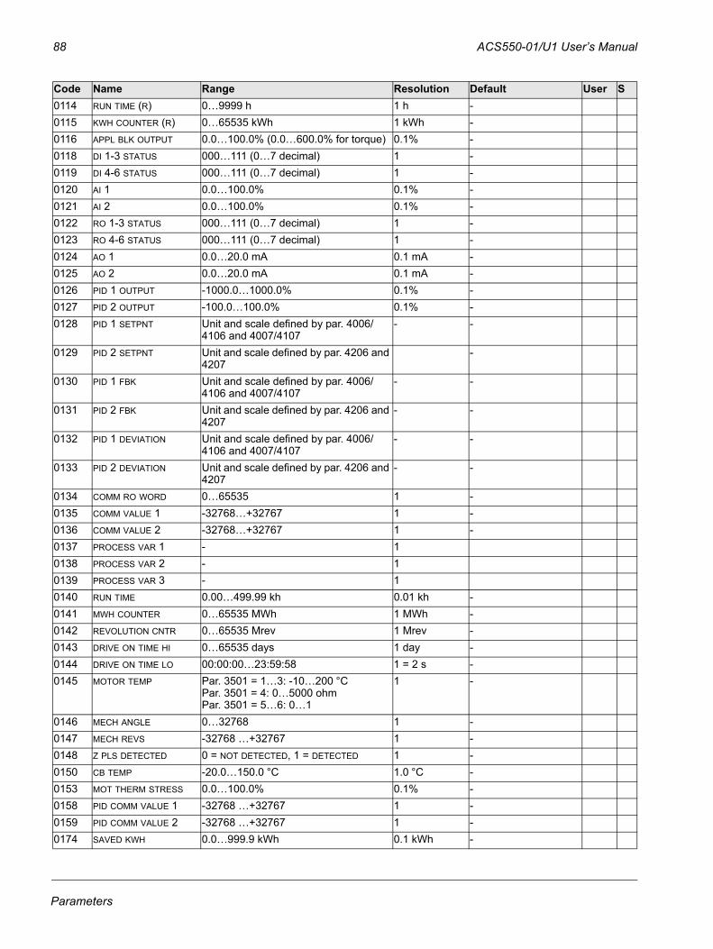
88 ACS550-01/U1 User’s Manual
0114 RUN TIME (R) 0…9999 h 1 h -0115 KWH COUNTER (R) 0…65535 kWh 1 kWh -0116 APPL BLK OUTPUT 0.0…100.0% (0.0…600.0% for torque) 0.1% -0118 DI 1-3 STATUS 000…111 (0…7 decimal) 1 -0119 DI 4-6 STATUS 000…111 (0…7 decimal) 1 -0120 AI 1 0.0…100.0% 0.1% -0121 AI 2 0.0…100.0% 0.1% -0122 RO 1-3 STATUS 000…111 (0…7 decimal) 1 -0123 RO 4-6 STATUS 000…111 (0…7 decimal) 1 -0124 AO 1 0.0…20.0 mA 0.1 mA -0125 AO 2 0.0…20.0 mA 0.1 mA -0126 PID 1 OUTPUT -1000.0…1000.0% 0.1% -0127 PID 2 OUTPUT -100.0…100.0% 0.1% -0128 PID 1 SETPNT Unit and scale defined by par. 4006/
4106 and 4007/4107- -
0129 PID 2 SETPNT Unit and scale defined by par. 4206 and 4207
-
0130 PID 1 FBK Unit and scale defined by par. 4006/4106 and 4007/4107
- -
0131 PID 2 FBK Unit and scale defined by par. 4206 and 4207
- -
0132 PID 1 DEVIATION Unit and scale defined by par. 4006/4106 and 4007/4107
- -
0133 PID 2 DEVIATION Unit and scale defined by par. 4206 and 4207
- -
0134 COMM RO WORD 0…65535 1 -0135 COMM VALUE 1 -32768…+32767 1 -0136 COMM VALUE 2 -32768…+32767 1 -0137 PROCESS VAR 1 - 10138 PROCESS VAR 2 - 10139 PROCESS VAR 3 - 10140 RUN TIME 0.00…499.99 kh 0.01 kh -0141 MWH COUNTER 0…65535 MWh 1 MWh -0142 REVOLUTION CNTR 0…65535 Mrev 1 Mrev -0143 DRIVE ON TIME HI 0…65535 days 1 day -0144 DRIVE ON TIME LO 00:00:00…23:59:58 1 = 2 s -0145 MOTOR TEMP Par. 3501 = 1…3: -10…200 °C
Par. 3501 = 4: 0…5000 ohmPar. 3501 = 5…6: 0…1
1 -
0146 MECH ANGLE 0…32768 1 -0147 MECH REVS -32768 …+32767 1 -0148 Z PLS DETECTED 0 = NOT DETECTED, 1 = DETECTED 1 -0150 CB TEMP -20.0…150.0 °C 1.0 °C -0153 MOT THERM STRESS 0.0…100.0% 0.1% -0158 PID COMM VALUE 1 -32768 …+32767 1 -0159 PID COMM VALUE 2 -32768 …+32767 1 -0174 SAVED KWH 0.0…999.9 kWh 0.1 kWh -
Code Name Range Resolution Default User S
Parameters
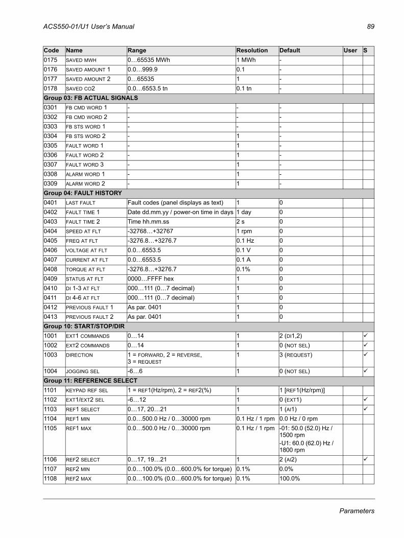
ACS550-01/U1 User’s Manual 89
0175 SAVED MWH 0…65535 MWh 1 MWh -0176 SAVED AMOUNT 1 0.0…999.9 0.1 -0177 SAVED AMOUNT 2 0…65535 1 -0178 SAVED CO2 0.0…6553.5 tn 0.1 tn -Group 03: FB ACTUAL SIGNALS0301 FB CMD WORD 1 - - -0302 FB CMD WORD 2 - - -0303 FB STS WORD 1 - - -0304 FB STS WORD 2 - 1 -0305 FAULT WORD 1 - 1 -0306 FAULT WORD 2 - 1 -0307 FAULT WORD 3 - 1 -0308 ALARM WORD 1 - 1 -0309 ALARM WORD 2 - 1 -Group 04: FAULT HISTORY0401 LAST FAULT Fault codes (panel displays as text) 1 00402 FAULT TIME 1 Date dd.mm.yy / power-on time in days 1 day 00403 FAULT TIME 2 Time hh.mm.ss 2 s 00404 SPEED AT FLT -32768…+32767 1 rpm 00405 FREQ AT FLT -3276.8…+3276.7 0.1 Hz 00406 VOLTAGE AT FLT 0.0…6553.5 0.1 V 00407 CURRENT AT FLT 0.0…6553.5 0.1 A 00408 TORQUE AT FLT -3276.8…+3276.7 0.1% 00409 STATUS AT FLT 0000…FFFF hex 1 00410 DI 1-3 AT FLT 000…111 (0…7 decimal) 1 00411 DI 4-6 AT FLT 000…111 (0…7 decimal) 1 00412 PREVIOUS FAULT 1 As par. 0401 1 00413 PREVIOUS FAULT 2 As par. 0401 1 0Group 10: START/STOP/DIR1001 EXT1 COMMANDS 0…14 1 2 (DI1,2)1002 EXT2 COMMANDS 0…14 1 0 (NOT SEL)1003 DIRECTION 1 = FORWARD, 2 = REVERSE,
3 = REQUEST1 3 (REQUEST)
1004 JOGGING SEL -6…6 1 0 (NOT SEL)Group 11: REFERENCE SELECT1101 KEYPAD REF SEL 1 = REF1(Hz/rpm), 2 = REF2(%) 1 1 [REF1(Hz/rpm)]1102 EXT1/EXT2 SEL -6…12 1 0 (EXT1)1103 REF1 SELECT 0…17, 20…21 1 1 (AI1)1104 REF1 MIN 0.0…500.0 Hz / 0…30000 rpm 0.1 Hz / 1 rpm 0.0 Hz / 0 rpm1105 REF1 MAX 0.0…500.0 Hz / 0…30000 rpm 0.1 Hz / 1 rpm -01: 50.0 (52.0) Hz /
1500 rpm-U1: 60.0 (62.0) Hz / 1800 rpm
1106 REF2 SELECT 0…17, 19…21 1 2 (AI2)1107 REF2 MIN 0.0…100.0% (0.0…600.0% for torque) 0.1% 0.0%1108 REF2 MAX 0.0…100.0% (0.0…600.0% for torque) 0.1% 100.0%
Code Name Range Resolution Default User S
Parameters
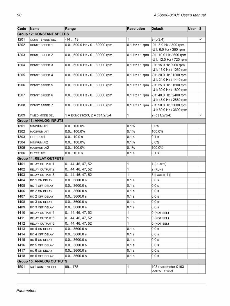
90 ACS550-01/U1 User’s Manual
Group 12: CONSTANT SPEEDS1201 CONST SPEED SEL -14 …19 1 9 (DI3,4)1202 CONST SPEED 1 0.0…500.0 Hz / 0…30000 rpm 0.1 Hz / 1 rpm -01: 5.0 Hz / 300 rpm
-U1: 6.0 Hz / 360 rpm1203 CONST SPEED 2 0.0…500.0 Hz / 0…30000 rpm 0.1 Hz / 1 rpm -01: 10.0 Hz / 600 rpm
-U1: 12.0 Hz / 720 rpm1204 CONST SPEED 3 0.0…500.0 Hz / 0…30000 rpm 0.1 Hz / 1 rpm -01: 15.0 Hz / 900 rpm
-U1: 18.0 Hz / 1080 rpm1205 CONST SPEED 4 0.0…500.0 Hz / 0…30000 rpm 0.1 Hz / 1 rpm -01: 20.0 Hz / 1200 rpm
-U1: 24.0 Hz / 1440 rpm1206 CONST SPEED 5 0.0…500.0 Hz / 0…30000 rpm 0.1 Hz / 1 rpm -01: 25.0 Hz / 1500 rpm
-U1: 30.0 Hz / 1800 rpm1207 CONST SPEED 6 0.0…500.0 Hz / 0…30000 rpm 0.1 Hz / 1 rpm -01: 40.0 Hz / 2400 rpm
-U1: 48.0 Hz / 2880 rpm1208 CONST SPEED 7 0.0…500.0 Hz / 0…30000 rpm 0.1 Hz / 1 rpm -01: 50.0 Hz / 3000 rpm
-U1: 60.0 Hz / 3600 rpm1209 TIMED MODE SEL 1 = EXT/CS1/2/3, 2 = CS1/2/3/4 1 2 (CS1/2/3/4)Group 13: ANALOG INPUTS1301 MINIMUM AI1 0.0…100.0% 0.1% 0.0%1302 MAXIMUM AI1 0.0…100.0% 0.1% 100.0%1303 FILTER AI1 0.0…10.0 s 0.1 s 0.1 s1304 MINIMUM AI2 0.0…100.0% 0.1% 0.0%1305 MAXIMUM AI2 0.0…100.0% 0.1% 100.0%1306 FILTER AI2 0.0…10.0 s 0.1 s 0.1 sGroup 14: RELAY OUTPUTS1401 RELAY OUTPUT 1 0…44, 46, 47, 52 1 1 (READY)1402 RELAY OUTPUT 2 0…44, 46, 47, 52 1 2 (RUN)1403 RELAY OUTPUT 3 0…44, 46, 47, 52 1 3 [FAULT(-1)]1404 RO 1 ON DELAY 0.0…3600.0 s 0.1 s 0.0 s1405 RO 1 OFF DELAY 0.0…3600.0 s 0.1 s 0.0 s1406 RO 2 ON DELAY 0.0…3600.0 s 0.1 s 0.0 s1407 RO 2 OFF DELAY 0.0…3600.0 s 0.1 s 0.0 s1408 RO 3 ON DELAY 0.0…3600.0 s 0.1 s 0.0 s1409 RO 3 OFF DELAY 0.0…3600.0 s 0.1 s 0.0 s1410 RELAY OUTPUT 4 0…44, 46, 47, 52 1 0 (NOT SEL)1411 RELAY OUTPUT 5 0…44, 46, 47, 52 1 0 (NOT SEL)1412 RELAY OUTPUT 6 0…44, 46, 47, 52 1 0 (NOT SEL)1413 RO 4 ON DELAY 0.0…3600.0 s 0.1 s 0.0 s1414 RO 4 OFF DELAY 0.0…3600.0 s 0.1 s 0.0 s1415 RO 5 ON DELAY 0.0…3600.0 s 0.1 s 0.0 s1416 RO 5 OFF DELAY 0.0…3600.0 s 0.1 s 0.0 s1417 RO 6 ON DELAY 0.0…3600.0 s 0.1 s 0.0 s1418 RO 6 OFF DELAY 0.0…3600.0 s 0.1 s 0.0 sGroup 15: ANALOG OUTPUTS1501 AO1 CONTENT SEL 99…178 1 103 (parameter 0103
OUTPUT FREQ)
Code Name Range Resolution Default User S
Parameters
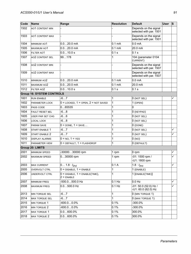
ACS550-01/U1 User’s Manual 91
1502 AO1 CONTENT MIN - - Depends on the signal selected with par. 1501
1503 AO1 CONTENT MAX - - Depends on the signal selected with par. 1501
1504 MINIMUM AO1 0.0…20.0 mA 0.1 mA 0.0 mA1505 MAXIMUM AO1 0.0…20.0 mA 0.1 mA 20.0 mA1506 FILTER AO1 0.0…10.0 s 0.1 s 0.1 s1507 AO2 CONTENT SEL 99…178 1 104 (parameter 0104
CURRENT)1508 AO2 CONTENT MIN - - Depends on the signal
selected with par. 15071509 AO2 CONTENT MAX - - Depends on the signal
selected with par. 15071510 MINIMUM AO2 0.0…20.0 mA 0.1 mA 0.0 mA1511 MAXIMUM AO2 0.0…20.0 mA 0.1 mA 20.0 mA1512 FILTER AO2 0.0…10.0 s 0.1 s 0.1 sGroup 16: SYSTEM CONTROLS1601 RUN ENABLE -6…7 1 0 (NOT SEL)1602 PARAMETER LOCK 0 = LOCKED, 1 = OPEN, 2 = NOT SAVED 1 1 (OPEN)1603 PASS CODE 0…65535 1 01604 FAULT RESET sEL -6…8 1 0 (KEYPAD)1605 USER PAR SET CHG -6…6 1 0 (NOT SEL)1606 LOCAL LOCK -6…8 1 0 (NOT SEL)1607 PARAM SAVE 0 = DONE, 1 = SAVE… 1 0 (DONE)1608 START ENABLE 1 -6…7 1 0 (NOT SEL)1609 START ENABLE 2 -6…7 1 0 (NOT SEL)1610 DISPLAY ALARMS 0 = NO, 1 = YES 1 0 (NO)1611 PARAMETER VIEW 0 = DEFAULT, 1 = FLASHDROP 1 0 (DEFAULT)Group 20: LIMITS2001 MINIMUM SPEED -30000…30000 rpm 1 rpm 0 rpm2002 MAXIMUM SPEED 0…30000 rpm 1 rpm -01: 1500 rpm /
-U1: 1800 rpm2003 MAX CURRENT 0… 1.8 · I2hd 0.1 A 1.8 · I2hd2005 OVERVOLT CTRL 0 = DISABLE, 1 = ENABLE 1 1 (ENABLE)2006 UNDERVOLT CTRL 0 = DISABLE, 1 = ENABLE(TIME),
2 = ENABLE1 1 [ENABLE(TIME)]
2007 MINIMUM FREQ -500.0…500.0 Hz 0.1 Hz 0.0 Hz2008 MAXIMUM FREQ 0.0…500.0 Hz 0.1 Hz -01: 50.0 (52.0) Hz /
-U1: 60.0 (62.0) Hz2013 MIN TORQUE SEL -6…7 1 0 (MIN TORQUE 1)2014 MAX TORQUE SEL -6…7 1 0 (MAX TORQUE 1)2015 MIN TORQUE 1 -600.0…0.0% 0.1% -300.0%2016 MIN TORQUE 2 -600.0…0.0% 0.1% -300.0%2017 MAX TORQUE 1 0.0…600.0% 0.1% 300.0%2018 MAX TORQUE 2 0.0…600.0% 0.1% 300.0%
Code Name Range Resolution Default User S
Parameters
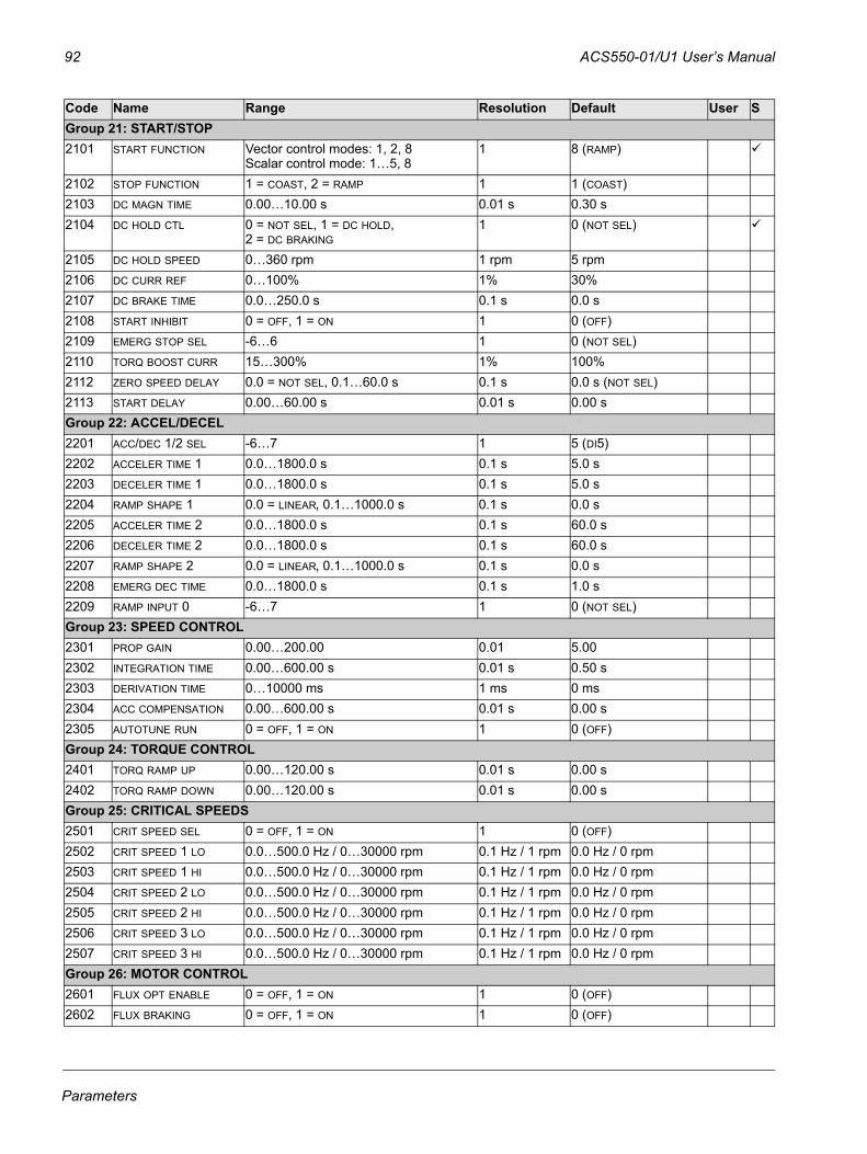
92 ACS550-01/U1 User’s Manual
Group 21: START/STOP2101 START FUNCTION Vector control modes: 1, 2, 8
Scalar control mode: 1…5, 81 8 (RAMP)
2102 STOP FUNCTION 1 = COAST, 2 = RAMP 1 1 (COAST)2103 DC MAGN TIME 0.00…10.00 s 0.01 s 0.30 s2104 DC HOLD CTL 0 = NOT SEL, 1 = DC HOLD,
2 = DC BRAKING1 0 (NOT SEL)
2105 DC HOLD SPEED 0…360 rpm 1 rpm 5 rpm2106 DC CURR REF 0…100% 1% 30%2107 DC BRAKE TIME 0.0…250.0 s 0.1 s 0.0 s2108 START INHIBIT 0 = OFF, 1 = ON 1 0 (OFF)2109 EMERG STOP SEL -6…6 1 0 (NOT SEL)2110 TORQ BOOST CURR 15…300% 1% 100%2112 ZERO SPEED DELAY 0.0 = NOT SEL, 0.1…60.0 s 0.1 s 0.0 s (NOT SEL)2113 START DELAY 0.00…60.00 s 0.01 s 0.00 s Group 22: ACCEL/DECEL2201 ACC/DEC 1/2 SEL -6…7 1 5 (DI5)2202 ACCELER TIME 1 0.0…1800.0 s 0.1 s 5.0 s2203 DECELER TIME 1 0.0…1800.0 s 0.1 s 5.0 s2204 RAMP SHAPE 1 0.0 = LINEAR, 0.1…1000.0 s 0.1 s 0.0 s2205 ACCELER TIME 2 0.0…1800.0 s 0.1 s 60.0 s2206 DECELER TIME 2 0.0…1800.0 s 0.1 s 60.0 s2207 RAMP SHAPE 2 0.0 = LINEAR, 0.1…1000.0 s 0.1 s 0.0 s2208 EMERG DEC TIME 0.0…1800.0 s 0.1 s 1.0 s2209 RAMP INPUT 0 -6…7 1 0 (NOT SEL)Group 23: SPEED CONTROL2301 PROP GAIN 0.00…200.00 0.01 5.002302 INTEGRATION TIME 0.00…600.00 s 0.01 s 0.50 s2303 DERIVATION TIME 0…10000 ms 1 ms 0 ms2304 ACC COMPENSATION 0.00…600.00 s 0.01 s 0.00 s2305 AUTOTUNE RUN 0 = OFF, 1 = ON 1 0 (OFF)Group 24: TORQUE CONTROL2401 TORQ RAMP UP 0.00…120.00 s 0.01 s 0.00 s2402 TORQ RAMP DOWN 0.00…120.00 s 0.01 s 0.00 sGroup 25: CRITICAL SPEEDS2501 CRIT SPEED SEL 0 = OFF, 1 = ON 1 0 (OFF)2502 CRIT SPEED 1 LO 0.0…500.0 Hz / 0…30000 rpm 0.1 Hz / 1 rpm 0.0 Hz / 0 rpm2503 CRIT SPEED 1 HI 0.0…500.0 Hz / 0…30000 rpm 0.1 Hz / 1 rpm 0.0 Hz / 0 rpm2504 CRIT SPEED 2 LO 0.0…500.0 Hz / 0…30000 rpm 0.1 Hz / 1 rpm 0.0 Hz / 0 rpm2505 CRIT SPEED 2 HI 0.0…500.0 Hz / 0…30000 rpm 0.1 Hz / 1 rpm 0.0 Hz / 0 rpm2506 CRIT SPEED 3 LO 0.0…500.0 Hz / 0…30000 rpm 0.1 Hz / 1 rpm 0.0 Hz / 0 rpm2507 CRIT SPEED 3 HI 0.0…500.0 Hz / 0…30000 rpm 0.1 Hz / 1 rpm 0.0 Hz / 0 rpmGroup 26: MOTOR CONTROL2601 FLUX OPT ENABLE 0 = OFF, 1 = ON 1 0 (OFF)2602 FLUX BRAKING 0 = OFF, 1 = ON 1 0 (OFF)
Code Name Range Resolution Default User S
Parameters
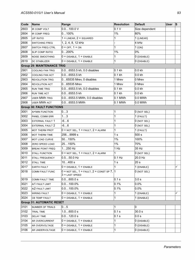
ACS550-01/U1 User’s Manual 93
2603 IR COMP VOLT 0.0…100.0 V 0.1 V Size dependent2604 IR COMP FREQ 0…100% 1% 80%2605 U/F RATIO 1 = LINEAR, 2 = SQUARED 1 1 (LINEAR)2606 SWITCHING FREQ 1, 2, 4, 8, 12 kHz - 4 kHz2607 SWITCH FREQ CTRL 0 = OFF, 1 = ON 1 1 (ON)2608 SLIP COMP RATIO 0…200% 1% 0%2609 NOISE SMOOTHING 0 = DISABLE, 1 = ENABLE 1 0 (DISABLE)2619 DC STABILIZER 0 = DISABLE, 1 = ENABLE 1 0 (DISABLE)Group 29: MAINTENANCE TRIG2901 COOLING FAN TRIG 0.0…6553.5 kh, 0.0 disables 0.1 kh 0.0 kh2902 COOLING FAN ACT 0.0…6553.5 kh 0.1 kh 0.0 kh2903 REVOLUTION TRIG 0…65535 Mrev, 0 disables 1 Mrev 0 Mrev2904 REVOLUTION ACT 0…65535 Mrev 1 Mrev 0 Mrev2905 RUN TIME TRIG 0.0…6553.5 kh, 0.0 disables 0.1 kh 0.0 kh2906 RUN TIME ACT 0.0…6553.5 kh 0.1 kh 0.0 kh2907 USER MWh TRIG 0.0…6553.5 MWh, 0.0 disables 0.1 MWh 0.0 MWh2908 USER MWh ACT 0.0…6553.5 MWh 0.1 MWh 0.0 MWhGroup 30: FAULT FUNCTIONS3001 AI<MIN FUNCTION 0…3 1 0 (NOT SEL)3002 PANEL COMM ERR 1…3 1 1 (FAULT)3003 EXTERNAL FAULT 1 -6…6 1 0 (NOT SEL)3004 EXTERNAL FAULT 2 -6…6 1 0 (NOT SEL)3005 MOT THERM PROT 0 = NOT SEL, 1 = FAULT, 2 = ALARM 1 1 (FAULT)3006 MOT THERM TIME 256…9999 s 1 s 500 s3007 MOT LOAD CURVE 50…150% 1% 100%3008 ZERO SPEED LOAD 25…150% 1% 70%3009 BREAK POINT FREQ 1…250 Hz 1 Hz 35 Hz3010 STALL FUNCTION 0 = NOT SEL, 1 = FAULT, 2 = ALARM 1 0 (NOT SEL)3011 STALL FREQUENCY 0.5…50.0 Hz 0.1 Hz 20.0 Hz3012 STALL TIME 10…400 s 1 s 20 s3017 EARTH FAULT 0 = DISABLE, 1 = ENABLE 1 1 (ENABLE)3018 COMM FAULT FUNC 0 = NOT SEL, 1 = FAULT, 2 = CONST SP 7,
3 = LAST SPEED1 0 (NOT SEL)
3019 COMM FAULT TIME 0.0…600.0 s 0.1 s 3.0 s3021 AI1 FAULT LIMIT 0.0…100.0% 0.1% 0.0%3022 AI2 FAULT LIMIT 0.0…100.0% 0.1% 0.0%3023 WIRING FAULT 0 = DISABLE, 1 = ENABLE 1 1 (ENABLE)3024 CB TEMP FAULT 0 = DISABLE, 1 = ENABLE 1 1 (ENABLE)Group 31: AUTOMATIC RESET3101 NUMBER OF TRIALS 0…5 1 03102 TRIAL TIME 1.0…600.0 s 0.1 s 30.0 s3103 DELAY TIME 0.0…120.0 s 0.1 s 0.0 s3104 AR OVERCURRENT 0 = DISABLE, 1 = ENABLE 1 0 (DISABLE)3105 AR OVERVOLTAGE 0 = DISABLE, 1 = ENABLE 1 0 (DISABLE)3106 AR UNDERVOLTAGE 0 = DISABLE, 1 = ENABLE 1 0 (DISABLE)
Code Name Range Resolution Default User S
Parameters
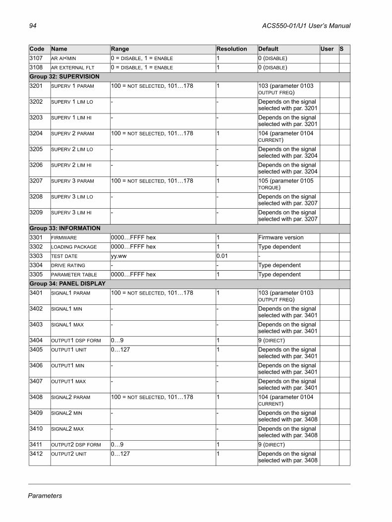
94 ACS550-01/U1 User’s Manual
3107 AR AI<MIN 0 = DISABLE, 1 = ENABLE 1 0 (DISABLE)3108 AR EXTERNAL FLT 0 = DISABLE, 1 = ENABLE 1 0 (DISABLE)Group 32: SUPERVISION3201 SUPERV 1 PARAM 100 = NOT SELECTED, 101…178 1 103 (parameter 0103
OUTPUT FREQ)3202 SUPERV 1 LIM LO - - Depends on the signal
selected with par. 32013203 SUPERV 1 LIM HI - - Depends on the signal
selected with par. 32013204 SUPERV 2 PARAM 100 = NOT SELECTED, 101…178 1 104 (parameter 0104
CURRENT)3205 SUPERV 2 LIM LO - - Depends on the signal
selected with par. 32043206 SUPERV 2 LIM HI - - Depends on the signal
selected with par. 32043207 SUPERV 3 PARAM 100 = NOT SELECTED, 101…178 1 105 (parameter 0105
TORQUE)3208 SUPERV 3 LIM LO - - Depends on the signal
selected with par. 32073209 SUPERV 3 LIM HI - - Depends on the signal
selected with par. 3207Group 33: INFORMATION3301 FIRMWARE 0000…FFFF hex 1 Firmware version3302 LOADING PACKAGE 0000…FFFF hex 1 Type dependent3303 TEST DATE yy.ww 0.01 -3304 DRIVE RATING - - Type dependent3305 PARAMETER TABLE 0000…FFFF hex 1 Type dependentGroup 34: PANEL DISPLAY3401 SIGNAL1 PARAM 100 = NOT SELECTED, 101…178 1 103 (parameter 0103
OUTPUT FREQ)3402 SIGNAL1 MIN - - Depends on the signal
selected with par. 34013403 SIGNAL1 MAX - - Depends on the signal
selected with par. 34013404 OUTPUT1 DSP FORM 0…9 1 9 (DIRECT)3405 OUTPUT1 UNIT 0…127 1 Depends on the signal
selected with par. 34013406 OUTPUT1 MIN - - Depends on the signal
selected with par. 34013407 OUTPUT1 MAX - - Depends on the signal
selected with par. 34013408 SIGNAL2 PARAM 100 = NOT SELECTED, 101…178 1 104 (parameter 0104
CURRENT)3409 SIGNAL2 MIN - - Depends on the signal
selected with par. 34083410 SIGNAL2 MAX - - Depends on the signal
selected with par. 34083411 OUTPUT2 DSP FORM 0…9 1 9 (DIRECT)3412 OUTPUT2 UNIT 0…127 1 Depends on the signal
selected with par. 3408
Code Name Range Resolution Default User S
Parameters
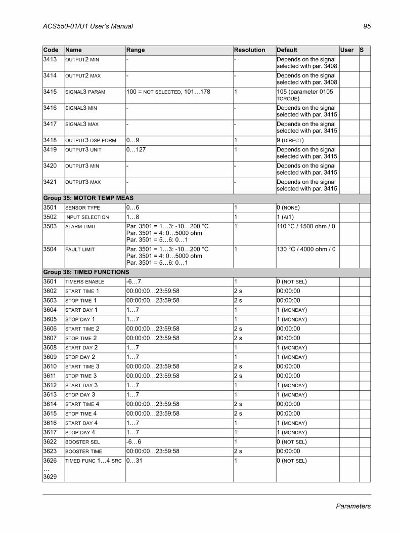
ACS550-01/U1 User’s Manual 95
3413 OUTPUT2 MIN - - Depends on the signal selected with par. 3408
3414 OUTPUT2 MAX - - Depends on the signal selected with par. 3408
3415 SIGNAL3 PARAM 100 = NOT SELECTED, 101…178 1 105 (parameter 0105 TORQUE)
3416 SIGNAL3 MIN - - Depends on the signal selected with par. 3415
3417 SIGNAL3 MAX - - Depends on the signal selected with par. 3415
3418 OUTPUT3 DSP FORM 0…9 1 9 (DIRECT)3419 OUTPUT3 UNIT 0…127 1 Depends on the signal
selected with par. 34153420 OUTPUT3 MIN - - Depends on the signal
selected with par. 34153421 OUTPUT3 MAX - - Depends on the signal
selected with par. 3415Group 35: MOTOR TEMP MEAS3501 SENSOR TYPE 0…6 1 0 (NONE)3502 INPUT SELECTION 1…8 1 1 (AI1)3503 ALARM LIMIT Par. 3501 = 1…3: -10…200 °C
Par. 3501 = 4: 0…5000 ohmPar. 3501 = 5…6: 0…1
1 110 °C / 1500 ohm / 0
3504 FAULT LIMIT Par. 3501 = 1…3: -10…200 °CPar. 3501 = 4: 0…5000 ohmPar. 3501 = 5…6: 0…1
1 130 °C / 4000 ohm / 0
Group 36: TIMED FUNCTIONS3601 TIMERS ENABLE -6…7 1 0 (NOT SEL)3602 START TIME 1 00:00:00…23:59:58 2 s 00:00:003603 STOP TIME 1 00:00:00…23:59:58 2 s 00:00:003604 START DAY 1 1…7 1 1 (MONDAY)3605 STOP DAY 1 1…7 1 1 (MONDAY)3606 START TIME 2 00:00:00…23:59:58 2 s 00:00:003607 STOP TIME 2 00:00:00…23:59:58 2 s 00:00:003608 START DAY 2 1…7 1 1 (MONDAY)3609 STOP DAY 2 1…7 1 1 (MONDAY)3610 START TIME 3 00:00:00…23:59:58 2 s 00:00:003611 STOP TIME 3 00:00:00…23:59:58 2 s 00:00:003612 START DAY 3 1…7 1 1 (MONDAY)3613 STOP DAY 3 1…7 1 1 (MONDAY)3614 START TIME 4 00:00:00…23:59:58 2 s 00:00:003615 STOP TIME 4 00:00:00…23:59:58 2 s 00:00:003616 START DAY 4 1…7 1 1 (MONDAY)3617 STOP DAY 4 1…7 1 1 (MONDAY)3622 BOOSTER SEL -6…6 1 0 (NOT SEL)3623 BOOSTER TIME 00:00:00…23:59:58 2 s 00:00:003626…3629
TIMED FUNC 1…4 SRC 0…31 1 0 (NOT SEL)
Code Name Range Resolution Default User S
Parameters
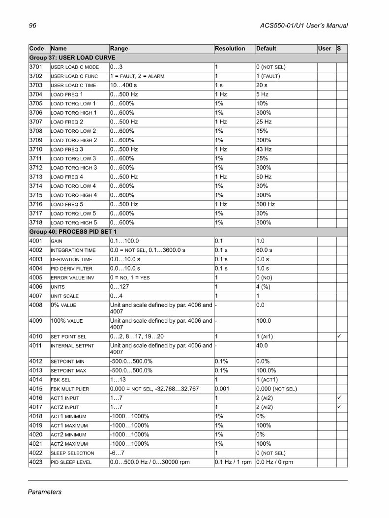
96 ACS550-01/U1 User’s Manual
Group 37: USER LOAD CURVE3701 USER LOAD C MODE 0…3 1 0 (NOT SEL)3702 USER LOAD C FUNC 1 = FAULT, 2 = ALARM 1 1 (FAULT)3703 USER LOAD C TIME 10…400 s 1 s 20 s3704 LOAD FREQ 1 0…500 Hz 1 Hz 5 Hz3705 LOAD TORQ LOW 1 0…600% 1% 10%3706 LOAD TORQ HIGH 1 0…600% 1% 300%3707 LOAD FREQ 2 0…500 Hz 1 Hz 25 Hz3708 LOAD TORQ LOW 2 0…600% 1% 15%3709 LOAD TORQ HIGH 2 0…600% 1% 300%3710 LOAD FREQ 3 0…500 Hz 1 Hz 43 Hz3711 LOAD TORQ LOW 3 0…600% 1% 25%3712 LOAD TORQ HIGH 3 0…600% 1% 300%3713 LOAD FREQ 4 0…500 Hz 1 Hz 50 Hz3714 LOAD TORQ LOW 4 0…600% 1% 30%3715 LOAD TORQ HIGH 4 0…600% 1% 300%3716 LOAD FREQ 5 0…500 Hz 1 Hz 500 Hz3717 LOAD TORQ LOW 5 0…600% 1% 30%3718 LOAD TORQ HIGH 5 0…600% 1% 300%Group 40: PROCESS PID SET 14001 GAIN 0.1…100.0 0.1 1.04002 INTEGRATION TIME 0.0 = NOT SEL, 0.1…3600.0 s 0.1 s 60.0 s4003 DERIVATION TIME 0.0…10.0 s 0.1 s 0.0 s4004 PID DERIV FILTER 0.0…10.0 s 0.1 s 1.0 s4005 ERROR VALUE INV 0 = NO, 1 = YES 1 0 (NO) 4006 UNITS 0…127 1 4 (%)4007 UNIT SCALE 0…4 1 14008 0% VALUE Unit and scale defined by par. 4006 and
4007- 0.0
4009 100% VALUE Unit and scale defined by par. 4006 and 4007
- 100.0
4010 SET POINT SEL 0…2, 8…17, 19…20 1 1 (AI1)4011 INTERNAL SETPNT Unit and scale defined by par. 4006 and
4007- 40.0
4012 SETPOINT MIN -500.0…500.0% 0.1% 0.0%4013 SETPOINT MAX -500.0…500.0% 0.1% 100.0%4014 FBK SEL 1…13 1 1 (ACT1)4015 FBK MULTIPLIER 0.000 = NOT SEL, -32.768…32.767 0.001 0.000 (NOT SEL)4016 ACT1 INPUT 1…7 1 2 (AI2)4017 ACT2 INPUT 1…7 1 2 (AI2)4018 ACT1 MINIMUM -1000…1000% 1% 0%4019 ACT1 MAXIMUM -1000…1000% 1% 100%4020 ACT2 MINIMUM -1000…1000% 1% 0%4021 ACT2 MAXIMUM -1000…1000% 1% 100%4022 SLEEP SELECTION -6…7 1 0 (NOT SEL)4023 PID SLEEP LEVEL 0.0…500.0 Hz / 0…30000 rpm 0.1 Hz / 1 rpm 0.0 Hz / 0 rpm
Code Name Range Resolution Default User S
Parameters
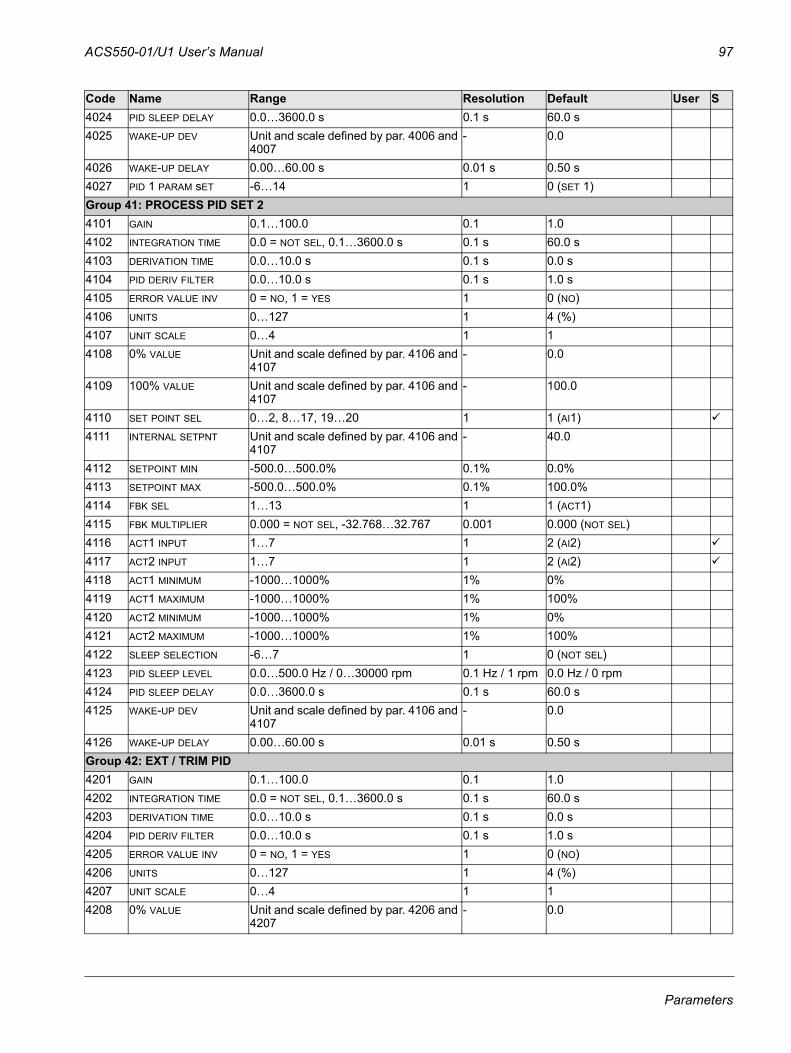
ACS550-01/U1 User’s Manual 97
4024 PID SLEEP DELAY 0.0…3600.0 s 0.1 s 60.0 s4025 WAKE-UP DEV Unit and scale defined by par. 4006 and
4007- 0.0
4026 WAKE-UP DELAY 0.00…60.00 s 0.01 s 0.50 s4027 PID 1 PARAM sET -6…14 1 0 (SET 1)Group 41: PROCESS PID SET 24101 GAIN 0.1…100.0 0.1 1.04102 INTEGRATION TIME 0.0 = NOT SEL, 0.1…3600.0 s 0.1 s 60.0 s4103 DERIVATION TIME 0.0…10.0 s 0.1 s 0.0 s4104 PID DERIV FILTER 0.0…10.0 s 0.1 s 1.0 s4105 ERROR VALUE INV 0 = NO, 1 = YES 1 0 (NO)4106 UNITS 0…127 1 4 (%)4107 UNIT SCALE 0…4 1 14108 0% VALUE Unit and scale defined by par. 4106 and
4107- 0.0
4109 100% VALUE Unit and scale defined by par. 4106 and 4107
- 100.0
4110 SET POINT SEL 0…2, 8…17, 19…20 1 1 (AI1)4111 INTERNAL SETPNT Unit and scale defined by par. 4106 and
4107- 40.0
4112 SETPOINT MIN -500.0…500.0% 0.1% 0.0%4113 SETPOINT MAX -500.0…500.0% 0.1% 100.0%4114 FBK SEL 1…13 1 1 (ACT1)4115 FBK MULTIPLIER 0.000 = NOT SEL, -32.768…32.767 0.001 0.000 (NOT SEL)4116 ACT1 INPUT 1…7 1 2 (AI2)4117 ACT2 INPUT 1…7 1 2 (AI2)4118 ACT1 MINIMUM -1000…1000% 1% 0%4119 ACT1 MAXIMUM -1000…1000% 1% 100%4120 ACT2 MINIMUM -1000…1000% 1% 0%4121 ACT2 MAXIMUM -1000…1000% 1% 100%4122 SLEEP SELECTION -6…7 1 0 (NOT SEL)4123 PID SLEEP LEVEL 0.0…500.0 Hz / 0…30000 rpm 0.1 Hz / 1 rpm 0.0 Hz / 0 rpm4124 PID SLEEP DELAY 0.0…3600.0 s 0.1 s 60.0 s4125 WAKE-UP DEV Unit and scale defined by par. 4106 and
4107- 0.0
4126 WAKE-UP DELAY 0.00…60.00 s 0.01 s 0.50 sGroup 42: EXT / TRIM PID4201 GAIN 0.1…100.0 0.1 1.04202 INTEGRATION TIME 0.0 = NOT SEL, 0.1…3600.0 s 0.1 s 60.0 s4203 DERIVATION TIME 0.0…10.0 s 0.1 s 0.0 s4204 PID DERIV FILTER 0.0…10.0 s 0.1 s 1.0 s4205 ERROR VALUE INV 0 = NO, 1 = YES 1 0 (NO) 4206 UNITS 0…127 1 4 (%)4207 UNIT SCALE 0…4 1 14208 0% VALUE Unit and scale defined by par. 4206 and
4207- 0.0
Code Name Range Resolution Default User S
Parameters
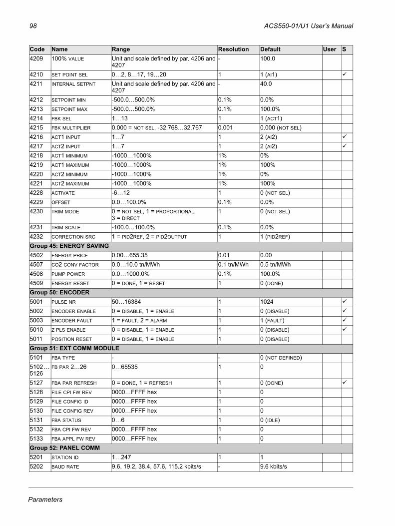
98 ACS550-01/U1 User’s Manual
4209 100% VALUE Unit and scale defined by par. 4206 and 4207
- 100.0
4210 SET POINT SEL 0…2, 8…17, 19…20 1 1 (AI1)4211 INTERNAL SETPNT Unit and scale defined by par. 4206 and
4207- 40.0
4212 SETPOINT MIN -500.0…500.0% 0.1% 0.0%4213 SETPOINT MAX -500.0…500.0% 0.1% 100.0%4214 FBK SEL 1…13 1 1 (ACT1)4215 FBK MULTIPLIER 0.000 = NOT SEL, -32.768…32.767 0.001 0.000 (NOT SEL)4216 ACT1 INPUT 1…7 1 2 (AI2)4217 ACT2 INPUT 1…7 1 2 (AI2)4218 ACT1 MINIMUM -1000…1000% 1% 0%4219 ACT1 MAXIMUM -1000…1000% 1% 100%4220 ACT2 MINIMUM -1000…1000% 1% 0%4221 ACT2 MAXIMUM -1000…1000% 1% 100%4228 ACTIVATE -6…12 1 0 (NOT SEL)4229 OFFSET 0.0…100.0% 0.1% 0.0%4230 TRIM MODE 0 = NOT SEL, 1 = PROPORTIONAL,
3 = DIRECT1 0 (NOT SEL)
4231 TRIM SCALE -100.0…100.0% 0.1% 0.0%4232 CORRECTION SRC 1 = PID2REF, 2 = PID2OUTPUT 1 1 (PID2REF)Group 45: ENERGY SAVING4502 ENERGY PRICE 0.00…655.35 0.01 0.004507 CO2 CONV FACTOR 0.0…10.0 tn/MWh 0.1 tn/MWh 0.5 tn/MWh4508 PUMP POWER 0.0…1000.0% 0.1% 100.0%4509 ENERGY RESET 0 = DONE, 1 = RESET 1 0 (DONE)Group 50: ENCODER5001 PULSE NR 50…16384 1 10245002 ENCODER ENABLE 0 = DISABLE, 1 = ENABLE 1 0 (DISABLE)5003 ENCODER FAULT 1 = FAULT, 2 = ALARM 1 1 (FAULT)5010 Z PLS ENABLE 0 = DISABLE, 1 = ENABLE 1 0 (DISABLE)5011 POSITION RESET 0 = DISABLE, 1 = ENABLE 1 0 (DISABLE)Group 51: EXT COMM MODULE5101 FBA TYPE - - 0 (NOT DEFINED)5102 … 5126
FB PAR 2…26 0…65535 1 0
5127 FBA PAR REFRESH 0 = DONE, 1 = REFRESH 1 0 (DONE)5128 FILE CPI FW REV 0000…FFFF hex 1 05129 FILE CONFIG ID 0000…FFFF hex 1 05130 FILE CONFIG REV 0000…FFFF hex 1 05131 FBA STATUS 0…6 1 0 (IDLE)5132 FBA CPI FW REV 0000…FFFF hex 1 05133 FBA APPL FW REV 0000…FFFF hex 1 0Group 52: PANEL COMM5201 STATION ID 1…247 1 15202 BAUD RATE 9.6, 19.2, 38.4, 57.6, 115.2 kbits/s - 9.6 kbits/s
Code Name Range Resolution Default User S
Parameters
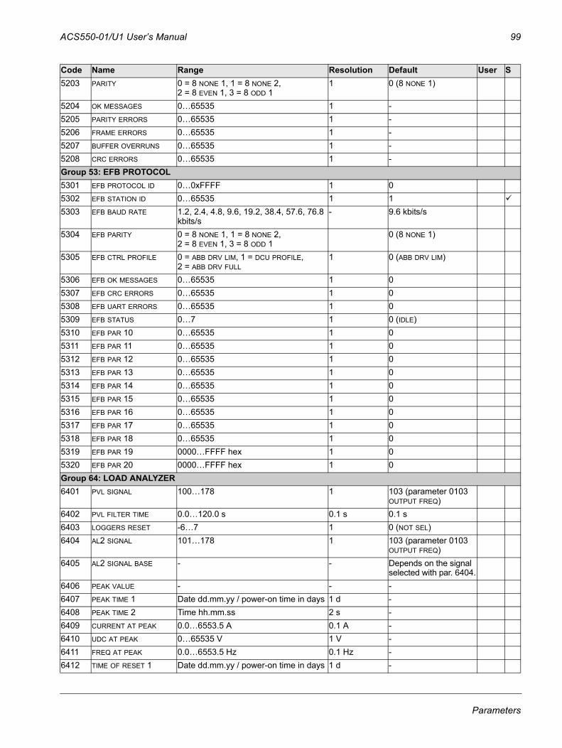
ACS550-01/U1 User’s Manual 99
5203 PARITY 0 = 8 NONE 1, 1 = 8 NONE 2, 2 = 8 EVEN 1, 3 = 8 ODD 1
1 0 (8 NONE 1)
5204 OK MESSAGES 0…65535 1 -5205 PARITY ERRORS 0…65535 1 -5206 FRAME ERRORS 0…65535 1 -5207 BUFFER OVERRUNS 0…65535 1 -5208 CRC ERRORS 0…65535 1 -Group 53: EFB PROTOCOL5301 EFB PROTOCOL ID 0…0xFFFF 1 05302 EFB STATION ID 0…65535 1 15303 EFB BAUD RATE 1.2, 2.4, 4.8, 9.6, 19.2, 38.4, 57.6, 76.8
kbits/s- 9.6 kbits/s
5304 EFB PARITY 0 = 8 NONE 1, 1 = 8 NONE 2, 2 = 8 EVEN 1, 3 = 8 ODD 1
0 (8 NONE 1)
5305 EFB CTRL PROFILE 0 = ABB DRV LIM, 1 = DCU PROFILE, 2 = ABB DRV FULL
1 0 (ABB DRV LIM)
5306 EFB OK MESSAGES 0…65535 1 05307 EFB CRC ERRORS 0…65535 1 05308 EFB UART ERRORS 0…65535 1 05309 EFB STATUS 0…7 1 0 (IDLE)5310 EFB PAR 10 0…65535 1 0 5311 EFB PAR 11 0…65535 1 0 5312 EFB PAR 12 0…65535 1 0 5313 EFB PAR 13 0…65535 1 0 5314 EFB PAR 14 0…65535 1 0 5315 EFB PAR 15 0…65535 1 0 5316 EFB PAR 16 0…65535 1 0 5317 EFB PAR 17 0…65535 1 0 5318 EFB PAR 18 0…65535 1 05319 EFB PAR 19 0000…FFFF hex 1 05320 EFB PAR 20 0000…FFFF hex 1 0Group 64: LOAD ANALYZER6401 PVL SIGNAL 100…178 1 103 (parameter 0103
OUTPUT FREQ)6402 PVL FILTER TIME 0.0…120.0 s 0.1 s 0.1 s6403 LOGGERS RESET -6…7 1 0 (NOT SEL)6404 AL2 SIGNAL 101…178 1 103 (parameter 0103
OUTPUT FREQ)6405 AL2 SIGNAL BASE - - Depends on the signal
selected with par. 6404.6406 PEAK VALUE - - -6407 PEAK TIME 1 Date dd.mm.yy / power-on time in days 1 d -6408 PEAK TIME 2 Time hh.mm.ss 2 s -6409 CURRENT AT PEAK 0.0…6553.5 A 0.1 A -6410 UDC AT PEAK 0…65535 V 1 V -6411 FREQ AT PEAK 0.0…6553.5 Hz 0.1 Hz -6412 TIME OF RESET 1 Date dd.mm.yy / power-on time in days 1 d -
Code Name Range Resolution Default User S
Parameters
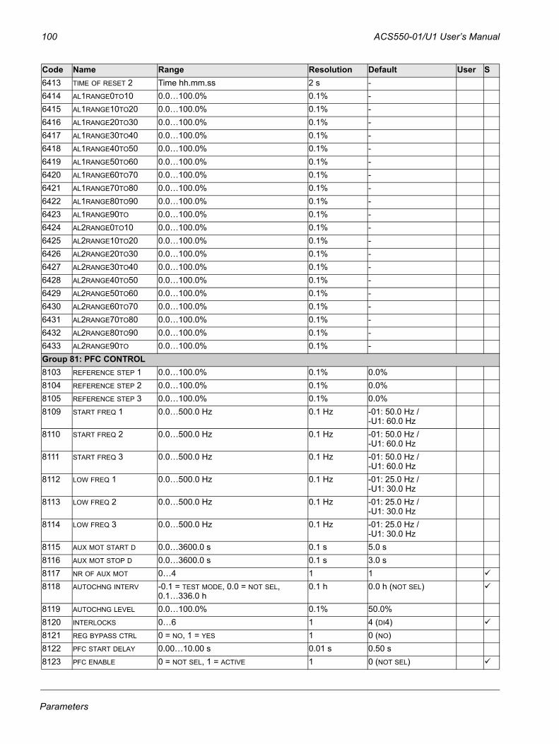
100 ACS550-01/U1 User’s Manual
6413 TIME OF RESET 2 Time hh.mm.ss 2 s -6414 AL1RANGE0TO10 0.0…100.0% 0.1% -6415 AL1RANGE10TO20 0.0…100.0% 0.1% -6416 AL1RANGE20TO30 0.0…100.0% 0.1% -6417 AL1RANGE30TO40 0.0…100.0% 0.1% -6418 AL1RANGE40TO50 0.0…100.0% 0.1% -6419 AL1RANGE50TO60 0.0…100.0% 0.1% -6420 AL1RANGE60TO70 0.0…100.0% 0.1% -6421 AL1RANGE70TO80 0.0…100.0% 0.1% -6422 AL1RANGE80TO90 0.0…100.0% 0.1% -6423 AL1RANGE90TO 0.0…100.0% 0.1% -6424 AL2RANGE0TO10 0.0…100.0% 0.1% -6425 AL2RANGE10TO20 0.0…100.0% 0.1% -6426 AL2RANGE20TO30 0.0…100.0% 0.1% -6427 AL2RANGE30TO40 0.0…100.0% 0.1% -6428 AL2RANGE40TO50 0.0…100.0% 0.1% -6429 AL2RANGE50TO60 0.0…100.0% 0.1% -6430 AL2RANGE60TO70 0.0…100.0% 0.1% -6431 AL2RANGE70TO80 0.0…100.0% 0.1% -6432 AL2RANGE80TO90 0.0…100.0% 0.1% -6433 AL2RANGE90TO 0.0…100.0% 0.1% -Group 81: PFC CONTROL 8103 REFERENCE STEP 1 0.0…100.0% 0.1% 0.0%8104 REFERENCE STEP 2 0.0…100.0% 0.1% 0.0%8105 REFERENCE STEP 3 0.0…100.0% 0.1% 0.0%8109 START FREQ 1 0.0…500.0 Hz 0.1 Hz -01: 50.0 Hz /
-U1: 60.0 Hz8110 START FREQ 2 0.0…500.0 Hz 0.1 Hz -01: 50.0 Hz /
-U1: 60.0 Hz8111 START FREQ 3 0.0…500.0 Hz 0.1 Hz -01: 50.0 Hz /
-U1: 60.0 Hz8112 LOW FREQ 1 0.0…500.0 Hz 0.1 Hz -01: 25.0 Hz /
-U1: 30.0 Hz8113 LOW FREQ 2 0.0…500.0 Hz 0.1 Hz -01: 25.0 Hz /
-U1: 30.0 Hz8114 LOW FREQ 3 0.0…500.0 Hz 0.1 Hz -01: 25.0 Hz /
-U1: 30.0 Hz8115 AUX MOT START D 0.0…3600.0 s 0.1 s 5.0 s8116 AUX MOT STOP D 0.0…3600.0 s 0.1 s 3.0 s8117 NR OF AUX MOT 0…4 1 18118 AUTOCHNG INTERV -0.1 = TEST MODE, 0.0 = NOT SEL,
0.1…336.0 h0.1 h 0.0 h (NOT SEL)
8119 AUTOCHNG LEVEL 0.0…100.0% 0.1% 50.0%8120 INTERLOCKS 0…6 1 4 (DI4)8121 REG BYPASS CTRL 0 = NO, 1 = YES 1 0 (NO)8122 PFC START DELAY 0.00…10.00 s 0.01 s 0.50 s8123 PFC ENABLE 0 = NOT SEL, 1 = ACTIVE 1 0 (NOT SEL)
Code Name Range Resolution Default User S
Parameters

ACS550-01/U1 User’s Manual 101
8124 ACC IN AUX STOP 0.0 = NOT SEL, 0.1…1800.0 s 0.1 s 0.0 s (NOT SEL)8125 DEC IN AUX START 0.0 = NOT SEL, 0.1…1800.0 s 0.1 s 0.0 s (NOT SEL)8126 TMED AUTOCHNG 0…4 1 0 (NOT SEL)8127 MOTORS 1…7 1 28128 AUX START ORDER 1 = EVEN RUNTIME, 2 = RELAY ORDER 1 1 (EVEN RUNTIME)Group 98: OPTIONS9802 COMM PROT SEL 0 = NOT SEL, 1 = STD MODBUS,
4 = EXT FBA1 0 (NOT SEL)
Code Name Range Resolution Default User S
Parameters
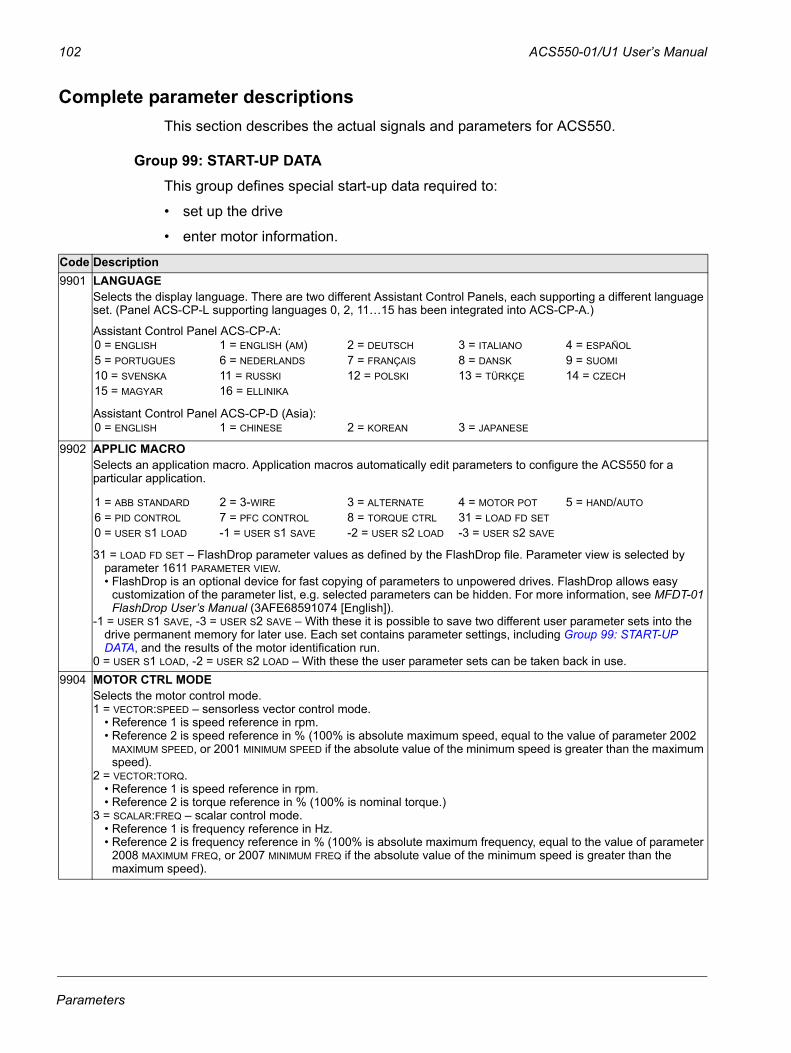
102 ACS550-01/U1 User’s Manual
Complete parameter descriptionsThis section describes the actual signals and parameters for ACS550.
Group 99: START-UP DATAThis group defines special start-up data required to:
• set up the drive
• enter motor information.
Code Description9901 LANGUAGE
Selects the display language. There are two different Assistant Control Panels, each supporting a different language set. (Panel ACS-CP-L supporting languages 0, 2, 11…15 has been integrated into ACS-CP-A.)
9902 APPLIC MACRO Selects an application macro. Application macros automatically edit parameters to configure the ACS550 for a particular application.
31 = LOAD FD SET – FlashDrop parameter values as defined by the FlashDrop file. Parameter view is selected by parameter 1611 PARAMETER VIEW.• FlashDrop is an optional device for fast copying of parameters to unpowered drives. FlashDrop allows easy
customization of the parameter list, e.g. selected parameters can be hidden. For more information, see MFDT-01 FlashDrop User’s Manual (3AFE68591074 [English]).
-1 = USER S1 SAVE, -3 = USER S2 SAVE – With these it is possible to save two different user parameter sets into the drive permanent memory for later use. Each set contains parameter settings, including Group 99: START-UP DATA, and the results of the motor identification run.
0 = USER S1 LOAD, -2 = USER S2 LOAD – With these the user parameter sets can be taken back in use.9904 MOTOR CTRL MODE
Selects the motor control mode.1 = VECTOR:SPEED – sensorless vector control mode.
• Reference 1 is speed reference in rpm.• Reference 2 is speed reference in % (100% is absolute maximum speed, equal to the value of parameter 2002
MAXIMUM SPEED, or 2001 MINIMUM SPEED if the absolute value of the minimum speed is greater than the maximum speed).
2 = VECTOR:TORQ.• Reference 1 is speed reference in rpm. • Reference 2 is torque reference in % (100% is nominal torque.)
3 = SCALAR:FREQ – scalar control mode.• Reference 1 is frequency reference in Hz. • Reference 2 is frequency reference in % (100% is absolute maximum frequency, equal to the value of parameter
2008 MAXIMUM FREQ, or 2007 MINIMUM FREQ if the absolute value of the minimum speed is greater than the maximum speed).
Assistant Control Panel ACS-CP-A:
Assistant Control Panel ACS-CP-D (Asia):
0 = ENGLISH 1 = ENGLISH (AM) 2 = DEUTSCH 3 = ITALIANO 4 = ESPAÑOL5 = PORTUGUES 6 = NEDERLANDS 7 = FRANÇAIS 8 = DANSK 9 = SUOMI10 = SVENSKA 11 = RUSSKI 12 = POLSKI 13 = TÜRKÇE 14 = CZECH15 = MAGYAR 16 = ELLINIKA
0 = ENGLISH 1 = CHINESE 2 = KOREAN 3 = JAPANESE
1 = ABB STANDARD 2 = 3-WIRE 3 = ALTERNATE 4 = MOTOR POT 5 = HAND/AUTO6 = PID CONTROL 7 = PFC CONTROL 8 = TORQUE CTRL 31 = LOAD FD SET0 = USER S1 LOAD -1 = USER S1 SAVE -2 = USER S2 LOAD -3 = USER S2 SAVE
Parameters
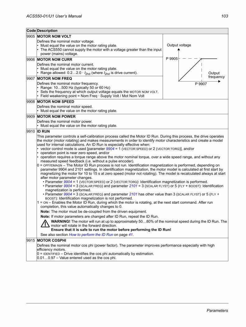
ACS550-01/U1 User’s Manual 103
9905 MOTOR NOM VOLTDefines the nominal motor voltage. • Must equal the value on the motor rating plate. • The ACS550 cannot supply the motor with a voltage greater than the input
power (mains) voltage.9906 MOTOR NOM CURR
Defines the nominal motor current. • Must equal the value on the motor rating plate. • Range allowed: 0.2…2.0 · I2hd (where I2hd is drive current).
9907 MOTOR NOM FREQDefines the nominal motor frequency.• Range: 10…500 Hz (typically 50 or 60 Hz)• Sets the frequency at which output voltage equals the MOTOR NOM VOLT. • Field weakening point = Nom Freq · Supply Volt / Mot Nom Volt
9908 MOTOR NOM SPEEDDefines the nominal motor speed. • Must equal the value on the motor rating plate.
9909 MOTOR NOM POWERDefines the nominal motor power. • Must equal the value on the motor rating plate.
9910 ID RUNThis parameter controls a self-calibration process called the Motor ID Run. During this process, the drive operates the motor (motor rotating) and makes measurements in order to identify motor characteristics and create a model used for internal calculations. An ID Run is especially effective when:• vector control mode is used [parameter 9904 = 1 (VECTOR:SPEED) or 2 (VECTOR:TORQ)], and/or• operation point is near zero speed, and/or• operation requires a torque range above the motor nominal torque, over a wide speed range, and without any
measured speed feedback (i.e. without a pulse encoder).0 = OFF/IDMAGN – The Motor ID Run process is not run. Identification magnetization is performed, depending on
parameter 9904 and 2101 settings. In identification magnetization, the motor model is calculated at first start by magnetizing the motor for 10 to 15 s at zero speed (motor not rotating). The model is recalculated always at start after motor parameter changes.
• Parameter 9904 = 1 (VECTOR:SPEED) or 2 (VECTOR:TORQ): Identification magnetization is performed.• Parameter 9904 = 3 (SCALAR:FREQ) and parameter 2101 = 3 (SCALAR FLYST) or 5 (FLY + BOOST): Identification
magnetization is performed.• Parameter 9904 = 3 (SCALAR:FREQ) and parameter 2101 has other value than 3 (SCALAR FLYST) or 5 (FLY +
BOOST): Identification magnetization is not performed.1 = ON – Enables the Motor ID Run, during which the motor is rotating, at the next start command. After run
completion, this value automatically changes to 0. Note: The motor must be de-coupled from the driven equipment.Note: If motor parameters are changed after ID Run, repeat the ID Run.
WARNING! The motor will run at up to approximately 50…80% of the nominal speed during the ID Run. The motor will rotate in the forward direction.Ensure that it is safe to run the motor before performing the ID Run!
See also section How to perform the ID Run on page 41.9915 MOTOR COSPHI
Defines the nominal motor cos phi (power factor). The parameter improves performance especially with high efficiency motors.0 = IDENTIFIED – Drive identifies the cos phi automatically by estimation.0.01…0.97 – Value entered used as the cos phi.
Code Description
P 9907
P 9905
Outputfrequency
Output voltage
Parameters
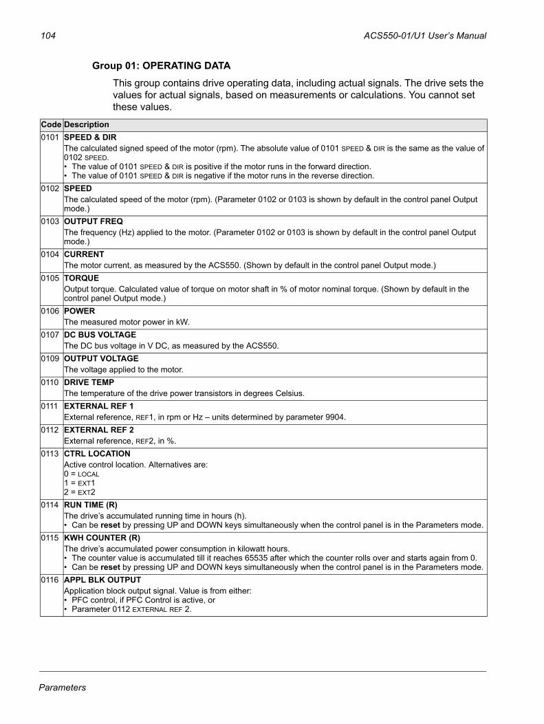
104 ACS550-01/U1 User’s Manual
Group 01: OPERATING DATAThis group contains drive operating data, including actual signals. The drive sets the values for actual signals, based on measurements or calculations. You cannot set these values.
Code Description0101 SPEED & DIR
The calculated signed speed of the motor (rpm). The absolute value of 0101 SPEED & DIR is the same as the value of 0102 SPEED.• The value of 0101 SPEED & DIR is positive if the motor runs in the forward direction.• The value of 0101 SPEED & DIR is negative if the motor runs in the reverse direction.
0102 SPEEDThe calculated speed of the motor (rpm). (Parameter 0102 or 0103 is shown by default in the control panel Output mode.)
0103 OUTPUT FREQThe frequency (Hz) applied to the motor. (Parameter 0102 or 0103 is shown by default in the control panel Output mode.)
0104 CURRENTThe motor current, as measured by the ACS550. (Shown by default in the control panel Output mode.)
0105 TORQUEOutput torque. Calculated value of torque on motor shaft in % of motor nominal torque. (Shown by default in the control panel Output mode.)
0106 POWERThe measured motor power in kW.
0107 DC BUS VOLTAGEThe DC bus voltage in V DC, as measured by the ACS550.
0109 OUTPUT VOLTAGEThe voltage applied to the motor.
0110 DRIVE TEMPThe temperature of the drive power transistors in degrees Celsius.
0111 EXTERNAL REF 1External reference, REF1, in rpm or Hz – units determined by parameter 9904.
0112 EXTERNAL REF 2External reference, REF2, in %.
0113 CTRL LOCATIONActive control location. Alternatives are: 0 = LOCAL1 = EXT12 = EXT2
0114 RUN TIME (R)The drive’s accumulated running time in hours (h). • Can be reset by pressing UP and DOWN keys simultaneously when the control panel is in the Parameters mode.
0115 KWH COUNTER (R)The drive’s accumulated power consumption in kilowatt hours. • The counter value is accumulated till it reaches 65535 after which the counter rolls over and starts again from 0.• Can be reset by pressing UP and DOWN keys simultaneously when the control panel is in the Parameters mode.
0116 APPL BLK OUTPUTApplication block output signal. Value is from either:• PFC control, if PFC Control is active, or• Parameter 0112 EXTERNAL REF 2.
Parameters
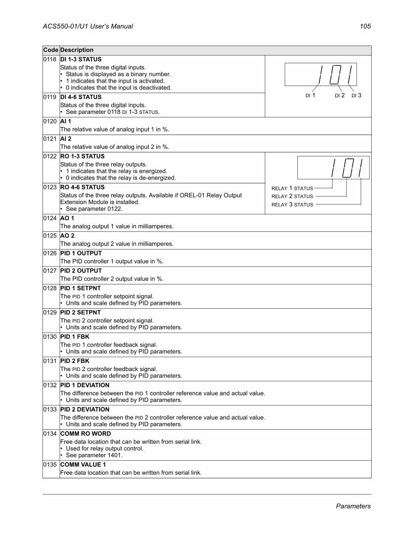
ACS550-01/U1 User’s Manual 105
0118 DI 1-3 STATUSStatus of the three digital inputs. • Status is displayed as a binary number. • 1 indicates that the input is activated.• 0 indicates that the input is deactivated.
0119 DI 4-6 STATUSStatus of the three digital inputs. • See parameter 0118 DI 1-3 STATUS.
0120 AI 1The relative value of analog input 1 in %.
0121 AI 2The relative value of analog input 2 in %.
0122 RO 1-3 STATUSStatus of the three relay outputs. • 1 indicates that the relay is energized.• 0 indicates that the relay is de-energized.
0123 RO 4-6 STATUSStatus of the three relay outputs. Available if OREL-01 Relay Output Extension Module is installed.• See parameter 0122.
0124 AO 1The analog output 1 value in milliamperes.
0125 AO 2The analog output 2 value in milliamperes.
0126 PID 1 OUTPUTThe PID controller 1 output value in %.
0127 PID 2 OUTPUTThe PID controller 2 output value in %.
0128 PID 1 SETPNTThe PID 1 controller setpoint signal. • Units and scale defined by PID parameters.
0129 PID 2 SETPNTThe PID 2 controller setpoint signal. • Units and scale defined by PID parameters.
0130 PID 1 FBKThe PID 1 controller feedback signal. • Units and scale defined by PID parameters.
0131 PID 2 FBKThe PID 2 controller feedback signal. • Units and scale defined by PID parameters.
0132 PID 1 DEVIATIONThe difference between the PID 1 controller reference value and actual value.• Units and scale defined by PID parameters.
0133 PID 2 DEVIATIONThe difference between the PID 2 controller reference value and actual value.• Units and scale defined by PID parameters.
0134 COMM RO WORDFree data location that can be written from serial link. • Used for relay output control. • See parameter 1401.
0135 COMM VALUE 1Free data location that can be written from serial link.
Code Description
DI 1 DI 2 DI 3
RELAY 1 STATUSRELAY 2 STATUS
RELAY 3 STATUS
Parameters
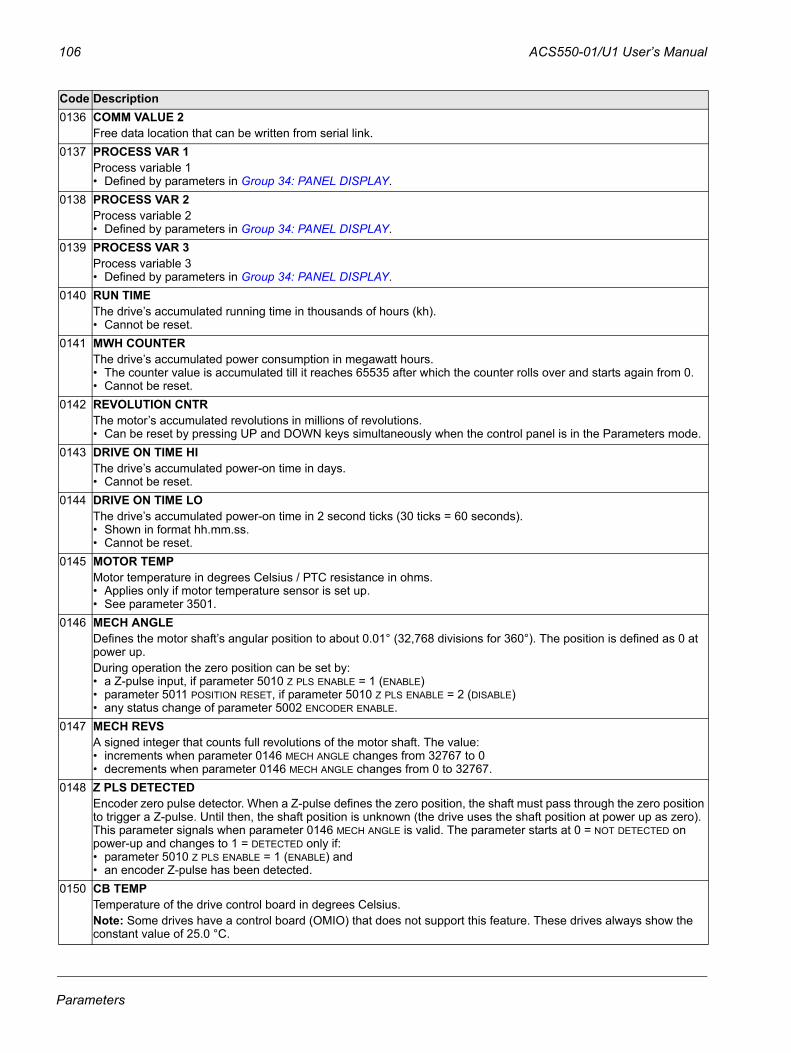
106 ACS550-01/U1 User’s Manual
0136 COMM VALUE 2Free data location that can be written from serial link.
0137 PROCESS VAR 1Process variable 1 • Defined by parameters in Group 34: PANEL DISPLAY.
0138 PROCESS VAR 2Process variable 2 • Defined by parameters in Group 34: PANEL DISPLAY.
0139 PROCESS VAR 3Process variable 3 • Defined by parameters in Group 34: PANEL DISPLAY.
0140 RUN TIMEThe drive’s accumulated running time in thousands of hours (kh). • Cannot be reset.
0141 MWH COUNTERThe drive’s accumulated power consumption in megawatt hours. • The counter value is accumulated till it reaches 65535 after which the counter rolls over and starts again from 0.• Cannot be reset.
0142 REVOLUTION CNTRThe motor’s accumulated revolutions in millions of revolutions. • Can be reset by pressing UP and DOWN keys simultaneously when the control panel is in the Parameters mode.
0143 DRIVE ON TIME HIThe drive’s accumulated power-on time in days. • Cannot be reset.
0144 DRIVE ON TIME LOThe drive’s accumulated power-on time in 2 second ticks (30 ticks = 60 seconds). • Shown in format hh.mm.ss. • Cannot be reset.
0145 MOTOR TEMPMotor temperature in degrees Celsius / PTC resistance in ohms. • Applies only if motor temperature sensor is set up. • See parameter 3501.
0146 MECH ANGLEDefines the motor shaft’s angular position to about 0.01° (32,768 divisions for 360°). The position is defined as 0 at power up. During operation the zero position can be set by:• a Z-pulse input, if parameter 5010 Z PLS ENABLE = 1 (ENABLE)• parameter 5011 POSITION RESET, if parameter 5010 Z PLS ENABLE = 2 (DISABLE)• any status change of parameter 5002 ENCODER ENABLE.
0147 MECH REVSA signed integer that counts full revolutions of the motor shaft. The value:• increments when parameter 0146 MECH ANGLE changes from 32767 to 0• decrements when parameter 0146 MECH ANGLE changes from 0 to 32767.
0148 Z PLS DETECTEDEncoder zero pulse detector. When a Z-pulse defines the zero position, the shaft must pass through the zero position to trigger a Z-pulse. Until then, the shaft position is unknown (the drive uses the shaft position at power up as zero). This parameter signals when parameter 0146 MECH ANGLE is valid. The parameter starts at 0 = NOT DETECTED on power-up and changes to 1 = DETECTED only if:• parameter 5010 Z PLS ENABLE = 1 (ENABLE) and • an encoder Z-pulse has been detected.
0150 CB TEMPTemperature of the drive control board in degrees Celsius. Note: Some drives have a control board (OMIO) that does not support this feature. These drives always show the constant value of 25.0 °C.
Code Description
Parameters
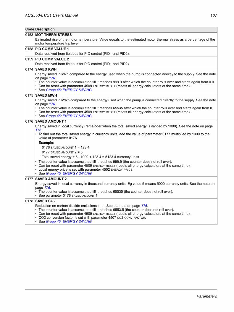
ACS550-01/U1 User’s Manual 107
0153 MOT THERM STRESSEstimated rise of the motor temperature. Value equals to the estimated motor thermal stress as a percentage of the motor temperature trip level.
0158 PID COMM VALUE 1Data received from fieldbus for PID control (PID1 and PID2).
0159 PID COMM VALUE 2Data received from fieldbus for PID control (PID1 and PID2).
0174 SAVED KWHEnergy saved in kWh compared to the energy used when the pump is connected directly to the supply. See the note on page 176.• The counter value is accumulated till it reaches 999.9 after which the counter rolls over and starts again from 0.0.• Can be reset with parameter 4509 ENERGY RESET (resets all energy calculators at the same time).• See Group 45: ENERGY SAVING.
0175 SAVED MWHEnergy saved in MWh compared to the energy used when the pump is connected directly to the supply. See the note on page 176.• The counter value is accumulated till it reaches 65535 after which the counter rolls over and starts again from 0. • Can be reset with parameter 4509 ENERGY RESET (resets all energy calculators at the same time). • See Group 45: ENERGY SAVING.
0176 SAVED AMOUNT 1Energy saved in local currency (remainder when the total saved energy is divided by 1000). See the note on page 176.• To find out the total saved energy in currency units, add the value of parameter 0177 multiplied by 1000 to the
value of parameter 0176.Example:
0176 SAVED AMOUNT 1 = 123.40177 SAVED AMOUNT 2 = 5Total saved energy = 5 · 1000 + 123.4 = 5123.4 currency units.
• The counter value is accumulated till it reaches 999.9 (the counter does not roll over). • Can be reset with parameter 4509 ENERGY RESET (resets all energy calculators at the same time). • Local energy price is set with parameter 4502 ENERGY PRICE. • See Group 45: ENERGY SAVING.
0177 SAVED AMOUNT 2Energy saved in local currency in thousand currency units. Eg value 5 means 5000 currency units. See the note on page 176.• The counter value is accumulated till it reaches 65535 (the counter does not roll over). • See parameter 0176 SAVED AMOUNT 1.
0178 SAVED CO2Reduction on carbon dioxide emissions in tn. See the note on page 176.• The counter value is accumulated till it reaches 6553.5 (the counter does not roll over). • Can be reset with parameter 4509 ENERGY RESET (resets all energy calculators at the same time). • CO2 conversion factor is set with parameter 4507 CO2 CONV FACTOR. • See Group 45: ENERGY SAVING.
Code Description
Parameters
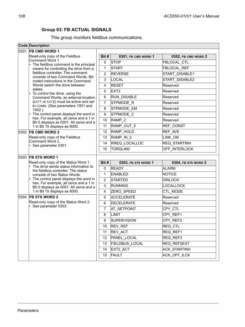
108 ACS550-01/U1 User’s Manual
Group 03: FB ACTUAL SIGNALSThis group monitors fieldbus communications.
Code Description0301 FB CMD WORD 1
Read-only copy of the Fieldbus Command Word 1. • The fieldbus command is the principal
means for controlling the drive from a fieldbus controller. The command consists of two Command Words. Bit-coded instructions in the Command Words switch the drive between states.
• To control the drive, using the Command Words, an external location (EXT1 or EXT2) must be active and set to COMM. (See parameters 1001 and 1002.)
• The control panel displays the word in hex. For example, all zeros and a 1 in Bit 0 displays as 0001. All zeros and a 1 in Bit 15 displays as 8000.
0302 FB CMD WORD 2Read-only copy of the Fieldbus Command Word 2. • See parameter 0301.
0303 FB STS WORD 1Read-only copy of the Status Word 1. • The drive sends status information to
the fieldbus controller. The status consists of two Status Words.
• The control panel displays the word in hex. For example, all zeros and a 1 in Bit 0 displays as 0001. All zeros and a 1 in Bit 15 displays as 8000.
0304 FB STS WORD 2Read-only copy of the Status Word 2. • See parameter 0303.
Bit # 0301, FB CMD WORD 1 0302, FB CMD WORD 20 STOP FBLOCAL_CTL1 START FBLOCAL_REF2 REVERSE START_DISABLE13 LOCAL START_DISABLE24 RESET Reserved5 EXT2 Reserved6 RUN_DISABLE Reserved7 STPMODE_R Reserved8 STPMODE_EM Reserved9 STPMODE_C Reserved
10 RAMP_2 Reserved11 RAMP_OUT_0 REF_CONST12 RAMP_HOLD REF_AVE13 RAMP_IN_0 LINK_ON14 RREQ_LOCALLOC REQ_STARTINH15 TORQLIM2 OFF_INTERLOCK
Bit # 0303, FB STS WORD 1 0304, FB STS WORD 20 READY ALARM1 ENABLED NOTICE2 STARTED DIRLOCK3 RUNNING LOCALLOCK4 ZERO_SPEED CTL_MODE5 ACCELERATE Reserved6 DECELERATE Reserved7 AT_SETPOINT CPY_CTL8 LIMIT CPY_REF19 SUPERVISION CPY_REF2
10 REV_REF REQ_CTL11 REV_ACT REQ_REF112 PANEL_LOCAL REQ_REF213 FIELDBUS_LOCAL REQ_REF2EXT14 EXT2_ACT ACK_STARTINH15 FAULT ACK_OFF_ILCK
Parameters
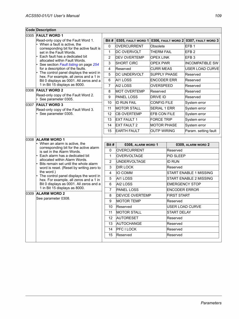
ACS550-01/U1 User’s Manual 109
0305 FAULT WORD 1Read-only copy of the Fault Word 1.• When a fault is active, the
corresponding bit for the active fault is set in the Fault Words.
• Each fault has a dedicated bit allocated within Fault Words.
• See section Fault listing on page 254 for a description of the faults.
• The control panel displays the word in hex. For example, all zeros and a 1 in Bit 0 displays as 0001. All zeros and a 1 in Bit 15 displays as 8000.
0306 FAULT WORD 2Read-only copy of the Fault Word 2.• See parameter 0305.
0307 FAULT WORD 3Read-only copy of the Fault Word 3.• See parameter 0305.
0308 ALARM WORD 1• When an alarm is active, the
corresponding bit for the active alarm is set in the Alarm Words.
• Each alarm has a dedicated bit allocated within Alarm Words.
• Bits remain set until the whole alarm word is reset. (Reset by writing zero to the word.)
• The control panel displays the word in hex. For example, all zeros and a 1 in Bit 0 displays as 0001. All zeros and a 1 in Bit 15 displays as 8000.
0309 ALARM WORD 2See parameter 0308.
Code Description
Bit # 0305, FAULT WORD 1 0306, FAULT WORD 2 0307, FAULT WORD 30 OVERCURRENT Obsolete EFB 1 1 DC OVERVOLT THERM FAIL EFB 2 2 DEV OVERTEMP OPEX LINK EFB 3 3 SHORT CIRC OPEX PWR INCOMPATIBLE SW4 Reserved CURR MEAS USER LOAD CURVE5 DC UNDERVOLT SUPPLY PHASE Reserved 6 AI1 LOSS ENCODER ERR Reserved 7 AI2 LOSS OVERSPEED Reserved 8 MOT OVERTEMP Reserved Reserved 9 PANEL LOSS DRIVE ID Reserved
10 ID RUN FAIL CONFIG FILE System error 11 MOTOR STALL SERIAL 1 ERR System error 12 CB OVERTEMP EFB CON FILE System error 13 EXT FAULT 1 FORCE TRIP System error 14 EXT FAULT 2 MOTOR PHASE System error 15 EARTH FAULT OUTP WIRING Param. setting fault
Bit # 0308, ALARM WORD 1 0309, ALARM WORD 20 OVERCURRENT Reserved1 OVERVOLTAGE PID SLEEP 2 UNDERVOLTAGE ID RUN 3 DIR LOCK Reserved4 IO COMM START ENABLE 1 MISSING5 AI1 LOSS START ENABLE 2 MISSING6 AI2 LOSS EMERGENCY STOP7 PANEL LOSS ENCODER ERROR8 DEVICE OVERTEMP FIRST START9 MOTOR TEMP Reserved10 Reserved USER LOAD CURVE11 MOTOR STALL START DELAY12 AUTORESET Reserved13 AUTOCHANGE Reserved14 PFC I LOCK Reserved15 Reserved Reserved
Parameters
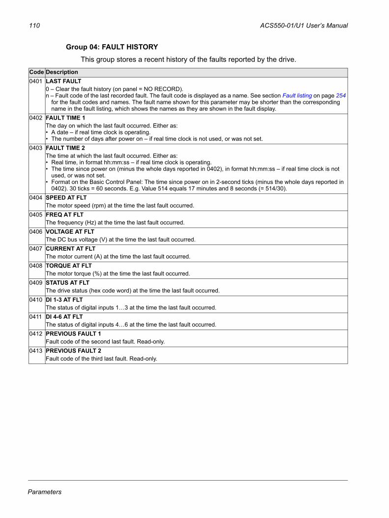
110 ACS550-01/U1 User’s Manual
Group 04: FAULT HISTORYThis group stores a recent history of the faults reported by the drive.
Code Description0401 LAST FAULT
0 – Clear the fault history (on panel = NO RECORD).n – Fault code of the last recorded fault. The fault code is displayed as a name. See section Fault listing on page 254
for the fault codes and names. The fault name shown for this parameter may be shorter than the corresponding name in the fault listing, which shows the names as they are shown in the fault display.
0402 FAULT TIME 1The day on which the last fault occurred. Either as:• A date – if real time clock is operating.• The number of days after power on – if real time clock is not used, or was not set.
0403 FAULT TIME 2The time at which the last fault occurred. Either as:• Real time, in format hh:mm:ss – if real time clock is operating.• The time since power on (minus the whole days reported in 0402), in format hh:mm:ss – if real time clock is not
used, or was not set.• Format on the Basic Control Panel: The time since power on in 2-second ticks (minus the whole days reported in
0402). 30 ticks = 60 seconds. E.g. Value 514 equals 17 minutes and 8 seconds (= 514/30).0404 SPEED AT FLT
The motor speed (rpm) at the time the last fault occurred.0405 FREQ AT FLT
The frequency (Hz) at the time the last fault occurred.0406 VOLTAGE AT FLT
The DC bus voltage (V) at the time the last fault occurred.0407 CURRENT AT FLT
The motor current (A) at the time the last fault occurred.0408 TORQUE AT FLT
The motor torque (%) at the time the last fault occurred.0409 STATUS AT FLT
The drive status (hex code word) at the time the last fault occurred.0410 DI 1-3 AT FLT
The status of digital inputs 1…3 at the time the last fault occurred.0411 DI 4-6 AT FLT
The status of digital inputs 4…6 at the time the last fault occurred.0412 PREVIOUS FAULT 1
Fault code of the second last fault. Read-only.0413 PREVIOUS FAULT 2
Fault code of the third last fault. Read-only.
Parameters
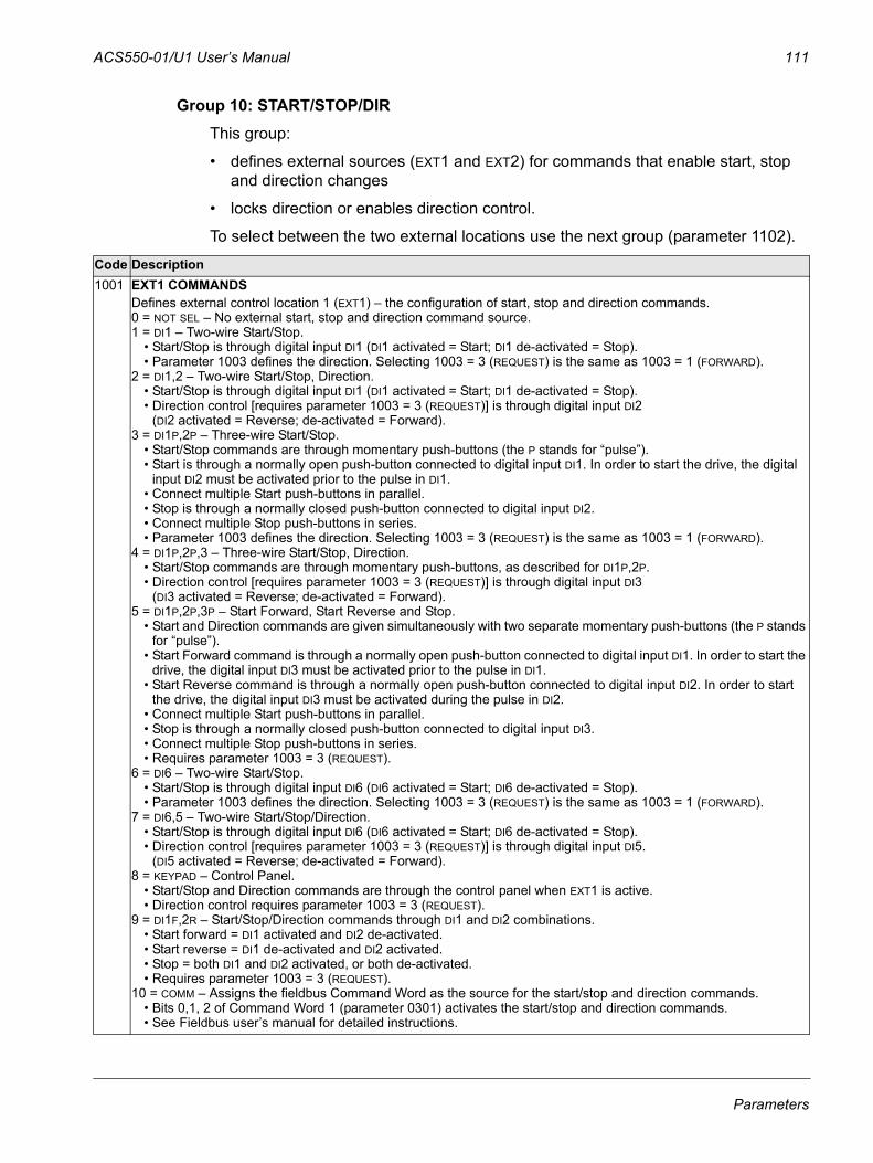
ACS550-01/U1 User’s Manual 111
Group 10: START/STOP/DIRThis group:
• defines external sources (EXT1 and EXT2) for commands that enable start, stop and direction changes
• locks direction or enables direction control.
To select between the two external locations use the next group (parameter 1102).
Code Description1001 EXT1 COMMANDS
Defines external control location 1 (EXT1) – the configuration of start, stop and direction commands.0 = NOT SEL – No external start, stop and direction command source.1 = DI1 – Two-wire Start/Stop.
• Start/Stop is through digital input DI1 (DI1 activated = Start; DI1 de-activated = Stop).• Parameter 1003 defines the direction. Selecting 1003 = 3 (REQUEST) is the same as 1003 = 1 (FORWARD).
2 = DI1,2 – Two-wire Start/Stop, Direction. • Start/Stop is through digital input DI1 (DI1 activated = Start; DI1 de-activated = Stop).• Direction control [requires parameter 1003 = 3 (REQUEST)] is through digital input DI2
(DI2 activated = Reverse; de-activated = Forward). 3 = DI1P,2P – Three-wire Start/Stop.
• Start/Stop commands are through momentary push-buttons (the P stands for “pulse”). • Start is through a normally open push-button connected to digital input DI1. In order to start the drive, the digital
input DI2 must be activated prior to the pulse in DI1.• Connect multiple Start push-buttons in parallel.• Stop is through a normally closed push-button connected to digital input DI2. • Connect multiple Stop push-buttons in series. • Parameter 1003 defines the direction. Selecting 1003 = 3 (REQUEST) is the same as 1003 = 1 (FORWARD).
4 = DI1P,2P,3 – Three-wire Start/Stop, Direction.• Start/Stop commands are through momentary push-buttons, as described for DI1P,2P.• Direction control [requires parameter 1003 = 3 (REQUEST)] is through digital input DI3
(DI3 activated = Reverse; de-activated = Forward). 5 = DI1P,2P,3P – Start Forward, Start Reverse and Stop.
• Start and Direction commands are given simultaneously with two separate momentary push-buttons (the P stands for “pulse”).
• Start Forward command is through a normally open push-button connected to digital input DI1. In order to start the drive, the digital input DI3 must be activated prior to the pulse in DI1.
• Start Reverse command is through a normally open push-button connected to digital input DI2. In order to start the drive, the digital input DI3 must be activated during the pulse in DI2.
• Connect multiple Start push-buttons in parallel.• Stop is through a normally closed push-button connected to digital input DI3. • Connect multiple Stop push-buttons in series. • Requires parameter 1003 = 3 (REQUEST).
6 = DI6 – Two-wire Start/Stop.• Start/Stop is through digital input DI6 (DI6 activated = Start; DI6 de-activated = Stop).• Parameter 1003 defines the direction. Selecting 1003 = 3 (REQUEST) is the same as 1003 = 1 (FORWARD).
7 = DI6,5 – Two-wire Start/Stop/Direction. • Start/Stop is through digital input DI6 (DI6 activated = Start; DI6 de-activated = Stop).• Direction control [requires parameter 1003 = 3 (REQUEST)] is through digital input DI5.
(DI5 activated = Reverse; de-activated = Forward). 8 = KEYPAD – Control Panel.
• Start/Stop and Direction commands are through the control panel when EXT1 is active. • Direction control requires parameter 1003 = 3 (REQUEST).
9 = DI1F,2R – Start/Stop/Direction commands through DI1 and DI2 combinations.• Start forward = DI1 activated and DI2 de-activated. • Start reverse = DI1 de-activated and DI2 activated.• Stop = both DI1 and DI2 activated, or both de-activated.• Requires parameter 1003 = 3 (REQUEST).
10 = COMM – Assigns the fieldbus Command Word as the source for the start/stop and direction commands.• Bits 0,1, 2 of Command Word 1 (parameter 0301) activates the start/stop and direction commands.• See Fieldbus user’s manual for detailed instructions.
Parameters
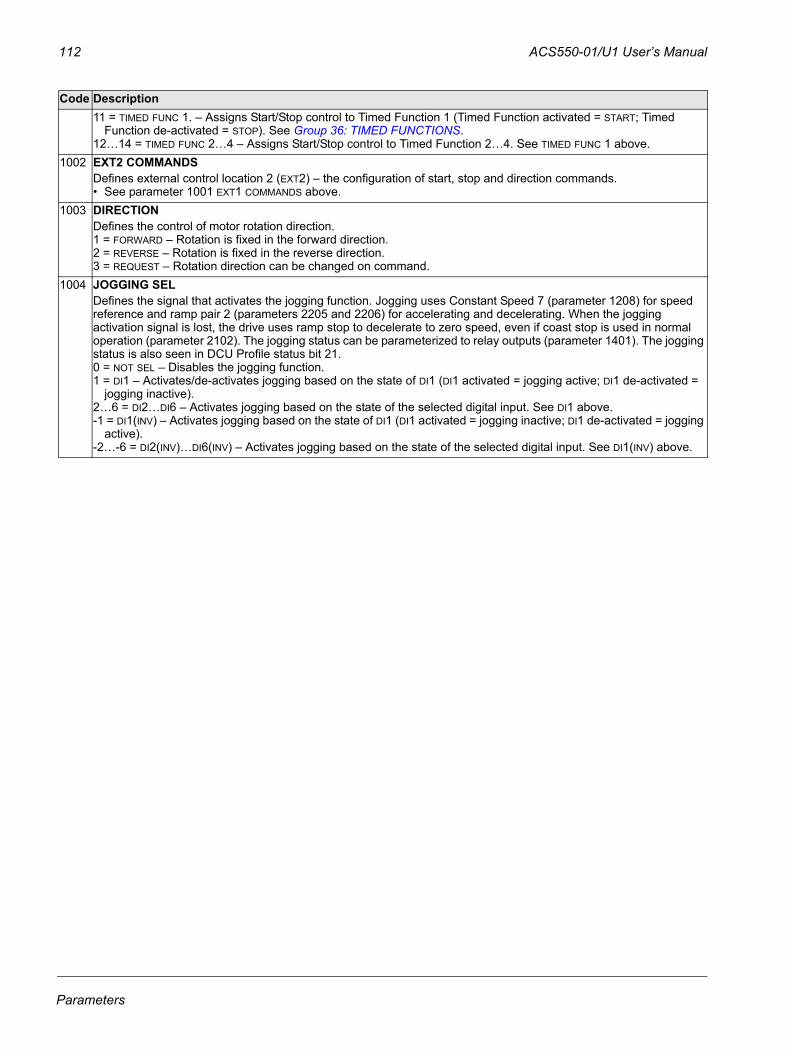
112 ACS550-01/U1 User’s Manual
11 = TIMED FUNC 1. – Assigns Start/Stop control to Timed Function 1 (Timed Function activated = START; Timed Function de-activated = STOP). See Group 36: TIMED FUNCTIONS.
12…14 = TIMED FUNC 2…4 – Assigns Start/Stop control to Timed Function 2…4. See TIMED FUNC 1 above.1002 EXT2 COMMANDS
Defines external control location 2 (EXT2) – the configuration of start, stop and direction commands. • See parameter 1001 EXT1 COMMANDS above.
1003 DIRECTIONDefines the control of motor rotation direction.1 = FORWARD – Rotation is fixed in the forward direction.2 = REVERSE – Rotation is fixed in the reverse direction.3 = REQUEST – Rotation direction can be changed on command.
1004 JOGGING SELDefines the signal that activates the jogging function. Jogging uses Constant Speed 7 (parameter 1208) for speed reference and ramp pair 2 (parameters 2205 and 2206) for accelerating and decelerating. When the jogging activation signal is lost, the drive uses ramp stop to decelerate to zero speed, even if coast stop is used in normal operation (parameter 2102). The jogging status can be parameterized to relay outputs (parameter 1401). The jogging status is also seen in DCU Profile status bit 21.0 = NOT SEL – Disables the jogging function.1 = DI1 – Activates/de-activates jogging based on the state of DI1 (DI1 activated = jogging active; DI1 de-activated =
jogging inactive).2…6 = DI2…DI6 – Activates jogging based on the state of the selected digital input. See DI1 above.-1 = DI1(INV) – Activates jogging based on the state of DI1 (DI1 activated = jogging inactive; DI1 de-activated = jogging
active).-2…-6 = DI2(INV)…DI6(INV) – Activates jogging based on the state of the selected digital input. See DI1(INV) above.
Code Description
Parameters
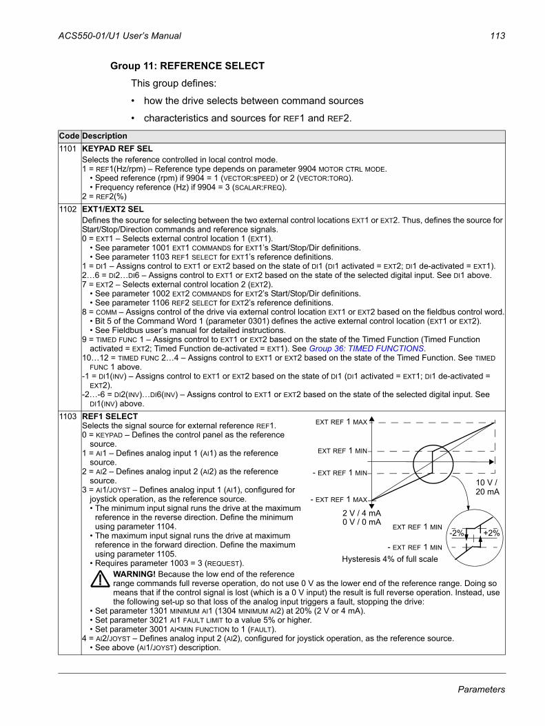
ACS550-01/U1 User’s Manual 113
Group 11: REFERENCE SELECTThis group defines:
• how the drive selects between command sources
• characteristics and sources for REF1 and REF2.
Code Description1101 KEYPAD REF SEL
Selects the reference controlled in local control mode.1 = REF1(Hz/rpm) – Reference type depends on parameter 9904 MOTOR CTRL MODE.
• Speed reference (rpm) if 9904 = 1 (VECTOR:sPEED) or 2 (VECTOR:TORQ).• Frequency reference (Hz) if 9904 = 3 (SCALAR:FREQ).
2 = REF2(%)1102 EXT1/EXT2 SEL
Defines the source for selecting between the two external control locations EXT1 or EXT2. Thus, defines the source for Start/Stop/Direction commands and reference signals.0 = EXT1 – Selects external control location 1 (EXT1).
• See parameter 1001 EXT1 COMMANDS for EXT1’s Start/Stop/Dir definitions.• See parameter 1103 REF1 SELECT for EXT1’s reference definitions.
1 = DI1 – Assigns control to EXT1 or EXT2 based on the state of DI1 (DI1 activated = EXT2; DI1 de-activated = EXT1).2…6 = DI2…DI6 – Assigns control to EXT1 or EXT2 based on the state of the selected digital input. See DI1 above.7 = EXT2 – Selects external control location 2 (EXT2).
• See parameter 1002 EXT2 COMMANDS for EXT2’s Start/Stop/Dir definitions.• See parameter 1106 REF2 SELECT for EXT2’s reference definitions.
8 = COMM – Assigns control of the drive via external control location EXT1 or EXT2 based on the fieldbus control word.• Bit 5 of the Command Word 1 (parameter 0301) defines the active external control location (EXT1 or EXT2).• See Fieldbus user’s manual for detailed instructions.
9 = TIMED FUNC 1 – Assigns control to EXT1 or EXT2 based on the state of the Timed Function (Timed Function activated = EXT2; Timed Function de-activated = EXT1). See Group 36: TIMED FUNCTIONS.
10…12 = TIMED FUNC 2…4 – Assigns control to EXT1 or EXT2 based on the state of the Timed Function. See TIMED FUNC 1 above.
-1 = DI1(INV) – Assigns control to EXT1 or EXT2 based on the state of DI1 (DI1 activated = EXT1; DI1 de-activated = EXT2).
-2…-6 = DI2(INV)…DI6(INV) – Assigns control to EXT1 or EXT2 based on the state of the selected digital input. See DI1(INV) above.
1103 REF1 SELECTSelects the signal source for external reference REF1.0 = KEYPAD – Defines the control panel as the reference
source.1 = AI1 – Defines analog input 1 (AI1) as the reference
source.2 = AI2 – Defines analog input 2 (AI2) as the reference
source.3 = AI1/JOYST – Defines analog input 1 (AI1), configured for
joystick operation, as the reference source.• The minimum input signal runs the drive at the maximum
reference in the reverse direction. Define the minimum using parameter 1104.
• The maximum input signal runs the drive at maximum reference in the forward direction. Define the maximum using parameter 1105.
• Requires parameter 1003 = 3 (REQUEST).WARNING! Because the low end of the reference range commands full reverse operation, do not use 0 V as the lower end of the reference range. Doing so means that if the control signal is lost (which is a 0 V input) the result is full reverse operation. Instead, use the following set-up so that loss of the analog input triggers a fault, stopping the drive:
• Set parameter 1301 MINIMUM AI1 (1304 MINIMUM AI2) at 20% (2 V or 4 mA). • Set parameter 3021 AI1 FAULT LIMIT to a value 5% or higher.• Set parameter 3001 AI<MIN FUNCTION to 1 (FAULT).
4 = AI2/JOYST – Defines analog input 2 (AI2), configured for joystick operation, as the reference source.• See above (AI1/JOYST) description.
+2%-2%
10 V /
Hysteresis 4% of full scale
EXT REF 1 MIN
- EXT REF 1 MIN
- EXT REF 1 MAX
EXT REF 1 MIN
EXT REF 1 MAX
- EXT REF 1 MIN
2 V / 4 mA0 V / 0 mA
20 mA
Parameters
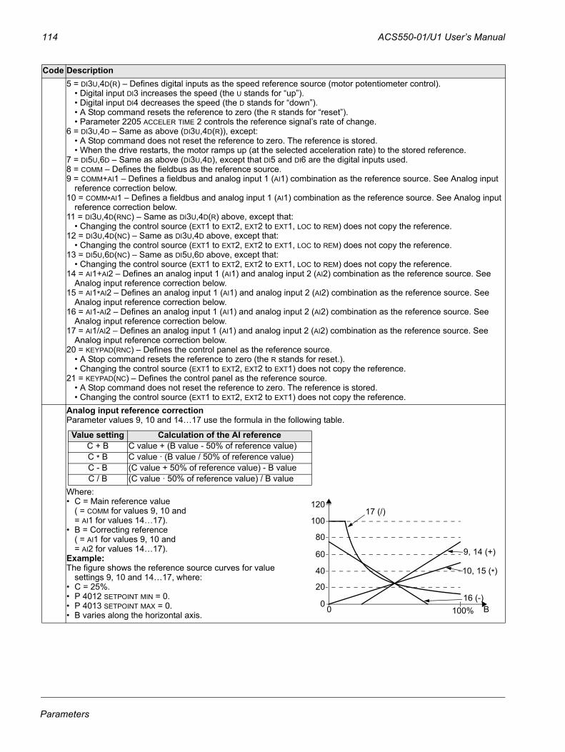
114 ACS550-01/U1 User’s Manual
5 = DI3U,4D(R) – Defines digital inputs as the speed reference source (motor potentiometer control). • Digital input DI3 increases the speed (the U stands for “up”).• Digital input DI4 decreases the speed (the D stands for “down”).• A Stop command resets the reference to zero (the R stands for “reset”). • Parameter 2205 ACCELER TIME 2 controls the reference signal’s rate of change.
6 = DI3U,4D – Same as above (DI3U,4D(R)), except:• A Stop command does not reset the reference to zero. The reference is stored.• When the drive restarts, the motor ramps up (at the selected acceleration rate) to the stored reference.
7 = DI5U,6D – Same as above (DI3U,4D), except that DI5 and DI6 are the digital inputs used.8 = COMM – Defines the fieldbus as the reference source.9 = COMM+AI1 – Defines a fieldbus and analog input 1 (AI1) combination as the reference source. See Analog input
reference correction below.10 = COMM*AI1 – Defines a fieldbus and analog input 1 (AI1) combination as the reference source. See Analog input
reference correction below.11 = DI3U,4D(RNC) – Same as DI3U,4D(R) above, except that:
• Changing the control source (EXT1 to EXT2, EXT2 to EXT1, LOC to REM) does not copy the reference. 12 = DI3U,4D(NC) – Same as DI3U,4D above, except that:
• Changing the control source (EXT1 to EXT2, EXT2 to EXT1, LOC to REM) does not copy the reference. 13 = DI5U,6D(NC) – Same as DI5U,6D above, except that:
• Changing the control source (EXT1 to EXT2, EXT2 to EXT1, LOC to REM) does not copy the reference. 14 = AI1+AI2 – Defines an analog input 1 (AI1) and analog input 2 (AI2) combination as the reference source. See
Analog input reference correction below.15 = AI1*AI2 – Defines an analog input 1 (AI1) and analog input 2 (AI2) combination as the reference source. See
Analog input reference correction below.16 = AI1-AI2 – Defines an analog input 1 (AI1) and analog input 2 (AI2) combination as the reference source. See
Analog input reference correction below.17 = AI1/AI2 – Defines an analog input 1 (AI1) and analog input 2 (AI2) combination as the reference source. See
Analog input reference correction below.20 = KEYPAD(RNC) – Defines the control panel as the reference source.
• A Stop command resets the reference to zero (the R stands for reset.).• Changing the control source (EXT1 to EXT2, EXT2 to EXT1) does not copy the reference.
21 = KEYPAD(NC) – Defines the control panel as the reference source. • A Stop command does not reset the reference to zero. The reference is stored.• Changing the control source (EXT1 to EXT2, EXT2 to EXT1) does not copy the reference.
Analog input reference correctionParameter values 9, 10 and 14…17 use the formula in the following table.
Where:• C = Main reference value
( = COMM for values 9, 10 and = AI1 for values 14…17).
• B = Correcting reference ( = AI1 for values 9, 10 and = AI2 for values 14…17).
Example:The figure shows the reference source curves for value
settings 9, 10 and 14…17, where:• C = 25%.• P 4012 SETPOINT MIN = 0.• P 4013 SETPOINT MAX = 0.• B varies along the horizontal axis.
Code Description
Value setting Calculation of the AI referenceC + B C value + (B value - 50% of reference value)C * B C value · (B value / 50% of reference value)C - B (C value + 50% of reference value) - B valueC / B (C value · 50% of reference value) / B value
120
100
80
60
40
20
0 0 100%
9, 14 (+)
16 (-)
10, 15 (*)
17 (/)
B
Parameters
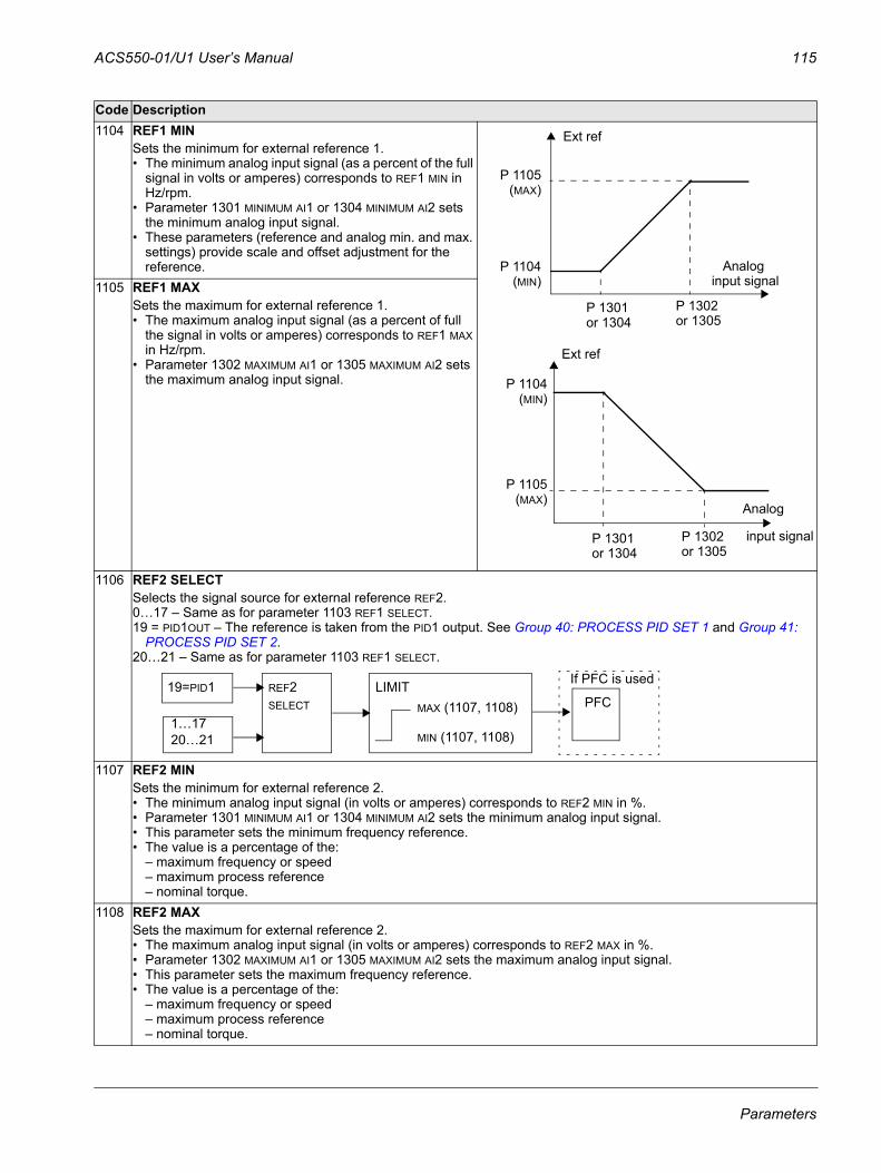
ACS550-01/U1 User’s Manual 115
1104 REF1 MINSets the minimum for external reference 1. • The minimum analog input signal (as a percent of the full
signal in volts or amperes) corresponds to REF1 MIN in Hz/rpm.
• Parameter 1301 MINIMUM AI1 or 1304 MINIMUM AI2 sets the minimum analog input signal.
• These parameters (reference and analog min. and max. settings) provide scale and offset adjustment for the reference.
1105 REF1 MAXSets the maximum for external reference 1. • The maximum analog input signal (as a percent of full
the signal in volts or amperes) corresponds to REF1 MAX in Hz/rpm.
• Parameter 1302 MAXIMUM AI1 or 1305 MAXIMUM AI2 sets the maximum analog input signal.
1106 REF2 SELECTSelects the signal source for external reference REF2.0…17 – Same as for parameter 1103 REF1 SELECT. 19 = PID1OUT – The reference is taken from the PID1 output. See Group 40: PROCESS PID SET 1 and Group 41:
PROCESS PID SET 2.20…21 – Same as for parameter 1103 REF1 SELECT.
1107 REF2 MINSets the minimum for external reference 2. • The minimum analog input signal (in volts or amperes) corresponds to REF2 MIN in %.• Parameter 1301 MINIMUM AI1 or 1304 MINIMUM AI2 sets the minimum analog input signal.• This parameter sets the minimum frequency reference. • The value is a percentage of the:
– maximum frequency or speed – maximum process reference– nominal torque.
1108 REF2 MAXSets the maximum for external reference 2. • The maximum analog input signal (in volts or amperes) corresponds to REF2 MAX in %.• Parameter 1302 MAXIMUM AI1 or 1305 MAXIMUM AI2 sets the maximum analog input signal.• This parameter sets the maximum frequency reference. • The value is a percentage of the:
– maximum frequency or speed– maximum process reference– nominal torque.
Code Description
Ext ref
Analog
P 1105
P 1104
P 1301 P 1302
input signal
P 1301 P 1302 input signal
Analog
Ext ref
or 1304 or 1305
or 1304 or 1305
(MAX)
(MIN)
P 1105
P 1104
(MAX)
(MIN)
19=PID1 REF2SELECT
LIMITMAX (1107, 1108)
MIN (1107, 1108)
PFC
If PFC is used
1…1720…21
Parameters
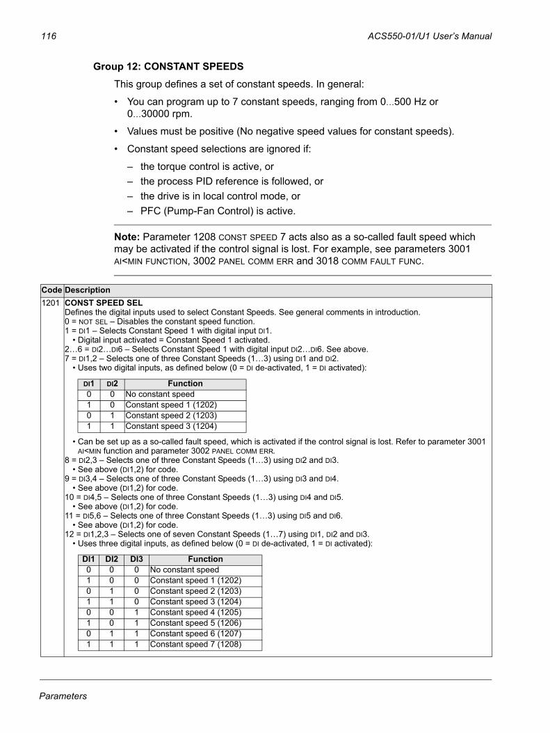
116 ACS550-01/U1 User’s Manual
Group 12: CONSTANT SPEEDSThis group defines a set of constant speeds. In general:
• You can program up to 7 constant speeds, ranging from 0…500 Hz or 0…30000 rpm.
• Values must be positive (No negative speed values for constant speeds).
• Constant speed selections are ignored if:
– the torque control is active, or– the process PID reference is followed, or– the drive is in local control mode, or– PFC (Pump-Fan Control) is active.
Note: Parameter 1208 CONST SPEED 7 acts also as a so-called fault speed which may be activated if the control signal is lost. For example, see parameters 3001 AI<MIN FUNCTION, 3002 PANEL COMM ERR and 3018 COMM FAULT FUNC.
Code Description1201 CONST SPEED SEL
Defines the digital inputs used to select Constant Speeds. See general comments in introduction.0 = NOT SEL – Disables the constant speed function.1 = DI1 – Selects Constant Speed 1 with digital input DI1.
• Digital input activated = Constant Speed 1 activated.2…6 = DI2…DI6 – Selects Constant Speed 1 with digital input DI2…DI6. See above.7 = DI1,2 – Selects one of three Constant Speeds (1…3) using DI1 and DI2.
• Uses two digital inputs, as defined below (0 = DI de-activated, 1 = DI activated):
• Can be set up as a so-called fault speed, which is activated if the control signal is lost. Refer to parameter 3001 AI<MIN function and parameter 3002 PANEL COMM ERR.
8 = DI2,3 – Selects one of three Constant Speeds (1…3) using DI2 and DI3.• See above (DI1,2) for code.
9 = DI3,4 – Selects one of three Constant Speeds (1…3) using DI3 and DI4.• See above (DI1,2) for code.
10 = DI4,5 – Selects one of three Constant Speeds (1…3) using DI4 and DI5.• See above (DI1,2) for code.
11 = DI5,6 – Selects one of three Constant Speeds (1…3) using DI5 and DI6.• See above (DI1,2) for code.
12 = DI1,2,3 – Selects one of seven Constant Speeds (1…7) using DI1, DI2 and DI3.• Uses three digital inputs, as defined below (0 = DI de-activated, 1 = DI activated):
DI1 DI2 Function0 0 No constant speed1 0 Constant speed 1 (1202)0 1 Constant speed 2 (1203)1 1 Constant speed 3 (1204)
DI1 DI2 DI3 Function0 0 0 No constant speed1 0 0 Constant speed 1 (1202)0 1 0 Constant speed 2 (1203)1 1 0 Constant speed 3 (1204)0 0 1 Constant speed 4 (1205)1 0 1 Constant speed 5 (1206)0 1 1 Constant speed 6 (1207)1 1 1 Constant speed 7 (1208)
Parameters
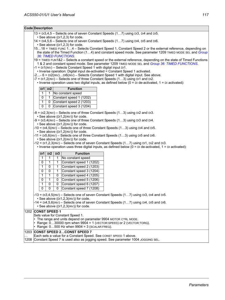
ACS550-01/U1 User’s Manual 117
13 = DI3,4,5 – Selects one of seven Constant Speeds (1…7) using DI3, DI4 and DI5.• See above (DI1,2,3) for code.
14 = DI4,5,6 – Selects one of seven Constant Speeds (1…7) using DI4, DI5 and DI6.• See above (DI1,2,3) for code.
15…18 = TIMED FUNC 1…4 – Selects Constant Speed 1, Constant Speed 2 or the external reference, depending on the state of the Timed Function (1…4) and constant speed mode. See parameter 1209 TIMED MODE SEL and Group 36: TIMED FUNCTIONS.
19 = TIMED FUN1&2 – Selects a constant speed or the external reference, depending on the state of Timed Functions 1 & 2 and constant speed mode. See parameter 1209 TIMED MODE SEL and Group 36: TIMED FUNCTIONS.
-1 = DI1(INV) – Selects Constant Speed 1 with digital input DI1. • Inverse operation: Digital input de-activated = Constant Speed 1 activated.
-2…- 6 = DI2(INV)…DI6(INV) – Selects Constant Speed 1 with digital input. See above.-7 = DI1,2(INV) – Selects one of three Constant Speeds (1…3) using DI1 and DI2.
• Inverse operation uses two digital inputs, as defined below (0 = DI de-activated, 1 = DI activated):
-8 = DI2,3(INV) – Selects one of three Constant Speeds (1…3) using DI2 and DI3.• See above (DI1,2(INV)) for code.
-9 = DI3,4(INV) – Selects one of three Constant Speeds (1…3) using DI3 and DI4.• See above (DI1,2(INV)) for code.
-10 = DI4,5(INV) – Selects one of three Constant Speeds (1…3) using DI4 and DI5.• See above (DI1,2(INV)) for code.
-11 = DI5,6(INV) – Selects one of three Constant Speeds (1…3) using DI5 and DI6.• See above (DI1,2(INV)) for code.
-12 = DI1,2,3(INV) – Selects one of seven Constant Speeds (1…7) using DI1, DI2 and DI3.• Inverse operation uses three digital inputs, as defined below (0 = DI de-activated, 1 = DI activated):
-13 = DI3,4,5(INV) – Selects one of seven Constant Speeds (1…7) using DI3, DI4 and DI5.• See above (DI1,2,3(INV)) for code.
-14 = DI4,5,6(INV) – Selects one of seven Constant Speeds (1…7) using DI4, DI5 and DI6.• See above (DI1,2,3(INV)) for code.
1202 CONST SPEED 1Sets value for Constant Speed 1. • The range and units depend on parameter 9904 MOTOR CTRL MODE. • Range: 0…30000 rpm when 9904 = 1 (VECTOR:SPEED) or 2 (VECTOR:TORQ).• Range: 0…500 Hz when 9904 = 3 (SCALAR:FREQ).
1203…1208
CONST SPEED 2…CONST SPEED 7Each sets a value for a Constant Speed. See CONST SPEED 1 above.Constant Speed 7 is used also as jogging speed. See parameter 1004 JOGGING SEL.
Code Description
DI1 DI2 Function1 1 No constant speed0 1 Constant speed 1 (1202)1 0 Constant speed 2 (1203)0 0 Constant speed 3 (1204)
DI1 DI2 DI3 Function1 1 1 No constant speed0 1 1 Constant speed 1 (1202)1 0 1 Constant speed 2 (1203)0 0 1 Constant speed 3 (1204)1 1 0 Constant speed 4 (1205)0 1 0 Constant speed 5 (1206)1 0 0 Constant speed 6 (1207)0 0 0 Constant speed 7 (1208)
Parameters
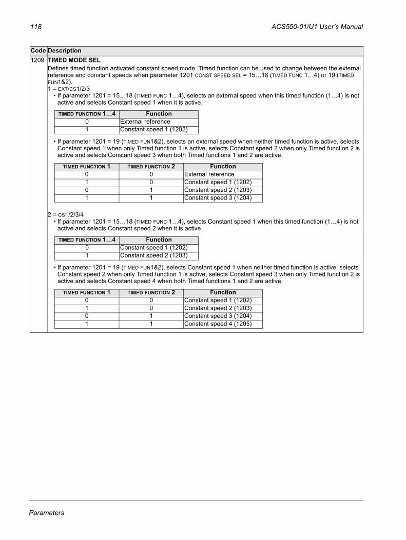
118 ACS550-01/U1 User’s Manual
1209 TIMED MODE SEL Defines timed function activated constant speed mode. Timed function can be used to change between the external reference and constant speeds when parameter 1201 CONST SPEED SEL = 15…18 (TIMED FUNC 1…4) or 19 (TIMED FUN1&2).1 = EXT/CS1/2/3
• If parameter 1201 = 15…18 (TIMED FUNC 1…4), selects an external speed when this timed function (1…4) is not active and selects Constant speed 1 when it is active.
• If parameter 1201 = 19 (TIMED FUN1&2), selects an external speed when neither timed function is active, selects Constant speed 1 when only Timed function 1 is active, selects Constant speed 2 when only Timed function 2 is active and selects Constant speed 3 when both Timed functions 1 and 2 are active.
2 = CS1/2/3/4• If parameter 1201 = 15…18 (TIMED FUNC 1…4), selects Constant speed 1 when this timed function (1…4) is not
active and selects Constant speed 2 when it is active.
• If parameter 1201 = 19 (TIMED FUN1&2), selects Constant speed 1 when neither timed function is active, selects Constant speed 2 when only Timed function 1 is active, selects Constant speed 3 when only Timed function 2 is active and selects Constant speed 4 when both Timed functions 1 and 2 are active.
Code Description
TIMED FUNCTION 1…4 Function0 External reference1 Constant speed 1 (1202)
TIMED FUNCTION 1 TIMED FUNCTION 2 Function0 0 External reference1 0 Constant speed 1 (1202)0 1 Constant speed 2 (1203)1 1 Constant speed 3 (1204)
TIMED FUNCTION 1…4 Function0 Constant speed 1 (1202)1 Constant speed 2 (1203)
TIMED FUNCTION 1 TIMED FUNCTION 2 Function0 0 Constant speed 1 (1202)1 0 Constant speed 2 (1203)0 1 Constant speed 3 (1204)1 1 Constant speed 4 (1205)
Parameters
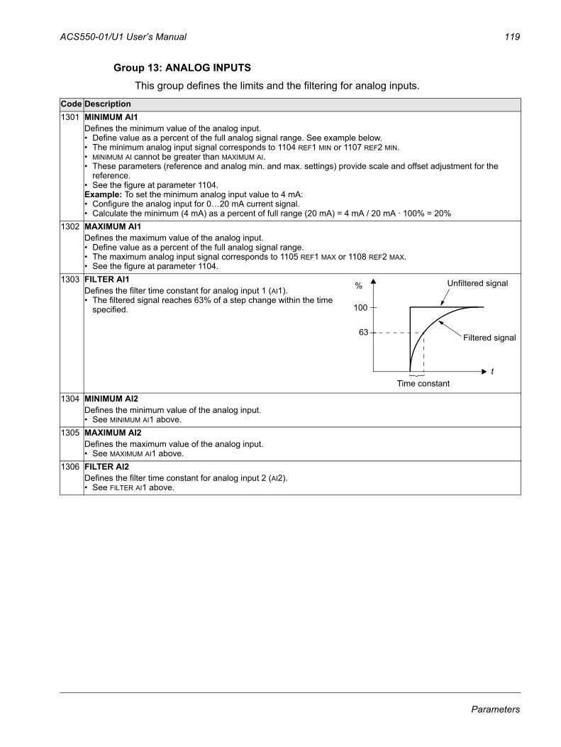
ACS550-01/U1 User’s Manual 119
Group 13: ANALOG INPUTSThis group defines the limits and the filtering for analog inputs.
Code Description1301 MINIMUM AI1
Defines the minimum value of the analog input.• Define value as a percent of the full analog signal range. See example below.• The minimum analog input signal corresponds to 1104 REF1 MIN or 1107 REF2 MIN.• MINIMUM AI cannot be greater than MAXIMUM AI.• These parameters (reference and analog min. and max. settings) provide scale and offset adjustment for the
reference.• See the figure at parameter 1104.Example: To set the minimum analog input value to 4 mA:• Configure the analog input for 0…20 mA current signal.• Calculate the minimum (4 mA) as a percent of full range (20 mA) = 4 mA / 20 mA · 100% = 20%
1302 MAXIMUM AI1Defines the maximum value of the analog input.• Define value as a percent of the full analog signal range.• The maximum analog input signal corresponds to 1105 REF1 MAX or 1108 REF2 MAX.• See the figure at parameter 1104.
1303 FILTER AI1Defines the filter time constant for analog input 1 (AI1). • The filtered signal reaches 63% of a step change within the time
specified.
1304 MINIMUM AI2Defines the minimum value of the analog input.• See MINIMUM AI1 above.
1305 MAXIMUM AI2Defines the maximum value of the analog input.• See MAXIMUM AI1 above.
1306 FILTER AI2Defines the filter time constant for analog input 2 (AI2).• See FILTER AI1 above.
100
63
% Unfiltered signal
Filtered signal
Time constantt
Parameters
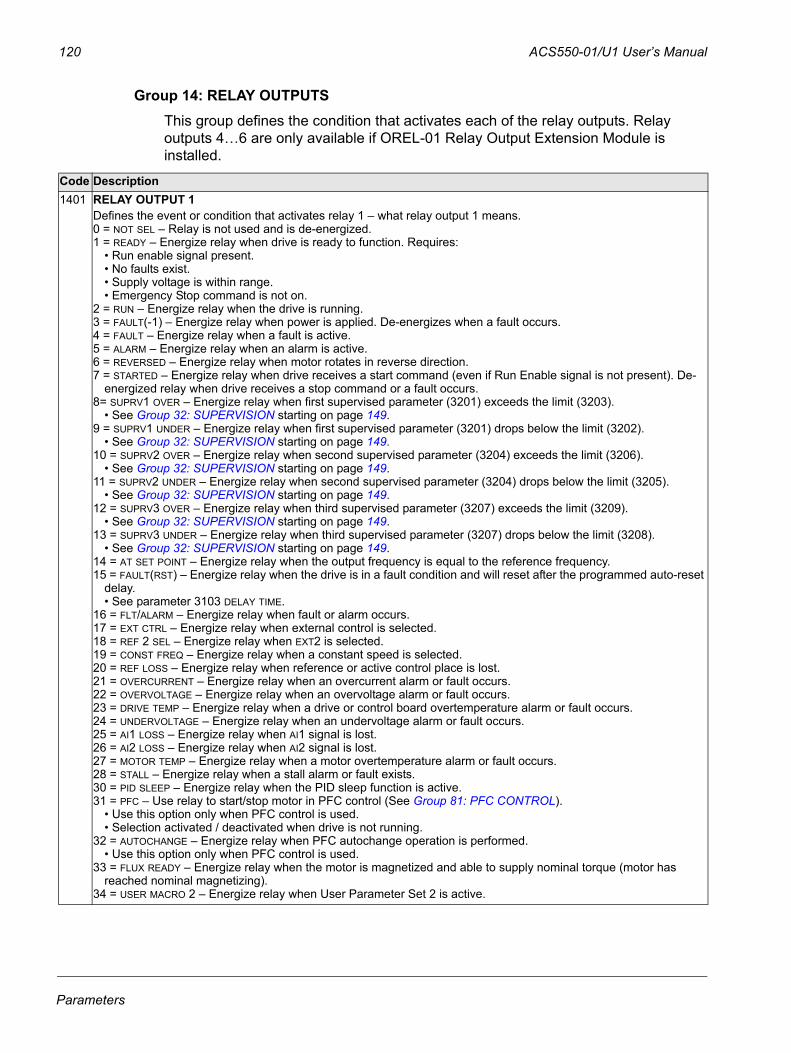
120 ACS550-01/U1 User’s Manual
Group 14: RELAY OUTPUTSThis group defines the condition that activates each of the relay outputs. Relay outputs 4…6 are only available if OREL-01 Relay Output Extension Module is installed.
Code Description1401 RELAY OUTPUT 1
Defines the event or condition that activates relay 1 – what relay output 1 means.0 = NOT SEL – Relay is not used and is de-energized.1 = READY – Energize relay when drive is ready to function. Requires:
• Run enable signal present.• No faults exist.• Supply voltage is within range. • Emergency Stop command is not on.
2 = RUN – Energize relay when the drive is running.3 = FAULT(-1) – Energize relay when power is applied. De-energizes when a fault occurs.4 = FAULT – Energize relay when a fault is active.5 = ALARM – Energize relay when an alarm is active.6 = REVERSED – Energize relay when motor rotates in reverse direction.7 = STARTED – Energize relay when drive receives a start command (even if Run Enable signal is not present). De-
energized relay when drive receives a stop command or a fault occurs.8= SUPRV1 OVER – Energize relay when first supervised parameter (3201) exceeds the limit (3203).
• See Group 32: SUPERVISION starting on page 149.9 = SUPRV1 UNDER – Energize relay when first supervised parameter (3201) drops below the limit (3202).
• See Group 32: SUPERVISION starting on page 149.10 = SUPRV2 OVER – Energize relay when second supervised parameter (3204) exceeds the limit (3206).
• See Group 32: SUPERVISION starting on page 149.11 = SUPRV2 UNDER – Energize relay when second supervised parameter (3204) drops below the limit (3205).
• See Group 32: SUPERVISION starting on page 149.12 = SUPRV3 OVER – Energize relay when third supervised parameter (3207) exceeds the limit (3209).
• See Group 32: SUPERVISION starting on page 149.13 = SUPRV3 UNDER – Energize relay when third supervised parameter (3207) drops below the limit (3208).
• See Group 32: SUPERVISION starting on page 149.14 = AT SET POINT – Energize relay when the output frequency is equal to the reference frequency.15 = FAULT(RST) – Energize relay when the drive is in a fault condition and will reset after the programmed auto-reset
delay. • See parameter 3103 DELAY TIME.
16 = FLT/ALARM – Energize relay when fault or alarm occurs.17 = EXT CTRL – Energize relay when external control is selected.18 = REF 2 SEL – Energize relay when EXT2 is selected.19 = CONST FREQ – Energize relay when a constant speed is selected.20 = REF LOSS – Energize relay when reference or active control place is lost.21 = OVERCURRENT – Energize relay when an overcurrent alarm or fault occurs.22 = OVERVOLTAGE – Energize relay when an overvoltage alarm or fault occurs.23 = DRIVE TEMP – Energize relay when a drive or control board overtemperature alarm or fault occurs.24 = UNDERVOLTAGE – Energize relay when an undervoltage alarm or fault occurs.25 = AI1 LOSS – Energize relay when AI1 signal is lost.26 = AI2 LOSS – Energize relay when AI2 signal is lost.27 = MOTOR TEMP – Energize relay when a motor overtemperature alarm or fault occurs.28 = STALL – Energize relay when a stall alarm or fault exists.30 = PID SLEEP – Energize relay when the PID sleep function is active.31 = PFC – Use relay to start/stop motor in PFC control (See Group 81: PFC CONTROL).
• Use this option only when PFC control is used.• Selection activated / deactivated when drive is not running.
32 = AUTOCHANGE – Energize relay when PFC autochange operation is performed. • Use this option only when PFC control is used.
33 = FLUX READY – Energize relay when the motor is magnetized and able to supply nominal torque (motor has reached nominal magnetizing).
34 = USER MACRO 2 – Energize relay when User Parameter Set 2 is active.
Parameters
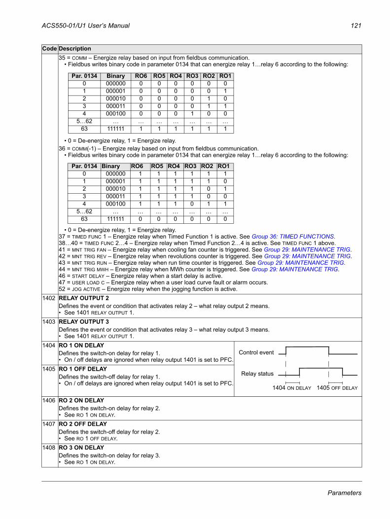
ACS550-01/U1 User’s Manual 121
35 = COMM – Energize relay based on input from fieldbus communication.• Fieldbus writes binary code in parameter 0134 that can energize relay 1…relay 6 according to the following:
• 0 = De-energize relay, 1 = Energize relay.36 = COMM(-1) – Energize relay based on input from fieldbus communication.
• Fieldbus writes binary code in parameter 0134 that can energize relay 1…relay 6 according to the following:
• 0 = De-energize relay, 1 = Energize relay.37 = TIMED FUNC 1 – Energize relay when Timed Function 1 is active. See Group 36: TIMED FUNCTIONS.38…40 = TIMED FUNC 2…4 – Energize relay when Timed Function 2…4 is active. See TIMED FUNC 1 above.41 = MNT TRIG FAN – Energize relay when cooling fan counter is triggered. See Group 29: MAINTENANCE TRIG.42 = MNT TRIG REV – Energize relay when revolutions counter is triggered. See Group 29: MAINTENANCE TRIG.43 = MNT TRIG RUN – Energize relay when run time counter is triggered. See Group 29: MAINTENANCE TRIG.44 = MNT TRIG MWH – Energize relay when MWh counter is triggered. See Group 29: MAINTENANCE TRIG.46 = START DELAY – Energize relay when a start delay is active. 47 = USER LOAD C – Energize relay when a user load curve fault or alarm occurs.52 = JOG ACTIVE – Energize relay when the jogging function is active.
1402 RELAY OUTPUT 2Defines the event or condition that activates relay 2 – what relay output 2 means.• See 1401 RELAY OUTPUT 1.
1403 RELAY OUTPUT 3Defines the event or condition that activates relay 3 – what relay output 3 means.• See 1401 RELAY OUTPUT 1.
1404 RO 1 ON DELAYDefines the switch-on delay for relay 1.• On / off delays are ignored when relay output 1401 is set to PFC.
1405 RO 1 OFF DELAYDefines the switch-off delay for relay 1. • On / off delays are ignored when relay output 1401 is set to PFC.
1406 RO 2 ON DELAYDefines the switch-on delay for relay 2. • See RO 1 ON DELAY.
1407 RO 2 OFF DELAYDefines the switch-off delay for relay 2. • See RO 1 OFF DELAY.
1408 RO 3 ON DELAYDefines the switch-on delay for relay 3.• See RO 1 ON DELAY.
Code Description
Par. 0134 Binary RO6 RO5 RO4 RO3 RO2 RO10 000000 0 0 0 0 0 01 000001 0 0 0 0 0 12 000010 0 0 0 0 1 03 000011 0 0 0 0 1 14 000100 0 0 0 1 0 0
5…62 … … … … … … …63 111111 1 1 1 1 1 1
Par. 0134 Binary RO6 RO5 RO4 RO3 RO2 RO10 000000 1 1 1 1 1 11 000001 1 1 1 1 1 02 000010 1 1 1 1 0 13 000011 1 1 1 1 0 04 000100 1 1 1 0 1 1
5…62 … … … … … … …63 111111 0 0 0 0 0 0
1404 ON DELAY 1405 OFF DELAY
Control event
Relay status
Parameters
122 ACS550-01/U1 User’s Manual
1409 RO 3 OFF DELAYSwitch-off delay for relay 3.• See RO 1 OFF DELAY.
1410…1412
RELAY OUTPUT 4…6Defines the event or condition that activates relay 4…6 – what relay output 4…6 means. Available if OREL-01 Relay Output Extension Module is installed.• See 1401 RELAY OUTPUT 1.
1413 RO 4 ON DELAYDefines the switch-on delay for relay 4. • See RO 1 ON DELAY.
1414 RO 4 OFF DELAYDefines the switch-off delay for relay 4. • See RO 1 OFF DELAY.
1415 RO 5 ON DELAYDefines the switch-on delay for relay 5. • See RO 1 ON DELAY.
1416 RO 5 OFF DELAYDefines the switch-off delay for relay 5. • See RO 1 OFF DELAY.
1417 RO 6 ON DELAYDefines the switch-on delay for relay 6.• See RO 1 ON DELAY.
1418 RO 6 OFF DELAYDefines the switch-off delay for relay 6. • See RO 1 OFF DELAY.
Code Description
Parameters
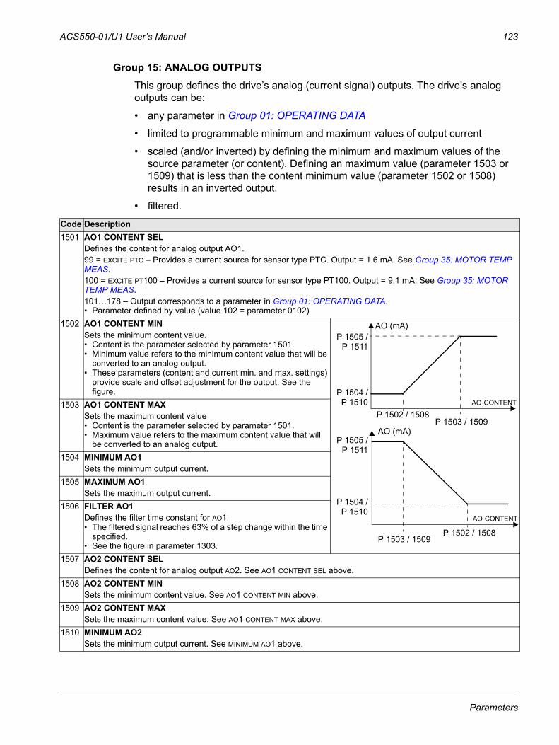
ACS550-01/U1 User’s Manual 123
Group 15: ANALOG OUTPUTSThis group defines the drive’s analog (current signal) outputs. The drive’s analog outputs can be:
• any parameter in Group 01: OPERATING DATA
• limited to programmable minimum and maximum values of output current
• scaled (and/or inverted) by defining the minimum and maximum values of the source parameter (or content). Defining an maximum value (parameter 1503 or 1509) that is less than the content minimum value (parameter 1502 or 1508) results in an inverted output.
• filtered.
Code Description1501 AO1 CONTENT SEL
Defines the content for analog output AO1. 99 = EXCITE PTC – Provides a current source for sensor type PTC. Output = 1.6 mA. See Group 35: MOTOR TEMP MEAS.100 = EXCITE PT100 – Provides a current source for sensor type PT100. Output = 9.1 mA. See Group 35: MOTOR TEMP MEAS.101…178 – Output corresponds to a parameter in Group 01: OPERATING DATA.• Parameter defined by value (value 102 = parameter 0102)
1502 AO1 CONTENT MINSets the minimum content value. • Content is the parameter selected by parameter 1501.• Minimum value refers to the minimum content value that will be
converted to an analog output.• These parameters (content and current min. and max. settings)
provide scale and offset adjustment for the output. See the figure.
1503 AO1 CONTENT MAXSets the maximum content value • Content is the parameter selected by parameter 1501.• Maximum value refers to the maximum content value that will
be converted to an analog output.1504 MINIMUM AO1
Sets the minimum output current.1505 MAXIMUM AO1
Sets the maximum output current.1506 FILTER AO1
Defines the filter time constant for AO1.• The filtered signal reaches 63% of a step change within the time
specified.• See the figure in parameter 1303.
1507 AO2 CONTENT SELDefines the content for analog output AO2. See AO1 CONTENT SEL above.
1508 AO2 CONTENT MINSets the minimum content value. See AO1 CONTENT MIN above.
1509 AO2 CONTENT MAXSets the maximum content value. See AO1 CONTENT MAX above.
1510 MINIMUM AO2Sets the minimum output current. See MINIMUM AO1 above.
AO (mA)
AO CONTENTP 1504 /
P 1502 / 1508P 1503 / 1509
AO (mA)
AO CONTENT
P 1505 /
P 1504 /
P 1503 / 1509P 1502 / 1508
P 1505 /P 1511
P 1510
P 1511
P 1510
Parameters

124 ACS550-01/U1 User’s Manual
1511 MAXIMUM AO2Sets the maximum output current. See MAXIMUM AO1 above.
1512 FILTER AO2Defines the filter time constant for AO2. See FILTER AO1 above.
Code Description
Parameters
ACS550-01/U1 User’s Manual 125
Group 16: SYSTEM CONTROLSThis group defines a variety of system level locks, resets and enables.
Code Description1601 RUN ENABLE
Selects the source of the run enable signal.0 = NOT SEL – Allows the drive to start without an external run enable signal.1 = DI1 – Defines digital input DI1 as the run enable signal.
• This digital input must be activated for run enable.• If the voltage drops and de-activates this digital input, the drive will coast to stop and not start until the run enable
signal resumes.2…6 = DI2…DI6 – Defines digital input DI2…DI6 as the run enable signal.
• See DI1 above.7 = COMM – Assigns the fieldbus Command Word as the source for the run enable signal.
• Bit 6 of the Command Word 1 (parameter 0301) activates the run disable signal.• See fieldbus user’s manual for detailed instructions.
-1 = DI1(INV) – Defines an inverted digital input DI1 as the run enable signal.• This digital input must be de-activated for run enable.• If this digital input activates, the drive will coast to stop and not start until the run enable signal resumes.
-2…-6 = DI2(INV)…DI6(INV) – Defines an inverted digital input DI2…DI6 as the run enable signal. • See DI1(INV) above.
1602 PARAMETER LOCKDetermines if the control panel can change parameter values.• This lock does not limit parameter changes made by macros.• This lock does not limit parameter changes written by fieldbus inputs.• This parameter value can be changed only if the correct pass code is entered. See parameter 1603 PASS CODE.0 = LOCKED – You cannot use the control panel to change parameter values.
• The lock can be opened by entering the valid pass code to parameter 1603. 1 = OPEN – You can use the control panel to change parameter values. 2 = NOT SAVED – You can use the control panel to change parameter values, but they are not stored in permanent
memory.• Set parameter 1607 PARAM SAVE to 1 (SAVE) to store changed parameter values to memory.
1603 PASS CODEEntering the correct pass code allows you to change the parameter lock.• See parameter 1602 above.• The code 358 allows you to change the value of the parameter 1602 once. • This entry reverts back to 0 automatically.
1604 FAULT RESET SELSelects the source for the fault reset signal. The signal resets the drive after a fault trip if the cause of the fault no longer exists.0 = KEYPAD – Defines the control panel as the only fault reset source.
• Fault reset is always possible with control panel.1 = DI1 – Defines digital input DI1 as a fault reset source.
• Activating the digital input resets the drive.2…6 = DI2…DI6 – Defines digital input DI2…DI6 as a fault reset source.
• See DI1 above.7 = START/STOP – Defines the Stop command as a fault reset source.
• Do not use this option when fieldbus communication provides the start, stop and direction commands.8 = COMM – Defines the fieldbus as a fault reset source.
• The Command Word is supplied through fieldbus communication.• The bit 4 of the Command Word 1 (parameter 0301) resets the drive.
-1 = DI1(INV) – Defines an inverted digital input DI1 as a fault reset source.• De-activating the digital input resets the drive.
-2…-6 = DI2(INV)…DI6(INV) – Defines an inverted digital input DI2…DI6 as a fault reset source.• See DI1(INV) above.
Parameters
126 ACS550-01/U1 User’s Manual
1605 USER PAR SET CHGDefines control for changing the user parameter set.• See parameter 9902 APPLIC MACRO. • The drive must be stopped to change User Parameter Sets.• During a change, the drive will not start.Note: Always save the User Parameter Set after changing any parameter settings, or performing a motor
identification. • Whenever the power is cycled, or parameter 9902 APPLIC MACRO is changed, the drive loads the last settings
saved. Any unsaved changes to a user parameter set are lost.Note: The value of this parameter (1605) is not included in the User Parameter Sets, and it does not change if User
Parameter Sets change. Note: You can use a relay output to supervise the selection of User Parameter Set 2. • See parameter 1401.0 = NOT SEL – Defines the control panel (using parameter 9902) as the only control for changing User Parameter
Sets.1 = DI1 – Defines digital input DI1 as a control for changing User Parameter Sets.
• The drive loads User Parameter Set 1 on the falling edge of the digital input.• The drive loads User Parameter Set 2 on the rising edge of the digital input.• The User Parameter Set changes only when the drive is stopped.
2…6 = DI2…DI6 – Defines digital input DI2…DI6 as a control for changing User Parameter Sets.• See DI1 above.
-1 = DI1(INV) – Defines an inverted digital input DI1 as a control for changing User Parameter Sets.• The drive loads User Parameter Set 1 on the rising edge of the digital input.• The drive loads User Parameter Set 2 on the falling edge of the digital input.• The User Parameter Set changes only when the drive is stopped.
-2…-6 = DI2(INV)…DI6(INV) – Defines an inverted digital input DI2…DI6 as a control for changing User Parameter Sets.• See DI1(INV) above.
1606 LOCAL LOCKDefines control for the use of the LOC mode. The LOC mode allows drive control from the control panel.
• When LOCAL LOCK is active, the control panel cannot change to LOC mode.0 = NOT SEL – Disables the lock. The control panel can select LOC and control the drive.1 = DI1 – Defines digital input DI1 as the control for setting the local lock.
• Activating the digital input locks out local control.• De-activating the digital input enable the LOC selection.
2…6 = DI2…DI6 – Defines digital input DI2…DI6 as the control for setting the local lock.• See DI1 above.
7 = ON – Sets the lock. The control panel cannot select LOC and cannot control the drive.8 = COMM – Defines bit 14 of the Command Word 1 as the control for setting the local lock.
• The Command Word is supplied through fieldbus communication.• The Command Word is 0301.
-1 = DI1(INV) – Defines an inverted digital input DI1 as the control for setting the local lock.• De-activating the digital input locks out local control.• Activating the digital input enable the LOC selection.
-2…-6 = DI2(INV)…DI6(INV) – Defines an inverted digital input DI2…DI6 as the control for setting the local lock.• See DI1(INV) above.
1607 PARAM SAVESaves all altered parameters to permanent memory. • Parameters altered through a fieldbus are not automatically saved to permanent memory. To save, you must use
this parameter.• If 1602 PARAMETER LOCK = 2 (NOT SAVED), parameters altered from the control panel are not saved. To save, you
must use this parameter.• If 1602 PARAMETER LOCK = 1 (OPEN), parameters altered from the control panel are stored immediately to
permanent memory. 0 = DONE – Value changes automatically when all parameters are saved.1 = SAVE… – Saves altered parameters to permanent memory.
Code Description
Parameters
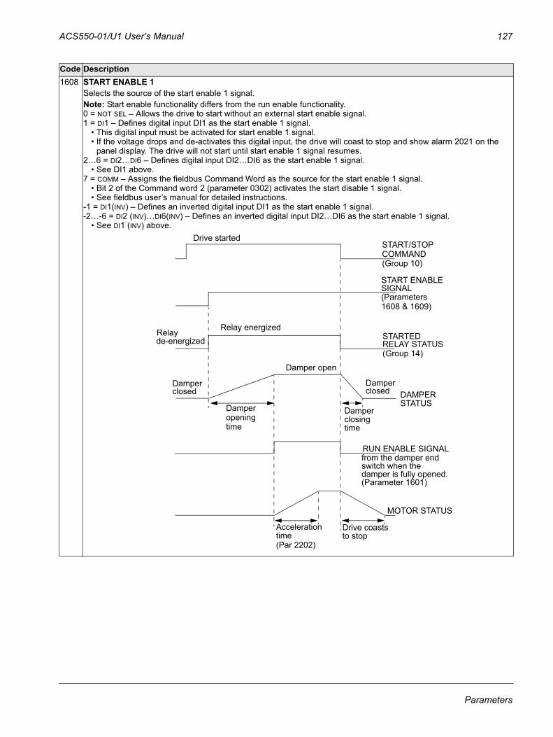
ACS550-01/U1 User’s Manual 127
1608 START ENABLE 1Selects the source of the start enable 1 signal.Note: Start enable functionality differs from the run enable functionality.0 = NOT SEL – Allows the drive to start without an external start enable signal. 1 = DI1 – Defines digital input DI1 as the start enable 1 signal.
• This digital input must be activated for start enable 1 signal.• If the voltage drops and de-activates this digital input, the drive will coast to stop and show alarm 2021 on the
panel display. The drive will not start until start enable 1 signal resumes.2…6 = DI2…DI6 – Defines digital input DI2…DI6 as the start enable 1 signal.
• See DI1 above.7 = COMM – Assigns the fieldbus Command Word as the source for the start enable 1 signal.
• Bit 2 of the Command word 2 (parameter 0302) activates the start disable 1 signal.• See fieldbus user’s manual for detailed instructions.
-1 = DI1(INV) – Defines an inverted digital input DI1 as the start enable 1 signal.-2…-6 = DI2 (INV)…DI6(INV) – Defines an inverted digital input DI2…DI6 as the start enable 1 signal.
• See DI1 (INV) above.
Code Description
Drive startedSTART/STOPCOMMAND(Group 10)
1608 & 1609)
Relay energizedRelayde-energized
Damper open
Damper
time
Damper closingtime
STARTEDRELAY STATUS(Group 14)
DAMPER STATUS
Damperclosed
RUN ENABLE SIGNALfrom the damper end switch when the damper is fully opened.(Parameter 1601)
MOTOR STATUS
Acceleration time
START ENABLE SIGNAL(Parameters
Damperclosed
opening
(Par 2202)
Drive coaststo stop
Parameters
128 ACS550-01/U1 User’s Manual
1609 START ENABLE 2 Selects the source of the start enable 2 signal.Note: Start enable functionality differs from the run enable functionality.0 = NOT SEL – Allows the drive to start without an external start enable signal. 1 = DI1 – Defines digital input DI1 as the start enable 2 signal.
• This digital input must be activated for start enable 2 signal. • If the voltage drops and de-activates this digital input, the drive will coast to stop and show alarm 2022 on the
panel display. The drive will not start until start enable 2 signal resumes.2…6 = DI2…DI6 – Defines digital input DI2…DI6 as the start enable 2 signal.
• See DI1 above.7 = COMM – Assigns the fieldbus Command Word as the source for the start enable 2 signal. Bit 3 of the Command
word 2 (parameter 0302) activates the start disable 2 signal. • See fieldbus user’s manual for detailed instructions.
-1 = DI1(INV) – Defines an inverted digital input DI1 as the start enable 2 signal.-2…-6 = DI2(INV)…DI6(INV) – Defines an inverted digital input DI2…DI6 as the start enable 2 signal.
• See DI1 (INV) above.1610 DISPLAY ALARMS
Controls the visibility of the following alarms:• 2001, Overcurrent alarm• 2002, Overvoltage alarm• 2003, Undervoltage alarm• 2009, Device overtemperature alarm.For more information, see section Alarm listing on page 261.0 = NO – The above alarms are suppressed.1 = YES – All of the above alarms are enabled.
1611 PARAMETER VIEWSelects the parameter view, i.e. which parameters are shown.Note: This parameter is visible only when it is activated by the optional FlashDrop device. FlashDrop is designed for fast copying of parameters to unpowered drives. It allows easy customization of the parameter list, e.g. selected parameters can be hidden. For more information, see MFDT-01 FlashDrop User’s Manual (3AFE68591074 [English]).FlashDrop parameter values are activated by setting parameter 9902 to 31 (LOAD FD SET).0 = DEFAULT – Complete long and short parameter lists are shown.1 = FLASHDROP – FlashDrop parameter list is shown. Does not include short parameter list. Parameters that are
hidden by the FlashDrop device are not visible.
Code Description
Parameters
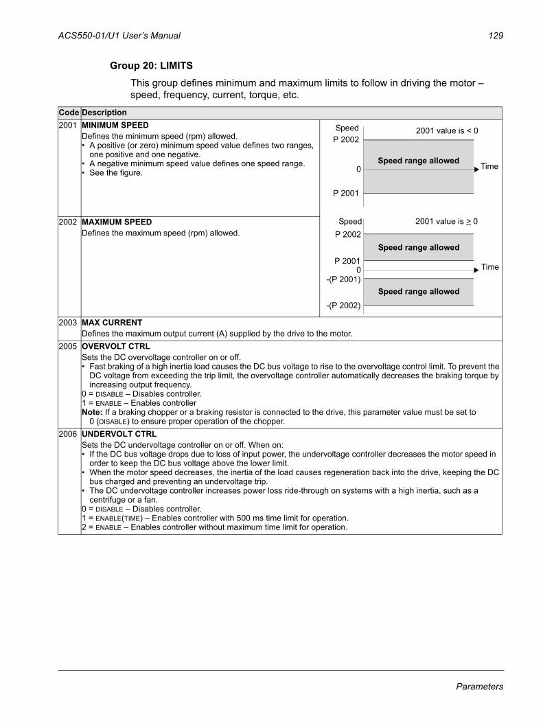
ACS550-01/U1 User’s Manual 129
Group 20: LIMITSThis group defines minimum and maximum limits to follow in driving the motor – speed, frequency, current, torque, etc.
Code Description2001 MINIMUM SPEED
Defines the minimum speed (rpm) allowed. • A positive (or zero) minimum speed value defines two ranges,
one positive and one negative.• A negative minimum speed value defines one speed range.• See the figure.
2002 MAXIMUM SPEEDDefines the maximum speed (rpm) allowed.
2003 MAX CURRENTDefines the maximum output current (A) supplied by the drive to the motor.
2005 OVERVOLT CTRLSets the DC overvoltage controller on or off.• Fast braking of a high inertia load causes the DC bus voltage to rise to the overvoltage control limit. To prevent the
DC voltage from exceeding the trip limit, the overvoltage controller automatically decreases the braking torque by increasing output frequency.
0 = DISABLE – Disables controller.1 = ENABLE – Enables controllerNote: If a braking chopper or a braking resistor is connected to the drive, this parameter value must be set to
0 (DISABLE) to ensure proper operation of the chopper.2006 UNDERVOLT CTRL
Sets the DC undervoltage controller on or off. When on:• If the DC bus voltage drops due to loss of input power, the undervoltage controller decreases the motor speed in
order to keep the DC bus voltage above the lower limit. • When the motor speed decreases, the inertia of the load causes regeneration back into the drive, keeping the DC
bus charged and preventing an undervoltage trip. • The DC undervoltage controller increases power loss ride-through on systems with a high inertia, such as a
centrifuge or a fan.0 = DISABLE – Disables controller.1 = ENABLE(TIME) – Enables controller with 500 ms time limit for operation.2 = ENABLE – Enables controller without maximum time limit for operation.
P 2001
P 2002Speed
-(P 2001)
-(P 2002)
P 2002
P 2001
Speed range allowed
Speed range allowed
Speed range allowed
Time
Speed
Time
2001 value is > 0
0
0
2001 value is < 0
Parameters
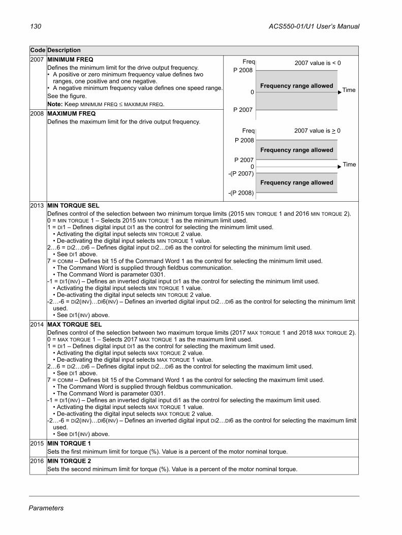
130 ACS550-01/U1 User’s Manual
2007 MINIMUM FREQDefines the minimum limit for the drive output frequency.• A positive or zero minimum frequency value defines two
ranges, one positive and one negative.• A negative minimum frequency value defines one speed range.See the figure.Note: Keep MINIMUM FREQ ≤ MAXIMUM FREQ.
2008 MAXIMUM FREQDefines the maximum limit for the drive output frequency.
2013 MIN TORQUE SELDefines control of the selection between two minimum torque limits (2015 MIN TORQUE 1 and 2016 MIN TORQUE 2).0 = MIN TORQUE 1 – Selects 2015 MIN TORQUE 1 as the minimum limit used.1 = DI1 – Defines digital input DI1 as the control for selecting the minimum limit used.
• Activating the digital input selects MIN TORQUE 2 value.• De-activating the digital input selects MIN TORQUE 1 value.
2…6 = DI2…DI6 – Defines digital input DI2…DI6 as the control for selecting the minimum limit used.• See DI1 above.
7 = COMM – Defines bit 15 of the Command Word 1 as the control for selecting the minimum limit used.• The Command Word is supplied through fieldbus communication.• The Command Word is parameter 0301.
-1 = DI1(INV) – Defines an inverted digital input DI1 as the control for selecting the minimum limit used.• Activating the digital input selects MIN TORQUE 1 value.• De-activating the digital input selects MIN TORQUE 2 value.
-2…-6 = DI2(INV)…DI6(INV) – Defines an inverted digital input DI2…DI6 as the control for selecting the minimum limit used.• See DI1(INV) above.
2014 MAX TORQUE SELDefines control of the selection between two maximum torque limits (2017 MAX TORQUE 1 and 2018 MAX TORQUE 2).0 = MAX TORQUE 1 – Selects 2017 MAX TORQUE 1 as the maximum limit used.1 = DI1 – Defines digital input DI1 as the control for selecting the maximum limit used.
• Activating the digital input selects MAX TORQUE 2 value.• De-activating the digital input selects MAX TORQUE 1 value.
2…6 = DI2…DI6 – Defines digital input DI2…DI6 as the control for selecting the maximum limit used.• See DI1 above.
7 = COMM – Defines bit 15 of the Command Word 1 as the control for selecting the maximum limit used.• The Command Word is supplied through fieldbus communication.• The Command Word is parameter 0301.
-1 = DI1(INV) – Defines an inverted digital input di1 as the control for selecting the maximum limit used.• Activating the digital input selects MAX TORQUE 1 value.• De-activating the digital input selects MAX TORQUE 2 value.
-2…-6 = DI2(INV)…DI6(INV) – Defines an inverted digital input DI2…DI6 as the control for selecting the maximum limit used.• See DI1(INV) above.
2015 MIN TORQUE 1Sets the first minimum limit for torque (%). Value is a percent of the motor nominal torque.
2016 MIN TORQUE 2Sets the second minimum limit for torque (%). Value is a percent of the motor nominal torque.
Code Description
P 2007
P 2008Freq
-(P 2007)
-(P 2008)
P 2008
P 2007
Frequency range allowed
Frequency range allowed
Frequency range allowed
Time
Freq
Time
2007 value is > 0
0
0
2007 value is < 0
Parameters

ACS550-01/U1 User’s Manual 131
2017 MAX TORQUE 1Sets the first maximum limit for torque (%). Value is a percent of the motor nominal torque.
2018 MAX TORQUE 2Sets the second maximum limit for torque (%). Value is a percent of the motor nominal torque.
Code Description
Parameters
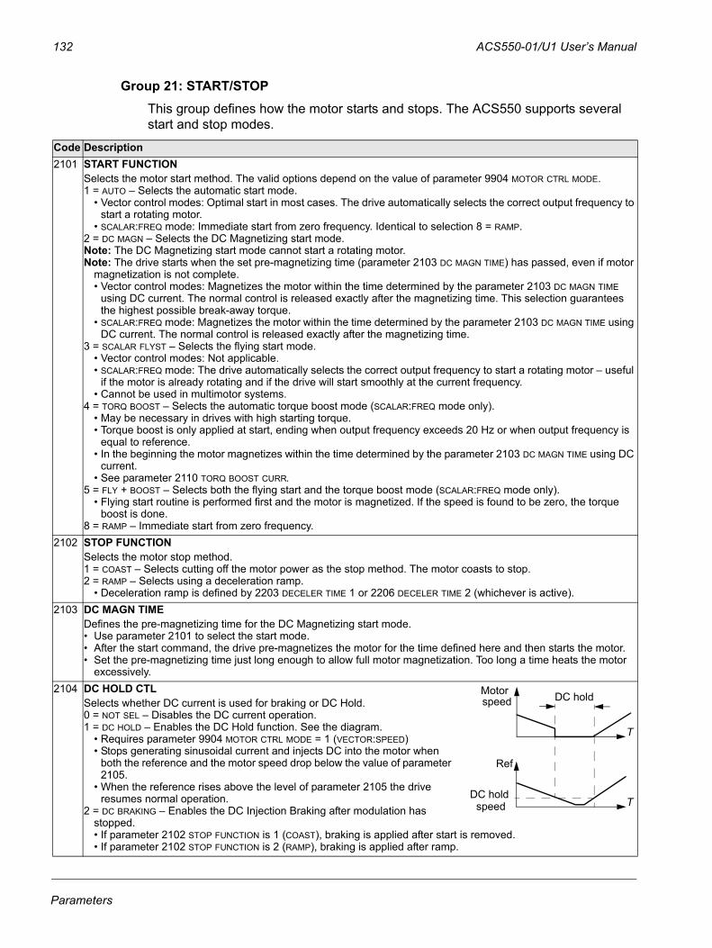
132 ACS550-01/U1 User’s Manual
Group 21: START/STOPThis group defines how the motor starts and stops. The ACS550 supports several start and stop modes.
Code Description2101 START FUNCTION
Selects the motor start method. The valid options depend on the value of parameter 9904 MOTOR CTRL MODE.1 = AUTO – Selects the automatic start mode.
• Vector control modes: Optimal start in most cases. The drive automatically selects the correct output frequency to start a rotating motor.
• SCALAR:FREQ mode: Immediate start from zero frequency. Identical to selection 8 = RAMP.2 = DC MAGN – Selects the DC Magnetizing start mode.Note: The DC Magnetizing start mode cannot start a rotating motor.Note: The drive starts when the set pre-magnetizing time (parameter 2103 DC MAGN TIME) has passed, even if motor
magnetization is not complete. • Vector control modes: Magnetizes the motor within the time determined by the parameter 2103 DC MAGN TIME
using DC current. The normal control is released exactly after the magnetizing time. This selection guarantees the highest possible break-away torque.
• SCALAR:FREQ mode: Magnetizes the motor within the time determined by the parameter 2103 DC MAGN TIME using DC current. The normal control is released exactly after the magnetizing time.
3 = SCALAR FLYST – Selects the flying start mode.• Vector control modes: Not applicable.• SCALAR:FREQ mode: The drive automatically selects the correct output frequency to start a rotating motor – useful
if the motor is already rotating and if the drive will start smoothly at the current frequency.• Cannot be used in multimotor systems.
4 = TORQ BOOST – Selects the automatic torque boost mode (SCALAR:FREQ mode only).• May be necessary in drives with high starting torque. • Torque boost is only applied at start, ending when output frequency exceeds 20 Hz or when output frequency is
equal to reference. • In the beginning the motor magnetizes within the time determined by the parameter 2103 DC MAGN TIME using DC
current.• See parameter 2110 TORQ BOOST CURR.
5 = FLY + BOOST – Selects both the flying start and the torque boost mode (SCALAR:FREQ mode only).• Flying start routine is performed first and the motor is magnetized. If the speed is found to be zero, the torque
boost is done.8 = RAMP – Immediate start from zero frequency.
2102 STOP FUNCTIONSelects the motor stop method.1 = COAST – Selects cutting off the motor power as the stop method. The motor coasts to stop.2 = RAMP – Selects using a deceleration ramp.
• Deceleration ramp is defined by 2203 DECELER TIME 1 or 2206 DECELER TIME 2 (whichever is active).2103 DC MAGN TIME
Defines the pre-magnetizing time for the DC Magnetizing start mode.• Use parameter 2101 to select the start mode.• After the start command, the drive pre-magnetizes the motor for the time defined here and then starts the motor.• Set the pre-magnetizing time just long enough to allow full motor magnetization. Too long a time heats the motor
excessively.2104 DC HOLD CTL
Selects whether DC current is used for braking or DC Hold. 0 = NOT SEL – Disables the DC current operation. 1 = DC HOLD – Enables the DC Hold function. See the diagram.
• Requires parameter 9904 MOTOR CTRL MODE = 1 (VECTOR:SPEED)• Stops generating sinusoidal current and injects DC into the motor when
both the reference and the motor speed drop below the value of parameter 2105.
• When the reference rises above the level of parameter 2105 the drive resumes normal operation.
2 = DC BRAKING – Enables the DC Injection Braking after modulation has stopped.• If parameter 2102 STOP FUNCTION is 1 (COAST), braking is applied after start is removed. • If parameter 2102 STOP FUNCTION is 2 (RAMP), braking is applied after ramp.
speed
Ref
DC hold
DC hold
Motor
speed T
T
Parameters
ACS550-01/U1 User’s Manual 133
2105 DC HOLD SPEEDSets the speed for DC Hold. Requires that parameter 2104 DC HOLD CTL = 1 (DC HOLD).
2106 DC CURR REFDefines the DC current control reference as a percentage of parameter 9906 MOTOR NOM CURR.
2107 DC BRAKE TIMEDefines the DC brake time after modulation has stopped, if parameter 2104 is 2 (DC BRAKING).
2108 START INHIBITSets the Start inhibit function on or off. If the drive is not actively started and running, the Start inhibit function ignores a pending start command in any of the following situations and a new start command is required:• A fault is reset.• Run Enable (parameter 1601) activates while start command is active.• Mode changes from local to remote.• Control switches from EXT1 to EXT2.• Control switches from EXT2 to EXT1.0 = OFF – Disables the Start inhibit function. 1 = ON – Enables the Start inhibit function.
2109 EMERG STOP SELDefines control of the Emergency stop command. When activated:• Emergency stop decelerates the motor using the emergency stop ramp (parameter 2208 EMERG DEC TIME).• Requires an external stop command and removal of the emergency stop command before drive can restart.0 = NOT SEL – Disables the Emergency stop function through digital inputs.1 = DI1 – Defines digital input DI1 as the control for Emergency stop command.
• Activating the digital input issues an Emergency stop command.• De-activating the digital input removes the Emergency stop command.
2…6 = DI2…DI6 – Defines digital input DI2…DI6 as the control for Emergency stop command. • See DI1 above.
-1 = DI1(INV) – Defines an inverted digital input DI1 as the control for Emergency stop command. • De-activating the digital input issues an Emergency stop command.• Activating the digital input removes the Emergency stop command.
-2…-6 = DI2(INV)…DI6(INV) – Defines an inverted digital input DI2…DI6 as the control for Emergency stop command.• See DI1(INV) above.
2110 TORQ BOOST CURRSets the maximum supplied current during torque boost. • See parameter 2101 START FUNCTION.
Code Description
Parameters
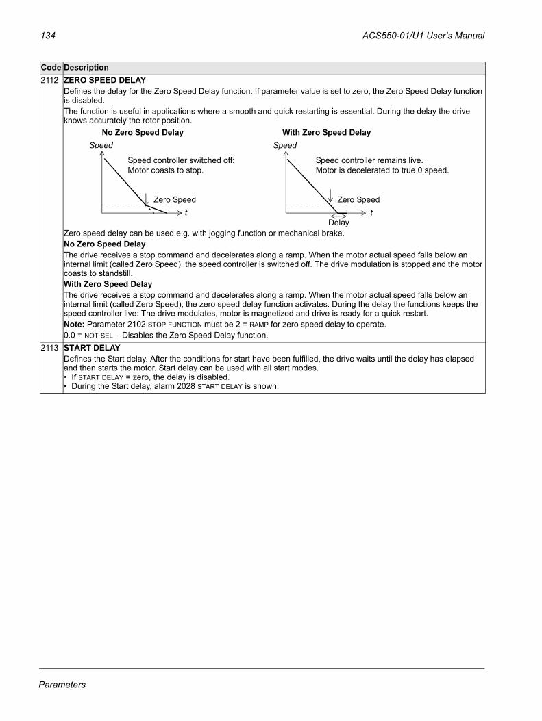
134 ACS550-01/U1 User’s Manual
2112 ZERO SPEED DELAYDefines the delay for the Zero Speed Delay function. If parameter value is set to zero, the Zero Speed Delay function is disabled.The function is useful in applications where a smooth and quick restarting is essential. During the delay the drive knows accurately the rotor position.
Zero speed delay can be used e.g. with jogging function or mechanical brake.No Zero Speed DelayThe drive receives a stop command and decelerates along a ramp. When the motor actual speed falls below an internal limit (called Zero Speed), the speed controller is switched off. The drive modulation is stopped and the motor coasts to standstill.With Zero Speed DelayThe drive receives a stop command and decelerates along a ramp. When the motor actual speed falls below an internal limit (called Zero Speed), the zero speed delay function activates. During the delay the functions keeps the speed controller live: The drive modulates, motor is magnetized and drive is ready for a quick restart.Note: Parameter 2102 STOP FUNCTION must be 2 = RAMP for zero speed delay to operate.0.0 = NOT SEL – Disables the Zero Speed Delay function.
2113 START DELAYDefines the Start delay. After the conditions for start have been fulfilled, the drive waits until the delay has elapsed and then starts the motor. Start delay can be used with all start modes.• If START DELAY = zero, the delay is disabled.• During the Start delay, alarm 2028 START DELAY is shown.
Code Description
Speed
tZero Speed
Speed
tZero Speed
Delay
No Zero Speed Delay With Zero Speed Delay
Speed controller switched off: Motor coasts to stop.
Speed controller remains live. Motor is decelerated to true 0 speed.
Parameters
ACS550-01/U1 User’s Manual 135
Group 22: ACCEL/DECELThis group defines ramps that control the rate of acceleration and deceleration. You define these ramps as a pair, one for acceleration and one for deceleration. You can define two pairs of ramps and use a digital input to select one or the other pair.
Code Description2201 ACC/DEC 1/2 SEL
Defines control for selection of acceleration/deceleration ramps.• Ramps are defined in pairs, one each for acceleration and deceleration.• See below for the ramp definition parameters.0 = NOT SEL – Disables selection, the first ramp pair is used.1 = DI1 – Defines digital input DI1 as the control for ramp pair selection.
• Activating the digital input selects ramp pair 2.• De-activating the digital input selects ramp pair 1.
2…6 = DI2…DI6 – Defines digital input DI2…DI6 as the control for ramp pair selection. • See DI1 above.
7 = COMM – Defines bit 10 of the Command Word 1 as the control for ramp pair selection.• The Command Word is supplied through fieldbus communication.• The Command Word is parameter 0301.
-1 = DI1(INV) – Defines an inverted digital input DI1 as the control for ramp pair selection. • De-activating the digital input selects ramp pair 2• Activating the digital input selects ramp pair 1.
-2…-6 = DI2(INV)…DI6(INV) – Defines an inverted digital input DI2…DI6 as the control for ramp pair selection. • See DI1(INV) above.
2202 ACCELER TIME 1Sets the acceleration time for zero to maximum frequency for ramp pair 1. See A in the figure.• Actual acceleration time also depends on 2204 RAMP SHAPE 1.• See 2008 MAXIMUM FREQ.
2203 DECELER TIME 1Sets the deceleration time for maximum frequency to zero for ramp pair 1. • Actual deceleration time also depends on 2204 RAMP SHAPE 1.• See 2008 MAXIMUM FREQ.
2204 RAMP SHAPE 1Selects the shape of the acceleration/deceleration ramp for ramp pair 1. See B in the figure.• Shape is defined as a ramp, unless additional time is specified here to reach the
maximum frequency. A longer time provides a softer transition at each end of the slope. The shape becomes an s-curve.
• Rule of thumb: 1/5 is a suitable relation between the ramp shape time and the acceleration ramp time.
0.0 = LINEAR – Specifies linear acceleration/deceleration ramps for ramp pair 1.0.1…1000.0 = S-CURVE – Specifies s-curve acceleration/deceleration ramps for
ramp pair 1. 2205 ACCELER TIME 2
Sets the acceleration time for zero to maximum frequency for ramp pair 2. • See 2202 ACCELER TIME 1.• Used also as jogging acceleration time. See 1004 JOGGING SEL.
2206 DECELER TIME 2Sets the deceleration time for maximum frequency to zero for ramp pair 2. • See 2203 DECELER TIME 1.• Used also as jogging deceleration time. See 1004 JOGGING SEL.
2207 RAMP SHAPE 2Selects the shape of the acceleration/deceleration ramp for ramp pair 2.• See 2204 RAMP SHAPE 1.
FREQ
MAXFREQ
Linear
S-curve
AA = 2202 ACCELER TIME 1
B
B (=0)
B = 2204 RAMP SHAPE 1
MAX
T
T
Parameters
136 ACS550-01/U1 User’s Manual
2208 EMERG DEC TIMESets the deceleration time for maximum frequency to zero for an emergency. • See parameter 2109 EMERG STOP SEL.• Ramp is linear.
2209 RAMP INPUT 0Defines control for forcing the speed to 0 with the currently used deceleration ramp (see parameters 2203 DECELER TIME 1 and 2206 DECELER TIME 2). 0 = NOT SEL – Not selected.1 = DI1 – Defines digital input DI1 as the control for forcing the speed to 0.
• Activating the digital input forces the speed to zero, after which the speed will stay at 0.• De-activating the digital input: speed control resumes normal operation.
2…6 = DI2…DI6 – Defines digital input DI2…DI6 as the control for forcing the speed to 0.• See DI1 above.
7 = COMM – Defines bit 13 of the Command Word 1 as the control for forcing the speed to 0.• The Command Word is supplied through fieldbus communication.• The Command Word is parameter 0301.
-1 = DI1(INV) – Defines inverted digital input DI1 as the control for forcing the speed to 0. • De-activating the digital input forces the speed to 0.• Activating the digital input: speed control resumes normal operation.
-2…-6 = DI2(INV)…DI6(INV) – Defines an inverted digital input DI2…DI6 as the control for forcing the speed to 0. • See DI1(INV) above.
Code Description
Parameters
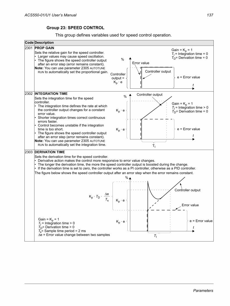
ACS550-01/U1 User’s Manual 137
Group 23: SPEED CONTROLThis group defines variables used for speed control operation.
Code Description2301 PROP GAIN
Sets the relative gain for the speed controller. • Larger values may cause speed oscillation. • The figure shows the speed controller output
after an error step (error remains constant). Note: You can use parameter 2305 AUTOTUNE
RUN to automatically set the proportional gain.
2302 INTEGRATION TIMESets the integration time for the speed controller. • The integration time defines the rate at which
the controller output changes for a constant error value.
• Shorter integration times correct continuous errors faster.
• Control becomes unstable if the integration time is too short.
• The figure shows the speed controller output after an error step (error remains constant).
Note: You can use parameter 2305 AUTOTUNE RUN to automatically set the integration time.
2303 DERIVATION TIMESets the derivation time for the speed controller. • Derivative action makes the control more responsive to error value changes. • The longer the derivation time, the more the speed controller output is boosted during the change. • If the derivation time is set to zero, the controller works as a PI controller, otherwise as a PID controller. The figure below shows the speed controller output after an error step when the error remains constant.
Gain = Kp = 1TI = Integration time = 0TD= Derivation time = 0
Error value
Controller output
%
e = Error value
t
Controlleroutput =
Kp · e
TI
Controller output%
Gain = Kp = 1TI = Integration time > 0TD= Derivation time = 0Kp · e
e = Error valueKp · e
t
Gain = Kp = 1TI = Integration time > 0TD= Derivation time > 0Ts= Sample time period = 2 msΔe = Error value change between two samples TI
Kp · e
Error value
Controller output
%
e = Error value
Kp · TD ·ΔeTs Kp · e
t
Parameters
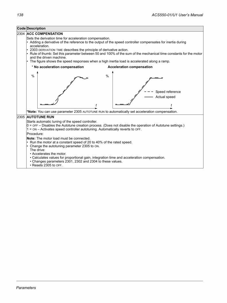
138 ACS550-01/U1 User’s Manual
2304 ACC COMPENSATIONSets the derivation time for acceleration compensation. • Adding a derivative of the reference to the output of the speed controller compensates for inertia during
acceleration. • 2303 DERIVATION TIME describes the principle of derivative action.• Rule of thumb: Set this parameter between 50 and 100% of the sum of the mechanical time constants for the motor
and the driven machine. • The figure shows the speed responses when a high inertia load is accelerated along a ramp.
*Note: You can use parameter 2305 AUTOTUNE RUN to automatically set acceleration compensation.2305 AUTOTUNE RUN
Starts automatic tuning of the speed controller.0 = OFF – Disables the Autotune creation process. (Does not disable the operation of Autotune settings.)1 = ON – Activates speed controller autotuning. Automatically reverts to OFF.Procedure:Note: The motor load must be connected.• Run the motor at a constant speed of 20 to 40% of the rated speed.• Change the autotuning parameter 2305 to ON.
The drive:• Accelerates the motor.• Calculates values for proportional gain, integration time and acceleration compensation.• Changes parameters 2301, 2302 and 2304 to these values.• Resets 2305 to OFF.
Code Description
Speed referenceActual speed
* No acceleration compensation Acceleration compensation
% %
tt
Parameters
ACS550-01/U1 User’s Manual 139
Group 24: TORQUE CONTROLThis group defines variables used for torque control operation.
Code Description2401 TORQ RAMP UP
Defines the torque reference ramp up time – The minimum time for the reference to increase from zero to the nominal motor torque.
2402 TORQ RAMP DOWNDefines the torque reference ramp down time – The minimum time for the reference to decrease from the nominal motor torque to zero.
Parameters
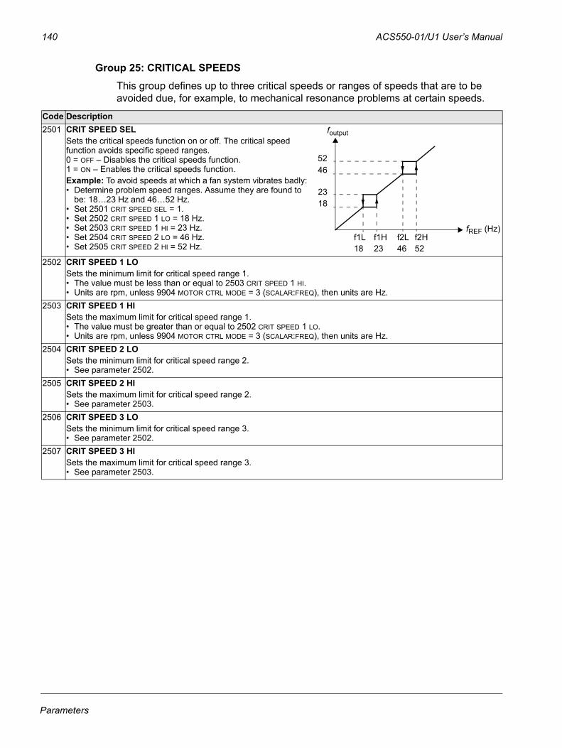
140 ACS550-01/U1 User’s Manual
Group 25: CRITICAL SPEEDSThis group defines up to three critical speeds or ranges of speeds that are to be avoided due, for example, to mechanical resonance problems at certain speeds.
Code Description2501 CRIT SPEED SEL
Sets the critical speeds function on or off. The critical speed function avoids specific speed ranges.0 = OFF – Disables the critical speeds function.1 = ON – Enables the critical speeds function.Example: To avoid speeds at which a fan system vibrates badly:• Determine problem speed ranges. Assume they are found to
be: 18…23 Hz and 46…52 Hz. • Set 2501 CRIT SPEED SEL = 1.• Set 2502 CRIT SPEED 1 LO = 18 Hz.• Set 2503 CRIT SPEED 1 HI = 23 Hz.• Set 2504 CRIT SPEED 2 LO = 46 Hz.• Set 2505 CRIT SPEED 2 HI = 52 Hz.
2502 CRIT SPEED 1 LOSets the minimum limit for critical speed range 1.• The value must be less than or equal to 2503 CRIT SPEED 1 HI.• Units are rpm, unless 9904 MOTOR CTRL MODE = 3 (SCALAR:FREQ), then units are Hz.
2503 CRIT SPEED 1 HISets the maximum limit for critical speed range 1.• The value must be greater than or equal to 2502 CRIT SPEED 1 LO.• Units are rpm, unless 9904 MOTOR CTRL MODE = 3 (SCALAR:FREQ), then units are Hz.
2504 CRIT SPEED 2 LOSets the minimum limit for critical speed range 2.• See parameter 2502.
2505 CRIT SPEED 2 HISets the maximum limit for critical speed range 2.• See parameter 2503.
2506 CRIT SPEED 3 LOSets the minimum limit for critical speed range 3.• See parameter 2502.
2507 CRIT SPEED 3 HISets the maximum limit for critical speed range 3.• See parameter 2503.
5246
2318
f1L18
f2L46
f1H23
f2H52
foutput
fREF (Hz)
Parameters
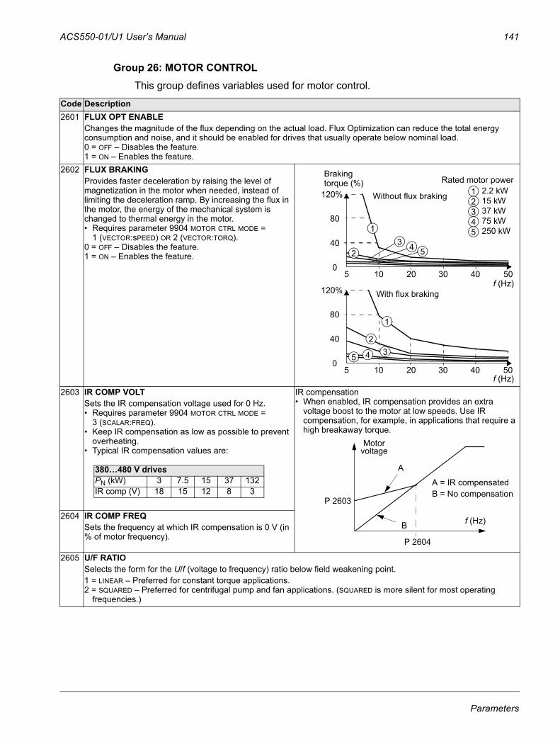
ACS550-01/U1 User’s Manual 141
Group 26: MOTOR CONTROLThis group defines variables used for motor control.
Code Description2601 FLUX OPT ENABLE
Changes the magnitude of the flux depending on the actual load. Flux Optimization can reduce the total energy consumption and noise, and it should be enabled for drives that usually operate below nominal load.0 = OFF – Disables the feature. 1 = ON – Enables the feature.
2602 FLUX BRAKINGProvides faster deceleration by raising the level of magnetization in the motor when needed, instead of limiting the deceleration ramp. By increasing the flux in the motor, the energy of the mechanical system is changed to thermal energy in the motor. • Requires parameter 9904 MOTOR CTRL MODE =
1 (VECTOR:sPEED) OR 2 (VECTOR:TORQ).0 = OFF – Disables the feature.1 = ON – Enables the feature.
2603 IR COMP VOLTSets the IR compensation voltage used for 0 Hz.• Requires parameter 9904 MOTOR CTRL MODE =
3 (SCALAR:FREQ).• Keep IR compensation as low as possible to prevent
overheating.• Typical IR compensation values are:
IR compensation• When enabled, IR compensation provides an extra
voltage boost to the motor at low speeds. Use IR compensation, for example, in applications that require a high breakaway torque.
2604 IR COMP FREQSets the frequency at which IR compensation is 0 V (in % of motor frequency).
2605 U/F RATIOSelects the form for the U/f (voltage to frequency) ratio below field weakening point. 1 = LINEAR – Preferred for constant torque applications.2 = SQUARED – Preferred for centrifugal pump and fan applications. (SQUARED is more silent for most operating
frequencies.)
120%
80
40
0
Without flux braking
50
With flux braking
5 10 20 30 40
120%
80
40
0505 10 20 30 40
1
234
5
1
23
45
1
23
4
5
2.2 kW15 kW37 kW75 kW250 kW
Rated motor powerBraking torque (%)
f (Hz)
f (Hz)
380…480 V drivesPN (kW) 3 7.5 15 37 132IR comp (V) 18 15 12 8 3
Motor
A
B
voltage
A = IR compensated B = No compensation
P 2603
P 2604
f (Hz)
Parameters
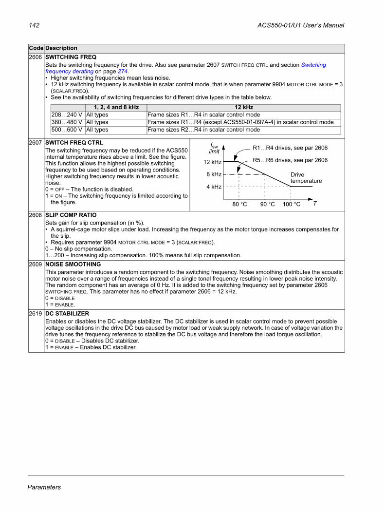
142 ACS550-01/U1 User’s Manual
2606 SWITCHING FREQSets the switching frequency for the drive. Also see parameter 2607 SWITCH FREQ CTRL and section Switching frequency derating on page 274.• Higher switching frequencies mean less noise. • 12 kHz switching frequency is available in scalar control mode, that is when parameter 9904 MOTOR CTRL MODE = 3
(SCALAR:FREQ). • See the availability of switching frequencies for different drive types in the table below.
2607 SWITCH FREQ CTRLThe switching frequency may be reduced if the ACS550 internal temperature rises above a limit. See the figure. This function allows the highest possible switching frequency to be used based on operating conditions. Higher switching frequency results in lower acoustic noise.0 = OFF – The function is disabled.1 = ON – The switching frequency is limited according to
the figure.
2608 SLIP COMP RATIOSets gain for slip compensation (in %).• A squirrel-cage motor slips under load. Increasing the frequency as the motor torque increases compensates for
the slip. • Requires parameter 9904 MOTOR CTRL MODE = 3 (SCALAR:FREQ).0 – No slip compensation. 1…200 – Increasing slip compensation. 100% means full slip compensation.
2609 NOISE SMOOTHINGThis parameter introduces a random component to the switching frequency. Noise smoothing distributes the acoustic motor noise over a range of frequencies instead of a single tonal frequency resulting in lower peak noise intensity. The random component has an average of 0 Hz. It is added to the switching frequency set by parameter 2606 SWITCHING FREQ. This parameter has no effect if parameter 2606 = 12 kHz.0 = DISABLE1 = ENABLE.
2619 DC STABILIZEREnables or disables the DC voltage stabilizer. The DC stabilizer is used in scalar control mode to prevent possible voltage oscillations in the drive DC bus caused by motor load or weak supply network. In case of voltage variation the drive tunes the frequency reference to stabilize the DC bus voltage and therefore the load torque oscillation.0 = DISABLE – Disables DC stabilizer.1 = ENABLE – Enables DC stabilizer.
Code Description
1, 2, 4 and 8 kHz 12 kHz208…240 V All types Frame sizes R1…R4 in scalar control mode380…480 V All types Frame sizes R1…R4 (except ACS550-01-097A-4) in scalar control mode500…600 V All types Frame sizes R2…R4 in scalar control mode
80 °C 100 °C
4 kHz
12 kHz
8 kHz
90 °C
fswlimit
T
R1…R4 drives, see par 2606
R5…R6 drives, see par 2606
Drivetemperature
Parameters
ACS550-01/U1 User’s Manual 143
Group 29: MAINTENANCE TRIGThis group contains usage levels and trigger points. When usage reaches the set trigger point, a notice displayed on the control panel signals that maintenance is due.
Code Description2901 COOLING FAN TRIG
Sets the trigger point for the drive’s cooling fan counter. • Value is compared to parameter 2902 value.0.0 – Disables the trigger.
2902 COOLING FAN ACTDefines the actual value of the drive’s cooling fan counter. • When parameter 2901 has been set to a non-zero value, the counter starts. • When the actual value of the counter exceeds the value defined by parameter 2901, a maintenance notice is
displayed on the panel.0.0 – Resets the parameter.
2903 REVOLUTION TRIGSets the trigger point for the motor’s accumulated revolutions counter. • Value is compared to parameter 2904 value.0 – Disables the trigger.
2904 REVOLUTION ACTDefines the actual value of the motor’s accumulated revolutions counter. • When parameter 2903 has been set to a non-zero value, the counter starts. • When the actual value of the counter exceeds the value defined by parameter 2903, a maintenance notice is
displayed on the panel.0 – Resets the parameter.
2905 RUN TIME TRIGSets the trigger point for the drive’s run time counter. • Value is compared to parameter 2906 value.0.0 – Disables the trigger.
2906 RUN TIME ACTDefines the actual value of the drive’s run time counter. • When parameter 2905 has been set to a non-zero value, the counter starts. • When the actual value of the counter exceeds the value defined by parameter 2905, a maintenance notice is
displayed on the panel.0.0 – Resets the parameter.
2907 USER MWh TRIGSets the trigger point for the drive’s accumulated power consumption (in megawatt hours) counter. • Value is compared to parameter 2908 value.0.0 – Disables the trigger.
2908 USER MWh ACTDefines the actual value of the drive’s accumulated power consumption (in megawatt hours) counter. • When parameter 2907 has been set to a non-zero value, the counter starts. • When the actual value of the counter exceeds the value defined by parameter 2907, a maintenance notice is
displayed on the panel.0.0 – Resets the parameter.
Parameters
144 ACS550-01/U1 User’s Manual
Group 30: FAULT FUNCTIONSThis group defines situations that the drive should recognize as potential faults and defines how the drive should respond if the fault is detected.
Code Description3001 AI<MIN FUNCTION
Defines the drive response if the analog input (AI) signal drops below the fault limits and AI is used • as the active reference source (Group 11: REFERENCE SELECT)• as the Process or External PID controllers' feedback or setpoint source (Group 40: PROCESS PID SET 1, Group
41: PROCESS PID SET 2 or Group 42: EXT / TRIM PID) and the corresponding PID controller is active.3021 AI1 FAULT LIMIT and 3022 AI2 FAULT LIMIT set the fault limits.0 = NOT SEL – No response.1 = FAULT – Displays a fault (7, AI1 LOSS or 8, AI2 LOSS) and the drive coasts to stop.2 = CONST SP 7 – Displays an alarm (2006, AI1 LOSS or 2007, AI2 LOSS) and sets speed using 1208 CONST SPEED 7.3 = LAST SPEED – Displays an alarm (2006, AI1 LOSS or 2007, AI2 LOSS) and sets speed using the last operating level.
This value is the average speed over the last 10 seconds.WARNING! If you select CONST SP 7 or LAST SPEED, make sure that continued operation is safe when the analog input signal is lost.
3002 PANEL COMM ERRDefines the drive response to a control panel communication error.1 = FAULT – Displays a fault (10, PANEL LOSS) and the drive coasts to stop.2 = CONST SP 7 – Displays an alarm (2008, PANEL LOSS) and sets speed using 1208 CONST SPEED 7.3 = LAST SPEED – Displays an alarm (2008, PANEL LOSS) and sets speed using the last operating level. This value is
the average speed over the last 10 seconds.Note: When either of the two external control locations are active, and start, stop and/or direction are through the
control panel – 1001 EXT1 COMMANDS / 1002 EXT2 COMMANDS = 8 (KEYPAD) – the drive follows speed/frequency reference according to the configuration of the external control locations, instead of the value of the last speed or parameter 1208 CONST SPEED 7.
WARNING! If you select CONST SP 7 or LAST SPEED, make sure that continued operation is safe when the control panel communication is lost.
3003 EXTERNAL FAULT 1Defines the External Fault 1 signal input and the drive response to an external fault.0 = NOT SEL – External fault signal is not used.1 = DI1 – Defines digital input DI1 as the external fault input.
• Activating the digital input indicates a fault. The drive displays a fault (14, EXT FAULT 1) and the drive coasts to stop.
2…6 = DI2…DI6 – Defines digital input DI2…DI6 as the external fault input.• See DI1 above.
-1 = DI1(INV) – Defines an inverted digital input DI1 as the external fault input. • De-activating the digital input indicates a fault. The drive displays a fault (14, EXT FAULT 1) and the drive coasts to
stop.-2…-6 = DI2(INV)…DI6(INV) – Defines an inverted digital input DI2…DI6 as the external fault input.
• See DI1(INV) above.3004 EXTERNAL FAULT 2
Defines the External Fault 2 signal input and the drive response to an external fault.• See parameter 3003 above.
3005 MOT THERM PROTDefines the drive response to motor overheating.0 = NOT SEL – No response and/or motor thermal protection not set up.1 = FAULT – When the calculated motor temperature exceeds 90 °C, displays an alarm (2010, MOTOR TEMP). When
the calculated motor temperature exceeds 110 °C, displays a fault (9, MOT OVERTEMP) and the drive coasts to stop.2 = ALARM – When the calculated motor temperature exceeds 90 °C, displays an alarm (2010, MOTOR TEMP).
Parameters
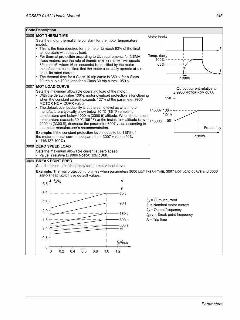
ACS550-01/U1 User’s Manual 145
3006 MOT THERM TIMESets the motor thermal time constant for the motor temperature model.• This is the time required for the motor to reach 63% of the final
temperature with steady load.• For thermal protection according to UL requirements for NEMA
class motors, use the rule of thumb: MOTOR THERM TIME equals 35 times t6, where t6 (in seconds) is specified by the motor manufacturer as the time that the motor can safely operate at six times its rated current.
• The thermal time for a Class 10 trip curve is 350 s, for a Class 20 trip curve 700 s, and for a Class 30 trip curve 1050 s.
3007 MOT LOAD CURVESets the maximum allowable operating load of the motor.• With the default value 100%, motor overload protection is functioning
when the constant current exceeds 127% of the parameter 9906 MOTOR NOM CURR value.
• The default overloadability is at the same level as what motor manufacturers typically allow below 30 °C (86 °F) ambient temperature and below 1000 m (3300 ft) altitude. When the ambient temperature exceeds 30 °C (86 °F) or the installation altitude is over 1000 m (3300 ft), decrease the parameter 3007 value according to the motor manufacturer’s recommendation.
Example: If the constant protection level needs to be 115% of the motor nominal current, set parameter 3007 value to 91% (= 115/127·100%).
3008 ZERO SPEED LOADSets the maximum allowable current at zero speed.• Value is relative to 9906 MOTOR NOM CURR.
3009 BREAK POINT FREQSets the break point frequency for the motor load curve. Example: Thermal protection trip times when parameters 3006 MOT THERM TIME, 3007 MOT LOAD CURVE and 3008
ZERO SPEED LOAD have default values.
Code Description
Temp. rise100%
63%
}
P 3006
Motor load
t
t
Frequency
150
50
P 3007
P 3008
P 3009
100 =127%
Output current relative to 9906 MOTOR NOM CURR
60 s
3.5
IO = Output current IN = Nominal motor currentfO = Output frequencyfBRK = Break point frequencyA = Trip time
3.0
2.5
2.0
1.5
1.0
0.5
00 0.2 0.4 0.8 1.0 1.2
90 s
180 s
300 s600 s
0.6
180 s
A
∞
IO/IN
fO/fBRK
Parameters
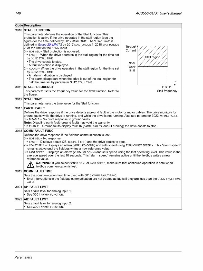
146 ACS550-01/U1 User’s Manual
3010 STALL FUNCTIONThis parameter defines the operation of the Stall function. This protection is active if the drive operates in the stall region (see the figure) for the time defined by 3012 STALL TIME. The “User Limit” is defined in Group 20: LIMITS by 2017 MAX TORQUE 1, 2018 MAX TORQUE 2, or the limit on the COMM input.0 = NOT SEL – Stall protection is not used.1 = FAULT – When the drive operates in the stall region for the time set
by 3012 STALL TIME: • The drive coasts to stop. • A fault indication is displayed.
2 = ALARM – When the drive operates in the stall region for the time set by 3012 STALL TIME:• An alarm indication is displayed. • The alarm disappears when the drive is out of the stall region for
half the time set by parameter 3012 STALL TIME.3011 STALL FREQUENCY
This parameter sets the frequency value for the Stall function. Refer to the figure.
3012 STALL TIMEThis parameter sets the time value for the Stall function.
3017 EARTH FAULTDefines the drive response if the drive detects a ground fault in the motor or motor cables. The drive monitors for ground faults while the drive is running, and while the drive is not running. Also see parameter 3023 WIRING FAULT.0 = DISABLE – No drive response to ground faults. Note: Disabling earth fault (ground fault) may void the warranty.1 = ENABLE – Ground faults display fault 16 (EARTH FAULT), and (if running) the drive coasts to stop.
3018 COMM FAULT FUNCDefines the drive response if the fieldbus communication is lost.0 = NOT SEL – No response.1 = FAULT – Displays a fault (28, SERIAL 1 ERR) and the drive coasts to stop.2 = CONST SP 7 – Displays an alarm (2005, I/O COMM) and sets speed using 1208 CONST SPEED 7. This “alarm speed”
remains active until the fieldbus writes a new reference value. 3 = LAST SPEED – Displays an alarm (2005, I/O COMM) and sets speed using the last operating level. This value is the
average speed over the last 10 seconds. This “alarm speed” remains active until the fieldbus writes a new reference value.
WARNING! If you select CONST SP 7, or LAST SPEED, make sure that continued operation is safe when fieldbus communication is lost.
3019 COMM FAULT TIMESets the communication fault time used with 3018 COMM FAULT FUNC.• Brief interruptions in the fieldbus communication are not treated as faults if they are less than the COMM FAULT TIME
value.3021 AI1 FAULT LIMIT
Sets a fault level for analog input 1. • See 3001 AI<MIN FUNCTION.
3022 AI2 FAULT LIMIT Sets a fault level for analog input 2. • See 3001 AI<MIN FUNCTION.
Code Description
95%
limitUser
Stall region
Torque/Current
f
Stall frequencyP 3011
Parameters
ACS550-01/U1 User’s Manual 147
3023 WIRING FAULTDefines the drive response to cross wiring faults and to ground faults detected when the drive is NOT running. When the drive is not running it monitors for:• Improper connections of input power to the drive output (the drive can display fault 35, OUTPUT WIRING if improper
connections are detected).• Ground faults (the drive can display fault 16, EARTH FAULT if a ground fault is detected). Also, see parameter 3017
EARTH FAULT.0 = DISABLE – No drive response to either of the above monitoring results.Note: Disabling wiring fault (ground fault) may void the warranty.1 = ENABLE – The drive displays faults when this monitoring detects problems.
3024 CB TEMP FAULTDefines the drive response to control board overheating. Not for drives with an OMIO control board. 0 = DISABLE – No response.1 = ENABLE – Displays fault 37 (CB OVERTEMP) and the drive coasts to stop.
Code Description
Parameters
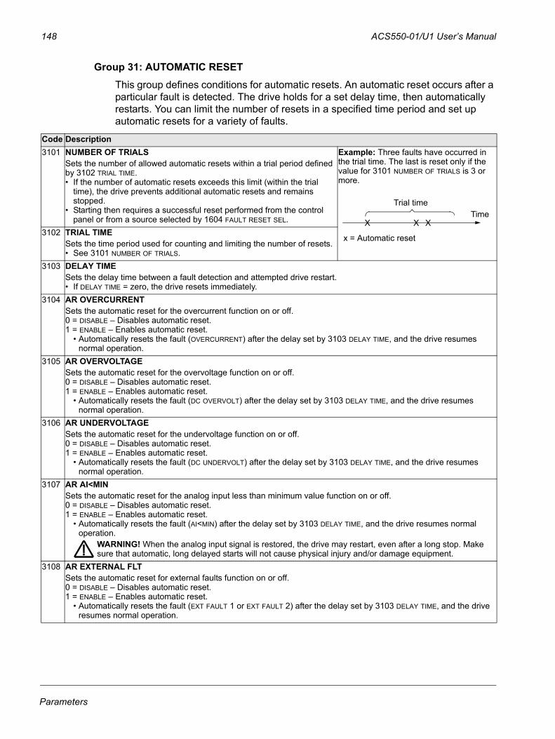
148 ACS550-01/U1 User’s Manual
Group 31: AUTOMATIC RESETThis group defines conditions for automatic resets. An automatic reset occurs after a particular fault is detected. The drive holds for a set delay time, then automatically restarts. You can limit the number of resets in a specified time period and set up automatic resets for a variety of faults.
Code Description3101 NUMBER OF TRIALS
Sets the number of allowed automatic resets within a trial period defined by 3102 TRIAL TIME. • If the number of automatic resets exceeds this limit (within the trial
time), the drive prevents additional automatic resets and remains stopped.
• Starting then requires a successful reset performed from the control panel or from a source selected by 1604 FAULT RESET SEL.
Example: Three faults have occurred in the trial time. The last is reset only if the value for 3101 NUMBER OF TRIALS is 3 or more.
3102 TRIAL TIMESets the time period used for counting and limiting the number of resets.• See 3101 NUMBER OF TRIALS.
3103 DELAY TIMESets the delay time between a fault detection and attempted drive restart.• If DELAY TIME = zero, the drive resets immediately.
3104 AR OVERCURRENTSets the automatic reset for the overcurrent function on or off.0 = DISABLE – Disables automatic reset.1 = ENABLE – Enables automatic reset.
• Automatically resets the fault (OVERCURRENT) after the delay set by 3103 DELAY TIME, and the drive resumes normal operation.
3105 AR OVERVOLTAGESets the automatic reset for the overvoltage function on or off.0 = DISABLE – Disables automatic reset.1 = ENABLE – Enables automatic reset.
• Automatically resets the fault (DC OVERVOLT) after the delay set by 3103 DELAY TIME, and the drive resumes normal operation.
3106 AR UNDERVOLTAGESets the automatic reset for the undervoltage function on or off.0 = DISABLE – Disables automatic reset.1 = ENABLE – Enables automatic reset.
• Automatically resets the fault (DC UNDERVOLT) after the delay set by 3103 DELAY TIME, and the drive resumes normal operation.
3107 AR AI<MINSets the automatic reset for the analog input less than minimum value function on or off.0 = DISABLE – Disables automatic reset.1 = ENABLE – Enables automatic reset.
• Automatically resets the fault (AI<MIN) after the delay set by 3103 DELAY TIME, and the drive resumes normal operation.
WARNING! When the analog input signal is restored, the drive may restart, even after a long stop. Make sure that automatic, long delayed starts will not cause physical injury and/or damage equipment.
3108 AR EXTERNAL FLTSets the automatic reset for external faults function on or off.0 = DISABLE – Disables automatic reset.1 = ENABLE – Enables automatic reset.
• Automatically resets the fault (EXT FAULT 1 or EXT FAULT 2) after the delay set by 3103 DELAY TIME, and the drive resumes normal operation.
X X XTime
Trial time
x = Automatic reset
Parameters
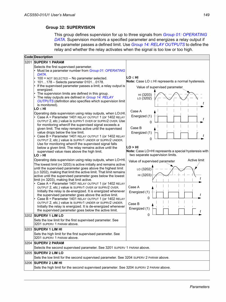
ACS550-01/U1 User’s Manual 149
Group 32: SUPERVISIONThis group defines supervision for up to three signals from Group 01: OPERATING DATA. Supervision monitors a specified parameter and energizes a relay output if the parameter passes a defined limit. Use Group 14: RELAY OUTPUTS to define the relay and whether the relay activates when the signal is too low or too high.
Code Description3201 SUPERV 1 PARAM
Selects the first supervised parameter.• Must be a parameter number from Group 01: OPERATING
DATA. • 100 = NOT SELECTED – No parameter selected.• 101…178 – Selects parameter 0101…0178.• If the supervised parameter passes a limit, a relay output is
energized.• The supervision limits are defined in this group.• The relay outputs are defined in Group 14: RELAY
OUTPUTS (definition also specifies which supervision limit is monitored).
LO ≤ HIOperating data supervision using relay outputs, when LO≤HI.• Case A = Parameter 1401 RELAY OUTPUT 1 (or 1402 RELAY
OUTPUT 2, etc.) value is SUPRV1 OVER or SUPRV2 OVER. Use for monitoring when/if the supervised signal exceeds a given limit. The relay remains active until the supervised value drops below the low limit.
• Case B = Parameter 1401 RELAY OUTPUT 1 (or 1402 RELAY OUTPUT 2, etc.) value is SUPRV1 UNDER or SUPRV2 UNDER. Use for monitoring when/if the supervised signal falls below a given limit. The relay remains active until the supervised value rises above the high limit.
LO > HIOperating data supervision using relay outputs, when LO>HI.The lowest limit (HI 3203) is active initially and remains active until the supervised parameter goes above the highest limit (LO 3202), making that limit the active limit. That limit remains active until the supervised parameter goes below the lowest limit (HI 3203), making that limit active.• Case A = Parameter 1401 RELAY OUTPUT 1 (or 1402 RELAY
OUTPUT 2, etc.) value is SUPRV1 OVER or SUPRV2 OVER. Initially the relay is de-energized. It is energized whenever the supervised parameter goes above the active limit.
• Case B = Parameter 1401 RELAY OUTPUT 1 (or 1402 RELAY OUTPUT 2, etc.) value is SUPRV1 UNDER or SUPRV2 UNDER. Initially the relay is energized. It is de-energized whenever the supervised parameter goes below the active limit.
LO ≤ HINote: Case LO ≤ HI represents a normal hysteresis.
LO > HINote: Case LO>HI represents a special hysteresis with
two separate supervision limits.
3202 SUPERV 1 LIM LOSets the low limit for the first supervised parameter. See 3201 SUPERV 1 PARAM above.
3203 SUPERV 1 LIM HISets the high limit for the first supervised parameter. See 3201 SUPERV 1 PARAM above.
3204 SUPERV 2 PARAMSelects the second supervised parameter. See 3201 SUPERV 1 PARAM above.
3205 SUPERV 2 LIM LOSets the low limit for the second supervised parameter. See 3204 SUPERV 2 PARAM above.
3206 SUPERV 2 LIM HISets the high limit for the second supervised parameter. See 3204 SUPERV 2 PARAM above.
Value of supervised parameter
Case A
0
Energized (1)
0
HI (3203)LO (3202)
Case BEnergized (1)
t
t
t
LO (3202)
HI (3203)
Value of supervised parameter
Case A
0
Energized (1)
0
Case BEnergized (1)
Active limit
t
t
t
Parameters
150 ACS550-01/U1 User’s Manual
3207 SUPERV 3 PARAMSelects the third supervised parameter. See 3201 SUPERV 1 PARAM above.
3208 SUPERV 3 LIM LOSets the low limit for the third supervised parameter. See 3207 SUPERV 3 PARAM above.
3209 SUPERV 3 LIM HISets the high limit for the third supervised parameter. See 3207 SUPERV 3 PARAM above.
Code Description
Parameters
ACS550-01/U1 User’s Manual 151
Group 33: INFORMATIONThis group provides access to information about the drive’s current programs: versions and test date.
Code Description3301 FIRMWARE
Contains the version of the drive’s firmware.3302 LOADING PACKAGE
Contains the version of the loading package.3303 TEST DATE
Contains the test date (yy.ww).3304 DRIVE RATING
Indicates the drive’s current and voltage rating. The format is XXXY, where:• XXX = The nominal current rating of the drive in amperes. If present, an “A” indicates a decimal point in the rating
for the current. For example XXX = 8A8 indicates a nominal current rating of 8.8 A.• Y = The voltage rating of the drive, where Y = :
• 2 indicates a 208…240 V rating.• 4 indicates a 380…480 V rating.• 6 indicates a 500…600 V rating.
3305 PARAMETER TABLEContains the version of the parameter table used in the drive.
Parameters
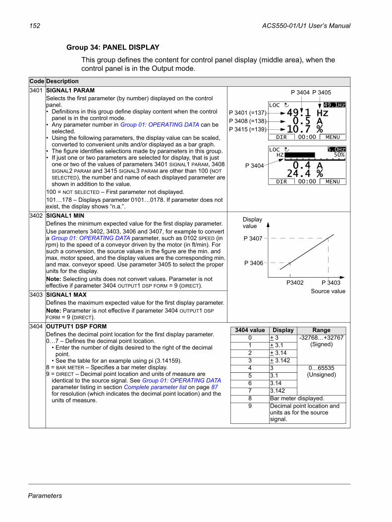
152 ACS550-01/U1 User’s Manual
Group 34: PANEL DISPLAYThis group defines the content for control panel display (middle area), when the control panel is in the Output mode.
Code Description3401 SIGNAL1 PARAM
Selects the first parameter (by number) displayed on the control panel.• Definitions in this group define display content when the control
panel is in the control mode.• Any parameter number in Group 01: OPERATING DATA can be
selected.• Using the following parameters, the display value can be scaled,
converted to convenient units and/or displayed as a bar graph.• The figure identifies selections made by parameters in this group.• If just one or two parameters are selected for display, that is just
one or two of the values of parameters 3401 SIGNAL1 PARAM, 3408 SIGNAL2 PARAM and 3415 SIGNAL3 PARAM are other than 100 (NOT SELECTED), the number and name of each displayed parameter are shown in addition to the value.
100 = NOT SELECTED – First parameter not displayed.101…178 – Displays parameter 0101…0178. If parameter does not exist, the display shows “n.a.”.
3402 SIGNAL1 MINDefines the minimum expected value for the first display parameter.Use parameters 3402, 3403, 3406 and 3407, for example to convert a Group 01: OPERATING DATA parameter, such as 0102 SPEED (in rpm) to the speed of a conveyor driven by the motor (in ft/min). For such a conversion, the source values in the figure are the min. and max. motor speed, and the display values are the corresponding min. and max. conveyor speed. Use parameter 3405 to select the proper units for the display.Note: Selecting units does not convert values. Parameter is not effective if parameter 3404 OUTPUT1 DSP FORM = 9 (DIRECT).
3403 SIGNAL1 MAXDefines the maximum expected value for the first display parameter.Note: Parameter is not effective if parameter 3404 OUTPUT1 DSP FORM = 9 (DIRECT).
3404 OUTPUT1 DSP FORMDefines the decimal point location for the first display parameter.0…7 – Defines the decimal point location.
• Enter the number of digits desired to the right of the decimal point.
• See the table for an example using pi (3.14159).8 = BAR METER – Specifies a bar meter display. 9 = DIRECT – Decimal point location and units of measure are
identical to the source signal. See Group 01: OPERATING DATA parameter listing in section Complete parameter list on page 87 for resolution (which indicates the decimal point location) and the units of measure.
5 A1 Hz
7 %10.0.
49.49.1HzLOC
DIR MENU00:00
P 3404 P 3405
4 A
4 %24.0.
5.0HzLOC
DIR MENU00:00
HZ 50%
P 3404
P 3401 (=137)P 3408 (=138)P 3415 (=139)
Source value
P 3407
P 3406
P 3403P3402
Display value
3404 value Display Range0 + 3 -32768…+32767
(Signed)1 + 3.12 + 3.143 + 3.1424 3 0…65535
(Unsigned)5 3.16 3.147 3.1428 Bar meter displayed.9 Decimal point location and
units as for the source signal.
Parameters
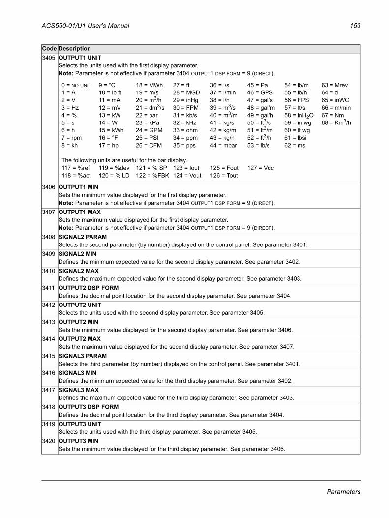
ACS550-01/U1 User’s Manual 153
3405 OUTPUT1 UNITSelects the units used with the first display parameter.Note: Parameter is not effective if parameter 3404 OUTPUT1 DSP FORM = 9 (DIRECT).
3406 OUTPUT1 MINSets the minimum value displayed for the first display parameter.Note: Parameter is not effective if parameter 3404 OUTPUT1 DSP FORM = 9 (DIRECT).
3407 OUTPUT1 MAXSets the maximum value displayed for the first display parameter.Note: Parameter is not effective if parameter 3404 OUTPUT1 DSP FORM = 9 (DIRECT).
3408 SIGNAL2 PARAMSelects the second parameter (by number) displayed on the control panel. See parameter 3401.
3409 SIGNAL2 MINDefines the minimum expected value for the second display parameter. See parameter 3402.
3410 SIGNAL2 MAXDefines the maximum expected value for the second display parameter. See parameter 3403.
3411 OUTPUT2 DSP FORMDefines the decimal point location for the second display parameter. See parameter 3404.
3412 OUTPUT2 UNITSelects the units used with the second display parameter. See parameter 3405.
3413 OUTPUT2 MINSets the minimum value displayed for the second display parameter. See parameter 3406.
3414 OUTPUT2 MAXSets the maximum value displayed for the second display parameter. See parameter 3407.
3415 SIGNAL3 PARAMSelects the third parameter (by number) displayed on the control panel. See parameter 3401.
3416 SIGNAL3 MINDefines the minimum expected value for the third display parameter. See parameter 3402.
3417 SIGNAL3 MAXDefines the maximum expected value for the third display parameter. See parameter 3403.
3418 OUTPUT3 DSP FORMDefines the decimal point location for the third display parameter. See parameter 3404.
3419 OUTPUT3 UNITSelects the units used with the third display parameter. See parameter 3405.
3420 OUTPUT3 MINSets the minimum value displayed for the third display parameter. See parameter 3406.
Code Description
0 = NO UNIT 9 = °C 18 = MWh 27 = ft 36 = l/s 45 = Pa 54 = lb/m 63 = Mrev1 = A 10 = lb ft 19 = m/s 28 = MGD 37 = l/min 46 = GPS 55 = lb/h 64 = d2 = V 11 = mA 20 = m3/h 29 = inHg 38 = l/h 47 = gal/s 56 = FPS 65 = inWC3 = Hz 12 = mV 21 = dm3/s 30 = FPM 39 = m3/s 48 = gal/m 57 = ft/s 66 = m/min4 = % 13 = kW 22 = bar 31 = kb/s 40 = m3/m 49 = gal/h 58 = inH2O 67 = Nm5 = s 14 = W 23 = kPa 32 = kHz 41 = kg/s 50 = ft3/s 59 = in wg 68 = Km3/h6 = h 15 = kWh 24 = GPM 33 = ohm 42 = kg/m 51 = ft3/m 60 = ft wg7 = rpm 16 = °F 25 = PSI 34 = ppm 43 = kg/h 52 = ft3/h 61 = lbsi8 = kh 17 = hp 26 = CFM 35 = pps 44 = mbar 53 = lb/s 62 = ms
The following units are useful for the bar display.117 = %ref 119 = %dev 121 = % SP 123 = Iout 125 = Fout 127 = Vdc118 = %act 120 = % LD 122 = %FBK 124 = Vout 126 = Tout
Parameters

154 ACS550-01/U1 User’s Manual
3421 OUTPUT3 MAXSets the maximum value displayed for the third display parameter. See parameter 3407.
Code Description
Parameters
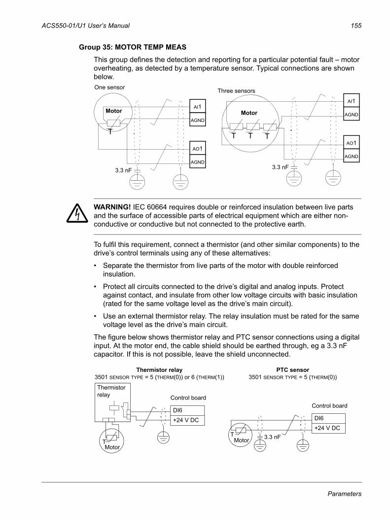
ACS550-01/U1 User’s Manual 155
Group 35: MOTOR TEMP MEASThis group defines the detection and reporting for a particular potential fault – motor overheating, as detected by a temperature sensor. Typical connections are shown below.
WARNING! IEC 60664 requires double or reinforced insulation between live parts and the surface of accessible parts of electrical equipment which are either non-conductive or conductive but not connected to the protective earth.
To fulfil this requirement, connect a thermistor (and other similar components) to the drive’s control terminals using any of these alternatives:
• Separate the thermistor from live parts of the motor with double reinforced insulation.
• Protect all circuits connected to the drive’s digital and analog inputs. Protect against contact, and insulate from other low voltage circuits with basic insulation (rated for the same voltage level as the drive’s main circuit).
• Use an external thermistor relay. The relay insulation must be rated for the same voltage level as the drive’s main circuit.
The figure below shows thermistor relay and PTC sensor connections using a digital input. At the motor end, the cable shield should be earthed through, eg a 3.3 nF capacitor. If this is not possible, leave the shield unconnected.
Motor
T
Motor
TTT
One sensor Three sensors
AI1
AGND
AO1
AGND
AI1
AGND
AO1
AGND
3.3 nF3.3 nF
MotorT
MotorT
Thermistorrelay Control board
DI6
+24 V DC
Control board
DI6
+24 V DC3.3 nF
Thermistor relay3501 SENSOR TYPE = 5 (THERM(0)) or 6 (THERM(1))
PTC sensor3501 SENSOR TYPE = 5 (THERM(0))
Parameters
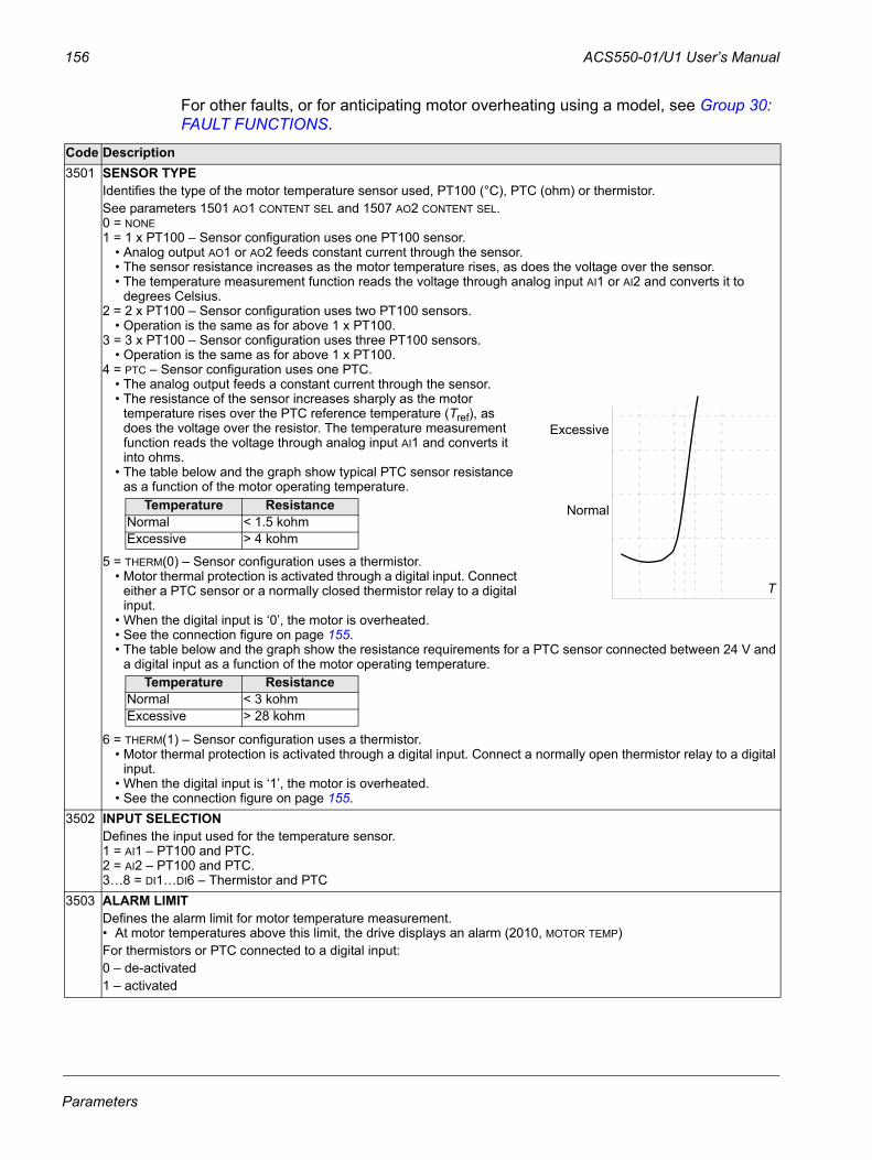
156 ACS550-01/U1 User’s Manual
For other faults, or for anticipating motor overheating using a model, see Group 30: FAULT FUNCTIONS.
Code Description3501 SENSOR TYPE
Identifies the type of the motor temperature sensor used, PT100 (°C), PTC (ohm) or thermistor. See parameters 1501 AO1 CONTENT SEL and 1507 AO2 CONTENT SEL.0 = NONE1 = 1 x PT100 – Sensor configuration uses one PT100 sensor.
• Analog output AO1 or AO2 feeds constant current through the sensor. • The sensor resistance increases as the motor temperature rises, as does the voltage over the sensor.• The temperature measurement function reads the voltage through analog input AI1 or AI2 and converts it to
degrees Celsius.2 = 2 x PT100 – Sensor configuration uses two PT100 sensors.
• Operation is the same as for above 1 x PT100. 3 = 3 x PT100 – Sensor configuration uses three PT100 sensors.
• Operation is the same as for above 1 x PT100. 4 = PTC – Sensor configuration uses one PTC.
• The analog output feeds a constant current through the sensor. • The resistance of the sensor increases sharply as the motor
temperature rises over the PTC reference temperature (Tref), as does the voltage over the resistor. The temperature measurement function reads the voltage through analog input AI1 and converts it into ohms.
• The table below and the graph show typical PTC sensor resistance as a function of the motor operating temperature.
5 = THERM(0) – Sensor configuration uses a thermistor. • Motor thermal protection is activated through a digital input. Connect
either a PTC sensor or a normally closed thermistor relay to a digital input.
• When the digital input is ‘0’, the motor is overheated.• See the connection figure on page 155.• The table below and the graph show the resistance requirements for a PTC sensor connected between 24 V and
a digital input as a function of the motor operating temperature.
6 = THERM(1) – Sensor configuration uses a thermistor.• Motor thermal protection is activated through a digital input. Connect a normally open thermistor relay to a digital
input. • When the digital input is ‘1’, the motor is overheated.• See the connection figure on page 155.
3502 INPUT SELECTIONDefines the input used for the temperature sensor.1 = AI1 – PT100 and PTC.2 = AI2 – PT100 and PTC.3…8 = DI1…DI6 – Thermistor and PTC
3503 ALARM LIMITDefines the alarm limit for motor temperature measurement. • At motor temperatures above this limit, the drive displays an alarm (2010, MOTOR TEMP)For thermistors or PTC connected to a digital input:0 – de-activated1 – activated
T
Excessive
NormalTemperature ResistanceNormal < 1.5 kohmExcessive > 4 kohm
Temperature ResistanceNormal < 3 kohmExcessive > 28 kohm
Parameters

ACS550-01/U1 User’s Manual 157
3504 FAULT LIMITDefines the fault limit for motor temperature measurement. • At motor temperatures above this limit, the drive displays a fault (9, MOT OVERTEMP) and stops the drive.For thermistors or PTC connected to a digital input:0 – de-activated1 – activated
Code Description
Parameters
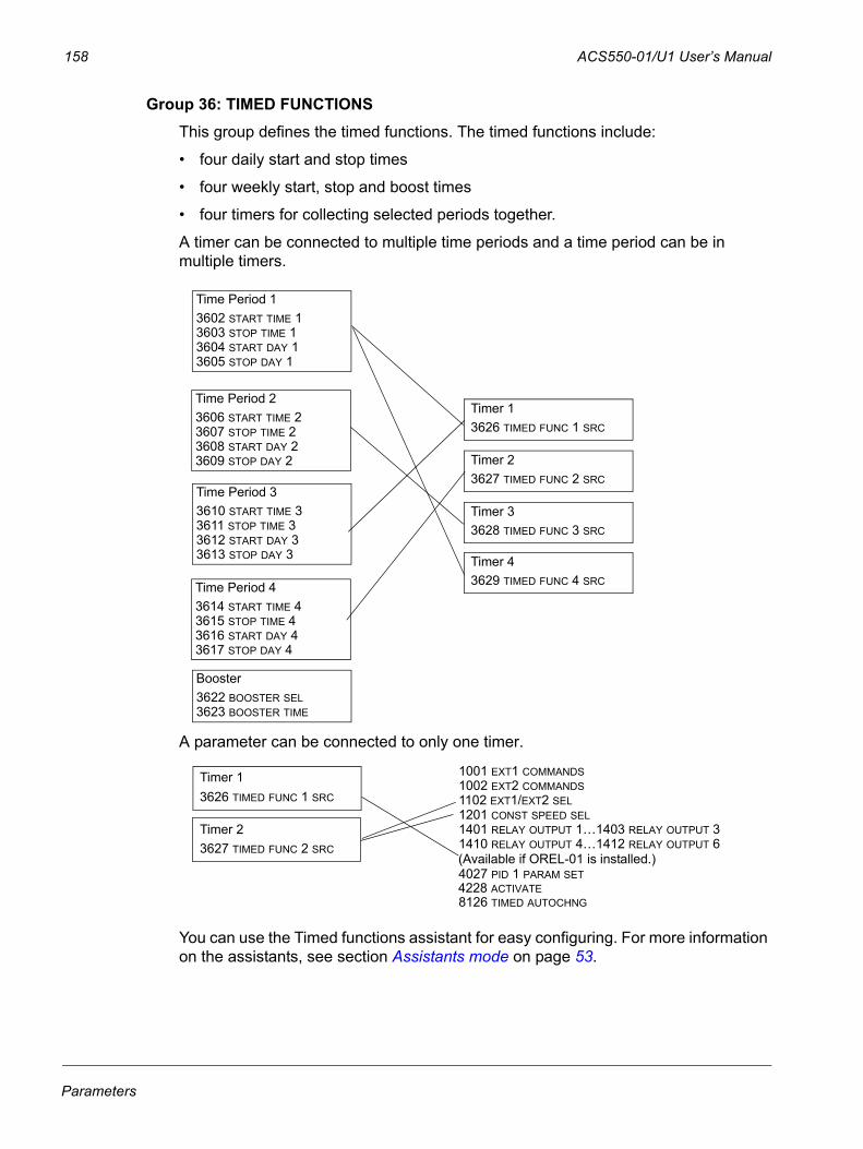
158 ACS550-01/U1 User’s Manual
Group 36: TIMED FUNCTIONSThis group defines the timed functions. The timed functions include:
• four daily start and stop times
• four weekly start, stop and boost times
• four timers for collecting selected periods together.
A timer can be connected to multiple time periods and a time period can be in multiple timers.
A parameter can be connected to only one timer.
You can use the Timed functions assistant for easy configuring. For more information on the assistants, see section Assistants mode on page 53.
Time Period 13602 START TIME 13603 STOP TIME 13604 START DAY 13605 STOP DAY 1
Time Period 43614 START TIME 43615 STOP TIME 43616 START DAY 43617 STOP DAY 4
Time Period 33610 START TIME 33611 STOP TIME 33612 START DAY 33613 STOP DAY 3
Time Period 23606 START TIME 23607 STOP TIME 23608 START DAY 23609 STOP DAY 2
Booster 3622 BOOSTER SEL3623 BOOSTER TIME
Timer 13626 TIMED FUNC 1 SRC
Timer 23627 TIMED FUNC 2 SRC
Timer 33628 TIMED FUNC 3 SRC
Timer 43629 TIMED FUNC 4 SRC
Timer 23627 TIMED FUNC 2 SRC
1001 EXT1 COMMANDS1002 EXT2 COMMANDS1102 EXT1/EXT2 SEL1201 CONST SPEED SEL1401 RELAY OUTPUT 1…1403 RELAY OUTPUT 3
4027 PID 1 PARAM SET
Timer 13626 TIMED FUNC 1 SRC
8126 TIMED AUTOCHNG
1410 RELAY OUTPUT 4…1412 RELAY OUTPUT 6
4228 ACTIVATE
(Available if OREL-01 is installed.)
Parameters
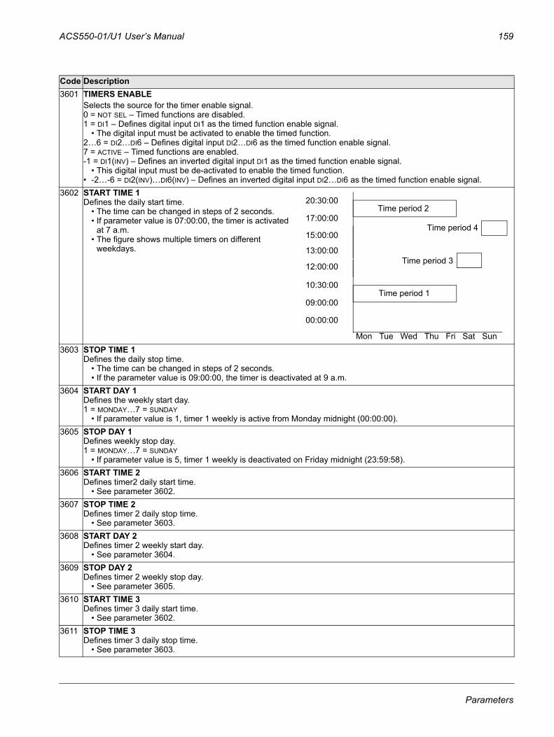
ACS550-01/U1 User’s Manual 159
Code Description3601 TIMERS ENABLE
Selects the source for the timer enable signal.0 = NOT SEL – Timed functions are disabled.1 = DI1 – Defines digital input DI1 as the timed function enable signal.
• The digital input must be activated to enable the timed function.2…6 = DI2…DI6 – Defines digital input DI2…DI6 as the timed function enable signal.7 = ACTIVE – Timed functions are enabled.-1 = DI1(INV) – Defines an inverted digital input DI1 as the timed function enable signal.
• This digital input must be de-activated to enable the timed function.• -2…-6 = DI2(INV)…DI6(INV) – Defines an inverted digital input DI2…DI6 as the timed function enable signal.
3602 START TIME 1Defines the daily start time.
• The time can be changed in steps of 2 seconds.• If parameter value is 07:00:00, the timer is activated
at 7 a.m.• The figure shows multiple timers on different
weekdays.
3603 STOP TIME 1Defines the daily stop time.
• The time can be changed in steps of 2 seconds.• If the parameter value is 09:00:00, the timer is deactivated at 9 a.m.
3604 START DAY 1Defines the weekly start day.1 = MONDAY…7 = SUNDAY
• If parameter value is 1, timer 1 weekly is active from Monday midnight (00:00:00).3605 STOP DAY 1
Defines weekly stop day.1 = MONDAY…7 = SUNDAY
• If parameter value is 5, timer 1 weekly is deactivated on Friday midnight (23:59:58).3606 START TIME 2
Defines timer2 daily start time.• See parameter 3602.
3607 STOP TIME 2Defines timer 2 daily stop time.
• See parameter 3603.3608 START DAY 2
Defines timer 2 weekly start day.• See parameter 3604.
3609 STOP DAY 2Defines timer 2 weekly stop day.
• See parameter 3605.3610 START TIME 3
Defines timer 3 daily start time.• See parameter 3602.
3611 STOP TIME 3Defines timer 3 daily stop time.
• See parameter 3603.
Mon Tue Wed Thu Fri Sat Sun
00:00:00
09:00:00
10:30:00
12:00:00
13:00:00
15:00:00
17:00:00
20:30:00
Time period 1
Time period 2
Time period 3
Time period 4
Parameters
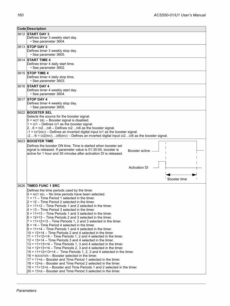
160 ACS550-01/U1 User’s Manual
3612 START DAY 3Defines timer 3 weekly start day.
• See parameter 3604.3613 STOP DAY 3
Defines timer 3 weekly stop day.• See parameter 3605.
3614 START TIME 4Defines timer 4 daily start time.
• See parameter 3602.3615 STOP TIME 4
Defines timer 4 daily stop time.• See parameter 3603.
3616 START DAY 4Defines timer 4 weekly start day.
• See parameter 3604.3617 STOP DAY 4
Defines timer 4 weekly stop day.• See parameter 3605.
3622 BOOSTER SEL Selects the source for the booster signal. 0 = NOT SEL – Booster signal is disabled.1 = DI1 – Defines DI1 as the booster signal.2…6 = DI2…DI6 – Defines DI2…DI6 as the booster signal.-1 = DI1(INV) – Defines an inverted digital input DI1 as the booster signal.-2…-6 = DI2(INV)…DI6(INV) – Defines an inverted digital input DI2…DI6 as the booster signal.
3623 BOOSTER TIMEDefines the booster ON time. Time is started when booster sel signal is released. If parameter value is 01:30:00, booster is active for 1 hour and 30 minutes after activation DI is released.
3626 TIMED FUNC 1 SRCDefines the time periods used by the timer.0 = NOT SEL – No time periods have been selected.1 = T1 – Time Period 1 selected in the timer.2 = T2 – Time Period 2 selected in the timer.3 = T1+T2 – Time Periods 1 and 2 selected in the timer.4 = T3 – Time Period 3 selected in the timer.5 = T1+T3 – Time Periods 1 and 3 selected in the timer.6 = T2+T3 – Time Periods 2 and 3 selected in the timer.7 = T1+T2+T3 – Time Periods 1, 2 and 3 selected in the timer.8 = T4 – Time Period 4 selected in the timer.9 = T1+T4 – Time Periods 1 and 4 selected in the timer.10 = T2+T4 – Time Periods 2 and 4 selected in the timer.11 = T1+T2+T4 – Time Periods 1, 2 and 4 selected in the timer.12 = T3+T4 – Time Periods 3 and 4 selected in the timer.13 = T1+T3+T4 – Time Periods 1, 3 and 4 selected in the timer.14 = T2+T3+T4 – Time Periods 2, 3 and 4 selected in the timer.15 = T1+T2+T3+T4 – Time Periods 1, 2, 3 and 4 selected in the timer.16 = BOOSTER – Booster selected in the timer.17 = T1+B – Booster and Time Period 1 selected in the timer.18 = T2+B – Booster and Time Period 2 selected in the timer.19 = T1+T2+B – Booster and Time Periods 1 and 2 selected in the timer.20 = T3+B – Booster and Time Period 3 selected in the timer.
Code Description
Booster active
Activation DI
Booster time
Parameters
ACS550-01/U1 User’s Manual 161
21 = T1+T3+B – Booster and Time Periods 1 and 3 selected in the timer.22 = T2+T3+B – Booster and Time Periods 2 and 3 selected in the timer.23 = T1+T2+T3+B – Booster and Time Periods 1, 2 and 3 selected in the timer.24 = T4+B – Booster and Time Period 4 selected in the timer.25 = T1+T4+B – Booster and Time Periods 1 and 4 selected in the timer.26 = T2+T4+B – Booster and Time Periods 2 and 4 selected in the timer.27 = T1+T2+T4+B – Booster and Time Periods 1, 2 and 4 selected in the timer.28 = T3+T4+B – Booster and Time Periods 3 and 4 selected in the timer.29 = T1+T3+T4+B – Booster and Time Periods 1, 3 and 4 selected in the timer.30 = T2+T3+T4+B – Booster and Time Periods 2, 3 and 4 selected in the timer.31 = T1+2+3+4+B – Booster and Time Periods 1, 2, 3 and 4 selected in the timer.
3627 TIMED FUNC 2 SRC• See parameter 3626.
3628 TIMED FUNC 3 SRC• See parameter 3626.
3629 TIMED FUNC 4 SRC• See parameter 3626.
Code Description
Parameters
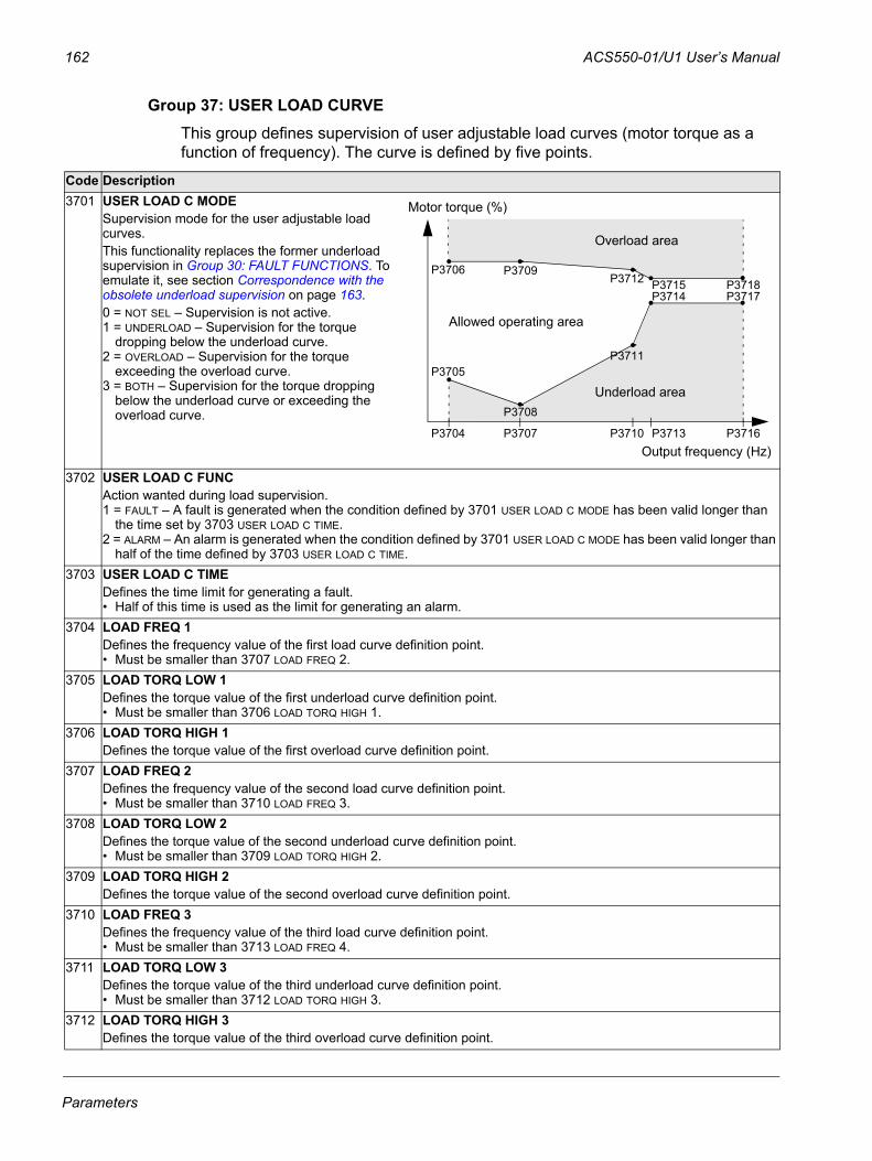
162 ACS550-01/U1 User’s Manual
Group 37: USER LOAD CURVEThis group defines supervision of user adjustable load curves (motor torque as a function of frequency). The curve is defined by five points.
Code Description3701 USER LOAD C MODE
Supervision mode for the user adjustable load curves. This functionality replaces the former underload supervision in Group 30: FAULT FUNCTIONS. To emulate it, see section Correspondence with the obsolete underload supervision on page 163.0 = NOT SEL – Supervision is not active.1 = UNDERLOAD – Supervision for the torque
dropping below the underload curve.2 = OVERLOAD – Supervision for the torque
exceeding the overload curve.3 = BOTH – Supervision for the torque dropping
below the underload curve or exceeding the overload curve.
3702 USER LOAD C FUNCAction wanted during load supervision.1 = FAULT – A fault is generated when the condition defined by 3701 USER LOAD C MODE has been valid longer than
the time set by 3703 USER LOAD C TIME.2 = ALARM – An alarm is generated when the condition defined by 3701 USER LOAD C MODE has been valid longer than
half of the time defined by 3703 USER LOAD C TIME. 3703 USER LOAD C TIME
Defines the time limit for generating a fault. • Half of this time is used as the limit for generating an alarm.
3704 LOAD FREQ 1Defines the frequency value of the first load curve definition point. • Must be smaller than 3707 LOAD FREQ 2.
3705 LOAD TORQ LOW 1Defines the torque value of the first underload curve definition point. • Must be smaller than 3706 LOAD TORQ HIGH 1.
3706 LOAD TORQ HIGH 1Defines the torque value of the first overload curve definition point.
3707 LOAD FREQ 2Defines the frequency value of the second load curve definition point. • Must be smaller than 3710 LOAD FREQ 3.
3708 LOAD TORQ LOW 2Defines the torque value of the second underload curve definition point. • Must be smaller than 3709 LOAD TORQ HIGH 2.
3709 LOAD TORQ HIGH 2Defines the torque value of the second overload curve definition point.
3710 LOAD FREQ 3Defines the frequency value of the third load curve definition point.• Must be smaller than 3713 LOAD FREQ 4.
3711 LOAD TORQ LOW 3Defines the torque value of the third underload curve definition point. • Must be smaller than 3712 LOAD TORQ HIGH 3.
3712 LOAD TORQ HIGH 3Defines the torque value of the third overload curve definition point.
Overload area
Underload area
Allowed operating area
P3706
P3705
P3704
P3709
P3708
P3707
P3712
P3711
P3710
P3715P3714
P3713
P3718P3717
P3716
Motor torque (%)
Output frequency (Hz)
Parameters
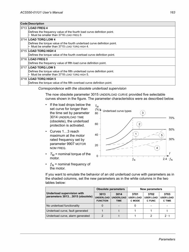
ACS550-01/U1 User’s Manual 163
Correspondence with the obsolete underload supervision
The now obsolete parameter 3015 UNDERLOAD CURVE provided five selectable curves shown in the figure. The parameter characteristics were as described below.
• If the load drops below the set curve for longer than the time set by parameter 3014 UNDERLOAD TIME (obsolete), the underload protection is activated.
• Curves 1…3 reach maximum at the motor rated frequency set by parameter 9907 MOTOR NOM FREQ.
• TM = nominal torque of the motor.
• ƒN = nominal frequency of the motor.
If you want to emulate the behavior of an old underload curve with parameters as in the shaded columns, set the new parameters as in the white columns in the two tables below:
3713 LOAD FREQ 4Defines the frequency value of the fourth load curve definition point.• Must be smaller than 3716 LOAD FREQ 5
3714 LOAD TORQ LOW 4Defines the torque value of the fourth underload curve definition point. • Must be smaller than 3715 LOAD TORQ HIGH 4.
3715 LOAD TORQ HIGH 4Defines the torque value of the fourth overload curve definition point.
3716 LOAD FREQ 5Defines the frequency value of fifth load curve definition point.
3717 LOAD TORQ LOW 5Defines the torque value of the fifth underload curve definition point. • Must be smaller than 3718 LOAD TORQ HIGH 5.
3718 LOAD TORQ HIGH 5Defines the torque value of the fifth overload curve definition point.
Underload supervision with parameters 3013…3015 (obsolete)
Obsolete parameters New parameters
3013UNDERLOAD
FUNCTION
3014 UNDERLOAD
TIME
3701USER LOAD
C MODE
3702USER LOAD
C FUNC
3703USER LOAD
C TIME
No underload functionality 0 - 0 - -
Underload curve, fault generated 1 t 1 1 t
Underload curve, alarm generated 2 t 1 2 2 · t
Code Description
80
60
40
20
02.4 · ƒN
3
2
1 5
4
TM
70%
50%
30%
ƒN
(%) Underload curve types
f
Parameters
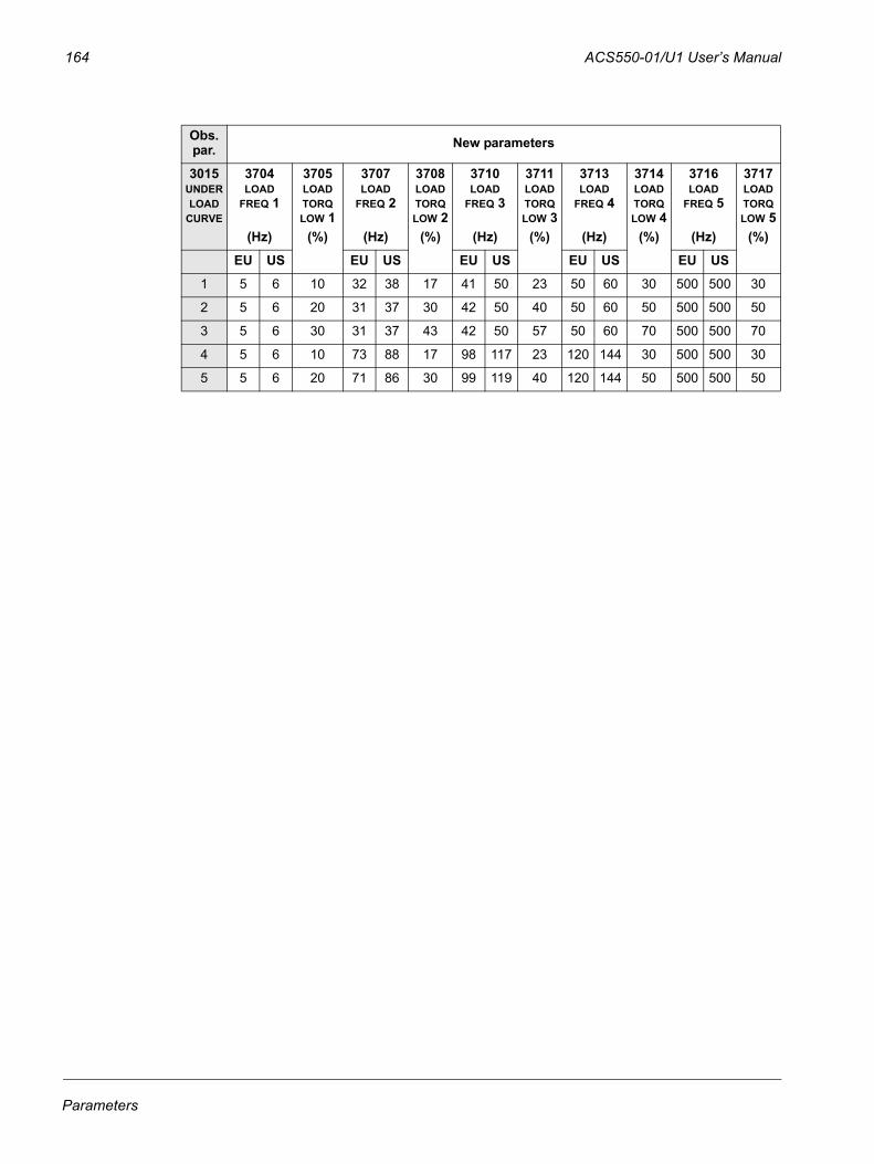
164 ACS550-01/U1 User’s Manual
Obs. par. New parameters
3015 UNDERLOAD
CURVE
3704LOAD
FREQ 1
(Hz)
3705LOAD TORQ LOW 1
(%)
3707LOAD
FREQ 2
(Hz)
3708LOAD TORQ LOW 2
(%)
3710LOAD
FREQ 3
(Hz)
3711LOAD TORQ LOW 3
(%)
3713LOAD
FREQ 4
(Hz)
3714LOAD TORQ LOW 4
(%)
3716LOAD
FREQ 5
(Hz)
3717LOAD TORQ LOW 5
(%)
EU US EU US EU US EU US EU US
1 5 6 10 32 38 17 41 50 23 50 60 30 500 500 30
2 5 6 20 31 37 30 42 50 40 50 60 50 500 500 50
3 5 6 30 31 37 43 42 50 57 50 60 70 500 500 70
4 5 6 10 73 88 17 98 117 23 120 144 30 500 500 30
5 5 6 20 71 86 30 99 119 40 120 144 50 500 500 50
Parameters
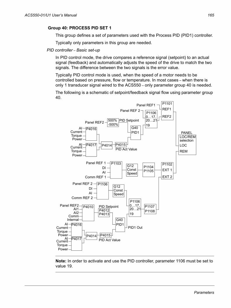
ACS550-01/U1 User’s Manual 165
Group 40: PROCESS PID SET 1 This group defines a set of parameters used with the Process PID (PID1) controller.
Typically only parameters in this group are needed.
PID controller – Basic set-up
In PID control mode, the drive compares a reference signal (setpoint) to an actual signal (feedback) and automatically adjusts the speed of the drive to match the two signals. The difference between the two signals is the error value.
Typically PID control mode is used, when the speed of a motor needs to be controlled based on pressure, flow or temperature. In most cases – when there is only 1 transducer signal wired to the ACS550 – only parameter group 40 is needed.
The following is a schematic of setpoint/feedback signal flow using parameter group 40.
Note: In order to activate and use the PID controller, parameter 1106 must be set to value 19.
Panel REF1 P1101REF1
REF2P1106Panel REF 2
P1102EXT 1
EXT 2
P1104P1105
P1103Panel REF 1DIAI
Comm REF 1
P1107P1108
G12ConstSpeed
PANELG40PID1
Panel REF2
AICurrentTorquePower
AICurrentTorquePower
PID Setpoint
PID Act Value
P4016
P4015P4014P4017
500%-500%
G40PID1AI
CurrentTorquePower
AICurrentTorquePower
PID Act Value
P4016
P4015P4014P4017
P1106Panel REF 2DIAI
Comm REF 2
G12ConstSpeed
Panel REF2
InternalComm
AI2AI1
PID SetpointP4010P4012P4013
PID1 Out
19
LOC/REMselectionLOC
REM
0…17,20…21
P1106
19
0…17,20…21
Parameters
166 ACS550-01/U1 User’s Manual
PID controller – Advanced
The ACS550 has two separate PID controllers:
• Process PID (PID1) and
• External PID (PID2)
Process PID (PID1) has 2 separate sets of parameters:
• Process PID (PID1) SET1, defined in Group 40: PROCESS PID SET 1 and
• Process PID (PID1) SET2, defined in Group 41: PROCESS PID SET 2
You can select between the two different sets by using parameter 4027.
Typically two different PID controller sets are used when the load of the motor changes considerably from one situation to another.
You can use External PID (PID2), defined in Group 42: EXT / TRIM PID, in two different ways:
• Instead of using additional PID controller hardware, you can set outputs of the ACS550 to control a field instrument like a damper or a valve. In this case, set parameter 4230 to value 0. (0 is the default value.)
• You can use External PID (PID2) to trim or fine-tune the speed of the ACS550.
Code Description4001 GAIN
Defines the PID controller’s gain. • The setting range is 0.1… 100. • At 0.1, the PID controller output changes one-tenth as much as the error value.• At 100, the PID controller output changes one hundred times as much as the error value.Use the proportional gain and integration time values to adjust the responsiveness of the system. • A low value for proportional gain and a high value for integral time ensures stable operation, but provides sluggish
response. If the proportional gain value is too large or the integral time too short, the system can become unstable. Procedure:• Initially, set:
• 4001 GAIN = 0.1.• 4002 INTEGRATION TIME = 20 seconds.
• Start the system and see if it reaches the setpoint quickly while maintaining stable operation. If not, increase GAIN (4001) until the actual signal (or drive speed) oscillates constantly. It may be necessary to start and stop the drive to induce this oscillation.
• Reduce GAIN (4001) until the oscillation stops.• Set GAIN (4001) to 0.4 to 0.6 times the above value. • Decrease the INTEGRATION TIME (4002) until the feedback signal (or drive speed) oscillates constantly. It may be
necessary to start and stop the drive to induce this oscillation. • Increase INTEGRATION TIME (4002) until the oscillation stops. • Set INTEGRATION TIME (4002) to 1.15 to 1.5 times the above value. • If the feedback signal contains high frequency noise, increase the value of parameter 1303 FILTER AI1 or 1306
FILTER AI2 until the noise is filtered from the signal.
Parameters
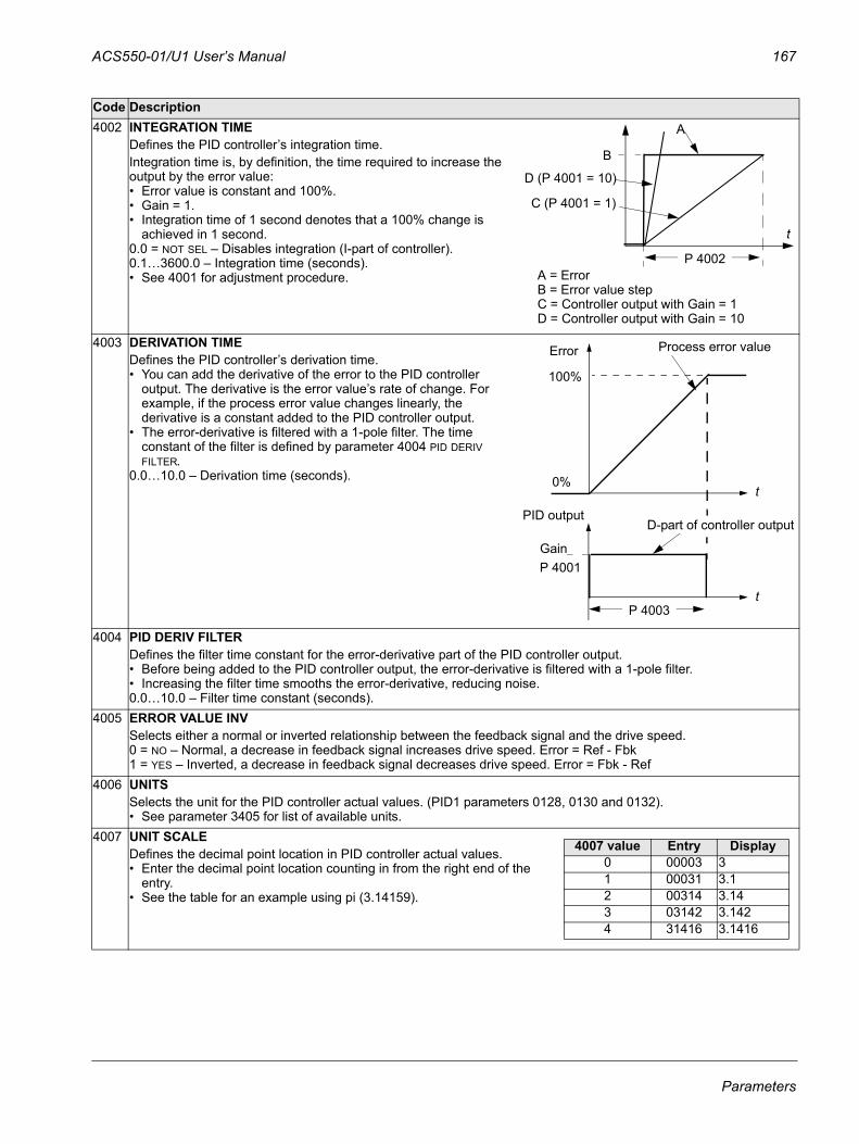
ACS550-01/U1 User’s Manual 167
4002 INTEGRATION TIMEDefines the PID controller’s integration time. Integration time is, by definition, the time required to increase the output by the error value:• Error value is constant and 100%.• Gain = 1. • Integration time of 1 second denotes that a 100% change is
achieved in 1 second. 0.0 = NOT SEL – Disables integration (I-part of controller).0.1…3600.0 – Integration time (seconds).• See 4001 for adjustment procedure.
4003 DERIVATION TIMEDefines the PID controller’s derivation time.• You can add the derivative of the error to the PID controller
output. The derivative is the error value’s rate of change. For example, if the process error value changes linearly, the derivative is a constant added to the PID controller output.
• The error-derivative is filtered with a 1-pole filter. The time constant of the filter is defined by parameter 4004 PID DERIV FILTER.
0.0…10.0 – Derivation time (seconds).
4004 PID DERIV FILTERDefines the filter time constant for the error-derivative part of the PID controller output.• Before being added to the PID controller output, the error-derivative is filtered with a 1-pole filter. • Increasing the filter time smooths the error-derivative, reducing noise.0.0…10.0 – Filter time constant (seconds).
4005 ERROR VALUE INVSelects either a normal or inverted relationship between the feedback signal and the drive speed.0 = NO – Normal, a decrease in feedback signal increases drive speed. Error = Ref - Fbk1 = YES – Inverted, a decrease in feedback signal decreases drive speed. Error = Fbk - Ref
4006 UNITSSelects the unit for the PID controller actual values. (PID1 parameters 0128, 0130 and 0132).• See parameter 3405 for list of available units.
4007 UNIT SCALEDefines the decimal point location in PID controller actual values.• Enter the decimal point location counting in from the right end of the
entry.• See the table for an example using pi (3.14159).
Code Description
P 4002
A
C (P 4001 = 1)
B
A = ErrorB = Error value stepC = Controller output with Gain = 1 D = Controller output with Gain = 10
D (P 4001 = 10)
t
100%
Gain
Process error value
P 4003
D-part of controller outputPID output
Error
0%
P 4001
t
t
4007 value Entry Display0 00003 31 00031 3.12 00314 3.143 03142 3.1424 31416 3.1416
Parameters
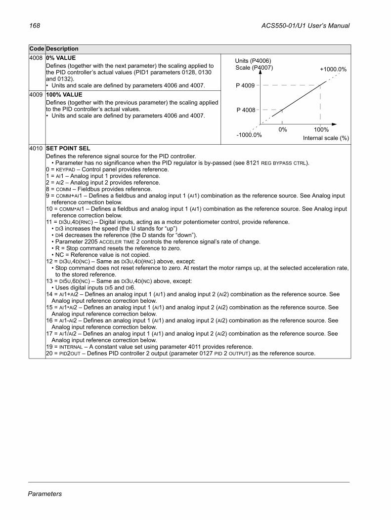
168 ACS550-01/U1 User’s Manual
4008 0% VALUEDefines (together with the next parameter) the scaling applied to the PID controller’s actual values (PID1 parameters 0128, 0130 and 0132). • Units and scale are defined by parameters 4006 and 4007.
4009 100% VALUEDefines (together with the previous parameter) the scaling applied to the PID controller’s actual values. • Units and scale are defined by parameters 4006 and 4007.
4010 SET POINT SELDefines the reference signal source for the PID controller.
• Parameter has no significance when the PID regulator is by-passed (see 8121 REG BYPASS CTRL).0 = KEYPAD – Control panel provides reference.1 = AI1 – Analog input 1 provides reference.2 = AI2 – Analog input 2 provides reference.8 = COMM – Fieldbus provides reference.9 = COMM+AI1 – Defines a fieldbus and analog input 1 (AI1) combination as the reference source. See Analog input
reference correction below.10 = COMM*AI1 – Defines a fieldbus and analog input 1 (AI1) combination as the reference source. See Analog input
reference correction below.11 = DI3U,4D(RNC) – Digital inputs, acting as a motor potentiometer control, provide reference.
• DI3 increases the speed (the U stands for “up”)• DI4 decreases the reference (the D stands for “down”). • Parameter 2205 ACCELER TIME 2 controls the reference signal’s rate of change.• R = Stop command resets the reference to zero.• NC = Reference value is not copied.
12 = DI3U,4D(NC) – Same as DI3U,4D(RNC) above, except:• Stop command does not reset reference to zero. At restart the motor ramps up, at the selected acceleration rate,
to the stored reference. 13 = DI5U,6D(NC) – Same as DI3U,4D(NC) above, except:
• Uses digital inputs DI5 and DI6.14 = AI1+AI2 – Defines an analog input 1 (AI1) and analog input 2 (AI2) combination as the reference source. See
Analog input reference correction below.15 = AI1*AI2 – Defines an analog input 1 (AI1) and analog input 2 (AI2) combination as the reference source. See
Analog input reference correction below.16 = AI1-AI2 – Defines an analog input 1 (AI1) and analog input 2 (AI2) combination as the reference source. See
Analog input reference correction below.17 = AI1/AI2 – Defines an analog input 1 (AI1) and analog input 2 (AI2) combination as the reference source. See
Analog input reference correction below.19 = INTERNAL – A constant value set using parameter 4011 provides reference.20 = PID2OUT – Defines PID controller 2 output (parameter 0127 PID 2 OUTPUT) as the reference source.
Code Description
Internal scale (%)
P 4009
P 4008
100% 0%
Units (P4006)Scale (P4007)
-1000.0%
+1000.0%
Parameters
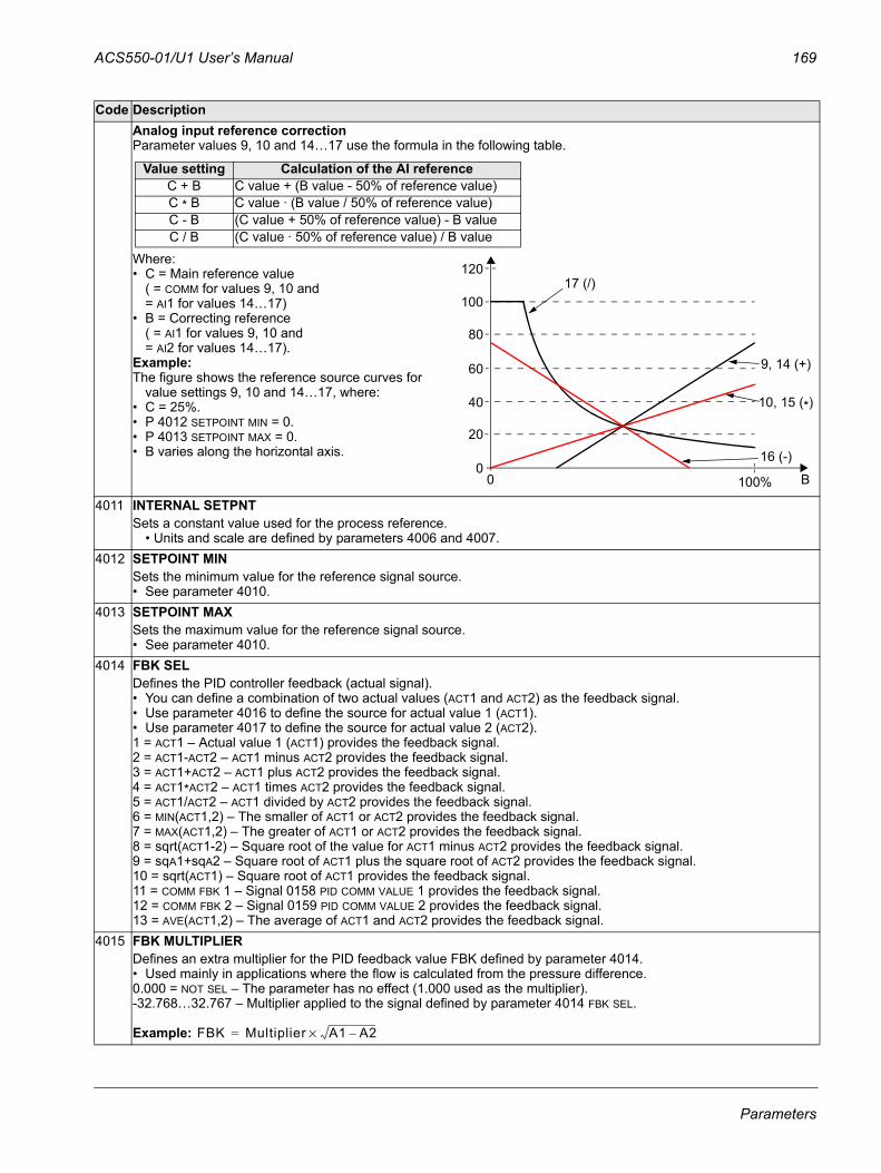
ACS550-01/U1 User’s Manual 169
Analog input reference correctionParameter values 9, 10 and 14…17 use the formula in the following table.
Where:• C = Main reference value
( = COMM for values 9, 10 and = AI1 for values 14…17)
• B = Correcting reference ( = AI1 for values 9, 10 and = AI2 for values 14…17).
Example:The figure shows the reference source curves for
value settings 9, 10 and 14…17, where:• C = 25%.• P 4012 SETPOINT MIN = 0.• P 4013 SETPOINT MAX = 0.• B varies along the horizontal axis.
4011 INTERNAL SETPNTSets a constant value used for the process reference.
• Units and scale are defined by parameters 4006 and 4007.4012 SETPOINT MIN
Sets the minimum value for the reference signal source. • See parameter 4010.
4013 SETPOINT MAXSets the maximum value for the reference signal source. • See parameter 4010.
4014 FBK SELDefines the PID controller feedback (actual signal). • You can define a combination of two actual values (ACT1 and ACT2) as the feedback signal. • Use parameter 4016 to define the source for actual value 1 (ACT1).• Use parameter 4017 to define the source for actual value 2 (ACT2).1 = ACT1 – Actual value 1 (ACT1) provides the feedback signal.2 = ACT1-ACT2 – ACT1 minus ACT2 provides the feedback signal.3 = ACT1+ACT2 – ACT1 plus ACT2 provides the feedback signal.4 = ACT1*ACT2 – ACT1 times ACT2 provides the feedback signal.5 = ACT1/ACT2 – ACT1 divided by ACT2 provides the feedback signal.6 = MIN(ACT1,2) – The smaller of ACT1 or ACT2 provides the feedback signal.7 = MAX(ACT1,2) – The greater of ACT1 or ACT2 provides the feedback signal.8 = sqrt(ACT1-2) – Square root of the value for ACT1 minus ACT2 provides the feedback signal.9 = sqA1+sqA2 – Square root of ACT1 plus the square root of ACT2 provides the feedback signal.10 = sqrt(ACT1) – Square root of ACT1 provides the feedback signal.11 = COMM FBK 1 – Signal 0158 PID COMM VALUE 1 provides the feedback signal.12 = COMM FBK 2 – Signal 0159 PID COMM VALUE 2 provides the feedback signal.13 = AVE(ACT1,2) – The average of ACT1 and ACT2 provides the feedback signal.
4015 FBK MULTIPLIERDefines an extra multiplier for the PID feedback value FBK defined by parameter 4014. • Used mainly in applications where the flow is calculated from the pressure difference.0.000 = NOT SEL – The parameter has no effect (1.000 used as the multiplier). -32.768…32.767 – Multiplier applied to the signal defined by parameter 4014 FBK SEL.
Example:
Code Description
Value setting Calculation of the AI referenceC + B C value + (B value - 50% of reference value)C * B C value · (B value / 50% of reference value)C - B (C value + 50% of reference value) - B valueC / B (C value · 50% of reference value) / B value
120
100
80
60
40
20
00 100%
9, 14 (+)
16 (-)
10, 15 (*)
17 (/)
B
FBK Multiplier A1 A2–×=
Parameters
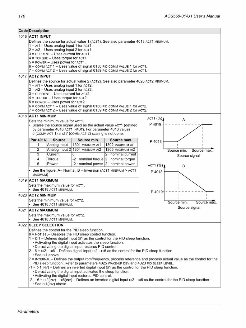
170 ACS550-01/U1 User’s Manual
4016 ACT1 INPUT Defines the source for actual value 1 (ACT1). See also parameter 4018 ACT1 MINIMUM.1 = AI1 – Uses analog input 1 for ACT1.2 = AI2 – Uses analog input 2 for ACT1.3 = CURRENT – Uses current for ACT1.4 = TORQUE – Uses torque for ACT1.5 = POWER – Uses power for ACT1.6 = COMM ACT 1 – Uses value of signal 0158 PID COMM VALUE 1 for ACT1.7 = COMM ACT 2 – Uses value of signal 0159 PID COMM VALUE 2 for ACT1.
4017 ACT2 INPUTDefines the source for actual value 2 (ACT2). See also parameter 4020 ACT2 MINIMUM.1 = AI1 – Uses analog input 1 for ACT2.2 = AI2 – Uses analog input 2 for ACT2.3 = CURRENT – Uses current for ACT2.4 = TORQUE – Uses torque for ACT2.5 = POWER – Uses power for ACT2.6 = COMM ACT 1 – Uses value of signal 0158 PID COMM VALUE 1 for ACT2.7 = COMM ACT 2 – Uses value of signal 0159 PID COMM VALUE 2 for ACT2.
4018 ACT1 MINIMUMSets the minimum value for ACT1.• Scales the source signal used as the actual value ACT1 (defined
by parameter 4016 ACT1 INPUT). For parameter 4016 values 6 (COMM ACT 1) and 7 (COMM ACT 2) scaling is not done.
• See the figure: A= Normal; B = Inversion (ACT1 MINIMUM > ACT1 MAXIMUM)
4019 ACT1 MAXIMUMSets the maximum value for ACT1. • See 4018 ACT1 MINIMUM.
4020 ACT2 MINIMUMSets the minimum value for ACT2. • See 4018 ACT1 MINIMUM.
4021 ACT2 MAXIMUMSets the maximum value for ACT2. • See 4018 ACT1 MINIMUM.
4022 SLEEP SELECTIONDefines the control for the PID sleep function.0 = NOT SEL– Disables the PID sleep control function.1 = DI1 – Defines digital input DI1 as the control for the PID sleep function.
• Activating the digital input activates the sleep function.• De-activating the digital input restores PID control.
2…6 = DI2…DI6 – Defines digital input DI2…DI6 as the control for the PID sleep function.• See DI1 above.
7 = INTERNAL – Defines the output rpm/frequency, process reference and process actual value as the control for the PID sleep function. Refer to parameters 4025 WAKE-UP DEV and 4023 PID SLEEP LEVEL.
-1 = DI1(INV) – Defines an inverted digital input DI1 as the control for the PID sleep function.• De-activating the digital input activates the sleep function.• Activating the digital input restores PID control.
-2…-6 = DI2(INV)…DI6(INV) – Defines an inverted digital input DI2…DI6 as the control for the PID sleep function.• See DI1(INV) above.
Code Description
Par 4016 Source Source min. Source max.1 Analog input 1 1301 MINIMUM AI1 1302 MAXIMUM AI12 Analog input 2 1304 MINIMUM AI2 1305 MAXIMUM AI23 Current 0 2 · nominal current4 Torque -2 · nominal torque 2 · nominal torque5 Power -2 · nominal power 2 · nominal power
P 4019
P 4018
ACT1 (%) A
B
Source signalSource min. Source max.
P 4018
P 4019
ACT1 (%)
Source signalSource min. Source max.
Parameters
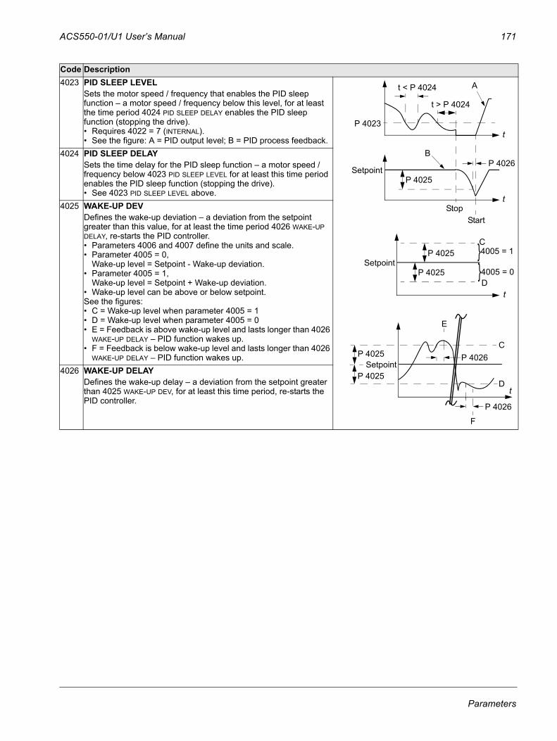
ACS550-01/U1 User’s Manual 171
4023 PID SLEEP LEVELSets the motor speed / frequency that enables the PID sleep function – a motor speed / frequency below this level, for at least the time period 4024 PID SLEEP DELAY enables the PID sleep function (stopping the drive). • Requires 4022 = 7 (INTERNAL).• See the figure: A = PID output level; B = PID process feedback.
4024 PID SLEEP DELAYSets the time delay for the PID sleep function – a motor speed / frequency below 4023 PID SLEEP LEVEL for at least this time period enables the PID sleep function (stopping the drive). • See 4023 PID SLEEP LEVEL above.
4025 WAKE-UP DEVDefines the wake-up deviation – a deviation from the setpoint greater than this value, for at least the time period 4026 WAKE-UP DELAY, re-starts the PID controller. • Parameters 4006 and 4007 define the units and scale.• Parameter 4005 = 0,
Wake-up level = Setpoint - Wake-up deviation.• Parameter 4005 = 1,
Wake-up level = Setpoint + Wake-up deviation.• Wake-up level can be above or below setpoint. See the figures: • C = Wake-up level when parameter 4005 = 1• D = Wake-up level when parameter 4005 = 0• E = Feedback is above wake-up level and lasts longer than 4026
WAKE-UP DELAY – PID function wakes up.• F = Feedback is below wake-up level and lasts longer than 4026
WAKE-UP DELAY – PID function wakes up.4026 WAKE-UP DELAY
Defines the wake-up delay – a deviation from the setpoint greater than 4025 WAKE-UP DEV, for at least this time period, re-starts the PID controller.
Code Description
Start
t < P 4024
t > P 4024
Stop
P 4023
P 4025
P 4026Setpoint
A
B
t
t
P 4025Setpoint
P 4025C
D
}}4005 = 1
4005 = 0
t
P 4025Setpoint
P 4025C
D
P 4026
E
F
P 4026
t
Parameters
172 ACS550-01/U1 User’s Manual
4027 PID 1 PARAM SETProcess PID (PID1) has two separate sets of parameters, PID set 1 and PID set 2.
• PID set 1 uses parameters 4001…4026.• PID set 2 uses parameters 4101…4126.
PID 1 PARAM SET defines which set is selected.0 = SET 1 – PID Set 1 (parameters 4001…4026) is active.1 = DI1 – Defines digital input DI1 as the control for PID Set selection.
• Activating the digital input selects PID Set 2.• De-activating the digital input selects PID Set 1.
2…6 = DI2…DI6 – Defines digital input DI2…DI6 as the control for PID Set selection.• See DI1 above.
7 = SET 2 – PID Set 2 (parameters 4101…4126) is active.8…11 = TIMED FUNC 1…4 – Defines the Timed function as the control for the PID Set selection (Timed function de-
activated = PID Set 1; Timed function activated = PID Set 2)• See Group 36: TIMED FUNCTIONS.
12 = 2-ZONE MIN – The drive calculates the difference between setpoint 1 and feedback 1 as well as setpoint 2 and feedback 2. The drive will control the zone (and select the set) that has a larger difference. • A positive difference (a setpoint higher than the feedback) is always larger than a negative difference. This keeps
feedback values at or above the setpoint.• Controller does not react to the situation of feedback above setpoint if another zone's feedback is closer to its
setpoint.13 = 2-ZONE MAX – The drive calculates the difference between setpoint 1 and feedback 1 as well as setpoint 2 and
feedback 2. The drive will control the zone (and select the set) that has a smaller difference. • A negative difference (a setpoint lower than the feedback) is always smaller than a positive difference. This keeps
feedback values at or below the setpoint.• Controller does not react to the situation of feedback below setpoint if another zone's feedback is closer to its
setpoint.14 = 2-ZONE AVE – The drive calculates the difference between setpoint 1 and feedback 1 as well as setpoint 2 and
feedback 2. In addition, it calculates the average of the deviations and uses it to control zone 1. Therefore one feedback is kept above its setpoint and another is kept as much below its setpoint.
-1 = DI1(INV) – Defines an inverted digital input DI1 as the control for PID Set selection.• Activating the digital input selects PID Set 1.• De-activating the digital input selects PID Set 2.
-2…-6 = DI2(INV)…DI6(INV) – Defines an inverted digital input DI2…DI6 as the control for PID Set selection.• See DI1(INV) above.
Code Description
Parameters

ACS550-01/U1 User’s Manual 173
Group 41: PROCESS PID SET 2Parameters of this group belong to PID parameter set 2. The operation of parameters 4101…4126 is analogous with set 1 parameters 4001…4026.
PID parameter set 2 can be selected by parameter 4027 PID 1 PARAM SET.
Code Description 4101 … 4126
See 4001 …4026
Parameters
174 ACS550-01/U1 User’s Manual
Group 42: EXT / TRIM PIDThis group defines the parameters used for the second PID controller (PID2), which is used for the External / Trimming PID.
The operation of parameters 4201…4221 is analogous with Process PID set 1 (PID1) parameters 4001…4021.
Code Description4201 … 4221
See 4001 …4021
4228 ACTIVATEDefines the source for enabling the external PID function.
• Requires 4230 TRIM MODE = 0 (NOT SEL).0 = NOT SEL – Disables external PID control.1 = DI1 – Defines digital input DI1 as the control for enabling external PID control.
• Activating the digital input enables external PID control.• De-activating the digital input disables external PID control.
2…6 = DI2…DI6 – Defines digital input DI2…DI6 as the control for enabling external PID control.• See DI1 above.
7 = DRIVE RUN – Defines the start command as the control for enabling external PID control.• Activating the start command (drive is running) enables external PID control.
8 = ON – Defines the power-on as the control for enabling external PID control.• Activating power to the drive enables external PID control.
9…12 = TIMED FUNC 1…4 – Defines the Timed function as the control for enabling external PID control (Timed function active enables external PID control).• See Group 36: TIMED FUNCTIONS.
-1 = DI1(INV) – Defines an inverted digital input DI1 as the control for enabling external PID control.• Activating the digital input disables external PID control.• De-activating the digital input enables external PID control.
-2…-6 = DI2(INV)…DI6(INV) – Defines an inverted digital input DI2…DI6 as the control for enabling external PID control.• See DI1(INV) above.
4229 OFFSETDefines the offset for the PID output.• When PID is activated, output starts from this value.• When PID is deactivated, output resets to this value.• Parameter is active when 4230 TRIM MODE = 0 (trim mode is not active).
4230 TRIM MODESelects the type of trim, if any. Using the trim it is possible to combine a corrective factor to the drive reference.0 = NOT SEL – Disables the trim function.1 = PROPORTIONAL – Adds a trim factor that is proportional to the rpm/Hz reference.2 = DIRECT – Adds a trim factor based on the control loop’s maximum limit.
4231 TRIM SCALEDefines the multiplier (as a percent, plus or minus) used in the trim mode.
Parameters
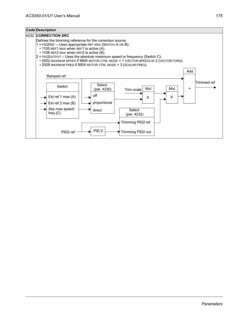
ACS550-01/U1 User’s Manual 175
4232 CORRECTION SRCDefines the trimming reference for the correction source.1 = PID2REF – Uses appropriate REF MAX (SWITCH A OR B):
• 1105 REF1 MAX when REF1 is active (A).• 1108 REF2 MAX when REF2 is active (B).
2 = PID2OUTPUT – Uses the absolute maximum speed or frequency (Switch C):• 2002 MAXIMUM SPEED if 9904 MOTOR CTRL MODE = 1 (VECTOR:sPEED) or 2 (VECTOR:TORQ).• 2008 MAXIMUM FREQ if 9904 MOTOR CTRL MODE = 3 (SCALAR:FREQ).
Code Description
Switch Mul. Mul. +
Select
Add
XX
(par. 4232)
Trimmed ref
PID2 ref
Select (par. 4230)
Ext ref 1 max (A)
Ext ref 2 max (B)Abs max speed/
Ramped ref
off
proportional
direct
Trim scale
PID 2 Trimming PID2 out
Trimming PID2 ref
freq (C)
Parameters
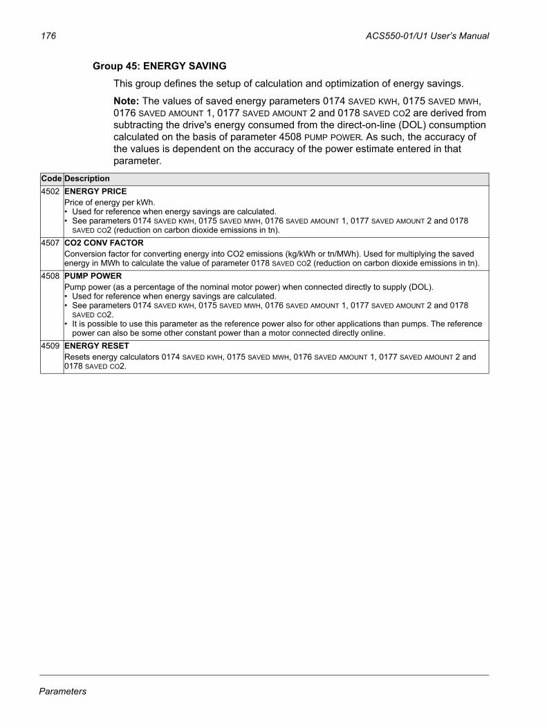
176 ACS550-01/U1 User’s Manual
Group 45: ENERGY SAVINGThis group defines the setup of calculation and optimization of energy savings.
Note: The values of saved energy parameters 0174 SAVED KWH, 0175 SAVED MWH, 0176 SAVED AMOUNT 1, 0177 SAVED AMOUNT 2 and 0178 SAVED CO2 are derived from subtracting the drive's energy consumed from the direct-on-line (DOL) consumption calculated on the basis of parameter 4508 PUMP POWER. As such, the accuracy of the values is dependent on the accuracy of the power estimate entered in that parameter.
Code Description4502 ENERGY PRICE
Price of energy per kWh. • Used for reference when energy savings are calculated. • See parameters 0174 SAVED KWH, 0175 SAVED MWH, 0176 SAVED AMOUNT 1, 0177 SAVED AMOUNT 2 and 0178
SAVED CO2 (reduction on carbon dioxide emissions in tn).4507 CO2 CONV FACTOR
Conversion factor for converting energy into CO2 emissions (kg/kWh or tn/MWh). Used for multiplying the saved energy in MWh to calculate the value of parameter 0178 SAVED CO2 (reduction on carbon dioxide emissions in tn).
4508 PUMP POWERPump power (as a percentage of the nominal motor power) when connected directly to supply (DOL). • Used for reference when energy savings are calculated. • See parameters 0174 SAVED KWH, 0175 SAVED MWH, 0176 SAVED AMOUNT 1, 0177 SAVED AMOUNT 2 and 0178
SAVED CO2.• It is possible to use this parameter as the reference power also for other applications than pumps. The reference
power can also be some other constant power than a motor connected directly online.4509 ENERGY RESET
Resets energy calculators 0174 SAVED KWH, 0175 SAVED MWH, 0176 SAVED AMOUNT 1, 0177 SAVED AMOUNT 2 and 0178 SAVED CO2.
Parameters
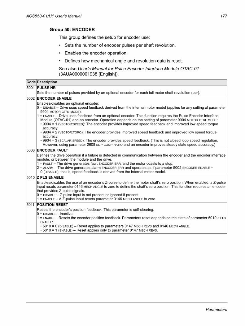
ACS550-01/U1 User’s Manual 177
Group 50: ENCODERThis group defines the setup for encoder use:
• Sets the number of encoder pulses per shaft revolution.
• Enables the encoder operation.
• Defines how mechanical angle and revolution data is reset.
See also User’s Manual for Pulse Encoder Interface Module OTAC-01 (3AUA0000001938 [English]).
Code Description5001 PULSE NR
Sets the number of pulses provided by an optional encoder for each full motor shaft revolution (ppr).5002 ENCODER ENABLE
Enables/disables an optional encoder.0 = DISABLE – Drive uses speed feedback derived from the internal motor model (applies for any setting of parameter
9904 MOTOR CTRL MODE).1 = ENABLE – Drive uses feedback from an optional encoder. This function requires the Pulse Encoder Interface
Module (OTAC-01) and an encoder. Operation depends on the setting of parameter 9904 MOTOR CTRL MODE:• 9904 = 1 (VECTOR:SPEED): The encoder provides improved speed feedback and improved low speed torque
accuracy. • 9904 = 2 (VECTOR:TORQ): The encoder provides improved speed feedback and improved low speed torque
accuracy. • 9904 = 3 (SCALAR:SPEED): The encoder provides speed feedback. (This is not closed loop speed regulation.
However, using parameter 2608 SLIP COMP RATIO and an encoder improves steady state speed accuracy.)5003 ENCODER FAULT
Defines the drive operation if a failure is detected in communication between the encoder and the encoder interface module, or between the module and the drive.1 = FAULT – The drive generates fault ENCODER ERR, and the motor coasts to a stop. 2 = ALARM – The drive generates alarm ENCODER ERR and operates as if parameter 5002 ENCODER ENABLE =
0 (DISABLE), that is, speed feedback is derived from the internal motor model.5010 Z PLS ENABLE
Enables/disables the use of an encoder’s Z-pulse to define the motor shaft’s zero position. When enabled, a Z-pulse input resets parameter 0146 MECH ANGLE to zero to define the shaft’s zero position. This function requires an encoder that provides Z-pulse signals.0 = DISABLE – Z-pulse input is not present or ignored if present.1 = ENABLE – A Z-pulse input resets parameter 0146 MECH ANGLE to zero.
5011 POSITION RESETResets the encoder’s position feedback. This parameter is self-clearing.0 = DISABLE – Inactive.1 = ENABLE – Resets the encoder position feedback. Parameters reset depends on the state of parameter 5010 Z PLS
ENABLE:• 5010 = 0 (DISABLE) – Reset applies to parameters 0147 MECH REVS and 0146 MECH ANGLE.• 5010 = 1 (ENABLE) – Reset applies only to parameter 0147 MECH REVS.
Parameters
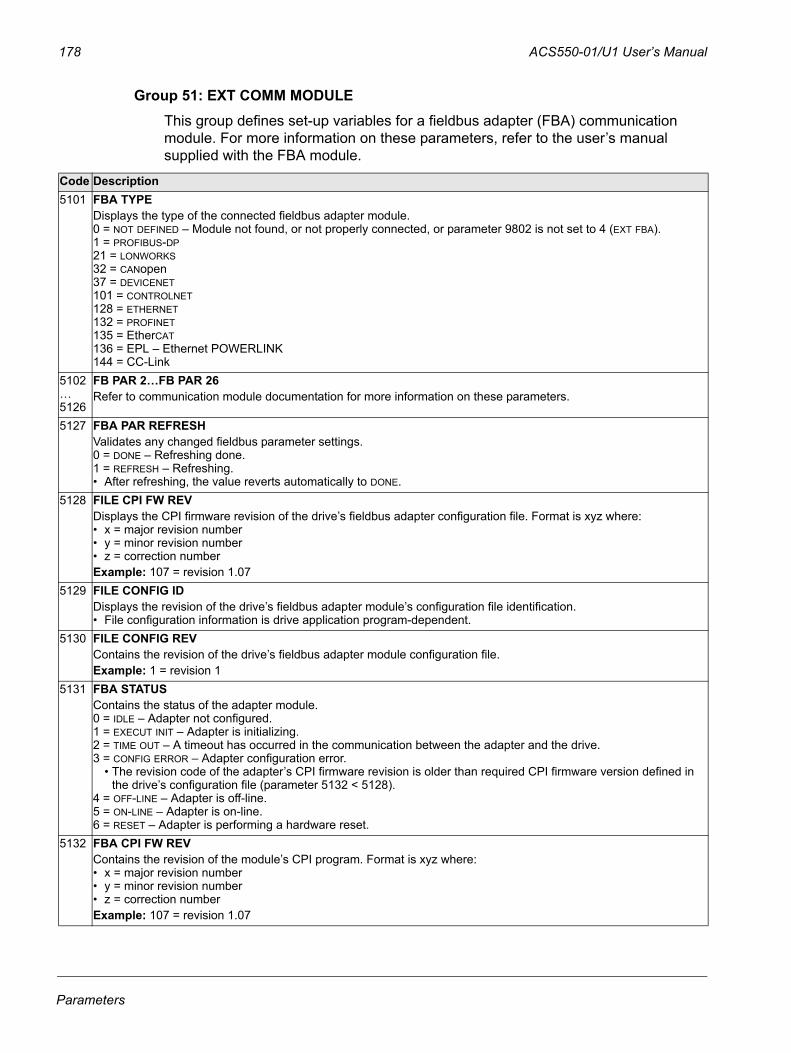
178 ACS550-01/U1 User’s Manual
Group 51: EXT COMM MODULEThis group defines set-up variables for a fieldbus adapter (FBA) communication module. For more information on these parameters, refer to the user’s manual supplied with the FBA module.
Code Description5101 FBA TYPE
Displays the type of the connected fieldbus adapter module.0 = NOT DEFINED – Module not found, or not properly connected, or parameter 9802 is not set to 4 (EXT FBA).1 = PROFIBUS-DP21 = LONWORKS32 = CANopen37 = DEVICENET101 = CONTROLNET128 = ETHERNET132 = PROFINET135 = EtherCAT136 = EPL – Ethernet POWERLINK144 = CC-Link
5102… 5126
FB PAR 2…FB PAR 26Refer to communication module documentation for more information on these parameters.
5127 FBA PAR REFRESHValidates any changed fieldbus parameter settings. 0 = DONE – Refreshing done.1 = REFRESH – Refreshing.• After refreshing, the value reverts automatically to DONE.
5128 FILE CPI FW REVDisplays the CPI firmware revision of the drive’s fieldbus adapter configuration file. Format is xyz where:• x = major revision number• y = minor revision number• z = correction numberExample: 107 = revision 1.07
5129 FILE CONFIG IDDisplays the revision of the drive’s fieldbus adapter module’s configuration file identification. • File configuration information is drive application program-dependent.
5130 FILE CONFIG REVContains the revision of the drive’s fieldbus adapter module configuration file. Example: 1 = revision 1
5131 FBA STATUSContains the status of the adapter module. 0 = IDLE – Adapter not configured.1 = EXECUT INIT – Adapter is initializing. 2 = TIME OUT – A timeout has occurred in the communication between the adapter and the drive.3 = CONFIG ERROR – Adapter configuration error.
• The revision code of the adapter’s CPI firmware revision is older than required CPI firmware version defined in the drive’s configuration file (parameter 5132 < 5128).
4 = OFF-LINE – Adapter is off-line.5 = ON-LINE – Adapter is on-line.6 = RESET – Adapter is performing a hardware reset.
5132 FBA CPI FW REVContains the revision of the module’s CPI program. Format is xyz where:• x = major revision number• y = minor revision number• z = correction numberExample: 107 = revision 1.07
Parameters

ACS550-01/U1 User’s Manual 179
5133 FBA APPL FW REVContains the revision of the module’s application program. Format is xyz (see parameter 5132).
Code Description
Parameters
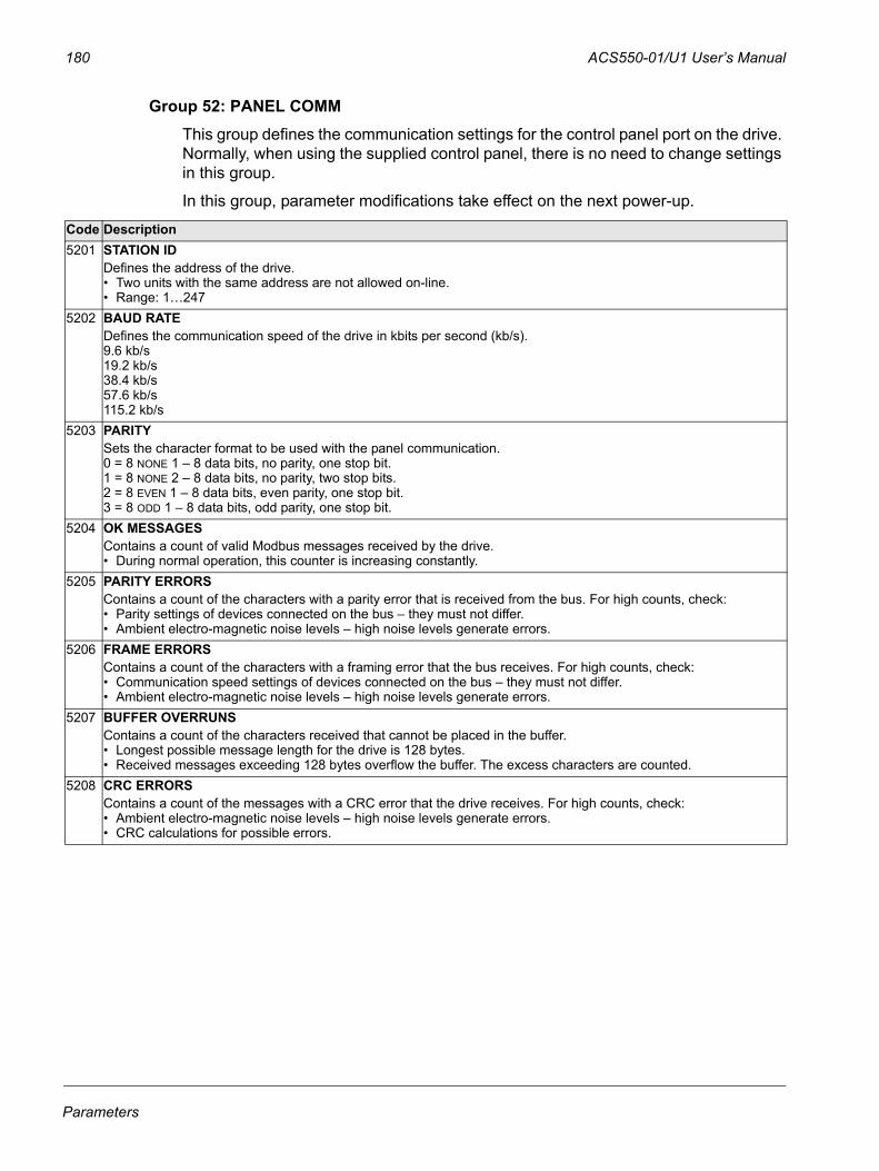
180 ACS550-01/U1 User’s Manual
Group 52: PANEL COMMThis group defines the communication settings for the control panel port on the drive. Normally, when using the supplied control panel, there is no need to change settings in this group.
In this group, parameter modifications take effect on the next power-up.
Code Description5201 STATION ID
Defines the address of the drive. • Two units with the same address are not allowed on-line.• Range: 1…247
5202 BAUD RATEDefines the communication speed of the drive in kbits per second (kb/s).9.6 kb/s19.2 kb/s38.4 kb/s57.6 kb/s115.2 kb/s
5203 PARITYSets the character format to be used with the panel communication.0 = 8 NONE 1 – 8 data bits, no parity, one stop bit.1 = 8 NONE 2 – 8 data bits, no parity, two stop bits.2 = 8 EVEN 1 – 8 data bits, even parity, one stop bit.3 = 8 ODD 1 – 8 data bits, odd parity, one stop bit.
5204 OK MESSAGESContains a count of valid Modbus messages received by the drive.• During normal operation, this counter is increasing constantly.
5205 PARITY ERRORSContains a count of the characters with a parity error that is received from the bus. For high counts, check:• Parity settings of devices connected on the bus – they must not differ.• Ambient electro-magnetic noise levels – high noise levels generate errors.
5206 FRAME ERRORSContains a count of the characters with a framing error that the bus receives. For high counts, check:• Communication speed settings of devices connected on the bus – they must not differ.• Ambient electro-magnetic noise levels – high noise levels generate errors.
5207 BUFFER OVERRUNSContains a count of the characters received that cannot be placed in the buffer.• Longest possible message length for the drive is 128 bytes.• Received messages exceeding 128 bytes overflow the buffer. The excess characters are counted.
5208 CRC ERRORSContains a count of the messages with a CRC error that the drive receives. For high counts, check:• Ambient electro-magnetic noise levels – high noise levels generate errors.• CRC calculations for possible errors.
Parameters
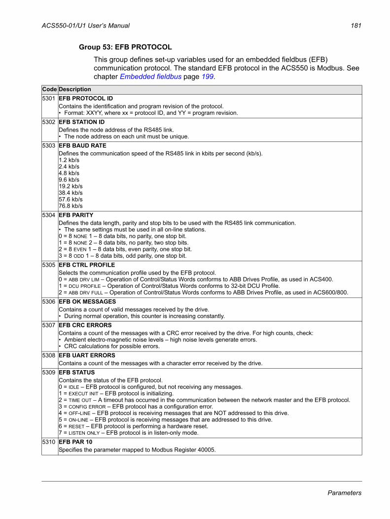
ACS550-01/U1 User’s Manual 181
Group 53: EFB PROTOCOLThis group defines set-up variables used for an embedded fieldbus (EFB) communication protocol. The standard EFB protocol in the ACS550 is Modbus. See chapter Embedded fieldbus page 199.
Code Description5301 EFB PROTOCOL ID
Contains the identification and program revision of the protocol. • Format: XXYY, where xx = protocol ID, and YY = program revision.
5302 EFB STATION IDDefines the node address of the RS485 link. • The node address on each unit must be unique.
5303 EFB BAUD RATEDefines the communication speed of the RS485 link in kbits per second (kb/s).1.2 kb/s2.4 kb/s4.8 kb/s9.6 kb/s19.2 kb/s38.4 kb/s57.6 kb/s76.8 kb/s
5304 EFB PARITYDefines the data length, parity and stop bits to be used with the RS485 link communication. • The same settings must be used in all on-line stations.0 = 8 NONE 1 – 8 data bits, no parity, one stop bit.1 = 8 NONE 2 – 8 data bits, no parity, two stop bits.2 = 8 EVEN 1 – 8 data bits, even parity, one stop bit.3 = 8 ODD 1 – 8 data bits, odd parity, one stop bit.
5305 EFB CTRL PROFILESelects the communication profile used by the EFB protocol.0 = ABB DRV LIM – Operation of Control/Status Words conforms to ABB Drives Profile, as used in ACS400.1 = DCU PROFILE – Operation of Control/Status Words conforms to 32-bit DCU Profile.2 = ABB DRV FULL – Operation of Control/Status Words conforms to ABB Drives Profile, as used in ACS600/800.
5306 EFB OK MESSAGESContains a count of valid messages received by the drive.• During normal operation, this counter is increasing constantly.
5307 EFB CRC ERRORSContains a count of the messages with a CRC error received by the drive. For high counts, check:• Ambient electro-magnetic noise levels – high noise levels generate errors.• CRC calculations for possible errors.
5308 EFB UART ERRORSContains a count of the messages with a character error received by the drive.
5309 EFB STATUSContains the status of the EFB protocol. 0 = IDLE – EFB protocol is configured, but not receiving any messages.1 = EXECUT INIT – EFB protocol is initializing.2 = TIME OUT – A timeout has occurred in the communication between the network master and the EFB protocol.3 = CONFIG ERROR – EFB protocol has a configuration error. 4 = OFF-LINE – EFB protocol is receiving messages that are NOT addressed to this drive.5 = ON-LINE – EFB protocol is receiving messages that are addressed to this drive.6 = RESET – EFB protocol is performing a hardware reset.7 = LISTEN ONLY – EFB protocol is in listen-only mode.
5310 EFB PAR 10Specifies the parameter mapped to Modbus Register 40005.
Parameters
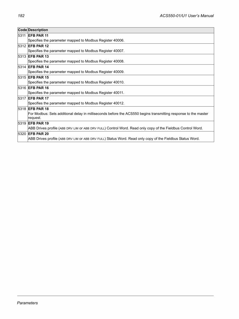
182 ACS550-01/U1 User’s Manual
5311 EFB PAR 11Specifies the parameter mapped to Modbus Register 40006.
5312 EFB PAR 12Specifies the parameter mapped to Modbus Register 40007.
5313 EFB PAR 13Specifies the parameter mapped to Modbus Register 40008.
5314 EFB PAR 14Specifies the parameter mapped to Modbus Register 40009.
5315 EFB PAR 15Specifies the parameter mapped to Modbus Register 40010.
5316 EFB PAR 16Specifies the parameter mapped to Modbus Register 40011.
5317 EFB PAR 17Specifies the parameter mapped to Modbus Register 40012.
5318 EFB PAR 18For Modbus: Sets additional delay in milliseconds before the ACS550 begins transmitting response to the master request.
5319 EFB PAR 19ABB Drives profile (ABB DRV LIM or ABB DRV FULL) Control Word. Read only copy of the Fieldbus Control Word.
5320 EFB PAR 20ABB Drives profile (ABB DRV LIM or ABB DRV FULL) Status Word. Read only copy of the Fieldbus Status Word.
Code Description
Parameters
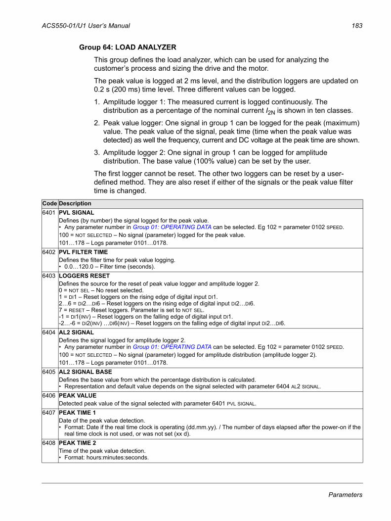
ACS550-01/U1 User’s Manual 183
Group 64: LOAD ANALYZERThis group defines the load analyzer, which can be used for analyzing the customer’s process and sizing the drive and the motor.
The peak value is logged at 2 ms level, and the distribution loggers are updated on 0.2 s (200 ms) time level. Three different values can be logged.
1. Amplitude logger 1: The measured current is logged continuously. The distribution as a percentage of the nominal current I2N is shown in ten classes.
2. Peak value logger: One signal in group 1 can be logged for the peak (maximum) value. The peak value of the signal, peak time (time when the peak value was detected) as well the frequency, current and DC voltage at the peak time are shown.
3. Amplitude logger 2: One signal in group 1 can be logged for amplitude distribution. The base value (100% value) can be set by the user.
The first logger cannot be reset. The other two loggers can be reset by a user-defined method. They are also reset if either of the signals or the peak value filter time is changed.
Code Description6401 PVL SIGNAL
Defines (by number) the signal logged for the peak value.• Any parameter number in Group 01: OPERATING DATA can be selected. Eg 102 = parameter 0102 SPEED.100 = NOT SELECTED – No signal (parameter) logged for the peak value.101…178 – Logs parameter 0101…0178.
6402 PVL FILTER TIMEDefines the filter time for peak value logging.• 0.0…120.0 – Filter time (seconds).
6403 LOGGERS RESETDefines the source for the reset of peak value logger and amplitude logger 2. 0 = NOT SEL – No reset selected.1 = DI1 – Reset loggers on the rising edge of digital input DI1.2…6 = DI2…DI6 – Reset loggers on the rising edge of digital input DI2…DI6.7 = RESET – Reset loggers. Parameter is set to NOT SEL. -1 = DI1(INV) – Reset loggers on the falling edge of digital input DI1.-2…-6 = DI2(INV) …DI6(INV) – Reset loggers on the falling edge of digital input DI2…DI6.
6404 AL2 SIGNALDefines the signal logged for amplitude logger 2.• Any parameter number in Group 01: OPERATING DATA can be selected. Eg 102 = parameter 0102 SPEED.100 = NOT SELECTED – No signal (parameter) logged for amplitude distribution (amplitude logger 2).101…178 – Logs parameter 0101…0178.
6405 AL2 SIGNAL BASEDefines the base value from which the percentage distribution is calculated.• Representation and default value depends on the signal selected with parameter 6404 AL2 SIGNAL.
6406 PEAK VALUEDetected peak value of the signal selected with parameter 6401 PVL SIGNAL.
6407 PEAK TIME 1Date of the peak value detection.• Format: Date if the real time clock is operating (dd.mm.yy). / The number of days elapsed after the power-on if the
real time clock is not used, or was not set (xx d).6408 PEAK TIME 2
Time of the peak value detection.• Format: hours:minutes:seconds.
Parameters
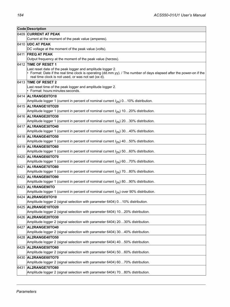
184 ACS550-01/U1 User’s Manual
6409 CURRENT AT PEAKCurrent at the moment of the peak value (amperes).
6410 UDC AT PEAKDC voltage at the moment of the peak value (volts).
6411 FREQ AT PEAKOutput frequency at the moment of the peak value (herzes).
6412 TIME OF RESET 1Last reset date of the peak logger and amplitude logger 2.• Format: Date if the real time clock is operating (dd.mm.yy). / The number of days elapsed after the power-on if the
real time clock is not used, or was not set (xx d).6413 TIME OF RESET 2
Last reset time of the peak logger and amplitude logger 2.• Format: hours:minutes:seconds.
6414 AL1RANGE0TO10Amplitude logger 1 (current in percent of nominal current I2N) 0…10% distribution.
6415 AL1RANGE10TO20Amplitude logger 1 (current in percent of nominal current I2N) 10…20% distribution.
6416 AL1RANGE20TO30Amplitude logger 1 (current in percent of nominal current I2N) 20…30% distribution.
6417 AL1RANGE30TO40Amplitude logger 1 (current in percent of nominal current I2N) 30…40% distribution.
6418 AL1RANGE40TO50Amplitude logger 1 (current in percent of nominal current I2N) 40…50% distribution.
6419 AL1RANGE50TO60Amplitude logger 1 (current in percent of nominal current I2N) 50…60% distribution.
6420 AL1RANGE60TO70Amplitude logger 1 (current in percent of nominal current I2N) 60…70% distribution.
6421 AL1RANGE70TO80Amplitude logger 1 (current in percent of nominal current I2N) 70…80% distribution.
6422 AL1RANGE80TO90Amplitude logger 1 (current in percent of nominal current I2N) 80…90% distribution.
6423 AL1RANGE90TOAmplitude logger 1 (current in percent of nominal current I2N) over 90% distribution.
6424 AL2RANGE0TO10Amplitude logger 2 (signal selection with parameter 6404) 0…10% distribution.
6425 AL2RANGE10TO20Amplitude logger 2 (signal selection with parameter 6404) 10…20% distribution.
6426 AL2RANGE20TO30Amplitude logger 2 (signal selection with parameter 6404) 20…30% distribution.
6427 AL2RANGE30TO40Amplitude logger 2 (signal selection with parameter 6404) 30…40% distribution.
6428 AL2RANGE40TO50Amplitude logger 2 (signal selection with parameter 6404) 40…50% distribution.
6429 AL2RANGE50TO60Amplitude logger 2 (signal selection with parameter 6404) 50…60% distribution.
6430 AL2RANGE60TO70Amplitude logger 2 (signal selection with parameter 6404) 60…70% distribution.
6431 AL2RANGE70TO80Amplitude logger 2 (signal selection with parameter 6404) 70…80% distribution.
Code Description
Parameters

ACS550-01/U1 User’s Manual 185
6432 AL2RANGE80TO90Amplitude logger 2 (signal selection with parameter 6404) 80…90% distribution.
6433 AL2RANGE90TOAmplitude logger 2 (signal selection with parameter 6404) over 90% distribution.
Code Description
Parameters
186 ACS550-01/U1 User’s Manual
Group 81: PFC CONTROLThis group defines a Pump-Fan Control (PFC) mode of operation. The major features of PFC control are:
• The ACS550 controls the motor of pump no. 1, varying the motor speed to control the pump capacity. This motor is the speed regulated motor.
• Direct line connections power the motor of pump no. 2 and pump no.3, etc. The ACS550 switches pump no. 2 (and then pump no. 3, etc.) on and off as needed. These motors are auxiliary motors.
• The ACS550 PID control uses two signals: a process reference and an actual value feedback. The PID controller adjusts the speed (frequency) of the first pump such that the actual value follows the process reference.
• When demand (defined by the process reference) exceeds the first motor’s capacity (user defined as a frequency limit), the PFC control automatically starts an auxiliary pump. The PFC also reduces the speed of the first pump to account for the auxiliary pump’s addition to total output. Then, as before, the PID controller adjusts the speed (frequency) of the first pump such that the actual value follows the process reference. If demand continues to increase, PFC adds additional auxiliary pumps, using the same process.
• When demand drops, such that the first pump speed falls below a minimum limit (user defined by a frequency limit), the PFC control automatically stops an auxiliary pump. The PFC also increases the speed of the first pump to account for the auxiliary pump’s missing output.
• An Interlock function (when enabled) identifies off-line (out of service) motors, and the PFC control skips to the next available motor in the sequence.
• An Autochange function (when enabled and with the appropriate switchgear) equalizes duty time between the pump motors. Autochange periodically increments the position of each motor in the rotation – the speed regulated motor becomes the last auxiliary motor, the first auxiliary motor becomes the speed regulated motor, etc.
Code Description8103 REFERENCE STEP 1
Sets a percentage value that is added to the process reference.• Applies only when at least one auxiliary (constant speed) motor is running. • Default value is 0%.Example: An ACS550 operates three parallel pumps that maintain water pressure in a pipe. • 4011 INTERNAL SETPNT sets a constant pressure reference that controls the pressure in the pipe.• The speed regulated pump operates alone at low water consumption levels.• As water consumption increases, first one constant speed pump operates, then, the second.• As flow increases, the pressure at the output end of the pipe drops relative to the pressure measured at the input
end. As auxiliary motors step in to increase the flow, the adjustments below correct the reference to more closely match the output pressure.
• When the first auxiliary pump operates, increase the reference with parameter 8103 REFERENCE STEP 1.• When two auxiliary pumps operate, increase the reference with parameter 8103 REFERENCE STEP 1 + parameter
8104 REFERENCE STEP 2.• When three auxiliary pumps operate, increase the reference with parameter 8103 REFERENCE STEP 1 + parameter
8104 REFERENCE STEP 2 + parameter 8105 REFERENCE STEP 3.
Parameters
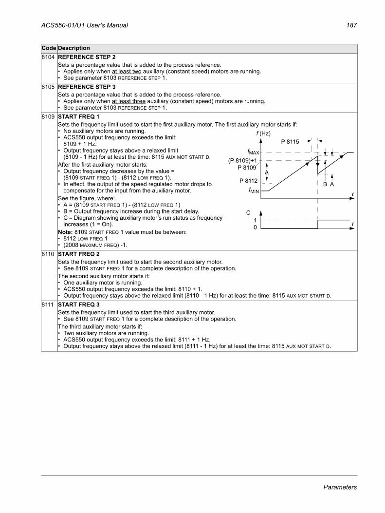
ACS550-01/U1 User’s Manual 187
8104 REFERENCE STEP 2Sets a percentage value that is added to the process reference.• Applies only when at least two auxiliary (constant speed) motors are running. • See parameter 8103 REFERENCE STEP 1.
8105 REFERENCE STEP 3Sets a percentage value that is added to the process reference.• Applies only when at least three auxiliary (constant speed) motors are running. • See parameter 8103 REFERENCE STEP 1.
8109 START FREQ 1Sets the frequency limit used to start the first auxiliary motor. The first auxiliary motor starts if:• No auxiliary motors are running.• ACS550 output frequency exceeds the limit:
8109 + 1 Hz. • Output frequency stays above a relaxed limit
(8109 - 1 Hz) for at least the time: 8115 AUX MOT START D.After the first auxiliary motor starts:• Output frequency decreases by the value =
(8109 START FREQ 1) - (8112 LOW FREQ 1). • In effect, the output of the speed regulated motor drops to
compensate for the input from the auxiliary motor. See the figure, where:• A = (8109 START FREQ 1) - (8112 LOW FREQ 1)• B = Output frequency increase during the start delay.• C = Diagram showing auxiliary motor’s run status as frequency
increases (1 = On).Note: 8109 START FREQ 1 value must be between:• 8112 LOW FREQ 1 • (2008 MAXIMUM FREQ) -1.
8110 START FREQ 2Sets the frequency limit used to start the second auxiliary motor. • See 8109 START FREQ 1 for a complete description of the operation.The second auxiliary motor starts if:• One auxiliary motor is running.• ACS550 output frequency exceeds the limit: 8110 + 1. • Output frequency stays above the relaxed limit (8110 - 1 Hz) for at least the time: 8115 AUX MOT START D.
8111 START FREQ 3Sets the frequency limit used to start the third auxiliary motor. • See 8109 START FREQ 1 for a complete description of the operation.The third auxiliary motor starts if:• Two auxiliary motors are running.• ACS550 output frequency exceeds the limit: 8111 + 1 Hz. • Output frequency stays above the relaxed limit (8111 - 1 Hz) for at least the time: 8115 AUX MOT START D.
Code Description
P 8115
(P 8109)+1
P 8112 AB
10
C
P 8109A
t
t
f (Hz)
fMIN
fMAX
Parameters
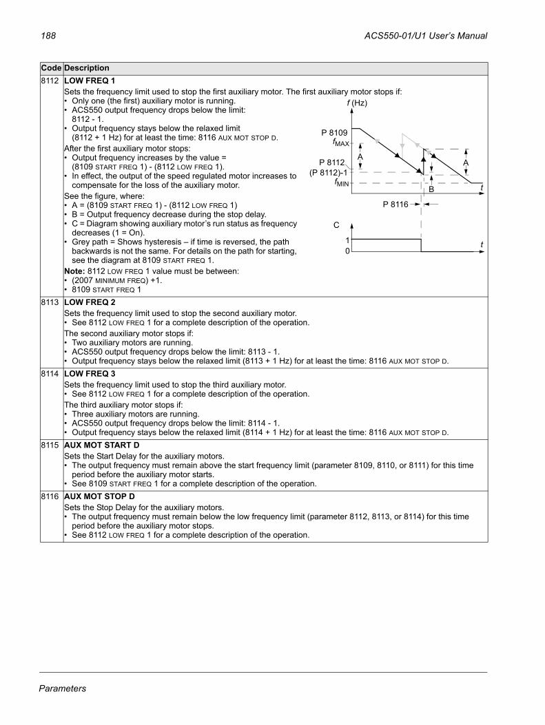
188 ACS550-01/U1 User’s Manual
8112 LOW FREQ 1Sets the frequency limit used to stop the first auxiliary motor. The first auxiliary motor stops if:• Only one (the first) auxiliary motor is running.• ACS550 output frequency drops below the limit:
8112 - 1. • Output frequency stays below the relaxed limit
(8112 + 1 Hz) for at least the time: 8116 AUX MOT STOP D.After the first auxiliary motor stops:• Output frequency increases by the value =
(8109 START FREQ 1) - (8112 LOW FREQ 1). • In effect, the output of the speed regulated motor increases to
compensate for the loss of the auxiliary motor. See the figure, where:• A = (8109 START FREQ 1) - (8112 LOW FREQ 1)• B = Output frequency decrease during the stop delay.• C = Diagram showing auxiliary motor’s run status as frequency
decreases (1 = On).• Grey path = Shows hysteresis – if time is reversed, the path
backwards is not the same. For details on the path for starting, see the diagram at 8109 START FREQ 1.
Note: 8112 LOW FREQ 1 value must be between:• (2007 MINIMUM FREQ) +1.• 8109 START FREQ 1
8113 LOW FREQ 2Sets the frequency limit used to stop the second auxiliary motor. • See 8112 LOW FREQ 1 for a complete description of the operation.The second auxiliary motor stops if:• Two auxiliary motors are running.• ACS550 output frequency drops below the limit: 8113 - 1. • Output frequency stays below the relaxed limit (8113 + 1 Hz) for at least the time: 8116 AUX MOT STOP D.
8114 LOW FREQ 3Sets the frequency limit used to stop the third auxiliary motor. • See 8112 LOW FREQ 1 for a complete description of the operation.The third auxiliary motor stops if:• Three auxiliary motors are running.• ACS550 output frequency drops below the limit: 8114 - 1. • Output frequency stays below the relaxed limit (8114 + 1 Hz) for at least the time: 8116 AUX MOT STOP D.
8115 AUX MOT START DSets the Start Delay for the auxiliary motors. • The output frequency must remain above the start frequency limit (parameter 8109, 8110, or 8111) for this time
period before the auxiliary motor starts.• See 8109 START FREQ 1 for a complete description of the operation.
8116 AUX MOT STOP DSets the Stop Delay for the auxiliary motors. • The output frequency must remain below the low frequency limit (parameter 8112, 8113, or 8114) for this time
period before the auxiliary motor stops.• See 8112 LOW FREQ 1 for a complete description of the operation.
Code Description
t
t
f (Hz)
fMIN
fMAX
P 8116
(P 8112)-1
B
10
C
P 8112
P 8109
AA
Parameters
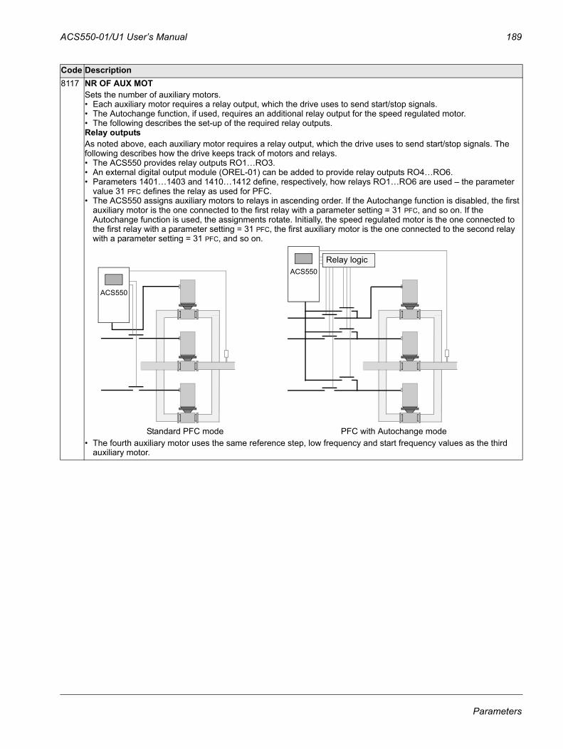
ACS550-01/U1 User’s Manual 189
8117 NR OF AUX MOTSets the number of auxiliary motors.• Each auxiliary motor requires a relay output, which the drive uses to send start/stop signals.• The Autochange function, if used, requires an additional relay output for the speed regulated motor.• The following describes the set-up of the required relay outputs.Relay outputsAs noted above, each auxiliary motor requires a relay output, which the drive uses to send start/stop signals. The following describes how the drive keeps track of motors and relays.• The ACS550 provides relay outputs RO1…RO3. • An external digital output module (OREL-01) can be added to provide relay outputs RO4…RO6.• Parameters 1401…1403 and 1410…1412 define, respectively, how relays RO1…RO6 are used – the parameter
value 31 PFC defines the relay as used for PFC.• The ACS550 assigns auxiliary motors to relays in ascending order. If the Autochange function is disabled, the first
auxiliary motor is the one connected to the first relay with a parameter setting = 31 PFC, and so on. If the Autochange function is used, the assignments rotate. Initially, the speed regulated motor is the one connected to the first relay with a parameter setting = 31 PFC, the first auxiliary motor is the one connected to the second relay with a parameter setting = 31 PFC, and so on.
• The fourth auxiliary motor uses the same reference step, low frequency and start frequency values as the third auxiliary motor.
Code Description
ACS550
Standard PFC mode PFC with Autochange mode
ACS550Relay logic
Parameters
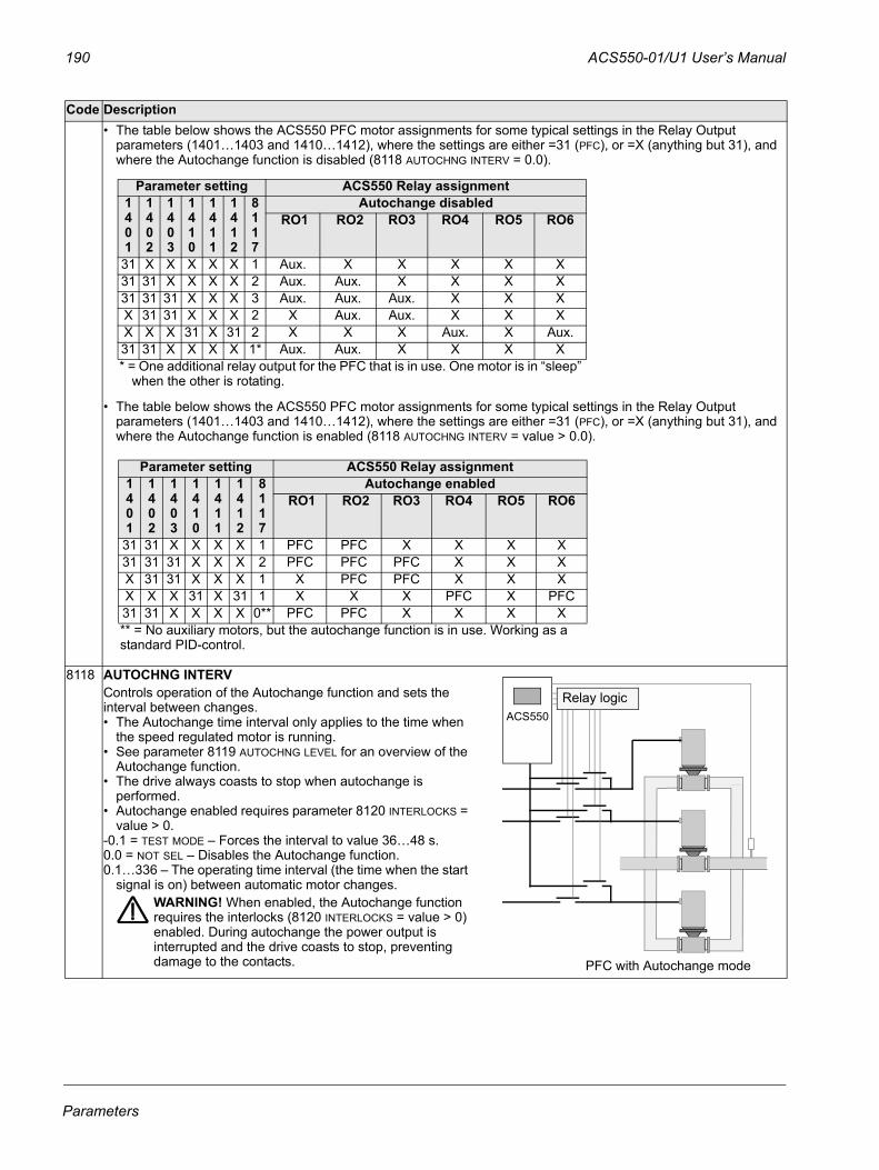
190 ACS550-01/U1 User’s Manual
• The table below shows the ACS550 PFC motor assignments for some typical settings in the Relay Output parameters (1401…1403 and 1410…1412), where the settings are either =31 (PFC), or =X (anything but 31), and where the Autochange function is disabled (8118 AUTOCHNG INTERV = 0.0).
• The table below shows the ACS550 PFC motor assignments for some typical settings in the Relay Output parameters (1401…1403 and 1410…1412), where the settings are either =31 (PFC), or =X (anything but 31), and where the Autochange function is enabled (8118 AUTOCHNG INTERV = value > 0.0).
8118 AUTOCHNG INTERV Controls operation of the Autochange function and sets the interval between changes.• The Autochange time interval only applies to the time when
the speed regulated motor is running. • See parameter 8119 AUTOCHNG LEVEL for an overview of the
Autochange function. • The drive always coasts to stop when autochange is
performed.• Autochange enabled requires parameter 8120 INTERLOCKS =
value > 0.-0.1 = TEST MODE – Forces the interval to value 36…48 s. 0.0 = NOT SEL – Disables the Autochange function.0.1…336 – The operating time interval (the time when the start
signal is on) between automatic motor changes.WARNING! When enabled, the Autochange function requires the interlocks (8120 INTERLOCKS = value > 0) enabled. During autochange the power output is interrupted and the drive coasts to stop, preventing damage to the contacts.
Code Description
Parameter setting ACS550 Relay assignment1401
1402
1403
1410
1411
1412
8117
Autochange disabled RO1 RO2 RO3 RO4 RO5 RO6
31 X X X X X 1 Aux. X X X X X 31 31 X X X X 2 Aux. Aux. X X X X 31 31 31 X X X 3 Aux. Aux. Aux. X X X X 31 31 X X X 2 X Aux. Aux. X X X X X X 31 X 31 2 X X X Aux. X Aux. 31 31 X X X X 1* Aux. Aux. X X X X* = One additional relay output for the PFC that is in use. One motor is in “sleep”
when the other is rotating.
Parameter setting ACS550 Relay assignment1401
1402
1403
1410
1411
1412
8117
Autochange enabled RO1 RO2 RO3 RO4 RO5 RO6
31 31 X X X X 1 PFC PFC X X X X 31 31 31 X X X 2 PFC PFC PFC X X X X 31 31 X X X 1 X PFC PFC X X X X X X 31 X 31 1 X X X PFC X PFC31 31 X X X X 0** PFC PFC X X X X** = No auxiliary motors, but the autochange function is in use. Working as a standard PID-control.
PFC with Autochange mode
ACS550Relay logic
Parameters
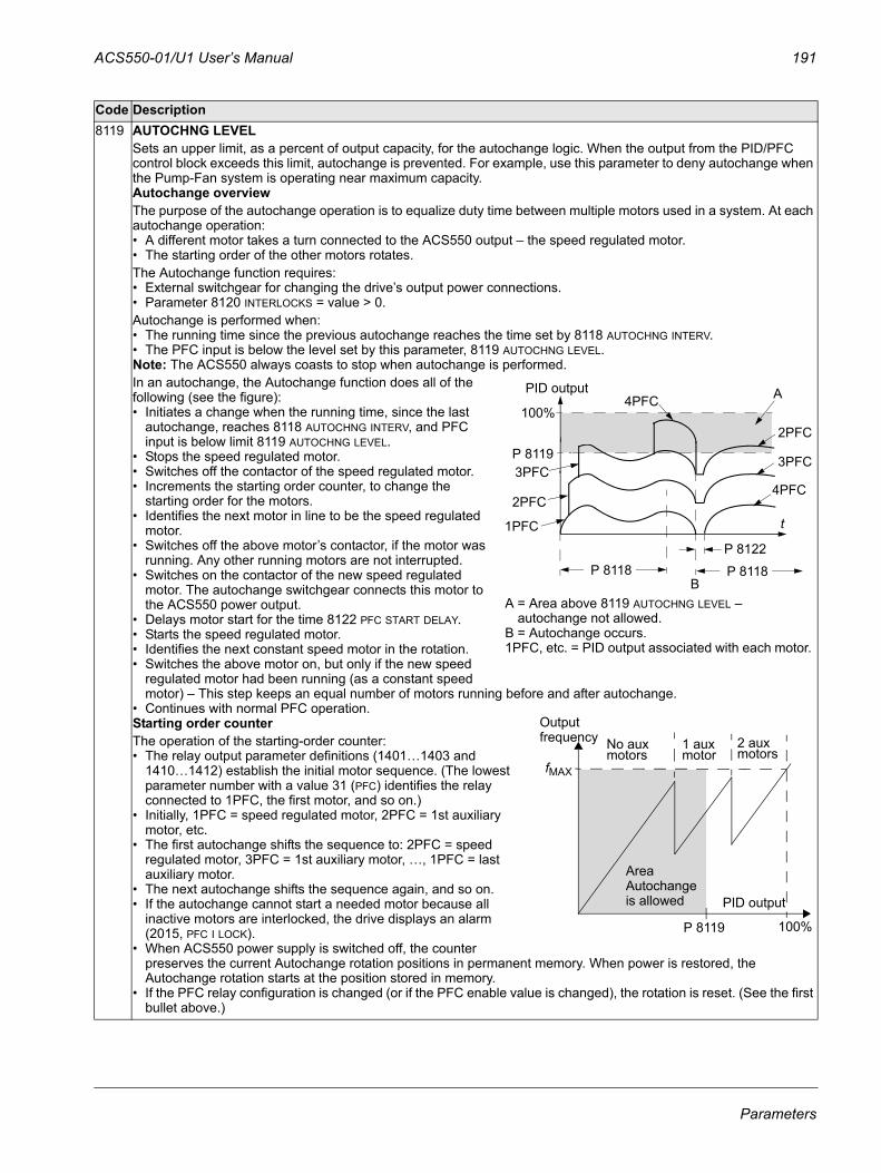
ACS550-01/U1 User’s Manual 191
8119 AUTOCHNG LEVELSets an upper limit, as a percent of output capacity, for the autochange logic. When the output from the PID/PFC control block exceeds this limit, autochange is prevented. For example, use this parameter to deny autochange when the Pump-Fan system is operating near maximum capacity. Autochange overviewThe purpose of the autochange operation is to equalize duty time between multiple motors used in a system. At each autochange operation:• A different motor takes a turn connected to the ACS550 output – the speed regulated motor. • The starting order of the other motors rotates.The Autochange function requires:• External switchgear for changing the drive’s output power connections.• Parameter 8120 INTERLOCKS = value > 0.Autochange is performed when:• The running time since the previous autochange reaches the time set by 8118 AUTOCHNG INTERV.• The PFC input is below the level set by this parameter, 8119 AUTOCHNG LEVEL.Note: The ACS550 always coasts to stop when autochange is performed.In an autochange, the Autochange function does all of the following (see the figure):• Initiates a change when the running time, since the last
autochange, reaches 8118 AUTOCHNG INTERV, and PFC input is below limit 8119 AUTOCHNG LEVEL.
• Stops the speed regulated motor. • Switches off the contactor of the speed regulated motor.• Increments the starting order counter, to change the
starting order for the motors.• Identifies the next motor in line to be the speed regulated
motor.• Switches off the above motor’s contactor, if the motor was
running. Any other running motors are not interrupted.• Switches on the contactor of the new speed regulated
motor. The autochange switchgear connects this motor to the ACS550 power output.
• Delays motor start for the time 8122 PFC START DELAY.• Starts the speed regulated motor. • Identifies the next constant speed motor in the rotation.• Switches the above motor on, but only if the new speed
regulated motor had been running (as a constant speed motor) – This step keeps an equal number of motors running before and after autochange.
• Continues with normal PFC operation.Starting order counterThe operation of the starting-order counter:• The relay output parameter definitions (1401…1403 and
1410…1412) establish the initial motor sequence. (The lowest parameter number with a value 31 (PFC) identifies the relay connected to 1PFC, the first motor, and so on.)
• Initially, 1PFC = speed regulated motor, 2PFC = 1st auxiliary motor, etc.
• The first autochange shifts the sequence to: 2PFC = speed regulated motor, 3PFC = 1st auxiliary motor, …, 1PFC = last auxiliary motor.
• The next autochange shifts the sequence again, and so on.• If the autochange cannot start a needed motor because all
inactive motors are interlocked, the drive displays an alarm (2015, PFC I LOCK).
• When ACS550 power supply is switched off, the counter preserves the current Autochange rotation positions in permanent memory. When power is restored, the Autochange rotation starts at the position stored in memory.
• If the PFC relay configuration is changed (or if the PFC enable value is changed), the rotation is reset. (See the first bullet above.)
Code Description
P 8118B
PID output
P 8119
100%
P 8118
1PFC
2PFC
3PFC
4PFC
4PFC
2PFC
3PFC
A
P 8122
A = Area above 8119 AUTOCHNG LEVEL – autochange not allowed.
B = Autochange occurs.1PFC, etc. = PID output associated with each motor.
t
No aux 1 auxmotor
2 auxmotorsmotors
PID output
P 8119 100%
Output
Area
frequency
Autochangeis allowed
fMAX
Parameters
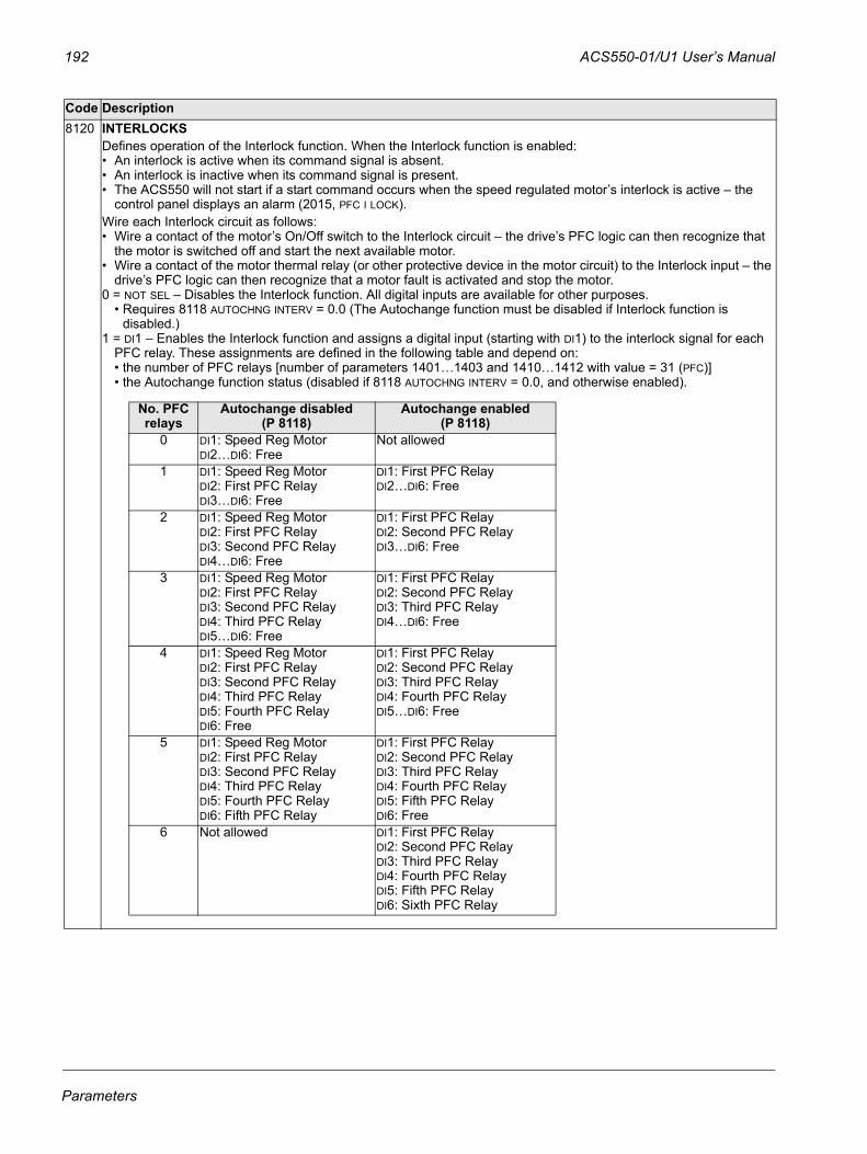
192 ACS550-01/U1 User’s Manual
8120 INTERLOCKSDefines operation of the Interlock function. When the Interlock function is enabled:• An interlock is active when its command signal is absent. • An interlock is inactive when its command signal is present.• The ACS550 will not start if a start command occurs when the speed regulated motor’s interlock is active – the
control panel displays an alarm (2015, PFC I LOCK).Wire each Interlock circuit as follows:• Wire a contact of the motor’s On/Off switch to the Interlock circuit – the drive’s PFC logic can then recognize that
the motor is switched off and start the next available motor.• Wire a contact of the motor thermal relay (or other protective device in the motor circuit) to the Interlock input – the
drive’s PFC logic can then recognize that a motor fault is activated and stop the motor.0 = NOT SEL – Disables the Interlock function. All digital inputs are available for other purposes.
• Requires 8118 AUTOCHNG INTERV = 0.0 (The Autochange function must be disabled if Interlock function is disabled.)
1 = DI1 – Enables the Interlock function and assigns a digital input (starting with DI1) to the interlock signal for each PFC relay. These assignments are defined in the following table and depend on:• the number of PFC relays [number of parameters 1401…1403 and 1410…1412 with value = 31 (PFC)]• the Autochange function status (disabled if 8118 AUTOCHNG INTERV = 0.0, and otherwise enabled).
Code Description
No. PFC relays
Autochange disabled (P 8118)
Autochange enabled(P 8118)
0 DI1: Speed Reg MotorDI2…DI6: Free
Not allowed
1 DI1: Speed Reg MotorDI2: First PFC RelayDI3…DI6: Free
DI1: First PFC RelayDI2…DI6: Free
2 DI1: Speed Reg MotorDI2: First PFC RelayDI3: Second PFC RelayDI4…DI6: Free
DI1: First PFC RelayDI2: Second PFC RelayDI3…DI6: Free
3 DI1: Speed Reg MotorDI2: First PFC RelayDI3: Second PFC RelayDI4: Third PFC RelayDI5…DI6: Free
DI1: First PFC RelayDI2: Second PFC RelayDI3: Third PFC RelayDI4…DI6: Free
4 DI1: Speed Reg MotorDI2: First PFC RelayDI3: Second PFC RelayDI4: Third PFC RelayDI5: Fourth PFC RelayDI6: Free
DI1: First PFC RelayDI2: Second PFC RelayDI3: Third PFC RelayDI4: Fourth PFC RelayDI5…DI6: Free
5 DI1: Speed Reg MotorDI2: First PFC RelayDI3: Second PFC RelayDI4: Third PFC RelayDI5: Fourth PFC RelayDI6: Fifth PFC Relay
DI1: First PFC RelayDI2: Second PFC RelayDI3: Third PFC RelayDI4: Fourth PFC RelayDI5: Fifth PFC RelayDI6: Free
6 Not allowed DI1: First PFC RelayDI2: Second PFC RelayDI3: Third PFC RelayDI4: Fourth PFC RelayDI5: Fifth PFC RelayDI6: Sixth PFC Relay
Parameters
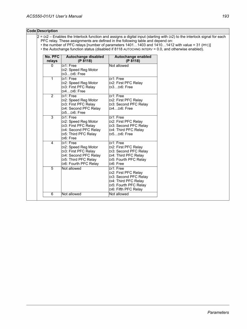
ACS550-01/U1 User’s Manual 193
2 = DI2 – Enables the Interlock function and assigns a digital input (starting with DI2) to the interlock signal for each PFC relay. These assignments are defined in the following table and depend on:• the number of PFC relays [number of parameters 1401…1403 and 1410…1412 with value = 31 (PFC)]• the Autochange function status (disabled if 8118 AUTOCHNG INTERV = 0.0, and otherwise enabled).
Code Description
No. PFC relays
Autochange disabled(P 8118)
Autochange enabled(P 8118)
0 DI1: FreeDI2: Speed Reg MotorDI3…DI6: Free
Not allowed
1 DI1: FreeDI2: Speed Reg MotorDI3: First PFC RelayDI4…DI6: Free
DI1: FreeDI2: First PFC RelayDI3…DI6: Free
2 DI1: FreeDI2: Speed Reg MotorDI3: First PFC RelayDI4: Second PFC RelayDI5…DI6: Free
DI1: FreeDI2: First PFC RelayDI3: Second PFC RelayDI4…DI6: Free
3 DI1: FreeDI2: Speed Reg MotorDI3: First PFC RelayDI4: Second PFC RelayDI5: Third PFC RelayDI6: Free
DI1: FreeDI2: First PFC RelayDI3: Second PFC RelayDI4: Third PFC RelayDI5…DI6: Free
4 DI1: FreeDI2: Speed Reg MotorDI3: First PFC RelayDI4: Second PFC RelayDI5: Third PFC RelayDI6: Fourth PFC Relay
DI1: FreeDI2: First PFC RelayDI3: Second PFC RelayDI4: Third PFC RelayDI5: Fourth PFC RelayDI6: Free
5 Not allowed DI1: FreeDI2: First PFC RelayDI3: Second PFC RelayDI4: Third PFC RelayDI5: Fourth PFC RelayDI6: Fifth PFC Relay
6 Not allowed Not allowed
Parameters
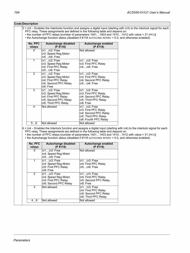
194 ACS550-01/U1 User’s Manual
3 = DI3 – Enables the Interlocks function and assigns a digital input (starting with DI3) to the interlock signal for each PFC relay. These assignments are defined in the following table and depend on:• the number of PFC relays [number of parameters 1401…1403 and 1410…1412 with value = 31 (PFC)]• the Autochange function status (disabled if 8118 AUTOCHNG INTERV = 0.0, and otherwise enabled).
4 = DI4 – Enables the Interlock function and assigns a digital input (starting with DI4) to the interlock signal for each PFC relay. These assignments are defined in the following table and depend on:• the number of PFC relays [number of parameters 1401…1403 and 1410…1412 with value = 31 (PFC)]• the Autochange function status (disabled if 8118 AUTOCHNG INTERV = 0.0, and otherwise enabled).
Code Description
No. PFC relays
Autochange disabled(P 8118)
Autochange enabled(P 8118)
0 DI1…DI2: FreeDI3: Speed Reg MotorDI4…DI6: Free
Not allowed
1 DI1…DI2: FreeDI3: Speed Reg MotorDI4: First PFC RelayDI5…DI6: Free
DI1…DI2: FreeDI3: First PFC RelayDI4…DI6: Free
2 DI1…DI2: FreeDI3: Speed Reg MotorDI4: First PFC RelayDI5: Second PFC RelayDI6: Free
DI1…DI2: FreeDI3: First PFC RelayDI4: Second PFC RelayDI5…DI6: Free
3 DI1…DI2: FreeDI3: Speed Reg MotorDI4: First PFC RelayDI5: Second PFC RelayDI6: Third PFC Relay
DI1…DI2: FreeDI3: First PFC RelayDI4: Second PFC RelayDI5: Third PFC RelayDI6: Free
4 Not allowed DI1…DI2: FreeDI3: First PFC RelayDI4: Second PFC RelayDI5: Third PFC RelayDI6: Fourth PFC Relay
5…6 Not allowed Not allowed
No. PFC relays
Autochange disabled(P 8118)
Autochange enabled(P 8118)
0 DI1…DI3: FreeDI4: Speed Reg MotorDI5…DI6: Free
Not allowed
1 DI1…DI3: FreeDI4: Speed Reg MotorDI5: First PFC RelayDI6: Free
DI1…DI3: FreeDI4: First PFC RelayDI5…DI6: Free
2 DI1…DI3: FreeDI4: Speed Reg MotorDI5: First PFC RelayDI6: Second PFC Relay
DI1…DI3: FreeDI4: First PFC RelayDI5: Second PFC RelayDI6: Free
3 Not allowed DI1…DI3: FreeDI4: First PFC RelayDI5: Second PFC RelayDI6: Third PFC Relay
4…6 Not allowed Not allowed
Parameters
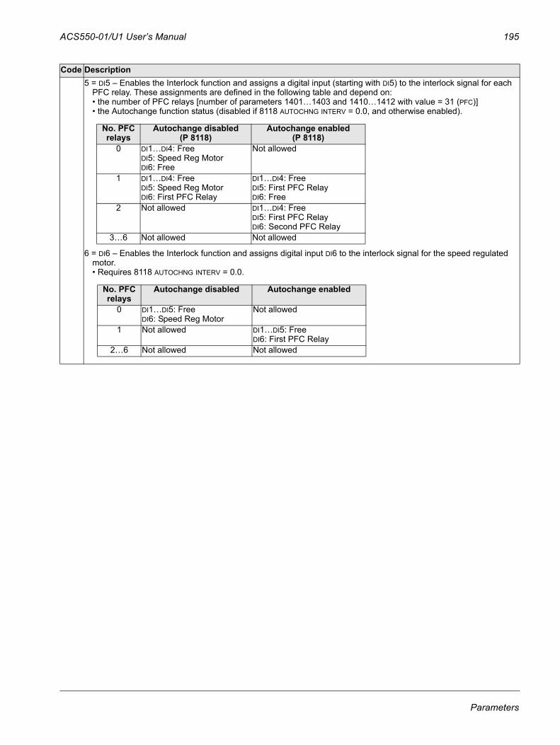
ACS550-01/U1 User’s Manual 195
5 = DI5 – Enables the Interlock function and assigns a digital input (starting with DI5) to the interlock signal for each PFC relay. These assignments are defined in the following table and depend on:• the number of PFC relays [number of parameters 1401…1403 and 1410…1412 with value = 31 (PFC)]• the Autochange function status (disabled if 8118 AUTOCHNG INTERV = 0.0, and otherwise enabled).
6 = DI6 – Enables the Interlock function and assigns digital input DI6 to the interlock signal for the speed regulated motor.• Requires 8118 AUTOCHNG INTERV = 0.0.
Code Description
No. PFC relays
Autochange disabled(P 8118)
Autochange enabled(P 8118)
0 DI1…DI4: FreeDI5: Speed Reg MotorDI6: Free
Not allowed
1 DI1…DI4: FreeDI5: Speed Reg MotorDI6: First PFC Relay
DI1…DI4: FreeDI5: First PFC RelayDI6: Free
2 Not allowed DI1…DI4: FreeDI5: First PFC RelayDI6: Second PFC Relay
3…6 Not allowed Not allowed
No. PFC relays
Autochange disabled Autochange enabled
0 DI1…DI5: FreeDI6: Speed Reg Motor
Not allowed
1 Not allowed DI1…DI5: FreeDI6: First PFC Relay
2…6 Not allowed Not allowed
Parameters
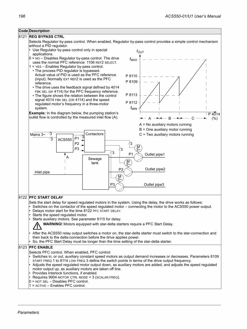
196 ACS550-01/U1 User’s Manual
8121 REG BYPASS CTRLSelects Regulator by-pass control. When enabled, Regulator by-pass control provides a simple control mechanism without a PID regulator.• Use Regulator by-pass control only in special
applications.0 = NO – Disables Regulator by-pass control. The drive
uses the normal PFC reference: 1106 REF2 SELECT.1 = YES – Enables Regulator by-pass control.
• The process PID regulator is bypassed.Actual value of PID is used as the PFC reference (input). Normally EXT REF2 is used as the PFC reference.
• The drive uses the feedback signal defined by 4014 FBK SEL (or 4114) for the PFC frequency reference.
• The figure shows the relation between the control signal 4014 FBK SEL (OR 4114) and the speed regulated motor’s frequency in a three-motor system.
Example: In the diagram below, the pumping station’s outlet flow is controlled by the measured inlet flow (A).
8122 PFC START DELAYSets the start delay for speed regulated motors in the system. Using the delay, the drive works as follows: • Switches on the contactor of the speed regulated motor – connecting the motor to the ACS550 power output.• Delays motor start for the time 8122 PFC START DELAY.• Starts the speed regulated motor. • Starts auxiliary motors. See parameter 8115 for delay.
WARNING! Motors equipped with star-delta starters require a PFC Start Delay.
• After the ACS550 relay output switches a motor on, the star-delta starter must switch to the star-connection and then back to the delta-connection before the drive applies power.
• So, the PFC Start Delay must be longer than the time setting of the star-delta starter.8123 PFC ENABLE
Selects PFC control. When enabled, PFC control:• Switches in, or out, auxiliary constant speed motors as output demand increases or decreases. Parameters 8109
START FREQ 1 to 8114 LOW FREQ 3 define the switch points in terms of the drive output frequency.• Adjusts the speed regulated motor output down, as auxiliary motors are added, and adjusts the speed regulated
motor output up, as auxiliary motors are taken off line.• Provides Interlock functions, if enabled.• Requires 9904 MOTOR CTRL MODE = 3 (SCALAR:FREQ).0 = NOT SEL – Disables PFC control.1 = ACTIVE – Enables PFC control.
Code Description
P 4014
P 8110P 8109
P 8113
P 8112
A = No auxiliary motors runningB = One auxiliary motor runningC = Two auxiliary motors running
A B C (%)
fOUT
fMIN
fMAX
M3~
M3~
M3~
Outlet pipe3
Outlet pipe2
Outlet pipe1P1
P2
P3
Sewagetank
ContactorsP1P2P3
Mains 3~
3
3
33
ACS55033
Inlet pipe
A
Parameters
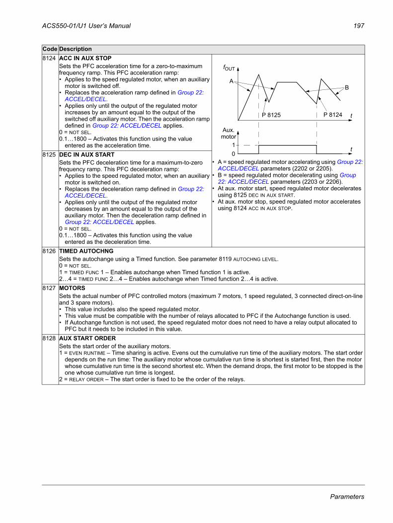
ACS550-01/U1 User’s Manual 197
8124 ACC IN AUX STOPSets the PFC acceleration time for a zero-to-maximum frequency ramp. This PFC acceleration ramp:• Applies to the speed regulated motor, when an auxiliary
motor is switched off.• Replaces the acceleration ramp defined in Group 22:
ACCEL/DECEL.• Applies only until the output of the regulated motor
increases by an amount equal to the output of the switched off auxiliary motor. Then the acceleration ramp defined in Group 22: ACCEL/DECEL applies.
0 = NOT SEL.0.1…1800 – Activates this function using the value
entered as the acceleration time.
• A = speed regulated motor accelerating using Group 22: ACCEL/DECEL parameters (2202 or 2205).
• B = speed regulated motor decelerating using Group 22: ACCEL/DECEL parameters (2203 or 2206).
• At aux. motor start, speed regulated motor decelerates using 8125 DEC IN AUX START.
• At aux. motor stop, speed regulated motor accelerates using 8124 ACC IN AUX STOP.
8125 DEC IN AUX STARTSets the PFC deceleration time for a maximum-to-zero frequency ramp. This PFC deceleration ramp:• Applies to the speed regulated motor, when an auxiliary
motor is switched on.• Replaces the deceleration ramp defined in Group 22:
ACCEL/DECEL.• Applies only until the output of the regulated motor
decreases by an amount equal to the output of the auxiliary motor. Then the deceleration ramp defined in Group 22: ACCEL/DECEL applies.
0 = NOT SEL.0.1…1800 – Activates this function using the value
entered as the deceleration time.8126 TIMED AUTOCHNG
Sets the autochange using a Timed function. See parameter 8119 AUTOCHNG LEVEL.0 = NOT SEL.1 = TIMED FUNC 1 – Enables autochange when Timed function 1 is active.2…4 = TIMED FUNC 2…4 – Enables autochange when Timed function 2…4 is active.
8127 MOTORSSets the actual number of PFC controlled motors (maximum 7 motors, 1 speed regulated, 3 connected direct-on-line and 3 spare motors).• This value includes also the speed regulated motor.• This value must be compatible with the number of relays allocated to PFC if the Autochange function is used.• If Autochange function is not used, the speed regulated motor does not need to have a relay output allocated to
PFC but it needs to be included in this value.8128 AUX START ORDER
Sets the start order of the auxiliary motors.1 = EVEN RUNTIME – Time sharing is active. Evens out the cumulative run time of the auxiliary motors. The start order
depends on the run time: The auxiliary motor whose cumulative run time is shortest is started first, then the motor whose cumulative run time is the second shortest etc. When the demand drops, the first motor to be stopped is the one whose cumulative run time is longest.
2 = RELAY ORDER – The start order is fixed to be the order of the relays.
Code Description
P 8125 P 8124
AB
10
Aux.motor
fOUT
t
t
Parameters
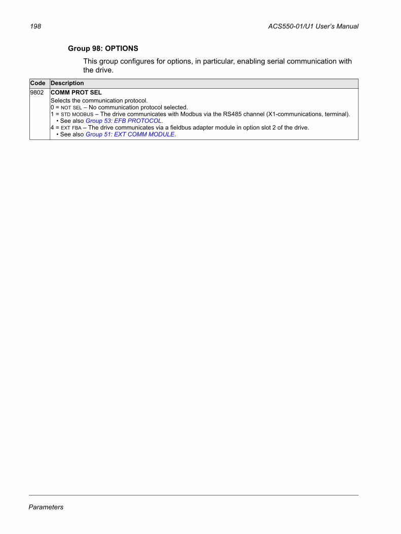
198 ACS550-01/U1 User’s Manual
Group 98: OPTIONSThis group configures for options, in particular, enabling serial communication with the drive.
Code Description9802 COMM PROT SEL
Selects the communication protocol.0 = NOT SEL – No communication protocol selected.1 = STD MODBUS – The drive communicates with Modbus via the RS485 channel (X1-communications, terminal).
• See also Group 53: EFB PROTOCOL.4 = EXT FBA – The drive communicates via a fieldbus adapter module in option slot 2 of the drive.
• See also Group 51: EXT COMM MODULE.
Parameters
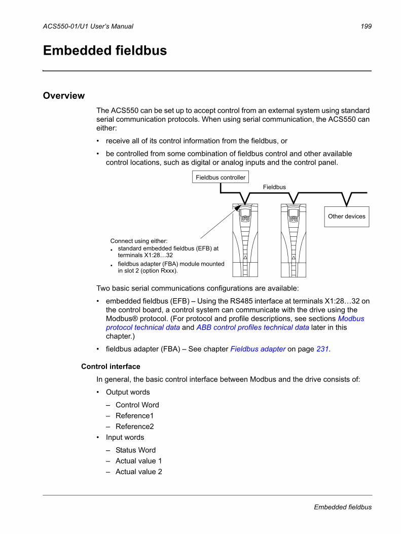
ACS550-01/U1 User’s Manual 199
Embedded fieldbus
OverviewThe ACS550 can be set up to accept control from an external system using standard serial communication protocols. When using serial communication, the ACS550 can either:
• receive all of its control information from the fieldbus, or
• be controlled from some combination of fieldbus control and other available control locations, such as digital or analog inputs and the control panel.
Two basic serial communications configurations are available:
• embedded fieldbus (EFB) – Using the RS485 interface at terminals X1:28…32 on the control board, a control system can communicate with the drive using the Modbus® protocol. (For protocol and profile descriptions, see sections Modbus protocol technical data and ABB control profiles technical data later in this chapter.)
• fieldbus adapter (FBA) – See chapter Fieldbus adapter on page 231.
Control interfaceIn general, the basic control interface between Modbus and the drive consists of:
• Output words
– Control Word– Reference1– Reference2
• Input words
– Status Word– Actual value 1– Actual value 2
FieldbusFieldbus controller
Other devices
Connect using either:• standard embedded fieldbus (EFB) at
terminals X1:28…32
• fieldbus adapter (FBA) module mounted in slot 2 (option Rxxx).
Embedded fieldbus
200 ACS550-01/U1 User’s Manual
– Actual value 3– Actual value 4– Actual value 5– Actual value 6– Actual value 7– Actual value 8
The content of these words is defined by profiles. For details on the profiles used, sees section ABB control profiles technical data on page 219.
Note: The words “output” and “input” are used as seen from the fieldbus controller point of view. For example an output describes data flow from the fieldbus controller to the drive and appears as an input from the drive point of view.
PlanningNetwork planning should address the following questions:
• What types and quantities of devices must be connected to the network?
• What control information must be sent down to the drives?
• What feedback information must be sent from the drives to the controlling system?
Mechanical and electrical installation – EFB
WARNING! Connections should be made only while the drive is disconnected from the power source.
Drive terminals 28…32 are for RS485 communications.
• Use Belden 9842 or equivalent. Belden 9842 is a dual twisted, shielded pair cable with a wave impedance of 120 ohm.
• Use one of these twisted shielded pairs for the RS485 link. Use this pair to connect all A (-) terminals together and all B (+) terminals together.
• Use one of the wires in the other pair for the logical ground (terminal 31), leaving one wire unused.
• Do not directly ground the RS485 network at any point. Ground all devices on the network using their corresponding earthing terminals.
• As always, the grounding wires should not form any closed loops, and all the devices should be earthed to a common ground.
• Connect the RS485 link in a daisy-chained bus, without dropout lines.
Embedded fieldbus
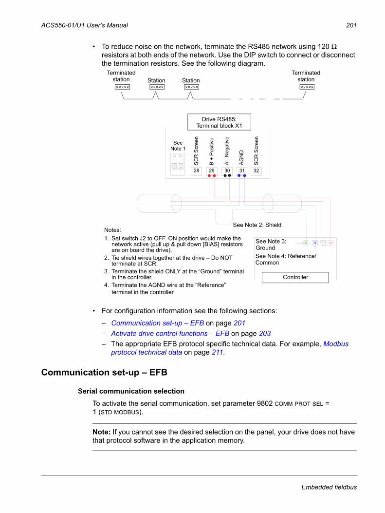
ACS550-01/U1 User’s Manual 201
• To reduce noise on the network, terminate the RS485 network using 120 Ω resistors at both ends of the network. Use the DIP switch to connect or disconnect the termination resistors. See the following diagram.
• For configuration information see the following sections:
– Communication set-up – EFB on page 201– Activate drive control functions – EFB on page 203 – The appropriate EFB protocol specific technical data. For example, Modbus
protocol technical data on page 211.
Communication set-up – EFB
Serial communication selectionTo activate the serial communication, set parameter 9802 COMM PROT SEL = 1 (STD MODBUS).
Note: If you cannot see the desired selection on the panel, your drive does not have that protocol software in the application memory.
Terminated Terminatedstation Station Station station
1. Use 3 Conductor Cable - Tie 3rd Wire to AGND: X1-31.
NOTES:
28 29 30 31 32
SC
R S
cree
n
B +
Pos
itive
A -
Neg
ativ
e
AG
ND
SC
R S
cree
n
See Note 3: Shield
See Note 2
ACH 550 RS485: Terminal Block -X1
Building AutomationController
G - +RSee Note 4: Ground
4. Terminate shield ONLY at "Ground" terminal in the Building Automation Controller!5. Terminate AGN wire at "Reference" terminal in the Building Automation Controller!
2. Set switch J2 to OFF. BUS termination is an active network: Pull Up & Pull Down (BIAS) resistors are on board the ACH550 Drive!3. Tie shield wires together at Drive - Do Not terminate at SCR!
See Note 5: Reference/Common
PREFERRED WIRING:3 Conductor with Shield
Notes:1. Set switch J2 to OFF. ON position would make the
network active (pull up & pull down [BIAS] resistors are on board the drive).
2. Tie shield wires together at the drive – Do NOT terminate at SCR.
3. Terminate the shield ONLY at the “Ground” terminal in the controller.
4. Terminate the AGND wire at the “Reference” terminal in the controller.
SeeNote 1
SC
R S
cree
n
SC
R S
cree
n
B +
Pos
itive
A -
Neg
ativ
e
AG
ND
Drive RS485:Terminal block X1
Controller
See Note 2: Shield
See Note 3:GroundSee Note 4: Reference/Common
Embedded fieldbus
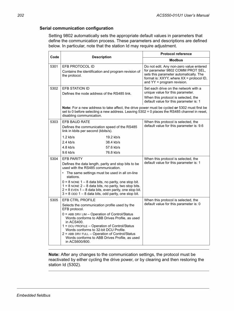
202 ACS550-01/U1 User’s Manual
Serial communication configurationSetting 9802 automatically sets the appropriate default values in parameters that define the communication process. These parameters and descriptions are defined below. In particular, note that the station Id may require adjustment.
Note: After any changes to the communication settings, the protocol must be reactivated by either cycling the drive power, or by clearing and then restoring the station Id (5302).
Code DescriptionProtocol reference
Modbus
5301 EFB PROTOCOL IDContains the identification and program revision of the protocol.
Do not edit. Any non-zero value entered for parameter 9802 COMM PROT SEL, sets this parameter automatically. The format is: XXYY, where XX = protocol ID, and YY = program revision.
5302 EFB STATION IDDefines the node address of the RS485 link.
Set each drive on the network with a unique value for this parameter.When this protocol is selected, the default value for this parameter is: 1
Note: For a new address to take affect, the drive power must be cycled or 5302 must first be set to 0 before selecting a new address. Leaving 5302 = 0 places the RS485 channel in reset, disabling communication.
5303 EFB BAUD RATEDefines the communication speed of the RS485 link in kbits per second (kbits/s).
When this protocol is selected, the default value for this parameter is: 9.6
1.2 kb/s2.4 kb/s4.8 kb/s9.6 kb/s
19.2 kb/s38.4 kb/s57.6 kb/s76.8 kb/s
5304 EFB PARITYDefines the data length, parity and stop bits to be used with the RS485 communication. • The same settings must be used in all on-line
stations.0 = 8 NONE 1 – 8 data bits, no parity, one stop bit.1 = 8 NONE 2 – 8 data bits, no parity, two stop bits.2 = 8 EVEN 1 – 8 data bits, even parity, one stop bit.3 = 8 ODD 1 – 8 data bits, odd parity, one stop bit.
When this protocol is selected, the default value for this parameter is: 1
5305 EFB CTRL PROFILESelects the communication profile used by the EFB protocol.0 = ABB DRV LIM – Operation of Control/Status
Words conforms to ABB Drives Profile, as used in ACS400.
1 = DCU PROFILE – Operation of Control/Status Words conforms to 32-bit DCU Profile.
2 = ABB DRV FULL – Operation of Control/Status Words conforms to ABB Drives Profile, as used in ACS600/800.
When this protocol is selected, the default value for this parameter is: 0
Embedded fieldbus
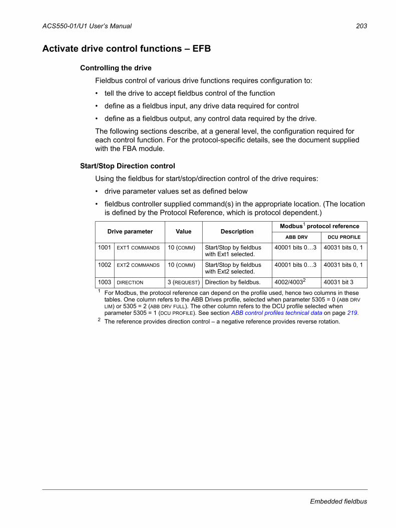
ACS550-01/U1 User’s Manual 203
Activate drive control functions – EFB
Controlling the driveFieldbus control of various drive functions requires configuration to:
• tell the drive to accept fieldbus control of the function
• define as a fieldbus input, any drive data required for control
• define as a fieldbus output, any control data required by the drive.
The following sections describe, at a general level, the configuration required for each control function. For the protocol-specific details, see the document supplied with the FBA module.
Start/Stop Direction controlUsing the fieldbus for start/stop/direction control of the drive requires:
• drive parameter values set as defined below
• fieldbus controller supplied command(s) in the appropriate location. (The location is defined by the Protocol Reference, which is protocol dependent.)
Drive parameter Value DescriptionModbus1 protocol reference
ABB DRV DCU PROFILE
1001 EXT1 COMMANDS 10 (COMM) Start/Stop by fieldbus with Ext1 selected.
40001 bits 0…3 40031 bits 0, 1
1002 EXT2 COMMANDS 10 (COMM) Start/Stop by fieldbus with Ext2 selected.
40001 bits 0…3 40031 bits 0, 1
1003 DIRECTION 3 (REQUEST) Direction by fieldbus. 4002/40032 40031 bit 31 For Modbus, the protocol reference can depend on the profile used, hence two columns in these
tables. One column refers to the ABB Drives profile, selected when parameter 5305 = 0 (ABB DRV LIM) or 5305 = 2 (ABB DRV FULL). The other column refers to the DCU profile selected when parameter 5305 = 1 (DCU PROFILE). See section ABB control profiles technical data on page 219.
2 The reference provides direction control – a negative reference provides reverse rotation.
Embedded fieldbus
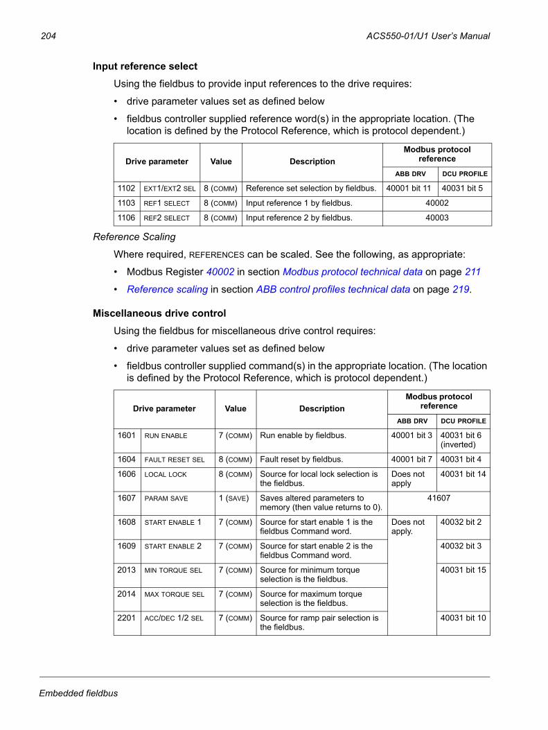
204 ACS550-01/U1 User’s Manual
Input reference selectUsing the fieldbus to provide input references to the drive requires:
• drive parameter values set as defined below
• fieldbus controller supplied reference word(s) in the appropriate location. (The location is defined by the Protocol Reference, which is protocol dependent.)
Reference Scaling
Where required, REFERENCES can be scaled. See the following, as appropriate:
• Modbus Register 40002 in section Modbus protocol technical data on page 211
• Reference scaling in section ABB control profiles technical data on page 219.
Miscellaneous drive controlUsing the fieldbus for miscellaneous drive control requires:
• drive parameter values set as defined below
• fieldbus controller supplied command(s) in the appropriate location. (The location is defined by the Protocol Reference, which is protocol dependent.)
Drive parameter Value DescriptionModbus protocol
reference
ABB DRV DCU PROFILE
1102 EXT1/EXT2 SEL 8 (COMM) Reference set selection by fieldbus. 40001 bit 11 40031 bit 5
1103 REF1 SELECT 8 (COMM) Input reference 1 by fieldbus. 40002
1106 REF2 SELECT 8 (COMM) Input reference 2 by fieldbus. 40003
Drive parameter Value DescriptionModbus protocol
reference
ABB DRV DCU PROFILE
1601 RUN ENABLE 7 (COMM) Run enable by fieldbus. 40001 bit 3 40031 bit 6(inverted)
1604 FAULT RESET SEL 8 (COMM) Fault reset by fieldbus. 40001 bit 7 40031 bit 4
1606 LOCAL LOCK 8 (COMM) Source for local lock selection is the fieldbus.
Does not apply
40031 bit 14
1607 PARAM SAVE 1 (SAVE) Saves altered parameters to memory (then value returns to 0).
41607
1608 START ENABLE 1 7 (COMM) Source for start enable 1 is the fieldbus Command word.
Does not apply.
40032 bit 2
1609 START ENABLE 2 7 (COMM) Source for start enable 2 is the fieldbus Command word.
40032 bit 3
2013 MIN TORQUE SEL 7 (COMM) Source for minimum torque selection is the fieldbus.
40031 bit 15
2014 MAX TORQUE SEL 7 (COMM) Source for maximum torque selection is the fieldbus.
2201 ACC/DEC 1/2 SEL 7 (COMM) Source for ramp pair selection is the fieldbus.
40031 bit 10
Embedded fieldbus
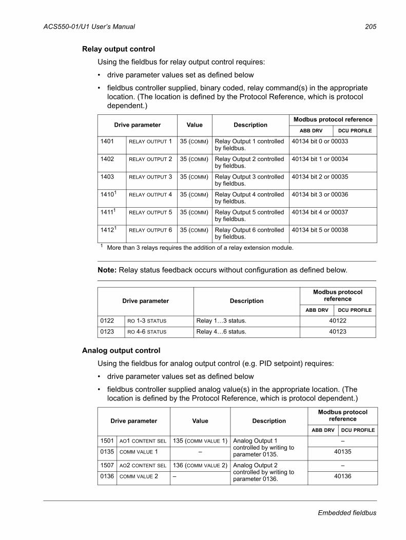
ACS550-01/U1 User’s Manual 205
Relay output controlUsing the fieldbus for relay output control requires:
• drive parameter values set as defined below
• fieldbus controller supplied, binary coded, relay command(s) in the appropriate location. (The location is defined by the Protocol Reference, which is protocol dependent.)
Note: Relay status feedback occurs without configuration as defined below.
Analog output controlUsing the fieldbus for analog output control (e.g. PID setpoint) requires:
• drive parameter values set as defined below
• fieldbus controller supplied analog value(s) in the appropriate location. (The location is defined by the Protocol Reference, which is protocol dependent.)
Drive parameter Value DescriptionModbus protocol reference
ABB DRV DCU PROFILE
1401 RELAY OUTPUT 1 35 (COMM) Relay Output 1 controlled by fieldbus.
40134 bit 0 or 00033
1402 RELAY OUTPUT 2 35 (COMM) Relay Output 2 controlled by fieldbus.
40134 bit 1 or 00034
1403 RELAY OUTPUT 3 35 (COMM) Relay Output 3 controlled by fieldbus.
40134 bit 2 or 00035
14101 RELAY OUTPUT 4 35 (COMM) Relay Output 4 controlled by fieldbus.
40134 bit 3 or 00036
14111 RELAY OUTPUT 5 35 (COMM) Relay Output 5 controlled by fieldbus.
40134 bit 4 or 00037
14121 RELAY OUTPUT 6 35 (COMM) Relay Output 6 controlled by fieldbus.
40134 bit 5 or 00038
1 More than 3 relays requires the addition of a relay extension module.
Drive parameter DescriptionModbus protocol
reference
ABB DRV DCU PROFILE
0122 RO 1-3 STATUS Relay 1…3 status. 40122
0123 RO 4-6 STATUS Relay 4…6 status. 40123
Drive parameter Value DescriptionModbus protocol
reference
ABB DRV DCU PROFILE
1501 AO1 CONTENT SEL 135 (COMM VALUE 1) Analog Output 1 controlled by writing to parameter 0135.
–
0135 COMM VALUE 1 – 40135
1507 AO2 CONTENT SEL 136 (COMM VALUE 2) Analog Output 2 controlled by writing to parameter 0136.
–
0136 COMM VALUE 2 – 40136
Embedded fieldbus
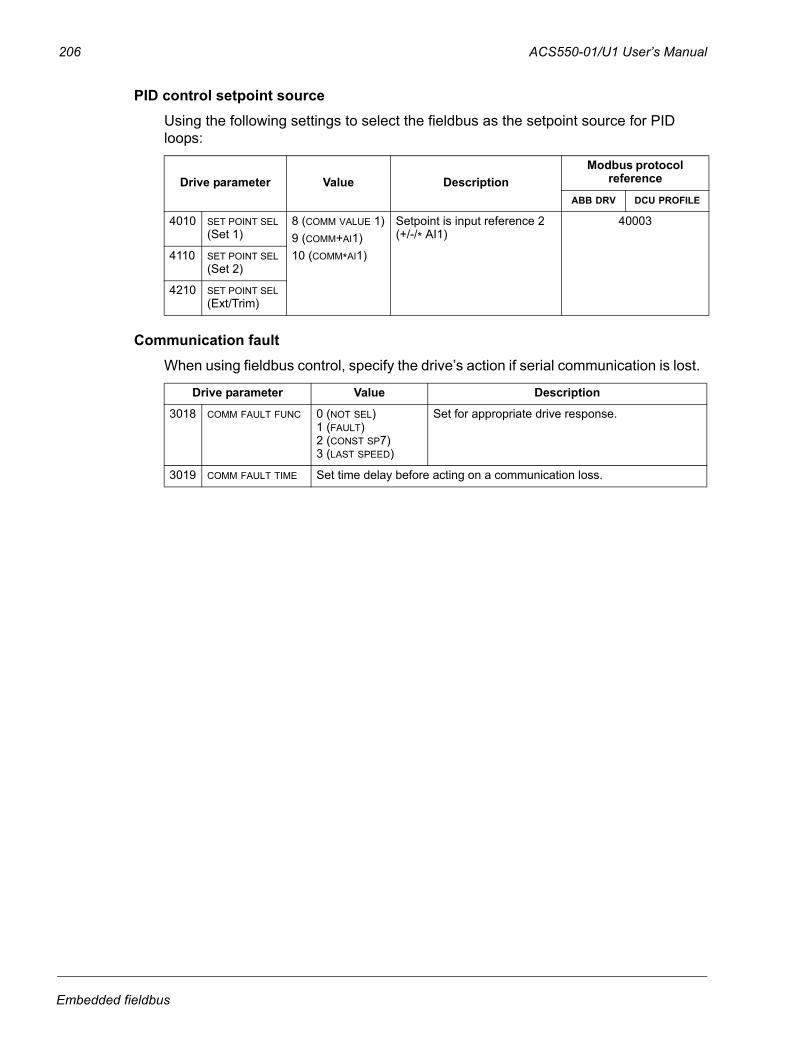
206 ACS550-01/U1 User’s Manual
PID control setpoint source Using the following settings to select the fieldbus as the setpoint source for PID loops:
Communication faultWhen using fieldbus control, specify the drive’s action if serial communication is lost.
Drive parameter Value DescriptionModbus protocol
reference
ABB DRV DCU PROFILE
4010 SET POINT SEL (Set 1)
8 (COMM VALUE 1)9 (COMM+AI1)10 (COMM*AI1)
Setpoint is input reference 2 (+/-/* AI1)
40003
4110 SET POINT SEL (Set 2)
4210 SET POINT SEL (Ext/Trim)
Drive parameter Value Description
3018 COMM FAULT FUNC 0 (NOT SEL)1 (FAULT)2 (CONST SP7)3 (LAST SPEED)
Set for appropriate drive response.
3019 COMM FAULT TIME Set time delay before acting on a communication loss.
Embedded fieldbus
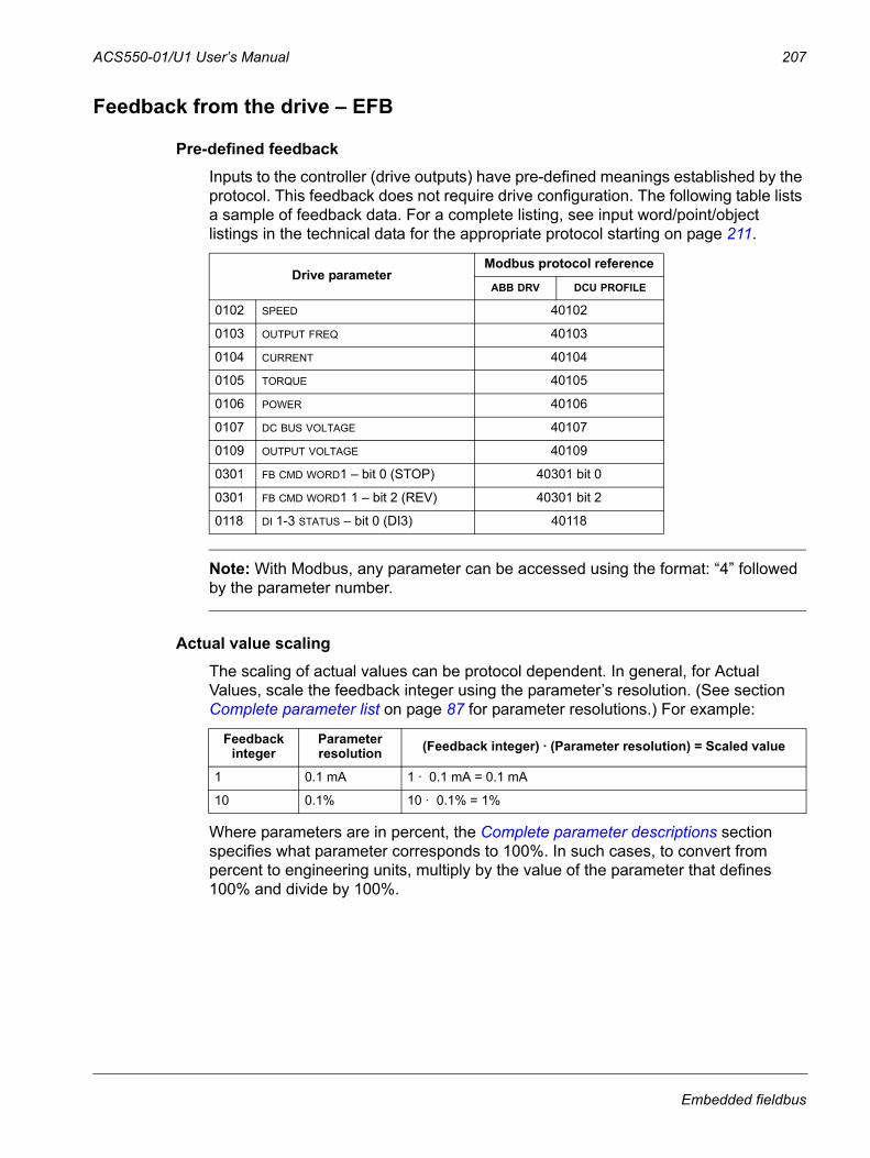
ACS550-01/U1 User’s Manual 207
Feedback from the drive – EFB
Pre-defined feedbackInputs to the controller (drive outputs) have pre-defined meanings established by the protocol. This feedback does not require drive configuration. The following table lists a sample of feedback data. For a complete listing, see input word/point/object listings in the technical data for the appropriate protocol starting on page 211.
Note: With Modbus, any parameter can be accessed using the format: “4” followed by the parameter number.
Actual value scalingThe scaling of actual values can be protocol dependent. In general, for Actual Values, scale the feedback integer using the parameter’s resolution. (See section Complete parameter list on page 87 for parameter resolutions.) For example:
Where parameters are in percent, the Complete parameter descriptions section specifies what parameter corresponds to 100%. In such cases, to convert from percent to engineering units, multiply by the value of the parameter that defines 100% and divide by 100%.
Drive parameterModbus protocol reference
ABB DRV DCU PROFILE
0102 SPEED 40102
0103 OUTPUT FREQ 40103
0104 CURRENT 40104
0105 TORQUE 40105
0106 POWER 40106
0107 DC BUS VOLTAGE 40107
0109 OUTPUT VOLTAGE 40109
0301 FB CMD WORD1 – bit 0 (STOP) 40301 bit 0
0301 FB CMD WORD1 1 – bit 2 (REV) 40301 bit 2
0118 DI 1-3 STATUS – bit 0 (DI3) 40118
Feedback integer
Parameter resolution (Feedback integer) · (Parameter resolution) = Scaled value
1 0.1 mA 1 · 0.1 mA = 0.1 mA
10 0.1% 10 · 0.1% = 1%
Embedded fieldbus
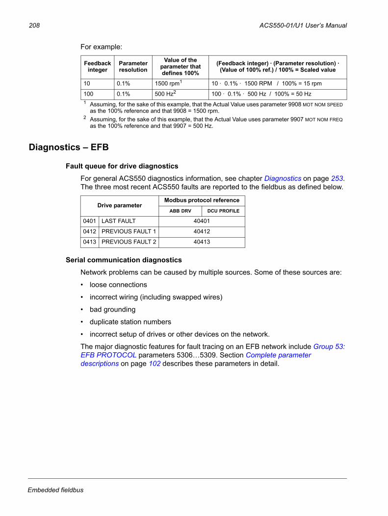
208 ACS550-01/U1 User’s Manual
For example:
Diagnostics – EFB
Fault queue for drive diagnosticsFor general ACS550 diagnostics information, see chapter Diagnostics on page 253. The three most recent ACS550 faults are reported to the fieldbus as defined below.
Serial communication diagnosticsNetwork problems can be caused by multiple sources. Some of these sources are:
• loose connections
• incorrect wiring (including swapped wires)
• bad grounding
• duplicate station numbers
• incorrect setup of drives or other devices on the network.
The major diagnostic features for fault tracing on an EFB network include Group 53: EFB PROTOCOL parameters 5306…5309. Section Complete parameter descriptions on page 102 describes these parameters in detail.
Feedback integer
Parameter resolution
Value of the parameter that defines 100%
(Feedback integer) · (Parameter resolution) · (Value of 100% ref.) / 100% = Scaled value
10 0.1% 1500 rpm1 10 · 0.1% · 1500 RPM / 100% = 15 rpm
100 0.1% 500 Hz2 100 · 0.1% · 500 Hz / 100% = 50 Hz1 Assuming, for the sake of this example, that the Actual Value uses parameter 9908 MOT NOM SPEED
as the 100% reference and that 9908 = 1500 rpm.2 Assuming, for the sake of this example, that the Actual Value uses parameter 9907 MOT NOM FREQ
as the 100% reference and that 9907 = 500 Hz.
Drive parameterModbus protocol reference
ABB DRV DCU PROFILE
0401 LAST FAULT 40401
0412 PREVIOUS FAULT 1 40412
0413 PREVIOUS FAULT 2 40413
Embedded fieldbus
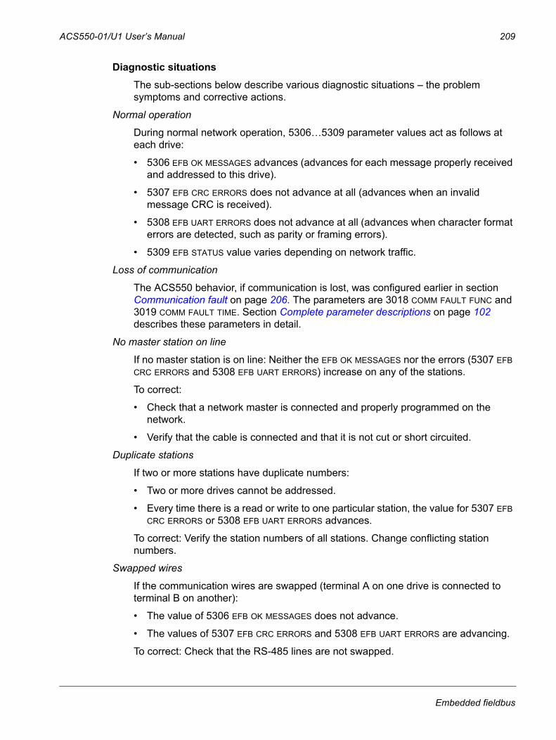
ACS550-01/U1 User’s Manual 209
Diagnostic situationsThe sub-sections below describe various diagnostic situations – the problem symptoms and corrective actions.
Normal operation
During normal network operation, 5306…5309 parameter values act as follows at each drive:
• 5306 EFB OK MESSAGES advances (advances for each message properly received and addressed to this drive).
• 5307 EFB CRC ERRORS does not advance at all (advances when an invalid message CRC is received).
• 5308 EFB UART ERRORS does not advance at all (advances when character format errors are detected, such as parity or framing errors).
• 5309 EFB STATUS value varies depending on network traffic.
Loss of communication
The ACS550 behavior, if communication is lost, was configured earlier in section Communication fault on page 206. The parameters are 3018 COMM FAULT FUNC and 3019 COMM FAULT TIME. Section Complete parameter descriptions on page 102 describes these parameters in detail.
No master station on line
If no master station is on line: Neither the EFB OK MESSAGES nor the errors (5307 EFB CRC ERRORS and 5308 EFB UART ERRORS) increase on any of the stations.
To correct:
• Check that a network master is connected and properly programmed on the network.
• Verify that the cable is connected and that it is not cut or short circuited.
Duplicate stations
If two or more stations have duplicate numbers:
• Two or more drives cannot be addressed.
• Every time there is a read or write to one particular station, the value for 5307 EFB CRC ERRORS or 5308 EFB UART ERRORS advances.
To correct: Verify the station numbers of all stations. Change conflicting station numbers.
Swapped wires
If the communication wires are swapped (terminal A on one drive is connected to terminal B on another):
• The value of 5306 EFB OK MESSAGES does not advance.
• The values of 5307 EFB CRC ERRORS and 5308 EFB UART ERRORS are advancing.
To correct: Check that the RS-485 lines are not swapped.
Embedded fieldbus
210 ACS550-01/U1 User’s Manual
Fault 28 – Serial 1 Err
If the drive’s control panel shows fault code 28, SERIAL 1 ERR, check for either of the following:
• The master system is down. To correct, resolve problem with master system.
• The communication connection is bad. To correct, check communication connection at the drive.
• The time-out selection for the drive is too short for the given installation. The master is not polling the drive within the specified time-out delay. To correct, increase the time set by parameter 3019 COMM FAULT TIME.
Faults 31…33 – EFB1…EFB3
The three EFB fault codes listed for the drive in chapter Diagnostics on page 253 (fault codes 31…33) are not used.
Intermittent off-line occurrences
The problems described above are the most common problems encountered with ACS550 serial communication. Intermittent problems might also be caused by:
• marginally loose connections
• wear on wires caused by equipment vibrations
• insufficient grounding and shielding on both the devices and on the communication cables.
Embedded fieldbus
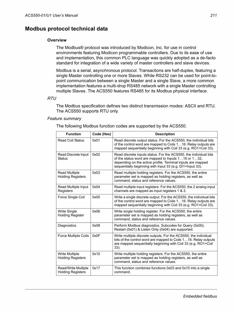
ACS550-01/U1 User’s Manual 211
Modbus protocol technical data
OverviewThe Modbus® protocol was introduced by Modicon, Inc. for use in control environments featuring Modicon programmable controllers. Due to its ease of use and implementation, this common PLC language was quickly adopted as a de-facto standard for integration of a wide variety of master controllers and slave devices.
Modbus is a serial, asynchronous protocol. Transactions are half-duplex, featuring a single Master controlling one or more Slaves. While RS232 can be used for point-to-point communication between a single Master and a single Slave, a more common implementation features a multi-drop RS485 network with a single Master controlling multiple Slaves. The ACS550 features RS485 for its Modbus physical interface.
RTU
The Modbus specification defines two distinct transmission modes: ASCII and RTU. The ACS550 supports RTU only.
Feature summary
The following Modbus function codes are supported by the ACS550.
Function Code (Hex) Description
Read Coil Status 0x01 Read discrete output status. For the ACS550, the individual bits of the control word are mapped to Coils 1…16. Relay outputs are mapped sequentially beginning with Coil 33 (e.g. RO1=Coil 33).
Read Discrete Input Status
0x02 Read discrete inputs status. For the ACS550, the individual bits of the status word are mapped to Inputs 1…16 or 1…32, depending on the active profile. Terminal inputs are mapped sequentially beginning with Input 33 (e.g. DI1=Input 33).
Read Multiple Holding Registers
0x03 Read multiple holding registers. For the ACS550, the entire parameter set is mapped as holding registers, as well as command, status and reference values.
Read Multiple Input Registers
0x04 Read multiple input registers. For the ACS550, the 2 analog input channels are mapped as input registers 1 & 2.
Force Single Coil 0x05 Write a single discrete output. For the ACS550, the individual bits of the control word are mapped to Coils 1…16. Relay outputs are mapped sequentially beginning with Coil 33 (e.g. RO1=Coil 33).
Write Single Holding Register
0x06 Write single holding register. For the ACS550, the entire parameter set is mapped as holding registers, as well as command, status and reference values.
Diagnostics 0x08 Perform Modbus diagnostics. Subcodes for Query (0x00), Restart (0x01) & Listen Only (0x04) are supported.
Force Multiple Coils 0x0F Write multiple discrete outputs. For the ACS550, the individual bits of the control word are mapped to Coils 1…16. Relay outputs are mapped sequentially beginning with Coil 33 (e.g. RO1=Coil 33).
Write Multiple Holding Registers
0x10 Write multiple holding registers. For the ACS550, the entire parameter set is mapped as holding registers, as well as command, status and reference values.
Read/Write Multiple Holding Registers
0x17 This function combines functions 0x03 and 0x10 into a single command.
Embedded fieldbus
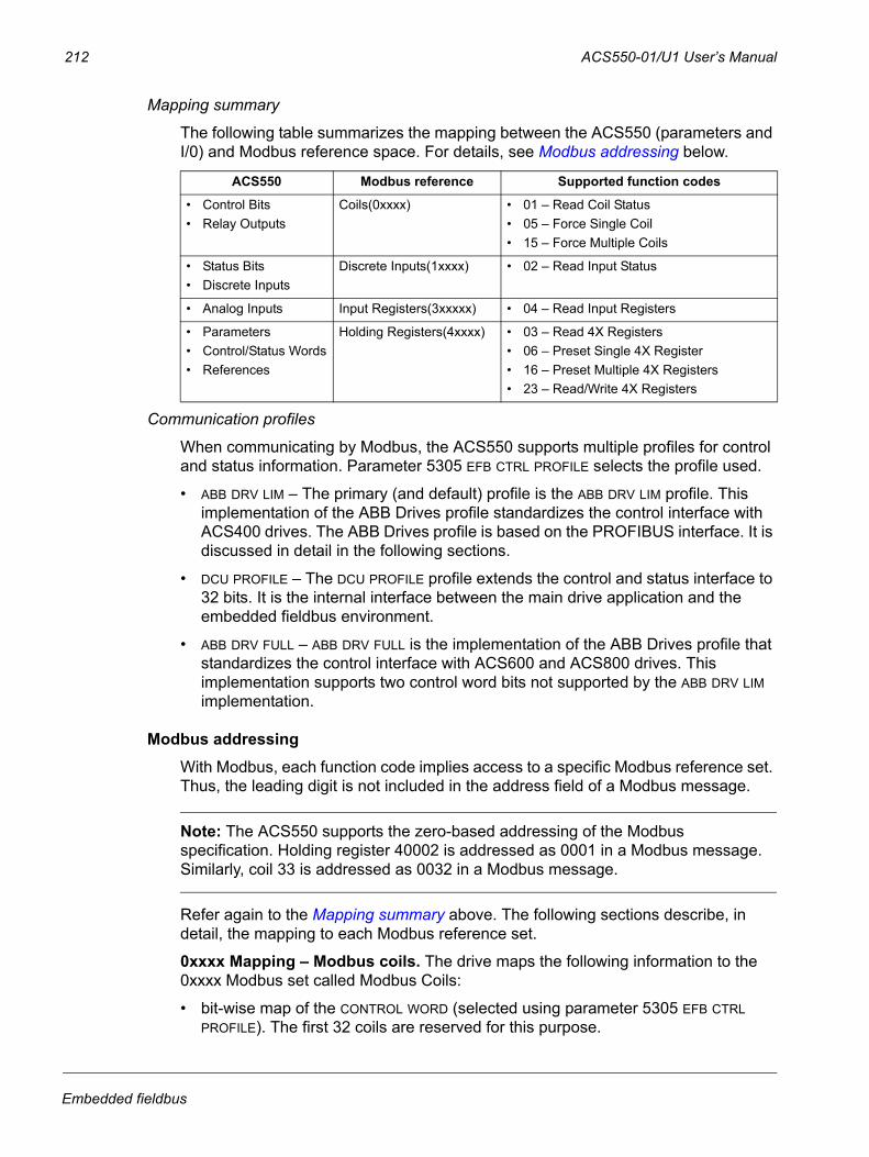
212 ACS550-01/U1 User’s Manual
Mapping summary
The following table summarizes the mapping between the ACS550 (parameters and I/0) and Modbus reference space. For details, see Modbus addressing below.
Communication profiles
When communicating by Modbus, the ACS550 supports multiple profiles for control and status information. Parameter 5305 EFB CTRL PROFILE selects the profile used.
• ABB DRV LIM – The primary (and default) profile is the ABB DRV LIM profile. This implementation of the ABB Drives profile standardizes the control interface with ACS400 drives. The ABB Drives profile is based on the PROFIBUS interface. It is discussed in detail in the following sections.
• DCU PROFILE – The DCU PROFILE profile extends the control and status interface to 32 bits. It is the internal interface between the main drive application and the embedded fieldbus environment.
• ABB DRV FULL – ABB DRV FULL is the implementation of the ABB Drives profile that standardizes the control interface with ACS600 and ACS800 drives. This implementation supports two control word bits not supported by the ABB DRV LIM implementation.
Modbus addressingWith Modbus, each function code implies access to a specific Modbus reference set. Thus, the leading digit is not included in the address field of a Modbus message.
Note: The ACS550 supports the zero-based addressing of the Modbus specification. Holding register 40002 is addressed as 0001 in a Modbus message. Similarly, coil 33 is addressed as 0032 in a Modbus message.
Refer again to the Mapping summary above. The following sections describe, in detail, the mapping to each Modbus reference set.
0xxxx Mapping – Modbus coils. The drive maps the following information to the 0xxxx Modbus set called Modbus Coils:
• bit-wise map of the CONTROL WORD (selected using parameter 5305 EFB CTRL PROFILE). The first 32 coils are reserved for this purpose.
ACS550 Modbus reference Supported function codes
• Control Bits• Relay Outputs
Coils(0xxxx) • 01 – Read Coil Status• 05 – Force Single Coil• 15 – Force Multiple Coils
• Status Bits• Discrete Inputs
Discrete Inputs(1xxxx) • 02 – Read Input Status
• Analog Inputs Input Registers(3xxxxx) • 04 – Read Input Registers
• Parameters• Control/Status Words• References
Holding Registers(4xxxx) • 03 – Read 4X Registers• 06 – Preset Single 4X Register• 16 – Preset Multiple 4X Registers• 23 – Read/Write 4X Registers
Embedded fieldbus
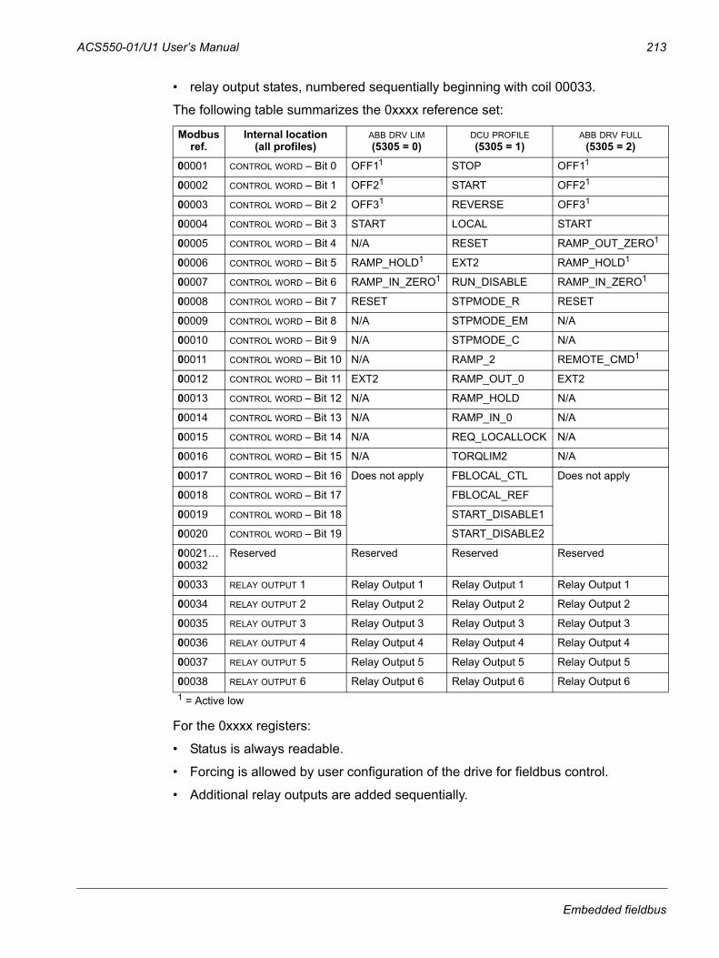
ACS550-01/U1 User’s Manual 213
• relay output states, numbered sequentially beginning with coil 00033.
The following table summarizes the 0xxxx reference set:
For the 0xxxx registers:
• Status is always readable.
• Forcing is allowed by user configuration of the drive for fieldbus control.
• Additional relay outputs are added sequentially.
Modbus ref.
Internal location(all profiles)
ABB DRV LIM (5305 = 0)
DCU PROFILE (5305 = 1)
ABB DRV FULL (5305 = 2)
00001 CONTROL WORD – Bit 0 OFF11 STOP OFF11
00002 CONTROL WORD – Bit 1 OFF21 START OFF21
00003 CONTROL WORD – Bit 2 OFF31 REVERSE OFF31
00004 CONTROL WORD – Bit 3 START LOCAL START
00005 CONTROL WORD – Bit 4 N/A RESET RAMP_OUT_ZERO1
00006 CONTROL WORD – Bit 5 RAMP_HOLD1 EXT2 RAMP_HOLD1
00007 CONTROL WORD – Bit 6 RAMP_IN_ZERO1 RUN_DISABLE RAMP_IN_ZERO1
00008 CONTROL WORD – Bit 7 RESET STPMODE_R RESET
00009 CONTROL WORD – Bit 8 N/A STPMODE_EM N/A
00010 CONTROL WORD – Bit 9 N/A STPMODE_C N/A
00011 CONTROL WORD – Bit 10 N/A RAMP_2 REMOTE_CMD1
00012 CONTROL WORD – Bit 11 EXT2 RAMP_OUT_0 EXT2
00013 CONTROL WORD – Bit 12 N/A RAMP_HOLD N/A
00014 CONTROL WORD – Bit 13 N/A RAMP_IN_0 N/A
00015 CONTROL WORD – Bit 14 N/A REQ_LOCALLOCK N/A
00016 CONTROL WORD – Bit 15 N/A TORQLIM2 N/A
00017 CONTROL WORD – Bit 16 Does not apply FBLOCAL_CTL Does not apply
00018 CONTROL WORD – Bit 17 FBLOCAL_REF
00019 CONTROL WORD – Bit 18 START_DISABLE1
00020 CONTROL WORD – Bit 19 START_DISABLE2
00021…00032
Reserved Reserved Reserved Reserved
00033 RELAY OUTPUT 1 Relay Output 1 Relay Output 1 Relay Output 1
00034 RELAY OUTPUT 2 Relay Output 2 Relay Output 2 Relay Output 2
00035 RELAY OUTPUT 3 Relay Output 3 Relay Output 3 Relay Output 3
00036 RELAY OUTPUT 4 Relay Output 4 Relay Output 4 Relay Output 4
00037 RELAY OUTPUT 5 Relay Output 5 Relay Output 5 Relay Output 5
00038 RELAY OUTPUT 6 Relay Output 6 Relay Output 6 Relay Output 61 = Active low
Embedded fieldbus
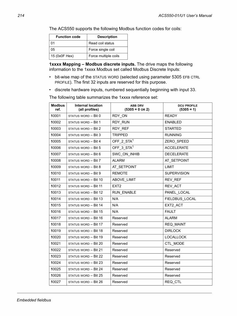
214 ACS550-01/U1 User’s Manual
The ACS550 supports the following Modbus function codes for coils:
1xxxx Mapping – Modbus discrete inputs. The drive maps the following information to the 1xxxx Modbus set called Modbus Discrete Inputs:
• bit-wise map of the STATUS WORD (selected using parameter 5305 EFB CTRL PROFILE). The first 32 inputs are reserved for this purpose.
• discrete hardware inputs, numbered sequentially beginning with input 33.
The following table summarizes the 1xxxx reference set:
Function code Description
01 Read coil status
05 Force single coil
15 (0x0F Hex) Force multiple coils
Modbus ref.
Internal location(all profiles)
ABB DRV(5305 = 0 OR 2)
DCU PROFILE(5305 = 1)
10001 STATUS WORD – Bit 0 RDY_ON READY
10002 STATUS WORD – Bit 1 RDY_RUN ENABLED
10003 STATUS WORD – Bit 2 RDY_REF STARTED
10004 STATUS WORD – Bit 3 TRIPPED RUNNING
10005 STATUS WORD – Bit 4 OFF_2_STA1 ZERO_SPEED
10006 STATUS WORD – Bit 5 OFF_3_STA1 ACCELERATE
10007 STATUS WORD – Bit 6 SWC_ON_INHIB DECELERATE
10008 STATUS WORD – Bit 7 ALARM AT_SETPOINT
10009 STATUS WORD – Bit 8 AT_SETPOINT LIMIT
10010 STATUS WORD – Bit 9 REMOTE SUPERVISION
10011 STATUS WORD – Bit 10 ABOVE_LIMIT REV_REF
10012 STATUS WORD – Bit 11 EXT2 REV_ACT
10013 STATUS WORD – Bit 12 RUN_ENABLE PANEL_LOCAL
10014 STATUS WORD – Bit 13 N/A FIELDBUS_LOCAL
10015 STATUS WORD – Bit 14 N/A EXT2_ACT
10016 STATUS WORD – Bit 15 N/A FAULT
10017 STATUS WORD – Bit 16 Reserved ALARM
10018 STATUS WORD – Bit 17 Reserved REQ_MAINT
10019 STATUS WORD – Bit 18 Reserved DIRLOCK
10020 STATUS WORD – Bit 19 Reserved LOCALLOCK
10021 STATUS WORD – Bit 20 Reserved CTL_MODE
10022 STATUS WORD – Bit 21 Reserved Reserved
10023 STATUS WORD – Bit 22 Reserved Reserved
10024 STATUS WORD – Bit 23 Reserved Reserved
10025 STATUS WORD – Bit 24 Reserved Reserved
10026 STATUS WORD – Bit 25 Reserved Reserved
10027 STATUS WORD – Bit 26 Reserved REQ_CTL
Embedded fieldbus
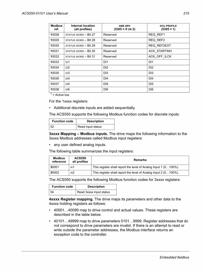
ACS550-01/U1 User’s Manual 215
For the 1xxxx registers:
• Additional discrete inputs are added sequentially.
The ACS550 supports the following Modbus function codes for discrete inputs:
3xxxx Mapping – Modbus inputs. The drive maps the following information to the 3xxxx Modbus addresses called Modbus input registers:
• any user defined analog inputs.
The following table summarizes the input registers:
The ACS550 supports the following Modbus function codes for 3xxxx registers:
4xxxx Register mapping. The drive maps its parameters and other data to the 4xxxx holding registers as follows:
• 40001…40099 map to drive control and actual values. These registers are described in the table below.
• 40101…49999 map to drive parameters 0101…9999. Register addresses that do not correspond to drive parameters are invalid. If there is an attempt to read or write outside the parameter addresses, the Modbus interface returns an exception code to the controller.
10028 STATUS WORD – Bit 27 Reserved REQ_REF1
10029 STATUS WORD – Bit 28 Reserved REQ_REF2
10030 STATUS WORD – Bit 29 Reserved REQ_REF2EXT
10031 STATUS WORD – Bit 30 Reserved ACK_STARTINH
10032 STATUS WORD – Bit 31 Reserved ACK_OFF_ILCK
10033 DI1 DI1 DI1
10034 DI2 DI2 DI2
10035 DI3 DI3 DI3
10036 DI4 DI4 DI4
10037 DI5 DI5 DI5
10038 DI6 DI6 DI61 = Active low
Function code Description
02 Read input status
Modbus reference
ACS550all profiles Remarks
30001 AI1 This register shall report the level of Analog Input 1 (0…100%).
30002 AI2 This register shall report the level of Analog Input 2 (0…100%).
Function code Description
04 Read 3xxxx input status
Modbus ref.
Internal location(all profiles)
ABB DRV(5305 = 0 OR 2)
DCU PROFILE(5305 = 1)
Embedded fieldbus
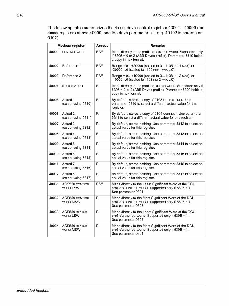
216 ACS550-01/U1 User’s Manual
The following table summarizes the 4xxxx drive control registers 40001…40099 (for 4xxxx registers above 40099, see the drive parameter list, e.g. 40102 is parameter 0102):
Modbus register Access Remarks
40001 CONTROL WORD R/W Maps directly to the profile‘S CONTROL WORD. Supported only if 5305 = 0 or 2 (ABB Drives profile). Parameter 5319 holds a copy in hex format.
40002 Reference 1 R/W Range = 0…+20000 (scaled to 0…1105 REF1 MAX), or -20000…0 (scaled to 1105 REF1 MAX…0).
40003 Reference 2 R/W Range = 0…+10000 (scaled to 0…1108 REF2 MAX), or -10000…0 (scaled to 1108 REF2 MAX…0).
40004 STATUS WORD R Maps directly to the profile‘S STATUS WORD. Supported only if 5305 = 0 or 2 (ABB Drives profile). Parameter 5320 holds a copy in hex format.
40005 Actual 1 (select using 5310)
R By default, stores a copy of 0103 OUTPUT FREQ. Use parameter 5310 to select a different actual value for this register.
40006 Actual 2(select using 5311)
R By default, stores a copy of 0104 CURRENT. Use parameter 5311 to select a different actual value for this register.
40007 Actual 3 (select using 5312)
R By default, stores nothing. Use parameter 5312 to select an actual value for this register.
40008 Actual 4(select using 5313)
R By default, stores nothing. Use parameter 5313 to select an actual value for this register.
40009 Actual 5 (select using 5314)
R By default, stores nothing. Use parameter 5314 to select an actual value for this register.
40010 Actual 6 (select using 5315)
R By default, stores nothing. Use parameter 5315 to select an actual value for this register.
40011 Actual 7 (select using 5316)
R By default, stores nothing. Use parameter 5316 to select an actual value for this register.
40012 Actual 8 (select using 5317)
R By default, stores nothing. Use parameter 5317 to select an actual value for this register.
40031 ACS550 CONTROL WORD LSW
R/W Maps directly to the Least Significant Word of the DCU profile‘s CONTROL WORD. Supported only if 5305 = 1. See parameter 0301.
40032 ACS550 CONTROL WORD MSW
R Maps directly to the Most Significant Word of the DCU profile‘s CONTROL WORD. Supported only if 5305 = 1. See parameter 0302.
40033 ACS550 STATUS WORD LSW
R Maps directly to the Least Significant Word of the DCU profile‘s STATUS WORD. Supported only if 5305 = 1. See parameter 0303.
40034 ACS550 STATUS WORD MSW
R Maps directly to the Most Significant Word of the DCU profile‘s STATUS WORD. Supported only if 5305 = 1. See parameter 0304.
Embedded fieldbus
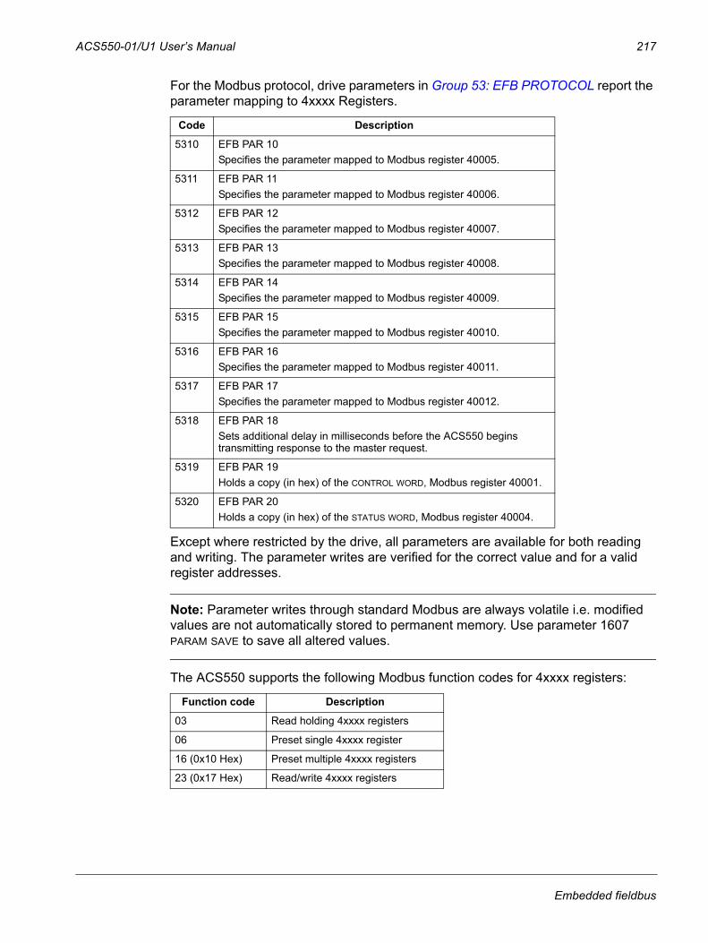
ACS550-01/U1 User’s Manual 217
For the Modbus protocol, drive parameters in Group 53: EFB PROTOCOL report the parameter mapping to 4xxxx Registers.
Except where restricted by the drive, all parameters are available for both reading and writing. The parameter writes are verified for the correct value and for a valid register addresses.
Note: Parameter writes through standard Modbus are always volatile i.e. modified values are not automatically stored to permanent memory. Use parameter 1607 PARAM SAVE to save all altered values.
The ACS550 supports the following Modbus function codes for 4xxxx registers:
Code Description
5310 EFB PAR 10Specifies the parameter mapped to Modbus register 40005.
5311 EFB PAR 11Specifies the parameter mapped to Modbus register 40006.
5312 EFB PAR 12Specifies the parameter mapped to Modbus register 40007.
5313 EFB PAR 13Specifies the parameter mapped to Modbus register 40008.
5314 EFB PAR 14Specifies the parameter mapped to Modbus register 40009.
5315 EFB PAR 15Specifies the parameter mapped to Modbus register 40010.
5316 EFB PAR 16Specifies the parameter mapped to Modbus register 40011.
5317 EFB PAR 17Specifies the parameter mapped to Modbus register 40012.
5318 EFB PAR 18Sets additional delay in milliseconds before the ACS550 begins transmitting response to the master request.
5319 EFB PAR 19Holds a copy (in hex) of the CONTROL WORD, Modbus register 40001.
5320 EFB PAR 20Holds a copy (in hex) of the STATUS WORD, Modbus register 40004.
Function code Description
03 Read holding 4xxxx registers
06 Preset single 4xxxx register
16 (0x10 Hex) Preset multiple 4xxxx registers
23 (0x17 Hex) Read/write 4xxxx registers
Embedded fieldbus
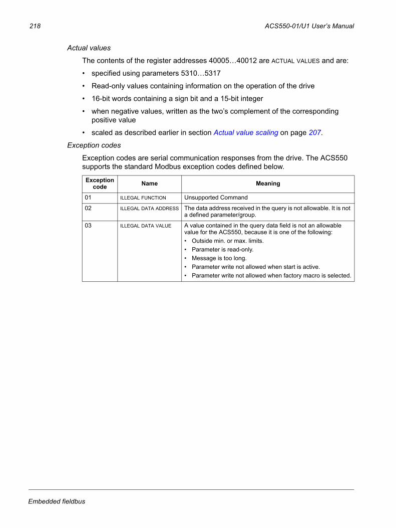
218 ACS550-01/U1 User’s Manual
Actual values
The contents of the register addresses 40005…40012 are ACTUAL VALUES and are:
• specified using parameters 5310…5317
• Read-only values containing information on the operation of the drive
• 16-bit words containing a sign bit and a 15-bit integer
• when negative values, written as the two’s complement of the corresponding positive value
• scaled as described earlier in section Actual value scaling on page 207.
Exception codes
Exception codes are serial communication responses from the drive. The ACS550 supports the standard Modbus exception codes defined below.
Exception code Name Meaning
01 ILLEGAL FUNCTION Unsupported Command
02 ILLEGAL DATA ADDRESS The data address received in the query is not allowable. It is not a defined parameter/group.
03 ILLEGAL DATA VALUE A value contained in the query data field is not an allowable value for the ACS550, because it is one of the following:• Outside min. or max. limits.• Parameter is read-only.• Message is too long.• Parameter write not allowed when start is active.• Parameter write not allowed when factory macro is selected.
Embedded fieldbus
ACS550-01/U1 User’s Manual 219
ABB control profiles technical data
OverviewABB Drives profile
The ABB Drives profile provides a standard profile that can be used on multiple protocols, including Modbus and the protocols available on the FBA module. Two implementations of the ABB Drives profile are available:
• ABB DRV FULL – This implementation standardizes the control interface with ACS600 and ACS800 drives.
• ABB DRV LIM – This implementation standardizes the control interface with ACS400 drives. This implementation does not support two control word bits supported by ABB DRV FULL.
Except as noted, the following “ABB Drives Profile” descriptions apply to both implementations.
DCU profile
The DCU profile extends the control and status interface to 32 bits. It is the internal interface between the main drive application and the embedded fieldbus environment.
Control WordThe CONTROL WORD is the principal means for controlling the drive from a fieldbus system. The fieldbus master station sends the CONTROL WORD to the drive. The drive switches between states according to the bit-coded instructions in the CONTROL WORD. Using the CONTROL WORD requires that:
• The drive is in remote (REM) control.
• The serial communication channel is defined as the source for controlling commands (set using parameters such as 1001 EXT1 COMMANDS, 1002 EXT2 COMMANDS and 1102 EXT1/EXT2 SEL).
• The serial communication channel used is configured to use an ABB control profile. For example, to use the control profile ABB DRV FULL requires both parameter 9802 COMM PROT SEL = 1 (STD MODBUS) and parameter 5305 EFB CTRL PROFILE = 2 (ABB DRV FULL).
Embedded fieldbus
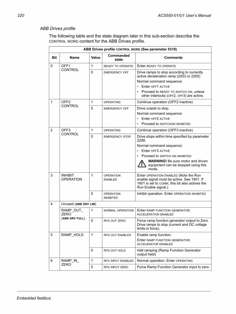
220 ACS550-01/U1 User’s Manual
ABB Drives profile
The following table and the state diagram later in this sub-section describe the CONTROL WORD content for the ABB Drives profile.
ABB Drives profile CONTROL WORD (See parameter 5319)
Bit Name Value Commanded state Comments
0 OFF1 CONTROL
1 READY TO OPERATE Enter READY TO OPERATE
0 EMERGENCY OFF Drive ramps to stop according to currently active deceleration ramp (2203 or 2205)Normal command sequence:• Enter OFF1 ACTIVE
• Proceed to READY TO SWITCH ON, unless other interlocks (OFF2, OFF3) are active.
1 OFF2 CONTROL
1 OPERATING Continue operation (OFF2 inactive)
0 EMERGENCY OFF Drive coasts to stop. Normal command sequence:• Enter OFF2 ACTIVE
• Proceed to SWITCHON INHIBITED
2 OFF3 CONTROL
1 OPERATING Continue operation (OFF3 inactive)
0 EMERGENCY STOP Drive stops within time specified by parameter 2208. Normal command sequence:• Enter OFF3 ACTIVE
• Proceed to SWITCH ON INHIBITED
WARNING! Be sure motor and driven equipment can be stopped using this mode.
3 INHIBIT OPERATION
1 OPERATION ENABLED
Enter OPERATION ENABLED (Note the Run enable signal must be active. See 1601. If 1601 is set to COMM, this bit also actives the Run Enable signal.)
0 OPERATION INHIBITED
Inhibit operation. Enter OPERATION INHIBITED
4 Unused (ABB DRV LIM)
RAMP_OUT_ZERO (ABB DRV FULL)
1 NORMAL OPERATION Enter RAMP FUNCTION GENERATOR: ACCELERATION ENABLED
0 RFG OUT ZERO Force ramp function generator output to Zero. Drive ramps to stop (current and DC voltage limits in force).
5 RAMP_HOLD 1 RFG OUT ENABLED Enable ramp function.Enter RAMP FUNCTION GENERATOR: ACCELERATOR ENABLED
0 RFG OUT HOLD Halt ramping (Ramp Function Generator output held)
6 RAMP_IN_ZERO
1 RFG INPUT ENABLED Normal operation. Enter OPERATING
0 RFG INPUT ZERO Force Ramp Function Generator input to zero.
Embedded fieldbus
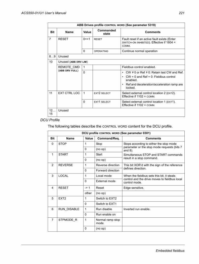
ACS550-01/U1 User’s Manual 221
DCU Profile
The following tables describe the CONTROL WORD content for the DCU profile.
7 RESET 0=>1 RESET Fault reset if an active fault exists (Enter SWITCH-ON INHIBITED). Effective if 1604 = COMM.
0 OPERATING Continue normal operation
8…9 Unused
10 Unused (ABB DRV LIM)
REMOTE_CMD (ABB DRV FULL)
1 Fieldbus control enabled.
0 • CW 0 or Ref 0: Retain last CW and Ref.• CW = 0 and Ref = 0: Fieldbus control
enabled.• Ref and deceleration/acceleration ramp are
locked.
11 EXT CTRL LOC 1 EXT2 SELECT Select external control location 2 (EXT2). Effective if 1102 = COMM.
0 EXT1 SELECT Select external control location 1 (EXT1). Effective if 1102 = COMM.
12…15
Unused
DCU profile CONTROL WORD (See parameter 0301)
Bit Name Value Command/Req. Comments
0 STOP 1 Stop Stops according to either the stop mode parameter or the stop mode requests (bits 7 and 8).Simultaneous STOP and START commands result in a stop command.
0 (no op)
1 START 1 Start
0 (no op)
2 REVERSE 1 Reverse direction This bit XOR’d with the sign of the reference defines direction.
0 Forward direction
3 LOCAL 1 Local mode When the fieldbus sets this bit, it steals control and the drive moves to fieldbus local control mode.0 External mode
4 RESET -> 1 Reset Edge sensitive.
other (no op)
5 EXT2 1 Switch to EXT2
0 Switch to EXT1
6 RUN_DISABLE 1 Run disable Inverted run enable.
0 Run enable on
7 STPMODE_R 1 Normal ramp stop mode
0 (no op)
ABB Drives profile CONTROL WORD (See parameter 5319)
Bit Name Value Commanded state Comments
=/ =/
Embedded fieldbus
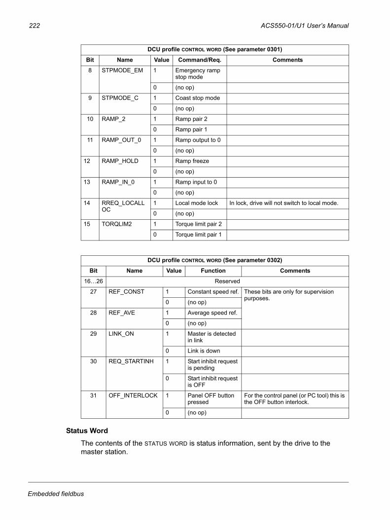
222 ACS550-01/U1 User’s Manual
Status WordThe contents of the STATUS WORD is status information, sent by the drive to the master station.
8 STPMODE_EM 1 Emergency ramp stop mode
0 (no op)
9 STPMODE_C 1 Coast stop mode
0 (no op)
10 RAMP_2 1 Ramp pair 2
0 Ramp pair 1
11 RAMP_OUT_0 1 Ramp output to 0
0 (no op)
12 RAMP_HOLD 1 Ramp freeze
0 (no op)
13 RAMP_IN_0 1 Ramp input to 0
0 (no op)
14 RREQ_LOCALLOC
1 Local mode lock In lock, drive will not switch to local mode.
0 (no op)
15 TORQLIM2 1 Torque limit pair 2
0 Torque limit pair 1
DCU profile CONTROL WORD (See parameter 0302)
Bit Name Value Function Comments
16…26 Reserved
27 REF_CONST 1 Constant speed ref. These bits are only for supervision purposes.
0 (no op)
28 REF_AVE 1 Average speed ref.
0 (no op)
29 LINK_ON 1 Master is detected in link
0 Link is down
30 REQ_STARTINH 1 Start inhibit request is pending
0 Start inhibit request is OFF
31 OFF_INTERLOCK 1 Panel OFF button pressed
For the control panel (or PC tool) this is the OFF button interlock.
0 (no op)
DCU profile CONTROL WORD (See parameter 0301)
Bit Name Value Command/Req. Comments
Embedded fieldbus
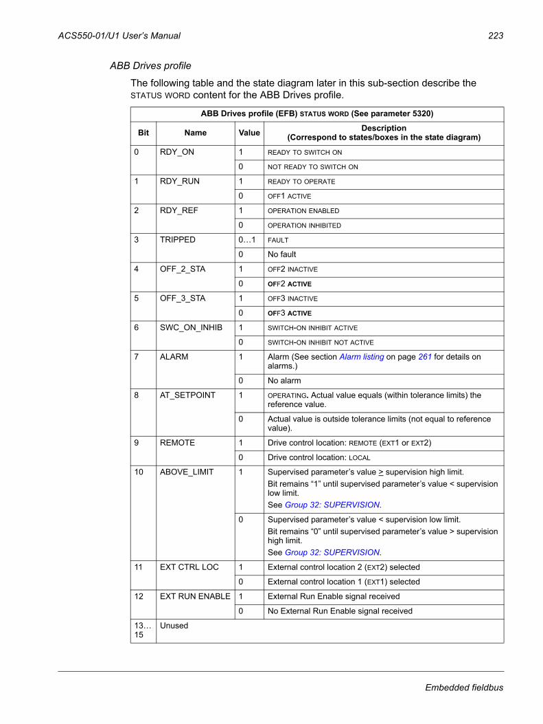
ACS550-01/U1 User’s Manual 223
ABB Drives profile
The following table and the state diagram later in this sub-section describe the STATUS WORD content for the ABB Drives profile.
ABB Drives profile (EFB) STATUS WORD (See parameter 5320)
Bit Name Value Description (Correspond to states/boxes in the state diagram)
0 RDY_ON 1 READY TO SWITCH ON
0 NOT READY TO SWITCH ON
1 RDY_RUN 1 READY TO OPERATE
0 OFF1 ACTIVE
2 RDY_REF 1 OPERATION ENABLED
0 OPERATION INHIBITED
3 TRIPPED 0…1 FAULT
0 No fault
4 OFF_2_STA 1 OFF2 INACTIVE
0 OFF2 ACTIVE
5 OFF_3_STA 1 OFF3 INACTIVE
0 OFF3 ACTIVE
6 SWC_ON_INHIB 1 SWITCH-ON INHIBIT ACTIVE
0 SWITCH-ON INHIBIT NOT ACTIVE
7 ALARM 1 Alarm (See section Alarm listing on page 261 for details on alarms.)
0 No alarm
8 AT_SETPOINT 1 OPERATING. Actual value equals (within tolerance limits) the reference value.
0 Actual value is outside tolerance limits (not equal to reference value).
9 REMOTE 1 Drive control location: REMOTE (EXT1 or EXT2)
0 Drive control location: LOCAL
10 ABOVE_LIMIT 1 Supervised parameter’s value > supervision high limit.Bit remains “1” until supervised parameter’s value < supervision low limit.See Group 32: SUPERVISION.
0 Supervised parameter’s value < supervision low limit.Bit remains “0” until supervised parameter’s value > supervision high limit.See Group 32: SUPERVISION.
11 EXT CTRL LOC 1 External control location 2 (EXT2) selected
0 External control location 1 (EXT1) selected
12 EXT RUN ENABLE 1 External Run Enable signal received
0 No External Run Enable signal received
13… 15
Unused
Embedded fieldbus
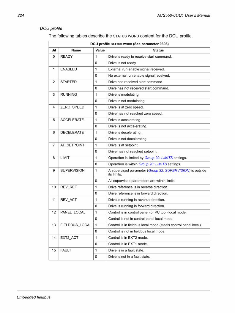
224 ACS550-01/U1 User’s Manual
DCU profile
The following tables describe the STATUS WORD content for the DCU profile.
DCU profile STATUS WORD (See parameter 0303)
Bit Name Value Status
0 READY 1 Drive is ready to receive start command.
0 Drive is not ready.
1 ENABLED 1 External run enable signal received.
0 No external run enable signal received.
2 STARTED 1 Drive has received start command.
0 Drive has not received start command.
3 RUNNING 1 Drive is modulating.
0 Drive is not modulating.
4 ZERO_SPEED 1 Drive is at zero speed.
0 Drive has not reached zero speed.
5 ACCELERATE 1 Drive is accelerating.
0 Drive is not accelerating.
6 DECELERATE 1 Drive is decelerating.
0 Drive is not decelerating.
7 AT_SETPOINT 1 Drive is at setpoint.
0 Drive has not reached setpoint.
8 LIMIT 1 Operation is limited by Group 20: LIMITS settings.
0 Operation is within Group 20: LIMITS settings.
9 SUPERVISION 1 A supervised parameter (Group 32: SUPERVISION) is outside its limits.
0 All supervised parameters are within limits.
10 REV_REF 1 Drive reference is in reverse direction.
0 Drive reference is in forward direction.
11 REV_ACT 1 Drive is running in reverse direction.
0 Drive is running in forward direction.
12 PANEL_LOCAL 1 Control is in control panel (or PC tool) local mode.
0 Control is not in control panel local mode.
13 FIELDBUS_LOCAL 1 Control is in fieldbus local mode (steals control panel local).
0 Control is not in fieldbus local mode.
14 EXT2_ACT 1 Control is in EXT2 mode.
0 Control is in EXT1 mode.
15 FAULT 1 Drive is in a fault state.
0 Drive is not in a fault state.
Embedded fieldbus
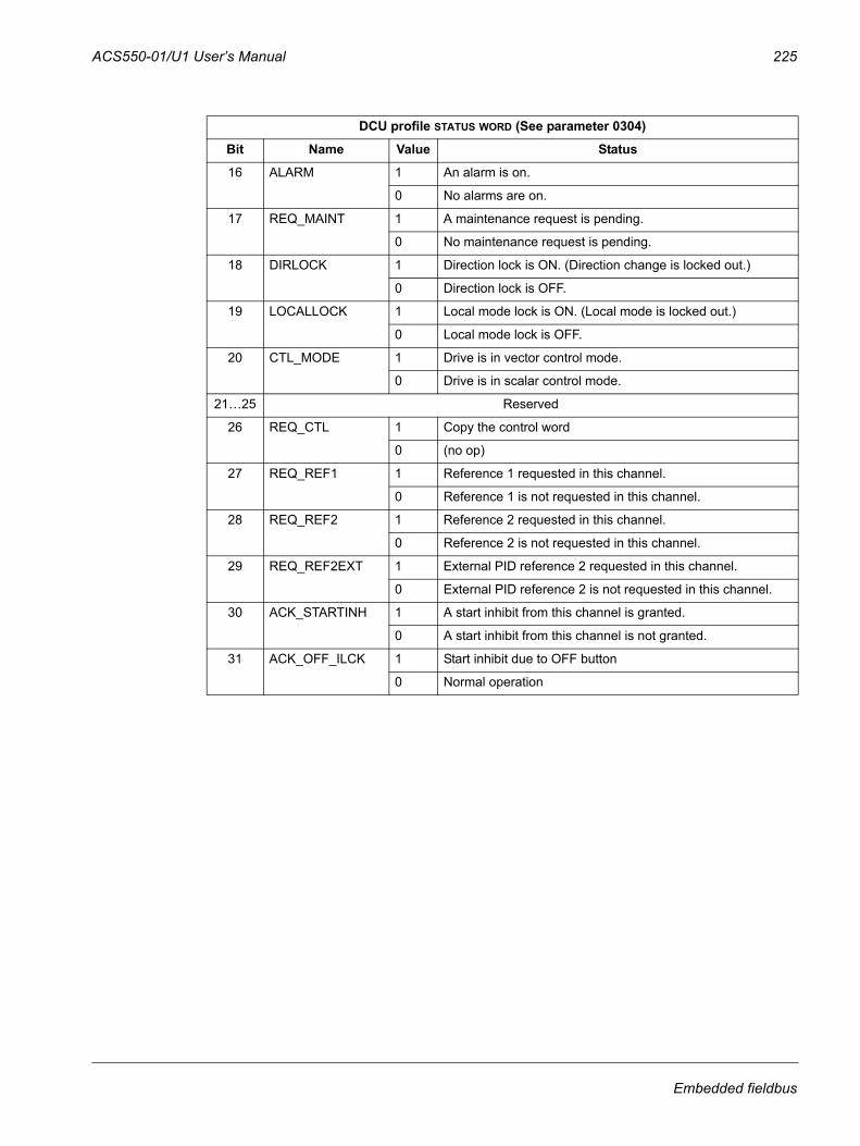
ACS550-01/U1 User’s Manual 225
DCU profile STATUS WORD (See parameter 0304)
Bit Name Value Status
16 ALARM 1 An alarm is on.
0 No alarms are on.
17 REQ_MAINT 1 A maintenance request is pending.
0 No maintenance request is pending.
18 DIRLOCK 1 Direction lock is ON. (Direction change is locked out.)
0 Direction lock is OFF.
19 LOCALLOCK 1 Local mode lock is ON. (Local mode is locked out.)
0 Local mode lock is OFF.
20 CTL_MODE 1 Drive is in vector control mode.
0 Drive is in scalar control mode.
21…25 Reserved
26 REQ_CTL 1 Copy the control word
0 (no op)
27 REQ_REF1 1 Reference 1 requested in this channel.
0 Reference 1 is not requested in this channel.
28 REQ_REF2 1 Reference 2 requested in this channel.
0 Reference 2 is not requested in this channel.
29 REQ_REF2EXT 1 External PID reference 2 requested in this channel.
0 External PID reference 2 is not requested in this channel.
30 ACK_STARTINH 1 A start inhibit from this channel is granted.
0 A start inhibit from this channel is not granted.
31 ACK_OFF_ILCK 1 Start inhibit due to OFF button
0 Normal operation
Embedded fieldbus
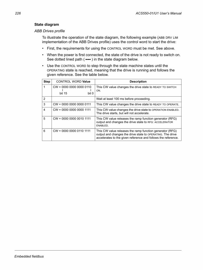
226 ACS550-01/U1 User’s Manual
State diagramABB Drives profile
To illustrate the operation of the state diagram, the following example (ABB DRV LIM implementation of the ABB Drives profile) uses the control word to start the drive:
• First, the requirements for using the CONTROL WORD must be met. See above.
• When the power is first connected, the state of the drive is not ready to switch on. See dotted lined path ( ) in the state diagram below.
• Use the CONTROL WORD to step through the state machine states until the OPERATING state is reached, meaning that the drive is running and follows the given reference. See the table below.
Step CONTROL WORD Value Description
1 CW = 0000 0000 0000 0110 This CW value changes the drive state to READY TO SWITCH ON.
2 Wait at least 100 ms before proceeding.
3 CW = 0000 0000 0000 0111 This CW value changes the drive state to READY TO OPERATE.
4 CW = 0000 0000 0000 1111 This CW value changes the drive state to OPERATION ENABLED. The drive starts, but will not accelerate.
5 CW = 0000 0000 0010 1111 This CW value releases the ramp function generator (RFG) output and changes the drive state to RFG: ACCELERATOR ENABLED.
6 CW = 0000 0000 0110 1111 This CW value releases the ramp function generator (RFG) output and changes the drive state to OPERATING. The drive accelerates to the given reference and follows the reference.
bit 0bit 15
Embedded fieldbus
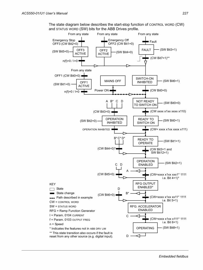
ACS550-01/U1 User’s Manual 227
The state diagram below describes the start-stop function of CONTROL WORD (CW) and STATUS WORD (SW) bits for the ABB Drives profile.
(CW xxxx x1xx xxxx x110)
MAINS OFF
Power ON (CW Bit0=0)
(SW Bit6=1)
(SW Bit0=0)
From any state
n(f)=0 / I=0
OFF1 (CW Bit0=0)
A C D
(CW Bit3=0)
(SW Bit2=0) (SW Bit0=1)
(CW= xxxx x1xx xxxx x111)
(SW Bit1=1)
(CW Bit3=1 and(CW Bit4=0)*
n(f)=0 / I=0
From any state
SWITCH-ONINHIBITED
NOT READYTO SWITCH ON
OPERATIONINHIBITED
READY TOSWITCH ON
READY TOOPERATE
RFG OUTPUTENABLED*
C* D*
From any state
Emergency OffOFF2 (CW Bit1=0)
(SW Bit4=0)OFF2ACTIVE
From any state
Fault
(SW Bit3=1)FAULT
(CW Bit7=1)**
(SW Bit5=0)
Emergency StopOFF3 (CW Bit2=0)
SW Bit12=1)
RFG: ACCELERATORENABLED
(CW=xxxx x1xx xx11* 1111(CW Bit6=0)
C(CW=xxxx x1xx x111* 1111
(SW Bit8=1)
D
B*D
OPERATING
OFF3ACTIVE
KEYStateState changePath described in example
CW = CONTROL WORD
SW = STATUS WORD
RFG = Ramp Function GeneratorI = Param. 0104 CURRENT
f = Param. 0103 OUTPUT FREQ
n = Speed* Indicates the features not in ABB DRV LIM
** This state transition also occurs if the fault is reset from any other source (e.g. digital input).
(SW Bit2=1)OPERATIONENABLED
(CW=xxxx x1xx xxx1* 1111A
(CW Bit5=0)
C D
B*
B*
(SW Bit1=0) OFF1ACTIVE
OPERATION INHIBITED
i.e. Bit 4=1)*
i.e. Bit 5=1)
i.e. Bit 6=1)
Embedded fieldbus
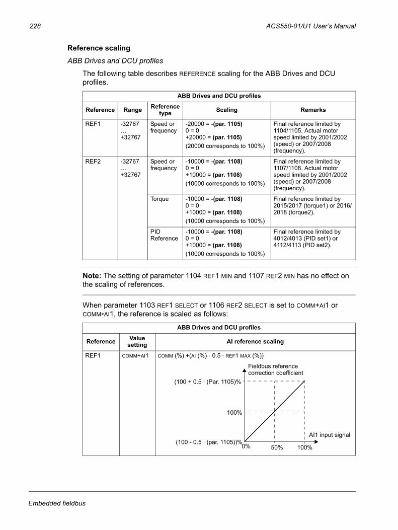
228 ACS550-01/U1 User’s Manual
Reference scalingABB Drives and DCU profiles
The following table describes REFERENCE scaling for the ABB Drives and DCU profiles.
Note: The setting of parameter 1104 REF1 MIN and 1107 REF2 MIN has no effect on the scaling of references.
When parameter 1103 REF1 SELECT or 1106 REF2 SELECT is set to COMM+AI1 or COMM*AI1, the reference is scaled as follows:
ABB Drives and DCU profiles
Reference Range Reference type Scaling Remarks
REF1 -32767…+32767
Speed or frequency
-20000 = -(par. 1105)0 = 0+20000 = (par. 1105)(20000 corresponds to 100%)
Final reference limited by 1104/1105. Actual motor speed limited by 2001/2002 (speed) or 2007/2008 (frequency).
REF2 -32767…+32767
Speed or frequency
-10000 = -(par. 1108)0 = 0+10000 = (par. 1108)(10000 corresponds to 100%)
Final reference limited by 1107/1108. Actual motor speed limited by 2001/2002 (speed) or 2007/2008 (frequency).
Torque -10000 = -(par. 1108)0 = 0+10000 = (par. 1108)(10000 corresponds to 100%)
Final reference limited by 2015/2017 (torque1) or 2016/2018 (torque2).
PID Reference
-10000 = -(par. 1108)0 = 0+10000 = (par. 1108)(10000 corresponds to 100%)
Final reference limited by 4012/4013 (PID set1) or 4112/4113 (PID set2).
ABB Drives and DCU profiles
Reference Value setting AI reference scaling
REF1 COMM+AI1 COMM (%) +(AI (%) - 0.5 · REF1 MAX (%))
0% 50%
(100 + 0.5 · (Par. 1105)%
(100 - 0.5 · (par. 1105))%
100%
100%
AI1 input signal
Fieldbus referencecorrection coefficient
Embedded fieldbus
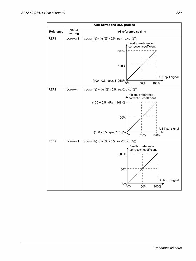
ACS550-01/U1 User’s Manual 229
REF1 COMM*AI1 COMM (%) · (AI (%) / 0.5 · REF1 MAX (%))
REF2 COMM+AI1 COMM (%) + (AI (%) - 0.5 · REF2 MAX (%))
REF2 COMM*AI1 COMM (%) · (AI (%) / 0.5 · REF2 MAX (%))
ABB Drives and DCU profiles
Reference Value setting AI reference scaling
0% 50%
200%
(100 - 0.5 · (par. 1105))%
100%
100%
AI1 input signal
Fieldbus referencecorrection coefficient
0% 50%
(100 + 0.5 · (Par. 1108)%
(100 - 0.5 · (par. 1108)%
100%
100%
AI1 input signal
Fieldbus referencecorrection coefficient
0% 50%
200%
0%
100%
100%
AI1input signal
Fieldbus referencecorrection coefficient
Embedded fieldbus
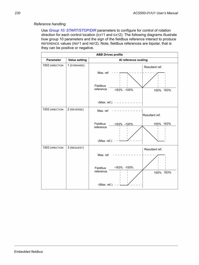
230 ACS550-01/U1 User’s Manual
Reference handling
Use Group 10: START/STOP/DIR parameters to configure for control of rotation direction for each control location (EXT1 and EXT2). The following diagrams illustrate how group 10 parameters and the sign of the fieldbus reference interact to produce REFERENCE values (REF1 and REF2). Note, fieldbus references are bipolar, that is they can be positive or negative.
ABB Drives profile
Parameter Value setting AI reference scaling
1003 DIRECTION 1 (FORWARD)
1003 DIRECTION 2 (REVERSE)
1003 DIRECTION 3 (REQUEST)
100%
Max. ref
-100%-163% 163%
-(Max. ref.)
Fieldbus
Resultant ref.
reference
100%
Max. ref
-100%-163% 163%
-(Max. ref.)
Fieldbus
Resultant ref.
reference
100%
Max. ref
-100%-163%163%
-(Max. ref.)
Fieldbus
Resultant ref.
reference
Embedded fieldbus
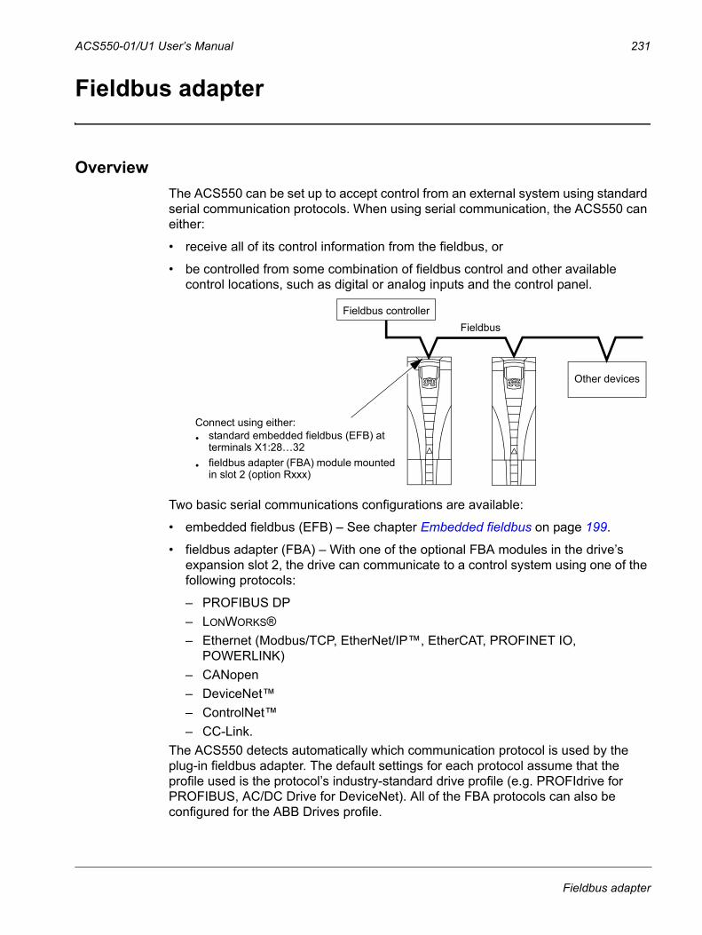
ACS550-01/U1 User’s Manual 231
Fieldbus adapter
OverviewThe ACS550 can be set up to accept control from an external system using standard serial communication protocols. When using serial communication, the ACS550 can either:
• receive all of its control information from the fieldbus, or
• be controlled from some combination of fieldbus control and other available control locations, such as digital or analog inputs and the control panel.
Two basic serial communications configurations are available:
• embedded fieldbus (EFB) – See chapter Embedded fieldbus on page 199.
• fieldbus adapter (FBA) – With one of the optional FBA modules in the drive’s expansion slot 2, the drive can communicate to a control system using one of the following protocols:
– PROFIBUS DP– LONWORKS®– Ethernet (Modbus/TCP, EtherNet/IP™, EtherCAT, PROFINET IO,
POWERLINK)– CANopen– DeviceNet™– ControlNet™– CC-Link.
The ACS550 detects automatically which communication protocol is used by the plug-in fieldbus adapter. The default settings for each protocol assume that the profile used is the protocol’s industry-standard drive profile (e.g. PROFIdrive for PROFIBUS, AC/DC Drive for DeviceNet). All of the FBA protocols can also be configured for the ABB Drives profile.
Connect using either:• standard embedded fieldbus (EFB) at
terminals X1:28…32
• fieldbus adapter (FBA) module mounted in slot 2 (option Rxxx)
FieldbusFieldbus controller
Other devices
Fieldbus adapter
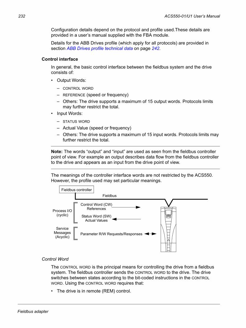
232 ACS550-01/U1 User’s Manual
Configuration details depend on the protocol and profile used.These details are provided in a user’s manual supplied with the FBA module.
Details for the ABB Drives profile (which apply for all protocols) are provided in section ABB Drives profile technical data on page 242.
Control interfaceIn general, the basic control interface between the fieldbus system and the drive consists of:
• Output Words:
– CONTROL WORD – REFERENCE (speed or frequency)– Others: The drive supports a maximum of 15 output words. Protocols limits
may further restrict the total.• Input Words:
– STATUS WORD
– Actual Value (speed or frequency)– Others: The drive supports a maximum of 15 input words. Protocols limits may
further restrict the total.
Note: The words “output” and “input” are used as seen from the fieldbus controller point of view. For example an output describes data flow from the fieldbus controller to the drive and appears as an input from the drive point of view.
The meanings of the controller interface words are not restricted by the ACS550. However, the profile used may set particular meanings.
Control Word
The CONTROL WORD is the principal means for controlling the drive from a fieldbus system. The fieldbus controller sends the CONTROL WORD to the drive. The drive switches between states according to the bit-coded instructions in the CONTROL WORD. Using the CONTROL WORD requires that:
• The drive is in remote (REM) control.
FieldbusFieldbus controller
Control Word (CW)References
Status Word (SW)Actual Values
Parameter R/W Requests/Responses
Process I/O
ServiceMessages(Acyclic)
(cyclic)
Fieldbus adapter
ACS550-01/U1 User’s Manual 233
• The serial communication channel is defined as the source for controlling commands from EXT1 (set using parameters 1001 EXT1 COMMANDS and 1102 EXT1/EXT2 SEL).
• The external plug-in fieldbus adapter is activated:
– Parameter 9802 COMM PROT SEL = 4 (EXT FBA).– The external plug-in fieldbus adapter is configured to use the drive profile
mode or drive profile objects.The content of the CONTROL WORD depends on the protocol/profile used. See the user’s manual provided with the FBA module and/or section ABB Drives profile technical data on page 242.
Status Word
The STATUS WORD is a 16-bit word containing status information, sent by the drive to the fieldbus controller. The content of the STATUS WORD depends on the protocol/profile used. See the user’s manual provided with the FBA module and/or section ABB Drives profile technical data on page 242.
Reference
The contents of each REFERENCE word:
• can be used, as speed or frequency reference
• is a 16-bit word comprised of a sign bit and a 15-bit integer
• Negative references (indicating reversed rotation direction) are indicated by the two’s complement of the corresponding positive reference value.
The use of a second reference (REF2) is supported only when a protocol is configured for the ABB Drives profile.
Reference scaling is fieldbus type specific. See the user’s manual provided with the FBA module and/or the following sections as appropriate:
• Reference scaling on page 246 (ABB Drives profile technical data)
• Reference scaling on page 250 (Generic profile technical data).
Actual Values
Actual Values are 16-bit words containing information on selected operations of the drive. Drive Actual Values (for example, Group 10: START/STOP/DIR parameters) can be mapped to Input Words using Group 51: EXT COMM MODULE parameters (protocol-dependent, but typically parameters 5104…5126).
PlanningNetwork planning should address the following questions:
• What types and quantities of devices must be connected to the network?
• What control information must be sent down to the drives?
• What feedback information must be sent from the drives to the controlling system?
Fieldbus adapter
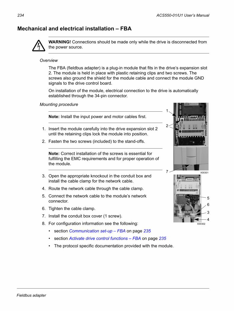
234 ACS550-01/U1 User’s Manual
Mechanical and electrical installation – FBA
WARNING! Connections should be made only while the drive is disconnected from the power source.
Overview
The FBA (fieldbus adapter) is a plug-in module that fits in the drive’s expansion slot 2. The module is held in place with plastic retaining clips and two screws. The screws also ground the shield for the module cable and connect the module GND signals to the drive control board.
On installation of the module, electrical connection to the drive is automatically established through the 34-pin connector.
Mounting procedure
Note: Install the input power and motor cables first.
1. Insert the module carefully into the drive expansion slot 2 until the retaining clips lock the module into position.
2. Fasten the two screws (included) to the stand-offs.
Note: Correct installation of the screws is essential for fulfilling the EMC requirements and for proper operation of the module.
3. Open the appropriate knockout in the conduit box and install the cable clamp for the network cable.
4. Route the network cable through the cable clamp.
5. Connect the network cable to the module’s network connector.
6. Tighten the cable clamp.
7. Install the conduit box cover (1 screw).
8. For configuration information see the following:
• section Communication set-up – FBA on page 235
• section Activate drive control functions – FBA on page 235
• The protocol specific documentation provided with the module.
1
2
7 X00301
5
4
6
3
X00302
Fieldbus adapter
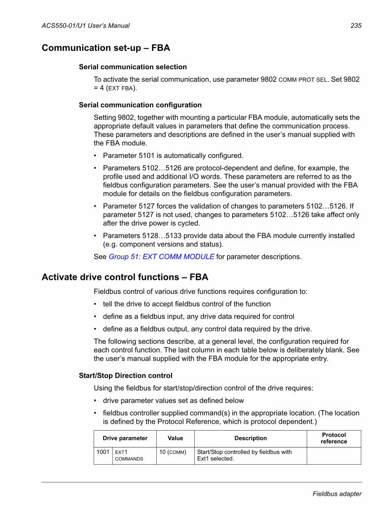
ACS550-01/U1 User’s Manual 235
Communication set-up – FBA
Serial communication selectionTo activate the serial communication, use parameter 9802 COMM PROT SEL. Set 9802 = 4 (EXT FBA).
Serial communication configurationSetting 9802, together with mounting a particular FBA module, automatically sets the appropriate default values in parameters that define the communication process. These parameters and descriptions are defined in the user’s manual supplied with the FBA module.
• Parameter 5101 is automatically configured.
• Parameters 5102…5126 are protocol-dependent and define, for example, the profile used and additional I/O words. These parameters are referred to as the fieldbus configuration parameters. See the user’s manual provided with the FBA module for details on the fieldbus configuration parameters.
• Parameter 5127 forces the validation of changes to parameters 5102…5126. If parameter 5127 is not used, changes to parameters 5102…5126 take affect only after the drive power is cycled.
• Parameters 5128…5133 provide data about the FBA module currently installed (e.g. component versions and status).
See Group 51: EXT COMM MODULE for parameter descriptions.
Activate drive control functions – FBAFieldbus control of various drive functions requires configuration to:
• tell the drive to accept fieldbus control of the function
• define as a fieldbus input, any drive data required for control
• define as a fieldbus output, any control data required by the drive.
The following sections describe, at a general level, the configuration required for each control function. The last column in each table below is deliberately blank. See the user’s manual supplied with the FBA module for the appropriate entry.
Start/Stop Direction controlUsing the fieldbus for start/stop/direction control of the drive requires:
• drive parameter values set as defined below
• fieldbus controller supplied command(s) in the appropriate location. (The location is defined by the Protocol Reference, which is protocol dependent.)
Drive parameter Value Description Protocol reference
1001 EXT1 COMMANDS
10 (COMM) Start/Stop controlled by fieldbus with Ext1 selected.
Fieldbus adapter
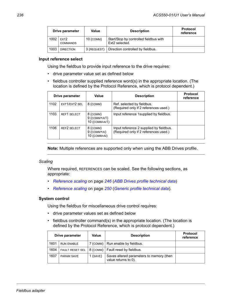
236 ACS550-01/U1 User’s Manual
Input reference selectUsing the fieldbus to provide input reference to the drive requires:
• drive parameter value set as defined below
• fieldbus controller supplied reference word(s) in the appropriate location. (The location is defined by the Protocol Reference, which is protocol dependent.)
Note: Multiple references are supported only when using the ABB Drives profile.
Scaling
Where required, REFERENCES can be scaled. See the following sections, as appropriate:
• Reference scaling on page 246 (ABB Drives profile technical data)
• Reference scaling on page 250 (Generic profile technical data).
System controlUsing the fieldbus for miscellaneous drive control requires:
• drive parameter values set as defined below
• fieldbus controller command(s) in the appropriate location. (The location is defined by the Protocol Reference, which is protocol dependent.)
1002 EXT2 COMMANDS
10 (COMM) Start/Stop by controlled fieldbus with Ext2 selected.
1003 DIRECTION 3 (REQUEST) Direction controlled by fieldbus.
Drive parameter Value Description Protocol reference
1102 EXT1/EXT2 SEL 8 (COMM) Ref. selected by fieldbus. (Required only if 2 references used.)
1103 REF1 SELECT 8 (COMM)9 (COMM+AI1)10 (COMM*AI1)
Input reference 1supplied by fieldbus.
1106 REF2 SELECT 8 (COMM)9 (COMM+AI)10 (COMM*AI)
Input reference 2 supplied by fieldbus.(Required only if 2 references used.)
Drive parameter Value Description Protocol reference
1601 RUN ENABLE 7 (COMM) Run enable by fieldbus.
1604 FAULT RESET SEL 8 (COMM) Fault reset by fieldbus.
1607 PARAM SAVE 1 (SAVE) Saves altered parameters to memory (then value returns to 0).
Drive parameter Value Description Protocol reference
Fieldbus adapter
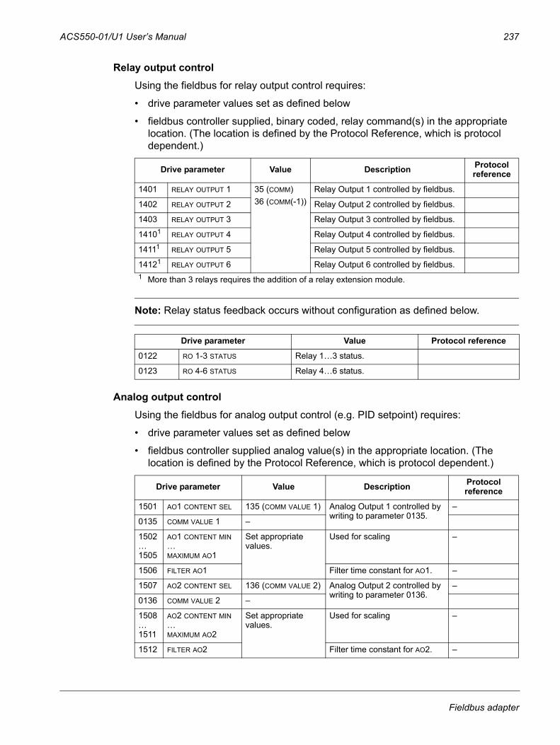
ACS550-01/U1 User’s Manual 237
Relay output controlUsing the fieldbus for relay output control requires:
• drive parameter values set as defined below
• fieldbus controller supplied, binary coded, relay command(s) in the appropriate location. (The location is defined by the Protocol Reference, which is protocol dependent.)
Note: Relay status feedback occurs without configuration as defined below.
Analog output controlUsing the fieldbus for analog output control (e.g. PID setpoint) requires:
• drive parameter values set as defined below
• fieldbus controller supplied analog value(s) in the appropriate location. (The location is defined by the Protocol Reference, which is protocol dependent.)
Drive parameter Value Description Protocol reference
1401 RELAY OUTPUT 1 35 (COMM)36 (COMM(-1))
Relay Output 1 controlled by fieldbus.
1402 RELAY OUTPUT 2 Relay Output 2 controlled by fieldbus.
1403 RELAY OUTPUT 3 Relay Output 3 controlled by fieldbus.
14101 RELAY OUTPUT 4 Relay Output 4 controlled by fieldbus.
14111 RELAY OUTPUT 5 Relay Output 5 controlled by fieldbus.
14121 RELAY OUTPUT 6 Relay Output 6 controlled by fieldbus.1 More than 3 relays requires the addition of a relay extension module.
Drive parameter Value Protocol reference
0122 RO 1-3 STATUS Relay 1…3 status.
0123 RO 4-6 STATUS Relay 4…6 status.
Drive parameter Value Description Protocol reference
1501 AO1 CONTENT SEL 135 (COMM VALUE 1) Analog Output 1 controlled by writing to parameter 0135.
–
0135 COMM VALUE 1 –
1502…1505
AO1 CONTENT MIN…MAXIMUM AO1
Set appropriate values.
Used for scaling –
1506 FILTER AO1 Filter time constant for AO1. –
1507 AO2 CONTENT SEL 136 (COMM VALUE 2) Analog Output 2 controlled by writing to parameter 0136.
–
0136 COMM VALUE 2 –
1508…1511
AO2 CONTENT MIN…MAXIMUM AO2
Set appropriate values.
Used for scaling –
1512 FILTER AO2 Filter time constant for AO2. –
Fieldbus adapter
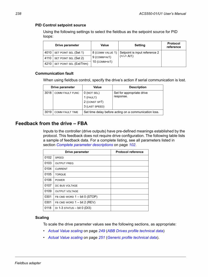
238 ACS550-01/U1 User’s Manual
PID Control setpoint source Using the following settings to select the fieldbus as the setpoint source for PID loops:
Communication faultWhen using fieldbus control, specify the drive’s action if serial communication is lost.
Feedback from the drive – FBAInputs to the controller (drive outputs) have pre-defined meanings established by the protocol. This feedback does not require drive configuration. The following table lists a sample of feedback data. For a complete listing, see all parameters listed in section Complete parameter descriptions on page 102.
ScalingTo scale the drive parameter values see the following sections, as appropriate:
• Actual Value scaling on page 249 (ABB Drives profile technical data)
• Actual Value scaling on page 251 (Generic profile technical data).
Drive parameter Value Setting Protocol reference
4010 SET POINT SEL (Set 1) 8 (COMM VALUE 1)9 (COMM+AI1)10 (COMM*AI1)
Setpoint is input reference 2 (+/-/* AI1)
4110 SET POINT SEL (Set 2)
4210 SET POINT SEL (Ext/Trim)
Drive parameter Value Description
3018 COMM FAULT FUNC 0 (NOT SEL)1 (FAULT)2 (CONST SP7)3 (LAST SPEED)
Set for appropriate drive response.
3019 COMM FAULT TIME Set time delay before acting on a communication loss.
Drive parameter Protocol reference
0102 SPEED
0103 OUTPUT FREQ
0104 CURRENT
0105 TORQUE
0106 POWER
0107 DC BUS VOLTAGE
0109 OUTPUT VOLTAGE
0301 FB CMD WORD 1 – bit 0 (STOP)
0301 FB CMD WORD 1 – bit 2 (REV)
0118 DI 1-3 STATUS – bit 0 (DI3)
Fieldbus adapter
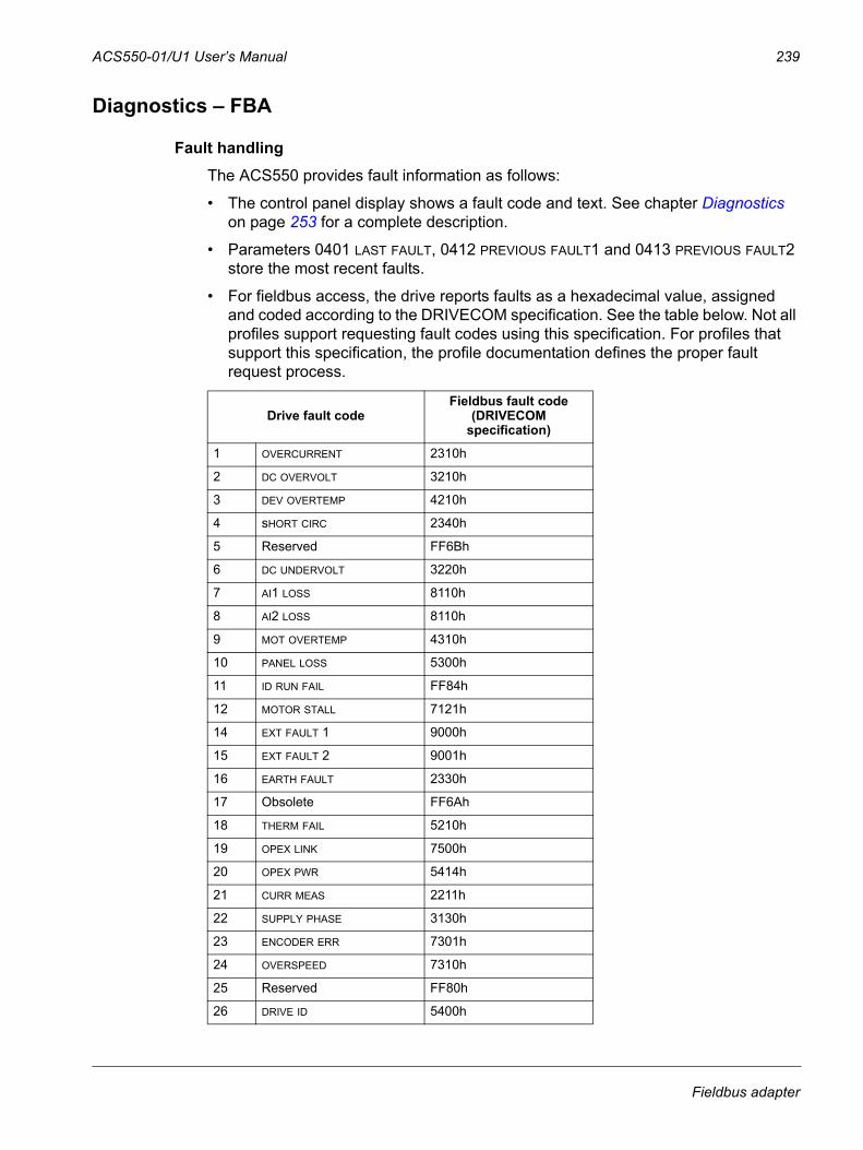
ACS550-01/U1 User’s Manual 239
Diagnostics – FBA
Fault handlingThe ACS550 provides fault information as follows:
• The control panel display shows a fault code and text. See chapter Diagnostics on page 253 for a complete description.
• Parameters 0401 LAST FAULT, 0412 PREVIOUS FAULT1 and 0413 PREVIOUS FAULT2 store the most recent faults.
• For fieldbus access, the drive reports faults as a hexadecimal value, assigned and coded according to the DRIVECOM specification. See the table below. Not all profiles support requesting fault codes using this specification. For profiles that support this specification, the profile documentation defines the proper fault request process.
Drive fault codeFieldbus fault code
(DRIVECOM specification)
1 OVERCURRENT 2310h
2 DC OVERVOLT 3210h
3 DEV OVERTEMP 4210h
4 sHORT CIRC 2340h
5 Reserved FF6Bh
6 DC UNDERVOLT 3220h
7 AI1 LOSS 8110h
8 AI2 LOSS 8110h
9 MOT OVERTEMP 4310h
10 PANEL LOSS 5300h
11 ID RUN FAIL FF84h
12 MOTOR STALL 7121h
14 EXT FAULT 1 9000h
15 EXT FAULT 2 9001h
16 EARTH FAULT 2330h
17 Obsolete FF6Ah
18 THERM FAIL 5210h
19 OPEX LINK 7500h
20 OPEX PWR 5414h
21 CURR MEAS 2211h
22 SUPPLY PHASE 3130h
23 ENCODER ERR 7301h
24 OVERSPEED 7310h
25 Reserved FF80h
26 DRIVE ID 5400h
Fieldbus adapter
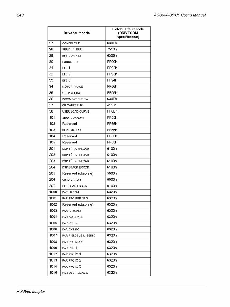
240 ACS550-01/U1 User’s Manual
27 CONFIG FILE 630Fh
28 SERIAL 1 ERR 7510h
29 EFB CON FILE 6306h
30 FORCE TRIP FF90h
31 EFB 1 FF92h
32 EFB 2 FF93h
33 EFB 3 FF94h
34 MOTOR PHASE FF56h
35 OUTP WIRING FF95h
36 INCOMPATIBLE SW 630Fh
37 CB OVERTEMP 4110h
38 USER LOAD CURVE FF6Bh
101 SERF CORRUPT FF55h
102 Reserved FF55h
103 SERF MACRO FF55h
104 Reserved FF55h
105 Reserved FF55h
201 DSP T1 OVERLOAD 6100h
202 DSP T2 OVERLOAD 6100h
203 DSP T3 OVERLOAD 6100h
204 DSP STACK ERROR 6100h
205 Reserved (obsolete) 5000h
206 CB ID ERROR 5000h
207 EFB LOAD ERROR 6100h
1000 PAR HZRPM 6320h
1001 PAR PFC REF NEG 6320h
1002 Reserved (obsolete) 6320h
1003 PAR AI SCALE 6320h
1004 PAR AO SCALE 6320h
1005 PAR PCU 2 6320h
1006 PAR EXT RO 6320h
1007 PAR FIELDBUS MISSING 6320h
1008 PAR PFC MODE 6320h
1009 PAR PCU 1 6320h
1012 PAR PFC IO 1 6320h
1013 PAR PFC IO 2 6320h
1014 PAR PFC IO 3 6320h
1016 PAR USER LOAD C 6320h
Drive fault codeFieldbus fault code
(DRIVECOM specification)
Fieldbus adapter

ACS550-01/U1 User’s Manual 241
Serial communication diagnosticsBesides the drive fault codes, the FBA module has diagnostic tools. Refer to the user’s manual supplied with the FBA module.
Fieldbus adapter

242 ACS550-01/U1 User’s Manual
ABB Drives profile technical data
OverviewThe ABB Drives profile provides a standard profile that can be used on multiple protocols, including protocols available on the FBA module. This section describes the ABB Drives profile implemented for FBA modules.
Control WordAs described earlier in section Control interface on page 232, the CONTROL WORD is the principal means for controlling the drive from a fieldbus system.
The following table and the state diagram later in this sub-section describe the CONTROL WORD content for the ABB Drives profile.
ABB Drives profile (FBA) CONTROL WORD
Bit Name Value Commanded state Comments
0 OFF1 CONTROL
1 READY TO OPERATE Enter READY TO OPERATE
0 EMERGENCY OFF Drive ramps to stop according to currently active deceleration ramp (2203 or 2205)Normal command sequence:• Enter OFF1 ACTIVE
• Proceed to READY TO SWITCH ON, unless other interlocks (OFF2, OFF3) are active.
1 OFF2 CONTROL
1 OPERATING Continue operation (OFF2 inactive)
0 EMERGENCY OFF Drive coasts to stop. Normal command sequence:• Enter OFF2 ACTIVE
• Proceed to SWITCHON INHIBITED
2 OFF3 CONTROL
1 OPERATING Continue operation (OFF3 inactive)
0 EMERGENCY STOP Drive stops within in time specified by parameter 2208. Normal command sequence:• Enter OFF3 ACTIVE
• Proceed to SWITCH ON INHIBITED
WARNING! Be sure motor and driven equipment can be stopped using this mode.
3 INHIBIT OPERATION
1 OPERATION ENABLED
Enter OPERATION ENABLED (Note the Run enable signal must be active. See 1601. If 1601 is set to COMM, this bit also actives the Run Enable signal.)
0 OPERATION INHIBITED
Inhibit operation. Enter OPERATION INHIBITED
4 RAMP_OUT_ZERO
1 NORMAL OPERATION Enter RAMP FUNCTION GENERATOR: ACCELERATION ENABLED
0 RFG OUT ZERO Force ramp function generator output to Zero. Drive ramps to stop (current and DC voltage limits in force).
Fieldbus adapter
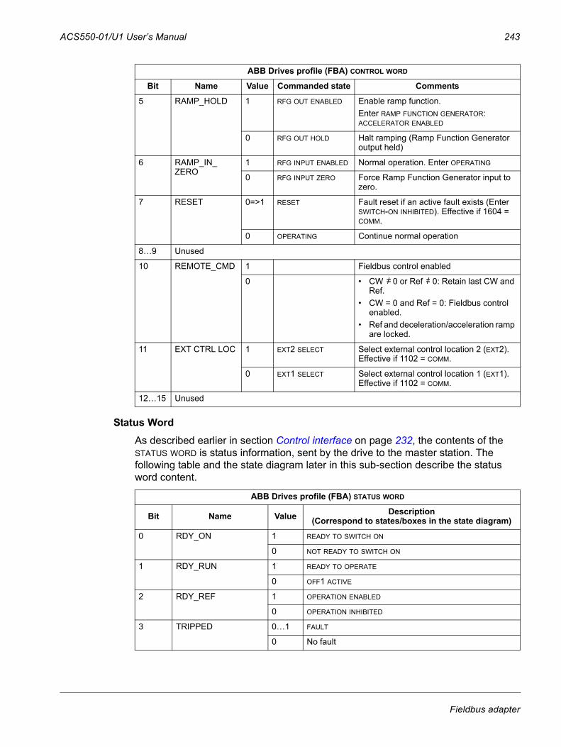
ACS550-01/U1 User’s Manual 243
Status WordAs described earlier in section Control interface on page 232, the contents of the STATUS WORD is status information, sent by the drive to the master station. The following table and the state diagram later in this sub-section describe the status word content.
5 RAMP_HOLD 1 RFG OUT ENABLED Enable ramp function.Enter RAMP FUNCTION GENERATOR: ACCELERATOR ENABLED
0 RFG OUT HOLD Halt ramping (Ramp Function Generator output held)
6 RAMP_IN_ZERO
1 RFG INPUT ENABLED Normal operation. Enter OPERATING
0 RFG INPUT ZERO Force Ramp Function Generator input to zero.
7 RESET 0=>1 RESET Fault reset if an active fault exists (Enter SWITCH-ON INHIBITED). Effective if 1604 = COMM.
0 OPERATING Continue normal operation
8…9 Unused
10 REMOTE_CMD 1 Fieldbus control enabled
0 • CW 0 or Ref 0: Retain last CW and Ref.
• CW = 0 and Ref = 0: Fieldbus control enabled.
• Ref and deceleration/acceleration ramp are locked.
11 EXT CTRL LOC 1 EXT2 SELECT Select external control location 2 (EXT2). Effective if 1102 = COMM.
0 EXT1 SELECT Select external control location 1 (EXT1). Effective if 1102 = COMM.
12…15 Unused
ABB Drives profile (FBA) STATUS WORD
Bit Name Value Description (Correspond to states/boxes in the state diagram)
0 RDY_ON 1 READY TO SWITCH ON
0 NOT READY TO SWITCH ON
1 RDY_RUN 1 READY TO OPERATE
0 OFF1 ACTIVE
2 RDY_REF 1 OPERATION ENABLED
0 OPERATION INHIBITED
3 TRIPPED 0…1 FAULT
0 No fault
ABB Drives profile (FBA) CONTROL WORD
Bit Name Value Commanded state Comments
=/ =/
Fieldbus adapter
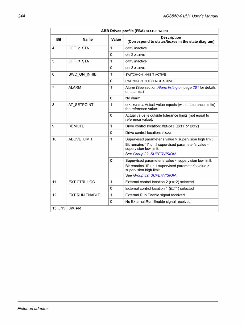
244 ACS550-01/U1 User’s Manual
4 OFF_2_STA 1 OFF2 inactive
0 OFF2 ACTIVE
5 OFF_3_STA 1 OFF3 inactive
0 OFF3 ACTIVE
6 SWC_ON_INHIB 1 SWITCH-ON INHIBIT ACTIVE
0 SWITCH-ON INHIBIT NOT ACTIVE
7 ALARM 1 Alarm (See section Alarm listing on page 261 for details on alarms.)
0 No alarm
8 AT_SETPOINT 1 OPERATING. Actual value equals (within tolerance limits) the reference value.
0 Actual value is outside tolerance limits (not equal to reference value).
9 REMOTE 1 Drive control location: REMOTE (EXT1 or EXT2)
0 Drive control location: LOCAL
10 ABOVE_LIMIT 1 Supervised parameter’s value > supervision high limit.Bit remains “1” until supervised parameter’s value < supervision low limit.See Group 32: SUPERVISION.
0 Supervised parameter’s value < supervision low limit.Bit remains “0” until supervised parameter’s value > supervision high limit.See Group 32: SUPERVISION.
11 EXT CTRL LOC 1 External control location 2 (EXT2) selected
0 External control location 1 (EXT1) selected
12 EXT RUN ENABLE 1 External Run Enable signal received
0 No External Run Enable signal received
13… 15 Unused
ABB Drives profile (FBA) STATUS WORD
Bit Name Value Description (Correspond to states/boxes in the state diagram)
Fieldbus adapter
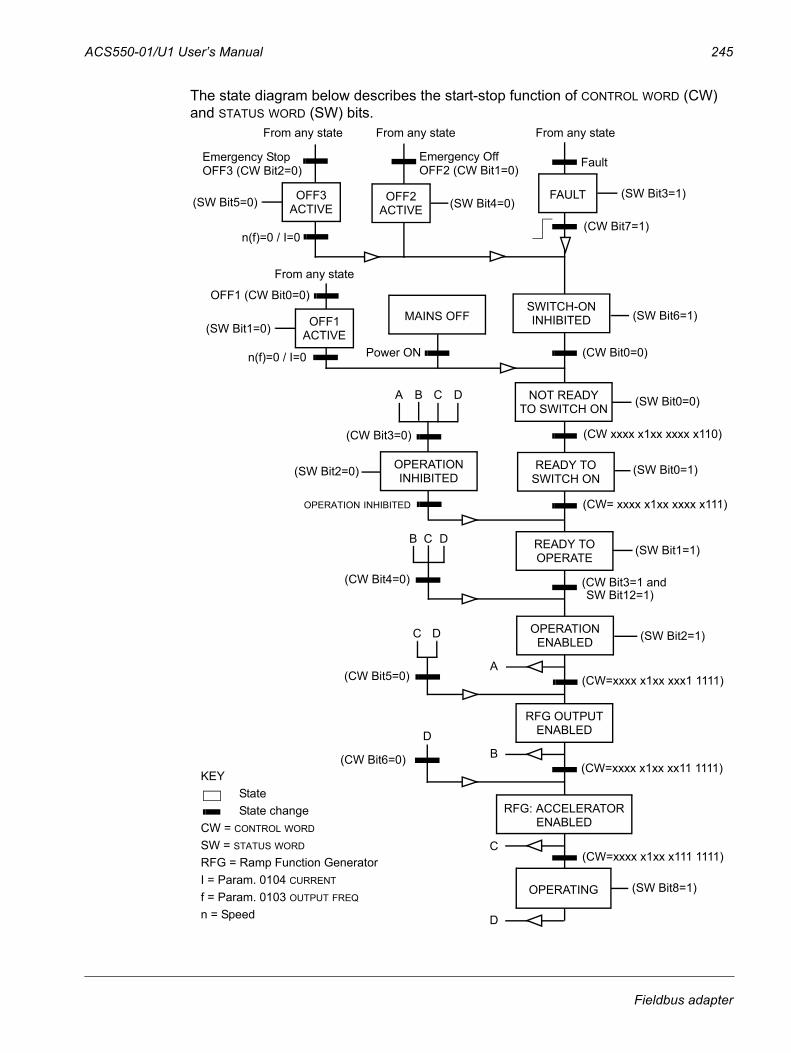
ACS550-01/U1 User’s Manual 245
The state diagram below describes the start-stop function of CONTROL WORD (CW) and STATUS WORD (SW) bits.
(CW xxxx x1xx xxxx x110)
MAINS OFF
Power ON (CW Bit0=0)
(SW Bit6=1)
(SW Bit0=0)
From any state
n(f)=0 / I=0
OFF1 (CW Bit0=0)
A C D
(CW Bit3=0)
(SW Bit2=0) (SW Bit0=1)
(CW= xxxx x1xx xxxx x111)
(SW Bit1=1)
(CW Bit3=1 and(CW Bit4=0)
n(f)=0 / I=0
From any state
SWITCH-ONINHIBITED
NOT READYTO SWITCH ON
OPERATIONINHIBITED
READY TOSWITCH ON
READY TOOPERATE
RFG OUTPUTENABLED
C D
From any state
Emergency OffOFF2 (CW Bit1=0)
(SW Bit4=0)OFF2ACTIVE
From any state
Fault
(SW Bit3=1)FAULT
(CW Bit7=1)
(SW Bit5=0)
Emergency StopOFF3 (CW Bit2=0)
SW Bit12=1)
RFG: ACCELERATORENABLED
(CW=xxxx x1xx xx11 1111)(CW Bit6=0)
C(CW=xxxx x1xx x111 1111)
(SW Bit8=1)
D
BD
OPERATING
OFF3ACTIVE
KEYStateState change
CW = CONTROL WORD
SW = STATUS WORD
RFG = Ramp Function GeneratorI = Param. 0104 CURRENT
f = Param. 0103 OUTPUT FREQ
n = Speed
(SW Bit2=1)OPERATIONENABLED
(CW=xxxx x1xx xxx1 1111)A
(CW Bit5=0)
C D
B
B
(SW Bit1=0) OFF1ACTIVE
OPERATION INHIBITED
Fieldbus adapter
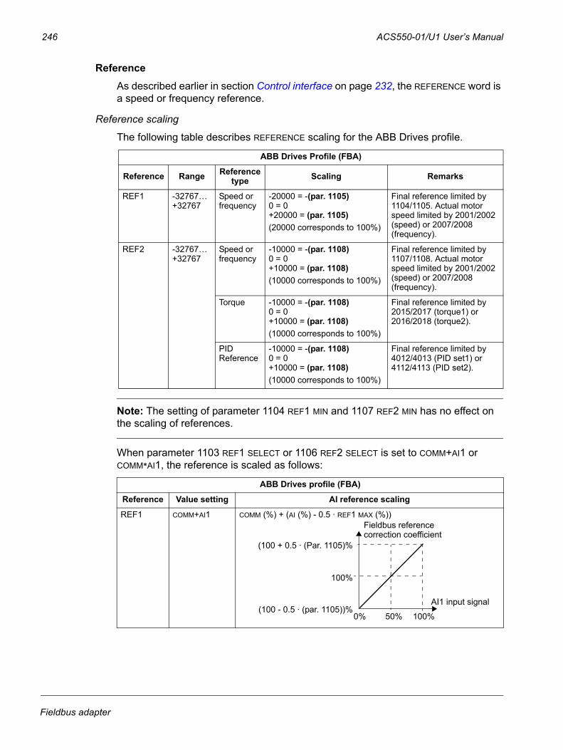
246 ACS550-01/U1 User’s Manual
Reference As described earlier in section Control interface on page 232, the REFERENCE word is a speed or frequency reference.
Reference scaling
The following table describes REFERENCE scaling for the ABB Drives profile.
Note: The setting of parameter 1104 REF1 MIN and 1107 REF2 MIN has no effect on the scaling of references.
When parameter 1103 REF1 SELECT or 1106 REF2 SELECT is set to COMM+AI1 or COMM*AI1, the reference is scaled as follows:
ABB Drives Profile (FBA)
Reference Range Reference type Scaling Remarks
REF1 -32767…+32767
Speed or frequency
-20000 = -(par. 1105)0 = 0+20000 = (par. 1105)(20000 corresponds to 100%)
Final reference limited by 1104/1105. Actual motor speed limited by 2001/2002 (speed) or 2007/2008 (frequency).
REF2 -32767…+32767
Speed or frequency
-10000 = -(par. 1108)0 = 0+10000 = (par. 1108)(10000 corresponds to 100%)
Final reference limited by 1107/1108. Actual motor speed limited by 2001/2002 (speed) or 2007/2008 (frequency).
Torque -10000 = -(par. 1108)0 = 0+10000 = (par. 1108)(10000 corresponds to 100%)
Final reference limited by 2015/2017 (torque1) or 2016/2018 (torque2).
PID Reference
-10000 = -(par. 1108)0 = 0+10000 = (par. 1108)(10000 corresponds to 100%)
Final reference limited by 4012/4013 (PID set1) or 4112/4113 (PID set2).
ABB Drives profile (FBA)
Reference Value setting AI reference scaling
REF1 COMM+AI1 COMM (%) + (AI (%) - 0.5 · REF1 MAX (%))
0% 50%
(100 + 0.5 · (Par. 1105)%
(100 - 0.5 · (par. 1105))%
100%
100%
AI1 input signal
Fieldbus referencecorrection coefficient
Fieldbus adapter
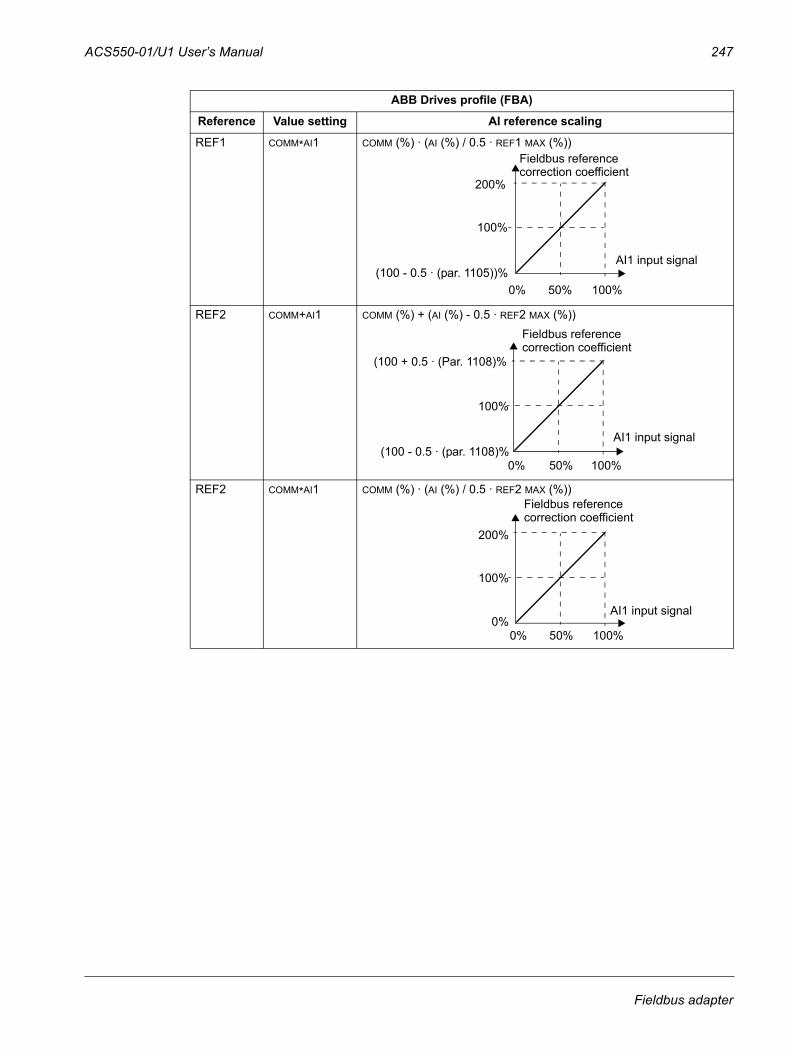
ACS550-01/U1 User’s Manual 247
REF1 COMM*AI1 COMM (%) · (AI (%) / 0.5 · REF1 MAX (%))
REF2 COMM+AI1 COMM (%) + (AI (%) - 0.5 · REF2 MAX (%))
REF2 COMM*AI1 COMM (%) · (AI (%) / 0.5 · REF2 MAX (%))
ABB Drives profile (FBA)
Reference Value setting AI reference scaling
0% 50%
200%
(100 - 0.5 · (par. 1105))%
100%
100%
AI1 input signal
Fieldbus referencecorrection coefficient
0% 50%
(100 + 0.5 · (Par. 1108)%
(100 - 0.5 · (par. 1108)%
100%
100%
AI1 input signal
Fieldbus referencecorrection coefficient
0% 50%
200%
0%
100%
100%
AI1 input signal
Fieldbus referencecorrection coefficient
Fieldbus adapter
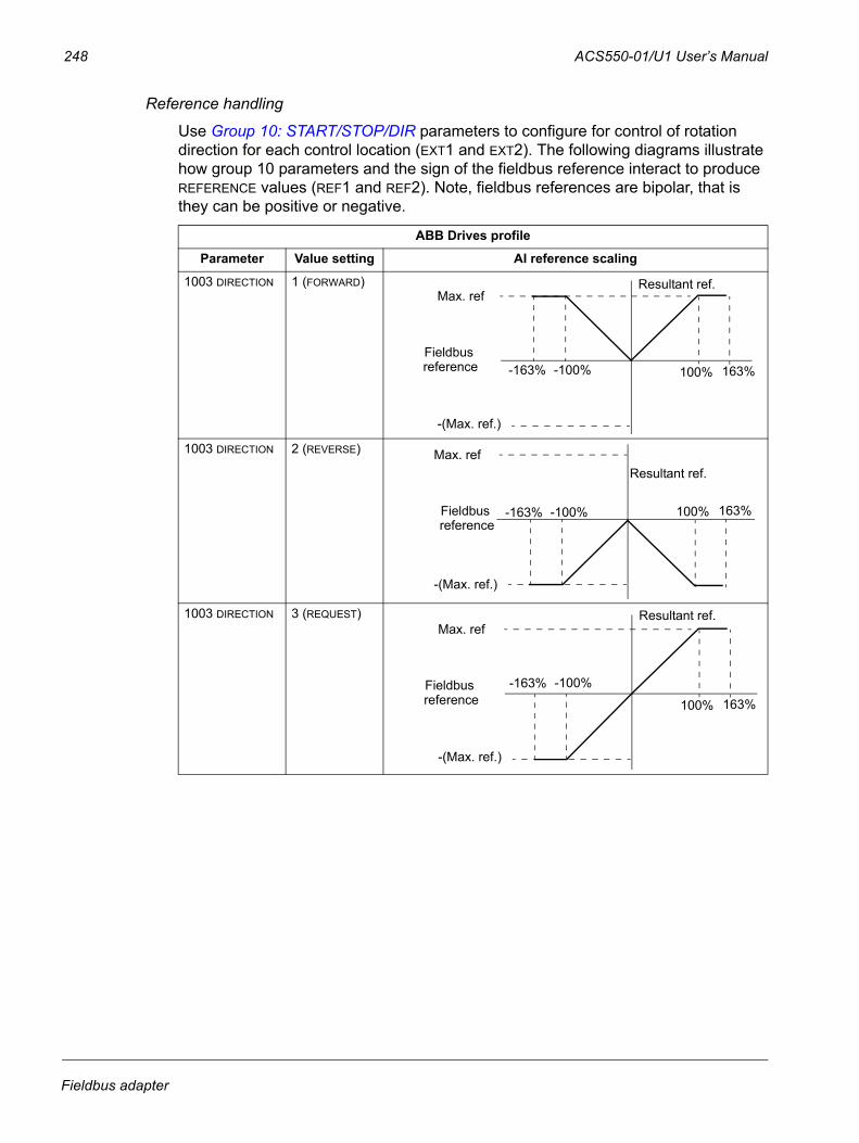
248 ACS550-01/U1 User’s Manual
Reference handling
Use Group 10: START/STOP/DIR parameters to configure for control of rotation direction for each control location (EXT1 and EXT2). The following diagrams illustrate how group 10 parameters and the sign of the fieldbus reference interact to produce REFERENCE values (REF1 and REF2). Note, fieldbus references are bipolar, that is they can be positive or negative.
ABB Drives profile
Parameter Value setting AI reference scaling
1003 DIRECTION 1 (FORWARD)
1003 DIRECTION 2 (REVERSE)
1003 DIRECTION 3 (REQUEST)
100%
Max. ref
-100%-163% 163%
-(Max. ref.)
Fieldbus
Resultant ref.
reference
100%
Max. ref
-100%-163% 163%
-(Max. ref.)
Fieldbus
Resultant ref.
reference
100%
Max. ref
-100%-163%163%
-(Max. ref.)
Fieldbus
Resultant ref.
reference
Fieldbus adapter
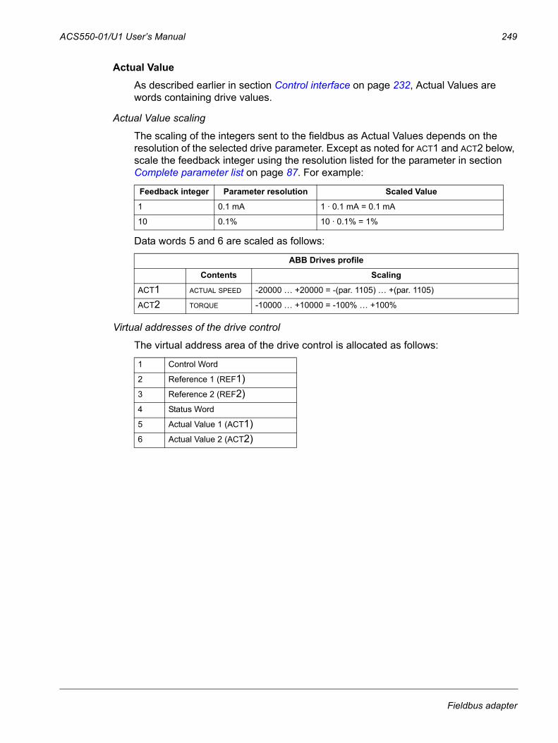
ACS550-01/U1 User’s Manual 249
Actual Value As described earlier in section Control interface on page 232, Actual Values are words containing drive values.
Actual Value scaling
The scaling of the integers sent to the fieldbus as Actual Values depends on the resolution of the selected drive parameter. Except as noted for ACT1 and ACT2 below, scale the feedback integer using the resolution listed for the parameter in section Complete parameter list on page 87. For example:
Data words 5 and 6 are scaled as follows:
Virtual addresses of the drive control
The virtual address area of the drive control is allocated as follows:
Feedback integer Parameter resolution Scaled Value
1 0.1 mA 1 · 0.1 mA = 0.1 mA
10 0.1% 10 · 0.1% = 1%
ABB Drives profile
Contents Scaling
ACT1 ACTUAL SPEED -20000 … +20000 = -(par. 1105) … +(par. 1105)
ACT2 TORQUE -10000 … +10000 = -100% … +100%
1 Control Word
2 Reference 1 (REF1)3 Reference 2 (REF2)4 Status Word
5 Actual Value 1 (ACT1)6 Actual Value 2 (ACT2)
Fieldbus adapter
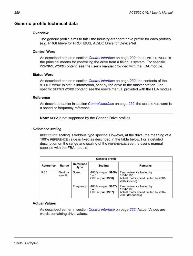
250 ACS550-01/U1 User’s Manual
Generic profile technical data
OverviewThe generic profile aims to fulfill the industry-standard drive profile for each protocol (e.g. PROFIdrive for PROFIBUS, AC/DC Drive for DeviceNet).
Control WordAs described earlier in section Control interface on page 232, the CONTROL WORD is the principal means for controlling the drive from a fieldbus system. For specific CONTROL WORD content, see the user’s manual provided with the FBA module.
Status WordAs described earlier in section Control interface on page 232, the contents of the STATUS WORD is status information, sent by the drive to the master station. For specific STATUS WORD content, see the user’s manual provided with the FBA module.
ReferenceAs described earlier in section Control interface on page 232, the REFERENCE word is a speed or frequency reference.
Note: REF2 is not supported by the Generic Drive profiles.
Reference scaling
REFERENCE scaling is fieldbus type specific. However, at the drive, the meaning of a 100% REFERENCE value is fixed as described in the table below. For a detailed description on the range and scaling of the REFERENCE, see the user’s manual supplied with the FBA module.
Actual ValuesAs described earlier in section Control interface on page 232, Actual Values are words containing drive values.
Generic profile
Reference Range Reference type Scaling Remarks
REF Fieldbus specific
Speed -100% = -(par. 9908)0 = 0+100 = (par. 9908)
Final reference limited by1104/1105. Actual motor speed limited by 2001/2002 (speed).
Frequency -100% = -(par. 9907)0 = 0+100 = (par. 9907)
Final reference limited by1104/1105. Actual motor speed limited by 2007/2008 (frequency).
Fieldbus adapter
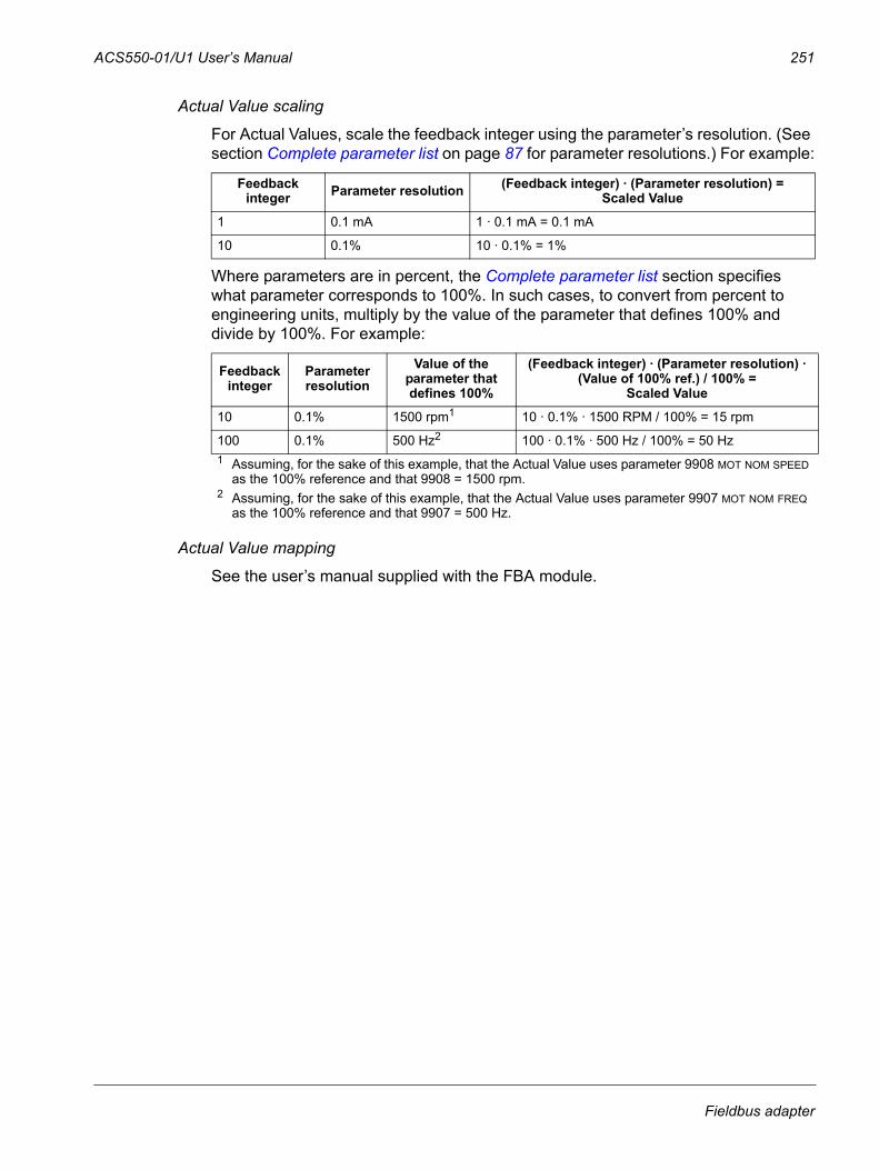
ACS550-01/U1 User’s Manual 251
Actual Value scaling
For Actual Values, scale the feedback integer using the parameter’s resolution. (See section Complete parameter list on page 87 for parameter resolutions.) For example:
Where parameters are in percent, the Complete parameter list section specifies what parameter corresponds to 100%. In such cases, to convert from percent to engineering units, multiply by the value of the parameter that defines 100% and divide by 100%. For example:
Actual Value mapping
See the user’s manual supplied with the FBA module.
Feedback integer Parameter resolution (Feedback integer) · (Parameter resolution) =
Scaled Value
1 0.1 mA 1 · 0.1 mA = 0.1 mA
10 0.1% 10 · 0.1% = 1%
Feedback integer
Parameter resolution
Value of the parameter that defines 100%
(Feedback integer) · (Parameter resolution) · (Value of 100% ref.) / 100% =
Scaled Value
10 0.1% 1500 rpm1 10 · 0.1% · 1500 RPM / 100% = 15 rpm
100 0.1% 500 Hz2 100 · 0.1% · 500 Hz / 100% = 50 Hz1 Assuming, for the sake of this example, that the Actual Value uses parameter 9908 MOT NOM SPEED
as the 100% reference and that 9908 = 1500 rpm.2 Assuming, for the sake of this example, that the Actual Value uses parameter 9907 MOT NOM FREQ
as the 100% reference and that 9907 = 500 Hz.
Fieldbus adapter

252 ACS550-01/U1 User’s Manual
Fieldbus adapter
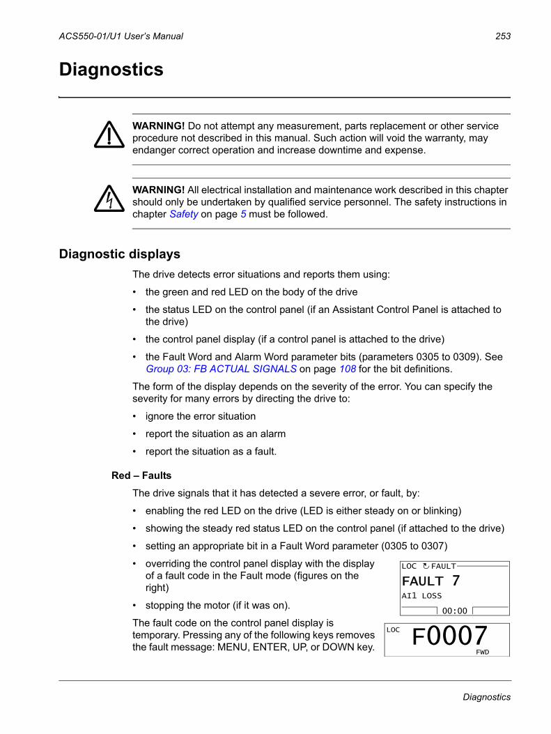
ACS550-01/U1 User’s Manual 253
Diagnostics
WARNING! Do not attempt any measurement, parts replacement or other service procedure not described in this manual. Such action will void the warranty, may endanger correct operation and increase downtime and expense.
WARNING! All electrical installation and maintenance work described in this chapter should only be undertaken by qualified service personnel. The safety instructions in chapter Safety on page 5 must be followed.
Diagnostic displaysThe drive detects error situations and reports them using:
• the green and red LED on the body of the drive
• the status LED on the control panel (if an Assistant Control Panel is attached to the drive)
• the control panel display (if a control panel is attached to the drive)
• the Fault Word and Alarm Word parameter bits (parameters 0305 to 0309). See Group 03: FB ACTUAL SIGNALS on page 108 for the bit definitions.
The form of the display depends on the severity of the error. You can specify the severity for many errors by directing the drive to:
• ignore the error situation
• report the situation as an alarm
• report the situation as a fault.
Red – FaultsThe drive signals that it has detected a severe error, or fault, by:
• enabling the red LED on the drive (LED is either steady on or blinking)
• showing the steady red status LED on the control panel (if attached to the drive)
• setting an appropriate bit in a Fault Word parameter (0305 to 0307)
• overriding the control panel display with the display of a fault code in the Fault mode (figures on the right)
• stopping the motor (if it was on).
The fault code on the control panel display is temporary. Pressing any of the following keys removes the fault message: MENU, ENTER, UP, or DOWN key.
00:00
AI1 LOSS
FAULTLOC
FAULT 7
LOC
FWD
F0007
Diagnostics
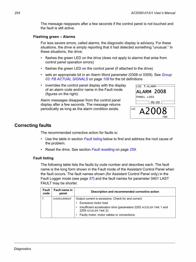
254 ACS550-01/U1 User’s Manual
The message reappears after a few seconds if the control panel is not touched and the fault is still active.
Flashing green – AlarmsFor less severe errors, called alarms, the diagnostic display is advisory. For these situations, the drive is simply reporting that it had detected something “unusual.” In these situations, the drive:
• flashes the green LED on the drive (does not apply to alarms that arise from control panel operation errors)
• flashes the green LED on the control panel (if attached to the drive)
• sets an appropriate bit in an Alarm Word parameter (0308 or 0309). See Group 03: FB ACTUAL SIGNALS on page 108 for the bit definitions
• overrides the control panel display with the display of an alarm code and/or name in the Fault mode (figures on the right).
Alarm messages disappear from the control panel display after a few seconds. The message returns periodically as long as the alarm condition exists.
Correcting faultsThe recommended corrective action for faults is:
• Use the table in section Fault listing below to find and address the root cause of the problem.
• Reset the drive. See section Fault resetting on page 259.
Fault listing
The following table lists the faults by code number and describes each. The fault name is the long form shown in the Fault mode of the Assistant Control Panel when the fault occurs. The fault names shown (for Assistant Control Panel only) in the Fault Logger mode (see page 57) and the fault names for parameter 0401 LAST FAULT may be shorter.
Fault code
Fault name in panel Description and recommended corrective action
1 OVERCURRENT Output current is excessive. Check for and correct:• Excessive motor load.• Insufficient acceleration time (parameters 2202 ACCELER TIME 1 and
2205 ACCELER TIME 2).• Faulty motor, motor cables or connections.
00:00
PANEL LOSS
ALARMLOC
ALARM 2008
LOC
FWD
A2008
Diagnostics
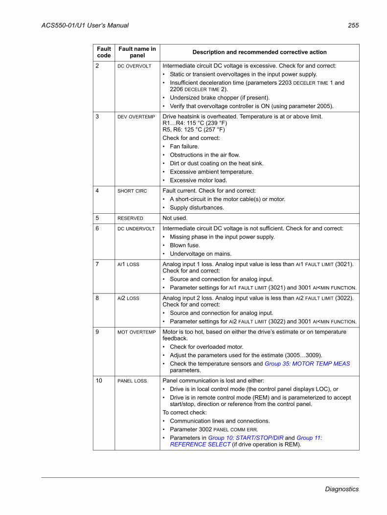
ACS550-01/U1 User’s Manual 255
2 DC OVERVOLT Intermediate circuit DC voltage is excessive. Check for and correct:• Static or transient overvoltages in the input power supply. • Insufficient deceleration time (parameters 2203 DECELER TIME 1 and
2206 DECELER TIME 2).• Undersized brake chopper (if present).• Verify that overvoltage controller is ON (using parameter 2005).
3 DEV OVERTEMP Drive heatsink is overheated. Temperature is at or above limit.R1…R4: 115 °C (239 °F)R5, R6: 125 °C (257 °F) Check for and correct:• Fan failure.• Obstructions in the air flow.• Dirt or dust coating on the heat sink.• Excessive ambient temperature.• Excessive motor load.
4 SHORT CIRC Fault current. Check for and correct:• A short-circuit in the motor cable(s) or motor.• Supply disturbances.
5 RESERVED Not used.
6 DC UNDERVOLT Intermediate circuit DC voltage is not sufficient. Check for and correct:• Missing phase in the input power supply.• Blown fuse.• Undervoltage on mains.
7 AI1 LOSS Analog input 1 loss. Analog input value is less than AI1 FAULT LIMIT (3021). Check for and correct:• Source and connection for analog input.• Parameter settings for AI1 FAULT LIMIT (3021) and 3001 AI<MIN FUNCTION.
8 AI2 LOSS Analog input 2 loss. Analog input value is less than AI2 FAULT LIMIT (3022). Check for and correct:• Source and connection for analog input.• Parameter settings for AI2 FAULT LIMIT (3022) and 3001 AI<MIN FUNCTION.
9 MOT OVERTEMP Motor is too hot, based on either the drive’s estimate or on temperature feedback.• Check for overloaded motor.• Adjust the parameters used for the estimate (3005…3009).• Check the temperature sensors and Group 35: MOTOR TEMP MEAS
parameters.
10 PANEL LOSS Panel communication is lost and either:• Drive is in local control mode (the control panel displays LOC), or• Drive is in remote control mode (REM) and is parameterized to accept
start/stop, direction or reference from the control panel. To correct check:• Communication lines and connections.• Parameter 3002 PANEL COMM ERR.• Parameters in Group 10: START/STOP/DIR and Group 11:
REFERENCE SELECT (if drive operation is REM).
Fault code
Fault name in panel Description and recommended corrective action
Diagnostics
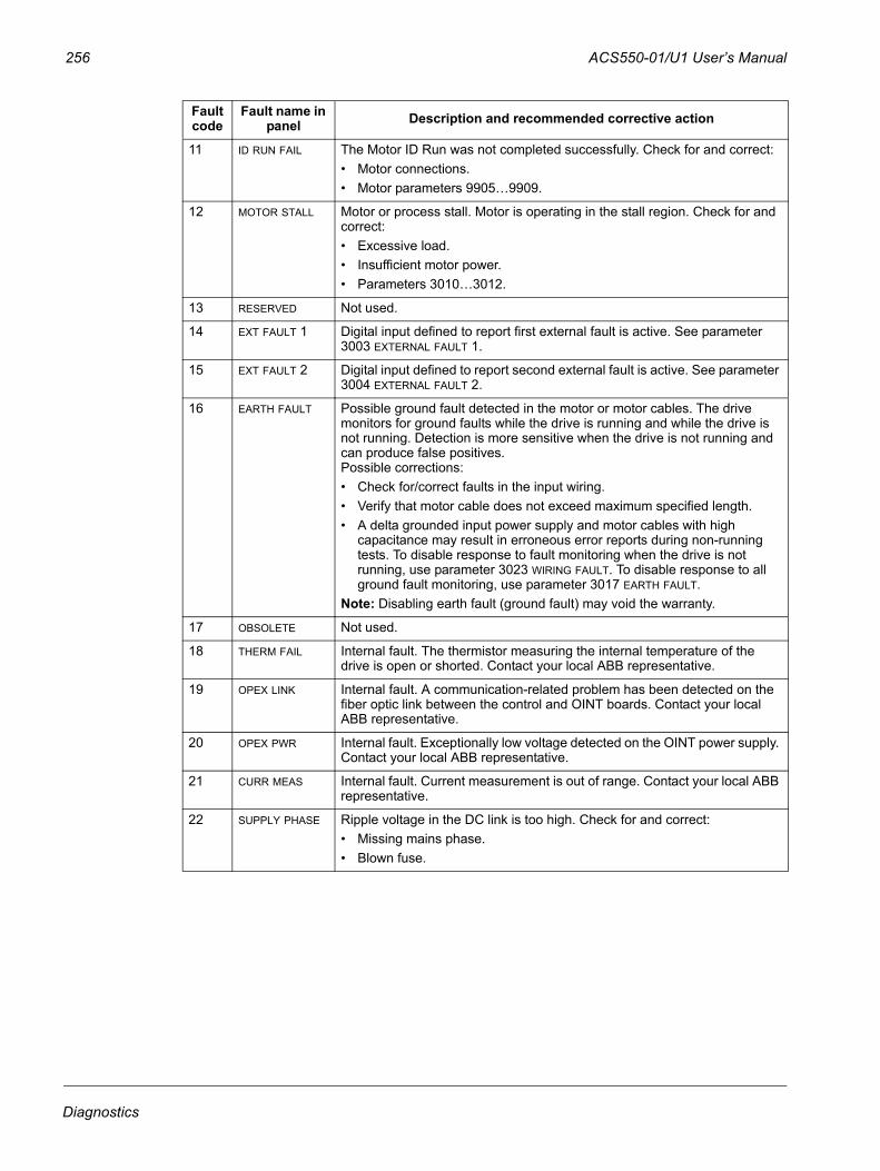
256 ACS550-01/U1 User’s Manual
11 ID RUN FAIL The Motor ID Run was not completed successfully. Check for and correct:• Motor connections.• Motor parameters 9905…9909.
12 MOTOR STALL Motor or process stall. Motor is operating in the stall region. Check for and correct:• Excessive load.• Insufficient motor power. • Parameters 3010…3012.
13 RESERVED Not used.
14 EXT FAULT 1 Digital input defined to report first external fault is active. See parameter 3003 EXTERNAL FAULT 1.
15 EXT FAULT 2 Digital input defined to report second external fault is active. See parameter 3004 EXTERNAL FAULT 2.
16 EARTH FAULT Possible ground fault detected in the motor or motor cables. The drive monitors for ground faults while the drive is running and while the drive is not running. Detection is more sensitive when the drive is not running and can produce false positives.Possible corrections:• Check for/correct faults in the input wiring.• Verify that motor cable does not exceed maximum specified length.• A delta grounded input power supply and motor cables with high
capacitance may result in erroneous error reports during non-running tests. To disable response to fault monitoring when the drive is not running, use parameter 3023 WIRING FAULT. To disable response to all ground fault monitoring, use parameter 3017 EARTH FAULT.
Note: Disabling earth fault (ground fault) may void the warranty.
17 OBSOLETE Not used.
18 THERM FAIL Internal fault. The thermistor measuring the internal temperature of the drive is open or shorted. Contact your local ABB representative.
19 OPEX LINK Internal fault. A communication-related problem has been detected on the fiber optic link between the control and OINT boards. Contact your local ABB representative.
20 OPEX PWR Internal fault. Exceptionally low voltage detected on the OINT power supply. Contact your local ABB representative.
21 CURR MEAS Internal fault. Current measurement is out of range. Contact your local ABB representative.
22 SUPPLY PHASE Ripple voltage in the DC link is too high. Check for and correct:• Missing mains phase.• Blown fuse.
Fault code
Fault name in panel Description and recommended corrective action
Diagnostics
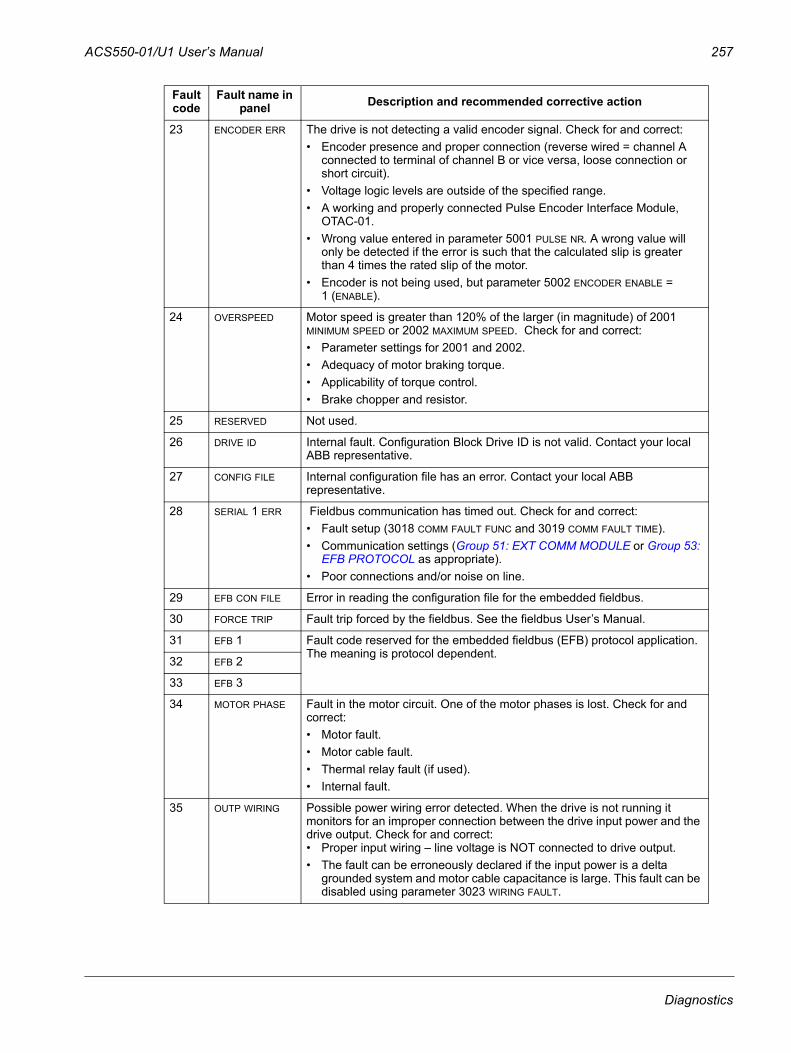
ACS550-01/U1 User’s Manual 257
23 ENCODER ERR The drive is not detecting a valid encoder signal. Check for and correct:• Encoder presence and proper connection (reverse wired = channel A
connected to terminal of channel B or vice versa, loose connection or short circuit).
• Voltage logic levels are outside of the specified range.• A working and properly connected Pulse Encoder Interface Module,
OTAC-01.• Wrong value entered in parameter 5001 PULSE NR. A wrong value will
only be detected if the error is such that the calculated slip is greater than 4 times the rated slip of the motor.
• Encoder is not being used, but parameter 5002 ENCODER ENABLE = 1 (ENABLE).
24 OVERSPEED Motor speed is greater than 120% of the larger (in magnitude) of 2001 MINIMUM SPEED or 2002 MAXIMUM SPEED. Check for and correct:• Parameter settings for 2001 and 2002.• Adequacy of motor braking torque.• Applicability of torque control.• Brake chopper and resistor.
25 RESERVED Not used.
26 DRIVE ID Internal fault. Configuration Block Drive ID is not valid. Contact your local ABB representative.
27 CONFIG FILE Internal configuration file has an error. Contact your local ABB representative.
28 SERIAL 1 ERR Fieldbus communication has timed out. Check for and correct:• Fault setup (3018 COMM FAULT FUNC and 3019 COMM FAULT TIME).• Communication settings (Group 51: EXT COMM MODULE or Group 53:
EFB PROTOCOL as appropriate).• Poor connections and/or noise on line.
29 EFB CON FILE Error in reading the configuration file for the embedded fieldbus.
30 FORCE TRIP Fault trip forced by the fieldbus. See the fieldbus User’s Manual.
31 EFB 1 Fault code reserved for the embedded fieldbus (EFB) protocol application. The meaning is protocol dependent.
32 EFB 2
33 EFB 3
34 MOTOR PHASE Fault in the motor circuit. One of the motor phases is lost. Check for and correct:• Motor fault.• Motor cable fault.• Thermal relay fault (if used).• Internal fault.
35 OUTP WIRING Possible power wiring error detected. When the drive is not running it monitors for an improper connection between the drive input power and the drive output. Check for and correct:• Proper input wiring – line voltage is NOT connected to drive output.• The fault can be erroneously declared if the input power is a delta
grounded system and motor cable capacitance is large. This fault can be disabled using parameter 3023 WIRING FAULT.
Fault code
Fault name in panel Description and recommended corrective action
Diagnostics
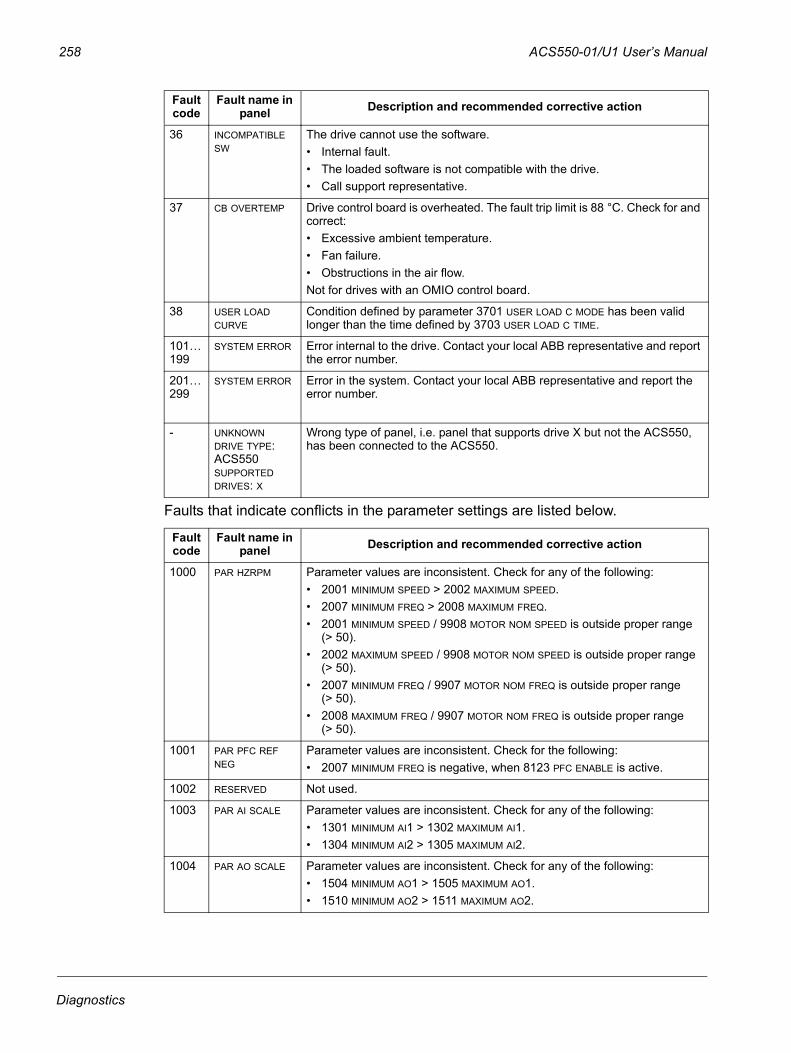
258 ACS550-01/U1 User’s Manual
Faults that indicate conflicts in the parameter settings are listed below.
36 INCOMPATIBLE SW
The drive cannot use the software.• Internal fault.• The loaded software is not compatible with the drive. • Call support representative.
37 CB OVERTEMP Drive control board is overheated. The fault trip limit is 88 °C. Check for and correct:• Excessive ambient temperature.• Fan failure.• Obstructions in the air flow.Not for drives with an OMIO control board.
38 USER LOAD CURVE
Condition defined by parameter 3701 USER LOAD C MODE has been valid longer than the time defined by 3703 USER LOAD C TIME.
101…199
SYSTEM ERROR Error internal to the drive. Contact your local ABB representative and report the error number.
201…299
SYSTEM ERROR Error in the system. Contact your local ABB representative and report the error number.
- UNKNOWN DRIVE TYPE: ACS550SUPPORTED DRIVES: X
Wrong type of panel, i.e. panel that supports drive X but not the ACS550, has been connected to the ACS550.
Fault code
Fault name in panel Description and recommended corrective action
1000 PAR HZRPM Parameter values are inconsistent. Check for any of the following:• 2001 MINIMUM SPEED > 2002 MAXIMUM SPEED.• 2007 MINIMUM FREQ > 2008 MAXIMUM FREQ.• 2001 MINIMUM SPEED / 9908 MOTOR NOM SPEED is outside proper range
(> 50).• 2002 MAXIMUM SPEED / 9908 MOTOR NOM SPEED is outside proper range
(> 50).• 2007 MINIMUM FREQ / 9907 MOTOR NOM FREQ is outside proper range
(> 50).• 2008 MAXIMUM FREQ / 9907 MOTOR NOM FREQ is outside proper range
(> 50).
1001 PAR PFC REF NEG
Parameter values are inconsistent. Check for the following:• 2007 MINIMUM FREQ is negative, when 8123 PFC ENABLE is active.
1002 RESERVED Not used.
1003 PAR AI SCALE Parameter values are inconsistent. Check for any of the following:• 1301 MINIMUM AI1 > 1302 MAXIMUM AI1.• 1304 MINIMUM AI2 > 1305 MAXIMUM AI2.
1004 PAR AO SCALE Parameter values are inconsistent. Check for any of the following:• 1504 MINIMUM AO1 > 1505 MAXIMUM AO1.• 1510 MINIMUM AO2 > 1511 MAXIMUM AO2.
Fault code
Fault name in panel Description and recommended corrective action
Diagnostics
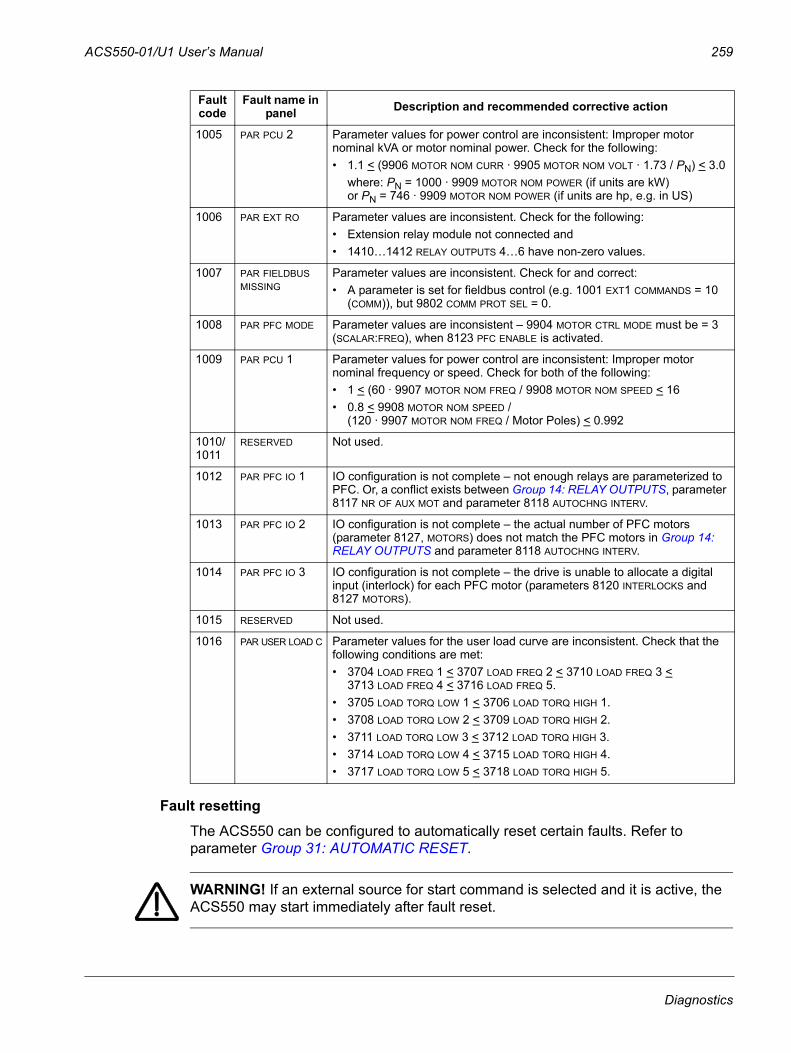
ACS550-01/U1 User’s Manual 259
Fault resettingThe ACS550 can be configured to automatically reset certain faults. Refer to parameter Group 31: AUTOMATIC RESET.
WARNING! If an external source for start command is selected and it is active, the ACS550 may start immediately after fault reset.
1005 PAR PCU 2 Parameter values for power control are inconsistent: Improper motor nominal kVA or motor nominal power. Check for the following:• 1.1 < (9906 MOTOR NOM CURR · 9905 MOTOR NOM VOLT · 1.73 / PN) < 3.0
where: PN = 1000 · 9909 MOTOR NOM POWER (if units are kW)or PN = 746 · 9909 MOTOR NOM POWER (if units are hp, e.g. in US)
1006 PAR EXT RO Parameter values are inconsistent. Check for the following:• Extension relay module not connected and • 1410…1412 RELAY OUTPUTS 4…6 have non-zero values.
1007 PAR FIELDBUS MISSING
Parameter values are inconsistent. Check for and correct:• A parameter is set for fieldbus control (e.g. 1001 EXT1 COMMANDS = 10
(COMM)), but 9802 COMM PROT SEL = 0.
1008 PAR PFC MODE Parameter values are inconsistent – 9904 MOTOR CTRL MODE must be = 3 (SCALAR:FREQ), when 8123 PFC ENABLE is activated.
1009 PAR PCU 1 Parameter values for power control are inconsistent: Improper motor nominal frequency or speed. Check for both of the following:• 1 < (60 · 9907 MOTOR NOM FREQ / 9908 MOTOR NOM SPEED < 16• 0.8 < 9908 MOTOR NOM SPEED /
(120 · 9907 MOTOR NOM FREQ / Motor Poles) < 0.992
1010/1011
RESERVED Not used.
1012 PAR PFC IO 1 IO configuration is not complete – not enough relays are parameterized to PFC. Or, a conflict exists between Group 14: RELAY OUTPUTS, parameter 8117 NR OF AUX MOT and parameter 8118 AUTOCHNG INTERV.
1013 PAR PFC IO 2 IO configuration is not complete – the actual number of PFC motors (parameter 8127, MOTORS) does not match the PFC motors in Group 14: RELAY OUTPUTS and parameter 8118 AUTOCHNG INTERV.
1014 PAR PFC IO 3 IO configuration is not complete – the drive is unable to allocate a digital input (interlock) for each PFC motor (parameters 8120 INTERLOCKS and 8127 MOTORS).
1015 RESERVED Not used.
1016 PAR USER LOAD C Parameter values for the user load curve are inconsistent. Check that the following conditions are met:• 3704 LOAD FREQ 1 < 3707 LOAD FREQ 2 < 3710 LOAD FREQ 3 <
3713 LOAD FREQ 4 < 3716 LOAD FREQ 5.• 3705 LOAD TORQ LOW 1 < 3706 LOAD TORQ HIGH 1.• 3708 LOAD TORQ LOW 2 < 3709 LOAD TORQ HIGH 2.• 3711 LOAD TORQ LOW 3 < 3712 LOAD TORQ HIGH 3.• 3714 LOAD TORQ LOW 4 < 3715 LOAD TORQ HIGH 4.• 3717 LOAD TORQ LOW 5 < 3718 LOAD TORQ HIGH 5.
Fault code
Fault name in panel Description and recommended corrective action
Diagnostics

260 ACS550-01/U1 User’s Manual
Flashing red LED
To reset the drive for faults indicated by a flashing red LED:
• Turn the power off for 5 minutes.
Red LED
To reset the drive for faults indicated by a red LED (on, not flashing), correct the problem and do one of the following:
• Press RESET from the control panel.
• Turn the power off for 5 minutes.
Depending on the value of 1604 FAULT RESET SEL, the following could also be used to reset the drive:
• digital input
• serial communication.
When the fault has been corrected, the motor can be started.
HistoryFor reference, the last three fault codes are stored into parameters 0401, 0412, 0413. For the most recent fault (identified by parameter 0401), the drive stores additional data (in parameters 0402…0411) to aid in troubleshooting a problem. For example, parameter 0404 stores the motor speed at the time of the fault.
The Assistant Control Panel provides additional information about the fault history. See section Fault Logger mode on page 57 for more information.
To clear the fault history (all of the Group 04: FAULT HISTORY parameters):
1. Using the control panel in the Parameters mode, select parameter 0401.
2. Press EDIT (or ENTER on the Basic Control Panel).
3. Press UP and DOWN at the same time.
4. Press SAVE.
Correcting alarmsThe recommended corrective action for alarms is:
• Determine if the alarm requires any corrective action (action is not always required).
• Use the table in section Alarm listing below to find and address the root cause of the problem.
Diagnostics
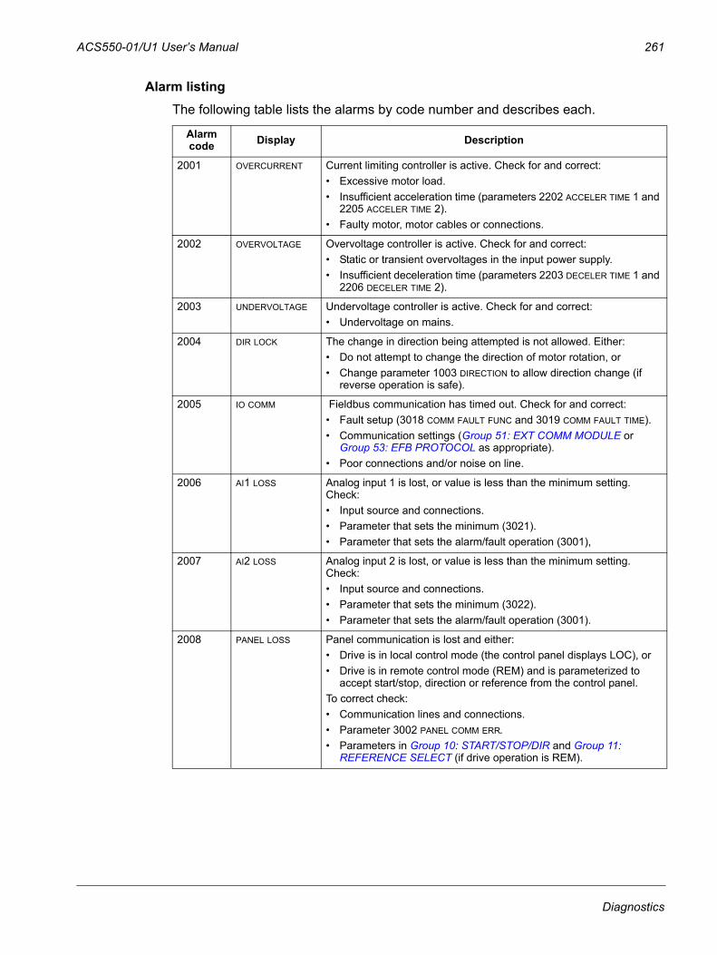
ACS550-01/U1 User’s Manual 261
Alarm listingThe following table lists the alarms by code number and describes each.
Alarm code Display Description
2001 OVERCURRENT Current limiting controller is active. Check for and correct:• Excessive motor load.• Insufficient acceleration time (parameters 2202 ACCELER TIME 1 and
2205 ACCELER TIME 2).• Faulty motor, motor cables or connections.
2002 OVERVOLTAGE Overvoltage controller is active. Check for and correct: • Static or transient overvoltages in the input power supply. • Insufficient deceleration time (parameters 2203 DECELER TIME 1 and
2206 DECELER TIME 2).
2003 UNDERVOLTAGE Undervoltage controller is active. Check for and correct: • Undervoltage on mains.
2004 DIR LOCK The change in direction being attempted is not allowed. Either:• Do not attempt to change the direction of motor rotation, or• Change parameter 1003 DIRECTION to allow direction change (if
reverse operation is safe).
2005 IO COMM Fieldbus communication has timed out. Check for and correct:• Fault setup (3018 COMM FAULT FUNC and 3019 COMM FAULT TIME).• Communication settings (Group 51: EXT COMM MODULE or
Group 53: EFB PROTOCOL as appropriate).• Poor connections and/or noise on line.
2006 AI1 LOSS Analog input 1 is lost, or value is less than the minimum setting. Check:• Input source and connections.• Parameter that sets the minimum (3021).• Parameter that sets the alarm/fault operation (3001),
2007 AI2 LOSS Analog input 2 is lost, or value is less than the minimum setting. Check:• Input source and connections.• Parameter that sets the minimum (3022).• Parameter that sets the alarm/fault operation (3001).
2008 PANEL LOSS Panel communication is lost and either:• Drive is in local control mode (the control panel displays LOC), or• Drive is in remote control mode (REM) and is parameterized to
accept start/stop, direction or reference from the control panel. To correct check:• Communication lines and connections.• Parameter 3002 PANEL COMM ERR.• Parameters in Group 10: START/STOP/DIR and Group 11:
REFERENCE SELECT (if drive operation is REM).
Diagnostics
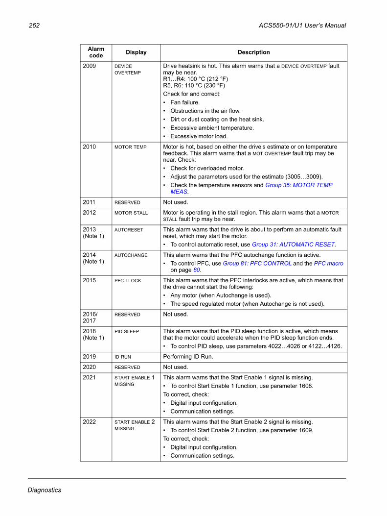
262 ACS550-01/U1 User’s Manual
2009 DEVICE OVERTEMP
Drive heatsink is hot. This alarm warns that a DEVICE OVERTEMP fault may be near.R1…R4: 100 °C (212 °F)R5, R6: 110 °C (230 °F) Check for and correct:• Fan failure.• Obstructions in the air flow.• Dirt or dust coating on the heat sink.• Excessive ambient temperature.• Excessive motor load.
2010 MOTOR TEMP Motor is hot, based on either the drive’s estimate or on temperature feedback. This alarm warns that a MOT OVERTEMP fault trip may be near. Check:• Check for overloaded motor.• Adjust the parameters used for the estimate (3005…3009).• Check the temperature sensors and Group 35: MOTOR TEMP
MEAS.
2011 RESERVED Not used.
2012 MOTOR STALL Motor is operating in the stall region. This alarm warns that a MOTOR STALL fault trip may be near.
2013 (Note 1)
AUTORESET This alarm warns that the drive is about to perform an automatic fault reset, which may start the motor. • To control automatic reset, use Group 31: AUTOMATIC RESET.
2014 (Note 1)
AUTOCHANGE This alarm warns that the PFC autochange function is active. • To control PFC, use Group 81: PFC CONTROL and the PFC macro
on page 80.
2015 PFC I LOCK This alarm warns that the PFC interlocks are active, which means that the drive cannot start the following:• Any motor (when Autochange is used). • The speed regulated motor (when Autochange is not used).
2016/2017
RESERVED Not used.
2018 (Note 1)
PID SLEEP This alarm warns that the PID sleep function is active, which means that the motor could accelerate when the PID sleep function ends. • To control PID sleep, use parameters 4022…4026 or 4122…4126.
2019 ID RUN Performing ID Run.
2020 RESERVED Not used.
2021 START ENABLE 1 MISSING
This alarm warns that the Start Enable 1 signal is missing.• To control Start Enable 1 function, use parameter 1608.To correct, check:• Digital input configuration.• Communication settings.
2022 START ENABLE 2 MISSING
This alarm warns that the Start Enable 2 signal is missing.• To control Start Enable 2 function, use parameter 1609.To correct, check:• Digital input configuration.• Communication settings.
Alarm code Display Description
Diagnostics
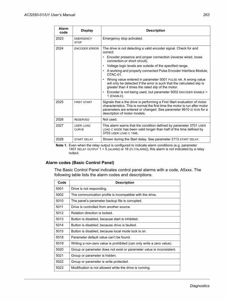
ACS550-01/U1 User’s Manual 263
Alarm codes (Basic Control Panel)The Basic Control Panel indicates control panel alarms with a code, A5xxx. The following table lists the alarm codes and descriptions.
2023 EMERGENCY STOP
Emergency stop activated.
2024 ENCODER ERROR The drive is not detecting a valid encoder signal. Check for and correct:• Encoder presence and proper connection (reverse wired, loose
connection,or short circuit).• Voltage logic levels are outside of the specified range.• A working and properly connected Pulse Encoder Interface Module,
OTAC-01.• Wrong value entered in parameter 5001 PULSE NR. A wrong value
will only be detected if the error is such that the calculated slip is greater than 4 times the rated slip of the motor.
• Encoder is not being used, but parameter 5002 ENCODER ENABLE = 1 (ENABLE).
2025 FIRST START Signals that a the drive is performing a First Start evaluation of motor characteristics. This is normal the first time the motor is run after motor parameters are entered or changed. See parameter 9910 ID RUN for a description of motor models.
2026 RESERVED Not used.
2027 USER LOAD CURVE
This alarm warns that the condition defined by parameter 3701 USER LOAD C MODE has been valid longer than half of the time defined by 3703 USER LOAD C TIME.
2028 START DELAY Shown during the Start delay. See parameter 2113 START DELAY.
Note 1. Even when the relay output is configured to indicate alarm conditions (e.g. parameter 1401 RELAY OUTPUT 1 = 5 (ALARM) or 16 (FLT/ALARM)), this alarm is not indicated by a relay output.
Code Description
5001 Drive is not responding.
5002 The communication profile is incompatible with the drive.
5010 The panel’s parameter backup file is corrupted.
5011 Drive is controlled from another source.
5012 Rotation direction is locked.
5013 Button is disabled, because start is inhibited.
5014 Button is disabled, because drive is faulted.
5015 Button is disabled, because local mode lock is on.
5018 Parameter default value can’t be found.
5019 Writing a non-zero value is prohibited (can only write a zero value).
5020 Group or parameter does not exist or parameter value is inconsistent.
5021 Group or parameter is hidden.
5022 Group or parameter is write protected.
5023 Modification is not allowed while the drive is running.
Alarm code Display Description
Diagnostics
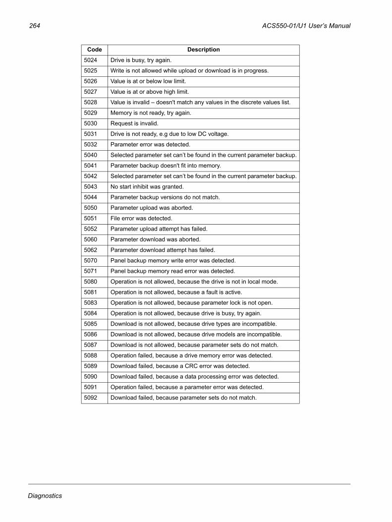
264 ACS550-01/U1 User’s Manual
5024 Drive is busy, try again.
5025 Write is not allowed while upload or download is in progress.
5026 Value is at or below low limit.
5027 Value is at or above high limit.
5028 Value is invalid – doesn't match any values in the discrete values list.
5029 Memory is not ready, try again.
5030 Request is invalid.
5031 Drive is not ready, e.g due to low DC voltage.
5032 Parameter error was detected.
5040 Selected parameter set can’t be found in the current parameter backup.
5041 Parameter backup doesn't fit into memory.
5042 Selected parameter set can’t be found in the current parameter backup.
5043 No start inhibit was granted.
5044 Parameter backup versions do not match.
5050 Parameter upload was aborted.
5051 File error was detected.
5052 Parameter upload attempt has failed.
5060 Parameter download was aborted.
5062 Parameter download attempt has failed.
5070 Panel backup memory write error was detected.
5071 Panel backup memory read error was detected.
5080 Operation is not allowed, because the drive is not in local mode.
5081 Operation is not allowed, because a fault is active.
5083 Operation is not allowed, because parameter lock is not open.
5084 Operation is not allowed, because drive is busy, try again.
5085 Download is not allowed, because drive types are incompatible.
5086 Download is not allowed, because drive models are incompatible.
5087 Download is not allowed, because parameter sets do not match.
5088 Operation failed, because a drive memory error was detected.
5089 Download failed, because a CRC error was detected.
5090 Download failed, because a data processing error was detected.
5091 Operation failed, because a parameter error was detected.
5092 Download failed, because parameter sets do not match.
Code Description
Diagnostics
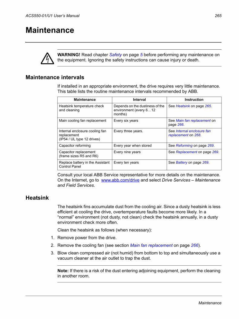
ACS550-01/U1 User’s Manual 265
Maintenance
WARNING! Read chapter Safety on page 5 before performing any maintenance on the equipment. Ignoring the safety instructions can cause injury or death.
Maintenance intervalsIf installed in an appropriate environment, the drive requires very little maintenance. This table lists the routine maintenance intervals recommended by ABB.
Consult your local ABB Service representative for more details on the maintenance. On the Internet, go to www.abb.com/drive and select Drive Services – Maintenance and Field Services.
HeatsinkThe heatsink fins accumulate dust from the cooling air. Since a dusty heatsink is less efficient at cooling the drive, overtemperature faults become more likely. In a “normal” environment (not dusty, not clean) check the heatsink annually, in a dusty environment check more often.
Clean the heatsink as follows (when necessary):
1. Remove power from the drive.
2. Remove the cooling fan (see section Main fan replacement on page 266).
3. Blow clean compressed air (not humid) from bottom to top and simultaneously use a vacuum cleaner at the air outlet to trap the dust.
Note: If there is a risk of the dust entering adjoining equipment, perform the cleaning in another room.
Maintenance Interval Instruction
Heatsink temperature check and cleaning
Depends on the dustiness of the environment (every 6…12 months)
See Heatsink on page 265.
Main cooling fan replacement Every six years See Main fan replacement on page 266.
Internal enclosure cooling fan replacement (IP54 / UL type 12 drives)
Every three years. See Internal enclosure fan replacement on 268.
Capacitor reforming Every year when stored See Reforming on page 269.
Capacitor replacement (frame sizes R5 and R6)
Every nine years See Replacement on page 269.
Replace battery in the Assistant Control Panel
Every ten years See Battery on page 269.
Maintenance
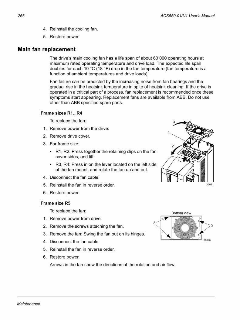
266 ACS550-01/U1 User’s Manual
4. Reinstall the cooling fan.
5. Restore power.
Main fan replacementThe drive’s main cooling fan has a life span of about 60 000 operating hours at maximum rated operating temperature and drive load. The expected life span doubles for each 10 °C (18 °F) drop in the fan temperature (fan temperature is a function of ambient temperatures and drive loads).
Fan failure can be predicted by the increasing noise from fan bearings and the gradual rise in the heatsink temperature in spite of heatsink cleaning. If the drive is operated in a critical part of a process, fan replacement is recommended once these symptoms start appearing. Replacement fans are available from ABB. Do not use other than ABB specified spare parts.
Frame sizes R1…R4To replace the fan:
1. Remove power from the drive.
2. Remove drive cover.
3. For frame size:
• R1, R2: Press together the retaining clips on the fan cover sides, and lift.
• R3, R4: Press in on the lever located on the left side of the fan mount, and rotate the fan up and out.
4. Disconnect the fan cable.
5. Reinstall the fan in reverse order.
6. Restore power.
Frame size R5To replace the fan:
1. Remove power from drive.
2. Remove the screws attaching the fan.
3. Remove the fan: Swing the fan out on its hinges.
4. Disconnect the fan cable.
5. Reinstall the fan in reverse order.
6. Restore power.
Arrows in the fan show the directions of the rotation and air flow.
X0021
3
4
2
23
X5023
Bottom view
Maintenance
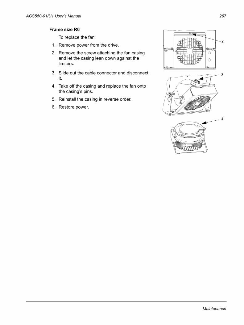
ACS550-01/U1 User’s Manual 267
Frame size R6To replace the fan:
1. Remove power from the drive.
2. Remove the screw attaching the fan casing and let the casing lean down against the limiters.
3. Slide out the cable connector and disconnect it.
4. Take off the casing and replace the fan onto the casing’s pins.
5. Reinstall the casing in reverse order.
6. Restore power.
2
3
4
Maintenance
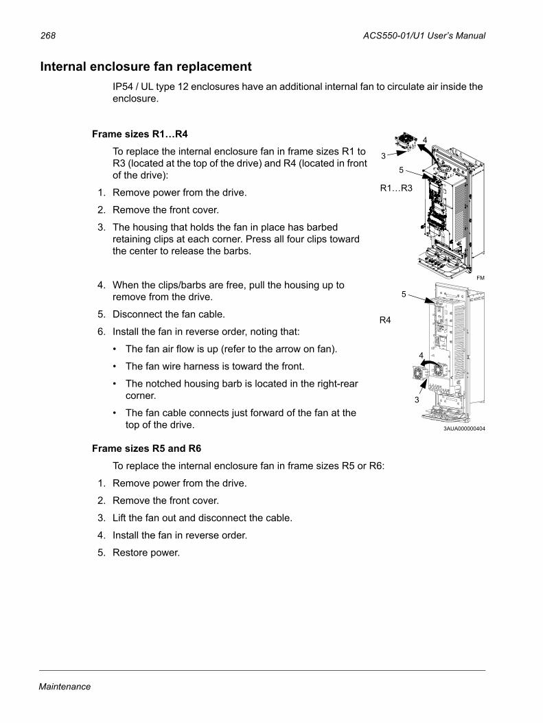
268 ACS550-01/U1 User’s Manual
Internal enclosure fan replacementIP54 / UL type 12 enclosures have an additional internal fan to circulate air inside the enclosure.
Frame sizes R1…R4To replace the internal enclosure fan in frame sizes R1 to R3 (located at the top of the drive) and R4 (located in front of the drive):
1. Remove power from the drive.
2. Remove the front cover.
3. The housing that holds the fan in place has barbed retaining clips at each corner. Press all four clips toward the center to release the barbs.
4. When the clips/barbs are free, pull the housing up to remove from the drive.
5. Disconnect the fan cable.
6. Install the fan in reverse order, noting that:
• The fan air flow is up (refer to the arrow on fan).
• The fan wire harness is toward the front.
• The notched housing barb is located in the right-rear corner.
• The fan cable connects just forward of the fan at the top of the drive.
Frame sizes R5 and R6To replace the internal enclosure fan in frame sizes R5 or R6:
1. Remove power from the drive.
2. Remove the front cover.
3. Lift the fan out and disconnect the cable.
4. Install the fan in reverse order.
5. Restore power.
4
3
5
FM
R1…R3
3AUA000000404
3
4
5
R4
Maintenance
ACS550-01/U1 User’s Manual 269
Capacitors
ReformingThe drive DC link capacitors need to be reformed (re-aged) if the drive has been non-operational for more than one year. Without reforming, capacitors may be damaged when the drive starts to operate. It is therefore recommended to reform the capacitors once a year. See section Serial number on page 13 for how to check the date of manufacture from the serial number shown on the drive labels.
For information on reforming the capacitors, refer to Guide for Capacitor Reforming in ACS50, ACS55, ACS150, ACS310, ACS320, ACS350, ACS550 and ACH550 (3AFE68735190 [English]), available on the Internet (go to www.abb.com and enter the code in the Search field).
ReplacementThe drive intermediate circuit employs several electrolytic capacitors. Their life span is from 35 000…90 000 hours depending on drive loading and ambient temperature. Capacitor life can be prolonged by lowering the ambient temperature.
It is not possible to predict a capacitor failure. Capacitor failure is usually followed by a input power fuse failure or a fault trip. Contact ABB if capacitor failure is suspected. Replacements for frame size R5 and R6 are available from ABB. Do not use other than ABB specified spare parts.
Control panel
CleaningUse a soft damp cloth to clean the control panel. Avoid harsh cleaners which could scratch the display window.
BatteryA battery is only used in Assistant Control Panels that have the clock function available and enabled. The battery keeps the clock operating in memory during power interruptions.
The expected life for the battery is greater than ten years. To remove the battery, use a coin to rotate the battery holder on the back of the control panel. Replace the battery with type CR2032.
Note: The battery is NOT required for any control panel or drive function, except the clock.
Maintenance

270 ACS550-01/U1 User’s Manual
Maintenance
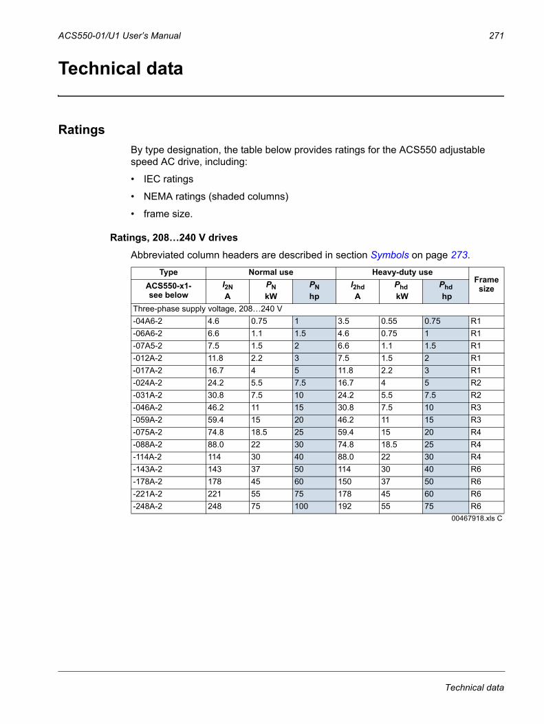
ACS550-01/U1 User’s Manual 271
Technical data
RatingsBy type designation, the table below provides ratings for the ACS550 adjustable speed AC drive, including:
• IEC ratings
• NEMA ratings (shaded columns)
• frame size.
Ratings, 208…240 V drivesAbbreviated column headers are described in section Symbols on page 273.
Type Normal use Heavy-duty use Frame
sizeACS550-x1-see below
I2NA
PNkW
PNhp
I2hd A
Phd kW
Phd hp
Three-phase supply voltage, 208…240 V -04A6-2 4.6 0.75 1 3.5 0.55 0.75 R1-06A6-2 6.6 1.1 1.5 4.6 0.75 1 R1-07A5-2 7.5 1.5 2 6.6 1.1 1.5 R1-012A-2 11.8 2.2 3 7.5 1.5 2 R1-017A-2 16.7 4 5 11.8 2.2 3 R1-024A-2 24.2 5.5 7.5 16.7 4 5 R2-031A-2 30.8 7.5 10 24.2 5.5 7.5 R2-046A-2 46.2 11 15 30.8 7.5 10 R3-059A-2 59.4 15 20 46.2 11 15 R3-075A-2 74.8 18.5 25 59.4 15 20 R4-088A-2 88.0 22 30 74.8 18.5 25 R4-114A-2 114 30 40 88.0 22 30 R4-143A-2 143 37 50 114 30 40 R6-178A-2 178 45 60 150 37 50 R6-221A-2 221 55 75 178 45 60 R6-248A-2 248 75 100 192 55 75 R6
00467918.xls C
Technical data
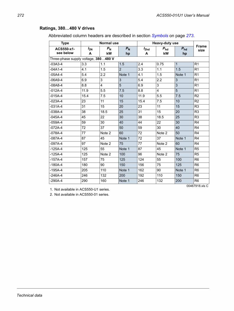
272 ACS550-01/U1 User’s Manual
Ratings, 380…480 V drivesAbbreviated column headers are described in section Symbols on page 273.
Type Normal use Heavy-duty use Frame sizeACS550-x1-
see below I2NA
PNkW
PNhp
I2hd A
Phd kW
Phd hp
Three-phase supply voltage, 380…480 V -03A3-4 3.3 1.1 1.5 2.4 0.75 1 R1-04A1-4 4.1 1.5 2 3.3 1.1 1.5 R1-05A4-4 5.4 2.2 Note 1 4.1 1.5 Note 1 R1-06A9-4 6.9 3 3 5.4 2.2 3 R1-08A8-4 8.8 4 5 6.9 3 3 R1-012A-4 11.9 5.5 7.5 8.8 4 5 R1-015A-4 15.4 7.5 10 11.9 5.5 7.5 R2-023A-4 23 11 15 15.4 7.5 10 R2-031A-4 31 15 20 23 11 15 R3-038A-4 38 18.5 25 31 15 20 R3-045A-4 45 22 30 38 18.5 25 R3-059A-4 59 30 40 44 22 30 R4-072A-4 72 37 50 59 30 40 R4-078A-4 77 Note 2 60 72 Note 2 50 R4-087A-4 87 45 Note 1 72 37 Note 1 R4-097A-4 97 Note 2 75 77 Note 2 60 R4-125A-4 125 55 Note 1 87 45 Note 1 R5-125A-4 125 Note 2 100 96 Note 2 75 R5-157A-4 157 75 125 124 55 100 R6-180A-4 180 90 150 156 75 125 R6-195A-4 205 110 Note 1 162 90 Note 1 R6-246A-4 246 132 200 192 110 150 R6-290A-4 290 160 Note 1 246 132 200 R6
00467918.xls C1. Not available in ACS550-U1 series.2. Not available in ACS550-01 series.
Technical data
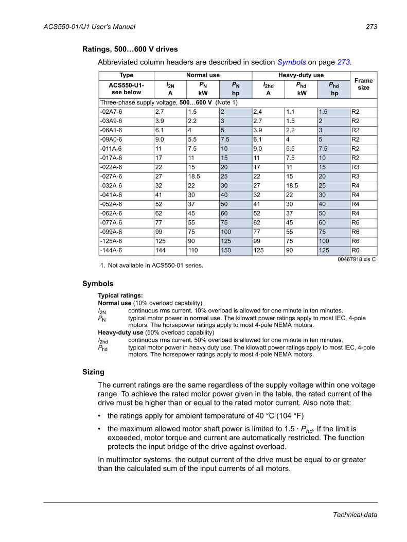
ACS550-01/U1 User’s Manual 273
Ratings, 500…600 V drivesAbbreviated column headers are described in section Symbols on page 273.
Symbols
SizingThe current ratings are the same regardless of the supply voltage within one voltage range. To achieve the rated motor power given in the table, the rated current of the drive must be higher than or equal to the rated motor current. Also note that:
• the ratings apply for ambient temperature of 40 °C (104 °F)
• the maximum allowed motor shaft power is limited to 1.5 · Phd. If the limit is exceeded, motor torque and current are automatically restricted. The function protects the input bridge of the drive against overload.
In multimotor systems, the output current of the drive must be equal to or greater than the calculated sum of the input currents of all motors.
Type Normal use Heavy-duty use Frame sizeACS550-U1-
see below I2NA
PNkW
PNhp
I2hd A
Phd kW
Phd hp
Three-phase supply voltage, 500…600 V (Note 1)-02A7-6 2.7 1.5 2 2.4 1.1 1.5 R2-03A9-6 3.9 2.2 3 2.7 1.5 2 R2-06A1-6 6.1 4 5 3.9 2.2 3 R2-09A0-6 9.0 5.5 7.5 6.1 4 5 R2-011A-6 11 7.5 10 9.0 5.5 7.5 R2-017A-6 17 11 15 11 7.5 10 R2-022A-6 22 15 20 17 11 15 R3-027A-6 27 18.5 25 22 15 20 R3-032A-6 32 22 30 27 18.5 25 R4-041A-6 41 30 40 32 22 30 R4-052A-6 52 37 50 41 30 40 R4-062A-6 62 45 60 52 37 50 R4-077A-6 77 55 75 62 45 60 R6-099A-6 99 75 100 77 55 75 R6-125A-6 125 90 125 99 75 100 R6-144A-6 144 110 150 125 90 125 R6
00467918.xls C1. Not available in ACS550-01 series.
Typical ratings:Normal use (10% overload capability)I2N continuous rms current. 10% overload is allowed for one minute in ten minutes. PN typical motor power in normal use. The kilowatt power ratings apply to most IEC, 4-pole
motors. The horsepower ratings apply to most 4-pole NEMA motors. Heavy-duty use (50% overload capability)I2hd continuous rms current. 50% overload is allowed for one minute in ten minutes.Phd typical motor power in heavy duty use. The kilowatt power ratings apply to most IEC, 4-pole
motors. The horsepower ratings apply to most 4-pole NEMA motors.
Technical data
274 ACS550-01/U1 User’s Manual
DeratingThe load capacity (current and power) decreases for certain situations, as defined below. In such situations, where full motor power is required, oversize the drive so that the derated value provides sufficient capacity.
For example, if your application requires 15.4 A of motor current and a 8 kHz switching frequency, calculate the appropriate drive size requirement as follows:
The minimum size required = 15.4 A / 0.80 = 19.25 AWhere: 0.80 is the derating for 8 kHz switching frequency (see section Switching frequency derating on page 274).
Referring to I2N in the ratings tables (starting from page 271), the following drives exceed the I2N requirement of 19.25 A: ACS550-x1-023A-4, or ACS550-x1-024A-2.
Temperature derating
In the temperature range +40 °C…50 °C (+104 °F…122 °F), the rated output current is decreased 1% for every 1 °C (1.8 °F) above +40 °C (+104 °F). Calculate the output current by multiplying the current given in the rating table by the derating factor.
Example If the ambient temperature is 50 °C (+122 °F), the derating factor is 100% - 1%/°C · 10 °C = 90% or 0.90. The output current is then 0.90 · I2N or 0.90 · I2hd.
Altitude derating
In altitudes 1000…4000 m (3300…13,200 ft) above sea level, the derating is 1% for every 100 m (330 ft). If the installation site is higher than 2000 m (6600 ft) above sea level, please contact your local ABB distributor or office for further information.
Single phase supply derating
For 208…240 V series drives, a single phase supply can be used. In that case, the derating is 50%.
Switching frequency derating
When using the 8 kHz switching frequency (parameter 2606),
• derate all rated currents and powers (including drive's overload currents) to 80%.
When using the 12 kHz switching frequency (parameter 2606),
• derate all rated currents and powers (including drive's overload currents) to 65% (to 50% for 600 V, R4 frame sizes, that is for ACS550-U1-032A-6 … ACS550-U1-062A-6),
• derate ambient temperature maximum to 30 °C (86 °F).
• Note: The continuous maximum current is limited to I2hd.
Note: Setting parameter 2607 SWITCH FREQ CTRL = 1 (ON) allows the drive to reduce the switching frequency if/when the drive’s internal temperature exceeds 80 °C (with 12 kHz switching frequency) or 90 °C (with 8 kHz switching frequency). See the parameter description for 2607 for details.
Technical data
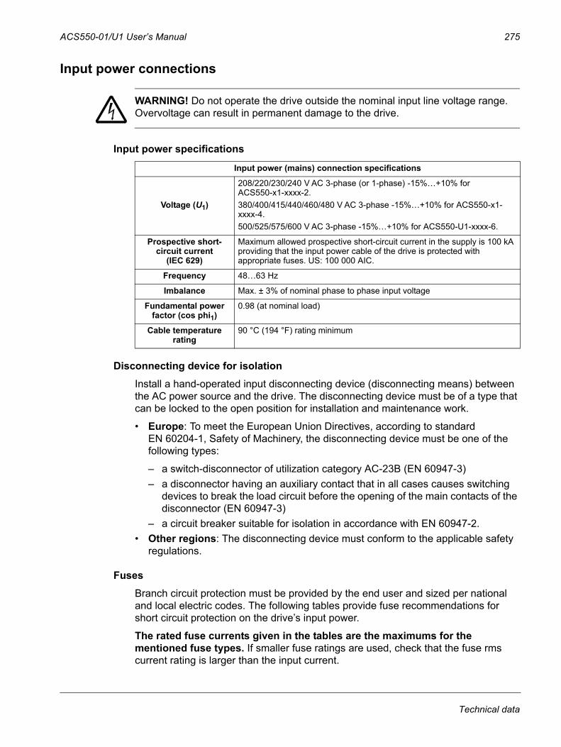
ACS550-01/U1 User’s Manual 275
Input power connections
WARNING! Do not operate the drive outside the nominal input line voltage range. Overvoltage can result in permanent damage to the drive.
Input power specifications
Disconnecting device for isolationInstall a hand-operated input disconnecting device (disconnecting means) between the AC power source and the drive. The disconnecting device must be of a type that can be locked to the open position for installation and maintenance work.
• Europe: To meet the European Union Directives, according to standard EN 60204-1, Safety of Machinery, the disconnecting device must be one of the following types:
– a switch-disconnector of utilization category AC-23B (EN 60947-3)– a disconnector having an auxiliary contact that in all cases causes switching
devices to break the load circuit before the opening of the main contacts of the disconnector (EN 60947-3)
– a circuit breaker suitable for isolation in accordance with EN 60947-2. • Other regions: The disconnecting device must conform to the applicable safety
regulations.
FusesBranch circuit protection must be provided by the end user and sized per national and local electric codes. The following tables provide fuse recommendations for short circuit protection on the drive’s input power.
The rated fuse currents given in the tables are the maximums for the mentioned fuse types. If smaller fuse ratings are used, check that the fuse rms current rating is larger than the input current.
Input power (mains) connection specifications
Voltage (U1)
208/220/230/240 V AC 3-phase (or 1-phase) -15%…+10% for ACS550-x1-xxxx-2.380/400/415/440/460/480 V AC 3-phase -15%…+10% for ACS550-x1-xxxx-4.500/525/575/600 V AC 3-phase -15%…+10% for ACS550-U1-xxxx-6.
Prospective short-circuit current
(IEC 629)
Maximum allowed prospective short-circuit current in the supply is 100 kA providing that the input power cable of the drive is protected with appropriate fuses. US: 100 000 AIC.
Frequency 48…63 Hz
Imbalance Max. ± 3% of nominal phase to phase input voltage
Fundamental power factor (cos phi1)
0.98 (at nominal load)
Cable temperature rating
90 °C (194 °F) rating minimum
Technical data
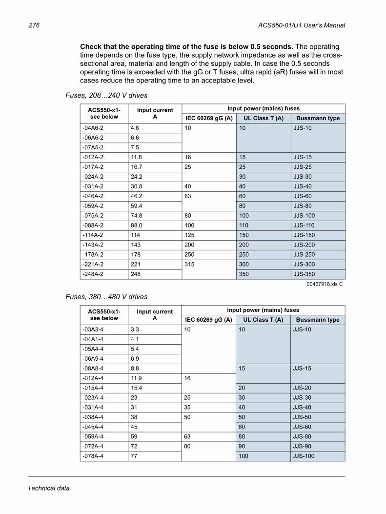
276 ACS550-01/U1 User’s Manual
Check that the operating time of the fuse is below 0.5 seconds. The operating time depends on the fuse type, the supply network impedance as well as the cross-sectional area, material and length of the supply cable. In case the 0.5 seconds operating time is exceeded with the gG or T fuses, ultra rapid (aR) fuses will in most cases reduce the operating time to an acceptable level.
Fuses, 208…240 V drives
Fuses, 380…480 V drives
ACS550-x1-see below
Input currentA
Input power (mains) fusesIEC 60269 gG (A) UL Class T (A) Bussmann type
-04A6-2 4.6 10 10 JJS-10
-06A6-2 6.6
-07A5-2 7.5
-012A-2 11.8 16 15 JJS-15
-017A-2 16.7 25 25 JJS-25
-024A-2 24.2 30 JJS-30
-031A-2 30.8 40 40 JJS-40
-046A-2 46.2 63 60 JJS-60
-059A-2 59.4 80 JJS-80
-075A-2 74.8 80 100 JJS-100
-088A-2 88.0 100 110 JJS-110
-114A-2 114 125 150 JJS-150
-143A-2 143 200 200 JJS-200
-178A-2 178 250 250 JJS-250
-221A-2 221 315 300 JJS-300
-248A-2 248 350 JJS-350
00467918.xls C
ACS550-x1-see below
Input currentA
Input power (mains) fusesIEC 60269 gG (A) UL Class T (A) Bussmann type
-03A3-4 3.3 10 10 JJS-10
-04A1-4 4.1
-05A4-4 5.4
-06A9-4 6.9
-08A8-4 8.8 15 JJS-15
-012A-4 11.9 16
-015A-4 15.4 20 JJS-20
-023A-4 23 25 30 JJS-30
-031A-4 31 35 40 JJS-40
-038A-4 38 50 50 JJS-50
-045A-4 45 60 JJS-60
-059A-4 59 63 80 JJS-80
-072A-4 72 80 90 JJS-90
-078A-4 77 100 JJS-100
Technical data
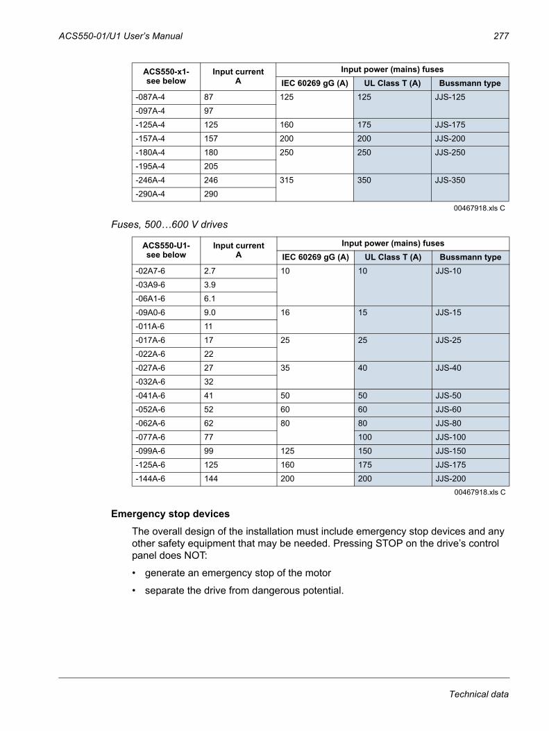
ACS550-01/U1 User’s Manual 277
Fuses, 500…600 V drives
Emergency stop devicesThe overall design of the installation must include emergency stop devices and any other safety equipment that may be needed. Pressing STOP on the drive’s control panel does NOT:
• generate an emergency stop of the motor
• separate the drive from dangerous potential.
-087A-4 87 125 125 JJS-125
-097A-4 97
-125A-4 125 160 175 JJS-175
-157A-4 157 200 200 JJS-200
-180A-4 180 250 250 JJS-250
-195A-4 205
-246A-4 246 315 350 JJS-350
-290A-4 290
00467918.xls C
ACS550-U1-see below
Input currentA
Input power (mains) fusesIEC 60269 gG (A) UL Class T (A) Bussmann type
-02A7-6 2.7 10 10 JJS-10
-03A9-6 3.9
-06A1-6 6.1
-09A0-6 9.0 16 15 JJS-15
-011A-6 11
-017A-6 17 25 25 JJS-25
-022A-6 22
-027A-6 27 35 40 JJS-40
-032A-6 32
-041A-6 41 50 50 JJS-50
-052A-6 52 60 60 JJS-60
-062A-6 62 80 80 JJS-80
-077A-6 77 100 JJS-100
-099A-6 99 125 150 JJS-150
-125A-6 125 160 175 JJS-175
-144A-6 144 200 200 JJS-20000467918.xls C
ACS550-x1-see below
Input currentA
Input power (mains) fusesIEC 60269 gG (A) UL Class T (A) Bussmann type
Technical data
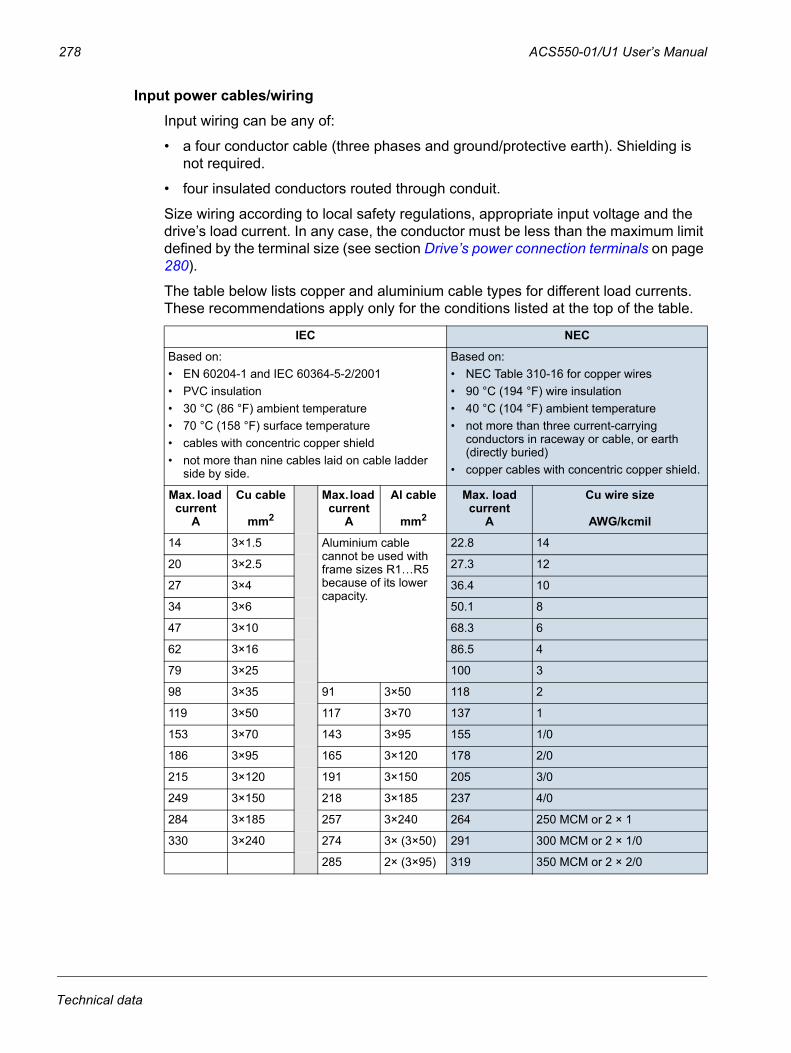
278 ACS550-01/U1 User’s Manual
Input power cables/wiringInput wiring can be any of:
• a four conductor cable (three phases and ground/protective earth). Shielding is not required.
• four insulated conductors routed through conduit.
Size wiring according to local safety regulations, appropriate input voltage and the drive’s load current. In any case, the conductor must be less than the maximum limit defined by the terminal size (see section Drive’s power connection terminals on page 280).
The table below lists copper and aluminium cable types for different load currents. These recommendations apply only for the conditions listed at the top of the table.
IEC NEC
Based on:• EN 60204-1 and IEC 60364-5-2/2001• PVC insulation• 30 °C (86 °F) ambient temperature• 70 °C (158 °F) surface temperature• cables with concentric copper shield• not more than nine cables laid on cable ladder
side by side.
Based on:• NEC Table 310-16 for copper wires• 90 °C (194 °F) wire insulation• 40 °C (104 °F) ambient temperature• not more than three current-carrying
conductors in raceway or cable, or earth (directly buried)
• copper cables with concentric copper shield.
Max. load current
A
Cu cable
mm2
Max. load current
A
Al cable
mm2
Max. load current
A
Cu wire size
AWG/kcmil
14 3×1.5 Aluminium cable cannot be used with frame sizes R1…R5 because of its lower capacity.
22.8 14
20 3×2.5 27.3 12
27 3×4 36.4 10
34 3×6 50.1 8
47 3×10 68.3 6
62 3×16 86.5 4
79 3×25 100 3
98 3×35 91 3×50 118 2
119 3×50 117 3×70 137 1
153 3×70 143 3×95 155 1/0
186 3×95 165 3×120 178 2/0
215 3×120 191 3×150 205 3/0
249 3×150 218 3×185 237 4/0
284 3×185 257 3×240 264 250 MCM or 2 × 1
330 3×240 274 3× (3×50) 291 300 MCM or 2 × 1/0
285 2× (3×95) 319 350 MCM or 2 × 2/0
Technical data
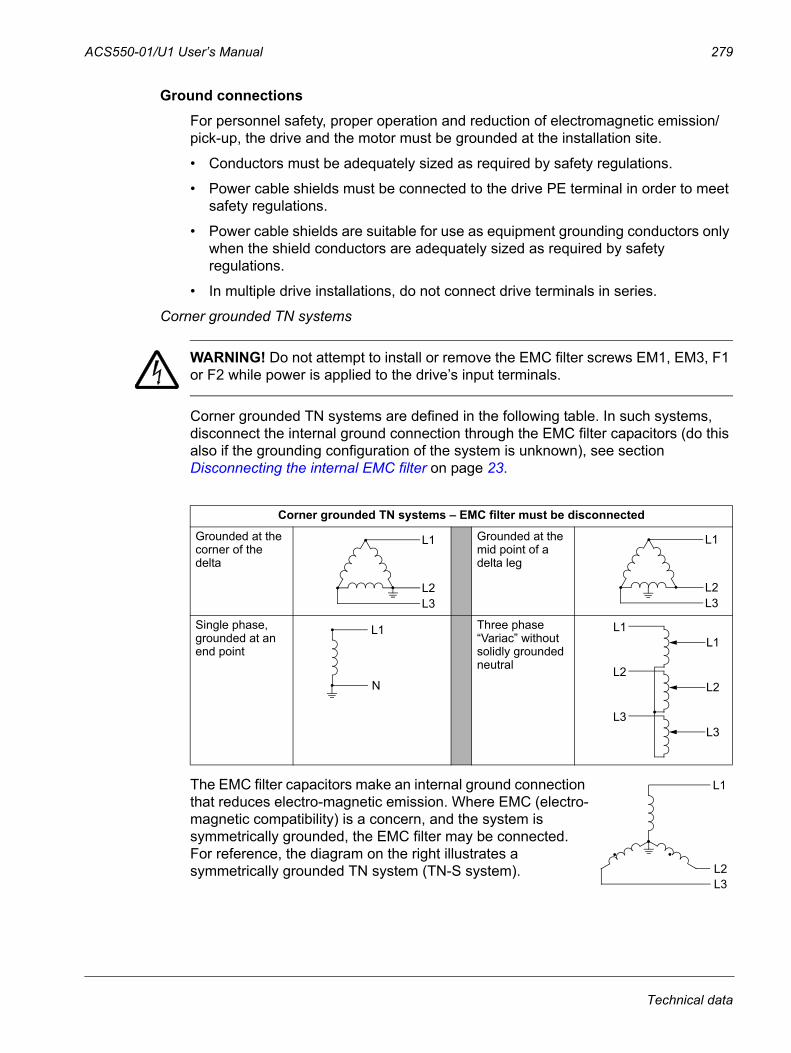
ACS550-01/U1 User’s Manual 279
Ground connectionsFor personnel safety, proper operation and reduction of electromagnetic emission/pick-up, the drive and the motor must be grounded at the installation site.
• Conductors must be adequately sized as required by safety regulations.
• Power cable shields must be connected to the drive PE terminal in order to meet safety regulations.
• Power cable shields are suitable for use as equipment grounding conductors only when the shield conductors are adequately sized as required by safety regulations.
• In multiple drive installations, do not connect drive terminals in series.
Corner grounded TN systems
WARNING! Do not attempt to install or remove the EMC filter screws EM1, EM3, F1 or F2 while power is applied to the drive’s input terminals.
Corner grounded TN systems are defined in the following table. In such systems, disconnect the internal ground connection through the EMC filter capacitors (do this also if the grounding configuration of the system is unknown), see section Disconnecting the internal EMC filter on page 23.
The EMC filter capacitors make an internal ground connection that reduces electro-magnetic emission. Where EMC (electro-magnetic compatibility) is a concern, and the system is symmetrically grounded, the EMC filter may be connected. For reference, the diagram on the right illustrates a symmetrically grounded TN system (TN-S system).
Corner grounded TN systems – EMC filter must be disconnected
Grounded at the corner of the delta
Grounded at the mid point of a delta leg
Single phase, grounded at an end point
Three phase “Variac” without solidly grounded neutral
L1
L2L3
L1
L2L3
L1
N
L1L1
L2L2
L3L3
L1
L2L3
Technical data
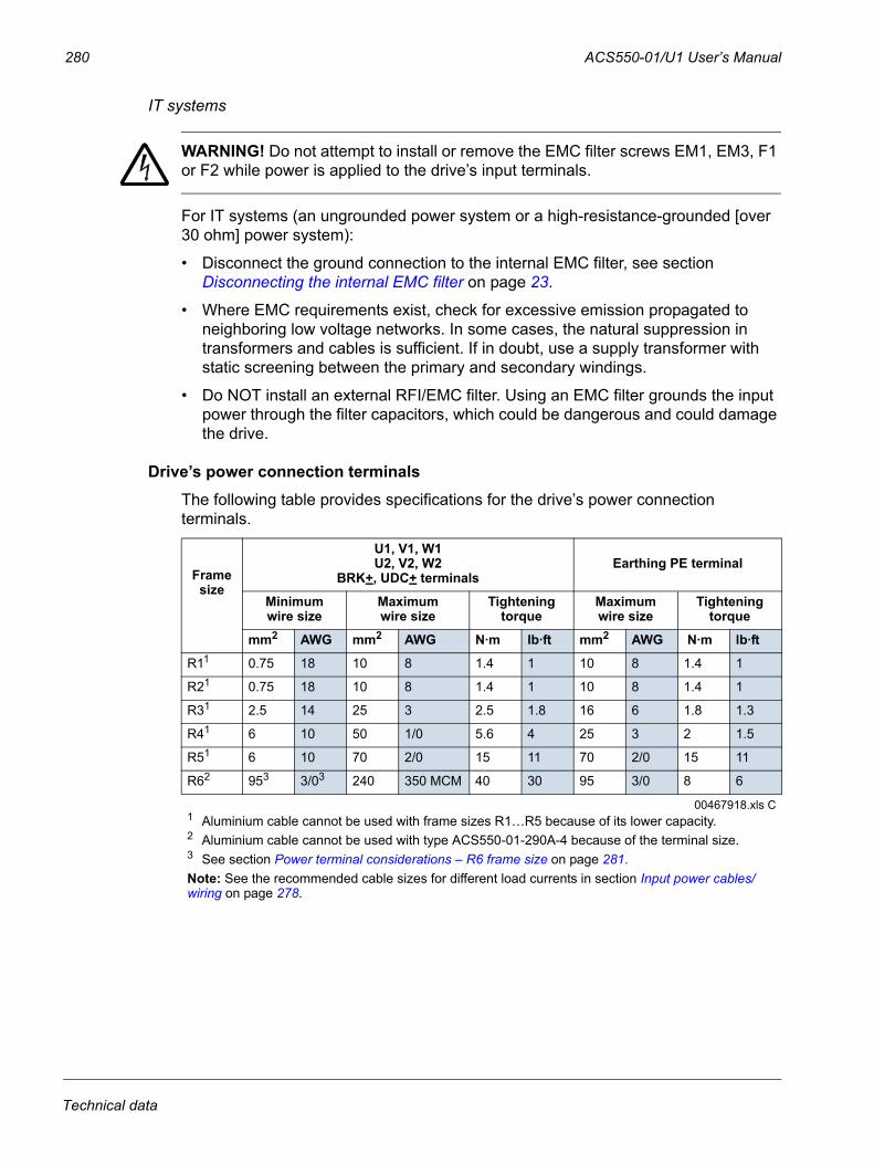
280 ACS550-01/U1 User’s Manual
IT systems
WARNING! Do not attempt to install or remove the EMC filter screws EM1, EM3, F1 or F2 while power is applied to the drive’s input terminals.
For IT systems (an ungrounded power system or a high-resistance-grounded [over 30 ohm] power system):
• Disconnect the ground connection to the internal EMC filter, see section Disconnecting the internal EMC filter on page 23.
• Where EMC requirements exist, check for excessive emission propagated to neighboring low voltage networks. In some cases, the natural suppression in transformers and cables is sufficient. If in doubt, use a supply transformer with static screening between the primary and secondary windings.
• Do NOT install an external RFI/EMC filter. Using an EMC filter grounds the input power through the filter capacitors, which could be dangerous and could damage the drive.
Drive’s power connection terminalsThe following table provides specifications for the drive’s power connection terminals.
Frame size
U1, V1, W1U2, V2, W2
BRK+, UDC+ terminalsEarthing PE terminal
Minimumwire size
Maximumwire size
Tightening torque
Maximumwire size
Tightening torque
mm2 AWG mm2 AWG N·m lb·ft mm2 AWG N·m lb·ft
R11 0.75 18 10 8 1.4 1 10 8 1.4 1
R21 0.75 18 10 8 1.4 1 10 8 1.4 1
R31 2.5 14 25 3 2.5 1.8 16 6 1.8 1.3
R41 6 10 50 1/0 5.6 4 25 3 2 1.5
R51 6 10 70 2/0 15 11 70 2/0 15 11
R62 953 3/03 240 350 MCM 40 30 95 3/0 8 6
00467918.xls C1 Aluminium cable cannot be used with frame sizes R1…R5 because of its lower capacity.2 Aluminium cable cannot be used with type ACS550-01-290A-4 because of the terminal size.3 See section Power terminal considerations – R6 frame size on page 281.Note: See the recommended cable sizes for different load currents in section Input power cables/wiring on page 278.
Technical data
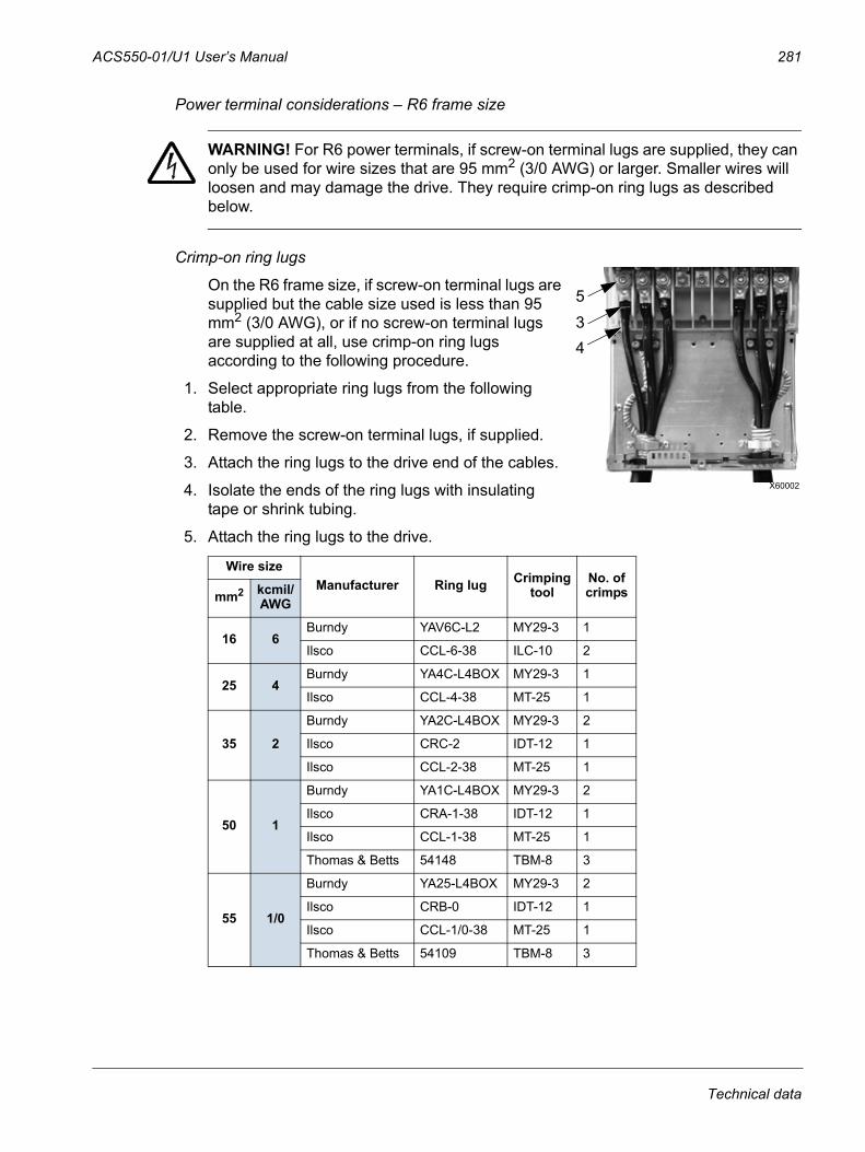
ACS550-01/U1 User’s Manual 281
Power terminal considerations – R6 frame size
WARNING! For R6 power terminals, if screw-on terminal lugs are supplied, they can only be used for wire sizes that are 95 mm2 (3/0 AWG) or larger. Smaller wires will loosen and may damage the drive. They require crimp-on ring lugs as described below.
Crimp-on ring lugs On the R6 frame size, if screw-on terminal lugs are supplied but the cable size used is less than 95 mm2 (3/0 AWG), or if no screw-on terminal lugs are supplied at all, use crimp-on ring lugs according to the following procedure.
1. Select appropriate ring lugs from the following table.
2. Remove the screw-on terminal lugs, if supplied.
3. Attach the ring lugs to the drive end of the cables.
4. Isolate the ends of the ring lugs with insulating tape or shrink tubing.
5. Attach the ring lugs to the drive.
Wire sizeManufacturer Ring lug Crimping
toolNo. of crimpsmm2 kcmil/
AWG
16 6Burndy YAV6C-L2 MY29-3 1
Ilsco CCL-6-38 ILC-10 2
25 4Burndy YA4C-L4BOX MY29-3 1
Ilsco CCL-4-38 MT-25 1
35 2
Burndy YA2C-L4BOX MY29-3 2
Ilsco CRC-2 IDT-12 1
Ilsco CCL-2-38 MT-25 1
50 1
Burndy YA1C-L4BOX MY29-3 2
Ilsco CRA-1-38 IDT-12 1
Ilsco CCL-1-38 MT-25 1
Thomas & Betts 54148 TBM-8 3
55 1/0
Burndy YA25-L4BOX MY29-3 2
Ilsco CRB-0 IDT-12 1
Ilsco CCL-1/0-38 MT-25 1
Thomas & Betts 54109 TBM-8 3
X60002
435
Technical data
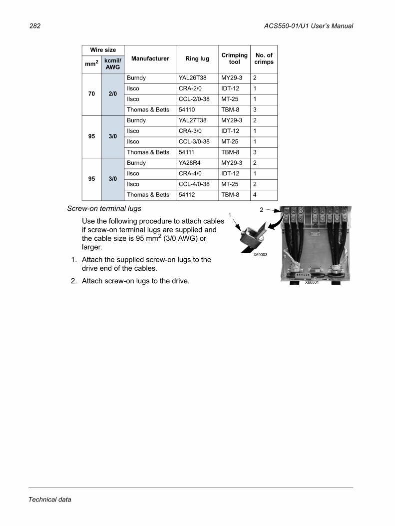
282 ACS550-01/U1 User’s Manual
Screw-on terminal lugs
Use the following procedure to attach cables if screw-on terminal lugs are supplied and the cable size is 95 mm2 (3/0 AWG) or larger.
1. Attach the supplied screw-on lugs to the drive end of the cables.
2. Attach screw-on lugs to the drive.
70 2/0
Burndy YAL26T38 MY29-3 2
Ilsco CRA-2/0 IDT-12 1
Ilsco CCL-2/0-38 MT-25 1
Thomas & Betts 54110 TBM-8 3
95 3/0
Burndy YAL27T38 MY29-3 2
Ilsco CRA-3/0 IDT-12 1
Ilsco CCL-3/0-38 MT-25 1
Thomas & Betts 54111 TBM-8 3
95 3/0
Burndy YA28R4 MY29-3 2
Ilsco CRA-4/0 IDT-12 1
Ilsco CCL-4/0-38 MT-25 2
Thomas & Betts 54112 TBM-8 4
Wire sizeManufacturer Ring lug Crimping
toolNo. of crimpsmm2 kcmil/
AWG
X60001
X60003
12
Technical data
ACS550-01/U1 User’s Manual 283
Motor connections
WARNING! Never connect line power to the drive output terminals: U2, V2 or W2. Line voltage applied to the output can result in permanent damage to the drive. If frequent bypassing is required, use mechanically interlocked switches or contactors.
WARNING! Do not connect any motor with a nominal voltage less than one half of the drive’s nominal input voltage.
WARNING! Disconnect the drive before conducting any voltage tolerance (Hi-Pot) test or insulation resistance (Megger) test on the motor or motor cables. Do not conduct these tests on the drive.
Motor connection specifications
Motor cable lengthsMaximum motor cable lengths for 400 V and 600 V drives are given in the sections below.
In multimotor systems, the calculated sum of all motor cable lengths must not exceed the maximum motor cable length given in the appropriate table below.
Motor connection specifications
Voltage (U2) 0…U1, 3-phase symmetrical, Umax at the field weakening point
Frequency 0…500 Hz
Frequency resolution 0.01 Hz
Current See section Ratings on page 271.
Field weakening point 10…500 Hz
Switching frequency
Selectable. See the availability in the table below.
Cable temperature rating 90 °C (194 °F) rating minimum.
Maximum motor cable length
See section Motor cable lengths on page 283.
1, 2, 4 and 8 kHz 12 kHz208…240 V All types Frame sizes R1…R4 in scalar
control mode380…480 V All types Frame sizes R1…R4 (except
ACS550-01-097A-4) in scalar control mode
500…600 V All types Frame sizes R2…R4 in scalar control mode
Technical data
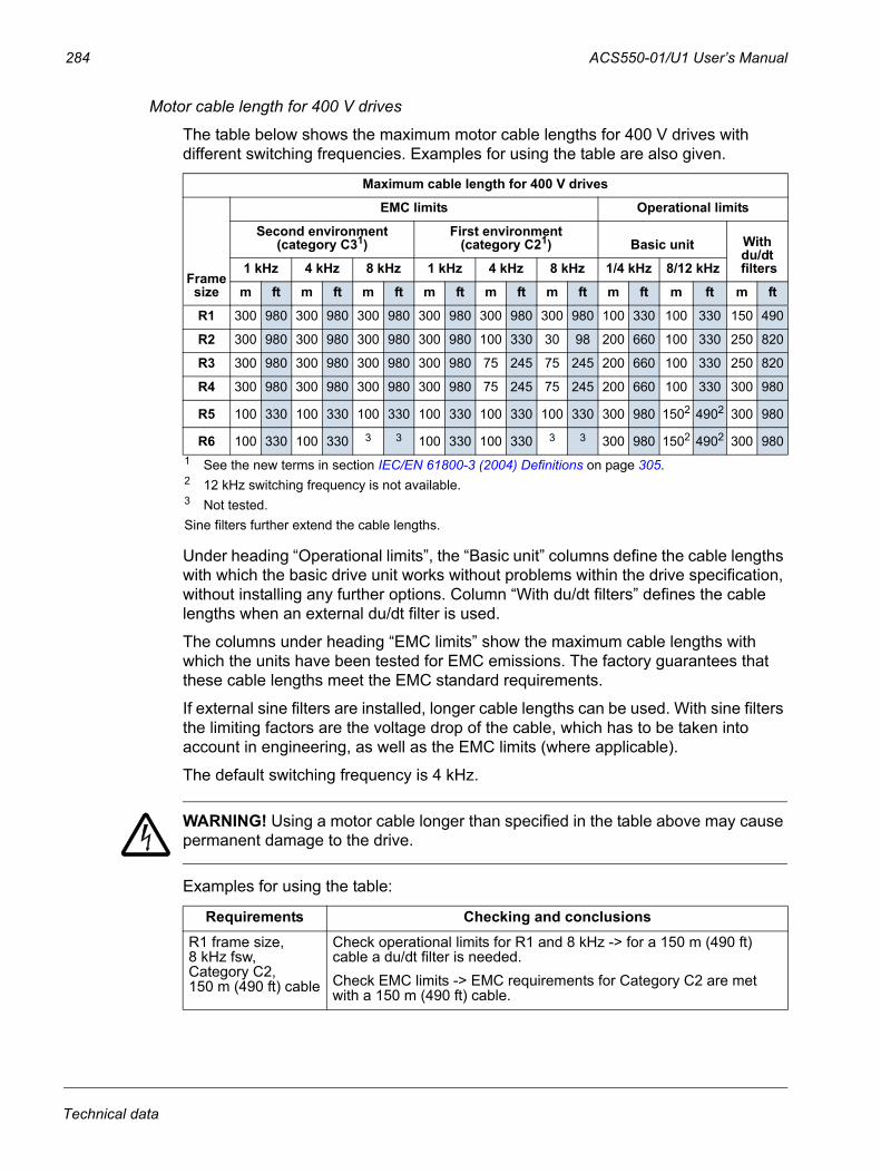
284 ACS550-01/U1 User’s Manual
Motor cable length for 400 V drives
The table below shows the maximum motor cable lengths for 400 V drives with different switching frequencies. Examples for using the table are also given.
Under heading “Operational limits”, the “Basic unit” columns define the cable lengths with which the basic drive unit works without problems within the drive specification, without installing any further options. Column “With du/dt filters” defines the cable lengths when an external du/dt filter is used.
The columns under heading “EMC limits” show the maximum cable lengths with which the units have been tested for EMC emissions. The factory guarantees that these cable lengths meet the EMC standard requirements.
If external sine filters are installed, longer cable lengths can be used. With sine filters the limiting factors are the voltage drop of the cable, which has to be taken into account in engineering, as well as the EMC limits (where applicable).
The default switching frequency is 4 kHz.
WARNING! Using a motor cable longer than specified in the table above may cause permanent damage to the drive.
Examples for using the table:
Maximum cable length for 400 V drives
Frame size
EMC limits Operational limits
Second environment(category C31)
First environment(category C21) Basic unit With
du/dt filters1 kHz 4 kHz 8 kHz 1 kHz 4 kHz 8 kHz 1/4 kHz 8/12 kHz
m ft m ft m ft m ft m ft m ft m ft m ft m ft
R1 300 980 300 980 300 980 300 980 300 980 300 980 100 330 100 330 150 490
R2 300 980 300 980 300 980 300 980 100 330 30 98 200 660 100 330 250 820
R3 300 980 300 980 300 980 300 980 75 245 75 245 200 660 100 330 250 820
R4 300 980 300 980 300 980 300 980 75 245 75 245 200 660 100 330 300 980
R5 100 330 100 330 100 330 100 330 100 330 100 330 300 980 1502 4902 300 980
R6 100 330 100 330 3 3 100 330 100 330 3 3 300 980 1502 4902 300 9801 See the new terms in section IEC/EN 61800-3 (2004) Definitions on page 305.2 12 kHz switching frequency is not available.3 Not tested.Sine filters further extend the cable lengths.
Requirements Checking and conclusionsR1 frame size,8 kHz fsw,Category C2,150 m (490 ft) cable
Check operational limits for R1 and 8 kHz -> for a 150 m (490 ft) cable a du/dt filter is needed.Check EMC limits -> EMC requirements for Category C2 are met with a 150 m (490 ft) cable.
Technical data
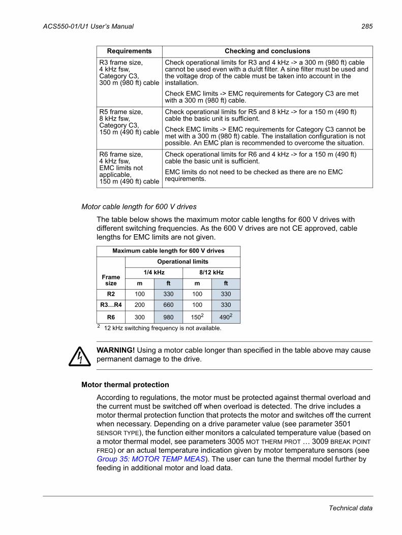
ACS550-01/U1 User’s Manual 285
Motor cable length for 600 V drives
The table below shows the maximum motor cable lengths for 600 V drives with different switching frequencies. As the 600 V drives are not CE approved, cable lengths for EMC limits are not given.
WARNING! Using a motor cable longer than specified in the table above may cause permanent damage to the drive.
Motor thermal protectionAccording to regulations, the motor must be protected against thermal overload and the current must be switched off when overload is detected. The drive includes a motor thermal protection function that protects the motor and switches off the current when necessary. Depending on a drive parameter value (see parameter 3501 SENSOR TYPE), the function either monitors a calculated temperature value (based on a motor thermal model, see parameters 3005 MOT THERM PROT … 3009 BREAK POINT FREQ) or an actual temperature indication given by motor temperature sensors (see Group 35: MOTOR TEMP MEAS). The user can tune the thermal model further by feeding in additional motor and load data.
R3 frame size,4 kHz fsw, Category C3,300 m (980 ft) cable
Check operational limits for R3 and 4 kHz -> a 300 m (980 ft) cable cannot be used even with a du/dt filter. A sine filter must be used and the voltage drop of the cable must be taken into account in the installation.Check EMC limits -> EMC requirements for Category C3 are met with a 300 m (980 ft) cable.
R5 frame size,8 kHz fsw,Category C3,150 m (490 ft) cable
Check operational limits for R5 and 8 kHz -> for a 150 m (490 ft) cable the basic unit is sufficient.Check EMC limits -> EMC requirements for Category C3 cannot be met with a 300 m (980 ft) cable. The installation configuration is not possible. An EMC plan is recommended to overcome the situation.
R6 frame size,4 kHz fsw,EMC limits not applicable,150 m (490 ft) cable
Check operational limits for R6 and 4 kHz -> for a 150 m (490 ft) cable the basic unit is sufficient.EMC limits do not need to be checked as there are no EMC requirements.
Maximum cable length for 600 V drives
Frame size
Operational limits
1/4 kHz 8/12 kHz
m ft m ft
R2 100 330 100 330
R3…R4 200 660 100 330
R6 300 980 1502 4902
2 12 kHz switching frequency is not available.
Requirements Checking and conclusions
Technical data
286 ACS550-01/U1 User’s Manual
The most common temperature sensors are:
• motor sizes IEC180…225: thermal switch (e.g. Klixon)
• motor sizes IEC200…250 and larger: PTC or PT100.
Ground fault protectionACS550 internal fault logic detects ground faults in the drive, motor, or motor cable. This fault logic:
• is NOT a personal safety or fire protection feature
• can be disabled using parameter 3017 EARTH FAULT
Note: Disabling earth fault (ground fault) may void the warranty.
• could be tripped by leakage currents (input power to ground) associated with long high capacitance motor cables.
Grounding and routing
Motor cable shielding
Motor cables require shielding using conduit, armored cable or shielded cable.
• Conduit – When using conduit:
– Bridge joints with a ground conductor bonded to the conduit on each side of the joint.
– Bond conduit run to the drive enclosure.– Use a separate conduit run for motor cables (also separate input power and
control cables).– Use a separate conduit run for each drive.
• Armored cable – When using armored cable:
– Use six-conductor (3 phases and 3 grounds), type MC continuous corrugated aluminium armor cable with symmetrical grounds.
– Armored motor cable can share a cable tray with input power cables, but not with control cables.
• Shielded cable – For shielded cable details, see section Motor cable requirements for CE & C-Tick compliance on page 287.
Grounding
See section Ground connections on page 279.
For CE compliant installations and installations where EMC emissions must be minimized, see section Effective motor cable shields on page 288.
Drive’s motor connection terminalsThe drive’s motor and input power terminals have the same specifications. See section Drive’s power connection terminals on page 280.
Technical data
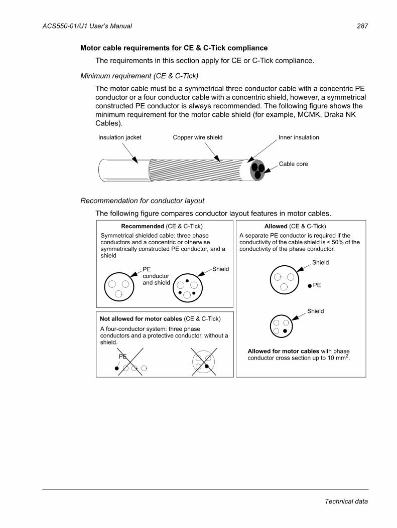
ACS550-01/U1 User’s Manual 287
Motor cable requirements for CE & C-Tick complianceThe requirements in this section apply for CE or C-Tick compliance.
Minimum requirement (CE & C-Tick)
The motor cable must be a symmetrical three conductor cable with a concentric PE conductor or a four conductor cable with a concentric shield, however, a symmetrical constructed PE conductor is always recommended. The following figure shows the minimum requirement for the motor cable shield (for example, MCMK, Draka NK Cables).
Recommendation for conductor layout
The following figure compares conductor layout features in motor cables.
Insulation jacket Copper wire shield
Cable core
Inner insulation
Symmetrical shielded cable: three phase conductors and a concentric or otherwise symmetrically constructed PE conductor, and a shield
Recommended (CE & C-Tick)
PE conductor and shield
A separate PE conductor is required if the conductivity of the cable shield is < 50% of the conductivity of the phase conductor.
Not allowed for motor cables (CE & C-Tick)Shield
PE
PE
Allowed for motor cables with phase conductor cross section up to 10 mm2.
A four-conductor system: three phase conductors and a protective conductor, without a shield.
Allowed (CE & C-Tick)
ShieldShield
Technical data
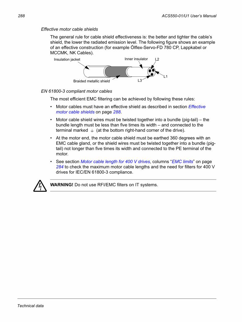
288 ACS550-01/U1 User’s Manual
Effective motor cable shields
The general rule for cable shield effectiveness is: the better and tighter the cable’s shield, the lower the radiated emission level. The following figure shows an example of an effective construction (for example Ölflex-Servo-FD 780 CP, Lappkabel or MCCMK, NK Cables).
EN 61800-3 compliant motor cables
The most efficient EMC filtering can be achieved by following these rules:
• Motor cables must have an effective shield as described in section Effective motor cable shields on page 288.
• Motor cable shield wires must be twisted together into a bundle (pig-tail) – the bundle length must be less than five times its width – and connected to the terminal marked (at the bottom right-hand corner of the drive).
• At the motor end, the motor cable shield must be earthed 360 degrees with an EMC cable gland, or the shield wires must be twisted together into a bundle (pig-tail) not longer than five times its width and connected to the PE terminal of the motor.
• See section Motor cable length for 400 V drives, columns “EMC limits” on page 284 to check the maximum motor cable lengths and the need for filters for 400 V drives for IEC/EN 61800-3 compliance.
WARNING! Do not use RFI/EMC filters on IT systems.
Insulation jacket
Braided metallic shield
Inner insulator
L1
L2
L3
Technical data
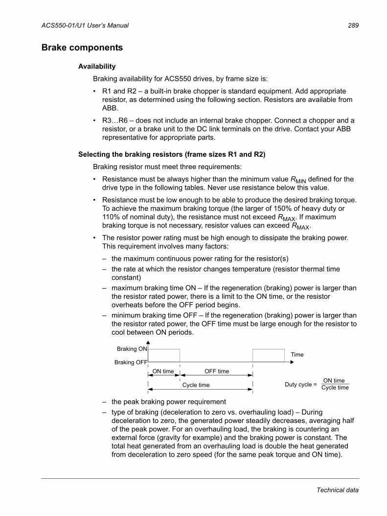
ACS550-01/U1 User’s Manual 289
Brake components
AvailabilityBraking availability for ACS550 drives, by frame size is:
• R1 and R2 – a built-in brake chopper is standard equipment. Add appropriate resistor, as determined using the following section. Resistors are available from ABB.
• R3…R6 – does not include an internal brake chopper. Connect a chopper and a resistor, or a brake unit to the DC link terminals on the drive. Contact your ABB representative for appropriate parts.
Selecting the braking resistors (frame sizes R1 and R2)Braking resistor must meet three requirements:
• Resistance must be always higher than the minimum value RMIN defined for the drive type in the following tables. Never use resistance below this value.
• Resistance must be low enough to be able to produce the desired braking torque. To achieve the maximum braking torque (the larger of 150% of heavy duty or 110% of nominal duty), the resistance must not exceed RMAX. If maximum braking torque is not necessary, resistor values can exceed RMAX.
• The resistor power rating must be high enough to dissipate the braking power. This requirement involves many factors:
– the maximum continuous power rating for the resistor(s)– the rate at which the resistor changes temperature (resistor thermal time
constant)– maximum braking time ON – If the regeneration (braking) power is larger than
the resistor rated power, there is a limit to the ON time, or the resistor overheats before the OFF period begins.
– minimum braking time OFF – If the regeneration (braking) power is larger than the resistor rated power, the OFF time must be large enough for the resistor to cool between ON periods.
– the peak braking power requirement– type of braking (deceleration to zero vs. overhauling load) – During
deceleration to zero, the generated power steadily decreases, averaging half of the peak power. For an overhauling load, the braking is countering an external force (gravity for example) and the braking power is constant. The total heat generated from an overhauling load is double the heat generated from deceleration to zero speed (for the same peak torque and ON time).
TimeBraking ON
Braking OFFON time OFF time
Cycle time Cycle timeON timeDuty cycle =
Technical data
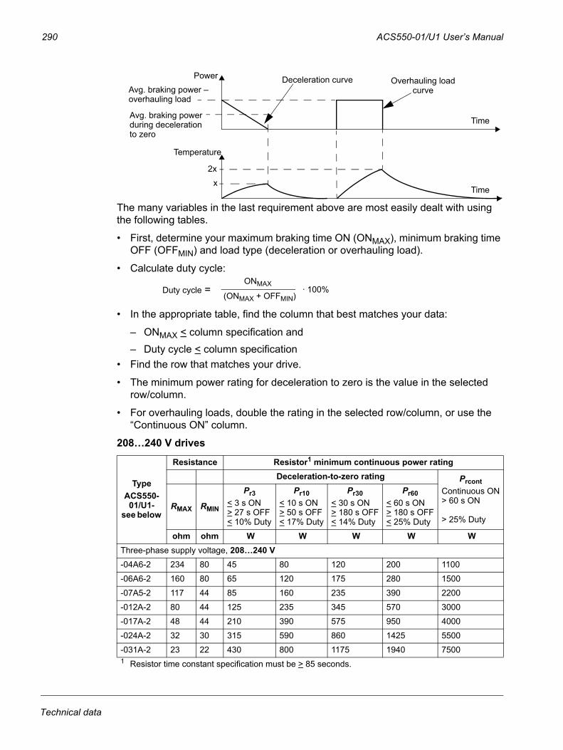
290 ACS550-01/U1 User’s Manual
The many variables in the last requirement above are most easily dealt with using the following tables.
• First, determine your maximum braking time ON (ONMAX), minimum braking time OFF (OFFMIN) and load type (deceleration or overhauling load).
• Calculate duty cycle:
• In the appropriate table, find the column that best matches your data:
– ONMAX < column specification and– Duty cycle < column specification
• Find the row that matches your drive.
• The minimum power rating for deceleration to zero is the value in the selected row/column.
• For overhauling loads, double the rating in the selected row/column, or use the “Continuous ON” column.
208…240 V drives
TypeACS550-01/U1-
see below
Resistance Resistor1 minimum continuous power ratingDeceleration-to-zero rating Prcont
Continuous ON> 60 s ON
> 25% DutyRMAX RMIN
Pr3< 3 s ON> 27 s OFF< 10% Duty
Pr10< 10 s ON> 50 s OFF< 17% Duty
Pr30< 30 s ON> 180 s OFF< 14% Duty
Pr60< 60 s ON> 180 s OFF< 25% Duty
ohm ohm W W W W WThree-phase supply voltage, 208…240 V
-04A6-2 234 80 45 80 120 200 1100
-06A6-2 160 80 65 120 175 280 1500
-07A5-2 117 44 85 160 235 390 2200
-012A-2 80 44 125 235 345 570 3000
-017A-2 48 44 210 390 575 950 4000
-024A-2 32 30 315 590 860 1425 5500
-031A-2 23 22 430 800 1175 1940 75001 Resistor time constant specification must be > 85 seconds.
Time
Power Deceleration curve Overhauling loadcurve
Time
Temperature
Avg. braking power during deceleration
Avg. braking power –overhauling load
x2x
to zero
Duty cycle =(ONMAX + OFFMIN)
· 100%ONMAX
Technical data
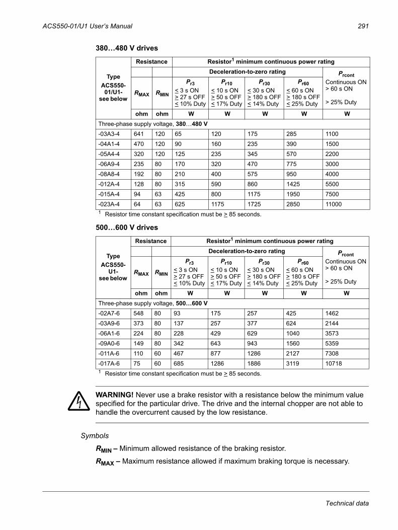
ACS550-01/U1 User’s Manual 291
380…480 V drives
500…600 V drives
WARNING! Never use a brake resistor with a resistance below the minimum value specified for the particular drive. The drive and the internal chopper are not able to handle the overcurrent caused by the low resistance.
Symbols
RMIN – Minimum allowed resistance of the braking resistor.
RMAX – Maximum resistance allowed if maximum braking torque is necessary.
TypeACS550-01/U1-
see below
Resistance Resistor1 minimum continuous power ratingDeceleration-to-zero rating Prcont
Continuous ON> 60 s ON
> 25% DutyRMAX RMIN
Pr3< 3 s ON> 27 s OFF< 10% Duty
Pr10< 10 s ON> 50 s OFF< 17% Duty
Pr30< 30 s ON> 180 s OFF< 14% Duty
Pr60< 60 s ON> 180 s OFF< 25% Duty
ohm ohm W W W W WThree-phase supply voltage, 380…480 V -03A3-4 641 120 65 120 175 285 1100
-04A1-4 470 120 90 160 235 390 1500
-05A4-4 320 120 125 235 345 570 2200
-06A9-4 235 80 170 320 470 775 3000
-08A8-4 192 80 210 400 575 950 4000
-012A-4 128 80 315 590 860 1425 5500
-015A-4 94 63 425 800 1175 1950 7500
-023A-4 64 63 625 1175 1725 2850 110001 Resistor time constant specification must be > 85 seconds.
TypeACS550-
U1-see below
Resistance Resistor1 minimum continuous power ratingDeceleration-to-zero rating Prcont
Continuous ON> 60 s ON
> 25% DutyRMAX RMIN
Pr3< 3 s ON> 27 s OFF< 10% Duty
Pr10< 10 s ON> 50 s OFF< 17% Duty
Pr30< 30 s ON> 180 s OFF< 14% Duty
Pr60< 60 s ON> 180 s OFF< 25% Duty
ohm ohm W W W W WThree-phase supply voltage, 500…600 V
-02A7-6 548 80 93 175 257 425 1462
-03A9-6 373 80 137 257 377 624 2144
-06A1-6 224 80 228 429 629 1040 3573
-09A0-6 149 80 342 643 943 1560 5359
-011A-6 110 60 467 877 1286 2127 7308
-017A-6 75 60 685 1286 1886 3119 107181 Resistor time constant specification must be > 85 seconds.
Technical data
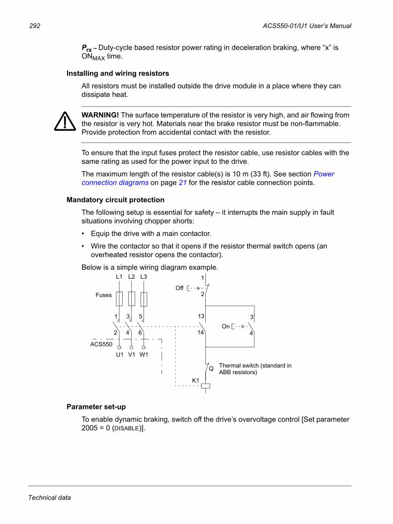
292 ACS550-01/U1 User’s Manual
Prx – Duty-cycle based resistor power rating in deceleration braking, where “x” is ONMAX time.
Installing and wiring resistorsAll resistors must be installed outside the drive module in a place where they can dissipate heat.
WARNING! The surface temperature of the resistor is very high, and air flowing from the resistor is very hot. Materials near the brake resistor must be non-flammable. Provide protection from accidental contact with the resistor.
To ensure that the input fuses protect the resistor cable, use resistor cables with the same rating as used for the power input to the drive.
The maximum length of the resistor cable(s) is 10 m (33 ft). See section Power connection diagrams on page 21 for the resistor cable connection points.
Mandatory circuit protectionThe following setup is essential for safety – it interrupts the main supply in fault situations involving chopper shorts:
• Equip the drive with a main contactor.
• Wire the contactor so that it opens if the resistor thermal switch opens (an overheated resistor opens the contactor).
Below is a simple wiring diagram example.
Parameter set-upTo enable dynamic braking, switch off the drive’s overvoltage control [Set parameter 2005 = 0 (DISABLE)].
ACS550
U1 V1 W1
L1 L2 L3
1
2
3
4
5
6
13
14
3
4
1
2
K1
Q Thermal switch (standard in ABB resistors)
On
OffFuses
Technical data
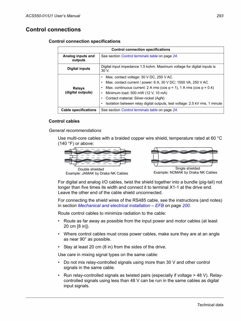
ACS550-01/U1 User’s Manual 293
Control connections
Control connection specifications
Control cables
General recommendations
Use multi-core cables with a braided copper wire shield, temperature rated at 60 °C (140 °F) or above:
For digital and analog I/O cables, twist the shield together into a bundle (pig-tail) not longer than five times its width and connect it to terminal X1-1 at the drive end. Leave the other end of the cable shield unconnected.
For connecting the shield wires of the RS485 cable, see the instructions (and notes) in section Mechanical and electrical installation – EFB on page 200.
Route control cables to minimize radiation to the cable:
• Route as far away as possible from the input power and motor cables (at least 20 cm [8 in]).
• Where control cables must cross power cables, make sure they are at an angle as near 90° as possible.
• Stay at least 20 cm (8 in) from the sides of the drive.
Use care in mixing signal types on the same cable:
• Do not mix relay-controlled signals using more than 30 V and other control signals in the same cable.
• Run relay-controlled signals as twisted pairs (especially if voltage > 48 V). Relay-controlled signals using less than 48 V can be run in the same cables as digital input signals.
Control connection specifications
Analog inputs and outputs
See section Control terminals table on page 24.
Digital inputs Digital input impedance 1.5 kohm. Maximum voltage for digital inputs is 30 V.
Relays(digital outputs)
• Max. contact voltage: 30 V DC, 250 V AC• Max. contact current / power: 6 A, 30 V DC; 1500 VA, 250 V AC• Max. continuous current: 2 A rms (cos ϕ = 1), 1 A rms (cos ϕ = 0.4)• Minimum load: 500 mW (12 V, 10 mA)• Contact material: Silver-nickel (AgN)• Isolation between relay digital outputs, test voltage: 2.5 kV rms, 1 minute
Cable specifications See section Control terminals table on page 24.
Double shielded Single shieldedExample: JAMAK by Draka NK Cables Example: NOMAK by Draka NK Cables
Technical data
294 ACS550-01/U1 User’s Manual
Note: Never mix 24 V DC and 115/230 V AC signals in the same cable.
Analog cables
Recommendations for analog signal runs:
• Use double shielded, twisted pair cable.
• Use one individually shielded pair for each signal.
• Do not use a common return for different analog signals.
Digital cables
Recommendation for digital signal runs: A double shielded cable is the best alternative, but single-shielded, twisted, multi-pair cable is also usable.
Control panel cable
If the control panel is connected to the drive with a cable, use only Category 5 Patch ethernet cable. The maximum length that is tested to meet EMC specifications is 3 m (9.8 ft). Longer cables are susceptible to electromagnetic noise and must be user- tested to verify that EMC requirements are met. Where long runs are required (especially for runs longer than about 12 m [40 ft]), use a RS232/RS485 converter at each end and run RS485 cable.
Drive’s control connection terminalsThe following table provides specifications for the drive’s control terminals
EfficiencyApproximately 98% at nominal power level.
Frame sizeControl
Maximum wire size 1 Tightening torque
mm2 AWG N·m lb·ft
All 1.5 16 0.4 0.31 Values given for solid wires.
For stranded wires, the maximum size is 1 mm2.
Technical data
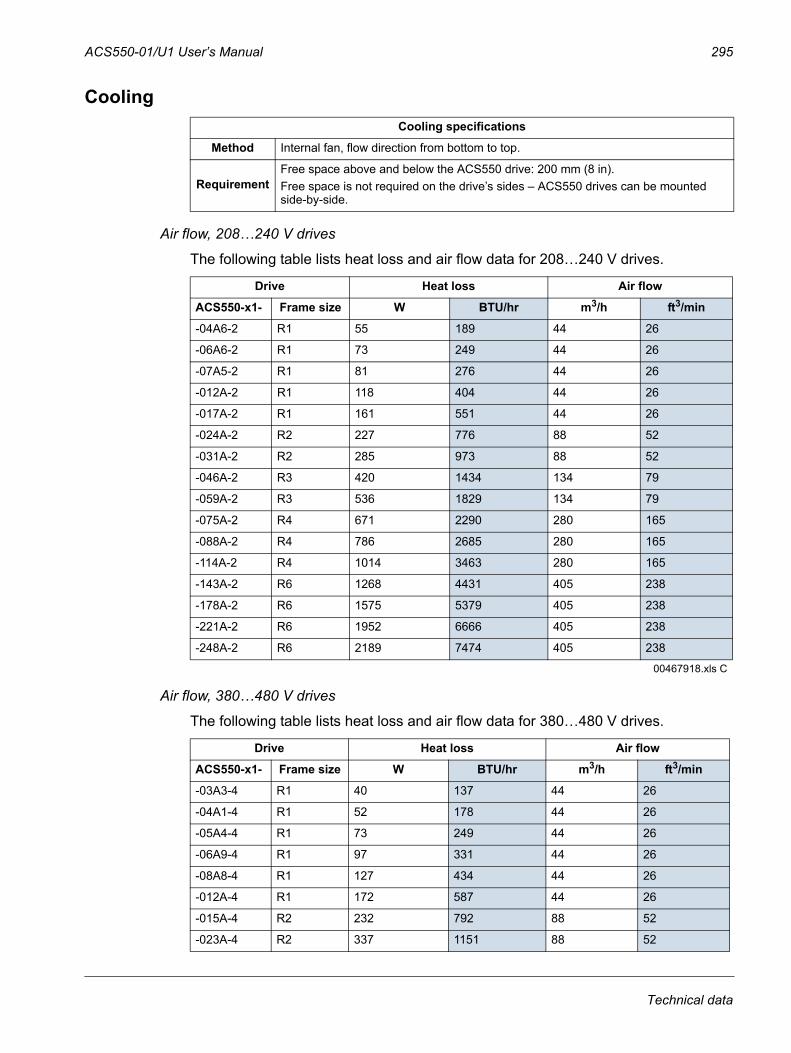
ACS550-01/U1 User’s Manual 295
Cooling
Air flow, 208…240 V drives
The following table lists heat loss and air flow data for 208…240 V drives.
Air flow, 380…480 V drives
The following table lists heat loss and air flow data for 380…480 V drives.
Cooling specifications
Method Internal fan, flow direction from bottom to top.
RequirementFree space above and below the ACS550 drive: 200 mm (8 in).Free space is not required on the drive’s sides – ACS550 drives can be mounted side-by-side.
Drive Heat loss Air flow
ACS550-x1- Frame size W BTU/hr m3/h ft3/min
-04A6-2 R1 55 189 44 26
-06A6-2 R1 73 249 44 26
-07A5-2 R1 81 276 44 26
-012A-2 R1 118 404 44 26
-017A-2 R1 161 551 44 26
-024A-2 R2 227 776 88 52
-031A-2 R2 285 973 88 52
-046A-2 R3 420 1434 134 79
-059A-2 R3 536 1829 134 79
-075A-2 R4 671 2290 280 165
-088A-2 R4 786 2685 280 165
-114A-2 R4 1014 3463 280 165
-143A-2 R6 1268 4431 405 238
-178A-2 R6 1575 5379 405 238
-221A-2 R6 1952 6666 405 238
-248A-2 R6 2189 7474 405 238
00467918.xls C
Drive Heat loss Air flow
ACS550-x1- Frame size W BTU/hr m3/h ft3/min
-03A3-4 R1 40 137 44 26
-04A1-4 R1 52 178 44 26
-05A4-4 R1 73 249 44 26
-06A9-4 R1 97 331 44 26
-08A8-4 R1 127 434 44 26
-012A-4 R1 172 587 44 26
-015A-4 R2 232 792 88 52
-023A-4 R2 337 1151 88 52
Technical data
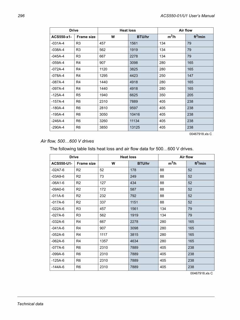
296 ACS550-01/U1 User’s Manual
Air flow, 500…600 V drives
The following table lists heat loss and air flow data for 500…600 V drives.
-031A-4 R3 457 1561 134 79
-038A-4 R3 562 1919 134 79
-045A-4 R3 667 2278 134 79
-059A-4 R4 907 3098 280 165
-072A-4 R4 1120 3825 280 165
-078A-4 R4 1295 4423 250 147
-087A-4 R4 1440 4918 280 165
-097A-4 R4 1440 4918 280 165
-125A-4 R5 1940 6625 350 205
-157A-4 R6 2310 7889 405 238
-180A-4 R6 2810 9597 405 238
-195A-4 R6 3050 10416 405 238
-246A-4 R6 3260 11134 405 238
-290A-4 R6 3850 13125 405 238
00467918.xls C
Drive Heat loss Air flow
ACS550-U1- Frame size W BTU/hr m3/h ft3/min
-02A7-6 R2 52 178 88 52
-03A9-6 R2 73 249 88 52
-06A1-6 R2 127 434 88 52
-09A0-6 R2 172 587 88 52
-011A-6 R2 232 792 88 52
-017A-6 R2 337 1151 88 52
-022A-6 R3 457 1561 134 79
-027A-6 R3 562 1919 134 79
-032A-6 R4 667 2278 280 165
-041A-6 R4 907 3098 280 165
-052A-6 R4 1117 3815 280 165
-062A-6 R4 1357 4634 280 165
-077A-6 R6 2310 7889 405 238
-099A-6 R6 2310 7889 405 238
-125A-6 R6 2310 7889 405 238
-144A-6 R6 2310 7889 405 238
00467918.xls C
Drive Heat loss Air flow
ACS550-x1- Frame size W BTU/hr m3/h ft3/min
Technical data
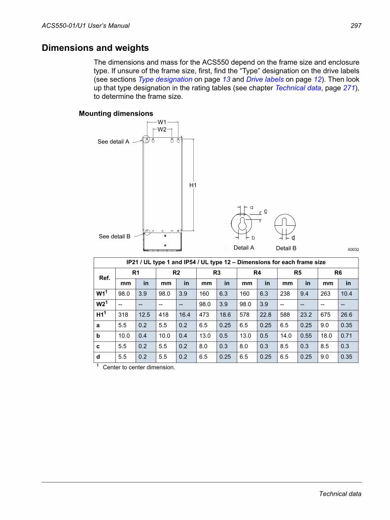
ACS550-01/U1 User’s Manual 297
Dimensions and weightsThe dimensions and mass for the ACS550 depend on the frame size and enclosure type. If unsure of the frame size, first, find the “Type” designation on the drive labels (see sections Type designation on page 13 and Drive labels on page 12). Then look up that type designation in the rating tables (see chapter Technical data, page 271), to determine the frame size.
Mounting dimensions
IP21 / UL type 1 and IP54 / UL type 12 – Dimensions for each frame size
Ref.R1 R2 R3 R4 R5 R6
mm in mm in mm in mm in mm in mm in
W11 98.0 3.9 98.0 3.9 160 6.3 160 6.3 238 9.4 263 10.4
W21 -- -- -- -- 98.0 3.9 98.0 3.9 -- -- -- --
H11 318 12.5 418 16.4 473 18.6 578 22.8 588 23.2 675 26.6
a 5.5 0.2 5.5 0.2 6.5 0.25 6.5 0.25 6.5 0.25 9.0 0.35
b 10.0 0.4 10.0 0.4 13.0 0.5 13.0 0.5 14.0 0.55 18.0 0.71
c 5.5 0.2 5.5 0.2 8.0 0.3 8.0 0.3 8.5 0.3 8.5 0.3
d 5.5 0.2 5.5 0.2 6.5 0.25 6.5 0.25 6.5 0.25 9.0 0.351 Center to center dimension.
X0032
b
H1
See detail A
a
W1
See detail B
W2
c
d
Detail BDetail A
Technical data
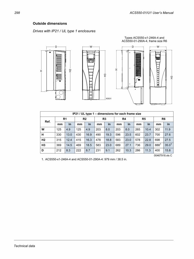
298 ACS550-01/U1 User’s Manual
Outside dimensions
Drives with IP21 / UL type 1 enclosures
IP21 / UL type 1 – dimensions for each frame size
Ref.R1 R2 R3 R4 R5 R6
mm in mm in mm in mm in mm in mm in
W 125 4.9 125 4.9 203 8.0 203 8.0 265 10.4 302 11.9
H 330 13.0 430 16.9 490 19.3 596 23.5 602 23.7 700 27.6
H2 315 12.4 415 16.3 478 18.8 583 23.0 578 22.8 698 27.5
H3 369 14.5 469 18.5 583 23.0 689 27.1 736 29.0 8881 35.01
D 212 8.3 222 8.7 231 9.1 262 10.3 286 11.3 400 15.8
00467918.xls C1. ACS550-x1-246A-4 and ACS550-01-290A-4: 979 mm / 38.5 in.
H H2
W
H3
D
X0031
D
H
Types ACS550-x1-246A-4 and ACS550-01-290A-4, frame size R6
W
H3
D W
H
H3
H2
Technical data
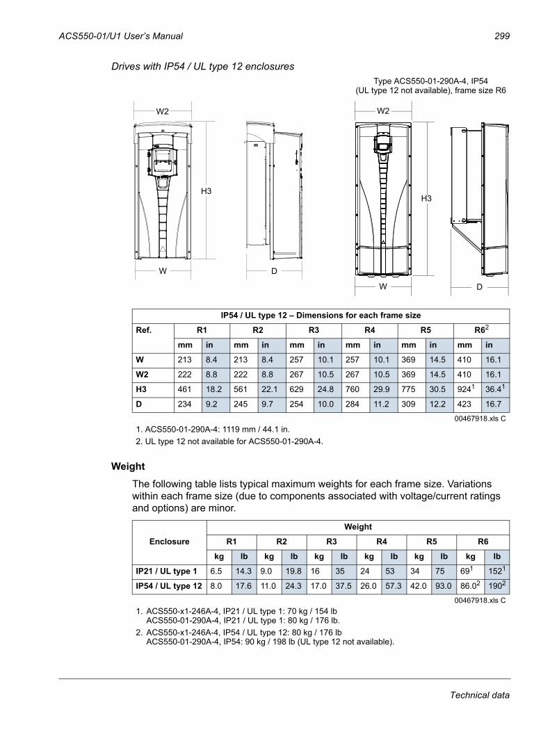
ACS550-01/U1 User’s Manual 299
Drives with IP54 / UL type 12 enclosures
WeightThe following table lists typical maximum weights for each frame size. Variations within each frame size (due to components associated with voltage/current ratings and options) are minor.
IP54 / UL type 12 – Dimensions for each frame size
Ref. R1 R2 R3 R4 R5 R62
mm in mm in mm in mm in mm in mm in
W 213 8.4 213 8.4 257 10.1 257 10.1 369 14.5 410 16.1
W2 222 8.8 222 8.8 267 10.5 267 10.5 369 14.5 410 16.1
H3 461 18.2 561 22.1 629 24.8 760 29.9 775 30.5 9241 36.41
D 234 9.2 245 9.7 254 10.0 284 11.2 309 12.2 423 16.7
00467918.xls C1. ACS550-01-290A-4: 1119 mm / 44.1 in.2. UL type 12 not available for ACS550-01-290A-4.
Enclosure
Weight
R1 R2 R3 R4 R5 R6
kg lb kg lb kg lb kg lb kg lb kg lb
IP21 / UL type 1 6.5 14.3 9.0 19.8 16 35 24 53 34 75 691 1521
IP54 / UL type 12 8.0 17.6 11.0 24.3 17.0 37.5 26.0 57.3 42.0 93.0 86.02 1902
00467918.xls C1. ACS550-x1-246A-4, IP21 / UL type 1: 70 kg / 154 lb
ACS550-01-290A-4, IP21 / UL type 1: 80 kg / 176 lb.2. ACS550-x1-246A-4, IP54 / UL type 12: 80 kg / 176 lb
ACS550-01-290A-4, IP54: 90 kg / 198 lb (UL type 12 not available).
H3
W D
W2
Type ACS550-01-290A-4, IP54 (UL type 12 not available), frame size R6
W2
H3
W D
Technical data

300 ACS550-01/U1 User’s Manual
Degrees of protectionAvailable enclosures:
• IP21 / UL type 1 enclosure. The site must be free of airborne dust, corrosive gases or liquids, and conductive contaminants such as condensation, carbon dust and metallic particles.
• IP54 / UL type 12 enclosure. This enclosure provides protection from airborne dust and light sprays or splashing water from all directions.
Note: UL type 12 enclosure is not available for type ACS550-01-290A-4.
Compared to the IP21 / UL type 1 enclosure, the IP54 / UL type 12 enclosure has:
• the same internal plastic shell as the IP21 enclosure
• a different outer plastic cover
• an additional internal fan to improve cooling
• larger dimensions
• the same rating (does not require a derating).
Ambient conditionsThe following table lists the ACS550 environmental requirements.
Ambient environment requirements
Installation site Storage and transportation in the protective package
Altitude
• 0…1000 m (0…3 300 ft)• 1000…2000 m (3 300…6 600 ft) if
PN and I2N derated 1% every 100 m above 1000 m (300 ft above 3 300 ft)
Ambient temperature
• Min. -15 °C (5 °F) – no frost allowed• Max. (fsw = 1 or 4) 40 °C (104 °F);
50 °C (122 °F) if PN and I2N derated to 90%
• Max. (fsw = 8) 40 °C (104 °F) if PN and I2N derated to 80%
• Max. (fsw = 12) 30 °C (86 °F) if PN and I2N derated to 65% (to 50% for 600 V, R4 frame sizes, that is for ACS550-U1-032A-6 … ACS550-U1-062A-6)
-40…70 °C (-40…158 °F)
Relative humidity
5…95%, no condensation allowed
Technical data
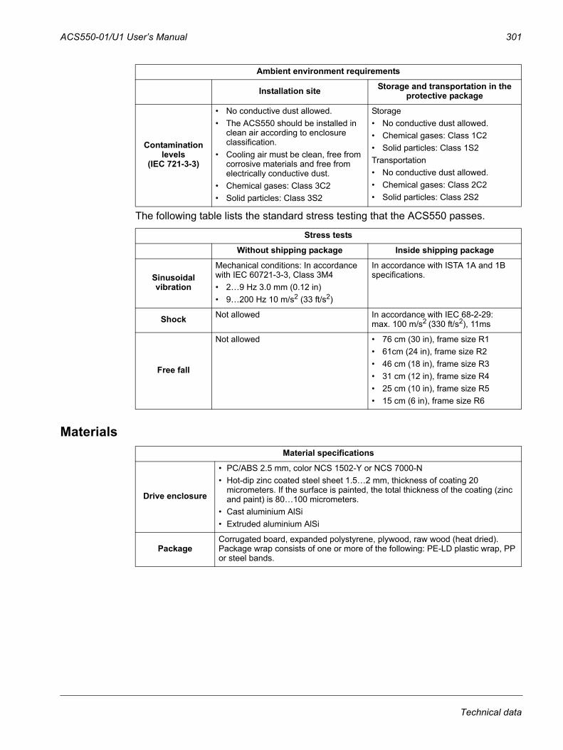
ACS550-01/U1 User’s Manual 301
The following table lists the standard stress testing that the ACS550 passes.
Materials
Contamination levels
(IEC 721-3-3)
• No conductive dust allowed.• The ACS550 should be installed in
clean air according to enclosure classification.
• Cooling air must be clean, free from corrosive materials and free from electrically conductive dust.
• Chemical gases: Class 3C2• Solid particles: Class 3S2
Storage• No conductive dust allowed.• Chemical gases: Class 1C2• Solid particles: Class 1S2Transportation• No conductive dust allowed.• Chemical gases: Class 2C2• Solid particles: Class 2S2
Stress tests
Without shipping package Inside shipping package
Sinusoidal vibration
Mechanical conditions: In accordance with IEC 60721-3-3, Class 3M4• 2…9 Hz 3.0 mm (0.12 in)• 9…200 Hz 10 m/s2 (33 ft/s2)
In accordance with ISTA 1A and 1B specifications.
Shock Not allowed In accordance with IEC 68-2-29:max. 100 m/s2 (330 ft/s2), 11ms
Free fall
Not allowed • 76 cm (30 in), frame size R1• 61cm (24 in), frame size R2• 46 cm (18 in), frame size R3• 31 cm (12 in), frame size R4• 25 cm (10 in), frame size R5• 15 cm (6 in), frame size R6
Material specifications
Drive enclosure
• PC/ABS 2.5 mm, color NCS 1502-Y or NCS 7000-N• Hot-dip zinc coated steel sheet 1.5…2 mm, thickness of coating 20
micrometers. If the surface is painted, the total thickness of the coating (zinc and paint) is 80…100 micrometers.
• Cast aluminium AlSi • Extruded aluminium AlSi
PackageCorrugated board, expanded polystyrene, plywood, raw wood (heat dried). Package wrap consists of one or more of the following: PE-LD plastic wrap, PP or steel bands.
Ambient environment requirements
Installation site Storage and transportation in the protective package
Technical data
302 ACS550-01/U1 User’s Manual
Disposal
The drive contains raw materials that should be recycled to preserve energy and natural resources. The package materials are environmentally compatible and recyclable. All metal parts can be recycled. The plastic parts can either be recycled or burned under controlled circumstances, according to local regulations. Most recyclable parts are marked with recycling marks.If recycling is not feasible, all parts excluding electrolytic capacitors and printed circuit boards can be landfilled. The DC capacitors contain electrolyte and, if the drive is not provided with the RoHS marking, the printed circuit boards contain lead, both of which are classified as hazardous waste within the EU. They must be removed and handled according to local regulations. For further information on environmental aspects and more detailed recycling instructions, please contact your local ABB distributor.
Material specifications
Technical data
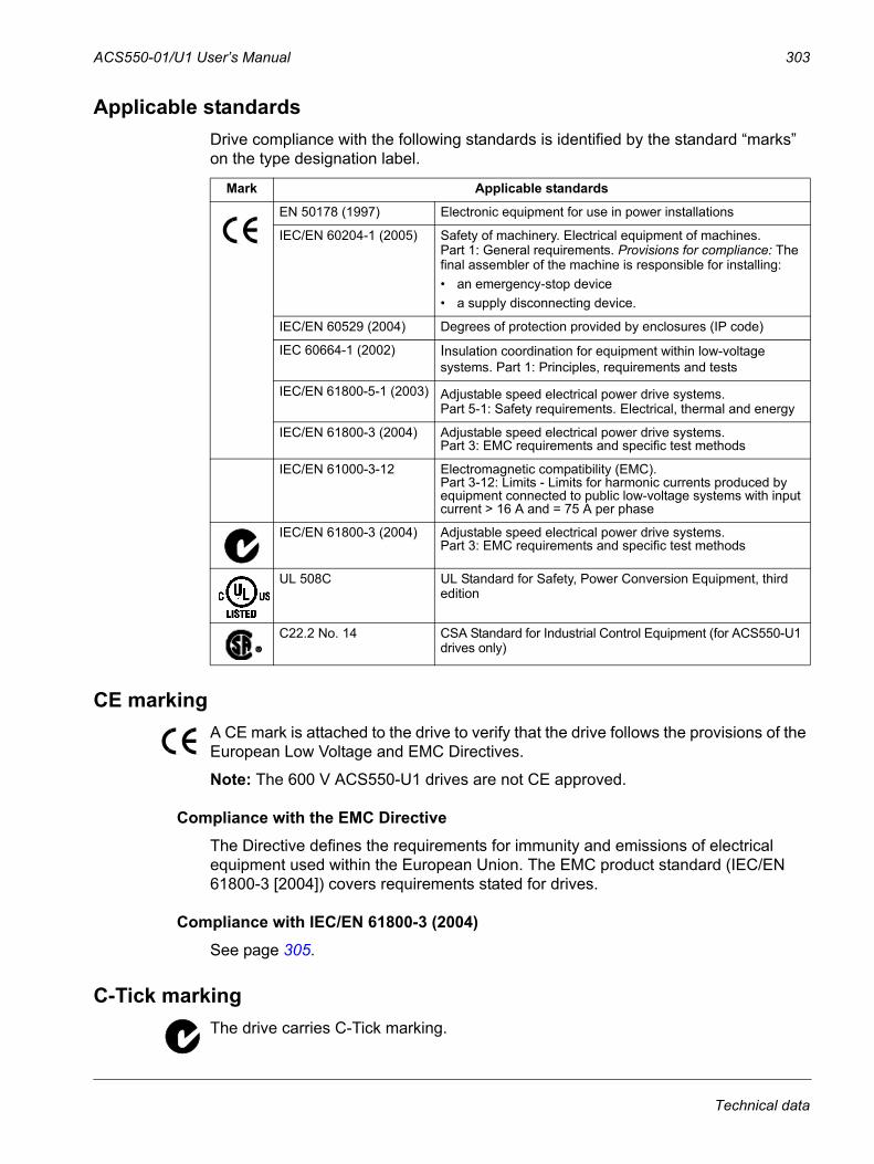
ACS550-01/U1 User’s Manual 303
Applicable standardsDrive compliance with the following standards is identified by the standard “marks” on the type designation label.
CE markingA CE mark is attached to the drive to verify that the drive follows the provisions of the European Low Voltage and EMC Directives.
Note: The 600 V ACS550-U1 drives are not CE approved.
Compliance with the EMC DirectiveThe Directive defines the requirements for immunity and emissions of electrical equipment used within the European Union. The EMC product standard (IEC/EN 61800-3 [2004]) covers requirements stated for drives.
Compliance with IEC/EN 61800-3 (2004)See page 305.
C-Tick markingThe drive carries C-Tick marking.
Mark Applicable standards
EN 50178 (1997) Electronic equipment for use in power installations
IEC/EN 60204-1 (2005) Safety of machinery. Electrical equipment of machines.Part 1: General requirements. Provisions for compliance: The final assembler of the machine is responsible for installing:• an emergency-stop device • a supply disconnecting device.
IEC/EN 60529 (2004) Degrees of protection provided by enclosures (IP code)
IEC 60664-1 (2002) Insulation coordination for equipment within low-voltage systems. Part 1: Principles, requirements and tests
IEC/EN 61800-5-1 (2003) Adjustable speed electrical power drive systems.Part 5-1: Safety requirements. Electrical, thermal and energy
IEC/EN 61800-3 (2004) Adjustable speed electrical power drive systems.Part 3: EMC requirements and specific test methods
IEC/EN 61000-3-12 Electromagnetic compatibility (EMC).Part 3-12: Limits - Limits for harmonic currents produced by equipment connected to public low-voltage systems with input current > 16 A and = 75 A per phase
IEC/EN 61800-3 (2004) Adjustable speed electrical power drive systems.Part 3: EMC requirements and specific test methods
UL 508C UL Standard for Safety, Power Conversion Equipment, third edition
C22.2 No. 14 CSA Standard for Industrial Control Equipment (for ACS550-U1 drives only)
Technical data
304 ACS550-01/U1 User’s Manual
C-Tick marking is required in Australia and New Zealand. A C-Tick mark is attached to the drive to verify compliance with the relevant standard (IEC 61800-3 (2004) – Adjustable speed electrical power drive systems – Part 3: EMC product standard including specific test methods), mandated by the Trans-Tasman Electromagnetic Compatibility Scheme.
The Trans-Tasman Electromagnetic Compatibility Scheme (EMCS) was introduced by the Australian Communication Authority (ACA) and the Radio Spectrum Management Group (RSM) of the New Zealand Ministry of Economic Development (NZMED) in November 2001. The aim of the scheme is to protect the radio frequency spectrum by introducing technical limits for emission from electrical/electronic products.
Compliance with IEC/EN 61800-3 (2004)See page 305.
UL/CSA markingsAn UL mark is attached to ACS550 drives to verify that the drive follows the provisions of UL 508C.
A CSA mark is attached to ACS550-U1 type drives to verify that the drive follows the provisions of C22.2 NO. 14.
The ACS550 is suitable for use in a circuit capable of delivering not more than 100 kA RMS symmetrical amperes, 600 V maximum. The ampere rating is based on tests done according to UL 508.
Branch circuit protection must be provided in accordance with local codes.
The ACS550 has an electronic motor protection feature that complies with the requirements of UL 508C and, for ACS550-U1, C22.2 No. 14. When this feature is selected and properly adjusted, additional overload protection is not required unless more than one motor is connected to the drive or unless additional protection is required by applicable safety regulations. See parameters 3005 (MOT THERM PROT) and 3006 (MOT THERM RATE).
The drives are to be used in a controlled environment. See section Ambient conditions on page 300 for specific limits.
Note: For open type enclosures, i.e. drives without the conduit box and/or cover for IP21 / UL type 1 drives, or without the conduit plate and/or hood for IP54 / UL type 12 drives, the drive must be mounted inside an enclosure in accordance with National Electric Code and local electrical codes.
Brake choppers, when applied with appropriately sized brake resistors, will allow the drive to dissipate regenerative energy (normally associated with quickly decelerating a motor). Frame sizes R1 and R2 have a built-in brake chopper as standard equipment. For frame sizes R3…R6, contact your ABB representative for appropriate parts. See section Brake components on page 289.
Technical data
ACS550-01/U1 User’s Manual 305
IEC/EN 61800-3 (2004) DefinitionsEMC stands for Electromagnetic Compatibility. It is the ability of electrical/electronic equipment to operate without problems within an electromagnetic environment. Likewise, the equipment must not disturb or interfere with any other product or system within its locality.
First environment includes establishments connected to a low-voltage network which supplies buildings used for domestic purposes.
Second environment includes establishments connected to a network not directly supplying domestic premises.
Drive of category C2: drive of rated voltage less than 1000 V and intended to be installed and commissioned only by a professional when used in the first environment.
Note: A professional is a person or organisation having necessary skills in installing and/or commissioning power drive systems, including their EMC aspects.
Category C2 has the same EMC emission limits as the earlier class first environment restricted distribution. EMC standard IEC/EN 61800-3 does not any more restrict the distribution of the drive, but the using, installation and commissioning are defined.
Drive of category C3: drive of rated voltage less than 1000 V, intended for use in the second environment and not intended for use in the first environment.
Category C3 has the same EMC emission limits as the earlier class second environment unrestricted distribution.
Compliance with the IEC/EN 61800-3 (2004)The immunity performance of the drive complies with the demands of IEC/EN 61800-3, category C2 (see page 305 for IEC/EN 61800-3 definitions). The emission limits of IEC/EN 61800-3 are complied with the provisions described below.
First environment (drives of category C2)1. The internal EMC filter is connected.
2. The motor and control cables are selected as specified in this manual.
3. The drive is installed according to the instructions given in this manual.
4. The motor cable length does not exceed the allowed maximum length specified in section Motor cable length for 400 V drives on page 284 for the frame size and switching frequency in use.
WARNING! In a domestic environment, this product may cause radio inference, in which case supplementary mitigation measures may be required.
Second environment (drives of category C3)1. The internal EMC filter is connected.
2. The motor and control cables are selected as specified in this manual.
3. The drive is installed according to the instructions given in this manual.
Technical data
306 ACS550-01/U1 User’s Manual
4. The motor cable length does not exceed the allowed maximum length specified in section Motor cable length for 400 V drives on page 284 for the frame size and switching frequency in use.
WARNING! A drive of category C3 is not intended to be used on a low-voltage public network which supplies domestic premises. Radio frequency interference is expected if the drive is used on such a network.
Note: It is not allowed to install a drive with the internal EMC filter connected on IT (ungrounded) systems. The supply network becomes connected to ground potential through the EMC filter capacitors, which may cause danger or damage the drive.
Note: It is not allowed to install a drive with the internal EMC filter connected to a corner grounded TN system as this would damage the drive.
Product protection in the USAThis product is protected by one or more of the following US patents:
4,920,306 5,301,085 5,463,302 5,521,483 5,532,568 5,589,754 5,612,604 5,654,624 5,799,805 5,940,286 5,942,874 5,952,6136,094,364 6,147,887 6,175,256 6,184,740 6,195,274 6,229,3566,252,436 6,265,724 6,305,464 6,313,599 6,316,896 6,335,6076,370,049 6,396,236 6,448,735 6,498,452 6,552,510 6,597,1486,600,290 6,741,059 6,774,758 6,844,794 6,856,502 6,859,3746,922,883 6,940,253 6,934,169 6,956,352 6,958,923 6,967,4536,972,976 6,977,449 6,984,958 6,985,371 6,992,908 6,999,3297,023,160 7,034,510 7,036,223 7,045,987 7,057,908 7,059,3907,067,997 7,082,374 7,084,604 7,098,623 7,102,325 7,109,7807,164,562 7,176,779 7,190,599 7,215,099 7,221,152 7,227,3257,245,197 7,250,739 7,262,577 7,271,505 7,274,573 7,279,8027,280,938 7,330,095 7,349,814 7,352,220 7,365,622 7,372,6967,388,765 D503,931 D510,319 D510,320 D511,137 D511,150D512,026 D512,696 D521,466 D541,743S D541,744S D541,745SD548,182S D548,183S
Other patents pending.
Technical data
ACS550-01/U1 User’s Manual 307
Index
Numerics0xxxx register
EFB function codes . . . . . . . . . . . . . . . . . . . 214EFB mapping . . . . . . . . . . . . . . . . . . . . . . . 212
1xxxx registerEFB function codes . . . . . . . . . . . . . . . . . . . 215EFB mapping . . . . . . . . . . . . . . . . . . . . . . . 214
2-wire sensor/transmitter, connection example . . 823-wire macro . . . . . . . . . . . . . . . . . . . . . . . . . . . . 753-wire sensor/transmitter, connection example . . 823xxxx register
EFB function codes . . . . . . . . . . . . . . . . . . . 215EFB mapping . . . . . . . . . . . . . . . . . . . . . . . 215
4xxxx registerEFB function codes . . . . . . . . . . . . . . . . . . . 217EFB mapping . . . . . . . . . . . . . . . . . . . . . . . 215
AABB
document library . . . . . . . . . . . . . . . . . . . . . 319feedback on ABB manuals . . . . . . . . . . . . . 319product and service inquiries . . . . . . . . . . . 319product training . . . . . . . . . . . . . . . . . . . . . . 319standard (default) macro . . . . . . . . . . . . . . . . 74
acceleration/deceleration, parameter group. . . . . . . . . . 135at aux. stop (PFC), parameter. . . . . . . . . . . 197compensation, parameter . . . . . . . . . . . . . . 138ramp select, parameter . . . . . . . . . . . . . . . . 135ramp shape, parameter. . . . . . . . . . . . . . . . 135ramp time (PFC), parameter . . . . . . . . . . . . 197ramp zero select, parameter . . . . . . . . . . . . 136time, parameter . . . . . . . . . . . . . . . . . . . . . . 135
activate (external PID), parameter. . . . . . . . . . . 174actual input (PID), parameters. . . . . . . . . . . . . . 170actual max. (PID), parameters. . . . . . . . . . . . . . 170actual min. (PID), parameters . . . . . . . . . . . . . . 170actual values
mapping, FBA, generic profile. . . . . . . . . . . 251scaling, EFB comm . . . . . . . . . . . . . . . . . . . 207scaling, FBA comm . . . . . . . . . . . . . . . . . . . 238scaling, FBA, ABB drives profile . . . . . . . . . 249scaling, FBA, generic profile . . . . . . . . . . . . 251
alarmcodes. . . . . . . . . . . . . . . . . . . . . . . . . . . . . . 261codes (Basic Control Panel) . . . . . . . . . . . . 263display enable, parameter. . . . . . . . . . . . . . 128listing . . . . . . . . . . . . . . . . . . . . . . . . . . . . . . 261words, data parameters . . . . . . . . . . . . . . . 109
alternate macro . . . . . . . . . . . . . . . . . . . . . . . . . . 76altitude
derating . . . . . . . . . . . . . . . . . . . . . . . . . . . . 274environment limit . . . . . . . . . . . . . . . . . . . . . 300shipping limit . . . . . . . . . . . . . . . . . . . . . . . . 300
ambient conditions. . . . . . . . . . . . . . . . . . . . . . . 300
ambient temperaturederating . . . . . . . . . . . . . . . . . . . . . . . . . . . . 274environment limit . . . . . . . . . . . . . . . . . . . . . 300shipping limit. . . . . . . . . . . . . . . . . . . . . . . . . 300
amplitude loggingsee load analyzer
analog cable, requirements. . . . . . . . . . . . . . . . . 294analog I/O
connections . . . . . . . . . . . . . . . . . . . . . . . . . . 24specifications . . . . . . . . . . . . . . . . . . . . . . . . . 24
analog inputparameter group. . . . . . . . . . . . . . . . . . . . . . 119data parameter . . . . . . . . . . . . . . . . . . . . . . . 105fault limit, parameters . . . . . . . . . . . . . . . . . . 146filter, parameters . . . . . . . . . . . . . . . . . . . . . 119less than min. auto. reset, parameter. . . . . . 148less than min., fault parameter . . . . . . . . . . . 144loss, fault codes . . . . . . . . . . . . . . . . . . . . . . 255maximum, parameters . . . . . . . . . . . . . . . . . 119minimum, parameters. . . . . . . . . . . . . . . . . . 119
analog outputparameter group. . . . . . . . . . . . . . . . . . . . . . 123content max., parameters. . . . . . . . . . . . . . . 123content min., parameters . . . . . . . . . . . . . . . 123current max., parameters . . . . . . . . . . . . . . . 123current min., parameters . . . . . . . . . . . . . . . 123data content, parameters . . . . . . . . . . . . . . . 123data parameters . . . . . . . . . . . . . . . . . . . . . . 105filter, parameters . . . . . . . . . . . . . . . . . . . . . 123
analyzer, loadsee load analyzer
anglemechanical, data parameter. . . . . . . . . . . . . 106
application block output, data parameter . . . . . . 104application macro, parameter . . . . . . . . . . . . . . . 102application macros
see macrosarrow (Assistant Control Panel) . . . . . . . . . . . . . . 45assistant (Assistant Control Panel)
start-up . . . . . . . . . . . . . . . . . . . . . . . . . . . . . . 53tasks . . . . . . . . . . . . . . . . . . . . . . . . . . . . . . . . 54
Assistant Control Panelsee control panel (Assistant)
assistants mode (Assistant Control Panel) . . . . . . 53autochange
interval, parameter . . . . . . . . . . . . . . . . . . . . 190level, parameter . . . . . . . . . . . . . . . . . . . . . . 191overview . . . . . . . . . . . . . . . . . . . . . . . . . . . . 191starting order counter . . . . . . . . . . . . . . . . . . 191
automatic resetsee reset, automatic
auxiliary motorsee motor, auxiliary
Index
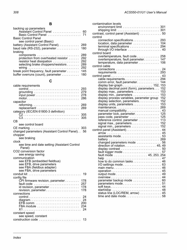
308 ACS550-01/U1 User’s Manual
Bbacking up parameters
Assistant Control Panel . . . . . . . . . . . . . . . . 60Basic Control Panel . . . . . . . . . . . . . . . . . . . 71
Basic Control Panelsee control panel (Basic)
battery (Assistant Control Panel). . . . . . . . . . . . 269baud rate (RS-232), parameter . . . . . . . . . . . . . 180braking
components . . . . . . . . . . . . . . . . . . . . . . . . 289protection from overheated resistor . . . . . . 292resistor heat dissipation . . . . . . . . . . . . . . . 292selecting brake choppers/resistors . . . . . . . 289wiring . . . . . . . . . . . . . . . . . . . . . . . . . . . . . 292
break point frequency, fault parameter . . . . . . . 145buffer overruns (count), parameter . . . . . . . . . . 180
Ccable requirements
control . . . . . . . . . . . . . . . . . . . . . . . . . . . . . 293grounding . . . . . . . . . . . . . . . . . . . . . . . . . . 279input power . . . . . . . . . . . . . . . . . . . . . . . . . 278motor. . . . . . . . . . . . . . . . . . . . . . . . . . . . . . 286
capacitorreforming. . . . . . . . . . . . . . . . . . . . . . . . . . . 269replacement . . . . . . . . . . . . . . . . . . . . . . . . 269
category (IEC/EN 61800-3 definition)C2 . . . . . . . . . . . . . . . . . . . . . . . . . . . . . . . . 305C3 . . . . . . . . . . . . . . . . . . . . . . . . . . . . . . . . 305
CBsee control board
CE marking . . . . . . . . . . . . . . . . . . . . . . . . . . . . 303changed parameters (Assistant Control Panel). . 56chopper
see brakingclock
see time and date setting (Assistant Control Panel)
CO2 conversion factorsee energy saving
communicationsee EFB (embedded fieldbus)see EFB, drive parameterssee FBA (fieldbus adapter)see FBA, drive parameters
conduit kit . . . . . . . . . . . . . . . . . . . . . . . . . . . . . . 19config file
CPI firmware revision, parameter . . . . . . . . 178fault code . . . . . . . . . . . . . . . . . . . . . . . . . . 257id revision, parameter . . . . . . . . . . . . . . . . . 178revision, parameter . . . . . . . . . . . . . . . . . . . 178
connectionscontrol . . . . . . . . . . . . . . . . . . . . . . . . . . . . . . 24diagram. . . . . . . . . . . . . . . . . . . . . . . . . . . . . 24EFB comm . . . . . . . . . . . . . . . . . . . . . . . . . 200FBA module . . . . . . . . . . . . . . . . . . . . . . . . 234X1 . . . . . . . . . . . . . . . . . . . . . . . . . . . . . . . . . 24
constant speedsee speed, constant
construction code . . . . . . . . . . . . . . . . . . . . . . . . 13
contamination levelsenvironment limit . . . . . . . . . . . . . . . . . . . . . 301shipping limit . . . . . . . . . . . . . . . . . . . . . . . . 301
contrast, control panel (Assistant) . . . . . . . . . . . . 50control
connection specifications . . . . . . . . . . . . . . . 293location, data parameter . . . . . . . . . . . . . . . 104terminal specifications . . . . . . . . . . . . . . . . . 294through I/O interface . . . . . . . . . . . . . . . . . . . 40
control boardovertemperature, fault code . . . . . . . . . . . . . 258overtemperature, fault parameter. . . . . . . . . 147temperature, data parameter . . . . . . . . . . . . 106
control cableconnections . . . . . . . . . . . . . . . . . . . . . . . . . . 24requirements . . . . . . . . . . . . . . . . . . . . . . . . 293
control panel . . . . . . . . . . . . . . . . . . . . . . . . . . . . . 43cable requirements. . . . . . . . . . . . . . . . . . . . 294comm error, fault parameter. . . . . . . . . . . . . 144display bar-graph . . . . . . . . . . . . . . . . . 152, 153display decimal point (form), parameters . . . 152display max., parameters . . . . . . . . . . . . . . . 153display min., parameters . . . . . . . . . . . . . . . 153display process variables, parameter group 152display selection, parameters. . . . . . . . . . . . 152display units, parameters . . . . . . . . . . . . . . . 153maintenance. . . . . . . . . . . . . . . . . . . . . . . . . 269manual compatibility. . . . . . . . . . . . . . . . . . . . 43parameter lock, parameter . . . . . . . . . . . . . . 125pass code, parameter . . . . . . . . . . . . . . . . . 125reference control, parameter . . . . . . . . . . . . 113signal max., parameters. . . . . . . . . . . . . . . . 152signal min., parameters . . . . . . . . . . . . . . . . 152
control panel (Assistant) . . . . . . . . . . . . . . . . . . . . 44arrow . . . . . . . . . . . . . . . . . . . . . . . . . . . . . . . 45assistants mode . . . . . . . . . . . . . . . . . . . . . . . 53battery . . . . . . . . . . . . . . . . . . . . . . . . . . . . . 269changed parameters mode . . . . . . . . . . . . . . 56direction of rotation. . . . . . . . . . . . . . . . . . 45, 49display contrast . . . . . . . . . . . . . . . . . . . . . . . 50fault logger mode . . . . . . . . . . . . . . . . . . . . . . 57fault mode . . . . . . . . . . . . . . . . . . . 45, 253, 254help . . . . . . . . . . . . . . . . . . . . . . . . . . . . . . . . 47how to do common tasks . . . . . . . . . . . . . . . . 46I/O settings mode . . . . . . . . . . . . . . . . . . . . . . 63main menu . . . . . . . . . . . . . . . . . . . . . . . . . . . 46operation . . . . . . . . . . . . . . . . . . . . . . . . . . . . 45output mode . . . . . . . . . . . . . . . . . . . . . . . . . . 49overview . . . . . . . . . . . . . . . . . . . . . . . . . . . . . 44parameter backup mode . . . . . . . . . . . . . . . . 60parameters mode . . . . . . . . . . . . . . . . . . . . . . 51soft keys . . . . . . . . . . . . . . . . . . . . . . . . . . . . . 44start/stop . . . . . . . . . . . . . . . . . . . . . . . . . . . . 48status line (LOC/REM, arrow) . . . . . . . . . . . . 45time and date mode . . . . . . . . . . . . . . . . . . . . 58
Index
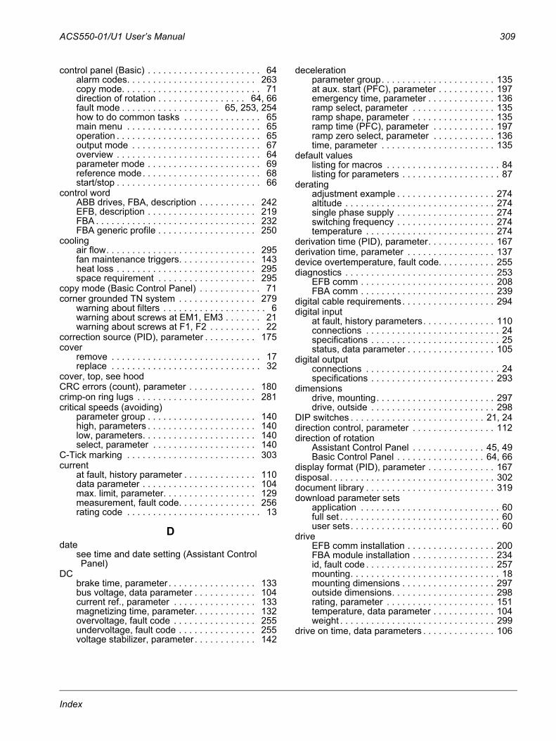
ACS550-01/U1 User’s Manual 309
control panel (Basic) . . . . . . . . . . . . . . . . . . . . . . 64alarm codes. . . . . . . . . . . . . . . . . . . . . . . . . 263copy mode. . . . . . . . . . . . . . . . . . . . . . . . . . . 71direction of rotation . . . . . . . . . . . . . . . . . 64, 66fault mode . . . . . . . . . . . . . . . . . . . 65, 253, 254how to do common tasks . . . . . . . . . . . . . . . 65main menu . . . . . . . . . . . . . . . . . . . . . . . . . . 65operation . . . . . . . . . . . . . . . . . . . . . . . . . . . . 65output mode . . . . . . . . . . . . . . . . . . . . . . . . . 67overview . . . . . . . . . . . . . . . . . . . . . . . . . . . . 64parameter mode . . . . . . . . . . . . . . . . . . . . . . 69reference mode. . . . . . . . . . . . . . . . . . . . . . . 68start/stop . . . . . . . . . . . . . . . . . . . . . . . . . . . . 66
control wordABB drives, FBA, description . . . . . . . . . . . 242EFB, description . . . . . . . . . . . . . . . . . . . . . 219FBA . . . . . . . . . . . . . . . . . . . . . . . . . . . . . . . 232FBA generic profile . . . . . . . . . . . . . . . . . . . 250
coolingair flow. . . . . . . . . . . . . . . . . . . . . . . . . . . . . 295fan maintenance triggers. . . . . . . . . . . . . . . 143heat loss . . . . . . . . . . . . . . . . . . . . . . . . . . . 295space requirement . . . . . . . . . . . . . . . . . . . 295
copy mode (Basic Control Panel) . . . . . . . . . . . . 71corner grounded TN system . . . . . . . . . . . . . . . 279
warning about filters . . . . . . . . . . . . . . . . . . . . 6warning about screws at EM1, EM3 . . . . . . . 21warning about screws at F1, F2 . . . . . . . . . . 22
correction source (PID), parameter . . . . . . . . . . 175cover
remove . . . . . . . . . . . . . . . . . . . . . . . . . . . . . 17replace . . . . . . . . . . . . . . . . . . . . . . . . . . . . . 32
cover, top, see hoodCRC errors (count), parameter . . . . . . . . . . . . . 180crimp-on ring lugs . . . . . . . . . . . . . . . . . . . . . . . 281critical speeds (avoiding)
parameter group . . . . . . . . . . . . . . . . . . . . . 140high, parameters . . . . . . . . . . . . . . . . . . . . . 140low, parameters. . . . . . . . . . . . . . . . . . . . . . 140select, parameter . . . . . . . . . . . . . . . . . . . . 140
C-Tick marking . . . . . . . . . . . . . . . . . . . . . . . . . 303current
at fault, history parameter . . . . . . . . . . . . . . 110data parameter . . . . . . . . . . . . . . . . . . . . . . 104max. limit, parameter. . . . . . . . . . . . . . . . . . 129measurement, fault code. . . . . . . . . . . . . . . 256rating code . . . . . . . . . . . . . . . . . . . . . . . . . . 13
Ddate
see time and date setting (Assistant Control Panel)
DCbrake time, parameter . . . . . . . . . . . . . . . . . 133bus voltage, data parameter . . . . . . . . . . . . 104current ref., parameter . . . . . . . . . . . . . . . . 133magnetizing time, parameter. . . . . . . . . . . . 132overvoltage, fault code . . . . . . . . . . . . . . . . 255undervoltage, fault code . . . . . . . . . . . . . . . 255voltage stabilizer, parameter . . . . . . . . . . . . 142
decelerationparameter group. . . . . . . . . . . . . . . . . . . . . . 135at aux. start (PFC), parameter . . . . . . . . . . . 197emergency time, parameter . . . . . . . . . . . . . 136ramp select, parameter . . . . . . . . . . . . . . . . 135ramp shape, parameter . . . . . . . . . . . . . . . . 135ramp time (PFC), parameter . . . . . . . . . . . . 197ramp zero select, parameter . . . . . . . . . . . . 136time, parameter . . . . . . . . . . . . . . . . . . . . . . 135
default valueslisting for macros . . . . . . . . . . . . . . . . . . . . . . 84listing for parameters . . . . . . . . . . . . . . . . . . . 87
deratingadjustment example . . . . . . . . . . . . . . . . . . . 274altitude . . . . . . . . . . . . . . . . . . . . . . . . . . . . . 274single phase supply . . . . . . . . . . . . . . . . . . . 274switching frequency . . . . . . . . . . . . . . . . . . . 274temperature . . . . . . . . . . . . . . . . . . . . . . . . . 274
derivation time (PID), parameter. . . . . . . . . . . . . 167derivation time, parameter . . . . . . . . . . . . . . . . . 137device overtemperature, fault code. . . . . . . . . . . 255diagnostics . . . . . . . . . . . . . . . . . . . . . . . . . . . . . 253
EFB comm . . . . . . . . . . . . . . . . . . . . . . . . . . 208FBA comm . . . . . . . . . . . . . . . . . . . . . . . . . . 239
digital cable requirements . . . . . . . . . . . . . . . . . . 294digital input
at fault, history parameters. . . . . . . . . . . . . . 110connections . . . . . . . . . . . . . . . . . . . . . . . . . . 24specifications . . . . . . . . . . . . . . . . . . . . . . . . . 25status, data parameter . . . . . . . . . . . . . . . . . 105
digital outputconnections . . . . . . . . . . . . . . . . . . . . . . . . . . 24specifications . . . . . . . . . . . . . . . . . . . . . . . . 293
dimensionsdrive, mounting. . . . . . . . . . . . . . . . . . . . . . . 297drive, outside . . . . . . . . . . . . . . . . . . . . . . . . 298
DIP switches . . . . . . . . . . . . . . . . . . . . . . . . . . 21, 24direction control, parameter . . . . . . . . . . . . . . . . 112direction of rotation
Assistant Control Panel . . . . . . . . . . . . . . 45, 49Basic Control Panel . . . . . . . . . . . . . . . . . 64, 66
display format (PID), parameter . . . . . . . . . . . . . 167disposal. . . . . . . . . . . . . . . . . . . . . . . . . . . . . . . . 302document library . . . . . . . . . . . . . . . . . . . . . . . . . 319download parameter sets
application . . . . . . . . . . . . . . . . . . . . . . . . . . . 60full set . . . . . . . . . . . . . . . . . . . . . . . . . . . . . . . 60user sets. . . . . . . . . . . . . . . . . . . . . . . . . . . . . 60
driveEFB comm installation . . . . . . . . . . . . . . . . . 200FBA module installation . . . . . . . . . . . . . . . . 234id, fault code . . . . . . . . . . . . . . . . . . . . . . . . . 257mounting. . . . . . . . . . . . . . . . . . . . . . . . . . . . . 18mounting dimensions . . . . . . . . . . . . . . . . . . 297outside dimensions. . . . . . . . . . . . . . . . . . . . 298rating, parameter . . . . . . . . . . . . . . . . . . . . . 151temperature, data parameter . . . . . . . . . . . . 104weight . . . . . . . . . . . . . . . . . . . . . . . . . . . . . . 299
drive on time, data parameters . . . . . . . . . . . . . . 106
Index
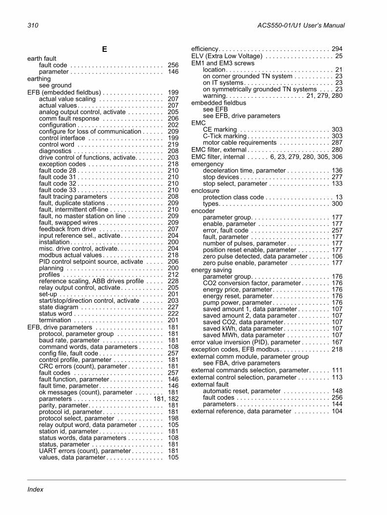
310 ACS550-01/U1 User’s Manual
Eearth fault
fault code . . . . . . . . . . . . . . . . . . . . . . . . . . 256parameter . . . . . . . . . . . . . . . . . . . . . . . . . . 146
earthingsee ground
EFB (embedded fieldbus) . . . . . . . . . . . . . . . . . 199actual value scaling . . . . . . . . . . . . . . . . . . 207actual values. . . . . . . . . . . . . . . . . . . . . . . . 207analog output control, activate . . . . . . . . . . 205comm fault response . . . . . . . . . . . . . . . . . 206configuration . . . . . . . . . . . . . . . . . . . . . . . . 202configure for loss of communication . . . . . . 209control interface . . . . . . . . . . . . . . . . . . . . . 199control word . . . . . . . . . . . . . . . . . . . . . . . . 219diagnostics . . . . . . . . . . . . . . . . . . . . . . . . . 208drive control of functions, activate. . . . . . . . 203exception codes . . . . . . . . . . . . . . . . . . . . . 218fault code 28 . . . . . . . . . . . . . . . . . . . . . . . . 210fault code 31 . . . . . . . . . . . . . . . . . . . . . . . . 210fault code 32 . . . . . . . . . . . . . . . . . . . . . . . . 210fault code 33 . . . . . . . . . . . . . . . . . . . . . . . . 210fault tracing parameters . . . . . . . . . . . . . . . 208fault, duplicate stations . . . . . . . . . . . . . . . . 209fault, intermittent off-line . . . . . . . . . . . . . . . 210fault, no master station on line . . . . . . . . . . 209fault, swapped wires . . . . . . . . . . . . . . . . . . 209feedback from drive . . . . . . . . . . . . . . . . . . 207input reference sel., activate . . . . . . . . . . . . 204installation. . . . . . . . . . . . . . . . . . . . . . . . . . 200misc. drive control, activate. . . . . . . . . . . . . 204modbus actual values . . . . . . . . . . . . . . . . . 218PID control setpoint source, activate . . . . . 206planning . . . . . . . . . . . . . . . . . . . . . . . . . . . 200profiles . . . . . . . . . . . . . . . . . . . . . . . . . . . . 212reference scaling, ABB drives profile . . . . . 228relay output control, activate . . . . . . . . . . . . 205set-up . . . . . . . . . . . . . . . . . . . . . . . . . . . . . 201start/stop/direction control, activate . . . . . . 203state diagram . . . . . . . . . . . . . . . . . . . . . . . 227status word . . . . . . . . . . . . . . . . . . . . . . . . . 222termination . . . . . . . . . . . . . . . . . . . . . . . . . 201
EFB, drive parameters . . . . . . . . . . . . . . . . . . . 181protocol, parameter group . . . . . . . . . . . . . 181baud rate, parameter . . . . . . . . . . . . . . . . . 181command words, data parameters . . . . . . . 108config file, fault code . . . . . . . . . . . . . . . . . . 257control profile, parameter . . . . . . . . . . . . . . 181CRC errors (count), parameter . . . . . . . . . . 181fault codes . . . . . . . . . . . . . . . . . . . . . . . . . 257fault function, parameter . . . . . . . . . . . . . . . 146fault time, parameter . . . . . . . . . . . . . . . . . . 146ok messages (count), parameter . . . . . . . . 181parameters . . . . . . . . . . . . . . . . . . . . . 181, 182parity, parameter. . . . . . . . . . . . . . . . . . . . . 181protocol id, parameter . . . . . . . . . . . . . . . . . 181protocol select, parameter . . . . . . . . . . . . . 198relay output word, data parameter . . . . . . . 105station id, parameter . . . . . . . . . . . . . . . . . . 181status words, data parameters . . . . . . . . . . 108status, parameter . . . . . . . . . . . . . . . . . . . . 181UART errors (count), parameter . . . . . . . . . 181values, data parameter . . . . . . . . . . . . . . . . 105
efficiency. . . . . . . . . . . . . . . . . . . . . . . . . . . . . . . 294ELV (Extra Low Voltage) . . . . . . . . . . . . . . . . . . . 25EM1 and EM3 screws
location. . . . . . . . . . . . . . . . . . . . . . . . . . . . . . 21on corner grounded TN system . . . . . . . . . . . 23on IT systems. . . . . . . . . . . . . . . . . . . . . . . . . 23on symmetrically grounded TN systems . . . . 23warning. . . . . . . . . . . . . . . . . . . . . . 21, 279, 280
embedded fieldbussee EFBsee EFB, drive parameters
EMCCE marking . . . . . . . . . . . . . . . . . . . . . . . . . 303C-Tick marking . . . . . . . . . . . . . . . . . . . . . . . 303motor cable requirements . . . . . . . . . . . . . . 287
EMC filter, external . . . . . . . . . . . . . . . . . . . . . . . 280EMC filter, internal . . . . . . 6, 23, 279, 280, 305, 306emergency
deceleration time, parameter . . . . . . . . . . . . 136stop devices . . . . . . . . . . . . . . . . . . . . . . . . . 277stop select, parameter . . . . . . . . . . . . . . . . . 133
enclosureprotection class code . . . . . . . . . . . . . . . . . . . 13types. . . . . . . . . . . . . . . . . . . . . . . . . . . . . . . 300
encoderparameter group. . . . . . . . . . . . . . . . . . . . . . 177enable, parameter . . . . . . . . . . . . . . . . . . . . 177error, fault code . . . . . . . . . . . . . . . . . . . . . . 257fault, parameter . . . . . . . . . . . . . . . . . . . . . . 177number of pulses, parameter . . . . . . . . . . . . 177position reset enable, parameter . . . . . . . . . 177zero pulse detected, data parameter . . . . . . 106zero pulse enable, parameter . . . . . . . . . . . 177
energy savingparameter group. . . . . . . . . . . . . . . . . . . . . . 176CO2 conversion factor, parameter . . . . . . . . 176energy price, parameter . . . . . . . . . . . . . . . . 176energy reset, parameter. . . . . . . . . . . . . . . . 176pump power, parameter . . . . . . . . . . . . . . . . 176saved amount 1, data parameter . . . . . . . . . 107saved amount 2, data parameter . . . . . . . . . 107saved CO2, data parameter. . . . . . . . . . . . . 107saved kWh, data parameter . . . . . . . . . . . . . 107saved MWh, data parameter . . . . . . . . . . . . 107
error value inversion (PID), parameter . . . . . . . . 167exception codes, EFB modbus. . . . . . . . . . . . . . 218external comm module, parameter group
see FBA, drive parametersexternal commands selection, parameter. . . . . . 111external control selection, parameter . . . . . . . . . 113external fault
automatic reset, parameter . . . . . . . . . . . . . 148fault codes . . . . . . . . . . . . . . . . . . . . . . . . . . 256parameters . . . . . . . . . . . . . . . . . . . . . . . . . . 144
external reference, data parameter . . . . . . . . . . 104
Index
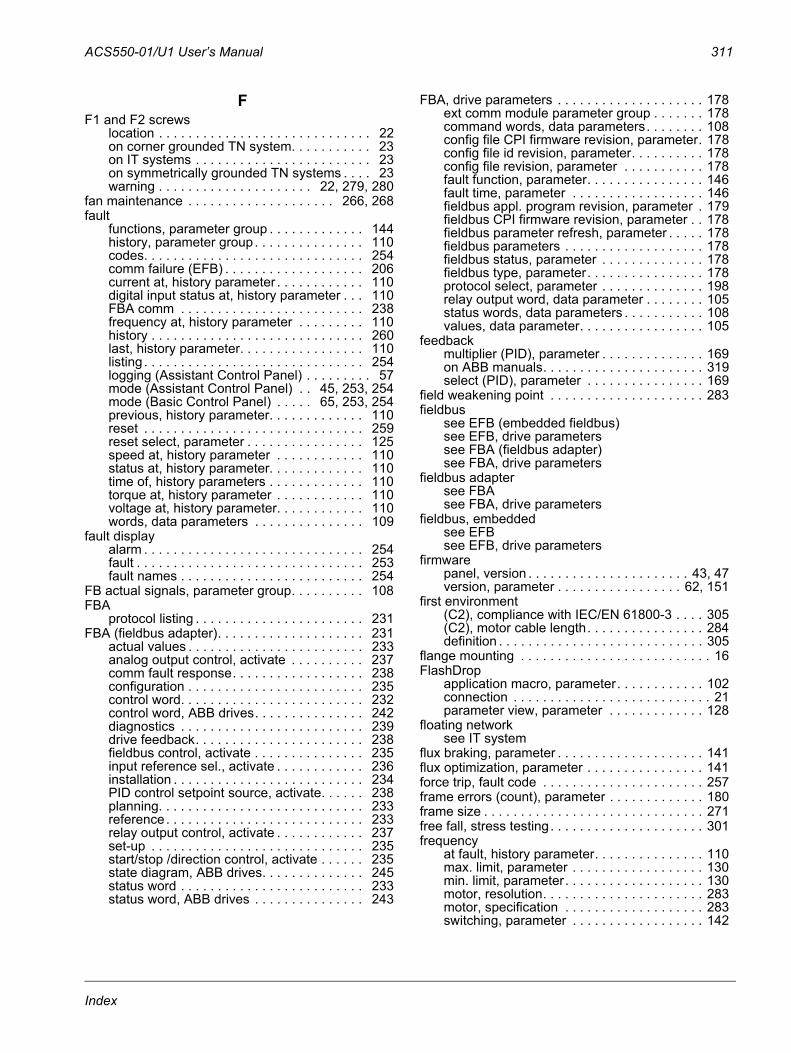
ACS550-01/U1 User’s Manual 311
FF1 and F2 screws
location . . . . . . . . . . . . . . . . . . . . . . . . . . . . . 22on corner grounded TN system. . . . . . . . . . . 23on IT systems . . . . . . . . . . . . . . . . . . . . . . . . 23on symmetrically grounded TN systems . . . . 23warning . . . . . . . . . . . . . . . . . . . . . 22, 279, 280
fan maintenance . . . . . . . . . . . . . . . . . . . . 266, 268fault
functions, parameter group . . . . . . . . . . . . . 144history, parameter group. . . . . . . . . . . . . . . 110codes. . . . . . . . . . . . . . . . . . . . . . . . . . . . . . 254comm failure (EFB) . . . . . . . . . . . . . . . . . . . 206current at, history parameter . . . . . . . . . . . . 110digital input status at, history parameter . . . 110FBA comm . . . . . . . . . . . . . . . . . . . . . . . . . 238frequency at, history parameter . . . . . . . . . 110history . . . . . . . . . . . . . . . . . . . . . . . . . . . . . 260last, history parameter. . . . . . . . . . . . . . . . . 110listing . . . . . . . . . . . . . . . . . . . . . . . . . . . . . . 254logging (Assistant Control Panel) . . . . . . . . . 57mode (Assistant Control Panel) . . 45, 253, 254mode (Basic Control Panel) . . . . . 65, 253, 254previous, history parameter. . . . . . . . . . . . . 110reset . . . . . . . . . . . . . . . . . . . . . . . . . . . . . . 259reset select, parameter . . . . . . . . . . . . . . . . 125speed at, history parameter . . . . . . . . . . . . 110status at, history parameter. . . . . . . . . . . . . 110time of, history parameters . . . . . . . . . . . . . 110torque at, history parameter . . . . . . . . . . . . 110voltage at, history parameter. . . . . . . . . . . . 110words, data parameters . . . . . . . . . . . . . . . 109
fault displayalarm . . . . . . . . . . . . . . . . . . . . . . . . . . . . . . 254fault . . . . . . . . . . . . . . . . . . . . . . . . . . . . . . . 253fault names . . . . . . . . . . . . . . . . . . . . . . . . . 254
FB actual signals, parameter group. . . . . . . . . . 108FBA
protocol listing . . . . . . . . . . . . . . . . . . . . . . . 231FBA (fieldbus adapter). . . . . . . . . . . . . . . . . . . . 231
actual values . . . . . . . . . . . . . . . . . . . . . . . . 233analog output control, activate . . . . . . . . . . 237comm fault response. . . . . . . . . . . . . . . . . . 238configuration . . . . . . . . . . . . . . . . . . . . . . . . 235control word. . . . . . . . . . . . . . . . . . . . . . . . . 232control word, ABB drives. . . . . . . . . . . . . . . 242diagnostics . . . . . . . . . . . . . . . . . . . . . . . . . 239drive feedback. . . . . . . . . . . . . . . . . . . . . . . 238fieldbus control, activate . . . . . . . . . . . . . . . 235input reference sel., activate . . . . . . . . . . . . 236installation . . . . . . . . . . . . . . . . . . . . . . . . . . 234PID control setpoint source, activate. . . . . . 238planning. . . . . . . . . . . . . . . . . . . . . . . . . . . . 233reference. . . . . . . . . . . . . . . . . . . . . . . . . . . 233relay output control, activate . . . . . . . . . . . . 237set-up . . . . . . . . . . . . . . . . . . . . . . . . . . . . . 235start/stop /direction control, activate . . . . . . 235state diagram, ABB drives. . . . . . . . . . . . . . 245status word . . . . . . . . . . . . . . . . . . . . . . . . . 233status word, ABB drives . . . . . . . . . . . . . . . 243
FBA, drive parameters . . . . . . . . . . . . . . . . . . . . 178ext comm module parameter group . . . . . . . 178command words, data parameters. . . . . . . . 108config file CPI firmware revision, parameter. 178config file id revision, parameter. . . . . . . . . . 178config file revision, parameter . . . . . . . . . . . 178fault function, parameter. . . . . . . . . . . . . . . . 146fault time, parameter . . . . . . . . . . . . . . . . . . 146fieldbus appl. program revision, parameter . 179fieldbus CPI firmware revision, parameter . . 178fieldbus parameter refresh, parameter . . . . . 178fieldbus parameters . . . . . . . . . . . . . . . . . . . 178fieldbus status, parameter . . . . . . . . . . . . . . 178fieldbus type, parameter. . . . . . . . . . . . . . . . 178protocol select, parameter . . . . . . . . . . . . . . 198relay output word, data parameter . . . . . . . . 105status words, data parameters . . . . . . . . . . . 108values, data parameter. . . . . . . . . . . . . . . . . 105
feedbackmultiplier (PID), parameter . . . . . . . . . . . . . . 169on ABB manuals. . . . . . . . . . . . . . . . . . . . . . 319select (PID), parameter . . . . . . . . . . . . . . . . 169
field weakening point . . . . . . . . . . . . . . . . . . . . . 283fieldbus
see EFB (embedded fieldbus)see EFB, drive parameterssee FBA (fieldbus adapter)see FBA, drive parameters
fieldbus adaptersee FBAsee FBA, drive parameters
fieldbus, embeddedsee EFBsee EFB, drive parameters
firmwarepanel, version . . . . . . . . . . . . . . . . . . . . . . 43, 47version, parameter . . . . . . . . . . . . . . . . . 62, 151
first environment(C2), compliance with IEC/EN 61800-3 . . . . 305(C2), motor cable length. . . . . . . . . . . . . . . . 284definition . . . . . . . . . . . . . . . . . . . . . . . . . . . . 305
flange mounting . . . . . . . . . . . . . . . . . . . . . . . . . . 16FlashDrop
application macro, parameter. . . . . . . . . . . . 102connection . . . . . . . . . . . . . . . . . . . . . . . . . . . 21parameter view, parameter . . . . . . . . . . . . . 128
floating networksee IT system
flux braking, parameter . . . . . . . . . . . . . . . . . . . . 141flux optimization, parameter . . . . . . . . . . . . . . . . 141force trip, fault code . . . . . . . . . . . . . . . . . . . . . . 257frame errors (count), parameter . . . . . . . . . . . . . 180frame size . . . . . . . . . . . . . . . . . . . . . . . . . . . . . . 271free fall, stress testing. . . . . . . . . . . . . . . . . . . . . 301frequency
at fault, history parameter. . . . . . . . . . . . . . . 110max. limit, parameter . . . . . . . . . . . . . . . . . . 130min. limit, parameter. . . . . . . . . . . . . . . . . . . 130motor, resolution. . . . . . . . . . . . . . . . . . . . . . 283motor, specification . . . . . . . . . . . . . . . . . . . 283switching, parameter . . . . . . . . . . . . . . . . . . 142
Index
312 ACS550-01/U1 User’s Manual
fuses208…240 V drives . . . . . . . . . . . . . . . . . . . 276380…480 V drives . . . . . . . . . . . . . . . . . . . 276500…600 V drives . . . . . . . . . . . . . . . . . . . 277
Ggain (PID), parameter . . . . . . . . . . . . . . . . . . . . 166generic profile, FBA
actual value mapping . . . . . . . . . . . . . . . . . 251actual value scaling . . . . . . . . . . . . . . . . . . 251overview . . . . . . . . . . . . . . . . . . . . . . . . . . . 250reference scaling . . . . . . . . . . . . . . . . . . . . 250technical data . . . . . . . . . . . . . . . . . . . . . . . 250
gland kit . . . . . . . . . . . . . . . . . . . . . . . . . . . . . . . . 19ground
cable/wire requirements . . . . . . . . . . . . . . . 279fault protection . . . . . . . . . . . . . . . . . . . . . . 286
Hhand-auto macro . . . . . . . . . . . . . . . . . . . . . . . . . 78harmonics . . . . . . . . . . . . . . . . . . . . . . . . . . . . . 303heat loss . . . . . . . . . . . . . . . . . . . . . . . . . . . . . . 295hood (IP54 / UL type 12) . . . . . . . . . . . . . . . . 17, 32how to do common tasks
with Assistant Control Panel . . . . . . . . . . . . . 46with Basic Control Panel . . . . . . . . . . . . . . . . 65
II/O settings (Assistant Control Panel) . . . . . . . . . 63I/O, control through . . . . . . . . . . . . . . . . . . . . . . . 40id run
fail, fault code . . . . . . . . . . . . . . . . . . . . . . . 256parameter . . . . . . . . . . . . . . . . . . . . . . . . . . 103performing. . . . . . . . . . . . . . . . . . . . . . . . . . . 41
identification magnetization . . . . . . . . . . . . . . . . 103IEC ratings
see ratingsimpedance grounded network
see IT systemincompatible software, fault code . . . . . . . . . . . 258information on the Internet . . . . . . . . . . . . . . . . 319information, parameter group . . . . . . . . . . . . . . 151input power
cable/wire requirements . . . . . . . . . . . . . . . 278disconnecting device (disconnecting means) 275specifications . . . . . . . . . . . . . . . . . . . . . . . 275
input power connectionIT system . . . . . . . . . . . . . . . . . . . . . . . . . . 280lugs for R6 . . . . . . . . . . . . . . . . . . . . . . . . . 281terminal size . . . . . . . . . . . . . . . . . . . . . . . . 280torque . . . . . . . . . . . . . . . . . . . . . . . . . . . . . 280
installationcheck list . . . . . . . . . . . . . . . . . . . . . . . . . . . . 31compatibility . . . . . . . . . . . . . . . . . . . . . . . . . . 14environment . . . . . . . . . . . . . . . . . . . . . . . . . . 14flow chart . . . . . . . . . . . . . . . . . . . . . . . . . . . . 11location. . . . . . . . . . . . . . . . . . . . . . . . . . . . . . 15mounting drive . . . . . . . . . . . . . . . . . . . . . . . . 18preparation . . . . . . . . . . . . . . . . . . . . . . . . . . . 12procedures . . . . . . . . . . . . . . . . . . . . . . . . . . . 11tools . . . . . . . . . . . . . . . . . . . . . . . . . . . . . . . . 14wiring overview. . . . . . . . . . . . . . . . . . . . . . . . 19
insulation check . . . . . . . . . . . . . . . . . . . . . . . . . . 26integration time (PID), parameter . . . . . . . . . . . . 167integration time, parameter. . . . . . . . . . . . . . . . . 137interlocks, parameter . . . . . . . . . . . . . . . . . . . . . 192internal setpoint (PID), parameter . . . . . . . . . . . 169Internet, information on. . . . . . . . . . . . . . . . . . . . 319IR compensation
frequency, parameter . . . . . . . . . . . . . . . . . . 141parameters . . . . . . . . . . . . . . . . . . . . . . . . . . 141voltage, parameter . . . . . . . . . . . . . . . . . . . . 141
isolation, between AC power source and drive . 275IT system
connections . . . . . . . . . . . . . . . . . . . . . . . . . 280warning about filters . . . . . . . . . . . . . . . . . 6, 288warning about screws at EM1, EM3. . . . . . . . 21warning about screws at F1, F2 . . . . . . . . . . . 22
Jjogging activation, parameter . . . . . . . . . . . . . . . 112
Kkeypad
see control panelkeypad reference select, parameter . . . . . . . . . . 113kWh
counter, data parameter. . . . . . . . . . . . . . . . 104
Llabel
serial number . . . . . . . . . . . . . . . . . . . . . . . . . 12type designation . . . . . . . . . . . . . . . . . . . . . . . 12
language, parameter . . . . . . . . . . . . . . . . . . . . . 102LED
on Assistant Control Panel. . . . . . . 44, 253, 254on drive body . . . . . . . . . . . . . . . . . 21, 253, 254
library, document . . . . . . . . . . . . . . . . . . . . . . . . 319limits, parameter group. . . . . . . . . . . . . . . . . . . . 129
Index
ACS550-01/U1 User’s Manual 313
load analyzerparameter group . . . . . . . . . . . . . . . . . . . . . 183amplitude logger 1, distribution . . . . . . . . . . 184amplitude logger 2 signal base value, par. . 183amplitude logger 2 signal, parameter . . . . . 183amplitude logger 2, distribution . . . . . . . . . . 184loggers reset date . . . . . . . . . . . . . . . . . . . . 184loggers reset time . . . . . . . . . . . . . . . . . . . . 184loggers reset, parameter . . . . . . . . . . . . . . . 183peak value logger filter time, parameter . . . 183peak value logger signal, parameter . . . . . . 183peak value logger, current at peak value . . 184peak value logger, detected peak value . . . 183peak value logger, frequency at peak value 184peak value logger, peak value date . . . . . . 183peak value logger, peak value time. . . . . . . 183peak value logger, voltage at peak value . . 184
load curve, see user load curveload frequency, see user load curveload torque, see user load curveloading package version, parameter . . . . . . . . . 151LOC (local control)
indication on Assistant Control Panel . . . . . . 45indication on Basic Control Panel . . . . . . . . . 64
local control mode lock, parameter . . . . . . . . . . 126lock
control panel access, IP54 . . . . . . . . . . . . . . 32drive control at local control panel. . . . . . . . 126parameters . . . . . . . . . . . . . . . . . . . . . . . . . 125
loggerssee load analyzer
low frequency (PFC), parameters . . . . . . . . . . . 188lugs
for R6 power cables . . . . . . . . . . . . . . . . . . 281ring, crimp-on . . . . . . . . . . . . . . . . . . . . . . . 281terminal, screw-on. . . . . . . . . . . . . . . . . . . . 282
Mmacros
3-wire . . . . . . . . . . . . . . . . . . . . . . . . . . . . . . 75ABB standard (default) . . . . . . . . . . . . . . . . . 74alternate . . . . . . . . . . . . . . . . . . . . . . . . . . . . 76hand-auto . . . . . . . . . . . . . . . . . . . . . . . . . . . 78motor potentiometer . . . . . . . . . . . . . . . . . . . 77PFC. . . . . . . . . . . . . . . . . . . . . . . . . . . . . . . . 80PID control . . . . . . . . . . . . . . . . . . . . . . . . . . 79torque control . . . . . . . . . . . . . . . . . . . . . . . . 81user parameter sets . . . . . . . . . . . . . . . . . . . 83parameter default values. . . . . . . . . . . . . . . . 84parameters not changed . . . . . . . . . . . . . . . . 73
magnetization, identification . . . . . . . . . . . . . . . 103main menu
Assistant Control Panel. . . . . . . . . . . . . . . . . 46Basic Control Panel. . . . . . . . . . . . . . . . . . . . 65
mainssee input power
maintenancecapacitors . . . . . . . . . . . . . . . . . . . . . . . . . . . 269control panel. . . . . . . . . . . . . . . . . . . . . . . . . 269heat sink . . . . . . . . . . . . . . . . . . . . . . . . . . . . 265internal enclosure fan . . . . . . . . . . . . . . . . . . 268intervals . . . . . . . . . . . . . . . . . . . . . . . . . . . . 265main fan . . . . . . . . . . . . . . . . . . . . . . . . . . . . 266triggers, parameter group. . . . . . . . . . . . . . . 143
manualslist of ACS550 manuals . . . . . . . . . . . . . . . . . . 2providing feedback . . . . . . . . . . . . . . . . . . . . 319
mappingactual value, FBA, generic profile. . . . . . . . . 251EFB modbus. . . . . . . . . . . . . . . . . . . . . . . . . 212
materials . . . . . . . . . . . . . . . . . . . . . . . . . . . . . . . 301maximum
frequency, parameter . . . . . . . . . . . . . . . . . . 130torque limit, parameters . . . . . . . . . . . . . . . . 131torque select, parameter . . . . . . . . . . . . . . . 130
mechanicalangle, data parameter . . . . . . . . . . . . . . . . . 106revolutions, data parameter . . . . . . . . . . . . . 106
minimumfrequency, parameter . . . . . . . . . . . . . . . . . . 130torque limit, parameters . . . . . . . . . . . . . . . . 130torque select, parameter . . . . . . . . . . . . . . . 130
modbusEFB addressing, convention . . . . . . . . . . . . 212EFB coils . . . . . . . . . . . . . . . . . . . . . . . . . . . 212EFB discrete inputs . . . . . . . . . . . . . . . . . . . 214EFB holding registers . . . . . . . . . . . . . . . . . . 215EFB input registers. . . . . . . . . . . . . . . . . . . . 215EFB mapping details . . . . . . . . . . . . . . . . . . 212EFB mapping summary . . . . . . . . . . . . . . . . 212EFB supported features . . . . . . . . . . . . . . . . 211EFB technical data . . . . . . . . . . . . . . . . . . . . 211
motorchecking insulation . . . . . . . . . . . . . . . . . . . . . 26compatibility . . . . . . . . . . . . . . . . . . . . . . . . . . 14id run, parameter . . . . . . . . . . . . . . . . . . . . . 103load curve break point frequency . . . . . . . . . 145load curve max., fault parameter . . . . . . . . . 145load curve zero speed load . . . . . . . . . . . . . 145maintenance triggers . . . . . . . . . . . . . . . . . . 143nominal current, parameter . . . . . . . . . . . . . 103nominal frequency, parameter . . . . . . . . . . . 103nominal power, parameter . . . . . . . . . . . . . . 103nominal speed, parameter . . . . . . . . . . . . . . 103nominal voltage, parameter . . . . . . . . . . . . . 103phase, fault code . . . . . . . . . . . . . . . . . . . . . 257requirements . . . . . . . . . . . . . . . . . . . . . . . . . 14stall, fault code . . . . . . . . . . . . . . . . . . . . . . . 256thermal protection. . . . . . . . . . . . . . . . . . . . . 285
motor cablechecking insulation . . . . . . . . . . . . . . . . . . . . . 26length . . . . . . . . . . . . . . . . . . . . . . . . . . . . . . 283max. length. . . . . . . . . . . . . . . . . . . . . . . . . . 283requirements . . . . . . . . . . . . . . . . . . . . . . . . 286requirements, EMC . . . . . . . . . . . . . . . . . . . 287
motor connectionlugs for R6 . . . . . . . . . . . . . . . . . . . . . . . . . . 281terminal size . . . . . . . . . . . . . . . . . . . . . . . . . 280torque . . . . . . . . . . . . . . . . . . . . . . . . . . . . . . 280
Index
314 ACS550-01/U1 User’s Manual
motor controlparameter group . . . . . . . . . . . . . . . . . . . . . 141control mode, parameter. . . . . . . . . . . . . . . 102IR compensation, parameters. . . . . . . . . . . 141
motor potentiometer macro . . . . . . . . . . . . . . . . . 77motor temperature
measure, parameter group . . . . . . . . . . . . . 155alarm limit, parameter . . . . . . . . . . . . . . . . . 156data parameter . . . . . . . . . . . . . . . . . . . . . . 106fault limit, parameter . . . . . . . . . . . . . . . . . . 157overtemperature, fault code . . . . . . . . . . . . 255sensor selection, parameter . . . . . . . . . . . . 156sensor type, parameter . . . . . . . . . . . . . . . . 156thermal protection . . . . . . . . . . . . . . . . . . . . 285thermal protection, fault parameter . . . . . . . 144thermal stress, data parameter . . . . . . . . . . 107thermal time, fault parameter . . . . . . . . . . . 145
motor, auxiliaryaux start order, parameter . . . . . . . . . . . . . 197aux. start delay (PFC), parameter. . . . . . . . 188aux. stop delay (PFC), parameter. . . . . . . . 188number of aux., parameter . . . . . . . . . . . . . 189
motorsseveral . . . . . . . . . . . . . . . . . . . . . . . . 273, 283
mountingdimensions . . . . . . . . . . . . . . . . . . . . . . . . . 297flange . . . . . . . . . . . . . . . . . . . . . . . . . . . . . . 16template . . . . . . . . . . . . . . . . . . . . . . . . . . . . 16
multimotor systems . . . . . . . . . . . . . . . . . . 273, 283MWh
counter, data parameter . . . . . . . . . . . . . . . 106power consumption, maintenance trigger . . 143
NNEMA ratings
see ratingsnoise
random sw. freq. parameter . . . . . . . . . . . . 142NPN. . . . . . . . . . . . . . . . . . . . . . . . . . . . . . . . . . . 25
Ooffset (PID), parameter . . . . . . . . . . . . . . . . . . . 174ok messages (count), parameter. . . . . . . . . . . . 180operating data, parameter group. . . . . . . . . . . . 104operation
Assistant Control Panel . . . . . . . . . . . . . . . . 45Basic Control Panel . . . . . . . . . . . . . . . . . . . 65
OPEX link, fault code . . . . . . . . . . . . . . . . . . . . 256OPEX power, fault code . . . . . . . . . . . . . . . . . . 256options. . . . . . . . . . . . . . . . . . . . . . . . . . . . . . . . . 13
parameter group . . . . . . . . . . . . . . . . . . . . . 198code . . . . . . . . . . . . . . . . . . . . . . . . . . . . . . . 13
outputfrequency, data parameter . . . . . . . . . . . . . 104voltage, data parameter . . . . . . . . . . . . . . . 104wiring, fault code. . . . . . . . . . . . . . . . . . . . . 257
output modeAssistant Control Panel . . . . . . . . . . . . . . . . 49Basic Control Panel . . . . . . . . . . . . . . . . . . . 67
overcurrentautomatic reset, parameter . . . . . . . . . . . . . 148fault code . . . . . . . . . . . . . . . . . . . . . . . . . . 254
overload curvesee user load curve
overspeed, fault code . . . . . . . . . . . . . . . . . . . . . 257overvoltage
control enable, parameter . . . . . . . . . . . . . . 129
Ppanel communication, parameter group . . . . . . . 180panel display variables, parameter group. . . . . . 152panel firmware version . . . . . . . . . . . . . . . . . . 43, 47panel loss, fault code . . . . . . . . . . . . . . . . . . . . . 255parameter
analog input scale, fault code. . . . . . . . . . . . 258analog output scale, fault code . . . . . . . . . . 258change lock . . . . . . . . . . . . . . . . . . . . . . . . . 125descriptions . . . . . . . . . . . . . . . . . . . . . . . . . 102external relay output, fault code . . . . . . . . . . 259fieldbus, fault code . . . . . . . . . . . . . . . . . . . . 259hz rpm, fault code. . . . . . . . . . . . . . . . . . . . . 258listing (ranges, resolutions, defaults) . . . . . . . 87PCU 1 (power control unit), fault code . . . . . 259PCU 2 (power control unit), fault code . . . . . 259PFC IO, fault code . . . . . . . . . . . . . . . . . . . . 259PFC mode, fault code . . . . . . . . . . . . . . . . . 259PFC ref. neg., fault code . . . . . . . . . . . . . . . 258save changes . . . . . . . . . . . . . . . . . . . . . . . . 126table version, parameter . . . . . . . . . . . . . . . 151user load curve, fault code . . . . . . . . . . . . . . 259view, parameter . . . . . . . . . . . . . . . . . . . . . . 128
parameter modeAssistant Control Panel . . . . . . . . . . . . . . . . . 51Basic Control Panel . . . . . . . . . . . . . . . . . . . . 69
parameter restoreAssistant Control Panel . . . . . . . . . . . . . . . . . 60Basic Control Panel . . . . . . . . . . . . . . . . . . . . 71
parity(RS-232), parameter . . . . . . . . . . . . . . . . . . 180errors (count), parameter . . . . . . . . . . . . . . . 180
patents . . . . . . . . . . . . . . . . . . . . . . . . . . . . . . . . 306PE earth
earth fault, parameter. . . . . . . . . . . . . . . . . . 146PE earth connection
terminal size . . . . . . . . . . . . . . . . . . . . . . . . . 280torque . . . . . . . . . . . . . . . . . . . . . . . . . . . . . . 280
peak value loggingsee load analyzer
PELV (Protective Extra Low Voltage) . . . . . . . . . . 25PFC
control, parameter group . . . . . . . . . . . . . . . 186acceleration time, parameter . . . . . . . . . . . . 197aux start order, parameter . . . . . . . . . . . . . . 197aux. motor start delay, parameter . . . . . . . . 188aux. motor stop delay, parameter . . . . . . . . 188deceleration time, parameter . . . . . . . . . . . . 197enable, parameter . . . . . . . . . . . . . . . . . . . . 196low frequency, parameters. . . . . . . . . . . . . . 188macro . . . . . . . . . . . . . . . . . . . . . . . . . . . . . . . 80number of aux. motors, parameter. . . . . . . . 189number of motors parameter . . . . . . . . . . . . 197reference step, parameters . . . . . . . . . . . . . 186start delay, parameter . . . . . . . . . . . . . . . . . 196start frequency, parameters . . . . . . . . . . . . . 187
Index
ACS550-01/U1 User’s Manual 315
PIDprocess sets, parameter groups . . . . . . . . . 165external / trimming, parameter group . . . . . 1740% (actual signal), parameter . . . . . . . . . . . 168100% (actual signal), parameter . . . . . . . . . 168actual input select, parameters . . . . . . . . . . 170actual value max., parameters . . . . . . . . . . 170actual value min., parameters . . . . . . . . . . . 170adjustment procedure . . . . . . . . . . . . . . . . . 166comm value 1, data parameter . . . . . . . . . . 107comm value 2, data parameter . . . . . . . . . . 107control macro . . . . . . . . . . . . . . . . . . . . . . . . 79correction source, parameter . . . . . . . . . . . 175decimal point (actual signal), parameter . . . 167derivation filter, parameter . . . . . . . . . . . . . 167derivation time, parameter . . . . . . . . . . . . . 167deviation, data parameter . . . . . . . . . . . . . . 105error feedback inversion, parameter . . . . . . 167external source activate, parameter . . . . . . 174feedback multiplier, parameter . . . . . . . . . . 169feedback select, parameter. . . . . . . . . . . . . 169feedback, data parameter . . . . . . . . . . . . . . 105gain, parameter . . . . . . . . . . . . . . . . . . . . . . 166integration time, parameter . . . . . . . . . . . . . 167internal setpoint, parameter . . . . . . . . . . . . 169offset, parameter . . . . . . . . . . . . . . . . . . . . . 174output, data parameter . . . . . . . . . . . . . . . . 105parameter set select, parameter . . . . . . . . . 172scaling (0…100%), parameters. . . . . . . . . . 168setpoint maximum, parameter. . . . . . . . . . . 169setpoint minimum, parameter . . . . . . . . . . . 169setpoint select, parameter. . . . . . . . . . . . . . 168setpoint source, EFB comm activate. . . . . . 206setpoint source, FBA comm, activate . . . . . 238setpoint, data parameter . . . . . . . . . . . . . . . 105sleep delay, parameter . . . . . . . . . . . . . . . . 171sleep level, parameter. . . . . . . . . . . . . . . . . 171sleep selection, parameter . . . . . . . . . . . . . 170trim mode, parameter . . . . . . . . . . . . . . . . . 174trim scale, parameter . . . . . . . . . . . . . . . . . 174units (actual signal), parameter. . . . . . . . . . 167wake-up delay, parameter. . . . . . . . . . . . . . 171wake-up deviation, parameter. . . . . . . . . . . 171
PID controlleradvanced set-up . . . . . . . . . . . . . . . . . . . . . 166basic set-up. . . . . . . . . . . . . . . . . . . . . . . . . 165
planningEFB comm . . . . . . . . . . . . . . . . . . . . . . . . . 200FBA comm . . . . . . . . . . . . . . . . . . . . . . . . . 233
PNP . . . . . . . . . . . . . . . . . . . . . . . . . . . . . . . . . . . 25power
consumption (MWh) maintenance trigger . . 143data parameter . . . . . . . . . . . . . . . . . . . . . . 104
previous faults, history parameters . . . . . . . . . . 110process PID sets, parameter groups . . . . . . . . . 165process variables, data parameter . . . . . . . . . . 106product
inquiries. . . . . . . . . . . . . . . . . . . . . . . . . . . . 319training . . . . . . . . . . . . . . . . . . . . . . . . . . . . 319
profiles, EFB comm . . . . . . . . . . . . . . . . . . . . . . 212proportional gain, parameter . . . . . . . . . . . . . . . 137
protectioncircuit, required w/ chopper . . . . . . . . . . . . . 292disconnecting device (disconnecting means) 275enclosure standard. . . . . . . . . . . . . . . . . . . . 303environmental. . . . . . . . . . . . . . . . . . . . . . . . 300motor thermal . . . . . . . . . . . . . . . . . . . . . . . . 285
PT100 temperature sensor . . . . . . . . . . . . . . . . . 156PTC temperature sensor. . . . . . . . . . . . . . . . . . . 156pump power
see energy saving
Rradiation limits, conducted
EN 61800-3 . . . . . . . . . . . . . . . . . . . . . . . . . 288ramp pair (accel/decel), parameter . . . . . . . . . . . 135range listing for parameters . . . . . . . . . . . . . . . . . 87ratings . . . . . . . . . . . . . . . . . . . . . . . . . . . . . . . . . 271reference
select, parameter group . . . . . . . . . . . . . . . . 113corrections for parameter values . . . . . . . . . 114keypad control, parameter . . . . . . . . . . . . . . 113maximum, parameters . . . . . . . . . . . . . . . . . 115minimum, parameters. . . . . . . . . . . . . . . . . . 115mode (Basic Control Panel) . . . . . . . . . . . . . . 68select source, parameter . . . . . . . . . . . . . . . 113step (PFC), parameters . . . . . . . . . . . . . . . . 186
reference scalingEFB, ABB drives profile . . . . . . . . . . . . . . . . 228FBA, ABB drives profile . . . . . . . . . . . . . . . . 246FBA, generic profile . . . . . . . . . . . . . . . . . . . 250
reference settingAssistant Control Panel . . . . . . . . . . . . . . . . . 50Basic Control Panel . . . . . . . . . . . . . . . . . . . . 68
regulator by-pass control, parameter . . . . . . . . . 196relative humidity
environment limit . . . . . . . . . . . . . . . . . . . . . 300shipping limit. . . . . . . . . . . . . . . . . . . . . . . . . 300
relay outputparameter group. . . . . . . . . . . . . . . . . . . . . . 120activation condition parameters . . . . . . . . . . 120off-delay, parameters . . . . . . . . . . . . . . . . . . 121on-delay, parameters . . . . . . . . . . . . . . . . . . 121status, data parameter . . . . . . . . . . . . . . . . . 105
relays, specifications. . . . . . . . . . . . . . . . . . . . . . 293REM (remote control)
indication on Assistant Control Panel. . . . . . . 45indication on Basic Control Panel. . . . . . . . . . 64
remove cover . . . . . . . . . . . . . . . . . . . . . . . . . . . . 17reset, automatic
parameter group. . . . . . . . . . . . . . . . . . . . . . 148analog input less than min., parameter . . . . 148delay time, parameter. . . . . . . . . . . . . . . . . . 148external fault, parameter . . . . . . . . . . . . . . . 148number of trials, parameter . . . . . . . . . . . . . 148overcurrent, parameter. . . . . . . . . . . . . . . . . 148trial time, parameter . . . . . . . . . . . . . . . . . . . 148undervoltage, parameter . . . . . . . . . . . . . . . 148
resolution listing for parameters . . . . . . . . . . . . . . 87resonance (avoiding)
select, parameter . . . . . . . . . . . . . . . . . . . . . 140revolution counter, data parameter . . . . . . . . . . . 106revolutions, mechanical, data parameter . . . . . . 106
Index
316 ACS550-01/U1 User’s Manual
ring lugs. . . . . . . . . . . . . . . . . . . . . . . . . . . . . . . 281RS-232
baud rate, parameter . . . . . . . . . . . . . . . . . 180parity, parameter. . . . . . . . . . . . . . . . . . . . . 180station id, parameter . . . . . . . . . . . . . . . . . . 180
RS-232 countsbuffer overruns, parameter . . . . . . . . . . . . . 180CRC errors, parameter . . . . . . . . . . . . . . . . 180frame errors, parameter . . . . . . . . . . . . . . . 180ok messages, parameter . . . . . . . . . . . . . . 180parity errors, parameter . . . . . . . . . . . . . . . 180
RS485 comm. . . . . . . . . . . . . . . . . . . . . . . . . . . 200run enable source select, parameter. . . . . . . . . 125run time
data parameter . . . . . . . . . . . . . . . . . . 104, 106maintenance trigger . . . . . . . . . . . . . . . . . . 143
Ssafety. . . . . . . . . . . . . . . . . . . . . . . . . . . . . . . . . . . 5save changes parameter. . . . . . . . . . . . . . . . . . 126saving, energy
see energy savingscalar:frequency mode . . . . . . . . . . . . . . . . . . . 102scaling
actual value, FBA, ABB drives profile . . . . . 249actual value, FBA, generic profile . . . . . . . . 251actual values, EFB comm . . . . . . . . . . . . . . 207reference, EFB, ABB drives profile . . . . . . . 228reference, FBA, ABB drives profile . . . . . . . 246reference, FBA, generic profile . . . . . . . . . . 250
screw-on terminal lugs . . . . . . . . . . . . . . . . . . . 282s-curve ramp, parameter . . . . . . . . . . . . . . . . . . 135second environment
(C3), compliance with IEC/EN 61800-3 . . . 305(C3), motor cable length . . . . . . . . . . . . . . . 284definition . . . . . . . . . . . . . . . . . . . . . . . . . . . 305
sensor type, parameter . . . . . . . . . . . . . . . . . . . 156sensorless vector control mode. . . . . . . . . . . . . 102serial 1 error (fault code 28) . . . . . . . . . . . . . . . 210serial 1 error, fault code. . . . . . . . . . . . . . . . . . . 257serial communication
see EFB (embedded fieldbus)see EFB, drive parameterssee FBA (fieldbus adapter)see FBA, drive parameters
serial number. . . . . . . . . . . . . . . . . . . . . . . . . 12, 13service . . . . . . . . . . . . . . . . . . . . . . . . . . . . . . . . 319setpoint maximum (PID), parameter . . . . . . . . . 169setpoint minimum (PID), parameter . . . . . . . . . 169setpoint select (PID), parameter . . . . . . . . . . . . 168shock, stress testing . . . . . . . . . . . . . . . . . . . . . 301short circuit, fault code . . . . . . . . . . . . . . . . . . . 255single phase supply
connection . . . . . . . . . . . . . . . . . . . . . . . . . . 19derating. . . . . . . . . . . . . . . . . . . . . . . . . . . . 274
sleep selection (PID), parameter. . . . . . . . . . . . 170slip compensation ratio, parameter . . . . . . . . . . 142soft keys (Assistant Control Panel) . . . . . . . . . . . 44
specificationscontrol connections . . . . . . . . . . . . . . . . . . . 293input power. . . . . . . . . . . . . . . . . . . . . . . . . . 275mains . . . . . . . . . . . . . . . . . . . . . . . . . . . . . . 275
speedand direction (signed), data parameter . . . . 104at fault, history parameter . . . . . . . . . . . . . . 110data parameter. . . . . . . . . . . . . . . . . . . . . . . 104max. limit, parameter . . . . . . . . . . . . . . . . . . 129min. limit, parameter. . . . . . . . . . . . . . . . . . . 129
speed controlparameter group. . . . . . . . . . . . . . . . . . . . . . 137acceleration compensation, parameter . . . . 138automatic tuning, parameter . . . . . . . . 137, 138derivation time, parameter . . . . . . . . . . . . . . 137integration time, parameter . . . . . . . . . . . . . 137proportional gain, parameter . . . . . . . . . . . . 137vector:speed mode. . . . . . . . . . . . . . . . . . . . 102
speed, constantparameter group. . . . . . . . . . . . . . . . . . . . . . 116digital input selection parameter . . . . . . . . . 116parameters . . . . . . . . . . . . . . . . . . . . . . . . . . 117
stallfrequency, fault parameter . . . . . . . . . . . . . . 146function, fault parameter . . . . . . . . . . . . . . . 146region . . . . . . . . . . . . . . . . . . . . . . . . . . . . . . 146time, fault parameter . . . . . . . . . . . . . . . . . . 146
standards . . . . . . . . . . . . . . . . . . . . . . . . . . . . . . 303C22.2 No. 14 . . . . . . . . . . . . . . . . . . . . . . . . 303CE marking . . . . . . . . . . . . . . . . . . . . . . . . . 303CSA marking . . . . . . . . . . . . . . . . . . . . . . . . 304C-Tick marking . . . . . . . . . . . . . . . . . . . . . . . 303EN 50178 . . . . . . . . . . . . . . . . . . . . . . . . . . . 303IEC 60664-1 . . . . . . . . . . . . . . . . . . . . . . . . . 303IEC/EN 60204-1 . . . . . . . . . . . . . . . . . . . . . . 303IEC/EN 60529 . . . . . . . . . . . . . . . . . . . . . . . 303IEC/EN 61000-3-12 . . . . . . . . . . . . . . . . . . . 303IEC/EN 61800-3 . . . . . . . . . . . . . . . . . . . . . . 303IEC/EN 61800-5-1 . . . . . . . . . . . . . . . . . . . . 303UL 508C . . . . . . . . . . . . . . . . . . . . . . . . . . . . 303UL marking. . . . . . . . . . . . . . . . . . . . . . . . . . 304
startparameter group. . . . . . . . . . . . . . . . . . . . . . 132aux. motor (PFC), parameters . . . . . . . . . . . 187aux. motor delay. . . . . . . . . . . . . . . . . . . . . . 188control, EFB comm. . . . . . . . . . . . . . . . . . . . 203control, FBA comm. . . . . . . . . . . . . . . . . . . . 235DC magnetizing time, parameter . . . . . . . . . 132delay (PFC), parameter . . . . . . . . . . . . . . . . 196delay, parameter . . . . . . . . . . . . . . . . . . . . . 134frequency (PFC), parameters. . . . . . . . . . . . 187function, parameter . . . . . . . . . . . . . . . . . . . 132inhibit, parameter . . . . . . . . . . . . . . . . . . . . . 133select enable source, parameter . . . . . . . . . 127torque boost current, parameter. . . . . . . . . . 133
start modeautomatic . . . . . . . . . . . . . . . . . . . . . . . . . . . 132automatic torque boost. . . . . . . . . . . . . . . . . 132DC magnetizing . . . . . . . . . . . . . . . . . . . . . . 132flying start. . . . . . . . . . . . . . . . . . . . . . . . . . . 132
start/stopparameter group. . . . . . . . . . . . . . . . . . . . . . 132with Assistant Control Panel . . . . . . . . . . . . . 48with Basic Control Panel . . . . . . . . . . . . . . . . 66
Index
ACS550-01/U1 User’s Manual 317
start/stop/dir, parameter group . . . . . . . . . . . . . 111starting order counter . . . . . . . . . . . . . . . . . . . . 191start-up
assistant . . . . . . . . . . . . . . . . . . . . . . . . . 38, 53data, parameter group. . . . . . . . . . . . . . . . . 102guided, Assistant Control Panel . . . . . . . . . . 38limited, Assistant or Basic Control Panel . . . 33
state diagramcomm (EFB) . . . . . . . . . . . . . . . . . . . . . . . . 227comm, ABB drives. . . . . . . . . . . . . . . . . . . . 245
station id (RS-232), parameter . . . . . . . . . . . . . 180status at fault, history parameter . . . . . . . . . . . . 110status word
ABB drives, FBA, description . . . . . . . . . . . 243EFB comm, definition . . . . . . . . . . . . . . . . . 222FBA . . . . . . . . . . . . . . . . . . . . . . . . . . . . . . . 233FBA generic profile . . . . . . . . . . . . . . . . . . . 250
stopparameter group . . . . . . . . . . . . . . . . . . . . . 132aux. motor (PFC), parameters . . . . . . . . . . 188aux. motor delay . . . . . . . . . . . . . . . . . . . . . 188DC brake time, parameter. . . . . . . . . . . . . . 133DC current control, parameter. . . . . . . . . . . 132DC current ref., parameter . . . . . . . . . . . . . 133emergency devices . . . . . . . . . . . . . . . . . . . 277emergency select, parameter . . . . . . . . . . . 133flux braking, parameter . . . . . . . . . . . . . . . . 141function, parameter . . . . . . . . . . . . . . . . . . . 132
stress tests . . . . . . . . . . . . . . . . . . . . . . . . . . . . 301supervision
parameter group . . . . . . . . . . . . . . . . . . . . . 149parameter low limit, parameters . . . . . . . . . 149parameter selection, parameters . . . . . . . . 149
supply phase, fault code . . . . . . . . . . . . . . . . . . 256switching frequency . . . . . . . . . . . . . . . . . . . . . . 283
control, parameter . . . . . . . . . . . . . . . . . . . . 142derating . . . . . . . . . . . . . . . . . . . . . . . . . . . . 274parameter . . . . . . . . . . . . . . . . . . . . . . . . . . 142
symmetrically grounded networksee corner grounded TN system
symmetrically grounded TN system . . . . . . . . . 279system controls, parameter group . . . . . . . . . . . 125
Ttemperature derating . . . . . . . . . . . . . . . . . . . . . 274template, mounting . . . . . . . . . . . . . . . . . . . . . . . 16terminal lugs . . . . . . . . . . . . . . . . . . . . . . . . . . . 282terminals
control, description . . . . . . . . . . . . . . . . . . . . 24control, specifications . . . . . . . . . . . . . . . . . 294location diagram, R1…R4. . . . . . . . . . . . . . . 21location diagram, R5/R6 . . . . . . . . . . . . . . . . 22
termination. . . . . . . . . . . . . . . . . . . . . . . . . . . . . 201test date, parameter . . . . . . . . . . . . . . . . . . . . . 151thermal fail, fault code . . . . . . . . . . . . . . . . . . . . 256three-wire sensor/transmitter, connection example 82time and date setting (Assistant Control Panel) . 58
timed functionsparameter group. . . . . . . . . . . . . . . . . . . . . . 158autochange, parameter . . . . . . . . . . . . . . . . 197booster, parameter . . . . . . . . . . . . . . . . . . . . 160enable, parameter . . . . . . . . . . . . . . . . . . . . 159source, parameter . . . . . . . . . . . . . . . . . . . . 160speed control . . . . . . . . . . . . . . . . . . . . . . . . 118start time, parameter . . . . . . . . . . . . . . . . . . 159stop time, parameter . . . . . . . . . . . . . . . . . . 159
timed mode, parameter. . . . . . . . . . . . . . . . . . . . 118TN-S system . . . . . . . . . . . . . . . . . . . . . . . . . . . . 279tools . . . . . . . . . . . . . . . . . . . . . . . . . . . . . . . . . . . 14top cover, see hoodtorque
at fault, history parameter. . . . . . . . . . . . . . . 110boost current, parameter . . . . . . . . . . . . . . . 133data parameter . . . . . . . . . . . . . . . . . . . . . . . 104max. limit select, parameter . . . . . . . . . . . . . 130max. limit, parameter . . . . . . . . . . . . . . . . . . 131min. limit select, parameter . . . . . . . . . . . . . 130min. limit, parameters . . . . . . . . . . . . . . . . . . 130ramp down, parameter . . . . . . . . . . . . . . . . . 139ramp up, parameter . . . . . . . . . . . . . . . . . . . 139
torque controlparameter group. . . . . . . . . . . . . . . . . . . . . . 139macro . . . . . . . . . . . . . . . . . . . . . . . . . . . . . . . 81ramp down, parameter . . . . . . . . . . . . . . . . . 139ramp up, parameter . . . . . . . . . . . . . . . . . . . 139vector:torque mode . . . . . . . . . . . . . . . . . . . 102
training . . . . . . . . . . . . . . . . . . . . . . . . . . . . . . . . 319trim
mode (PID), parameter. . . . . . . . . . . . . . . . . 174scale (PID), parameter . . . . . . . . . . . . . . . . . 174
two-wire sensor/transmitter, connection example. 82type code
see type designationtype designation . . . . . . . . . . . . . . . . . . . . . . . 12, 13
UU/f ratio, parameter . . . . . . . . . . . . . . . . . . . . . . . 141UL/CSA markings . . . . . . . . . . . . . . . . . . . . . . . . 304underload curve
see user load curveundervoltage
automatic reset, parameter . . . . . . . . . . . . . 148control enable, parameter . . . . . . . . . . . . . . 129
ungrounded networksee IT system
units (PID), parameter. . . . . . . . . . . . . . . . . . . . . 167unknown drive type, fault code . . . . . . . . . . . . . . 258unpacking drive. . . . . . . . . . . . . . . . . . . . . . . . . . . 12unsymmetrically grounded networks
see corner grounded TN systemuser load curve
parameter group. . . . . . . . . . . . . . . . . . . . . . 162fault code . . . . . . . . . . . . . . . . . . . . . . . . . . . 258frequency, parameters . . . . . . . . . . . . . 162, 163function, parameter . . . . . . . . . . . . . . . . . . . 162mode, parameter . . . . . . . . . . . . . . . . . . . . . 162time, parameter . . . . . . . . . . . . . . . . . . . . . . 162torque, parameters . . . . . . . . . . . . . . . . 162, 163
Index
318 ACS550-01/U1 User’s Manual
user parameter set . . . . . . . . . . . . . . . . . . . . . . . 83change control, parameter . . . . . . . . . . . . . 126download . . . . . . . . . . . . . . . . . . . . . . . . . . . 60
Vvector:
speed mode . . . . . . . . . . . . . . . . . . . . . . . . 102torque mode . . . . . . . . . . . . . . . . . . . . . . . . 102
versionfirmware, parameter . . . . . . . . . . . . . . . 62, 151loading package, parameter . . . . . . . . . . . . 151panel firmware . . . . . . . . . . . . . . . . . . . . 43, 47parameter table, parameter . . . . . . . . . . . . 151
vibration, stress testing . . . . . . . . . . . . . . . . . . . 301voltage
at fault, history parameter . . . . . . . . . . . . . . 110rating code . . . . . . . . . . . . . . . . . . . . . . . . . . 13
voltage/frequency ratio, parameter . . . . . . . . . . 141
Wwake-up
delay (PID), parameter . . . . . . . . . . . . . . . . 171deviation (PID), parameter . . . . . . . . . . . . . 171
warningautomatic start up . . . . . . . . . . . . . . . . . . . . . . 6dangerous voltages . . . . . . . . . . . . . . . . . . . . 5disconnecting device (disconnecting means) . 6ELV (Extra Low Voltage) . . . . . . . . . . . . . . . 25EM1, EM3, F1 and F2 screws. . . . . . . . . . . . . 6filter on corner grounded TN system. . . . . . . . 6filter on IT system . . . . . . . . . . . . . . . . . . . . . . 6high temperatures. . . . . . . . . . . . . . . . . . . . . . 6listing. . . . . . . . . . . . . . . . . . . . . . . . . . . . . . . . 5not field repairable . . . . . . . . . . . . . . . . . . . . . 6parallel control connections . . . . . . . . . . . . . . 5qualified installer . . . . . . . . . . . . . . . . . . . . . . . 5
weight . . . . . . . . . . . . . . . . . . . . . . . . . . . . . . . . 299wiring
control . . . . . . . . . . . . . . . . . . . . . . . . . . . . . . 24fault, parameter. . . . . . . . . . . . . . . . . . . . . . 147installation. . . . . . . . . . . . . . . . . . . . . . . . . . . 26installation steps, IP21/cables . . . . . . . . . . . 27installation steps, IP21/conduit . . . . . . . . . . . 28installation steps, IP54/cables . . . . . . . . . . . 29installation steps, IP54/conduit . . . . . . . . . . . 30overview . . . . . . . . . . . . . . . . . . . . . . . . . . . . 19requirements, general . . . . . . . . . . . . . . . . . . 19
XYZzero pulse
detected, data parameter . . . . . . . . . . . . . . 106enable, parameter. . . . . . . . . . . . . . . . . . . . 177
zero speeddelay, parameter . . . . . . . . . . . . . . . . . . . . . 134load, fault parameter . . . . . . . . . . . . . . . . . . 145
Index

Further information
Product and service inquiriesAddress any inquiries about the product to your local ABB representative, quoting the type designation and serial number of the unit in question. A listing of ABB sales, support and service contacts can be found by navigating to www.abb.com/drives and selecting Sales, Support and Service Network.
Product trainingFor information on ABB product training, navigate to www.abb.com/drives and select Training courses.
Providing feedback on ABB Drives manualsYour comments on our manuals are welcome. Go to www.abb.com/drives and select Document Library – Manuals feedback form (LV AC drives).
Document library on the InternetYou can find manuals and other product documents in PDF format on the Internet. Go to www.abb.com/drives and select Document Library. You can browse the library or enter selection criteria, for example a document code, in the search field.
ABB Inc.Automation TechnologiesDrives & Motors16250 West Glendale DriveNew Berlin, WI 53151USATelephone +1 262 785-3200
+1 800-HELP-365Fax +1 262 780-5135
ABB Beijing Drive Systems Co. Ltd.No. 1, Block D, A-10 Jiuxianqiao BeiluChaoyang DistrictBeijing, P.R. China, 100015Telephone +86 10 5821 7788Fax +86 10 5821 7618Internet www.abb.com
ABB OyAC DrivesP.O. Box 184FI-00381 HELSINKIFINLANDTelephone +358 10 22 11Fax +358 10 22 22681Internet www.abb.com
ABB Ltd.Plot No 5 & 6II PhasePeenya Industrial AreaBangalore 560 058INDIATelephone +91 80 2294 9585Fax +91 80 2294 9389
3AFE
6480
4588
(3A
UA
0000
0014
18) R
ev G
/ E
NE
FFE
CTI
VE
: 200
9-07
-07
SU
PE
RS
ED
ES
: 3A
FE64
8045
88 (3
AU
A00
0000
1418
) Rev
F 2
007-
04-1
6


