72
IT EN ISTRUZIONI DI ASSEMBLAGGIO, USO E MANUTENZIONE Istruzioni originali in lingua italiana ASSEMBLY, USE AND MAINTENANCE INSTRUCTIONS Translation of the original instructions in Italian
IT EN
ISTRUZIONI DI ASSEMBLAGGIO, USO E MANUTENZIONEIstruzioni originali in lingua italiana
ASSEMBLY, USE AND MAINTENANCE INSTRUCTIONSTranslation of the original instructions in Italian

N.B.: Il documento seguente è un FAC-SIMILE. La dichiarazione di incorporazione originale viene fornita a parte.NOTE: The following document is a FACSIMILE. The original declaration of incorporation is supplied separately.
Identificazione Costruttore e "Quasi-macchina" / Manufacturer and partly completed machinery identification

PER I PAESI CEE
• Il gruppo motore endotermico , in base alla Direttiva Europea 2006/42/CE, è da considerarsi una quasi-macchina.• Il Costruttore Valdinoci Luigi S.p.A vieta la messa in servizio della "quasi-macchina" fino a quando la macchina finale in cui deve essere
incorporata non è stata dichiarata conforme alle disposizioni della Direttiva 2006/42/CE.• Il presente manuale di Assemblaggio, Uso e Manutenzione è rivolto ai tecnici installatori e deve essere incorporato nella nuova documentazione
tecnica realizzata appositamente per l'assieme: MACCHINA + QUASI-MACCHINA (gruppo motore endotermico).
FOR ECC COUNTRIES
• According to European Directive 2006/42/EC, an internal combustion engine unit is to be considered as partly completed machinery.• The Manufacturer, Valdinoci Luigi S.p.A, prohibits commissioning of the partly completed machinery until the final machine into which it is to
be incorporated has been declared compliant with the provisions of Directive 2006/42/EC.• This Assembly, Use and Maintenance Manual is intended for the installer and must be included in the new technical documentation specifically
provided for the assembly: MACHINE + PARTLY COMPLETED MACHINERY (internal combustion engine).
RPMGiri/1’
Specification NumberCodice Cliente
EU Approval CodeOmologazione
Machine ModelTipo Macchina
Engine ModelTipo Motore
Serial NumberMatricola Identificazione Motore
s/n
rpmXX XX XXXX
XX XX XXXX
XXXX
XXXXXXe9 • 97/68/CE • 00/000xx • xxxx •xx
Xx 0.00 xxx xxx xx
Model
Spec.
Engine ModelTipo Motore
RPMGiri/1’
Serial NumberMatricola Identificazione Motore
Specification NumberCodice Cliente
VALDINOCI LUIGI S.P.A.,

IDENTIFICAZIONE COSTRUTTORE E QUASI-MACCHINA ................................................................1
INDICE RIASSUNTIVO OPERAZIONI DI MANUTENZIONE ....................................................................3
INFORMAZIONI GENERALI ...................................................4
Premessa................................................................................4
INFORMAZIONI SULLA SICUREZZA ...................................5
Impieghi ammessi e uso improprio .....................................5
Avvertenze di sicurezza ........................................................5
Simbologia di redazione .......................................................6
Sicurezza per l'impatto ambientale ......................................7
Ubicazione dei segnali di sicurezza sul motore .................8
CARATTERISTICHE TECNICHE ...........................................9
Dimensioni .............................................................................9
PRIMA DELL'AVVIAMENTO ................................................12
MOVIMENTAZIONE ..............................................................12
SMONTAGGIO COPERCHIO SUPERIORE SILENCE ........13
CIRCUITI ...............................................................................14
Batterie .................................................................................14
Circuito elettrico ..................................................................15
INFORMAZIONI TECNICHE .................................................16
Olio ........................................................................................16
Carburante ...........................................................................18
Liquido refrigerante .............................................................20
Descrizione delle spie .........................................................21
AVVIAMENTO / ARRESTO ..................................................23
Avviamento ..........................................................................23
Rodaggio ..............................................................................24
Arresto ..................................................................................24
MANUTENZIONE ..................................................................24
Manutenzione (dopo le prime 50 ore) ...............................24
Manutenzione (ogni 10 ore) ...............................................24
Manutenzione (ogni 300 ore o 1 anno) ............................26
Manutenzione (ogni 600 ore) .............................................27
Manutenzione (ogni 1200 ore o 2 anni) ............................29
Manutenzione speciale (ogni 600 ore) ...............................30
Manutenzione speciale (ogni 1200 ore) .............................30
Manutenzione speciale (dopo 5000 ore)............................30
Manutenzione speciale (dopo 10000 ore)..........................30
IMMAGAZZINAGGIO ............................................................31
Immagazzinaggio .................................................................31
Stoccaggio motore (non installato) ...................................31
Trattamento protettivo ........................................................31
Messa in servizio motore dopo il trattamento protettivo ..............................................................................32
ANOMALIE ...........................................................................33
Tabelle probabili anomalie in funzione dei sintomi .........33
INDICE

33
IT
Gli intervalli di manutenzione preventiva qui riportati sono validi per l'utilizzo del motore fatto funzionare in condizioni di eserci-zio normali e con carburante e olio conformi alle caratteristiche tecniche riportate in questo manuale.
CONTROLLO
DESCRIZIONE OPERAZIONEFREQUENZA DI INTERVENTO (ORE)
PAG.10 300 600 1200 5000
Livello olio motore 24Filtro aria (***) 25Livello liquido di raffreddamento 26Tensione cinghia alternatore (*) 26Manicotti in gomma (asp. Aria/liquido di raffreddamento) (*) 27Efficienza radiatore @ 28
Registro gioco valvole @ 30
Taratura e pulizia iniettori 30
(*) - In caso di scarso utilizzo: 12 mesi. (**) - In caso di scarso utilizzo: 24 mesi.
(***) - Il periodo di tempo che deve intercorrere prima di pulire o sostituire l’elemento filtrante è subordinato all’ambiente in cui opera il motore. In condizioni ambientali molto polverose il filtro dell’aria deve essere pulito e sostituito più spesso. @ Manutenzione da eseguire solo presso stazioni di servizio
SOSTITUZIONE
DESCRIZIONE OPERAZIONEFREQUENZA DI INTERVENTO (ORE)
PAG.125 300 600 1200 5000
Olio motore (*) 26Filtro olio (*) 27Filtro carburante (*) 27Cinghia alternatore 27Manicotti circuito di raffreddamento 27Liquido di raffreddamento (*)@ 29
Cinghia di distribuzione 30
REVISIONE
DESCRIZIONE OPERAZIONEFREQUENZA DI INTERVENTO (ORE)
PAG.300 600 1200 5000 10000
Revisione Parziale @ 30
Revisione Generale @ 30
INDICE RIASSUNTIVO OPERAZIONI DI PRIMA MANUTENZIONE
RIEPILOGO INTERVENTI DI MANUTENZIONE IN RODAGGIO DESCRIZIONE OPERAZIONE
DOPO LE PRIME 50 OREPAG.
Sostituzione olio motore 26Sostituzione filtro olio 27
Indice riassuntivo operazioni di manutenzione
MANUTENZIONE ORDINARIA
IT

4
IT
Premessa
Abbiamo cercato di fare il possibile per dare informazioni tecniche accurate e aggiornate all’interno di questo manuale. Lo sviluppo dei motori è tuttavia continuo, pertanto le informazioni contenute all’interno di questa pubblicazione sono soggette a variazioni senza obbligo di preavviso.Le informazioni qui riportate sono di proprietà esclusiva della Valdinoci Luigi S.p.A. Pertanto non sono permesse riproduzioni o ristampe nè parziali nè totali senza il permesso espresso della Valdinoci Luigi S.p.A.
Le informazioni presentate in questo manuale presuppongono che:1 - le persone che effettuano un lavoro di servizio su motori siano adeguatamente addestrate ed attrezzate per provvedere in modo sicuro e professionale alle operazioni necessarie;2 - le persone che effettuano un lavoro di servizio su motori posseggano un’adeguata manualità e gli attrezzi speciali per provvedere in modo sicuro e professionale alle operazioni necessarie;3 - le persone che effettuano un lavoro di servizio su motori abbiano letto le specifiche informazioni riguardanti le già citate operazioni Service e abbiano chiaramente capito le operazioni da eseguire.
Note Generali Service
1 - Utilizzare solo ricambi originali. L'uso di particolari non originali potrebbe causare prestazioni non corrette e scarsa longevità.
2 - Tutti i dati riportati sono in formato metrico, cioè le dimensioni sono espresse in millimetri (mm), la coppia è espressa in Newton-metri (Nm), il peso è espresso in chilogrammi (Kg), il volume è espresso in litri o centimetri cubi (cc) e la pressione è espressa in unità barometriche (bar).
Clausola di Garanzia
La Valdinoci Luigi S.p.A garantisce i prodotti di sua fabbricazione da difetti di conformità per un periodo di 24 mesi dalla data di consegna al primo utente finale.Per i motori installati su gruppi stazionari (con impiego a carico costante e/o lentamente variabile entro i limiti di regolazione ) la garanzia è riconosciuta sino ad un limite massimo di 2000 ore di lavoro,se il periodo sopra citato (24 mesi ) non è stato superato.In assenza di strumento conta ore verranno considerate 12 ore di lavoro per giorno di calendario.Per quanto riguarda le parti soggette ad usura e deterioramento (apparato iniezione/alimentazione, impianto elettrico, impianto di raffreddamento ,componenti di tenuta, tubazioni non metalliche, cinghie) la garanzia ha un limite massimo di 2000 ore di funzionamento se il periodo sopra citato (24 mesi) non è stato superato.Per la corretta manutenzione e la sostituzione periodica di queste parti è necessario attenersi alle indicazioni riportate nella manualistica fornita a corredo di ogni motore.Al fine dell’operatività della garanzia, l’installazione dei motori, in ragione delle caratteristiche tecniche del prodotto, deve essere effettuata solo da personale qualificato.Nel caso di applicazioni speciali che prevedono modifiche rilevanti dei circuiti di raffreddamento, lubrificazione (esempio: sistemi di coppa a secco), sovralimentazione, filtrazione, valgono le clausole speciali di garanzia espressamente pattuite per iscritto.Entro i suddetti termini la Valdinoci Luigi S.p.A si impegna, direttamente o a mezzo dei suoi centri di servizio autorizzati, a effettuare gratuitamente la riparazione dei propri prodotti e/o la loro sostituzione, qualora a suo giudizio o di un suo rappresentante autorizzato, presentino difetti di conformità, di fabbricazione o di materiale.Rimane comunque esclusa qualsiasi responsabilità ed obbligazione per spese, danni e perdite dirette o indirette derivanti dall’uso o dall’impossibilità di uso dei motori, sia totale che parziale.La riparazione o la fornitura sostitutiva non prolungherà ne rinnoverà la durata del periodo di garanzia.
Gli obblighi della Valdinoci Luigi S.p.A previsti ai paragrafi precedenti non sono validi nel caso in cui:- I motori non vengano installati in modo corretto e quindi ne vengano pregiudicati ed alterati i corretti parametri funzionali.- L’uso e la manutenzione dei motori non siano conformi alle istruzioni della Valdinoci Luigi S.p.A riportate sul libretto di uso e manutenzione fornito a corredo di ogni motore.- Vengano manomessi i sigilli apposti sui motori.- Si sia fatto uso di ricambi non originali.- Gli impianti di alimentazione e iniezione siano danneggiati da carburante inidoneo o inquinato.- Gli impianti elettrici vadano in avaria a causa di componenti ad essi collegati e non forniti o installati dalla Valdinoci Luigi S.p.A- I motori vengano riparati, smontati o modificati da officine non autorizzate dalla Valdinoci Luigi S.p.A
Allo scadere dei termini temporali sopra citati e/o al superamento delle ore di lavoro sopra specificate la Valdinoci Luigi S.p.A si riterrà sciolta da ogni responsabilità e dagli obblighi di cui ai paragrafi precedenti della seguente clausola.Eventuali richieste di garanzia relative a non conformità del prodotto devono essere indirizzate ai centri di servizio della Valdinoci Luigi S.p.A
INFORMAZIONI GENERALI
IT

5
IT
Avvertenze di sicurezza • Il motore è stato costruito su specifica del costruttore di una macchina, ed è stata sua cura adottare tutte le azioni necessarie per soddisfare i requisiti essenziali di sicurezza e di tutela della salute come prescritto dalle leggi in vigore, ogni utilizzo del motore al di fuori di quello cosi definito non può essere considerato conforme all'uso previsto dalla Valdinoci Luigi S.p.A che quindi declina ogni responsabilità per gli eventuali infortuni conseguenti a tale operazione.
• Le indicazioni che seguono sono rivolte ai tecnici installatori e devono essere incorporate nella nuova documentazione tecnica realizzata appositamente per l'assieme: MACCHINA + QUASI-MACCHINA (gruppo motore endotermico).
Sarà compito di chi incorpora la Q.M. verificare:• la gestione elettrica;• le prescrizioni di sicurezza prima, durante e dopo la fase di arresto
Chi incorpora la Q.M. deve verificare se:• L'arresto di emergenza è gestito con arresto immediato degli organi mobili (categoria 0), tramite interruzione dell'alimentazione.
• L'arresto di emergenza prevale su ogni altra funzione e arresta nel modo più immediato gli attuatori, senza creare pericoli supplementari.
• Leggere attentamente queste istruzioni. In caso contrario si può incorrere in gravi pericoli per la sicurezza e la salute propria e delle persone che vengano a trovarsi in prossimità della macchina.
• All'atto dell'avviamento assicurarsi che il motore sia in posizione prossima all'orizzontale, fatte salve le specifiche della macchina.
• Verificare la stabilità della macchina per evitare rischi di ribaltamento.
• Il motore non può funzionare in ambienti nei quali siano presenti materiali e/o polveri infiammabili, atmosfere esplosive, a meno che non siano state prese precauzioni specifiche e chiaramente indicate e certificate per la macchina.
• Per prevenire rischi d’incendio mantenere la macchina ad almeno un metro da edifici o da altri macchinari.
• Bambini e animali devono essere mantenuti a debita distanza dalle macchine per evitare pericoli derivanti dal funzionamento.
• Prima di eseguire qualsiasi operazione, pulire accuratamente tutte le parti esterne del motore al f ine di evitare l'introduzione accidentale di impurità e corpi estranei.
Utilizzare esclusivamente acqua e/o prodotti adeguati alla pulizia del motore. Usando dispositivi di lavaggio a pressione o a vapore, è importante mantenere una distanza minima di almeno 200 mm tra la superficie da lavare e l'ugello. Non indirizzare il getto ad alta pressione verso componenti elettrici, giunzioni dei cavi e anelli di tenuta (paraoli). Pulire accuratamente l'area circostante/sovrastante il motore, seguendo le indicazioni fornite dal costruttore della macchina.
• Il carburante e l'olio sono altamente infiammabili, il loro rifornimento deve avvenire a motore spento. Al momento dell'avvio, il motore deve risultare pulito da residui di carburante.
• Accertarsi che eventuali pannelli fonoassorbenti e il terreno sul quale si trova la macchina siano privi di residui di carburanti.
• I vapori del carburante sono altamente tossici, effettuare le operazioni di rifornimento solo all’aperto o in ambienti ben arieggiati.
• Non fumare o usare fiamme libere durante le operazioni di rifornimento.
• Durante il funzionamento la superficie del motore raggiunge temperature che possono essere pericolose, in particolare occorre evitare qualunque contatto con il sistema di scarico.
• Prima di procedere a qualsiasi operazione sul motore, spegnerlo e attendere che il motore raggiunga la temperatura ambiente.
• Aprire sempre con cautela il tappo del radiatore o della vaschetta d'espansione, indossando indumenti e occhiali protettivi.
• Il circuito di raffreddamento a liquido è sotto pressione, non effettuare controlli prima che il motore sia a temperatura ambiente.
• Ove prevista una elettroventola non avvicinarsi ad essa se il motore è caldo perché potrebbe entrare in funzione anche a motore spento.
• L’operazione di scarico dell’olio, dovendo essere effettuata a motore caldo, richiede particolare cura per evitare ustioni. Evitare il contatto dell’olio con la pelle per i pericoli che ne possono derivare alla salute.
• Durante le operazioni che comportano l’accesso a parti mobili del motore e/o rimozione delle protezioni rotanti interrompere il segnale elettrico isolando il cavo negativo (-) della batteria per prevenire corto circuiti accidentali e l’attivazione del motorino avviamento.
• Controllare lo stato di tensione delle cinghie solo a motore spento.
INFORMAZIONI SULLA SICUREZZA
• Chi esegue le operazioni di uso e manutenzione del motore deve impiegare le dotazioni di sicurezza ed i dispositivi di protezione individuale.
• Valdinoci Luigi S.p.A declina qualsiasi responsabilità oggettiva e soggettiva, qualora non risultino applicate e rispettate le norme comportamentali richiamate nel manuale.
• Valdinoci Luigi S.p.A non può contemplare ogni uso improprio ragionevolmente imprevedibile capace di comportare un potenziale pericolo.
Impieghi ammessi e uso improprio
• L’uso previsto del motore è quello in combinazione con la macchina sul quale è installato.
• Un uso diverso da quello specificato da Valdinoci Luigi S.p.A all'interno di questo manuale è considerato improprio.
• Valdinoci Luigi S.p.A declina ogni responsabilità per qualsiasi variazione al motore non descritta in questo manuale effettuata da personale non autorizzato dalla Valdinoci Luigi S.p.A.
• Un corretto uso del motore, una scrupolosa osservanza delle norme qui elencate e l’applicazione rigorosa di tutte le precauzioni indicate scongiureranno il pericolo di incidenti o infortuni.
IT

6
IT
INFORMAZIONI SULLA SICUREZZA
Simbologia di redazione
• Al fine di garantire un utilizzo sicuro, si prega di leggere attentamente le seguenti istruzioni.
• Si raccomanda di consultare anche il manuale d’uso fornito in dotazione alla macchina o all'applicazione su cui è montato il motore e sul quale sono riportate altre informazioni importanti per la sicurezza.
• Il presente manuale contiene le norme di sicurezza spiegate di seguito.
• Si prega di leggerle con attenzione.
Qui di seguito sono elencate le avvertenze di sicurezza che si possono trovare all'interno del manuale che indicano di prestare attenzione nell'effettuare particolari procedure potenzialmente dannose per l'operatore o per le cose.
Pericolo
• Fa riferimento a istruzioni che, se ignorate, espongono a un rischio che può provocare gravi lesioni personali o morte, oppure gravi danni materiali.
Importante
• Indica informazioni tecniche di particolare importanza da non trascurare.
Avvertenza
• Indica la presenza di un rischio che può provocare lesioni o danni di lieve entità in caso di mancata osservanza.
• Richiudere accuratamente il tappo del serbatoio dopo ogni rifornimento, non riempire completamente il serbatoio ma lasciare un volume libero adeguato per l’espansione del carburante.
• Il motore deve essere avviato seguendo le istruzioni specifiche riportate nel manuale d’uso del motore e/o della macchina, evitare l’uso di dispositivi ausiliari d’avviamento non installati sulla macchina all’origine (es. Startpilot’).
• Prima dell’avviamento rimuovere eventuali attrezzi che siano stati utilizzati per la manutenzione del motore e/o della macchina, accertarsi che siano state rimontate tutte le protezioni eventualmente rimosse.
• E' vietato mescolare al carburante elementi come petrolio o kerosene. L'inosservanza di tale divieto porterà al non funzionamento del catalizzatore e al non rispetto delle emissioni dichiarate da Valdinoci Luigi S.p.A.
• Prestare attenzione alla temperatura del filtro dell’olio durante la sostituzione dello stesso.
• Le operazioni di controllo, rabbocco e sostituzione del liquido di raffreddamento devono avvenire a motore spento e quando ha raggiunto la temperatura ambiente. Il liquido di raffreddamento è inquinante quindi deve essere smaltito nel rispetto dell’ambiente.
• Non utilizzare getti di aria e di acqua ad alta pressione, sui cablaggi, sui connettori e sugli iniettori.
• L'avviamento accidentale del motore può provocare gravi lesioni personali o la morte. Prima di qualsiasi intervento su motore o apparecchiatura, scollegare il cavo negativo (-) della batteria.
• I componenti caldi possono provocare gravi ustioni. I componenti del motore possono surriscaldarsi durante il funzionamento. Evitare di toccare il motore se è in funzione o immediatamente dopo averlo spento. Non azionare mai il motore senza i ripari termici o le coperture di sicurezza previsti.
• Le parti rotanti possono provocare gravi lesioni personali. Restare a distanza di sicurezza dal motore in funzione. Tenere mani, piedi, capelli ed indumenti a debita distanza da tutte le parti mobili per prevenire lesioni personali. Non azionare mai il motore senza i carter o le coperture di sicurezza previsti.
• Il monossido di carbonio può provocare nausea, svenimenti o morte. Non tenere mai in funzione il motore in ambienti chiusi o spazi stretti per evitare di respirare i gas di scarico (monossido di carbonio). Il monossido di carbonio è un composto velenoso, inodore, incolore e può avere effetti letali in caso di inalazione.
• I fluidi sotto alta pressione possono penetrare sottocute e causare lesioni gravi o letali. Gli interventi sull'impianto di alimentazione devono essere affidati a personale adeguatamente addestrato e che indossi i dispositivi di protezione. Le lesioni causate dalla penetrazione dei fluidi sono altamente tossiche e pericolose. In caso di lesione, rivolgersi immediatamente a un medico.
• Il carburante esplosivo può provocare incendi e gravi ustioni. Il carburante è estremamente infiammabile ed in presenza di scintille i suoi vapori possono provocare esplosioni. Conservare il carburante esclusivamente in contenitori omologati, in fabbricanti ventilati e non abitati e lontano da fiamme libere o scintille. Non riempire il serbatoio del carburante con il motore caldo o in funzione per evitare che il carburante fuoriuscito accidentalmente possa incendiarsi a contatto con componenti caldi o scintille emesse dall'impianto di accensione. Non avviare il motore in prossimità di carburante fuoriuscito durante il rifornimento. Non utilizzare mai il carburante come detergente.
• Il gas esplosivo può provocare incendi e gravi ustioni. Caricare le batterie solo in un luogo ben ventilato. Tenere la batteria sempre lontano da scintille, fiamme libere ed altre fonti di accensione. Durante la ricarica le batterie producono idrogeno esplosivo. Tenere le batterie fuori dalla portata dei bambini. Togliere eventuali gioielli prima di intervenire sulle batterie. Prima di scollegare il cavo di massa negativo (-), accertarsi che tutti gli interruttori siano in posizione OFF. In caso contrario si potrebbero creare scintille sul terminale del cavo di massa con il rischio di esplosione.
• Le scosse elettriche possono provocare gravi lesioni personali. Non toccare i cavi elettrici con il motore in funzione.
• Gli scarichi emessi dal motore di questo prodotto contengono sostanze chimiche che secondo le leggi dello Stato della California provocano l'insorgere di tumore, difetti congeniti o altri danni genetici.
IT

7
IT
INFORMAZIONI SULLA SICUREZZA
Sicurezza per l'impatto ambientale
Ogni organizzazione ha il compito di applicare delle procedure per individuare, valutare e controllare l’influenza che le proprie attività (prodotti, servizi, ecc.) hanno sull’ambiente.Le procedure da seguire per identificare impatti significativi sull’ambiente devono tener conto dei seguenti fattori:
- Scarichi dei liquidi. - Gestione dei rifiuti. - Contaminazione del suolo. - Emissioni nell’atmosfera. - Uso delle materie prime e delle risorse naturali. - Norme e direttive relative all’impatto ambientale.
Allo scopo di minimizzare l’impatto ambientale, Valdinoci Luigi S.p.A fornisce di seguito alcune indicazioni a cui dovranno attenersi tutti coloro che, a qualunque titolo, interagiscono con il motore nell’arco della sua vita prevista.
- Tutti i componenti e i liquidi vanno smaltiti secondo le leggi vigenti nel paese in cui lo smaltimento viene effettuato.
- Mantenere efficienti l'impianto di alimentazione, di gestione del motore e i tubi di scarico per limitare il livello di inquinamento acustico e atmosferico.
- In fase di dismissione del motore, selezionare tutti i componenti in funzione delle loro caratteristiche chimiche e provvedere allo smaltimento differenziato.
Ubicazione dei segnali di sicurezza sul motore
IT

8
SEGNALE DESCRIZIONE
OCCHIALI DI PROTEZIONE
Segnala che è obbligatorio indossare gli occhiali di protezione antinfortunistici prima di effettuare interventi sulla macchina.
GUANTI DI PROTEZIONE
Segnala che è obbligatorio indossare i guanti di protezione antinfortunistici prima di effettuare interventi sulla macchina.
PUNTO DI ANCORAGGIO OBBLIGATORIO
Questa targhetta segnala il punto di ancoraggio e sollevamento; qualsiasi altro punto è da ritenersi insicuro a priori
TARGHETTA METTERE A MASSA
Indica il punto in cui è presente la vite da utilizzare per la messa a massa della struttura
PERICOLO D'INCENDIO
Questa targhetta viene applicata sulle superfici adiacenti a sostanze infiammabili (posizionata in prossimità del serbatoio).
PERICOLO USTIONI, SUPERFICI CALDE
Questa targhetta viene applicata sulle superfici che durante il lavoro possono diventare calde con pericolo di ustioni.
OBBLIGO DI CONSULTAZIONE DEL MANUALE D'USO
Questa targhetta rimanda all'obbligo di consultazione del manuale istruzioni prima di effettuare operazioni con la macchina.
OBBLIGO DI RIMOZIONE CHIAVE DURANTE OPERAZIONI DI MANUTENZIONE
DIVIETO DI RIPARARE, OLIARE, REGISTRARE, PULIRE ORGANI IN MOVIMENTO
DIVIETO DI FUMO
Indica il divieto di fumare in prossimità della macchina.
FIAMME LIBERE
Indica il divieto di utilizzare fiamme libere in prossimità della macchina.
IT
INFORMAZIONI SULLA SICUREZZA
IT

9
650
173
66
205 205
4x Ø 14
300
360
365
IT
Tipo Motore KOHLER KDW 1003 KDW 1404 KDW 1603 KDW 2204Cilindrata cm3 1028 1372 1649 2204Potenza (Nb ISO 3046 IFN) kW 18,0 @ 3000 22,5 @ 3000 29,0 @ 3000 36,6 @ 3000Livello rumorosità dB (A) 72 72 75 75Peso Kg 260 273 313 341Dimensioni cm 71 x 90 x 83,5 71 x 90 x 83,5 71 x 90 x 83,5 71 x 90 x 83,5Certificazione emissioni / 2004/26 CE stage
IIIA2004/26 CE stage
IIIA2004/26 CE stage
IIIA
CARATTERISTICHE TECNICHE
Caratteristiche tecniche
Dimensioni
IT

10
IT
CARATTERISTICHE TECNICHE
IT

11
........................................................................................................................................................
........................................................................................................................................................
........................................................................................................................................................
........................................................................................................................................................
........................................................................................................................................................
........................................................................................................................................................
........................................................................................................................................................
........................................................................................................................................................
........................................................................................................................................................
........................................................................................................................................................
........................................................................................................................................................
........................................................................................................................................................
........................................................................................................................................................
........................................................................................................................................................
........................................................................................................................................................
........................................................................................................................................................
........................................................................................................................................................
........................................................................................................................................................
........................................................................................................................................................
........................................................................................................................................................
........................................................................................................................................................
........................................................................................................................................................
........................................................................................................................................................
........................................................................................................................................................
........................................................................................................................................................
........................................................................................................................................................
........................................................................................................................................................
........................................................................................................................................................
........................................................................................................................................................
........................................................................................................................................................
........................................................................................................................................................IT
NOTE
IT

12
Avvertenza
Il golfare è progettato per il sollevamento della sola QUASI-MACCHINA. È vietato utilizzare il golfare per sollevare la macchina finale in cui è incorporata la QUASI-MACCHINA.
IT
Avvertenza
• Leggere attentamente il presente libretto ed attenersi scrupolosamente alle istruzioni in esso contenute ed a quelle riportate nel manuale d’uso che accompagna la macchina sulla quale il motore è montato.
• PER LE PRIME 50 ORE DI FUNZIONAMENTO, NON PRELEVARE POTENZE SUPERIORI AL 70% DI QUELLA MASSIMA.
• L’inosservanza provoca la decadenza della garanzia.• Controllare che il liquido refrigerante e l’olio motore siano a livello.
Prima dell'avviamento
PRIMA DELL'AVVIAMENTO
• Controllare che l’impianto elettrico sia correttamente connesso.
• Assicurarsi che i portelli laterali d’ispezione siano chiusi e fermati con le apposite maniglie.
• Controllare che i quattro pomelli di chiusura del cofano siano serrati.
Movimentazione
• Per sollevare o spostare il SILENCE utilizzare esclusivamente l’apposito gancio a scomparsa (ubicato sulla base, lato quadretto motore), inserendolo nel centro del cofano superiore.
IT

13
IT
SMONTAGGIO
- Prima di rimuovere il coperchio superiore è necessario svincolarlo dai cablaggi elettrici (scollegare la prolunga).
- Scollegare i 3 faston del pulsante acceleratore, situati all’interno del coperchio superiore vedi es. nelle immagini a lato.
- Scollegare connessione quadretto elettrico (scollegare la prolunga).
- Sconnessi i cablaggi elettrici si può procedere ad asportare il coperchio superiore
- Svitare i 4 pomelli situati sul cofano.
- Rimuovere il coperchio maneggiandolo con cura.
Avvertenza
• Non rimuovere il coperchio appigliandosi a parti inappropriate per il sollevamento.• Durante lo smontaggio, prestare attenzione al terminale della marmitta il quale, essendo sporgente dal coperchio, potrebbe ostacolare l'operazione e recare danni.
• Se la rimozione viene eseguita da una singola persona il coperchio dovrà essere sollevato dal lato volano e inclinato verso l’operatore.
- Per aprire gli sportelli laterali d’ispezione, tirare le apposite maniglie verso l'alto.
- Sollevare lo sportello dal basso verso l’alto , sino alla rimozione come mostrano le due immagini seguenti.
- Usare gli stessi procedimenti anche per la rimozione dello sportello sul lato opposto.
Rimozione coperchio superiore SILENCE
IT

14
IT
Avvertenza
• Batteria non fornita. Se il motore ha supporti in gomma collegare a massa utilizzando l'apposito punto segnalato dalla decalcomania "Targhetta messa a massa".
CIRCUITI
BATTERIE CONSIGLIATEIN CONDIZIONI DI AVVIAMENTO NORMALE IN CONDIZIONI DI AVVIAMENTO GRAVOSO
12 V - 66 Ah/310 A/DIN 12 V - 88 Ah/395 A/DIN
12 V - 66 Ah/310 A/DIN 12 V - 88 Ah/395 A/DIN
12 V - 92 Ah/450 A/DIN 12 V - 110 Ah/500 A/DIN
12 V - 92 Ah/450 A/DIN 12 V - 110 Ah/500 A/DIN
Connessioni +/- per collegamento batteria.
Batterie
IT

15
IT
CIRCUITI
Circuito elettrico
REF. DESCRIZIONE
1 Alternatore
2 Motorino di avviamento
3 Batteria
4 Candelette di preriscaldamento
5 Sensore temperatura liquido di raffreddamento
6 Centralina preriscaldamento candelette
7 Interruttore avviamento
8/9 Fusibili
10 Dispositivo elettrostop o pompa alimentazione elettrica
11 Spia candelette
12 Spia temperatura liquido di raffreddamento
13 Termostato spia liquido di raffreddamento
14 Spia pressione olio motore
15 Pressostato olio
16 Spia di carica batteria
17 Diodo
18 Spia intasamento filtro aria
19 Indicatore di intasamento
20 Spia livello carburante
21 Indicatore livello carburante
A PARCHEGGIO
B RIPOSO
C MARCIA
D AVVIAMENTO
IT

16
40 10 2035 5 2530 0 3025 5 3520 10 4015 15 45 50+++ ++++ +++--- --- --
SAE 10 W *SAE 20 W *
SAE 30 *SAE 40 *
SAE 10 W - 30 **
SAE 10 W - 40 **SAE 10 W - 60 **SAE 15 W - 40 **
SAE 20 W - 60 **SAE 5 W - 30 ***
SAE 5 W - 40 ***SAE 0 W - 30 ***
SAE 15 W - 40 **
IT
Olio
INFORMAZIONI TECNICHE
Classificazione SAE
Nella classificazione SAE, gli oli vengono identificati in base alla viscosità, non tenendo conto di nessun altra caratteristica qualitativa.Il primo numero si riferisce alla viscosità a freddo, per uso invernale (simbolo W = winter ), mentre il secondo prende in consi-derazione quella a caldo.Il criterio di scelta deve tener conto, per l’inverno della minima temperatura ambiente cui il motore sarà sottoposto e della mas-sima temperatura di funzionamento per l’estate.Gli oli monogradi sono utilizzati generalmente quando la temperatura di funzionamento varia poco.Un olio multigrado è meno sensibile alle variazioni di temperatura.
Importante
• Il motore può danneggiarsi se fatto lavorare con insufficiente olio. É inoltre pericoloso immettere troppo olio perchè la sua combustione può provocare un brusco aumento della velocità di rotazione. Utilizzare l’olio adatto in maniera da proteggere il motore. Niente più dell’olio di lubrificazione incide sulle prestazioni e la durata del motore. Impiegando olio di qualità inferiore o in mancanza di regolare sostituzione, aumentano i rischi di grippaggio del pistone, incollaggio delle fasce elastiche, e di una rapida usura della camicia del cilindro, dei cuscinetti e tutte le altre parti in movimento. La durata del motore ne risulterà notevolmente ridotta. La viscosità dell’olio deve essere adeguata alla temperatura ambiente in cui il motore opera. Per la sua determinazione utilizzare la apposita tabella.
• L’olio motore esausto può essere causa di cancro alla pelle se lasciato ripetutamente a contatto e per periodi prolungati. Se il contatto con l’olio fosse inevitabile, si consiglia di lavarsi accuratamente le mani con acqua e sapone non appena possibile. Non disperdere l’olio esausto in ambiente in quanto altamente inquinante.
Specifiche internazionali per i lubrificanti
Esse definiscono prestazioni e procedure di prova che i lubrificanti devono superare con successo in varie prove motore ed esami di laboratorio per essere valutati idonei e considerati in norma per il tipo di lubrificazione richiesta.
A.P.I : ( American Petroleum Institute )MIL : Specifica militare U.S.A. per oli motore rilasciata per motivi logisticiACEA : Associazione dei Costruttori Europei Automobilistici
* SAE 15W-40: base minerale
** SAE 15W-40 / SAE 20W-60: base semi-sintetica
*** SAE 5W-30 / SAE 0W-30: base sintetica
°C
IT

17
IT
INFORMAZIONI TECNICHE
OLIO PRESCRITTO SPECIFICHE:
AGIP SINT 20005 W 40
API SJ / CF 4ACEA A3-96 B3-96
MIL-L-46152 D/E
Le tabelle riportate sotto sono un riferimento da utilizzare quando si compra un olio.Le sigle sono normalmente stampigliate sul contenitore dell’olio e risulta utile capire il loro significato per poter confrontare oli di diversa marca e poterne scegliere le giuste caratteristiche.In genere una specifica con un numero o una lettera maggiore è migliore di una con un numero o lettera minore.Per esempio un olio SF ha migliori prestazioni rispetto ad un olio SE ma meno di un SG.
CAPACITA' OLIO
Volume olio al livello MAX (filtro olio INCLUSO)
LT 3,8 5,2 4,6 6,76
Volume olio al livello MAX (filtro olio NON INCLUSO)
LT 3,7 5,1 4,0 6,0
Rifornimento Olio motore
Avvertenza• E’ tassativo eseguire questa operazione a motore freddo, in quanto pericolosa per l’operatore che la compie.
- Il rifornimento e il controllo livello olio deve essere effettuato con il motore in piano.
- Togliere il tappo rifornimento olio.
- Versare l’olio e rimettere il tappo.
- Versare l’olio consigliato nelle quantità indicate e verificare il livello per mezzo dell’apposita asta.
IT

18
IT
INFORMAZIONI TECNICHE
Carburante
Importante
• Non fumare o usare fiamme libere durante le operazioni onde evitare esplosioni o incendi.• I vapori di carburante sono altamente tossici, effettuare le operazioni solo all’aperto o in ambienti ben ventilati.• Non avvicinarsi troppo al tappo con il viso per non inalare vapori nocivi. Non disperdere in ambiente il carburante in quanto altamente inquinante.
• Per effettuare il rifornimento è consigliato l’impiego di un imbuto onde evitare fuoriuscite di carburante, si consiglia inoltre il filtraggio per evitare che polvere o sporcizia entrino nel serbatoio. Impiegare gasolio di tipo automobilistico. L’uso di carburante non raccomandato potrebbe danneggiare il motore.
• Non impiegare gasolio sporco o miscele gasolio-acqua perchè ciò causerebbe gravi problemi al motore.
Specifiche carburante
Acquistare il carburante in piccole quantità e conservarlo in contenitori adeguati e puliti. La pulizia del carburante previene l’ostruzione degli iniettori. Non riempire completamente il serbatoio carburante. Lasciare spazio al carburante per espandersi. Pulire immediatamente ogni fuoriuscita di carburante durante il rifornimento.Non conservare mai il carburante in contenitori galvanizzati; il carburante e il contenitore galvanizzato reagiscono chimicamente, producendo grumi che intasano velocemente i filtri o causano guasti alla pompa iniezione o agli iniettori.Un alto contenuto di zolfo può provocare l’usura del motore. Nei paesi dove è disponibile solo gasolio con un alto contenuto di zolfo è consigliabile introdurre nel motore un olio lubrificante molto alcalino o in alternativa sostituire l’olio lubrificante consigliato dal costruttore più frequentemente. I paesi dove normalmente il gasolio è a basso contenuto di zolfo sono: Europa, Nord America e Australia.
CARBURANTE CONSIGLIATO
CARBURANTE CON BASSO CONTENUTO DI ZOLFO API CF4 - CG4
CARBURANTE CON ALTO CONTENUTO DI ZOLFO API CF
Tipo di carburante
Per ottenere prestazioni ottimali, usare solo carburante diesel disponibile in commercio, nuovo e pulito. I carburanti diesel che rispondono alle specifiche ASTM D-975 - 1D o 2D, EN590, o equivalenti, sono adatti all’uso su questo motore.
Carburanti per le basse temperature
Per il funzionamento del motore a temperature inferiori agli 0°C è possibile usare degli speciali carburanti invernali. Questi carburanti limitano la formazione di paraffina nel gasolio alle basse temperature. Se nel gasolio si forma paraffina il filtro carburante si intasa arrestando il flusso del carburante.
I carburanti vengono suddivisi in: - Estivi:......................0°C - Invernali:.................-10°C - Alpini:......................-20°C - Artici:......................-30°C
IT

19
IT
INFORMAZIONI TECNICHE
Carburante biodiesel
- I carburanti contenenti meno del 20% di metilestere o B20, sono adatti all’uso su questo motore. - I carburanti biodiesel che seguono le specifiche del BQ-9000, EN 14214 o equivalenti, sono raccomandati. - NON USARE oli vegetali come biocarburante per questo motore. - Qualunque avaria causata dall’uso di carburanti diversi da quelli raccomandati non sarà coperta da garanzia.
Cherosene Avio
- I soli carburanti AVIO che possono essere usati in questo motore sono i tipi: JP5, JP4, JP8 e JET-A se viene aggiunto il 5% di olio.
Rifornimento carburante
Avvertenza
• Non riempire completamente il serbatoio , ma tenersi a circa 5 cm dal livello massimo, onde permettere un certo movimento del carburante.
• Prima di avviare, asciugare eventuali fuoriuscite di carburante.• L’aspirazione massima del carburante è di 1,2 m. La distanza menzionata è quella che deve intercorrere tra il serbatoio ed il motore.
• E’ tassativo eseguire questa operazione a motore freddo, in quanto pericolosa per l’operatore che la compie.
- Togliere il tappo serbatoio. - Versare il carburante (gasolio) e rimettere il tappo - In condizioni di temperature ambientali rigide (-10° C) additivare il gasolio con additivi specifici onde evitare la formazione di paraffina.
Tappo scarico serbatoio carburante.
Tappo rifornimento carburante.
IT
20
IT
INFORMAZIONI TECNICHE
Liquido refrigerante
Importante
• Il circuito di raffreddamento a liquido è sotto pressione, non effettuare controlli prima che il motore si sia raffreddato ed anche in quel caso aprire con cautela il tappo del radiatore o del vaso di espansione.
• Nel caso sia prevista una elettroventola non avvicinarsi a motore caldo perché potrebbe entrare in funzione anche a motore fermo.• Il liquido di raffreddamento è inquinante, quindi deve essere smaltito nel rispetto dell’ambiente.
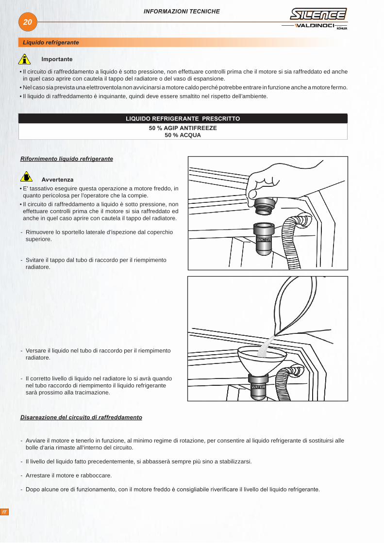
Rifornimento liquido refrigerante
Avvertenza• E’ tassativo eseguire questa operazione a motore freddo, in quanto pericolosa per l’operatore che la compie.
• Il circuito di raffreddamento a liquido è sotto pressione, non effettuare controlli prima che il motore si sia raffreddato ed anche in quel caso aprire con cautela il tappo del radiatore.
- Rimuovere lo sportello laterale d’ispezione dal coperchio superiore.
- Svitare il tappo dal tubo di raccordo per il riempimento radiatore.
- Versare il liquido nel tubo di raccordo per il riempimento radiatore.
- Il corretto livello di liquido nel radiatore lo si avrà quando nel tubo raccordo di riempimento il liquido refrigerante sarà prossimo alla tracimazione.
LIQUIDO REFRIGERANTE PRESCRITTO50 % AGIP ANTIFREEZE
50 % ACQUA
Disareazione del circuito di raffreddamento
- Avviare il motore e tenerlo in funzione, al minimo regime di rotazione, per consentire al liquido refrigerante di sostituirsi alle bolle d‘aria rimaste all‘interno del circuito.
- Il livello del liquido fatto precedentemente, si abbasserà sempre più sino a stabilizzarsi.
- Arrestare il motore e rabboccare.
- Dopo alcune ore di funzionamento, con il motore freddo è consigliabile riverificare il livello del liquido refrigerante.
IT
21
x 1000
IT
INFORMAZIONI TECNICHE
Descrizione delle spie
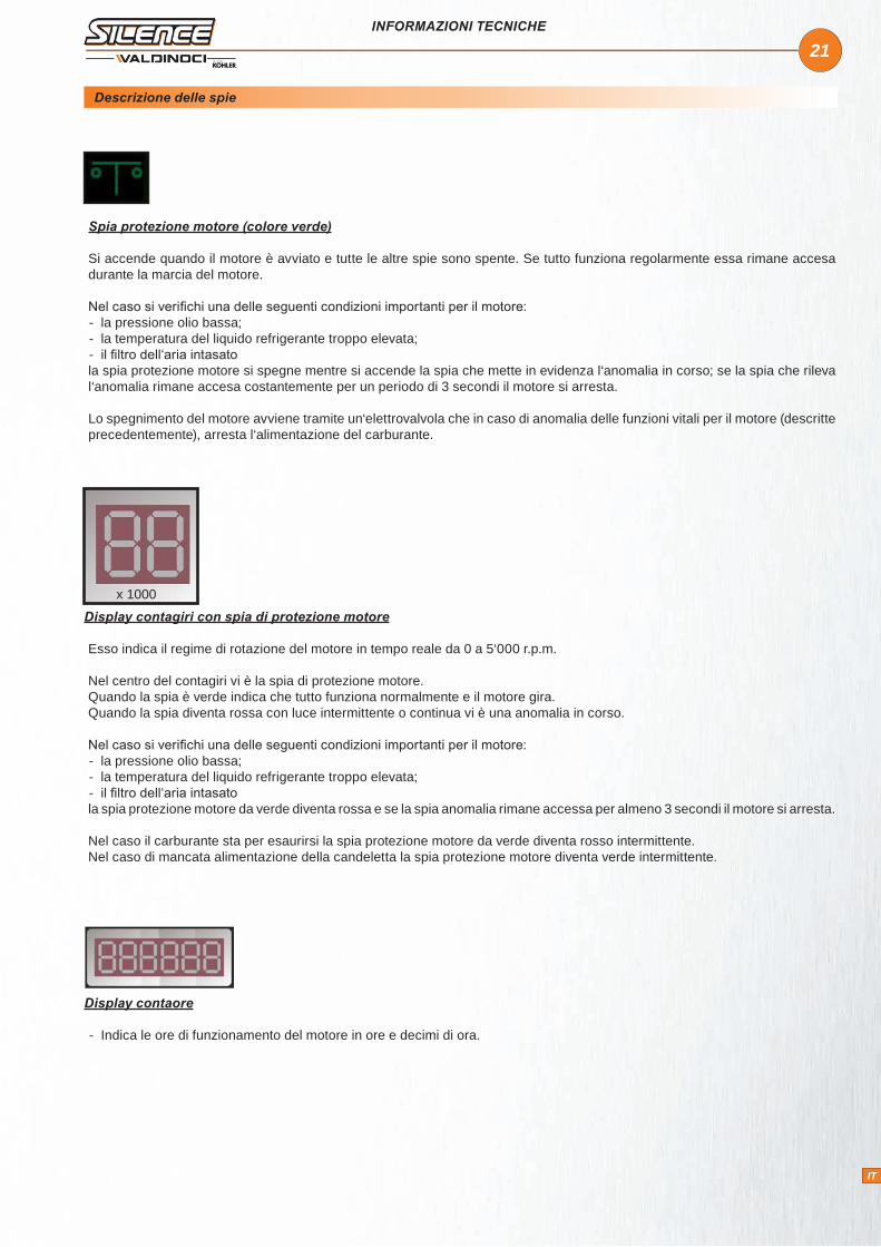
Spia protezione motore (colore verde)
Si accende quando il motore è avviato e tutte le altre spie sono spente. Se tutto funziona regolarmente essa rimane accesa durante la marcia del motore.
Nel caso si verifichi una delle seguenti condizioni importanti per il motore: - la pressione olio bassa; - la temperatura del liquido refrigerante troppo elevata; - il filtro dell‘aria intasato
la spia protezione motore si spegne mentre si accende la spia che mette in evidenza l‘anomalia in corso; se la spia che rileva l‘anomalia rimane accesa costantemente per un periodo di 3 secondi il motore si arresta.
Lo spegnimento del motore avviene tramite un‘elettrovalvola che in caso di anomalia delle funzioni vitali per il motore (descritte precedentemente), arresta l‘alimentazione del carburante.
Display contagiri con spia di protezione motore
Esso indica il regime di rotazione del motore in tempo reale da 0 a 5‘000 r.p.m.
Nel centro del contagiri vi è la spia di protezione motore. Quando la spia è verde indica che tutto funziona normalmente e il motore gira.Quando la spia diventa rossa con luce intermittente o continua vi è una anomalia in corso.
Nel caso si verifichi una delle seguenti condizioni importanti per il motore: - la pressione olio bassa; - la temperatura del liquido refrigerante troppo elevata; - il filtro dell‘aria intasato
la spia protezione motore da verde diventa rossa e se la spia anomalia rimane accessa per almeno 3 secondi il motore si arresta.
Nel caso il carburante sta per esaurirsi la spia protezione motore da verde diventa rosso intermittente.Nel caso di mancata alimentazione della candeletta la spia protezione motore diventa verde intermittente.
Display contaore
- Indica le ore di funzionamento del motore in ore e decimi di ora.
IT

22
IT
INFORMAZIONI TECNICHE
Spia pressione olio (colore rosso)
- Si accende in caso di insufficiente pressione olio. L‘arresto del motore avviene dopo che la spia rimane accesa in modo costante per 3 secondi.
- L'installatore della quasi-macchina può utilizzare questa spia a sua discrezione. Dovrà dettagliare sul manuale della macchina finale il significato di tale spia.
Spia ricarica batteria (colore giallo)
- Si accende in caso di mancata ricarica batteria. L‘arresto del motore avviene dopo che la spia rimane accesa in modo costante per 3 secondi.
Spia candelette (colore giallo)
- Rimane accesa durante il preriscaldo (il tempo di preriscaldo varia con la temperatura ambiente; più lungo nei periodi freddi e più corto in quelli caldi).
- Nei quadretti senza contagiri la spia candelette funziona ad intermittenza quando manca l'alimentazione alle candelette (fusibile bruciato o relè in avaria)
- Nei quadretti con contagiri la spia protezione motore durante il preriscaldo diventa verde quando manca l‘alimentazione alle candelette (fusibile bruciato o relè in avaria).
Spia sovratemperatura olio o testa motore (colore rosso)
- Essa si accende quando la temperatura del liquido refrigerante va oltre la soglia di sicurezza. L‘arresto del motore avviene dopo che la spia rimane accesa in modo costante per 3 secondi.
Spia intasamento filtro aria
- Si accende in caso di intasamento filtro aria.
- L'installatore della quasi-macchina può utilizzare questa spia a sua discrezione. Dovrà dettagliare sul manuale della macchina finale il significato di tale spia.
Spia carburante
- Quando accesa segnala "riserva carburante"
IT

23
- +
IT
AVVIAMENTO/ARRESTO
Avviamento
TEMPERATURA AMBIENTE ESTERNO TEMPO
≤ - 20° C 5’
- 15° C / - 10° C 2’
- 10° C - 5° C 1’
≥ 5° C 20”
Avvertenza
• Assicurarsi che con il motore in marcia tutte le spie di controllo siano spente.
• Per motori equipaggiati con quadro avviamento dotato di protezione motore assicurarsi che rimanga accesa la sola spia "protezione motore (colore verde)".
• Azionare il motorino di avviamento per non più di 20 secondi consecutivi: se il motore non parte attendere un minuto prima di ripetere la manovra di avviamento. Nel caso in cui il motore non parta dopo due tentativi di avviamento conviene consultare la tabella a pag.33 onde individuare la causa dell’inconveniente.
1. Inserire la chiave nel commutatore di avviamento; 1° Scatto in senso orario - Accensione spie.
2. Attendere lo spegnimento della spia "preriscaldo candelette" e ruotare ulteriormente la chiave in senso orario per avviare il motore.
3. Tenere il motore al minimo per qualche minuto come da tabella.
4. Con il motore avviato per aumentare o diminuire il regime di rotazione agire sull’apposito pulsante (posizionato sopra il quadro avviamento), come indicato dalla freccia nella fotografia a fianco.
5. Per aumentare il numero di giri di rotazione premere il pulsante nella parte DESTRA.
6. Per diminuire il numero di giri di rotazione premere il pulsante nella parte SINISTRA.
Avvertenza• Ad avviamento eseguito assicurarsi che non ci siano anomalie motore segnalate dalle spie. In caso contrario, valutare se è necessario arrestare immediatamente il motore o se è possibile continuare le operazioni e procedere all'intervento di ripristino in seguito.
IT

24
IT
AVVIAMENTO/ARRESTO
Arresto
Rodaggio
Prima dell'arresto
- Portare il regime dei giri al minimo per qualche minuto.
Arresto
- Ruotare la chiave in senso antiorario - Rimuovere la chiave
- Nelle prime 50 ore non superare il 70% del carico totale.
Importante
• Le operazioni di manutenzione vanno effettuate a motore freddo.• Utilizzare solo ricambi originali. L'uso di particolari non originali potrebbe causare prestazioni non corrette e scarsa longevità.• Il mancato rispetto delle operazioni descritte nelle pagine seguenti possono comportare il rischio di danni tecnici alla macchina e/o all’impianto.
• L’inosservanza provoca la decadenza della garanzia.
Manutenzione
Dopo le prime 50 ore:
1. Sostituzione olio motore.2. Sostituzione filtro olio motore.
Ogni 10 ore:
1. Controllo livello olio con l’apposita asta:
- Rimuovere lo sportello laterale d’ispezione dal cofano superiore.
- Se il livello olio è prossimo al riferimento di minimo, rabboccare.
- Dopo aver riverificato il livello reinserire l’asta livello olio.
IT

25
IT
MANUTENZIONE
2. Controllo filtro aria a secco:
- Per controllo o sostituzione filtro aria rimuovere lo sportello d’ispezione laterale.
- Smontare il coperchio del filtro agendo sugli appositi ganci.
- Verificare lo stato della massa filtrante ed operare di conseguenza: pulire o sostituire.
- Battere l’elemento su una superficie dura, leggermente e ripetutamente, in modo da eliminare la sporcizia in eccesso.
- Pulire accuratamente il coperchio e il supporto filtro.
Avvertenza
• Nel caso venga usata aria compressa è importante utilizzare occhiali protettivi.
• Utilizzare solo ricambi originali.
- Accertarsi che il filtro aria sia montato in modo corretto altrimenti polvere ed altre impurità possono entrare nei condotti di aspirazione.
- Se la massa filtrante è stata pulita altre volte, o se è irrimediabilmente intasata sostituirla.
- Rimontare massa filtrante e filtro aria.
- Per motori con filtro aria a secco e indicatore di intasamento: se l’indicatore segnala l’intasamento della massa filtrante, procedere alla pulizia o alla sostituzione come dalle indicazioni precedenti.
- Rimuovere lo sportello d’ispezione laterale dal coperchio superiore per accedere al filtro aria.
- Battere delicatamente il filtro per eliminare i residui. Per non danneggiare il filtro di carta, non lavarlo e non pulirlo con aria compressa.
- Se la massa filtrante è stata pulita altre volte, o se è irrimediabilmente intasata gettarla e sostituirla.
- Pulire e rimontare il filtro aria.
Avvertenza
• Utilizzare solo ricambi originali.
2
4
1
3
5
6
1. Bocchettone aria pulita(all’entrata aspirazione)2. Presa aria dall’ambiente3. Corpo filtro aria4. Cartuccia filtrante5. Coperchio inferiore corpo filtro aria6. Valvola scarico polvere
IT

26
MAX
.M
IN.
IT
MANUTENZIONE
3. Controllo livello liquido di raffreddamento
1. Svitare il tappo dal tubo raccordo per il liquido refrigerante
2. Controllare che il liquido sia visibile. Se così non fosse rabboccare fino a renderlo tale.
Avvertenza
• E’ tassativo eseguire questa operazione a motore freddo, in quanto pericolosa per l’operatore che la compie.
• Il circuito di raffreddamento a liquido è sotto pressione, non effettuare controlli prima che il motore si sia raffreddato ed anche in quel caso aprire con cautela il tappo del radiatore.
Ogni 300 ore o 1 anno:
1. Sostituzione olio motore:
Avvertenza
• Per ottenere il rapido e completo scarico dell’olio motore, si consiglia di eseguire tale operazione a motore caldo.
• L’olio motore esausto può essere causa di cancro alla pelle se lasciato ripetutamente a contatto e per periodi prolungati. Se il contatto con l’olio fosse inevitabile, si consiglia di lavarsi accuratamente le mani con acqua e sapone non appena possibile.
• Non disperdere l’olio esausto nell'ambiente in quanto altamente inquinante.
- Azionare la pompa (vedere immagine a fianco) al fine di scaricare l'olio motore esausto.
- Togliere il tappo rifornimento olio.
- Versare l’olio lentamente per evitare il rigurgito, alla fine del rifornimento reinserire il tappo nel proprio alloggiamento.
- Controllare che il livello dell’olio sia al massimo, con il motore in piano.
Avvertenza• Prima del riavvio accertarsi che l‘asta livello, il tappo scarico olio e il tappo rifornimento olio siano montati in modo corretto onde evitare fuoriuscite di lubrificante.
2. Controllo tensione cinghia alternatore:
Importante
• Rivolgersi alle officine autorizzate.IT
27
IT
MANUTENZIONE
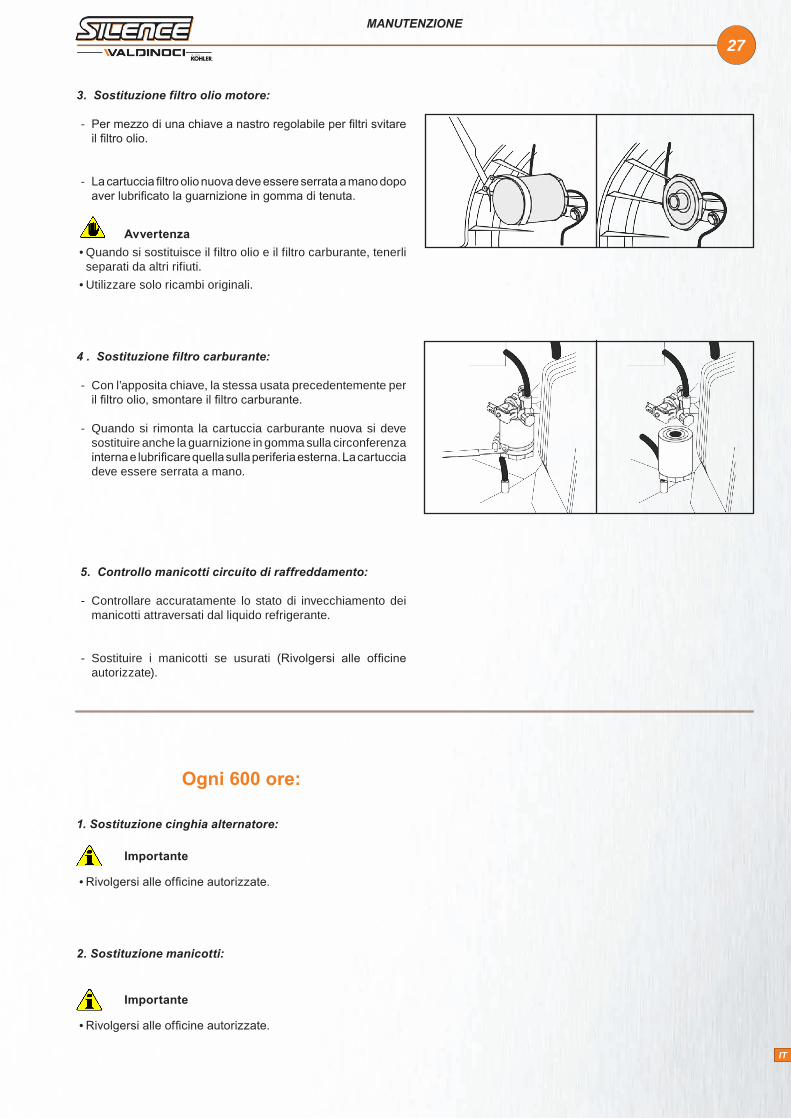
3. Sostituzione filtro olio motore:
- Per mezzo di una chiave a nastro regolabile per filtri svitare il filtro olio.
- La cartuccia filtro olio nuova deve essere serrata a mano dopo aver lubrificato la guarnizione in gomma di tenuta.
Avvertenza• Quando si sostituisce il filtro olio e il filtro carburante, tenerli separati da altri rifiuti.
• Utilizzare solo ricambi originali.
4 . Sostituzione filtro carburante:
- Con l’apposita chiave, la stessa usata precedentemente per il filtro olio, smontare il filtro carburante.
- Quando si rimonta la cartuccia carburante nuova si deve sostituire anche la guarnizione in gomma sulla circonferenza interna e lubrificare quella sulla periferia esterna. La cartuccia deve essere serrata a mano.
5. Controllo manicotti circuito di raffreddamento:
- Controllare accuratamente lo stato di invecchiamento dei manicotti attraversati dal liquido refrigerante.
- Sostituire i manicotti se usurati (Rivolgersi alle officine autorizzate).
Ogni 600 ore:
1. Sostituzione cinghia alternatore:
Importante
• Rivolgersi alle officine autorizzate.
2. Sostituzione manicotti:
Importante
• Rivolgersi alle officine autorizzate.
IT

28
IT
MANUTENZIONE
3. Controllo efficienza del radiatore:
- Se il pacco radiante fosse intasato pulire con pennello e gasolio.
- Soffiare con un getto d’aria compressa.
........................................................................................................................................................
........................................................................................................................................................
........................................................................................................................................................
........................................................................................................................................................
........................................................................................................................................................
........................................................................................................................................................
........................................................................................................................................................
........................................................................................................................................................
........................................................................................................................................................
........................................................................................................................................................
........................................................................................................................................................
........................................................................................................................................................
........................................................................................................................................................
........................................................................................................................................................
........................................................................................................................................................
........................................................................................................................................................
........................................................................................................................................................
........................................................................................................................................................
NOTE
IT

29
IT
Ogni 1200 ore o 2 anni:
1. Sostituzione liquido di raffreddamento:
Pericolo
• Il circuito di raffreddamento a liquido è sotto pressione, non effettuare controlli prima che il motore si sia raffreddato ed anche in quel caso aprire con cautela il tappo del radiatore.
• Il liquido di raffreddamento è inquinante quindi deve essere smaltito nel rispetto dell’ambiente.
- Rimuovere lo sportello d’ispezione del cofano superiore.
- Svitare il tappo per togliere pressione all’interno del circuito di raffreddamento.
- Aprire l’apposito rubinetto che permette lo scarico del liquido refrigerante, situato sulla parte inferiore del radiatore.
- Fissare un tubo flessibile in gomma di Ø compatibile con l’apposita connessione, per recuperare il liquido refrigerante in un recipiente.
- Terminato lo scarico del liquido refrigerante, richiudere il rubinetto.
- Versare e ripristinare il livello del liquido refrigerante nel circuito.
- Ripetere l’operazione di disareazione del circuito di raffreddamento, vedi pag. 20.
MANUTENZIONE
IT
30
IT
Importante
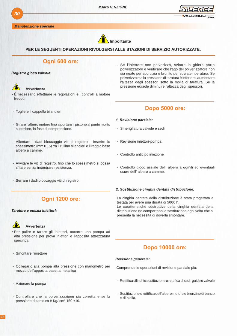
PER LE SEGUENTI OPERAZIONI RIVOLGERSI ALLE STAZIONI DI SERVIZIO AUTORIZZATE.
MANUTENZIONE
Ogni 600 ore:
Registro gioco valvole:
Avvertenza• É necessario effettuare le regolazioni e i controlli a motore freddo.
- Togliere il cappello bilancieri
- Girare l’albero motore fino a portare il pistone al punto morto superiore, in fase di compressione.
- Allentare i dadi bloccaggio viti di registro - Inserire lo spessimetro (mm 0.15) tra il rullino bilancieri e il raggio base albero a camme.
- Avvitare le viti di registro, fino che lo spessimetro si possa sfilare senza incontrare resistenza.
- Serrare i dadi bloccaggio viti di registro.
Ogni 1200 ore:
Taratura e pulizia iniettorI:
Avvertenza• Per pulire e tarare gli iniettori, occorre una pompa ad alta pressione per prova iniettori e l’apposita attrezzatura specifica.
- Smontare l’iniettore
- Collegarlo alla pompa alta pressione con manometro per mezzo dell’apposita basetta metallica
- Azionare la pompa
- Controllare che la polverizzazione sia corretta e se la pressione di taratura è Kg/ cm² 150 ±10.
Dopo 10000 ore:
Revisione generale:
Comprende le operazioni di revisione parziale più:
- Rettifica cilindri e sostituzione o rettifica di sedi, guide e valvole
- Sostituzione o rettifica dell’albero motore e bronzine di banco e di biella.
Dopo 5000 ore:
1. Revisione parziale:
- Smerigliatura valvole e sedi
- Revisione iniettori-pompa
- Controllo anticipo iniezione
- Controllo gioco assiale dell’ albero a gomiti ed eventuali usure dell’ albero a camme.
2. Sostituzione cinghia dentata distribuzione:
La cinghia dentata della distribuzione è stata progettata e testata per avere una durata di 5000 h. Le caratteristiche costruttive della cinghia dentata della distribuzione ne comportano la sostituzione ogni volta che si presenta la necessità di doverla smontare.
- Se l’iniettore non polverizza, svitare la ghiera porta polverizzatore e verificare che l’ago del polverizzatore non sia rigato per sporcizia o brunito per sovratemperatura. Se polverizza ma la pressione di taratura è inferiore, aumentare l’altezza degli spessori sotto la molla di taratura. Se la pressione eccede diminuire l’altezza degli spessori.
Manutenzione speciale
IT

31
IT
IMMAGAZZINAGGIO
Importante
QUANDO I MOTORI RIMANGONO INUTILIZZATI PER OLTRE 3 MESI, DEVONO ESSERE PROTETTI, ATTUANDO LE OPERAZIONI DESCRITTE NELLE PAGINE SEGUENTI.
Immagazzinaggio
Stoccaggio motore (non installato)
Trattamento protettivo
- In caso di prevista inattività prolungata del Silence, verificare le condizioni dell’ambiente, il tipo di imballaggio e controllare che tali condizioni ne assicurino un corretto mantenimento.
- Se necessario coprire il Silence con un adeguato telo protettivo.
- Evitare lo stoccaggio del Silence a diretto contatto con il suolo, in ambienti umidi ed esposti ad intemperie, in prossimità di fonti di pericolo e anche quelle meno visibili (linee elettriche ad alta tensione, ecc.).
Avvertenza• Se l’inattività prevista del Silence è superiore a 1 mese, è necessario effettuare un trattamento protettivo valido per 6 mesi (vedi “Trattamento protettivo”).
Importante
• Se il Silence, trascorsi i primi 6 mesi, non viene utilizzato, è necessario effettuare un ulteriore intervento per estendere il periodo di stoccaggio (vedi “Trattamento protettivo”).
1 - Controllare che l’olio motore e il liquido di raffreddamento siano a livello.
2 - Effettuare il riempimento carburante additivandolo con il 10 % di AGIP RUSTIA NT.
3 - Accendere il motore e mantenerlo al regime minimo, a vuoto, per 15 minuti.
4 - Spegnere il motore.
5 - Togliere l’olio di lubrificazione.
6 - Riempire il carter con olio protettivo AGIP RUSTIA.
7 - Accendere il motore e verificare eventuali perdite di carburante e di olio.
8 - Portare il motore a 3/4 del massimo regime per 5÷10 minuti.
9 - Spegnere il motore.
10 - Svuotare completamente il serbatoio carburante.
11 - Sostituire il filtro carburante.
12 - Spruzzare olio SAE 10W nei collettori di scarico e di aspirazione.
13 - Chiudere tutte le aperture per evitare l’introduzione di corpi estranei.
14 - Pulire accuratamente, con prodotti adeguati, tutte le parti esterne del motore.
15 - Trattare le parti non verniciate con prodotti protettivi (AGIP RUSTIA 100/F).
16 - Allentare la cinghia alternatore/ventilatore.
17 - Se necessario, coprire il motore con un adeguato telo protettivo.
Avvertenza • Nei paesi in cui i prodotti AGIP non sono commercializzati, reperirne sul mercato uno equivalente.
Importante
• Al raggiungimento di un anno di inattività del motore,il liquido di raffreddamento perde le sue proprietà ed è necessario sostituirlo.
IT

32
IT
Messa in servizio motore dopo il trattamento protettivo
IMMAGAZZINAGGIO
Dopo un periodo di inattività, prima di installare il motore e metterlo in servizio, è necessario effettuare alcuni interventi per garantire condizioni di massima efficienza.
1 - Togliere il telo protettivo.2 - Togliere le eventuali otturazioni dai condotti di aspirazione e di scarico.3 - Utilizzare un panno imbevuto di prodotto sgrassante per rimuovere il trattamento protettivo esterno.4 - Rimuovere il collettore di aspirazione.5 - Iniettare olio lubrificante (non oltre 2 cm3) nelle valvole ed installare il collettore di aspirazione.6 - Regolare la tensione della cinghia alternatore/ventilatore.7 - Girare manualmente il volano per verificare la corretta movimentazione degli organi meccanici.8 - Rifornire il serbatoio con del carburante nuovo.9 - Accendere il motore e portarlo a 3/4 del massimo regime per 5-10 minuti.10 - Spegnere il motore.11 - Togliere l’olio protettivo per sostituirlo con l’olio motore.12 - Introdurre l’olio nuovo (vedi “Lubrificanti”) fino a raggiungere il livello corretto segnalato sull’asta.13 - Sostituire i filtri (aria, olio, carburante) con ricambi originali.14 - Svuotare completamente il circuito di raffreddamento e introdurre il liquido di raffreddamento nuovo fino al livello corretto.
Avvertenza • Alcuni componenti del motore e i lubrificanti, anche in caso di inattività, nel tempo perdono le loro proprietà, è quindi necessario considerare la loro sostituzione non solo in base alle "ore di lavoro", ma anche per l’invecchiamento da stress.
15 - Effettuare l’installazione del motore sulla macchina ed eseguire i collegamenti ed allacciamenti necessari.16 - Controllare l’integrità e l’efficienza dei contatti elettrici.17 - Controllare che l’olio motore e il liquido di raffreddamento siano a livello.18 - Accendere il motore e mantenerlo al regime minimo per qualche minuto.19 - Verificare eventuali perdite di liquidi e, se necessario, individuare il difetto ed eliminare l’anomalia.20 - Spegnere il motore.21 - Ricontrollare che l’olio motore e il liquido di raffreddamento siano a livello.
........................................................................................................................................................
........................................................................................................................................................
........................................................................................................................................................
........................................................................................................................................................
........................................................................................................................................................
........................................................................................................................................................
........................................................................................................................................................
........................................................................................................................................................
........................................................................................................................................................
NOTE
IT

33
IT
Tabelle probabili anomalie in funzione dei sintomi
ANOMALIE
Importante
QUANDO IL MOTORE DEVE ESSERE IMMEDIATAMENTE ARRESTATO
1) - I giri del motore aumentano e diminuiscono improvvisamente
2) - Viene udito un rumore inusuale e improvviso
3) - Il colore dei gas di scarico diventa improvvisamente scuro
4) - La spia di controllo pressione olio, si accende durante la marcia
INCONVENIENTI
CAUSA PROBABILE N
on p
arte
Par
te e
si f
erm
a
Non
acc
eler
a
Reg
ime
inco
stan
te
Fum
o ne
ro
Fum
o bi
anco
Pre
ssio
ne o
lio
bass
a
MA
NU
TEN
ZIO
NE Filtro aria intasato
Funzionamento prolungato al minimo
Rodaggio incompleto
Sovraccarico
REG
ISTR
AZI
ON
E / R
IPA
RA
ZIO
NE
Anticipo iniezione incorretto
Leveraggi regolatore fuori fase
Molla regolatore rotta
Minimo basso
Segmenti usurati o incollati
Cilindro usurato
Valvole bloccate
Bronzine banco-biella usurate
Dadi fissaggio testa allentati
CIR
CU
ITO
CA
RB
UR
AN
TE
Tubazioni ostruite
Filtro carburante intasato
Aria nel circuito carburante
Foro disaereazione serbatoio otturato
Iniettore bloccato
IT

34
IT
CAUSA PROBABILE
INCONVENIENTI
Non
par
te
Par
te e
si f
erm
a
Non
acc
eler
a
Reg
ime
inco
stan
te
Fum
o ne
ro
Fum
o bi
anco
Pre
ssio
ne o
lio
bass
a
CIR
CU
ITO
C
AR
BU
RA
NTE
Valvola pompa iniezione bloccata
Iniettore non registrato
Pompa alimentazione difettosa
Asta cremagliera indurita
Supplemento carburante bloccato
LUB
RIF
ICA
ZIO
NE
Livello olio alto
Valvola regolazione pressione bloccata
Valvola regolazione non registrata
Pompa olio usurata
Aria nell’aspirazione olio
Manometro o pressostato difettoso
Tubo aspirazione olio ostruito
IMPI
AN
TO E
LETT
RIC
O
Batteria scarica
Collegamento cavi incerto o errato
Interruttore avviamento difettoso
Motorino avviamento difettoso
ANOMALIE
........................................................................................................................................................
........................................................................................................................................................
........................................................................................................................................................
........................................................................................................................................................
........................................................................................................................................................
........................................................................................................................................................
........................................................................................................................................................
........................................................................................................................................................
........................................................................................................................................................
NOTE
IT


36
EN
MANUFACTURER AND PARTLY COMPLETED MACHINERY IDENTIFICATION ............................................1
CONTENT SUMMARY OF MAINTENANCE OPERATIONS. ......................................................................37
GENERAL INFORMATION ...................................................37
Preface..................................................................................37
SAFETY INFORMATION ......................................................39
Permitted usage and improper use ...................................39
Safety warnings ...................................................................39
Graphic symbols .................................................................40
Safety and environmental impact ......................................41
Location of safety signs on the engine .............................41
TECHNICAL FEATURES ......................................................43
Dimensions ..........................................................................43
BEFORE STARTING ............................................................46
HANDLING ............................................................................46
DISASSEMBLY CANOPY UPPER PART SILENCE ............47
CIRCUITS ..............................................................................48
Batteries ...............................................................................48
Electrical system .................................................................49
TECHNICAL INFORMATION ................................................50
Oil ..........................................................................................50
Fuel .......................................................................................52
Coolant .................................................................................54
Indicators description .........................................................55
STARTING/STOPPING .........................................................57
Starting .................................................................................57
Run-in ...................................................................................58
Stopping ...............................................................................58
MAINTENANCE ....................................................................58
Maintenance (After the first 50 working hours) ...............58
Maintenance (Every 10 hours) ...........................................59
Maintenance (Every 300 hours or 1 year) .........................60
Maintenance (Every 600 hours) .........................................61
Maintenance (Every 1200 hours or 2 years) .....................63
Special maintenance (Every 600 hours) ............................64
Special maintenance (Every 1200 hours) ..........................64
Special maintenance (After 5000 hours) ...........................64
Special maintenance (After 10000 hours) .........................64
STORAGE .............................................................................65
Storage .................................................................................65
Engine storage (not installed) ............................................65
Protective treatment ............................................................65
Preparing the engine for operation after protective treatment ..............................................................................66
ANOMALIES .........................................................................67
Table of likely anomalies and their symptoms .................67

37
EN
SUMMARY OF RUNNING IN MAINTENANCEOPERATION DESCRIPTION
AFTER THE FIRST 50 WORKING HOURSPAG.
Engine oil replacement 60Oil filter replacement 61
CHECK
OPERATION DESCRIPTIONFREQUENCY X HOURS
PAG.10 300 600 1200 5000
Oil level 58Air cleaner (***) 59Coolant level 60Alternator belt stretch control (*) 60Cooling circuit sleeves (*) 61Radiator efficiency check @ 62
Valve clearance adjustment @ 64
Setting and injectors cleaning 64
(*) - In case of low use: every year. (**) - In case of low use: every 2 years
(***) - The period of time that must elapse before cleaning or replacing the filter element depends on the environment in which the engine operates. The air filter must be cleaned and replaced more frequently in very dusty conditions. @ Maintenance to be carried out at the service stations
REPLACEMENT
OPERATION DESCRIPTIONFREQUENCY X HOURS
PAG.125 300 600 1200 5000
Oil engine (*) 60Oil filter (*) 61Fuel filter replacement (*) 61
Alternator belt replacement 61Cooling circuit sleeves replacement 61Coolant replacement (*)@ 63
Timing belt replacement 64
OVERHAUL
OPERATION DESCRIPTIONFREQUENCY X HOURS
PAG.300 600 1200 5000 10000
Partial overhaul @ 64
Total overhaul @ 64
SUMMARY OF FIRST MAINTENANCE OPERATIONS.
ORDINARY MAINTENANCE
Content summary of maintenance operations
The preventive maintenance intervals reported herein apply to an engine operating in normal operating conditions, with fuel and oil conform to the technical characteristics indicated in this manual.

38
EN
Preface
Every attempt has been made to present within this service manual accurate and up to date technical information. However, development on the series is continuos. Therefore, the information within this manual is subject to change without notice and without obligation.The information contained within this service manual is the sole property of Valdinoci Luigi S.p.A . As such, no reproduction or replication in whole or part is allowed without the express written permission of Valdinoci Luigi S.p.A .Information presented within this manual assumes the following:1 - The person or persons performing service work on engines is properly trained and equipped to safely and professionally perform the subject operation;2 - The person or persons performing service work on engines possesses adequate hand and special tools to safely and professionally perform the subject service operation;3 - The person or persons performing service work on engines has read the pertinent information regarding the subject service operations and fully understands the operation at hand.
General service manual notes:
1- Use only genuine repair parts. Failure to use genuine parts could result in sub-standard performance and low longevity.
2- All data presented are in metric format. That is, dimensions are presented in millimeters (mm), torque is presented in Newton-meters (Nm), weight is presented in kilograms (Kg), volume is presented in liters or cubic centimeters (cc) and pressure is presented in barometric units (bar).
Warranty certificate
The products manufactured by Valdinoci Luigi S.p.A Srl are warranted to be free from conformity defects for a period of 24 months from the date of delivery to the first end user.For engines fitted to stationary equipment, working at constant load and at constant and/or slightly variable speed within the setting limits, the warranty covers a period up to a limit of 2000 working hours, if the above mentioned period (24 months) is not expired.If no hour-meter is fitted , 12 working hours per calendar day will be considered.For what concerns the parts subject to wear and deterioration (injection/feeding system, electrical system, cooling system, sealing parts, non-metallic pipes, belts) warranty covers a maximum limit of 2000 working hours, if the above mentioned period (24 months) is not expired.For correct maintenance and replacement of these parts, it is necessary to follow the instructions reported in the documentation supplied with each engine.To ensure the engine warranty is valid, the engine installation, considering the product technical features, must be carried out by qualified personnel only.Special applications involving considerable modifications to the cooling/lubricating system (for ex.: dry oil sump), filtering system, turbo-charged models, will require special written warranty agreements.Within the above stated periods Valdinoci Luigi S.p.A directly or through its authorized network will repair and/or replace free of charge any own part or component that, upon examination by Valdinoci Luigi S.p.A or by an authorized Valdinoci Luigi S.p.A agent, is found to be defective in conformity, workmanship or materials.Any other responsibility/obligation for different expenses, damages and direct/indirect losses deriving from the engine use or from both the total or partial impossibility of use, is excluded.The repair or replacement of any component will not extend or renew the warranty period. Valdinoci Luigi S.p.A warranty obligations here above described will be cancelled if:- engines are not correctly installed and as a consequence the correct functional parameters are not respected and altered.- engines are not used according to the instructions reported in the “Use and Maintenance” booklet supplied with each engine.- Any seal affixed to the engine by Valdinoci Luigi S.p.A has been tampered with or removed.- Spare parts used are not original.- Feeding and injection systems are damaged by unauthorized or poor quality fuel types.- Electrical system failure is due to components, connected to this system, which are not supplied or installed by Valdinoci Luigi S.p.A .- Engines have been disassembled, repaired or altered by any part other than an authorized agent.
Following expiration of the above stated warranty periods and working hours, Valdinoci Luigi S.p.A will have no further responsibility for warranty and will consider its here above mentioned obligations for warranty complete.Any warranty request related to a non-conformity of the product must be addressed to the Valdinoci Luigi S.p.A service agents.
GENERAL INFORMATION

39
EN
Safety warnings
Permitted usage and improper use
SAFETY INFORMATION
• Those who carry out the use and maintenance on the engine must wear the safety equipment and the accident-prevention guards.
• Valdinoci Luigi S.p.A declines all direct and indirect liability for failure to comply with the standards of conduct contained in this manual.
• Valdinoci Luigi S.p.A cannot consider every reasonably unforeseeable misuse that may cause a potential danger.
• The intended use of the engine is in conformity with the machine on which it is mounted.
• Any use of the machine other than that described cannot be considered as complying with its intended purpose as specified by Valdinoci Luigi S.p.A .
• Valdinoci Luigi S.p.A declines all responsibility for any change to the engine not described in this manual made by unauthorized Valdinoci Luigi S.p.A personnel.
• A proper use of the engine, a strict observance of the rules listed below and the rigorous application of all these precautions will avoid the risk of accidents or injuries.
• The engine has been built to the specifications of a machine manufacturer, and it is his responsibility to ensure that all necessary action is taken to meet the essential and legally prescribed health and safety requirements. Any use of the machine other than that described cannot be considered as complying with its intended purpose as specified by Valdinoci Luigi S.p.A, which therefore declines all responsibility for accidents caused by such operations.
• The following guidelines are for technical installers and must be incorporated into the new technical documentation specifically designed for the assembly: MACHINE + PARTLY COMPLETED MACHINERY (endothermic engine unit).
It is the task of those who incorporate the P.C.M. to check:• power management;• the safety requirements before, during and after the stop phase
The person who incorporates the P.C.M. must make sure that:• The emergency stop immediately stops the moving parts (category 0), by switching off the power.
• The emergency stop overrides all other functions and stops the actuators immediately without creating additional hazards.
• The user must read these instructions carefully. Failure to do this could lead to serious danger for his personal safety and health and that of any persons who may be in the vicinity of the machine.
• On starting, make sure that the engine is as horizontal as possible, unless the machine specifications differ.
• Make sure that the machine is stable to prevent the risk of overturning.
• The engine must not operate in places containing inflammable materials, in explosive atmospheres, where there is dust that can easily catch fire unless specific, adequate and clearly indicated precautions have been taken and have been certified for the machine.
• To prevent fire hazards, always keep the machine at least one meter from buildings or from other machinery.
• Children and animals must be kept at a due distance from operating machines in order to prevent hazards deriving from their operation.
• Thoroughly wash and clean all the external parts of the
engine before performing any operation, in order to avoid the accidental introduction of impurities/foreign bodies. Use only water and/or appropriate products to clean the engine. If cleaning engine with a pressure washer or steam cleaner, it is important to maintain a minimum distance of at least 200mm between the surface to be washed and the nozzle.
• Avoid directing the nozzle on electrical components, cable connections and sealed rings (oil seals etc). Thoroughly wash and clean the area surrounding the engine following the instructions provided by machine manufacturer.
• Fuel and oil are inflammable. The tank must only be filled when the engine is off. Before starting, dry any spilt fuel.
• Make sure that no soundproofing panels and the ground or floor on which the machine is standing have not soaked up any fuel.
• Fuel vapour is highly toxic. Only refuel outdoors or in a well ventilated place.
• Do not smoke or use open flames when refuelling.• During operation, the surface of the engine can become dangerously hot. Avoid touching the exhaust system in particular.
• Before proceeding with any operation on the engine, stop it and allow it to cool.
• Always open the radiator plug or expansion chamber with the utmost caution, wearing protective garments and goggles.
• The coolant fluid is under pressure. Never carry out any inspections until the engine has cooled.
• If there is an electric fan, do not approach the engine when it is still hot as the fan could also start operating when the engine is at a standstill.
• The oil must be drained whilst the engine is hot. Particular care is required to prevent burns. Do not allow oil to come into contact with the skin because of the health hazards involved. It is recommended to use an oil intake pump.
• During operations that involve access to moving parts of the engine and/or removal of rotating guards, disconnect and insulate the negative wire (-) of the battery to prevent accidental short-circuits and to stop the starter motor from being energized.
• Check belt tension only when the engine is off.• Fully tighten the tank cap each time after refuelling. Do not
40
EN
Graphic symbols
SAFETY INFORMATION
• To ensure safe operation please read the following statements and understand their meaning.
• Also refer to your equipment manufacturer's manual for other important safety information.
• This manual contains safety precautions which are explained below.
• Please read them carefully. Danger
• This indicates situations of grave danger which, if ignored, may seriously threaten the health and safety of individuals.
Important
• This indicates particularly important technical information that should not be ignored.
Warning
• This indicates that failure to comply with it can cause minor damage or injury.
Hereunder is a list of safety warnings that may be found in the manual, which advise you to pay attention when carrying out particular procedures that may be potentially dangerous to the operator or things.
fill the tank right to the top but leave an adequate space for the fuel to expand.
• To start the engine follow the specific instructions provided in the engine and/or machine operating manual. Do not use auxiliary starting devices not originally installed on the machine (e.g. Startpilot).
• Before starting, remove any tools that were used to service the engine and/or machine. Make sure that all guards have been refitted.
• Do not mix fuel with elements such as oil or kerosene. Failure to comply with this prohibition will cause the non-operation of the catalyst and non-observance of the emissions declared by Valdinoci Luigi S.p.A.
• Pay attention to the temperature of the oil filter when the filter itself is replaced.
• Only check, top up and change the coolant fluid when the engine is off and reached the ambient temperature. Coolant fluid is polluting, it must therefore be disposed of in the correct way.
• Do not use jets of air and water at high pressure on the cables, connectors and electronic injectors.
• Accidental Starts can cause severe injury or death. Before working on the engine or equipment, disconnect the battery negative (-) wire.
• Hot Parts can cause severe burns. Engine components can get extremely hot from operation. Do not touch engine while operating or just after stopping. Never operate the engine with heat shields or guards removed.
• Rotating Parts can cause severe injury. Stay away while engine is in operation. Keep hands, feet, hair, and clothing away from all moving parts to prevent injury. Never operate the engine with covers, shrouds, or guards removed.
• Carbon Monoxide can cause severe nausea, fainting or death. Avoid inhaling exhaust fumes and never run the engine in a closed building or confined area. Carbon monoxide is toxic, odorless, colorless, and can cause death if inhaled.
• High Pressure Fluids can puncture skin and cause severe injury or death. Work on the injection system must be carried out by suitably trained staff wearing protection equipment. Injuries caused by fluid penetration are highly toxic and dangerous. If an injury occurs, seek immediate medical attention.
• Explosive fuel can cause fires and severe burns. Fuel is flammable and its vapours can ignite. Store fuel only in approved containers, in well ventilated, unoccupied buildings. Do not fill the fuel tank while the engine is hot or running, since spilled fuel could ignite if it comes in contact with hot parts or sparks from ignition. Do not start the engine near spilled fuel. Never use fuel as a cleaning agent.
• Explosive Gas can cause fires and severe acid burns. Charge battery only in a well ventilated area. Keep sparks, open flames, and other sources of ignition away from the battery at all times. Batteries produce explosive hydrogen gas while being charged. Keep batteries out of the reach of children. Remove all jewelry when servicing batteries. Before disconnecting the negative (-) ground cable, make sure all switches are OFF. If ON, a spark could occur at the ground cable terminal which could cause an explosion.
• Electrical Shock can cause injury. Do not touch wires while engine is running.
• Engine exhaust from this product contains chemicals known to the State of California to cause cancer, birth defects, or other reproductive harm.

41
EN
SAFETY INFORMATION
Safety and environmental impact
Every organisation has a duty to implement procedures to identify, assess and monitor the influence of its own activities (products, services, etc.) on the environment.Procedures for identifying the extent of the impact on the environment must consider the following factors:
- Disposal of liquids. - Waste management. - Soil contamination. - Atmospheric emissions. - Use of raw materials and natural resources. - Regulations and directives regarding environmental impact.
In order to minimise the impact on the environment, Valdinoci Luigi S.p.A provides some indications to be followed by all those handling the engine, for any reason, during its expected lifetime.
- All components and fluids must be disposed of in accordance with the laws of the country in which disposal is taking place.
- Keep the injection system as well as engine management and exhaust pipes in efficient working in order to limit environmental and noise pollution.
- When decommissioning the engine, select all components according to their chemical characteristics and dispose of them separately.
Location of safety signs on the engine

42
EN
SAFETY INFORMATION
SIGNAL DESCRIPTION
SAFETY GOGGLES
Indicates that it is mandatory to wear safety goggles before working on the machine.
PROTECTIVE GLOVES
Indicates that it is mandatory to wear protective gloves before working on the machine.
MANDATORY ANCHOR POINT
This plate indicates the anchor and lifting point; any other point is considered unsafe.
GROUND PLATE
Indicates the point where the screw is to be used to earth the frame
FIRE HAZARD
This plate is applied onto the adjacent surfaces of flammable substances (positioned next to the tank).
BURN HAZARD, HOT SURFACES
This plate is applied to surfaces that may become hot and pose a burn hazard during work.
CONSULTATION OF THE USER MANUAL IS MANDATORY
This plate refers to the obligation to consult the instruction manual before working on the machine.
OBLIGATION TO REMOVE KEY DURING MAINTENANCE
PROHIBITION TO REPAIR, GREASE, REGULATE AND CLEAN MOVING PARTS
SMOKING PROHIBITED
Indicates that smoking is prohibited next to the machine.
OPEN FLAMES
Indicates that the use of open flames is prohibited next to the machine.

43
EN
TECHNICAL FEATURES
Engine Type KOHLER KDW 1003 KDW 1404 KDW 1603 KDW 2204Displacement cm3 1028 1372 1649 2204Power (Nb ISO 3046 IFN) kW 18,0 @ 3000 22,5 @ 3000 29,0 @ 3000 36,6 @ 3000Noise level dB (A) 72 72 75 75Weight Kg 260 273 313 341Dimensions cmCm 71 x 90 x 83,5 71 x 90 x 83,5 71 x 90 x 83,5 71 x 90 x 83,5EMISSIONS compliance / 2004/26 CE stage
IIIA2004/26 CE stage
IIIA2004/26 CE stage
IIIA
Technical features
Dimensions
650
173
66
205 205
4x Ø 14
300
360
365

44
EN
CHARACTERISTICS

45
EN
........................................................................................................................................................
........................................................................................................................................................
........................................................................................................................................................
........................................................................................................................................................
........................................................................................................................................................
........................................................................................................................................................
........................................................................................................................................................
........................................................................................................................................................
........................................................................................................................................................
........................................................................................................................................................
........................................................................................................................................................
........................................................................................................................................................
........................................................................................................................................................
........................................................................................................................................................
........................................................................................................................................................
........................................................................................................................................................
........................................................................................................................................................
........................................................................................................................................................
........................................................................................................................................................
........................................................................................................................................................
........................................................................................................................................................
........................................................................................................................................................
........................................................................................................................................................
........................................................................................................................................................
........................................................................................................................................................
........................................................................................................................................................
........................................................................................................................................................
........................................................................................................................................................
........................................................................................................................................................
........................................................................................................................................................
........................................................................................................................................................
NOTES

46
EN
Warning
• Carefully read and follow all instructions in this booklet as well as all those provided with the equipment on which this engine is used.
• FOR THE FIRST 50 RUNNING HOURS, DO NOT USE THE ENGINE WITH MORE THAN 70% OF THE MAXIMUM POWER.
• Failure to do so will make warranty void. • Before starting SILENCE, it is recommended to read the following WARNINGS AND SAFETY INSTRUCTIONS.
BEFORE STARTING
• Check that cooling liquid and motor oil are at the correct level.• Check that the electrical equipment is properly connected.• Make sure that the side inspection doors are locked and blocked by means of the handles provided.
• Check that the four blocking knobs are properly fastened.
Before starting
• To lift or move SILENCE, use the convenience hook only (located on the base, engine panel side) , which is placed on the upper part of the canopy.
Handling
Warning
The eye bolt has been designed to lift only the PARTLY COMPLETED MACHINERY. It is prohibited to use the eye bolt to lift the final machine into which the PARTLY COMPLETED MACHINERY was incorporated.
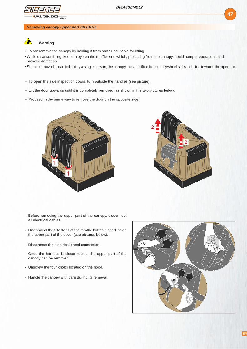
47
EN
DISASSEMBLY
- Before removing the upper part of the canopy, disconnect all electrical cables.
- Disconnect the 3 fastons of the throttle button placed inside the upper part of the cover (see pictures below).
- Disconnect the electrical panel connection.
- Once the harness is disconnected, the upper part of the canopy can be removed.
- Unscrew the four knobs located on the hood.
- Handle the canopy with care during its removal.
Warning
• Do not remove the canopy by holding it from parts unsuitable for lifting.• While disassembling, keep an eye on the muffler end which, projecting from the canopy, could hamper operations and provoke damages.
• Should removal be carried out by a single person, the canopy must be lifted from the flywheel side and tilted towards the operator.
- To open the side inspection doors, turn outside the handles (see picture).
- Lift the door upwards until it is completely removed, as shown in the two pictures below.
- Proceed in the same way to remove the door on the opposite side.
Removing canopy upper part SILENCE
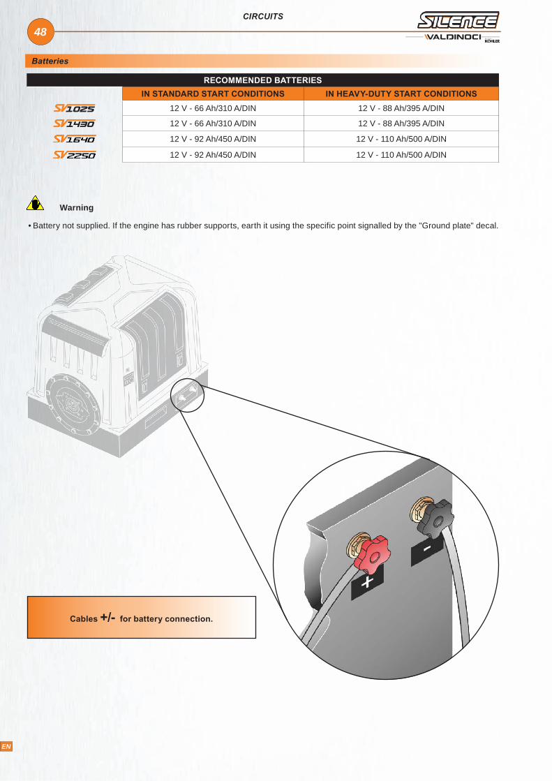
48
EN
CIRCUITS
Cables +/- for battery connection.
Batteries
RECOMMENDED BATTERIESIN STANDARD START CONDITIONS IN HEAVY-DUTY START CONDITIONS
12 V - 66 Ah/310 A/DIN 12 V - 88 Ah/395 A/DIN
12 V - 66 Ah/310 A/DIN 12 V - 88 Ah/395 A/DIN
12 V - 92 Ah/450 A/DIN 12 V - 110 Ah/500 A/DIN
12 V - 92 Ah/450 A/DIN 12 V - 110 Ah/500 A/DIN
Warning
• Battery not supplied. If the engine has rubber supports, earth it using the specific point signalled by the "Ground plate" decal.

49
EN
CIRCUITS
Electrical system
REF. DESCRIPTION
1 Alternator
2 Starter motor
3 Battery
4 Preheating glow plugs
5 Coolant temperature monitoring sensor
6 Glow plug pre-heating control box
7 Ignition switch
8/9 Fuses
10 Electrostop device or electrical fuel lift pump
11 Glow plugs indicator
12 Coolant temperature indicator
13 Coolant thermostat indicator light
14 Engine oil pressure lamp
15 Oil pressure gauge
16 Battery load indicator
17 Diode
18 Air cleaner clogging warning light
19 Clogging gauge
20 Fuel level light
21 Fuel level indicator
A PARKING
B STOP
C RUNNING
D STARTING

50
EN
Oil
TECHNICAL INFORMATION
SAE classification
In the SAE classification, oils differ on the basis of their viscosity, and no other qualitative characteristic is taken into account.The first number refers to the viscosity when the engine is cold (symbol W = winter), while the second considers viscosity with the engine at régime.The criteria for choosing must consider, during winter, the lowest outside temperature to which the engine will be subject and the highest functioning temperature during summer.Single-degree oils are normally used when the running temperature varies scarcely.Multi-degree oil is less sensitive to temperature changes.
Important
• The engine may be damaged if operated with insufficient lube oil. It is also dangerous to supply too much lube oil to the engine because a sudden increase in engine rpm could be caused by its combustion. Use proper lube oil to preserve your engine. Nothing affects the performance and durability of your engine more than the lube oil you use. If inferior oil is used, or if your engine oil is not changed regularly, the risk of piston seizure, piston ring sticking, and accelerated wear of the cylinder liner, bearing and other moving components increases significantly. Always use oil with the right viscosity for the ambient temperature in which your engine is being operated . Use the chart when chosing your engine oil.
• The used engine oil can cause skin-cancer if kept frequently in contact for prolonged periods. If contact with oil cannot be avoided, wash carefully your hands with water and soap as soon as possible. Do not disperse the oil in the environment, as it has a high pollution power.
Lubricant international specifications
They define testing performances and procedures that the lubricants need to successfully respond to in several engine testing and laboratory analysis so as to be considered qualified and in conformity to the regulations set for each lubrication kind.
A.P.I: (American Petroleum Institute) MIL: Engine oil U.S. military specifications released for logistic reasonsACEA: European Automobile Manufacturers AssociationTables shown below are of useful reference when buying a kind of oil.
* SAE 15W-40: mineral base
** SAE 15W-40 / SAE 20W-60: semi-synthetic base
*** SAE 5W-30 / SAE 0W-30: synthetic base
40 10 2035 5 2530 0 3025 5 3520 10 4015 15 45 50+++ ++++ +++--- --- --
SAE 10 W *SAE 20 W *
SAE 30 *SAE 40 *
SAE 10 W - 30 **
SAE 10 W - 40 **SAE 10 W - 60 **SAE 15 W - 40 **
SAE 20 W - 60 **SAE 5 W - 30 ***
SAE 5 W - 40 ***SAE 0 W - 30 ***
SAE 15 W - 40 **
°C

51
EN
TECHNICAL INFORMATION
PRESCRIBED LUBRICANT SPECIFICATIONS
AGIP SINT 20005 W 40
API SJ / CF 4ACEA A3-96 B3-96
MIL-L-46152 D/E
Codes are usually printed-out on the oil container and the understanding of their meaning is useful for comparing different brands and choosing the kind with the right characteristics.Usually a specification showing a following letter or number is preferable to one with a preceding letter or number.An SF oil, for instance, is more performing than a SE oil but less performing than a SG one.
Fill engine with oil
Warning• This is a dangerous operation and MUST be carried out with a cold engine only.
- Oil filling and level inspections must be carried out with the engine on a flat surface.
- Remove oil filler cap.
- Pour the oil in and reassemble oil cap.
- Pour the indicated quantity of recommended oil and check level with dipstick.
OIL CAPACITY
Oil Capacity (Filter INCLUDED)
LT 3,8 5,2 4,6 6,76
Oil Capacity (Filter NOT INCLUDED)
LT 3,7 5,1 4,0 6,0

52
EN
TECHNICAL INFORMATION
Fuel
Important
• To avoid explosions or fire outbreaks, do not smoke or use naked flames during the operations.• Fuel vapours are highly toxic. Only carry out the operations outdoors or in a well ventilated place.• Keep your face well away from the plug to prevent harmful vapours from being inhaled. Dispose of fuel in the correct way and do not litter as it is highly polluting.
• When refuelling, it is advisable to use a funnel to prevent fuel from spilling out. The fuel should also be filtered to prevent dust or dirt from entering the tank.
• Use the same type of diesel fuel as used in cars. Use of other types of fuel could damage the engine. • Do not use dirty diesel fuel or mixtures of diesel fuel and water since this would cause serious engine faults.
Fuel recommendations
Purchase diesel fuel in small quantities and store in clean, approved containers. Clean fuel prevents the diesel fuel injectors and pumps from clogging. Do not overfill the fuel tank.Leave room for the fuel to expand. Immediately clean up any spillage during refueling.Never store diesel fuel in galvanized containers; diesel fuel and the galvanized coating react chemically to each other, producing flaking that quickly clogs filters or causes fuel pump or injector failure.High sulfur content in fuel may cause engine wear. In those countries where diesel has a high sulfur content, its is advisable to lubricate the engine with a high alkaline oil or alternatively to replace the lubricating oil recommended by the manufacturer more frequently. The regions in which diesel normally has a low sulfur content are Europe, North America, and Australia
PRESCRIBED FUEL
FUEL WITH LOW SULPHUR CONTENT API CF4 - CG4
FUEL WITH HIGH SULPHUR CONTENT API CF
Fuel type
For best results, use only clean, fresh, commercial-grade diesel fuel. Diesel fuels that satisfy the following specifications are suitable for use in this engine: ASTM D-975 - 1D or 2D, EN590, or equivalent.
Fuels for low temperatures
- It is possible to run the engine at temperatures below 0°C using special winter fuels. These fuels reduce the formation of paraffin in diesel at low temperatures. If paraffin forms in the diesel, the fuel filter becomes blocked interrupting the flow of fuel.
Fuel can be: - Summer up to 0°C - Winter up to -10°C - Alpine up to -20°C - Arctic up to -30°C

53
EN
TECHNICAL INFORMATION
Biodiesel fuel
- Fuels containing less than 20% methyl ester or B20, are suitable for use in this engine. - Biodiesel fuels meeting the specification of BQ-9000 or equivalent are recommended. - DO NOT use vegetable oil as a biofuel for this engine. - Any failures resulting from the use of fuels other than recommended will not be warranted.
Aviation fuel
- Aviation fuels suitable for use in this engine include JP5, JP4, JP8 and, JET-A (if 5 percent oil is added).
Refueling
Warning
• Do not fill the fuel tank completely , but just up to 5 cm from the top of the tank, to provide space for fuel movement.
• Wipe any fuel spillage from engine before starting.• The maximum fuel induction distance is 1.2 m. The above indicated value is the distance that must exist between tank and engine.
• This is a dangerous operation and MUST be carried out with a cold engine only.
- Remove fuel tank cap. - Pour the fuel ( fuel oil )and reassemble fuel tank cap.
- With low ambient temperatures (-10°C) add specific additives to diesel fuel, to avoid paraffine crystals solidification.
Fuel tank drain cap.
Fuel filler cap.
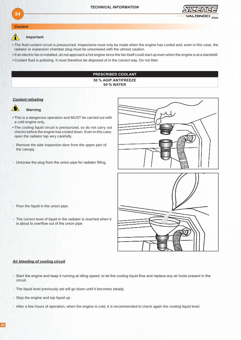
54
EN
TECHNICAL INFORMATION
Coolant
Important
• The fluid coolant circuit is pressurized. Inspections must only be made when the engine has cooled and, even in this case, the radiator or expansion chamber plug must be unscrewed with the utmost caution.
• If an electric fan is installed, do not approach a hot engine since the fan itself could start up even when the engine is at a standstill.• Coolant fluid is polluting. It must therefore be disposed of in the correct way. Do not litter.
Coolant refueling
Warning
• This is a dangerous operation and MUST be carried out with a cold engine only.
• The cooling liquid circuit is pressurized, so do not carry out checks before the engine has cooled down. Even in this case, open the radiator tap very carefully.
- Remove the side inspection door from the upper part of the canopy.
- Unscrew the plug from the union pipe for radiator filling.
- Pour the liquid in the union pipe.
- The correct level of liquid in the radiator is reached when it is about to overflow out of the union pipe
PRESCRIBED COOLANT50 % AGIP ANTIFREEZE
50 % WATER
Air bleeding of cooling circuit
- Start the engine and keep it running at idling speed, to let the cooling liquid flow and replace any air locks present in the circuit.
- The liquid level previously set will go down until it becomes steady.
- Stop the engine and top liquid up.
- After a few hours of operation, when the engine is cold, it is recommended to check again the cooling liquid level.

55
EN
TECHNICAL INFORMATION
Indicators description
Engine protection indicator light
Lights up when the engine is running and all the other indicator lights are off. If everything works correctly, it remains on while the machine is running.
If one of the three following important engine conditions takes place: - the oil pressure is low; - the coolant temperature is too high; - the air filter is clogged
the engine protection indicator light turns off and the failure indicator light turns on. If the failure indicator light remains on for 3 seconds, the engine turns off.
The engine stop takes place by means of a solenoid valve that, in case of failure of the engine basic functions described above, stops the fuel supply.
Revolution counter display with engine protection indicator light
It indicates the engine rotation speed in real time from 0 to 5,000 rpm.At the centre of the revolution counter there is the engine protection indicator light.When the indicator light is green it indicates that everything is working correctly and the engine is running.When the indicator light turns red and starts blinking or is fixed there is a failure.
If one of the three following important engine conditions takes place: - the oil pressure is low; - the coolant temperature is too high; - the air filter is clogged
if the failure indicator light remains on for at least 3 seconds,the engine turns off.
If the fuel is starting to finish the green engine protection indicator light turns red and starts blinking; If the glow plug supply is missing the engine protection indicator light turns green and starts blinking.
Hour counter display
- Indicates engine’s running hours and tenths.
x 1000

56
EN
TECHNICAL INFORMATION
Oil pressure indicator
- Turns on when oil pressure is low. When the indicator light remains fixed for 3 seconds, the engine stop takes place.
- The partly completed machinery technician can use this indicator at his own discretion. Will have to indicate the meaning of this indicator in the final machine's manual.
Battery recharge indicator
- Turns on in the case of a battery recharge failure. When the indicator light remains fixed for 3 seconds, the engine stop takes place.
Plugs indicator (yellow colour)
- Remains on during preheat (The preheating time varies according to the environment temperature: longer in cold periods and shorter in hot periods).
- In the panels without revolution counter, the glow plug indicator light starts blinking when the glow plug supply is missing (burnt-out fuse or relay failure).
- In the panels with revolution counter, during the preheating phase the engine protection indicator light turns green when the glow-plug supply is missing (burnt-out fuse or relay failure).
Oil or cylinder over-temperature indicator
- Turns on when the coolant temperature is above safety level. When the indicator light remains fixed for 3 seconds, the engine stop takes place.
Air filter obstruction indicator
- Turns on in the case of an air filter obstruction.
- The partly completed machinery technician can use this indicator at his own discretion. Will have to indicate the meaning of this indicator in the final machine's manual.
Fuel indicator
- Turns on to indicate "fuel reserve"

57
EN
Warning
• Make sure that all the warning lights are off when the engine is running.
• For engines with starting panel equipped with engine protection, make sure the OK light only keeps ON.
• Do not actuate starter for more than 20 seconds at a time. If engine does not start,wait 1 minute before repeating attempt. If the engine does not start after two attempts, trace the cause according to Diagnosis Chart (see page 67).
1. Insert the key in the ignition switch: first clockwise click - indicators light up.
2. Wait for the "glow plug preheating" indicator to switch off and further rotate the key clockwise to start the engine.
3. At idle speed for a few minutes according to table.
4. While the engine is running, increase or reduce the speed by pressing the proper button (placed over the starting panel) marked by an arrow in the picture.
5. Press the right part of the button to increase speed.
6. Press the left part of the button to reduce speed.
Warning• On start-up, make sure no engine faults are signalled by warning lights. If otherwise, assess if the engine must be stopped immediately or whether it is possible to continue with operations and proceed with restoring it later.
STARTING/STOPPING
Starting
OUTDOOR AMBIENT TEMPERATURE
TIME
≤ - 20° C 5’
- 15° C / - 10° C 2’
- 10° C - 5° C 1’
≥ 5° C 20”
- +

58
EN
STARTING/STOPPING
Stopping
Run-in
Before stopping
- Reduce to minimum speed for a few minutes.
Stopping
- Rotate the key anti-clockwise - Remove the key
- During first 50 hours do not exceed 70% of maximum rated power.
Important
• Maintenance operations to carry out on cold engine .• Use only genuine repair parts. Failure to use genuine parts could result in sub-standard performance and low longevity.• The non-observance of the operations described in the following pages can involve the risk of technical damages to the machine and/or the installation
• Failure to do so will make warranty void.
Maintenance
After the first 50 working hours:
1. Engine oil replacement. 2.Engine oil filter replacement.
Every 10 hours:
1. Check oil level by means of the proper dipstick - Remove the side inspection door from the
upper part of the canopy.
- If oil level is very close to the minimum, top it up. - After checking the level again, insert the dipstick once more.

59
EN
MAINTENANCE
2. Dry air cleaner check:
- To check or replace the air filter, remove the side inspection door.
- Disassemble the filter case by unfastening the hooks provided.
- Check the condition of the filter element and, based on this, clean or replace it.
- Beat the element against a hard surface, with light and repeated movements, so as to remove the excess of grit.
- Carefully clean filter case and support.
Warning
• Always wear protective goggles if compressed air is used.• Use only genuine repair parts.
- Check that the air filter is mounted correctly, to prevent dust and dirt from getting into the intake ducts.
- Replace the filter element in case it has already been cleaned many times or it is completely clogged.
- Reassemble the filtering element and air cleaner.
- For engines with dry air filter and clogging indicator.: Clean or replace f i lter ing element as per above specifications if the indicator shows a clogged state.
- To reach the air filter, remove the side inspection door from the upper part of the canopy.
- Tap filter gently to dislodge debris. Do not wash paper filter or use pressurized air, as this will damage filter.
- Do not reuse air filter or pre-cleaner if any damage or deterioration has occurred. Replace with new.
- Fit air filter back in position.
Warning
• Use only genuine repair parts.
1. Clean air union (on air intake)2. Outside air intake3. Air filter housing4. Filter cartridge5. Lower part of air filter housing6. Dust exhaust valve
2
4
1
3
5
6

60
EN
MAINTENANCE
3. Coolant level check.
1. Unscrew the plug from the union pipe of the coolant.
2. Check that the liquid is visible. If it is not the case, top liquid up.
Warning• This is a dangerous operation and MUST be carried out with a cold engine only.
• The cooling liquid circuit is pressurized, so do not carry out checks before the engine has cooled down. Even in this case, open the radiator tap very carefully.
Every 300 hours or 1 year:
1. Engine oil replacement
Warning
• To quickly and completely drain off the engine oil, it is advisable to carry out this operation when the engine is hot.
• The used engine oil can cause skin-cancer if kept frequently in contact for prolonged periods. If contact with oil cannot be avoided, wash carefully your hands with water and soap as soon as possible.
• Do not disperse the oil in the environment, as it has a high pollution power.
- Run the pump (see picture) in order to drain the engine oil.
- Remove oil filter cap.
- Pour oil very slowly to prevent it from spilling out. After refilling, screw the plug back into its housing.
- Check that oil is at its maximum with the engine on a flat level.
WarningBefore restarting, make sure that the oil dipstick and the oil drain and fill plugs have been correctly fitted back in place to prevent lubricant from spilling out.
2. Alternator belt stretch control:
Important
• Contact authorised workshops.
MAX
.M
IN.

61
EN
MAINTENANCE
3. Engine oil filter replacement:
- Unscrew the oil filter with a proper adjustable strap wrench.
- The new oil filter cartridge must be tightened manually after having lubricated the rubber gasket.
Warning• When replacing the oil filter and the fuel filter, keep them separated from other waste.
• Use only genuine repair parts.
4 . Fuel filter replacement:
- By means of the proper wrench, the same as that used previously for the oil filter, disassemble the fuel filter.
- When reassembling the new fuel filter cartridge, the rubber gasket on the internal circle must also be replaced and the one on the external surface is to be lubricated. Tighten the cartridge manually.
5 . Check cooling circuit sleeves:
- Carefully check the wear of the hoses through which the coolant flows. .
- Replace sleeves if worn out (Contact authorised workshops).
Every 600 hours:
1. Alternator belt replacement:
Important
• Contact authorised workshops.
2. Replacement sleeves:
Important
• Contact authorised workshops.

62
EN
MAINTENANCE
3. Radiator efficiency check:
- If the radiator element is clogged, clean with a brush and fuel oil.
- Blow the radiator with compressed air.
........................................................................................................................................................
........................................................................................................................................................
........................................................................................................................................................
........................................................................................................................................................
........................................................................................................................................................
........................................................................................................................................................
........................................................................................................................................................
........................................................................................................................................................
........................................................................................................................................................
........................................................................................................................................................
........................................................................................................................................................
........................................................................................................................................................
........................................................................................................................................................
........................................................................................................................................................
........................................................................................................................................................
........................................................................................................................................................
........................................................................................................................................................
........................................................................................................................................................
NOTES
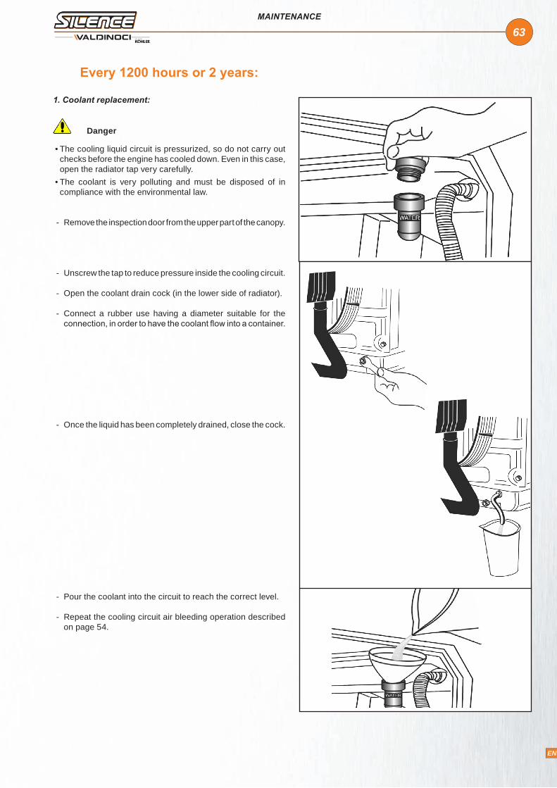
63
EN
Every 1200 hours or 2 years:
1. Coolant replacement:
Danger
• The cooling liquid circuit is pressurized, so do not carry out checks before the engine has cooled down. Even in this case, open the radiator tap very carefully.
• The coolant is very polluting and must be disposed of in compliance with the environmental law.
- Remove the inspection door from the upper part of the canopy.
- Unscrew the tap to reduce pressure inside the cooling circuit.
- Open the coolant drain cock (in the lower side of radiator).
- Connect a rubber use having a diameter suitable for the connection, in order to have the coolant flow into a container.
- Once the liquid has been completely drained, close the cock.
- Pour the coolant into the circuit to reach the correct level.
- Repeat the cooling circuit air bleeding operation described on page 54.
MAINTENANCE

64
EN
MAINTENANCE
Every 600 hours:
Valve clearance adjustment:
Warning• Adjustments and controls must be carried out on cold engine.
- Remove the rocker-arm cover
- Turn the camshaft gear until the piston reaches the top dead center during compression. Loosen the locking nuts on the adjusting screws
- Insert a thickness gauge (0.15 mm) between the rocker-arm pin and the bottom of the camshaft.
- Tighten the adjusting screws until the thickness gauge can be pulled out easily.
- Tighten the locking nuts on the adjusting screws.
Every 1200 hours:
Setting and injectors cleaning:
Warning• To clean and set the injectors, use a high pressure pump for injector testing and the specific equipment provided.
- Disassemble the injector
- Connect it to the pressure-gauge equipped, high pressure pump by means of the metal strip provided –
- Start the pump
- Check that spraying is correct and setting pressure is kg/cm² 150 ±10.
After 5000 hours:
1. Partial overhaul:
- Valve and seat grinding
- Pump injector overhaul
- Injection spark advance check
- Crankshaft end float check and camshaft wear check
2. Replacement of toothed and timing belt:
The toothed and timing belt has been designed and tested to work for 5000 hours. For its manufacturing characteristics, the belt must be replaced each time it is disassembled.
After 10000 hours:
Overhaul:
Total overhaul as above plus:
- Cylinder grinding/boring operations and piston replacement
- Grinding/boring operations or replacement of valve seats, guides, valves, crankshaft, main bearing and connecting rod bearing, if necessary.
- If no spraying is carried out, unscrew the sprayer ring nut and check that the sprayer nozzle is not dirty or burnished due to excessive temperature. If spraying is carried out but setting pressure is lower than indicated, increase thickness of pressure setting shims. If pressure goes over the indicated level, reduce shim thickness.
Important
FOLLOWING OPERATIONS SHOULD BE PERFORMED BY AUTHORIZED PERSONNEL TRAINED ON THE PRODUCT.
Special maintenance

65
EN
STORAGE
Important
WHEN THE ENGINES ARE NOT BE USERD FOR MORE THAN 3 MONTHS, THEY HAVE TO BE PROTECTED PERFORMING THE OPERATIONS DESCRIBED IN THE FOLLOWING PAGES.
Storage
Engine storage (not installed)
Protective treatment
- If the Silence is not to be used for long periods, check the storage environment, the type of packaging and make sure these conditions will allow proper maintenance.
- If necessary, cover the Silence with protective sheeting.
- Do not store the Silence directly on the ground, in damp environments, in areas exposed to the elements, near sources of danger, including less visible hazards such as highvoltage power lines, etc.
Warning• If the Silence is not to be used for more than 1 month, it is necessary to apply protective measures that are valid for 6 months (see “Protective treatment”).
Important
• If, after the first 6 months, the Silence is still not to be used, it is necessary to carry out further measures to extend the protection period (see “Protective treatment”).
1 - Check that the engine oil and coolant are up to level.
2 - Fill up with fuel containing 10% AGIP RUSTIA NT
3 - Run the engine at minimum idle speed for 15 minutes.
4 - Switch off the engine.
5 - Remove the lubrication oil.
6 - Fill the sump with protective oil: AGIP RUSTIA.
7 - Start the engine and check for fuel and oil leaks.
8 - Bring the engine to ¾ of the maximum speed for 5-10 minutes.
9 - Switch off the engine.
10 - Empty the fuel tank completely.
11 - Replace the fuel filter.
12 - Spray SAE 10W oil on the exhaust and intake manifolds.
13 - Close all openings to prevent foreign bodies from entering.
14 - Thoroughly clean all external parts of the engine using suitable products.
15 - Treat non-painted parts with protective products (AGIP RUSTIA 100/F).
16 - Loosen the alternator/fan belt.
17 - If necessary, cover the engine with protective sheeting.
Warning • In countries in which AGIP products are not available, find an equivalent product.
Important
• After a year of engine inactivity, the coolant loses its properties and must be replaced.

66
EN
STORAGE
Preparing the engine for operation after protective treatment
After a period of inactivity and before installing and running the engine, it is necessary to carry out a few measures in order to ensure that it runs at maximum efficiency.
1 - Remove the protective sheeting.2 - Eliminate any blockages in the exhaust and intake ducts.3 - Use a cloth soaked in degreasing product to remove the external protective treatment.4 - Remove the intake manifold.5 - Inject lubrication oil (no more than 2 cm3) into the valves and install the intake manifold.6 - Adjust the alternator/fan belt tension.7 - Turn the flywheel manually to check the movement of the mechanical parts.8 - Refill the tank with fresh fuel.9 - Start the engine and run at ¾ of the maximum speed for 5-10 minutes.10 - Switch off the engine.11 - Remove the protective oil to replace with engine oil.12 - Introduce new oil (see “Lubricants”) up to the correct level marked on the dipstick.13 - Replace the filters (air, oil, fuel) with original spare parts.14 - Empty the cooling circuit completely and pour in the new coolant up to the correct level.
Warning • Over time, a number of engine components and lubricants lose their properties, even when the engine is not in use, and so it is important to consider whether they need replacing, based not only on the "working hours", but also on age and wear.
15 - Install the engine and make the necessary connections and unions.16 - Make sure that electrical contacts are intact and efficient.17 - Check that the engine oil and coolant are up to level.18 - Start the engine and keep at minimum speed for a few minutes.19 - Check for leaks and, if necessary, find and eliminate the cause.20 - Switch off the engine.21 - Double check that the engine oil and coolant are up to level.
........................................................................................................................................................
........................................................................................................................................................
........................................................................................................................................................
........................................................................................................................................................
........................................................................................................................................................
........................................................................................................................................................
........................................................................................................................................................
........................................................................................................................................................
........................................................................................................................................................
NOTES

67
EN
Table of likely anomalies and their symptoms
ANOMALIES
Important
THE ENGINE MUST BE STOPPED IMMEDIATELY WHEN:1) - The engine rpms suddenly increase and decrease
2) - A sudden and unusual noise is heard
3) - The colour of the exhaust fumes suddenly darkens
4) - The oil pressure indicator light turns on while running
TROUBLES
PROBABLE CAUSEFa
ilure
to s
tart
Sta
rt an
d st
ops
Sta
rt an
d st
ops
Uns
tead
y sp
eed
Bla
ck s
mok
e
Whi
te s
mok
e
Low
oil p
ress
ure
MA
INTE
NA
NC
E Clogged air filter
Excessive idle operation
Incomplete run-in
Overloaded
SETT
ING
S / R
EPA
IRS
Incorrect injection timing
Governor linkage wrongly set
Governor spring broken
Low idle speed
Rings worn or sticking
Worn cylinder
Valves sticking
Worn main con. rods bearings
Loose cylinder locknuts
FUEL
SYS
TEM
Obstructed fuel line
Fuel filter clogged
Air leaks in fuel system
Clogged tank vent hole
Injector sticking

68
EN
PROBABLE CAUSE
TROUBLES
Failu
re to
sta
rt
Sta
rt an
d st
ops
Sta
rt an
d st
ops
Uns
tead
y sp
eed
Bla
ck s
mok
e
Whi
te s
mok
e
Low
oil
pres
sure
FUEL
SYS
TEM
Injection pump valve sticking
Injector not adjusted
Faulty fuel feeding pump
Hardened inj. pump rack
Extra fuel control level sticking
LUB
RIC
ATIO
N
Oil level too high
Oil pressure sticking
Oil pressure regulator not adjusted
Worm oil pump
Air into oil suction line
Faulty pressure gauge or pressure switch
Oil suction line clogged
ELEC
TRIC
AL
SYS
TEM
Batterie entladen
Cable connections uncertain or incorrect
Faulty starting switch
Faulty starting motor
ANOMALIES
........................................................................................................................................................
........................................................................................................................................................
........................................................................................................................................................
........................................................................................................................................................
........................................................................................................................................................
........................................................................................................................................................
........................................................................................................................................................
........................................................................................................................................................
........................................................................................................................................................
NOTES

EN
Istruzioni originali in lingua ITALIANA: Questo documento è stato emesso originariamente in lingua Italiana. In presenza di eventuali controversie dovute alle traduzioni il testo di riferimento sarà unicamente la versione italiana.
Original instructions in ITALIAN: This document was originally issued in Italian. Should there be any dispute due to translations, the authoritative version remains solely the Italian version.
CODICE/CODE REV. DATA/DATE REV.
SM01_1 02 02/2016
VALDINOCI LUIGI S.P.A.,


