28
ICPlus 915 Electronic controller with 2 intervention points EN

ICPlus 915
Electronic controller with 2 intervention pointsEN
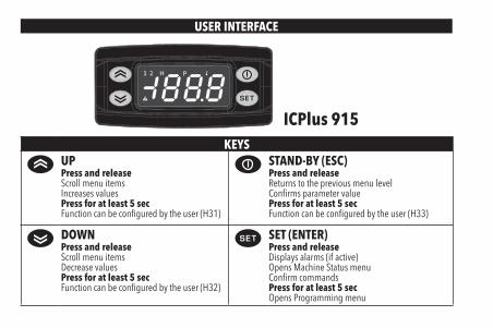
USER INTERFACE
ICPlus 915KEYS
UPPress and releaseScroll menu itemsIncreases valuesPress for at least 5 secFunction can be configured by the user (H31)
STAND-BY (ESC)Press and releaseReturns to the previous menu levelConfirms parameter valuePress for at least 5 secFunction can be configured by the user (H33)
DOWNPress and releaseScroll menu itemsDecrease valuesPress for at least 5 secFunction can be configured by the user (H32)
SET (ENTER)Press and releaseDisplays alarms (if active)Opens Machine Status menuConfirm commandsPress for at least 5 secOpens Programming menu

ICONsDecimal Point TemperaturePermanently on: decimal point Permanently on: displays a temperatureFlashing: Soft Start active Flashing: reduced set active, displays
a temperature or no unit of measure selected
Off: otherwise
Pressure HumidityPermanently on: displays a pressure Permanently on: displays a humidityFlashing: reduced set active and displays
a pressureFlashing: reduced set active and displays
a humidity
Relay OUT1 Relay OUT2Permanently on: OUT1 output active Permanently on: OUT2 output activeFlashing: a delay, a protection or a locked
start-upFlashing: a delay, a protection or a locked
start-upOff: otherwise Off: otherwise
Alarm NOTE:When switched on, the device performs a Lamp Test; the display and LEDs will flash for several seconds to check that they all function correctly.
Permanently on: alarm activeFlashing: alarm acknowledgedOff: otherwise

NTC/PTC MODELCONNECTIONS INPUT/OUTPUT CHARACTERISTICS
Display range:NTC: -50...110°C (-58...230°F)PTC: -50...140°C (-58...302°F)on display with 3½ digits + sign
Digital input 1 digital voltage free input
Analogue input 1 NTC or 1 PTC(selectable by parameter H00)
Serial TTL for connection to Copy Card or Televis/Modbus remote control systems
Digital outputs OUT1: 1 SPDT relay 8(4)A 250 Va
OUT2: 1 SPST relay 8(4)A 250 Va
Buzzer output only on models where this is providedMeasurement range -50 ... 140°C (-58 ... 284°F)Accuracy better than 0.5% of end of scale +1 digitResolution 0.1°C (0.1°F up to +199.9°F; 1°F over)
NTC/PTC (12Va/c, 12-24Va/12-36Vc)
D.I.
Supply Pb1
OUT1 OUT2
1 2 3 4 5 7 8 9 10 11 12
NTC/PTC (24Va, 115Va, 230Va)D.
I.
Supply Pb1
OUT1 OUT2
1 2 3 4 5 6 7 9 10 11 12
TERMINALS1-2-3 regulator relay OUT1 *7-8 Power supply 12Va/c and 12-24Va/12-36Vc.4-5 regulator relay OUT2 9-11 Probe Pb1 Input
*6-7 Power supply 24Va, 115Va and 230Va. 9-12 Digital Input (D.I.)A TTL input for Copy Card and TelevisSystem connection * depends on model
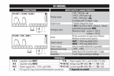
V/I MODELCONNECTIONS INPUT/OUTPUT CHARACTERISTICS
Display range:
-199...199 (ndt = n)-199.9...199.9 (ndt = y)-1999...1999 (ndt = int)on display with 3½ digits + sign
Digital input 1 digital voltage free input
Analogue input
1 V/I (0-1V, 0-5V, 0-10V, 0...20mA, 4...20mA)(selectable by parameter H00)Maximum load: - current = 100 Ω
- voltage = 20 kΩ
Serial TTL for connection to Copy Card or Televis/Modbus remote control systems
Digital outputs OUT1: 1 SPDT relay 8(4)A 250 Va
OUT2: 1 SPST relay 8(4)A 250 Va
Buzzer output only on models where this is providedMeasurement range -1999 ... 1999Accuracy better than 0.5% of end of scale +1 digitResolution 1 or 0.1 digit according to settings
V/I (12Va/c, 12-24Va/12-36Vc)
+12VI
V+ +−
Supply
OUT1 OUT2
1 2 3 4 5 7 8 9 10 11 12
V/I (24Va, 115Va, 230Va)
+12VI
V+ +−
Supply
OUT1 OUT2
1 2 3 4 5 7 9 10 11 126
TERMINALS1-2-3 regulator relay OUT1 *7-8 Power supply 12Va/c and 12-24Va/12-36Vc.4-5 regulator relay OUT2 *9-10-12 Voltage input (9=GND; 10=”+”; 12=12V)
*6-7 Power supply 24Va, 115Va and 230Va. *9-11-12 Current input (9=GND; 11=”+”; 12=12V)A TTL input for Copy Card and TelevisSystem connection * depends on model
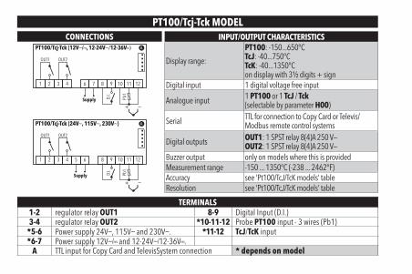
PT100/Tcj-Tck MODELCONNECTIONS INPUT/OUTPUT CHARACTERISTICS
Display range:
PT100: -150...650°CTcJ: -40...750°CTcK: -40...1350°Con display with 3½ digits + sign
Digital input 1 digital voltage free input
Analogue input 1 PT100 or 1 TcJ / Tck(selectable by parameter H00)
Serial TTL for connection to Copy Card or Televis/Modbus remote control systems
Digital outputs OUT1: 1 SPST relay 8(4)A 250 Va
OUT2: 1 SPST relay 8(4)A 250 Va
Buzzer output only on models where this is providedMeasurement range -150 ... 1350°C (-238 ... 2462°F)Accuracy see ‘Pt100/TcJ/TcK models’ tableResolution see ‘Pt100/TcJ/TcK models’ table
PT100/Tcj-Tck (12Va/c, 12-24Va/12-36Vc)
D.I.
Supply Pb1
+ −
OUT2
1 2 3 4 6 7 8 9 10 11 12
OUT1
PT100/Tcj-Tck (24Va, 115Va, 230Va)
D.I.
Supply Pb1
+ −
OUT2
1 2 3 4 5 6 8 9 10 11 12
OUT1
TERMINALS1-2 regulator relay OUT1 8-9 Digital Input (D.I.)3-4 regulator relay OUT2 *10-11-12 Probe PT100 input - 3 wires (Pb1)
*5-6 Power supply 24Va, 115Va and 230Va. *11-12 TcJ/TcK input*6-7 Power supply 12Va/c and 12-24Va/12-36Vc.
A TTL input for Copy Card and TelevisSystem connection * depends on model

PT100/Tcj-Tck MODELs
PT100:ACCURACY: 0.5% for whole scale + 1 digit
0.2% from -150 to 300°CRESOLUTION: 0.1°C (0.1°F) from -199.9°C up to 199.9°C; 1°C (1°F) beyond
TcJ:ACCURACY: 0.4% for whole scale + 1 digitRESOLUTION: 0.1°C (0.1°F) from -199.9°C up to 199.9°C; 1°C (1°F) beyond
Tck:ACCURACY: 0.5% for whole scale + 1 digit
0.3% from -40 to 800°CRESOLUTION: 0.1°C (0,1°F) from -199.9°C up to 199.9°C; 1°C (1°F) beyond
MOUNTING - DIMENSIONSThe device is designed for panel mounting. Drill a 29x71 mm hole and insert the instrument; secure it with the special brackets provided.Do not install the instrument in damp and/or dirty places; in fact, it is suitable for use in places with ordinary or normal levels of pollution.Keep the area around the instrument cooling slots adequately ventilated.
74 mm
32 m
m
29 m
m
71 mm70 mm
59 m
m
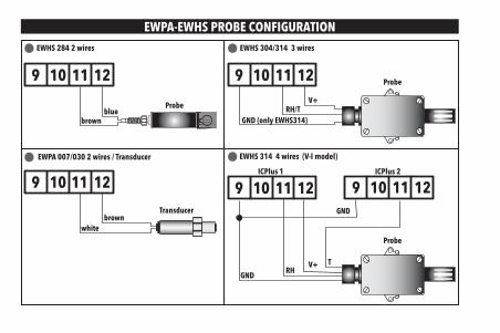
EWPA-EWHS PROBE CONFIGURATION
EWPA 007/030 2 wires / Transducer
Transducerbrown
white
9 10 11 12
EWHS 304/314 3 wires
Probe
GND (only EWHS314)
V+RH/T
9 10 11 12
EWHS 284 2 wires
Probe
brownblue
9 10 11 12
EWHS 314 4 wires (V-I model)
Probe
GNDV+
RHT
GND
ICPlus 1 ICPlus 2
9 10 11 12 9 10 11 12

ACCESSING AND USING THE MENUsThe resources are organized into 2 menus which are accessed as follows:
• ‘Machine Status’ menu: press and release the key.• ‘Programming’ menu: hold down the key for 5 seconds.
Either do not press any keys for 15 seconds (timeout) or press the key once, to confirm the last value displayed and return to the previous screen.
PASSWORDPassword ‘PA1’: used to access User parameters. The password is not enabled by default (PS1=0).To enable it (PS1≠0): press and hold for longer than 5 seconds, scroll through the parameters using and until you see the label PS1, press to display the value, modify it using and , then save it by pressing or . If enabled, it will be required in order to access the User parameters.
Password ‘PA2’: used to access Installer parameters. The password is enabled by default (PS2=15).To modify it (PS2≠15): press and hold for longer than 5 seconds, scroll through the parameters using and until you see the label PA2, press , set the value to ‘15’ using and , then confirm using . Scroll through the folders until you find the label diS and press to enter. Scroll through the parameters using and until you see the label PS2, press to display the value, modify it using and , then save it by pressing or .
The visibility of ‘PA2’ is as follows:
1) PA1 and PA2 ≠ 0: Press and hold for longer than 5 seconds to display PA1 and PA2. It will then be possible to decide whether to access the User parameters (PA1) or the Installer parameters (PA2).
2) Otherwise: The password PA2 is amongst the level1 parameters. If enabled, it will be required when accessing the Installer parameters; to enter it, proceed as instructed for password PA1.
If the value entered is incorrect, the label PA1/PA2 will be displayed again and the procedure will need to be repeated.
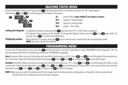
MACHINE STATUS MENUAccess the Machine Status menu by pressing and releasing the key. If no alarms are active, the ‘SP1’ label appears.Use the keys and to scroll through all the folders in the menu:
- AL: alarms folder (only visible if an alarm is active);- SP1: Setpoint 1 setting folder;- SP2: Setpoint 2 setting folder;- Pb1: probe 1 - Pb1 folder;
Setting the Setpoint: To display the Setpoint value press the key when the ‘SP1’ or ‘SP2’ label is displayed.The Setpoint value appears on the display. To change the Setpoint value, press the and keys within 15 seconds. Press to confirm the modification.
Displaying probes: When label Pb1 is present, press the key to view the value measured by the corresponding probe(NOTE: the value cannot be modified).
PROGRAMMING MENUTo access the ‘Programming’ menu, press the key for more than 5 seconds. If specified, an access PASSWORD will be requested: ‘PA1’ for User parameters and ‘PA2’ for Installer parameters (see ‘PASSWORD’ paragraph).
User Parameter: When accessed, the display will show the first parameter (e.g. ‘dF1’). Press and to scroll through all the parameters on the current level. Select the desired parameter by pressing . Press and to modify it and to save the changes.
Installer Parameter: When accessed, the display will show the first folder (e.g. ‘rE1’). Press and to scroll through the folders on the current level. Select the desired folder using . Press and to scroll through the parameters in the current folder and select the parameter using . Press and to modify it and to save the changes.
NOTE: Make sure you switch the instrument off and on again each time the parameter configuration is changed, in order to prevent mal-functioning in the configuration and/or timing in progress.

DIAGNOSTICSAlarms are always indicated by the alarm icon , the buzzer and the relay (if setting).To switch off the buzzer, press and release any key; the corresponding icon will continue to flash.
N.B.: If alarm exclusion times have been set (see ‘AL’ folder in the parameters table) the alarm will not be signalled.
ALARMsLabel Fault Cause Effects Remedy
E1 Probe1 faulty(ambient)
• measured values are outside operating range
• Probe faulty/short-circuited/open
• Display label E1• Alarm icon permanently on• Buzzer and Alarm relay (if setting) activation• Disable max/min alarm controller• Compressor operation based on parameters
On1/2 and OF1/2
• check probe type (H00)• check probe wiring• replace probe
AH1/2 Alarm for HIGHvalue (Probe1)
value read by Pb1 > HA1/2 after time of tAO.(see ‘MAX/MIN TEMP. ALARMS’)
• Recording of label AH1/2 in folder AL• Alarm icon permanently on• Buzzer and Alarm relay (if setting) activation• No effect on regulation
Wait until value read by Pb1 returns below HA1/2.
AL1/2 Alarm for LOWvalue (Probe1)
value read by Pb1 < LA1/2 after time of tAO.(see ‘MAX/MIN TEMP. ALARMS’)
• Recording of label AL1/2 in folder AL• Alarm icon permanently on• Buzzer and Alarm relay (if setting) activation• No effect on regulation
Wait until value read by Pb1 returns above LA1/2.
EA External alarm Digital input activated(H11 = ±5)
• Recording of label EA in folder AL• Alarm icon permanently on• Buzzer and Alarm relay (if setting) activation• Regulation locked
Check and remove the external cause which triggered the alarm on the D.I.
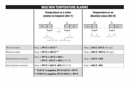
MAX/MIN TEMPERATURE ALARMSTemperature as a value
relative to Setpoint (Att=1)Temperature as an
Absolute value (Att=0)
SP1/SP2 + LA1/2
AFd
SP1/SP2 + HA1/2
AFd
SP1/SP2 + LA1/2 + AFd SP1/SP2 + HA1/2 – AFd
SP1/SP2
LA1/2
AFd
HA1/2
AFd
LA1/2 + AFd LA1/2 - AFd
Minimum alarm Temp. ≤ SP1/2 + LA1/2 * Temp. ≤ LA1/2 (LA1/2 with sign)
Maximum alarm Temp. ≥ SP1/2 + HA1/2 ** Temp. ≥ HA1/2 (HA1/2 with sign)
Returning from minimumTemp. ≥ SP1/2 + LA1/2 + AFd or
≥ SP1/2 - ILA1/2I + AFd (LA1/2<0)Temp. ≥ LA1/2 + AFd
Returning from maximum Temp. ≤ SP1/2 + HA1/2 - AFd (HA1/2>0) Temp. ≤ HA1/2 - AFd
* if LA1/2 is negative, SP1/2+LA1/2 < SP1/2** if HA1/2 is negative, SP1/2+HA1/2 < SP1/2
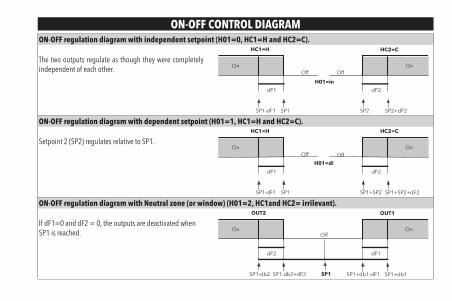
ON-OFF CONTROL DIAGRAMON-OFF regulation diagram with independent setpoint (H01=0, HC1=H and HC2=C).
The two outputs regulate as though they were completely independent of each other.
SP1SP1-dF1
dF1
OffOn
SP2+dF2SP2
dF2
OffOn
HC1=H
H01=in
HC2=C
ON-OFF regulation diagram with dependent setpoint (H01=1, HC1=H and HC2=C).
Setpoint 2 (SP2) regulates relative to SP1.
SP1SP1-dF1
dF1
OffOn
SP1+SP2+dF2SP1+SP2
dF2
OffOn
HC1=H
H01=di
HC2=C
ON-OFF regulation diagram with Neutral zone (or window) (H01=2, HC1and HC2= irrilevant).
If dF1=0 and dF2 = 0, the outputs are deactivated when SP1 is reached.
SP1-db2+dF2SP1-db2
dF2
OffOn
SP1+db1SP1+db1-dF1
dF1
On
OUT2 OUT1
SP1

TELEVIS SYSTEM
The Televis remote control systems can be connected using the TTL serial port (TTL-RS485 BusAdapter 130 or 150 interface module must be used).
To configure the instrument to do this, you need to access the Add folder and use the dEA and FAA parameters. RS485
BusA
dap
ter
ICPlus
TTL
IMPORTANT! CHECK THE AVAILABILITY OF MODELSCOMPATIBLE WITH REMOTE SUPERVISION SYSTEMS.
DUTY CYCLE DIAGRAM
The device uses parameters On1/2 e OF1/2 set for Duty Cycle.An error condition in probe1 (regulation) causes one of the following actions:
• Code ‘E1’ is shown on the display• The regulator is activated as indicated by parameters On1/2 and OF1/2 if set for Duty Cycle
On1/2 OF1/2 Regulator output0 0 OFF0 >0 OFF
>0 0 ON>0 >0 Duty Cycle OF1/2
OFFON
OUT
On1/2 On1/2
ON
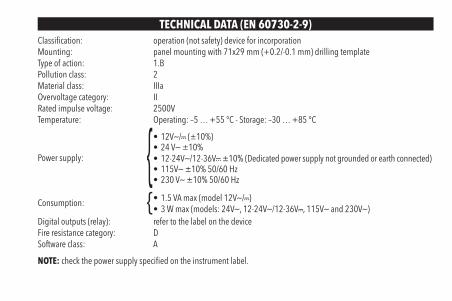
TECHNICAL DATA (EN 60730-2-9)Classification: operation (not safety) device for incorporationMounting: panel mounting with 71x29 mm (+0.2/-0.1 mm) drilling templateType of action: 1.BPollution class: 2Material class: IIIaOvervoltage category: IIRated impulse voltage: 2500VTemperature: Operating: –5 … +55 °C - Storage: –30 … +85 °C
Power supply:
• 12Va/c (±10%)• 24 Va ±10%• 12-24Va/12-36Vc ±10% (Dedicated power supply not grounded or earth connected)• 115Va ±10% 50/60 Hz• 230 Va ±10% 50/60 Hz
Consumption: • 1.5 VA max (model 12Va/c)• 3 W max (models: 24Va, 12-24Va/12-36Vc, 115Va and 230Va)
Digital outputs (relay): refer to the label on the deviceFire resistance category: DSoftware class: A
NOTE: check the power supply specified on the instrument label.
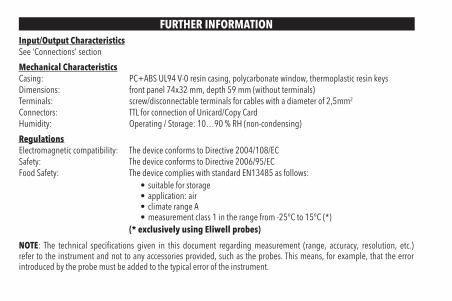
FURTHER INFORMATIONInput/Output CharacteristicsSee ‘Connections’ section
Mechanical CharacteristicsCasing: PC+ABS UL94 V-0 resin casing, polycarbonate window, thermoplastic resin keysDimensions: front panel 74x32 mm, depth 59 mm (without terminals)Terminals: screw/disconnectable terminals for cables with a diameter of 2,5mm2
Connectors: TTL for connection of Unicard/Copy CardHumidity: Operating / Storage: 10…90 % RH (non-condensing)
RegulationsElectromagnetic compatibility: The device conforms to Directive 2004/108/ECSafety: The device conforms to Directive 2006/95/ECFood Safety: The device complies with standard EN13485 as follows:
• suitable for storage• application: air• climate range A• measurement class 1 in the range from -25°C to 15°C (*)
(* exclusively using Eliwell probes)
NOTE: The technical specifications given in this document regarding measurement (range, accuracy, resolution, etc.) refer to the instrument and not to any accessories provided, such as the probes. This means, for example, that the error introduced by the probe must be added to the typical error of the instrument.

USING THE COPY CARDThe Copy Card is connected to the serial port (TTL) and allows rapid programming of the instrument parameters.Access Installer parameters by entering ‘PA2’, scroll through the folders using and until folder FPr appears. Select it using , scroll through the parameters using and , then select the function using (eg. UL).
• Upload (UL): Select UL and press . This function uploads the programming parameters from the instrument to the card. If the procedure is a success, ‘y’, will appear on the display, otherwise ‘n’ will appear.
• Format (Fr): This command is used to format the copy card (recommended when using the card for the first time).Important: the Fr parameter deletes all data present. This operation cannot be cancelled.
• Download: Connect the Copy Card when the instrument is switched off. At power-on, data is downloaded from the copy card to the instrument automatically. At the end of the lamp test, the display will show ‘dLy’ if the operation was successful and ‘dLn’ if not.
NOTE: After downloading, the instrument works with the settings of the new map just downloaded.
H13 PARAMETER CONFIGURATION
H13 D.I.STATE
FROM KEY OR FROM MENU FUNCTIONSTATE COMMENTSENABLED DISABLED
NO open YES YES ON enabled / disabled with each modeNO closed YES YES OFF enabled / disabled with each modeNC open YES YES OFF enabled / disabled with each modeNC closed YES YES ON enabled / disabled with each mode
NOP open YES YES ON enabled only from D.I. / disabled with each modeNOP closed NO N/A OFF Enabled only when D.I. is reopenedNCP open YES YES OFF enabled with each mode / disabled only from D.I.NCP closed N/A NO ON enabled with each mode / disabled only from D.I.

PARAMETERS TABLEPAR. DESCRIPTION MODEL RANGE VALUE M.U. LEVEL
SP1 Pb1 value control setpoint SP1. The SEtpoint is visible from the machine status menu and not from the programming menu.
NTC/PTCLS1...HS1
0.0 °C/°FPT100-Tc 0.0 °C/°F
V/I 0 num
SP2 Pb1 value control setpoint SP2. The SEtpoint is visible from the machine status menu and not from the programming menu.
NTC/PTCLS2...HS2
0.0 °C/°FPT100-Tc 0.0 °C/°F
V/I 0 numREGULATOR 1 (folder ‘rE1’)
HC1 This sets the controller 1 operating mode.H (0) = Hot; C (1) = Cold. ALL H/C H flag Inst
OS1 Value to be added to SP1 if reduced set enabledNTC/PTC -30.0...30.0 0.0 °C/°F
InstPT100-Tc -30.0...30.0 0.0 °C/°FV/I -30...30 0 num
db1 Operating band 1.(See ‘ON/OFF regulation diagram’)
NTC/PTC 0.0...30.0 1.0 °C/°FInstPT100-Tc 0.0...30.0 1.0 °C/°F
V/I 0...30 1 num
dF1Regulator 1 activation differential.The utility stops on reaching the SP1 value (as indicated by control probe) and restarts at a value equal to T=SP1+dF1 relative to HC1.
NTC/PTC 0.0...30.0 1.0 °C/°FUser/InstPT100-Tc 0.0...30.0 1.0 °C/°F
V/I 0...30 1 num
HS1 Maximum value assignable to setpoint SP1.NTC/PTC
LS1...HdL140.0 °C/°F
User/InstPT100-Tc 1350 °C/°FV/I 199 num
LS1 Minimum value assignable to setpoint SP1.NTC/PTC
LdL...HS1-50.0 °C/°F
User/InstPT100-Tc -199.9 °C/°FV/I -199 num
HA1 Pb1 maximum value alarm on regulator 1.(See ‘Max/Min temperature alarms’)
NTC/PTC LA1...150.0 140.0 °C/°FUser/InstPT100-Tc LA1...1999 1350 °C/°F
V/I LA1...150 150 num

PAR. DESCRIPTION MODEL RANGE VALUE M.U. LEVEL
LA1 Pb1 minimum value alarm on regulator 1.(See ‘Max/Min temperature alarms’)
NTC/PTC -150.0...HA1 -50.0 °C/°FUser/InstPT100-Tc -328...HA1 -199.9 °C/°F
V/I -150...HA1 -150 num
dn1 Switch-on delay. The indicated time must elapse between the request for activation of the controller 1 relay and switch-on. 0 = not active. ALL 0...250 0 secs Inst
dO1 Delay time after switching off. The indicated time must elapse between deactivation of the controller 1 relay and the next switch-on. 0 = not active. ALL 0...250 0 min Inst
di1 Delay between switch-ons. The indicated time must elapse between two consecutive switch-ons of regulator 1. 0 = not active. ALL 0...250 0 min Inst
dE1 Switch-off delay. The indicated time must elapse between the request for deactivation of the controller 1 relay and switch-off. 0 = not active. ALL 0...250 0 secs Inst
On1Controller 1 switch-on time in the event of faulty probe.if On1=1 and OF1=0, the controller remains on;if On1=1 and OF1>0, the controller operates in Duty Cycle mode.
ALL 0...250 0 min Inst
OF1Controller 1 switch-off time in the event of faulty probe.if OF1=1 and On1=0, the controller remains off;if OF1=1 and On1>0, the controller operates in Duty Cycle mode.
ALL 0...250 1 min Inst
REGULATOR 2 (folder ‘rE2’)
HC2 This sets the controller 2 operating mode.H (0) = Hot; C (1) = Cold. ALL H/C H flag Inst
OS2 Value to be added to SP2 if reduced set enabledNTC/PTC -30.0...30.0 0.0 °C/°F
InstPT100-Tc -30.0...30.0 0.0 °C/°FV/I -30...30 0 num
db2 Operating band 2.(See ‘ON/OFF regulation diagram’)
NTC/PTC 0.0...30.0 1.0 °C/°FInstPT100-Tc 0.0...30.0 1.0 °C/°F
V/I 0...30 1 num

PAR. DESCRIPTION MODEL RANGE VALUE M.U. LEVEL
dF2Regulator 2 activation differential. The utility stops on reaching the SP2 value (as indicated by control probe) and restarts at a value equal to T=SP2+dF2 relative to HC2.
NTC/PTC 0.0...30.0 1.0 °C/°FUser/InstPT100-Tc 0.0...30.0 1.0 °C/°F
V/I 0...30 1 num
HS2 Maximum value assignable to setpoint SP2.NTC/PTC
LS2...HdL140.0 °C/°F
User/InstPT100-Tc 1350 °C/°FV/I 199 num
LS2 Minimum value assignable to setpoint SP2.NTC/PTC
LdL...HS2-50.0 °C/°F
User/InstPT100-Tc -199.9 °C/°FV/I -199 num
HA2 Pb1 maximum value alarm on Regulator 2.(See ‘Max/Min temperature alarms’)
NTC/PTC LA2...150.0 140.0 °C/°FUser/InstPT100-Tc LA2...1999 1350 °C/°F
V/I LA2...150 150 num
LA2 Pb1 minimum value alarm on Regulator 2.(See ‘Max/Min temperature alarms’)
NTC/PTC -150.0...HA2 -50.0 °C/°FUser/InstPT100-Tc -328...HA2 -199.9 °C/°F
V/I -150...HA2 -150 num
dn2 Switch-on delay. The indicated time must elapse between the request for activation of the controller 2 relay and switch-on. 0 = not active. ALL 0...250 0 secs Inst
dO2 Delay time after switching off. The indicated time must elapse between deactivation of the controller 2 relay and the next switch-on. 0 = not active. ALL 0...250 0 min Inst
di2 Delay between switch-ons. The indicated time must elapse between two consecutive switch-ons of regulator 2. 0 = not active. ALL 0...250 0 min Inst
dE2 Switch-off delay. The indicated time must elapse between the request for deactivation of the controller 2 relay and switch-off. 0 = not active. ALL 0...250 0 secs Inst
On2Controller 2 switch-on time in the event of faulty probe.if On2=1 and OF2=0, the controller remains on;if On2=1 and OF2>0, the controller operates in Duty Cycle mode.
ALL 0...250 0 min Inst

PAR. DESCRIPTION MODEL RANGE VALUE M.U. LEVEL
OF2Controller 2 switch-off time in the event of faulty probe.if OF2=1 and On2=0, the controller remains off;if OF2=1 and On2>0, the controller operates in Duty Cycle mode.
ALL 0...250 1 min Inst
SOFT START CONTROLLER (folder ‘SFt’)
dSi Value of each subsequent increase (dynamic) of the setpoint.0 = disabled.
NTC/PTC 0.0...25.0 0.0 °C/°FInstPT100-Tc 0.0...25.0 0.0 °C/°F
V/I 0...25 0 numdSt Time between two subsequent increases (dynamic) of the Setpoint. ALL 0...250 0 hours InstUnt Unit of measurement (parameter dSt). 0 = hours; 1 = minutes; 2 = seconds. ALL 0/1/2 0 num Inst
Sen Establishes which outputs the function must be enabled on:0 = disabled; 1 = OUT 1; 2 = OUT 2; 3 = OUT 1 & 2 ALL 0/1/2/3 0 num Inst
Sdi Function reactivation threshold. Establishes the threshold beyond which the SOFT START function is automatically reactivated.
NTC/PTC 1.0...50.0 2,0 °C/°FInstPT100-Tc 1.0...50.0 2.0 °C/°F
V/I 1...50 2 numCYCLIC CONTROLLER (folder ‘cLc’)
Con Output ON time. ALL 0...250 0 min InstCoF Output OFF time. ALL 0...250 0 min Inst
ALARMs (folder ‘AL’)
AttParameters ‘HA1/HA2’ and ‘LA1/LA2’, intended as the absolute value or differential in relation to the setpoint ”SP1/SP2”.AbS (0) = absolute value; rEL (1) = relative value.
ALL AbS/rEL AbS flag Inst
AFd Alarm differential.NTC/PTC 1.0...50.0 2.0 °C/°F
InstPT100-Tc 1.0...50.0 2.0 °C/°FV/I 1...50 2 num
PAO Alarm override time after device is switched on following a power failure. ALL 0...10 0 hours Inst

PAR. DESCRIPTION MODEL RANGE VALUE M.U. LEVEL
SAOAlarm exclusion time until the Setpoint is reached.0 = disabled. If SAO >0, an alarm will be generated if the Setpoint is not reached after the time SAO (in hours).
ALL 0...10 0 hours Inst
tAO Delay preceding indication of temperature alarm. ALL 0...250 0 min Inst
AOP Alarm output polarity. nC (0) = alarm active and output disablednO (1) = alarm active and output enabled ALL nC/nO nC flag Inst
tP Enable all keys to acknowledge an alarm. n (0) = no; y (1) = yes. ALL n/y y flag InstCOMMUNICATION (folder ‘Add’)
PtS Selection of communication protocol. t = Televis; d = Modbus. ALL t/d t flag InstdEA Index of the device within the family (valid values from 0 to 14). ALL 0...14 0 num InstFAA Device family (valid values from 0 to 14). ALL 0...14 0 num InstAdr Modbus protocol controller address. ALL 1...255 1 num Inst
bAU Baudrate selection.48 (0) = 4800; 96 (1) = 9600; 192 (2) = 19200; 384 (3) = 38400. ALL 48/96/
192/384 96 num Inst
Pty Modbus parity bit. n (0) = none; E (1) = even; o (2) = odd. ALL n/E/o E num InstStP Modbus stop bit. 1b (0) = 1 bit; 2b (1) = 2 bit. ALL 1b/2b 1b flag Inst
DISPLAY (folder ‘diS’)
LOCLOCk. Setpoint edit lock. The parameter programming menu can still be accessed, and the settings changed, which means also that the status of this parameter can be changed so as to unlock the keypad. n (0)= no; y (1) = yes.
ALL n/y n flag User/Inst
PS1 Password 1. When enabled (PS1 ≠ 0) it is the password to the ‘User’ parameters (User). ALL 0...250 0 num User/Inst
PS2 Password 2. When enabled (PS2 ≠ 0) it is the password to the ‘Installer’ parameters (Inst). ALL 0...250 15 num Inst
ndt Display values with decimal point. n (0) = no (without decimal point);y (1) = yes (with decimal point); int (2) = integer (V/I models only). ALL n/y/int n num User/Inst

PAR. DESCRIPTION MODEL RANGE VALUE M.U. LEVEL
CA1 Calibration 1. Positive or negative value added to the value read by Pb1, according to the setting of parameter CAI.
NTC/PTC -30.0...30.0 0.0 °C/°FUser/InstPT100-Tc -30.0...30.0 0.0 °C/°F
V/I -30...30 0 num
CAI
Intervention of the offset on display, temperature control or both.0 = only the value shown is modified;1 = sum with only the value used by the controllers and not for the display,
which remains unchanged;2 = sum with the displayed value, which is also used by the regulators.
ALL 0/1/2 2 num Inst
LdL Minimum value that can be displayed by the device.NTC/PTC -199.9...HdL -50.0 °C/°F
InstPT100-Tc -328...HdL -199.9 °C/°FV/I -199...HdL -199 num
HdL Maximum value that can be displayed by the device.NTC/PTC LdL...199.9 140.0 °C/°F
InstPT100-Tc LdL...1350 1350 °C/°FV/I LdL...199 199 num
dro
Select the unit of measurement of probe 1.• NTC/PTC: C (0) = °C, F (1) = °F• PT100-Tc: C (0) = °C, F (1) = °F• V/I: n (0) = no unit of measure selected,
t (1) = temperature, P (2) = pressure, H (3) = humidity
NTC/PTC C/F C flag
InstPT100-Tc C/F C flag
V/I n/t/P/H n num
CONFIGURATION (folder ‘CnF’) If one or more parameters are changed, the controller MUST be switched off and switched on again.
H00
Probe type selection.• NTC/PTC: Ptc (0) = PTC, ntC (1) = NTC• PT100-Tc: Jtc (0) = TcJ, Htc (1) = Tck, Pt1 (2) = PT100. • V/I: 420 (0) = 4...20mA, 020 (1) = 0...20mA, t10 (2) = 0...10V,
t05 (3) = 0...5V, t01 (4) = 0...1V.
NTC/PTC Ptc/ntC ntc flag
User/InstPT100-Tc Jtc/Htc/Pt1 Jtc num
V/I 420/020t10/t05/t01 420 num
H01 Output link:0 = independent; 1 = dependent; 2 = Neutral Zone (or window). ALL 0/1/2 0 num Inst
PAR. DESCRIPTION MODEL RANGE VALUE M.U. LEVEL
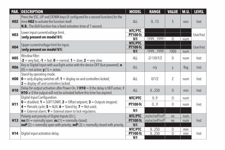
H02Press the ESC, UP and DOWN keys (if configured for a second function) for the time H02 to activate the function itself.N.B.: The AUX function has a fixed activation time of 1 second.
ALL 0...15 5 secs Inst
H03 Lower input current/voltage limit.(only present on model V/I)
NTC/PTCUser/InstPT100-Tc
V/I -1999...1999 0 num
H04 Upper current/voltage limit for input.(only present on model V/I)
NTC/PTCUser/InstPT100-Tc
V/I -1999...1999 1000 num
H05 Window filter:-2 = very fast; -1 = fast; 0 = normal; 1 = slow; 2 = very slow. ALL -2/-1/0/1/2 0 num Inst
H06 Key or Digital Input with aux/light active with the device OFF (but powered). n (0) = not active; y (1) = active. ALL n/y y flag Inst
H08Stand-by operating mode.0 = only display switches off; 1 = display on and controllers locked;2 = display off and controllers locked.
ALL 0/1/2 2 num Inst
H10 Delay for output activation after Power On. If H10 = 0 the delay is NOT active; if H10 ≠ 0 the output will not be activated before this time has expired. ALL 0...250 0 min Inst
H11
Digital Input Configuration.0 = disabled; 1 = SOFT START; 2 = Offset setpoint; 3 = Outputs stopped;4 = Periodic cycle; 5 = AUX; 6 = Stand-by; 7 = Not used;8 = External alarm; 9 = External alarm to lock regulators.
NTC/PTC 0..9 0 num
InstPT100-Tc 0...9 0 num
V/I
H13Polarity and priority of Digital Inputs (D.I.).no (0) = normally open; nc (1) = normally closed;noP (2) = normally open with priority; ncP (3) = normally closed with priority.
NTC/PTC no/nc/noP/ncP no numInstPT100-Tc no/nc/noP/ncP no num
V/I
H14 Digital input activation delay.NTC/PTC 0...250 0 min
InstPT100-Tc 0...250 0 minV/I

PAR. DESCRIPTION MODEL RANGE VALUE M.U. LEVEL
H21 Configuration of Digital Output1 (OUT1). 0 = disabled; 1 = on-off (controller 1)2 = on-off (controller 2); 3 = Alarm; 4 = Cyclic; 5 = Aux/Light; 6 = Stand-by. ALL 0...6 1 num Inst
H22 Configuration of Digital Output2 (OUT2). Same as H21. ALL 0...6 1 num Inst
H31Configuration of UP key.0 = disabled; 1 = SOFT START; 2 = Offset setpoint; 3 = Outputs stopped;4 = Periodic cycle; 5 = AUX output; 6 = Stand-by; 7 = not used.
ALL 0...7 0 num Inst
H32 Configuration of DOWN key. Same as H31. ALL 0...7 0 num InstH33 Configuration of ESC key. Same as H31. ALL 0...7 6 num InstrEL firmware version. Device software release: read-only parameter. ALL / / / User/InsttAb Parameters table. Reserved: read-only parameter. ALL / / / User
COPY CARD (folder ‘FPr’)UL Upload. Transfer of programming parameters from instrument to Copy Card. ALL / / / InstdL Download. Transfer of programming parameters from Copy Card to instrument. ALL / / / Inst
FrFormat. Cancels all data entered in the Copy Card.IMPORTANT: If parameter Fr (Copy Card formatting) is used, the data entered in the card will be permanently lost. This operation cannot be reversed.
ALL / / / Inst
FUNCTIONS (folder ‘FnC’)Function Function label ACTIVE Function label NOT ACTIVE D.I. KEY Alarm signalingSoft start SOn SOF 1 1 Flashing iconReduced setpoint OSP SP 2 2 ON IconActuations block bOn bOF 3 3 ON IconPeriodic cycle Con CoF 4 4 ON IconAUX AOn AOF 5 5 ON IconStand-by On OF 6 6 ON IconAlarm acknowledgement tAL tAL 7 7 ON IconNOTES: - to modify the status of a given function, press the ‘set’ key
- If the instrument is switched off, the function labels will return to the default status
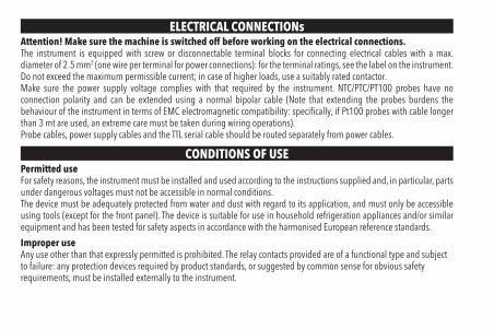
ELECTRICAL CONNECTIONsAttention! Make sure the machine is switched off before working on the electrical connections.The instrument is equipped with screw or disconnectable terminal blocks for connecting electrical cables with a max. diameter of 2.5 mm2 (one wire per terminal for power connections): for the terminal ratings, see the label on the instrument.Do not exceed the maximum permissible current; in case of higher loads, use a suitably rated contactor.Make sure the power supply voltage complies with that required by the instrument. NTC/PTC/PT100 probes have no connection polarity and can be extended using a normal bipolar cable (Note that extending the probes burdens the behaviour of the instrument in terms of EMC electromagnetic compatibility: specifically, if Pt100 probes with cable longer than 3 mt are used, an extreme care must be taken during wiring operations).Probe cables, power supply cables and the TTL serial cable should be routed separately from power cables.
CONDITIONS OF USEPermitted useFor safety reasons, the instrument must be installed and used according to the instructions supplied and, in particular, parts under dangerous voltages must not be accessible in normal conditions.The device must be adequately protected from water and dust with regard to its application, and must only be accessible using tools (except for the front panel). The device is suitable for use in household refrigeration appliances and/or similar equipment and has been tested for safety aspects in accordance with the harmonised European reference standards.
Improper useAny use other than that expressly permitted is prohibited. The relay contacts provided are of a functional type and subject to failure: any protection devices required by product standards, or suggested by common sense for obvious safety requirements, must be installed externally to the instrument.

LIABILITY AND RESIDUAL RISKSELIWELL CONTROLS SRL declines any liability for damage due to:
• installation/uses different from those specified and, in particular, not complying with the safety regulations and/or instructions given in this document;
• use on panels that do not provide adequate protection against electric shocks, water or dust when assembled;• use on panels allowing access to dangerous parts without the use of tools;• tampering with and/or modifying the product;• installation/use on panels not complying with current standards and regulations.
DISCLAIMERThis document is the exclusive property of ELIWELL CONTROLS SRL and may not be reproduced or circulated unless expressly authorised by ELIWELL CONTROLS SRL itself.Every care has been taken in preparing this document; nevertheless ELIWELL CONTROLS SRL cannot accept liability for any damage resulting from its use. The same applies to any person or company involved in preparing and editing this document. ELIWELL CONTROLS SRL reserves the right to make aesthetic or functional changes at any time without notice.
DISPOSALThe appliance (or the product) must be disposed of separately in compliance with the local standards in force on waste disposal.

Eliwell Controls s.r.l.Via dell’Industria, 15 - Z.I. Paludi32010 Pieve d’Alpago (BL) ITALYT: +39 0437 986 111F: +39 0437 989 066www.eliwell.com
Technical Customer Support:T: +39 0437 986 300E: [email protected]
SalesT: +39 0437 986 100 (Italy)T: +39 0437 986 200 (other countries)E: [email protected]
cod. 9IS44317-1 • ICPlus 915 • EN • rel. 10/14© Eliwell Controls s.r.l. 2014 • All rights reserved.


