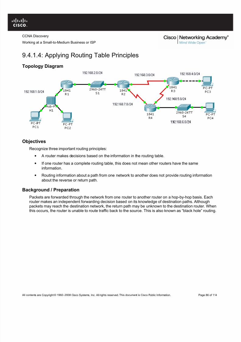
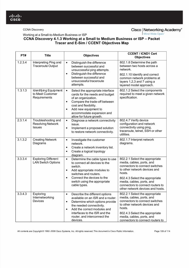
• Distinguish the difference between successful and unsuccessful ping attempts.
• Distinguish the difference between successful and unsuccessful traceroute attempts.
Background / Preparation
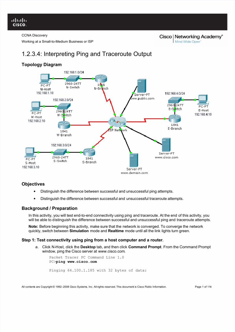
In this activity, you will test end-to-end connectivity using ping and traceroute. At the end of this activity, youwill be able to distinguish the difference between successful and unsuccessful ping and traceroute attempts.
Note: Before beginning this activity, make sure that the network is converged. To converge the networkquickly, switch between Simulation mode and Realtime mode until all the link lights turn green.
Step 1: Test connectivity using ping from a host computer and a router.
a. Click N-Host, click the Desktop tab, and then click Command Prompt. From the Command Promptwindow, ping the Cisco server at www.cisco.com.
Packet Tracer PC Command Line 1.0PC> ping www.cisco.com
Working at a Small-to-Medium Business or ISPRequest timed out.Reply from 64.100.1.185: bytes=32 time=185ms TTL=123Reply from 64.100.1.185: bytes=32 time=281ms TTL=123Reply from 64.100.1.185: bytes=32 time=287ms TTL=123
Ping statistics for 64.100.1.185:Packets: Sent = 4, Received = 3, Lost = 1 (25% loss),
Approximate round trip times in milli-seconds:Minimum = 185ms, Maximum = 287ms, Average = 251ms
PC>
b. From the output, you can see that N-Host was able to obtain an IP address for the Cisco server. TheIP address was obtained using (DNS). Also notice that the first ping failed. This failure is most likelydue to lack of ARP convergence between the source and destination. If you repeat the ping, you willnotice that all pings succeed.
c. From the Command Prompt window on N-Host, ping E-Host at 192.168.4.10. The pings fail. If you donot want to wait for all four unsuccessful ping attempts, press Ctrl+C to abort the command, asshown below.
PC> ping 192.168.4.10
Pinging 192.168.4.10 with 32 bytes of data:
Request timed out.Request timed out.
Ping statistics for 192.168.4.10:Packets: Sent = 3, Received = 0, Lost = 3 (100% loss),
Control-C^CPC>
d. Click the N-Branch router, and then click the CLI tab. Press Enter to get the router prompt. From therouter prompt, ping the Cisco server at www.cisco.com.
N-Branch> ping www.cisco.com Translating "www.cisco.com"...domain server (64.100.1.242)Type escape sequence to abort.Sending 5, 100-byte ICMP Echos to 64.100.1.185, timeout is 2 seconds:.!!!!Success rate is 80 percent (4/5), round-trip min/avg/max = 210/211/213
ms
N-Branch>
e. As you can see, the ping output on a router is different from a PC host. Notice that the N-Branchrouter resolved the domain name to the same IP address that N-Host used to send its pings. Alsonotice that the first ping fails, which is indicated by a period (.), and that the next four pings succeed,as shown with an exclamation point (!).
f. From the CLI tab on N-Branch, ping E-Host at 192.168.4.10. Again, the pings fail. To not wait for allthe failures, press Ctrl+C.
Working at a Small-to-Medium Business or ISPN-Branch> ping 192.168.4.10
Type escape sequence to abort.Sending 5, 100-byte ICMP Echos to 192.168.4.10, timeout is 2 seconds:...Success rate is 0 percent (0/4)
N-Branch>
Step 2: Test connectivity using traceroute from a host computer and a router.
a. Click N-Host, click the Desktop tab, and then click Command Prompt. From the Command Promptwindow, trace the route to the Cisco server at www.cisco.com.
PC>tracert www.cisco.com
Tracing route to 64.100.1.185 over a maximum of 30 hops:
1 92 ms 77 ms 86 ms 192.168.1.12 91 ms 164 ms 84 ms 64.100.1.1013 135 ms 168 ms 151 ms 64.100.1.64 185 ms 261 ms 161 ms 64.100.1.345 257 ms 280 ms 224 ms 64.100.1.626 310 ms 375 ms 298 ms 64.100.1.185
Trace complete.
PC>
g. The above output shows that you can successfully trace a route all the way to the Cisco server at64.100.1.185. Each hop in the path is a router responding three times to trace messages from N-Host. The trace continues until the destination for the trace (64.100.1.185) responds three times.
b. From the Command Prompt window on N-Host, trace a route to E-Host at 192.168.4.10. The tracefails, but notice that the tracert command traces up to 30 hops. If you do not want to wait for all 30attempts to time out, press Ctrl+C.
PC>tracert 192.168.4.10
Tracing route to 192.168.4.10 over a maximum of 30 hops:
1 103 ms 45 ms 91 ms 192.168.1.12 56 ms 110 ms 125 ms 64.100.1.101
3 174 ms 195 ms 134 ms 64.100.1.64 246 ms 183 ms 179 ms 64.100.1.345 217 ms 285 ms 226 ms 64.100.1.626 246 ms 276 ms 245 ms 64.100.1.1547 * * * Request timed out.8 * * * Request timed out.9 * * * Request timed out.10
The tracert command can be helpful in finding the potential source of a problem. The last device to
respond was 64.100.1.154, so you would start troubleshooting by determining which device isconfigured with the IP address 64.100.1.154. The source of the problem might not be that device, butthe trace has given you a starting point, whereas a ping simply tells you that the destination is either reachable or unreachable.
c. Click the N-Branch router, and then click the CLI tab. Press Enter to get the router prompt. From therouter prompt, trace the route to the Cisco server at www.cisco.com.
N-Branch>traceroute www.cisco.com Translating "www.cisco.com"...domain server (64.100.1.242)Type escape sequence to abort.Tracing the route to 64.100.1.185
As you can see, traceroute output on a router is very similar to the output on a PC host. The onlydifference is that on a PC host, the IP address is listed after the three millisecond outputs.
d. From the CLI tab on N-Branch, trace the route to E-Host at 192.168.4.10. The trace fails at the sameIP address as it failed when tracing from N-Host. Again, you can use Ctrl+C to abort the command.
N-Branch>traceroute 192.168.4.10Type escape sequence to abort.Tracing the route to 192.168.4.10
Step 3: Practice the ping and trace route commands.
Throughout this course, you will often use ping and traceroute to test connectivity and troubleshoot problems.To practice these commands, ping and trace from W-Host and S-Host to any other destination in the network.You can also ping and trace from N-Branch to other locations.
1.3.1.3: Identifying Equipment to Meet Customer Requirements
Topology Diagram
Objectives
• Select the appropriate interface cards for the needs and budget of an organization.
• Compare the trade-off between cost and flexibility.
• Add new equipment to accommodate expansion and allow for future growth.
Background / Preparation
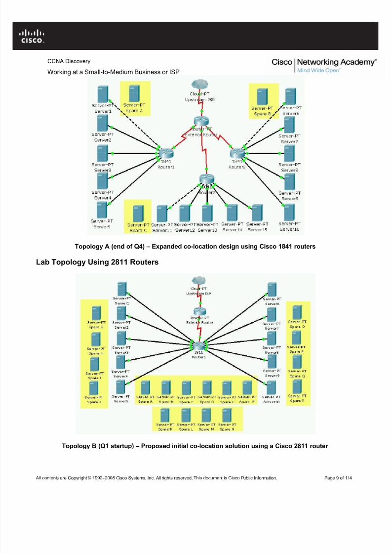
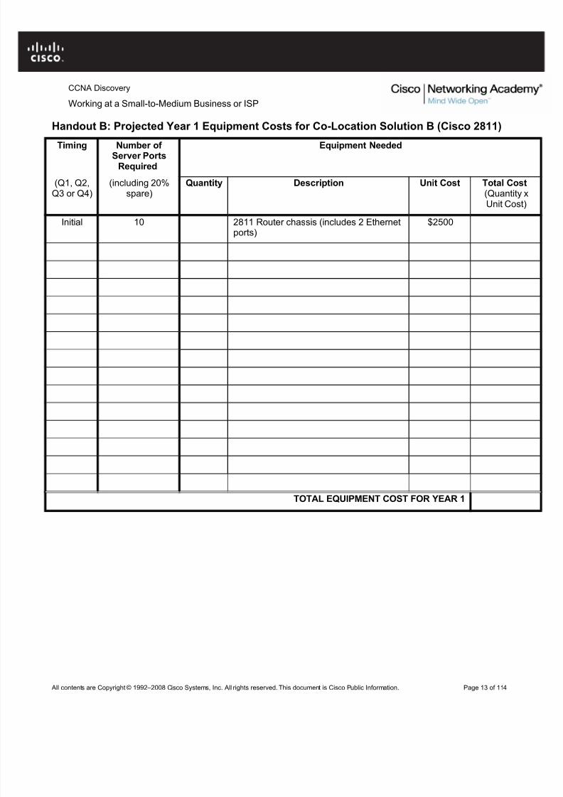
An owner of a small Tier 3 ISP provides Internet access to small businesses in the area. Ten customers arestarting e-commerce activities and have enquired about co-locating their web servers in the NOC facilities toprovide faster access to the Internet backbone via the upstream provider. Because of the growing trendtoward e-commerce, the ISP owner has decided to add co-location services to the services that they offer.
To connect customer web servers to the Internet, the ISP must purchase new routers. The ISP is decidingbetween using several less-expensive Cisco 1841 routers or one or two of the larger Cisco 2811 routers. You
have been asked to evaluate which router model best meets the needs of the proposed co-location servicesand how many routers and interface cards are needed. The following requirements must be met:
• The maximum budget for routers and interface cards is $10,000 for the first year.
• The starting configuration must support 10 customer servers.
• At least 20% spare capacity must be available at all times. If the spare capacity falls below 20%, newequipment should be purchased.
• A 20% growth rate in the demand for co-location services is expected each quarter (every threemonths).
• Two serial ports must be available to connect to the upstream ISP. To ensure that backup routes areavailable, each router needs to have its own connection to the upstream provider.
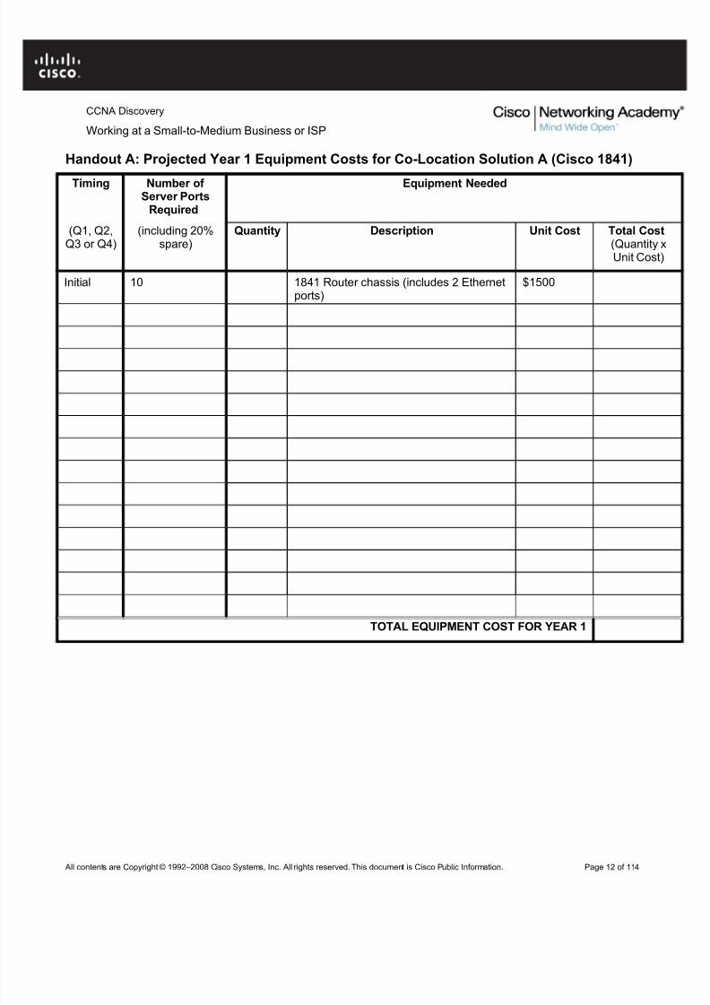
Your task is to recommend the solution that best meets the requirements for the first year while staying withinthe maximum budget of $10,000. For the purposes of this exercise, use the following equipment costs.
Working at a Small-to-Medium Business or ISPNote: This activity begins by showing 100% completion, because the purpose is to only demonstrate theprocess used to design and plan a network upgrade. This activity is not graded.
Step 1: Evaluate the scalability of the Cisco 1841 router.
a. Click the 1841 router in the workspace area.
b. On the Physical tab, in the Physical Device View window, click the power switch to turn off the router.
c. Click each module in the Modules column and read its description in the box below the router.
d. Which module provides the most Ethernet ports? How many ports does it have?
l. Fill out the expense sheet in Handout A with the necessary equipment and costs for each quarter of operation, assuming a 20% growth every quarter. (Hint: Round up to the nearest whole number. For example, if a 20% growth is 2.4 servers, plan to support 3 new servers.)
m. Based on your expense sheet calculations, how soon will another 1841 router need to be purchased?
e. Drag the network module with the most Ethernet ports to the empty network module slot on the router in the Physical Device View window. The network module slot is the larger slot on the left side of therouter.
f. How many empty interface card slots (smaller slots) are available? (Write your answer on thehandout.)
j. Drag the interface card with the most serial ports to the empty slot on the router.
k. The 2811 router comes with two Fast Ethernet ports, in addition to the ports provided by the modules. Assuming one Ethernet port is used per customer server, what is the maximum number of serversthat one 2811 router can support with the added modules?
p. Fill out the expense sheet in Handout B with the necessary equipment and costs for each quarter of
operation, assuming a 20% growth every quarter. (Hint: Round up to the nearest whole number. For example, if a 20% growth is 2.4 servers, plan to support 3 new servers.)
q. Based on your expense sheet calculations, how soon will another 2811 router need to be purchased?
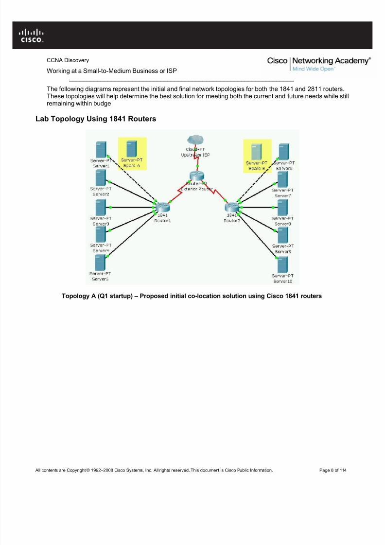
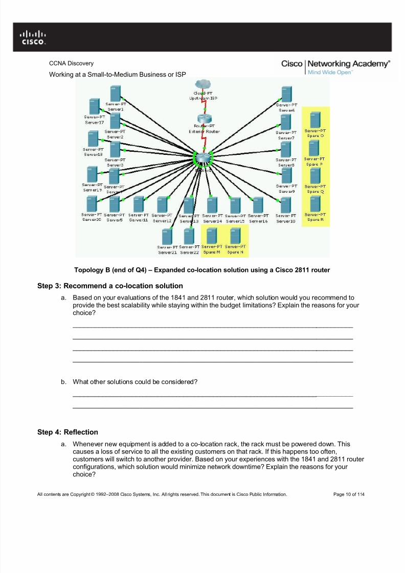
Topology B (end of Q4) – Expanded co-location solution using a Cisco 2811 router
Step 3: Recommend a co-location solution
a. Based on your evaluations of the 1841 and 2811 router, which solution would you recommend toprovide the best scalability while staying within the budget limitations? Explain the reasons for your choice?
a. Whenever new equipment is added to a co-location rack, the rack must be powered down. Thiscauses a loss of service to all the existing customers on that rack. If this happens too often,customers will switch to another provider. Based on your experiences with the 1841 and 2811 router configurations, which solution would minimize network downtime? Explain the reasons for your choice?
b. Network availability and reliability is of great importance to e-commerce businesses. What wouldhappen to the Internet access of the customer web servers if one of the routers in the co-locationnetwork failed? Which solution would negatively affect the most customers if a co-location router failed?
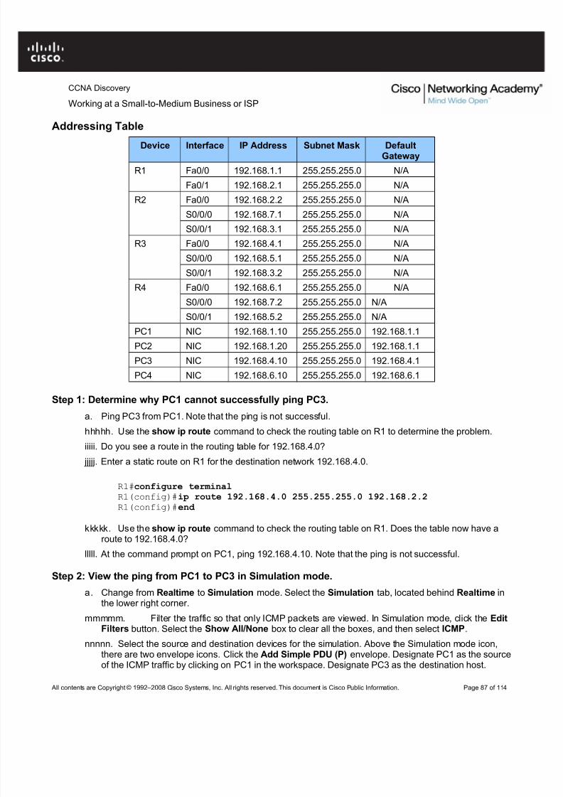
2.3.1.4: Troubleshooting and Resolving Network Issues
Topology Diagram
Objectives
• Diagnose a network connectivity issue.
• Implement a proposed solution to restore network connectivity.
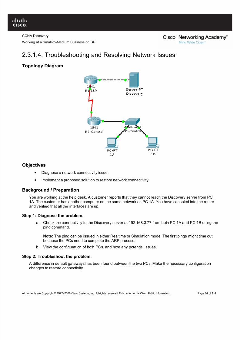
Background / Preparation
You are working at the help desk. A customer reports that they cannot reach the Discovery server from PC1A. The customer has another computer on the same network as PC 1A. You have consoled into the router and verified that all the interfaces are up.
Step 1: Diagnose the problem.
a. Check the connectivity to the Discovery server at 192.168.3.77 from both PC 1A and PC 1B using theping command.
Note: The ping can be issued in either Realtime or Simulation mode. The first pings might time outbecause the PCs need to complete the ARP process.
b. View the configuration of both PCs, and note any potential issues.
Step 2: Troubleshoot the problem.
A difference in default gateways has been found between the two PCs. Make the necessary configurationchanges to restore connectivity.
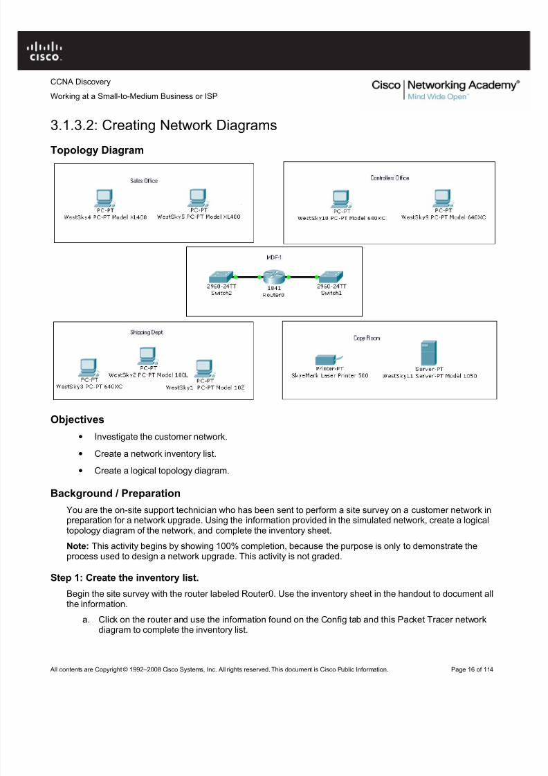
You are the on-site support technician who has been sent to perform a site survey on a customer network inpreparation for a network upgrade. Using the information provided in the simulated network, create a logicaltopology diagram of the network, and complete the inventory sheet.
Note: This activity begins by showing 100% completion, because the purpose is only to demonstrate theprocess used to design a network upgrade. This activity is not graded.
Step 1: Create the inventory list.
Begin the site survey with the router labeled Router0. Use the inventory sheet in the handout to document allthe information.
a. Click on the router and use the information found on the Config tab and this Packet Tracer networkdiagram to complete the inventory list.
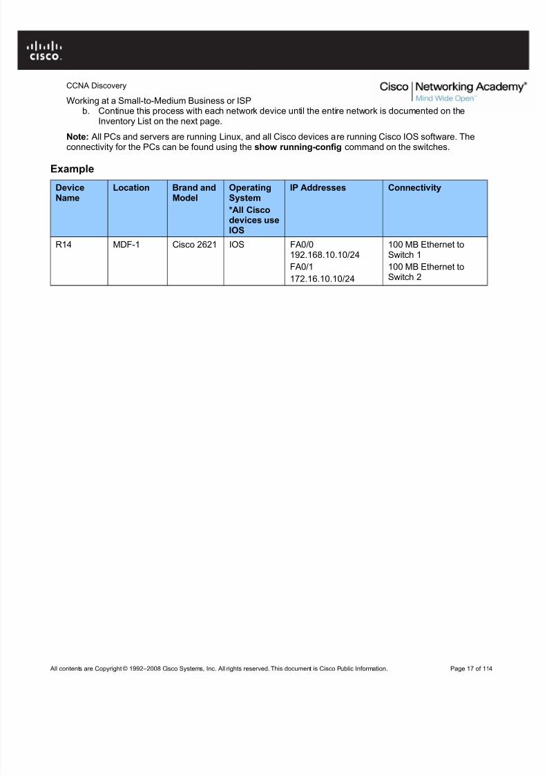
Working at a Small-to-Medium Business or ISPb. Continue this process with each network device until the entire network is documented on the
Inventory List on the next page.
Note: All PCs and servers are running Linux, and all Cisco devices are running Cisco IOS software. Theconnectivity for the PCs can be found using the show running-config command on the switches.
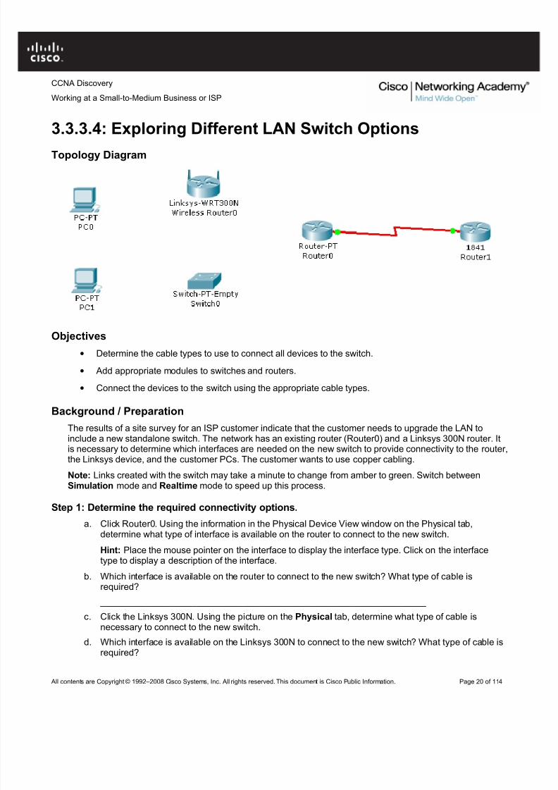
• Determine the cable types to use to connect all devices to the switch.
• Add appropriate modules to switches and routers.
• Connect the devices to the switch using the appropriate cable types.
Background / PreparationThe results of a site survey for an ISP customer indicate that the customer needs to upgrade the LAN toinclude a new standalone switch. The network has an existing router (Router0) and a Linksys 300N router. Itis necessary to determine which interfaces are needed on the new switch to provide connectivity to the router,the Linksys device, and the customer PCs. The customer wants to use copper cabling.
Note: Links created with the switch may take a minute to change from amber to green. Switch betweenSimulation mode and Realtime mode to speed up this process.
Step 1: Determine the required connectivity options.
a. Click Router0. Using the information in the Physical Device View window on the Physical tab,determine what type of interface is available on the router to connect to the new switch.
Hint: Place the mouse pointer on the interface to display the interface type. Click on the interfacetype to display a description of the interface.
b. Which interface is available on the router to connect to the new switch? What type of cable isrequired?
Working at a Small-to-Medium Business or ISP ________________________________________________________________
Step 2: Configure the new switch with the required options.a. Click Switch0.
b. On the Physical tab, explore each switch module available under the Modules option.
c. Choose the appropriate interfaces to connect to Router0 and the Linksys 300N router.
d. Choose the appropriate interfaces to connect to the existing PCs.
e. Power down the switch using the power button in the Physical Device View window on the Physicaltab.
f. Choose the appropriate modules for the switch. Add the four necessary interfaces to the switch.
g. Power up the switch using the power button shown in the Physical Device View window on thePhysical tab.
h. Click the Config tab. Select each interface and ensure that the On box is checked.
Step 3: Connect the router to the switch.
a. Using the appropriate cable, connect the router port to the first available switch port. Click the Config tab on the router. Select the interface and ensure that the On box is checked.
b. Verify connectivity. A green light appears on each end of the link if the cabling is correct.
Step 4: Connect the Linksys 300N to the switch.
a. Using the appropriate cable, connect the Linksys 300N to the second available port on the newswitch.
b. Verify connectivity. A green light appears on each end of the link if the cabling is correct.
Step 5: Connect the PCs to the switch.
a. Using the appropriate cable, connect the existing PCs to the new switch.
b. Verify connectivity. A green light appears on each end of the links if the cabling is correct.
c. Click the Check Results button at the bottom of this instruction window to check your work.
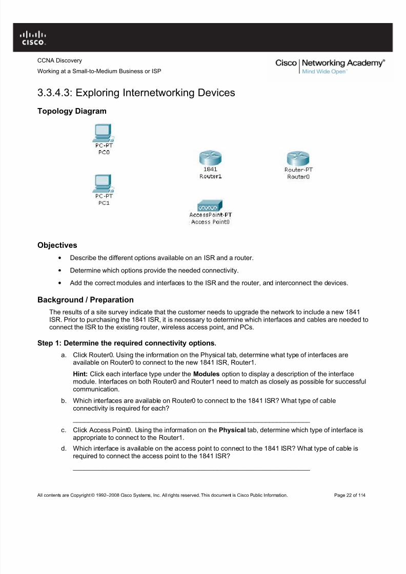
• Describe the different options available on an ISR and a router.
• Determine which options provide the needed connectivity.
• Add the correct modules and interfaces to the ISR and the router, and interconnect the devices.
Background / PreparationThe results of a site survey indicate that the customer needs to upgrade the network to include a new 1841ISR. Prior to purchasing the 1841 ISR, it is necessary to determine which interfaces and cables are needed toconnect the ISR to the existing router, wireless access point, and PCs.
Step 1: Determine the required connectivity options.
a. Click Router0. Using the information on the Physical tab, determine what type of interfaces areavailable on Router0 to connect to the new 1841 ISR, Router1.
Hint: Click each interface type under the Modules option to display a description of the interfacemodule. Interfaces on both Router0 and Router1 need to match as closely as possible for successfulcommunication.
b. Which interfaces are available on Router0 to connect to the 1841 ISR? What type of cableconnectivity is required for each?
c. Click Access Point0. Using the information on the Physical tab, determine which type of interface isappropriate to connect to the Router1.
d. Which interface is available on the access point to connect to the 1841 ISR? What type of cable isrequired to connect the access point to the 1841 ISR?
Working at a Small-to-Medium Business or ISPHint: The access point is a similar type of device to the router and requires the same type of cableused to connect like devices.
Step 2: Configure the new 1841 ISR, Router 1, with the required options.
a. Click Router1. Explore the ISR modules available under the Modules option on the Physical tab.
b. Find the appropriate interface modules to connect to Router0, Access Point0, and the existing PCs.
Note: The module names might not be the same as those installed on the existing networkingequipment. Choose modules that provide the same kind of connectivity, and use the same type of cable.
c. What types of interface modules are available for the 1841 ISR? Which Ethernet or serial interfacesare built into the 1841 ISR?
For this network, the multiport switch module is the best choice to connect the PCs. The built-in LANports can be used to connect to the access point.
d. Power down the 1841 ISR using the power button in the Physical Device View window on thePhysical tab.
e. Add the appropriate modules to the 1841 ISR. Place the module that connects to Router0 in the sloton the right (Slot 0), and place the multiport switch module in the slot on the left (Slot 1).
Note: The modules can be used in either slot. However, to ensure correct grading in Packet Tracer place the modules as instructed.
f. Power up the 1841 ISR using the power button in the Physical Device View window on the Physicaltab.
g. Go to the Config tab and select each interface. Check the On box to power up the interfaces.
h. Ensure that all interfaces are on.
Step 3: Connect Router0 to the 1841 ISR, Router1.
a. Router0 connects Router1 over a wide area network. Using the appropriate cable, connect the firstappropriate Router0 port to the first available Router1 port.
b. Verify that the connection is working. A green link light at each end of the cable indicates that thecorrect cable type is being used and that the interfaces are powered up.
Step 4: Connect the access point to the 1841 ISR, Router 1.
a. Using the appropriate cable, connect the access point to the 1841 ISR. Connect the access point tothe first built-in LAN port on the 1841 ISR.
b. Verify that the connection is working. A green link light at each end of the cable indicates that thecorrect cable type is being used and that the interfaces are powered up.
Step 5: Connect the PCs to the 1841 ISR.
a. Using the appropriate cable, connect the existing PCs to the new 1841 ISR. Connect PC0 to the firstport on the four-port switch module. It appears in the interface list as FastEthernet 0/1/0. ConnectPC1 to the second port.
Note: The built-in Fast Ethernet LAN interfaces (Fast Ethernet 0/0 and Fast Ethernet 0/1) on the 1841ISR are not appropriate for connecting individual PCs.
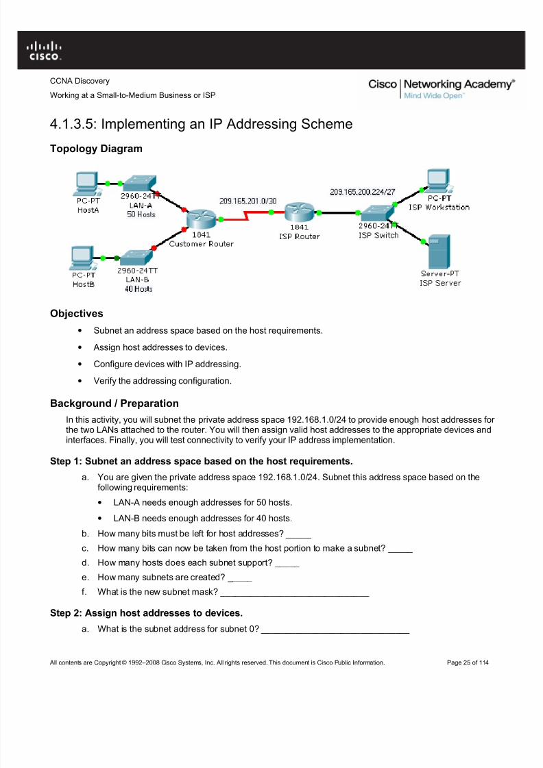
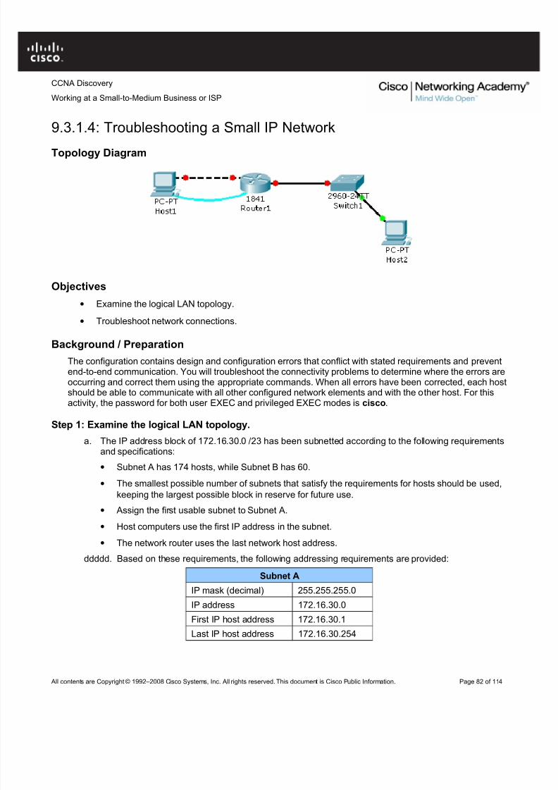
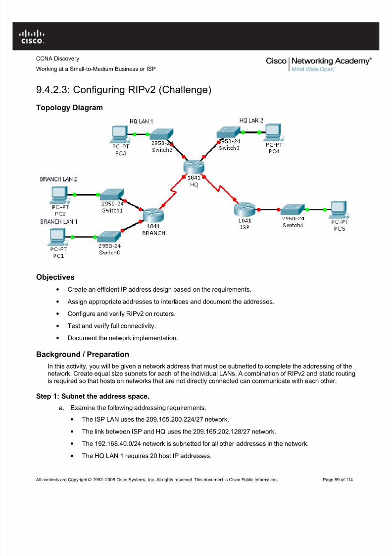
• Subnet an address space based on the host requirements.
• Assign host addresses to devices.
• Configure devices with IP addressing.
• Verify the addressing configuration.
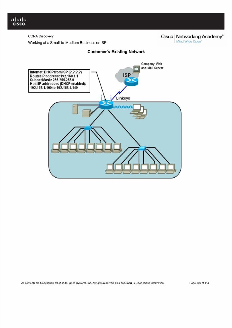
Background / PreparationIn this activity, you will subnet the private address space 192.168.1.0/24 to provide enough host addresses for the two LANs attached to the router. You will then assign valid host addresses to the appropriate devices andinterfaces. Finally, you will test connectivity to verify your IP address implementation.
Step 1: Subnet an address space based on the host requirements.
a. You are given the private address space 192.168.1.0/24. Subnet this address space based on thefollowing requirements:
• LAN-A needs enough addresses for 50 hosts.
• LAN-B needs enough addresses for 40 hosts.
b. How many bits must be left for host addresses? _____ c. How many bits can now be taken from the host portion to make a subnet? _____
d. How many hosts does each subnet support? _____
e. How many subnets are created? _____
f. What is the new subnet mask? ______________________________
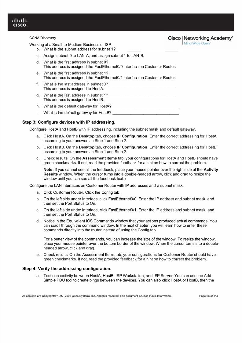
Step 2: Assign host addresses to devices.
a. What is the subnet address for subnet 0? ______________________________
Working at a Small-to-Medium Business or ISPb. What is the subnet address for subnet 1? ______________________________
c. Assign subnet 0 to LAN-A, and assign subnet 1 to LAN-B.
d. What is the first address in subnet 0? ______________________________ This address is assigned the FastEthernet0/0 interface on Customer Router.
e. What is the first address in subnet 1? ______________________________ This address is assigned the FastEthernet0/1 interface on Customer Router.
f. What is the last address in subnet 0? ______________________________ This address is assigned to HostA.
g. What is the last address in subnet 1? ______________________________ This address is assigned to HostB.
h. What is the default gateway for HostA? ______________________________
i. What is the default gateway for HostB? ______________________________
Step 3: Configure devices with IP addressing.
Configure HostA and HostB with IP addressing, including the subnet mask and default gateway.
a. Click HostA. On the Desktop tab, choose IP Configuration. Enter the correct addressing for HostAaccording to your answers in Step 1 and Step 2.
b. Click HostB. On the Desktop tab, choose IP Configuration. Enter the correct addressing for HostBaccording to your answers in Step 1 and Step 2.
c. Check results. On the Assessment Items tab, your configurations for HostA and HostB should havegreen checkmarks. If not, read the provided feedback for a hint on how to correct the problem.
Note: If you cannot see all the feedback, place your mouse pointer over the right side of the ActivityResults window. When the cursor turns into a double-headed arrow, click and drag to resize the
window until you can see all the feedback text.)Configure the LAN interfaces on Customer Router with IP addresses and a subnet mask.
a. Click Customer Router. Click the Config tab.
b. On the left side under Interface, click FastEthernet0/0. Enter the IP address and subnet mask, andthen set the Port Status to On.
c. On the left side under Interface, click FastEthernet0/1. Enter the IP address and subnet mask, andthen set the Port Status to On.
d. Notice in the Equivalent IOS Commands window that your actions produced actual commands. Youcan scroll through the command window. In the next chapter, you will learn how to enter thesecommands directly into the router instead of using the Config tab.
For a better view of the commands, you can increase the size of the window. To resize the window,place your mouse pointer over the bottom border of the window. When the cursor turns into a double-headed arrow, click and drag.
e. Check results. On the Assessment Items tab, your configurations for Customer Router should havegreen checkmarks. If not, read the provided feedback for a hint on how to correct the problem.
Step 4: Verify the addressing configuration.
a. Test connectivity between HostA, HostB, ISP Workstation, and ISP Server. You can use the AddSimple PDU tool to create pings between the devices. You can also click HostA or HostB, then the
Working at a Small-to-Medium Business or ISPDesktop tab, and then Command Prompt. Use the ping command to test connectivity to other devices. To obtain the IP address of another device, place your mouse pointer over the device.
b. Check results. On the Connectivity Tests tab, the status of each test should be successful.
Reflection
a. How many subnets are still available for future expansion?
b. What would be the two subnet addresses if the host requirement was 80 hosts per LAN?
c. Challenge: Create your own Packet Tracer network using the same topology, but implement anaddressing scheme based on 80 hosts per LAN. Have another student or your instructor check your work.
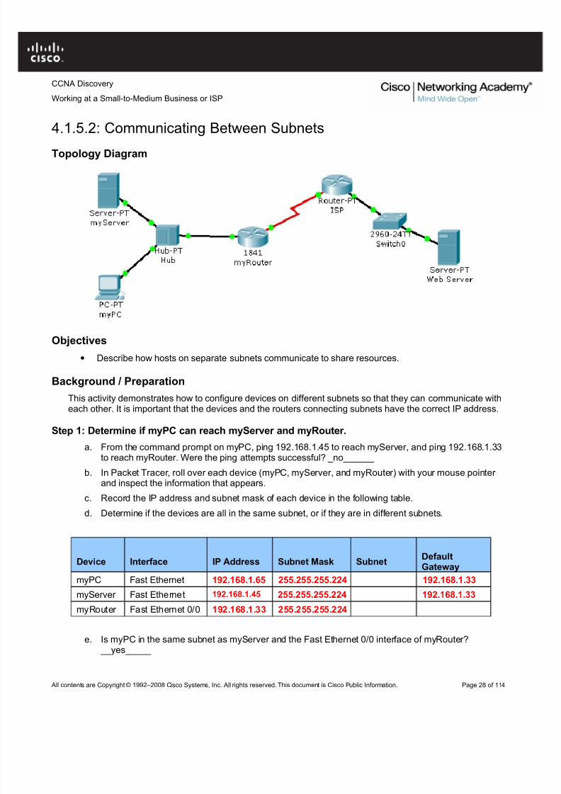
• Describe how hosts on separate subnets communicate to share resources.
Background / Preparation
This activity demonstrates how to configure devices on different subnets so that they can communicate witheach other. It is important that the devices and the routers connecting subnets have the correct IP address.
Step 1: Determine if myPC can reach myServer and myRouter.
a. From the command prompt on myPC, ping 192.168.1.45 to reach myServer, and ping 192.168.1.33to reach myRouter. Were the ping attempts successful? _no______
b. In Packet Tracer, roll over each device (myPC, myServer, and myRouter) with your mouse pointer and inspect the information that appears.
c. Record the IP address and subnet mask of each device in the following table.
d. Determine if the devices are all in the same subnet, or if they are in different subnets.
Device Interface IP Address Subnet Mask Subnet DefaultGateway
myPC Fast Ethernet 192.168.1.65 255.255.255.224 192.168.1.33
myServer Fast Ethernet 192.168.1.45 255.255.255.224 192.168.1.33
myRouter Fast Ethernet 0/0 192.168.1.33 255.255.255.224
e. Is myPC in the same subnet as myServer and the Fast Ethernet 0/0 interface of myRouter? __yes_____
Working at a Small-to-Medium Business or ISPStep 2: Configure the network to allow myPC to reach myServer.
On the Config tab on myPC, assign the second usable address in the subnet used for the LAN supported by
myRouter to myPC.
Step 3: Verify connectivity.
a. After changing the IP address on myPC, ping 192.168.1.45 to reach myServer, and ping192.168.1.33 to reach myRouter. The pings should be successful.
b. Click the Check Results button at the bottom of this instruction window to check your work.
Reflection
a. Why was myPC unable to communicate with myServer at the beginning of this activity?No
b. This exercise demonstrates how subnetting affects which devices cancommunicate on a network. What does this mean for IP address planning whenupgrading a network?
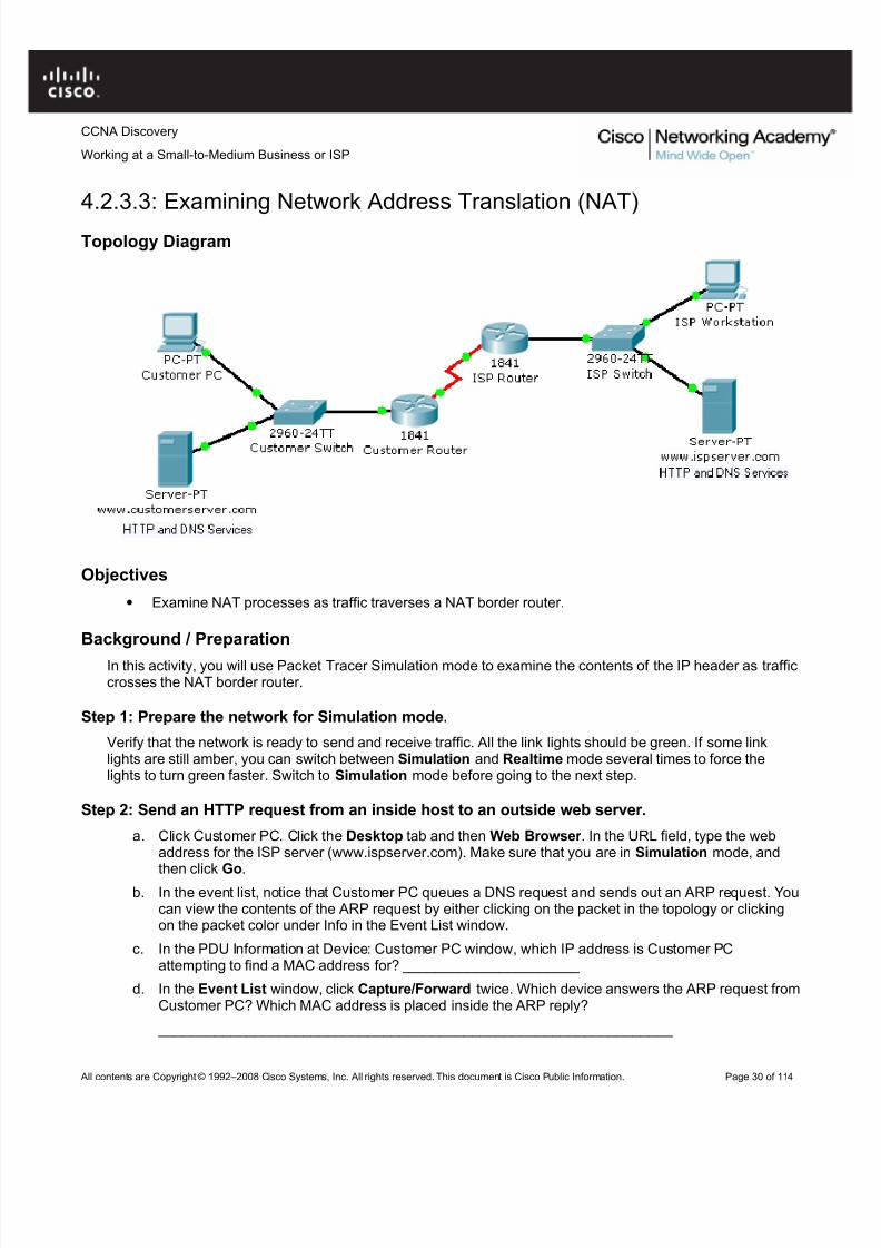
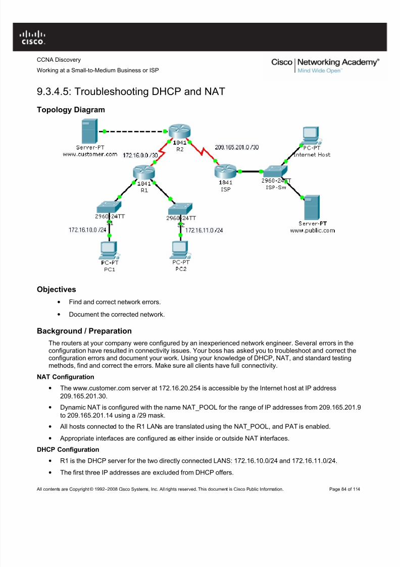
• Examine NAT processes as traffic traverses a NAT border router.
Background / Preparation
In this activity, you will use Packet Tracer Simulation mode to examine the contents of the IP header as trafficcrosses the NAT border router.
Step 1: Prepare the network for Simulation mode.
Verify that the network is ready to send and receive traffic. All the link lights should be green. If some linklights are still amber, you can switch between Simulation and Realtime mode several times to force thelights to turn green faster. Switch to Simulation mode before going to the next step.
Step 2: Send an HTTP request from an inside host to an outside web server.
a. Click Customer PC. Click the Desktop tab and then Web Browser . In the URL field, type the webaddress for the ISP server (www.ispserver.com). Make sure that you are in Simulation mode, and
then click Go.b. In the event list, notice that Customer PC queues a DNS request and sends out an ARP request. You
can view the contents of the ARP request by either clicking on the packet in the topology or clickingon the packet color under Info in the Event List window.
c. In the PDU Information at Device: Customer PC window, which IP address is Customer PCattempting to find a MAC address for? ______________________
d. In the Event List window, click Capture/Forward twice. Which device answers the ARP request fromCustomer PC? Which MAC address is placed inside the ARP reply?
Working at a Small-to-Medium Business or ISPe. In the Event List window, click Capture/Forward twice. Customer PC accepts the ARP replay and
then builds another packet. What is the protocol for this new packet? If you click Outbound PDU
Details for this packet, you can see the details of the protocol. _________ f. In the Event List window, click Capture/Forward twice. Click the packet at the
www.customerserver.com server. Then click the Outbound PDU Details tab. Scroll down to thebottom to see the Application Layer data. What is the IP address for the ISP server?
h. In the Event List window, click Capture/Forward 10 times until Customer PC formulates an HTTPrequest packet. Customer PC finally has enough information to request a web page from the ISPserver.
i. In the Event List window, click Capture/Forward three times. Click the packet at Customer Router toexamine the contents. Customer Router is a NAT border router. What is the inside local address andthe inside global address for Customer PC?
j. In the Event List window, click Capture/Forward seven times until the HTTP reply reachesCustomer Router. Examine the contents of the HTTP reply and notice that the inside local and globaladdresses have changed again as the packet is forwarded on to Customer PC.
Step 3: Send an HTTP request from an outside host to an inside web server.
Customer Server provides web services to the public (outside addresses) through the domain namewww.customerserver.com. Follow a process similar to Step 2 to observe an HTTP request on ISPWorkstation.
a. Click ISP Workstation. Click the Desktop tab, and then Web Browser . In the URL field, type theCustomer Server web address (www.customerserver.com). Make sure that you are in Simulationmode, and then click Go.
b. You can either click Auto Capture/Play or Capture/Forward to step through each stage of theprocess. The same ARP and DNS processes occur before the ISP Workstation can formulate anHTTP request.
c. When the HTTP request arrives at Customer Router, check the packet contents. What is the insidelocal address? What is the inside global address?
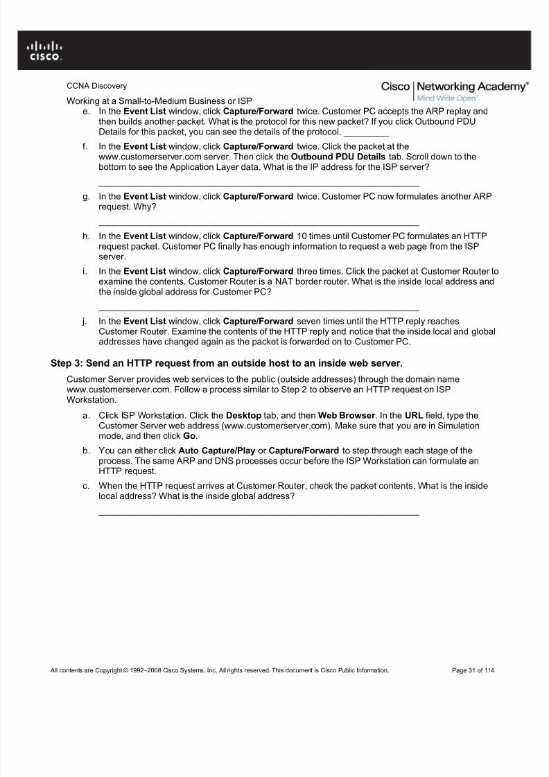
• Use the Cisco IOS CLI context-sensitive Help feature.
• Explore command shortcuts.
• Learn about error detection features.
• Use command history.
Background / Preparation
The Cisco IOS CLI includes many features that help in recalling commands and getting information aboutcommand use and function. In this activity, you will explore some of these features and perhaps discover whynetwork technicians prefer the Cisco IOS CLI.
Note: This activity begins by showing 100% completion, because the purpose is only to explore the CiscoIOS CLI. This activity is not graded.
Step 1: Connect to the Customer Cisco 1841 router.
Use the terminal emulation software on Customer PC to connect to the Cisco 1841 Customer Router. PressEnter to get started. The CustomerRouter> prompt indicates that you are in user EXEC mode.
Step 2: Explore the context-sensitive Help feature.
a. At the router command prompt, type ?. A brief description of the help that is available is displayed.
b. Type e? to see which commands start with the letter “e”.
c. Type en?. Notice that you see only commands that start with “en”.
d. Type enable. The prompt changes to CustomerRouter#, indicating that you are in privileged EXECmode.
Step 3: Explore Cisco IOS command shortcuts.
If you type letters that are unique to a command and then press the Tab key, the CLI automatically spells outthe complete command.
a. Type c at the CustomerRouter# prompt and press the Tab key. Because “c” by itself is not unique to just one command, nothing happens.
b. Now add “onf” to the “c” and press the Tab key. Because this sequence of letters is unique to theconfigure command, the CLI automatically completes the command entry.
Working at a Small-to-Medium Business or ISPc. Now type ? after “configure”. A list of parameters and options for the configure command are
displayed. The <cr> at the end of the output indicates that there are no other parameters that can be
added to the configure command in this mode. In this example, the CLI shows that you can useterminal with the configure command: configure terminal.
Step 4: Explore error detection features.
a. At the CustomerRouter# prompt, type con and then press Enter . The output % Ambiguouscommand: "con" indicates that this is an incomplete command.
b. At the router command prompt, enter configure trminal and then press Enter . Be sure to enter thecommand with the spelling error. The Cisco IOS CLI does not recognize the command and indicatesan error with the marker ^.
Step 5: Recall previously typed commands.
a. Previously used commands are stored in a history buffer. To recall the last command entered, press
Ctrl-P. The command appears at the router command prompt.
b. Scroll back through the commands in the history buffer by repeatedly pressing Ctrl-P, and then pressCtrl-N to cycle forward through the history buffer. The Up and Down Arrow keys can also be used torecall commands from the history buffer.
c. To view the last 10 commands entered, enter the show history command.
Reflection
a. List two Cisco IOS CLI commands that are available from the CustomerRouter# prompt but that arenot available from the CustomerRouter> prompt.
Tip: Type enable to change to the CustomerRouter# prompt, and type disable to return to the
CustomerRouter> prompt.b. What does <cr> indicate at the end of a list of commands after you have requested help?
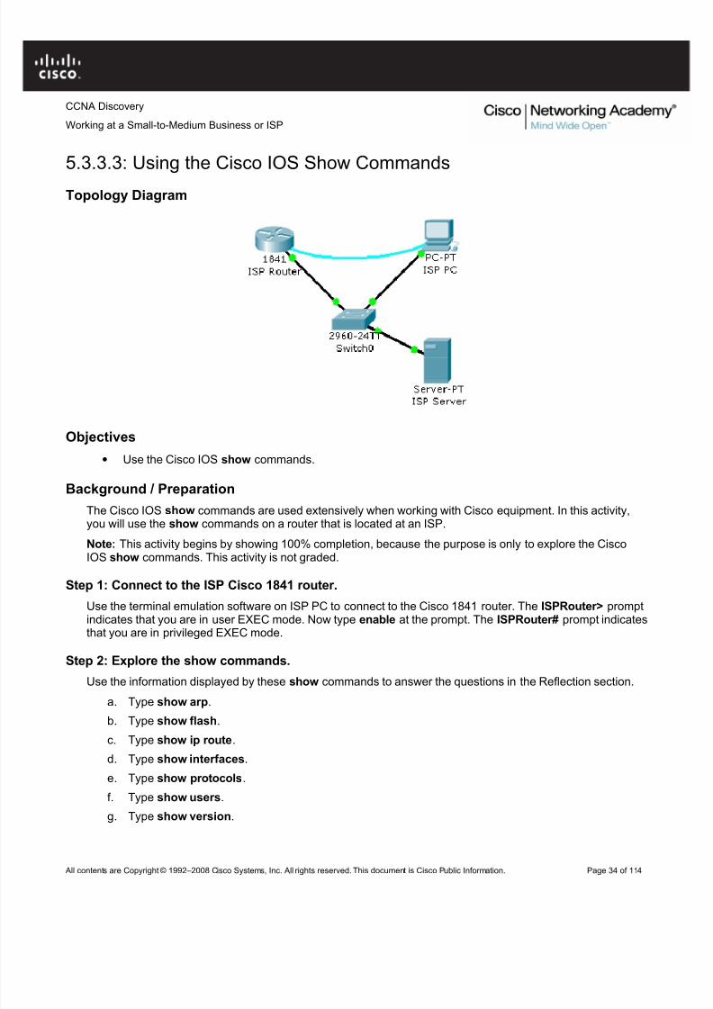
The Cisco IOS show commands are used extensively when working with Cisco equipment. In this activity,you will use the show commands on a router that is located at an ISP.
Note: This activity begins by showing 100% completion, because the purpose is only to explore the CiscoIOS show commands. This activity is not graded.
Step 1: Connect to the ISP Cisco 1841 router.
Use the terminal emulation software on ISP PC to connect to the Cisco 1841 router. The ISPRouter> promptindicates that you are in user EXEC mode. Now type enable at the prompt. The ISPRouter# prompt indicatesthat you are in privileged EXEC mode.
Step 2: Explore the show commands.
Use the information displayed by these show commands to answer the questions in the Reflection section.
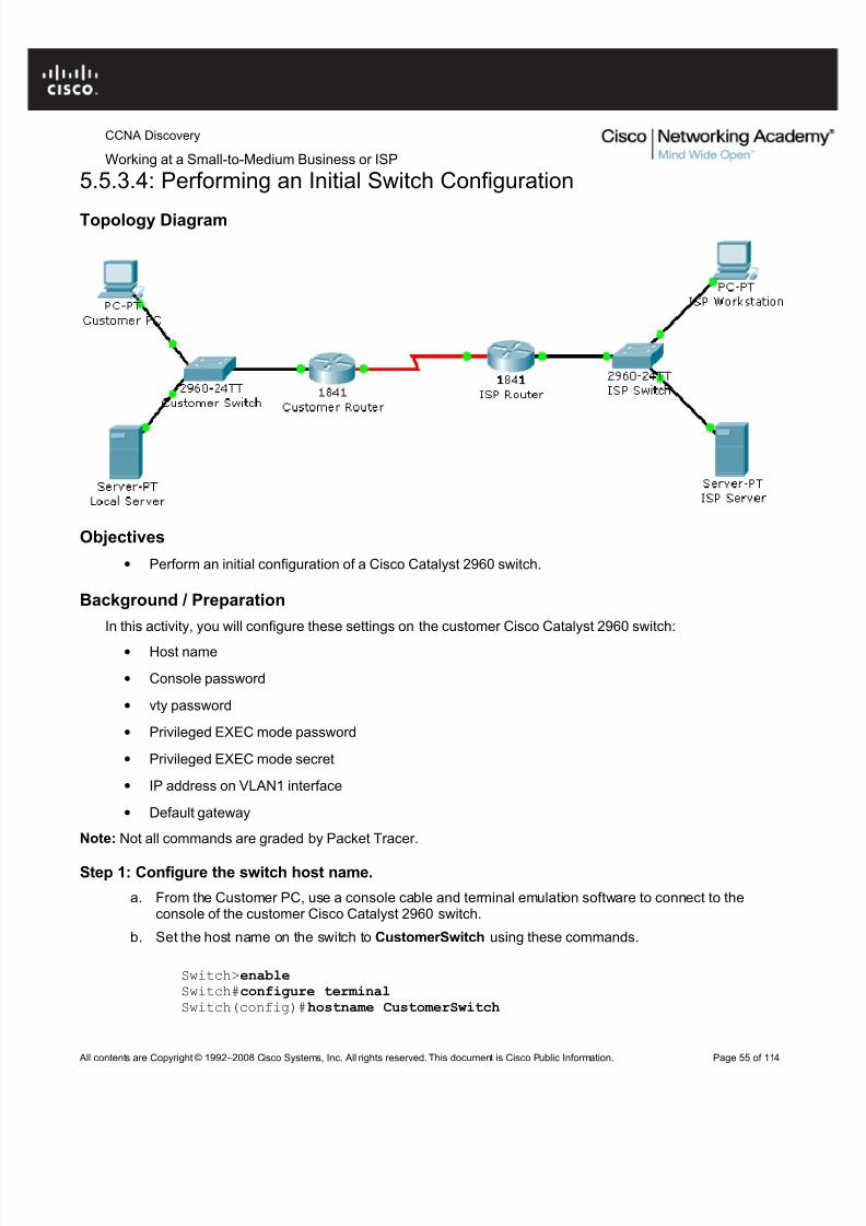
5.3.4.4: Performing an Initial Router Configuration
Topology Diagram
Objectives
• Configure the router host name.
• Configure passwords.
• Configure banner messages.
• Verify the router configuration.
Background / Preparation
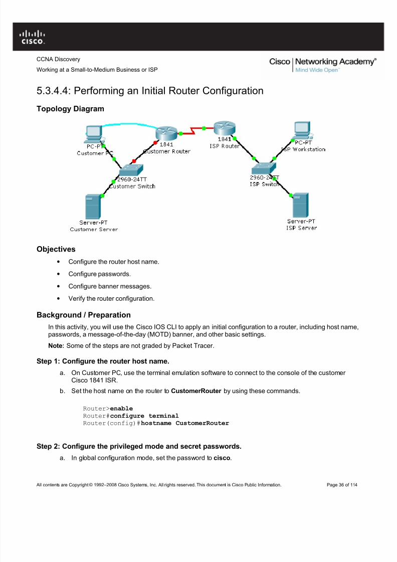
In this activity, you will use the Cisco IOS CLI to apply an initial configuration to a router, including host name,passwords, a message-of-the-day (MOTD) banner, and other basic settings.
Note: Some of the steps are not graded by Packet Tracer.
Step 1: Configure the router host name.
a. On Customer PC, use the terminal emulation software to connect to the console of the customer Cisco 1841 ISR.
b. Set the host name on the router to CustomerRouter by using these commands.
Step 5: Configure password encryption, a MOTD banner, and turn off domain server lookup.
a. Currently, the line passwords and the enable password are shown in clear text when you show therunning configuration. Verify this now by entering the show running-config command.
To avoid the security risk of someone looking over your shoulder and reading the passwords, encryptall clear text passwords.
c. Test the banner and passwords. Log out of the router by typing the exit command twice. The banner
displays before the prompt for a password. Enter the password to log back into the router.d. You may have noticed that when you enter a command incorrectly at the user or privileged EXEC
prompt, the router pauses while trying to locate an IP address for the mistyped word you entered. For example, this output shows what happens when the enable command is mistyped.
CustomerRouter>emableTranslating "emable"...domain server (255.255.255.255)
To prevent this from happening, use the following command to stop all DNS lookups from the router CLI.
CustomerRouter(config)#no ip domain-lookup
e. Save the running configuration to the startup configuration.
CustomerRouter(config)#end CustomerRouter#copy run start
Step 6: Verify the configuration.
a. Log out of your terminal session with the Cisco 1841 customer router.
b. Log in to the Cisco 1841 Customer Router. Enter the console password when prompted.
c. Navigate to privileged EXEC mode. Enter the privileged EXEC password when prompted.
d. Click the Check Results button at the bottom of this instruction window to check your work.
Reflection
e. Which Cisco IOS CLI commands did you use most?
f. How can you make the customer router passwords more secure?
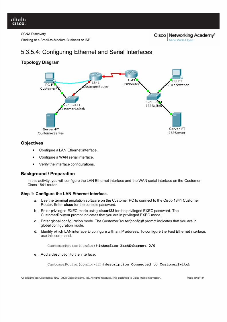
5.3.5.4: Configuring Ethernet and Serial Interfaces
Topology Diagram
Objectives
• Configure a LAN Ethernet interface.
• Configure a WAN serial interface.
• Verify the interface configurations.
Background / Preparation
In this activity, you will configure the LAN Ethernet interface and the WAN serial interface on the Customer Cisco 1841 router.
Step 1: Configure the LAN Ethernet interface.
a. Use the terminal emulation software on the Customer PC to connect to the Cisco 1841 Customer Router. Enter cisco for the console password.
b. Enter privileged EXEC mode using cisco123 for the privileged EXEC password. TheCustomerRouter# prompt indicates that you are in privileged EXEC mode.
c. Enter global configuration mode. The CustomerRouter(config)# prompt indicates that you are in
global configuration mode.d. Identify which LAN interface to configure with an IP address. To configure the Fast Ethernet interface,
use this command.
CustomerRouter(config)#interface FastEthernet 0/0
e. Add a description to the interface.
CustomerRouter(config-if)#description Connected to CustomerSwitch
Working at a Small-to-Medium Business or ISPduplex autospeed auto!interface FastEthernet0/1no ip addressduplex autospeed autoshutdown!interface Serial0/1/0description Connected to ISPip address 209.165.200.225 255.255.255.224!
Use the ping command to verify connectivity to the WAN interface on the ISP router. This is a partial example
of the output.
CustomerRouter# ping 209.165.200.226
Type escape sequence to abort.Sending 5, 100-byte ICMP Echos to 209.165.200.226, timeout is 2 seconds:!!!!!Success rate is 100 percent (5/5), round-trip min/avg/max = 35/37/47 ms
Use the ping command to verify connectivity to the customer switch. This is a partial example of the output.
CustomerRouter# ping 192.168.1.1
Type escape sequence to abort.Sending 5, 100-byte ICMP Echos to 192.168.1.1, timeout is 2 seconds:!!!!!Success rate is 100 percent (5/5), round-trip min/avg/max = 0/5/12 ms
Step 5: Save the configuration.
a. In privileged EXEC mode, save the running configuration to the startup configuration.
CustomerRouter#copy run start
b. Click the Check Results button at the bottom of this instruction window to check your work.
Reflection
a. When you ping the LAN IP address of the ISP router, what happens and why?
b. Which of the following Cisco ISO CLI modes do you need to be in to configure the description of aninterface?
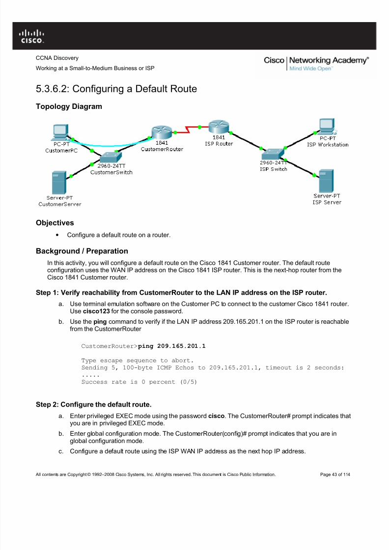
In this activity, you will configure a default route on the Cisco 1841 Customer router. The default routeconfiguration uses the WAN IP address on the Cisco 1841 ISP router. This is the next-hop router from theCisco 1841 Customer router.
Step 1: Verify reachability from CustomerRouter to the LAN IP address on the ISP router.
a. Use terminal emulation software on the Customer PC to connect to the customer Cisco 1841 router.Use cisco123 for the console password.
b. Use the ping command to verify if the LAN IP address 209.165.201.1 on the ISP router is reachablefrom the CustomerRouter
CustomerRouter> ping 209.165.201.1
Type escape sequence to abort.Sending 5, 100-byte ICMP Echos to 209.165.201.1, timeout is 2 seconds:.....Success rate is 0 percent (0/5)
Step 2: Configure the default route.
a. Enter privileged EXEC mode using the password cisco. The CustomerRouter# prompt indicates thatyou are in privileged EXEC mode.
b. Enter global configuration mode. The CustomerRouter(config)# prompt indicates that you are inglobal configuration mode.
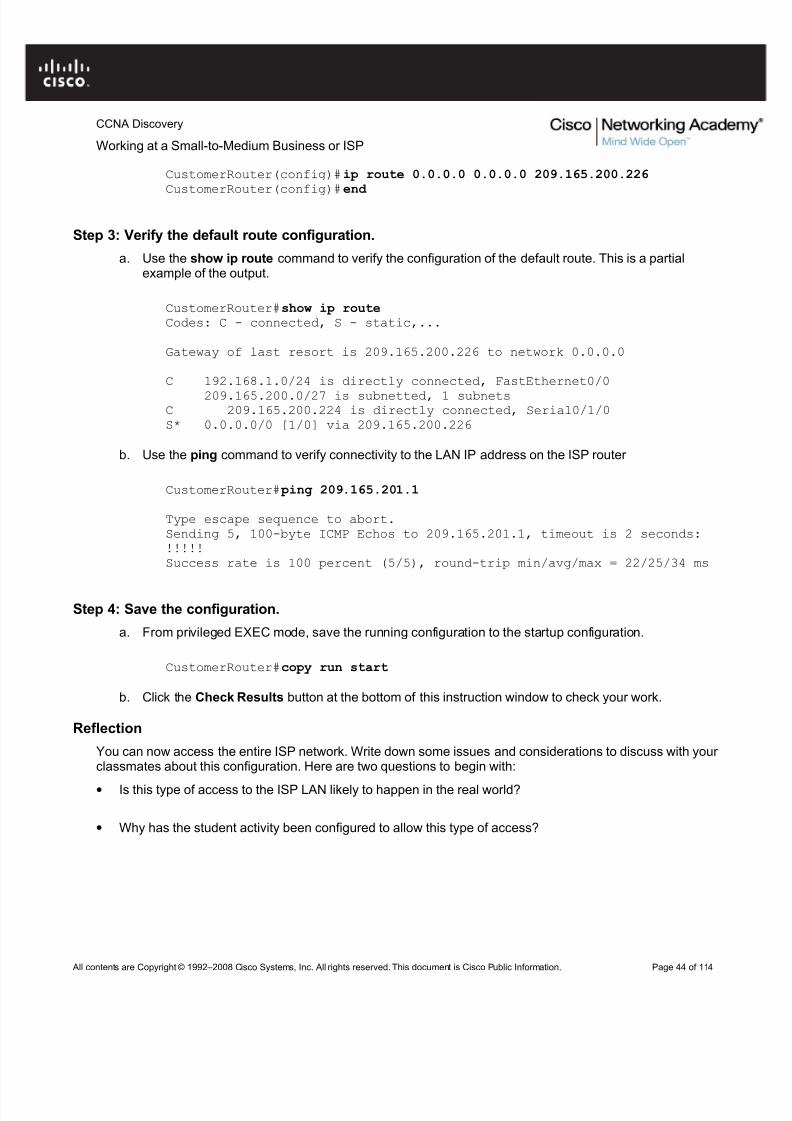
c. Configure a default route using the ISP WAN IP address as the next hop IP address.
a. Use the show ip route command to verify the configuration of the default route. This is a partialexample of the output.
CustomerRouter#show ip route Codes: C - connected, S - static,...
Gateway of last resort is 209.165.200.226 to network 0.0.0.0
C 192.168.1.0/24 is directly connected, FastEthernet0/0
209.165.200.0/27 is subnetted, 1 subnetsC 209.165.200.224 is directly connected, Serial0/1/0S* 0.0.0.0/0 [1/0] via 209.165.200.226
b. Use the ping command to verify connectivity to the LAN IP address on the ISP router
CustomerRouter# ping 209.165.201.1
Type escape sequence to abort.Sending 5, 100-byte ICMP Echos to 209.165.201.1, timeout is 2 seconds:!!!!!Success rate is 100 percent (5/5), round-trip min/avg/max = 22/25/34 ms
Step 4: Save the configuration.
a. From privileged EXEC mode, save the running configuration to the startup configuration.
CustomerRouter#copy run start
b. Click the Check Results button at the bottom of this instruction window to check your work.
Reflection
You can now access the entire ISP network. Write down some issues and considerations to discuss with your classmates about this configuration. Here are two questions to begin with:
• Is this type of access to the ISP LAN likely to happen in the real world?
• Why has the student activity been configured to allow this type of access?
5.3.7.2: Configuring a Cisco Router as a DHCP Server
Topology Diagram
Objectives
• Configure the customer Cisco 1841 ISR as a DHCP server.
Background / Preparation
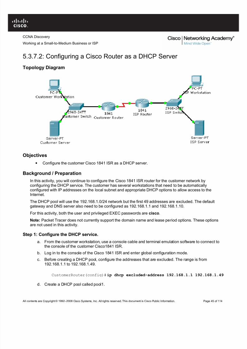
In this activity, you will continue to configure the Cisco 1841 ISR router for the customer network byconfiguring the DHCP service. The customer has several workstations that need to be automaticallyconfigured with IP addresses on the local subnet and appropriate DHCP options to allow access to theInternet.
The DHCP pool will use the 192.168.1.0/24 network but the first 49 addresses are excluded. The defaultgateway and DNS server also need to be configured as 192.168.1.1 and 192.168.1.10.
For this activity, both the user and privileged EXEC passwords are cisco.
Note: Packet Tracer does not currently support the domain name and lease period options. These optionsare not used in this activity.
Step 1: Configure the DHCP service.
a. From the customer workstation, use a console cable and terminal emulation software to connect tothe console of the customer Cisco1841 ISR.
b. Log in to the console of the Cisco 1841 ISR and enter global configuration mode.
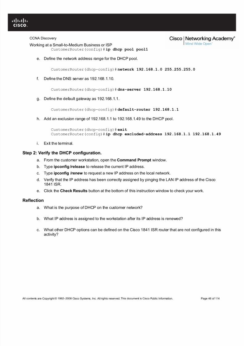
c. Before creating a DHCP pool, configure the addresses that are excluded. The range is from192.168.1.1 to 192.168.1.49.
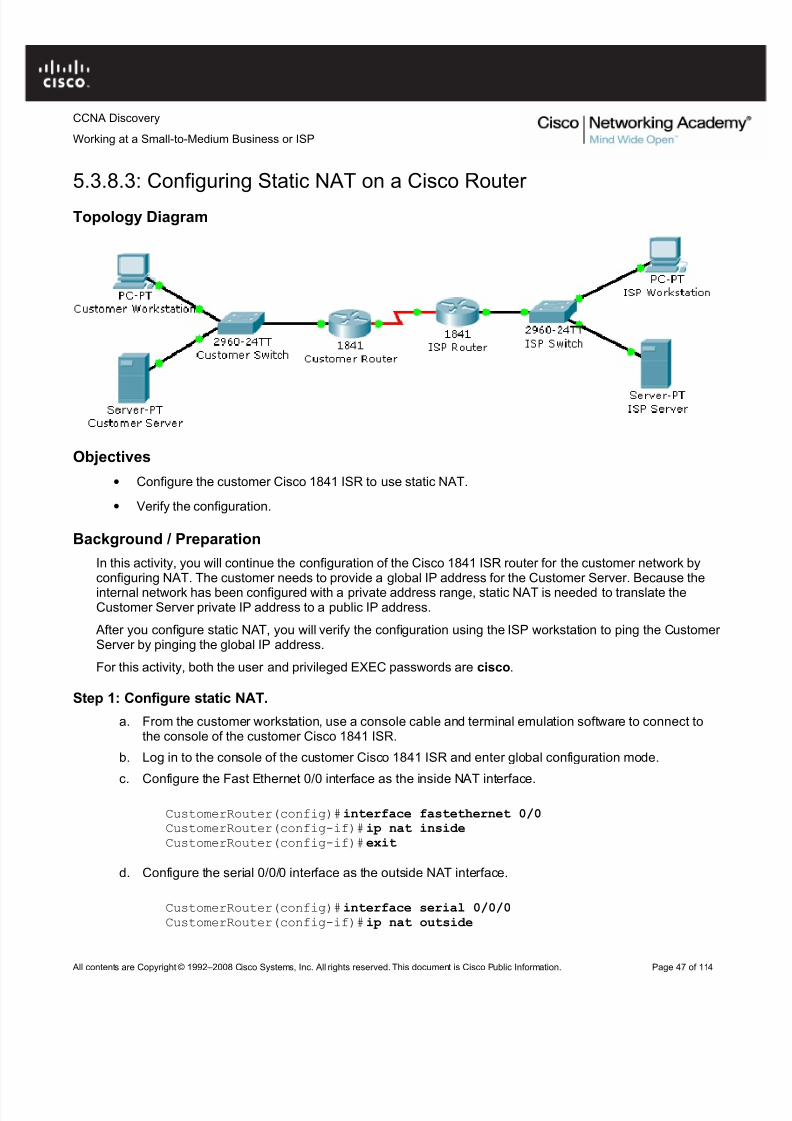
• Configure the customer Cisco 1841 ISR to use static NAT.
• Verify the configuration.
Background / Preparation
In this activity, you will continue the configuration of the Cisco 1841 ISR router for the customer network byconfiguring NAT. The customer needs to provide a global IP address for the Customer Server. Because the
internal network has been configured with a private address range, static NAT is needed to translate theCustomer Server private IP address to a public IP address.
After you configure static NAT, you will verify the configuration using the ISP workstation to ping the Customer Server by pinging the global IP address.
For this activity, both the user and privileged EXEC passwords are cisco.
Step 1: Configure static NAT.
a. From the customer workstation, use a console cable and terminal emulation software to connect tothe console of the customer Cisco 1841 ISR.
b. Log in to the console of the customer Cisco 1841 ISR and enter global configuration mode.
c. Configure the Fast Ethernet 0/0 interface as the inside NAT interface.
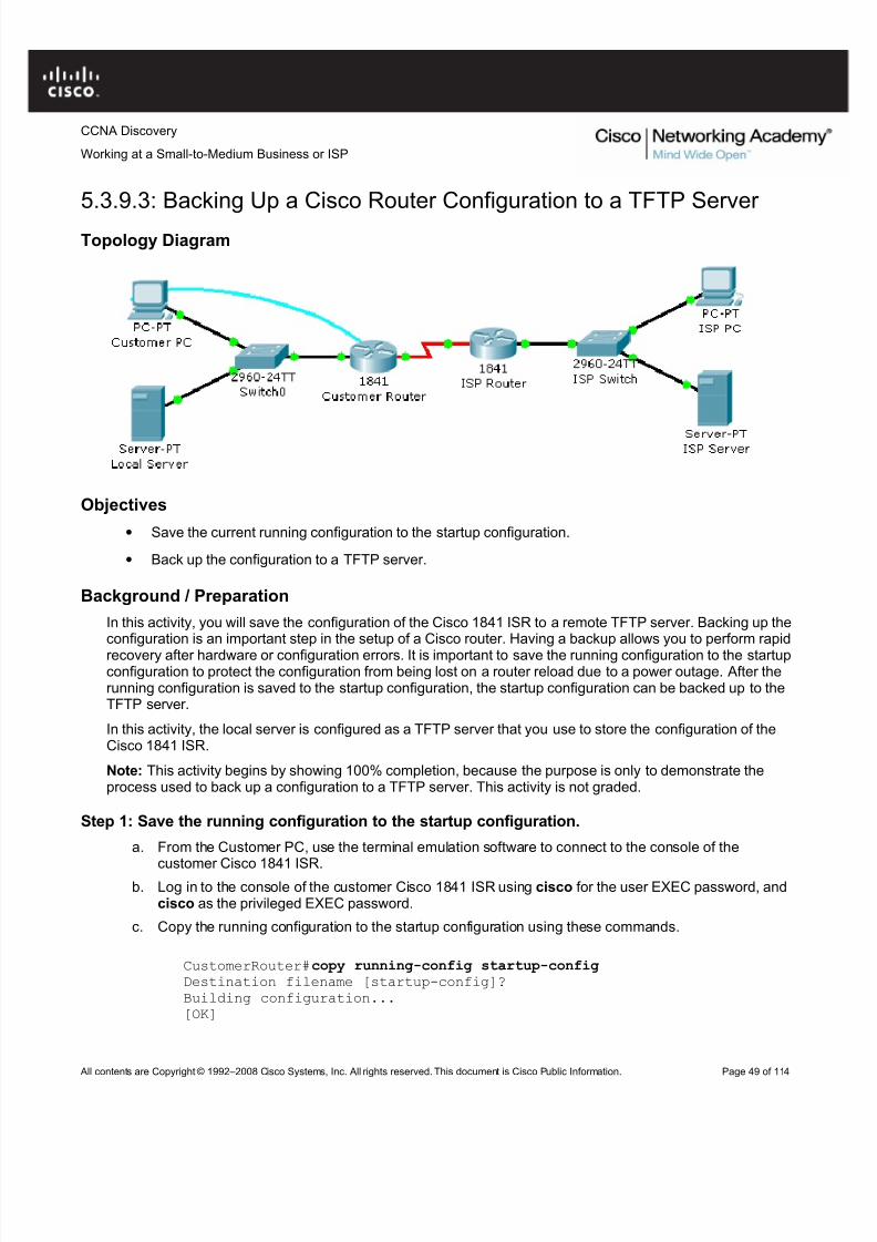
5.3.9.3: Backing Up a Cisco Router Configuration to a TFTP Server
Topology Diagram
Objectives
• Save the current running configuration to the startup configuration.
• Back up the configuration to a TFTP server.
Background / Preparation
In this activity, you will save the configuration of the Cisco 1841 ISR to a remote TFTP server. Backing up theconfiguration is an important step in the setup of a Cisco router. Having a backup allows you to perform rapid
recovery after hardware or configuration errors. It is important to save the running configuration to the startupconfiguration to protect the configuration from being lost on a router reload due to a power outage. After therunning configuration is saved to the startup configuration, the startup configuration can be backed up to theTFTP server.
In this activity, the local server is configured as a TFTP server that you use to store the configuration of theCisco 1841 ISR.
Note: This activity begins by showing 100% completion, because the purpose is only to demonstrate theprocess used to back up a configuration to a TFTP server. This activity is not graded.
Step 1: Save the running configuration to the startup configuration.
a. From the Customer PC, use the terminal emulation software to connect to the console of the
customer Cisco 1841 ISR.b. Log in to the console of the customer Cisco 1841 ISR using cisco for the user EXEC password, and
cisco as the privileged EXEC password.
c. Copy the running configuration to the startup configuration using these commands.
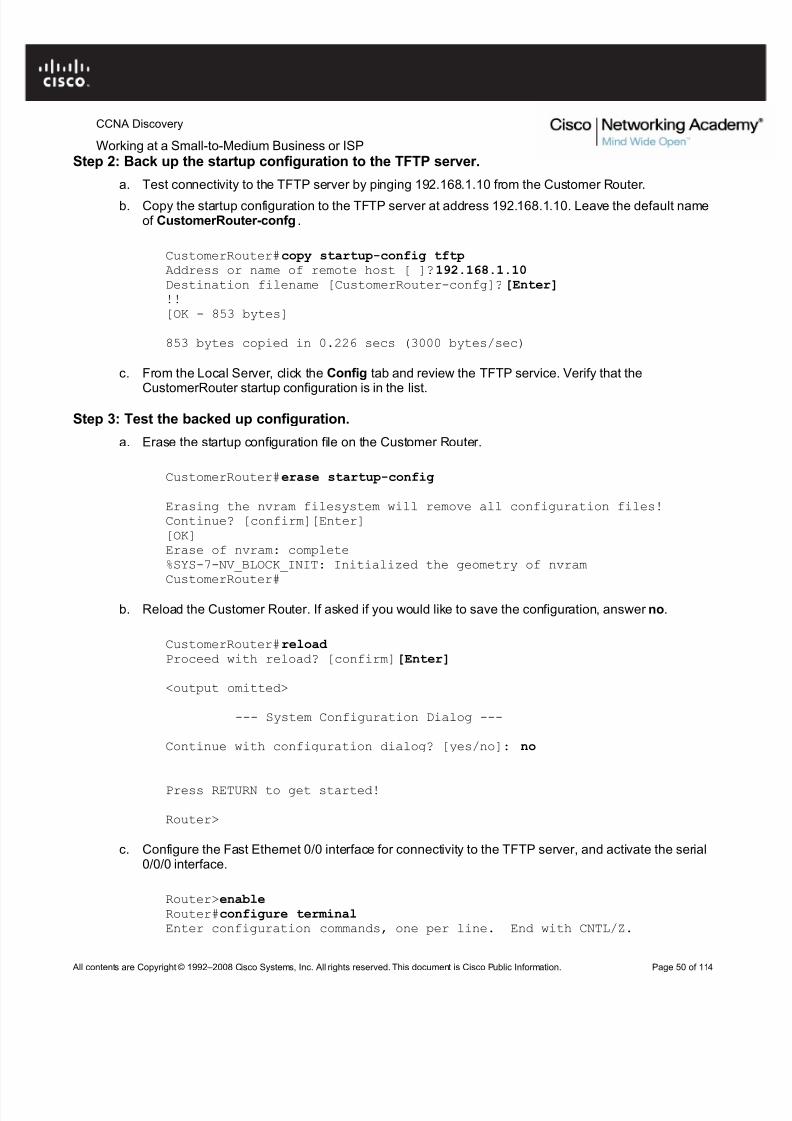
Working at a Small-to-Medium Business or ISPStep 2: Back up the startup configuration to the TFTP server.
a. Test connectivity to the TFTP server by pinging 192.168.1.10 from the Customer Router.
b. Copy the startup configuration to the TFTP server at address 192.168.1.10. Leave the default nameof CustomerRouter-confg .
CustomerRouter#copy startup-config tftpAddress or name of remote host [ ]?192.168.1.10Destination filename [CustomerRouter-confg]?[Enter] !![OK - 853 bytes]
853 bytes copied in 0.226 secs (3000 bytes/sec)
c. From the Local Server, click the Config tab and review the TFTP service. Verify that the
CustomerRouter startup configuration is in the list.
Step 3: Test the backed up configuration.
a. Erase the startup configuration file on the Customer Router.
CustomerRouter#erase startup-config
Erasing the nvram filesystem will remove all configuration files!Continue? [confirm][Enter][OK]Erase of nvram: complete%SYS-7-NV_BLOCK_INIT: Initialized the geometry of nvramCustomerRouter#
b. Reload the Customer Router. If asked if you would like to save the configuration, answer no.
CustomerRouter#reload Proceed with reload? [confirm][Enter]
<output omitted>
--- System Configuration Dialog ---
Continue with configuration dialog? [yes/no]: no
Press RETURN to get started!
Router>
c. Configure the Fast Ethernet 0/0 interface for connectivity to the TFTP server, and activate the serial0/0/0 interface.
Router>enableRouter#configure terminalEnter configuration commands, one per line. End with CNTL/Z.
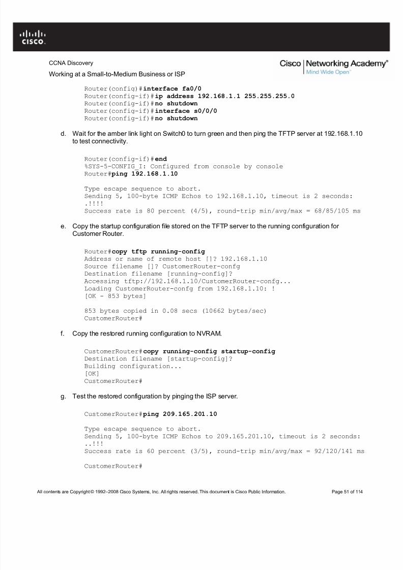
d. Wait for the amber link light on Switch0 to turn green and then ping the TFTP server at 192.168.1.10to test connectivity.
Router(config-if)#end %SYS-5-CONFIG_I: Configured from console by consoleRouter# ping 192.168.1.10
Type escape sequence to abort.Sending 5, 100-byte ICMP Echos to 192.168.1.10, timeout is 2 seconds:.!!!!Success rate is 80 percent (4/5), round-trip min/avg/max = 68/85/105 ms
e. Copy the startup configuration file stored on the TFTP server to the running configuration for Customer Router.
Router#copy tftp running-configAddress or name of remote host []? 192.168.1.10Source filename []? CustomerRouter-confgDestination filename [running-config]?Accessing tftp://192.168.1.10/CustomerRouter-confg...Loading CustomerRouter-confg from 192.168.1.10: !
[OK - 853 bytes]
853 bytes copied in 0.08 secs (10662 bytes/sec)CustomerRouter#
f. Copy the restored running configuration to NVRAM.
g. Test the restored configuration by pinging the ISP server.
CustomerRouter# ping 209.165.201.10
Type escape sequence to abort.Sending 5, 100-byte ICMP Echos to 209.165.201.10, timeout is 2 seconds:..!!!Success rate is 60 percent (3/5), round-trip min/avg/max = 92/120/141 ms
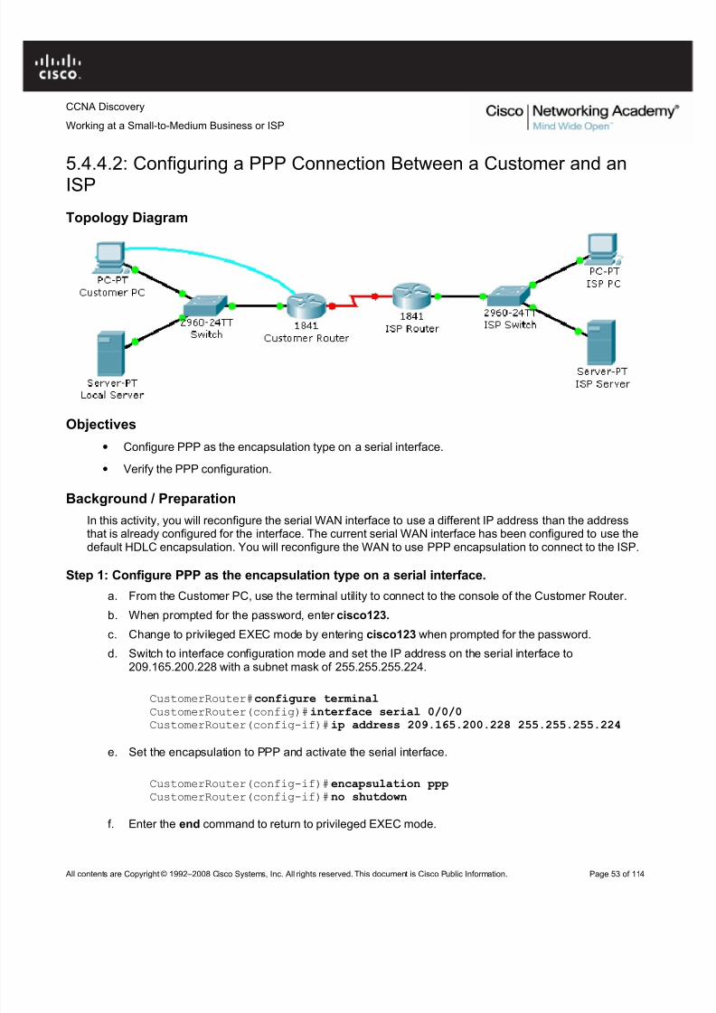
5.4.4.2: Configuring a PPP Connection Between a Customer and anISP
Topology Diagram
Objectives
• Configure PPP as the encapsulation type on a serial interface.
• Verify the PPP configuration.
Background / Preparation
In this activity, you will reconfigure the serial WAN interface to use a different IP address than the address
that is already configured for the interface. The current serial WAN interface has been configured to use thedefault HDLC encapsulation. You will reconfigure the WAN to use PPP encapsulation to connect to the ISP.
Step 1: Configure PPP as the encapsulation type on a serial interface.
a. From the Customer PC, use the terminal utility to connect to the console of the Customer Router.
b. When prompted for the password, enter cisco123.
c. Change to privileged EXEC mode by entering cisco123 when prompted for the password.
d. Switch to interface configuration mode and set the IP address on the serial interface to209.165.200.228 with a subnet mask of 255.255.255.224.
CustomerRouter#configure terminal
CustomerRouter(config)#interface serial 0/0/0CustomerRouter(config-if)#ip address 209.165.200.228 255.255.255.224
e. Set the encapsulation to PPP and activate the serial interface.
Working at a Small-to-Medium Business or ISPCustomerRouter(config-if)#end CustomerRouter#
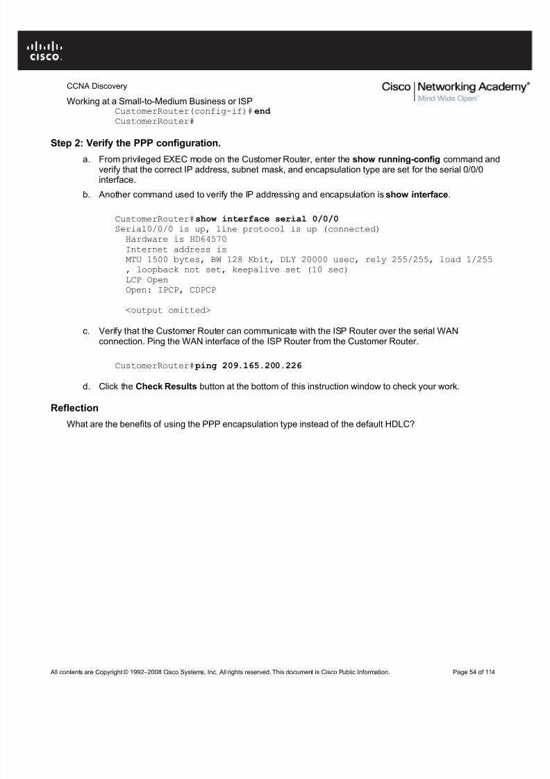
Step 2: Verify the PPP configuration.
a. From privileged EXEC mode on the Customer Router, enter the show running-config command andverify that the correct IP address, subnet mask, and encapsulation type are set for the serial 0/0/0interface.
b. Another command used to verify the IP addressing and encapsulation is show interface.
CustomerRouter#show interface serial 0/0/0Serial0/0/0 is up, line protocol is up (connected)Hardware is HD64570Internet address isMTU 1500 bytes, BW 128 Kbit, DLY 20000 usec, rely 255/255, load 1/255
, loopback not set, keepalive set (10 sec)LCP OpenOpen: IPCP, CDPCP
<output omitted>
c. Verify that the Customer Router can communicate with the ISP Router over the serial WANconnection. Ping the WAN interface of the ISP Router from the Customer Router.
CustomerRouter# ping 209.165.200.226
d. Click the Check Results button at the bottom of this instruction window to check your work.
ReflectionWhat are the benefits of using the PPP encapsulation type instead of the default HDLC?
Step 5: Configure an IP address on interface VLAN1.
From global configuration mode, switch to interface configuration mode for VLAN1, and assign the IP address192.168.1.5 with the subnet mask of 255.255.255.0.
Working at a Small-to-Medium Business or ISPb. Click the Check Results button at the bottom of this instruction window to check your work.
Step 7: Verify the configuration.The Customer Switch should now be able to ping the ISP Server at 209.165.201.10. The first one or twopings may fail while ARP converges.
Type escape sequence to abort.Sending 5, 100-byte ICMP Echos to 209.165.201.10, timeout is 2 seconds:..!!!Success rate is 60 percent (3/5), round-trip min/avg/max = 181/189/197ms
CustomerSwitch#
Reflection
a. What is the significance of assigning the IP address to the VLAN1 interface instead of any of the FastEthernet interfaces?
b. What command is necessary to enforce password authentication on the console and vty lines?
c. How many gigabit ports are available on the Cisco Catalyst 2960 switch that you used in the activity?
In this activity, you will verify the configuration on the customer Cisco Catalyst 2960 switch. The switch isalready configured with all the basic necessary information for connecting to the LAN at the customer site.The switch is currently not connected to the network. You will connect the switch to the customer workstation,the customer server, and customer router. You will verify that the switch has been connected and configuredsuccessfully by pinging the LAN interface of the customer router.
Step 1: Connect the switch to the LAN.
a. Using the proper cable, connect the FastEthernet0/0 on Customer Router to the FastEthernet0/1 onCustomer Switch.
b. Using the proper cable, connect the Customer PC to the Customer Switch on port FastEthernet0/2.
c. Using the proper cable, connect the Local Server to the Customer Switch on port FastEthernet0/3.
Step 2: Verify the switch configuration.a. From the Customer PC, use the terminal emulation software to connect to the console of the
customer Cisco Catalyst 2960 switch.
b. Use the console connection and terminal utility on the Customer PC to verify the configurations. Usecisco as the console password.
c. Enter privileged EXEC mode and use the show running-config command to verify the followingconfigurations. The password is cisco123.
Working at a Small-to-Medium Business or ISP• Subnet mask = 255.255.255.0
• Password required for console access
• Password required for vty access
• Password enabled for privileged EXEC mode
• Secret enabled for privileged EXEC mode
d. Verify IP connectivity between the Cisco Catalyst 2960 switch and the Cisco 1841 router by initiatinga ping to 192.168.1.1 from the switch CLI.
e. Click the Check Results button at the bottom of this instruction window to check your work.
Reflection
a. What is the significance of the enable secret command compared to the enable password?
f. If you want to remove the requirement to enter a password to access the console, what commandsdo you issue from your starting point in privileged EXEC mode?
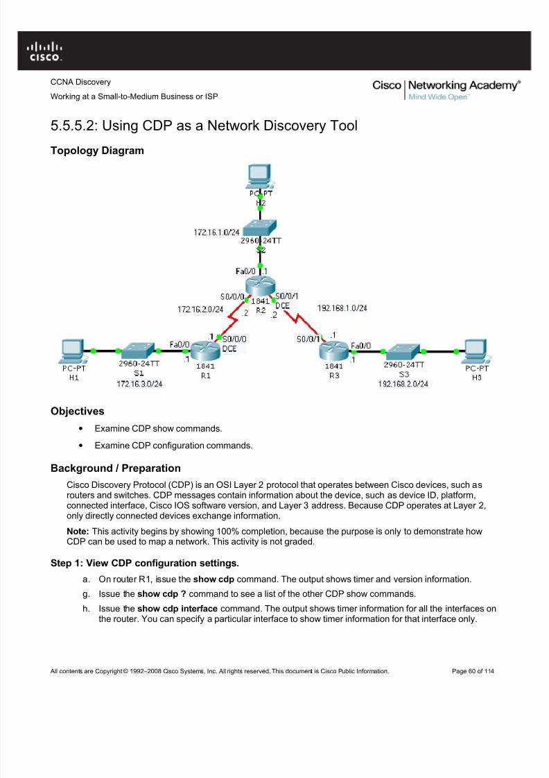
Cisco Discovery Protocol (CDP) is an OSI Layer 2 protocol that operates between Cisco devices, such asrouters and switches. CDP messages contain information about the device, such as device ID, platform,connected interface, Cisco IOS software version, and Layer 3 address. Because CDP operates at Layer 2,only directly connected devices exchange information.
Note: This activity begins by showing 100% completion, because the purpose is only to demonstrate how
CDP can be used to map a network. This activity is not graded.
Step 1: View CDP configuration settings.
a. On router R1, issue the show cdp command. The output shows timer and version information.
g. Issue the show cdp ? command to see a list of the other CDP show commands.
h. Issue the show cdp interface command. The output shows timer information for all the interfaces onthe router. You can specify a particular interface to show timer information for that interface only.
Working at a Small-to-Medium Business or ISPStep 2: View CDP neighbor information.
a. A router builds a table of information about neighboring devices from CDP messages received from
those devices. On router R1, issue the show cdp neighbors command.
Packet Tracer operates in real time, like actual network equipment. If you do not see two entries inthe output of the command, wait a couple of minutes and reissue the command until you do.
i. Examine the output. A single line of information is displayed for each device. Information is displayedfor switch S1 and router R2, which are directly connected, but not for router R3, which is not directlyconnected.
j. Issue the show cdp entry R2 command. Examine the output. More detailed information about router R2 is displayed, including the IP address used to reach the router.
k. Issue the show cdp entry * command. Examine the output. Detailed information about all directlyconnected devices is displayed.
l. Issue the show cdp neighbors detail command. Examine the output. The same information as the
show cdp entry * command is displayed.
Step 3: Disable and enable CDP globally on a router.
a. On router R2, issue the show cdp neighbors command. The output shows information about thethree directly connected devices.
m. Enter global configuration mode. Issue the no cdp run command to disable CDP on the router. Exitconfiguration mode and issue the show cdp neighbors command. The output shows that CDP is notenabled.
n. On router R1, issue the show cdp neighbors command. If the output shows an entry for R2, wait thenumber of seconds shown for the Holdtime entry on R2, and then reissue the command.
The entry for R2 will no longer be shown because no CDP messages were received before the
Holdtime expired.o. On router R2, enter global configuration mode. Issue the cdp run command to enable CDP on the
router.
Step 4: Disable and enable CDP on an interface.
a. You may not want to send CDP information to Cisco devices on an untrusted network. It is possible todisable CDP on a specific interface.
b. On router R2, enter global configuration mode. Enter interface configuration mode for interfaceSerial0/0/1, and issue the no cdp enable command to disable CDP on the interface. Exitconfiguration mode.
c. Issue the show cdp neighbors command on both router R2 and router R3 until the entry for R3times out of the CDP table on R2, and the entry for R2 times out of the CDP table on R3.
d. On router R2, enter global configuration mode. Enter interface configuration mode for interfaceSerial0/0/1, and issue the cdp enable command to enable CDP on the interface.
Reflection
You now have a basic understanding of CDP. Write down some issues and considerations to discuss withyour classmates about CDP. For a start, here are two questions:
• How could CDP be used to troubleshoot network connectivity issues?
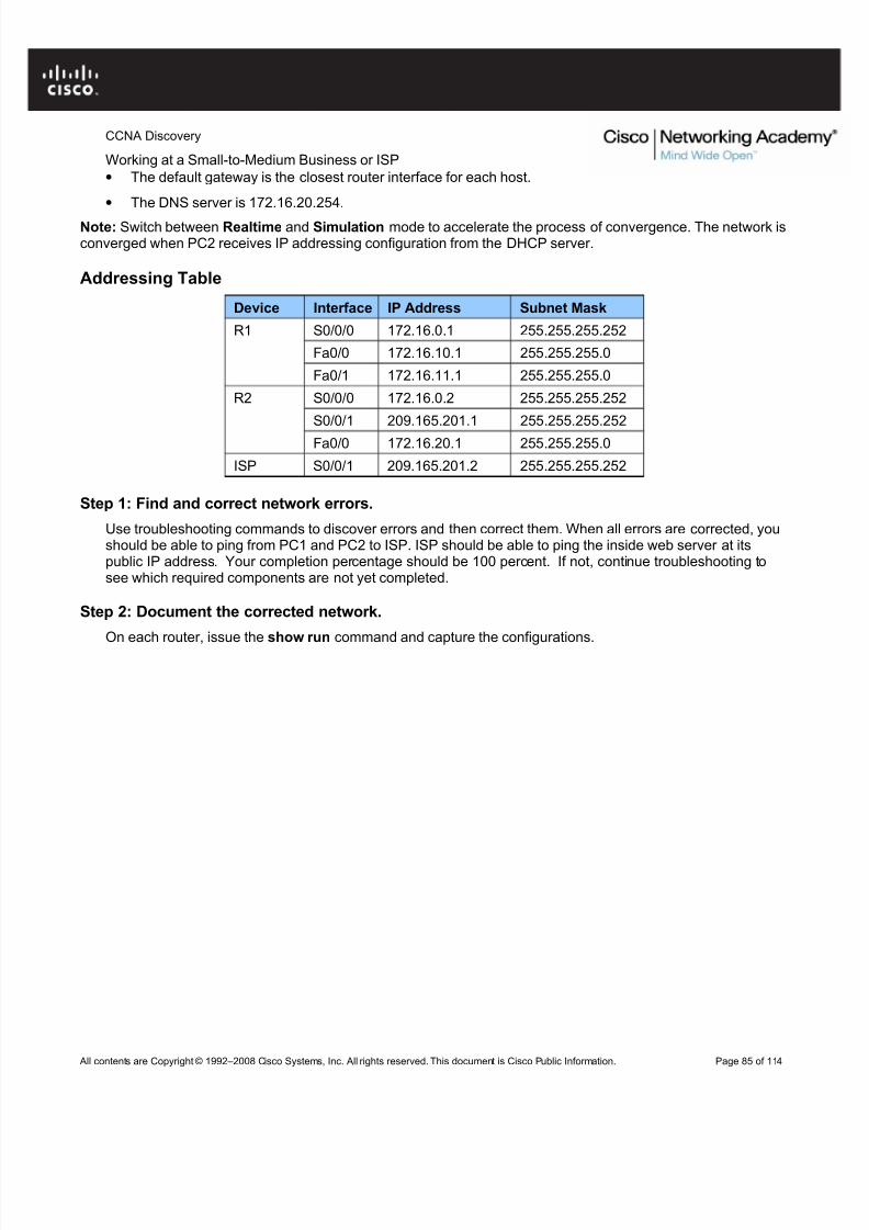
• Configure static routes on each router to allow communication between all clients.
• Test connectivity to ensure that each device can fully communicate with all other devices.
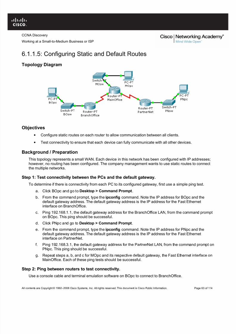
Background / Preparation
This topology represents a small WAN. Each device in this network has been configured with IP addresses;however, no routing has been configured. The company management wants to use static routes to connectthe multiple networks.
Step 1: Test connectivity between the PCs and the default gateway.
To determine if there is connectivity from each PC to its configured gateway, first use a simple ping test.
a. Click BOpc and go to Desktop > Command Prompt.
b. From the command prompt, type the ipconfig command. Note the IP address for BOpc and thedefault gateway address. The default gateway address is the IP address for the Fast Ethernetinterface on BranchOffice.
c. Ping 192.168.1.1, the default gateway address for the BranchOffice LAN, from the command prompton BOpc. This ping should be successful.
d. Click PNpc and go to Desktop > Command Prompt.
e. From the command prompt, type the ipconfig command. Note the IP address for PNpc and the
default gateway address. The default gateway address is the IP address for the Fast Ethernetinterface on PartnerNet.
f. Ping 192.168.3.1, the default gateway address for the PartnerNet LAN, from the command prompt onPNpc. This ping should be successful.
g. Repeat steps a, b, and c for MOpc and its respective default gateway, the Fast Ethernet interface onMainOffice. Each of these ping tests should be successful.
Step 2: Ping between routers to test connectivity.
Use a console cable and terminal emulation software on BOpc to connect to BranchOffice.
Working at a Small-to-Medium Business or ISPa. Test connectivity with MainOffice by pinging 10.10.10.1, the IP address of the directly connected
serial 3/0 interface. This ping should succeed.
p. Test connectivity with MainOffice by pinging 10.10.10.5, the IP address of the serial 2/0 interface.This ping should fail.
q. Issue the show ip route command from the terminal window of BOpc. Note that only directlyconnected routes are shown in the BranchOffice routing table. The ping to 10.10.10.5 failed becausethe BranchOffice router has no routing table entry for 10.10.10.5.
r. Repeat steps a through d on the other two PCs. The pings to directly connected networks willsucceed. However, pings to remote networks will fail.
s. What steps must be taken to reach all the networks from any PC in the activity?
Step 3: Viewing the routing tables.
You can view routing tables in Packet Tracer using the Inspect tool. The Inspect tool is in the Common Toolsbar to the right of the topology. The Inspect tool is the icon that appears as a magnifying glass.
a. In the Common Tools bar, click on the Inspect tool.
t. Click the MainOffice router and choose Routing Table.
u. Click the BranchOffice router and choose Routing Table.
v. Click the PartnerNet router and choose Routing Table.
w. Move the routing table windows around so that you can see all three at once.
x. What networks do each of the routers already know about?
y. Does each router know how to route to all networks in the topology? After comparing the routing
tables, close the window for each routing table by clicking the x in the upper right corner of eachwindow.
Step 4: Configure default routes on the BranchOffice and PartnerNet routers.
To configure static routes for each router, first determine which routes need to be added for each device. For the BranchOffice and the PartnerNet routers, a single default route allows these devices to route traffic for allnetworks not directly connected. To configure a default route, you must identify the IP address of the next hoprouter, which in this case is the MainOffice router.
a. From the Common toolbar, click the Select tool.
b. Move the cursor over the red serial link between the BranchOffice router and the MainOffice router.Notice that the interface of the next hop is S3/0.
c. Move the cursor over the MainOffice router and note that the IP address for Serial 3/0 is 10.10.10.1.
d. Move the cursor over the red serial link between the PartnerNet router and the MainOffice router.Notice that the interface of the next hop is S2/0.
e. Move the cursor over the MainOffice router and note that the IP address for Serial 2/0 is 10.10.10.5.
f. Configure the static routes on both the BranchOffice and PartnerNet routers using the CLI. Click theBranchOffice router, and click the CLI tab.
g. At the BranchOffice> prompt, type enable to enter privileged EXEC mode.
h. At the BranchOffice# prompt, type configure terminal.
Working at a Small-to-Medium Business or ISPi. The syntax for a default route is ip route 0.0.0.0 0.0.0.0 next_hop_ip_address. Type ip route
0.0.0.0 0.0.0.0 10.10.10.1.
j. Type end to get back to the BranchOffice# prompt.k. Type copy run start to save the configuration change.
l. Repeat steps f through k on the PartnerNet router, using 10.10.10.5 as the next hop IP address.
Step 5: Configure static routes at Main Office.
The configuration of static routes at the Main Office is a bit more complex because the MainOffice router isresponsible for routing traffic to and from the Branch Office and PartnerNet LAN segments.
The MainOffice router knows only about routes to the 10.10.10.0/30, 10.10.10.4/30, and 192.168.2.0/24networks because they are directly connected. Static routes to the 192.168.1.0/24 and 192.168.3.0/24networks need to be added so that the MainOffice router can route traffic between the networks behind theBranchOffice and PartnerNet routers.
a. Click the MainOffice router, and then click the CLI tab.
z. At the MainOffice> prompt, type enable to enter privileged EXEC mode.
aa. At the MainOffice# prompt, type configure terminal.
bb. The syntax for a static route is ip route network subnet_mask next_hop_ip_address:
ip route 192.168.1.0 255.255.255.0 10.10.10.2ip route 192.168.3.0 255.255.255.0 10.10.10.6
cc. Type end to return to the MainOffice# prompt.
dd. Type copy run start to save the configuration change.
ee. Repeat steps a through e from Step 3. View the routing tables and notice the difference in the routingtables. The routing table for each router should have an “S” for each static route.
Step 6: Test connectivity.
Now that each router in the topology has static routes configured, all hosts should have connectivity to allother hosts. Use ping to verify connectivity.
a. Click BOpc and click the Desktop tab.
b. Choose the Command prompt option.
c. Type ping 192.168.3.2. The ping should be successful, verifying that the static routes are configuredproperly.
d. Type ping 192.168.2.2. Notice that the result is successful even though you did not specifically add
the 192.168.2.0 network as a static route into any of the routers. Because a default route was usedon the BranchOffice and PartnerNet routers, a route for the 192.168.2.0 network was not needed.The default route sends all traffic destined off network to the MainOffice router. The 192.168.2.0network is directly connected to the MainOffice router; therefore, no additional routes needed to beadded to the routing table
e. Click the Check Results button at the bottom of this instruction window to check your work.
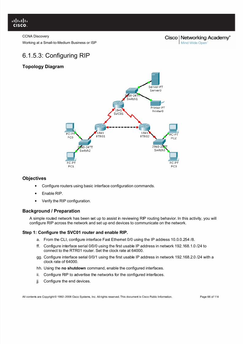
Objectives• Configure routers using basic interface configuration commands.
• Enable RIP.
• Verify the RIP configuration.
Background / Preparation
A simple routed network has been set up to assist in reviewing RIP routing behavior. In this activity, you willconfigure RIP across the network and set up end devices to communicate on the network.
Step 1: Configure the SVC01 router and enable RIP.
a. From the CLI, configure interface Fast Ethernet 0/0 using the IP address 10.0.0.254 /8.ff. Configure interface serial 0/0/0 using the first usable IP address in network 192.168.1.0 /24 to
connect to the RTR01 router. Set the clock rate at 64000.
gg. Configure interface serial 0/0/1 using the first usable IP address in network 192.168.2.0 /24 with aclock rate of 64000.
hh. Using the no shutdown command, enable the configured interfaces.
ii. Configure RIP to advertise the networks for the configured interfaces.
Working at a Small-to-Medium Business or ISP• Server0 uses the first usable IP address in network 10.0.0.0 /8. Specify the appropriate default
gateway and subnet mask.
• Printer0 uses the second usable IP address in network 10.0.0.0 /8. Specify the appropriatedefault gateway and subnet mask.
Step 2: Configure the RTR01 router and enable RIP.
a. Configure interface Fast Ethernet 0/0 using the first usable IP address in network 192.168.0.0 /24 toconnect to the RTR02 router.
kk. Configure interface serial 0/0/0 using the second usable IP address in network 192.168.1.0 /24 toconnect to the SVC01 router.
ll. Configure interface Fast Ethernet 0/1 using the IP address 172.16.254.254 /16.
mm. Using the no shutdown command, enable the configured interfaces.
nn. Configure RIP to advertise the networks for the configured interfaces.
oo. Configure the end devices.
• PC0 uses the first usable IP addresses in network 172.16.0.0 /16.
• PC1 uses the second usable IP address in network 172.16.0.0 /16.
• Specify the appropriate default gateway and subnet mask on each PC.
Step 3: Configure the RTR02 router and enable RIP.
a. Configure interface Fast Ethernet 0/0 using the second usable IP address in network 192.168.0.0 /24to connect to the RTR01 router.
pp. Configure interface serial 0/0/0 using the second usable IP address in network 192.168.2.0 /24 toconnect to the SVC01 router.
qq. Configure interface Fast Ethernet 0/1 using the IP address 172.17.254.254 /16.
rr. Using the no shutdown command, enable the configured interfaces.
ss. Configure RIP to advertise the networks for the configured interfaces.
tt. Configure the end devices.
• PC2 uses the first usable IP addresses in network 172.17.0.0 /16.
• PC3 uses the second usable IP address in network 172.17.0.0 /16.
• Specify the appropriate default gateway and subnet mask on each PC.
Step 4: Verify the RIP configuration on each router.
a. At the command prompt for each router, issue the commands show ip protocols and show ip routeto verify RIP routing is fully converged. The show ip protocols command displays the networks therouter is advertising and the addresses of other RIP routing neighbors. The show ip route commandoutput displays all routes know to the local router including the RIP routes which are indicated by an“R”.
b. Every device should now be able to successfully ping any other device in this activity.
c. Click the Check Results button at the bottom of this instruction window to check your work.
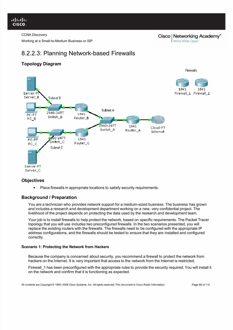
• Place firewalls in appropriate locations to satisfy security requirements.
Background / Preparation
You are a technician who provides network support for a medium-sized business. The business has grownand includes a research and development department working on a new, very confidential project. Thelivelihood of the project depends on protecting the data used by the research and development team.
Your job is to install firewalls to help protect the network, based on specific requirements. The Packet Tracer topology that you will use includes two preconfigured firewalls. In the two scenarios presented, you willreplace the existing routers with the firewalls. The firewalls need to be configured with the appropriate IPaddress configurations, and the firewalls should be tested to ensure that they are installed and configuredcorrectly.
Scenario 1: Protecting the Network from Hackers
Because the company is concerned about security, you recommend a firewall to protect the network fromhackers on the Internet. It is very important that access to the network from the Internet is restricted.
Firewall_1 has been preconfigured with the appropriate rules to provide the security required. You will install iton the network and confirm that it is functioning as expected.
Working at a Small-to-Medium Business or ISPStep 1: Replace Router_A with Firewall_1.
a. Remove Router_A and replace it with Firewall_1.
uu. Connect the Fast Ethernet 0/0 interface on Firewall_1 to the Fast Ethernet 0/1 interface on Switch_A.Connect the Fast Ethernet 0/1 interface on Firewall_1 to the Ethernet 6 interface of the ISP cloud.(Use straight-through cables for both connections.)
vv. Confirm that the host name of Firewall_1 is Firewall_1.
ww.On Firewall_1, configure the WAN IP address and subnet mask for the FastEthernet 0/1 interface as209.165.200.225 and 255.255.255.224.
xx. Configure the LAN IP address and subnet mask for the Fast Ethernet 0/0 interface on Firewall_1 as192.168.1.1 and 255.255.255.0.
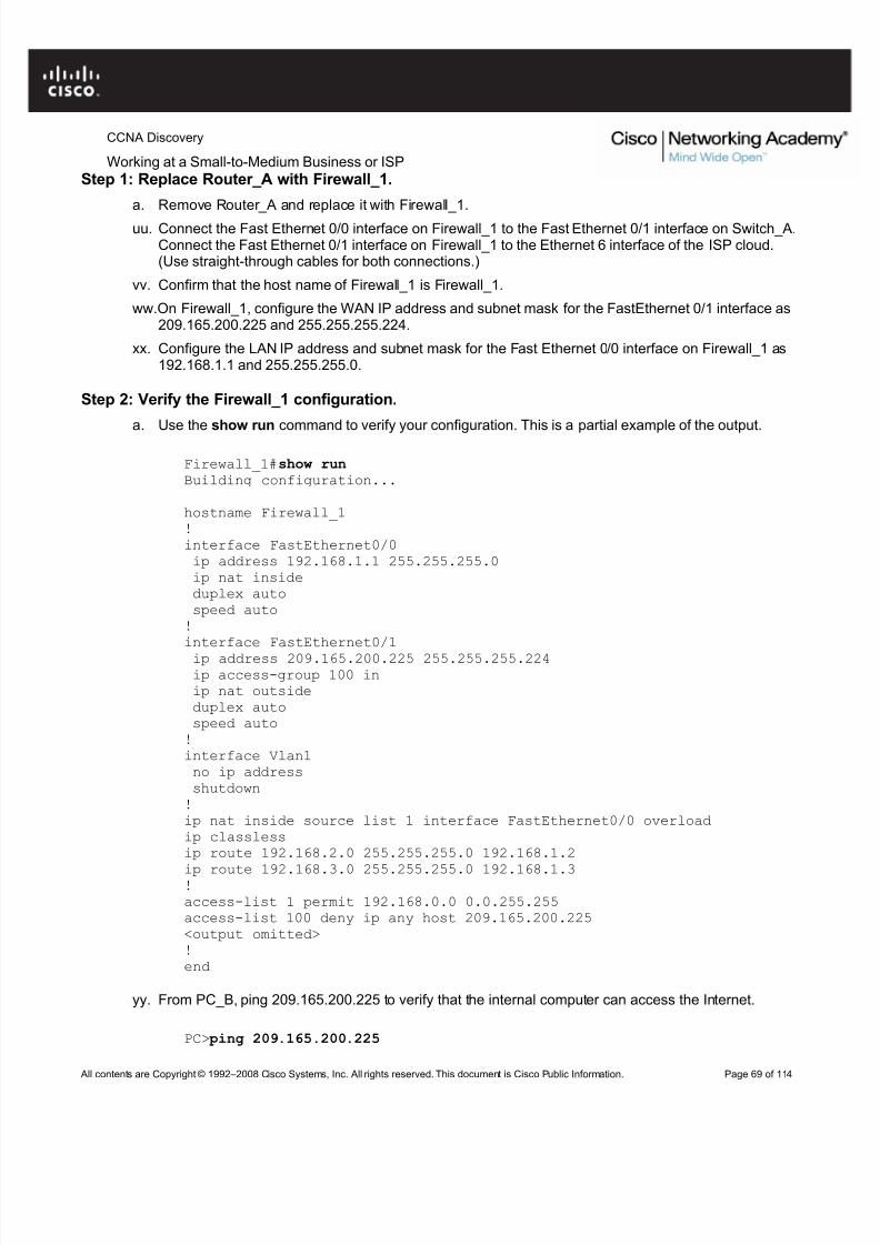
Step 2: Verify the Firewall_1 configuration.
a. Use the show run command to verify your configuration. This is a partial example of the output.
Reply from 209.165.200.225: bytes=32 time=107ms TTL=120Reply from 209.165.200.225: bytes=32 time=98ms TTL=120Reply from 209.165.200.225: bytes=32 time=104ms TTL=120Reply from 209.165.200.225: bytes=32 time=95ms TTL=120
Ping statistics for 209.165.200.225:Packets: Sent = 4, Received = 4, Lost = 0 (0% loss),
Approximate round trip times in milli-seconds:Minimum = 95ms, Maximum = 107ms, Average = 101ms
zz. From privileged EXEC mode on Firewall_1, save the running configuration to the startup configurationusing the copy run start command.
Scenario 2: Securing the Research and Development Network
Now that the entire network is secured from traffic originating from the Internet, secure the research anddevelopment network, Subnet C, from potential breaches from inside the network. The research anddevelopment team needs access to both the server on Subnet B and the Internet to conduct research.Computers on Subnet B should be denied access to the research and development subnet.
Firewall_2 has been preconfigured with the appropriate rules to provide the security required. You will install iton the network and confirm that it is functioning as expected.
Step 1: Replace Router_C with Firewall_2.
a. Remove Router_C and replace it with Firewall_2.
aaa. Connect the Fast Ethernet 0/1 interface on Firewall_2 to the Fast Ethernet 0/3 interface onSwitch_A. Connect the Fast Ethernet 0/0 interface on Firewall_2 to the Fast Ethernet 0/1 interface onSwitch_C. (Use straight-through cables for both connections.)
bbb. Confirm that the host name of Firewall_2 is Firewall_2.
ccc.On Firewall_2, configure the WAN IP address and subnet mask for the Fast Ethernet 0/1 interface as192.168.1.3 and 255.255.255.0.
ddd. Configure the LAN IP address and subnet mask for the Fast Ethernet 0/0 interface of Firewall_2as 192.168.3.1 and 255.255.255.0.
Step 2: Verify the Firewall_2 configuration.
a. Use the show run command to verify the configuration. This is a partial example of the output.
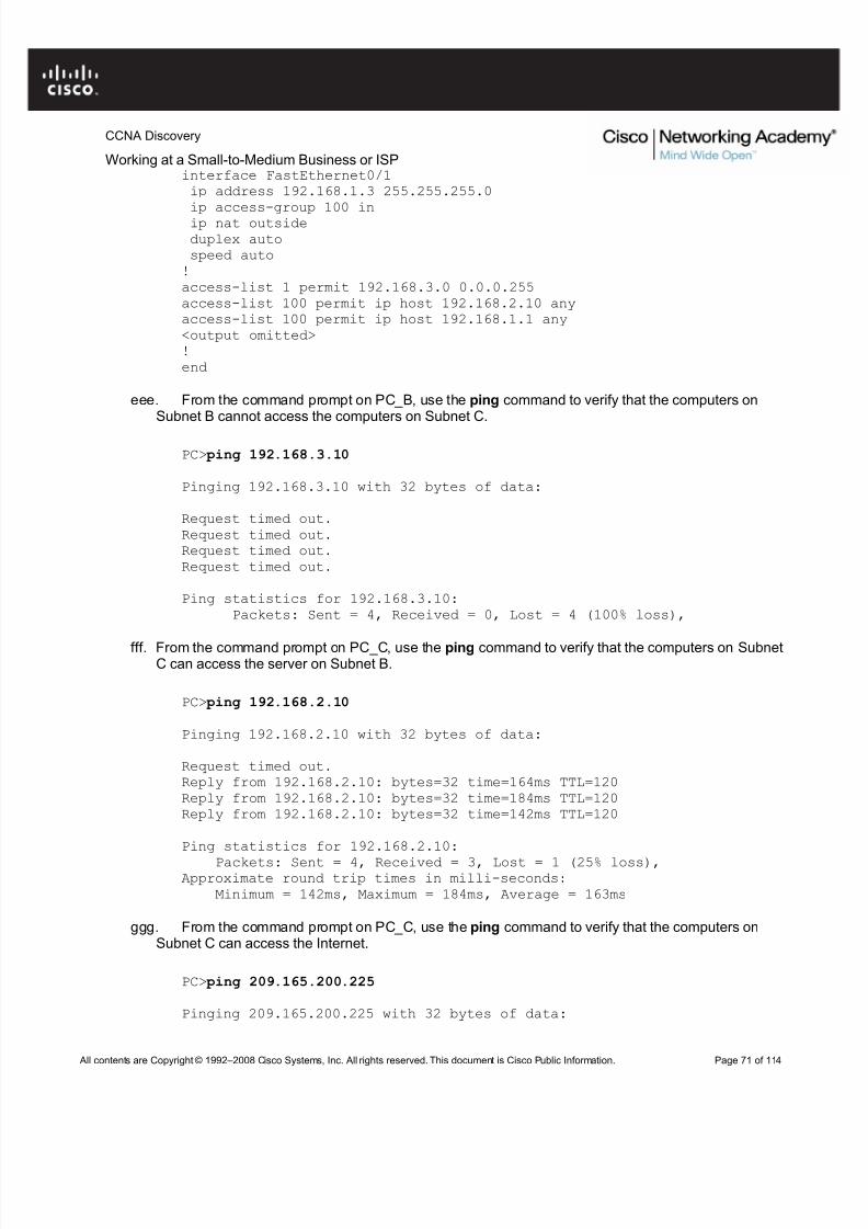
Working at a Small-to-Medium Business or ISPinterface FastEthernet0/1ip address 192.168.1.3 255.255.255.0ip access-group 100 inip nat outsideduplex autospeed auto!access-list 1 permit 192.168.3.0 0.0.0.255access-list 100 permit ip host 192.168.2.10 anyaccess-list 100 permit ip host 192.168.1.1 any<output omitted>!end
eee. From the command prompt on PC_B, use the ping command to verify that the computers onSubnet B cannot access the computers on Subnet C.
Reply from 209.165.200.225: bytes=32 time=97ms TTL=120Reply from 209.165.200.225: bytes=32 time=118ms TTL=120Reply from 209.165.200.225: bytes=32 time=100ms TTL=120Reply from 209.165.200.225: bytes=32 time=110ms TTL=120
Ping statistics for 209.165.200.225:Packets: Sent = 4, Received = 4, Lost = 0 (0% loss),
Approximate round trip times in milli-seconds:Minimum = 97ms, Maximum = 118ms, Average = 106ms
hhh. From privileged EXEC mode on Firewall_2, save the running configuration to the startupconfiguration using the copy run start command.
iii. Click the Check Results button at the bottom of this instruction window to check your work.
Reflectiona. Why would you install a firewall on the internal network?
jjj. How does a router that is configured to use NAT help protect computer systems on the inside of theNAT router?
kkk.Examine the location of Firewall_1 and Firewall_2 in the completed network topology. Whichnetworks are considered trusted and untrusted for Firewall_1? Which networks are consideredtrusted and untrusted for Firewall_2?
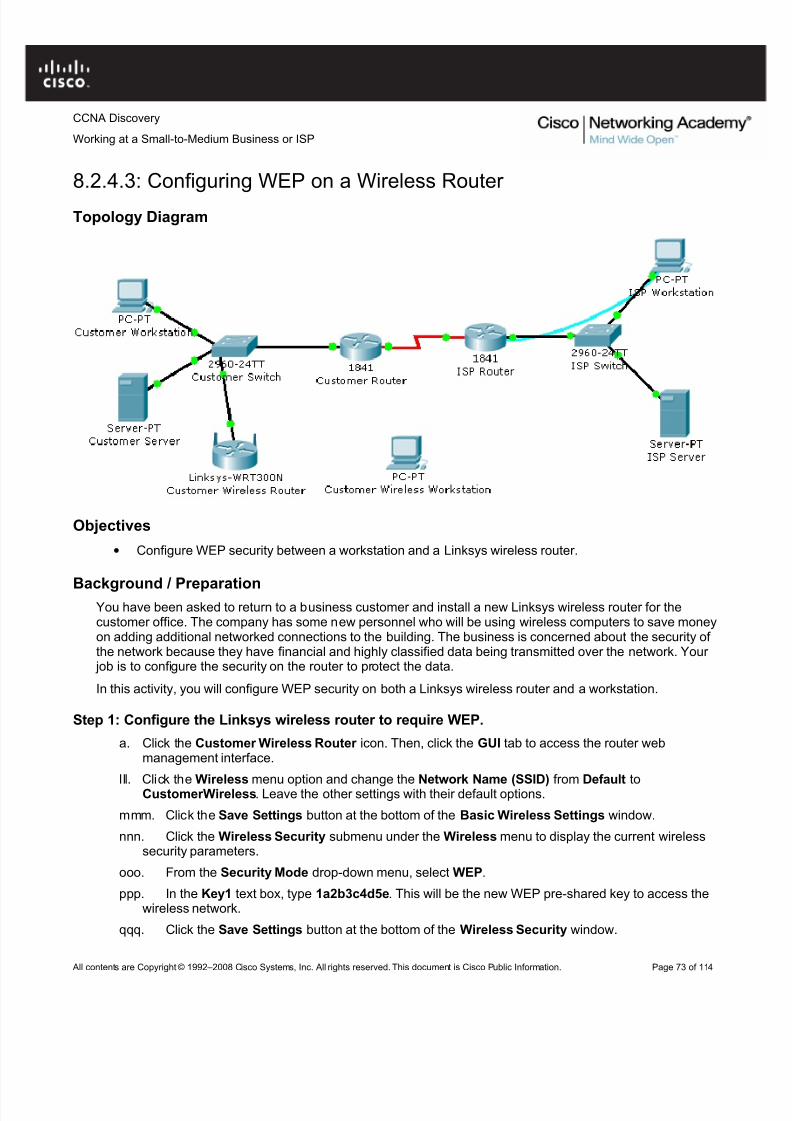
• Configure WEP security between a workstation and a Linksys wireless router.
Background / PreparationYou have been asked to return to a business customer and install a new Linksys wireless router for thecustomer office. The company has some new personnel who will be using wireless computers to save moneyon adding additional networked connections to the building. The business is concerned about the security of the network because they have financial and highly classified data being transmitted over the network. Your
job is to configure the security on the router to protect the data.
In this activity, you will configure WEP security on both a Linksys wireless router and a workstation.
Step 1: Configure the Linksys wireless router to require WEP.
a. Click the Customer Wireless Router icon. Then, click the GUI tab to access the router webmanagement interface.
lll. Click the Wireless menu option and change the Network Name (SSID) from Default toCustomerWireless. Leave the other settings with their default options.
mmm. Click the Save Settings button at the bottom of the Basic Wireless Settings window.
nnn. Click the Wireless Security submenu under the Wireless menu to display the current wirelesssecurity parameters.
ooo. From the Security Mode drop-down menu, select WEP.
ppp. In the Key1 text box, type 1a2b3c4d5e. This will be the new WEP pre-shared key to access thewireless network.
qqq. Click the Save Settings button at the bottom of the Wireless Security window.
Working at a Small-to-Medium Business or ISPStep 2: Configure WEP on the customer wireless workstation.
a. Click the Customer Wireless Workstation.
rrr. Click the Config tab.
sss.Click the Wireless button to display the current wireless configuration settings on the workstation.
ttt. Change the SSID to CustomerWireless.
uuu. Change the Security Mode to WEP. Enter 1a2b3c4d5e in the Key text box, and then close thewindow.
Step 3: Verify the configuration.
After you configure the correct WEP key and SSID on the customer wireless workstation, notice that there is awireless connection between the workstation and the wireless router.
a. Click the Customer Wireless Workstation.
b. Click the Desktop tab to view the applications that are available.
c. Click on the Command Prompt application to bring up the command prompt.
d. Type ipconfig /all and press Enter to view the current network configuration settings.
e. Type ping 192.168.2.1 to verify connectivity to the LAN interface of the customer wireless router.
f. Close the command prompt window.
g. Open a web browser.
h. In the address bar of the web browser window, type http://192.168.1.10. Press Enter . The Intranetweb page that is running on the customer server appears. You have just verified that the customer wireless workstation has connectivity to the rest of the customer network.
i. Click the Check Results button at the bottom of this instruction window to check your work.
Reflection
a. What is the purpose of using WEP on a wireless network?
b. What is the significance of the key that you used to secure WEP?
9.2.4.3: Configuring and Troubleshooting a Switched Network
Topology Diagram
Objectives
• Establish console connection to the switch.
• Configure the host name and VLAN1.
• Use the help feature to configure the clock.
• Configure passwords and console/Telnet access.
• Configure login banners.
• Configure the router.
• Solve duplex and speed mismatch problems.
• Configure port security.
• Secure unused ports.
• Manage the switch configuration file.
Background / Preparation
In this Packet Tracer Skills Integration Challenge activity, you will configure basic switch management,including general maintenance commands, passwords, and port security. This activity provides you anopportunity to review previously acquired skills.
zzz.Configure the default gateway for S1 and then test connectivity. S1 should be able to ping R1.
aaaa. Check results.
Your completion percentage should be 31%. If not, click Check Results to see which required componentsare not yet completed. Also, make sure that interface VLAN 1 is active.
Step 3: Configure the current time using Help.
a. Configure the clock to the current time. At the privileged EXEC prompt, enter clock ?.
bbbb. Use Help to discover the steps required to set the current time.
cccc. Use the show clock command to verify that the clock is now set to the current time. Packet Tracer may not correctly simulate the time you entered.
Working at a Small-to-Medium Business or ISPPacket Tracer does not grade this command, so the completion percentage does not change.
Step 4: Configure passwords.a. Use the encrypted form of the privileged EXEC mode password and set the password to class.
dddd. Configure the passwords for console and Telnet. Set both the console and vty password to ciscoand require users to log in.
eeee. View the current configuration on S1. Notice that the line passwords are shown in clear text.Enter the command to encrypt these passwords.
ffff. Check results.
Your completion percentage should be 42%. If not, click Check Results to see which required componentsare not yet completed.
Step 5: Configure the login banner.
If you do not enter the banner text exactly as specified, Packet Tracer does not grade your commandcorrectly. These commands are case-sensitive. Also make sure that you do not include any spaces before or after the text.
a. Configure the message-of-the-day banner on S1 to display as Authorized Access Only. (Do notinclude the period.)
gggg. Check results.
Your completion percentage should be 46%. If not, click Check Results to see which required componentsare not yet completed.
Step 6: Configure the router.
Routers and switches share many of the same commands. Configure the router with the same basiccommands you used on S1.
a. Access the CLI for R1 by clicking the device.
hhhh. Do the following on R1:
• Configure the hostname of the router as R1.
• Configure the encrypted form of the privileged EXEC mode password and set the password toclass.
• Set the console and vty password to cisco and require users to log in.
• Encrypt the console and vty passwords.
• Configure the message-of-the-day as Authorized Access Only. (Do not include the period.)
iiii. Check results.
Your completion percentage should be 65%. If not, click Check Results to see which required componentsare not yet completed.
Step 7: Solve a mismatch between duplex and speed.
a. PC1 and Server currently do not have access through S1 because the duplex and speed aremismatched. Enter commands on S1 to solve this problem.
Working at a Small-to-Medium Business or ISPkkkk. Both PC1 and Server should now be able to ping S1, R1, and each other.
llll. Check results.
Your completion percentage should be 73%. If not, click Check Results to see which required componentsare not yet completed.
Step 8: Configure port security.
a. Use the following policy to establish port security on the port used by PC1:
• Enable port security
• Allow only one MAC address
• Configure the first learned MAC address to "stick" to the configuration
Note: Only enabling port security is graded by Packet Tracer and counted toward the completion percentage.However, all the port security tasks listed above are required to complete this activity successfully.
mmmm. Verify that port security is enabled for Fa0/18. Your output should look like the followingoutput. Notice that S1 has not yet learned a MAC address for this interface. What commandgenerated this output?
S1#________________________________
Port Security : EnabledPort Status : Secure-upViolation Mode : ShutdownAging Time : 0 minsAging Type : Absolute
SecureStatic Address Aging : DisabledMaximum MAC Addresses : 1Total MAC Addresses : 0Configured MAC Addresses : 0Sticky MAC Addresses : 0Last Source Address:Vlan : 0000.0000.0000:0Security Violation Count : 0
nnnn. Force S1 to learn the MAC address for PC1. Send a ping from PC1 to S1. Then verify that S1added the MAC address for PC1 to the running configuration.
oooo. Test port security. Remove the FastEthernet connection between S1 and PC1. Connect PC2 toFa0/18. Wait for the link lights to turn green. If necessary, send a ping from PC2 to S1 to cause theport to shut down. Port security should show the following results: (the Last Source Address may bedifferent)
Port Status : Secure-shutdownViolation Mode : ShutdownAging Time : 0 minsAging Type : AbsoluteSecureStatic Address Aging : DisabledMaximum MAC Addresses : 1Total MAC Addresses : 1Configured MAC Addresses : 1Sticky MAC Addresses : 0Last Source Address:Vlan : 00D0.BAD6.5193:99Security Violation Count : 1
pppp. Viewing the Fa0/18 interface shows that line protocol is down (err-disabled), which also indicatesa security violation.
S1#show interface fa0/18FastEthernet0/18 is down, line protocol is down (err-disabled)<output omitted>
qqqq. Reconnect PC1 and re-enable the port. To re-enable the port, disconnect PC2 from Fa0/18 andreconnect PC1. Interface Fa0/18 must be manually reenabled with the no shutdown command beforereturning to the active state.
rrrr. Check results.
Your completion percentage should be 77%. If not, click Check Results to see which required componentsare not yet completed.
Step 9: Secure unused ports.
a. Disable all ports that are currently not used on S1. Packet Tracer grades the status of the followingports: Fa0/2, Fa0/3, Fa0/4, Gig 1/1, and Gig 1/2.
ssss. Check results.
Your completion percentage should be 96%. If not, click Check Results to see which required componentsare not yet completed.
Step 10: Manage the switch configuration file.
a. Save the current configuration for S1 and R1 to NVRAM.tttt. Back up the startup configuration file on S1 and R1 by uploading them to Server. Verify that Server
has the R1-confg and S1-confg files.
uuuu. Check results.
Your completion percentage should be 100%. If not, click Check Results to see which required componentsare not yet completed.
• Configure PPP encapsulation on all serial interfaces.
• Intentionally break and restore PPP encapsulation.
Background / Preparation
In this activity, you will learn how to configure PPP encapsulation on serial links. You will also examineencapsulation mismatches and learn how to correct the issue. For this activity, the password for both user
EXEC and privileged EXEC modes is cisco.
Step 1: Configure PPP encapsulation on serial interfaces.
a. The default serial encapsulation on Cisco routers is HDLC. Use the show interface command on anyof the serial interfaces to view the current encapsulation.
R1#show interface serial0/0/0Serial0/0/0 is up, line protocol is up (connected)Hardware is HD64570
Working at a Small-to-Medium Business or ISPInternet address is 10.1.1.1/30MTU 1500 bytes, BW 1544 Kbit, DLY 20000 usec, rely 255/255, load 1/255Encapsulation HDLC, loopback not set, keepalive set (10 sec)
<output omitted>
vvvv. To change the encapsulation type on the link between R1 and R2, use the encapsulation ppp command for the serial 0/0/0 interface. Observe the effects.
R1(config)#interface serial 0/0/0R1(config-if)#encapsulation ppp
%LINEPROTO-5-UPDOWN: Line protocol on Interface Serial0/0/0, changedstate to down
wwww. What happens when one end of the serial link is encapsulated with PPP and the other end of thelink is encapsulated with HDLC? What would happen if PPP encapsulation was configured on eachend of the serial link? To see what happens, configure the encapsulation on the serial 0/0/0 interfaceof R2 to PPP.
xxxx. This time change the encapsulation from HDLC to PPP on both ends of the serial link betweenR2 and R3.
yyyy. When does the line protocol on the serial link come up?
zzzz. To verify that PPP is now the encapsulation on the serial interfaces, issue the show interface command for each serial interface.
Step 2: Examine the WAN encapsulation mismatches.
a. Return both serial interfaces on R2 to their default HDLC encapsulation using the encapsulation
hdlc command.
aaaaa. What happened to the serial interfaces on R2?
bbbbb. Return both serial interfaces on R2 to PPP encapsulation.
ccccc. Your completion percentage should be 100 percent. If not, click Check Results to see whichrequired components are not yet completed.
Reflection
a. Why is it important to make sure encapsulation across a serial link is identical on both ends?
b. Because HDLC is the default encapsulation, is there another command that can be used to revert
The configuration contains design and configuration errors that conflict with stated requirements and preventend-to-end communication. You will troubleshoot the connectivity problems to determine where the errors areoccurring and correct them using the appropriate commands. When all errors have been corrected, each hostshould be able to communicate with all other configured network elements and with the other host. For thisactivity, the password for both user EXEC and privileged EXEC modes is cisco.
Step 1: Examine the logical LAN topology.
a. The IP address block of 172.16.30.0 /23 has been subnetted according to the following requirementsand specifications:
• Subnet A has 174 hosts, while Subnet B has 60.
• The smallest possible number of subnets that satisfy the requirements for hosts should be used,keeping the largest possible block in reserve for future use.
• Assign the first usable subnet to Subnet A.
• Host computers use the first IP address in the subnet.
• The network router uses the last network host address.
ddddd. Based on these requirements, the following addressing requirements are provided:
The routers at your company were configured by an inexperienced network engineer. Several errors in theconfiguration have resulted in connectivity issues. Your boss has asked you to troubleshoot and correct theconfiguration errors and document your work. Using your knowledge of DHCP, NAT, and standard testingmethods, find and correct the errors. Make sure all clients have full connectivity.
NAT Configuration
• The www.customer.com server at 172.16.20.254 is accessible by the Internet host at IP address
209.165.201.30.• Dynamic NAT is configured with the name NAT_POOL for the range of IP addresses from 209.165.201.9
to 209.165.201.14 using a /29 mask.
• All hosts connected to the R1 LANs are translated using the NAT_POOL, and PAT is enabled.
• Appropriate interfaces are configured as either inside or outside NAT interfaces.
DHCP Configuration
• R1 is the DHCP server for the two directly connected LANS: 172.16.10.0/24 and 172.16.11.0/24.
• The first three IP addresses are excluded from DHCP offers.
Working at a Small-to-Medium Business or ISP• The default gateway is the closest router interface for each host.
• The DNS server is 172.16.20.254.
Note: Switch between Realtime and Simulation mode to accelerate the process of convergence. The network isconverged when PC2 receives IP addressing configuration from the DHCP server.
Addressing Table
Device Interface IP Address Subnet Mask
R1 S0/0/0 172.16.0.1 255.255.255.252
Fa0/0 172.16.10.1 255.255.255.0
Fa0/1 172.16.11.1 255.255.255.0
R2 S0/0/0 172.16.0.2 255.255.255.252
S0/0/1 209.165.201.1 255.255.255.252
Fa0/0 172.16.20.1 255.255.255.0
ISP S0/0/1 209.165.201.2 255.255.255.252
Step 1: Find and correct network errors.
Use troubleshooting commands to discover errors and then correct them. When all errors are corrected, youshould be able to ping from PC1 and PC2 to ISP. ISP should be able to ping the inside web server at itspublic IP address. Your completion percentage should be 100 percent. If not, continue troubleshooting tosee which required components are not yet completed.
Step 2: Document the corrected network.
On each router, issue the show run command and capture the configurations.
• A router makes decisions based on the information in the routing table.
• If one router has a complete routing table, this does not mean other routers have the sameinformation.
• Routing information about a path from one network to another does not provide routing information
about the reverse or return path.
Background / Preparation
Packets are forwarded through the network from one router to another router on a hop-by-hop basis. Eachrouter makes an independent forwarding decision based on its knowledge of destination paths. Althoughpackets may reach the destination network, the return path may be unknown to the destination router. Whenthis occurs, the router is unable to route traffic back to the source. This is also known as “black hole” routing.
a. Ping PC3 from PC1. Note that the ping is not successful.hhhhh. Use the show ip route command to check the routing table on R1 to determine the problem.
iiiii. Do you see a route in the routing table for 192.168.4.0?
jjjjj. Enter a static route on R1 for the destination network 192.168.4.0.
kkkkk. Use the show ip route command to check the routing table on R1. Does the table now have aroute to 192.168.4.0?
lllll. At the command prompt on PC1, ping 192.168.4.10. Note that the ping is not successful.
Step 2: View the ping from PC1 to PC3 in Simulation mode.
a. Change from Realtime to Simulation mode. Select the Simulation tab, located behind Realtime inthe lower right corner.
mmmmm. Filter the traffic so that only ICMP packets are viewed. In Simulation mode, click the EditFilters button. Select the Show All/None box to clear all the boxes, and then select ICMP.
nnnnn. Select the source and destination devices for the simulation. Above the Simulation mode icon,there are two envelope icons. Click the Add Simple PDU (P) envelope. Designate PC1 as the sourceof the ICMP traffic by clicking on PC1 in the workspace. Designate PC3 as the destination host.
Working at a Small-to-Medium Business or ISPooooo. Start the simulation by clicking the Auto Capture / Play button. This starts the ping using ICMP
between the PCs.
ppppp. Note that R1 is sending the ICMP traffic to R3. R3 is forwarding the ICMP traffic to PC3. PC3 isresponding by sending ICMP traffic back to R3. However, R3 is discarding the packets. What iscausing the ping to fail at R3?
qqqqq. Exit Simulation mode by clicking on the Realtime mode icon.
Step 3: Resolve the routing issue on R3.
a. Because R3 is not returning the ICMP traffic to PC1, check the routing table on R3.
rrrrr. Do you see a route in the routing table for 192.168.1.0?
sssss. Enter a static route on R3 for the destination network 192.168.1.0.
R3#configure terminal
R3(config)#ip route 192.168.1.0 255.255.255.0 Serial 0/0/1R3(config)#end
ttttt.Use the show ip route command to check the routing table on R3. Does the table now have a routeto 192.168.1.0?
uuuuu. At the command prompt on PC1, ping 192.168.4.10. The ping should be successful. If not,retrace your steps and troubleshoot to resolve the problem.
Step 4: View the ping from PC1 to PC3 in Simulation mode.
a. Create a new scenario for this second simulation by clicking the New box under Scenario 0. Thischanges the drop-down menu to Scenario 1.
vvvvv. Filter the traffic so that only ICMP packets are viewed. Filter the traffic so that only ICMP packetsare viewed. In Simulation mode, click on the Edit Filters button. Select the Show All/None box toclear all the boxes, and then select ICMP.
wwwww. Select the source and destination devices for the simulation. Click the Add Simple PDU(P) envelope. Designate PC1 as the source of the ICMP traffic and PC3 as the destination host.
xxxxx. Start the simulation by clicking the Auto Capture / Play button. This starts the ping using ICMPbetween the PCs.
yyyyy. Note that R1 is sending the ICMP traffic to R3. R3 is forwarding the ICMP traffic to PC3. PC3 isresponding by sending ICMP traffic back to R3. R3 is returning the ICMP traffic to R1. R1 isforwarding the reply to PC1. The routing issues have been resolved.
zzzzz. Exit Simulation mode by clicking on the Realtime mode icon.
aaaaaa. Click the Check Results tab to verify that you have correctly completed the activity.
Create an efficient IP address design based on the requirements.• Assign appropriate addresses to interfaces and document the addresses.
• Configure and verify RIPv2 on routers.
• Test and verify full connectivity.
• Document the network implementation.
Background / Preparation
In this activity, you will be given a network address that must be subnetted to complete the addressing of thenetwork. Create equal size subnets for each of the individual LANs. A combination of RIPv2 and static routingis required so that hosts on networks that are not directly connected can communicate with each other.
Step 1: Subnet the address space.
a. Examine the following addressing requirements:
• The ISP LAN uses the 209.165.200.224/27 network.
• The link between ISP and HQ uses the 209.165.202.128/27 network.
• The 192.168.40.0/24 network is subnetted for all other addresses in the network.
Working at a Small-to-Medium Business or ISPoooooo. Asssign the first valid host address in the HQ/BRANCH WAN link to the serial 0/0/0
interface of HQ.
pppppp. Assign the last valid host address in the HQ/BRANCH WAN link to the serial 0/0/0interface of BRANCH.
Step 3: Perform basic router configurations for the BRANCH, HQ, and ISP routers.
a. Configure the router host name.
qqqqqq. Disable DNS lookup.
rrrrrr. Configure an EXEC mode password.
ssssss. Configure a message-of-the-day banner.
tttttt. Configure the password cisco for console connections.
uuuuuu. Configure a password cisco for vty connections.
Step 4: Configure and activate the serial and Fast Ethernet interfaces.
a. Configure the interfaces on BRANCH, HQ, and ISP with the IP addresses you assigned in Step 2.
vvvvvv. Set BRANCH S0/0/0 with the clock rate of 56000.
wwwwww. Set HQ S0/0/1 with the clock rate of 56000.
xxxxxx. Configure the Ethernet interfaces of PC1, PC2, PC3, PC4, and PC5 with the IP addresses youassigned in Step 2.
yyyyyy. Save the running configuration to the NVRAM of the router.
Step 5: Verify connectivity to the next hop device.
You should not have connectivity between end devices yet. However, you can test connectivity between tworouters and between an end device and its default gateway.
a. Verify that BRANCH can ping across the WAN link to HQ, and that HQ can ping across the WAN linkit shares with ISP.
zzzzzz. Verify that PC1, PC2, PC3, PC4, and PC5 can ping their respective default gateways.
Step 6: Configure RIPv2 routing on the BRANCH router.
Consider the networks that need to be included in the RIP updates that are sent out by BRANCH.
a. Which networks are present in the BRANCH routing table? List the networks with slash notation.
aaaaaaa. Which commands are required to enable RIPv2 and include the connected networks inthe routing updates? Configure BRANCH with the correct networks.
bbbbbbb. Are there any router interfaces that do not need to have RIP updates sent out? If so,disable RIP updates on these interfaces with the appropriate command.
ccccccc. A static default route is needed to send packets with destination addresses that are not inthe routing table to HQ. Configure a static default route using the outbound interface.
Step 7: Configure RIPv2 and static routing on HQ.
Consider the type of static routing that is needed on HQ.
a. Which networks are present in the HQ routing table? List the networks with slash notation.
Working at a Small-to-Medium Business or ISPddddddd. A static default route is needed to send packets with destination addresses that are not in
the routing table to ISP. Configure a static default route using the outbound interface.
eeeeeee. Enable RIPv2 and include the LAN1 and LAN2 networks and the link between HQ andBRANCH in the routing updates.
fffffff. Disable RIP updates on interfaces if necessary.
Step 8: Configure static routing on the ISP router.
In a real-world implementation of this topology, you would not be configuring the ISP router. However, your service provider is an active partner in solving your connectivity needs. Service provider administrators arehuman, and make mistakes. Therefore, it is important that you understand the types of errors an ISP couldmake that would cause your network to lose connectivity.
Static routes are needed on ISP for traffic that is destined for the RFC 1918 addresses that are used on theBRANCH LANs, HQ LANs, and the link between the BRANCH and HQ routers. Use the outbound interfacefor the static routing. Which commands are used on the ISP router to accomplish this?
Step 9: Verify the configurations.
Test the connectivity between the following devices. If any of the pings fail, troubleshoot.
• From PC1, is it possible to ping PC3?
• From PC1, is it possible to ping PC5?
• From PC4, is it possible to ping PC5?
Your completion percentage should be 100 percent. If not, continue troubleshooting to determine whichrequired components are not yet completed.
Reflection
a. What routes are present in the routing table of the BRANCH router?
ggggggg. What is the gateway of last resort in the routing table of BRANCH?
hhhhhhh. What routes are present in the routing table of the HQ router?
iiiiiii. What networks are present in the routing table of ISP?
jjjjjjj. What networks are present in the RIP updates sent from HQ?
kkkkkkk. What networks are present in the RIP updates sent from BRANCH?
lllllll. How would using VLSM change the IP network addressing scheme?
• Diagnose connectivity issues throughout the network.
• Implement proposed solutions.
• Verify that complete end-to-end connectivity is restored.
Background / Preparation
In this final challenge activity, you utilize the knowledge and skills that you have acquired to troubleshoot acomplex network and restore complete end-to-end connectivity. You have console access from Net Admin toS2. You also have desktop access to PC1, WRS-PC, and Internet Host for checking connectivity. Some of thenetwork is hidden from you in the network cloud. The following business requirements guided the design and
implementation of this network:General Requirements:
• Net Admin can remotely manage any networking device with the user EXEC password cisco and theprivileged EXEC password class.
• All devices must be configured with the basic security information, where possible. This includespasswords for access to the console port, vty line and setting a banner message-of-the-day.
Working at a Small-to-Medium Business or ISP• R1 sends default traffic to R2 using its outbound interface in the configuration.
• R1 dynamically assigns IP addresses from the 10.1.0.0/24 address space to wired PCs attached to
S1. The first five addresses are excluded from the pool. The Inside Web Server at 10.2.0.25 isassigned as the DNS server.
• R2 sends default traffic to the ISP using its outbound interface in the configuration.
• R2 statically translates the private address of the Inside Web Server to the global IP address209.165.202.129.
• R2 uses the IP address of the S0/0/1 interface and PAT to translate all other inside traffic bound for outside destinations.
• R2 and the ISP use PPP for the shared serial data link.
Switching:
•
S1 and S2 are accessible through management interfaces from Net Admin.• Port security on S2 is enforced. Only one MAC address can “stick” to a given interface. Security
violations automatically disable a port.
Wireless:
• The Internet Connection Type for WRS1 is statically assigned, including the DNS server address.
• The wireless LAN uses the subnet 10.100.0.0/24 to dynamically assign addresses to wireless hosts.
• The wireless LAN uses WEP key 1234567890.
Note: The activity initially opens with a partial completion percentage. However, after all the links turn greenand you begin pinging from Net Admin, the percentage changes to 0%. The steps are a suggested approachto troubleshooting the connectivity issues.
Step 1: Test Connectivity
a. From Net Admin, PC1, WRS-PC, and Internet Host, test connectivity across the network to gather information about where possible problems might exist.
b. Note: With full end-to-end connectivity, Internet Host should only be able to access the Inside WebServer at www.customer.com.
c. Document where connectivity fails.
Step 2: Access the network through Net Admin.
a. Net Admin is connected to S2 through both its Fast Ethernet port and its RS232 (console) port. Noticethat the link lights for the LAN connection are red. Use the Net Admin console connection to log in toS2 and troubleshoot the problem. All networking devices use cisco for the user EXEC password andclass for the privileged EXEC password.
mmmmmmm. What is the problem with the Net Admin LAN connection?
nnnnnnn. What solution would fix the problem? The solution must match the businessrequirements.
Working at a Small-to-Medium Business or ISPooooooo. Implement the solution.
Step 3: Access the default gateway for Net Admin.a. Close the terminal session on S2. The Net Admin LAN connection should now have green lights. If
the connection at S2 is still amber, wait for it to turn green.
ppppppp. Open a command prompt on Net Admin. What is the address of the default gateway?
qqqqqqq. Ping the default gateway. This ping should be successful.
Note: Net Admin should also be able to ping the Inside Web Server at www.customer.com.
rrrrrrr. Telnet to the default gateway.
Step 4: Investigate R2 connectivity.
a. Use show commands to determine the current state of the configuration on R2.
sssssss. According to the descriptions, which interface connects to the ISP and to R1?
ttttttt. What is the status of the serial interfaces?
uuuuuuu. What routes does R2 have in its routing table?
vvvvvvv. Cisco devices can use a proprietary protocol to gather information about other directlyconnected Cisco devices. What is this protocol, and is it currently active on R2?
Step 5: Restore connectivity to the ISP.
a. What solution would correct the connectivity to the ISP?
wwwwwww. Implement the solution, and then test connectivity by pinging the ISP address209.165.201.1.
xxxxxxx. R2 cannot yet ping the Public Web Server. Why? What is the solution?
yyyyyyy. Implement the solution and make sure that the business requirements for default trafficare taken into account.
zzzzzzz. R2 should now be able to ping the Public Web Server at www.public.com.
Note: Internet Host still cannot ping the Inside Web Server and Net Admin cannot ping past R2. Youwill solve these connectivity issues later in the activity.
Step 6: Get information about R1.
a. Which command enables the proprietary Cisco protocol on R2 so that you can gather informationabout other directly connected Cisco devices?
Working at a Small-to-Medium Business or ISPaaaaaaaa. Add the command to the R2 configuration. After it is activated, it may take a few minutes
for R2 to receive updates from its directly connected Cisco neighbors. You should eventually be able
to discover the IP address for R1. Which command displays the IP address for R1? What is the R1 IPaddress?
Step 7: Telnet to R1 and solve routing issues.
a. From the R2 command line, telnet to R1.
bbbbbbbb. Use show commands to determine the current state of the configuration on R1.
cccccccc. What is the status of the configured interfaces?
dddddddd. What routes does R1 have in its routing table?
eeeeeeee. A fully converged routing table includes a RIP route pointing to the LAN attached to R2.There could be more than one reason for the lack of convergence in the R1 routing table. From theinformation gathered using show commands, why is the R1 routing table not converged? Whatsolutions would work?
ffffffff. Implement the solutions.
gggggggg. Give RIP a few seconds to converge, and then verify that R1 now has a RIP route to theR2 LAN. R1 should be able to ping the Inside Web Server and Net Admin. However, R1 cannot yetping the ISP.
Step 8: Troubleshoot PC1 connectivity.
a. Has PC1 dynamically received IP addressing from R1? If not, make the necessary adjustments toPC1 so that it requests IP addressing from R1.
hhhhhhhh. Is the addressing received from R1 complete and correct according to the businessrequirements?
iiiiiiii. Implement the appropriate solutions to fix the dynamic configuration on PC1. Make sure that thesame current pool name in the configuration is used.
jjjjjjjj. Verify that PC1 now has the correct configuration according to the business requirements. PC1
should now be able to ping the Inside Web Server and Net Admin.
Step 9: Troubleshoot WRS-PCs connectivity.
a. Notice that WRS-PC is not wirelessly connected to WRS1. To troubleshoot the configuration onWRS1, you must use a wired connection to connect WRS1 and WRS-PC. Remove the wireless NICon WRS-PC and replace it with an appropriate NIC for a wired connection to WRS1.
kkkkkkkk. When WRS-PC is connected to WRS1, open a command prompt and enter thecommand to request IP addressing. After WRS-PC receives addressing from WRS1, open a WebBrowser and type in the default gateway address to access the Linksys Basic Setup web page. Theadministrative password is cisco123.
Working at a Small-to-Medium Business or ISPllllllll. Verify that the configurations on the Basic Setup page match the business requirements. If there
is an error, solve it.
mmmmmmmm. Close the Linksys web page, and replace the wired NIC with a wireless NIC.
nnnnnnnn. Access the wireless configuration on WRS-PC. Use the Linksys Wireless NetworkMonitor v1.0 to configure the wireless connection.
oooooooo. Verify that WRS-PC now has the correct configuration according to the businessrequirements. WRS-PC should be able to ping PC1, Inside Web Server, and Net Admin.
Step 10: Troubleshoot the NAT configuration on R2.
a. Currently, none of the end devices can ping the Public Web Server. In addition, the Internet Hostcannot ping the Inside Web Server. R2 is the NAT firewall router.
pppppppp. Investigate the configuration on R2. According to the business requirements, what arethe errors in the NAT configuration?
•
•
•
qqqqqqqq. Implement the solutions necessary to fix the errors.
rrrrrrrr. Your completion percentage should be 100 percent. If not, continue troubleshooting to determinewhich required components are not yet completed.
Step 11: Verify full end-to-end connectivity.
a. PC1, WRS-PC, and Net Admin should all now be able to access the Public Web Server.b. The Internet Host should now be able to access the Inside Web Server.
• Create an IP addressing plan for a small network.
• Implement a network equipment upgrade.
• Verify device configurations and network connectivity.
Background / Preparation
In this activity, you will play the role of an onsite installation and support technician from an ISP. You receive awork order specifying your responsibilities which include analyzing the customer’s existing network
configuration and implementing a new configuration to improve network performance. You will use additionalequipment as necessary and develop an IP subnetting scheme to address the customer’s needs. On anearlier site visit, one of the ISP technicians had created a diagram of the customer’s existing network asshown below.
The following equipment is required:
• ISP router with 2 Serial and one FastEthernet interface (preconfigured by instructor)
• Ethernet 2960 switch to connect to ISP router (preconfigured by instructor)
• Customer 1841 router (or other router with two FastEthernet interfaces and at least one Serialinterface to connect to the ISP)
• Linksys WRT300N (or other Linksys that supports wireless)
• Ethernet 2960 switch to connect wired PCs
• Windows XP-based PC to act as wireless client (wireless NIC)
• Windows XP-based PC to act as wired client (Ethernet NIC)
• Cat 5 cabling as necessary
• Serial cabling as necessary
• ISP work order (in this lab)
• Device Configuration Checklist (in this lab)
• Network Equipment Installation Checklist (in this lab)
• Configuration Verification and Connectivity Checklist (in this lab)
Part A - Review the existing network and customer work order.
Step 1: You have received the following work order from your manager at the ISP.
Review the work order to get a general understanding of what is to be done for the customer.
ABC-XYZ-ISP Inc.
Official Work Order
Customer: AnyCompany1 Date: _____________
Address: 1234 Fifth Street, Anytown,
Customer Contact: Fred Pennypincher, Chief Financial Officer
Phone number: 123-456-7890
Description of work to be performed
Upgrade the existing network by adding an 1841 router and standalone 2960 switch to
supplement and offload the existing Linksys WRT300N. The new switch will supportconnections from wired clients on one subnet. The existing Linksys will support wireless clients
on another subnet. Configure the 1841 as a DHCP server for the wired network and the Linksyswhich supports wireless users.
The wired and wireless client traffic from each subnet will be routed though the new 1841
customer router. The RIP v2 routing protocol is to be used between the 1841 and the ISP and theencapsulation on the WAN link between is PPP. The customer router must use a static address
and the ISP router serial interface IP address it must communicate with is:
___________________________________
The ISP has an IP address of 10.100.1.5 /22 on the serial 0 interface.
The customer, AnyCompany1, has been assigned an IP address and subnet mask: 192.168.111.0 /24.Develop a subnet scheme using this address that will allow the customer network to support two subnetsof up to 30 clients each, and allow for growth to as many as 6 subnets in the future.
Subnet 1 (not subnet zero) will be used to provide a range of IP addresses for the wired users, which willconnect to FastEthernet 0/0 interface on the Customer Router via the Cisco 2960 switch. Subnet 2 will beused to provide a range of IP addresses for the Linksys external Internet interface and the FastEthernet0/1 interface on the Customer Router, which are linked.
The router IP addresses on the Fast Ethernet ports for both the wired and wireless network will be the firstavailable IP address from the respective subnetwork. The IP address for the Linksys will be the secondavailable address from the range assigned above.
The wireless network clients will use the default internal IP addressing (network 192.168.1.0 /24)assigned by the Linksys. The Linksys will use NAT/PAT to convert internal wireless client addresses to
the external address. The internal wireless clients will not require a subnet from the base address.
Step 1: Determine the number of hosts and subnets.
a. The largest subnet must be able to support 30 hosts. To support that many hosts, the number
of host bits required is ______________.
ssssssss. What is the minimum number of subnets required for the new network design that alsoallows for future growth? _________
tttttttt. How many host ID bits are reserved for the subnet ID to allow for this number of subnets witheach subnet having 30 hosts? _________
uuuuuuuu. What is the maximum possible number of subnets with this scheme? ___________
Step 2: Calculate the custom subnet mask.
a. Now that the number of subnet ID bits is known, the subnet mask can be calculated. A class Cnetwork has a default subnet mask of 24 bits, or 255.255.255.0. What will the custom subnet maskbe?
b. The custom subnet mask for this network will be _____._____._____._____, or /_____.
Step 3: Identify subnet and host IP addresses. (Points: ____of ____ )
a. Now that the subnet mask is identified, the network addressing scheme can be created. Theaddressing scheme includes the subnet numbers; the subnet broadcast address, and the range of IPaddresses assignable to hosts.
Complete the table showing all the possible subnets for the 192.168.111.0.
Subnet Subnet Address Host IP Address Range Broadcast Address
Part C – Document network device interfaces and physical topology.
Step 1: Document the 1841 interfaces and Host IP addresses. (Points: ____of ____ )
Fill in the following table with the IP addresses, subnet masks and connection information for thecustomer router interfaces. If an interface is not used enter N/A. This information will be used inconfiguring the customer router. If you are using a router other than an 1841, use the interface chart atthe end of the lab to determine the proper interface designations.
Interface
(1841)
IP Address / subnet mask Connects to device /
interface
Connects to device
IP Address (if applicable)
Serial 0/0/0
Serial 0/0/1
Fa 0/0
Fa 0/1
Step 2: Document the Linksys interfaces and host IP addresses. (Points: ____of ____ )
Fill in the following table with the IP addresses, subnet masks and connection information for the Linksysinterfaces.
Step 3: Diagram the upgraded network. (Points: ____of ____ )
In the space provided here, draw a physical network diagram, showing all network devices, PCs andcabling. Identify all devices and interfaces according to the interface chart and indicate the IP address andsubnet mask (using /xx format) for each interface, based on the entries from the previous steps.
Step 3: Verify default settings for the Linksys and set the SSID. (Points: ____of ____ )
a. Click on the Linksys and verify that it is in the factory default state. The router internal IP addressshould be set to 192.168.1.1 and a subnet mask of 255.255.255.0. The DHCP address range shouldbe 192.168.1.100 through 192.168.1.149. All security settings should be default, with no MAC filteringetc.
b. Change the default Service Set Identifier (SSID) of “linksys” to “AnyCompany1”
c. Change the Internet Connection Type to Static IP and configure the IP address, Subnet Mask, andDefault Gateway to be compatible with the 1841 FastEthernet interface F0/1.
Click on each PC and use the Config > Global Settings option to verify that both the wired and wirelesshost PCs are set to obtain their IP addresses automatically via DHCP.
Part E – Connect network devices and verify connectivity.
Step 1: Connect the network devices. (Points: ____of ____ )
Use the following checklist to assist in connecting network devices using the proper cables. Check off theinstallation items as you complete them.
Network Equipment Installation Checklist
Devices connected From Device /Interface
To Device /Interface
Cable type
Connect the Linksys to the1841.
Connect the 1841 to theISP router
Connect the 1841 to theswitch
Connect wired PC toswitch
Configure Wireless SSIDon both the PC and theLinksys Router.
Step 2: Verify device configurations and network connectivity.
Use the following checklist to verify the IP configuration of each host and test network connectivity. Youwill also display the various running-configs and routing tables. Check off the items as you completethem.
Configuration Verification and Connectivity Checklist
Verification Item Record results here
From command prompt of wired PC, display the IPaddress, subnet mask anddefault gateway.
From command prompt of wireless PC, display the IPaddress, subnet mask anddefault gateway.
Open a browser and Loginto Linksys GUI fromwireless host
UN: admin
Pwd: admin
Record the LAN IP addressand subnet mask, theInternet IP address andsubnet mask and defaultgateway
Ping from the wired host to1841 default gateway
Ping from the wired host toISP S0/0 interface
Ping from the wired host toISP Lo0 interface
Ping from the wireless hostto 1841 default gateway
Ping from the wireless hostto ISP S0/0 interface
Ping from the wireless hostto ISP Lo0 interface
Display the IP routing tablefor the customer router.What routes are known andhow were they learned?
Capture the running–configfrom the customer 1841router in a text file on the