EN Installation and Operation Manual Heatless Regenerated Dryer DRYPOINT ® XC Premium Series XCp models 1000 to 2800 with BEKOTOUCH Controller READ MANUAL FIRST BEFORE INSTALLATION AND OPERATION
Transcript
EN
Installation and Operation Manual
Heatless Regenerated Dryer
DRYPOINT® XC Premium Series XCp models 1000 to 2800 with BEKOTOUCH Controller
READ MANUAL FIRST BEFORE INSTALLATION AND OPERATION
DRYPOINT XCp 1000-2800 manual_revA EN 3
Contents 1. SAFETY AND SYSTEM PRECAUTIONS ................................................................................................................................................... 5
1.1 Definition of Safety Symbols ................................................................................................................................................. 5
2. INSPECTION AND TRANSPORTATION .................................................................................................................................................. 6
3. TECHNICAL SPECIFICATIONS AND GENERAL FUNCTION ...................................................................................................................... 6
3.1 Technical Data by Model Size ................................................................................................................................................ 6
3.3 General Function ................................................................................................................................................................... 8
4.1 Design and Use of the Dryer ............................................................................................................................................... 11
4.2 Location and Installation ..................................................................................................................................................... 11
5.1 Start Up ............................................................................................................................................................................... 14
5.1.1 Verification Prior to Start-up ............................................................................................................................. 14
5.1.2 Desoccant Fill Procedure ................................................................................................................................... 15
5.1.4 General Operation .............................................................................................................................................. 16
5.3 Isolation and Shutdown Procedures ................................................................................................................................... 16
5.4 Controller Information and Operation ................................................................................................................................ 19
5.4.3 Home Screen ..................................................................................................................................................... 20
5.4.5 Alarm History ..................................................................................................................................................... 26
5.4.8 Power Requirements ......................................................................................................................................... 29
5.5 Standard and Optional Features ......................................................................................................................................... 30
5.5.1 Humidity Control ............................................................................................................................................... 30
6. MAINENANCE AND SERVICE ............................................................................................................................................................... 33
6.1 Maintenance and Service Information ................................................................................................................................ 33
6.1.2 Maintenance and Service Intervals .................................................................................................................... 34
6.1.5 Inlet and Exhaust Repair ..................................................................................................................................... 35
6.2 Maintenance and Spare Parts List ......................................................................................................................................... 36
6.2.1 Required Maintenance Parts .............................................................................................................................. 36
6.2.2 Spare Parts .......................................................................................................................................................... 37
8. DISMANTLING OF THE DRYER ........................................................................................................................................................... 41
9. GENERAL DESCRIPTION OF PARTS ..................................................................................................................................................... 42
A1.1 End User Change PLC AND HMI IP Address ........................................................................................................................ 43
A1.2 Changing the IP Address Using ‘Service & Commisioning’ ................................................................................................. 47
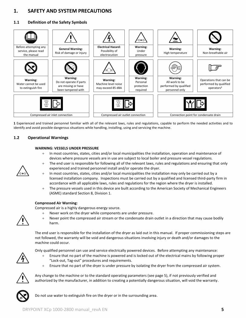
1. SAFETY AND SYSTEM PRECAUTIONS 1.1 Definition of the Safety Symbols
Before attempting any
service, please read the manual
General Warning: Risk of damage or injury
Electrical Hazard: Possibility of electrocution
Warning: Under
pressure
Warning: High temperature
Warning: Non-breathable air
Warning: Water cannot be used
to extinguish fire
Warning: Do not operate if parts
are missing or have been tampered with
Warning: Machine level noise may exceed 85 dBA
Warning: Personal
protection required
Warning: All work to be
performed by qualified personnel only
Operations that can be performed by qualified
operators1
Compressed air inlet connection Compressed air outlet connection Connection point for condensate drain
1 Experienced and trained personnel familiar with all of the relevant laws, rules and regulations, capable to perform the needed activities and to identify and avoid possible dangerous situations while handling, installing, using and servicing the machine.
1.2 Operational Warnings
WARNING: VESSELS UNDER PRESSURE
In most countries, states, cities and/or local municipalities the installation, operation and maintenance of devices where pressure vessels are in use are subject to local boiler and pressure vessel regulations.
The end user is responsible for following all of the relevant laws, rules and regulations and ensuring that only experienced and trained personnel install and/or operate the dryer.
In most countries, states, cities and/or local municipalities the installation may only be carried out by a licensed installation company. Inspections must be carried out by a qualified and licensed third-party firm in accordance with all applicable laws, rules and regulations for the region where the dryer is installed.
The pressure vessels used in this device are built according to the American Society of Mechanical Engineers (ASME) standard Section 8, Division 1.
Compressed Air Warning: Compressed air is a highly dangerous energy source.
Never work on the dryer while components are under pressure.
Never point the compressed air stream or the condensate drain outlet in a direction that may cause bodily harm.
The end user is responsible for the installation of the dryer as laid out in this manual. If proper commissioning steps are not followed, the warranty will be void and dangerous situations involving injury or death and/or damages to the machine could occur.
Only qualified personnel can use and service electrically powered devices. Before attempting any maintenance:
Ensure that no part of the machine is powered and is locked out of the electrical mains by following proper “Lock-out, Tag-out” procedures and requirements.
Ensure that no part of the dryer is under pressure by isolating the dryer from the compressed air system.
Any change to the machine or to the standard operating parameters (see page 5), if not previously verified and authorized by the manufacturer, in addition to creating a potentially dangerous situation, will void the warranty.
Do not use water to extinguish fire on the dryer or in the surrounding area.
ARIAAIR
LUFTAIR
DRYPOINT XCp 1000-2800 manual_revA EN 6
2. INSPECTION AND TRANSPORTATION All dryers are tested and inspected at the factory prior to shipping. Thoroughly inspect and verify the integrity of the packaging upon receipt and note any damage on the freight bill. Place the unit as close as possible to the installation point before unpacking the contents and inspect for concealed damage. Freight claims are to be filed with the carrier immediately and the manufacturer’s technical service department notified thereafter.
To move the packaged unit, we suggest the use of a suitable crane or forklift. We do not recommend moving the unit by any hand operated or manual mechanism.
Handle with care. Heavy blows could cause irreparable damage.
Even when packaged, keep the machine protected from severe weather.
The packaging materials are recyclable. Each material must be properly disposed in a manner complying with the rules and regulations of the local municipality government.
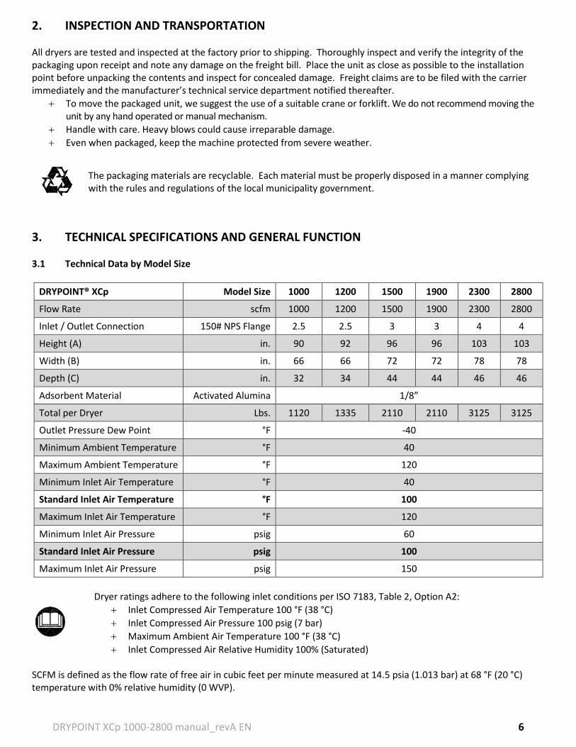
3. TECHNICAL SPECIFICATIONS AND GENERAL FUNCTION 3.1 Technical Data by Model Size
DRYPOINT® XCp Model Size 1000 1200 1500 1900 2300 2800
Total per Dryer Lbs. 1120 1335 2110 2110 3125 3125
Outlet Pressure Dew Point °F -40
Minimum Ambient Temperature °F 40
Maximum Ambient Temperature °F 120
Minimum Inlet Air Temperature °F 40
Standard Inlet Air Temperature °F 100
Maximum Inlet Air Temperature °F 120
Minimum Inlet Air Pressure psig 60
Standard Inlet Air Pressure psig 100
Maximum Inlet Air Pressure psig 150
Dryer ratings adhere to the following inlet conditions per ISO 7183, Table 2, Option A2:
Inlet Compressed Air Temperature 100 °F (38 °C)
Inlet Compressed Air Pressure 100 psig (7 bar)
Maximum Ambient Air Temperature 100 °F (38 °C)
Inlet Compressed Air Relative Humidity 100% (Saturated) SCFM is defined as the flow rate of free air in cubic feet per minute measured at 14.5 psia (1.013 bar) at 68 °F (20 °C) temperature with 0% relative humidity (0 WVP).
DRYPOINT XCp 1000-2800 manual_revA EN 7
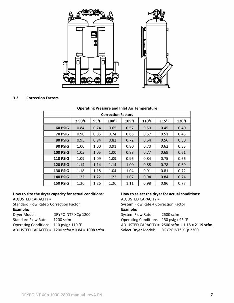
3.2 Correction Factors
Operating Pressure and Inlet Air Temperature Correction Factors
≤ 90°F 95°F 100°F 105°F 110°F 115°F 120°F
60 PSIG 0.84 0.74 0.65 0.57 0.50 0.45 0.40
70 PSIG 0.90 0.85 0.74 0.65 0.57 0.51 0.45
80 PSIG 0.95 0.94 0.82 0.72 0.64 0.56 0.50
90 PSIG 1.00 1.00 0.91 0.80 0.70 0.62 0.55
100 PSIG 1.05 1.05 1.00 0.88 0.77 0.69 0.61
110 PSIG 1.09 1.09 1.09 0.96 0.84 0.75 0.66
120 PSIG 1.14 1.14 1.14 1.00 0.88 0.78 0.69
130 PSIG 1.18 1.18 1.04 1.04 0.91 0.81 0.72
140 PSIG 1.22 1.22 1.22 1.07 0.94 0.84 0.74
150 PSIG 1.26 1.26 1.26 1.11 0.98 0.86 0.77
How to size the dryer capacity for actual conditions: How to select the dryer for actual conditions: ADJUSTED CAPACITY = ADJUSTED CAPACITY = Standard Flow Rate x Correction Factor System Flow Rate ÷ Correction Factor Example: Example: Dryer Model: DRYPOINT® XCp 1200 System Flow Rate: 2500 scfm Standard Flow Rate: 1200 scfm Operating Conditions: 130 psig / 95 °F Operating Conditions: 110 psig / 110 °F ADJUSTED CAPACITY = 2500 scfm ÷ 1.18 = 2119 scfm ADJUSTED CAPACITY = 1200 scfm x 0.84 = 1008 scfm Select Dryer Model: DRYPOINT® XCp 2300
DRYPOINT XCp 1000-2800 manual_revA EN 8
3.3 General Function The DRYPOINT® X heatless desiccant dryer series are fitted with two pressure vessels, positioned parallel to one another and filled with adsorption material (⅛” activated alumina as standard). While the compressed air is dried in one tower, the saturated desiccant is regenerated in the second. A minimal portion of the treated air is used for the regeneration process and expelled along with the condensate, through the exhaust silencers. The saturated inlet air is cycled through each of the two desiccant beds in an alternating sequence where one bed is on-line at full line pressure and flow, adsorbing the water vapor. This is the drying bed. The other bed is then considered to be in an off-line state at atmospheric pressure and is being regenerated by a depressurized portion of the dried, treated outlet air (purge air). This is the regenerating bed. The purge air is routed from the dry outlet air through the purge flow control valve, desiccant bed, purge exhaust valve and finally exhausted to atmosphere through exhaust silencers to finish the regeneration process. Purge air consumption is generally the highest cost involved with operating a heatless adsorption dryer and is non-recoverable. Therefore, the air system where the dryer is installed must account for this usage (approximately 15% of the inlet air flow averaged over the standard 5 min cycle). Just before the freshly regenerated bed is brought to an on-line state to become the drying bed, it is slowly pressurized from atmospheric pressure up to line pressure. This is the re-pressurization step that prevents desiccant bed fluidization (bed lifting) and dusting. The desiccant beds will now switch functions where the fresh desiccant bed is now drying and the saturated bed is now regenerating. This cycle will continue automatically unless the dryer is shut down. All desiccant dryers work using the principle of adsorption, which is the process by which water vapor is removed from the compressed air being dried. All desiccant material types are adversely affected by oil, aerosols, dirt, rust, scale and liquid water. If contaminated the desiccant material will lose its adsorption proprieties. Moreover during operation, the desiccant releases solid particles (as fine powder) that are particularly abrasive and can be extremely damaging to downstream components and users. For this reason, the dryer must be equipped with two high-efficiency CLEARPOINT® filters:
0.01 micron filtration grade coalescing pre-filter with differential pressure gauge and either a float drain or BEKOMAT®
1.0 micron filtration grade particulate post-filter (differential gauge optional) and with a manual drain.
DRYPOINT XCp 1000-2800 manual_revA EN 9
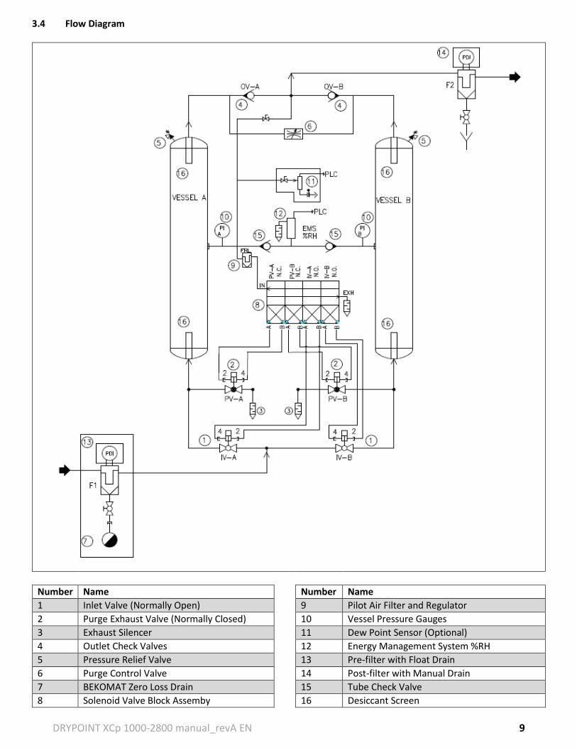
3.4 Flow Diagram
Number Name Number Name
1 Inlet Valve (Normally Open) 9 Pilot Air Filter and Regulator
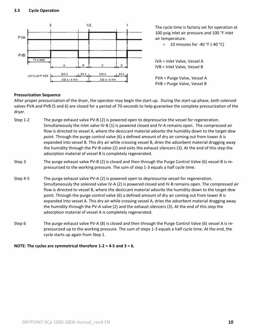
The cycle time is factory set for operation at 100 psig inlet air pressure and 100 °F inlet air temperature.
10 minutes for -40 °F (-40 °C) IVA = Inlet Valve, Vessel A IVB = Inlet Valve, Vessel B PVA = Purge Valve, Vessel A PVB = Purge Valve, Vessel B
Pressurization Sequence After proper pressurization of the dryer, the operator may begin the start-up. During the start-up phase, both solenoid valves PVA and PVB (5 and 6) are closed for a period of 70-seconds to help guarantee the complete pressurization of the dryer.
Step 1-2 The purge exhaust valve PV-B (2) is powered open to depressurize the vessel for regeneration. Simultaneously the inlet valve IV-B (1) is powered closed and IV-A remains open. The compressed air flow is directed to vessel A, where the desiccant material adsorbs the humidity down to the target dew point. Through the purge control valve (6) a defined amount of dry air coming out from tower A is expanded into vessel B. This dry air while crossing vessel B, dries the adsorbent material dragging away the humidity through the PV-B valve (2) and exits the exhaust silencers (3). At the end of this step the adsorption material of vessel B is completely regenerated.
Step 3 The purge exhaust valve PV-B (2) is closed and then through the Purge Control Valve (6) vessel B is re-pressurized to the working pressure. The sum of step 1-3 equals a half cycle time.
Step 4-5 The purge exhaust valve PV-A (2) is powered open to depressurize vessel for regeneration.
Simultaneously the solenoid valve IV-A (2) is powered closed and IV-B remains open. The compressed air flow is directed to vessel B, where the desiccant material adsorbs the humidity down to the target dew point. Through the purge control valve (6) a defined amount of dry air coming out from tower B is expanded into vessel A. This dry air while crossing vessel A, dries the adsorbent material dragging away the humidity through the PV-A valve (2) and the exhaust silencers (3). At the end of this step the adsorption material of vessel A is completely regenerated.
Step 6 The purge exhaust valve PV-A (8) is closed and then through the Purge Control Valve (6) vessel A is re-
pressurized up to the working pressure. The sum of steps 1-3 equals a half cycle time. At the end, the cycle starts up again from Step 1.
NOTE: The cycles are symmetrical therefore 1-2 = 4-5 and 3 = 6.
DRYPOINT XCp 1000-2800 manual_revA EN 11
4. INSTALLATION 4.1 Design and Use of the Dryer This dryer has been designed, manufactured and tested to be used only to separate the humidity normally contained in compressed air, any other use is considered to be improper. The manufacturer is not responsible for any problems arising from the improper use of this machine. The end user, in any and all cases, is responsible for any resulting damages. Moreover, the correct use of this machine requires the verification of certain installation conditions, in particular:
Voltage and frequency of the electrical power supplied
Pressure, temperature, flow rate and chemical composition of the incoming compressed air
Ambient temperatures The dryer is supplied as tested and fully assembled. The only operation left for the end user is the connection to the plant and adjustment of the purge rate in compliance with the instructions given in this manual. Factory settings are at nominal conditions at 100 psig and the stated model flow rate (see page 5).
The purpose of the machine is the separation of water vapor that is present in compressed air. It is not intended to separate oil or other contaminants that are present in compressed air. The dried compressed air output from this dryer cannot be used for respiration purposes of any kind.
4.2 Location and Installation
Serious consideration should be given when selecting the installation site for the dryer, as an improper location could directly affect the proper operation of the dryer. This unit is not suitable to be used in explosive atmospheres, where risk of fire could exist, in the presence of gaseous or solid pollutants or in outdoor applications or areas exposed to the elements.
Do not use water to extinguish fire on the dryer or in the surrounding area.
Machine level noise could be higher than 85 dBA. Install the unit in a dedicated area where people are not normally present. The installer and/or end user is responsible for the correct installation of the dryer in order to prevent excessive noise exposure in the work environment. The installer and/or end user is responsible for installing proper safety signage at the installation site.
Technicians that service the machine must wear hearing and eye protection while servicing the dryer. Each employee must select a proper personal protection equipment (PPE) hearing protector such as earmuffs, ear canal caps or earplugs in order to prevent permanent hearing damage or loss.
Minimum Installation Location Requirements:
Select a clean, dry room that is free of dust and protected from atmospheric disturbances
The location must be smooth, horizontally level, able to bear the weight of the dryer and vibration free
Minimum ambient temperature of +40 °F
Maximum ambient temperature of +120 °F
Allow a clearance of at least 3’ on all sides of the dryer in order easily facilitate all maintenance needs
The dryer is not required to be anchored to the supporting surface
Coalescing pre-filter with drain must be installed
The location of an air receiver tank will vary depending on compressor type and application conditions
Incorrect installation may void warranty.
DRYPOINT XCp 1000-2800 manual_revA EN 12
NOTE: All piping and electrical connections should be inspected prior to installation to ensure they have maintained their integrity during shipping and placement of the dryer. First, make the initial connections as follows:
1. Inlet piping including an isolation valve 2. Outlet piping including an isolation valve 3. Coalescing pre-filter and particulate post-filter
We recommend the dryer be installed with a 0.01 micron CLEARPOINT® coalescing pre-filter at the inlet and a 1.0 micron CLEARPOINT® particulate post-filter at the outlet. It is recommended to install both 5.0 micron and 1.0 micron filters upstream of the dryer in order to maintain the operational lifespan of the inlet filter to the dryer. In addition, we recommend the use of a BEKOMAT® zero air loss drain on the pre-filter and at all other condensate collection points, especially those upstream of the dryer.
Locate the coalescing pre-filter as close to the dryer as possible while still maintaining sufficient space for routine maintenance and service. Inlet air entering the dryer must pass through a coalescing pre-filter in order remove entrained condensate and oil to prevent fouling of the desiccant and maintain standard operation. Any liquid condensate entering the desiccant bed will lead to overloading of the dryer, poor dew point performance and rapid deterioration of the desiccant material. Any oil entering the desiccant bed may permanently reduce the capacity of the desiccant material.
Desiccant dust traveling downstream of the dryer may cause contamination and/or accelerated wear to other components and equipment. Therefore, a particulate post-filter should be installed to prevent desiccant dust from traveling downstream. Activated alumina is considered a nuisance dust and proper precautions should be taken when handling desiccant (refer to applicable MSDS sheet).
4. IMPORTANT! Bypass piping is necessary. Only bubble tight valves should be used. 5. Make the required electrical connections; please refer the type plate of your dryer. The end user is
responsible for providing short circuit protection for the dryer. 6. Points of access should be provided upstream and downstream of the dryer for periodic monitoring of
dew point, pressure and temperature prior to finalizing the installation. Taking periodic dew point measurements just downstream of the dryer gives the best indication of whether the dryer is performing optimally. We recommend using METPOINT® instrumentation to ensure accurate measurements.
7. All piping must be adequately supported and at least of equal size to the dryer connections.
Before any attempt is made to operate the dryer, the operator must thoroughly read and understand this installation and operation manual.
DRYPOINT XCp 1000-2800 manual_revA EN 13
4.3 Optimal Installation Diagram
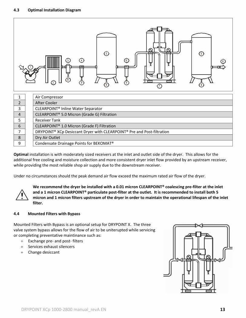
1 Air Compressor
2 After Cooler
3 CLEARPOINT® Inline Water Separator
4 CLEARPOINT® 5.0 Micron (Grade G) Filtration
5 Receiver Tank
6 CLEARPOINT® 1.0 Micron (Grade F) Filtration
7 DRYPOINT® XCp Desiccant Dryer with CLEARPOINT® Pre and Post-filtration
8 Dry Air Outlet
9 Condensate Drainage Points for BEKOMAT®
Optimal installation is with moderately sized receivers at the inlet and outlet side of the dryer. This allows for the additional free cooling and moisture collection and more consistent dryer inlet flow provided by an upstream receiver, while providing the most reliable shop air supply due to the downstream receiver. Under no circumstances should the peak demand air flow exceed the maximum rated air flow of the dryer.
We recommend the dryer be installed with a 0.01 micron CLEARPOINT® coalescing pre-filter at the inlet and a 1 micron CLEARPOINT® particulate post-filter at the outlet. It is recommended to install both 5 micron and 1 micron filters upstream of the dryer in order to maintain the operational lifespan of the inlet filter.
4.4 Mounted Filters with Bypass Mounted Filters with Bypass is an optional setup for DRYPOINT X. The three valve system bypass allows for the flow of air to be uniterupted while servicing or completing preventative maintinance such as:
Exchange pre- and post- filters
Services exhaust sIlencers
Change desiccant
DRYPOINT XCp 1000-2800 manual_revA EN 14
5. DRYER OPERATION 5.1 START-UP 5.1.1 Verification Prior to Start-up
Verify that the operating parameters match with the acceptable ranges indicated on the data plate of the dryer (voltage, frequency, air pressure, air temperature, ambient temperature, etc.). This is not the same as the ASME UW plate on the vessels and may be lower than what is stamped on the ASME UW plate.
Before delivery, each dryer is submitted to accurate tests simulating real operating conditions. Nevertheless, the unit could be damaged during transportation. Therefore, we suggest checking the integrity of the dryer upon arrival (see page 4) and observing the dryer during the first hours of operation.
The start-up must be performed by qualified personnel only. It is mandatory that the engineer in charge will verify safe operational conditions complying with the local safety and accident prevention requirements.
The same engineer will be responsible for the proper and safe operation of the dryer. Never operate the dryer if all panels are not properly in place or if any componentry is missing or appears damaged.
Service to be performed by qualified personnel only. The end user is responsible to ensure that the dryer will never be operated under pressure that exceeds the maximum pressure rating of the unit. Operating the dryer at a pressure higher than the maximum rating could be dangerous for both the operator and the machine.
The inlet air temperature and air flow rate entering the dryer must be within the limits indicated on the data plate.
Installation precautions must be taken in order to limit the vibration that can occur during the operation of the dryer. Therefore, we recommend using flexible connecting pipes that are able to insulate the dryer from possible vibrations originating from the pipe line.
The connection to the main power is to be carried out by qualified personnel, and the safety protocol must comply with local rules and laws.
Before connecting the unit to the electric power, verify that the voltage and the frequency available on the mains
correspond to the data on the data plate of the dryer. In terms of voltage, a 5% tolerance is acceptable. The wire size feeding the dryer must comply with the consumption of the dryer, while keeping into account also the ambient temperature, the conditions of the main power junction box, the length of the wire, and the requirements enforced by the local power company.
It is mandatory to ensure the connection to the ground terminal.
The condensate is discharged at the same pressure as the air entering the dryer. Never point the condensate drain discharge in a direction that may cause bodily harm.
Connect and properly fasten the condensate drain to a collection system or container. The outlet condensate hose cannot be connected to pressurized systems.
DO NOT DISPOSE OF CONDENSATE INTO THE ENVIRONMENT The condensate collected in the dryer contains oil particles released into the air stream by the compressor. Dispose of the condensate in a manner compliant with all local, state and Federal rules and regulations.
DRYPOINT XCp 1000-2800 manual_revA EN 15
We highly recommend the installation of either a QWIK-PURE® or ÖWAMAT® oil-water separator at the final collection point for all condensate discharge lines within the facility (i.e. from the main header).
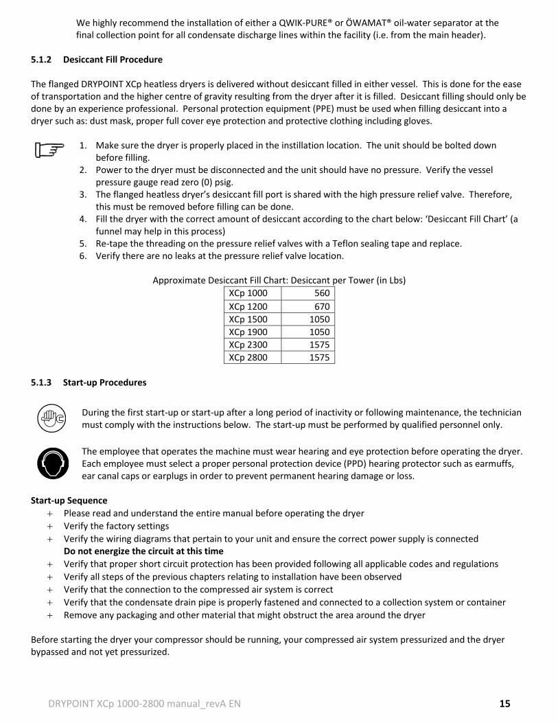
5.1.2 Desiccant Fill Procedure The flanged DRYPOINT XCp heatless dryers is delivered without desiccant filled in either vessel. This is done for the ease of transportation and the higher centre of gravity resulting from the dryer after it is filled. Desiccant filling should only be done by an experience professional. Personal protection equipment (PPE) must be used when filling desiccant into a dryer such as: dust mask, proper full cover eye protection and protective clothing including gloves.
1. Make sure the dryer is properly placed in the instillation location. The unit should be bolted down before filling.
2. Power to the dryer must be disconnected and the unit should have no pressure. Verify the vessel pressure gauge read zero (0) psig.
3. The flanged heatless dryer’s desiccant fill port is shared with the high pressure relief valve. Therefore, this must be removed before filling can be done.
4. Fill the dryer with the correct amount of desiccant according to the chart below: ‘Desiccant Fill Chart’ (a funnel may help in this process)
5. Re-tape the threading on the pressure relief valves with a Teflon sealing tape and replace. 6. Verify there are no leaks at the pressure relief valve location.
Approximate Desiccant Fill Chart: Desiccant per Tower (in Lbs)
XCp 1000 560
XCp 1200 670
XCp 1500 1050
XCp 1900 1050
XCp 2300 1575
XCp 2800 1575
5.1.3 Start-up Procedures
During the first start-up or start-up after a long period of inactivity or following maintenance, the technician must comply with the instructions below. The start-up must be performed by qualified personnel only.
The employee that operates the machine must wear hearing and eye protection before operating the dryer. Each employee must select a proper personal protection device (PPD) hearing protector such as earmuffs, ear canal caps or earplugs in order to prevent permanent hearing damage or loss.
Start-up Sequence
Please read and understand the entire manual before operating the dryer
Verify the factory settings
Verify the wiring diagrams that pertain to your unit and ensure the correct power supply is connected Do not energize the circuit at this time
Verify that proper short circuit protection has been provided following all applicable codes and regulations
Verify all steps of the previous chapters relating to installation have been observed
Verify that the connection to the compressed air system is correct
Verify that the condensate drain pipe is properly fastened and connected to a collection system or container
Remove any packaging and other material that might obstruct the area around the dryer Before starting the dryer your compressor should be running, your compressed air system pressurized and the dryer bypassed and not yet pressurized.
DRYPOINT XCp 1000-2800 manual_revA EN 16
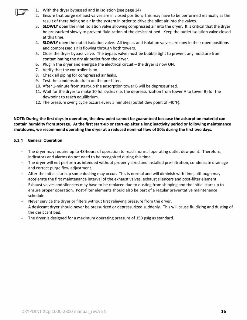
1. With the dryer bypassed and in isolation (see page 14) 2. Ensure that purge exhaust valves are in closed position; this may have to be performed manually as the
result of there being no air in the system in order to drive the pilot air into the valves. 3. SLOWLY open the inlet isolation valve allowing compressed air into the dryer. It is critical that the dryer
be pressurized slowly to prevent fluidization of the desiccant bed. Keep the outlet isolation valve closed at this time.
4. SLOWLY open the outlet isolation valve. All bypass and isolation valves are now in their open positions and compressed air is flowing through both towers.
5. Close the dryer bypass valve. The bypass valve must be bubble tight to prevent any moisture from contaminating the dry air outlet from the dryer.
6. Plug in the dryer and energize the electrical circuit – the dryer is now ON. 7. Verify that the controller is on. 8. Check all piping for compressed air leaks. 9. Test the condensate drain on the pre-filter. 10. After 1-minute from start-up the adsorption tower B will be depressurized. 11. Wait for the dryer to make 10 full cycles (i.e. the depressurization from tower A to tower B) for the
dewpoint to reach equilibrium. 12. The pressure swing cycle occurs every 5 minutes (outlet dew point of -40°F).
NOTE: During the first days in operation, the dew point cannot be guaranteed because the adsorption material can contain humidity from storage. At the first start-up or start-up after a long inactivity period or following maintenance shutdowns, we recommend operating the dryer at a reduced nominal flow of 50% during the first two days. 5.1.4 General Operation
The dryer may require up to 48-hours of operation to reach normal operating outlet dew point. Therefore, indicators and alarms do not need to be recognized during this time.
The dryer will not perform as intended without properly sized and installed pre-filtration, condensate drainage and correct purge flow adjustment.
After the initial start-up some dusting may occur. This is normal and will diminish with time, although may accelerate the first maintenance interval of the exhaust valves, exhaust silencers and post-filter element.
Exhaust valves and silencers may have to be replaced due to dusting from shipping and the initial start-up to ensure proper operation. Post-filter elements should also be part of a regular preventative maintenance schedule.
Never service the dryer or filters without first relieving pressure from the dryer.
A desiccant dryer should never be pressurized or depressurized suddenly. This will cause fluidizing and dusting of the desiccant bed.
The dryer is designed for a maximum operating pressure of 150 psig as standard.
DRYPOINT XCp 1000-2800 manual_revA EN 17
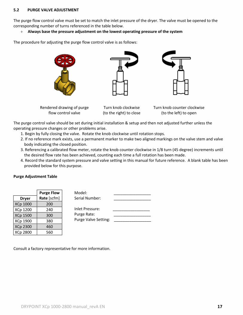
5.2 PURGE VALVE ADJUSTMENT
The purge flow control valve must be set to match the inlet pressure of the dryer. The valve must be opened to the corresponding number of turns referenced in the table below.
Always base the pressure adjustment on the lowest operating pressure of the system The procedure for adjusting the purge flow control valve is as follows:
Rendered drawing of purge flow control valve
Turn knob clockwise (to the right) to close
Turn knob counter clockwise (to the left) to open
The purge control valve should be set during initial installation & setup and then not adjusted further unless the operating pressure changes or other problems arise.
1. Begin by fully closing the valve. Rotate the knob clockwise until rotation stops. 2. If no reference mark exists, use a permanent marker to make two aligned markings on the valve stem and valve
body indicating the closed position. 3. Referencing a calibrated flow meter, rotate the knob counter clockwise in 1/8 turn (45 degree) increments until
the desired flow rate has been achieved, counting each time a full rotation has been made. 4. Record the standard system pressure and valve setting in this manual for future reference. A blank table has been
provided below for this purpose. Purge Adjustment Table
Consult a factory representative for more information.
Users operating the machine must wear hearing and eye protection. Each employee must select a proper personal protection device (PPD) hearing protector such as earmuffs, ear canal caps or earplugs in order to prevent permanent hearing damage or loss.
Isolation 1. Allow the dryer to reach its re-pressurization step and fully re-pressurize. Therefore, both vessels should
be fully pressurized. 2. Once fully re-pressurized, remove power from the dryer. 3. Open the bypass valve. 4. Close the outlet isolation valve. 5. Close the inlet isolation valve.
Depressurization and Shut Down
1. Open the bypass valve. 2. Close the outlet isolation valve. 3. Close the inlet isolation valve. 4. Allow the dryer to continue to run. During the normal operating cycle both towers will blow down and
depressurize. 5. Disconnect the power to the dryer. 6. Open the manual ball valves on any filters with manual ball valves to allow full depressurization. Also,
leave manual ball valves on filter open during maintenance and service.
IMPORTANT! Always remove all pressure and disconnect all power before servicing the dryer.
To restart the dryer, follow the start-up procedure in section 5.1, START-UP, on pages 12-13.
DRYPOINT XCp 1000-2800 manual_revA EN 19
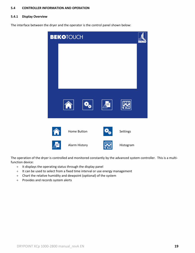
5.4 CONTROLLER INFORMATION AND OPERATION 5.4.1 Display Overview The interface between the dryer and the operator is the control panel shown below:
Home Button
Settings
Alarm History
Histogram
The operation of the dryer is controlled and monitored constantly by the advanced system controller. This is a multi-function device:
It displays the operating status through the display panel
It can be used to select from a fixed time interval or use energy management
Chart the relative humidity and dewpoint (optional) of the system
Provides and records system alerts
DRYPOINT XCp 1000-2800 manual_revA EN 20
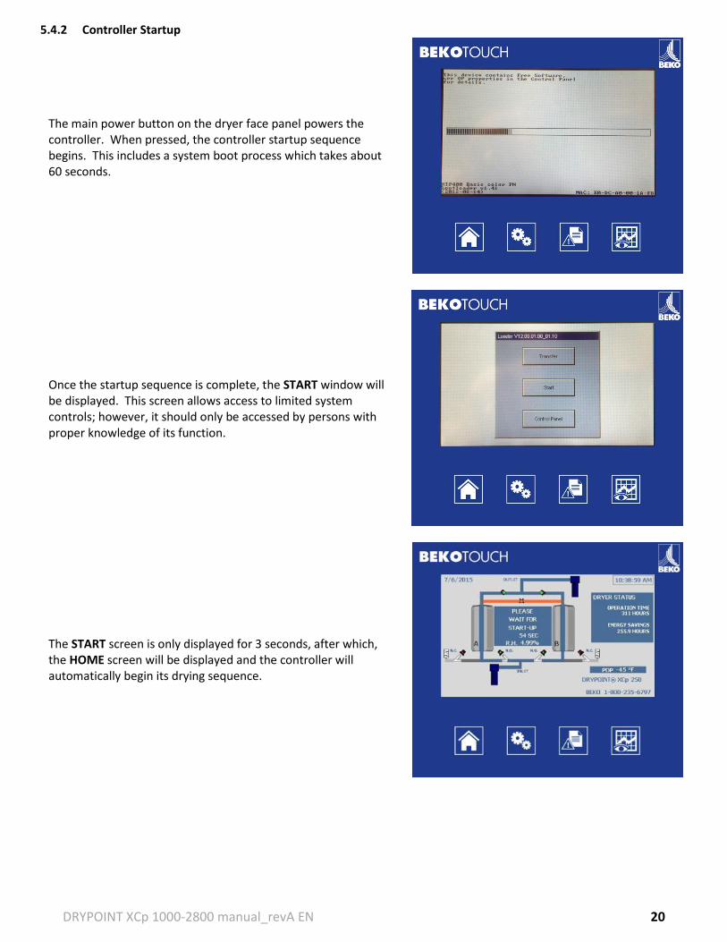
5.4.2 Controller Startup
The main power button on the dryer face panel powers the controller. When pressed, the controller startup sequence begins. This includes a system boot process which takes about 60 seconds.
Once the startup sequence is complete, the START window will be displayed. This screen allows access to limited system controls; however, it should only be accessed by persons with proper knowledge of its function.
The START screen is only displayed for 3 seconds, after which, the HOME screen will be displayed and the controller will automatically begin its drying sequence.
DRYPOINT XCp 1000-2800 manual_revA EN 21
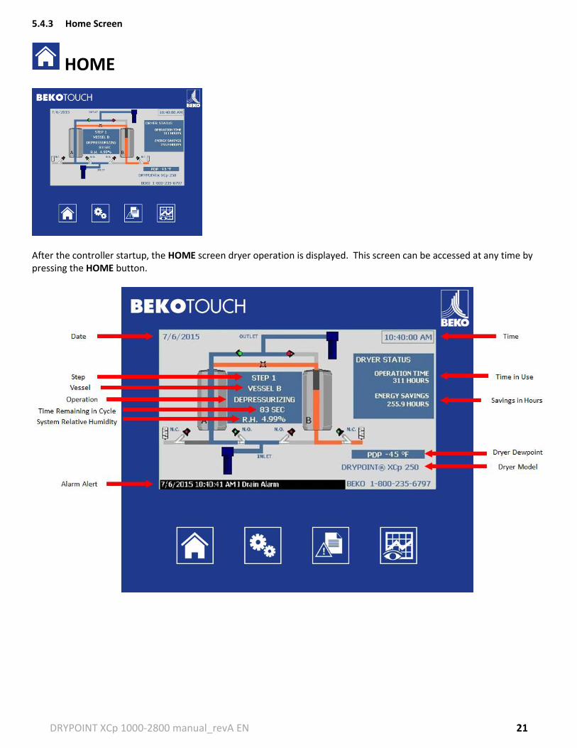
5.4.3 Home Screen
HOME
After the controller startup, the HOME screen dryer operation is displayed. This screen can be accessed at any time by pressing the HOME button.
DRYPOINT XCp 1000-2800 manual_revA EN 22
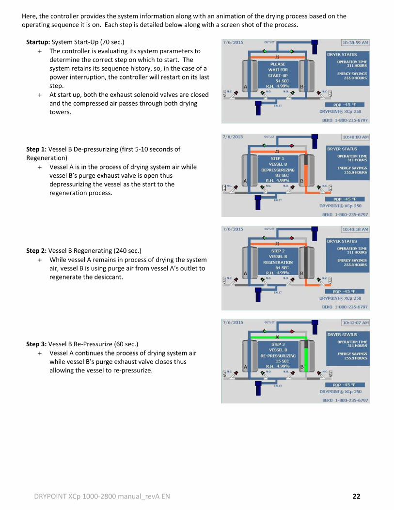
Here, the controller provides the system information along with an animation of the drying process based on the operating sequence it is on. Each step is detailed below along with a screen shot of the process.
Startup: System Start-Up (70 sec.)
The controller is evaluating its system parameters to determine the correct step on which to start. The system retains its sequence history, so, in the case of a power interruption, the controller will restart on its last step.
At start up, both the exhaust solenoid valves are closed and the compressed air passes through both drying towers.
Step 1: Vessel B De-pressurizing (first 5-10 seconds of Regeneration)
Vessel A is in the process of drying system air while vessel B’s purge exhaust valve is open thus depressurizing the vessel as the start to the regeneration process.
Step 2: Vessel B Regenerating (240 sec.)
While vessel A remains in process of drying the system air, vessel B is using purge air from vessel A’s outlet to regenerate the desiccant.
Step 3: Vessel B Re-Pressurize (60 sec.)
Vessel A continues the process of drying system air while vessel B’s purge exhaust valve closes thus allowing the vessel to re-pressurize.
DRYPOINT XCp 1000-2800 manual_revA EN 23
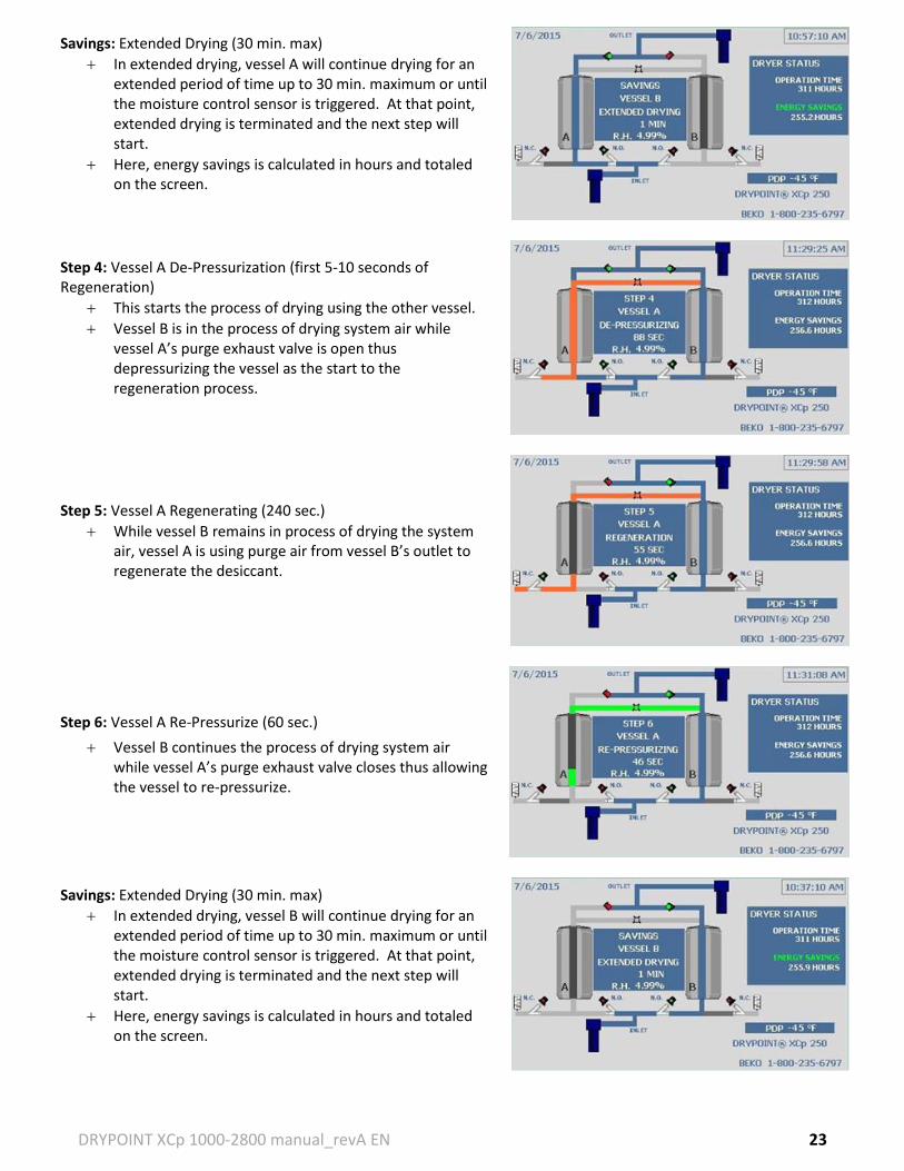
Savings: Extended Drying (30 min. max)
In extended drying, vessel A will continue drying for an extended period of time up to 30 min. maximum or until the moisture control sensor is triggered. At that point, extended drying is terminated and the next step will start.
Here, energy savings is calculated in hours and totaled on the screen.
Step 4: Vessel A De-Pressurization (first 5-10 seconds of Regeneration)
This starts the process of drying using the other vessel.
Vessel B is in the process of drying system air while vessel A’s purge exhaust valve is open thus depressurizing the vessel as the start to the regeneration process.
Step 5: Vessel A Regenerating (240 sec.)
While vessel B remains in process of drying the system air, vessel A is using purge air from vessel B’s outlet to regenerate the desiccant.
Step 6: Vessel A Re-Pressurize (60 sec.)
Vessel B continues the process of drying system air while vessel A’s purge exhaust valve closes thus allowing the vessel to re-pressurize.
Savings: Extended Drying (30 min. max)
In extended drying, vessel B will continue drying for an extended period of time up to 30 min. maximum or until the moisture control sensor is triggered. At that point, extended drying is terminated and the next step will start.
Here, energy savings is calculated in hours and totaled on the screen.
DRYPOINT XCp 1000-2800 manual_revA EN 24
After this second Savings step, the controller will continue back to Step 1. Note that the Savings step function is only applicable if it has been enabled in SETTINGS (under the Energy Management option). To enable this, refer to the SETTINGS section of the manual.
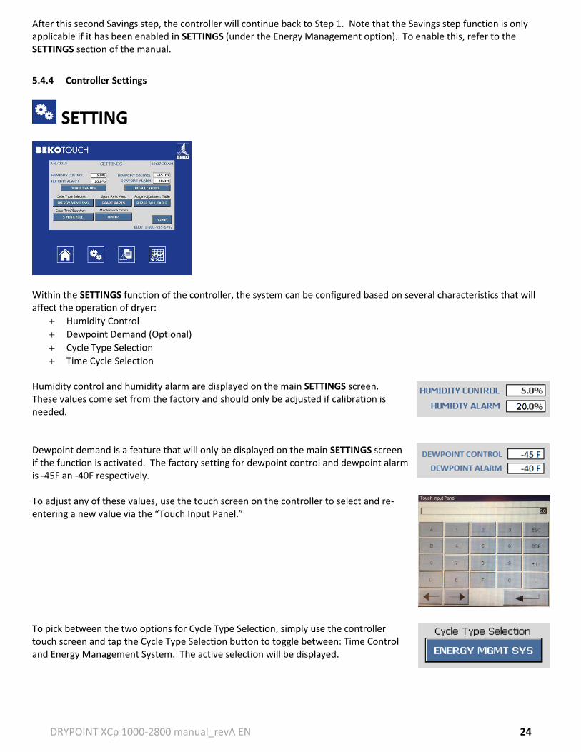
5.4.4 Controller Settings
SETTING
Within the SETTINGS function of the controller, the system can be configured based on several characteristics that will affect the operation of dryer:
Humidity Control
Dewpoint Demand (Optional)
Cycle Type Selection
Time Cycle Selection Humidity control and humidity alarm are displayed on the main SETTINGS screen. These values come set from the factory and should only be adjusted if calibration is needed. Dewpoint demand is a feature that will only be displayed on the main SETTINGS screen if the function is activated. The factory setting for dewpoint control and dewpoint alarm is -45F an -40F respectively. To adjust any of these values, use the touch screen on the controller to select and re-entering a new value via the “Touch Input Panel.” To pick between the two options for Cycle Type Selection, simply use the controller touch screen and tap the Cycle Type Selection button to toggle between: Time Control and Energy Management System. The active selection will be displayed.
DRYPOINT XCp 1000-2800 manual_revA EN 25
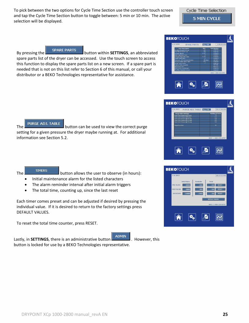
To pick between the two options for Cycle Time Section use the controller touch screen and tap the Cycle Time Section button to toggle between: 5 min or 10 min. The active selection will be displayed.
By pressing the button within SETTINGS, an abbreviated spare parts list of the dryer can be accessed. Use the touch screen to access this function to display the spare parts list on a new screen. If a spare part is needed that is not on this list refer to Section 6 of this manual, or call your distributor or a BEKO Technologies representative for assistance.
The button can be used to view the correct purge setting for a given pressure the dryer maybe running at. For additional information see Section 5.2.
The button allows the user to observe (in hours):
Initial maintenance alarm for the listed characters
The alarm reminder interval after initial alarm triggers
The total time, counting up, since the last reset Each timer comes preset and can be adjusted if desired by pressing the individual value. If it is desired to return to the factory settings press DEFAULT VALUES. To reset the total time counter, press RESET.
Lastly, in SETTINGS, there is an administrative button . However, this button is locked for use by a BEKO Technologies representative.
DRYPOINT XCp 1000-2800 manual_revA EN 26
5.4.5 Alarm History
ALARM HISTORY
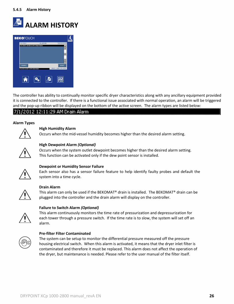
The controller has ability to continually monitor specific dryer characteristics along with any ancillary equipment provided it is connected to the controller. If there is a functional issue associated with normal operation, an alarm will be triggered and the pop-up ribbon will be displayed on the bottom of the active screen. The alarm types are listed below:
Alarm Types
High Humidity Alarm
Occurs when the mid-vessel humidity becomes higher than the desired alarm setting.
High Dewpoint Alarm (Optional)
Occurs when the system outlet dewpoint becomes higher than the desired alarm setting. This function can be activated only if the dew point sensor is installed.
Dewpoint or Humidity Sensor Failure Each sensor also has a sensor failure feature to help identify faulty probes and default the system into a time cycle.
Drain Alarm This alarm can only be used if the BEKOMAT® drain is installed. The BEKOMAT® drain can be plugged into the controller and the drain alarm will display on the controller.
Failure to Switch Alarm (Optional) This alarm continuously monitors the time rate of pressurization and depressurization for each tower through a pressure switch. If the time rate is to slow, the system will set off an alarm.
Pre-filter Filter Contaminated The system can be setup to monitor the differential pressure measured off the pressure housing electrical switch. When this alarm is activated, it means that the dryer inlet filter is contaminated and therefore it must be replaced. This alarm does not affect the operation of the dryer, but maintenance is needed. Please refer to the user manual of the filter itself.
DRYPOINT XCp 1000-2800 manual_revA EN 27
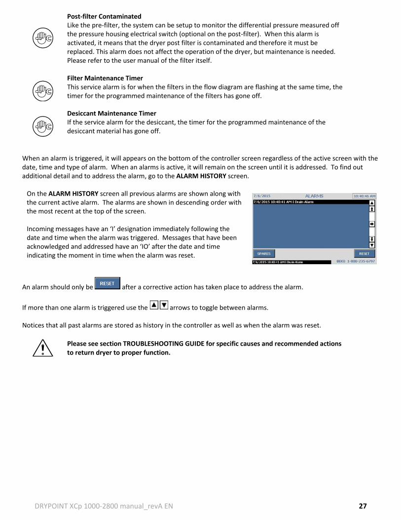
When an alarm is triggered, it will appears on the bottom of the controller screen regardless of the active screen with the date, time and type of alarm. When an alarms is active, it will remain on the screen until it is addressed. To find out additional detail and to address the alarm, go to the ALARM HISTORY screen.
On the ALARM HISTORY screen all previous alarms are shown along with the current active alarm. The alarms are shown in descending order with the most recent at the top of the screen. Incoming messages have an ‘I’ designation immediately following the date and time when the alarm was triggered. Messages that have been acknowledged and addressed have an ‘IO’ after the date and time indicating the moment in time when the alarm was reset.
An alarm should only be after a corrective action has taken place to address the alarm.
If more than one alarm is triggered use the arrows to toggle between alarms. Notices that all past alarms are stored as history in the controller as well as when the alarm was reset.
Post-filter Contaminated Like the pre-filter, the system can be setup to monitor the differential pressure measured off the pressure housing electrical switch (optional on the post-filter). When this alarm is activated, it means that the dryer post filter is contaminated and therefore it must be replaced. This alarm does not affect the operation of the dryer, but maintenance is needed. Please refer to the user manual of the filter itself.
Filter Maintenance Timer This service alarm is for when the filters in the flow diagram are flashing at the same time, the timer for the programmed maintenance of the filters has gone off.
Desiccant Maintenance Timer If the service alarm for the desiccant, the timer for the programmed maintenance of the desiccant material has gone off.
Please see section TROUBLESHOOTING GUIDE for specific causes and recommended actions to return dryer to proper function.
DRYPOINT XCp 1000-2800 manual_revA EN 28
5.4.6 Histogram
HISTOGRAM
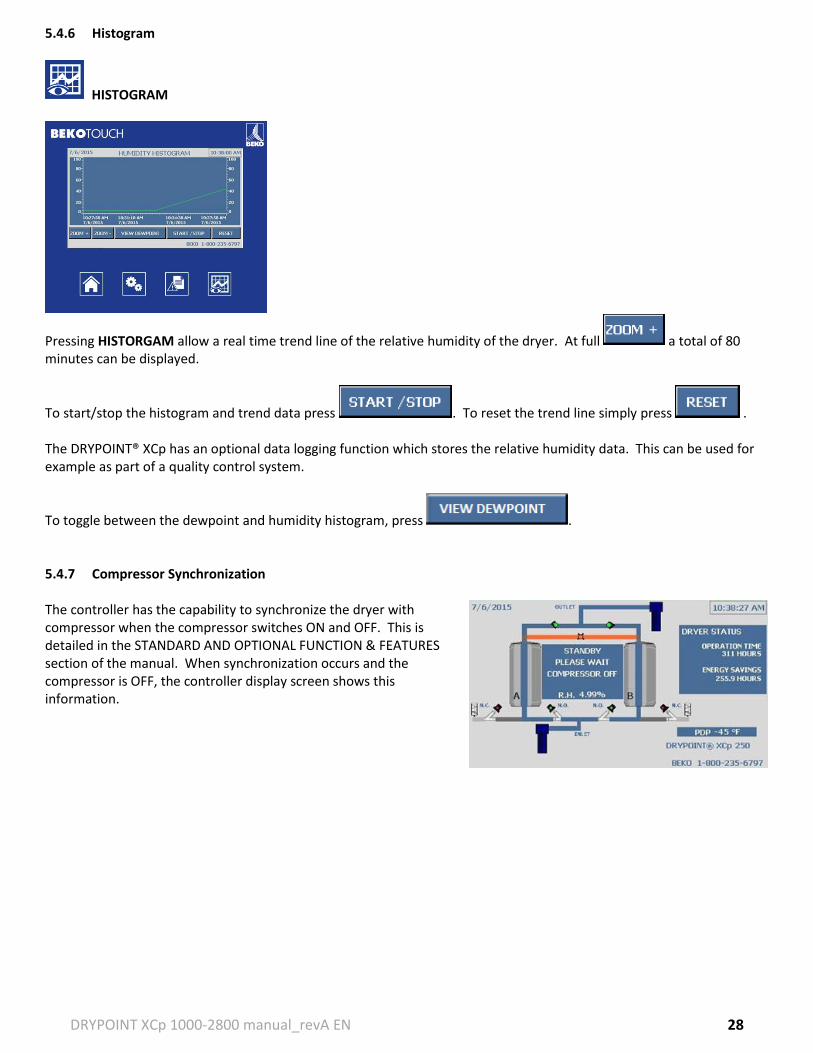
Pressing HISTORGAM allow a real time trend line of the relative humidity of the dryer. At full a total of 80 minutes can be displayed.
To start/stop the histogram and trend data press . To reset the trend line simply press . The DRYPOINT® XCp has an optional data logging function which stores the relative humidity data. This can be used for example as part of a quality control system.
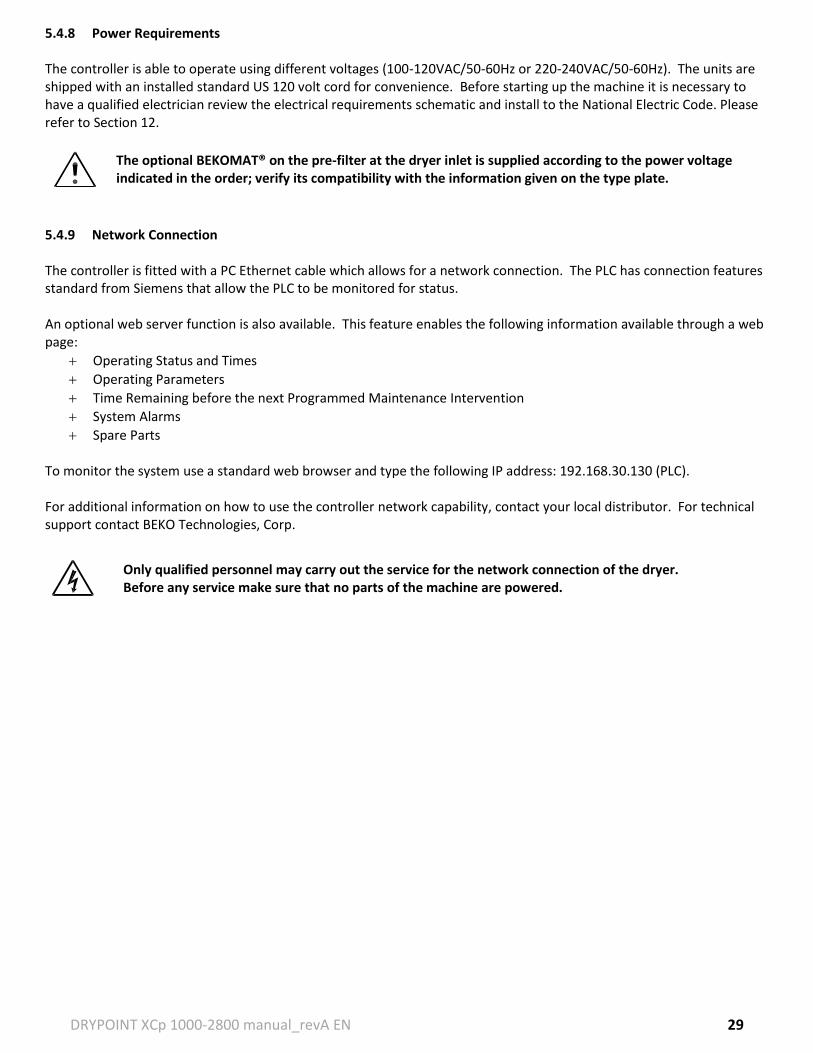
To toggle between the dewpoint and humidity histogram, press . 5.4.7 Compressor Synchronization The controller has the capability to synchronize the dryer with compressor when the compressor switches ON and OFF. This is detailed in the STANDARD AND OPTIONAL FUNCTION & FEATURES section of the manual. When synchronization occurs and the compressor is OFF, the controller display screen shows this information.
DRYPOINT XCp 1000-2800 manual_revA EN 29
5.4.8 Power Requirements The controller is able to operate using different voltages (100-120VAC/50-60Hz or 220-240VAC/50-60Hz). The units are shipped with an installed standard US 120 volt cord for convenience. Before starting up the machine it is necessary to have a qualified electrician review the electrical requirements schematic and install to the National Electric Code. Please refer to Section 12.
The optional BEKOMAT® on the pre-filter at the dryer inlet is supplied according to the power voltage indicated in the order; verify its compatibility with the information given on the type plate.
5.4.9 Network Connection The controller is fitted with a PC Ethernet cable which allows for a network connection. The PLC has connection features standard from Siemens that allow the PLC to be monitored for status. An optional web server function is also available. This feature enables the following information available through a web page:
Operating Status and Times
Operating Parameters
Time Remaining before the next Programmed Maintenance Intervention
System Alarms
Spare Parts To monitor the system use a standard web browser and type the following IP address: 192.168.30.130 (PLC). For additional information on how to use the controller network capability, contact your local distributor. For technical support contact BEKO Technologies, Corp.
Only qualified personnel may carry out the service for the network connection of the dryer. Before any service make sure that no parts of the machine are powered.
DRYPOINT XCp 1000-2800 manual_revA EN 30
5.5 STANDARD AND OPTIONAL FEATURES 5.5.1 Humidity Control (Standard) Humidity control comes as a standard programmable function on the DRYPOINT® XCp line of dryers providing the unit with an energy management function and to provide early moisture detection within the desiccant bed. The energy management function can be used to save energy for low load hours or during times of year with lower ambient temperatures or pressure dewpoint. The high moisture detection protects the desiccant bed from oversaturation. Humidity control utilizes a humidity sensor located within a sampling chamber that monitors the mid tower compressed air from of the online drying vessel. The humidity sensor continuously checks the vessel to see if the dryer’s desiccant has a moisture level below the humidity control set point. If the humidity is below the set point, the controller program will extend the drying cycle on that vessel thus saving energy by not switching vessels and using purging air. The system controller allows for a maximum of 30 minutes of energy savings per vessel before it is forced to switch in the event a sensor anomaly occurs. If the humidity in the vessel is too high, above the alarm value, it will trigger a minor alarm in the system. This feature is to protect the bed from oversaturation and to provide the customer with some means of energy savings. Under partial load conditions there are no adjustments to the target humidity needed. 5.5.2 Dewpoint Demand (Optional) Dewpoint demand comes as optional programmable function on the DRYPOINT® XCp line of dryers in order to provide the unit with an additional energy management function and real time dewpoint monitoring. The dewpoint monitoring is done through a METPOINT DPM dewpoint polymer sensor located at the outlet of the dryer. Dewpoint control is the target dew point of the dryer; the factory setting and recommendation is -45F. Below this value, the controller program will work alongside humidity control to provide energy saving with the dryer. The dewpoint alarm is the setting at which the controller will go into alarm if the value goes above that number; the factory setting and recommendation is -40F. Above this value, the high dewpoint minor alarm will trigger. Dewpoint demand differs from humidity control in that, dew point demand monitors the outlet performance while humidity control monitors the humidity mid- vessel. While dewpoint demand is a more accurate measurement and measure the dewpoint of air leaving the dryer, when an unacceptably high dewpoint is detected, it is traditionally late to react. Humidity control compensates for this with a fast reaction time in the vessel. The conjunction of the two control features provides the customer an accurate and fast way to provide energy savings with the best performance recovery. 5.5.3 Cycle Type Selection (Standard) Cycle Type Selection is another system programmable function on the DRYPOINT® XCp dryer line. The control has one of two options: Time Cycle and Energy Management System. Time Cycle control makes the dryer switch at a specific time interval: either 5 min or 10 min (selected under Time Cycle). This selection is used when a defined NEMA cycle is desired. Energy Management System allows the system to enter an extended drying cycle (maximum of 30 minutes). This function can be used where there is variable load demand on the compressed air system throughout the day, i.e. a factory with a constant compressed air demand during first shirt however a much lower demand during second and/or third shift. The savings in this function is the elimination of unnecessary purge air used in regeneration of the second tower. For additional information on the system sequence, see Section 7.3 under the sequence step ‘Savings’.
DRYPOINT XCp 1000-2800 manual_revA EN 31
5.5.4 Time Cycle Selection (Standard) Time Cycle is a programmable function for the DRYPOINT® XCp line of dryers under SETTINGS. It has two options: 5 Min Cycle and 10 Min Cycle. This is the total NEMA cycle of the dryer (depending on selection, the unit will complete a full drying cycle which consists of both tower drying). The 10 Min Cycle is the standard mode and should be selected when a dew point of -40 F is desired. The 5 Min Cycle mode should be selected for fast troubleshooting of operation or can be used for special factory consulted applications that can reach much lower desired dew points. 5.5.5 Failure to Switch (Optional) Failure to Switch is a feature provided by monitoring the pressure swing thru the dryer sequence. Each dryer’s tower pressure is monitored continuously by pressure transducers that detect the high and low pressure states. The states or conditions are used to verify that each valve has switched accurately in a timely manner during the dryer sequence. If a state is incorrect for too long the switch generates a signal to the PLC providing an alarm to notify the customer of the date and time of the event. This major alarm stops the dryer so that further damage does not occur. 5.5.6 Filter Contamination (Optional) Filter Contamination is detected for either the Pre or Post filter by using the Clearpoint pressure differential gauge along with electrical contacts. When the pressure differential across the element is too great an electrical signal is generated to the PLC providing a minor alarm message to change the media or check for trouble. 5.5.7 Drain Alarm (Optional) Drain Alarm is a feature that is provided for customers by utilizing the BEKOMAT drain alarm features. The BEKOMAT is able to flag the PLC and indicate a contaminated status, in trouble or simply reached its service interval. The drain thus provides a signal to the PLC generating a minor alarm to notify the customer of the date and time of the event. 5.5.8 Compressor Synchronization (Standard) The controller has the capability to synchronize the dryer with compressor when the compressor switches ON and OFF. Hence, it prevents a situation where the dryer continues to operate and use purge air from the compressed air network though there is no supply of compressed air. In case the voltage (120V AC-Input) drops at the input, the purge exhaust valves are immediately closed. After the compressor signal comes back online, the drying cycle is continued from the same point, meaning that the last open valve also opens again. Note two exceptions:
This is not valid if the remaining regeneration time is less than 30 seconds, in which case it immediately switches over to the other drying column, which means the other valve is opened.
If the compressor is switched off for more than 24 hours, then the device is completely restarted.
DRYPOINT XCp 1000-2800 manual_revA EN 32
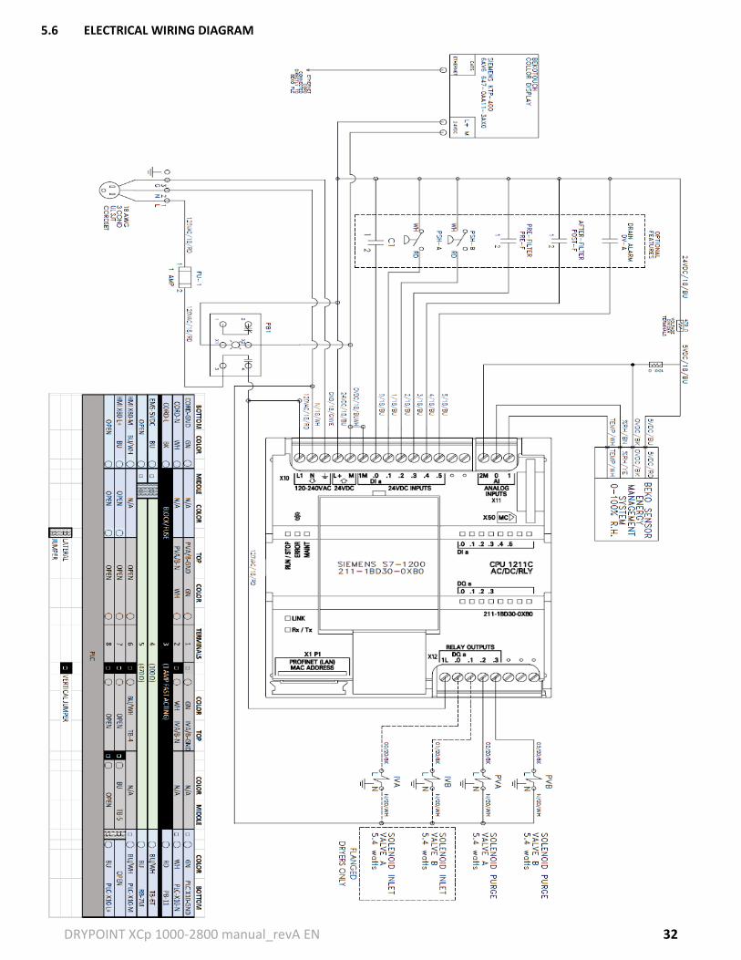
5.6 ELECTRICAL WIRING DIAGRAM
DRYPOINT XCp 1000-2800 manual_revA EN 33
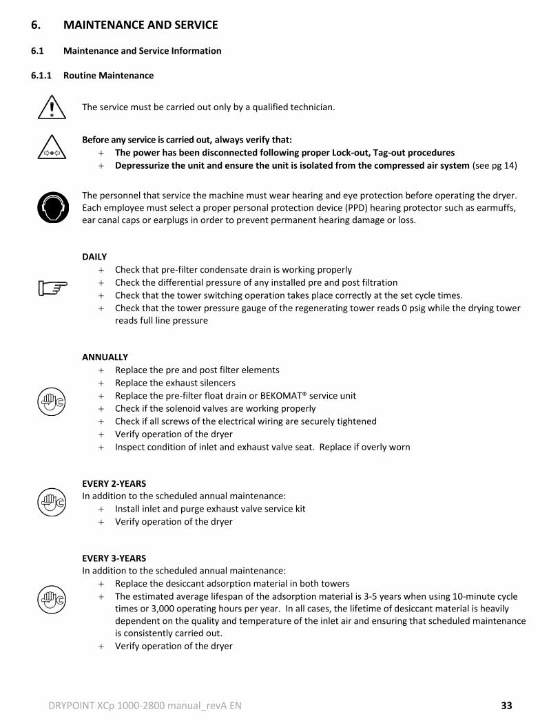
6. MAINTENANCE AND SERVICE 6.1 Maintenance and Service Information 6.1.1 Routine Maintenance
The service must be carried out only by a qualified technician.
Before any service is carried out, always verify that:
The power has been disconnected following proper Lock-out, Tag-out procedures
Depressurize the unit and ensure the unit is isolated from the compressed air system (see pg 14)
The personnel that service the machine must wear hearing and eye protection before operating the dryer. Each employee must select a proper personal protection device (PPD) hearing protector such as earmuffs, ear canal caps or earplugs in order to prevent permanent hearing damage or loss.
DAILY
Check that pre-filter condensate drain is working properly
Check the differential pressure of any installed pre and post filtration
Check that the tower switching operation takes place correctly at the set cycle times.
Check that the tower pressure gauge of the regenerating tower reads 0 psig while the drying tower reads full line pressure
ANNUALLY
Replace the pre and post filter elements
Replace the exhaust silencers
Replace the pre-filter float drain or BEKOMAT® service unit
Check if the solenoid valves are working properly
Check if all screws of the electrical wiring are securely tightened
Verify operation of the dryer
Inspect condition of inlet and exhaust valve seat. Replace if overly worn
EVERY 2-YEARS In addition to the scheduled annual maintenance:
Install inlet and purge exhaust valve service kit
Verify operation of the dryer
EVERY 3-YEARS In addition to the scheduled annual maintenance:
Replace the desiccant adsorption material in both towers
The estimated average lifespan of the adsorption material is 3-5 years when using 10-minute cycle times or 3,000 operating hours per year. In all cases, the lifetime of desiccant material is heavily dependent on the quality and temperature of the inlet air and ensuring that scheduled maintenance is consistently carried out.
Verify operation of the dryer
DRYPOINT XCp 1000-2800 manual_revA EN 34
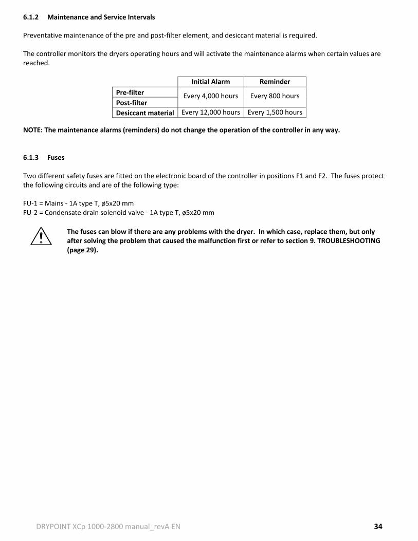
6.1.2 Maintenance and Service Intervals Preventative maintenance of the pre and post-filter element, and desiccant material is required. The controller monitors the dryers operating hours and will activate the maintenance alarms when certain values are reached.
Initial Alarm Reminder
Pre-filter Every 4,000 hours Every 800 hours Post-filter
Desiccant material Every 12,000 hours Every 1,500 hours
NOTE: The maintenance alarms (reminders) do not change the operation of the controller in any way. 6.1.3 Fuses Two different safety fuses are fitted on the electronic board of the controller in positions F1 and F2. The fuses protect the following circuits and are of the following type: FU-1 = Mains - 1A type T, ø5x20 mm FU-2 = Condensate drain solenoid valve - 1A type T, ø5x20 mm
The fuses can blow if there are any problems with the dryer. In which case, replace them, but only after solving the problem that caused the malfunction first or refer to section 9. TROUBLESHOOTING (page 29).
DRYPOINT XCp 1000-2800 manual_revA EN 35
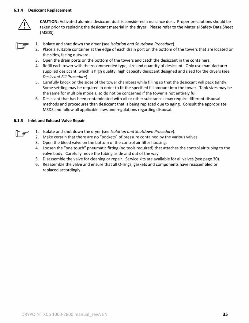
6.1.4 Desiccant Replacement
CAUTION: Activated alumina desiccant dust is considered a nuisance dust. Proper precautions should be taken prior to replacing the desiccant material in the dryer. Please refer to the Material Safety Data Sheet (MSDS).
1. Isolate and shut down the dryer (see Isolation and Shutdown Procedure). 2. Place a suitable container at the edge of each drain port on the bottom of the towers that are located on
the sides, facing outward. 3. Open the drain ports on the bottom of the towers and catch the desiccant in the containers. 4. Refill each tower with the recommended type, size and quantity of desiccant. Only use manufacturer
supplied desiccant, which is high quality, high capacity desiccant designed and sized for the dryers (see Desiccant Fill Procedure).
5. Carefully knock on the sides of the tower chambers while filling so that the desiccant will pack tightly. Some settling may be required in order to fit the specified fill amount into the tower. Tank sizes may be the same for multiple models, so do not be concerned if the tower is not entirely full.
6. Desiccant that has been contaminated with oil or other substances may require different disposal methods and procedures than desiccant that is being replaced due to aging. Consult the appropriate MSDS and follow all applicable laws and regulations regarding disposal.
6.1.5 Inlet and Exhaust Valve Repair
1. Isolate and shut down the dryer (see Isolation and Shutdown Procedure). 2. Make certain that there are no “pockets” of pressure contained by the various valves. 3. Open the bleed valve on the bottom of the control air filter housing. 4. Loosen the “one touch” pneumatic fitting (no tools required) that attaches the control air tubing to the
valve body. Carefully move the tubing aside and out of the way. 5. Disassemble the valve for cleaning or repair. Service kits are available for all valves (see page 30). 6. Reassemble the valve and ensure that all O-rings, gaskets and components have reassembled or
replaced accordingly.
DRYPOINT XCp 1000-2800 manual_revA EN 36
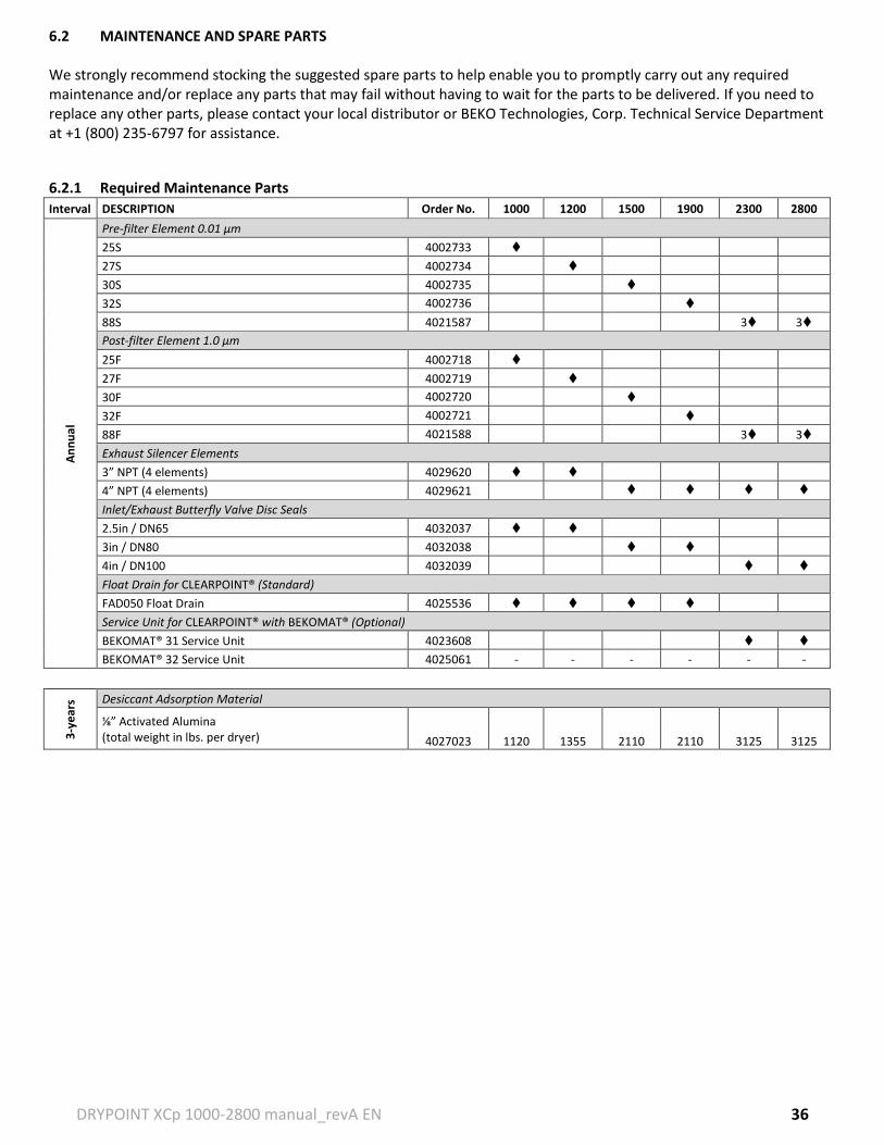
6.2 MAINTENANCE AND SPARE PARTS
We strongly recommend stocking the suggested spare parts to help enable you to promptly carry out any required maintenance and/or replace any parts that may fail without having to wait for the parts to be delivered. If you need to replace any other parts, please contact your local distributor or BEKO Technologies, Corp. Technical Service Department at +1 (800) 235-6797 for assistance.
6.2.1 Required Maintenance Parts
Interval DESCRIPTION Order No. 1000 1200 1500 1900 2300 2800
Service Unit for CLEARPOINT® with BEKOMAT® (Optional)
BEKOMAT® 31 Service Unit 4023608
BEKOMAT® 32 Service Unit 4025061 - - - - - -
3-y
ear
s Desiccant Adsorption Material
⅛” Activated Alumina (total weight in lbs. per dryer) 4027023 1120 1355 2110 2110 3125 3125
DRYPOINT XCp 1000-2800 manual_revA EN 37
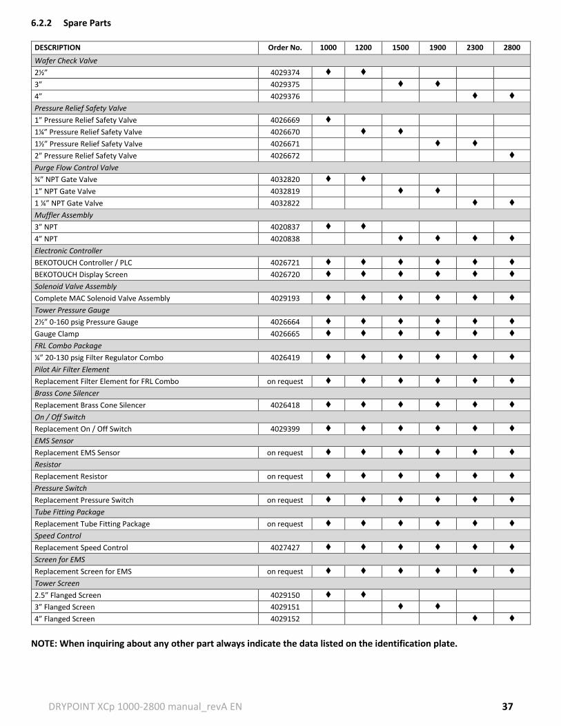
6.2.2 Spare Parts DESCRIPTION Order No. 1000 1200 1500 1900 2300 2800
Wafer Check Valve
2½” 4029374
3” 4029375
4” 4029376
Pressure Relief Safety Valve
1” Pressure Relief Safety Valve
4026669
1¼” Pressure Relief Safety Valve 4026670
1½” Pressure Relief Safety Valve 4026671
2” Pressure Relief Safety Valve 4026672
Purge Flow Control Valve
¾” NPT Gate Valve
1
4032820
1” NPT Gate Valve 4032819
1 ¼” NPT Gate Valve 4032822
Muffler Assembly
3” NPT 4020837
4” NPT 4020838 Electronic Controller
BEKOTOUCH Controller / PLC 4026721
BEKOTOUCH Display Screen 4026720
Solenoid Valve Assembly
Complete MAC Solenoid Valve Assembly 4029193
Tower Pressure Gauge
2½” 0-160 psig Pressure Gauge 4026664
Gauge Clamp 4026665
FRL Combo Package
¼” 20-130 psig Filter Regulator Combo 4026419
Pilot Air Filter Element
Replacement Filter Element for FRL Combo on request
Brass Cone Silencer
Replacement Brass Cone Silencer 4026418
On / Off Switch
Replacement On / Off Switch 4029399
EMS Sensor
Replacement EMS Sensor on request
Resistor
Replacement Resistor on request
Pressure Switch
Replacement Pressure Switch on request
Tube Fitting Package
Replacement Tube Fitting Package on request
Speed Control
Replacement Speed Control 4027427
Screen for EMS
Replacement Screen for EMS on request
Tower Screen
2.5” Flanged Screen 4029150
3” Flanged Screen 4029151
4” Flanged Screen 4029152
NOTE: When inquiring about any other part always indicate the data listed on the identification plate.
DRYPOINT XCp 1000-2800 manual_revA EN 38
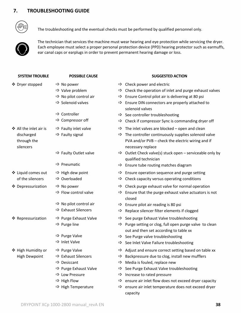
7. TROUBLESHOOTING GUIDE
The troubleshooting and the eventual checks must be performed by qualified personnel only.
The technician that services the machine must wear hearing and eye protection while servicing the dryer. Each employee must select a proper personal protection device (PPD) hearing protector such as earmuffs, ear canal caps or earplugs in order to prevent permanent hearing damage or loss.
SYSTEM TROUBLE POSSIBLE CAUSE SUGGESTED ACTION
Dryer stopped No power
Valve problem
No pilot control air
Solenoid valves
Controller
Compressor off
Check power and electric
Check the operation of inlet and purge exhaust valves
Ensure Control pilot air is delivering at 80 psi
Ensure DIN connectors are properly attached to
solenoid valves
See controller troubleshooting
Check if compressor Sync is commanding dryer off
All the inlet air is
discharged
through the
silencers
Faulty inlet valve
Faulty signal
Faulty Outlet valve
Pneumatic
The inlet valves are blocked – open and clean
The controller continuously supplies solenoid valve
PVA and/or PVB – check the electric wiring and if
necessary replace
Outlet Check valve(s) stuck open – serviceable only by
qualified technician
Ensure tube routing matches diagram
Liquid comes out
of the silencers
High dew point
Overloaded
Ensure operation sequence and purge setting
Check capacity versus operating conditions
Depressurization No power
Flow control valve
No pilot control air
Exhaust Silencers
Check purge exhaust valve for normal operation
Ensure that the purge exhaust valve actuators is not
closed
Ensure pilot air reading is 80 psi
Replace silencer filter elements if clogged
Repressurization Purge Exhaust Valve
Purge line
Purge Valve
Inlet Valve
See purge Exhaust Valve troubleshooting
Purge setting or clog, full open purge valve to clean
out and then set according to table xx
See Purge valve troubleshooting
See Inlet Valve Failure troubleshooting
High Humidity or
High Dewpoint
Purge Valve
Exhaust Silencers
Desiccant
Purge Exhaust Valve
Low Pressure
High Flow
High Temperature
Adjust and ensure correct setting based on table xx
Backpressure due to clog, install new mufflers
Media is fouled, replace new
See Purge Exhaust Valve troubleshooting
Increase to rated pressure
ensure air inlet flow does not exceed dryer capacity
ensure air inlet temperature does not exceed dryer
capacity
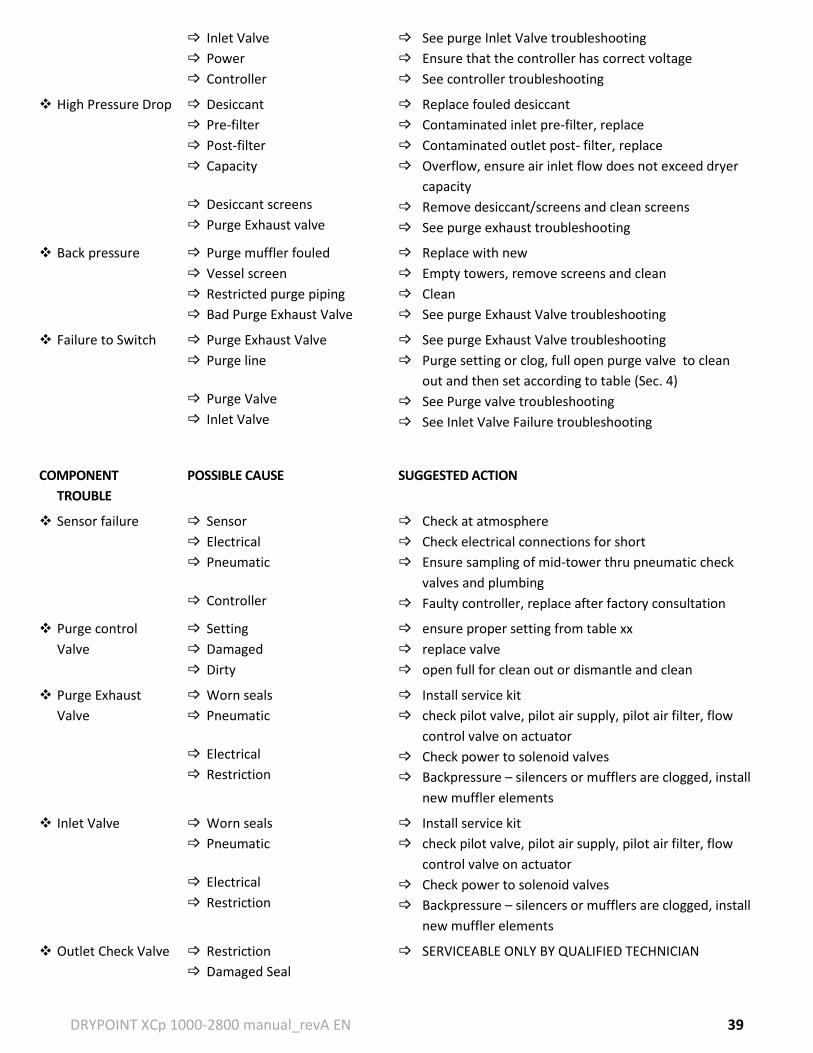
DRYPOINT XCp 1000-2800 manual_revA EN 39
Inlet Valve
Power
Controller
See purge Inlet Valve troubleshooting
Ensure that the controller has correct voltage
See controller troubleshooting
High Pressure Drop Desiccant
Pre-filter
Post-filter
Capacity
Desiccant screens
Purge Exhaust valve
Replace fouled desiccant
Contaminated inlet pre-filter, replace
Contaminated outlet post- filter, replace
Overflow, ensure air inlet flow does not exceed dryer
capacity
Remove desiccant/screens and clean screens
See purge exhaust troubleshooting
Back pressure Purge muffler fouled
Vessel screen
Restricted purge piping
Bad Purge Exhaust Valve
Replace with new
Empty towers, remove screens and clean
Clean
See purge Exhaust Valve troubleshooting
Failure to Switch Purge Exhaust Valve
Purge line
Purge Valve
Inlet Valve
See purge Exhaust Valve troubleshooting
Purge setting or clog, full open purge valve to clean
out and then set according to table (Sec. 4)
See Purge valve troubleshooting
See Inlet Valve Failure troubleshooting
COMPONENT
TROUBLE
POSSIBLE CAUSE SUGGESTED ACTION
Sensor failure Sensor
Electrical
Pneumatic
Controller
Check at atmosphere
Check electrical connections for short
Ensure sampling of mid-tower thru pneumatic check
valves and plumbing
Faulty controller, replace after factory consultation
Purge control
Valve
Setting
Damaged
Dirty
ensure proper setting from table xx
replace valve
open full for clean out or dismantle and clean
Purge Exhaust
Valve
Worn seals
Pneumatic
Electrical
Restriction
Install service kit
check pilot valve, pilot air supply, pilot air filter, flow
control valve on actuator
Check power to solenoid valves
Backpressure – silencers or mufflers are clogged, install
new muffler elements
Inlet Valve Worn seals
Pneumatic
Electrical
Restriction
Install service kit
check pilot valve, pilot air supply, pilot air filter, flow
control valve on actuator
Check power to solenoid valves
Backpressure – silencers or mufflers are clogged, install
new muffler elements
Outlet Check Valve Restriction
Damaged Seal
SERVICEABLE ONLY BY QUALIFIED TECHNICIAN
DRYPOINT XCp 1000-2800 manual_revA EN 40
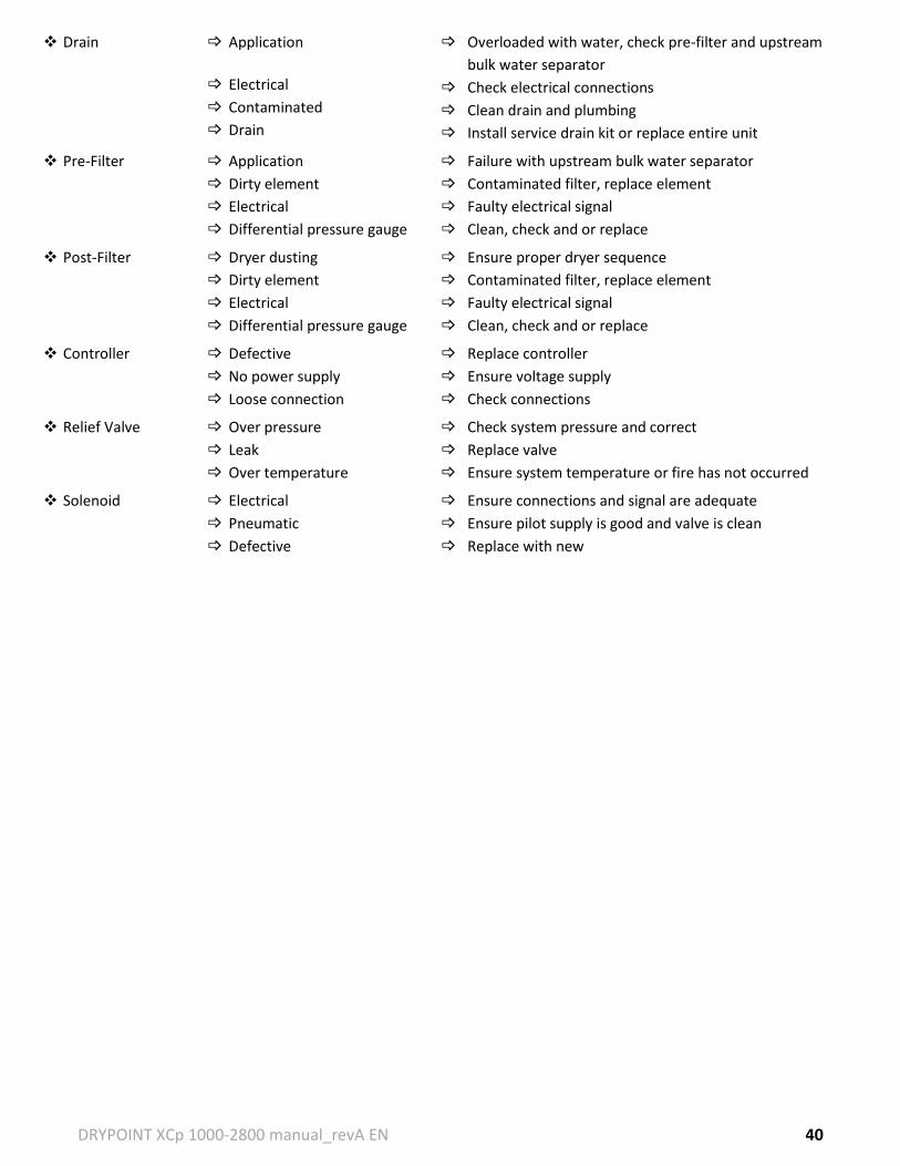
Drain Application
Electrical
Contaminated
Drain
Overloaded with water, check pre-filter and upstream
bulk water separator
Check electrical connections
Clean drain and plumbing
Install service drain kit or replace entire unit
Pre-Filter Application
Dirty element
Electrical
Differential pressure gauge
Failure with upstream bulk water separator
Contaminated filter, replace element
Faulty electrical signal
Clean, check and or replace
Post-Filter Dryer dusting
Dirty element
Electrical
Differential pressure gauge
Ensure proper dryer sequence
Contaminated filter, replace element
Faulty electrical signal
Clean, check and or replace
Controller Defective
No power supply
Loose connection
Replace controller
Ensure voltage supply
Check connections
Relief Valve Over pressure
Leak
Over temperature
Check system pressure and correct
Replace valve
Ensure system temperature or fire has not occurred
Solenoid Electrical
Pneumatic
Defective
Ensure connections and signal are adequate
Ensure pilot supply is good and valve is clean
Replace with new
DRYPOINT XCp 1000-2800 manual_revA EN 41
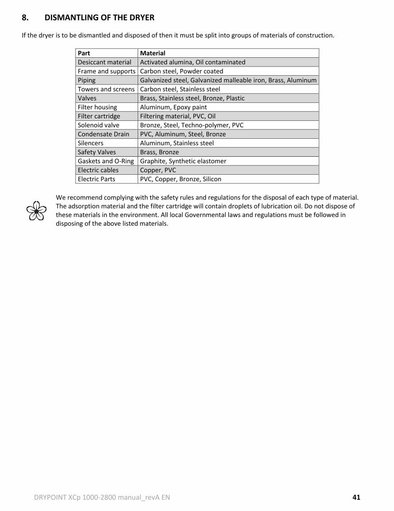
8. DISMANTLING OF THE DRYER
If the dryer is to be dismantled and disposed of then it must be split into groups of materials of construction.
Part Material
Desiccant material Activated alumina, Oil contaminated
We recommend complying with the safety rules and regulations for the disposal of each type of material. The adsorption material and the filter cartridge will contain droplets of lubrication oil. Do not dispose of these materials in the environment. All local Governmental laws and regulations must be followed in disposing of the above listed materials.
DRYPOINT XCp 1000-2800 manual_revA EN 42
9. GENERAL DESCRIPTION OF PARTS
Desiccant – An adsorbent used for drying air or gases. The proper quantity, size and type are necessary.
Inlet Valve – Double acting normally open air operated switching valves used to direct air flow through the towers.
Exhaust Valve – Double acting closed air operated switching valves used to exhaust purge air, hold air in the on-line tower and exhaust air from the tower ready to be regenerated.
Outlet and Check Valves – Valves that allow full flow in one direction and no flow in the opposite direction. These valves are used in conjunction with the inlet and exhaust valves to control the desired flow of process air through the dryer.
Safety Relief Valves – Valves on each tower to protect the vessels from overpressure situations. The setting is indicated on each valve.
Purge Exhaust Silencer – Installed to reduce exhaust noise during purge and blow down for the protection all personnel and to comply with OSHA standards. Silencers are non-mechanical, but must be maintained.
Purge Flow Control Valve – Valve that allows the adjustment and regulation of purge air flow used for the regeneration process.
BEKOTOUCH Controller – Electronic controller that provides an interface between the operator and dryer, provides dryer cycle control, operates the electric solenoid valves, provides indicator lights and alarm controls. All hard wired connections, including the power connections during installation are made to this device.
Electric Solenoid – An electromechanical device used for controlling the flow of liquid or gas.
DRYPOINT XCp 1000-2800 manual_revA EN 43
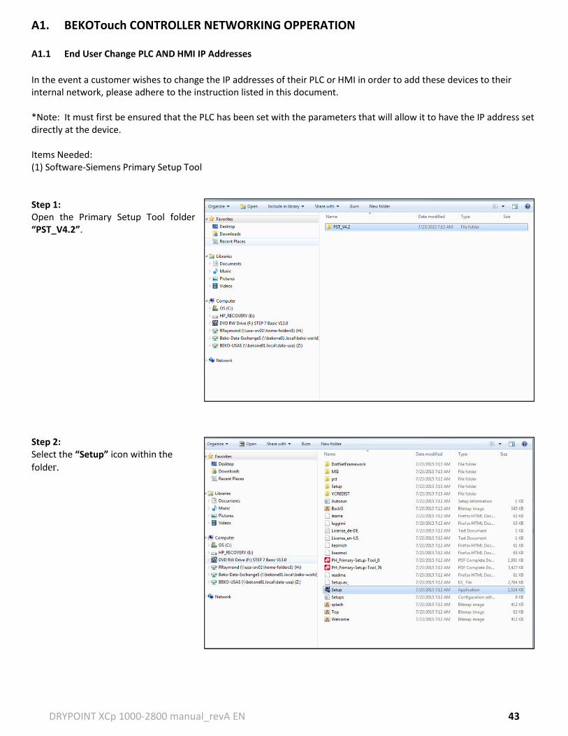
A1. BEKOTouch CONTROLLER NETWORKING OPPERATION
A1.1 End User Change PLC AND HMI IP Addresses
In the event a customer wishes to change the IP addresses of their PLC or HMI in order to add these devices to their internal network, please adhere to the instruction listed in this document. *Note: It must first be ensured that the PLC has been set with the parameters that will allow it to have the IP address set directly at the device. Items Needed: (1) Software-Siemens Primary Setup Tool Step 1: Open the Primary Setup Tool folder “PST_V4.2”. Step 2: Select the “Setup” icon within the
folder.
DRYPOINT XCp 1000-2800 manual_revA EN 44
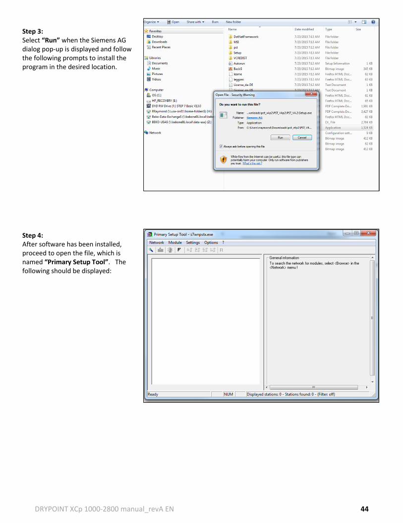
Step 3: Select “Run” when the Siemens AG dialog pop-up is displayed and follow the following prompts to install the program in the desired location. Step 4: After software has been installed, proceed to open the file, which is named “Primary Setup Tool”. The following should be displayed:
DRYPOINT XCp 1000-2800 manual_revA EN 45
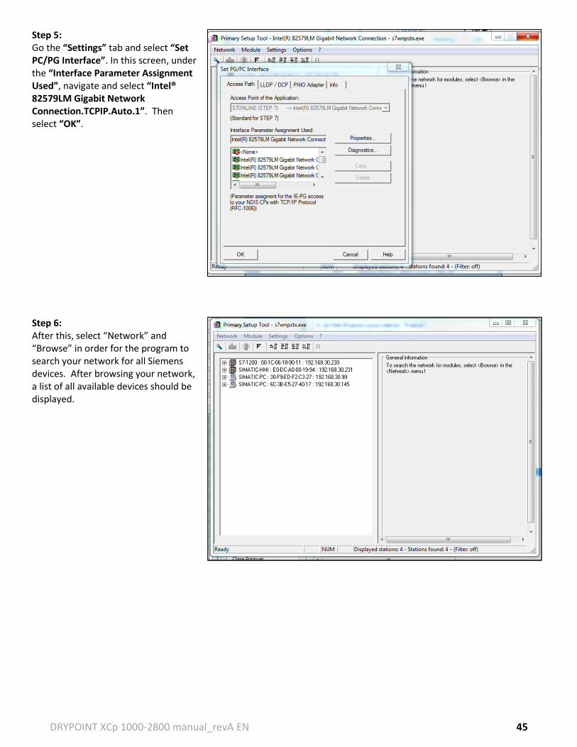
Step 5: Go the “Settings” tab and select “Set PC/PG Interface”. In this screen, under the “Interface Parameter Assignment Used”, navigate and select “Intel® 82579LM Gigabit Network Connection.TCPIP.Auto.1”. Then select “OK”.
Step 6: After this, select “Network” and “Browse” in order for the program to search your network for all Siemens devices. After browsing your network, a list of all available devices should be displayed.
DRYPOINT XCp 1000-2800 manual_revA EN 46
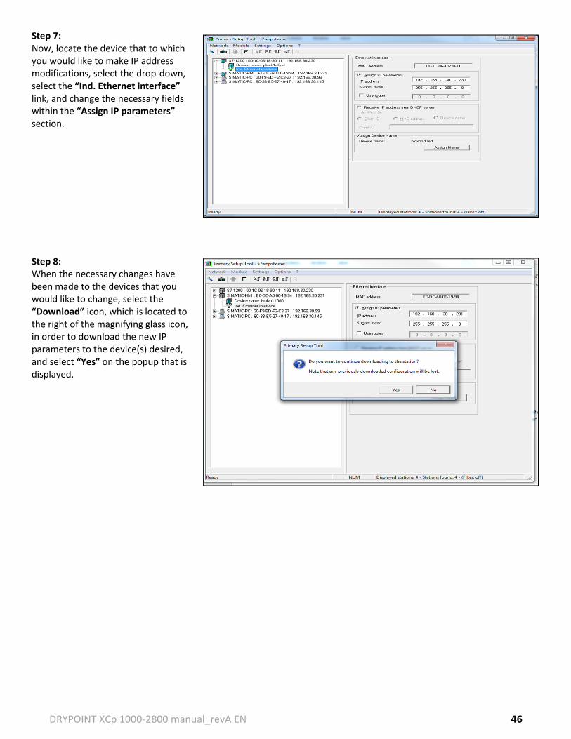
Step 7: Now, locate the device that to which you would like to make IP address modifications, select the drop-down, select the “Ind. Ethernet interface” link, and change the necessary fields within the “Assign IP parameters” section. Step 8: When the necessary changes have been made to the devices that you would like to change, select the “Download” icon, which is located to the right of the magnifying glass icon, in order to download the new IP parameters to the device(s) desired, and select “Yes” on the popup that is displayed.
DRYPOINT XCp 1000-2800 manual_revA EN 47
A1.2 Changing the IP Addess Using ‘Service & Ccommisioning’ (if feature is available in HMI firmware)
In order to start the process of changing the IP address using the ‘Service & Commisioning’, the Control Panel of the HMI must be accessed. The Control Panel can be accessed during HMI startup in which there will be a button displayed allowing the selection of a “Control Panel” pushbutton on the start screen of the HMI. Step 1: Changing PLC IP Address Go to the Control Panel → Select Service & Commissioning → Select IP Adaptation → Next → Accessible devices → Next → Select “Accessible devices in target subnet → Start Scan → Ok → Click “Show” button → Change PLC Address → Select “Assign” button. New PLC IP address should be assigned. Step 2: Changing HMI IP Address Go to the Control Panel → Profinet → IP Address → Select “Specify an IP address” → Type in IP Address & Subnet Mask → Ok. New HMI IP address should be assigned. Step 3: Establishing Communication Between PLC and HMI Go to the Control Panel → Select Service & Commissioning → IP Adaptation → Next → Select “Override project connection information → Next → Select “Edit Connection” button → Type in IP address of PLC that will be connected to the HMI & Select “Override connection parameter” checkbox → Select “Apply” button. After all of these steps have been followed, select the “X” button at the top of the menus to go back to the HMI root menu and select “Start” in order to go to the dryer’s HMI start screen. If connection is successfully established, the program should continue running and the home screen displaying the current step in the dryer process.
DRYPOINT XCp 1000-2800 manual_revA EN 48
A1.3 DRYPOINT XCp Webserver (Standard)
A1.3.1 Accessing the data logging feature on the DRYPOINT XCp.
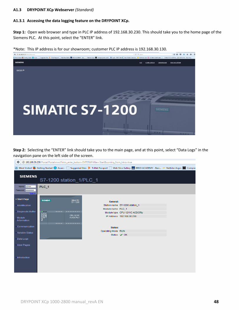
Step 1: Open web browser and type in PLC IP address of 192.168.30.230. This should take you to the home page of the
Siemens PLC. At this point, select the “ENTER” link.
*Note: This IP address is for our showroom; customer PLC IP address is 192.168.30.130.
Step 2: Selecting the “ENTER” link should take you to the main page, and at this point, select “Data Logs” in the
navigation pane on the left side of the screen.
DRYPOINT XCp 1000-2800 manual_revA EN 49
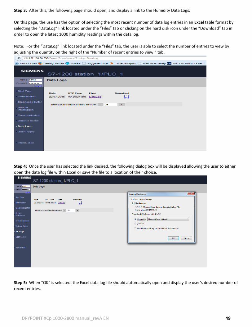
Step 3: After this, the following page should open, and display a link to the Humidity Data Logs.
On this page, the use has the option of selecting the most recent number of data log entries in an Excel table format by
selecting the “DataLog” link located under the “Files” tab or clicking on the hard disk icon under the “Download” tab in
order to open the latest 1000 humidity readings within the data log.
Note: For the “DataLog” link located under the “Files” tab, the user is able to select the number of entries to view by
adjusting the quantity on the right of the “Number of recent entries to view:” tab.
Step 4: Once the user has selected the link desired, the following dialog box will be displayed allowing the user to either
open the data log file within Excel or save the file to a location of their choice.
Step 5: When “OK” is selected, the Excel data log file should automatically open and display the user’s desired number of
recent entries.
DRYPOINT XCp 1000-2800 manual_revA EN 50
A1.3.2 Guide to Navigating the Webserver After the user has typed in the necessary IP address to the PLC and has established successful communication with the PLC, the following page will be displayed, and the user will select the Enter link.
Once the Enter link has been selected, the Start Page will be displayed and displays General PLC information as well as current PLC status.
Identification: allows access to the PLC hardware and firmware information.
DRYPOINT XCp 1000-2800 manual_revA EN 51
Diagnostic Buffer: allows access to the diagnostic information related to the PLC in terms of starting and stopping and power on or off.
Module Information: allows access to the PLC Station and its status.
S7-1200 Station 1: displays the PLCs currently active within the network.
DRYPOINT XCp 1000-2800 manual_revA EN 52
PLC 1: displays the occupied slots within the PLC in terms addresses as well as any other IO cards attached to the PLC.
Communication link: allows access to the display of PLC communication parameters and statistics.
Variable Status link (if the option has been enabled): allows access to PLC system addresses for the monitor of specified variables.
DRYPOINT XCp 1000-2800 manual_revA EN 53
Data Logs: allows access to the Humidity Data Log.
User Pages (if the option has been purchased): allows access to the custom Beko Webpage which allows for remote monitoring of the unit.
DRYPOINT XCp 1000-2800 manual_revA EN 54
A1.4 DRYPOINT XCp Custom Webpage (Optional) Accessing the BEKO configured user webpage feature on the DRYPOINT XCp.
Step 1: Open web browser and type in PLC IP address of 192.168.30.230. This should take you to the home page of the
Siemens PLC. At this point, select the “ENTER” link.
*Note: This IP address is for our showroom; customer PLC IP address is 192.168.30.130.
Step 2: Selecting the “ENTER” link should take you to the main page, and at this point, select “User Pages” in the
navigation pane on the left side of the screen.
DRYPOINT XCp 1000-2800 manual_revA EN 55
Step 3: After this, the following page should open, and display a link to the
“Homepage of the Application Beko Dryer Webpage”.
Step 4: Once the user has clicked the “Homepage of the application Beko Dryer Webpage” link, the following page will
be displayed. This main page is the System Status page and displays the current state of the dryer. There are also three
other pages that the user can access which are located on the navigation pane on the left side of this screen. (We are also
working on adding a generic picture for the main page displaying the tower graphics).
DRYPOINT XCp 1000-2800 manual_revA EN 56
Step 5: When the user selects the “SETTINGS” link the below page should be displayed, allowing the user to remotely
modify the time and date on the PLC and HMI.
Step 6: When the user selects the “ALARMS” link the below page should be displayed, allowing the user to view the last
10 alarms generated by the PLC.
DRYPOINT XCp 1000-2800 manual_revA EN 57
Step 7: When the user selects the “SPARE PARTS LIST” link the below page should be displayed, allowing the user to view
the spare parts list for that particular dryer unit.
DRYPOINT XCp 1000-2800 manual_revA EN 58
For technical product support please call +1 (800) 235-6797 and select Option 2