Good servicing requires extensive and relevant training as well as comprehensible referencedocuments.
We therefore offer basic and advanced training courses for the full range of our products to allservice technicians on a regular basis.
In addition, we produce service manuals for the major units in our product line. While these areideal for initial use as instruction manuals, they are designed to serve as an essential referencein the future.
To augment our product-related communications, we regularly distribute service informationbulletins providing details about ongoing product development.
Copyright Notice
Copyright 2002 by Alfred Kärcher GmbH & Co. All rights reserved. No part of this publication maybe reproduced, stored in a retrieval system, or transmitted in any form or by any means, i.e.,electronic, mechanical, photocopying, recording or otherwise, without the written permission ofAlfred Kärcher GmbH & Co.
ALFRED KÄRCHER GmbH & Co.Customer Service TrainingP.O. Box16071349 Winnenden, Germany
http://www.karcher.de
3
KMR 1250 B, LPG, D Table of Contents
Contents
Unit functions ...........................................................................................................4-15Overview ............................................................................................................................... 4-5
View from front ..........................................................................................................................6
LP Gas Engine (HONDA GX 270) ....................................................................................... 10-11
Diesel Engine (YANMAR L 70 AE-DE) ............................................................................... 12-13
Steering and Drive Power ........................................................................................................14
Sweeping system ....................................................................................................................15
Troubleshooting Information ................................................................................... 4-15Starter Fails to Turn Engine ............................................................................................... 16-18
Starter Turns Engine but Engine Fails to Start ................................................................... 19-20
Engine Runs but Machine Fails to Move ............................................................................ 21-25
Maintenance Procedures (gasoline and LPG engine) ....................................................... 26-27
Brush Roller – No Rotation ......................................................................................................35
Side Brushes – Poor Sweeping Performance .........................................................................36
Excessive Unit Dusting...................................................................................................... 37-41Filter cleaning Motor – No Function .........................................................................................42
Hydraulic Unit – No Function ................................................................................................... 43
Debris Container – Very Slow Ascent ......................................................................................44
Debris Container – No Full Ascent ...........................................................................................45
Excessive Steering Free Play ..................................................................................................46
Engine 1250 LPGWith the exception of the conversion to run onliquefied petroleum gas (LPG), the unit is iden-tical to the basic KMR 1250 B version.
– The gasoline engine is the same as in the KMR1250 B (HONDA GX 270).
– The LP gas cylinder is mounted behind thedriver’s seat. As the gasoline tank is discon-nected, its use is strictly prohibited.
– The carburetor has been converted to LP gasoperation.
– The engine compartment accommodates anadditional gas regulator required to adjust theair/fuel mixture for the engine.
– The mechanical choke has been converted toelectrical control; it acts upon the gas regula-tor.
Engine 1250 DWith the exception of the different engine type,the unit is identical to the basic KMR 1250 Bversion.
– Single-cylinder, air-cooled diesel engine (YAN-MAR L 70 AE-DE) w/ electric starter.
– Features compression release for short-termoperation to help overcome top dead centerwhen starting the engine.
6
Unit Functions KMR 1250 B, LPG, D
View from front
1 Gas cylinder (LP Gas)2 Steering wheel3 Driver seat4 Lifting mechanism for debris container5 Rear wheel, chain-driven6 Fuel tank for KMR B / D7 Engine KMR B / LPG / D8 LH side brush (option)9 Front wheel10 Head lights11 RH side brush12 Controls (see page 7)
KARCHER
KMR
25
0
1
KARCHER
KMR
25
01
5
21 3 4
78911 1012 6
7
KMR 1250 B, LPG, D Unit Functions
1 Lever dust pickup, Close / Open2 Button clean dust filter (S2)3 Button lower debris container (S6)*4 Button raise debris container (S8)*5 Button tilt debris container (S7)*6 Lever parking brake7 Lever coarse-dirt flap8 Headlight switch (S4)9 Operating hours counter10 Button two-hand operation, hydraulic (S5)11 Lever LH side brush, Raise / Lower
(option)
12 Lever brush roller, Raise / Lower(suspension: rigid or floating)
13 Lever RH side brush, Raise / Lower14 Throttle lever15 Button horn (S10)16 Ignition switch (S1)17 Choke18 Drive pedal ORIGINAL and REVISED
* Function available only in conjunctionwith two-hand operation button (10).
( ) See circuit diagram.
Controls
11 12 13 14 16 17 16
10
9
8
7
6
5
4
3
2
1
15
14
15
1818
16
15
14
17
8
Unit Functions KMR 1250 B
Gasoline Engine (HONDA GX 270)
1 Stop screw, throttle valve2 Idle jet3 Bypass4 Throttle valve5 Idle orifice6 Idle jet bore and idle air channel7 Carburetor throat (venturi)8 Idle air inlet9 Choke valve10 Main air jet11 Idle system
Float systemWhen float chamber (14) is empty, fuel passesfrom fuel tank into float chamber (14) via the floatvalve inlet (18). The rising fuel level causes thefloat (21) to be raised.The inflow of fuel is interrupted when the float(21) causes the float valve to close. Drawing fuelfor engine operation from the float chamber (14)causes the float (21) to be lowered, which in turnopens the float valve (18).This cyclical procedure ensures a constant levelof fuel inside the float chamber (14).
Float chamber equalizationOn the carburetor side, the airspace inside thefloat housing is connected with the outside at-mosphere by means of a channel. This facili-tates the equalization of the pressure equilibri-um inside the float chamber as the fuel level ris-es or falls.
Idling operationWhen the engine is idling, the throttle valve (4) isfully closed.– This causes negative pressure to occur be-
tween the throttle (4) and the crown of theengine piston, with the latter moving towardbottom dead center while the intake valve isopen.
– The atmospheric pressure inside the floatchamber (14) then causes fuel to be con-veyed through the main jet (15) and idle jet(2).
– The idle jet (2) controls the flow of fuel throughthe idle bypass channel (3). The fuel thenblends with the air being drawn in throughthe idle air channel (6).
– The resulting air/fuel mixture then flows intothe engine.
– The idle mixture adjusting screw (16) con-trols the volume of air/fuel mixture that is al-lowed to flow through the idle orifice (5).
Partial load operationEngine speed rises when the throttle valve (4)opens, and the volume of the air/fuel mixturebeing drawn through the idle jet (2) increases.
Full load operationIn full load operation, the throttle is wide (4) open:– Air flows through the carburetor throat, or
venturi (7). Because the diameter of the ven-turi outlet is smaller than that of the intake,the air is accelerated as it passes through.This increased flow velocity causes nega-tive pressure to occur at the outlet side of themain jet (15).
– Pressure inside the float chamber (14) isequalized via an atmospheric relief channel.Because atmospheric pressure is higher thanthe pressure in the carburetor throat (7), fuelis transported from the float chamber (14),and pressed through the main jet (15) intothe emulsion tube (12).
– The air flowing through the main air jet (10)is blended with the fuel that is flowing throughthe orifices of the emulsion tube (12).
– This mixture is then drawn into the carbure-tor throat (7), where it is enriched with moreair before passing into the engine.
Choke system functionThe choke valve (9) should be closed only whenstarting a cold engine. This causes the followingto happen:– The closed choke valve (9) allows less air to
be drawn into the carburetor throat (7).– However, the fuel volume being drawn in
through the main jet (15) remains the same.– This causes the fuel component in the air/
fuel mixture to rise, with the richer mixtureproviding easier engine starting.
Note:For information on other maintenance andadjustments of the engine, refer to the Serv-ice manual „4-Stroke Internal CombustionEngines“ (5.905-122).
10
Unit Functions KMR 1250 B, LPG, D
1 Valve guard2 LP gas line3 Cylinder shutoff valve4 Outlet tube5 LP gas cylinder6 Sun shield7 LP gas in gaseous state8 LP gas in liquid state9 Carburetor
10 Engine11 Vacuum line12 LP gas line13 Gas filter14 Solenoid valve, gas supply15 Mixture control screw (MIN eng. speed)16 Gas regulator17 Choke lifting solenoid18 Mixture control screw (MAX eng. speed)
LP Gas Engine (HONDA GX 270)
11
14
8
17
16
18
9
10
7
654
2
1
3
15 1314 12 11 12
1615
18
13
11
KMR 1250 B, LPG, D Unit Functions
– The presence of frost on any part of the LP gassystem indicates a possible leak. Close thecylinder shutoff valve (3) immediately. Applysuitable leak detection medium (soapy wateror Leak Detecting Spray 6.282-033) to gaslines, solenoid valve, gas regulator and gashose to carburetor. Open cylinder shutoff valve(3), and check for formation of bubbles. Theunit may be returned to service only after thor-ough repairs have been carried out by ap-proved specialists.
Note:The LP gas system of the unit must be in-spected by a licensed expert in 6-monthintervals. The results of each inspection mustbe made available in the form of a test cer-tificate.
– An expert is deemed to be a person who, basedon his professional education and skills, pos-sesses sufficient knowledge of, and expertisein, the field of LP gas systems, and who issufficiently familiar with applicable workingdirectives and accident prevention regulations,as well as commonly accepted procedures ofthis technology, all of the above enabling himto evaluate, determine and assess the safeoperational state of LP gas systems.
Gas system
– Opening the shutoff valve (3) on the LP gascylinder (5) causes gas to flow through the gasfilter (13). At this point, possible contaminantsare trapped in a paper filter, and metallic par-ticles from gas cylinder are removed by meansof a small magnet.
– Setting ignition key to Pos. 1 (ON) opens so-lenoid valve (14), allowing LP gas to flow fromgas filter (13) into primary chamber of gas reg-ulator (16). Here, a spring-loaded valve reduc-es gas pressure to approximately 150 mbar(2.2 psi).
– When starter begins to crank engine (10), avacuum is created in the suction channel.Through vacuum line (11), this vacuum actson low-pressure diaphragm in secondary stageof gas regulator. Diaphragm opens low-pres-sure valve, and gas can be drawn into engine.
– Pressing choke button causes choke liftingsolenoid (17) to open low-pressure valve, al-lowing gas to flow directly through carburetorand into engine. This function is particularlyimportant in cold-starting situations. To pre-vent high-level enrichment of intake mixturewith LP gas, choke button should not bepressed for longer than 3-5 seconds.
Note:The connection on cylinder shutoff valve (3)must face straight up (extraction of LP gasin gaseous state).
LP Gas Engine (HONDA GX 270)
Carburetor in LP gas operation (example)
1 Gas inlet2 Air intake3 Air/fuel mixture outlet4 Mixing chamber5 Gas jet
Gas regulator
– Engines using LP gas as a fuel are equippedwith a gas regulator which feeds LP gas to thecarburetor of a gasoline engine. The carbure-tor generates an air/fuel mixture which is drawninto the combustion chamber for ignition.
Note:For information on other maintanance andadjustments of the engine, refer to the Serv-ice manual “4-Stroke Internal CombustionEngines” (5.905-122).
Injection systemThe injection pump (8) delivers fuel to the injec-tor nozzle (5) via fuel line (6). The fuel, is theninjected into the combustion chamber above theengine piston (3), where the extreme enginecompression causes the fuel to self-ignite.
Note:For information on other maintenance andadjustments of the engine, refer to the Serv-ice manual „4-Stroke Internal CombustionEngines“ (5.905-122).
6
1
2
3
4
5
7
8
11
10
9
13
KMR 1250 B, LPG, D Unit Functions
Diesel Engine (YANMAR L 70 AE-DE)
Injection pump (cross-section)
Injection pumpThe injection cam on the camshaft shuttles theinjection pump piston (1) back and forth. Fuel isconveyed to the injection nozzle via pressurevalve (7).Injection timing is determined by the thicknessand number of shims (2) in shim pack.
Note:Checking injection timing and related fineadjustment are the exclusive domain of alicensed service facility.
In the event that the injection pump fails to deliv-er fuel, the entire injection pump assembly mustbe removed and checked.
Note:Injection pump service and repair are theexclusive domain of a licensed service facil-ity.
Injector assemblyThe fuel that is conveyed to the injector by theinjection pump is transported through the feedchannel (14), past the nozzle valve (13), and thensprayed into the engine combustion chamber.
8 Rear wheel9 Debris container, lowered10 Hydrostatic transmission11 Brush roller12 Coarse-dirt flap13 Front wheel14 Side brush
4
2
1
14 13 12 11 10 9 8
6
7
5
3
16
Troubleshooting Information KMR 1250 B, LPG, D
Check fuse F1/F2Fuse F2 protects the entire control voltage cir-cuitry. This fuse is located on the A1 circuit board.– Check fuse and replace as required.
A1 Circuit boardF1 Fuse, motor filter cleaning (10 A)F2 Fuse, control voltage (7,5 A)
Check battery voltage– Check battery voltage with voltmeter.– Check electrolyte level on low-maintenance
battery.– If required, recharge battery using external
battery charger (e.g., P/N 6.654-046).
Fuses F1/F2 on A1 circuit board
Fuse F4 in electrical box
Checking ignition switch S1 while removed from unit
Check fuse F4 and wiringWhen the engine is running, the battery receivesa steady charge current from the alternator.The fuse F4 (15 A rating) protects this circuit.The fuse is located beneath the electrical box.– Check fuse and replace as required.– Check all wiring and connections between
alternator and battery.
Check ignition switch S1– Remove screws on instrument panel (2), and
carefully lift off instrument panel.– Check ignition switch (1) for continuity at its
various positions (0, 1, 2).
Key position Connection Function0 30/1 - 15 Engine Stop1 30 - 15/54 In operation2 30 - 50 Starter
Check voltage on starter solenoid– Hold ignition switch in position II.– Measure the voltage between solenoid ter-
minal and vehicle ground.– If the meter fails to indicate a voltage, wiring
must be checked for possible defect.– If a voltage is present but starter fails to turn,
starter is defective and must be replaced.
Note:The connecting wiring for the starter sole-noid are not shown in electrical diagram.
Checking voltage on starter motor M1
Checking voltage on starter solenoid
Check starter M1– Hold ignition switch in position II.– If a voltage is present but starter fails to turn,
starter is defective and must be replaced.
Starter Fails to Turn Engine
V
SW
V
18
Troubleshooting Information KMR 1250 B, LPG, D
Check regulator ORIGINAL
When the engine is running, the alternator gener-ates a continuous current flow. The regulatorautomatically adapts this current as required(depending on battery charge status and electri-cal load).– Start engine and allow to run.– Using a clip-on ammeter, measure regulator
charging current on X1 plug coupling (whitewire on male connector or red wire on femalecoupling of X1 connector).
If a charging current cannot be measured, thisindicates that the alternator is faulty and must bereplaced.
Checking regulator charging current
Starter Fails to Turn Engine
Checking regulator charging current
Check regulator REVISED
Units of recent manufacture no longer featurethe X1 plug coupling. Wires are connected byindividual round plug couplings instead.– Start engine and allow to run.– Using a clip-on ammeter, measure regulator
charging current on red-and-white wire cou-pling.
If a charging current cannot be measured, thisindicates that the alternator is faulty and must bereplaced.
ws White wirert Red wire1 Plug coupling2 Round male plug w/ female coupling
ws
rt
A
A
1
ws
rtA
A 2
19
KMR 1250 B, LPG, D Troubleshooting Information
Checking S3 seat contact switch
Note:Actuating the starter without a load on theseat will crank the engine but not start it!
– Disconnect wire connections from seat con-tact switch.
– Connect an ohmmeter to check seat contactswitch for continuity.
– With a physical load on the seat cushion, theswitch opens, and there is no continuity.
– In the absence of a physical load on the seatcushion, switch contacts are closed.
– Adjust or replace seat contact switch as re-quired.
Checking spark plug (gasoline & LPG engine)
Checking seat contact switch S3
Check spark plug(gasoline and LPG engine)– If ceramic insulator shows signs of break-
age of cracking, spark plug must be replaced.– Heavily fouled spark plugs must be replaced.– Using a feeler gauge, measure electrode gap,
and bend electrodes to adjust as required.– To compress captive seal washer on new
spark plug, screw in plug hand-tight, thentighten 1/2 turn. Tighten used spark plugsonly by 1/8 to 1/4 turn.
Check oil level switch S9(gasoline and LPG engine)In the event that the engine oil level drops downtoo far, the oil level switch cuts out the ignition.This causes the engine to stall and will preventengine restarts.– Remove the terminal of the yellow wire.– Using the ohmmeter, check the connecting
terminal for continuity.– If the oil level is sufficiently high, there will be
no continuity.– If the oil level is too low, there must be con-
tinuity.– Top up engine oil or replace oil level switch
Check compression release lever (dieselengine)– Engine is equipped with compression release
lever. During engine starting, it can be actu-ated for a short while to ease overcomingengine resistance at top dead center.
Note:To enable engine to start with hood open,seat contact switch must be jumpered.Jumper must again be removed once en-gine has started.
Fuel filter (diesel engine only)
Compression release lever (diesel engine)
4 2
1
3
5
6
7
Using Diesel fuel (diesel engine)Exceptionally low outdoor temperatures maycause diesel fuel to congeal. In this condition,fuel is no longer supplied to the engine.– To prevent this condition occurring, add vis-
cosity agents (winterized diesel fuel or dena-tured alcohol) to the tank before cold weath-er sets in.
– If the fuel congeals, replace fuel tank contentwith winterized diesel fuel or add viscosityagents.
– Continue by allowing the power sweeper towarm up in a cold environment, with engineidling.
1 Oil filler neck2 Lever, compression release3 Injector line4 Injector5 Tank filler cap6 Seal ring7 Fuel filter
21
KMR 1250 B, LPG, D Troubleshooting Information
Check freewheeling functionThe transmission features a freewheeling leverwhich can be used to engage or disengage thedrive power.Starting with S/N 10121, this freewheeling leveris permanently mounted on the transmission link-age. It is held in place in the engaged position bya stop bracket.Even with the drive engaged, the unit may beslowly pushed by hand. However, the drive mustbe disengaged (clockwise rotation) if the unit isto be moved over extended distances.– Position 1: Transmission engaged– Position 2: Transmission disengaged
Note:It is important to prevent inadvertent disen-gagement of the freewheeling lever. Other-wise, no drive power can be applied, andengine braking will be ineffective.
Freewheeling lever on transmission
Engine Runs but Machine Fails to Move
Transmission drive beltThe transmission drive belt tension is adjustedby means of the tension roller. The drive beltmust be sufficiently tight so that it will not wowthrough more than 3 to 8 mm (0.12-0.32 in) whenapplying a force of 2 kg ( 20 N) to the center of thelongest span.Replace drive belt as required, ensuring that ten-sion roller has first been relaxed.
Transmission drive belt with tension roller
1 2ON OFF
22
Troubleshooting Information KMR 1250 B, LPG, D
Checking drive pedal ORIGINAL
A linkage connects the drive pedal to the shiftlever (2) on the transmission (7). When the drivepedal is not actuated, the shaft-mounted legspring (6) always returns this lever to the centerposition .When at the center position, the drive pedal ad-justment should provide for equal angles fromthe horizontal for both forward and return foot-rests.An adjusting screw (8) beneath the drive pedallimits pedal travel and, at the same time, the max.drive speed (see technical specifications).
Note:This limit must be observed especially in thecase of units licensed for road travel.
It is essential that the shaft-mounted leg spring(6) securely rests against the dog pin (4) andstop pin (5), and that it does not slip past thesetwo limiters (check intermediate plate (3)).With the drive pedal at center position and withthe parking brake released, the unit may moveneither forward nor backward.The drive pedal must travel without jerking orbinding.
Note:All adjusting screws must be fixed with seal-ing lacquer.
Adjusting drive pedal
Shift lever on transmission
Engine Runs but Machine Fails to Move
1 Drive pedal linkage2 Shift lever3 Intermediate plate4 Dog pin in shift lever5 Stop pin in transmission6 Shaft-mounted leg spring7 Transmission8 Adjusting screw
8
23
KMR 1250 B, LPG, D Troubleshooting Information
Engine Runs but Machine Fails to Move
Shift lever on transmission
Adjusting drive pedals
Checking drive pedal REVISED
A linkage connects the drive pedals to the shiftlever (4) on the transmission (1). When the drivepedals are not actuated, the pull spring (3) al-ways returns this lever to the center position.When at the center position, the drive pedalsshould be adjusted so that the forward and re-verse pedals at equal angles from the horizontal.Two adjusting screws (5 and 6) beneath the drivepedals limit pedal travel and, at the same time,determine the max. drive speed (see technicalspecifications).
Note:These limits must be observed especially inthe case of units licensed for road travel.
With the drive pedals at center position and withthe parking brake released, the unit may moveneither forward nor backward.The drive pedal must travel without jerking orbinding.
Note:All adjusting screws must be fixed with seal-ing lacquer.
Adjust hydrostatic transmissionStarting with serial no. 11482 to serial no. 11882,the hydrostatic transmission (1) is installed in aslanted position. As the slant is not adjustable,engine and transmission drive belts may fail aftera short while.Starting with serial no. 11883, it is possible toadjust the incline of the hydrostatic transmission.To this end, the holding bracket (3) was providedwith an elongated hole.– Loosen adjusting bolt (2).– Position hydrostatic transmission so that drive
belts run straight in belt pulleys.– Securely tighten adjusting bolt and seal with
safety paint (2).
Note:Retrofitting kit 2.882-530 is available for unitswith serial no’s. 11482 through 11883. (Re-
Clean air filter elementWhen filter element is dirty, replace the paperfilter element (2). To clean filter element, blowthrough with compressed air from the inside out,or firmly tap on hard surface to dislodge caked-on dust. Do not brush off because this wouldpress dust particles into paper fibers.Wash foam ring (2) with a mild solution of house-hold detergent. Rinse thoroughly and allow to dry.Immerse foam insert in clean engine oil, andsqueeze to remove excess oil. If too much oil isallowed to remain in foam insert the engine willsmoke while running.
Oil dipstick
Draining engine oil
Air cleaner w/ foam insert and paper element
Maintenance Procedures (gasoline and LPG engine)
1 Foam ring2 Paper element
1
2
27
KMR 1250 B, LPG, D Troubleshooting Information
Carburetor w/ fuel cock and sediment bowl
Operating RPM adjustmentThe engine operating speed (refer to „Specifica-tions“) is set by means of the adjustment screw(1). Once the setting is correct, the screw mustbe fixed with sealing lacquer.
Adjusting engine operating speed
Maintenance Procedures (gasoline and LPG engine)
Clean sediment bowl– Set fuel cock (2) to OFF position.– Remove sedimentation cup (3) complete with
O-ring, and wash out with nonflammablecleaner or inert cleaning solvent. Allow to drythoroughly, then install and tighten securely.
– Set fuel cock (2) again to OPEN position.Check for possible leaks around sedimenta-tion cup.
Note:Ensure that no spilled fuel remains in areaaround carburetor before starting engine.When engine has started, check sedimen-tation cup for leaks.
1 Adjusting screw, engine operating RPM2 Fuel cock3 Sedimentation cup
1
2
3
28
Troubleshooting Information KMR 1250 LPG
Maintenance Procedures (LPG engine)
Set CO value (LPG engine)To adjust CO value, the following measuring de-vices will be needed:– Tachometer, P/N 6.491-361– Exhaust analyser. Procure suitable CO an-
alyser locally; requires measuring range upto 2% CO.
Removing muffler guard
Setting CO value w/ mixture control screw (idlespeed)
Measuring CO value inside muffler tailpipe
1. Set CO value at idle speed– Start engine, and set accelerator lever on
instrument panel to MIN position. Idle speedshould be between 1250 and 1550 RPM (seealso “technical specifications”).
– Let engine warm up for a few minutes.– Using a floor jack, raise front of unit, and
remove muffler guard (1). There is no otherway to access the muffler outlet.
– Measure CO value inside muffler tailpipe (2).– Using the mixture control screw idle speed)
(5), set CO value on gas regulator (4) (nom-inal CO value is 0.5% ).
– With the correct adjustment, engine must runsmoothly and quietly, and provide reliablestarting.
– With adjustment completed, fix mixture con-trol screw (5) by applying sealing lacquer.
1 Muffler guard2 Muffler3 Solenoid valve
4 Gas regulator5 Mixture control screw (idle speed)
1
2
3
4
5
29
KMR 1250 LPG Troubleshooting Information
Maintenance Procedures (LPG engine)
2. Set CO value at operating speed– Set accelerator lever on instrument panel to
MAX position (operating speed).– Measure operating RPM and adjust via stop
screw (6) on carburetor as required. Operat-ing speed has to be between 2600 and 2700RPM (see also “technical specifications”).
– With adjustment completed, fix carburetorstop screw (6) by applying sealing lacquer.
– Check CO value inside muffler tailpipe.
Adjusting operating speed
Setting CO value w/ mixture stop screw (oper.speed)
– Using the mixture control screw (idle speed)(7) (operating speed), set CO value on gasregulator (4) (nominal CO value is 0.5%) .
– With the correct adjustment, engine must runsmoothly and quietly, and provide reliablestarting.
– With adjustment completed, fix mixture con-trol screw (7) by applying sealing lacquer.
3 Solenoid valve4 Gas regulator5 Mixture control screw (idle speed)6 Carburetor stop screw7 Mixture control screw (operating speed)
6
7
3
4
5
30
Störungshilfe KMR 1250 D
Note:For operating and maintenance instructions,consult the Operator Manual for this engine.
Check engine oil level– Engine oil level must be between the MIN and
MAX markings on the dipstick.
Top up engine oil– The dipstick hole is used to add new oil to the
engine. For oil type and required volume, referto “Specifications”.
Change engine oil– Place a suitable catch tray beside the unit.– While holding oil drain hose in catch tray,
remove oil plug and allow engine oil to drain.– Securely replace oil drain plug.
– Fill engine with new oil. For oil type and re-quired volume, refer to “Specifications”.
Check air filter elementWhen filter element is dirty, replace the paperfilter element. To clean filter element, blow throughwith compressed air from the inside out, or firmlytap on hard surface to dislodge caked-on dust.Do not brush off because this would pressdust particles into paper fibers.
Oil dipstick, diesel engine
Maintenance Procedures (diesel engine)
Draining engine oil, diesel engine
Air cleaner w/ paper element, diesel engine
31
KMR 1250 D Störungshilfe
Maintenance Procedures (diesel engine)
Governor adjusting screw, diesel engine
Checking fuel solenoid valve, diesel engine
Adjusting engine operating speed, diesel engine
1 2
256
3
4
406
PeakHold
406A1006A606V
406V
kHz
987
10
11
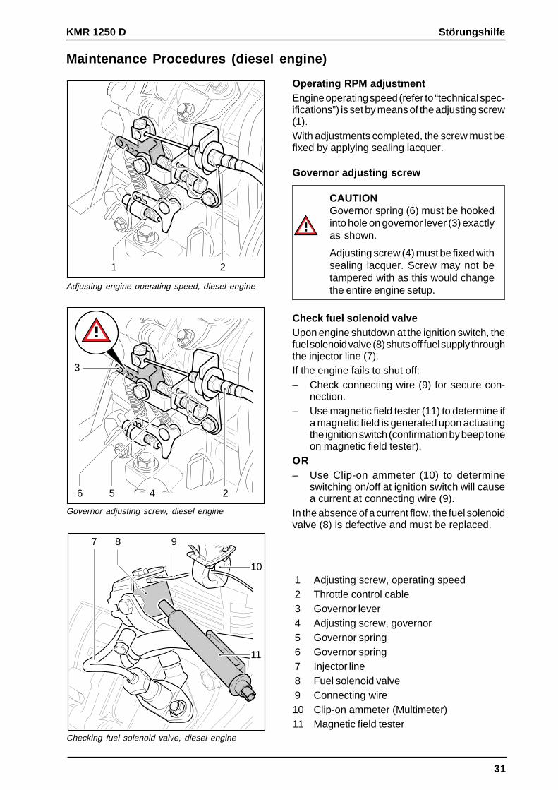
1 Adjusting screw, operating speed2 Throttle control cable3 Governor lever4 Adjusting screw, governor5 Governor spring6 Governor spring7 Injector line8 Fuel solenoid valve9 Connecting wire10 Clip-on ammeter (Multimeter)11 Magnetic field tester
Operating RPM adjustmentEngine operating speed (refer to “technical spec-ifications”) is set by means of the adjusting screw(1).With adjustments completed, the screw must befixed by applying sealing lacquer.
Governor adjusting screw
CAUTIONGovernor spring (6) must be hookedinto hole on governor lever (3) exactlyas shown.
Adjusting screw (4) must be fixed withsealing lacquer. Screw may not betampered with as this would changethe entire engine setup.
Check fuel solenoid valveUpon engine shutdown at the ignition switch, thefuel solenoid valve (8) shuts off fuel supply throughthe injector line (7).If the engine fails to shut off:– Check connecting wire (9) for secure con-
nection.– Use magnetic field tester (11) to determine if
a magnetic field is generated upon actuatingthe ignition switch (confirmation by beep toneon magnetic field tester).
OR– Use Clip-on ammeter (10) to determine
switching on/off at ignition switch will causea current at connecting wire (9).
In the absence of a current flow, the fuel solenoidvalve (8) is defective and must be replaced.
32
Troubleshooting Information KMR 1250 B, LPG, D
Adjust parking brake
Note:With the parking brake released, there mustbe NO braking effect, and the wire and cas-ing cable (1) must be fully relaxed.
The parking brake is required to securely holdthe unit in place when applied on a grade of 25%,and with the unit loaded to capacity.At the same time, tension (X) of the pull spring (7)may not extend by more than 5 to 10 mm (0.20-0.40 in).Brake adjustment is accomplished with adjust-ing nut (5).
- Starting with serial no. 10600, a pullspring is installed on the operating lever(9). This ensures a more easy movementof the brake when the operating lever (9)is actuated.
Check tire pressureUneven tire pressure in the rear wheels causesthe power sweeper to tilt sideways and run lop-sided. The result may be a substandard sweep-ing pattern and the cleaning result is not satisfy-ing.
Check control cablesThe combination of excessive strains at deflec-tion pulleys and repeated road soiling exert con-siderable stresses on mechanical control cables.If required, check cable routing, clean cables,and lubricate with new grease (P/N 6.288-107).
Replace brush roller– Stop and park the machine, engage parking
break.– Using the operating lever, lower brush roller
to center position.– Swing RH side hatch (3) upward.– Remove safety bolt (2) at lower end of fork
head (A, B), and pivot rod toward the rear.– Turn knurled screw (3) counterclockwise.– Remove brush roller arm (4).– Open turn-lock latch (5), and swing hinged
brush roller hatch toward front of unit.– Extract brush roller (6).– Turn brush roller adjustment screw clock-
wise until seated.– Install new brush roller, then replace brush
roller arm.
Note:Ground clearance of raised brush roller mustbe at least 10 mm (0.40 in).
1 Side hatch2 Safety bolt3 Knurled screw4 Brush roller arm5 Turn-lock latch for hinged brush roller
hatch6 Brush roller
34
Troubleshooting Information KMR 1250 B, LPG, D
Check sweeping pattern– Close dust pickup hatch.– Drive mobile sweeper onto dusty surface,
and set parking brake.– Lower brush roller (lever in center position),
and allow to run in place for a few seconds.– Raise brush roller and, with coarse debris
hatch open, reverse a few feet.
Note:Sweeping pattern width should be between30 and 50 mm (1.18-1.97 in). Parallel devia-tion should be less than 15 mm (0.60 in).
Modify sweeping patternThe sweeping pattern is modified by means ofthe central adjustment screw:– To increase pattern contact area: Turn out
adjusting screw counterclockwise (+).– To increase pattern contact area: Turn in
adjustment screw clockwise (–).
Setting sweeping pattern
Modifying sweeping pattern
Set correct sweeping patternA wedge-shaped sweeping pattern may be setby adjusting brush roller suspension on the forkhead (1). This may be accomplished by manip-ulating the fork head on either left-hand or right-hand side, or on both sides.
Brush Roller – Poor Performance
-+
30-50 mm
1
Checking sweeping pattern
1 Fork head
35
KMR 1250 B, LPG, D Troubleshooting Information
Check / replace Brush rollerIn the event that wrap-around string or bandedmaterials block the brush roller, the latter mustbe deinstalled and obstructions removed. Adjustdrive belt tension rollers to allow approx. 10 mmdepression of the respective drive belts.
Check / replace brush roller drive belt (4)This drive belt (4) is located on the vehicle left inthe brush well.If required, replace drive belt after relaxing ten-sion roller (2).
Checking brush roller drive belt
Checking drive belts for sweeper
Removing intermediate shaft
Brush Roller – No Rotation
1 2 3 54
10
8 9
M6
7
12
3 4
1
11
6
Check / replace sweeping drive belt (6)This drive belt (6) is located on the smaller sheaveof the belt pulley (7).- Loosen tension roller (2), remove drive belt
(4) and brush roller arm (3).- Loosen tension rollers (8) and (10), remove
drive belt (9). Disconnect the drive belt (6)from the belt pulley (7).
- Remove drive belt (11).- Loosen intermediate shaft at the flange
mounting (11). The drive belt (6) can now beremoved.
- Place new drive belt (6) on intermediate shaft(12), and on the smaller of the two sheaveson pulley (7).
- Reinstall all previously removed componentsin reversed sequence, then tighten drive belts.
Check drive belt side brushThe side brush is driven by elastic drive belt (5)via intermediate shaft (6).Belt replacement necessitates deinstallation ofintermediate shaft (6) (see page 35, pos. 12).
Check control cable side brushThe control cable (3) is subjected to considera-ble strain through exposure to road soiling. Ifrequired, check cable routing via deflection pul-ley (2) for ease of movement. Clean and lubri-cate with new grease, P/N 6.288-107.
Replace side brushThe side brush is attached to the underside ofthe transmission by means of three bolts.
Side brush drive belt (shown at right)
Checking sweeping patterns
Sweeping pattern – Check / adjust– Sprinkle a level surface evenly with fine sand.
Drive machine onto this surface, and setparking brake.
– Lower side brush, and allow to run for ap-prox. 15 to 30 seconds. Continue by raisingside brush, backing sweeper off test surface.
– The bottom position of the side brush is ad-justed by means of the stop screw (7). Thesweeping pattern should be shaped like ahalf-moon sickle.
– The top position of the side brush is adjustedby manipulating the control cable adjustment(4). Ground clearance of raised side brushmust be approx. 10 to 15 mm (0.40-0.60 in).
Note:The side brush must be easily moved downand up by means of the control lever. Whenoperating, it extends approx. 15 cm (5.9 in)beyond the machine footprint, with exten-sion radius limited by a chain (1).
1 Chain2 Deflection pulley3 Control cable4 Control cable adjustment, ground clear-
Replace dust filterA noticeable deposit of dust at the impeller fanexhaust indicates a poorly installed or defectivedust filter.– Raise debris container (1) to half of its travel,
and secure against dropping.– Unsnap clip fasteners (2) on filter enclosure.– Swing filter enclosure (3) forward, then lift
off.– Unfold hand grip (4), pull out, and unlock by
means of a 90-degree turn.– Remove old dust filter (5).– Insert new dust filter (6).– Return hand grip (4) to original position, and
snap into place.– Install filter enclosure (3), and lock clip fas-
teners (2).
Check rubber sleeveTo prevent filter replacement problems causedby premature corrosion of the locator pin (7) inthe filter receptacle, a rubber sleeve (9) was in-stalled on units with S/N 10518 and up.Defective or missing rubber sleeve (9) should bereplaced or retrofitted (refer to service bulletinno. 1998-045).
Check filter receptacleA noticeable accumulation of dust in the enginecompartment indicates a leaky filter receptacle.The seal ring (1) is defective or the three open-ings on flange (2) are too large, and protrudebeyond the welded ring (3).– Pull off seal ring (1), check and replace as
required.– To seal the openings, apply silicon sealer
around the entire circumference outside thewelded ring (3).
– Replace seal ring (1), ensure proper seat-ing.
Excessive Unit Dusting
1
2
3
7 58 6 4
1 Seal ring2 Flange assembly3 Welded ring (mating rim for seal ring)4 Retainer, control cable5 Coarse debris flap6 Adjusting screw, coarse debris flap7 Control cable5 Sheet metal guard
Check coarse debris flapWhen the coarse dirt flap is open, the brush rollerflings the dirt and dust away toward the frontwithout sweeping it up.The coarse debris flap (5) must open and shuteasily. If required, clean the control cable (7),and lubricate with new grease (P/N 6.288-107)or spray in with teflon spray (P/N 6.288-125).When opened, the gap of the coarse debris flap(5) should be at least 40 mm (1.58 in) wide. In itslowered state, it should trail by approx. 10 to 20mm (0.40-0.80 in).The coarse debris flap (5) is adjusted with theadjusting screw (6).
Note:If the coarse debris flap trails excessively, itmay get caught in the brush roller.
When replacing the control cable (7), care mustbe taken that the retainer (4) remains in the orig-inal horizontal position. This prevents the coarsedebris flap from being pulled inward again aftera short while, breaking the control cable as aresult.To straighten out the retainer (4) or to access theadjusting screw (6), the sheet metal guard (8)must be removed.
39
KMR 1250 B, LPG, D Troubleshooting Information
Check dust pickup– When sweeping on dry ground, the hatch (4)
will be opened with the lever (8) to allow airto enter the impeller fan.
– When sweeping on moist or wet ground, thehatch must be closed again to prevent mois-ture from entering the dust filter.
– When the sweeping debris container israised, it also automatically closes the hatch(4). This prevents dust or objects to be drawninto the large open intake opening (7) in thisstate.
The right-hand side panel conceals a forked,spring-loaded lever (6). When lowered almost tothe bottom position, the container presses thelever forward. This causes the container to belocked up in its end position so that it cannotswing out inadvertently during travel in moun-tainous terrain.The control cable (3) for the hatch (4) is attachedto the lever (6). Pressing the lever backward whileraising the debris container closes the hatch.Pressing the lever forward while lowering thedebris container causes the hatch (4) again to beopened by the coil spring (5).
Note:When the lever is set to the “SUN” position(8), the hatch (4) must be fully open.
The lever (4) operating the hatch must traveleasily enough to allow it to be opened by thecoil spring (5) without problems.
Dust pickup hatch
Container locking lever
Lever, dust pickup close / open
Excessive Unit Dusting
1
2
35
4
7 3
3
6
6
8
1 Housing, impeller fan2 Control cable connected from lever (8) on
instrument panel to hatch (4)3 Control cable connected from lever (6) to
hatch (4)4 Hatch5 Coil spring6 Debris container locking lever7 Intake opening8 Lever, dust pickup close / open
40
Troubleshooting Information KMR 1250 B, LPG, D
Check seal on filter housingUp until S/N 10033, the seal was applied to theimpeller fan inlet. Later, in an effort to improveseal effectiveness, it was attached to the filterhousing.With the filter housing lowered, the seal mustreliably seal off the transition to the housing.
Seal on filter housing
Seals on brush well (rear view with raised container)
Checking tire pressure
Check seals on brush wellThe three seals shown at left serve to seal off thebrush roller well from the debris container.The seals must be replaced as required.
Check impeller fan drive beltThe drive belt (see page 14 pos. 3) is elastic andcannot be adjusted.Replace belt as required.
Excessive Unit Dusting
KARCHER
Check tire pressureA too low tire pressure causes a sinking of thesealing lips and sealing strips and thus a worsesweeping result.(See “Specifications” for tire pressures.)
41
KMR 1250 B, LPG, D Troubleshooting Information
Adjust sealing lips / sealing strips in thesweeping areaThe sealing lips and sealing strips serve essen-tial functions. They maintain the vacuum level inthe sweeping area required for proper function-ing, ensuring dust-free sweeping operations atthe same time. Damaged or worn sealing lips /sealing strips must be replaced.– The front sealing lip (1) cannot be adjusted.
If worn, it should be replaced as soon aspossible.
– Adjust lateral sealing strips (3) to provide aground clearance of approx. 1 to 3 mm (0.04-0.12 in).
– Adjust rear sealing lip (4) with an afterrunningclearance of approx. 10 to 20 mm (0.40-0.80in).
Note:Always consider the weight of the driverwhen doing setup work.
On original units, the lateral sealing lips (3) werecut in such a way that a gap existed betweenthese and the rear sealing lip (4). It providedaccess for fine dust to be drawn into the enginecompartment and engine proper, and enter theengine. Replace older sealing lips with new lat-eral sealing lips (4). They are cut differently atthe back.
Check sealing lips at engine air intakeTogether, the sealing lip (6 and 7) on the air-channel carburetor and the seal on the air chan-nel blower provide dust-free air to be drawn intothe engine.The cross-section of the sealing lip (6 and 7) onthe air-channel carburetor was optimized. Seal-ing strip must be checked for the new cross-section and possible damage, and must be re-placed as required.The seal (8) on the air-channel carburetor mustbe checked for damage and deformation, andreplaced as required.
1 Front sealing lip2 Lateral sealing strip ORIGINAL
3 Lateral sealing strip ORIGINAL
4 Rear sealing lip5 Direction of motion6 Sealing lip ORIGINAL , air-channel carbure-
tor7 Sealing lip REVISED , air-channel carbure-
tor8 Seal, air-channel blower
Adjusting sealing lips & sealing strips
Lateral sealing lip
Sealing lips, air intake
Excessive Unit Dusting
3
2
1
5
10-20 mm
1-3
mm
14
3
5
5
2
3
42
Troubleshooting Information KMR 1250 B, LPG, D
Check terminals (X 10 / X 11) in filter hous-ingPower for the filter cleaning motor is supplied viatwo spring-loaded contact terminals (1).With the debris container lowered, spring-load-ed contact points (1) mounted on the divider bafflemust reliably make connection with rigid matingcontacts (2) on debris container, being depressedby approx. 3 to 4 mm (0.12-0.16 in) in the proc-ess.Clean contacts, adjust contact position by install-ing flat washers, or replace contacts as required.
1 Contacts on divider baffle, spring-loaded2 Contact points on debris container, rigid
Contact points filter housing
Checking M3 motor input voltage
Fuse F1 (filter cleaning motor) on A1 circuit board
Filter cleaning Motor – No Function
Check input voltage at M3 filter cleaningmotorEach time ignition switch is set to “0” position,filter cleaning motor automatically runs for ap-prox. 15 seconds. Pressing filter cleaning buttonwhile engine is running ( ignition switch in “I”position) starts 15-second filter cleaning cycle.To prevent dislodged dust from being drawn intosuction turbine, air flap must be closed before-hand.– Raise debris container.– Press filter cleaning button.– Check voltage on contact terminals X10/X11.– If there is no voltage present, start by check-
ing fuse F1 (10 A) on A1 circuit board, thencheck terminals X2/X3.
– If a voltage is present without shaker motorrunning, check motor for ohmic resistance.
1 2
A1
V
X4 X5
X2 X3X1 X6
-F1(10 A)
X11X10
-K1-F2(7,5A)
-M3
M
A1
F1(10A)
43
KMR 1250 B, LPG, D Troubleshooting Information
Note:Troubleshooting may proceed with engineshut off.
Check hydraulic unit- Check F3 fuse. The F3 fuse protects only the
hydraulic unit. It is located beneath the elec-trical box.
- Using a voltmeter, check input voltage of M2hydraulic unit between thick red cable (pos-itive polarity, 10 sq. mm cross-section) andmatching black cable (negative polarity).
- Using the voltmeter, check input voltage onmotor relay. Perform measurement with ig-nition switch set to position “I”.With buttons S5 and S8 actuated, controlvoltage must be present at relay.
If measurements removed components and produce a voltage reading but hydraulic motoris not running, the hydraulic unit is defective andmust be replaced.
Note:The wiring connections between relay andhydraulic motor are not shown in the electri-cal circuit diagram.
Check solenoid valves (Y1 / Y2)Measurements and : Using the voltmeter,check input voltage on solenoid valves Y1 andY2 at connecting plug.If voltage is present, solenoid valves will switchwith an audible click.If there is no voltage present, check power sup-ply, vehicle ground connections and both but-tons (S5 and S8) for proper functioning.The solenoid valves are not available as spareparts. If a defect is found, the entire hydraulicassembly must be replaced.
Check hydraulic unitBy contamination within the hydraulic system,the debris container can no longer be raised aftera brief operating period. The fine orifices in thehydraulic unit are blocked.As the hydraulic unit is maintenance-free andshould not be opened. It must be replaced as anassembly if required.With the debris container lowered, the hydraulicfluid level should be approx. 2 to 3 cm (0.80-1.18in) below the edge of the filler neck.
Note:Extremely clean working conditions andwork habits are a prerequisite for workingon the hydraulic system.
After a replacement, all hydraulic system com-ponents automatically purge themselves whenthe raising mechanism is actuated repeatedly.As a result, only the lifting cylinder must be purgedseparately.
Check hydraulic fluidWhen the unit is cold, the use of nonstandardhydraulic fluid will cause the debris container tobe raised only very slowly.The correct choice of hydraulic fluid (see “Spec-ifications”) facilitates working at temperatures to-10 °C (14 °F) without difficulty.
Hydraulic unit
Bleeding (purging) air from lifting cylinder
Debris Container – Very Slow Ascent
Purge lifting cylinder– Raise container to the top position, and sup-
port to prevent inadvertent descent.– Press Raise Container button again, while at
the same time cracking the purge screw onthe lifting cylinder. When all air has escapedand hydraulic fluid exits without bubbles, tight-en purge screw.
– Wipe up hydraulic fluid runoff, and check flu-id level in reservoir.
DANGER – FATAL INJURY HAZARDRaised container must be reliablysupported while personnel is workingunderneath.
Hydraulic unit
Y1
Y2
1
Y1
Y2
1
45
KMR 1250 B, LPG, D Troubleshooting Information
Hydraulic unit w/ pressure relief valve
Adjusting pressure relief valve
Adjust pressure relief valveRaise empty or full debris container to maximumattainable height (two-hand operation) . In thisposition hold on the two buttons and measurethe current draw of the hydraulic unit (see “tech-nical specification”). The current draw providesa measure of the opening pressure set on thepressure relief valve.
Hydraulic unit,adjust pressure relief valve ORIGINAL
– Remove hydraulic unit but do not discon-nect hydraulic hoses .
– Holding valve insert (3) with wrench, unscrewcap of pressure relief valve (1). The capconceals the valve adjusting screw.
– Continue to hold valve insert (3) with wrench,loosen lock nut (2) on valve adjusting screw.
– Using a flat screwdriver, turn adjusting screw:One-half CW turn increases current draw byroughly 4 to 5 A (approx. 10 bar, approx. 145psi).
– Finish by tightening lock nut on adjustingscrew, again installing screw cap (1).
– Install hydraulic unit: Perform function test,and measure current draw.
Adjust steering free playWear and tear and stretching of the steering chain(1) may cause excessive steering free play.If steering free play becomes too large, the steeringchain must be tighted, replaced as requiredTighten steering chain– Loosen nuts of mounting bolts (2), and tighten
chain (1) by shifting steering column (3) in elon-gated holes.
– Retighten mounting nuts.
Replace chain– Loosen nuts of mounting bolts (2), and shift
steering column (3) in elongated holes farenough to allow removal of steering chain (1).
– Install new steering chain, ensuring that frontwheel points straight ahead when steering wheelis in center (non-deflected) position.
Noise levelMeasured in accordance with DIN 45 635 T36 and DIN 45 648 standardsat operating speed of 2700 RPM, subjective reading at operator position is 79,5 dB(A).
KMR 1250 B, LPG, D
60
Special Tools
Ignition spark tester, gasoline & LP gas engine
Mechanical tachometer (all engines)
Digital tachometer for gasoline and LP gas engine
Digital tachometer for gasolineand LP gas engineFrom a distance of approx. 100 mm (4 in.), pointthis digital tachometer at spark plug wire, andswitch on tester. Set to 4-Stroke (“4-Taktmotor”)position to read speed of running engine.
P/N 6.803-012
Mechanical tachometer for gasoline, LPgas, and diesel engineEngine speed is determined by reading enginevibrations. Tachometer is placed at suitable lo-cation on engine (e.g., valve cover). When res-onance spring is extended until deflection is larg-est with engine running, scale indicates enginespeed.
P/N 6.491-361
Ignition spark tester(for gasoline and LP gas engine)Remove spark plug connector from spark plugand push onto spark tester. Connect clamp tosuitable conductor (e.g., engine cooling fins). Ifignition is in good working condition, crankingengine with starter will produce visible sparksbetween points of spark tester.
P/N 6.491-359
KMR 1250 B, LPG, D
61
Special Tools
Multimeter w/ test probes
Spark plug wrench for gasoline and LP gas engine
MultimeterMultimeter must meet the following minimum re-quirements:– AC / DC measuring (amps, volts)– Diode test function– Resistance measuring (0-15 kΩ)
P/N 6.803-022
Spark plug wrenchfor gasoline and LP gas engineUnscrews spark plug from cylinder head.
P/N 6.815-088
Magnetic field tester
Magnetic field testerFor testing magnetic fields on solenoid valves.
P/N 6.803-003
DC/AC
kHz400V600V1000A400A
OFF
VOLTCRAFT
PeakHold
113 CLAMP METER
COM
400
HzV
KMR 1250 B, LPG, D
62
Dual-function hand pump
Leak detection spray
Dual-function hand pumpFor checking integrity of diaphragm in LP gasregulators (LP gas engines). Hand pump fea-tures switchover valve to generate vacuum orpressure (Pressure / Vacuum mode).
P/N 6.473-400
Leak detection spray (for LP gas engines)Indispensable when checking LP gas systemfor leaks.
P/N 6.282-033
CO Tester for LPG engine
CO testerMeasures CO component in exhaust emissions.
– Measuring range > 2% CO content– Resolution: 0.01%– Includes suction pump– LCD display
Excessive Steering Free Play 46Excessive Unit Dusting 37, 38, 39, 40, 41
F
Filter 49Filter cleaning control 51, 53, 55Filter cleaning motor 51, 53, 55
No Function 42Flange 13Float chamber equalization 9Float system 9Front wheel 6, 15Fuel feed line 12, 13Fuel tank for KMR B / D 6Full load operation 9Fuse 58
Alternator 51, 53, 55control voltage 51, 53, 55Filter cleaning motor 51, 53, 55Hydraulic unit 51, 53, 55
G
Gas cylinder (LP Gas) 6Gas regulator 11Gas system 11Gasoline Engine
(HONDA GX 270) 8, 9
H
Head lights 6Headlight switch 7Headlights 51, 53, 55HONDA GX 270 5Horn 51, 53, 55Hydraulic Block Diagram 48, 49Hydraulic Unit
No Function 43Hydraulic unit 15, 48, 49, 51, 53, 55, 59
Fails to Turn Engine 16, 17, 18Turns Engine but Engine Fails to Start 19, 20
Steering 58Steering and Drive Power 14Steering wheel 6, 14, 15Suction and filtering system 4Sweeping mechanism 58Sweeping pattern – Check / adjust 36Sweeping system 4, 15Switch
Headlights 51, 53, 55Seat contact 51, 53, 55
T
tank capacity 59Technical specifications 58, 59Throttle lever 7Throttle valve 48, 49Tighten steering chain 46Tilting cylinder w/ gas strut assist 48, 49Tires 58Top up engine oil 26, 30Transmission drive belt 21two-hand operation 4, 7, 43, 45