24
FLOWAY ACCESS 03- 2019 EN75466664.02 Instruction manual Manuel d'instructions Benutzerhandbuch Manual de instrucciones Instructiehandboek

FLO
WAY
ACC
ESS
03- 2019
EN75466664.02
Instruction manualManuel d'instructionsBenutzerhandbuchManual de instruccionesInstructiehandboek

EN - 2
Original text: French version
CONTENTS PAGE
1. RECEIPT 3
2. HANDLING 3
3. DESCRIPTION OF THE UNIT & TECHNICAL CHARACTERISTICS 4
4. INSTALLATION & CONNECTIONS 9
5. SYSTEM START-UP 16
6. MAINTENANCE/SERVICE INTERVALS 17
7. PROBLEMS/CAUSES/SOLUTIONS 20
8. TESTS AND GUARANTEES 20

EN
EN - 3
For your safety, we recommend the use of PPE (Personal Protective Equipment)
1. RECEIPT
The installation and maintenance operations must be performed by qualified and experienced personnel.This appliance is not designed to be used by persons (including children) with limited physical, sensory or mental capabilities, or by persons with insufficient experience or knowledge, unless they are being supervised by a person responsible for their safety or have received instructions on the use of the appliance from such a person.Children should be supervised to ensure that they do not play with the unit.Follow the operating precautions to the letter when working on the unit. Labels have been placed on the unit to remind you of the safety instructions.As a general rule, follow all applicable safety regulations and standards. Damage to the dual flow air handling unit will be disregarded in the event of failure to follow the instructions in this document.
Each unit has a name plate bearing an identification number. This number must be quoted in all correspondence.In accordance with Article 133-3 of the French Code of Commerce, the recipient is entirely responsible for checking the condition of the goods received. In the event of missing items, the customer must provide the exact number of parcels delivered. Any damaged or missing items must be specified on the delivery note in the presence of the driver before signing the delivery note. This information must be confirmed to the Carrier by registered letter within three business days. The comments "conditional" and "pending unwrapping" shall have no value. The client must unwrap the goods in the presence of the driver. Claims must be made at the time of delivery and be described in detail.The unit must be stored in its packaging and sheltered from weather.The machines are supplied as a single unit.
2. HANDLING
The unit can be handled by slings, lifting beam or stacker. In all cases, the lifting point has to be at the base of the unit. The centre of gravity is at the centre of the unit.
This operation will be performed by qualified personnel.
The unit must be handled with care, and only in the horizontal position. If the unit is handled by a lifting beam + slings, tubes need to be placed in the holes provided in the support feet.Ensure that the crane hook adapter is large enough to prevent the belts applying any pressure to the AHU casing. Furthermore, ensure that the steel tubes are secured to prevent any movement.
COLISPACKAGE
If the above-mentioned lifting methods cannot be used, the unit may be lifted using a forklift truck, taking great care not to dent the lower panel (use forks of a sufficient length).
Follow the applicable handling rules.
The units must be set down directly on flat, level ground. The flatness value must be the best possible, around one per thousand. Under normal conditions of use, there is no need to fix the unit to the floor, unless it is being installed outside of the building.The unit's support feet must be standing fully on their contact surface. It is important to allow sufficient service space to facilitate maintenance operations.
EN - 4
3. DESCRIPTION OF THE UNIT & TECHNICAL CHARACTERISTICS
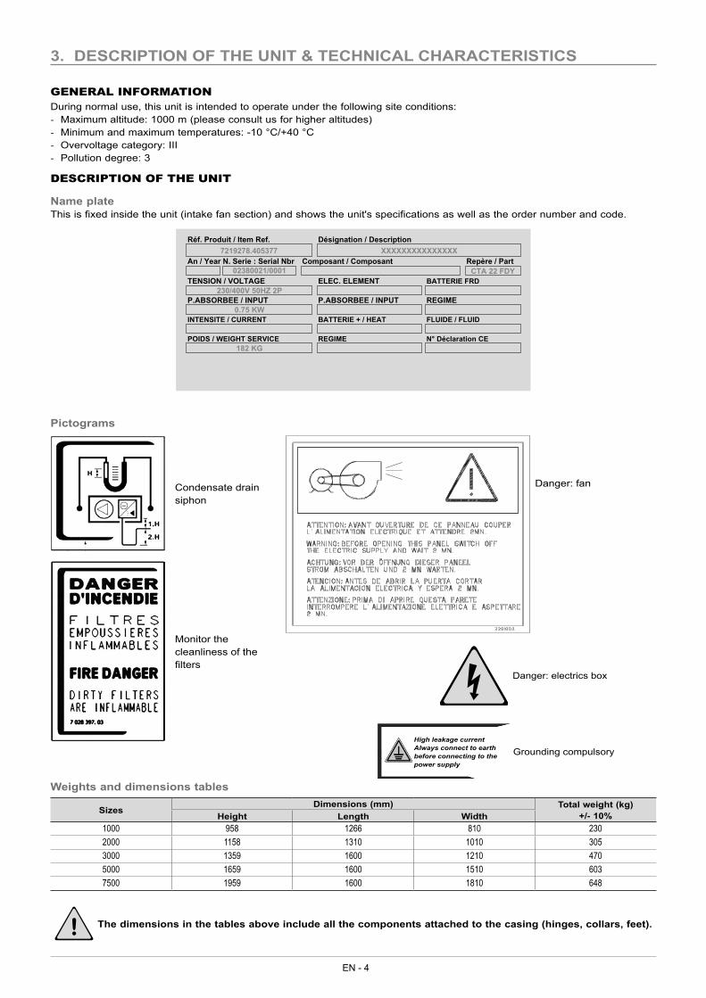
GENERAL INFORMATIONDuring normal use, this unit is intended to operate under the following site conditions: - Maximum altitude: 1000 m (please consult us for higher altitudes) - Minimum and maximum temperatures: -10 °C/+40 °C - Overvoltage category: III - Pollution degree: 3
DESCRIPTION OF THE UNIT
Name plateThis is fixed inside the unit (intake fan section) and shows the unit's specifications as well as the order number and code.
02380021/0001
7219278.405377
182 KG
0.75 KW
230/400V 50HZ 2P
XXXXXXXXXXXXXXX
CTA 22 FDYTENSION / VOLTAGE
P.ABSORBEE / INPUT
INTENSITE / CURRENT
POIDS / WEIGHT SERVICE
Réf. Produit / Item Ref.
An / Year N. Serie : Serial Nbr
ELEC. ELEMENT
P.ABSORBEE / INPUT
BATTERIE + / HEAT
REGIME
Désignation / Description
Composant / Composant
BATTERIE FRD
REGIME
FLUIDE / FLUID
N° Déclaration CE
Repère / Part
Pictograms
Danger: fan
Danger: electrics box
Condensate drain siphon
Monitor the cleanliness of the filters
Weights and dimensions tables
SizesDimensions (mm) Total weight (kg)
+/- 10%Height Length Width1000 958 1266 810 2302000 1158 1310 1010 3053000 1359 1600 1210 4705000 1659 1600 1510 6037500 1959 1600 1810 648
The dimensions in the tables above include all the components attached to the casing (hinges, collars, feet).
Grounding compulsoryHigh leakage currentAlways connect to earth before connecting to the power supply
EN
EN - 5
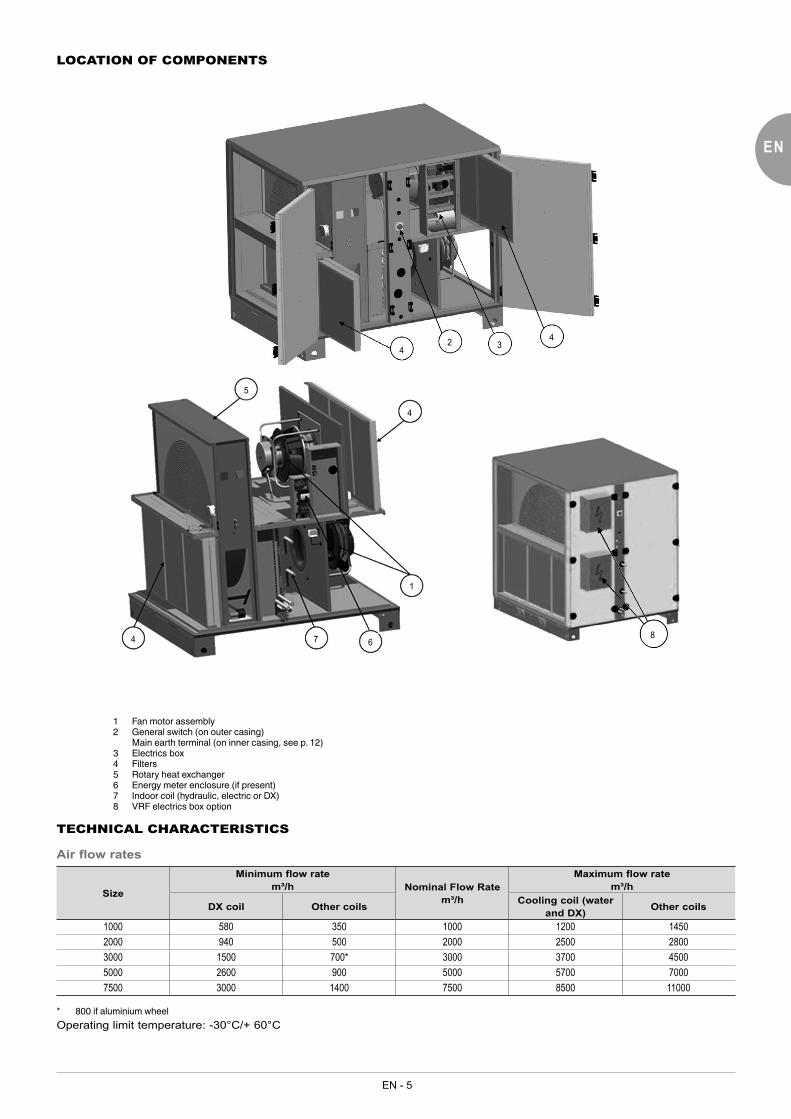
LOCATION OF COMPONENTS
432
4
7 6
1
4
5
4 8
1 Fan motor assembly2 General switch (on outer casing) Main earth terminal (on inner casing, see p. 12)3 Electrics box4 Filters5 Rotary heat exchanger6 Energy meter enclosure (if present)7 Indoor coil (hydraulic, electric or DX)8 VRF electrics box option
TECHNICAL CHARACTERISTICS
Air flow rates
Size
Minimum flow ratem³/h Nominal Flow Rate
m³/h
Maximum flow ratem³/h
DX coil Other coils Cooling coil (water and DX) Other coils
1000 580 350 1000 1200 14502000 940 500 2000 2500 28003000 1500 700* 3000 3700 45005000 2600 900 5000 5700 70007500 3000 1400 7500 8500 11000
* 800 if aluminium wheelOperating limit temperature: -30°C/+ 60°C

EN - 6
Filters
M5 HEE filter F7 HEE filter F9 HEE filter
Thickness: 48 mm Thickness: 48 mm Thickness: 48 mmFire rating: M1 Fire rating: M1 Fire rating: M1
Single filtrationSizes
1000 2000 3000 5000 7500Filter Dimensions x Number of cells/air flow (704x327x48) x 1 (452x435x48) x 2 (552x535x48) x 2 (466x685x48) x 3 (566x835x48) x 3
Dual filtrationWhen dual-stage filtration is installed, the two stages of cells are installed on the same runner.
Recommended fouling level valueThe pressure switches installed enable a filter fouling warning to be issued. They are factory-set, based on:• the unit size• the selected flow rate• the filter efficiencyThe graphs below give values which enable the actuation threshold for the pressure switches to be defined based on the selected flow rate.
M5
ΔP (P
a)
Qv (m³/h)
0102030405060708090
100
0 1000 2000 3000 4000 5000 6000 7000 8000 9000
1000 2000 3000 5000 7500
F7
0
20
40
60
80
100
120
140
0 1000 2000 3000 4000 5000 6000 7000 8000 9000
ΔP (P
a)
Qv (m³/h)
1000 2000 3000 5000 7500
F9
0
50
100
150
200
250
300
0 1000 2000 3000 4000 5000 6000 7000 8000 9000
ΔP (P
a)
Qv (m³/h)
1000 2000 3000 5000 7500

EN
EN - 7
M5 + F7
0
50
100
150
200
250
0 1000 2000 3000 4000 5000 6000 7000 8000 9000
ΔP (P
a)
Qv (m³/h)
1000 2000 3000 5000 7500
M5 + F9
050
100150200250300350400
0 1000 2000 3000 4000 5000 6000 7000 8000 9000
ΔP (P
a)
Qv (m³/h)
1000 2000 3000 5000 7500
Fan motor assembly
EC motorThis fan motor assembly is a direct coupling type plug fan.The unit is equipped with 2 fan motor assemblies: 1 at the intake and 1 at the exhaust. Sizes 1000, 2000 and 3000 are available in an aluminium or polypropylene version; refer to the equipment selection sheet to find out the type of fan used.
Aluminium wheel
Sizes1000 2000 3000 5000 7500
Wheel Ø 250 280 310 355 450Quantity 2 2 2 2 2
Max. power (W) 2 x 500 2 x 1000 2 x 1800 2 x 2680 2 x 3030Max. current (A) 2 x 2.2 2 x 1.6 2 x 2.8 2 x 4.1 2 x 4.7
Polypropylene wheel
Sizes1000 2000 3000
Wheel Ø 250 310 400Quantity 2 2 2
Max. power (W) 2 x 520 2 x 790 2 x 1320Max. current (A) 2 x 2.3 2 x 1.3 2 x 2.1
Heat recovery unitConstant speed rotary heat exchanger controlled by the unit's control system.

EN - 8
Options and accessories
Support feet and accessoriesTo obtain a greater clearance height, fit the adjustable feet (30 to 100 mm) underneath the standard feet.
Cylinder
Reinforcement plate
CO2 sensorThe CO2 sensor must be positioned on the return air duct, so that it can measure the CO2 level emitted from the part(s) treated.This sensor is supplied as a spare part and the manual for this is included in its packaging.
Operating principle:
To configure the CO2 level activation threshold, refer to the information on air quality for the town/city in which the AHU is installed.
CO2 concentration scale and the effects on humans:
CO2 concentration Effect on humans
380 - 480 ppm Normal atmospheric level600 - 800 ppm Correct level for enclosed spaces
1000 - 1100 ppm Tolerable level for enclosed spaces5000 ppm Upper limit for 8 hours of exposure
The CO2 sensor provides an operating range of 0 to 2000 ppm and must be installed in a duct (refer to the attached supplier instructions).
Constant pressure sensorConstant pressure is only controlled on theflow of fresh air being supplied (if the optional constant pressure kit has been purchased).The fresh air fan is controlled by the signal from this pressure sensor in the duct.The exhaust air flow is controlled by the flow rate signal read off the flow of fresh air, and may vary according to a factor M (0.5 – 1.5).Two pressure values can be configured: Nominal pressure and Reduced pressure.The duct pressure sensor must be positioned on the supply air inlet duct at a distance:D = 2 Dh (hydraulic Ø)• If the duct is circular, Dh = Ø of the duct• If the duct is rectangular
Dh = 2 x L x l L+l
CO2 sensor

EN
EN - 9
Changeover thermostat for mixed coil:The customer is responsible for installation on the hydraulic system. The changeover thermostat installed on the pipe must be integrated into the insulation of the hydraulic pipe.
Technical characteristics
Min. WINTER temp.: 28 °CMin. SUMMER temp.: 18 °CBreaking capacity: 5(3) A.Cable length: 2500 mm
Damper
The damper is not protected against the weather if the canopy option has not been selected.
4. INSTALLATION & CONNECTIONS
The installation of the equipment must comply with the regulations and standards of the recipient country.Ensure all electrical components are earthed.The equipment must not be accessible to the public.
Special recommendations:• Connections must not place mechanical stresses on the unit.• Keep all inspection doors closed while the unit is operating• It must not be possible to access the fans via the connection frames for the unit. If there is a direct air intake, a grille must be
fitted, as a minimum.• If fitted outdoors, the units must be installed so as to withstand the climate conditions in the installation location (risk of snow:
height from ground/risk of wind: suitable mountings, gooseneck type electric connection to the unit, etc.).
Flexible sleeve
INSTALLATION OUTDOORSThe installation of a dual-flow unit outdoors requires a roof and a canopy to be fitted; these are usually supplied mounted* and adapted to suit each configuration.(* supplied in kit form if delivery of the elements assembled is not possible)
Fitting the roofsThe roofs for units are designed to provide sufficient protection against adverse weather conditions, as they overlap the edge of the unit by 80 mm.
BLACK wire (winter)
IVORY wire (shared)
BLUE wire (do not use)

EN - 10
Fitting procedure:1. Affix the foam gasket along the length of the unit (50 x 20 foam gasket).2. Fix the roof panel(s) along the entire length of the unit.
50x20 foam gasket bonded for roof curvature
3. Assemble the roof on the unit as per the following diagramØ 4.8 sealed rivet or Ø 4.2 self-drilling screw+ sealed washer
Side rail
Ø 22.2 blanking cover
Roof
Ø 4.8 self-drilling screw
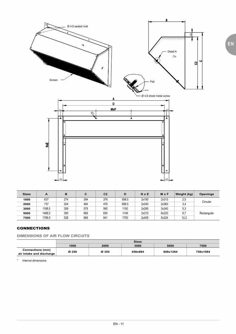
Fitting the canopy without damperThe upper panel will be assembled on the two side panels using screws, washers and nuts or sealed rivets. Also fit the protective screen during installation.Fix a sealing gasket around the edge of the canopy which will be in contact with the unit and apply mastic if necessary.
EN
EN - 11
Ø 4.8 sealed rivet
Screen
Detail A
Flat
Ø 4.8 sheet metal screw
Sizes A B C C2 D N x E M x F Weight (kg) Openings
1000 637 274 394 376 598.5 2x190 2x313 2,5Circular
2000 737 304 494 476 698,5 2x240 2x363 3,43000 1188,5 358 579 560 1150 2x265 3x340 5,3
Rectangular5000 1488,5 390 669 650 1149 2x310 6x220 6,77500 1788,5 528 869 841 1750 2x405 5x324 12,2
CONNECTIONS
DIMENSIONS OF AIR FLOW CIRCUITSSizes
1000 2000 3000 5000 7500Connections (mm)
air intake and discharge Ø 250 Ø 355 458x984 608x1284 758x1584
* Internal dimensions

EN - 12
DIMENSION OF THE HYDRAULIC CIRCUITS (Indoor hydraulic coil)
VALVE CONNECTION
Heating/cooling assembly
O-ring
2-WAY VALVE
THREE-WAY VALVE
OUT
IN
O-ring
OUT
Coi
l con
nect
ions
Coi
l con
nect
ions
IN
The diameter of the condensate tube on all the pans is 16 mm
1 row coilSizes
1000 2000 3000 5000 7500Ø connections (mm)
4-way valveValve inlet G 1/2" G 1/2" G 3/4" G 3/4" G 1"
Valve outlet G 1/2" G 1/2" G 3/4" G 3/4" G 1"1/2
2-row coilSizes
1000 2000 3000 5000 7500Ø connections (mm)
4-way valveValve inlet G 3/4" G 3/4" G 3/4" G 3/4" G 1"
Valve outlet G 3/4" G 3/4" G 3/4" G 3/4" G 1"1/2
EN
EN - 13
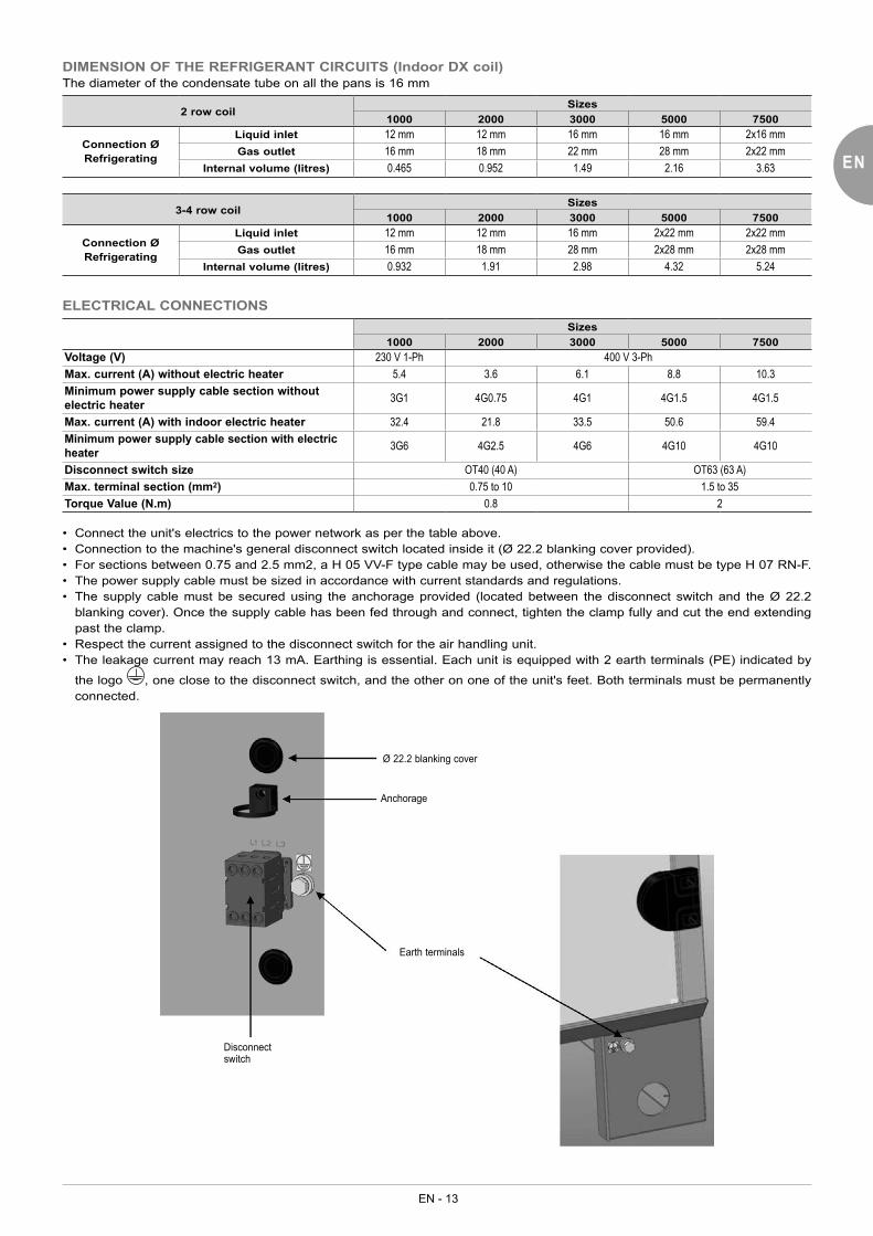
DIMENSION OF THE REFRIGERANT CIRCUITS (Indoor DX coil)The diameter of the condensate tube on all the pans is 16 mm
2 row coilSizes
1000 2000 3000 5000 7500
Connection ØRefrigerating
Liquid inlet 12 mm 12 mm 16 mm 16 mm 2x16 mmGas outlet 16 mm 18 mm 22 mm 28 mm 2x22 mm
Internal volume (litres) 0.465 0.952 1.49 2.16 3.63
3-4 row coilSizes
1000 2000 3000 5000 7500
Connection ØRefrigerating
Liquid inlet 12 mm 12 mm 16 mm 2x22 mm 2x22 mmGas outlet 16 mm 18 mm 28 mm 2x28 mm 2x28 mm
Internal volume (litres) 0.932 1.91 2.98 4.32 5.24
ELECTRICAL CONNECTIONSSizes
1000 2000 3000 5000 7500Voltage (V) 230 V 1-Ph 400 V 3-PhMax. current (A) without electric heater 5.4 3.6 6.1 8.8 10.3Minimum power supply cable section without electric heater 3G1 4G0.75 4G1 4G1.5 4G1.5
Max. current (A) with indoor electric heater 32.4 21.8 33.5 50.6 59.4Minimum power supply cable section with electric heater 3G6 4G2.5 4G6 4G10 4G10
Disconnect switch size OT40 (40 A) OT63 (63 A)Max. terminal section (mm2) 0.75 to 10 1.5 to 35Torque Value (N.m) 0.8 2
• Connect the unit's electrics to the power network as per the table above.• Connection to the machine's general disconnect switch located inside it (Ø 22.2 blanking cover provided).• For sections between 0.75 and 2.5 mm2, a H 05 VV-F type cable may be used, otherwise the cable must be type H 07 RN-F.• The power supply cable must be sized in accordance with current standards and regulations.• The supply cable must be secured using the anchorage provided (located between the disconnect switch and the Ø 22.2
blanking cover). Once the supply cable has been fed through and connect, tighten the clamp fully and cut the end extending past the clamp.
• Respect the current assigned to the disconnect switch for the air handling unit.• The leakage current may reach 13 mA. Earthing is essential. Each unit is equipped with 2 earth terminals (PE) indicated by
the logo , one close to the disconnect switch, and the other on one of the unit's feet. Both terminals must be permanently connected.
Ø 22.2 blanking cover
Anchorage
Earth terminals
Disconnect switch

EN - 14
IDENTIFICATION OF TERMINAL STRIP OPTIONS
PRESSOSTAT FILTRE INTRODUCTION
PRESSURE SWITCH SUPPLY AIR FILTER
PRESSOSTAT FILTRE EXTRACTION
PRESSURE SWITCH EXHAUST AIR FILTER
EXHAUST AIR TEMPERATURE
SUPPLY AIR TEMPERATURE
FRESH AIR TEMPERATURE
-X2
1X2:2 14DEFAUT INCENDIE
FIRE DEFAULT 2X2:1 15
3 20SYNTHESE DEFAUT
DEFAULT SYNTHESIS 4 21
7:GND 7
PRESSION GAINE / QUALITE AIRDUCT PRESSURE / AIR QUALITY
8B1:OUT 8
9B1:IN 3
10X2:11 14
ECO / CONFORTECO / COMFORT 1
1X2:10 17
12X2:13 14
COMMANDE A DISTANCEREMOTE CONTROL 1
3X2:12 18
14 3CAV42:1enuT-ht
ALIMENTATION TH TUNESUPPLY TH TUNE 1
5 4DNG:1enuT-ht
W9 21Xf8:1 241
REGISTRE 1DAMPER 1
22Xf8:2 42
W10 23Xf9:1 241
REGISTRE 2DAMPER 2
24Xf9:2 42
W6 31PP1:1 221
32PP1:2 52
W7 33PP2:1 221
34PP2:2 62
35B6:B1 7
TEMPERATURE EXTRACTION
36B6:B2 9
37B4:B1 7
TEMPERATURE INTRODUCTION
38B4:B2 10
39B5:B1 11
TEMPERATURE AIR NEUF
40B5:B2 12
"Customer" cable grommet
NB: the maximum section of the stripped wire is Ø 1.5 mm and Ø 0.5 mm for a wire with an end-piece.*
■ Fire detection: 2 wires
Machine terminal block Notes Inlet/Outlet
X2 _ b-1 Fire detection activationDry contact Digital inputs
X2 _ b-2
Contact normally closed
■ Fault feedback: 2 wires
Machine terminal block Notes Inlet/Outlet
X2 _ b-3 Fault summaryDry contact (shared b-4) Digital outputs
X2 _ b-4 Common
■ Constant intake duct pressure sensor/IAQ control sensor: 3 wires
Machine terminal block Notes Inlet/Outlet
X2 _ b-7 Fire detection activationAnalogue inputs
X2 _ b-8 0-10V pressure control signal (OUT) or Sensor/Transmitter rear probe 0-10V active sensor
X2 _ b-9 Sensor 24V supply
FIRE FAULT
FAULT SUMMARY
AIR QUALITY/DUCT PRESSURE
ECO / COMFORT
REMOTE CONTROL
TH TUNE POWER SUPPLY
DAMPER 1
DAMPER 2
INTAKE FILTER PRESSURE SWITCH
EXHAUST FILTER PRESSURE SWITCH
EXHAUST TEMPERATURE
INTAKE TEMPERATURE
FRESH AIR TEMPERATURE

EN
EN - 15
1 2 3+I GND V
3 fils
Alimentation24 Vdc
Afficheur régulateur ouautomate type actif
Sortie 0-10 V
- -
-
+
+
+
+4 5 6 7
3
2
1
IN
OUT
GNDtechn. 3 fils
CO2 in duct: CO112-ANA Duct pressure: CP51
■ Eco/Comfort contact: 2 wires
Machine terminal block Notes Inlet/Outlet
X2 _ b-10 Eco/Comfort mode controlDry contact (shared b-10) Digital inputs
X2 _ b-11
■ Remote On/Off: 2 wires
Machine terminal block Notes Inlet/Outlet
X2 _ b-12 Unit ON/OFF monitoringDry contact (shared b-12) Digital inputs
X2 _ b-13
■ Th-Tune power supply: 2 wires
Machine terminal block Notes Inlet/Outlet
X2 _ b-14 24V power supplypLAN
X2 _ b-15 Ground
■ Presence of changeover coil: 2 wires
Machine terminal block Notes Inlet/Outlet
X2 _ b-16 C/O thermostat black wireDigital inputs
X2 _ b-17 C/O thermostat white wire
The changeover thermostat must be positioned on the "customer" hydraulic pipe, on the "fluid entering the coil" side (so as to be in the insulation).Contact open: normal operation in cooling modeContact closed: operation in heating mode (contact closed from 28 °C)
Controller display or active controller
3 wires
techn. 3 wires
24 Vdc supply
0-10 V output
EN - 16
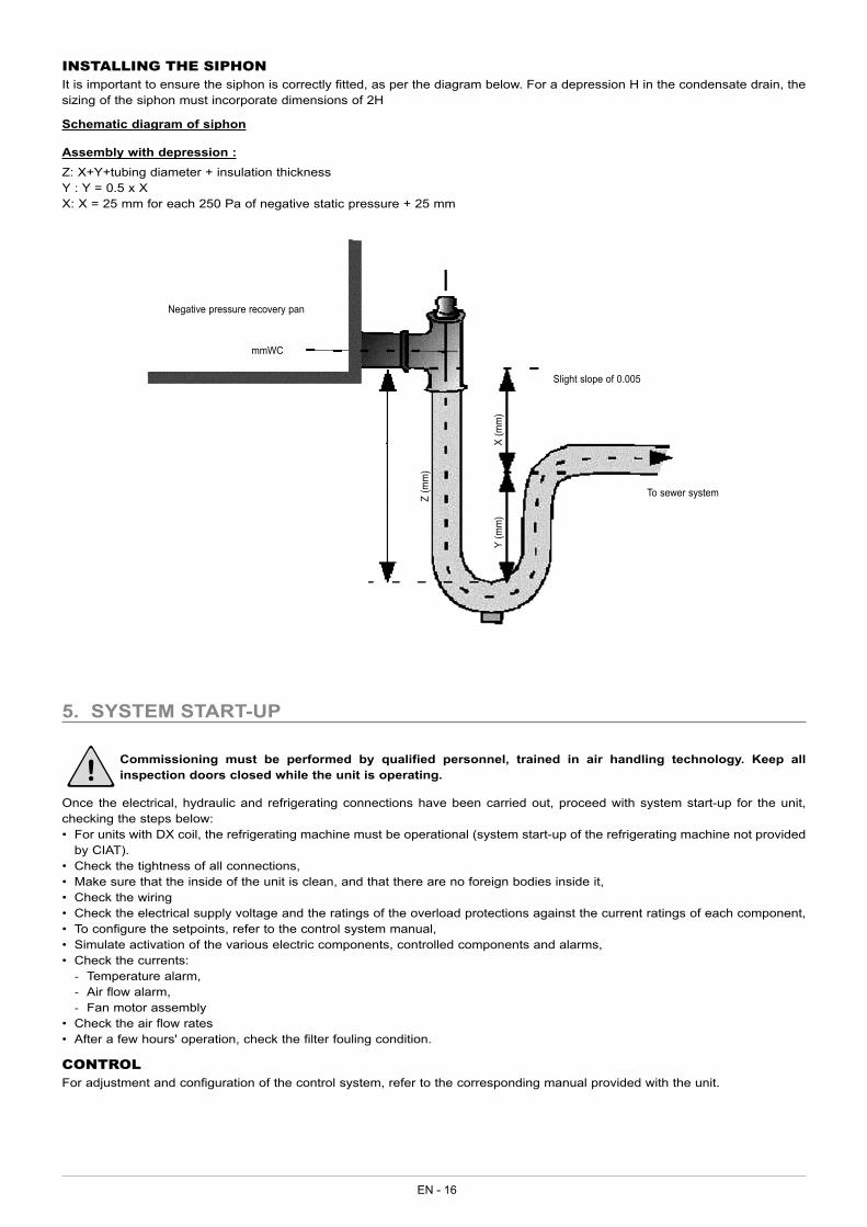
INSTALLING THE SIPHONIt is important to ensure the siphon is correctly fitted, as per the diagram below. For a depression H in the condensate drain, the sizing of the siphon must incorporate dimensions of 2H
Schematic diagram of siphon
Assembly with depression :Z: X+Y+tubing diameter + insulation thicknessY : Y = 0.5 x XX: X = 25 mm for each 250 Pa of negative static pressure + 25 mm
mmWC
Slight slope of 0.005
To sewer systemZ (m
m)
Y (m
m)
X (m
m)
Negative pressure recovery pan
5. SYSTEM START-UP
Commissioning must be performed by qualified personnel, trained in air handling technology. Keep all inspection doors closed while the unit is operating.
Once the electrical, hydraulic and refrigerating connections have been carried out, proceed with system start-up for the unit, checking the steps below:• For units with DX coil, the refrigerating machine must be operational (system start-up of the refrigerating machine not provided
by CIAT).• Check the tightness of all connections,• Make sure that the inside of the unit is clean, and that there are no foreign bodies inside it,• Check the wiring• Check the electrical supply voltage and the ratings of the overload protections against the current ratings of each component,• To configure the setpoints, refer to the control system manual,• Simulate activation of the various electric components, controlled components and alarms,• Check the currents:
- Temperature alarm, - Air flow alarm, - Fan motor assembly
• Check the air flow rates• After a few hours' operation, check the filter fouling condition.
CONTROLFor adjustment and configuration of the control system, refer to the corresponding manual provided with the unit.
EN
EN - 17
6. MAINTENANCE/SERVICE INTERVALS
Switch off the electrical supply to the air handling unit before carrying out any work
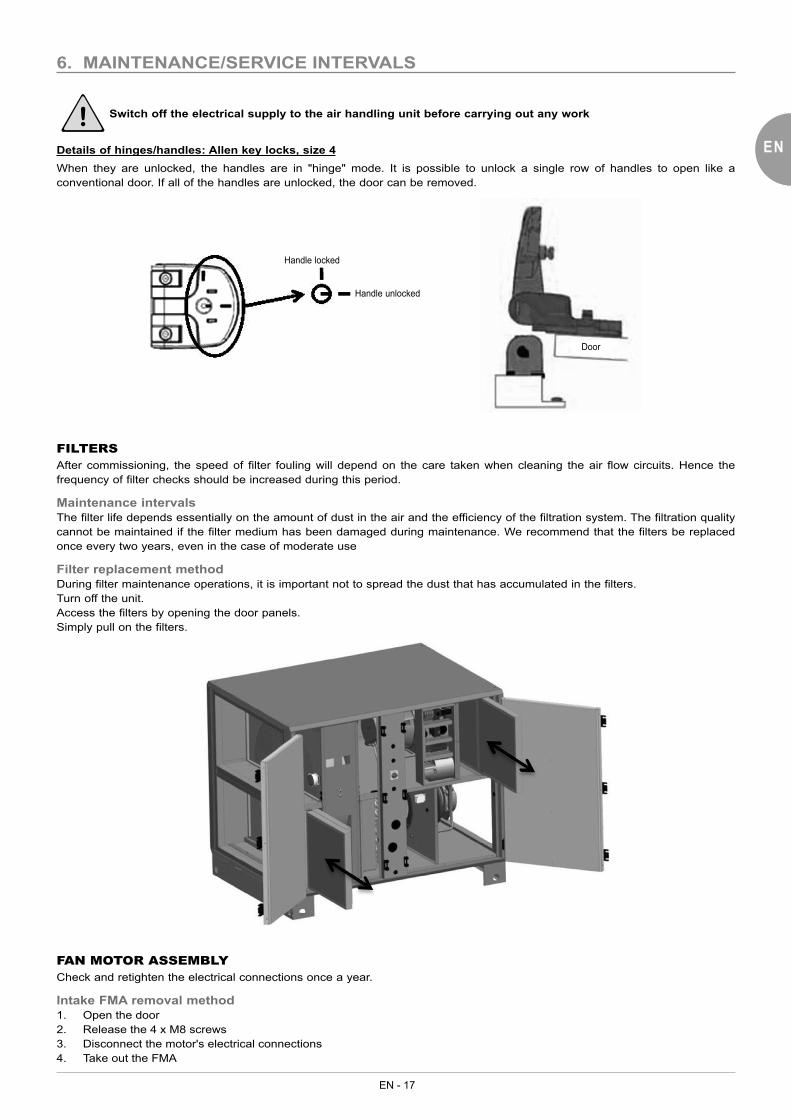
Details of hinges/handles: Allen key locks, size 4When they are unlocked, the handles are in "hinge" mode. It is possible to unlock a single row of handles to open like a conventional door. If all of the handles are unlocked, the door can be removed.
Handle locked
Handle unlocked
Door
FILTERSAfter commissioning, the speed of filter fouling will depend on the care taken when cleaning the air flow circuits. Hence the frequency of filter checks should be increased during this period.
Maintenance intervalsThe filter life depends essentially on the amount of dust in the air and the efficiency of the filtration system. The filtration quality cannot be maintained if the filter medium has been damaged during maintenance. We recommend that the filters be replaced once every two years, even in the case of moderate use
Filter replacement methodDuring filter maintenance operations, it is important not to spread the dust that has accumulated in the filters.Turn off the unit.Access the filters by opening the door panels.Simply pull on the filters.
FAN MOTOR ASSEMBLYCheck and retighten the electrical connections once a year.
Intake FMA removal method1. Open the door2. Release the 4 x M8 screws3. Disconnect the motor's electrical connections4. Take out the FMA

EN - 18
Exhaust FMA removal method
1. Open the door 2. Remove the upper and lower fixings from the electrics box
3. Move the electrics box; a sufficient length of cable is provided
4. Disconnect the various quick connectors
5. Provide sufficient clearance 6. Remove the 4 x M8 screws

EN
EN - 19
7. Disconnect the motor's electrical connections 8. Take out the FMA
To refit, perform the operations in reverse order.Check that the box and the connectors are secure before commissioning.
HEAT RECOVERY UNIT
Rotary heat exchangersCheck the rotation speed once a year.When stationary, the rotary heat exchangers accumulate dust and moisture at their lowest point.Schedule cleaning during prolonged stoppages.Check the permanently lubricated bearings once a year.
Wheel consumptionSizes
1000 2000 3000 5000 7500
Constant speedPower (W) 25 25 40 90 180Voltage (V) 230 V 1-Ph 400 V 3-Ph
ELECTRICS BOXRetighten the connections twice a year.Visually inspect the components, wires and cables.
ELECTRIC HEATERSThe electric heater requires very little maintenance. However, the following checks are necessary:Visually inspect the heating elements, wires and connection cables after every 1500 hours of operation.Check and retighten the connections once or twice a year.
HYDRAULIC COILSThe hydraulic coil requires very little maintenance as it is protected by the filter.
DX COILThe DX coil requires very little maintenance as it is protected by the filter.
SERVICE INTERVALSRegular maintenance will keep the unit running at optimum performance. The values given in the table below are provided for guidance only. They do not take into account individual factors that can lengthen or shorten the unit's service life.
EN - 20
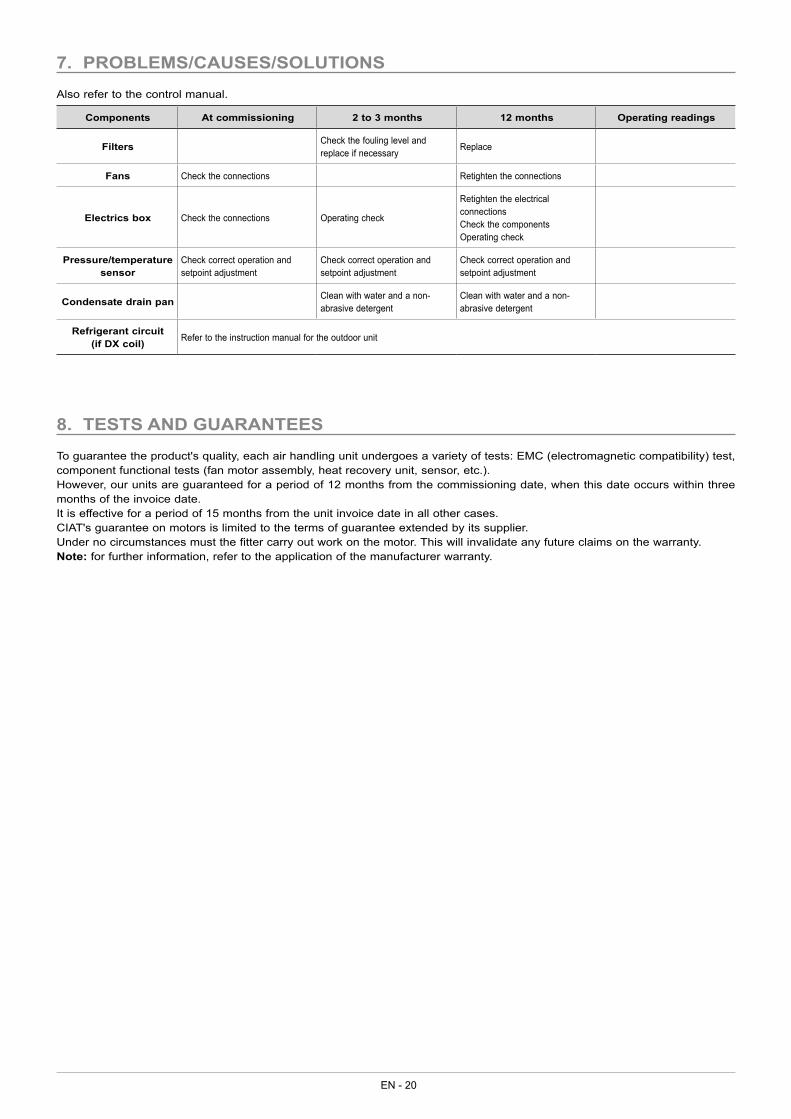
7. PROBLEMS/CAUSES/SOLUTIONS
Also refer to the control manual.
Components At commissioning 2 to 3 months 12 months Operating readings
Filters Check the fouling level and replace if necessary Replace
Fans Check the connections Retighten the connections
Electrics box Check the connections Operating check
Retighten the electrical connectionsCheck the componentsOperating check
Pressure/temperature sensor
Check correct operation and setpoint adjustment
Check correct operation and setpoint adjustment
Check correct operation and setpoint adjustment
Condensate drain pan Clean with water and a non-abrasive detergent
Clean with water and a non-abrasive detergent
Refrigerant circuit (if DX coil) Refer to the instruction manual for the outdoor unit
8. TESTS AND GUARANTEES
To guarantee the product's quality, each air handling unit undergoes a variety of tests: EMC (electromagnetic compatibility) test, component functional tests (fan motor assembly, heat recovery unit, sensor, etc.).However, our units are guaranteed for a period of 12 months from the commissioning date, when this date occurs within three months of the invoice date.It is effective for a period of 15 months from the unit invoice date in all other cases.CIAT's guarantee on motors is limited to the terms of guarantee extended by its supplier.Under no circumstances must the fitter carry out work on the motor. This will invalidate any future claims on the warranty.Note: for further information, refer to the application of the manufacturer warranty.

EN
EN - 21

EN - 22

EN
EN - 23

Head officeAvenue Jean Falconnier B.P. 14
01350 Culoz - FranceTel.: +33 (0)4 79 42 42 42Fax: +33 (0)4 79 42 42 10
www.ciat.com
Compagnie Industrielled’Applications Thermiques
Corporation with a capital of €26,728,480Bourg-en-Bresse Register of Trade and Companies
no. B 545.620.114
Non-contractual document.As part of our continuous drive to improve our products, CIAT reserves the right
to make any technical modifications without prior notice.
CIAT Servicewww.ciat.com


