Page 1
IMPLEMENTATION GUIDE
Copyright © 2010, Juniper Networks, Inc. 1
ENABLING CLASS OF SERVICE ON EX SERIES SWITCHES IN A CAMPUS LAN
Although Juniper Networks has attempted to provide accurate information in this guide, Juniper Networks does not warrant or guarantee the accuracy of the information provided herein. Third party product descriptions and related technical details provided in this document are for information purposes only and such products are not supported by Juniper Networks. All information provided in this guide is provided “as is”, with all faults, and without warranty of any kind, either expressed or implied or statutory. Juniper Networks and its suppliers hereby disclaim all warranties related to this guide and the information contained herein, whether expressed or implied of statutory including, without limitation, those of merchantability, fitness for a particular purpose and noninfringement, or arising from a course of dealing, usage, or trade practice.
Page 2
2 Copyright © 2010, Juniper Networks, Inc.
IMPLEMENTATION GUIDE -Enabling Class of Service on EX Series Switches in a Campus LAN
Table of Contents
Introduction . . . . . . . . . . . . . . . . . . . . . . . . . . . . . . . . . . . . . . . . . . . . . . . . . . . . . . . . . . . . . . . . . . . . . . . . . . . . . . . . . . . . . . . . . . . . . . . . . . . . . . . . . . . . . . . . 4
Scope . . . . . . . . . . . . . . . . . . . . . . . . . . . . . . . . . . . . . . . . . . . . . . . . . . . . . . . . . . . . . . . . . . . . . . . . . . . . . . . . . . . . . . . . . . . . . . . . . . . . . . . . . . . . . . . . . . . . . . 4
Design Considerations . . . . . . . . . . . . . . . . . . . . . . . . . . . . . . . . . . . . . . . . . . . . . . . . . . . . . . . . . . . . . . . . . . . . . . . . . . . . . . . . . . . . . . . . . . . . . . . . . . . . . . 4
Why CoS? . . . . . . . . . . . . . . . . . . . . . . . . . . . . . . . . . . . . . . . . . . . . . . . . . . . . . . . . . . . . . . . . . . . . . . . . . . . . . . . . . . . . . . . . . . . . . . . . . . . . . . . . . . . . . . . 4
CoS vs. Quality of Service (QoS) . . . . . . . . . . . . . . . . . . . . . . . . . . . . . . . . . . . . . . . . . . . . . . . . . . . . . . . . . . . . . . . . . . . . . . . . . . . . . . . . . . . . . . . . . 4
Network Architecture. . . . . . . . . . . . . . . . . . . . . . . . . . . . . . . . . . . . . . . . . . . . . . . . . . . . . . . . . . . . . . . . . . . . . . . . . . . . . . . . . . . . . . . . . . . . . . . . . . . . . 4
Hardware Requirements . . . . . . . . . . . . . . . . . . . . . . . . . . . . . . . . . . . . . . . . . . . . . . . . . . . . . . . . . . . . . . . . . . . . . . . . . . . . . . . . . . . . . . . . . . . . . . . . . 5
Software Requirements . . . . . . . . . . . . . . . . . . . . . . . . . . . . . . . . . . . . . . . . . . . . . . . . . . . . . . . . . . . . . . . . . . . . . . . . . . . . . . . . . . . . . . . . . . . . . . . . . . 5
Implementation . . . . . . . . . . . . . . . . . . . . . . . . . . . . . . . . . . . . . . . . . . . . . . . . . . . . . . . . . . . . . . . . . . . . . . . . . . . . . . . . . . . . . . . . . . . . . . . . . . . . . . . . . . . . 5
CoS on EX Series Switches . . . . . . . . . . . . . . . . . . . . . . . . . . . . . . . . . . . . . . . . . . . . . . . . . . . . . . . . . . . . . . . . . . . . . . . . . . . . . . . . . . . . . . . . . . . . . . . 5
Buffering . . . . . . . . . . . . . . . . . . . . . . . . . . . . . . . . . . . . . . . . . . . . . . . . . . . . . . . . . . . . . . . . . . . . . . . . . . . . . . . . . . . . . . . . . . . . . . . . . . . . . . . . . . . . . . 7
EX2200/EX3200/EX4200 Switches . . . . . . . . . . . . . . . . . . . . . . . . . . . . . . . . . . . . . . . . . . . . . . . . . . . . . . . . . . . . . . . . . . . . . . . . . . . . . . . . . . . 7
EX8200 Line . . . . . . . . . . . . . . . . . . . . . . . . . . . . . . . . . . . . . . . . . . . . . . . . . . . . . . . . . . . . . . . . . . . . . . . . . . . . . . . . . . . . . . . . . . . . . . . . . . . . . . . . . . 8
Deploying CoS . . . . . . . . . . . . . . . . . . . . . . . . . . . . . . . . . . . . . . . . . . . . . . . . . . . . . . . . . . . . . . . . . . . . . . . . . . . . . . . . . . . . . . . . . . . . . . . . . . . . . . . . . . . 8
Trust and Untrust Domains . . . . . . . . . . . . . . . . . . . . . . . . . . . . . . . . . . . . . . . . . . . . . . . . . . . . . . . . . . . . . . . . . . . . . . . . . . . . . . . . . . . . . . . . . . . . 8
Edge Devices . . . . . . . . . . . . . . . . . . . . . . . . . . . . . . . . . . . . . . . . . . . . . . . . . . . . . . . . . . . . . . . . . . . . . . . . . . . . . . . . . . . . . . . . . . . . . . . . . . . . . . . . . . 9
Core Devices. . . . . . . . . . . . . . . . . . . . . . . . . . . . . . . . . . . . . . . . . . . . . . . . . . . . . . . . . . . . . . . . . . . . . . . . . . . . . . . . . . . . . . . . . . . . . . . . . . . . . . . . . . 10
Deployment Scenarios . . . . . . . . . . . . . . . . . . . . . . . . . . . . . . . . . . . . . . . . . . . . . . . . . . . . . . . . . . . . . . . . . . . . . . . . . . . . . . . . . . . . . . . . . . . . . . . . . . 10
Unicast Deployment . . . . . . . . . . . . . . . . . . . . . . . . . . . . . . . . . . . . . . . . . . . . . . . . . . . . . . . . . . . . . . . . . . . . . . . . . . . . . . . . . . . . . . . . . . . . . . . . . . 10
1.1 Configuring Edge Devices . . . . . . . . . . . . . . . . . . . . . . . . . . . . . . . . . . . . . . . . . . . . . . . . . . . . . . . . . . . . . . . . . . . . . . . . . . . . . . . . . . . . . . . . . . . . 12
1.1.0 Forwarding class configuration . . . . . . . . . . . . . . . . . . . . . . . . . . . . . . . . . . . . . . . . . . . . . . . . . . . . . . . . . . . . . . . . . . . . . . . . . . . . . . . . . . 12
1.1.1 BA classifier table . . . . . . . . . . . . . . . . . . . . . . . . . . . . . . . . . . . . . . . . . . . . . . . . . . . . . . . . . . . . . . . . . . . . . . . . . . . . . . . . . . . . . . . . . . . . . . . . 12
1.1.2 Multifield classifier . . . . . . . . . . . . . . . . . . . . . . . . . . . . . . . . . . . . . . . . . . . . . . . . . . . . . . . . . . . . . . . . . . . . . . . . . . . . . . . . . . . . . . . . . . . . . . . 13
1.1.3 Drop profile . . . . . . . . . . . . . . . . . . . . . . . . . . . . . . . . . . . . . . . . . . . . . . . . . . . . . . . . . . . . . . . . . . . . . . . . . . . . . . . . . . . . . . . . . . . . . . . . . . . . . . 14
1.1.4 Schedulers . . . . . . . . . . . . . . . . . . . . . . . . . . . . . . . . . . . . . . . . . . . . . . . . . . . . . . . . . . . . . . . . . . . . . . . . . . . . . . . . . . . . . . . . . . . . . . . . . . . . . . 14
1.1.5 Scheduler map . . . . . . . . . . . . . . . . . . . . . . . . . . . . . . . . . . . . . . . . . . . . . . . . . . . . . . . . . . . . . . . . . . . . . . . . . . . . . . . . . . . . . . . . . . . . . . . . . . 15
1.1.6 Rewrite rule table . . . . . . . . . . . . . . . . . . . . . . . . . . . . . . . . . . . . . . . . . . . . . . . . . . . . . . . . . . . . . . . . . . . . . . . . . . . . . . . . . . . . . . . . . . . . . . . . 15
1.1.7 Binding CoS to interfaces. . . . . . . . . . . . . . . . . . . . . . . . . . . . . . . . . . . . . . . . . . . . . . . . . . . . . . . . . . . . . . . . . . . . . . . . . . . . . . . . . . . . . . . . . 16
1.1.8 Binding multifield classifier to interface . . . . . . . . . . . . . . . . . . . . . . . . . . . . . . . . . . . . . . . . . . . . . . . . . . . . . . . . . . . . . . . . . . . . . . . . . . .17
1.2 Configuring core devices . . . . . . . . . . . . . . . . . . . . . . . . . . . . . . . . . . . . . . . . . . . . . . . . . . . . . . . . . . . . . . . . . . . . . . . . . . . . . . . . . . . . . . . . . . . . . 18
1.2.0 Drop profile . . . . . . . . . . . . . . . . . . . . . . . . . . . . . . . . . . . . . . . . . . . . . . . . . . . . . . . . . . . . . . . . . . . . . . . . . . . . . . . . . . . . . . . . . . . . . . . . . . . . . 18
1.2.1 Schedulers. . . . . . . . . . . . . . . . . . . . . . . . . . . . . . . . . . . . . . . . . . . . . . . . . . . . . . . . . . . . . . . . . . . . . . . . . . . . . . . . . . . . . . . . . . . . . . . . . . . . . . . 18
1.2.2 Scheduler map profile . . . . . . . . . . . . . . . . . . . . . . . . . . . . . . . . . . . . . . . . . . . . . . . . . . . . . . . . . . . . . . . . . . . . . . . . . . . . . . . . . . . . . . . . . . . 19
1.2.3 Binding CoS to interfaces . . . . . . . . . . . . . . . . . . . . . . . . . . . . . . . . . . . . . . . . . . . . . . . . . . . . . . . . . . . . . . . . . . . . . . . . . . . . . . . . . . . . . . . . 19
Unicast/Multicast Deployment . . . . . . . . . . . . . . . . . . . . . . . . . . . . . . . . . . . . . . . . . . . . . . . . . . . . . . . . . . . . . . . . . . . . . . . . . . . . . . . . . . . . . . . 19
Page 3
Copyright © 2010, Juniper Networks, Inc. 3
IMPLEMENTATION GUIDE - Enabling Class of Service on EX Series Switches in a Campus LAN
Table of Figures
Figure 1: EX Series CoS stages . . . . . . . . . . . . . . . . . . . . . . . . . . . . . . . . . . . . . . . . . . . . . . . . . . . . . . . . . . . . . . . . . . . . . . . . . . . . . . . . . . . . . . . . . . . . . . 6
Figure 2: EX2200/EX3200/EX4200 PFE buffer allocation . . . . . . . . . . . . . . . . . . . . . . . . . . . . . . . . . . . . . . . . . . . . . . . . . . . . . . . . . . . . . . . . . . 7
Figure 3: CoS boundaries . . . . . . . . . . . . . . . . . . . . . . . . . . . . . . . . . . . . . . . . . . . . . . . . . . . . . . . . . . . . . . . . . . . . . . . . . . . . . . . . . . . . . . . . . . . . . . . . . . . 9
Figure 4: Campus LAN topology. . . . . . . . . . . . . . . . . . . . . . . . . . . . . . . . . . . . . . . . . . . . . . . . . . . . . . . . . . . . . . . . . . . . . . . . . . . . . . . . . . . . . . . . . . . . . 11
Figure 5: Unicast/multicast topology . . . . . . . . . . . . . . . . . . . . . . . . . . . . . . . . . . . . . . . . . . . . . . . . . . . . . . . . . . . . . . . . . . . . . . . . . . . . . . . . . . . . . .20
2.1 Configuration of core devices . . . . . . . . . . . . . . . . . . . . . . . . . . . . . . . . . . . . . . . . . . . . . . . . . . . . . . . . . . . . . . . . . . . . . . . . . . . . . . . . . . . . . . . . 21
2.1.0 Multicast on EX8200 line switches . . . . . . . . . . . . . . . . . . . . . . . . . . . . . . . . . . . . . . . . . . . . . . . . . . . . . . . . . . . . . . . . . . . . . . . . . . . . . . 21
2.1.1 Configuring classifier for multicast traffic . . . . . . . . . . . . . . . . . . . . . . . . . . . . . . . . . . . . . . . . . . . . . . . . . . . . . . . . . . . . . . . . . . . . . . . . . 22
2.1.2 Configuring the scheduler profile for multicast queue . . . . . . . . . . . . . . . . . . . . . . . . . . . . . . . . . . . . . . . . . . . . . . . . . . . . . . . . . . . . . 23
2.1.3 Configuring the scheduler map for the multicast queue . . . . . . . . . . . . . . . . . . . . . . . . . . . . . . . . . . . . . . . . . . . . . . . . . . . . . . . . . . 23
2.1.4 Binding the classifier and scheduler map, and moving the default queue for broadcast, L2 multicast, and
unknown unicast to a different queue . . . . . . . . . . . . . . . . . . . . . . . . . . . . . . . . . . . . . . . . . . . . . . . . . . . . . . . . . . . . . . . . . . . . . . . . . . . . . . . . . 23
2.1.5 Scheduler and scheduler map . . . . . . . . . . . . . . . . . . . . . . . . . . . . . . . . . . . . . . . . . . . . . . . . . . . . . . . . . . . . . . . . . . . . . . . . . . . . . . . . . . . 24
Multifield Classifier for Multicast Traffic . . . . . . . . . . . . . . . . . . . . . . . . . . . . . . . . . . . . . . . . . . . . . . . . . . . . . . . . . . . . . . . . . . . . . . . . . . . . . . . . . . 25
CoS Validation . . . . . . . . . . . . . . . . . . . . . . . . . . . . . . . . . . . . . . . . . . . . . . . . . . . . . . . . . . . . . . . . . . . . . . . . . . . . . . . . . . . . . . . . . . . . . . . . . . . . . . . . . . 26
Summary . . . . . . . . . . . . . . . . . . . . . . . . . . . . . . . . . . . . . . . . . . . . . . . . . . . . . . . . . . . . . . . . . . . . . . . . . . . . . . . . . . . . . . . . . . . . . . . . . . . . . . . . . . . . . . . . . 26
References . . . . . . . . . . . . . . . . . . . . . . . . . . . . . . . . . . . . . . . . . . . . . . . . . . . . . . . . . . . . . . . . . . . . . . . . . . . . . . . . . . . . . . . . . . . . . . . . . . . . . . . . . . . . . . . . 26
Appendix 1-A: Unicast Edge Device Configuration . . . . . . . . . . . . . . . . . . . . . . . . . . . . . . . . . . . . . . . . . . . . . . . . . . . . . . . . . . . . . . . . . . . . . . . . . . 27
Appendix 1-B: Unicast Core Device Configuration . . . . . . . . . . . . . . . . . . . . . . . . . . . . . . . . . . . . . . . . . . . . . . . . . . . . . . . . . . . . . . . . . . . . . . . . . . 31
Appendix 2: Unicast/Multicast Core Device Configuration . . . . . . . . . . . . . . . . . . . . . . . . . . . . . . . . . . . . . . . . . . . . . . . . . . . . . . . . . . . . . . . . . . 33
About Juniper Networks . . . . . . . . . . . . . . . . . . . . . . . . . . . . . . . . . . . . . . . . . . . . . . . . . . . . . . . . . . . . . . . . . . . . . . . . . . . . . . . . . . . . . . . . . . . . . . . . . . . 36
Page 4
4 Copyright © 2010, Juniper Networks, Inc.
IMPLEMENTATION GUIDE -Enabling Class of Service on EX Series Switches in a Campus LAN
Introduction
Class of service (CoS) is a complex and challenging feature to deploy in any network. Questions such as how many queues to
configure or how much buffer or bandwidth should be allocated need to be answered when deploying CoS, especially across
a campus network. This implementation guide will describe where and how to configure CoS in a campus LAN network with
Juniper Networks® EX Series Ethernet Switches.
Scope
This document will focus solely on deploying CoS with EX Series switches (the Juniper Networks EX2200 line, EX3200 line,
EX4200 line in a standalone or Virtual Chassis configuration, and the EX8200 line of Ethernet switches) for both unicast
and multicast in a campus LAN two-tier network. In addition, this document will cover the configuration for access and core
switches, providing tips and caveats where applicable.
The target audiences for this document are Juniper systems engineers (SEs), professional services organizations, and
customers, although every effort has been made to make this document appeal to the widest possible Juniper audience. It
is assumed that the reader is familiar with Juniper Networks Junos® operating system and its command-line interface (CLI),
with general switching terminology, and has a basic understanding of 802.1p and DiffServ code point (DSCP).
Design Considerations
Why CoS?
Before getting into the specifics, the first question that needs to be addressed is, “Does CoS need to be enabled on my
network?” Unfortunately, there is never a simple yes or no answer to this question as it depends on a number of factors. CoS
decisions shouldn’t be based solely on reported packet drops on interfaces; decisions should also consider issues such as
end user Quality of Experience (QoE) and whether an application needs to meet certain service requirements. Other factors
to consider include whether end users are noticing application performance problems such as timeouts, long delays, or voice
or video quality issues like choppy or clipped transmissions and pixilated or constantly buffering video streams. When these
problems do occur, CoS is recommended as a potential solution.
QoE problems are not simply caused by insufficient bandwidth; instead, they are the culmination of multiple issues such as
network design, architecture of the box, and traffic patterns. More often than not, problems are the result of contention on
ports with a many-to-one relationship, speed differences, or packets getting stuck behind other application packets.
CoS vs. Quality of Service (QoS)
CoS is often used synonymously with QoS. It is important to understand that, while similar, CoS and QoS are actually
different technologies.
QoS is a subset of traffic engineering, which allows network administrators to manage resources and bandwidth during a
time of congestion. It does not guarantee quality services but rather reserves network resources to help achieve the service
quality outlined by the application.
CoS, on the other hand, defines a traffic group with common service requirements such as traffic priorities, latency, jitter, etc.,
while QoS manages the network resources to ensure that these service levels are met for these groups of traffic.
Junos OS models CoS as the software classifies like traffic into class groups (forwarding classes). Each forwarding class will
have quality requirements for specific services.
Network Architecture
Key advantages of deploying CoS with EX Series switches in a campus network are the common Junos OS across all EX
Series platforms, wire-rate performance for IPv4 and IPv6 unicast and multicast for all packet sizes, and high port densities.
The combination of wire-rate performance and high port counts allows the user to simplify the network by moving from a
three-tier to a two-tier architecture. Reducing the number of network layers translates into lower latency, as there are fewer
hops in the network. The network can even be simplified further with Virtual Chassis technology. However, this document
will not discuss campus architecture or designing networks with Virtual Chassis technology. For more information on campus
architecture, please refer to the Campus LAN Reference Architecture at www.juniper.net/us/en/local/pdf/reference-
architectures/8030005-en.pdf.
Page 5
Copyright © 2010, Juniper Networks, Inc. 5
IMPLEMENTATION GUIDE - Enabling Class of Service on EX Series Switches in a Campus LAN
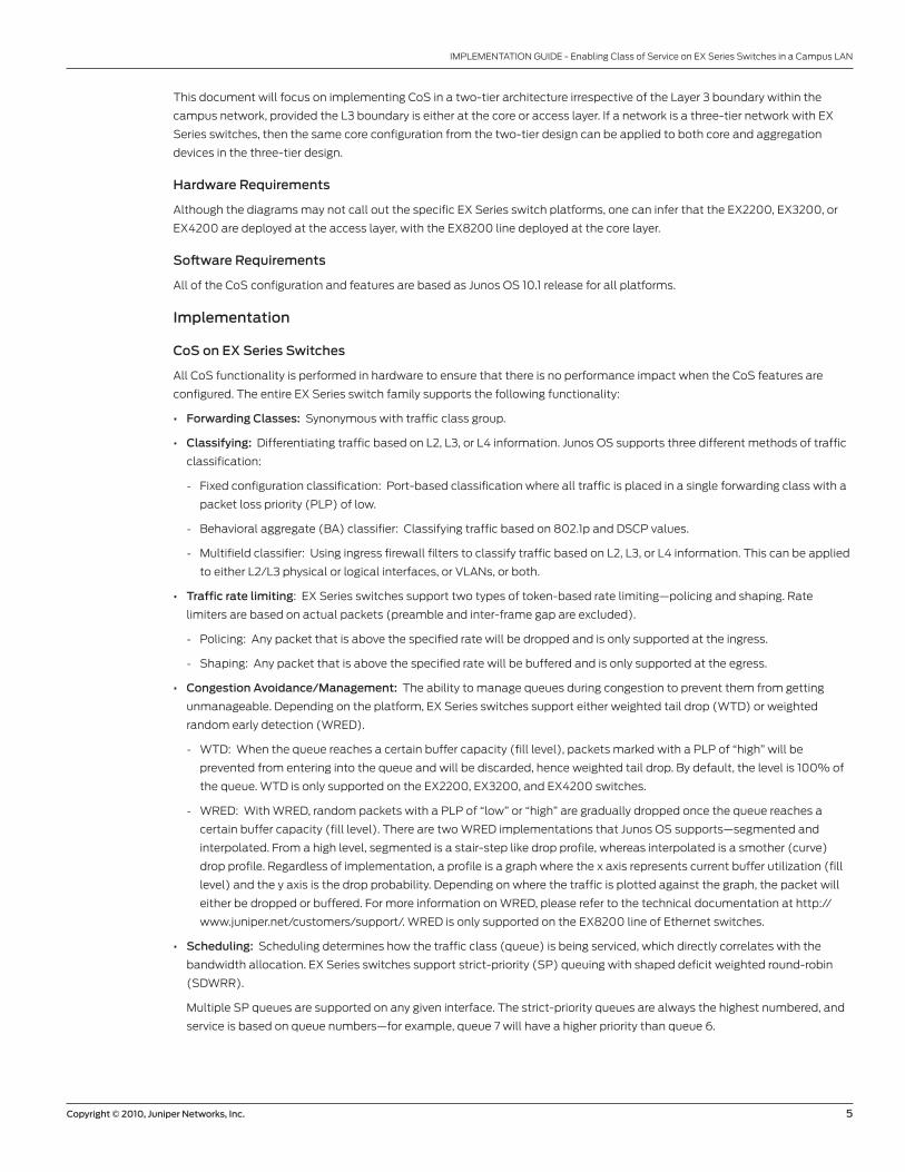
This document will focus on implementing CoS in a two-tier architecture irrespective of the Layer 3 boundary within the
campus network, provided the L3 boundary is either at the core or access layer. If a network is a three-tier network with EX
Series switches, then the same core configuration from the two-tier design can be applied to both core and aggregation
devices in the three-tier design.
Hardware Requirements
Although the diagrams may not call out the specific EX Series switch platforms, one can infer that the EX2200, EX3200, or
EX4200 are deployed at the access layer, with the EX8200 line deployed at the core layer.
Software Requirements
All of the CoS configuration and features are based as Junos OS 10.1 release for all platforms.
Implementation
CoS on EX Series Switches
All CoS functionality is performed in hardware to ensure that there is no performance impact when the CoS features are
configured. The entire EX Series switch family supports the following functionality:
• Forwarding Classes: Synonymous with traffic class group.
• Classifying: Differentiating traffic based on L2, L3, or L4 information. Junos OS supports three different methods of traffic
classification:
- Fixed configuration classification: Port-based classification where all traffic is placed in a single forwarding class with a
packet loss priority (PLP) of low.
- Behavioral aggregate (BA) classifier: Classifying traffic based on 802.1p and DSCP values.
- Multifield classifier: Using ingress firewall filters to classify traffic based on L2, L3, or L4 information. This can be applied
to either L2/L3 physical or logical interfaces, or VLANs, or both.
• Traffic rate limiting: EX Series switches support two types of token-based rate limiting—policing and shaping. Rate
limiters are based on actual packets (preamble and inter-frame gap are excluded).
- Policing: Any packet that is above the specified rate will be dropped and is only supported at the ingress.
- Shaping: Any packet that is above the specified rate will be buffered and is only supported at the egress.
• Congestion Avoidance/Management: The ability to manage queues during congestion to prevent them from getting
unmanageable. Depending on the platform, EX Series switches support either weighted tail drop (WTD) or weighted
random early detection (WRED).
- WTD: When the queue reaches a certain buffer capacity (fill level), packets marked with a PLP of “high” will be
prevented from entering into the queue and will be discarded, hence weighted tail drop. By default, the level is 100% of
the queue. WTD is only supported on the EX2200, EX3200, and EX4200 switches.
- WRED: With WRED, random packets with a PLP of “low” or “high” are gradually dropped once the queue reaches a
certain buffer capacity (fill level). There are two WRED implementations that Junos OS supports—segmented and
interpolated. From a high level, segmented is a stair-step like drop profile, whereas interpolated is a smother (curve)
drop profile. Regardless of implementation, a profile is a graph where the x axis represents current buffer utilization (fill
level) and the y axis is the drop probability. Depending on where the traffic is plotted against the graph, the packet will
either be dropped or buffered. For more information on WRED, please refer to the technical documentation at http://
www.juniper.net/customers/support/. WRED is only supported on the EX8200 line of Ethernet switches.
• Scheduling: Scheduling determines how the traffic class (queue) is being serviced, which directly correlates with the
bandwidth allocation. EX Series switches support strict-priority (SP) queuing with shaped deficit weighted round-robin
(SDWRR).
Multiple SP queues are supported on any given interface. The strict-priority queues are always the highest numbered, and
service is based on queue numbers—for example, queue 7 will have a higher priority than queue 6.
Page 6
6 Copyright © 2010, Juniper Networks, Inc.
IMPLEMENTATION GUIDE -Enabling Class of Service on EX Series Switches in a Campus LAN
Queues that are not SP are SDWRR. SDWRR services queues sequentially, starting with the highest numbered queues
first. These queues share the bandwidth among themselves according to the configured weights. The weights are
configured as a rate or percentage (note that both will be converted into bandwidth ratios). The weight ratio is the
guaranteed minimum bandwidth, but is not limited to that bandwidth.
• Remarking: Remarking involves changing the QoS priority markings (802.1p or DSCP) for the next hop to act on.
- Interface specific rewrite: Binding a rewrite rule to the interface.
- Multifield remarking: Using egress firewall filters to remark specific traffic bases. This can only be applied to an L2/L3
physical or logical interface. Multifield remarking firewall filter cannot be bound to a VLAN.
Table 1: EX Series Switch Feature CoS Matrix for Junos OS 10.1
PLATFORM CLASSIFICATION POLICINGCONGESTION
MANAGEMENTSCHEDULING SHAPING REMARKING
EX2200 802.1p/DSCPSingle-rate
two-colorWTD SP+SDWRR Per queue, per port 802.1p*
EX3200/EX4200 802.1p/DSCPSingle-rate
two-colorWTD SP+SDWRR Per queue, per port 802.1p/DSCP
EX8200 802.1p/DSCPSingle-rate
two-colorWRED SP+SDWRR Per queue, per port 802.1p/DSCP
* Plans for enhancement for feature parity between platforms. Please contact local representative for timeline.
Note: On the EX2200, remarking is enabled by default for routed packets. Interface-specific and multifield remarking
capabilities are planned for a future release. Please contact your local representative for a timeline.
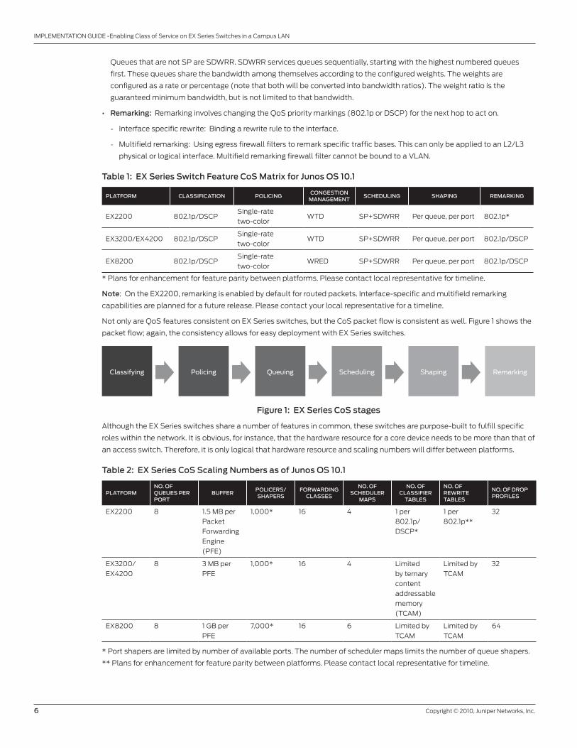
Not only are QoS features consistent on EX Series switches, but the CoS packet flow is consistent as well. Figure 1 shows the
packet flow; again, the consistency allows for easy deployment with EX Series switches.
Figure 1: EX Series CoS stages
Although the EX Series switches share a number of features in common, these switches are purpose-built to fulfill specific
roles within the network. It is obvious, for instance, that the hardware resource for a core device needs to be more than that of
an access switch. Therefore, it is only logical that hardware resource and scaling numbers will differ between platforms.
Table 2: EX Series CoS Scaling Numbers as of Junos OS 10.1
PLATFORMNO. OF QUEUES PER PORT
BUFFERPOLICERS/SHAPERS
FORWARDING CLASSES
NO. OF SCHEDULER
MAPS
NO. OF CLASSIFIER
TABLES
NO. OF REWRITE TABLES
NO. OF DROP PROFILES
EX2200 8 1.5 MB per
Packet
Forwarding
Engine
(PFE)
1,000* 16 4 1 per
802.1p/
DSCP*
1 per
802.1p**
32
EX3200/
EX4200
8 3 MB per
PFE
1,000* 16 4 Limited
by ternary
content
addressable
memory
(TCAM)
Limited by
TCAM
32
EX8200 8 1 GB per
PFE
7,000* 16 6 Limited by
TCAM
Limited by
TCAM
64
* Port shapers are limited by number of available ports. The number of scheduler maps limits the number of queue shapers.
** Plans for enhancement for feature parity between platforms. Please contact local representative for timeline.
Classifying Policing Queuing Scheduling Shaping Remarking
Page 7
Copyright © 2010, Juniper Networks, Inc. 7
IMPLEMENTATION GUIDE - Enabling Class of Service on EX Series Switches in a Campus LAN
Buffering
All EX Series switches support up to eight queues per port. The number of available queues gives network engineers the ability
to impose better traffic segmentation. Applications can be segregated into separate queues and no longer have to compete
with one another for buffer space and bandwidth. With separate QoS queues, Application A is now guaranteed a minimum
amount of bandwidth and is no longer subjected to long waits in the queue behind packets from other applications.
EX2200/EX3200/EX4200 Switches
Buffer sizes vary between platforms; for the buffer size on EX2200, EX3200, and EX4200 switches, all of which share the
same buffering architecture, please refer to Table 2. The buffer is divided between shared ingress, shared buffer pool, and
per-port dedicated buffers.
Figure 2: EX2200/EX3200/EX4200 PFE buffer allocation
Any dedicated queue buffer has equal access to the shared buffers. Through a CLI, the user can also dictate which queue has
access to the shared pool and change the buffer distribution between the shared pool and dedicated buffers.
• Exact: By default, any queue can use buffers from the shared pool (only packets marked with PLP low) if it runs out of its
guaranteed buffer allocation. The “exact” keyword disables the use of shared buffer on any particular queue.
IngressBu�ers
Po
rt 1
qu
eu
e 0
Po
rt 1
qu
eu
e 0
Po
rt 1
qu
eu
e 1
Po
rt 1
qu
eu
e 2
Po
rt 1
qu
eu
e 3
Po
rt 1
qu
eu
e 4
Po
rt 1
qu
eu
e 5
Po
rt 1
qu
eu
e 6
Po
rt 1
qu
eu
e 7
Po
rt 2
qu
eu
e 0
Po
rt 2
qu
eu
e 1
Po
rt 2
qu
eu
e 2
Po
rt X
qu
eu
e 5
Po
rt X
qu
eu
e 6
Po
rt X
qu
eu
e 7
Egress Bu�ers
Shared Pool
[edit class-of-service]schedulers { scheduler-name { buffer-size exact;}
• Shared buffer slider: The shared buffer slider gives users the flexibility to increase/decrease the per-port and shared
buffers. The default value is 100 percent. If the value is less than 100, then the shared pool is reduced and the remaining
buffers are redistributed evenly across the dedicated port buffers.
[edit class-of-service]shared-buffer percent percent;
Page 8
8 Copyright © 2010, Juniper Networks, Inc.
IMPLEMENTATION GUIDE -Enabling Class of Service on EX Series Switches in a Campus LAN
EX8200 Line
On the EX8200 line, there are buffers for the fabric and the egress port. The fabric interface has multiple ingress and egress
queues, which is similar to Virtual Output Queueing (VOQ). This helps ensure that a congested egress queue/port does
not affect other ports sending traffic, otherwise known as Head-of-Line Blocking (HOLB), and prevents the problem from
spreading while maximizing fabric throughput.
In addition to multiple supported fabric queues, the EX8200 line allows users to specify a fabric priority for the forwarding
class (either low or high). Latency-sensitive traffic should be mapped to the high priority fabric queue. The queue size and
transmit rate are optimized by the system and are not user configurable. However, a drop profile can be configured for the
high and low fabric queues for congestion management.
Because of the deep buffers on the EX8200, there is no shared buffer pool concept as with the other EX Series platforms.
While the buffer size of the queue can be allocated through configuration, there is some buffer elasticity between queues
within a port to allow a given queue to borrow some unused buffers from other queues.
Deploying CoS
CoS is only effective if it is deployed end-to-end. It serves no useful purpose if it is only configured in one or a few sections
of the network, and needs to be configured at every hop along the way from the source to the destination. In the next few
sections, this document will discuss a couple of CoS deployments for unicast and a mixture of unicast and multicast. This
document will also cover the why, where, and how for both access and core switches.
The majority of the CoS configuration is done under the class-of-service stanza of the Junos OS CLI. For specific CLI syntax or
additional sample configurations, please refer to the EX Series technical documents at www.juniper.net/customers/support/.
Trust and Untrust Domains
“Trust” and “untrust” are commonly used terms in a security context, but they can also be used in QoS, as they provide a clear
demarcation and make developing a QoS strategy easier. An edge device (such as an access switch or router connecting
to the Internet) resides between the trust and untrust boundary. These are the first and last entry points into and out of the
campus network. There is uncertainty about the QoS markings on packets coming from the untrusted domain, but once they
enter the campus LAN, network administrators have complete control and can manipulate packets so that they comply with
the established QoS strategy. Anything outside the campus LAN is considered untrusted; anything within the campus LAN is
considered trusted.
Page 9
Copyright © 2010, Juniper Networks, Inc. 9
IMPLEMENTATION GUIDE - Enabling Class of Service on EX Series Switches in a Campus LAN
Figure 3: CoS boundaries
Edge Devices
Since edge devices are the first and last entry points into and out of the campus LAN, the following recommended QoS
features should be enabled:
• Classification
• Congestion avoidance/management
• Scheduling
• Remarking
• Rate limiters
There are three different methods of classifying traffic; how it is classified depends on the traffic direction. If traffic is moving
from an untrusted to a trusted domain such as user-facing ports, then the recommended classifier is multifield. If traffic is
between trusted devices such as interswitch links, then the BA classifier can be used. Fixed classification is very stringent and
offers no granularity on how traffic should be classified, so it is seldom used. However, if it is used, it will typically be on an
edge device that is connected to an untrusted device.
Policing is an optional feature. If traffic rate limiting is required, then it should be done at the edge to help control the load
that will be entering or leaving the campus network.
Trusted
Trusted DomainUntrusted Domain
Untrusted Domain
Internet MPLSVPN
Page 10
10 Copyright © 2010, Juniper Networks, Inc.
IMPLEMENTATION GUIDE -Enabling Class of Service on EX Series Switches in a Campus LAN
It is recommended that some sort of congestion management capability be configured, as this helps prevent certain packets
from being buffered further or even dropped due to lack of buffer availability.
The EX Series switches support SP and SDWRR. While there is no limit to how many SP queues there can be, typically no
more than two are needed—one for control traffic and the other for latency-sensitive and jitter-sensitive traffic such as voice.
All other traffic can be serviced as SDWRR, which ensures fair bandwidth distribution between queues while reducing jitter
and offering lower maximum latency.
Lastly, remarking allows the next switch to act on the QoS marking that was established from the edge devices. Remarking
only needs to be applied on the edge links that are connecting to the core.
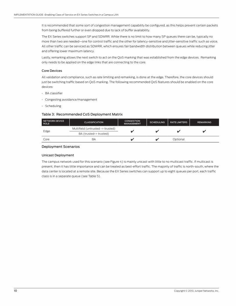
Core Devices
All validation and compliance, such as rate limiting and remarking, is done at the edge. Therefore, the core devices should
just be switching traffic based on QoS marking. The following recommended QoS features should be enabled on the core
devices:
• BA classifier
• Congesting avoidance/management
• Scheduling
Table 3: Recommended CoS Deployment Matrix
NETWORK DEVICE ROLE
CLASSIFICATIONCONGESTION
MANAGEMENTSCHEDULING RATE LIMITERS REMARKING
EdgeMultifield (untrusted -> trusted)
4 4 4 4BA (trusted-> trusted)
Core BA 4 4 Optional
Deployment Scenarios
Unicast Deployment
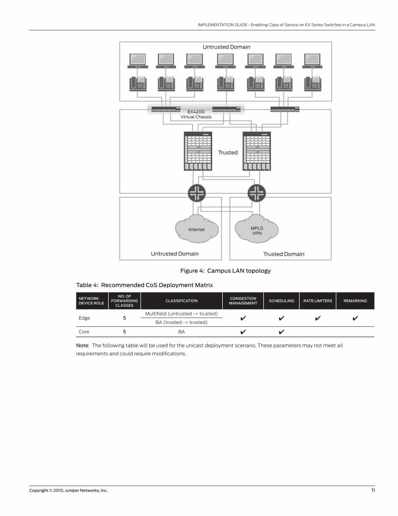
The campus network used for this scenario (see Figure 4) is mainly unicast with little to no multicast traffic. If multicast is
present, then it has little importance and can be treated as best-effort traffic. The majority of traffic is north-south, where the
data center is located at a remote site. Because the EX Series switches can support up to eight queues per port, each traffic
class is in a separate queue (see Table 5).
Page 11
Copyright © 2010, Juniper Networks, Inc. 11
IMPLEMENTATION GUIDE - Enabling Class of Service on EX Series Switches in a Campus LAN
Figure 4: Campus LAN topology
Table 4: Recommended CoS Deployment Matrix
NETWORK DEVICE ROLE
NO. OF FORWARDING
CLASSESCLASSIFICATION
CONGESTION MANAGEMENT
SCHEDULING RATE LIMITERS REMARKING
Edge 5Multifield (untrusted -> trusted)
4 4 4 4BA (trusted -> trusted)
Core 5 BA 4 4
Note: The following table will be used for the unicast deployment scenario. These parameters may not meet all
requirements and could require modifications.
Trusted
Trusted DomainUntrusted Domain
Untrusted Domain
Internet MPLSVPN
EX4200Virtual Chassis
Page 12
12 Copyright © 2010, Juniper Networks, Inc.
IMPLEMENTATION GUIDE -Enabling Class of Service on EX Series Switches in a Campus LAN
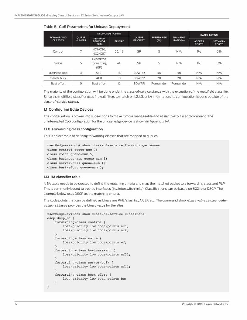
Table 5: CoS Parameters for Unicast Deployment
FORWARDING CLASSES
QUEUE NUMBER
DSCP CODE POINTS
QUEUE PRIORITY
BUFFER SIZE (%)
TRANSMIT RATE (%)
RATE LIMITING
PER-HOP BEHAVIOR
(PHB)BINARY ACCESS
PORTSNETWORK
PORTS
Control 7NC1/CS6,
NC2/CS756, 48 SP 5 N/A 1% 5%
Voice 5
Expedited
forwarding
(EF)
46 SP 5 N/A 1% 5%
Business app 3 AF21 18 SDWRR 40 40 N/A N/A
Server bulk 1 AF11 10 SDWRR 20 20 N/A N/A
Best effort 0 Best effort 0 SDWRR Remainder Remainder N/A N/A
The majority of the configuration will be done under the class-of-service stanza with the exception of the multifield classifier.
Since the multifield classifier uses firewall filters to match on L2, L3, or L4 information, its configuration is done outside of the
class-of-service stanza.
1.1 Configuring Edge Devices
The configuration is broken into subsections to make it more manageable and easier to explain and comment. The
uninterrupted CoS configuration for the unicast edge device is shown in Appendix 1-A.
1.1.0 Forwarding class configuration
This is an example of defining forwarding classes that are mapped to queues.
user@edge-switch# show class-of-service forwarding-classesclass control queue-num 7;class voice queue-num 5;class business-app queue-num 3;class server-bulk queue-num 1;class best-effort queue-num 0;
1.1.1 BA classifier table
A BA table needs to be created to define the matching criteria and map the matched packet to a forwarding class and PLP.
This is commonly bound to trusted interfaces (i.e., interswitch links). Classifications can be based on 802.1p or DSCP. The
example below uses DSCP as the matching criteria.
The code points that can be defined as binary are PHB/alias, i.e., AF, EF, etc. The command show class-of-service code-
point-aliases provides the binary value for the alias.
user@edge-switch# show class-of-service classifiers dscp dscp_ba { forwarding-class control { loss-priority low code-points nc1; loss-priority low code-points nc2; } forwarding-class voice { loss-priority low code-points ef; } forwarding-class business-app { loss-priority low code-points af21; } forwarding-class server-bulk { loss-priority low code-points af11; } forwarding-class best-effort { loss-priority low code-points be; }}
Page 13
Copyright © 2010, Juniper Networks, Inc. 13
IMPLEMENTATION GUIDE - Enabling Class of Service on EX Series Switches in a Campus LAN
1.1.2 Multifield classifier
Multifield classifier is one of the few CoS configurations done outside of the class-of-service stanza. Multifield uses a firewall
filter to match on L2, L3, and/or L4 information in order to assign the traffic to a forwarding class and PLP. It is common to
use multifield classifier on devices that are bordering on untrusted boundaries, such as end user traffic.
In the example below, there are four terms:
• Term 1 (voice-mf): If the source address is 172.20.32.0/24 or 146.217.32.0/24, it will be classified as voice traffic.
• Term 2 (business-app-mf): Any traffic being sent to 172.16.21.0/24 will be classified as a business application.
• Term 3 (server-bulk-mf): Any traffic being sent to 172.16.20.0/24 will be classified as server bulk.
• Term 4 (default): Any traffic not matched by the previous terms is considered best effort.
user@edge-switch# show firewall family ethernet-switching { filter mf-cos-classifier { term voice-mf { from { source-address { 172.20.32.0/24; 146.217.32.0/24; } } then { forwarding-class voice; loss-priority low; } } term business-app-mf { from { destination-address { 172.16.21.0/24; } } then { forwarding-class business-app; loss-priority low; } } term server-bulk-mf { from { destination-address { 172.16.20.0/24; } } then { forwarding-class server-bulk; loss-priority low; } } term default { then { forwarding-class best-effort; loss-priority low; } } }}
Page 14
14 Copyright © 2010, Juniper Networks, Inc.
IMPLEMENTATION GUIDE -Enabling Class of Service on EX Series Switches in a Campus LAN
1.1.3 Drop profile
A drop profile allows users to define a drop level (fill level) for a queue to proactively drop packets before the queue is
completely filled. When that level is reached on the EX2200, EX3200, or EX4200 switches, any packets marked with “PLP
high” are prevented from entering the queue (i.e., they are discarded). In this example, the fill level is set at 80%.
user@edge-switch# show class-of-service drop-profiles 80-full { fill-level 80;}
1.1.4 Schedulers
Buffer size, queue priority (SP or SDWRR), transmit rate, drop profile, and queue shaper are all defined within the scheduler
profile.
For queues configured as SP (priority high), it is recommended that a small percentage of buffers be reserved. Transmit rate
is not permitted because this queue will always be serviced when there is a packet in the queue. Due to the intrinsic behavior
of SP queues, they can potentially consume all of the bandwidth and starve the other queues. Therefore, it is recommended
that shaping be configured to prevent such an event. For more information on policing and shaping configurations, please
refer to the EX Series switch technical documentation at www.juniper.net/customers/support/.
Voice traffic should not be buffered over a long period of time since that will increase latency and jitter; instead the goal is to
drop the packet. Therefore the buffer size for the voice queue should be configured with an “exact” keyword, which prevents
any excess packets from being buffered into the shared pool, limiting the available buffer to what is allocated.
For other queues configured as SDWRR (priority low), buffer sizes can vary based on application load and requirements. It
is common to match the values for both transmit rate and buffer size. An alternative method of calculating the transmit
rate percentage is subtracting the buffer size percentage from 100. The logic is similar to the SP—if the queue has a higher
transmit rate, it will require fewer buffers; if the queue has a lower transmit rate, then it will require more buffers.
Note: Juniper recommends configuring SDWRR as a percentage, which provides an easier bandwidth ratio conversion.
user@edge-switch# show class-of-service schedulers control-network-sched { shaping-rate percent 5; buffer-size percent 5; priority strict-high; drop-profile-map loss-priority high protocol any drop-profile 80-full;}control-user-sched { shaping-rate percent 1; buffer-size percent 5; priority strict-high; drop-profile-map loss-priority high protocol any drop-profile 80-full;}voice-network-sched { shaping-rate percent 5; buffer-size percent 5 exact; priority strict-high;}voice-user-sched { shaping-rate percent 1; buffer-size percent 5 exact; priority strict-high;}business-sched { transmit-rate percent 60;
Page 15
Copyright © 2010, Juniper Networks, Inc. 15
IMPLEMENTATION GUIDE - Enabling Class of Service on EX Series Switches in a Campus LAN
buffer-size percent 60; priority low;}server-sched { transmit-rate percent 30; buffer-size percent 30; priority low;}be-sched { transmit-rate remainder; buffer-size remainder; priority low;}
1.1.5 Scheduler map
Scheduler map is a profile that binds schedulers to a forwarding class (queue). In this example, two scheduler map profiles
are created, one to apply on the user-facing ports (access-port-sched) and the other to apply on the networking facing ports
(network-port-sched).
user@edge-switch# show class-of-service scheduler-maps access-port-sched { forwarding-class control scheduler control-user-sched; forwarding-class voice scheduler voice-user-sched; forwarding-class business-app scheduler business-sched; forwarding-class server-bulk scheduler server-sched; forwarding-class best-effort scheduler be-sched;}network-port-sched { forwarding-class control scheduler control-network-sched; forwarding-class voice scheduler voice-network-sched; forwarding-class business-app scheduler business-sched; forwarding-class server-bulk scheduler server-sched; forwarding-class best-effort scheduler be-sched;}
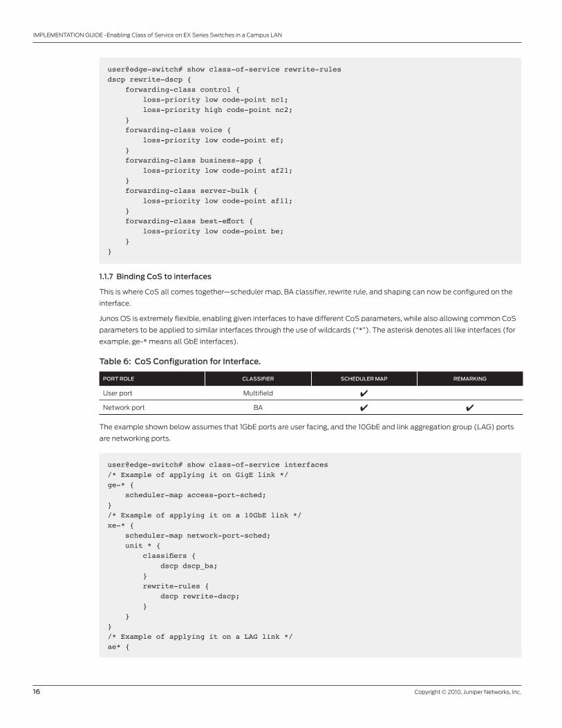
1.1.6 Rewrite rule table
The rewrite rule table provides a reference point between forwarding class and the QoS priority value. Based on the
forwarding class and rewrite rule table, the packet will be remarked with a new QoS marking prior to exiting the switch. The
new QoS priority value allows the next-hop device to match and treat the packet accordingly. A rewrite rule table can be
created for 802.1p or DSCP, or for both. Code points can either be in binary format or PHB (alias).
To enable remarking, the rewrite table has to be bound to the interface under the class-of-service stanza, or an egress
multifield remarking must be applied to an interface (covered in the next section).
Page 16
16 Copyright © 2010, Juniper Networks, Inc.
IMPLEMENTATION GUIDE -Enabling Class of Service on EX Series Switches in a Campus LAN
user@edge-switch# show class-of-service rewrite-rulesdscp rewrite-dscp { forwarding-class control { loss-priority low code-point nc1; loss-priority high code-point nc2; } forwarding-class voice { loss-priority low code-point ef; } forwarding-class business-app { loss-priority low code-point af21; } forwarding-class server-bulk { loss-priority low code-point af11; } forwarding-class best-effort { loss-priority low code-point be; }}
1.1.7 Binding CoS to interfaces
This is where CoS all comes together—scheduler map, BA classifier, rewrite rule, and shaping can now be configured on the
interface.
Junos OS is extremely flexible, enabling given interfaces to have different CoS parameters, while also allowing common CoS
parameters to be applied to similar interfaces through the use of wildcards (“*”). The asterisk denotes all like interfaces (for
example, ge-* means all GbE interfaces).
Table 6: CoS Configuration for Interface.
PORT ROLE CLASSIFIER SCHEDULER MAP REMARKING
User port Multifield 4
Network port BA 4 4
The example shown below assumes that 1GbE ports are user facing, and the 10GbE and link aggregation group (LAG) ports
are networking ports.
user@edge-switch# show class-of-service interfaces /* Example of applying it on GigE link */ge-* { scheduler-map access-port-sched;}/* Example of applying it on a 10GbE link */xe-* { scheduler-map network-port-sched; unit * { classifiers { dscp dscp_ba; } rewrite-rules { dscp rewrite-dscp; } }}/* Example of applying it on a LAG link */ae* {
Page 17
Copyright © 2010, Juniper Networks, Inc. 17
IMPLEMENTATION GUIDE - Enabling Class of Service on EX Series Switches in a Campus LAN
scheduler-map network-port-sched; unit * { classifiers { dscp dscp_ba; } rewrite-rules { dscp rewrite-dscp; } }}
1.1.8 Binding multifield classifier to interface
The multifield classifier needs to be bound to the interface in order for it to work. Since the multifield classifier is a firewall filter,
this function is done outside the class-of-service stanza. The multifield classifier needs to be configured as an input filter.
If the same multifield classifier is being applied to multiple ports, interface range or apply groups can be used for simplicity
and ease of configuration. Both of these methods allow like configurations to be applied to a set of interfaces. For more
information on interface range or apply groups, please refer to the EX Series technical documentation at www.juniper.net/
customers/support/.
user@edge-switch# show interfaces /* Example of applying a MF to a interface-range */interface-range user-ports { member “ge-0/0/[0-47]”; unit 0 { family ethernet-switching { filter { input mf-cos-classifier; } } }}/* Example of applying a MF to a specific interface */ge-0/0/0 { unit 0 { family ethernet-switching { filter { input mf-cos-classifier; } } } }
Note: If the same multifield classifier or rewrite is being used on multiple ports, it should be applied on VLAN vs. ports to
reduce TCAM utilization.
Page 18
18 Copyright © 2010, Juniper Networks, Inc.
IMPLEMENTATION GUIDE -Enabling Class of Service on EX Series Switches in a Campus LAN
/* Example of applying a MF classifier to a VLAN */user@edge-switch# show vlans user { vlan-id 100; filter { input mf-cos-classifier; }}voice { vlan-id 200; filter { input mf-cos-classifier; }}
1.2 Configuring core devices
One of the great advantages of running a single operating system across multiple devices is the ability to apply the exact
same configuration across platforms. The following CoS configuration can be copied from the edge device and run on the
core device.
• Forwarding class
• BA classifier
For the other CoS configuration, minor tweaks (covered later in this document) will be required. Again, similar to the edge
device section, this configuration is broken into subsections. For uninterrupted CoS configuration for the unicast core device,
please refer to Appendix 1-B.
1.2.0 Drop profile
This example uses interpolate WRED and creates multiple reference points. When a packet arrives at the egress queue, it is
given a random number and plotted against the reference points. Based on the place where it falls, the packet will either be
allowed into the queue or dropped.
Based on the example below, if the current buffer capacity (fill level) is at 50%, there is a 20% chance the packet will be
dropped. The EX8200 switches allow up to 32 pairs of fill level and drop probability. Drop profile is not just limited to PLP
high; a drop profile can also be created for PLP low.
user@core-switch# show class-of-service drop-profiles WRED-1 { interpolate { fill-level [ 0 50 75 85 90 100 ]; drop-probability [ 0 20 40 75 90 100 ]; }}
1.2.1 Schedulers
More often than not, the scheduler configuration is the same as the edge device. In some cases, however, minor tweaks may
be required.
Note: For the EX8200 switches, a scheduler is required for every queue that is being used on the port. Any queue that does
not have a scheduler will not be serviced.
Page 19
Copyright © 2010, Juniper Networks, Inc. 19
IMPLEMENTATION GUIDE - Enabling Class of Service on EX Series Switches in a Campus LAN
user@core-switch# show class-of-service schedulers control-sched { buffer-size percent 5; priority strict-high; drop-profile-map loss-priority high protocol any drop-profile WRED-1;}voice-sched { buffer-size percent 5; priority strict-high;}business-sched { transmit-rate percent 60; buffer-size percent 60; priority low;}server-sched { transmit-rate percent 30; buffer-size percent 30; priority low;}be-sched { transmit-rate remainder; buffer-size remainder; priority low;}
1.2.2 Scheduler map profile
Creating a scheduler map profile is no different than the one shown in the Configuring Edge Device subsection 1.1.5.
1.2.3 Binding CoS to interfaces
The CLI is the same as shown in Configuring Edge Device subsection 1.1.7. The only difference is applying it to the appropriate
interfaces, either 10GbE, LAG, or GbE interfaces.
Unicast/Multicast Deployment
In this scenario, the campus LAN has a mix of unicast and multicast traffic. Assume that users are sending voice and data
traffic and receiving voice, data, and video. There are two types of video being received, one that is latency sensitive (i.e., real-
time interactive) and one that is not latency sensitive (i.e., multimedia streaming).
Page 20
20 Copyright © 2010, Juniper Networks, Inc.
IMPLEMENTATION GUIDE -Enabling Class of Service on EX Series Switches in a Campus LAN
Figure 5: Unicast/multicast topology
Table 7: Recommended CoS Deployment Matrix
NETWORK DEVICE ROLE
NO. OF FORWARDING
CLASSESCLASSIFICATION
CONGESTION MANAGEMENT
SCHEDULING RATE LIMITERS REMARKING
Edge 6Multifield (untrusted -> trusted)
4 4 4 4Multifield (trusted -> trusted)
Core 6Multifield (untrusted -> trusted)
4 4Multifield (trusted -> trusted)
Note: The following table will be used for the unicast and multicast deployment scenarios. These parameters may not meet
all requirements and could require modification.
Trusted
Trusted DomainUntrusted Domain
Untrusted Domain
Untrusted
Internet MPLSVPN
EX4200Virtual Chassis
Page 21
Copyright © 2010, Juniper Networks, Inc. 21
IMPLEMENTATION GUIDE - Enabling Class of Service on EX Series Switches in a Campus LAN
Table 8: CoS Parameters for Unicast/Multicast Deployment
FORWARDING CLASSES
QUEUE NUMBER
DSCP CODE POINTS
QUEUE PRIORITY
BUFFER SIZE (%)
TRANSMIT RATE (%)
RATE LIMITER
PHB BINARY ACCESS PORTS
NETWORK PORTS
Control7
NC1/CS6,
NC2/CS756, 48 SP 5 N/A 1% 5%
Multicast control
Voice 6 EF 46 SP 5 N/A 1% 5%
Video live 5 CS4 32 SDWRR 10 10 N/A N/A
Video streaming 4 AF31 26 SDWRR 10 10 N/A N/A
Business app 3 AF21 18 SDWRR 40 40 N/A N/A
Server bulk 2 AF11 10 SDWRR 20 20 N/A N/A
Multicast best
effort *1 N/A N/A SDWRR 5 5 N/A N/A
Best effort 0 Best effort 0 SDWRR Remainder Remainder N/A N/A
* This is only specific to the EX8200 line; see section 2.1.0 for further details. The access devices do not require multicast best effort forwarding class to be configured.
From this point on, this document will focus on features not covered in the previous sections. If a specific section is not
mentioned, it can be safely assumed that the configuration is the same as described in the previous section, with the
exception of the CoS parameters which are based on Table 7. Although the drop profile for the edge or core devices were
not outlined in Table 7, the drop profiles created in Unicast Deployment, sections 1.1.3 and 1.2.0 respectively, can be used as a
good reference point.
For uninterrupted unicast/multicast core CoS configuration, please refer to Appendix 2.
2.1 Configuration of core devices
In Figure 5, the production servers are locally connected to the campus LAN network. One can argue about how to treat these
servers—trusted or untrusted. Typically, the production servers are under application/server administrator control and are
therefore treated as untrusted devices with a multifield classifier being used. However, for simplicity’s sake, this document
will treat production servers as trusted devices and apply a BA classification on ports connected to them.
2.1.0 Multicast on EX8200 line switches
The CoS configuration for multicast on the EX8200 line is different from that on the other Junos OS platforms due to
the EX8200-PFE (Packet Forwarding Engine) design. Each EX8200-PFE includes up to eight separate multicast queues
that collectively aggregate all of the broadcast, multicast, and unknown multicast traffic prior to being replicated. Once
replicated, the broadcast, multicast, and/or unknown unicast traffic is merged back into the corresponding unicast queue
where it can be scheduled along with the unicast traffic. By default, all broadcast, multicast, and unknown unicast traffic is
serviced out of Queue 2.
The difference between EX8200 switches and other Junos OS platforms is the binding point for classification and the
scheduler map for multicast traffic. On other Junos OS platforms, the classifier and scheduler map that are bound to the
interface (as shown in section 1.1.7) apply to both unicast and multicast traffic. Because of the architecture of the EX8200-
PFE, a new object, multi destination, was introduced to the class-of-service stanza to allow multicast classification based on
DSCP or the IP precedence classifier for routed multicast traffic. The multi destination also allows the network engineer to
move broadcast, switched multicast, and unknown unicast traffic to any queue other than the default Queue 2, and to define
the buffer size for the multicast queues through scheduler map.
Note: Classification on switched multicast traffic is under investigation.
Page 22
22 Copyright © 2010, Juniper Networks, Inc.
IMPLEMENTATION GUIDE -Enabling Class of Service on EX Series Switches in a Campus LAN
Multicast configuration only pertains to the EX8200 switches and is global. This means that all EX8200-PFEs will inherit the
configuration.
class-of-service { multi-destination { scheduler-map scheduler-map-name; family { ethernet { broadcast queue-number; } inet { classifier { dscp classifier-name; inet-precedence classifier-name; } } } }}
• The “scheduler map” allows the user to bind the scheduler-map profile for the multicast queue.
• The “ethernet broadcast” allows the user to specify the queue (forwarding class) for unknown unicast, broadcast, and
multicast traffic that is bridged by the device.
• The “inet classifier” allows the user to bind BA classifier for multicast traffic that is routed by the device. Only one type of
classifier is allowed, either DSCP or inet-precedence.
2.1.1 Configuring classifier for multicast traffic
Configuring the classifier is done through the standard Junos OS CLI syntax. Remember that the classifier for multicast is only
applicable to multicast traffic that is being routed.
user@core-switch# show class-of-service classifiers dscp mcast_ba { forwarding-class mcast-control { loss-priority low code-points [ cs6 cs7 ]; } forwarding-class video-live { loss-priority low code-points cs4; } forwarding-class video-streaming { loss-priority low code-points af31; }
}
Page 23
Copyright © 2010, Juniper Networks, Inc. 23
IMPLEMENTATION GUIDE - Enabling Class of Service on EX Series Switches in a Campus LAN
2.1.2 Configuring the scheduler profile for multicast queue
Configuring the scheduler profile is done through the standard Junos OS CLI syntax. The only parameter allowed for multicast
queue is buffer size—queue priority, transmit rate, and drop profile are not permitted.
user@core-switch# show class-of-service schedulers mcast-control-sched { buffer-size percent 10;}mcast-video-sched { buffer-size percent 35;}mcast-streaming-sched { buffer-size percent 35;}mcast-be-sched { buffer-size percent 20;
}
2.1.3 Configuring the scheduler map for the multicast queue
Similar to the scheduler profile, scheduler map configuration is done through the standard Junos OS CLI syntax.
user@core-switch# show class-of-service scheduler-maps mcast-sched { forwarding-class mcast-control scheduler mcast-control-sched; forwarding-class video-live scheduler mcast-video-sched; forwarding-class video-streaming scheduler mcast-streaming-sched; forwarding-class mcast-be scheduler mcast-be-sched;}
2.1.4 Binding the classifier and scheduler map, and moving the default queue for broadcast, L2 multicast, and
unknown unicast to a different queue
Juniper recommends that unicast and multicast be kept in separate queues. If there is a broadcast or unknown unicast storm,
then unicast traffic will not be affected.
multi-destination { scheduler-map mcast-sched; family { ethernet { broadcast mcast-be; } inet { classifier { dscp mcast_ba; } } }}
Page 24
24 Copyright © 2010, Juniper Networks, Inc.
IMPLEMENTATION GUIDE -Enabling Class of Service on EX Series Switches in a Campus LAN
2.1.5 Scheduler and scheduler map
As stated earlier, once the multicast traffic is replicated, it gets merged back with the unicast traffic to the corresponding
queues. Hence, a scheduler is still required for every queue. Since there are seven queues in this example, there should be
seven scheduler profiles.
user@core-switch# show class-of-service schedulers control-sched { buffer-size percent 5; priority strict-high; drop-profile-map loss-priority high protocol any drop-profile WRED-1;}voice-sched { buffer-size percent 5; priority strict-high;}video-sched { transmit-rate percent 10; buffer-size percent 10; priority low;}streaming-sched { transmit-rate percent 10; buffer-size percent 10; priority low;}business-sched { transmit-rate percent 40; buffer-size percent 40; priority low;}server-sched { transmit-rate percent 20; buffer-size percent 20; priority low;}mcast-sched { transmit-rate percent 5; buffer-size percent 5; priority low;}be-sched { transmit-rate remainder; buffer-size remainder; priority low;}user@core-switch# show class-of-service scheduler-maps network-port-sched { forwarding-class control scheduler nc-sched; forwarding-class voice scheduler voice-sched; forwarding-class video-live scheduler video-sched; forwarding-class video-streaming scheduler streaming-sched; forwarding-class business-app scheduler business-sched; forwarding-class server-bulk scheduler server-sched; forwarding-class mcast-be scheduler mcast-sched; forwarding-class best-effort scheduler be-sched;
}
Page 25
Copyright © 2010, Juniper Networks, Inc. 25
IMPLEMENTATION GUIDE - Enabling Class of Service on EX Series Switches in a Campus LAN
Although not shown, the next step is binding the network-port-sched scheduler map profile to the appropriate interfaces, as
well as any BA classifier for the unicast traffic.
Multifield Classifier for Multicast Traffic
One issue not discussed in previous sections is how to classify multicast traffic with multifield classifier. The only caveat
in using multifield classifier for multicast traffic is that, in addition to the forwarding class and loss priority in the action
statement, the keyword “cos-precedence high” needs to be added. This keyword is hidden and will not be required with Junos
OS 10.2 and beyond.
Multifield classifier can be bound to either Layer 2 or Layer 3 ports, although it will only classify multicast traffic that is to be
routed by the system.
The following example uses multifield classifier on multicast traffic based on group address. The multicast groups
225.1.1.0/24 and 225.1.2.0/24 will be classified as video live and video streaming, respectively.
user@core-switch# show firewall family inet { filter multicast_filter { term video-live-mf { from { destination-address { 225.1.1.0/24; } } then { count video-live; loss-priority low; forwarding-class video-live; cos-precedence high; } } term video-streaming-mf { from { destination-address { 225.1.2.0/24; } } then { count video-streaming; loss-priority low; forwarding-class video-streaming; cos-precedence high; } } term accept-all { then { count accept-all; accept; } }
}
The next step is to apply the multifield classifier as an input firewall filter to the required interface or VLAN.
Page 26
26 Copyright © 2010, Juniper Networks, Inc.
IMPLEMENTATION GUIDE -Enabling Class of Service on EX Series Switches in a Campus LAN
CoS Validation
The “show class-of-service sub-command” can be used to validate CoS configurations from the Junos OS operational mode.
Some of the available commands include:
classifier Show mapping of code point to forwarding class/loss priority drop-profile Show interpolated data points of named drop profile
interface Show mapping of CoS objects to interfaces rewrite-rule Show mapping of forwarding class/loss priority to code point scheduler-map Show mapping of forwarding classes to schedulers
The “show class-of-service interface interface-name” command provides a good summary of CoS configuration for the
port.
Use “show interface queue interface-name” to view queue statistics and validate that traffic is being forwarded out of the
configured queue.
The following command is only applicable to EX8200 line switches. To view CoS statistics for multicast traffic, use the
following command:
show pfe statistics traffic multicast fpc pfe-number
The PFE numbering starts at zero for the lowest slot number and proceeds from left to right. On the EX8200-8XS 10GbE
line card, there are four PFEs with two 10GbE ports per PFE. On the EX8200-48T/F line cards, there are two PFEs with 24
GbE ports per PFE.
Summary
Juniper Networks offers a pragmatic approach for simplifying the campus network. Running the Junos operating system on
EX Series Ethernet Switches provides consistent management and operations. In addition, the EX Series switches’ non-
blocking architecture offers wire-rate performance for both IPv4 and IPv6 (unicast and multicast) traffic. This simplifies the
network by reducing the campus LAN architecture from three to two tiers. Along with consistent and feature rich CoS, the EX
Series platforms can support the high-performance enterprise and ensure the prioritization of business critical applications
during times of traffic congestion, as well as meet the latency and jitter requirements of specialized types of traffic.
References
RFC4594, Guidelines for DiffServ Service Classes, August 2006
RFC 3246, An Expedited Forwarding PHB (Per-Hop Behavior), March 2002
Page 27
Copyright © 2010, Juniper Networks, Inc. 27
IMPLEMENTATION GUIDE - Enabling Class of Service on EX Series Switches in a Campus LAN
Appendix 1-A: Unicast Edge Device Configuration
user@edge-switch# show firewall family ethernet-switching { filter mf-cos-classifier { term voice-mf { from { source-address { 172.20.32.0/24; 146.217.32.0/24; } } then { forwarding-class voice; loss-priority low; } } term business-app-mf { from { destination-address { 172.16.21.0/24; } } then { forwarding-class business-app; loss-priority low; } } term server-bulk-mf { from { destination-address { 172.16.20.0/24; } } then { forwarding-class server-bulk; loss-priority low; } } term default { then { forwarding-class best-effort; loss-priority low; } } }}user@edge-switch# show class-of-service classifiers { dscp dscp_ba { forwarding-class control { loss-priority low code-points nc1; loss-priority high code-points nc2; } forwarding-class voice { loss-priority low code-points ef; } forwarding-class business-app {
Page 28
28 Copyright © 2010, Juniper Networks, Inc.
IMPLEMENTATION GUIDE -Enabling Class of Service on EX Series Switches in a Campus LAN
loss-priority low code-points af21; } forwarding-class server-bulk { loss-priority low code-points af11; } forwarding-class best-effort { loss-priority low code-points be; } }}drop-profiles { 80-full { fill-level 80; }} forwarding-classes { class control queue-num 7; class voice queue-num 5; class business-app queue-num 3; class server-bulk queue-num 1; class best-effort queue-num 0;}interfaces { ge-* { scheduler-map access-port-sched; } ae* { scheduler-map network-port-sched; unit 0 { classifiers { dscp dscp_ba; } rewrite-rules { dscp rewrite-dscp; } } }} rewrite-rules { dscp rewrite-dscp { forwarding-class control { loss-priority low code-point nc1; loss-priority high code-point nc2; } forwarding-class voice { loss-priority low code-point ef; } forwarding-class business-app { loss-priority low code-point af21; } forwarding-class server-bulk { loss-priority low code-point af11; } forwarding-class best-effort { loss-priority low code-point be; } }}
Page 29
Copyright © 2010, Juniper Networks, Inc. 29
IMPLEMENTATION GUIDE - Enabling Class of Service on EX Series Switches in a Campus LAN
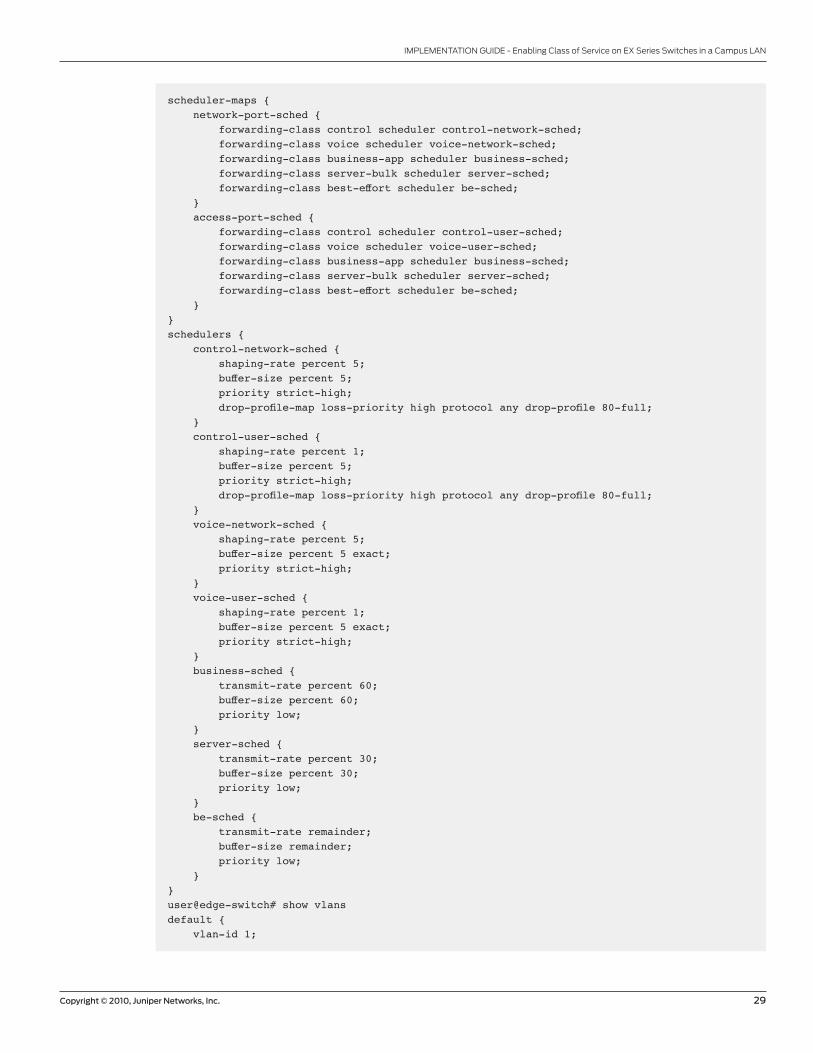
scheduler-maps { network-port-sched { forwarding-class control scheduler control-network-sched; forwarding-class voice scheduler voice-network-sched; forwarding-class business-app scheduler business-sched; forwarding-class server-bulk scheduler server-sched; forwarding-class best-effort scheduler be-sched; } access-port-sched { forwarding-class control scheduler control-user-sched; forwarding-class voice scheduler voice-user-sched; forwarding-class business-app scheduler business-sched; forwarding-class server-bulk scheduler server-sched; forwarding-class best-effort scheduler be-sched; }}schedulers { control-network-sched { shaping-rate percent 5; buffer-size percent 5; priority strict-high; drop-profile-map loss-priority high protocol any drop-profile 80-full; } control-user-sched { shaping-rate percent 1; buffer-size percent 5; priority strict-high; drop-profile-map loss-priority high protocol any drop-profile 80-full; } voice-network-sched { shaping-rate percent 5; buffer-size percent 5 exact; priority strict-high; } voice-user-sched { shaping-rate percent 1; buffer-size percent 5 exact; priority strict-high; } business-sched { transmit-rate percent 60; buffer-size percent 60; priority low; } server-sched { transmit-rate percent 30; buffer-size percent 30; priority low; } be-sched { transmit-rate remainder; buffer-size remainder; priority low; }}user@edge-switch# show vlans default { vlan-id 1;
Page 30
30 Copyright © 2010, Juniper Networks, Inc.
IMPLEMENTATION GUIDE -Enabling Class of Service on EX Series Switches in a Campus LAN
}user { vlan-id 100;input mf-cos-classifier; }}voice { vlan-id 200; filter { input mf-cos-classifier; }}
Page 31
Copyright © 2010, Juniper Networks, Inc. 31
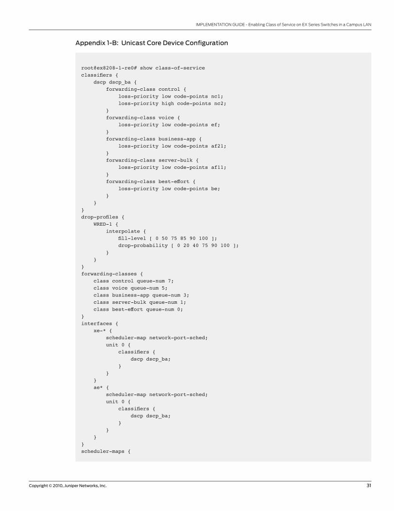
IMPLEMENTATION GUIDE - Enabling Class of Service on EX Series Switches in a Campus LAN
Appendix 1-B: Unicast Core Device Configuration
root@ex8208-1-re0# show class-of-service classifiers { dscp dscp_ba { forwarding-class control { loss-priority low code-points nc1; loss-priority high code-points nc2; } forwarding-class voice { loss-priority low code-points ef; } forwarding-class business-app { loss-priority low code-points af21; } forwarding-class server-bulk { loss-priority low code-points af11; } forwarding-class best-effort { loss-priority low code-points be; } }}drop-profiles { WRED-1 { interpolate { fill-level [ 0 50 75 85 90 100 ]; drop-probability [ 0 20 40 75 90 100 ]; } }}forwarding-classes { class control queue-num 7; class voice queue-num 5; class business-app queue-num 3; class server-bulk queue-num 1; class best-effort queue-num 0;}interfaces { xe-* { scheduler-map network-port-sched; unit 0 { classifiers { dscp dscp_ba; } } } ae* { scheduler-map network-port-sched; unit 0 { classifiers { dscp dscp_ba; } } }}scheduler-maps {
Page 32
32 Copyright © 2010, Juniper Networks, Inc.
IMPLEMENTATION GUIDE -Enabling Class of Service on EX Series Switches in a Campus LAN
network-port-sched { forwarding-class control scheduler control-sched; forwarding-class voice scheduler voice-sched; forwarding-class business-app scheduler business-sched; forwarding-class best-effort scheduler be-sched; }}schedulers { control-sched { buffer-size percent 5; priority strict-high; drop-profile-map loss-priority high protocol any drop-profile WRED-1; } voice-sched { buffer-size percent 5; priority strict-high; } business-sched { transmit-rate percent 60; buffer-size percent 60; priority low; } server-sched { transmit-rate percent 30; buffer-size percent 30; priority low; } be-sched { transmit-rate remainder; buffer-size remainder; priority low; }}
Page 33
Copyright © 2010, Juniper Networks, Inc. 33
IMPLEMENTATION GUIDE - Enabling Class of Service on EX Series Switches in a Campus LAN
Appendix 2: Unicast/Multicast Core Device Configuration
user@core-switch# show class-of-service classifiers { dscp dscp_ba { forwarding-class control { loss-priority low code-points cs6; loss-priority high code-points cs7; } forwarding-class voice { loss-priority low code-points ef; } forwarding-class business-app { loss-priority low code-points af21; } forwarding-class server-bulk { loss-priority low code-points af11; } forwarding-class best-effort { loss-priority low code-points be; } } dscp mcast_ba { forwarding-class mcast-control { loss-priority low code-points [ cs6 cs7 ]; } forwarding-class video-live { loss-priority low code-points cs4; } forwarding-class video-streaming { loss-priority low code-points af31; } }}drop-profiles { WRED-1 { interpolate { fill-level [ 0 50 75 85 90 100 ]; drop-probability [ 0 20 40 75 90 100 ]; } }}forwarding-classes { class control queue-num 7; class mcast-control queue-num 7; class voice queue-num 6; class video-live queue-num 5; class video-streaming queue-num 4; class business-app queue-num 3; class server-bulk queue-num 2; class mcast-be queue-num 1; class best-effort queue-num 0;}interfaces { ge-* { scheduler-map network-port-sched; unit 0 { classifiers {
Page 34
34 Copyright © 2010, Juniper Networks, Inc.
IMPLEMENTATION GUIDE -Enabling Class of Service on EX Series Switches in a Campus LAN
dscp dscp_ba; } } } xe-* { scheduler-map network-port-sched; unit 0 { classifiers { dscp dscp_ba; } } } ae* { scheduler-map network-port-sched; unit 0 { classifiers { dscp dscp_ba; } } }}scheduler-maps { network-port-sched { forwarding-class control scheduler control-sched; forwarding-class voice scheduler voice-sched; forwarding-class video-live scheduler video-sched; forwarding-class video-streaming scheduler streaming-sched; forwarding-class business-app scheduler business-sched; forwarding-class server-bulk scheduler server-sched; forwarding-class mcast-be scheduler mcast-sched; forwarding-class best-effort scheduler be-sched; } mcast-sched { forwarding-class mcast-control scheduler mcast-control-sched; forwarding-class video-live scheduler mcast-video-sched; forwarding-class video-streaming scheduler mcast-streaming-sched; forwarding-class mcast-be scheduler mcast-be-sched; }}schedulers { control-sched { buffer-size percent 5; priority strict-high; drop-profile-map loss-priority high protocol any drop-profile WRED-1; } voice-sched { buffer-size percent 5; priority strict-high; } video-sched { transmit-rate percent 10; buffer-size percent 10; priority low; } streaming-sched { transmit-rate percent 10; buffer-size percent 10; priority low;
Page 35
Copyright © 2010, Juniper Networks, Inc. 35
IMPLEMENTATION GUIDE - Enabling Class of Service on EX Series Switches in a Campus LAN
} business-sched { transmit-rate percent 40; buffer-size percent 40; priority low; } server-sched { transmit-rate percent 20; buffer-size percent 20; priority low; } mcast-sched { transmit-rate percent 5; buffer-size percent 5; priority low; } be-sched { transmit-rate remainder; buffer-size remainder; priority low; } mcast-control-sched { buffer-size percent 10; } mcast-video-sched { buffer-size percent 35; } mcast-streaming-sched { buffer-size percent 35; } mcast-be-sched { buffer-size percent 20; } }multi-destination { scheduler-map mcast-sched; family { ethernet { broadcast mcast-be; } inet { classifier { dscp mcast_ba; } } }}
Page 36
8010073-001-EN June 2010
Copyright 2010 Juniper Networks, Inc. All rights reserved. Juniper Networks, the Juniper Networks logo, Junos, NetScreen, and ScreenOS are registered trademarks of Juniper Networks, Inc. in the United States and other countries. All other trademarks, service marks, registered marks, or registered service marks are the property of their respective owners. Juniper Networks assumes no responsibility for any inaccuracies in this document. Juniper Networks reserves the right to change, modify, transfer, or otherwise revise this publication without notice.
EMEA Headquarters
Juniper Networks Ireland
Airside Business Park
Swords, County Dublin, Ireland
Phone: 35.31.8903.600
EMEA Sales: 00800.4586.4737
Fax: 35.31.8903.601
APAC Headquarters
Juniper Networks (Hong Kong)
26/F, Cityplaza One
1111 King’s Road
Taikoo Shing, Hong Kong
Phone: 852.2332.3636
Fax: 852.2574.7803
Corporate and Sales Headquarters
Juniper Networks, Inc.
1194 North Mathilda Avenue
Sunnyvale, CA 94089 USA
Phone: 888.JUNIPER (888.586.4737)
or 408.745.2000
Fax: 408.745.2100
www.juniper.net
To purchase Juniper Networks solutions,
please contact your Juniper Networks
representative at 1-866-298-6428 or
authorized reseller.
Printed on recycled paper
36 Copyright © 2010, Juniper Networks, Inc.
IMPLEMENTATION GUIDE - Enabling Class of Service on EX Series Switches in a Campus LAN
About Juniper Networks
Juniper Networks, Inc. is the leader in high-performance networking. Juniper offers a high-performance network infrastructure
that creates a responsive and trusted environment for accelerating the deployment of services and applications over a single
network. This fuels high-performance businesses. Additional information can be found at www.juniper.net.