Enabling Hydrogen Embrittlement Modeling of Structural Steels Brian Somerday Sandia National Laboratories June 11, 2008 Project ID # PDP11 This presentation does not contain any proprietary, confidential, or otherwise restricted information Sandia is a multiprogram laboratory operated by Sandia Corporation, a Lockheed Martin Company, for the United States Department of Energy under contract DE-AC04-94AL85000
Transcript
Enabling Hydrogen EmbrittlementModeling of Structural Steels
Brian SomerdaySandia National Laboratories
June 11, 2008
Project ID # PDP11This presentation does not contain any proprietary, confidential, or otherwise restricted information
Sandia is a multiprogram laboratory operated by Sandia Corporation, a Lockheed Martin Company, for the United States Department of Energy under contract DE-AC04-94AL85000
Overview
• Project start date Jan. 2007• Project end date Sept. 2015• Percent complete 15%
• Barriers addressed– High Capital Cost and
Hydrogen Embrittlement of Pipelines
– Storage Tank Materials and Costs
• Total project funding (through FY08)– DOE share: $384K
• FY07 Funding: $184K• FY08 Funding: $200K
Budget
• DOE Pipeline Working Group– Sandia National Lab– Oak Ridge National Lab– Savannah River National Lab– CTC– NIST– Industrial gas companies– ASME
Partners
Timeline Barriers & Targets
Objectives
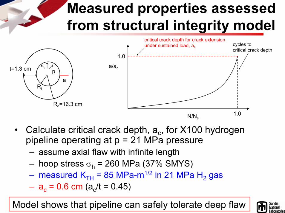
• Enable application of structural integrity models to steel hydrogen pipelines– Models can demonstrate that hydrogen embrittlement can be
accommodated and pipeline safety margins can be quantified
• Enable development of micromechanics models of hydrogen embrittlement in pipeline steels– Micromechanics models are essential for understanding the
fundamentals of hydrogen transport and embrittlement in steels
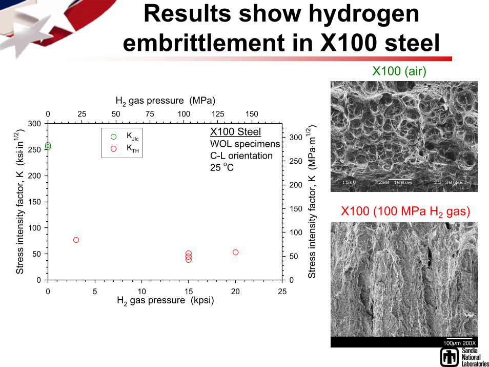
• Measure cracking kinetics and thresholds of X100 steel under static loading in hydrogen gas pressures from 7 to 140 MPa (FY08 Q1; complete)
• Measure fatigue crack propagation rates of X100 steel in hydrogen gas over the pressure range 7 to 140 MPa (FY08 Q3; in progress)
Milestones
Approach
• Measure properties of pipeline steels in high-pressure H2 gas using fracture mechanics methods– Thresholds for sustained-load cracking– Fatigue crack growth rates under cyclic loading
• Assess suitability of steels by using measured properties as inputs into structural integrity models– Materials are qualified for service if pipeline meets performance
critieria, e.g., number of allowable pressure cycles
• Identify and measure fundamental parameters in mechanistic models of hydrogen embrittlement
Materials testing motivated by design method
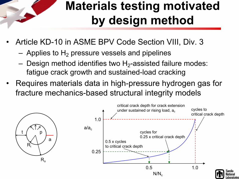
• Article KD-10 in ASME BPV Code Section VIII, Div. 3– Applies to H2 pressure vessels and pipelines– Design method identifies two H2-assisted failure modes:
fatigue crack growth and sustained-load cracking• Requires materials data in high-pressure hydrogen gas for
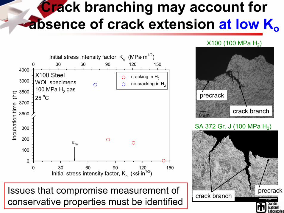
Issues that compromise measurement of conservative properties must be identified
X100 (100 MPa H2)
precrack
crack branch10 μm
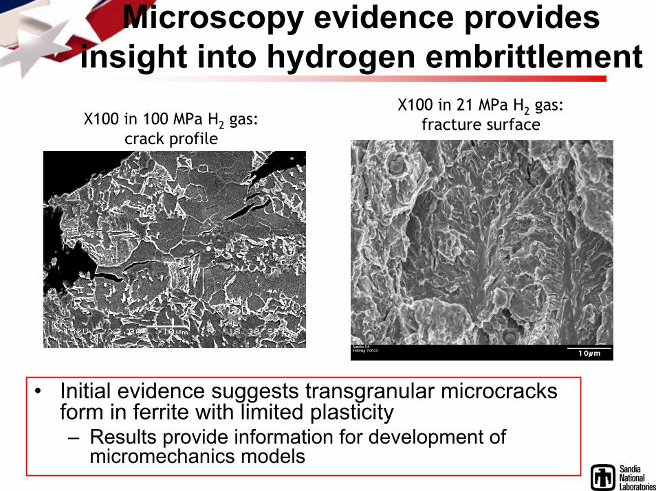
Microscopy evidence provides insight into hydrogen embrittlementX100 in 100 MPa H2 gas:
crack profile
X100 in 21 MPa H2 gas:fracture surface
• Initial evidence suggests transgranular microcracksform in ferrite with limited plasticity– Results provide information for development of
micromechanics models
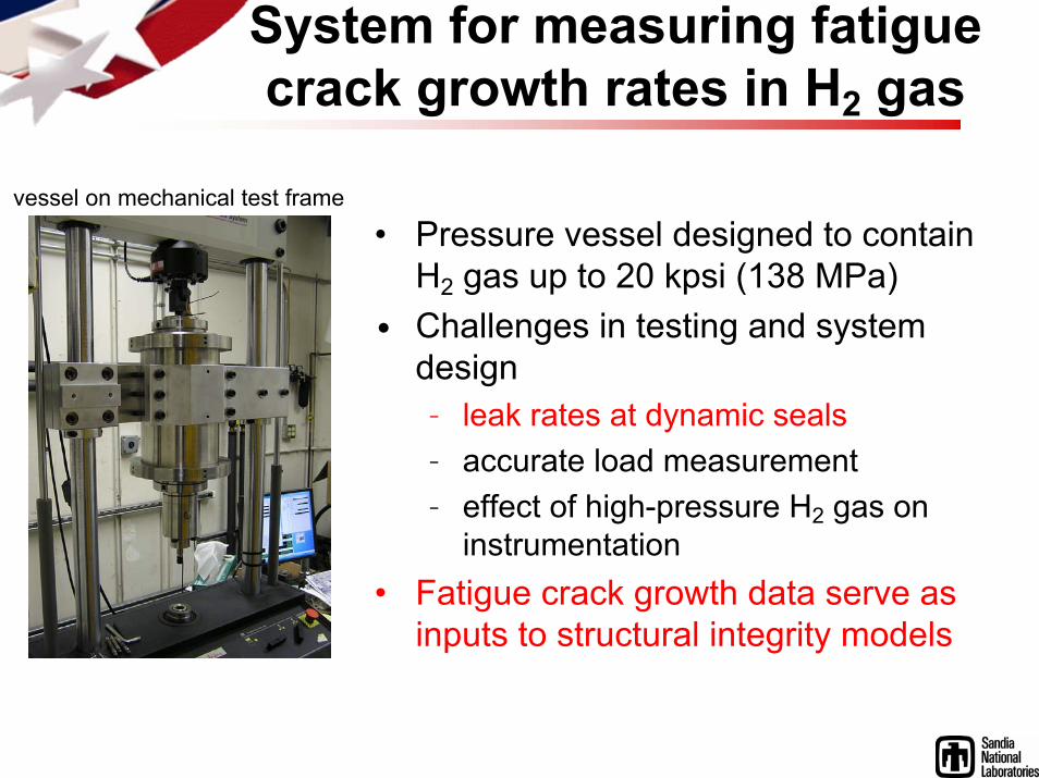
System for measuring fatigue crack growth rates in H2 gas
• Pressure vessel designed to contain H2 gas up to 20 kpsi (138 MPa)
• Challenges in testing and system design– leak rates at dynamic seals– accurate load measurement– effect of high-pressure H2 gas on
instrumentation• Fatigue crack growth data serve as
inputs to structural integrity models
vessel on mechanical test frame
Future Work
Remainder of FY08• Determine solution for leaks at sliding seals in system for
measuring fatigue crack growth rates in hydrogen gas• Measure fatigue crack growth rates of X100 in hydrogen gas
FY09• Emphasize testing of low-strength steels such as X42 and X52
− Includes base metal and welds− Measure fracture toughness, sustained-load cracking thresholds,
and fatigue crack growth rates in hydrogen gas
Summary
• Completed measurements of cracking thresholds for X100 steel as a function of H2 gas pressure– Structural integrity model shows that pipeline fabricated from X100
could tolerate deep flaws– Testing results demonstrate that procedures must be defined to
ensure conservative properties are measured
• Microscopy evidence suggests that hydrogen embrittlementproceeds by transgranular fracture across the ferrite phase– Such evidence provides important information for the development
of micromechanics models of hydrogen embrittlement