Page 1
Approved
Document ID 5316
Enbridge Line 6B MP 608
Marshall, MI Pipeline Release
Case No.: 15-1411-CE
Large Woody Debris Installation Plan
Supplement to Large Woody Debris Replacement Work Plan
Prepared for Michigan Department of Environmental Quality
Enbridge Energy, Limited Partnership
Submitted: June 15, 2016 Approved: July 25, 2016
(MDEQ Approval: July 21, 2016)
Page 2
Approved
ii
Table of Contents
1.0 INTRODUCTION ............................................................................................................... 1
2.0 LWD INSTALLATION APPROACH ................................................................................. 2
2.1 Ceresco Restoration Reach .................................................................................. 2
2.2 Mill Ponds (MP 14.25 – MP 15.00) ......................................................................... 4
2.3 MP 19.25 – Fort Custer Bridge (MP 20.10) ........................................................... 5
2.4 MP 25.40 L1 ............................................................................................................ 7
2.5 MP 32.00 – 35th Street Bridge (MP 36.50) ............................................................. 8
2.6 Delta Powerline Region (MP 36.50 – MP 37.00) ................................................... 9
3.0 ENGINEERING DETAILS ............................................................................................... 10
4.0 RESTORATION .............................................................................................................. 11
5.0 LWD NAVIGATION CONTROL PLAN ........................................................................... 12
6.0 PROPERTY ACCESS PLAN .......................................................................................... 12
7.0 SCHEDULE .................................................................................................................... 13
8.0 REFERENCES ................................................................................................................ 13
FIGURES
Figure 1 Ceresco Restoration Reach
Figure 2 Mill Ponds (MP 14.25 – MP 15.00)
Figure 3 MP 19.25 – Fort Custer Bridge (MP 20.10)
Figure 4 MP 25.40 L1
Figure 5 MP 32.00 to 35th Street Bridge (MP 36.50)
Figure 6 Delta Powerline Region (MP 36.50 – MP 37.00)
Page 3
Approved
iii
TABLES
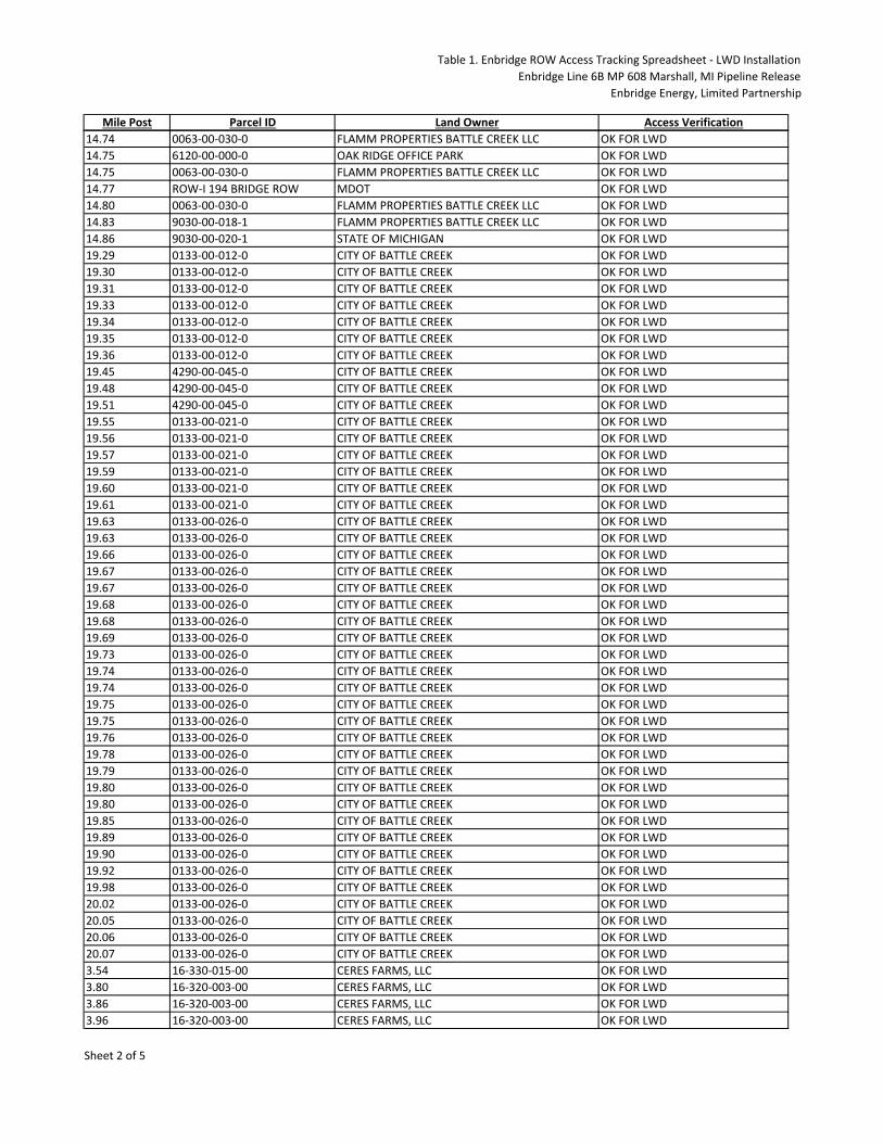
Table 1 Enbridge ROW Access Tracking Spreadsheet - LWD Installation
Table 2 Proposed LWD Installation Schedule
ATTACHMENTS
Attachment A MP 25.40 L1 Design
Attachment B Engineering Details
Attachment C Navigation Control Plan
Page 4
Approved
iv
LIST OF ACRONYMS
BAJ Bar Apex Jams Enbridge Enbridge Energy, Limited Partnership ft feet
LGP low ground pressure
LWD large woody debris
LWD Plan Large Woody Debris Installation Plan
LWD Replacement Work Plan Large Woody Debris Replacement Work Plan, submitted to MDEQ on June 2, 2016
MP Mile Post
RDB right descending bank
ROW Right of Way
Page 5
Approved
1
1.0 INTRODUCTION
This Large Woody Debris (LWD) Installation Plan (LWD Plan) serves as a Supplement to
the Large Woody Debris Replacement Work Plan, submitted to the Michigan Department of
Environmental Quality on June 2, 2016 (LWD Replacement Work Plan) (Enbridge, 2016)
and provides logistical details with respect to transport and installation of LWD, engineering
details to include fastening and placement of LWD structures, restoration, navigation control
and public safety, and property access along the Kalamazoo River.
Specifically, the purpose of this LWD Plan is to provide site-specific detail for work
conducted in each of the six river work segments consisting of the following information:
• Installation Approach includes figures outlining proposed structure types and
installation locations, equipment access routes, equipment and LWD staging areas,
available LWD pile locations where LWD will be retrieved from the banks, and boat
access locations for each of the six river work segments: Ceresco Restoration
Reach, Mill Ponds (Mile Post (MP) 14.25 to MP 15.00), MP 19.25 to Fort Custer
Bridge (MP 20.10), MP 25.40 L1, MP 32.00 to 35th Street Bridge (MP 36.50), and
Delta Powerline Region (MP 36.10 to MP 37.00).
• Engineering Details depicting plan view and cross-section views of the proposed
LWD structure types. The details will reference the structure location/position to the
approximate bankfull and baseflow elevations and will include typical depth
placements, anchor and fastening criteria, and angle orientation related to the river
bank. Additionally, the details will provide proposed cut/fill volumes where log burial
and bank excavation is performed.
Corresponding information consists of restoration considerations; a Navigation Control
Plan describing on-water traffic control and debris management, and associated worker
and public safety precautions for work within the Kalamazoo River; Property Access Plan
describing Enbridge Energy, Limited Partnership (Enbridge) right of way (ROW) activities
on notifying affected property owners and obtaining property access for staging,
structure installation and launch areas; and installation schedule.
Page 6
Approved
2
2.0 LWD INSTALLATION APPROACH
In an effort to gather information as the basis for development of installation methods, field
observations and planning activities were conducted as a collective effort between Enbridge
and the selected LWD Contractor from April 27 through and including June 9, 2016. The
primary focus of the planning activities was to:
• Review and field verify proposed LWD structure installation locations and adjust
locations based on actual riverbed and bank conditions,
• Assess LWD staging and access locations,
• Further refine engineering details for installation of structures, and
• Develop specific means and methods for safe and efficient transport of LWD in the
Kalamazoo River.
Based on information gathered during these efforts and consideration to minimize
disturbance to the river system, Enbridge has prepared Installation Approaches for each
river work segment presented herein. Amphibious equipment (i.e. boats, barges, and
amphibious excavator) have been utilized into the installation approaches to limit river
disturbance. The river work segments are presented in order of upstream to downstream
locations, but do not reflect the order in which they will be scheduled for installation. Please
refer to Section 7.0 for the proposed installation schedule.
Presently, a majority of the LWD to be used for installation of the proposed structures is
staged at Enbridge-owned property located at 16054 Division Drive, Marshall, Michigan.
LWD will be hauled from this primary staging location to the designated staging areas along
the Kalamazoo River.
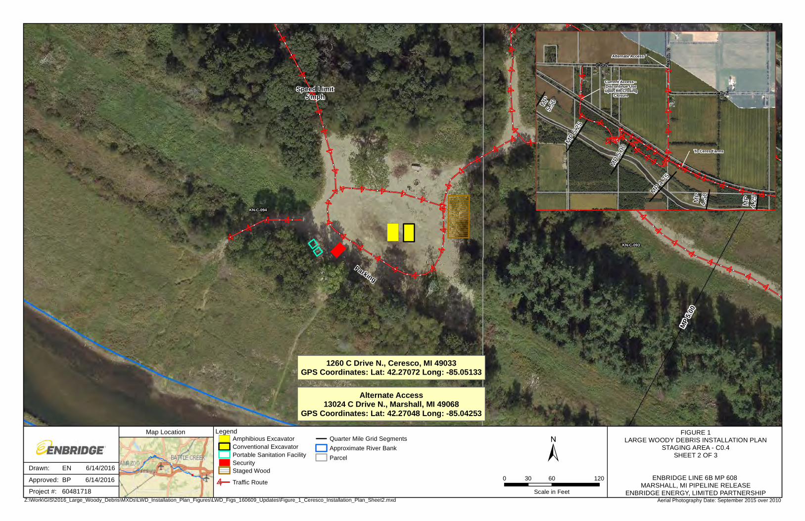
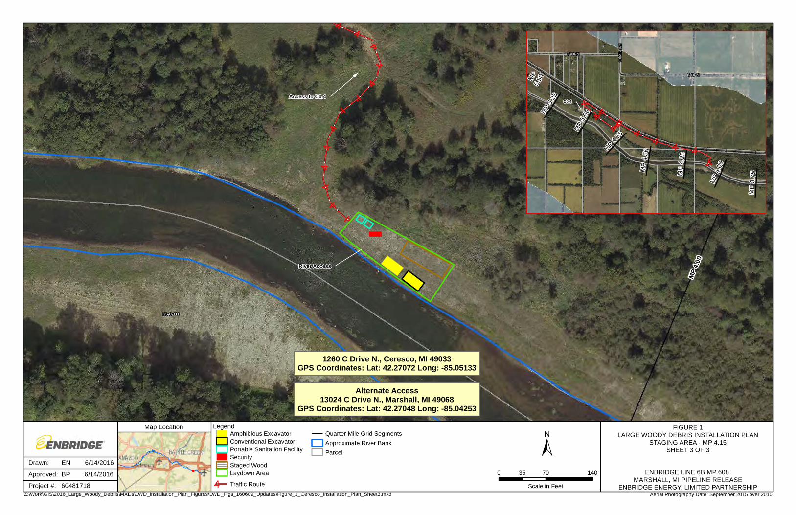
2.1 Ceresco Restoration Reach
A total of 16 structures are proposed for installation in the Ceresco Restoration Reach river
work segment to include: 2 Type 1A Log Vane, and 14 Type 1B Habitat Log structures.
LWD required to install these will be staged at two locations within the river work segment.
The staging areas consist of the former boat launch known as C0.4 located at approximately
MP 5.10 right descending bank (RDB) and an auxiliary staging area near MP 4.15 RDB.
The C0.4 and MP 4.15 RDB staging areas will be used for staging LWD and heavy
Page 7
Approved
3
equipment and as river entry points for heavy equipment. Boats used for navigation control,
LWD assistance, and other project-related needs will enter/exit the river at Saylor’s Landing
Boat Launch daily. Figure 1 depicts the locations of the proposed staging areas, installation
locations, and equipment travel routes; and details the proposed staging area layouts and
traffic patterns for access.
Enbridge and the LWD Contractor have developed the following preferred approach to
deliver and install LWD in the Ceresco Restoration Reach:
• Barge by Boat Method: At each staging area, a conventional excavator will load a
barge (approximately 10 feet (ft) by 40 ft) with LWD material. The amount of LWD
loaded onto the barge will depend on current water elevations. The loaded barge
can be towed/pushed by a boat to each structure install location where an
amphibious excavator will offload the barge and workers will complete installation.
Once the LWD materials are offloaded, the barge will be towed/pushed back to the
staging area via boat and the process repeated. A boat may also be used to haul
select LWD material.
Field conditions will govern the efficiency of mobilizing the barge with boats. If water levels
or other conditions will not allow for installation using the barge with boat method, Enbridge
and the LWD Contractor have prepared the following alternative methods:
• Timber Floating Method: At each staging area, a conventional excavator will be
used to load LWD material into the river. The LWD will be temporarily bundled
together on land, in the river, or a combination thereof, in a configuration that will
allow for the LWD to be towed to each structure install location where an amphibious
excavator will unbundle and workers will complete installation. A boat may also be
used to haul select LWD material.
• Barge by Equipment Method: A conventional excavator will load a barge with LWD
materials at the staging areas. The amount of LWD loaded onto the barge will be
based on current water elevations. The loaded barge can be towed/pushed by the
amphibious excavator or the 6x6 low ground pressure (LGP) amphibious vehicle to
each structure install location where an amphibious excavator will offload the barge
and workers will complete installation. Once the LWD materials are offloaded, the
Page 8
Approved
4
barge will be towed/pushed back to the staging area via boat and the process
repeated. A boat may also be used to haul select LWD material.
Structures will be installed in the Ceresco Restoration Reach of the Kalamazoo River
working upstream to downstream. Structure details and associated installation criteria are
further outlined in Section 3.0. A Navigation Control Plan has been developed for safe and
efficient work practices in the Kalamazoo River as further described in Section 5.0.
2.2 Mill Ponds (MP 14.25 – MP 15.00)
A total of 63 structures are proposed for installation in the Mill Ponds river work segment to
include: 42 Type 1B Habitat Log structures; 18 Type 2 Wooden Wing Deflector structures;
and, 3 Type 3 bar apex jams (BAJ) structures.
LWD will be staged at one staging location referenced to as C5 boat launch near MP 14.80
RDB in Battle Creek, Michigan. The staging area will be used for staging LWD and also
river entry points for heavy equipment. Boats used for navigation control, LWD assistance,
and other project-related needs will also enter/exit the river at C5 boat launch daily. Figure 2
depicts the location of the proposed staging area, installation locations, and equipment travel
routes; and details the proposed staging area layout and traffic patterns for access.
Enbridge and the LWD Contractor have developed the following preferred approach for
installation of structures in the Mill Ponds river work segment:
• Barge by Boat Method: At each staging area, a conventional excavator will load a
barge with LWD material. The amount of LWD loaded onto the barge will depend on
current water elevations. The loaded barge can be towed/pushed by a boat to each
structure install location where an amphibious excavator will offload the barge and
workers will complete installation. Once the LWD materials are offloaded, the barge
will be towed/pushed back to the staging area via boat and the process repeated. A
boat may also be used to haul select LWD material.
Field conditions will govern the efficiency of mobilizing the barge with boats. If water levels
or other conditions will not allow for installation using the barge with boat method, Enbridge
and the LWD Contractor have prepared the following alternative methods:
Page 9
Approved
5
• Timber Floating Method: At each staging area, a conventional excavator will be
used to load LWD material into the river. The LWD will be temporarily bundled
together on land, in the river, or a combination thereof, in a configuration that will
allow for the LWD to be towed to each structure install location where an amphibious
excavator will unbundle and workers will complete installation. A boat may also be
used to haul select LWD material.
• Barge by Equipment Method: A conventional excavator will load a barge with LWD
materials at the staging areas. The amount of LWD loaded onto the barge will be
based on current water elevations. The loaded barge can be towed/pushed by the
amphibious excavator or the 6x6 LGP amphibious vehicle to each structure install
location where an amphibious excavator will offload the barge and workers will
complete installation. Once the LWD materials are offloaded from the barge using
an amphibious excavator, the barge will be towed/pushed back to the staging area
via boat and the process repeated.
Structures will be installed in the Mill Ponds river work segment working upstream to
downstream. Structure details and associated installation criteria are further outlined in
Section 3.0. A Navigation Control Plan has been developed for safe and efficient work
practices in the Kalamazoo River as further described in Section 5.0.
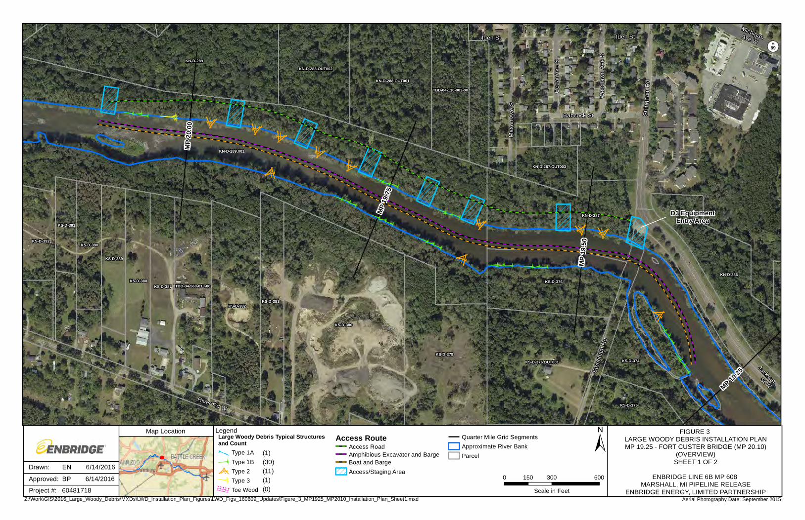
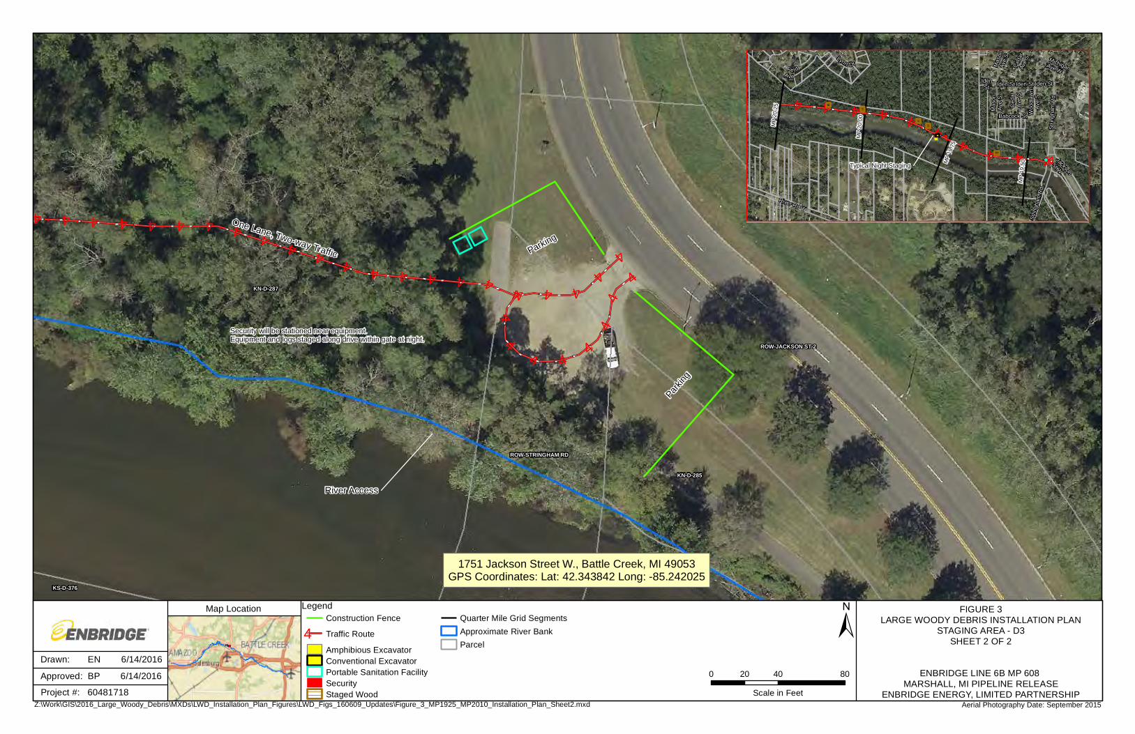
2.3 MP 19.25 – Fort Custer Bridge (MP 20.10)
A total of 43 structures are proposed for installation in MP 19.25 to Fort Custer Bridge
(MP 20.10) river work segment to include: 1 Type 1A Log Vane structure; 30 Type 1B
Habitat Log structures; 11 Type 2 Wooden Wing Deflector structures; and, 1 Type 3 BAJ
structure.
The staging areas selected within this river work segment are generally spread out along a
City of Battle Creek owned utility service road running parallel to the river on the north bank.
Along the service road, there are multiple open areas or “spurs” that extend both north and
south of the road. The river equipment and LWD material will be staged along these open
areas, and also along the service road shoulders. The service road point of beginning is
located along the tree line of the maintained Linear Park in Battle Creek, Michigan. Facilities
and light equipment storage may be staged just outside the service road area, within the
Linear Park area. Boats will launch daily from the D2 Boat launch located at Linear Park.
Page 10
Approved
6
Boat transport vehicles/trailers and some employee vehicles will also be parked at the D2
parking lot. The remaining vehicles will be parked within the service road area. The
amphibious excavator will enter/exit the river at D3 located near MP 19.45. Figure 3 depicts
locations of the proposed staging areas, installation locations, and equipment travel routes;
and details the proposed staging areas layout and traffic patterns for access.
Enbridge and the LWD Contractor have developed the following preferred approach to
installation of structures in the MP 19.25 to Fort Custer Bridge river work segment:
• Barge by Boat Method: At each staging area, a conventional excavator will load a
barge with LWD material. The amount of LWD loaded onto the barge will depend on
current water elevations. The loaded barge can be towed/pushed by a boat to each
structure install location where an amphibious excavator will offload the barge and
workers will complete installation. Once the LWD materials are offloaded, the barge
will be towed/pushed back to the staging area via boat and the process repeated. A
boat may also be used to haul select LWD material.
Field conditions will govern the efficiency of mobilizing the barge with boats. If water levels
or other conditions will not allow for installation using the barge with boat method, Enbridge
and the LWD Contractor have prepared the following alternative methods:
• Timber Floating Method: At each staging area, a conventional excavator will be
used to load LWD material into the river. The LWD will be temporarily bundled
together on land, in the river, or a combination thereof, in a configuration that will
allow for the LWD to be towed to each structure install location where an amphibious
excavator will unbundle and workers will complete installation. A boat may also be
used to haul select LWD material.
• Barge by Equipment Method: A conventional excavator will load a barge with LWD
materials at the staging areas. The amount of LWD loaded onto the barge will be
based on current water elevations. The loaded barge can be towed/pushed by the
amphibious excavator or the 6x6 LGP amphibious vehicle to each structure install
location where an amphibious excavator will offload the barge and workers will
complete installation. Once the LWD materials are offloaded from the barge using
an amphibious excavator, the barge will be towed/pushed back to the staging area
via boat and the process repeated.
Page 11
Approved
7
Structures will be installed in the MP 19.25 to Fort Custer Bridge river segment of the
Kalamazoo River working upstream to downstream. Structure details and associated
installation criteria are further outlined in Section 3.0. A Navigation Control Plan has been
developed for safe and efficient work practices in the Kalamazoo River as further described
in Section 5.0.
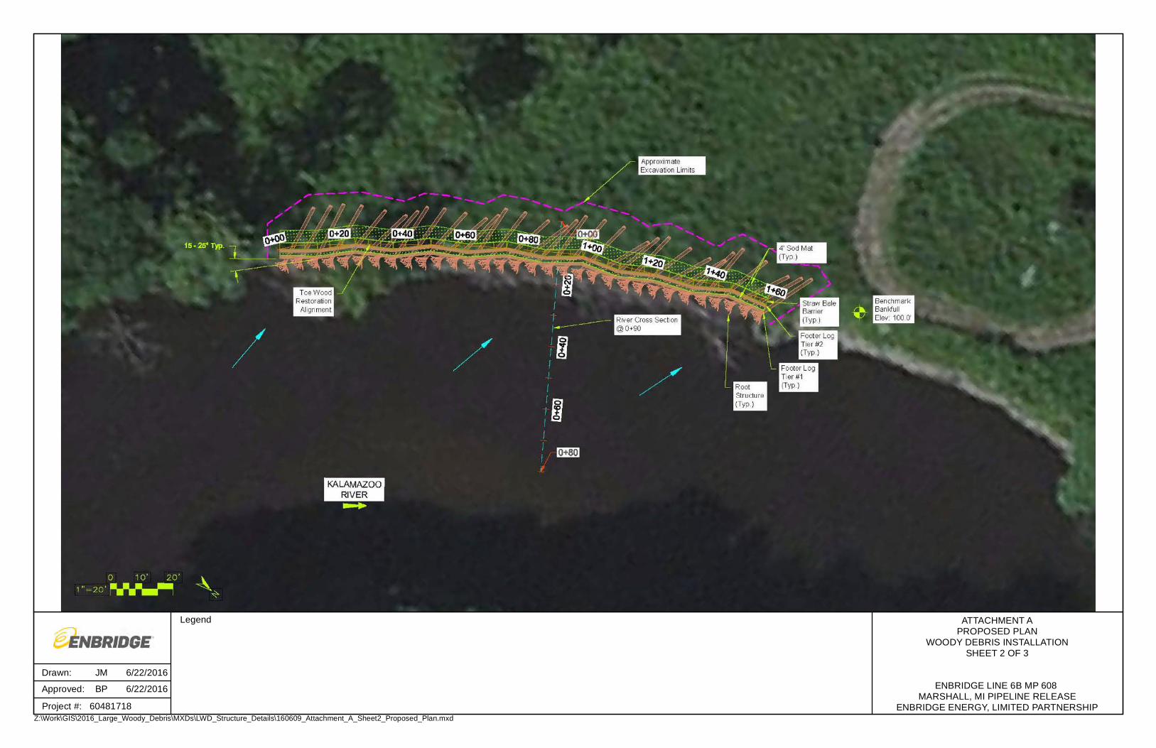
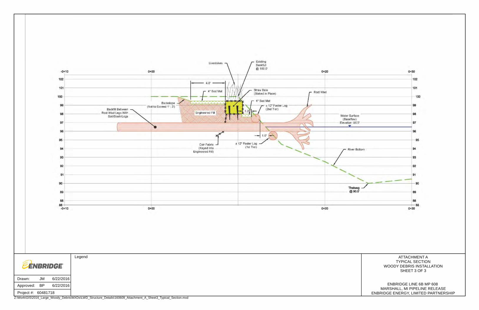
2.4 MP 25.40 L1
A toe wood installation is proposed for erosion control at the work site located at
MP 25.40L1 which was previously acknowledged during the Kalamazoo River Bank Erosion
Assessment. Based on field measurements, the bank height is approximately 3.5 ft above
the baseflow water surface, and the eroded section is approximately 160 ft in length. The
toe wood structure will extend along the eroded section of the bank and be constructed of
root wads, footer/header logs, slash, straw bales, and coir fabric. Live stakes will also be
incorporated into the structure. The toe wood design for MP 25.40L1 is further detailed in
Attachment A.
The majority of the work will occur on land, including delivery of LWD material which will be
imported to the project site, excavation activities, installation, and backfilling. The
excavation will be performed using a conventional excavator by positioning the excavator on
the overbank and excavating away from the channel. The excavated soil will be stockpiled
onsite for reuse as engineered fill, topsoil cover, and sod matting. The conventional
excavator will also be utilized to install the logs, root wads, and backfill. Boats will be utilized
at this worksite for navigation control and debris management purposes, however it is not
anticipated that LWD install work will occur through use of boats. Boats will enter/exit the
river at the Shady Bend boat launch located near MP 27.00 and downstream of the worksite.
Figure 4 depicts the location of the proposed staging area, installation locations, and
equipment travel routes; and details the proposed staging area layout and traffic patterns for
access.
A Navigation Control Plan has been developed for safe and efficient work practices in the
Kalamazoo River as further described in Section 5.0.
Page 12
Approved
8
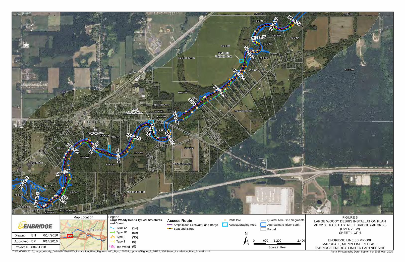
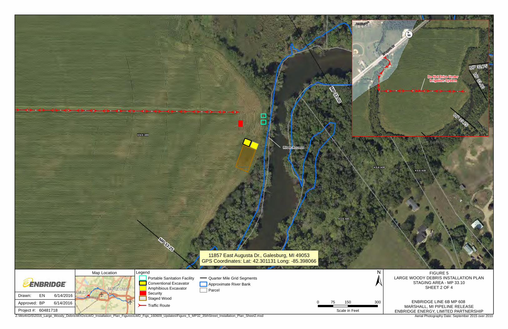
2.5 MP 32.00 – 35th Street Bridge (MP 36.50)
A total of 127 structures are proposed for installation in MP 32.00 to 35th Street Bridge river
segment to include: 14 Type 1A Log Vane structures; 69 Type 1B Habitat Log structures; 35
Type 2 Wooden Wing Deflector structures; and, 9 Type 3 BAJ structures. LWD will be
imported to the work segment and staged at the referenced staging areas. Additionally,
LWD piles located on the banks will be retrieved using an amphibious excavator and
transported using one of the methods outlined below to a staging area and/or directly to a
structure install location. Based on field observations, the LWD piles are located within
reach of the amphibious excavator positioned in the river. Locations of LWD piles are
identified on Figure 5.
Because this river work segment is lengthy in comparison to other river work segments,
three staging areas will be required to reduce the length and frequency of river travel. The
Michigan Avenue Bridge in Galesburg prevents upstream equipment travel from the lower
portions of the river segment. Therefore, two staging areas are located downstream and
one staging area will be located upstream of the Michigan Avenue Bridge.
Specifically, LWD staging locations that may be used are as follows: MP 33.10, E2.5 (Time
Out Lounge), and E3 (MP 35.11). The MP 33.10 staging area will be used for staging of
LWD and the launching point for the amphibious excavator installing structures between MP
32.00 and Michigan Avenue Bridge (MP 34.10). E2.5 will be used for staging of heavy
equipment, boats, and parking as needed. E3 will be used as both a staging area for LWD
and launching point for barges, boats, 6x6 LGP amphibious vehicle, and/or amphibious
excavator installing structures between Michigan Avenue Bridge (MP 34.10) and 35th Street
Bridge (MP 36.50). Figure 5 depicts the locations of the proposed staging areas, installation
locations, and equipment travel routes; and details the proposed staging area layouts and
traffic patterns for access.
Enbridge and the LWD Contractor have developed the following preferred approach to
installation of structures in the MP 32.00 to 35th Street Bridge river segment:
• Barge by Boat Method: At each staging area, a conventional excavator will load a
barge with LWD material. The amount of LWD loaded onto the barge will depend on
current water elevations. The loaded barge can be towed/pushed by a boat to each
structure install location where an amphibious excavator will offload the barge and
Page 13
Approved
9
workers will complete installation. Once the LWD materials are offloaded, the barge
will be towed/pushed back to the staging area via boat and the process repeated. A
boat may also be used to haul select LWD material.
Field conditions will govern the efficiency of mobilizing the barge with boats. If water levels
or other conditions will not allow for installation using the barge with boat method, Enbridge
and the LWD Contractor have prepared the following alternative methods:
• Timber Floating Method: At each staging area, a conventional excavator will be
used to load LWD material into the river. The LWD will be temporarily bundled
together on land, in the river, or a combination thereof, in a configuration that will
allow for the LWD to be towed to each structure install location where an amphibious
excavator will unbundle and workers will complete installation. A boat may also be
used to haul select LWD material.
• Barge by Equipment Method: A conventional excavator will load a barge with LWD
materials at the staging areas. The amount of LWD loaded onto the barge will be
based on current water elevations. The loaded barge can be towed/pushed by the
amphibious excavator or the 6x6 LGP amphibious vehicle to each structure install
location where an amphibious excavator will offload the barge and workers will
complete installation. Once the LWD materials are offloaded from the barge using
an amphibious excavator, the barge will be towed/pushed back to the staging area
via boat and the process repeated.
Structures will be installed in the MP 32.00 to 35th Street river segment of the Kalamazoo
River working upstream to downstream. Structure details and associated installation criteria
are further outlined in Section 3.0. A Navigation Control Plan has been developed for safe
and efficient work practices in the Kalamazoo River as further described in Section 5.0.
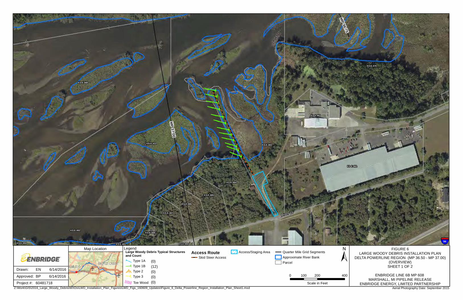
2.6 Delta Powerline Region (MP 36.50 – MP 37.00)
A total of 12 structures are proposed for installation in Delta Powerline Region (MP 36.50 to
MP 37.00) river segment to include 12 Type 1B Log Vane structures.
LWD required to install these structures will be staged along the Kalamazoo River at a single
staging location referenced as Delta Powerline. Delta Powerline will be used as both a
staging area for LWD and access point for heavy equipment needed to installed structures in
Page 14
Approved
10
the Delta Powerline Region river segment. The boat launch at E3 will be used as the launch
for safety and other support boats. Figure 6 depicts the location of the proposed staging
area, installation location, and equipment travel routes; and details the proposed staging
area layout and traffic patterns for access.
Enbridge and the LWD Contractor have developed the following preferred approach to
installation of structures in the Delta Powerline Region river segment:
• Overbank Delivery Method: At the staging area, a skid steer positioned on the
overbank will be used to haul LWD along the embankment into the Kalamazoo River
for installation.
If access to Delta Powerline is not granted, Enbridge and the LWD Contractor have
prepared the following alternative method:
• Timber Floating Method: At the E3 staging area, a conventional excavator will be
used to load LWD material into the river. The LWD will be temporarily bundled
together on land, in the river, or a combination thereof, in a configuration that will
allow for the LWD to be towed to each structure install location where an amphibious
excavator will unbundle and workers will complete installation. Root wads may need
to be detached from logs, if this method is required, to allow passage through the
relatively shallow Delta region. A boat may also be used to haul select LWD
material.
Structure details and associated installation criteria are further outlined in Section 3.0. A
Navigation Control Plan has been developed for safe and efficient work practices in the
Kalamazoo River as further described in Section 5.0.
Ancillary equipment located at staging areas described in Section 2.1 through and including
Section 2.6 above, may include, but is not limited to: tool trailers, support vehicles, skid
steers, crane, and equipment attachments.
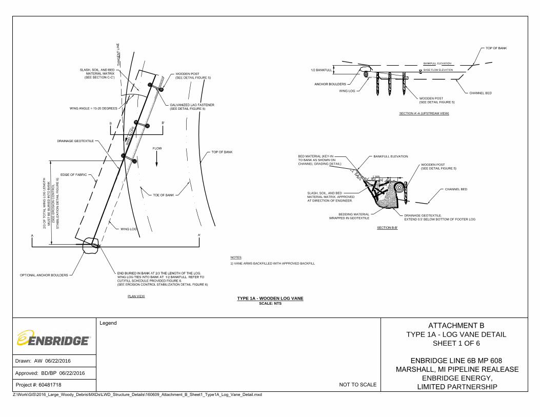
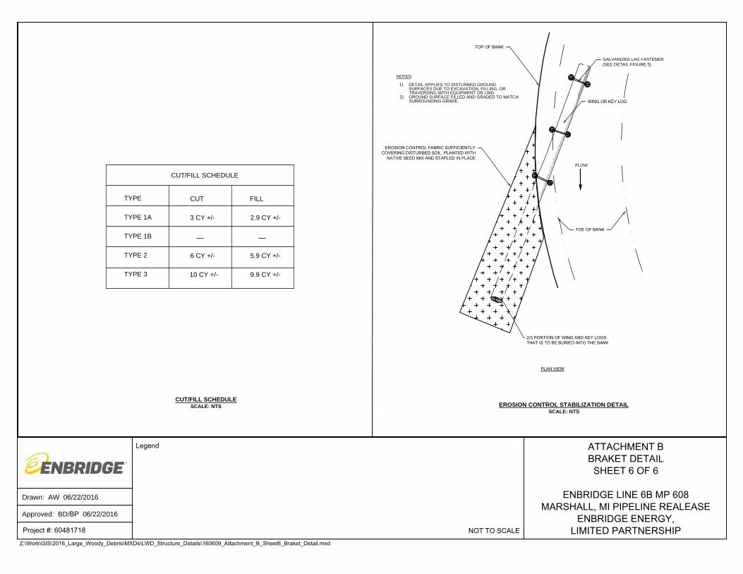
3.0 ENGINEERING DETAILS
Engineering details are provided in Attachment B of this LWD Installation Plan depicting plan
and cross-section views of the proposed LWD structure types (i.e., Type 1A, Type 1B,
Page 15
Approved
11
Type 2, and Type 3). The details reference the structure location/position to the
approximate bankfull and baseflow elevations and include typical depth placements, anchor
and fastening criteria, overall structure dimensions, and angle orientation related to the river
bank. The details also report proposed cut/fill volumes where log burial and bank excavation
is performed. Design details for toe the wood installation at MP 25.40 L1 are also included
in Attachment A. The details included in Attachment B of the LWD Replacement Work Plan
were considered general details showing the overall composition and extent of each
structure.
The in-water structures were designed with minimum protrusion lengths into the channel,
providing a relatively insignificant blockage to flow. The effect of accumulation of material
onto the structures has been incorporated into the design and based on the minimum
protrusion lengths, overly sized LWD will deflect away from the structures preventing
significant accumulations. Based on implementation of similar structures and research
studies, large accumulation of material is not anticipated.
Implementation of this LWD Installation Plan will rely on the experience of the LWD
Contractor to make informed decisions about structure installation at each specific install
location and within each river work segment. Therefore, Enbridge and the LWD Contractor
are prepared to make adjustments in the field to accommodate for changes in site conditions
as needed.
4.0 RESTORATION
Enbridge is prepared to conduct restoration activities where impacts of LWD installation
activities occur. Potential impacts requiring restoration may include the following:
• Overbank impacts at or near the staging and launch areas. Impacts will likely consist
of ground surface disturbance (i.e., tracking, scarifying) caused by equipment
trafficking,
• Overbank impacts caused by cutting/filling during installation of key logs,
• Overbank impacts caused by retrieval of LWD staged on banks, likely consisting of
scarifying the ground surface, and
• Overbank impacts caused by tracking equipment in and out of the river at the
designated staging areas.
Page 16
Approved
12
The majority of the impacts will be caused by excavation required to install the proposed
LWD structures. Careful consideration and care has been implemented into planning to
minimize excavation footprints and volumes. The proposed cut/fill volumes for structure
installations are designed to balance, meaning any material excavated from the overbank or
river channel will be reused as backfill within the structure excavation(s). Refer to the
Cut/Fill Schedule included in Attachment B for specific proposed volumes. The excavations
will be backfilled in controlled lifts, and the resulting surface of the excavation will be graded
to match the general surrounding grades. The exposed surface of the excavation will be
planted with a native seed mix and stabilized with erosion control fabric as shown on the
Typical Erosion Control Stabilization Detail shown on Attachment B. Other impacted areas
receiving this type of restoration may include bank disturbance caused by tracking
equipment and surface scarification caused by skidding LWD material across the overbank,
such as the areas of LWD retrieval from the banks.
It is Enbridge’s intent to minimize the potential introduction and/or spread of invasive
species. All equipment shall be cleaned and inspected prior to entry into the Kalamazoo
River.
5.0 LWD NAVIGATION CONTROL PLAN
Enbridge has developed procedures for navigation control and debris management on the
Kalamazoo River focused on ensuring worker and public safety during LWD structure
installation activities and during transport of LWD on the Kalamazoo River. The Navigation
Control Plan outlines equipment used for support and transport, control setup, monitoring,
and management. Refer to Attachment C for a copy of LWD Navigation Control Plan for
specific details.
6.0 PROPERTY ACCESS PLAN
Enbridge ROW has utilized an outreach system that involves contacting, via telephone
and/or face-to-face visit, each property owner that may be affected by the LWD Installation
project on the Kalamazoo River. Property owners have been identified that may be affected
by structure installation and stockpiled LWD removal activities, LWD and equipment staging
locations, and launch locations. Enbridge ROW maintains a tracking spreadsheet to log
Page 17
Approved
13
landowner contact activities. Refer to Table 1 for the access tracking spreadsheet which
includes: MP designation, affected parcels, property owners, and access verification status.
7.0 SCHEDULE
The proposed schedule for the LWD Installation Project assumes that the LWD Plan will be
approved by the end of June 2016. Public safety and predicted concentrations of public
recreation were the main factors in preparing the proposed schedule. The Ceresco
Restoration Reach and MP 32 to 35th Street Bridge river segments experience heavier public
use, especially during the summer months, in comparison to the Mill Ponds, MP 25.40 L1,
and MP 19.25 to Fort Custer Bridge river segments. Therefore, the schedule was prepared
to conduct work in Mill Ponds, MP 25.40 L1, and MP 19.25 to Fort Custer Bridge river
segments prior to the Labor Day Holiday, then work will focus on the remaining river work
segments during the fall season. The proposed schedule, provided as Table 2, assumes
river work will primarily be conducted Monday through Friday with select work conducted on
Saturdays (e.g., LWD delivery to staging areas, mobilization, and equipment set up).
Unexpected delays that may shift the proposed schedule, such as weather, are not
accounted for in this schedule. Conversely, efficiencies realized during installation could
reduce the forecasted work durations.
8.0 REFERENCES
Enbridge, 2016. Enbridge Energy, Limited Partnership Line 6B MP 608 Pipeline Release,
Marshall, Michigan; Large Woody Debris Replacement Work Plan, dated June 2, 2016.
Page 19
MP 4.
25
MP 3.50
MP 3.
75
MP 4.75
MP 5.
00
MP 4.
50
MP 4.
00
MP 5.25
KN-C-095
KN-C-093
KS-C-117
KN-C-092
KS-C-116
KS-C-115
KS-C-114
KN-C-091
KS-C-113
KS-C-112
KS-C-111
KS-C-114 KS-C-113ROW-A DRIVE-1
TBD-16-320-024-00 TBD-16-321-018-00TBD-16-321-018-01
TBD-16-321-003-00
TBD-16-291-009-00TBD-16-281-021-00
TBD-16-310-009-00
TBD-16-310-003-02
KN-C-089
KS-C-110
KN-C-090
KN-C-094
FIGURE 1LARGE WOODY DEBRIS INSTALLATION PLAN
CERESCO RESTORATION REACH(OVERVIEW)
SHEET 1 OF 3
ENBRIDGE LINE 6B MP 608 MARSHALL, MI PIPELINE RELEASE
ENBRIDGE ENERGY, LIMITED PARTNERSHIPAerial Photography Date: September 2015 over 2010
Map Location Legend
0 600 1,200300
Scale in Feet
±Drawn: EN 6/14/2016
Approved: BP 6/14/2016
Project #: 60481718Z:\Work\GIS\2016_Large_Woody_Debris\MXDs\LWD_Installation_Plan_Figures\LWD_Figs_160609_Updates\Figure_1_Ceresco_Installation_Plan_Sheet1.mxd
Large Woody Debris Typical Structures and Count
Type 1AType 1B Type 2Type 3
Access RouteAmphibious Excavator and BargeBoat and BargeAccess/Staging Area
Quarter Mile Grid SegmentsApproximate River BankParcel(2)
(14)(0)
(0)Toe Wood
(0)
MP 4.15Staging Area
C0.4STAGING AREA
Page 20
44
44
44
44
44
44
44
44
44
44
44
44
44
44
44
44
44
44
44
44
44
44
44
44
44
44
44
44
44
44
44
44
44
44
44
44
44
44
44
44
44
44
44
44
44
44
44
44
44
44
44
44
44
44
44
44
44
44
44
44
44
44
44
44
44
44
44
44
44
44
44
44
444
44
44
44
4 4 4
44
44
44
44
44
44
44
44
44
4
44
44
44
44
44
44
44
44
44
44
44
44
44
44
4 4 4 4
44
44
44
44
44
44
44
44
44
44
44
44
44
44
44
44
44
44
44
44
44
44
44
44
44
44
44
44
44
44
44
44
44
44
44
44
44
44
44
44444444444
44
44
44
44
44
44
44
44
44
44
44
44
44
44
44
44
44
44
44
44
44
44
44
44
44
44
44
44
44
44
44
´´
´´
´´
´´
´´
´´
´´
´´
´´
´´
´
´´
´´´´´´´´´´
´´
´´
´´
´´
´´
´´
´´
´´
´´
´´
´´
´´
´´
´´
´´
´´
´´
´´
´´
´´
´´
´´
´´
´´
´´
´´
´´
´´
´´
´´
´
44
44
44
´
´´
´´
44
4 4´
´ ´ ´
444444
44
44
44
4 4
44
4
´´´´´
´´
´´
´´
´ ´
´´
´
MP 5.
00
KN-C-093
KN-C-094
FIGURE 1LARGE WOODY DEBRIS INSTALLATION PLAN
STAGING AREA - C0.4SHEET 2 OF 3
ENBRIDGE LINE 6B MP 608 MARSHALL, MI PIPELINE RELEASE
ENBRIDGE ENERGY, LIMITED PARTNERSHIPAerial Photography Date: September 2015 over 2010
Map Location Legend
0 60 12030
Scale in Feet
±Drawn: EN 6/14/2016
Approved: BP 6/14/2016
Project #: 60481718Z:\Work\GIS\2016_Large_Woody_Debris\MXDs\LWD_Installation_Plan_Figures\LWD_Figs_160609_Updates\Figure_1_Ceresco_Installation_Plan_Sheet2.mxd
Amphibious ExcavatorConventional ExcavatorPortable Sanitation FacilitySecurityStaged Wood
4 Traffic Route
Quarter Mile Grid SegmentsApproximate River BankParcel
1260 C Drive N., Ceresco, MI 49033GPS Coordinates: Lat: 42.27072 Long: -85.05133
Alternate Access13024 C Drive N., Marshall, MI 49068
GPS Coordinates: Lat: 42.27048 Long: -85.04253
44
44
444
4
44
4 44
´´
´´
´´
´
´´
´ ´´
´
44
4
44
´´
´´
44
4
´
4
44
44
44
´´
´
´´
´
44
44 4 4 4
´´
´ ´ ´ ´
To Ceres Farms
Alternate Access
Current Access - Discontinue UseUpon RR Crosing
Closure
MP
4.25
MP
5.50
MP
4.50
MP 4.75
MP
5.00
MP
5.25
C Dr N
13 M
ile R
d
C Dr N
Speed Limit5 mph
Parking
Page 21
44
44
44
44
44
4
´
´´
´´
´
´
´´
´
44
44
44
44
44
44
44
44
44
44
44
44
44
44
44
44
44
44
44
44
44
44
44
44
44
4 4 4 4 4 4 4 4 4 4 4 4 4 4 4 4 4 4 4 4 4 4 4 4 4 4 4 4 4 4 4 4 4 4 4 4 4 4 4 4 4 4 4 4 4 4 4 4 4 4 4 4 4 44
44
44
44
44
44
4
´´
´´
´´
´´
´´
´´
´´
´´
´´
´´
´´
´´
´´
´´
´´
´´
´´
´´
´´
´´
´´
´´
´´
´´
´´ ´ ´ ´ ´ ´ ´ ´ ´ ´ ´ ´ ´ ´ ´ ´ ´ ´ ´ ´ ´ ´ ´ ´ ´ ´ ´ ´ ´ ´ ´ ´ ´ ´ ´ ´ ´ ´ ´ ´ ´ ´ ´ ´ ´ ´ ´ ´ ´ ´ ´ ´ ´ ´ ´
´´
´´
´´
´´
´´
´´
MP 4.
00
KS-C-111
KN-C-090
FIGURE 1LARGE WOODY DEBRIS INSTALLATION PLAN
STAGING AREA - MP 4.15SHEET 3 OF 3
ENBRIDGE LINE 6B MP 608 MARSHALL, MI PIPELINE RELEASE
ENBRIDGE ENERGY, LIMITED PARTNERSHIPAerial Photography Date: September 2015 over 2010
Map Location Legend
0 70 14035
Scale in Feet
±Drawn: EN 6/14/2016
Approved: BP 6/14/2016
Project #: 60481718Z:\Work\GIS\2016_Large_Woody_Debris\MXDs\LWD_Installation_Plan_Figures\LWD_Figs_160609_Updates\Figure_1_Ceresco_Installation_Plan_Sheet3.mxd
Amphibious ExcavatorConventional ExcavatorPortable Sanitation FacilitySecurityStaged WoodLaydown Area
4 Traffic Route
Quarter Mile Grid SegmentsApproximate River BankParcel
1260 C Drive N., Ceresco, MI 49033GPS Coordinates: Lat: 42.27072 Long: -85.05133
Alternate Access13024 C Drive N., Marshall, MI 49068
GPS Coordinates: Lat: 42.27048 Long: -85.042534
4
44
4
4
44
4 4 4
´´
´ ´ ´
C0.4
MP
5.50
MP
4.25
MP
3.75
MP 4.75
MP
5.00
MP
4.50
MP
4.00
MP
5.25
13 M
ile R
d
C Dr N
C Dr N
River Access
Access to C0.4
Page 22
MP 14.00
MP 15.00
MP 14.25
MP 14.50MP 1
4.75
KS-C-248
KN-C-173
KN-C-174KN-C-172KN-C-169
KN-C-171KS-C-252
KS-C-251KN-C-167
KS-C-250.001
KN-C-166
KN-C-165
KS-C-250
KS-C-250.OUT001
KS-C-249.OUT001
KS-C-249
KN-C-162
KN-C-161
KN-C-163
KS-C-225
KS-C-222
KS-C-201KS-C-216
KS-C-221KN-C-159
KS-C-220
KS-C-195
ROW-COLUMBIA AVE BRIDGE
ROW-I 194 BRIDGE
KS-C-226
KS-C-205
KS-C-204
KN-C-164
KS-C-250.002
¬«M66
¬«M66
S Shore Dr
Columbia Ave E
Bonita Dr
Taft Ct
Sisson Ave
Ta f t StWinding
Way Dr
Aubu
rn St
New
Eng
land
Ave
Roc
kfor
d S
t
So u
th A
ve
Pau lin e
Av
e
River
Oaks
B lvd
Kingman Ave W
Enwood St
Alden Ave W
§̈¦194
§̈¦194
FIGURE 2LARGE WOODY DEBRIS INSTALLATION PLAN
MILL PONDS (MP 14.25 - MP 15.00)(OVERVIEW)
SHEET 1 OF 2
ENBRIDGE LINE 6B MP 608 MARSHALL, MI PIPELINE RELEASE
ENBRIDGE ENERGY, LIMITED PARTNERSHIPAerial Photography Date: September 2015
Map Location Legend
0 300 600150
Scale in Feet
±Drawn: EN 6/14/2016
Approved: BP 6/14/2016
Project #: 60481718Z:\Work\GIS\2016_Large_Woody_Debris\MXDs\LWD_Installation_Plan_Figures\LWD_Figs_160609_Updates\Figure_2_Mill_Ponds_Installation_Plan_Sheet1.mxd
Large Woody Debris Typical Structures and Count
Type 1AType 1B Type 2Type 3
Access RouteAmphibious Excavator and BargeBoat and BargeAccess/Staging Area
Quarter Mile Grid SegmentsApproximate River BankParcel(0)
(42)(18)
(0)Toe Wood
(3)
C5Staging Area
Page 23
44
44
44
44
44
44
44
4
44
444
44
44
44
44
44
44
4
!y
KN-C-173KN-C-174
KN-C-172
KN-C-170
KN-C-169
KN-C-171
KN-C-167
KN-C-168
KN-C-166KN-C-165ROW-I 194 BRIDGE KN-C-164
TBD-9030-00-015-0
¬«M66¬«
M66
Fond
a Av
e
Kenosha Ave
Pauline Ave
§̈¦194§̈¦194
FIGURE 2LARGE WOODY DEBRIS INSTALLATION PLAN
STAGING AREA - C5SHEET 2 OF 2
ENBRIDGE LINE 6B MP 608 MARSHALL, MI PIPELINE RELEASE
ENBRIDGE ENERGY, LIMITED PARTNERSHIPAerial Photography Date: September 2015
Map Location Legend
0 60 12030
Scale in Feet
±Drawn: EN 6/14/2016
Approved: BP 6/14/2016
Project #: 60481718Z:\Work\GIS\2016_Large_Woody_Debris\MXDs\LWD_Installation_Plan_Figures\LWD_Figs_160609_Updates\Figure_2_Mill_Ponds_Installation_Plan_Sheet2.mxd
Amphibious ExcavatorConventional ExcavatorPortable Sanitation FacilitySecurityStaged Wood
4 Traffic Route Quarter Mile Grid Segments
Approximate River Bank
Parcel
97 Kenosha Ave., Battle Creek, MI 49014GPS Coordinates: Lat: 42.30602 Long: -85.18371
No Parking
Parking
Speed Limit5 mph
44
444
!y
¬«M66
¬«M66
MP 15
.00
MP 14
.75
Kenosha AvePau
li ne
Ave
Kenosha Ave
Pa uline
Ave
Rockford S
t
Fond
a A
ve
§̈¦194
§̈¦194
Page 24
MP 19.25
MP 20
.00
MP 19
.50
MP 19
.75
KN-D-289.001
KN-D-287.OUT003
KN-D-287
KS-D-375
KS-D-376
KS-D-376.OUT001
KN-D-289KN-D-288.OUT002
KN-D-288.OUT001
KS-D-392
KS-D-391
KS-D-382
KS-D-390
KS-D-389
KS-D-388KS-D-387
KS-D-380
KS-D-379
KS-D-381
KN-D-286
KS-D-374
TBD-04-130-003-00
TBD-04-560-013-00
¬«M89
Iden St
Stri
n gh a
m R
d
Babcock St
Iden StMichigan Ave W
Mas
on A
ve S
Ced
ar Av
e S
Woo
dlaw
n Av
e S
Strin
gham
Rd
River Rd W
Jackson St W
FIGURE 3 LARGE WOODY DEBRIS INSTALLATION PLANMP 19.25 - FORT CUSTER BRIDGE (MP 20.10)
(OVERVIEW)SHEET 1 OF 2
ENBRIDGE LINE 6B MP 608 MARSHALL, MI PIPELINE RELEASE
ENBRIDGE ENERGY, LIMITED PARTNERSHIPAerial Photography Date: September 2015
Map Location Legend
0 300 600150
Scale in Feet
±Drawn: EN 6/14/2016
Approved: BP 6/14/2016
Project #: 60481718Z:\Work\GIS\2016_Large_Woody_Debris\MXDs\LWD_Installation_Plan_Figures\LWD_Figs_160609_Updates\Figure_3_MP1925_MP2010_Installation_Plan_Sheet1.mxd
Large Woody Debris Typical Structures and Count
Type 1AType 1B Type 2Type 3
Access RouteAccess RoadAmphibious Excavator and BargeBoat and BargeAccess/Staging Area
Quarter Mile Grid SegmentsApproximate River BankParcel(1)
(30)(11)
(0)Toe Wood(1)
D3 EquipmentEntry Area
Page 25
4444444444444444444444444444444444444444444444
´´´´´´´´´´´´´´´´´´´´´´´´´´´´´´´´´´´´´´´´´´´´´
44
444
4
44 4
4
44
4KN-D-287
KS-D-376
KN-D-286
ROW-JACKSON ST 2
KN-D-285
ROW-STRINGHAM RD
FIGURE 3LARGE WOODY DEBRIS INSTALLATION PLAN
STAGING AREA - D3SHEET 2 OF 2
ENBRIDGE LINE 6B MP 608 MARSHALL, MI PIPELINE RELEASE
ENBRIDGE ENERGY, LIMITED PARTNERSHIPAerial Photography Date: September 2015
Map Location Legend
0 40 8020
Scale in Feet
±Drawn: EN 6/14/2016
Approved: BP 6/14/2016
Project #: 60481718Z:\Work\GIS\2016_Large_Woody_Debris\MXDs\LWD_Installation_Plan_Figures\LWD_Figs_160609_Updates\Figure_3_MP1925_MP2010_Installation_Plan_Sheet2.mxd
Construction Fence
4 Traffic Route
Amphibious ExcavatorConventional ExcavatorPortable Sanitation FacilitySecurityStaged Wood
Quarter Mile Grid SegmentsApproximate River BankParcel
Parking
Parkin
g
One Lane, Two-way Traffic
Security will be stationed near equipment.Equipment and logs staged along drive within gate at night.
River Access
1751 Jackson Street W., Battle Creek, MI 49053GPS Coordinates: Lat: 42.343842 Long: -85.242025
44444
44444
´´´´
´´´´´
4
Typical Night Staging
MP
20.0
0
MP
20.2
5
MP
19.5
0MP
19.7
5
Iden St
Lynn D r
Babcock St
Iden StIden St
Stri n
gham
Rd
Iden St
Fe ld Ave
Mas
o n Av
e S
Ced
ar A
ve S
Woo
dlaw
n Av
e S
Ced
ar Av
e S
Mas
on Av
e S
Strin
gham
Rd
Michigan Ave WJackson
St W
River Rd W
Page 26
MP 25.75
MP26.25
MP 25.00
MP 26.50MP 26.75
MP 25.50
MP 25
.25
MP 27.00
KN-E-336KN-E-343
KN-E-342
KN-E-346
KN-E-344
KN-E-347.BKN-E-349
KS-E-412
KS-E-418
KS-E-415
KS-E-417
KS-E-416
KS-E-421 TBD-FT CUSTER
KS-E-410.001
ROW-RAILROAD 3
TBD-04-35-145-010
TBD-04-35-180-010
TBD-04-35-205-012
TBD-04-26-180-020
TBD-04-35-230-012
KS-E-411
KN-E-347.A
Ann Ln
Fort Custer Dr
Martin
Dr
James B
Eads Dr
N Augusta Dr
FIGURE 4LARGE WOODY DEBRIS INSTALLATION PLAN
MP 25.40L1 (OVERVIEW)
SHEET 1 OF 2
ENBRIDGE LINE 6B MP 608 MARSHALL, MI PIPELINE RELEASE
ENBRIDGE ENERGY, LIMITED PARTNERSHIPAerial Photography Date: September 2015 over 2010
Map Location Legend
0 400 800200
Scale in Feet
±Drawn: EN 6/14/2016
Approved: BP 6/14/2016
Project #: 60481718Z:\Work\GIS\2016_Large_Woody_Debris\MXDs\LWD_Installation_Plan_Figures\LWD_Figs_160609_Updates\Figure_4_MP2140L1_Installation_Plan_Sheet1.mxd
Large Woody Debris Typical Structures and Count
Type 1AType 1B Type 2Type 3
Access RouteAccess RoadAccess/Staging Area
Quarter Mile Grid SegmentsApproximate River BankParcel(0)
(0)(0)
(1)Toe Wood(0)
Page 27
44
44
44
44
44
44
44
44
44
44
44
44
44
44
44
44
44
44
44
44
44
44
44
44
44
44
44
44
44
44
44
44
44
44 4
4
44
44
44
44
44
44
44 4 4 4
44 4 4
44
44
´´
´´
´´
´´
´´
´´
´´
´´
´´
´´
´´
´´
´´
´´
´´
´´
´´
´´
´´
´´
´´
´´
´´
´´
´´
´´
´´
´´
´´
´´
´´
´´
´´
´ ´´
´´
´´
´´
´´
´ ´´
´´
´ ´ ´ ´ ´´
´ ´ ´´
´´
MP 25.50
KN-E-336
KS-E-412
KS-E-415
KS-E-417
KS-E-416
ROW-RAILROAD 3
TBD-04-35-213-010
ROW-RAILROAD 5TBD-04-36-GAP-GAPTBD-04-35-230-012
KS-E-411
FIGURE 4LARGE WOODY DEBRIS INSTALLATION PLAN
STAGING AREA - MP 25.40L1SHEET 2 OF 2
ENBRIDGE LINE 6B MP 608 MARSHALL, MI PIPELINE RELEASE
ENBRIDGE ENERGY, LIMITED PARTNERSHIPAerial Photography Date: September 2015 over 2010
Map Location Legend
0 150 30075
Scale in Feet
±Drawn: EN 6/14/2016
Approved: BP 6/14/2016
Project #: 60481718Z:\Work\GIS\2016_Large_Woody_Debris\MXDs\LWD_Installation_Plan_Figures\LWD_Figs_160609_Updates\Figure_4_MP2140L1_Installation_Plan_Sheet2.mxd
Portable Sanitation FacilityConventional ExcavatorStaged WoodTopsoil Pile
4 Traffic Route
Quarter Mile Grid SegmentsApproximate River BankParcel
15501 Fort Custer Dr., Galesburg, MI 49053GPS Coordinates: Lat: 42.342417 Long: -85.324037
44
4
44
44 4
´´
´
´´ ´ ´
Fort Custer D
r
N Augusta Dr
Ann Ln
James B Eads Dr
Page 28
!(!(
!(
!(
!(
!(
!(
!(
!(
!(
!(!(!(
!(
!(
!(
!(
!(
!(
!(
!(
!( !(
!(
!(
!(!(
!(
!(
MP 33.10Staging Area
E2.5Staging Area
E3 Staging Area
MP 32
.50
MP 32.25
MP33.75
MP 35.2
5MP 35.50
MP 35.75
MP36.00
MP 34.75
MP 34.00
MP 35.00
MP 33.25
MP 33.50
MP 36
.25MP 32.75
MP 36.5
0
MP 33.00MP
34.50
MP 34.25
KS-E-471
KS-E-478
KS-E-472
KS-E-480
KN-E-391
KN-E-392
KN-E-392.OUT001
KN-E-389.OUT001
KN-E-390
KS-E-469
KS-E-470
KN-E-394
KS-E-456
KN-E-388
KN-E-389
KS-E-437
KS-E-436
KS-E-435KS-E-434
KS-E-440
KN-E-387 KS-E-432
KS-E-433
KN-E-406 KN-E-405
KN-E-416
KN-E-417.001
KS-E-476
KS-E-479
KN-E-417
TBD-08-17-390-020
TBD-08-19-280-020
TBD-08-19-326-080
TBD-07-24-455-050
FIGURE 5LARGE WOODY DEBRIS INSTALLATION PLANMP 32.00 TO 35TH STREET BRIDGE (MP 36.50)
(OVERVIEW)SHEET 1 OF 4
ENBRIDGE LINE 6B MP 608 MARSHALL, MI PIPELINE RELEASE
ENBRIDGE ENERGY, LIMITED PARTNERSHIPAerial Photography Date: September 2015 over 2010
Map Location Legend
0 1,200 2,400600
Scale in Feet±Drawn: EN 6/14/2016
Approved: BP 6/14/2016
Project #: 60481718Z:\Work\GIS\2016_Large_Woody_Debris\MXDs\LWD_Installation_Plan_Figures\LWD_Figs_160609_Updates\Figure_5_MP32_35thStreet_Installation_Plan_Sheet1.mxd
Large Woody Debris Typical Structures and Count
Type 1AType 1B Type 2Type 3
Access RouteAmphibious Excavator and BargeBoat and Barge
!( LWD PileAccess/Staging Area
Quarter Mile Grid SegmentsApproximate River BankParcel(14)
(69)(35)
(0)Toe Wood(9)
Page 29
44
44
4 4 4 4 4 4 4 4 4 4 4 4 4 4 4 4 4 4 4 4 4 4 4
4
4
4
44
4
4
4
4
4
4
4
44
44
44
44
4
4 4 4 4 4 4 4 4 4 4 4 4 4 4 4 4 4 4 4 4 4 ´ ´´ ´ ´ ´ ´ ´ ´ ´ ´ ´ ´ ´ ´ ´ ´ ´ ´ ´ ´ ´ ´ ´ ´ ´
´
´
´
´´
´
´´
´
´
´
´
´
´´
´´
´´
´´
´ ´ ´ ´ ´ ´ ´ ´ ´ ´ ´ ´ ´ ´ ´ ´ ´ ´ ´ ´ ´
MP 33.25
MP 33.00
KN-E-388
KN-E-389
KS-E-439KS-E-438
KS-E-437
KS-E-436
KS-E-440
FIGURE 5LARGE WOODY DEBRIS INSTALLATION PLAN
STAGING AREA - MP 33.10SHEET 2 OF 4
ENBRIDGE LINE 6B MP 608 MARSHALL, MI PIPELINE RELEASE
ENBRIDGE ENERGY, LIMITED PARTNERSHIPAerial Photography Date: September 2015 over 2010
Map Location Legend
0 150 30075
Scale in Feet
±Drawn: EN 6/14/2016
Approved: BP 6/14/2016
Project #: 60481718Z:\Work\GIS\2016_Large_Woody_Debris\MXDs\LWD_Installation_Plan_Figures\LWD_Figs_160609_Updates\Figure_5_MP32_35thStreet_Installation_Plan_Sheet2.mxd
Portable Sanitation FacilityConventional ExcavatorAmphibious ExcavatorSecurityStaged Wood
4 Traffic Route
Quarter Mile Grid SegmentsApproximate River BankParcel
11857 East Augusta Dr., Galesburg, MI 49053GPS Coordinates: Lat: 42.301131 Long: -85.398066
River Access
4 4 4 4
4
4
44
4 4 4 ´ ´ ´ ´
´
´´
´ ´ ´
Do Not Drive Under Irrigation System
E Augusta Dr
Ambling Ave
¬«M96
MP 33.00
MP 33.25
MP 32.75
Page 30
44
44
44
MP 34.25
MP 34
.50
KN-E-398 KN-E-391
KS-E-467
KN-E-394
KN-E-396
KN-E-397
KN-E-393
KN-E-395KN-E-394.OUT001
KN-E-400
KN-E-399
KN-E-401
KS-E-468
ROW-MICHIGAN AVE 2
ROW-MICHIGAN AVE BRIDGE 1
ROW-CLIMAX DR
Climax Dr
McC
ollu
m R
d
E Michigan Ave
FIGURE 5LARGE WOODY DEBRIS INSTALLATION PLAN
STAGING AREA - E2.5(MILLER'S TIME OUT)
SHEET 3 OF 4
ENBRIDGE LINE 6B MP 608 MARSHALL, MI PIPELINE RELEASE
ENBRIDGE ENERGY, LIMITED PARTNERSHIPAerial Photography Date: September 2015 over 2010
Map Location Legend
0 70 14035
Scale in Feet
±Drawn: EN 6/14/2016
Approved: BP 6/14/2016
Project #: 60481718Z:\Work\GIS\2016_Large_Woody_Debris\MXDs\LWD_Installation_Plan_Figures\LWD_Figs_160609_Updates\Figure_5_MP32_35thStreet_Installation_Plan_Sheet3.mxd
Work AreaAmphibious Excavator Portable Sanitation FacilitySecurity
4 Traffic Route
Quarter Mile Grid SegmentsApproximate River BankParcel
Parki
ng
Crane/AmphibiousExcavatorAssembly Area
River Access Point
400 E. Michigan Ave., Galesburg, MI 49053GPS Coordinates: Lat: 42.288783 Long: -85.405446
4
MP 34.75
MP 34.25
MP
34.5
0
E Michigan Ave
Valley Dr
Climax Dr
Climax Dr
Windi ng
Wa y
Greenfield Ave
McC
ollu
m R
d
Page 31
44
44
4
4
44
44
44
44
44
44
4
44
44
44
44
44
44
44
44
4
4
!y
MP 35.50
MP 35.00
MP 34.75MP 3
5.25
KS-E-471
KS-E-469
KS-E-470
KN-E-406
KN-E-401
KN-E-402
KN-E-405KN-E-404
KN-E-403
KN-E-402.001
KN-E-409
KN-E-407.001
KN-E-408
KN-E-412
KN-E-411
KN-E-407
TBD-08-19-101-016
Mill St
FIGURE 5LARGE WOODY DEBRIS INSTALLATION PLAN
STAGING AREA - E3SHEET 4 OF 4
ENBRIDGE LINE 6B MP 608 MARSHALL, MI PIPELINE RELEASE
ENBRIDGE ENERGY, LIMITED PARTNERSHIPAerial Photography Date: September 2015 over 2010
Map Location Legend
0 200 400100
Scale in Feet
±Drawn: EN 6/14/2016
Approved: BP 6/14/2016
Project #: 60481718Z:\Work\GIS\2016_Large_Woody_Debris\MXDs\LWD_Installation_Plan_Figures\LWD_Figs_160609_Updates\Figure_5_MP32_35thStreet_Installation_Plan_Sheet4.mxd
Construction FenceAmphibious ExcavatorConventional ExcavatorPortable Sanitation FacilitySecurityStaged Wood
!y Boat Launch
4 Traffic Route
Quarter Mile Grid SegmentsApproximate River BankParcel
Speed Limit5 mph
No Driving or Parkingon the Grass Outside of
Construction Fencing
No Parking
7 Vehicles Max Parking (Leave Room
For 3 Public)Overflow Parking at
E 2.5 (Time Out Lounge)
188 E. Michigan Ave., Galesburg, MI 49053GPS Coordinates: Lat: 42.284663 Long: -85.412855
44
44
4 44
44
!y
MP35.50
MP 34.75
MP 35
.25
MP 35.00
Page 32
MP 36.75
MP 37.00
KS-E-487
KS-E-491KS-E-494
KS-E-489
KS-E-488
KS-E-485
KS-E-486
KS-E-484
KS-E-490
KS-E-481
KS-E-483
KS-E-482
KS-E-476
KN-E-422
KS-E-492
Miller Dr
§̈¦94
FIGURE 6LARGE WOODY DEBRIS INSTALLATION PLAN
DELTA POWERLINE REGION (MP 36.50 - MP 37.00)(OVERVIEW)
SHEET 1 OF 2
ENBRIDGE LINE 6B MP 608 MARSHALL, MI PIPELINE RELEASE
ENBRIDGE ENERGY, LIMITED PARTNERSHIPAerial Photography Date: September 2015
Map Location Legend
0 200 400100
Scale in Feet
±Drawn: EN 6/14/2016
Approved: BP 6/14/2016
Project #: 60481718Z:\Work\GIS\2016_Large_Woody_Debris\MXDs\LWD_Installation_Plan_Figures\LWD_Figs_160609_Updates\Figure_6_Delta_Powerline_Region_Installation_Plan_Sheet1.mxd
Large Woody Debris Typical Structures and Count
Type 1AType 1B Type 2Type 3
Access RouteSkid Steer Access
Access/Staging Area Quarter Mile Grid SegmentsApproximate River BankParcel(0)
(12)(0)
(0)Toe Wood(0)
Page 33
44
44
44
44
44
44
4
´´
´´
´´
´
´´
´´
´´
KS-E-485
KS-E-486
KS-E-484
KS-E-483
KS-E-482
KN-E-422
KS-E-482.OUT001KS-E-482.OUT002Miller Dr
FIGURE 6LARGE WOODY DEBRIS INSTALLATION PLAN
STAGING AREA - DELTA POWERLINESHEEET 2 OF 2
ENBRIDGE LINE 6B MP 608 MARSHALL, MI PIPELINE RELEASE
ENBRIDGE ENERGY, LIMITED PARTNERSHIPAerial Photography Date: September 2015
Map Location Legend
0 70 14035
Scale in Feet
±Drawn: EN 6/14/2016
Approved: BP 6/14/2016
Project #: 60481718Z:\Work\GIS\2016_Large_Woody_Debris\MXDs\LWD_Installation_Plan_Figures\LWD_Figs_160609_Updates\Figure_6_Delta_Powerline_Region_Installation_Plan_Sheet2.mxd
Portable Sanitation FacilitySecuritySkid SteerStaged Wood
4 Traffic Route
Quarter Mile Grid SegmentsApproximate River BankParcel
4´
§̈¦94§̈¦94
Miller Dr
S 35
th S
t
Miller Rd
Castle Creek Cir
Page 35
Table 1. Enbridge ROW Access Tracking Spreadsheet ‐ LWD Installation
Enbridge Line 6B MP 608 Marshall, MI Pipeline Release
Enbridge Energy, Limited Partnership
Mile Post Parcel ID Land Owner Access Verification
14.20 0168‐00‐001‐0 RIVER OAKS APARTMENTS, LLC OK FOR LWD
14.21 10‐018‐001‐00 CALHOUN COUNTY LAND BANK OK FOR LWD
14.22 0168‐00‐001‐0 RIVER OAKS APARTMENTS, LLC OK FOR LWD
14.23 10‐018‐001‐00 CALHOUN COUNTY LAND BANK OK FOR LWD
14.23 0168‐00‐001‐0 RIVER OAKS APARTMENTS, LLC OK FOR LWD
14.25 0168‐00‐001‐0 RIVER OAKS APARTMENTS, LLC OK FOR LWD
14.27 10‐018‐001‐00 CALHOUN COUNTY LAND BANK OK FOR LWD
14.28 0168‐00‐001‐0 RIVER OAKS APARTMENTS, LLC OK FOR LWD
14.29 10‐018‐001‐00 CALHOUN COUNTY LAND BANK OK FOR LWD
14.29 0168‐00‐001‐0 RIVER OAKS APARTMENTS, LLC OK FOR LWD
14.30 10‐018‐001‐00 CALHOUN COUNTY LAND BANK OK FOR LWD
14.30 0168‐00‐001‐0 RIVER OAKS APARTMENTS, LLC OK FOR LWD
14.31 10‐018‐001‐00 CALHOUN COUNTY LAND BANK OK FOR LWD
14.32 0168‐00‐001‐0 RIVER OAKS APARTMENTS, LLC OK FOR LWD
14.34 10‐018‐001‐00 CALHOUN COUNTY LAND BANK OK FOR LWD
14.37 10‐560‐127‐00 RHOADES, KATHY K. OK FOR LWD
14.37 0168‐00‐001‐0 RIVER OAKS APARTMENTS, LLC OK FOR LWD
14.40 0168‐00‐001‐0 RIVER OAKS APARTMENTS, LLC OK FOR LWD
14.42 10‐560‐132‐00 RHOADES, HAROLD A. (POUR‐OVER TRUST) OK FOR LWD
14.44 0168‐00‐001‐0 RIVER OAKS APARTMENTS, LLC OK FOR LWD
14.45 10‐560‐135‐00 RHOADES, HAROLD A. (POUR‐OVER TRUST) OK FOR LWD
14.46 10‐560‐137‐00 WOODARD, PATRICIA OK FOR LWD
14.47 10‐560‐137‐00 WOODARD, PATRICIA OK FOR LWD
14.48 10‐560‐139‐00 DAMON, BRIAN M & SARA J OK FOR LWD
14.51 6120‐00‐000‐0 OAK RIDGE OFFICE PARK OK FOR LWD
14.51 0168‐00‐001‐0 RIVER OAKS APARTMENTS, LLC OK FOR LWD
14.52 6120‐00‐000‐0 OAK RIDGE OFFICE PARK OK FOR LWD
14.53 6120‐00‐000‐0 OAK RIDGE OFFICE PARK OK FOR LWD
14.55 6120‐00‐000‐0 OAK RIDGE OFFICE PARK OK FOR LWD
14.55 0063‐00‐030‐0 FLAMM PROPERTIES BATTLE CREEK LLC OK FOR LWD14.56 0063‐00‐030‐0 FLAMM PROPERTIES BATTLE CREEK LLC OK FOR LWD
14.57 0063‐00‐030‐0 FLAMM PROPERTIES BATTLE CREEK LLC OK FOR LWD
14.60 6120‐00‐000‐0 OAK RIDGE OFFICE PARK OK FOR LWD
14.62 0063‐00‐025‐0 OAK HILL CEMETERY ASSN OK FOR LWD
14.62 0063‐00‐025‐0 OAK HILL CEMETERY ASSN OK FOR LWD
14.62 6120‐00‐000‐0 OAK RIDGE OFFICE PARK OK FOR LWD
14.63 0063‐00‐025‐0 OAK HILL CEMETERY ASSN OK FOR LWD
14.63 6120‐00‐000‐0 OAK RIDGE OFFICE PARK OK FOR LWD
14.64 6120‐00‐000‐0 OAK RIDGE OFFICE PARK OK FOR LWD
14.65 6120‐00‐000‐0 OAK RIDGE OFFICE PARK OK FOR LWD
14.66 0063‐00‐025‐0 OAK HILL CEMETERY ASSN OK FOR LWD
14.67 0063‐00‐025‐0 OAK HILL CEMETERY ASSN OK FOR LWD
14.67 0063‐00‐025‐0 OAK HILL CEMETERY ASSN OK FOR LWD
14.68 0063‐00‐025‐0 OAK HILL CEMETERY ASSN OK FOR LWD
14.68 0063‐00‐025‐0 OAK HILL CEMETERY ASSN OK FOR LWD
14.68 0063‐00‐025‐0 OAK HILL CEMETERY ASSN OK FOR LWD
14.69 0063‐00‐025‐0 OAK HILL CEMETERY ASSN OK FOR LWD
14.69 6120‐00‐000‐0 OAK RIDGE OFFICE PARK OK FOR LWD
14.70 0063‐00‐025‐0 OAK HILL CEMETERY ASSN OK FOR LWD
14.70 6120‐00‐000‐0 OAK RIDGE OFFICE PARK OK FOR LWD
14.71 0063‐00‐025‐0 OAK HILL CEMETERY ASSN OK FOR LWD
14.71 6120‐00‐000‐0 OAK RIDGE OFFICE PARK OK FOR LWD
14.72 0063‐00‐025‐0 OAK HILL CEMETERY ASSN OK FOR LWD
14.72 0063‐00‐025‐0 OAK HILL CEMETERY ASSN OK FOR LWD
14.73 0063‐00‐030‐0 FLAMM PROPERTIES BATTLE CREEK LLC OK FOR LWD
14.74 0063‐00‐025‐0 OAK HILL CEMETERY ASSN OK FOR LWD
Sheet 1 of 5
Page 36
Table 1. Enbridge ROW Access Tracking Spreadsheet ‐ LWD Installation
Enbridge Line 6B MP 608 Marshall, MI Pipeline Release
Enbridge Energy, Limited Partnership
Mile Post Parcel ID Land Owner Access Verification
14.74 0063‐00‐030‐0 FLAMM PROPERTIES BATTLE CREEK LLC OK FOR LWD
14.75 6120‐00‐000‐0 OAK RIDGE OFFICE PARK OK FOR LWD
14.75 0063‐00‐030‐0 FLAMM PROPERTIES BATTLE CREEK LLC OK FOR LWD
14.77 ROW‐I 194 BRIDGE ROW MDOT OK FOR LWD
14.80 0063‐00‐030‐0 FLAMM PROPERTIES BATTLE CREEK LLC OK FOR LWD
14.83 9030‐00‐018‐1 FLAMM PROPERTIES BATTLE CREEK LLC OK FOR LWD
14.86 9030‐00‐020‐1 STATE OF MICHIGAN OK FOR LWD
19.29 0133‐00‐012‐0 CITY OF BATTLE CREEK OK FOR LWD
19.30 0133‐00‐012‐0 CITY OF BATTLE CREEK OK FOR LWD
19.31 0133‐00‐012‐0 CITY OF BATTLE CREEK OK FOR LWD
19.33 0133‐00‐012‐0 CITY OF BATTLE CREEK OK FOR LWD
19.34 0133‐00‐012‐0 CITY OF BATTLE CREEK OK FOR LWD
19.35 0133‐00‐012‐0 CITY OF BATTLE CREEK OK FOR LWD
19.36 0133‐00‐012‐0 CITY OF BATTLE CREEK OK FOR LWD
19.45 4290‐00‐045‐0 CITY OF BATTLE CREEK OK FOR LWD
19.48 4290‐00‐045‐0 CITY OF BATTLE CREEK OK FOR LWD
19.51 4290‐00‐045‐0 CITY OF BATTLE CREEK OK FOR LWD
19.55 0133‐00‐021‐0 CITY OF BATTLE CREEK OK FOR LWD
19.56 0133‐00‐021‐0 CITY OF BATTLE CREEK OK FOR LWD
19.57 0133‐00‐021‐0 CITY OF BATTLE CREEK OK FOR LWD
19.59 0133‐00‐021‐0 CITY OF BATTLE CREEK OK FOR LWD
19.60 0133‐00‐021‐0 CITY OF BATTLE CREEK OK FOR LWD
19.61 0133‐00‐021‐0 CITY OF BATTLE CREEK OK FOR LWD
19.63 0133‐00‐026‐0 CITY OF BATTLE CREEK OK FOR LWD
19.63 0133‐00‐026‐0 CITY OF BATTLE CREEK OK FOR LWD
19.66 0133‐00‐026‐0 CITY OF BATTLE CREEK OK FOR LWD
19.67 0133‐00‐026‐0 CITY OF BATTLE CREEK OK FOR LWD
19.67 0133‐00‐026‐0 CITY OF BATTLE CREEK OK FOR LWD
19.68 0133‐00‐026‐0 CITY OF BATTLE CREEK OK FOR LWD
19.68 0133‐00‐026‐0 CITY OF BATTLE CREEK OK FOR LWD
19.69 0133‐00‐026‐0 CITY OF BATTLE CREEK OK FOR LWD
19.73 0133‐00‐026‐0 CITY OF BATTLE CREEK OK FOR LWD
19.74 0133‐00‐026‐0 CITY OF BATTLE CREEK OK FOR LWD
19.74 0133‐00‐026‐0 CITY OF BATTLE CREEK OK FOR LWD
19.75 0133‐00‐026‐0 CITY OF BATTLE CREEK OK FOR LWD
19.75 0133‐00‐026‐0 CITY OF BATTLE CREEK OK FOR LWD
19.76 0133‐00‐026‐0 CITY OF BATTLE CREEK OK FOR LWD
19.78 0133‐00‐026‐0 CITY OF BATTLE CREEK OK FOR LWD
19.79 0133‐00‐026‐0 CITY OF BATTLE CREEK OK FOR LWD
19.80 0133‐00‐026‐0 CITY OF BATTLE CREEK OK FOR LWD
19.80 0133‐00‐026‐0 CITY OF BATTLE CREEK OK FOR LWD
19.85 0133‐00‐026‐0 CITY OF BATTLE CREEK OK FOR LWD
19.89 0133‐00‐026‐0 CITY OF BATTLE CREEK OK FOR LWD
19.90 0133‐00‐026‐0 CITY OF BATTLE CREEK OK FOR LWD
19.92 0133‐00‐026‐0 CITY OF BATTLE CREEK OK FOR LWD
19.98 0133‐00‐026‐0 CITY OF BATTLE CREEK OK FOR LWD
20.02 0133‐00‐026‐0 CITY OF BATTLE CREEK OK FOR LWD
20.05 0133‐00‐026‐0 CITY OF BATTLE CREEK OK FOR LWD
20.06 0133‐00‐026‐0 CITY OF BATTLE CREEK OK FOR LWD
20.07 0133‐00‐026‐0 CITY OF BATTLE CREEK OK FOR LWD
3.54 16‐330‐015‐00 CERES FARMS, LLC OK FOR LWD
3.80 16‐320‐003‐00 CERES FARMS, LLC OK FOR LWD
3.86 16‐320‐003‐00 CERES FARMS, LLC OK FOR LWD
3.96 16‐320‐003‐00 CERES FARMS, LLC OK FOR LWD
Sheet 2 of 5
Page 37
Table 1. Enbridge ROW Access Tracking Spreadsheet ‐ LWD Installation
Enbridge Line 6B MP 608 Marshall, MI Pipeline Release
Enbridge Energy, Limited Partnership
Mile Post Parcel ID Land Owner Access Verification
32.09 08‐17‐101‐020 TROFF, FREDERIC S. (REVOCABLE FAMILY TRUST) OK FOR LWD
32.10 08‐17‐101‐020 TROFF, FREDERIC S. (REVOCABLE FAMILY TRUST) OK FOR LWD
32.11 08‐17‐101‐020 TROFF, FREDERIC S. (REVOCABLE FAMILY TRUST) OK FOR LWD
32.11 08‐17‐401‐011 BECKER, LINDA D. (LIVING TRUST) OK FOR LWD
32.12 08‐17‐401‐011 BECKER, LINDA D. (LIVING TRUST) OK FOR LWD
32.13 08‐17‐401‐011 BECKER, LINDA D. (LIVING TRUST) OK FOR LWD
32.23 08‐17‐376‐060 BECKER, LINDA D. (LIVING TRUST) OK FOR LWD
32.27 08‐17‐251‐013 HOWARD, CHRISTOPHER G. & DEBRA L. OK FOR LWD
32.28 08‐17‐201‐010 EMMONS, DAN & MICHAEL OK FOR LWD
32.29 08‐17‐251‐013 HOWARD, CHRISTOPHER G. & DEBRA L. OK FOR LWD
32.29 08‐17‐201‐010 EMMONS, DAN & MICHAEL OK FOR LWD
32.30 08‐17‐251‐013 HOWARD, CHRISTOPHER G. & DEBRA L. OK FOR LWD
32.30 08‐17‐201‐010 EMMONS, DAN & MICHAEL OK FOR LWD
32.31 08‐17‐251‐013 HOWARD, CHRISTOPHER G. & DEBRA L. OK FOR LWD
32.32 08‐17‐251‐013 HOWARD, CHRISTOPHER G. & DEBRA L. OK FOR LWD
32.33 08‐17‐251‐013 HOWARD, CHRISTOPHER G. & DEBRA L. OK FOR LWD
32.35 08‐17‐251‐013 HOWARD, CHRISTOPHER G. & DEBRA L. OK FOR LWD
32.38 08‐17‐251‐013 HOWARD, CHRISTOPHER G. & DEBRA L. OK FOR LWD
32.38 08‐17‐201‐010 EMMONS, DAN & MICHAEL OK FOR LWD
32.47 08‐17‐251‐012 HOWARD, CHRISTOPHER G. & DEBRA L. OK FOR LWD
32.48 08‐17‐251‐012 HOWARD, CHRISTOPHER G. & DEBRA L. OK FOR LWD
32.49 08‐17‐251‐012 HOWARD, CHRISTOPHER G. & DEBRA L. OK FOR LWD
32.49 08‐17‐201‐010 EMMONS, DAN & MICHAEL OK FOR LWD
32.50 08‐17‐251‐012 HOWARD, CHRISTOPHER G. & DEBRA L. OK FOR LWD
32.51 08‐17‐251‐012 HOWARD, CHRISTOPHER G. & DEBRA L. OK FOR LWD
32.51 08‐17‐201‐010 EMMONS, DAN & MICHAEL OK FOR LWD
32.71 08‐17‐201‐010 EMMONS, DAN & MICHAEL OK FOR LWD
32.73 08‐17‐201‐010 EMMONS, DAN & MICHAEL OK FOR LWD
32.75 08‐17‐201‐010 EMMONS, DAN & MICHAEL OK FOR LWD
32.77 08‐17‐201‐010 EMMONS, DAN & MICHAEL OK FOR LWD
32.81 08‐17‐251‐042 YARGER, MARK & HEIDI OK FOR LWD
32.81 08‐17‐201‐010 EMMONS, DAN & MICHAEL OK FOR LWD
32.83 08‐17‐251‐042 YARGER, MARK & HEIDI OK FOR LWD
32.83 08‐17‐201‐010 EMMONS, DAN & MICHAEL OK FOR LWD
32.84 08‐17‐201‐010 EMMONS, DAN & MICHAEL OK FOR LWD
32.85 08‐17‐201‐010 EMMONS, DAN & MICHAEL OK FOR LWD
32.91 08‐17‐201‐010 EMMONS, DAN & MICHAEL OK FOR LWD
33.15 08‐17‐401‐011 BECKER, LINDA D. (LIVING TRUST) OK FOR LWD
33.17 08‐17‐101‐020 TROFF, FREDERIC S. (REVOCABLE FAMILY TRUST) OK FOR LWD
33.19 08‐17‐401‐011 BECKER, LINDA D. (LIVING TRUST) OK FOR LWD
33.26 08‐17‐376‐052 HAVLOCK, TIMOTHY J. & KRIS OK FOR LWD
33.29 08‐17‐101‐020 TROFF, FREDERIC S. (REVOCABLE FAMILY TRUST) OK FOR LWD
33.29 08‐17‐376‐040 HOFFMAN, JAMES E. & ROZELLA S. PENDING APPROVAL
33.33 08‐17‐101‐020 TROFF, FREDERIC S. (REVOCABLE FAMILY TRUST) OK FOR LWD
33.35 08‐17‐101‐020 TROFF, FREDERIC S. (REVOCABLE FAMILY TRUST) OK FOR LWD
33.36 08‐17‐376‐021 THELEN, DEREK OK FOR LWD
33.37 08‐17‐376‐021 THELEN, DEREK OK FOR LWD
33.38 08‐17‐376‐021 THELEN, DEREK OK FOR LWD
33.40 08‐17‐376‐021 THELEN, DEREK OK FOR LWD
33.43 08‐17‐376‐010 CELL, MICHAEL OK FOR LWD
33.45 08‐17‐376‐010 CELL, MICHAEL OK FOR LWD
33.46 08‐17‐351‐110 BORN, MARTIN & CATHERINE PENDING APPROVAL
33.47 08‐17‐351‐110 BORN, MARTIN & CATHERINE PENDING APPROVAL
33.50 08‐17‐351‐100 SCHUG, CORY PENDING APPROVAL
Sheet 3 of 5
Page 38
Table 1. Enbridge ROW Access Tracking Spreadsheet ‐ LWD Installation
Enbridge Line 6B MP 608 Marshall, MI Pipeline Release
Enbridge Energy, Limited Partnership
Mile Post Parcel ID Land Owner Access Verification
33.51 08‐17‐351‐090 HERNANDEZ, GUADALUPE OK FOR LWD
33.52 08‐17‐351‐090 HERNANDEZ, GUADALUPE OK FOR LWD
33.53 08‐17‐351‐090 HERNANDEZ, GUADALUPE OK FOR LWD
33.56 08‐17‐351‐086 FELTCH, JAMES D. & BREANN M. OK FOR LWD
33.57 08‐17‐351‐086 FELTCH, JAMES D. & BREANN M. OK FOR LWD
33.58 08‐17‐351‐082 SALADA, MICHAEL & JUDITH (LIVING TRUST) OK FOR LWD
33.61 08‐17‐351‐082 SALADA, MICHAEL & JUDITH (LIVING TRUST) OK FOR LWD
33.64 08‐17‐101‐020 TROFF, FREDERIC S. (REVOCABLE FAMILY TRUST) OK FOR LWD
33.65 08‐17‐351‐071 SALADA, MICHAEL & JUDITH (LIVING TRUST) OK FOR LWD
33.66 08‐17‐101‐020 TROFF, FREDERIC S. (REVOCABLE FAMILY TRUST) OK FOR LWD
33.67 08‐17‐351‐071 SALADA, MICHAEL & JUDITH (LIVING TRUST) OK FOR LWD
33.67 08‐17‐101‐020 TROFF, FREDERIC S. (REVOCABLE FAMILY TRUST) OK FOR LWD
33.68 08‐17‐351‐071 SALADA, MICHAEL & JUDITH (LIVING TRUST) OK FOR LWD
33.68 08‐17‐101‐020 TROFF, FREDERIC S. (REVOCABLE FAMILY TRUST) OK FOR LWD
33.69 08‐17‐351‐071 SALADA, MICHAEL & JUDITH (LIVING TRUST) OK FOR LWD
33.78 08‐19‐226‐011 OSTERHOUSE, ANGELINE M. & GERALDINE OK FOR LWD
33.83 08‐19‐226‐011 OSTERHOUSE, ANGELINE M. & GERALDINE OK FOR LWD
33.90 08‐19‐226‐011 OSTERHOUSE, ANGELINE M. & GERALDINE OK FOR LWD
33.91 08‐19‐226‐011 OSTERHOUSE, ANGELINE M. & GERALDINE OK FOR LWD
33.92 08‐19‐226‐011 OSTERHOUSE, ANGELINE M. & GERALDINE OK FOR LWD
33.94 08‐19‐226‐011 OSTERHOUSE, ANGELINE M. & GERALDINE OK FOR LWD
34.19 08‐19‐210‐031 BALKEMA, JOSHUA OK FOR LWD
34.23 08‐19‐210‐031 BALKEMA, JOSHUA OK FOR LWD
34.40 08‐19‐201‐030 JONES, SHANE & DOORLAG, BRIANNE OK FOR LWD
34.41 08‐19‐201‐030 JONES, SHANE & DOORLAG, BRIANNE OK FOR LWD
34.42 08‐19‐205‐070 MUEHLENBECK, CARL SR. & JANICE OK FOR LWD
34.42 08‐19‐201‐030 JONES, SHANE & DOORLAG, BRIANNE OK FOR LWD
34.46 08‐19‐201‐030 JONES, SHANE & DOORLAG, BRIANNE OK FOR LWD
34.47 08‐19‐201‐030 JONES, SHANE & DOORLAG, BRIANNE OK FOR LWD
34.48 08‐19‐201‐030 JONES, SHANE & DOORLAG, BRIANNE OK FOR LWD
34.65 08‐19‐126‐060 CARTER, ROBERT & BEVERLY OKFOR LWD
34.69 08‐19‐126‐025 HOPKINS, DANIEL V. OK FOR LWD
34.77 08‐19‐176‐010 BLAKESLEE, RICHARD & JILLYNE OK FOR LWD
34.78 08‐19‐176‐010 BLAKESLEE, RICHARD & JILLYNE OK FOR LWD
34.79 08‐19‐176‐010 BLAKESLEE, RICHARD & JILLYNE OK FOR LWD
34.81 08‐19‐176‐010 BLAKESLEE, RICHARD & JILLYNE OK FOR LWD
34.86 08‐19‐176‐010 BLAKESLEE, RICHARD & JILLYNE OK FOR LWD
34.90 08‐19‐176‐010 BLAKESLEE, RICHARD & JILLYNE OK FOR LWD
35.29 07‐24‐280‐010 STS HYDROPOWER LTD INC. OK FOR LWD
35.30 07‐24‐280‐010 STS HYDROPOWER LTD INC. OK FOR LWD
35.31 07‐24‐280‐010 STS HYDROPOWER LTD INC. OK FOR LWD
35.32 07‐24‐280‐010 STS HYDROPOWER LTD INC. OK FOR LWD
35.32 07‐24‐226‐281 ROELOF, WAYNE & PHILLIP PENDING APPROVAL
35.33 07‐24‐280‐010 STS HYDROPOWER LTD INC. OK FOR LWD
35.34 07‐24‐280‐010 STS HYDROPOWER LTD INC. OK FOR LWD
35.34 07‐24‐226‐091 SMITH, WILLIAM & LINDA OK FOR LWD
35.37 07‐24‐226‐091 SMITH, WILLIAM & LINDA OK FOR LWD
35.42 07‐24‐280‐010 STS HYDROPOWER LTD INC. OK FOR LWD
35.54 07‐24‐210‐180 STS HYDROPOWER OK FOR LWD
35.57 07‐24‐280‐010 STS HYDROPOWER LTD INC. OK FOR LWD
35.61 07‐24‐280‐010 STS HYDROPOWER LTD INC. OK FOR LWD
35.69 07‐24‐280‐010 STS HYDROPOWER LTD INC. OK FOR LWD
35.73 07‐24‐280‐010 STS HYDROPOWER LTD INC. OK FOR LWD
35.74 07‐24‐280‐010 STS HYDROPOWER LTD INC. OK FOR LWD
Sheet 4 of 5
Page 39
Table 1. Enbridge ROW Access Tracking Spreadsheet ‐ LWD Installation
Enbridge Line 6B MP 608 Marshall, MI Pipeline Release
Enbridge Energy, Limited Partnership
Mile Post Parcel ID Land Owner Access Verification
35.75 07‐24‐448‐010 HENDRICK, WILLIAM & RUTH PENDING APPROVAL
35.79 07‐24‐448‐010 HENDRICK, WILLIAM & RUTH PENDING APPROVAL
35.82 07‐24‐448‐010 HENDRICK, WILLIAM & RUTH PENDING APPROVAL
35.84 07‐24‐448‐010 HENDRICK, WILLIAM & RUTH PENDING APPROVAL
35.85 07‐24‐448‐010 HENDRICK, WILLIAM & RUTH PENDING APPROVAL
35.86 07‐24‐448‐010 HENDRICK, WILLIAM & RUTH PENDING APPROVAL
35.93 07‐24‐448‐010 HENDRICK, WILLIAM & RUTH PENDING APPROVAL
35.94 07‐24‐448‐010 HENDRICK, WILLIAM & RUTH PENDING APPROVAL
35.95 07‐24‐448‐010 HENDRICK, WILLIAM & RUTH PENDING APPROVAL
35.99 07‐24‐455‐030 DOORLAG, DONALD D. & DIANE L. OK FOR LWD
36.00 07‐24‐455‐030 DOORLAG, DONALD D. & DIANE L. OK FOR LWD
36.01 07‐24‐455‐030 DOORLAG, DONALD D. & DIANE L. OK FOR LWD
36.04 07‐24‐326‐010 STS HYDROPOWER OK FOR LWD
36.05 07‐24‐455‐020 PATTERSON, WAYNE C & DEENA J OK FOR LWD
36.07 07‐24‐326‐010 STS HYDROPOWER OK FOR LWD
36.11 07‐24‐326‐010 STS HYDROPOWER OK FOR LWD
36.17 07‐24‐305‐021 STS HYDROPOWER LTD INC. OK FOR LWD
36.19 07‐24‐305‐021 STS HYDROPOWER LTD INC. OK FOR LWD
36.21 07‐24‐305‐021 STS HYDROPOWER LTD INC. OK FOR LWD
36.95 07‐24‐356‐023 BELLS PROPERTIES, LLC PENDING APPROVAL
36.95 07‐24‐356‐023 BELLS PROPERTIES, LLC PENDING APPROVAL
36.95 07‐26‐226‐050 MILLER ROAD LIMITED OK FOR LWD
36.95 07‐24‐356‐023 BELLS PROPERTIES, LLC PENDING APPROVAL
36.95 07‐24‐356‐023 BELLS PROPERTIES, LLC PENDING APPROVAL
36.95 07‐24‐356‐023 BELLS PROPERTIES, LLC PENDING APPROVAL
36.95 07‐24‐356‐023 BELLS PROPERTIES, LLC PENDING APPROVAL
36.95 07‐24‐356‐023 BELLS PROPERTIES, LLC PENDING APPROVAL
36.95 07‐24‐356‐023 BELLS PROPERTIES, LLC PENDING APPROVAL
36.95 07‐24‐356‐023 BELLS PROPERTIES, LLC PENDING APPROVAL
36.95 07‐24‐356‐023 BELLS PROPERTIES, LLC PENDING APPROVAL
36.96 07‐26‐226‐050 MILLER ROAD LIMITED OK FOR LWD
4.14 16‐320‐003‐00 CERES FARMS, LLC OK FOR LWD
4.26 16‐320‐024‐02 WINTER, NORMAN & JANICE OK FOR LWD
4.32 16‐320‐012‐00 GLOTFELTY, PHILIP III OK FOR LWD
4.39 16‐320‐024‐02 WINTER, NORMAN & JANICE OK FOR LWD
4.46 16‐320‐012‐00 GLOTFELTY, PHILIP III OK FOR LWD
4.47 16‐320‐018‐00 MAISNER, JACOB C. OK FOR LWD
4.76 16‐301‐006‐00 GLOTFELTY, PHILIP III OK FOR LWD
4.79 16‐301‐009‐00 VANDENHEEDE, MARK R. & JOANNE PENDING APPROVAL
4.96 16‐301‐006‐00 GLOTFELTY, PHILIP III OK FOR LWD
5.05 16‐301‐003‐00 VANDENHEEDE, MARK & JOANNE PENDING APPROVAL
5.12 16‐301‐003‐00 VANDENHEEDE, MARK & JOANNE PENDING APPROVAL
5.17 16‐301‐003‐00 VANDENHEEDE, MARK & JOANNE PENDING APPROVAL
25.40 KS‐E‐415, 416, 417 AND 418 Jerry Thunder OK FOR ALL RESTORATION WORK
Sheet 5 of 5
Page 40
Table 2. Proposed LWD Installation Schedule
Enbridge Line 6B MP 608 Marshall, MI Pipeline Release
Enbridge Energy, Limited Partnership
Task 7/4 7/11 7/18 7/25 8/1 8/8 8/15 8/22 8/29 9/5 9/12 9/19 9/26 10/3 10/10 10/17 10/24
Delivery of LWD to Staging Areas (July 6 ‐ July 15)
MP 25.40 L1 Wood Toe Installation (July 18 ‐ July 29)
Mill Ponds Installation (August 1 ‐ August 16)
MP 19.25 to Fort Custer Bridge (August 17 ‐ August 31)
MP 32.00 to 35th Street Bridge and Delta Powerline Region (September 1 ‐ September 30)
Ceresco Restoration Reach (October 5 ‐ October 14)
Contingency/Demobilization (October 17 ‐ October 31)
*No work will occur during the Labor Day Holiday Weekend
October
2016
July August September
Sheet 1 of 1
Page 41
Attachment A MP 25.40 L1 Design
Page 42
ATTACHMENT AEXISTING CONDITIONS
WOODY DEBRIS INSTALLATIONSHEET 1 OF 3
ENBRIDGE LINE 6B MP 608 MARSHALL, MI PIPELINE RELEASE
ENBRIDGE ENERGY, LIMITED PARTNERSHIPProject #: 60481718
Drawn:
Approved:
Z:\Work\GIS\2016_Large_Woody_Debris\MXDs\LWD_Structure_Details\160609_Attachment_A_Sheet1_Existing_Conditions.mxd
JM 6/22/2016
BP 6/22/2016
Legend
Page 43
ATTACHMENT APROPOSED PLAN
WOODY DEBRIS INSTALLATIONSHEET 2 OF 3
ENBRIDGE LINE 6B MP 608 MARSHALL, MI PIPELINE RELEASE
ENBRIDGE ENERGY, LIMITED PARTNERSHIPProject #: 60481718
Drawn:
Approved:
Z:\Work\GIS\2016_Large_Woody_Debris\MXDs\LWD_Structure_Details\160609_Attachment_A_Sheet2_Proposed_Plan.mxd
JM 6/22/2016
BP 6/22/2016
Legend
Page 44
ATTACHMENT ATYPICAL SECTION
WOODY DEBRIS INSTALLATIONSHEET 3 OF 3
ENBRIDGE LINE 6B MP 608 MARSHALL, MI PIPELINE RELEASE
ENBRIDGE ENERGY, LIMITED PARTNERSHIPProject #: 60481718
Drawn:
Approved:
Z:\Work\GIS\2016_Large_Woody_Debris\MXDs\LWD_Structure_Details\160609_Attachment_A_Sheet3_Typical_Section.mxd
JM 6/22/2016
BP 6/22/2016
Legend
Page 45
Attachment B Engineering Details
Page 46
W
I
N
G
S
L
O
P
E
TYPE 1A - WOODEN LOG VANE
SCALE: NTS
SECTION A'-A (UPSTREAM VIEW)
CHANNEL BED
DRAINAGE GEOTEXTILE.
EXTEND 0.5' BELOW BOTTOM OF FOOTER LOG
SLASH, SOIL, AND BED
MATERIAL MATRIX. APPROVED
AT DIRECTION OF ENGINEER.
BANKFULL ELEVATION
BEDDING MATERIAL
WRAPPED IN GEOTEXTILE
1' MIN.
NOTES:
1) VANE ARMS BACKFILLED WITH APPROVED BACKFILL
BED MATERIAL (KEY-IN
TO BANK AS SHOWN ON
CHANNEL GRADING DETAIL)
BASE FLOW ELEVATION
2/3 O
F T
OT
AL W
IN
G LO
G LE
NG
TH
MU
ST
B
E B
UR
IE
D IN
TO
B
AN
K
(S
EE
E
RO
SIO
N C
ON
TR
OL
ST
AB
ILIZ
AT
IO
N D
ET
AIL F
IG
UR
E 6)
WOODEN POST
(SEE DETAIL FIGURE 5)
WOODEN POST
(SEE DETAIL FIGURE 5)
Z:\Work\GIS\2016_Large_Woody_Debris\MXDs\LWD_Structure_Details\160609_Attachment_B_Sheet1_Type1A_Log_Vane_Detail.mxd
Drawn: AW 06/22/2016
Approved: BD/BP 06/22/2016
Project #: 60481718
ATTACHMENT BTYPE 1A - LOG VANE DETAIL
SHEET 1 OF 6
ENBRIDGE LINE 6B MP 608 MARSHALL, MI PIPELINE REALEASE
ENBRIDGE ENERGY, LIMITED PARTNERSHIP
NOT TO SCALE
Legend
Page 47
PLAN VIEW
T
O
P
O
F
B
A
N
K
T
O
P
O
F
B
A
N
K
TYPE 1B - HABITAT LOG
SCALE: NTS
T
A
N
G
E
N
T
L
I
N
E
TOE OF BANK
BANKFULL ELEVATION
CHANNEL BED
TOP OF BANK
OPTIONAL ANCHOR BOULDERS
AS NEEDED FOR BALLAST
F
L
O
W
A
A
'
B
B
'
BANKFULL ELEVATION
FLOW
CHANNEL BED
WOODEN POST
(SEE DETAIL FIGURE 5)
OPTIONAL ANCHOR BOULDER
AS NEEDED FOR BALLAST
GALVANIZED LAG FASTENER
(SEE DETAIL FIGURE 5)
OPTIONAL ANCHOR BOULDERS
AS NEEDED FOR BALLAST
LOG AND ROOT WAD
ROOT WAD OPTIONAL
1/2 BANKFULL
1/2 BANKFULL
WOODEN POST
(SEE DETAIL FIGURE 5)
ROOTWAD ELEVATION
MAY VARY BETWEEN TOE
OF SLOPE AND TOP OF BANK
LOG AND ROOT WAD
BASE FLOW ELEVATION
BASE FLOW ELEVATION
LOG ANGLE = 0-10 DEGREES
WOODEN POST
(SEE DETAIL FIGURE 5)
GALVANIZED LAG FASTENER
(SEE DETAIL FIGURE 5)
Z:\Work\GIS\2016_Large_Woody_Debris\MXDs\LWD_Structure_Details\160609_Attachment_B_Sheet2_Type1B_Habitat_Log_Detail.mxd
Drawn: AW 06/22/2016
Approved: BD/BP 06/22/2016
Project #: 60481718
ATTACHMENT BTYPE 1B - HABITAT LOG DETAIL
SHEET 2 OF 6
ENBRIDGE LINE 6B MP 608 MARSHALL, MI PIPELINE REALEASE
ENBRIDGE ENERGY, LIMITED PARTNERSHIP
NOT TO SCALE
Legend
Page 48
TOP OF BANK
FLO
W
A
A'
B
B'
TYPE 2 - WOODEN WING DEFLECTOR
SCALE: NTS
PLAN VIEW
SECTION B-B' (PROFILE VIEW)
WOODEN POST
(SEE DETAIL FIGURE 5)
SLASH, SOIL, AND BED
MATERIAL MATRIX.
APPROVED AT DIRECTION
OF ENGINEER. FASTENED
WITH TYPICAL CHAIN OR
POST CONNECTION
TOE OF SLOPE
2/3 O
F T
OT
AL K
EY
LO
G LE
NG
TH
MU
ST
B
E B
UR
IE
D IN
TO
B
AN
K.
RE
FE
R T
O C
UT
/F
ILL S
CH
ED
ULE
PR
OV
ID
ED
O
N F
IG
UR
E 6
(S
EE
E
RO
SIO
N C
ON
TR
OL
ST
AB
ILIZ
AT
IO
N D
ET
AIL F
IG
UR
E 6)
KEY LOGS
ROOT WAD
OPTIONAL ANCHOR BOULDER
FOR BALLAST AS NEEDED
SECTION A'-A (UPSTREAM VIEW)
BASE FLOW ELEVATION
WOODEN POST
(SEE DETAIL FIGURE 5)
GALVANIZED BRACKET
(SEE DETAIL FIGURE 6)
GALVANIZED LAG FASTENER
(SEE DETAIL FIGURE 5)
END BURIED IN BANK AT 2/3 THE LENGTH OF THE LOG.
WING LOG TIES INTO BANK AT 1/2 BANKFULL.
(SEE EROSION CONTROL STABILIZATION DETAIL FIGURE 6)
Z:\Work\GIS\2016_Large_Woody_Debris\MXDs\LWD_Structure_Details\160609_Attachment_B_Sheet3_Type2_Wooden_Wing_Deflector.mxd
Drawn: AW 06/22/2016
Approved: BD/BP 06/22/2016
Project #: 60481718
Legend
NOT TO SCALE
ATTACHMENT BTYPE 2 - WOODEN WING DEFLECTOR
SHEET 3 OF 6
ENBRIDGE LINE 6B MP 608 MARSHALL, MI PIPELINE REALEASE
ENBRIDGE ENERGY, LIMITED PARTNERSHIP
Page 49
PLAN VIEW
TOP OF BANK
TYPE 3 - BAR APEX JAM
SCALE: NTS
TA
NG
EN
T LIN
E
TOP OF BANK
FLO
W
A
A'
B
B'
DEAD MAN ANCHOR
TOE OF SLOPE
GALVANIZED LAG FASTENER
(SEE DETAIL FIGURE 5)
DEAD MAN ANCHOR
CRESCENT POOL
ROOT WAD
ARCUATE BAR
CENTRAL BAR
SECTION A'-A (UPSTREAM VIEW)
ATTACH ROOT WAD LOG
AND DEAD MAN ANCHOR
WITH GALVANIZED CHAIN
ATTACH ROOT WAD LOG
AND DEAD MAN ANCHOR
WITH GALVANIZED CHAIN
Z:\Work\GIS\2016_Large_Woody_Debris\MXDs\LWD_Structure_Details\160609_Attachment_B_Sheet4_Type3_Bar_Apex_Jam.mxd
ATTACHMENT BTYPE 3 - BAR APEX JAM
SHEET 4 OF 6
ENBRIDGE LINE 6B MP 608 MARSHALL, MI PIPELINE REALEASE
ENBRIDGE ENERGY, LIMITED PARTNERSHIP
Drawn: AW 06/22/2016
Approved: BD/BP 06/22/2016
Project #: 60481718
Legend
NOT TO SCALE
Page 50
GALVANIZED LAG FASTENER
SCALE: NTS
WOODEN POST DETAIL
3.0' +/-
SLIGHTLY COUNTERSUNK SO
NUT AND WASHER ARE FLUSH
5.5"
12"-36"5.5"
GALVANIZED WASHER PLATE
BETWEEN POST AND NUT
POST DRIVEN TO APPROXIMATE
BASE FLOW ELEVATION
GALVANIZED LAG
DISTANCE VARIES
5.5"
8.0'
ENGINEERED LODGE POLE
PINE (UNTREATED)
GALVANIZED CONNECTOR PLATE
SCALE: NTS
DISTANCE VARIES
KEY LOGS
PLAN VIEW
Z:\Work\GIS\2016_Large_Woody_Debris\MXDs\LWD_Structure_Details\160609_Attachment_B_Sheet5_Fastening_Detail.mxd
ATTACHMENT BFASTENING DETAIL
SHEET 5 OF 6
ENBRIDGE LINE 6B MP 608 MARSHALL, MI PIPELINE REALEASE
ENBRIDGE ENERGY, LIMITED PARTNERSHIP
Drawn: AW 06/22/2016
Approved: BD/BP 06/22/2016
Project #: 60481718
Legend
NOT TO SCALE
Page 51
GALVANIZED LAG FASTENER
(SEE DETAIL FIGURE 5)
EROSION CONTROL STABILIZATION DETAIL
SCALE: NTS
NOTES:
1) DETAIL APPLIES TO DISTURBED GROUND
SURFACES DUE TO EXCAVATION, FILLING, OR
TRAVERSING WITH EQUIPMENT OR LWD.
2) GROUND SURFACE FILLED AND GRADED TO MATCH
SURROUNDING GRADE.
CUT/FILL SCHEDULE
SCALE: NTS
TYPE
TYPE 1A
TYPE 1B
TYPE 2
TYPE 3
CUT
3 CY +/-
6 CY +/-
10 CY +/-
FILL
2.9 CY +/-
5.9 CY +/-
9.9 CY +/-
CUT/FILL SCHEDULE
Z:\Work\GIS\2016_Large_Woody_Debris\MXDs\LWD_Structure_Details\160609_Attachment_B_Sheet6_Braket_Detail.mxd
ATTACHMENT BBRAKET DETAILSHEET 6 OF 6
ENBRIDGE LINE 6B MP 608 MARSHALL, MI PIPELINE REALEASE
ENBRIDGE ENERGY, LIMITED PARTNERSHIP
Drawn: AW 06/22/2016
Approved: BD/BP 06/22/2016
Project #: 60481718
Legend
NOT TO SCALE
Page 52
Attachment C Navigation Control Plan
Page 53
Line 6B Remediation Project
Navigation Control Plan:
Large Woody Debris Installation
ENBRIDGE ENERGY, LIMITED PARTNERSHIP
Marshall Office
333 South Kalamazoo Avenue
Marshall, MI 49068
(Control date: 06/01/2016)
Page 54
Objective This Navigation Control Plan was developed to ensure worker and public safety near Large Woody Debris (LWD) structure installation work zones and LWD transportation routes on the Kalamazoo River.
Procedures Procedures described herein detail navigation control equipment, control setup, monitoring, and management focused on LWD structure installation, work zones, and during the transport of LWD material between staging areas and work zones.
Work Zone Navigation Control Enbridge has designated the following procedures for implementation at work zones where LWD structures are being installed in the Kalamazoo River.
Equipment Enbridge will utilize 3 Navigation Control Boats for the LWD structure installation project described as follows:
• Boat #1, located upstream of work area, will be responsible to provide navigation control and will remain stationary until work is completed. Navigation control equipment on Boat #1 will include:
o 36-inch dual-sided “Work Zone Ahead”/”Work Zone End” sign (sign colors will be yellow background with black lettering);
o 12-inch x12-inch dual-sided “Stay Right”/”Stay Left” sign (sign colors will be red background with white lettering);
o Range finder; o 100 feet of orange rope buoys with anchor; o 2-way radio; and o Laminated instruction guide for boat operators
• Boat #2, located adjacent to work area, will be responsible for inspector transport and navigation control. Navigation control equipment on Boat #2 will include:
o 36-inch dual-sided “Men Working Stay Left”/”Men Working Stay Right” (sign colors will be yellow background with black lettering);
o Range finder; o 2 orange and 2 white ball buoys on individual anchors; o 2-way radio; and o Laminated instruction guide for boat operators
• Boat #3, located downstream of work area, will be responsible to provide navigation control and will remain stationary until work is completed. Navigation control equipment on Boat #3 will include:
Page 55
o 36-inch dual-sided “Work Zone Ahead”/”Work Zone End” sign (sign colors will be yellow background with black lettering);
o 12x12 inch dual-sided “Stay Right”/”Stay Left” sign (sign colors will be red background with white lettering);
o Range finder; o 100 feet of containment boom and curtain with anchor and ball buoy; o 2-way radio; and o Laminated instruction guide for boat operators.
Navigation Controls Setup The equipment outlined above will be utilized in the following manner to support LWD structure installation work zones:
Boat #1 Prior to workforce mobilization to a work area, Boat #1 will inspect the travel route for hazards and radio the results of the inspection to the workforce. Boat #1 will be positioned a minimum of 400 feet upstream of the work area to warn the public of the work zone ahead or inform the public that they are leaving the work zone. Boat #1 will deploy the rope buoys diagonally downstream from the bank on which the work is to be performed. The rope buoys are to extend from the bank to approximately one-third of the width of the river.
The “Work Zone Ahead” and “Stay Right”/”Stay Left” signs on the boat, and the boat itself, will be positioned to be readily visible to watercraft travelling downstream toward the work area, but not as to impede navigation.
Boat #2 Boat #2 will be positioned adjacent to the work zone and will deploy ball buoys on individual anchors a maximum of 100 feet upstream from the work zone on a diagonal downstream to demarcate the work area and to indicate to watercraft the travel direction away from the work zone.
The “Men Working Stay Right”/”Men Working Stay Left” sign on the boat will be visible to approaching watercraft and side of the sign showing up or downstream will indicate the proper direction of travel to the public.
Boat #3 Boat #3 will be positioned downstream of the work area at the containment boom and curtain to warn the public of the work zone ahead or inform the public they are leaving the work zone. Boat #3 will deploy containment boom and curtain which will be installed for debris and sediment control. The containment boom and curtain will be installed diagonally upstream from the bank on which the work is to be performed. The containment boom and curtain are to extend from the bank to approximately one-third of the width of the river and adjusted as dictated by field conditions. The containment boom and curtain will be secured using an anchor and will be removed daily upon completion of work activities. A buoy will be attached to the anchor to mark the anchor location.
Page 56
Additional workforce and boats may be used to deploy the containment boom and curtain.
The “Work Zone Ahead” and “Stay Right”/”Stay Left” signs on the boat and the boat itself will be positioned to be readily visible to watercraft travelling downstream toward the work area, but not as to impede navigation.
Monitoring Boat operators will remain vigilant to the approach of watercraft. The use of communication devices is strictly limited to work purposes.
When public watercraft is observed to be approaching the work zone, the boat operator making the observation will radio the type, number, and approximate speed of watercraft along with the apparent sobriety of driver/passengers. The onsite Enbridge Representative will acknowledge the report of approaching watercraft. The Enbridge Representative will radio for work to stop when the watercraft travel to within 100 feet of the work zone, as demarcated by the ball buoys on the upstream side of the work zone. The Enbridge Representative will then radio to resume work once the watercraft is clear. When the watercraft travels past the last navigation control boat and away from the work zone, the boat operator will radio that the public watercraft has left.
Navigation Management Be courteous and respectful to members of the public at all times. If a member of the public enters the work zone:
• Ask individual(s) to leave area and explain need to do so to ensure their personal safety. • If the individual has questions or concerns, provide them with the Enbridge Hotline
phone number (1-800-306-6837). • The onsite Enbridge Representative is to call the Project Supervisor and the Safety
Officer.
Material Transportation Navigation Control Enbridge has designated the following procedures to be implemented during the transport of LWD in the Kalamazoo River from staging areas to LWD structure installation work zones.
Equipment Equipment used to transport material for the construction of LWD structures will be dependent upon river conditions and the materials being transported. It is anticipated that the following modes may be used to transport materials on the Kalamazoo River:
• Barge (towed or pushed by boat) • Barge (towed or pushed by amphibious excavator) • Floating material towed by boat • Boat transport
Page 57
• 6x6 LGP Amphibious Vehicle
All of the above modes of transport will be equipped with a 2-way radio. A support boat will be used to escort the 6x6 LGP amphibious vehicle or the barge when towed or pushed by an excavator.
Monitoring The support boat used to escort the 6x6 LGP amphibious vehicle or the excavator will inspect the route between the work zone and the staging area for public watercraft and, if the staging area is a public launch, that launch is clear for loading operations.
If public watercraft is observed, the support boat operator will radio the type, number, apparent sobriety, and approximate speed of watercraft. The 6x6 LGP amphibious vehicle driver and/or excavator operator will stop activities and acknowledge the report of approaching watercraft. The 6x6 LGP amphibious vehicle driver/excavator operator will radio once the public watercraft pass his/her position and then resume travel.
All other transportation modes will stop to allow public watercraft to pass and radio the type, number, apparent sobriety, and approximate speed of watercraft. Once the public watercraft passes, travel may resume.
Navigation Management Be courteous and respectful to members of the public at all times. Public watercraft may not follow navigational rules. If public watercraft approaches while travelling between the staging area and work zone:
• Ask individual(s) to keep a safe distance and explain need to do so to ensure their personal safety.
• If the individual has questions or concerns, provide them with the Enbridge Hotline phone number (1-800-306-6837).
• Inform the onsite Enbridge Representative of the interaction with the public. The Enbridge Representative is to call the Project Supervisor and the Safety.