16
ENCE 710 Design of Steel Structures IV. COMPOSITE STEEL- CONCRET CONSTRUCTION C. C. Fu, Ph.D., P.E. Civil and Environmental Engineering Department University of Maryland

ENCE 710 Design of Steel
Structures
IV. COMPOSITE STEEL-CONCRET CONSTRUCTION
C. C. Fu, Ph.D., P.E.Civil and Environmental Engineering
DepartmentUniversity of Maryland

2
IntroductionFollowing subjects are covered: Composite Action Effective Width Nominal Moment Strength Shear Connectors, Strength and Fatigue Formed Steel DeckReading: Chapters 16 of Salmon & Johnson AISC LRFD Specification Chapters B (Design
Requirements) and I (Design of Composite Members)

3
Composite Action

4
Effective Width
AISC-I31. Interior
BE ≤ L/4BE ≤ b0 (for equal beam spacing)
2. ExteriorBE ≤ L/8 + (dist from beam center to edge of slabBE ≤ b0/2 + (dist from beam center to edge of slab)

5
Nominal Moment Strength
Nominal Moment Strength of Fully Composite Section (AISC 14th Edition Art. I3.2a)
1.
Mn = based on plastic stress distribution on the Composite Section; Φb = 0.9
2.
Mn = based on superposition of elastic stresses, considering the effect of shoring;
Φb = 0.9
yf
pwc FEth /76.3/
yf
pwc FEth /76.3/

6
Plastic Stress Distribution
Case 1 (if a ≤ ts): S & J Eq. (16.7.1 to 5)
Case 2 (if a > ts): S & J Eq. (16.7.6 to 10)

7
Shear Connectors

8
Shear Variation
V’ = Tmax =AsFy
V’ = Cmax = 0.85fc’bEts
N = Cmax/Qn or Tmax/Qn
Whichever is smaller

9
Nominal Strength Qn
Qn = 1. Headed Steel Stud(AISC Eq. I8-1)
2. Channel Connectors (AISC Eq. I8-2)
uscpgccwn FARREfAQ '5.0
cccwfn EfLttQ ')5.0(3.0

10
Nominal Strength Qn

11
Connector Design – Fatigue Strength
(AASHTO LRFD Eq. 6.10.7.4.1b-1)
Zr = d 2 5.5 d 2/2; (AASHTO LRFD Eq. 6.10.7.4.2-1)
where = 34.5 – 4.28 log N (AASHTO LRFD Eq. 6.10.7.4.2-2)
QV
InZp
sr
r
Example:

12
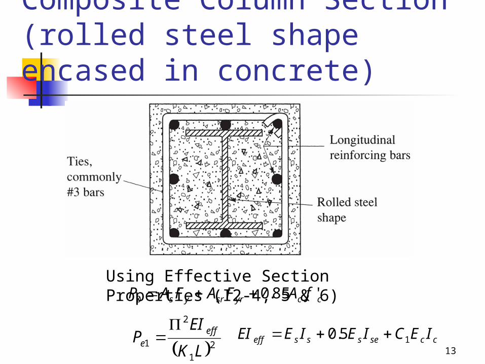
Composite Column Section (rolled steel shape encased in concrete)
AISC I2.1. Encased Composite Columns
AISC I2.2. Filled Composite Columns(Ref: Separate handout with examples.)
13
Composite Column Section (rolled steel shape encased in concrete)
Using Effective Section Properties (I2-4, 5 & 6)ccyrsrys fAFAFAP '85.00
21
2
1LK
EIP effe
ccsessseff IECIEIEEI 15.0

14
Filled Composite Column Example
AISC I2-2b(a)Compact(b)Noncompact(c)Slender

15
Filled Composite Column Example
ccyrsrys fAFAFAP '85.00
ccsessseff IECIEIEEI 35.0
• For compact sections• Ac = bfhf+π(r-t)2+2bf(r-t)+2hf(r-t)
Ac = (8.5 in.)(4.5 in.) + π(0.375 in.)2 + (8.5 in.)(0.375 in.) + 2(4.5 in.)(0.375 in.) = 48.4 in.2
•
• • P0 = (10.4 in.2)(46ksi) + 0.85(48.4 in.2)(5 ksi) = 684kips•
• EIeff = (29,000 kis)(61.8 in.4) + (0.90)(3,900 ksi)(111 in.4) = 2,180,000 kip-in.2
42222
22211 .111)
3
)(4
2)(
2
)((2)
9
8
8)((2
12
))((2
12in
trhtrtr
hbhbIc

16
Filled Composite Column Example
21
2
1LK
EIP effe
• Pe = π2(2,180,000 kip-in.2)/(1.0(14 ft)(12 in./ft))2 = 762 kips
• P0/Pe = 684 kips/762 kips = 0.898 ≤ 2.25
•
• φcPn = 0.75(470 kips) = 353 kips > 336 kips o.k.
kipskipsPP ePpn 470658.0)684(658.0 898.0/
00


