S SinCos ® SCS 60, SCM 60, SCS 70, SCM 70: Motor Feedback Systems with HIPERFACE ® - Interface for Servo Motors D ATA S HEET SCS/SCM series of motor feed- back systems are used worldwide in many different applications and environments. Absolute positioning with 16,384 steps per revolution and a maxi- mum of 4,096 revolutions give a total resolution of 67,108,864 steps. Writing motor-specific data to the electronic type label and program- ming are important features of these series. Select the motor feedback system to suit your individual requirement. Possible product variations: · Plug-in shaft, tapered shaft or hollow shaft with different stator supports · 6 mm or 10 mm shaft with connector or cable exit · Versions for integration, attachment, or standalone versions. 512 sine/ cosine periods Motor Feedback Systems
Transcript
S
SinCos® SCS 60, SCM 60, SCS 70, SCM 70:Motor Feedback Systems with HIPERFACE®-Interface for Servo Motors
DA
TA
SH
EE
T
SCS/SCM series of motor feed-
back systems are used worldwide
in many different applications and
environments.
Absolute positioning with 16,384
steps per revolution and a maxi-
mum of 4,096 revolutions give a
total resolution of 67,108,864
steps.
Writing motor-specific data to the
electronic type label and program-
ming are important features of these
series.
Select the motor feedback system to
suit your individual requirement.
Possible product variations:
· Plug-in shaft, tapered shaft or
hollow shaft with different stator
supports
· 6 mm or 10 mm shaft with
connector or cable exit
· Versions for integration,
attachment, or standalone versions.
512 sine/cosine periods
Motor Feedback Systems
2 SICK-STEGMANN
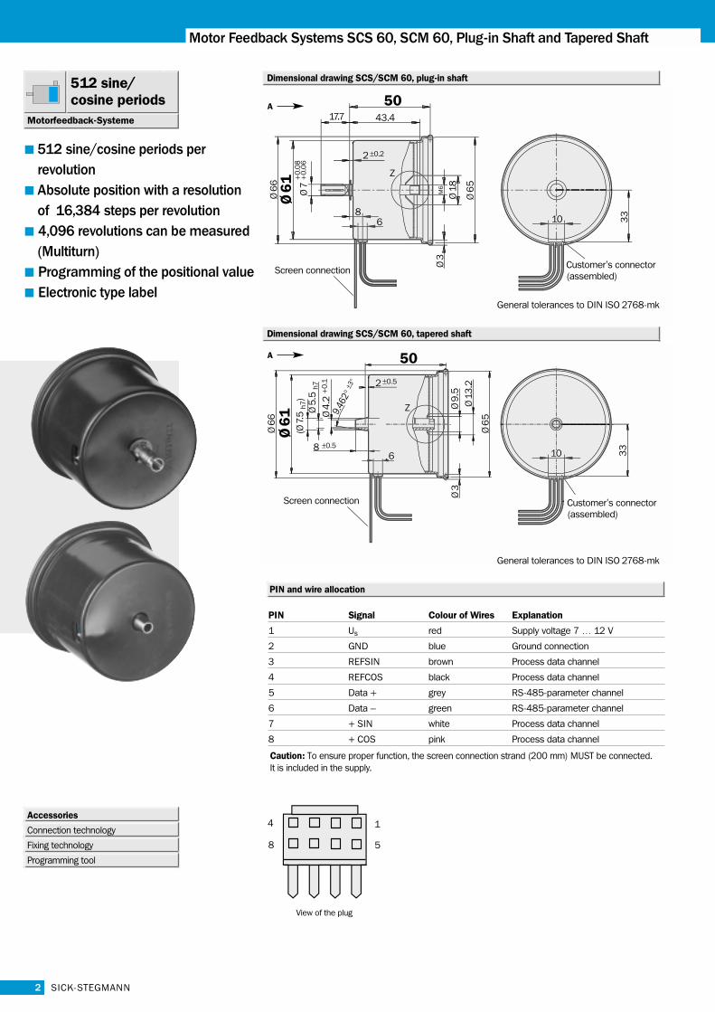
Motor Feedback Systems SCS 60, SCM 60, Plug-in Shaft and Tapered Shaft
512 sine/cosine periods per revolutionAbsolute position with a resolution of 16,384 steps per revolution4,096 revolutions can be measured(Multiturn)Programming of the positional valueElectronic type label
PIN and wire allocation
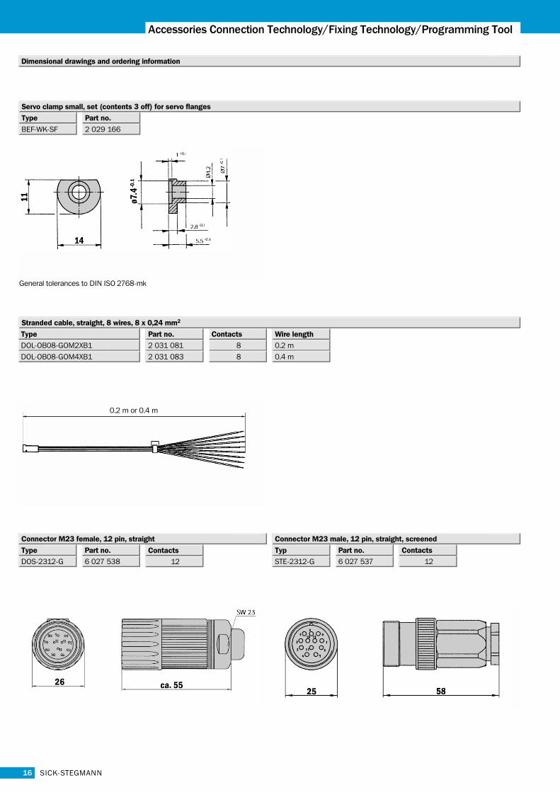
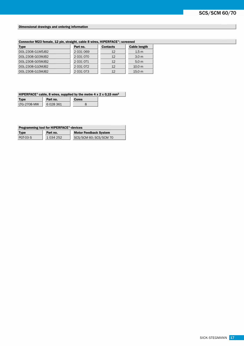
Accessories
Connection technology
Fixing technology
Programming tool
PIN Signal Colour of Wires Explanation
1 Us red Supply voltage 7 … 12 V
2 GND blue Ground connection
3 REFSIN brown Process data channel
4 REFCOS black Process data channel
5 Data + grey RS-485-parameter channel
6 Data – green RS-485-parameter channel
7 + SIN white Process data channel
8 + COS pink Process data channel
Caution: To ensure proper function, the screen connection strand (200 mm) MUST be connected.It is included in the supply.
Dimensional drawing SCS/SCM 60, plug-in shaft
Dimensional drawing SCS/SCM 60, tapered shaft
512 sine/cosine periods
Motorfeedback-Systeme
General tolerances to DIN ISO 2768-mk
General tolerances to DIN ISO 2768-mk
View of the plug
A
A
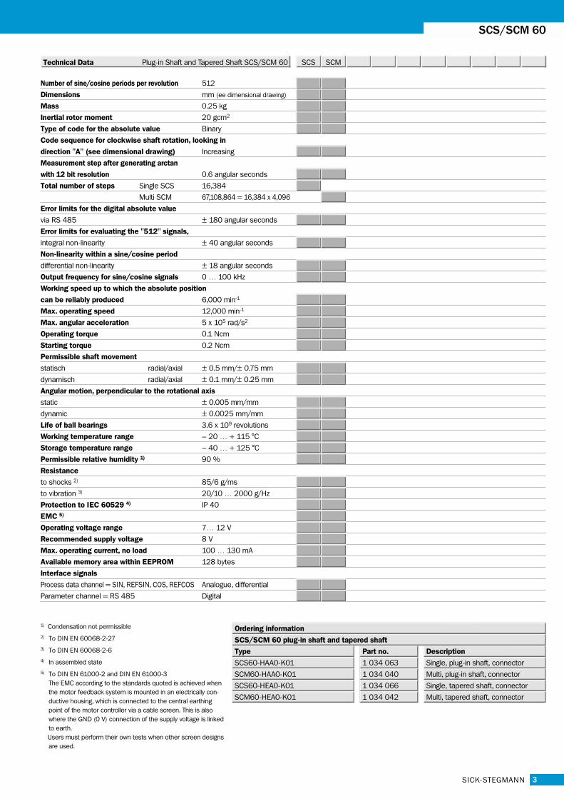
Number of sine/cosine periods per revolution 512
Dimensions mm (ee dimensional drawing)
Mass 0.25 kg
Inertial rotor moment 20 gcm2
Type of code for the absolute value Binary
Code sequence for clockwise shaft rotation, looking in
direction "A" (see dimensional drawing) Increasing
Measurement step after generating arctan
with 12 bit resolution 0.6 angular seconds
Total number of steps Single SCS 16,384
Multi SCM 67,108,864 = 16,384 x 4,096
Error limits for the digital absolute value
via RS 485 ± 180 angular seconds
Error limits for evaluating the "512" signals,
integral non-linearity ± 40 angular seconds
Non-linearity within a sine/cosine period
differential non-linearity ± 18 angular seconds
Output frequency for sine/cosine signals 0 … 100 kHz
Working speed up to which the absolute position
can be reliably produced 6,000 min-1
Max. operating speed 12,000 min-1
Max. angular acceleration 5 x 10⁵ rad/s2
Operating torque 0.1 Ncm
Starting torque 0.2 Ncm
Permissible shaft movement
statisch radial/axial ± 0.5 mm/± 0.75 mm
dynamisch radial/axial ± 0.1 mm/± 0.25 mm
Angular motion, perpendicular to the rotational axis
static ± 0.005 mm/mm
dynamic ± 0.0025 mm/mm
Life of ball bearings 3.6 x 10⁹ revolutions
Working temperature range – 20 … + 115 °C
Storage temperature range – 40 … + 125 °C
Permissible relative humidity 1) 90 %
Resistance
to shocks 2) 85/6 g/ms
to vibration 3) 20/10 … 2000 g/Hz
Protection to IEC 60529 4) IP 40
EMC 5)
Operating voltage range 7… 12 V
Recommended supply voltage 8 V
Max. operating current, no load 100 … 130 mA
Available memory area within EEPROM 128 bytes
Interface signals
Process data channel = SIN, REFSIN, COS, REFCOS Analogue, differential
Parameter channel = RS 485 Digital
3
SCS/SCM 60
SCS SCMTechnical Data Plug-in Shaft and Tapered Shaft SCS/SCM 60
SICK-STEGMANN
1) Condensation not permissible2) To DIN EN 60068-2-273) To DIN EN 60068-2-64) In assembled state5) To DIN EN 61000-2 and DIN EN 61000-3
The EMC according to the standards quoted is achieved whenthe motor feedback system is mounted in an electrically con-ductive housing, which is connected to the central earthingpoint of the motor controller via a cable screen. This is alsowhere the GND (0 V) connection of the supply voltage is linkedto earth.Users must perform their own tests when other screen designsare used.
1 034 063
Part no.
SCS60-HAA0-K01
Type
1 034 040SCM60-HAA0-K01
1 034 066SCS60-HEA0-K01
1 034 042SCM60-HEA0-K01
Description
Ordering information
Single, plug-in shaft, connector
Multi, plug-in shaft, connector
Single, tapered shaft, connector
Multi, tapered shaft, connector
SCS/SCM 60 plug-in shaft and tapered shaft
4 SICK-STEGMANN
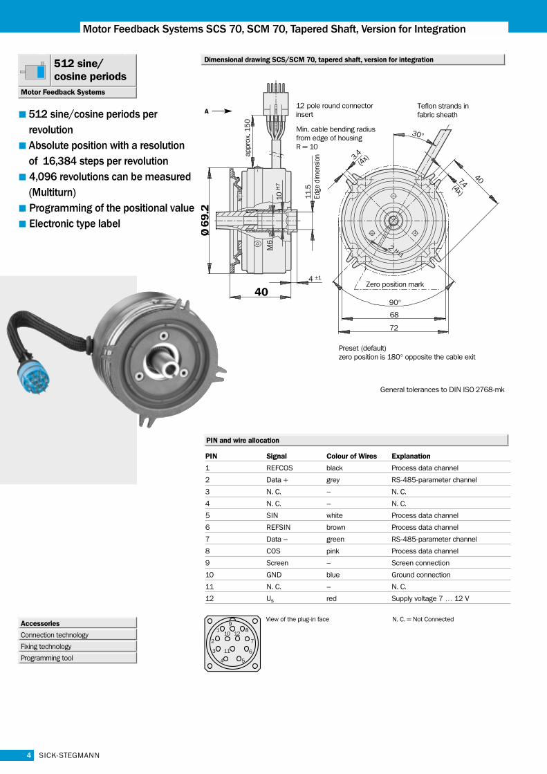
Motor Feedback Systems SCS 70, SCM 70, Tapered Shaft, Version for Integration
512 sine/cosine periods per revolutionAbsolute position with a resolution of 16,384 steps per revolution4,096 revolutions can be measured(Multiturn)Programming of the positional valueElectronic type label
PIN and wire allocation
Dimensional drawing SCS/SCM 70, tapered shaft, version for integration512 sine/cosine periods
Motor Feedback Systems
Accessories
Connection technology
Fixing technology
Programming tool
General tolerances to DIN ISO 2768-mk
PIN Signal Colour of Wires Explanation
1 REFCOS black Process data channel
2 Data + grey RS-485-parameter channel
3 N. C. – N. C.
4 N. C. – N. C.
5 SIN white Process data channel
6 REFSIN brown Process data channel
7 Data – green RS-485-parameter channel
8 COS pink Process data channel
9 Screen – Screen connection
10 GND blue Ground connection
11 N. C. – N. C.
12 Us red Supply voltage 7 … 12 V
View of the plug-in face
A
N. C. = Not Connected
5SICK-STEGMANN
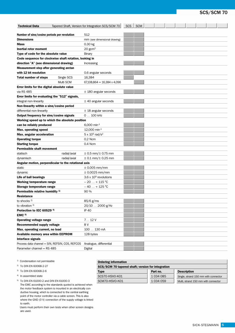
Number of sine/cosine periods per revolution 512
Dimensions mm (see dimensional drawing)
Mass 0.30 kg
Inertial rotor moment 20 gcm2
Type of code for the absolute value Binary
Code sequence for clockwise shaft rotation, looking in
direction "A" (see dimensional drawing) Increasing
Measurement step after generating arctan
with 12 bit resolution 0.6 angular seconds
Total number of steps Single SCS 16,384
Multi SCM 67,108,864 = 16,384 x 4,096
Error limits for the digital absolute value
via RS 485 ± 180 angular seconds
Error limits for evaluating the "512" signals,
integral non-linearity ± 40 angular seconds
Non-linearity within a sine/cosine period
differential non-linearity ± 18 angular seconds
Output frequency for sine/cosine signals 0 … 100 kHz
Working speed up to which the absolute position
can be reliably produced 6,000 min-1
Max. operating speed 12,000 min-1
Max. angular acceleration 5 x 10⁵ rad/s2
Operating torque 0.2 Ncm
Starting torque 0.4 Ncm
Permissible shaft movement
statisch radial/axial ± 0.5 mm/± 0.75 mm
dynamisch radial/axial ± 0.1 mm/± 0.25 mm
Angular motion, perpendicular to the rotational axis
static ± 0.005 mm/mm
dynamic ± 0.0025 mm/mm
Life of ball bearings 3.6 x 10⁹ revolutions
Working temperature range – 20 … + 115 °C
Storage temperature range – 40 … + 125 °C
Permissible relative humidity 1) 90 %
Resistance
to shocks 2) 85/6 g/ms
to vibration 3) 20/10 … 2000 g/Hz
Protection to IEC 60529 4) IP 40
EMC 5)
Operating voltage range 7… 12 V
Recommended supply voltage 8 V
Max. operating current, no load 100 … 130 mA
Available memory area within EEPROM 128 bytes
Interface signals
Process data channel = SIN, REFSIN, COS, REFCOS Analogue, differential
Parameter channel = RS 485 Digital
SCS/SCM 70
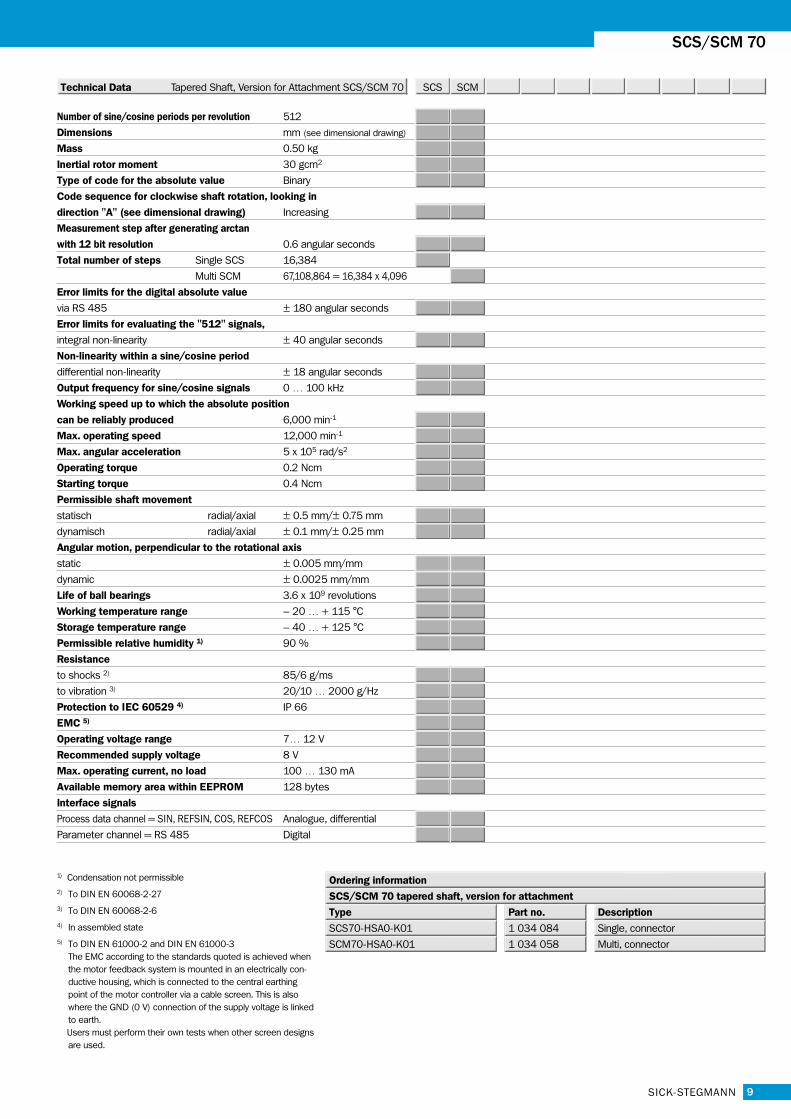
SCS SCMTechnical Data Tapered Shaft, Version for Integration SCS/SCM 70
1) Condensation not permissible2) To DIN EN 60068-2-273) To DIN EN 60068-2-64) In assembled state5) To DIN EN 61000-2 and DIN EN 61000-3
The EMC according to the standards quoted is achieved whenthe motor feedback system is mounted in an electrically con-ductive housing, which is connected to the central earthingpoint of the motor controller via a cable screen. This is alsowhere the GND (0 V) connection of the supply voltage is linkedto earth.Users must perform their own tests when other screen designsare used.
1 034 085
Part no.
SCS70-HSV0-K01
Type
1 034 059SCM70-HSV0-K01
Description
Ordering information
Single, strand 150 mm with connector
Multi, strand 150 mm with connector
SCS/SCM 70 tapered shaft; version for integration
6
Motor Feedback Systems SCS 70, SCM 70, Hollow Shaft 10 mm, Version for Integration
SICK-STEGMANN
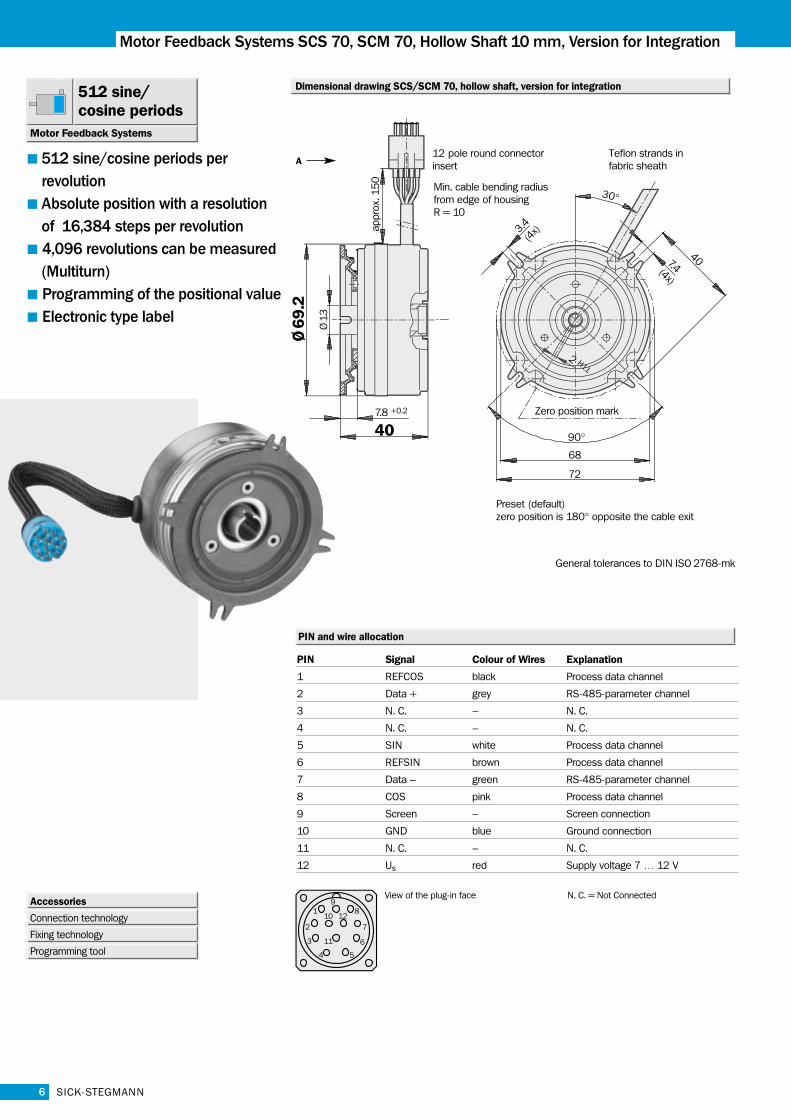
Dimensional drawing SCS/SCM 70, hollow shaft, version for integration512 sine/cosine periods
Motor Feedback Systems
Accessories
Connection technology
Fixing technology
Programming tool
General tolerances to DIN ISO 2768-mk
512 sine/cosine periods per revolutionAbsolute position with a resolution of 16,384 steps per revolution4,096 revolutions can be measured(Multiturn)Programming of the positional valueElectronic type label
A
PIN and wire allocation
PIN Signal Colour of Wires Explanation
1 REFCOS black Process data channel
2 Data + grey RS-485-parameter channel
3 N. C. – N. C.
4 N. C. – N. C.
5 SIN white Process data channel
6 REFSIN brown Process data channel
7 Data – green RS-485-parameter channel
8 COS pink Process data channel
9 Screen – Screen connection
10 GND blue Ground connection
11 N. C. – N. C.
12 Us red Supply voltage 7 … 12 V
View of the plug-in face N. C. = Not Connected
Number of sine/cosine periods per revolution 512
Dimensions mm (see dimensional drawing)
Mass 0.25 kg
Inertial rotor moment 30 gcm2
Type of code for the absolute value Binary
Code sequence for clockwise shaft rotation, looking in
direction "A" (see dimensional drawing) Increasing
Measurement step after generating arctan
with 12 bit resolution 0.6 angular seconds
Total number of steps Single SCS 16,384
Multi SCM 67,108,864 = 16,384 x 4,096
Error limits for the digital absolute value
via RS 485 ± 180 angular seconds
Error limits for evaluating the "512" signals,
integral non-linearity ± 40 angular seconds
Non-linearity within a sine/cosine period
differential non-linearity ± 18 angular seconds
Output frequency for sine/cosine signals 0 … 100 kHz
Working speed up to which the absolute position
can be reliably produced 6,000 min-1
Max. operating speed 12,000 min-1
Max. angular acceleration 5 x 10⁵ rad/s2
Operating torque 0.1 Ncm
Starting torque 0.2 Ncm
Permissible shaft movement
statisch radial/axial ± 0.5 mm/± 0.75 mm
dynamisch radial/axial ± 0.1 mm/± 0.25 mm
Angular motion, perpendicular to the rotational axis
static ± 0.005 mm/mm
dynamic ± 0.0025 mm/mm
Life of ball bearings 3.6 x 10⁹ revolutions
Working temperature range – 20 … + 115 °C
Storage temperature range – 40 … + 125 °C
Permissible relative humidity 1) 90 %
Resistance
to shocks 2) 85/6 g/ms
to vibration 3) 20/10 … 2000 g/Hz
Protection to IEC 60529 4) IP 40
EMC 5)
Operating voltage range 7… 12 V
Recommended supply voltage 8 V
Max. operating current, no load 100 … 130 mA
Available memory area within EEPROM 128 bytes
Interface signals
Process data channel = SIN, REFSIN, COS, REFCOS Analogue, differential
Parameter channel = RS 485 Digital
7SICK-STEGMANN
SCS/SCM 70
SCS SCMTechnical Data Hollow Shaft, Version for Integration SCS/SCM 70
1) Condensation not permissible2) To DIN EN 60068-2-273) To DIN EN 60068-2-64) In assembled state5) To DIN EN 61000-2 and DIN EN 61000-3
The EMC according to the standards quoted is achieved whenthe motor feedback system is mounted in an electrically con-ductive housing, which is connected to the central earthingpoint of the motor controller via a cable screen. This is alsowhere the GND (0 V) connection of the supply voltage is linkedto earth.Users must perform their own tests when other screen designsare used.
1 034 071
Part no.
SCS70-HLV0-K01
Type
1 034 048SCM70-HLV0-K01
Description
Ordering information
Single, strand 150 mm with connector
Multi, strand 150 mm with connector
SCS/SCM 70 hollow shaft 10 mm; version for integration
8
Motor Feedback Systems SCS 70, SCM 70, Tapered Shaft, Version for Attachment
SICK-STEGMANN
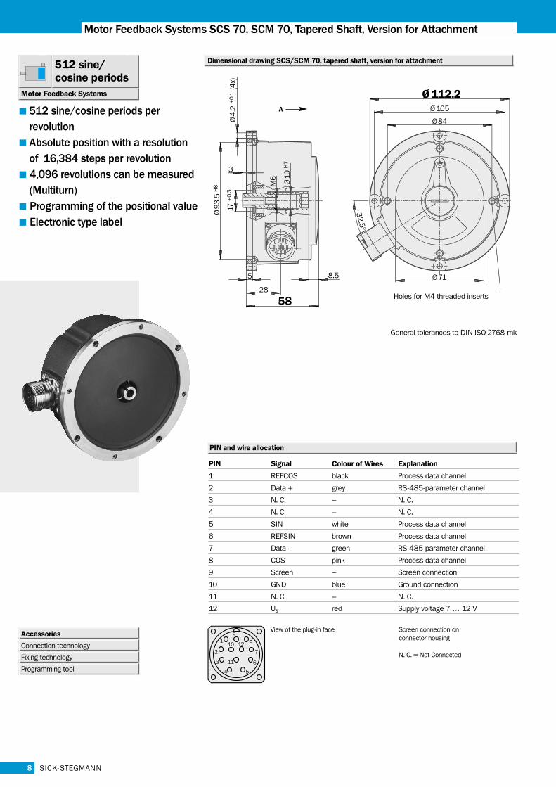
Dimensional drawing SCS/SCM 70, tapered shaft, version for attachment512 sine/cosine periods
Motor Feedback Systems
Accessories
Connection technology
Fixing technology
Programming tool
General tolerances to DIN ISO 2768-mk
512 sine/cosine periods per revolutionAbsolute position with a resolution of 16,384 steps per revolution4,096 revolutions can be measured(Multiturn)Programming of the positional valueElectronic type label
A
PIN and wire allocation
PIN Signal Colour of Wires Explanation
1 REFCOS black Process data channel
2 Data + grey RS-485-parameter channel
3 N. C. – N. C.
4 N. C. – N. C.
5 SIN white Process data channel
6 REFSIN brown Process data channel
7 Data – green RS-485-parameter channel
8 COS pink Process data channel
9 Screen – Screen connection
10 GND blue Ground connection
11 N. C. – N. C.
12 Us red Supply voltage 7 … 12 V
View of the plug-in face Screen connection on connector housing
N. C. = Not Connected
Number of sine/cosine periods per revolution 512
Dimensions mm (see dimensional drawing)
Mass 0.50 kg
Inertial rotor moment 30 gcm2
Type of code for the absolute value Binary
Code sequence for clockwise shaft rotation, looking in
direction "A" (see dimensional drawing) Increasing
Measurement step after generating arctan
with 12 bit resolution 0.6 angular seconds
Total number of steps Single SCS 16,384
Multi SCM 67,108,864 = 16,384 x 4,096
Error limits for the digital absolute value
via RS 485 ± 180 angular seconds
Error limits for evaluating the "512" signals,
integral non-linearity ± 40 angular seconds
Non-linearity within a sine/cosine period
differential non-linearity ± 18 angular seconds
Output frequency for sine/cosine signals 0 … 100 kHz
Working speed up to which the absolute position
can be reliably produced 6,000 min-1
Max. operating speed 12,000 min-1
Max. angular acceleration 5 x 10⁵ rad/s2
Operating torque 0.2 Ncm
Starting torque 0.4 Ncm
Permissible shaft movement
statisch radial/axial ± 0.5 mm/± 0.75 mm
dynamisch radial/axial ± 0.1 mm/± 0.25 mm
Angular motion, perpendicular to the rotational axis
static ± 0.005 mm/mm
dynamic ± 0.0025 mm/mm
Life of ball bearings 3.6 x 10⁹ revolutions
Working temperature range – 20 … + 115 °C
Storage temperature range – 40 … + 125 °C
Permissible relative humidity 1) 90 %
Resistance
to shocks 2) 85/6 g/ms
to vibration 3) 20/10 … 2000 g/Hz
Protection to IEC 60529 4) IP 66
EMC 5)
Operating voltage range 7… 12 V
Recommended supply voltage 8 V
Max. operating current, no load 100 … 130 mA
Available memory area within EEPROM 128 bytes
Interface signals
Process data channel = SIN, REFSIN, COS, REFCOS Analogue, differential
Parameter channel = RS 485 Digital
9SICK-STEGMANN
SCS/SCM 70
SCS SCMTechnical Data Tapered Shaft, Version for Attachment SCS/SCM 70
1) Condensation not permissible2) To DIN EN 60068-2-273) To DIN EN 60068-2-64) In assembled state5) To DIN EN 61000-2 and DIN EN 61000-3
The EMC according to the standards quoted is achieved whenthe motor feedback system is mounted in an electrically con-ductive housing, which is connected to the central earthingpoint of the motor controller via a cable screen. This is alsowhere the GND (0 V) connection of the supply voltage is linkedto earth.Users must perform their own tests when other screen designsare used.
1 034 084
Part no.
SCS70-HSA0-K01
Type
1 034 058SCM70-HSA0-K01
Description
Ordering information
Single, connector
Multi, connector
SCS/SCM 70 tapered shaft, version for attachment
10
Motor Feedback Systems SCS 70, SCM 70, Hollow Shaft 10 mm, Version for Attachment
SICK-STEGMANN
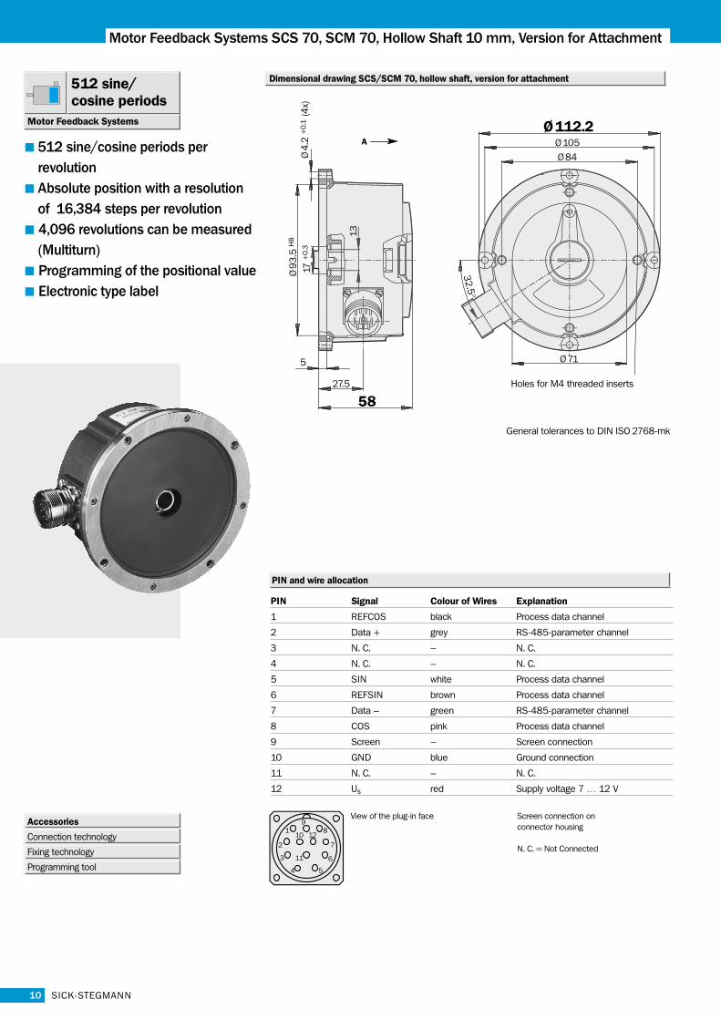
Dimensional drawing SCS/SCM 70, hollow shaft, version for attachment512 sine/cosine periods
Motor Feedback Systems
Accessories
Connection technology
Fixing technology
Programming tool
512 sine/cosine periods per revolutionAbsolute position with a resolution of 16,384 steps per revolution4,096 revolutions can be measured(Multiturn)Programming of the positional valueElectronic type label
General tolerances to DIN ISO 2768-mk
A
PIN and wire allocation
PIN Signal Colour of Wires Explanation
1 REFCOS black Process data channel
2 Data + grey RS-485-parameter channel
3 N. C. – N. C.
4 N. C. – N. C.
5 SIN white Process data channel
6 REFSIN brown Process data channel
7 Data – green RS-485-parameter channel
8 COS pink Process data channel
9 Screen – Screen connection
10 GND blue Ground connection
11 N. C. – N. C.
12 Us red Supply voltage 7 … 12 V
View of the plug-in face Screen connection on connector housing
N. C. = Not Connected
Number of sine/cosine periods per revolution 512
Dimensions mm (see dimensional drawing)
Mass 0.50 kg
Inertial rotor moment 30 gcm2
Type of code for the absolute value Binary
Code sequence for clockwise shaft rotation, looking in
direction "A" (see dimensional drawing) Increasing
Measurement step after generating arctan
with 12 bit resolution 0.6 angular seconds
Total number of steps Single SCS 16,384
Multi SCM 67,108,864 = 16,384 x 4,096
Error limits for the digital absolute value
via RS 485 ± 180 angular seconds
Error limits for evaluating the "512" signals,
integral non-linearity ± 40 angular seconds
Non-linearity within a sine/cosine period
differential non-linearity ± 18 angular seconds
Output frequency for sine/cosine signals 0 … 100 kHz
Working speed up to which the absolute position
can be reliably produced 6,000 min-1
Max. operating speed 12,000 min-1
Max. angular acceleration 5 x 10⁵ rad/s2
Operating torque 0.2 Ncm
Starting torque 0.4 Ncm
Permissible shaft movement
statisch radial/axial ± 0.5 mm/± 0.75 mm
dynamisch radial/axial ± 0.1 mm/± 0.25 mm
Angular motion, perpendicular to the rotational axis
static ± 0.005 mm/mm
dynamic ± 0.0025 mm/mm
Life of ball bearings 3.6 x 10⁹ revolutions
Working temperature range – 20 … + 115 °C
Storage temperature range – 40 … + 125 °C
Permissible relative humidity 1) 90 %
Resistance
to shocks 2) 85/6 g/ms
to vibration 3) 20/10 … 2000 g/Hz
Protection to IEC 60529 4) IP 66
EMC 5)
Operating voltage range 7… 12 V
Recommended supply voltage 8 V
Max. operating current, no load 100 … 130 mA
Available memory area within EEPROM 128 bytes
Interface signals
Process data channel = SIN, REFSIN, COS, REFCOS Analogue, differential
Parameter channel = RS 485 Digital
11SICK-STEGMANN
SCS/SCM 70
Technical Data Hollow Shaft, Version for Attachment SCS/SCM 70
1) Condensation not permissible2) To DIN EN 60068-2-273) To DIN EN 60068-2-64) In assembled state5) To DIN EN 61000-2 and DIN EN 61000-3
The EMC according to the standards quoted is achieved whenthe motor feedback system is mounted in an electrically con-ductive housing, which is connected to the central earthingpoint of the motor controller via a cable screen. This is alsowhere the GND (0 V) connection of the supply voltage is linkedto earth.Users must perform their own tests when other screen designsare used.
1 034 069
Part no.
SCS70-HLA0-K01
Type
1 034 047SCM70-HLA0-K01
Description
Ordering information
Single, connector
Multi, connector
SCS/SCM 70 hollow shaft 10 mm; version for attachment
SCS SCM
12
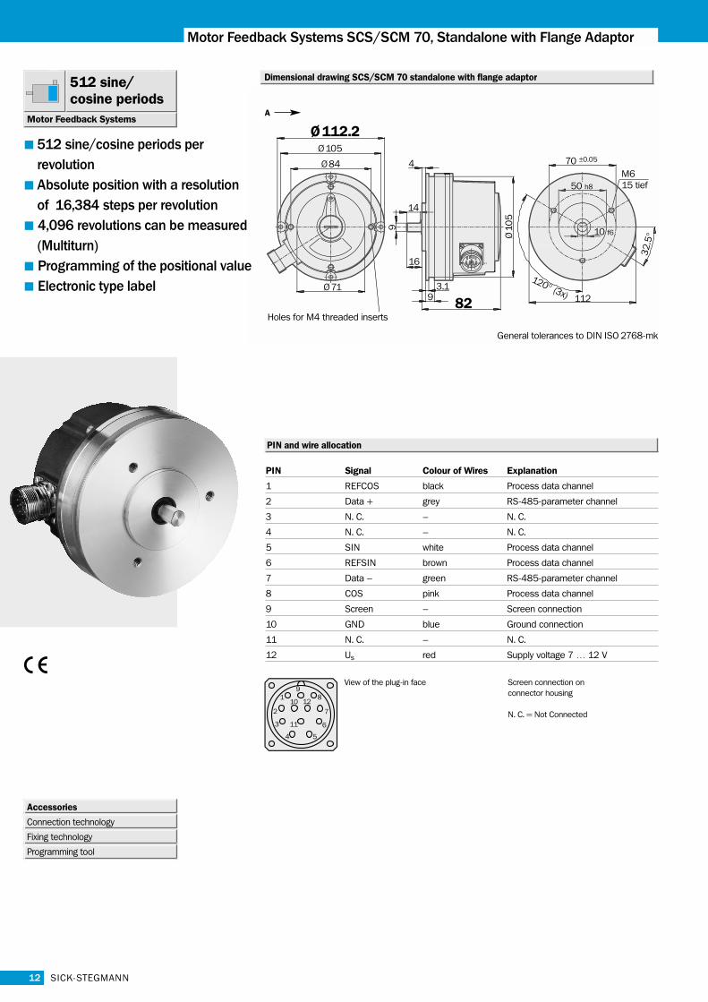
Motor Feedback Systems SCS/SCM 70, Standalone with Flange Adaptor
SICK-STEGMANN
PIN and wire allocation
PIN Signal Colour of Wires Explanation
1 REFCOS black Process data channel
2 Data + grey RS-485-parameter channel
3 N. C. – N. C.
4 N. C. – N. C.
5 SIN white Process data channel
6 REFSIN brown Process data channel
7 Data – green RS-485-parameter channel
8 COS pink Process data channel
9 Screen – Screen connection
10 GND blue Ground connection
11 N. C. – N. C.
12 Us red Supply voltage 7 … 12 V
Dimensional drawing SCS/SCM 70 standalone with flange adaptor
Screen connection on connector housing
N. C. = Not Connected
Accessories
Connection technology
Fixing technology
Programming tool
General tolerances to DIN ISO 2768-mk
512 sine/cosine periods
Motor Feedback Systems
512 sine/cosine periods per revolutionAbsolute position with a resolution of 16,384 steps per revolution4,096 revolutions can be measured(Multiturn)Programming of the positional valueElectronic type label
View of the plug-in face
A
13SICK-STEGMANN
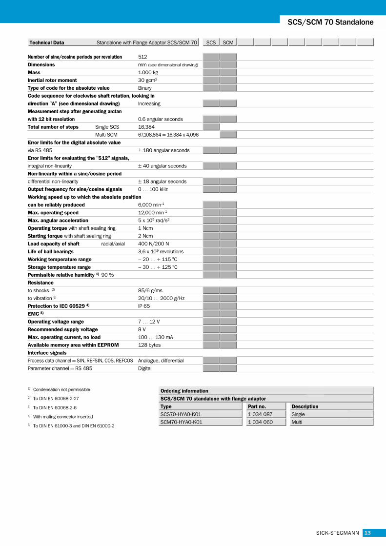
Number of sine/cosine periods per revolution 512
Dimensions mm (see dimensional drawing)
Mass 1.000 kg
Inertial rotor moment 30 gcm2
Type of code for the absolute value Binary
Code sequence for clockwise shaft rotation, looking in
direction "A" (see dimensional drawing) Increasing
Measurement step after generating arctan
with 12 bit resolution 0.6 angular seconds
Total number of steps Single SCS 16,384
Multi SCM 67,108,864 = 16,384 x 4,096
Error limits for the digital absolute value
via RS 485 ± 180 angular seconds
Error limits for evaluating the "512" signals,
integral non-linearity ± 40 angular seconds
Non-linearity within a sine/cosine period
differential non-linearity ± 18 angular seconds
Output frequency for sine/cosine signals 0 … 100 kHz
Working speed up to which the absolute position
can be reliably produced 6,000 min-1
Max. operating speed 12,000 min-1
Max. angular acceleration 5 x 10⁵ rad/s2
Operating torque with shaft sealing ring 1 Ncm
Starting torque with shaft sealing ring 2 Ncm
Load capacity of shaft radial/axial 400 N/200 N
Life of ball bearings 3,6 x 10⁹ revolutions
Working temperature range – 20 … + 115 °C
Storage temperature range – 30 … + 125 °C
Permissible relative humidity 1) 90 %
Resistance
to shocks 2) 85/6 g/ms
to vibration 3) 20/10 … 2000 g/Hz
Protection to IEC 60529 4) IP 65
EMC 5)
Operating voltage range 7 … 12 V
Recommended supply voltage 8 V
Max. operating current, no load 100 … 130 mA
Available memory area within EEPROM 128 bytes
Interface signals
Process data channel = SIN, REFSIN, COS, REFCOS Analogue, differential
Parameter channel = RS 485 Digital
SCS/SCM 70 Standalone
Technical Data Standalone with Flange Adaptor SCS/SCM 70
1) Condensation not permissible
2) To DIN EN 60068-2-27
3) To DIN EN 60068-2-6
4) With mating connector inserted
5) To DIN EN 61000-3 and DIN EN 61000-2
1 034 087
Part no.
SCS70-HYA0-K01
Type
1 034 060SCM70-HYA0-K01
Description
Ordering information
Single
Multi
SCS/SCM 70 standalone with flange adaptor
SCS SCM
14
SCS/SCM 60/70
SICK-STEGMANN
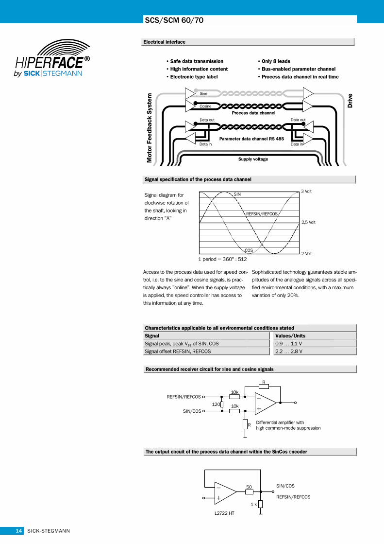
Electrical interface
1 period = 360° : 512
Access to the process data used for speed con-
trol, i.e. to the sine and cosine signals, is prac-
tically always "online". When the supply voltage
is applied, the speed controller has access to
this information at any time.
Sophisticated technology guarantees stable am-
plitudes of the analogue signals across all speci-
fied environmental conditions, with a maximum
variation of only 20%.
Signal Values/Units
Signal peak, peak Vss of SIN, COS 0.9 … 1.1 V
Signal offset REFSIN, REFCOS 2.2 … 2.8 V
Characteristics applicable to all environmental conditions stated
• Safe data transmission • Only 8 leads
• High information content • Bus-enabled parameter channel
• Electronic type label • Process data channel in real time
Mot
or F
eedb
ack
Sys
tem
Driv
e
Process data channel
Parameter data channel RS 485
Supply voltage
Sine
Cosine
Data out Data out
Data in Data in
Signal specification of the process data channel
Signal diagram for
clockwise rotation of
the shaft, looking in
direction "A"REFSIN/REFCOS
COS
SIN3 Volt
2,5 Volt
2 Volt
Recommended receiver circuit for sine and cosine signals
The output circuit of the process data channel within the SinCos encoder
–
+
SIN/COS
REFSIN/REFCOS
50
1 k
L2722 HT
15SICK-STEGMANN
SCS/SCM 60/70
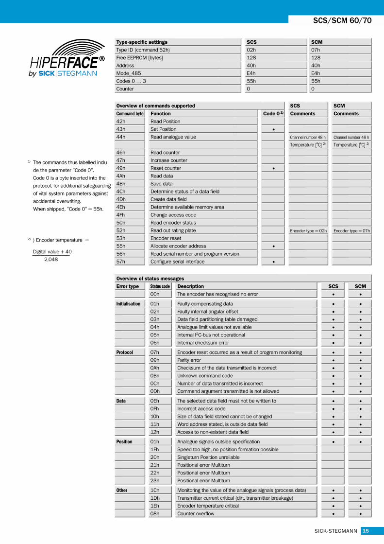
1) The commands thus labelled inclu
de the parameter "Code 0".
Code 0 is a byte inserted into the
protocol, for additional safeguarding
of vital system parameters against
accidental overwriting.
When shipped, "Code 0" = 55h.
2) ) Encoder temperature =
Digital value + 40
2,048
SCS
Type ID (command 52h) 02h
Free EEPROM [bytes] 128
SCM
07h
128
Address 40h 40h
Mode_485 E4h E4h
Codes 0 … 3 55h 55h
Counter
SCS SCM
Command byte Function Code 0 1) Comments Comments
42h Read Position
43h Set Position •44h Read analogue value Channel number 48 h Channel number 48 h
Temperature [°C] 2) Temperature [°C] 2)
46h Read counter
47h Increase counter
49h Reset counter •4Ah Read data
4Bh Save data
4Ch Determine status of a data field
4Dh Create data field
4Eh Determine available memory area
4Fh Change access code
50h Read encoder status
52h Read out rating plate Encoder type = 02h Encoder type = 07h
53h Encoder reset
55h Allocate encoder address •56h Read serial number and program version
57h Configure serial interface •
0 0
Type-specific settings
Overview of commands cupported
Error type Status code Description
00h The encoder has recognised no error
Initialisation 01h Faulty compensating data
02h Faulty internal angular offset
03h Data field partitioning table damaged
04h Analogue limit values not available
05h Internal I2C-bus not operational
06h Internal checksum error
Protocol 07h Encoder reset occurred as a result of program monitoring
09h Parity error
0Ah Checksum of the data transmitted is incorrect
0Bh Unknown command code
0Ch Number of data transmitted is incorrect
0Dh Command argument transmitted is not allowed
Data 0Eh The selected data field must not be written to
0Fh Incorrect access code
10h Size of data field stated cannot be changed
11h Word address stated, is outside data field
12h Access to non-existent data field
Position 01h Analogue signals outside specification
1Fh Speed too high, no position formation possible
Other 1Ch Monitoring the value of the analogue signals (process data) •1Dh Transmitter current critical (dirt, transmitter breakage) •1Eh Encoder temperature critical •08h Counter overflow •