86


Cisco Press800 East 96th StreetIndianapolis, IN 46240 USA
Cisco Press
End-to-End QoS Network Design
Tim Szigeti, CCIE No. 9794, and Christina Hattingh

ii
End-to-End QoS Network DesignTim Szigeti, CCIE No. 9794, Christina Hattingh
Copyright © 2005 Cisco Systems, Inc.
Published by:Cisco Press800 East 96th Street Indianapolis, IN 46240 USA
All rights reserved. No part of this book may be reproduced or transmitted in any form or by any means, electronic or mechanical, including photocopying, recording, or by any information storage and retrieval system, without written permission from the publisher, except for the inclusion of brief quotations in a review.
Library of Congress Cataloging-in-Publication Number: 2003111984
ISBN: 1-58705-176-1
Trademark AcknowledgmentsAll terms mentioned in this book that are known to be trademarks or service marks have been appropriately capital-ized. Cisco Press or Cisco Systems, Inc., cannot attest to the accuracy of this information. Use of a term in this book should not be regarded as affecting the validity of any trademark or service mark.
Warning and DisclaimerThis book is designed to provide information about Quality-of-Service network design best-practice recommenda-tions. Every effort has been made to make this book as complete and as accurate as possible, but no warranty or fitness is implied.
The information is provided on an “as is” basis. The authors, Cisco Press, and Cisco Systems, Inc., shall have neither liability nor responsibility to any person or entity with respect to any loss or damages arising from the information contained in this book or from the use of the discs or programs that may accompany it.
The opinions expressed in this book belong to the author and are not necessarily those of Cisco Systems, Inc.
Corporate and Government SalesCisco Press offers excellent discounts on this book when ordered in quantity for bulk purchases or special sales.
For more information please contact:U.S. Corporate and Government Sales 1-800-382-3419 [email protected]
For sales outside the U.S. please contact: International Sales [email protected]
Feedback InformationAt Cisco Press, our goal is to create in-depth technical books of the highest quality and value. Each book is crafted with care and precision, undergoing rigorous development that involves the unique expertise of members from the professional technical community.
Readers’ feedback is a natural continuation of this process. If you have any comments regarding how we could improve the quality of this book or otherwise alter it to better suit your needs, you can contact us through e-mail at [email protected]. Please make sure to include the book title and ISBN in your message.
We greatly appreciate your assistance.
Printed in the United States of America.
Ninth Printing: September 2012

iii
Publisher John WaitEditor-in-Chief John KaneCisco Representative Anthony WolfendenCisco Press Program Manager Nannette M. NobleExecutive Editor Christopher ClevelandAcquisitions Editor Michelle GrandinProduction Manager Patrick KanouseDevelopment Editor Howard A. JonesCopy Editor Krista HansingTechnical Editors Frank Knox
Anna ToConnie Varner
Team Coordinator Tammi BarnettCover Designer Louisa AdairComposition Octal Publishing, Inc.Indexer Eric SchroederProofreader Tonya Cupp

iv
About the AuthorsTim Szigeti, CCIE No. 9794, attended the University of British Columbia, where he majored in management information systems. After graduating, Tim joined Cisco Systems and soon after began to specialize in Quality-of-Service technologies, supporting technical marketing initiatives for the Cisco Class Data acquisition, which led to the Cisco QoS Policy Manager (QPM) product. After supporting QPM through several generations and serving as product manager for the Cisco Quality of Service Device Manager (QDM) product, Tim joined the Enterprise Solu-tions Engineering team and led large-scale testing initiatives of campus, WAN, and VPN QoS designs. Tim now belongs to the newly formed Technology Solutions Engineering team within the Cisco Central Technical Marketing organization. There, he continues to define and drive strategic QoS solutions across Cisco technology groups and business units while working with many Fortune 500 companies—both enterprise and service providers—provid-ing QoS design expertise.
Christina Hattingh is a member of the technical staff in the Multiservice Customer Edge Business Unit of Cisco Systems. These products, including the Cisco 2600, 3600, and 3700 series access router platforms, were some of the first Cisco platforms to converge voice and data traffic onto an IP network by offering TDM voice interfaces, WAN interfaces, and critical QoS features, while later integrating call control elements into the router-based plat-form itself. In this role, she trains Cisco sales staff and advises customers on voice network deployment and design.
About the Technical EditorsFrank Knox has more than 37 years of telecommunications experience. During his career at IBM, Frank held posi-tions in field service, field support, service planning, and education; his final position before retirement was curric-ulum manager for IBM’s Network Education in North America. After leaving IBM, Frank held the position of network engineering manager for GTE Directories, where he was responsible for the company’s voice and data net-work design and support. Concurrent with his work at IBM and GTE, Frank taught as an adjunct professor for the University of Dallas MBA program. For the past six years, Frank has worked for Skyline Computer as a senior instructor and consultant; he is currently Skyline’s chief technical officer (CTO). Frank holds two CCIE certifica-tions (R&S and SNA/IP); he also has a master’s degree in telecommunications from Pace University.
Anna To has worked with Cisco for more than three years as a software/deployment engineer on the ITD QoS team. One of Anna’s key tasks is to promote QoS deployment and increase the understanding of QoS technology in the field. Anna works on the Modular QoS CLI (MQC) solution team to bring consistency in QoS configuration across various Cisco platforms. In addition, Anna is involved with the AutoQoS project to simplify QoS deployment.
Connie Varner is a technical marketing engineer in the Cisco Enterprise Systems Engineering group. She has extensive experience designing and testing large-scale networks based on customer requirements, in part based on four years of experience with the Cisco Customer Proof of Concept Labs. Connie specializes in QoS designs that meet the needs of converged data, voice and video networks, and designs that involve IPSec VPNs.
v
DedicationsTim: This book is obviously dedicated to my wife; otherwise, of course, she’d kill me. It amuses me to think that if others are actually reading this, they probably think I’m only joking—but, alas, the Greek capacity for vengeance is no laughing matter. I cancelled far too many dates, stayed in my office and labs far too many weekends, and stared blankly into space (thinking about these designs) far too many times (while she was talking to me) to ever allow the thought of not dedicating this work to her to even cross my tiny xeno-brain.
I know, I know, it’s not a work of literature or a collection of poetry: It’s just a technical book—boring to tears for any not interested in the subject (and probably just boring to yawns for the rest). But, for whatever it’s worth, I’m dedicating it to you, Lella. I love you with all my heart.
Christina: To Robert Verkroost and Ria and Willie Hattingh, who unfailingly support my various forays into the publishing world.

vi
AcknowledgmentsOff the top, I’d like to thank my friend and co-worker Dave Barton, who—although he was extremely busy down-ing beers at Chicago’s Navy Pier—gallantly managed to sic Brett Bartow onto me, which got the ball rolling on this whole project. (Dave, did you make it back okay to the hotel that night?)
Many thanks to Todd Truitt, one of the top talents at Cisco, for inviting my collaboration on the original AVVID QoS Design Guide, hiring me onto his design team, and recommending Christina as a co-author for this project. Do you ever get tired of being right, Todd?
Thanks also to Neil Anderson, Joel King, Ted Hannock, and Steve Ochmanski for guidance and collaboration on IPSec V3PN designs. Thanks for letting me leverage your excellent and thorough work so that I did not to have to reinvent the wheel on these designs.
Thank you, Mike Herbert, for your brilliant flash of using QoS for DoS/worm mitigation via the Scavenger class. Though you derailed and postponed many whitepapers and publications (including this one), you opened up a whole new scope of application for QoS technologies—and we’re all better off for it.
Thank you, too, Alex Dolan, for building out multiple large-scale MPLS VPN testbeds for me and continually tweaking them to suit my mood-of-the-day. I don’t know where your patience or your good nature comes from, but they’re most appreciated. Thanks, too, for nudging me back into playing ice hockey. Next time I break a leg or chip a tooth, I’ll think of you and grimace.
Muchos gracias, Arlindo Callejas, for being much more than my awesome lab administrator. You always went out of your way for me and got me everything I ever needed—instantly. Sometimes I’m afraid to ask where you sourced the gear you did. (I’m not sure whether those 10GE linecards “fell off the back of a Cisco truck” or what, but they sure came in handy at just the right time.)
A round of applause is merited by the technical reviewers. Having done this before myself, I can genuinely appreci-ate the time, effort, and painstaking attention to detail that goes into this process. Frank, your comments were right on and helped make this a better book. Anna, is there anything you don’t know about Cisco QoS? I’m very thankful you took time out of your extremely busy schedule, developing code while helping anyone and everyone on planet Earth (and some nearby systems) that are having QoS problems. And Connie, if you hadn’t reviewed this work, I would not have submitted it for publication. You’re simply the best technical reviewer—and one of the sharpest engineers—I’ve ever had the pleasure of working with.
Thank you Howard Jones for your excellent editing and coordinating the complex content review and copy review processes. And thank you, too, Patrick Kanouse for managing the production of this publication and allowing me to make hundreds of last-minute edits in the galley-review phase (when edits are to be kept at a minimum). How you put up with me I'll never know, but I truly appreciate your patience and desire to help make this book as correct and as current as possible. Also thank you Chris Cleveland for your fine recommendations and guidance during the course of production.
I need to extend thanks also to Debbie Morrison, who is, in my opinion, the best technical writer—period. Debbie, as I’ve said over and over again, you polish my ugly little chunks of coal into beautiful diamonds. I love how I can barely recognize my own work once you’ve done your magic. I’ll truly miss working with you now that you’ve gone on to bigger and better things. (I’m so terrified of the future—who’s going to make me look good now?)
Brett Bartow, what can I say? This would never have happened without you. Time and time again, it seemed to fall by the wayside, but your persistence, perseverance, and patience kept it all going. Thank you. You didn’t back off, and I’m glad for it. Your guidance has been uncanny, and your vision has paid off. Thanks also to your production team.
And lastly, thank you, Christina. You made it fun. Right when I read your first draft of your first chapter, I knew you were the best person to embark on this project with (even though you write like an engineer!). Thank you for sacri-ficing so many weekends on this (thank Robert for me too). I know this is only one of many publishing projects you’re pursuing; all I ask is that you save me an autograph before you move to Hawaii and start on your best-seller!
vii
Contents at a GlanceIntroduction xxii
Part I Introduction to QoS 3
Chapter 1 Introduction to QoS 5
Chapter 2 QoS Design Overview 33
Part II QoS Toolset 67
Chapter 3 Classification and Marking Tools 69
Chapter 4 Policing and Shaping Tools 103
Chapter 5 Congestion-Management Tools 133
Chapter 6 Congestion-Avoidance Tools 159
Chapter 7 Link-Specific Tools 169
Chapter 8 Bandwidth Reservation 195
Chapter 9 Call Admission Control (CAC) 205
Chapter 10 Catalyst QoS Tools 223
Chapter 11 WLAN QoS Tools 269
Part III LAN QoS Design 287
Chapter 12 Campus QoS Design 289
Part IV WAN QoS Design 445
Chapter 13 WAN Aggregator QoS Design 447
Chapter 14 Branch Router QoS Design 513
viii
Part V VPN QoS Design 545
Chapter 15 MPLS VPN QoS Design 547
Chapter 16 IPSec VPN QoS Design 635
Appendix QoS “At-A-Glance” Summaries 701
Index 713
ix
Table of ContentsIntroduction xxii
Part I Introduction to QoS 3
Chapter 1 Introduction to QoS 5
A Brief Historical Perspective 5
QoS Evolution 7
User Network Expectations 9End User 9Information Technologies Management 9
Understanding QoS 10End-to-End QoS 10All Packets Are (Not) Equal 11The Challenges of Converged Networks 12
QoS Models 14IntServ Overview 15DiffServ Overview 16
Introduction to the QoS Toolset 17
Simplifying QoS 19Modular QoS Command-Line Interface 19QoS Baseline 20Default Behavior 21Cross-Platform Feature Consistency 24Automatic QoS 24
If I Have AutoQoS, Why Should I Be Reading This Book? 26
The Continuing Evolution of QoS 29
Summary 29
Further Reading 30General 30IntServ 30DiffServ 31AutoQoS 31

x
Chapter 2 QoS Design Overview 33
QoS Requirements of VoIP 33Voice (Bearer Traffic) 33Call-Signaling Traffic 38
QoS Requirements of Video 39Interactive-Video 39Streaming-Video 41
QoS Requirements of Data 42Best-Effort Data 44Bulk Data 44Transactional Data/Interactive Data 45Locally Defined Mission-Critical Data 45DLSw+ Considerations 47
QoS Requirements of the Control Plane 48IP Routing 48Network-Management 49
Scavenger Class 49
DoS and Worm Mitigation Strategy Through Scavenger Class QoS 50
Principles of QoS Design 54General QoS Design Principles 55Classification and Marking Principles 57Policing and Markdown Principles 57Queuing and Dropping Principles 58DoS and Worm Mitigation Principles 61Deployment Principles 62
Summary 63
Further Reading 64
Part II QoS Toolset 67
Chapter 3 Classification and Marking Tools 69
Classification Tools 70Modular QoS Command-Line Interface Class Maps 71Network-Based Application Recognition 73

xi
Marking Tools 77Class-Based Marking 78Class-Based Policing 78Committed Access Rate 79Policy-Based Routing 79Voice Gateway Packet Marking 79Layer 2 Marking Fields 81Layer 3 Marking Fields 86Translating Layer 2 and Layer 3 Packet Markings 90
Summary 98
Further Reading 99General 99DiffServ 99L2 Protocol Tunneling 100VPN 100NBAR 100MPLS 100IP—ATM/Frame Relay Bundles 101Level 2 to Level 3 Packet-Marking Translation 101
Chapter 4 Policing and Shaping Tools 103
Token Bucket Algorithms 105
Policers 107Policers as Markers 107Committed Access Rate 107Class-Based Policing 109
Shapers 118Shaping Algorithms 120Shaping on ATM and Frame Relay Networks 121Generic Traffic Shaping 126Class-Based Shaping 126
Further Reading 128DiffServ Policing Standards 128Policing 129ATM PVC Traffic Parameters 129Frame Relay Traffic Shaping 129Traffic Shaping 130

xii
Chapter 5 Congestion-Management Tools 133
Understanding Scheduling and Queuing 134
Legacy Layer 3 Queuing Mechanisms 136Priority Queuing 137Custom Queuing 137Weighted Fair Queuing 137IP RTP Priority Queuing 139
Currently Recommended Layer 3 Queuing Mechanisms 139Class-Based Weighted Fair Queuing 139Low-Latency Queuing 140
Layer 2 Queuing Tools 150Frame Relay Dual-FIFO 150PVC Interface Priority Queuing 150
Tx-ring 152
PAK_priority 153
Summary 154
Further Reading 154Layer 3 Queuing 154Layer 2 Queuing 155Tx-ring 156PAK_priority 156
Chapter 6 Congestion-Avoidance Tools 159
Random Early Detection 160
Weighted Random Early Detection 161
DSCP-Based Weighted Random Early Detection 162
Explicit Congestion Notification 163
Summary 166
Further Reading 166DiffServ Standards Relating to WRED 166Cisco IOS WRED Documentation 166
xiii
Chapter 7 Link-Specific Tools 169
Header-Compression Techniques 170Related Standards 171TCP Header Compression 171RTP Header Compression 171Compression Formats 173Layer 2 Encapsulation Protocol Support 174Summary of cRTP Formats and Protocol Encapsulations 177Class-Based Header Compression 178Advanced Topics on cRTP 180
Link Fragmentation and Interleaving 181Fragment Sizes 183Multilink PPP LFI 183Frame-Relay Fragmentation 185LFI for Frame Relay/ATM Service Interworking 188IPSec Prefragmentation 190
Summary 190
Further Reading 191General 191IETF Standards 191Frame Relay Forum Standards 191Header Compression 192Link Fragmentation and Interleaving 192
Chapter 8 Bandwidth Reservation 195
RSVP Overview 196RSVP Service Types 197Admission Control 197RSVP and LLQ 198
MPLS Traffic Engineering 199
Scalability 200
RSVP-DiffServ Integration 200
Endpoints and Proxies 201
Summary 201
Further Reading 201Standards 201Cisco IOS Documentation 202
xiv
Chapter 9 Call Admission Control (CAC) 205
CAC Overview 205
CAC Defined 206
CAC Tool Categories 207Local CAC Tools 208Measurement-Based CAC Tools 208Resource-Based CAC Tools 208
CallManager Locations CAC 209
Gatekeeper CAC 211
RSVP 212Example of VoIP CAC Through RSVP 215
Summary 218
Further Reading 218General 218Cisco IOS Documentation 218
Chapter 10 Catalyst QoS Tools 223
Generic Catalyst QoS Models 224Classification, Marking, and Mapping 224Policing and Markdown 227Queuing and Dropping 228
Catalyst 2950 231Catalyst 2950 Classification, Marking, and Mapping 232Catalyst 2950 Policing and Markdown 234Catalyst 2950 Queuing 235
Catalyst 3550 235Catalyst 3550 Classification, Marking, and Mapping 237Catalyst 3550 Policing and Markdown 238Catalyst 3550 Queuing and Dropping 240
Catalyst 2970, 3650, and 3750 242Catalyst 2970/3560/3750 Classification, Marking, and Mapping 243Catalyst 2970/3560/3750 Policing and Markdown 244Catalyst 2970/3560/3750 Queuing and Dropping 244
Catalyst 4500 247Catalyst 4500 Classification, Marking, and Mapping 248Catalyst 4500 Policing and Markdown 249Catalyst 4500 Queuing and Dropping 250
xv
Catalyst 6500 252Catalyst 6500 Classification, Marking, and Mapping 254Catalyst 6500 Policing and Markdown 257Catalyst 6500 Queuing and Dropping 259
Summary 263
Further Reading 266
Chapter 11 WLAN QoS Tools 269
QoS for Wireless LANs Versus QoS on Wired LANs 270
Upstream Versus Downstream QoS 271
IEEE 802.11 DCF 272Interframe Spaces 272Random Backoffs/Contention Windows 273
IEEE 802.11e EDCF 275QoS Basic Service Set Information Element 278
IEEE 802.1D Classes of Service 279
QoS Operation on Cisco APs 280
Configuring QoS on Cisco APs 281
Summary 284
Further Reading 285
Part III LAN QoS Design 287
Chapter 12 Campus QoS Design 289
DoS/Worm-Mitigation Strategies 292Scavenger-Class QoS Operation 294
Call-Signaling TCP/UDP Ports in Use 295
Access-Edge Trust Models 302Trusted Endpoint Models 302Untrusted Endpoint Models 304Conditionally Trusted Endpoint(s) Models 307
Catalyst 2950 QoS Considerations and Design 314Catalyst 2950: Trusted Endpoint Model 314Catalyst 2950: Untrusted PC with SoftPhone Model 315Catalyst 2950: Untrusted Server Model 315Catalyst 2950: Conditionally Trusted IP Phone + PC: Basic Model 319
xvi
Catalyst 2950: Conditionally Trusted IP Phone + PC: Advanced Model 322Catalyst 2950: Queuing 322
Catalyst 3550 QoS Considerations and Design 325Catalyst 3550: Trusted Endpoint Model 327Catalyst 3550: Untrusted PC with SoftPhone Model 327Catalyst 3550: Untrusted Server Model 330Catalyst 3550: Conditionally Trusted IP Phone + PC: Basic Model 331Catalyst 3550: Conditionally Trusted IP Phone + PC: Advanced Model 333Catalyst 3550: Queuing and Dropping 336
Catalyst 2970/3560/3750 QoS Considerations and Design 342Catalyst 2970/3560/3750: Trusted Endpoint Model 343Catalyst 2970/3560/3750: Untrusted PC with SoftPhone Model 344Catalyst 2970/3560/3750: Untrusted Server Model 345Catalyst 2970/3560/3750: Conditionally Trusted IP Phone + PC: Basic
Model 346Catalyst 2970/3560/3750: Conditionally Trusted IP Phone + PC: Advanced
Model 348Catalyst 2970/3560/3750: Queuing and Dropping 351
Catalyst 4500-SupII+/III/IV/V QoS Considerations and Design 357Catalyst 4500: Trusted Endpoint Model 359Catalyst 4500: Untrusted PC with SoftPhone Model 359Catalyst 4500: Untrusted Server Model 360Catalyst 4500: Conditionally Trusted IP Phone + PC: Basic Model 362Catalyst 4500: Conditionally Trusted IP Phone + PC: Advanced Model 364Catalyst 4500: Queuing 366
Catalyst 6500 QoS Considerations and Design 372Catalyst 6500: CatOS Defaults and Recommendations 375Catalyst 6500: Trusted Endpoint Model 375Catalyst 6500: Untrusted PC with SoftPhone Model 378Catalyst 6500: Untrusted Server Model 383Catalyst 6500: Conditionally Trusted IP Phone + PC: Basic Model 386Catalyst 6500: Conditionally Trusted IP Phone + PC: Advanced Model 387Catalyst 6500: Queuing and Dropping 391Catalyst 6500: PFC3 Distribution-Layer (Cisco IOS) Per-User Microflow
Policing 419
WAN Aggregator/Branch Router Handoff Considerations 420
Case Study: Campus QoS Design 422
Summary 440
Further Reading 441
xvii
Part IV WAN QoS Design 445
Chapter 13 WAN Aggregator QoS Design 447
Where Is QoS Needed over the WAN? 447
WAN Edge QoS Design Considerations 448Software QoS 448Bandwidth Provisioning for Best-Effort Traffic 449Bandwidth Provisioning for Real-Time Traffic 449Serialization 450IP RTP Header Compression 451Tx-ring Tuning 451PAK_priority 452Link Speeds 452Distributed Platform QoS and Consistent QoS Behavior 453
WAN Edge Classification and Provisioning Models 453Slow/Medium Link-Speed QoS Class Models 454High Link Speed QoS Class Models 459
WAN Edge Link-Specific QoS Design 467Leased Lines 467Frame Relay 478ATM 488ATM-to-Frame Relay Service Interworking 497ISDN 501
Case Study: WAN Aggregation Router QoS Design 505
Summary 507
Further Reading 508
Chapter 14 Branch Router QoS Design 513
Branch WAN Edge QoS Design 514Unidirectional Applications 514
Branch Router LAN Edge QoS Design 517DSCP-to-CoS Remapping 518Branch-to-Campus Classification and Marking 519NBAR Known-Worm Classification and Policing 526
Case Study: Branch Router QoS Design 535
Summary 541
Further Reading 541

xviii
Part V VPN QoS Design 545
Chapter 15 MPLS VPN QoS Design 547
Where Is QoS Needed over an MPLS VPN? 548
Customer Edge QoS Design Considerations 550Layer 2 Access (Link-Specific) QoS Design 550Service-Provider Service-Level Agreements 551Enterprise-to-Service Provider Mapping Models 552
Provider-Edge QoS Considerations 563Service Provider-to-Enterprise Models 563MPLS DiffServ Tunneling Modes 566
Core QoS Considerations 582Aggregate Bandwidth Overprovisioning 583DiffServ in the Backbone 583MPLS Traffic Engineering 587
Case Study: MPLS VPN QoS Design (CE/PE/P Routers) 616
Summary 632
Further Reading 632
Chapter 16 IPSec VPN QoS Design 635
Site-to-Site V3PN QoS Considerations 637IPSec VPN Modes of Operation 637Packet Overhead Increases 640cRTP and IPSec Incompatibility 643Prefragmentation 644Bandwidth Provisioning 645Logical Topologies 646Delay Budget Increases 647ToS Byte Preservation 648QoS Pre-Classify 649Pre-Encryption Queuing 651Anti-Replay Implications 654Control Plane Provisioning 657
Site-to-Site V3PN QoS Designs 658
Headend VPN Edge QoS Options for Site-to-Site V3PNs 665

xix
Teleworker V3PN QoS Considerations 666Teleworker Deployment Models 667Broadband-Access Technologies 671Bandwidth Provisioning 674Asymmetric Links and Unidirectional QoS 677Broadband Serialization Mitigation Through TCP Maximum Segment Size
Tuning 678Split Tunneling 679
Teleworker V3PN QoS Designs 682
Case Study: IPSec VPN QoS Design 686
Summary 696
Further Reading 697
Appendix QoS “At-A-Glance” Summaries 701
Index 713
xx
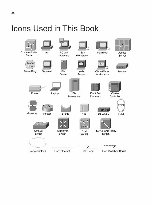
Icons Used in This Book
PC PC withSoftware
SunWorkstation
Macintosh
Terminal File Server
WebServer
Cisco WorksWorkstation
Printer Laptop IBMMainframe
Front EndProcessor
ClusterController
Modem
DSU/CSU
Router Bridge Hub DSU/CSU
CatalystSwitch
MultilayerSwitch
ATMSwitch
ISDN/Frame RelaySwitch
CommunicationServer
Gateway
AccessServer
Network Cloud
TokenRing
Token Ring
Line: Ethernet
FDDI
FDDI
Line: Serial Line: Switched Serial
xxi
Command Syntax ConventionsThe conventions used to present command syntax in this book are the same conventions used in the Cisco IOS Command Reference. The Command Reference describes these conventions as follows:
• Boldface indicates commands and keywords that are entered literally as shown. In actual configuration examples and output (not general command syntax), boldface indicates commands that are input manually by the user (such as a show command).
• Italics indicates arguments for which you supply actual values.
• Vertical bars (|) separate alternative, mutually exclusive elements.
• Square brackets [ ] indicate optional elements.
• Braces { } indicate a required choice.
• Braces within brackets [{ }] indicate a required choice within an optional element.
xxii
IntroductionQoS is a maturing technology, one that many networking professionals, to a greater or lesser extent, are already familiar with. This is both a blessing and a curse. It is a blessing because more administrators are enabling QoS on their networks, which allows for the convergence of voice, video, and data onto a single IP network, among other business advantages. It is a curse because almost every individual with whom I’ve ever discussed QoS designs has a slightly different opinion on how QoS should be enabled.
The result often has led to confusing babble from the customer’s perspective, especially for customers seeking QoS design guidance for non-VoIP applications. For example, a customer might ask the local Cisco Systems engineer how best to enable QoS for networks and receive one answer. Later, the cus-tomer might attend an Executive Briefing session in San Jose and receive a different answer (even receiving multiple different answers within the same day from different presenters). Later, while attending a Networkers conference, the customer might be told something else entirely. Finally, when the customer gets home and picks up a Cisco Press book, he or she might get still another story. Confused and frus-trated, many customers decide to enable minimal QoS, if any, despite the touted benefits that they were sold on. Therefore, in my opinion, presenting such inconsistent recommendations is a major disservice to our customers and a considerable barrier to the widespread deployment of QoS.
The Cisco Technology Baseline committees were created to remedy the situation and help unify various technologies across Cisco products and platforms. To this end, a series of Technology Baselines were developed internally by our leading experts (many of whom likewise developed the related IETF RFCs and other standards) to which all Cisco products and features must conform. Additionally, these docu-ments provide uniform, strategic recommendations (that can be shared with customers) to help ensure that QoS recommendations are unified and consistent, for both enterprises and service providers. Spe-cific to QoS, the QoS Baseline strictly defines the Cisco strategic direction in QoS technologies from now into the foreseeable future.
Thus, a unique feature of this book is that it is the first Cisco Press publication to present design recom-mendations that are compliant with the QoS Baseline.
Another huge advantage of this publication is that it is one of the first documents to present a detailed, cohesive strategy that shows how QoS can extend beyond its traditional role (of prioritizing important applications) and be used to provide deferential services to DoS/worm-generated traffic, thus mitigating and containing the collateral damage caused by such attacks. This is a fresh perspective and context for a technology that many considered baked and done. Yet in such a role, the critical interdependency of Quality of Service, High-Availability, and Security technologies becomes manifest and holistically pro-motes the “Self-Defending Networks” business objective.
However, having a strategic direction and tactical approaches for QoS designs is only half the solution. An important motto that I like to emphasize is: “In theory, theory and practice are the same.” It’s one thing to make a design recommendation based on an assumption that something “should work.” It’s something completely different to make a design recommendation that has been verified in large-scale, complex lab scenarios, such as provided by one of the largest Cisco labs: the Enterprise Solutions Engineering testbeds in Research Triangle Park, North Carolina.
xxiii
Notwithstanding, it should be noted that designs presented in this book are not infallible. While all due diligence has been done to present working, tested configurations—including a rigorous technical reviewing process by some of the sharpest Cisco QoS engineers—hardware/software/platform-specific issues that didn’t surface during our tests may nonetheless exist, as may issues introduced in newer releases of hardware/software dating from our time of testing.
Furthermore, the recommendations presented in this book are not to be taken as commandments or dictates (“Thou shalt configure this or that”), but are simply best-practice design recommendations that are the result of extensive lab testing and customer deployments. They should be viewed as templates that can be modified and tweaked to customer-specific requirements. Following the 80/20 Pareto Rule, these design recommendations should be viewed as 80 percent of the solution, to which the remaining 20 percent is up to each customer to complete and tailor to their individual needs and constraints.
Here’s an analogy of how to view these design recommendations: Given a business objective (for exam-ple, to hammer a nail into a wall), you will have certain tools at your disposal—tools that may or may not be optimally suited to the task (let’s say, a hammer and a banana). Our lab testing presents the optimal tool to use for the given objective (normally, a hammer tests better than a banana, but you never know—I’ve seen some pretty funky frozen bananas that might do the trick). It’s still up to the customer to pick the tool that best suits their objectives, situations, and comfort levels. These recommendations are not mandates; they are simply suggestions based on extensive lab testing and customer deployments.
Who Should Read This Book?Some might ask, “Why should I read this book? Especially when I have AutoQoS?”
Certainly, AutoQoS-VoIP is an excellent tool for customers whose objective is enabling QoS for VoIP (only) on their campus and WAN infrastructures, and AutoQoS-Enterprise is a fine tool for enabling basic WAN-edge QoS for voice, video, and multiple classes of data. For customers who have basic QoS needs and don’t have the time or desire to learn or do more with QoS, AutoQoS is definitely the way to go.
However, it’s important to remember where AutoQoS came from. AutoQoS tools are the result of QoS design guides that Cisco Technical Marketing Engineers (including myself) put together based on large-scale lab testing. AutoQoS-VoIP is the product of our first “AVVID QoS Design Guide,” one of the most popular and most downloaded technical whitepapers ever produced within Cisco. AutoQoS-Enterprise is the result of the QoS Baseline coupled with our second-generation QoS Design Guide. This book rep-resents our third-generation QoS Design Guide. And it is the goal of the authors to drive these designs (including DoS/worm-mitigation strategies) into future releases of AutoQoS. So, basically, what you are reading is the proposed blueprint for the next version of AutoQoS.
When it comes to any given technology, there are really only two types of people: those who are inter-ested in the technology and seek a thorough understanding of the relation of the parts to the whole, and those who just want to “turn it on” and walk away. The former are the ones who will confidently unleash the true power of the technology and push it to its limits; the latter are the ones who are usually hesitant, timid, and conservative in their use of the technology, typically accompanied with mediocre results.
For example, there are those who enjoy looking under the hood of a Ferrari and want to know all the details about how the engine generates its beautiful purring and power, and there are others who want

xxiv
only to turn it on, drive away, and look sexy. The former group will drive more confidently, boldly unleashing the engine’s tremendous power and, thus, pushing the car to its limits.
This book is intended for the former type of QoS networking professional—those looking for a thorough understanding of what makes them move so fast, sound so good, and look so sexy as they confidently harness their technology.
Goals and MethodsThe main goal of this book is to present templates that address 80 percent or more of a customer’s requirement of QoS in a particular context and architecture (LAN, WAN, VPN). Additionally, the rationales and considerations behind the recommendations are explained in detail so that as tweaking is required, network administrators are well informed of the trade-offs involved.
A key approach that we’ve used throughout this configuration-rich book is to incorporate inline expla-nations of configurations. In this way, the QoS-relevant commands are highlighted and detailed line-by-line to illustrate the function of each element and how these parts make up the whole solution.
To complement these line-by-line design recommendations, related verification commands are detailed. These verification commands are presented in context with the design examples, and specific details of what to look for in the resulting output are highlighted. These verification examples are, therefore, sig-nificantly richer in relevance than most such examples presented in Cisco documentation, and they allow network administrators to confirm quickly whether the recommended designs have been deployed correctly.
Finally, each design chapter has a case-study example at the end that ties together many of the design elements presented in the chapter and presents a bigger-picture detailed example for the infrastructure architecture being discussed (LAN/WAN/VPN). These examples are indicative of what can be expected in production environments. Often these case-study examples span several devices and, thus, highlight critical interrelationships.
How This Book Is OrganizedThis book is divided into three main parts: an introduction and overview section, a QoS toolset review section, and (the heart of the book) a QoS design section.
• Chapter 1, “Introduction to QoS,” is an introduction and brief history of the development of QoS technologies, showing where these came from and the direction they’re headed in.
• Chapter 2, “QoS Design Overview,” is an overview of QoS design. It begins by detailing the service-level requirements of voice, video, and data applications, and it presents the Scavenger-class DoS/worm-mitigation strategy and high-level QoS best practices that will be detailed in the design chapters to follow.
To set proper context for the design chapters, various QoS tools are reviewed. This review is not indented to serve as feature documentation, but it supplements Cisco documentation to highlight various inter-dependancies or caveats for these tools that at times impact the recommended QoS designs that follow. The QoS toolset review section, Chapters 3 through 11, covers the following topics:
xxv
• Chapter 3, “Classification and Marking Tools”—This chapter reviews Layer 2 marking mechanisms (such as 802.1Q/p, Frame Relay Discard Eligibility, ATM Cell Loss Priority, and MPLS Experimental Values) and Layer 3 marking mechanisms (such as IP Precedence and Differentiated Services Code Points).
• Chapter 4, “Policing and Shaping Tools”—This chapter reviews the token bucket algorithm, which is the basis for most policers and shapers. Both two-rate and three-rate policers are covered as are ATM and Frame Relay traffic shaping.
• Chapter 5, “Congestion-Management Tools”—This chapter reviews the evolution of queuing mechanisms and focuses on Low-Latency Queuing and Class-Based Weighted Fair Queuing. This chapter highlights the interoperation and interdependencies of these mechanisms with other QoS mechanisms, such as link-fragmentation and shaping tools.
• Chapter 6, “Congestion-Avoidance Tools”—This chapter reviews the Weighted Random Early Detection mechanism and shows how this can be used to provide Differentiated Services within an (RFC 2597) Assured Forwarding traffic class. This chapter also shows how this mechanism can be used to set (RFC 3168) IP Explicit Congestion Notification bits.
• Chapter 7, “Link-Specific Tools”—This chapter reviews header-compression techniques (such as TCP and RTP header compression) and link-fragmentation and interleaving techniques (such as Multilink PPP Link Fragmentation and Interleaving [MLP LFI] and Frame Relay fragmentation [FRF.12]).
• Chapter 8, “Bandwidth Reservation”—This chapter reviews the Resource Reservation Protocol (RSVP) and shows how it can be applied to admission control and MPLS Traffic Engineering.
• Chapter 9, “Call Admission Control (CAC)”—This chapter reviews local, resource-based, and measurement-based call admission control (CAC) mechanisms, including the use of RSVP for CAC. The tools reviewed in previous chapters can protect voice from data, but only CAC tools can protect voice from voice.
• Chapter 10, “Catalyst QoS Tools”—This chapter reviews the main classification, marking, mapping, policing, and queuing tools available on the current Cisco Catalyst platforms (including the Catalyst 2950, 2970, 3550, 3560, 3570, 4500-Supervisors II+ to V, and Catalyst 6500 Supervisor 2 and Supervisor 720).
• Chapter 11, “WLAN QoS Tools”—This chapter reviews QoS mechanisms available for wireless access points, including the 802.11e Enhanced Distributed Coordination Function (EDCF) and the QoS Basic Service Set (QBSS).
When the QoS toolset is reviewed, the context is set for the detailed design recommendations that follow. The next chapters—which comprise the heart of this book—cover the QoS design recommenda-tions for protecting voice, video, and multiple classes of data while mitigating DoS/worm attacks for the following network infrastructure architectures:
• Chapter 12, “Campus QoS Design”—This design chapter details access, distribution, and core layer considerations and designs for Cisco Catalyst 2950, 2970, 3550, 3560, 3570, 4500-Supervisors III-V, and Catalyst 6500 Supervisor 2 and Supervisor 720 series switches. Five separate access-edge
xxvi
models are presented, along with detailed queuing/dropping recommendations on a per-platform basis. Platform-unique features, such as the Catalyst 3550 per-Port/per-VLAN policing feature, the Catalyst 6500 PFC2 Dual-Rate Policing feature, and the PFC3 Per-User Microflow Policing feature, are highlighted in context.
• Chapter 13, “WAN Aggregator QoS Design”—This design chapter details considerations and designs for low-speed (≤ 768 kbps), medium-speed (> 768 kbps and ≤ T1/E1), and high-speed (> T1/E1) private WAN topologies, such as leased lines, Frame Relay, ATM, ATM-to-Frame Relay service interworking, and ISDN.
• Chapter 14, “Branch Router QoS Design”—This design chapter details branch-specific considerations and designs, such as unidirectional applications, and branch-to-campus traffic classification through access lists and Network-Based Application Recognition (NBAR). Branch-specific designs include Cisco SAFE recommendations for using NBAR for known worm identification and policing.
• Chapter 15, “MPLS VPN QoS Design”—This design chapter details considerations and designs for both enterprises (that are mapping into MPLS VPN service-provider [edge] classes of service) and service providers (that are provisioning edge and core classes of service). Service provider designs also include details on how to provision MPLS DiffServ Tunneling Modes (Uniform, Short-Pipe, and Pipe) and an introduction to MPLS Traffic Engineering (demonstrating per-customer traffic engineering and per-customer/per-application traffic engineering through MPLS DiffServ Traffic Engineering).
• Chapter 16, “IPSec VPN QoS Design”—This design chapter details the considerations and designs for deploying site-to-site IPSec VPNs and for teleworker IPSec VPNs (which traverse broadband media, such as cable and DSL).
• Appendix, “At-a-Glance” QoS Summaries—Single-page summaries of key QoS concepts presented throughout this the book for ready-reference, including
— QoS Tools
— The Cisco QoS Baseline
— QoS Best Practices
— Scavenger-Class QoS Design
— Campus QoS Design
— WAN QoS Design
— Branch QoS Design
— MPLS VPN QoS Design (for Enterprise Subscribers)
— MPLS VPN QoS Design (for Service-Providers)
— IPSec VPN QoS Design

This page intentionally left blank


This chapter includes the following topics:
• Classification and marking
• Discussion of Layer 2 and Layer 3 marking fields and how these translate to each other
• Packet marking in different technologies, such as IP, MPLS, ATM, Frame Relay, and Ethernet
• Class-based classification and marking techniques and other mechanisms to achieve these results
C H A P T E R 3
Classification and Marking ToolsThe first step in defining a Quality-of-Service (QoS) policy is to identify the traffic that is to be treated differently (either preferentially or differentially). This is accomplished through classification and marking.
Although the terms classification and marking often are used interchangeably, the terms represent distinct and different actions that work together but also can be used independently.
• Classification tools sort packets into different traffic types, to which different policies then can be applied. The classification of packets normally occurs at each node in the network but is not required to be done everywhere. Classification of packets can happen without marking.
• Marking (or re-marking) typically establishes a trust boundary on which scheduling tools later depend. The network edge where markings are accepted (or rejected) is referred to as the trust-boundary. Marking also can be used in other locations in the network, as necessary, and is not always used solely for purposes of classification.
As with the general terms classification and marking, there is a difference in the action that the actual tools, named classifiers and markers, take on traffic.
• Classifiers—Inspect one or more fields in a packet to identify the type of traffic that the packet is carrying. After being identified, the traffic is directed to the applicable policy-enforcement mechanism for that traffic type, where it receives predefined treatment (either preferential or deferential). Such treatment can include marking and re-marking, queuing, policing, shaping, or any combination of these (and other) actions.
• Markers—Write a field within the packet, frame, cell, or label to preserve the classification decision that was reached at the trust boundary. By marking traffic at the trust boundary edge, subsequent nodes do not have to perform the same in-depth classification and analysis to determine how to treat the packet.
70 Chapter 3: Classification and Marking Tools
Classification ToolsClassification tools examine any of the following criteria to identify a flow and assign it for preferential or deferential treatment:
• Layer 1 (L1) parameters—Physical interface, subinterface, PVC, or port
• Layer 2 (L2) parameters—MAC address, 802.1Q/p class of service (CoS) bits, VLAN identification, experimental bits (MPLS EXP), ATM cell loss priority (CLP), and Frame Relay discard eligible (DE) bits
• Layer 3 (L3) parameters—IP Precedence, DiffServ code point (DSCP), source/destination IP address
• Layer 4 (L4) parameters—TCP or User Datagram Protocol (UDP) ports
• Layer 7 (L7) parameters—Application signatures and uniform resource locators (URLs) in packet headers or payload
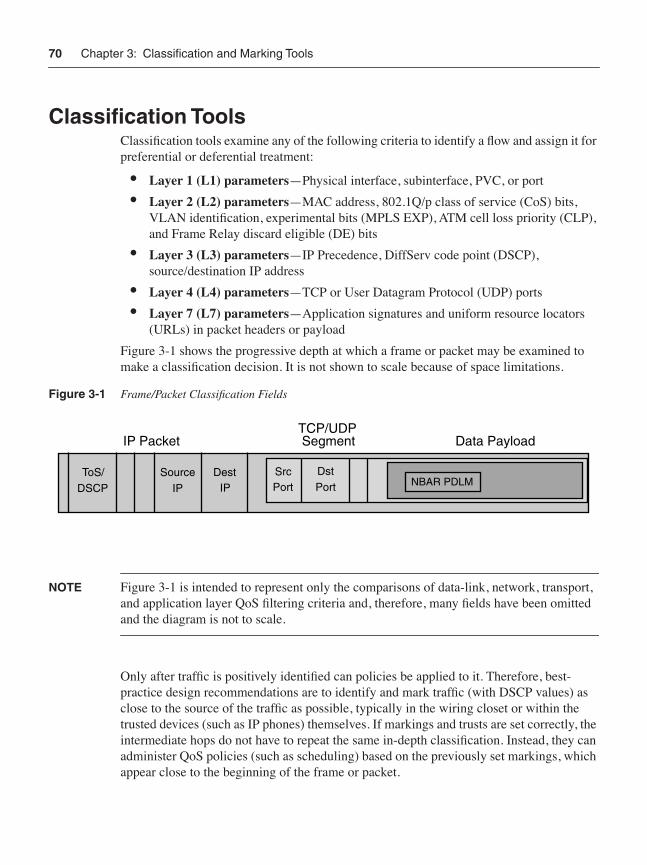
Figure 3-1 shows the progressive depth at which a frame or packet may be examined to make a classification decision. It is not shown to scale because of space limitations.
Figure 3-1 Frame/Packet Classification Fields
NOTE Figure 3-1 is intended to represent only the comparisons of data-link, network, transport, and application layer QoS filtering criteria and, therefore, many fields have been omitted and the diagram is not to scale.
Only after traffic is positively identified can policies be applied to it. Therefore, best-practice design recommendations are to identify and mark traffic (with DSCP values) as close to the source of the traffic as possible, typically in the wiring closet or within the trusted devices (such as IP phones) themselves. If markings and trusts are set correctly, the intermediate hops do not have to repeat the same in-depth classification. Instead, they can administer QoS policies (such as scheduling) based on the previously set markings, which appear close to the beginning of the frame or packet.
IP PacketTCP/UDPSegment Data Payload
SourceIP
DestIP
SrcPort
DstPort NBAR PDLM
ToS/DSCP
Classification Tools 71
Modular QoS Command-Line Interface Class MapsThe principle tool for QoS classification within Cisco IOS today is modular QoS CLI (MQC)–based class maps. Class maps identify traffic flows using a wide array of filtering criteria, which are individually defined by match statements within the class map. Multiple match statements can be defined under a single class map. When multiple match statements are used, the class map can be specified as follows:
• match-all—A logical AND operand, meaning that all match statements must be true at the same time for the class map condition to be true
• match-any—A logical OR operand, meaning that any of the match statements can be true for the class map condition to be true
Including match-any or match-all when defining a class map is optional, but it is impor-tant to note that if neither is specified, the default behavior is match-all. For example, if class-map FOO is entered, the Cisco IOS parser actually expands this to class-map match-all FOO within the configuration. Example 3-1 illustrates the matching criteria available within MQC class-maps.
Although the sequence in which class maps are defined within the configuration is unimportant, the sequence of classes within a policy map is important. This is because, as with access list (ACL) logic, policy maps apply the First-True-Match rule, meaning that the classes examine a packet until a match is found. When a match is found, the classification process finishes and no further class maps are checked. If no matches are found, the packet ends up in an implicit class default, which essentially means “everything else.”
For example, consider the service policy shown in Example 3-2 that illustrates the classifi-cation of two classes of traffic: VOICE for voice traffic and FAX-RELAY for fax traffic. The sequence of class-map FAX-RELAY and class-map VOICE within the global con-figuration does not matter to the classification functionality; these can be entered in any order. The assumption in this example is that both voice traffic and fax-relay traffic are
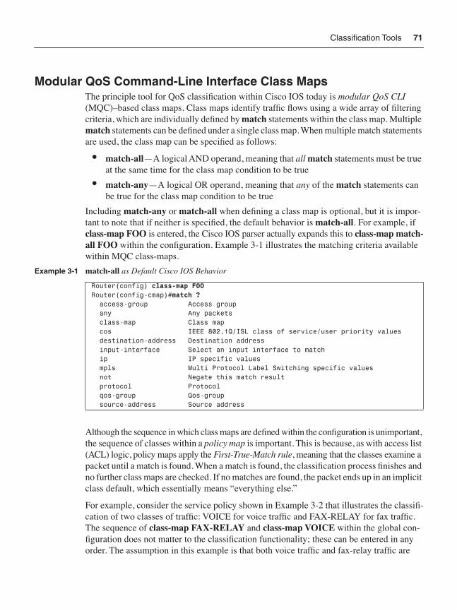
Example 3-1 match-all as Default Cisco IOS Behavior
Router(config) class-map FOORouter(config-cmap)#match ? access-group Access group any Any packets class-map Class map cos IEEE 802.1Q/ISL class of service/user priority values destination-address Destination address input-interface Select an input interface to match ip IP specific values mpls Multi Protocol Label Switching specific values not Negate this match result protocol Protocol qos-group Qos-group source-address Source address
72 Chapter 3: Classification and Marking Tools
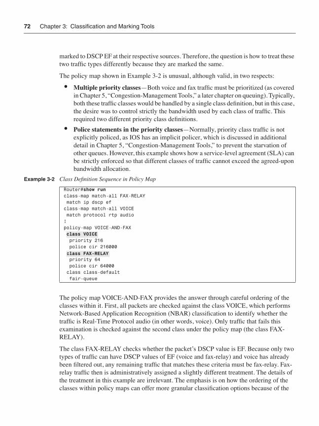
marked to DSCP EF at their respective sources. Therefore, the question is how to treat these two traffic types differently because they are marked the same.
The policy map shown in Example 3-2 is unusual, although valid, in two respects:
• Multiple priority classes—Both voice and fax traffic must be prioritized (as covered in Chapter 5, “Congestion-Management Tools,” a later chapter on queuing). Typically, both these traffic classes would be handled by a single class definition, but in this case, the desire was to control strictly the bandwidth used by each class of traffic. This required two different priority class definitions.
• Police statements in the priority classes—Normally, priority class traffic is not explicitly policed, as IOS has an implicit policer, which is discussed in additional detail in Chapter 5, “Congestion-Management Tools,” to prevent the starvation of other queues. However, this example shows how a service-level agreement (SLA) can be strictly enforced so that different classes of traffic cannot exceed the agreed-upon bandwidth allocation.
The policy map VOICE-AND-FAX provides the answer through careful ordering of the classes within it. First, all packets are checked against the class VOICE, which performs Network-Based Application Recognition (NBAR) classification to identify whether the traffic is Real-Time Protocol audio (in other words, voice). Only traffic that fails this examination is checked against the second class under the policy map (the class FAX-RELAY).
The class FAX-RELAY checks whether the packet’s DSCP value is EF. Because only two types of traffic can have DSCP values of EF (voice and fax-relay) and voice has already been filtered out, any remaining traffic that matches these criteria must be fax-relay. Fax-relay traffic then is administratively assigned a slightly different treatment. The details of the treatment in this example are irrelevant. The emphasis is on how the ordering of the classes within policy maps can offer more granular classification options because of the
Example 3-2 Class Definition Sequence in Policy Map
Router#show runclass-map match-all FAX-RELAY match ip dscp efclass-map match-all VOICE match protocol rtp audio!policy-map VOICE-AND-FAX class VOICE priority 216 police cir 216000 class FAX-RELAY priority 64 police cir 64000 class class-default fair-queue
class VOICE
class FAX-RELAY
Classification Tools 73
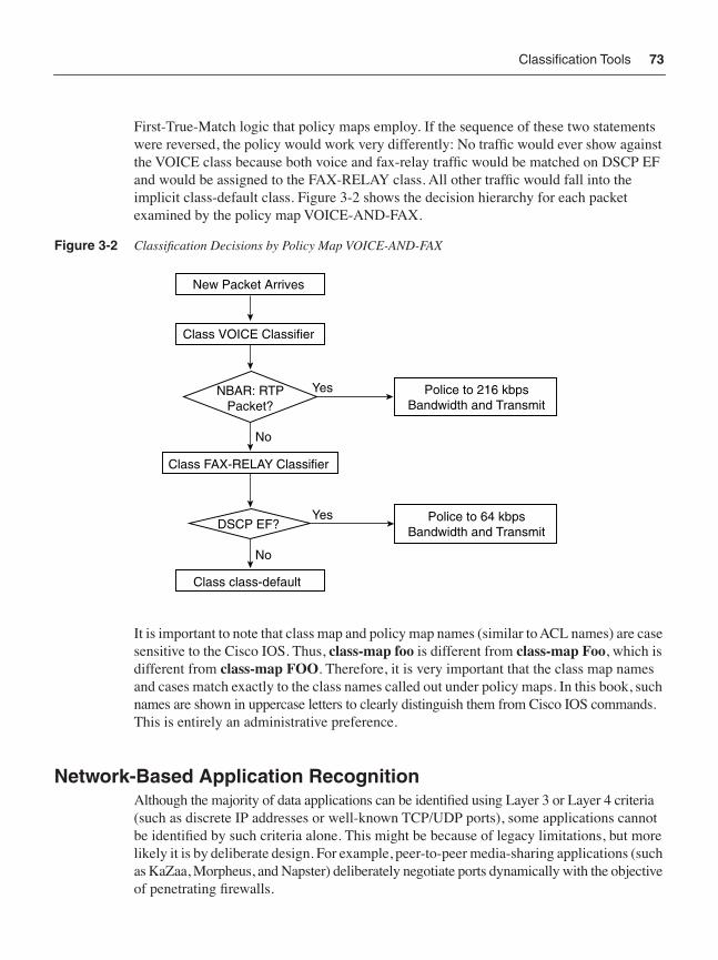
First-True-Match logic that policy maps employ. If the sequence of these two statements were reversed, the policy would work very differently: No traffic would ever show against the VOICE class because both voice and fax-relay traffic would be matched on DSCP EF and would be assigned to the FAX-RELAY class. All other traffic would fall into the implicit class-default class. Figure 3-2 shows the decision hierarchy for each packet examined by the policy map VOICE-AND-FAX.
Figure 3-2 Classification Decisions by Policy Map VOICE-AND-FAX
It is important to note that class map and policy map names (similar to ACL names) are case sensitive to the Cisco IOS. Thus, class-map foo is different from class-map Foo, which is different from class-map FOO. Therefore, it is very important that the class map names and cases match exactly to the class names called out under policy maps. In this book, such names are shown in uppercase letters to clearly distinguish them from Cisco IOS commands. This is entirely an administrative preference.
Network-Based Application RecognitionAlthough the majority of data applications can be identified using Layer 3 or Layer 4 criteria (such as discrete IP addresses or well-known TCP/UDP ports), some applications cannot be identified by such criteria alone. This might be because of legacy limitations, but more likely it is by deliberate design. For example, peer-to-peer media-sharing applications (such as KaZaa, Morpheus, and Napster) deliberately negotiate ports dynamically with the objective of penetrating firewalls.
New Packet Arrives
Class VOICE Classifier
NBAR: RTPPacket?
Police to 216 kbps Bandwidth and Transmit
DSCP EF?
Class FAX-RELAY Classifier
Class class-default
Police to 64 kbps Bandwidth and Transmit
Yes
No
Yes
No
74 Chapter 3: Classification and Marking Tools
When Layer 3 or 4 parameters are insufficient to positively identify an application, NBAR is a viable alternative solution.
NBAR is the most sophisticated classifier in the Cisco IOS tool suite. NBAR can recognize packets on a complex combination of fields and attributes. However, it is important to recognize that NBAR is merely a classifier, nothing more. NBAR can identify packets that belong to a certain traffic stream by performing deep-packet inspection, but it is up to the policy map to determine what should be done with these packets after they have been identified (in other words, whether they should be marked, policed, dropped, and so on).
NBAR’s deep-packet classification examines the data payload of stateless protocols and identifies application layer protocols by matching them against a Protocol Description Language Module (PDLM), which is essentially an application signature. Cisco IOS software supports 98 protocols via PDLMs as of IOS 12.3. Furthermore, because PDLMs are modular, they can be added to a system without requiring a Cisco IOS upgrade.
NBAR is dependent on Cisco Express Forwarding (CEF) and performs deep-packet classification only on the first packet of a packet stream. The remainder of the packets belonging to the stream then are CEF-switched. CEF is one of the packet-forwarding mechanisms within the Cisco IOS Software; there are also fast- and process-switching forwarding paths.
NOTE The NBAR classifier is triggered by the match protocol command within a class map definition. It is a more CPU-intensive classifier than classifiers that match traffic by DSCPs or ACLs.
NBAR Protocol ClassificationNBAR can classify packets based on Layer 4 through Layer 7 protocols, which dynamically assign TCP/UDP ports. By looking beyond the TCP/UDP port numbers of a packet (known as subport classification), NBAR examines the packet payload itself and classifies packets on the payload content, such as transaction identifiers, message types, or other similar data. For example, HTTP traffic can be classified by URLs or Multipurpose Internet Mail Extension (MIME) types using regular expressions within the CLI.
NBAR also can classify Citrix Independent Computing Architecture (ICA) traffic and can perform subport classification of Citrix traffic based on Citrix published applications. Requests from Citrix ICA clients can be monitored for a published application that is destined for a Citrix ICA master browser. After receiving the client requests to the published
Classification Tools 75
application, the Citrix ICA master browser directs the client to the server with the most available memory. The Citrix ICA client then connects to this Citrix ICA server for the application.
A summary of protocols that NBAR can use for classification follows. Because new capabilities are added all the time, this is not an exhaustive list. Not all NBAR classification involves stateful inspection, and not all match protocol commands trigger NBAR.
Statefully inspected protocols include the following:
Static protocols include the following:
FTP Oracle SQL*NETExchange SunRPCHTTP (URL and MIME) TFTPNetShow StreamWorksRealAudio VDOLiver-commands
Exterior Gateway Protocol (EGP) NNTPGeneric Routing Encapsulation (GRE) NotesICMP Network Time Protocol (NTP)IPinIP PCAnywhereIPSec POP3EIGRP Point-to-Point Tunneling Protocol (PPTP)BGP RIPCU-SeeMe Resource Reservation Protocol (RSVP)DHCP/BOOTP Secure FTP (SFTP)Domain Name System (DNS) SHTTPFinger SIMAPGopher SIRCHTTP SLDAPSecure HTTP (HTTP) SNNTPInternet Message Access Protocol (IMPA) SMTPInternet Relay Chat (IRC) SNMPKerberos SOCKSLayer 2 Tunnel Protocol (L2TP) SPOP3LDAP Secure Shell (SSH)MS-PPTP Secure Telnet (STELNET)MS-SQLServer SyslogNetBIOS TelnetNetwork File System (NFS) X Window System

76 Chapter 3: Classification and Marking Tools
Example 3-3 shows the CLI of some NBAR classification configurations.
Example 3-3 defines three different class maps. The first one, the class map ERP, instructs the classifier (NBAR) to pick traffic of any of the protocols listed in the subsequent statements, which include SQLNET, FTP, or Telnet traffic. In the class map AUDIO-VIDEO, the clas-sifier is looking for MIME traffic of particular types—audio and video, in this case. The last class map, WEB-IMAGES, is filtering out HTTP traffic for picture (GIF or JPEG) content.
In addition to classification, NBAR can perform protocol discovery using the sniffing capa-bilities of its classification engine. Even if NBAR is not required for QoS policy classifica-tion, its protocol-discovery mode can provide valuable information about traffic present on the network and how much bandwidth each traffic type is using. Such information can be used in bandwidth provisioning exercises or for capacity planning. An example output of NBAR’s protocol-discovery mode is shown in Example 3-4.
NBAR RTP Payload ClassificationStateful identification of real-time audio and video traffic can differentiate and classify traffic on the basis of audio and video codec fields within the Real-Time Transport Protocol (RTP) payload of the packet. Although most voice classification is done in coarser granularity
Example 3-3 NBAR Classification Examples
Router(config)# class-map match-any ERPRouter(config-cmap)# match protocol sqlnetRouter(config-cmap)# match protocol ftpRouter(config-cmap)# match protocol telnet
Router(config)# class-map match-any AUDIO-VIDEORouter(config-cmap)# match protocol http mime "*/audio/*"Router(config-cmap)# match protocol http mime "*/video/*" Router(config)# class-map match-any WEB-IMAGESRouter(config-cmap)# match protocol http url "*.gif"Router(config-cmap)# match protocol http url "*.jpg|*.jpeg"
Example 3-4 NBAR Protocol Discovery
Router#show ip nbar protocol-discovery stats byte-rate FastEthernet1/0
Input Output Protocol 30second bit rate 30second bit rate (bps) (bps) -------------- ------------------ ------------------ telnet 368000 0 ftp 163000 0 http 163000 0 unknown 614000 0 Total 1308000 0
Marking Tools 77
(by merely separating signaling traffic from speech path [media] traffic) and network access often is allowed or denied based on the originating port or IP address, sometimes traffic is desired to be classified by codec. One instance in which this is useful is at the trust boundary between an enterprise and a service provider network where the SLA is, for example, for G.729 and G.711 traffic only. In this instance, NBAR can be used to ensure that voice calls of other codecs are not allowed onto the network.
The same mechanisms can be used if codecs of different bandwidth needs must be filtered out, for example, to ensure that call admission control (CAC) in the network is not broken. In this case, low-bandwidth codecs such as G.729 and G.723 can be separated from G.711 traffic.
Filtering traffic by codec can be done by inspecting the payload type (PT) field within the RTP header, as defined by the following:
• RFC 1889: “RTP: A Transport Protocol for Real-Time Applications”
• RFC 1890: “RTP Profile for Audio and Video Conferences with Minimal Control”
The command to configure this is as follows:
match protocol rtp [audio | video | payload-type payload-string]
Here, the following is true:
• audio—Specifies matching by payload-type values 0 to 23
• video—Specifies matching by payload-type values 24 to 33
• payload-type—Specifies matching by payload-type value, for more granular matching
For example, the following command instructs NBAR to match RTP traffic with the payload types 0, 1, 4, 5, 6, 7, 8, 9, 10, 11, 12, 13, 14, 15, 16, 17, 18, or 64:
match protocol rtp payload-type "0, 1, 4 - 0x10, 10001b - 10010b, 64"
As shown in the example, the parameters to the match protocol statement can be given in decimal, hexadecimal (the 0x notation), or binary (the 10001b notation) numbers. Individual numbers separated by commas can be specified, and ranges of numbers can be used, as in the case of 4 – 0x10, which means a decimal value of 4 to a hexadecimal value of 10 (which equates to a decimal value of 16). Therefore, all RTP payload types between 4 and 16 are matched for this part of the statement. Similarly, the binary range 10001b to 10010b equates to 17 to 18 in decimal.
Marking ToolsThe main marking tools used today are class-based marking and marking using class-based policing. Some legacy marking techniques include committed access rate (CAR) and policy-based routing (PBR). Voice gateway packet marking is another option for IP telephony applications.

78 Chapter 3: Classification and Marking Tools
Class-Based MarkingClass-based marking, introduced in Cisco IOS Software Release 12.1(2)T, is an MQC-based syntax that uses the set command within a policy map to mark packets, frames, cells, or labels. Class-based marking was CEF dependent in early Cisco IOS releases (just after its introduction), but this limitation was listed in subsequent releases soon afterward. If you are using one of the initial releases, ip cef must be enabled in the global configuration before using set commands.
It is important to remember that class-based marking occurs after classification of the packet (in other words, set happens after the match criteria). Thus, if used on an output policy, the packet marking applied can be used by the next-hop node to classify the packet but cannot be used on this node for classification purposes. On the other hand, if class-based marking is used on an ingress interface as an input policy, the marking applied to the packet can be used on the same device on its egress interface for classification purposes.
Another point to note for output policies is that both classification and marking can happen after tunnel encapsulation, depending on where the service policy is attached. Therefore, if a policy is attached to a GRE or IPSec tunnel interface, the marking is applied to the original inner packet header. In most cases, this marking automatically is copied to the tunnel header. On the other hand, if the policy is attached to the physical interface, only the tunnel header (the outer header) is marked and the inner packet header is left unchanged.
As an alternative, QoS preclassification, discussed later in this chapter in the section titled “Layer 3 Tunnel Marking Tools,” can be used to ensure that classification of the packet happens on the inner packet header and not the tunnel header values.
Class-Based PolicingPolicing and other rate-limiting tools (which are discussed in more detail in Chapter 4, “Policing and Shaping Tools”) constitute one of the ways that packets can be marked. Instead of just marking every packet of a certain type as a particular value, a policer
Example 3-5 Class-Based Marking Options
Router(config)#policy-map CB-MARKINGRouter(config-pmap)#class FOORouter(config-pmap-c)#set ? atm-clp Set ATM CLP bit to 1 cos Set IEEE 802.1Q/ISL class of service/user priority discard-class Discard behavior identifier dscp Set DSCP in IP(v4) and IPv6 packets fr-de Set FR DE bit to 1 ip Set IP specific values mpls Set MPLS specific values precedence Set precedence in IP(v4) and IPv6 packets qos-group Set QoS Group
set ?

Marking Tools 79
generally can re-mark (or even drop) packets that violate an SLA. The following command shows the syntax for a rate-limiter that transmits packets if they conform to a specified rate, re-marks packets if they exceed the rate, and drops packets if they violate the rate.
police cir 1000000 bc 1000 pir 1000000 be 1000 conform-action transmit exceed-action set-clp-transmit violate-action drop
Class-based policing can set the IP Precedence, DSCP, MPLS EXP, Frame Relay DE, or ATM CLP of a packet based on rate-limiting measurements, as shown in Example 3-6.
Committed Access Rate As with class-based policing, committed access rate (CAR) can be used to set or change packet markings. However, CAR is an older Cisco IOS policer tool that generally is not integrated with the MQC syntax and can yield undesirable results if used in conjunction with service policies. Therefore, CAR is no longer a recommended policer.
Policy-Based Routing Policy-based routing (PBR) also is an older, non-MQC tool that can perform limited traffic marking. Although packet marking is not the major function of PBR, it can be used for writing IP Precedence for packets that match specific criteria.
Voice Gateway Packet MarkingFor voice traffic originating on a Cisco voice gateway router, H.323, Media Gateway Control Protocol (MGCP), and Session Initiation Protocol (SIP) traffic can be marked by the source gateway. For a long time, only IP Precedence marking was available for VoIP dial peers, and this only for media (voice) packets. In early releases, ACLs were required to mark call-signaling packets in conjunction with class-based marking.
Example 3-6 Re-Marking Options for the Class-Based Policer
Router(config)#policy-map CB-POLICINGRouter(config-pmap)#class FOOlab-2691(config-pmap-c)#police 8000 conform-action ? drop drop packet exceed-action action when rate is within conform and conform + exceed burst set-clp-transmit set atm clp and send it set-discard-class-transmit set discard-class and send it set-dscp-transmit set dscp and send it set-frde-transmit set FR DE and send it set-mpls-exp-imposition-transmit set exp at tag imposition and send it set-mpls-exp-topmost-transmit set exp on topmost label and send it set-prec-transmit rewrite packet precedence and send it set-qos-transmit set qos-group and send it transmit transmit packet
police conform-action ?

80 Chapter 3: Classification and Marking Tools
Cisco IOS Software Release 12.2(2)T introduced the capability to mark voice-sourced packets on the voice gateway with DSCPs, together with the capability to mark signaling packets separate from media packets and to mark voice traffic that did not use dial peers (such as MGCP). The following commands were introduced as part of the simplification of QoS. They are used for marking the voice traffic at its source, which is more efficient and easier to manage than manually marking such traffic on the nearest network edge.
H.323 and SIP use a VoIP dial peer command to mark signaling or media packets:
ip qos dscp [af11-af43 | cs1-cs7 | default | ef | num_0-63] [media | signaling]
MGCP uses a global gateway command to mark signaling or media packets:
mgcp ip-tos [rtp | signaling] precedence [0-7]mgcp ip qos dscp [af11-af43 | cs1-cs7 | default | ef | num_0-63] [media | signaling]
Another move toward simplification in Cisco IOS Software Release 12.2(2)T was to mark voice and call signaling by default with the appropriate DSCPs. This renders explicit marking unnecessary unless markings other than the recommended values are desired.
Voice gateway packet-marking features are detailed in Table 3-1.
Table 3-1 Voice Gateway Packet Marking Feature Summary by Cisco IOS Release
Cisco IOS Release Protocol QoS Marking Tools
IPP DSCP
DefaultMarking
Up to 12.1.5T and 12.2 mainline
SIP, H.323 Dial peer for media
PBR, ACL, CB marking for signaling
Yes Dial peer, PBR: No
CB marking: Yes
Media: 0
Signaling: 0
12.2.2T and later SIP, H.323 Dial peer for media and signaling marking
Yes Yes Media: 0
Signaling: 0
12.1.5XM and 12.2.2T and later
MGCP mgcp ip tos for media and signaling
Yes No Media: 5
Signaling: 3
12.2.11T and later
SIP, H.323 Dial peer for media and signaling marking
Yes Yes Media: 5, EF
Signaling: 3, AF31
12.2.11T and later
MGCP mgcp ip qos dscp for media and signaling
Yes Yes Media: 5, EF
Signaling: 3, AF31
Marking Tools 81
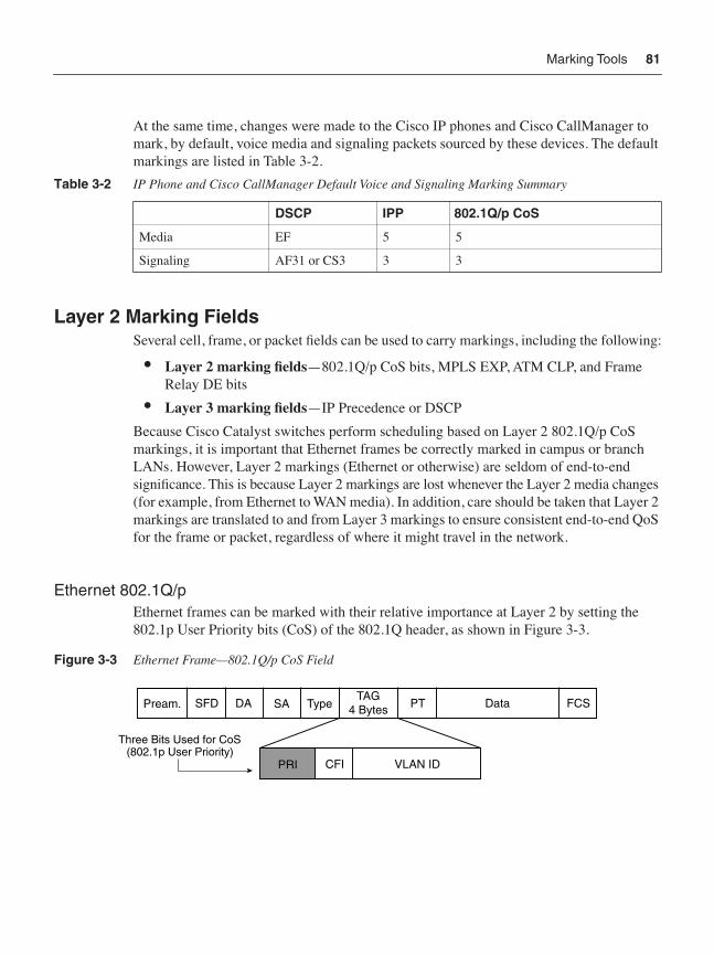
At the same time, changes were made to the Cisco IP phones and Cisco CallManager to mark, by default, voice media and signaling packets sourced by these devices. The default markings are listed in Table 3-2.
Layer 2 Marking FieldsSeveral cell, frame, or packet fields can be used to carry markings, including the following:
• Layer 2 marking fields—802.1Q/p CoS bits, MPLS EXP, ATM CLP, and Frame Relay DE bits
• Layer 3 marking fields—IP Precedence or DSCP
Because Cisco Catalyst switches perform scheduling based on Layer 2 802.1Q/p CoS markings, it is important that Ethernet frames be correctly marked in campus or branch LANs. However, Layer 2 markings (Ethernet or otherwise) are seldom of end-to-end significance. This is because Layer 2 markings are lost whenever the Layer 2 media changes (for example, from Ethernet to WAN media). In addition, care should be taken that Layer 2 markings are translated to and from Layer 3 markings to ensure consistent end-to-end QoS for the frame or packet, regardless of where it might travel in the network.
Ethernet 802.1Q/pEthernet frames can be marked with their relative importance at Layer 2 by setting the 802.1p User Priority bits (CoS) of the 802.1Q header, as shown in Figure 3-3.
Figure 3-3 Ethernet Frame—802.1Q/p CoS Field
Table 3-2 IP Phone and Cisco CallManager Default Voice and Signaling Marking Summary
DSCP IPP 802.1Q/p CoS
Media EF 5 5
Signaling AF31 or CS3 3 3
Three Bits Used for CoS(802.1p User Priority)
Pream. SFD DA SA TypeTAG
4 Bytes PT Data FCS
PRI CFI VLAN ID
82 Chapter 3: Classification and Marking Tools
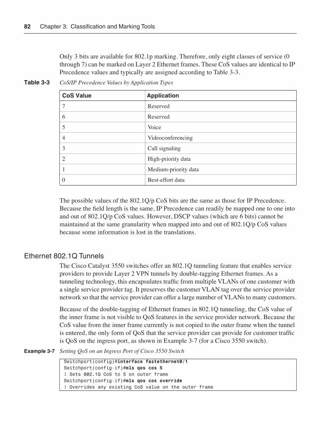
Only 3 bits are available for 802.1p marking. Therefore, only eight classes of service (0 through 7) can be marked on Layer 2 Ethernet frames. These CoS values are identical to IP Precedence values and typically are assigned according to Table 3-3.
The possible values of the 802.1Q/p CoS bits are the same as those for IP Precedence. Because the field length is the same, IP Precedence can readily be mapped one to one into and out of 802.1Q/p CoS values. However, DSCP values (which are 6 bits) cannot be maintained at the same granularity when mapped into and out of 802.1Q/p CoS values because some information is lost in the translations.
Ethernet 802.1Q TunnelsThe Cisco Catalyst 3550 switches offer an 802.1Q tunneling feature that enables service providers to provide Layer 2 VPN tunnels by double-tagging Ethernet frames. As a tunneling technology, this encapsulates traffic from multiple VLANs of one customer with a single service provider tag. It preserves the customer VLAN tag over the service provider network so that the service provider can offer a large number of VLANs to many customers.
Because of the double-tagging of Ethernet frames in 802.1Q tunneling, the CoS value of the inner frame is not visible to QoS features in the service provider network. Because the CoS value from the inner frame currently is not copied to the outer frame when the tunnel is entered, the only form of QoS that the service provider can provide for customer traffic is QoS on the ingress port, as shown in Example 3-7 (for a Cisco 3550 switch).
Table 3-3 CoS/IP Precedence Values by Application Types
CoS Value Application
7 Reserved
6 Reserved
5 Voice
4 Videoconferencing
3 Call signaling
2 High-priority data
1 Medium-priority data
0 Best-effort data
Example 3-7 Setting QoS on an Ingress Port of Cisco 3550 Switch
Switchport(config)#interface fastethernet0/1Switchport(config-if)#mls qos cos 5! Sets 802.1Q CoS to 5 on outer frameSwitchport(config-if)#mls qos cos override! Overrides any existing CoS value on the outer frame
Marking Tools 83
Layer 2 protocol packets can be given high priority by using the l2protocol-tunnel cos global command.
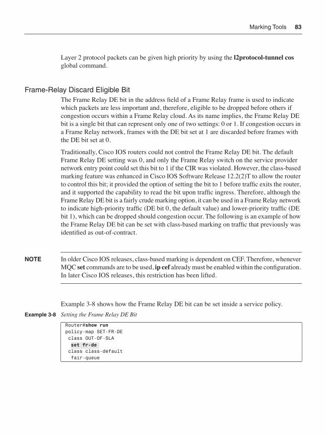
Frame-Relay Discard Eligible BitThe Frame Relay DE bit in the address field of a Frame Relay frame is used to indicate which packets are less important and, therefore, eligible to be dropped before others if congestion occurs within a Frame Relay cloud. As its name implies, the Frame Relay DE bit is a single bit that can represent only one of two settings: 0 or 1. If congestion occurs in a Frame Relay network, frames with the DE bit set at 1 are discarded before frames with the DE bit set at 0.
Traditionally, Cisco IOS routers could not control the Frame Relay DE bit. The default Frame Relay DE setting was 0, and only the Frame Relay switch on the service provider network entry point could set this bit to 1 if the CIR was violated. However, the class-based marking feature was enhanced in Cisco IOS Software Release 12.2(2)T to allow the router to control this bit; it provided the option of setting the bit to 1 before traffic exits the router, and it supported the capability to read the bit upon traffic ingress. Therefore, although the Frame Relay DE bit is a fairly crude marking option, it can be used in a Frame Relay network to indicate high-priority traffic (DE bit 0, the default value) and lower-priority traffic (DE bit 1), which can be dropped should congestion occur. The following is an example of how the Frame Relay DE bit can be set with class-based marking on traffic that previously was identified as out-of-contract.
NOTE In older Cisco IOS releases, class-based marking is dependent on CEF. Therefore, whenever MQC set commands are to be used, ip cef already must be enabled within the configuration. In later Cisco IOS releases, this restriction has been lifted.
Example 3-8 shows how the Frame Relay DE bit can be set inside a service policy.
Example 3-8 Setting the Frame Relay DE Bit
Router#show runpolicy-map SET-FR-DE class OUT-OF-SLA set fr-de class class-default fair-queue
set fr-de

84 Chapter 3: Classification and Marking Tools
ATM Cell-Loss Priority BitThe purpose of the ATM CLP bit is exactly the same as that of the Frame Relay DE bit. It is a binary field with two values: 0 (the default), which indicates higher-priority traffic, and 1, for cells carrying lower-priority traffic that is eligible to be dropped if congestion is encountered.
Although the capability to set the CLP bit has been available in a policy map since Cisco IOS Software Release 12.1.5T with the introduction of class-based marking, it is important to note that not all ATM interface drivers allow this capability. The Cisco 7200 ATM port adapters (PAs) have long had this capability. The Cisco 2600/3600/3700 ATM interfaces implemented this capability in Cisco IOS Software Release 12.2.1(1)T, and the digital sub-scriber line (DSL) interfaces (ADSL and G.SHDSL) require Cisco IOS Software Release 12.2.8YN or later to achieve this feature. Example 3-9 shows how the ATM CLP bit can be set with class-based marking on traffic that previously was identified as out-of-contract.
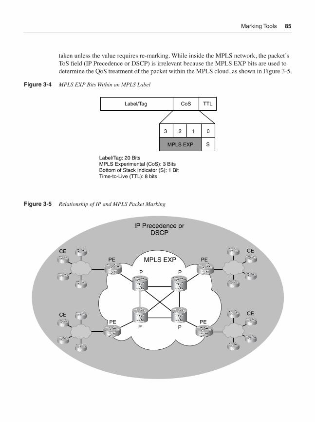
MPLS Experimental BitsMPLS is a tunneling technology that envelops an IP packet with an MPLS label that has its own field definitions for routing and QoS. More than one MPLS label can be used to envelop a packet. Typically, two labels are used in most MPLS VPN scenarios. In some scenarios, three labels are used. MPLS labels contain 3 bits for CoS marking. These bits are referred to as the MPLS EXP bits.
The possible values of the MPLS EXP bits for CoS are the same as those for 802.1Q/p CoS and IP Precedence. Because of the same length translations (3 bits to/from 6 bits) explained earlier for 802.1Q/p CoS, IP Precedence (which are 3 bits) readily can be mapped into and out of MPLS EXP values, but DSCP values (which are 6 bits) cannot be maintained at the same granularity. Figure 3-4 shows the MPLS EXP bits within an MPLS label.
As of Cisco IOS Software Release 12.1(5)T, the MPLS EXP bits can be read (match com-mand within a class map) and written (set command within a policy map) using MQC. When a packet enters the MPLS network at the provider edge (PE) router, the IP Precedence of the packet (by default) automatically is copied to the MPLS EXP field in the MPLS header. No explicit action is typically necessary to mark MPLS EXP values, unless the values require re-marking because of administrative policies.
In theory, upon exiting the MPLS network, the original IP packet re-emerges unchanged with its IP header type of service (ToS) field intact. Again, no explicit action needs to be
Example 3-9 Marking with ATM-CLP
Router# show runpolicy-map SET-ATM-CLP class OUT-OF-SLA set atm-clp class class-default fair-queue
set atm-clp
Marking Tools 85
taken unless the value requires re-marking. While inside the MPLS network, the packet’s ToS field (IP Precedence or DSCP) is irrelevant because the MPLS EXP bits are used to determine the QoS treatment of the packet within the MPLS cloud, as shown in Figure 3-5.
Figure 3-4 MPLS EXP Bits Within an MPLS Label
Figure 3-5 Relationship of IP and MPLS Packet Marking
Label/Tag CoS TTL
MPLS EXP S
3 2 1 0
Label/Tag: 20 BitsMPLS Experimental (CoS): 3 BitsBottom of Stack Indicator (S): 1 BitTime-to-Live (TTL): 8 bits
MPLS EXP
P
PE
PEPEP
PP
IP Precedence orDSCP
PE
CE
V
V
CE
V
V
CE
V
V
CE
V
V
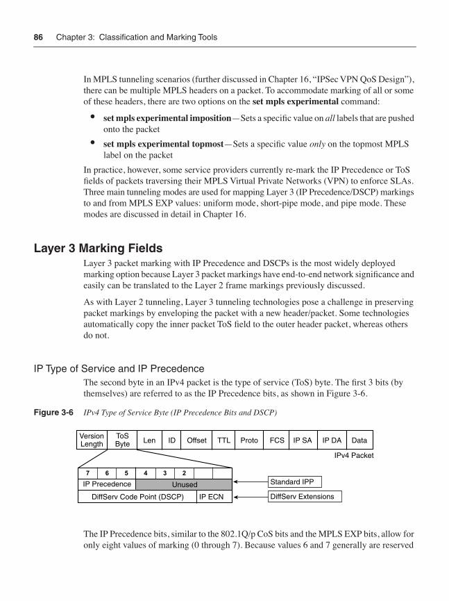
86 Chapter 3: Classification and Marking Tools
In MPLS tunneling scenarios (further discussed in Chapter 16, “IPSec VPN QoS Design”), there can be multiple MPLS headers on a packet. To accommodate marking of all or some of these headers, there are two options on the set mpls experimental command:
• set mpls experimental imposition—Sets a specific value on all labels that are pushed onto the packet
• set mpls experimental topmost—Sets a specific value only on the topmost MPLS label on the packet
In practice, however, some service providers currently re-mark the IP Precedence or ToS fields of packets traversing their MPLS Virtual Private Networks (VPN) to enforce SLAs. Three main tunneling modes are used for mapping Layer 3 (IP Precedence/DSCP) markings to and from MPLS EXP values: uniform mode, short-pipe mode, and pipe mode. These modes are discussed in detail in Chapter 16.
Layer 3 Marking FieldsLayer 3 packet marking with IP Precedence and DSCPs is the most widely deployed marking option because Layer 3 packet markings have end-to-end network significance and easily can be translated to the Layer 2 frame markings previously discussed.
As with Layer 2 tunneling, Layer 3 tunneling technologies pose a challenge in preserving packet markings by enveloping the packet with a new header/packet. Some technologies automatically copy the inner packet ToS field to the outer header packet, whereas others do not.
IP Type of Service and IP PrecedenceThe second byte in an IPv4 packet is the type of service (ToS) byte. The first 3 bits (by themselves) are referred to as the IP Precedence bits, as shown in Figure 3-6.
Figure 3-6 IPv4 Type of Service Byte (IP Precedence Bits and DSCP)
The IP Precedence bits, similar to the 802.1Q/p CoS bits and the MPLS EXP bits, allow for only eight values of marking (0 through 7). Because values 6 and 7 generally are reserved
7 6 5 4 3 2 1 0
ID Offset TTL Proto FCS IP SA IP DA DataLenVersionLength
ToSByte
Standard IPv4Standard IPP
DiffServ ExtensionsDiffServ Extensions
IPv4 Packet
IP Precedence Unused
DiffServ Code Point (DSCP) IP ECN

Marking Tools 87
for network control traffic (such as routing) and value 0 is the default marking value, really only five remaining values can be used to differentiate non-best-effort traffic. Of these five remaining values, however, the following is true:
• IP Precedence value 5 is recommended for voice.
• IP Precedence value 4 is shared by videoconferencing and streaming video.
• IP Precedence value 3 is recommended for call signaling.
This leaves only two marking values (IP Precedence 1 and 2) available for all data application marking options. Thus, many enterprises find IP Precedence marking to be overly restrictive and favor instead the 6-bit/64-value DSCP marking model.
NOTE In this book, IP Precedence is viewed as a legacy technology, and all Layer 3 marking recommendations are based on DSCP only (unless specific constraints exist).
Differentiated Services Code PointsAs shown in Figure 3-6, DSCPs use the same 3 bits as IP Precedence and combine these with the next 3 bits of the ToS byte to provide a 6-bit field for QoS marking. Thus, DSCP values range from 0 (000000) to 63 (111111). This range provides unprecedented richness in marking granularity.
DSCP values can be expressed in numeric form or by special keyword names, called per-hop behaviors (PHB). Three defined classes of DSCP PHBs exist: Best-Effort (BE or DSCP 0), Assured Forwarding (AFxy), and Expedited Forwarding (EF). In addition to these three defined PHBs, Class-Selector (CSx) codepoints have been defined to be backward compatible with IP Precedence (in other words, CS1 through CS7 are identical to IP Precedence values 1 through 7). The RFCs describing these PHBs are 2547, 2597, and 3246.
RFC 2597 defines four Assured Forwarding classes, denoted by the letters AF followed by two digits. The first digit denotes the AF class and can range from 1 through 4. (Incidentally, these values correspond to the three most significant bits of the codepoint, or the IPP value that the codepoint falls under.) The second digit refers to the level of drop preference within each AF class and can range from 1 (lowest drop preference) to 3 (highest drop preference). For example, during periods of congestion (on an RFC 2597–compliant node), AF33 would be dropped more often (statistically) than AF32, which, in turn, would be dropped more often (statistically) than AF31. Figure 3-7 shows the Assured Forwarding PHB encoding scheme.

88 Chapter 3: Classification and Marking Tools
Figure 3-7 DiffServ Assured Forwarding PHB Encoding Scheme
Figure 3-8 shows a summary of PHBs along with their decimal and binary equivalents.
Figure 3-8 DiffServ PHBs with Decimal and Binary Equivalents
Layer 3 Tunnel Marking ToolsCisco routers offer a variety of tunneling features, such as GRE, IPSec, and L2TP, which enable service providers to provide Layer 3 VPN tunnels by enveloping one IP packet within another. Such encapsulation masks the original header information to provide features such as privacy, encryption, and address preservation. Tunneling technologies also are used to carry non-IP protocols over an IP backbone.
X X X Y Y 0
DSCP
AFxy
Class Drop Precedence
IP Header ToS Byte
EF
Best Effort
AF11
AF21
AF31
AF41
AF12 AF13
AF22 AF23
AF32 AF33
AF42 AF43
Expedited Forwarding
Assured Forwarding
Per-Hop Behaviors (PHB) DiffServ Code Points
(DSCP)
101110
001010 001100 001110
010010 010100 010110
011010 011100 011110
100010 100100 100110
Class 1
Class 2
Class 3
Class 4
Low Drop Pref
Med Drop Pref
High Drop Pref
000000
46
10 12 14
18 20 22
26 28 30
34 36 38
0
BE

Marking Tools 89
A wide range of packet header layouts with tunneling technologies exist, but the primary characteristic that they have in common is that the original IP header is enveloped in an outer header packet. While in the tunnel, only the outer IP header’s ToS byte is examined to determine what QoS policies should be applied to the packet. The ToS byte from the inner packet might or might not be copied automatically to the outer header packet. If it is not copied automatically, explicit commands are required to copy the ToS byte (or to set the outer header ToS byte, independent of the inner packet’s ToS values).
Some example packet header layouts of GRE and IPSec packets are shown in Figure 3-9.
Figure 3-9 L3 Tunnel Packet Layout Examples
Three methods provide QoS marking for Layer 3 tunnels: QoS preclassification (QoS for VPNs feature), ToS copying/reflection, and independent header-packet marking. Each is discussed in more detail in the following sections.
QoS PreclassifyThe QoS preclassify feature was introduced in Cisco IOS Software Release 12.1(5)T on Cisco 7100 and 7200 series routers and in Cisco IOS Software Release 12.2(2)T for lower-end routers. This command creates a clone of the inner packet header (strictly for internal router processing) before the packet is enveloped. Upon egress, the router compares the cloned header against any policies applied to the egress interface (because it no longer can read information from the original packet header because it is enveloped). Then the appli-cable policies are serviced on the packet flow, and the clone is discarded. An advantage of the QoS preclassify feature is that not only is the ToS byte of the inner header used for QoS classification purposes, but other IP/TCP/UDP header parameters such as source/destina-tion IP addresses and source/destination ports can be used.
IPSec ESP Tunnel Mode
IPSec ESP Transport Mode
IPSecHdr
ESPHdr
ESPIV
GREIP
Hdr UDP RTP VoiceESP
Pad/NHESPAuth
IPSecHdr
ESPHdr
ESPIV
GREIP
Hdr UDP RTP VoiceESP
Pad/NHESPAuth
GRE IPHdr
GRE Tunneling
GREIP
Hdr UDP RTP Voice

90 Chapter 3: Classification and Marking Tools
Strictly speaking, the QoS preclassify feature is only a classification feature. Its marking functionality is only transient, in the sense that it makes a copy of the inner packet header and its markings, but this header never is transmitted as part of the packet.
Examples of the qos pre-classification command for various types of tunnels are shown in Example 3-10.
ToS ReflectionQoS marking for tunnels also can be achieved by copying the ToS byte from the inner header to the outer header. This is done by default on most platforms for IPSec and GRE tunnels. For L2TP, the l2tp tos reflect command can be used.
Independent Header-Packet MarkingAnother option is to mark the tunnel header explicitly as any other packet would be marked. This might be the least useful of the tunnel-marking methods because the characteristics for QoS treatment almost always are associated with the inner packet. Nevertheless, it is possible to mark the tunnel header independently with IP Precedence or DSCPs.
Translating Layer 2 and Layer 3 Packet MarkingsThe Layer 2 and Layer 3 marking fields discussed in the previous sections are summarized in Table 3-4.
It is important to remember that several technologies change packet headers or wrap one packet into another outer packet so that one packet or frame becomes the payload of the next. When this happens, packet marking is lost unless it explicitly is carried forward to the new packet (or frame) header. These repacketization changes occur when a data segment crosses a Layer 3 or Layer 2 technology boundary or when tunneling technologies are used. To preserve packet markings end to end, there is often the need to translate one type of marking to another at a network boundary (for example, LAN to WAN edge) or technology boundary (for example, the start of an encryption tunnel between two sites).
Example 3-10 QoS Preclassification Examples
GRE and IPIP TunnelsRouter(config)# interface tunnel0Router(config-if)# qos pre-classify
L2F and L2TP Tunnels:Router(config)# interface virtual-template1Router(config-if)# qos pre-classify
IPsec Tunnels:Router(config)# crypto map secured-partner-XRouter(config-crypto-map)# qos pre-classify
qos pre-classify
qos pre-classify
qos pre-classify
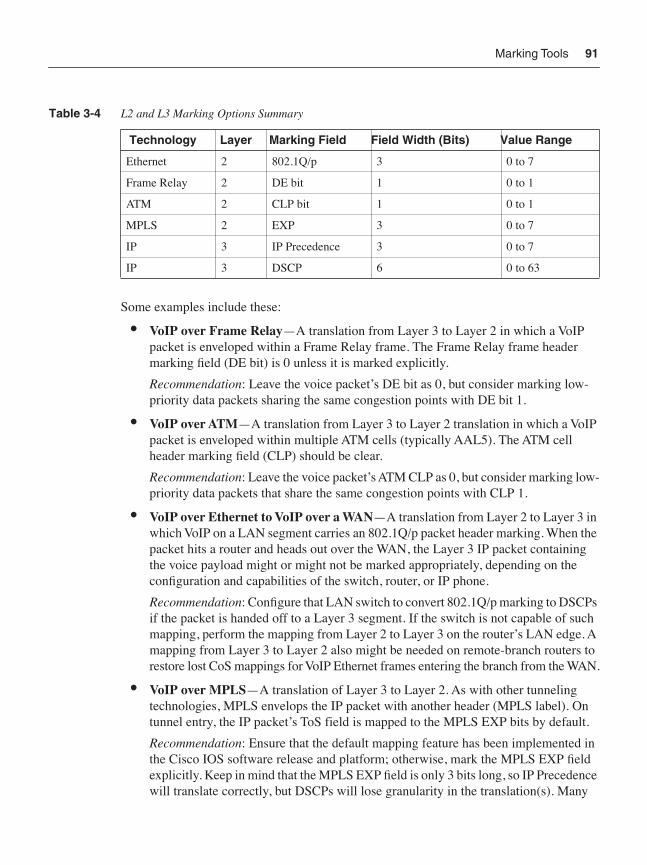
Marking Tools 91
Some examples include these:
• VoIP over Frame Relay—A translation from Layer 3 to Layer 2 in which a VoIP packet is enveloped within a Frame Relay frame. The Frame Relay frame header marking field (DE bit) is 0 unless it is marked explicitly.
Recommendation: Leave the voice packet’s DE bit as 0, but consider marking low-priority data packets sharing the same congestion points with DE bit 1.
• VoIP over ATM—A translation from Layer 3 to Layer 2 translation in which a VoIP packet is enveloped within multiple ATM cells (typically AAL5). The ATM cell header marking field (CLP) should be clear.
Recommendation: Leave the voice packet’s ATM CLP as 0, but consider marking low-priority data packets that share the same congestion points with CLP 1.
• VoIP over Ethernet to VoIP over a WAN—A translation from Layer 2 to Layer 3 in which VoIP on a LAN segment carries an 802.1Q/p packet header marking. When the packet hits a router and heads out over the WAN, the Layer 3 IP packet containing the voice payload might or might not be marked appropriately, depending on the configuration and capabilities of the switch, router, or IP phone.
Recommendation: Configure that LAN switch to convert 802.1Q/p marking to DSCPs if the packet is handed off to a Layer 3 segment. If the switch is not capable of such mapping, perform the mapping from Layer 2 to Layer 3 on the router’s LAN edge. A mapping from Layer 3 to Layer 2 also might be needed on remote-branch routers to restore lost CoS mappings for VoIP Ethernet frames entering the branch from the WAN.
• VoIP over MPLS—A translation of Layer 3 to Layer 2. As with other tunneling technologies, MPLS envelops the IP packet with another header (MPLS label). On tunnel entry, the IP packet’s ToS field is mapped to the MPLS EXP bits by default.
Recommendation: Ensure that the default mapping feature has been implemented in the Cisco IOS software release and platform; otherwise, mark the MPLS EXP field explicitly. Keep in mind that the MPLS EXP field is only 3 bits long, so IP Precedence will translate correctly, but DSCPs will lose granularity in the translation(s). Many
Table 3-4 L2 and L3 Marking Options Summary
Technology Layer Marking Field Field Width (Bits) Value Range
Ethernet 2 802.1Q/p 3 0 to 7
Frame Relay 2 DE bit 1 0 to 1
ATM 2 CLP bit 1 0 to 1
MPLS 2 EXP 3 0 to 7
IP 3 IP Precedence 3 0 to 7
IP 3 DSCP 6 0 to 63
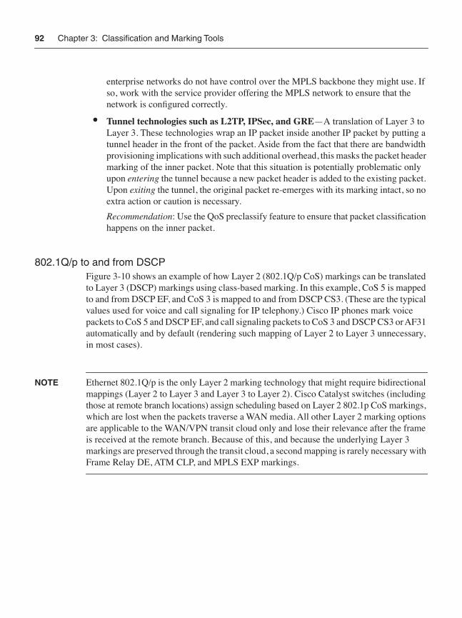
92 Chapter 3: Classification and Marking Tools
enterprise networks do not have control over the MPLS backbone they might use. If so, work with the service provider offering the MPLS network to ensure that the network is configured correctly.
• Tunnel technologies such as L2TP, IPSec, and GRE—A translation of Layer 3 to Layer 3. These technologies wrap an IP packet inside another IP packet by putting a tunnel header in the front of the packet. Aside from the fact that there are bandwidth provisioning implications with such additional overhead, this masks the packet header marking of the inner packet. Note that this situation is potentially problematic only upon entering the tunnel because a new packet header is added to the existing packet. Upon exiting the tunnel, the original packet re-emerges with its marking intact, so no extra action or caution is necessary.
Recommendation: Use the QoS preclassify feature to ensure that packet classification happens on the inner packet.
802.1Q/p to and from DSCPFigure 3-10 shows an example of how Layer 2 (802.1Q/p CoS) markings can be translated to Layer 3 (DSCP) markings using class-based marking. In this example, CoS 5 is mapped to and from DSCP EF, and CoS 3 is mapped to and from DSCP CS3. (These are the typical values used for voice and call signaling for IP telephony.) Cisco IP phones mark voice packets to CoS 5 and DSCP EF, and call signaling packets to CoS 3 and DSCP CS3 or AF31 automatically and by default (rendering such mapping of Layer 2 to Layer 3 unnecessary, in most cases).
NOTE Ethernet 802.1Q/p is the only Layer 2 marking technology that might require bidirectional mappings (Layer 2 to Layer 3 and Layer 3 to Layer 2). Cisco Catalyst switches (including those at remote branch locations) assign scheduling based on Layer 2 802.1p CoS markings, which are lost when the packets traverse a WAN media. All other Layer 2 marking options are applicable to the WAN/VPN transit cloud only and lose their relevance after the frame is received at the remote branch. Because of this, and because the underlying Layer 3 markings are preserved through the transit cloud, a second mapping is rarely necessary with Frame Relay DE, ATM CLP, and MPLS EXP markings.
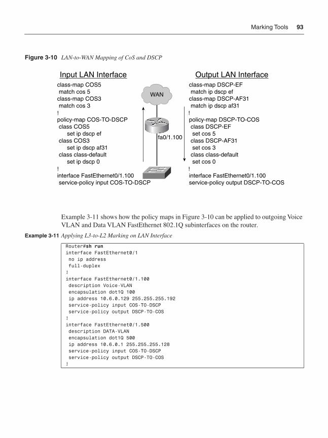
Marking Tools 93
Figure 3-10 LAN-to-WAN Mapping of CoS and DSCP
Example 3-11 shows how the policy maps in Figure 3-10 can be applied to outgoing Voice VLAN and Data VLAN FastEthernet 802.1Q subinterfaces on the router.
Example 3-11 Applying L3-to-L2 Marking on LAN Interface
Router#sh runinterface FastEthernet0/1 no ip address full-duplex!interface FastEthernet0/1.100 description Voice-VLAN encapsulation dot1Q 100 ip address 10.6.0.129 255.255.255.192 service-policy input COS-TO-DSCP service-policy output DSCP-TO-COS!interface FastEthernet0/1.500 description DATA-VLAN encapsulation dot1Q 500 ip address 10.6.0.1 255.255.255.128 service-policy input COS-TO-DSCP service-policy output DSCP-TO-COS!
class-map COS5 match cos 5
class-map COS3 match cos 3
policy-map COS-TO-DSCPclass COS5
set ip dscp ef class COS3
set ip dscp af31 class class-default
set ip dscp 0
interface FastEthernet0/1.100 service-policy input COS-TO-DSCP
class-map DSCP-EF match ip dscp ef
class-map DSCP-AF31 match ip dscp af31
policy-map DSCP-TO-COSclass DSCP-EF set cos 5
class DSCP-AF31 set cos 3 class class-default set cos 0
interface FastEthernet0/1.100 service-policy output DSCP-TO-COS
Input LAN Interface Output LAN Interface
fa0/1.100
WAN
!
!
!
!
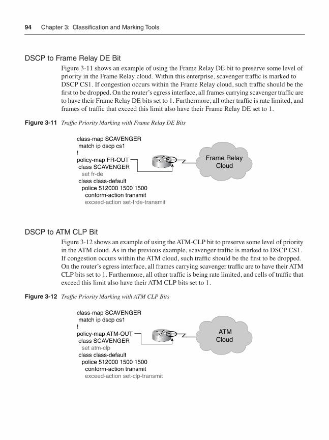
94 Chapter 3: Classification and Marking Tools
DSCP to Frame Relay DE BitFigure 3-11 shows an example of using the Frame Relay DE bit to preserve some level of priority in the Frame Relay cloud. Within this enterprise, scavenger traffic is marked to DSCP CS1. If congestion occurs within the Frame Relay cloud, such traffic should be the first to be dropped. On the router’s egress interface, all frames carrying scavenger traffic are to have their Frame Relay DE bits set to 1. Furthermore, all other traffic is rate limited, and frames of traffic that exceed this limit also have their Frame Relay DE set to 1.
Figure 3-11 Traffic Priority Marking with Frame Relay DE Bits
DSCP to ATM CLP BitFigure 3-12 shows an example of using the ATM-CLP bit to preserve some level of priority in the ATM cloud. As in the previous example, scavenger traffic is marked to DSCP CS1. If congestion occurs within the ATM cloud, such traffic should be the first to be dropped. On the router’s egress interface, all frames carrying scavenger traffic are to have their ATM CLP bits set to 1. Furthermore, all other traffic is being rate limited, and cells of traffic that exceed this limit also have their ATM CLP bits set to 1.
Figure 3-12 Traffic Priority Marking with ATM CLP Bits
class-map SCAVENGER match ip dscp cs1
!policy-map FR-OUT class SCAVENGER
set fr-de class class-default police 512000 1500 1500
conform-action transmit exceed-action set-frde-transmit
Frame RelayCloud
class-map SCAVENGER match ip dscp cs1
!policy-map ATM-OUT class SCAVENGER
set atm-clp class class-default police 512000 1500 1500
conform-action transmit exceed-action set-clp-transmit
ATMCloud
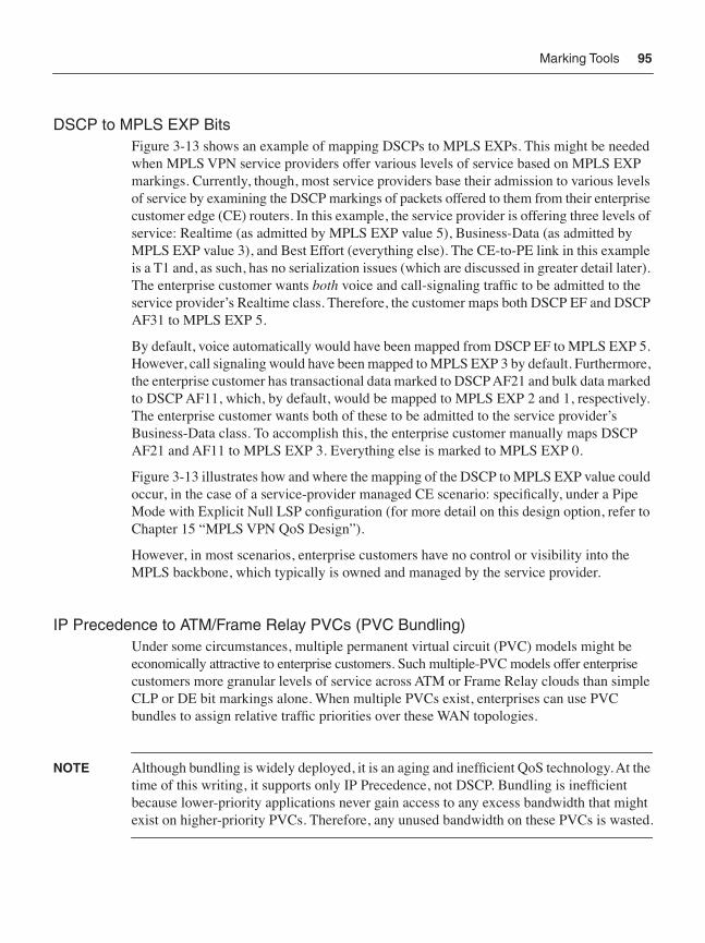
Marking Tools 95
DSCP to MPLS EXP BitsFigure 3-13 shows an example of mapping DSCPs to MPLS EXPs. This might be needed when MPLS VPN service providers offer various levels of service based on MPLS EXP markings. Currently, though, most service providers base their admission to various levels of service by examining the DSCP markings of packets offered to them from their enterprise customer edge (CE) routers. In this example, the service provider is offering three levels of service: Realtime (as admitted by MPLS EXP value 5), Business-Data (as admitted by MPLS EXP value 3), and Best Effort (everything else). The CE-to-PE link in this example is a T1 and, as such, has no serialization issues (which are discussed in greater detail later). The enterprise customer wants both voice and call-signaling traffic to be admitted to the service provider’s Realtime class. Therefore, the customer maps both DSCP EF and DSCP AF31 to MPLS EXP 5.
By default, voice automatically would have been mapped from DSCP EF to MPLS EXP 5. However, call signaling would have been mapped to MPLS EXP 3 by default. Furthermore, the enterprise customer has transactional data marked to DSCP AF21 and bulk data marked to DSCP AF11, which, by default, would be mapped to MPLS EXP 2 and 1, respectively. The enterprise customer wants both of these to be admitted to the service provider’s Business-Data class. To accomplish this, the enterprise customer manually maps DSCP AF21 and AF11 to MPLS EXP 3. Everything else is marked to MPLS EXP 0.
Figure 3-13 illustrates how and where the mapping of the DSCP to MPLS EXP value could occur, in the case of a service-provider managed CE scenario: specifically, under a Pipe Mode with Explicit Null LSP configuration (for more detail on this design option, refer to Chapter 15 “MPLS VPN QoS Design”).
However, in most scenarios, enterprise customers have no control or visibility into the MPLS backbone, which typically is owned and managed by the service provider.
IP Precedence to ATM/Frame Relay PVCs (PVC Bundling)Under some circumstances, multiple permanent virtual circuit (PVC) models might be economically attractive to enterprise customers. Such multiple-PVC models offer enterprise customers more granular levels of service across ATM or Frame Relay clouds than simple CLP or DE bit markings alone. When multiple PVCs exist, enterprises can use PVC bundles to assign relative traffic priorities over these WAN topologies.
NOTE Although bundling is widely deployed, it is an aging and inefficient QoS technology. At the time of this writing, it supports only IP Precedence, not DSCP. Bundling is inefficient because lower-priority applications never gain access to any excess bandwidth that might exist on higher-priority PVCs. Therefore, any unused bandwidth on these PVCs is wasted.
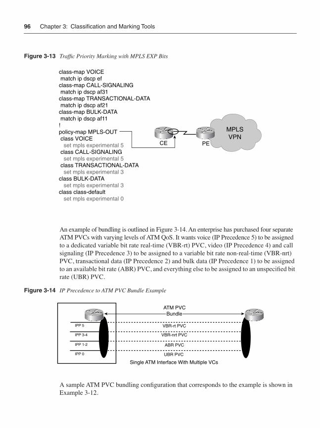
96 Chapter 3: Classification and Marking Tools
Figure 3-13 Traffic Priority Marking with MPLS EXP Bits
An example of bundling is outlined in Figure 3-14. An enterprise has purchased four separate ATM PVCs with varying levels of ATM QoS. It wants voice (IP Precedence 5) to be assigned to a dedicated variable bit rate real-time (VBR-rt) PVC, video (IP Precedence 4) and call signaling (IP Precedence 3) to be assigned to a variable bit rate non-real-time (VBR-nrt) PVC, transactional data (IP Precedence 2) and bulk data (IP Precedence 1) to be assigned to an available bit rate (ABR) PVC, and everything else to be assigned to an unspecified bit rate (UBR) PVC.
Figure 3-14 IP Precedence to ATM PVC Bundle Example
A sample ATM PVC bundling configuration that corresponds to the example is shown in Example 3-12.
MPLSVPN
class-map VOICE match ip dscp efclass-map CALL-SIGNALING match ip dscp af31class-map TRANSACTIONAL-DATA match ip dscp af21class-map BULK-DATA match ip dscp af11!policy-map MPLS-OUT class VOICE set mpls experimental 5 class CALL-SIGNALING set mpls experimental 5 class TRANSACTIONAL-DATA set mpls experimental 3class BULK-DATA set mpls experimental 3 class class-default set mpls experimental 0
CE PE
Single ATM Interface With Multiple VCs
ATM PVCBundle
IPP 0
VBR-rt PVC
IPP 1-2
IPP 3-4
IPP 5
VBR-nrt PVC
ABR PVC
UBR PVC
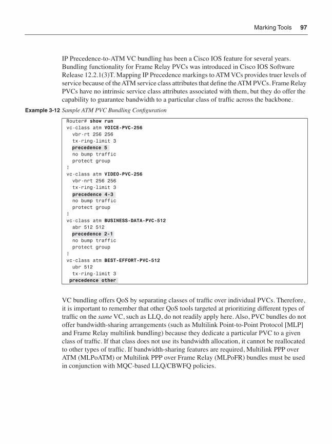
Marking Tools 97
IP Precedence-to-ATM VC bundling has been a Cisco IOS feature for several years. Bundling functionality for Frame Relay PVCs was introduced in Cisco IOS Software Release 12.2.1(3)T. Mapping IP Precedence markings to ATM VCs provides truer levels of service because of the ATM service class attributes that define the ATM PVCs. Frame Relay PVCs have no intrinsic service class attributes associated with them, but they do offer the capability to guarantee bandwidth to a particular class of traffic across the backbone.
VC bundling offers QoS by separating classes of traffic over individual PVCs. Therefore, it is important to remember that other QoS tools targeted at prioritizing different types of traffic on the same VC, such as LLQ, do not readily apply here. Also, PVC bundles do not offer bandwidth-sharing arrangements (such as Multilink Point-to-Point Protocol [MLP] and Frame Relay multilink bundling) because they dedicate a particular PVC to a given class of traffic. If that class does not use its bandwidth allocation, it cannot be reallocated to other types of traffic. If bandwidth-sharing features are required, Multilink PPP over ATM (MLPoATM) or Multilink PPP over Frame Relay (MLPoFR) bundles must be used in conjunction with MQC-based LLQ/CBWFQ policies.
Example 3-12 Sample ATM PVC Bundling Configuration
Router# show runvc-class atm VOICE-PVC-256 vbr-rt 256 256 tx-ring-limit 3 precedence 5 no bump traffic protect group!vc-class atm VIDEO-PVC-256 vbr-nrt 256 256 tx-ring-limit 3 precedence 4-3 no bump traffic protect group!vc-class atm BUSINESS-DATA-PVC-512 abr 512 512 precedence 2-1 no bump traffic protect group!vc-class atm BEST-EFFORT-PVC-512 ubr 512 tx-ring-limit 3 precedence other
precedence 5
precedence 4-3
precedence 2-1
precedence other
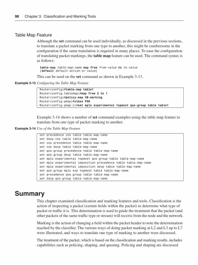
98 Chapter 3: Classification and Marking Tools
Table Map FeatureAlthough the set command can be used individually, as discussed in the previous sections, to translate a packet marking from one type to another, this might be cumbersome in the configuration if the same translation is required in many places. To ease the configuration of translating packet markings, the table map feature can be used. The command syntax is as follows:
table-map table-map-name map from from-value to to-value [default default-action-or-value]
This can be used on the set command as shown in Example 3-13.
Example 3-14 shows a number of set command examples using the table map feature to translate from one type of packet marking to another.
SummaryThis chapter examined classification and marking features and tools. Classification is the action of inspecting a packet (certain fields within the packet) to determine what type of packet or traffic it is. This determination is used to guide the treatment that the packet (and other packets of the same traffic type or stream) will receive from the node and the network.
Marking is the action of changing a field within the packet header to note the determination reached by the classifier. The various ways of doing packet marking at L2 and L3 up to L7 were illustrated, and ways to translate one type of marking to another were discussed.
The treatment of the packet, which is based on the classification and marking results, includes capabilities such as policing, shaping, and queuing. Policing and shaping are discussed
Example 3-13 Configuring the Table Map Feature
Router(config)#table-map table1 Router(config-tablemap)#map from 2 to 1Router(config)#policy-map CB-markingRouter(config-pmap)#class FOORouter(config-pmap-c)#set mpls experimental topmost qos-group table table1
Example 3-14 Use of the Table Map Feature
set precedence cos table table-map-nameset dscp cos table table-map-nameset cos precedence table table-map-nameset cos dscp table table-map-nameset qos-group precedence table table-map-nameset qos-group dscp table table-map-nameset mpls experimental topmost qos-group table table-map-nameset mpls experimental imposition precedence table table-map-nameset mpls experimental imposition dscp table table-map-nameset qos-group mpls exp topmost table table-map-nameset precedence qos-group table table-map-nameset dscp qos-group table table-map-name
Further Reading 99
in Chapter 4, “Policing and Shaping Tools,” and queuing is discussed in Chapter 5, “Congestion-Management Tools.”
Further Reading
General• Class-based marking: http://www.cisco.com/univercd/cc/td/doc/product/software/
ios122/122cgcr/fqos_c/fqcprt1/qcfcbmrk.htm.
• Class-based policing (Cisco IOS Software Release 12.2.2T): http://www.cisco.com/univercd/cc/td/doc/product/software/ios122/122cgcr/fqos_c/fqcprt4/qcfpoli.htm.
• Frame Relay DE bit marking (Cisco IOS Software Release 12.2.2T): http://www.cisco.com/univercd/cc/td/doc/product/software/ios121/121newft/121t/121t5/cbpmark2.htm#1037921.
• Enhanced packet marking (Cisco IOS Software Release 12.2.1[3]T): http://www.cisco.com/univercd/cc/td/doc/product/software/ios122/122newft/122t/122t13/ftenpkmk.htm.
• Packet classification based on Layer 3 packet length (Cisco IOS Software Release 12.2.13T): http://www.cisco.com/univercd/cc/td/doc/product/software/ios122/122newft/122t/122t13/ftmchpkt.htm.
• Packet classification using the Frame Relay DLCI number (Cisco IOS Software Release 12.2.13T): http://www.cisco.com/univercd/cc/td/doc/product/software/ios122/122newft/122t/122t13/ftpcdlci.htm.
DiffServ• DiffServ for end-to-end quality of service (Cisco IOS Software Release 12.1.5T):
http://www.cisco.com/univercd/cc/td/doc/product/software/ios121/121newft/121t/121t5/dtdfsv.htm.
• Classifying VoIP signaling and media with DSCP for QoS (Cisco IOS Software Release 12.2.2T): http://www.cisco.com/univercd/cc/td/doc/product/software/ios122/122newft/122t/122t2/ft_dscp.htm.
• Control plane DSCP support for RSVP (Cisco IOS Software Release 12.2.2T):http://www.cisco.com/univercd/cc/td/doc/product/software/ios122/122newft/122t/122t2/dscprsvp.htm.
• Voice Gateway Packet Marking (Cisco IOS Software Release 12.2.2T): http://www.cisco.com/univercd/cc/td/doc/product/software/ios122/122newft/122t/122t2/ft_dscp.htm.

100 Chapter 3: Classification and Marking Tools
L2 Protocol Tunneling• Catalyst 3550 IOS (Cisco IOS Software Release 12.1.14EA1) documentation:
http://www.cisco.com/univercd/cc/td/doc/product/lan/c3550/12114ea1/3550scg/swtunnel.htm.
• Catalyst 3550 802.1Q Tunneling Configuration Guide: http://wwwin.cisco.com/eag/dsbu/solutions/documents/06_802.1Q%20Tunneling%20Config%20Guide.doc.
• L2TP IP ToS reflect command IOS (Cisco IOS Software Release 12.3) documentation:http://www.cisco.com/univercd/cc/td/doc/product/software/ios123/123cgcr/dial_r/dia_l1g.htm#1131064.
VPN• Quality of service for Virtual Private Networks (Cisco IOS Software Release 12.1.5T):
http://www.cisco.com/univercd/cc/td/doc/product/software/ios121/121newft/121t/121t5/dtqosvpn.htm.
• Quality of service for Virtual Private Networks (Cisco IOS Software Release 12.2.2T):http://www.cisco.com/univercd/cc/td/doc/product/software/ios122/122newft/122t/122t2/ftqosvpn.htm.
NBAR• Network-Based Application Recognition and Distributed Network-Based Application
Recognition (Cisco IOS Software Release 12.1.5T): http://www.cisco.com/univercd/cc/td/doc/product/software/ios122/122newft/122t/122t8/dtnbarad.htm.
• NBAR RTP Payload Classification (Cisco IOS Software Release 12.2.8T):http://www.cisco.com/univercd/cc/td/doc/product/software/ios122/122newft/122t/122t8/dtnbarad.htm.
• Network-Based Application Recognition Protocol Discovery Management Information Base (Cisco IOS Software Release 12.2.1[5]T): http://www.cisco.com/univercd/cc/td/doc/product/software/ios122/122newft/122t/122t15/ftpdmib.htm.
MPLS• MPLS class of service enhancements (Cisco IOS Software Release 12.1.5T):
http://www.cisco.com/univercd/cc/td/doc/product/software/ios121/121newft/121t/121t5/mct1214t.htm.
• MPLS QoS multi-VC mode for PA-A3 (Cisco IOS Software Release 12.2.2T):http://www.cisco.com/univercd/cc/td/doc/product/software/ios122/122newft/122t/122t2/cos1221t.htm.
Further Reading 101
• DiffServ-aware MPLS traffic engineering (DS-TE) (Cisco IOS Software Release 12.2.4T): http://www.cisco.com/univercd/cc/td/doc/product/software/ios122/122newft/122t/122t4/ft_ds_te.htm.
• MPLS DiffServ-aware traffic engineering (DS-TE) over ATM (Cisco IOS Software Release 12.2.8T): http://www.cisco.com/univercd/cc/td/doc/product/software/ios122/122newft/122t/122t8/ft_ds_te.htm.
IP—ATM/Frame Relay Bundles• IP to ATM class of service (Cisco IOS Software Release 12.0.3T):
http://www.cisco.com/univercd/cc/td/doc/product/software/ios120/120newft/120t/120t3/ipatmcs2.htm.
• IP to ATM CoS, per VC WFQ and CBWFQ (Cisco IOS Software Release 12.0.5T):http://www.cisco.com/univercd/cc/td/doc/product/software/ios120/120newft/120t/120t5/ipatm3.htm.
• IP to ATM class of service mapping for SVC bundles (Cisco IOS Software Release 12.2.4T): http://www.cisco.com/univercd/cc/td/doc/product/software/ios122/122newft/122t/122t4/ftsvbund.htm.
• MPLS EXP to ATM VC bundling (Cisco IOS Software Release 12.2.8T):http://www.cisco.com/univercd/cc/td/doc/product/software/ios122/122newft/122t/122t8/ftmpls.htm.
• Frame Relay PVC bundles with QoS support for IP and MPLS (Cisco IOS Software Release 12.2.13T): http://www.cisco.com/univercd/cc/td/doc/product/software/ios122/122newft/122t/122t13/ft_frbnd.htm.
• MPLS EXP to Frame Relay VC bundling (Cisco IOS Software Release 12.2.13T):http://www.cisco.com/univercd/cc/td/doc/product/software/ios122/122newft/122t/122t13/ft_frbnd.htm.
Level 2 to Level 3 Packet-Marking Translation• Enhanced packet marking (Cisco IOS Software Release 12.2.1[3]T):
http://www.cisco.com/univercd/cc/td/doc/product/software/ios122/122newft/122t/122t13/ftenpkmk.htm.

I N D E X
Numerics10-Class WAN Edge Model, 5151P2Q1T queuing and dropping, 401–4041P2Q2T queuing and dropping, 405–4081P3Q1T mode, 3221P3Q1T queuing and dropping, 408–4101P3Q8T queuing and dropping, 411–4141P7Q8T queuing and dropping, 415–4181PxQyT queuing, 362Q2T queuing and dropping, 396-398
show qos info config 2q2 tx verification command, 398
show qos info runtime verification command, 399–400
show queuing interface verification command, 400
33 percent limit (sum of LLQs), 4504Q1T mode, 322802.11e, 275–277802.1D, classes of service, 279802.1Q/p, translating to and from DSCP, 92–93
Aaccess control entries (ACEs), 225access layer
Catalyst 3550 QoS design, 325policers, 54
access point (AP), 271access switches
configuring to conditionally trust CoS, 319access switches (campus networks), 291access-edge QoS design, 290access-edge trust boundaries, 302
Conditionally Trusted Endpoint Models, 303, 307–312
Trusted Endpoint Models, 302–304Untrusted Endpoint Models, 304–307
access-edge utilization, 293ACEs (access control entries), 225ACLs, MQC-based class maps, 233adaptive jitter buffers, 36admission control, 197
admission criterion (Real-Time class), 563–565ADSL (Asynchronous Digital Subscriber Lines),
672aggregate policers (Catalyst 6500), 258aggregation routers, 505–507algorithms
MDRR, 585queuing, 133
CBWFQ, 140comparison, 138PQ-WFQ, 139priority queuing, 137WFQ, 137
shaping, 120token bucket algorithms, 105
analog gateways, 303Anti-Replay drops, 638, 656Anti-Replay functionality (IPSec QoS design),
654-656any-to-any videoconferencing, 548–549AP (access point), 271applications
data applications by class, 46–47Mission-Critical Data, 43Streaming-Video, 41unidirectional, 513
architectures (MPLS VPNs). See MPLS VPN-QoS design
Assured Forwarding, 16asymmetric links, 677Asynchronous Digital Subscriber Lines (ADSL),
672ATM, 176
PVC bundles, 147Tx-rings, 489WAN edge link-specific QoS design
ATM-FR SIW, 497–501high-speed links, 494–495medium-speed links, 493slow-speed links, 488–493very-high-speed links, 496–497
ATM CLP (ATM Cell-Loss Priority bit), 84ATM inverse multiplexing over ATM, 493ATM networks, 121–122ATM PVC bundles, slow-speed, 490–492
714
ATM-FR SIW (ATM-to-Frame Relay Service Interworking), 497–498
slow-speed links, 499–501attacks (worms), 50-54authentication
ESP, 654IPSec, 657
AutoQoS (Automatic QoS), 24–25Enterprise feature, 25–26evolution of, 28
Bbackbone, 583–587bandwidth
Catalyst 4500, 251Eight-Class Model, 461guarantees, 137, 565ISDN, 501provisioning, 143, 645
Best-Effort class, 449Real-Time class, 449teleworker V3PN QoS, 674–677WAN aggregators, 449VoIP, 646
reservations, 195RSVP, 196–197statements, on class default, 457VoIP streams, 36–38
Bc (committed burst), 105, 479Be (excess burst), 110, 480bearer traffic
jitter, 36–38latency, 34–35loss, 34
Best-Effort classbandwidth provisioning, 449enabling WRED, 457
Best-Effort data, 44best-effort networks, 11best-effort service, 15binary eponential backoff, 274branch router QoS design, 513
case study, 535–540LAN edge, 517
branch-to-campus classification and marking, 519–525
DSCP-to-CoS remapping, 518NBAR known worm classification and
policing, 526–535WAN edge, 514–515
branch-to-branch traffic, 548branch-to-campus classification and marking,
519–521NBAR application classification, 523–525source or destination IP address marking, 520TCP/UDP classification, 522
broadbandserialization mitigation through TCP maximum
segment size tuning, 678–679split tunneling, 679–681UDP-based video applications, 678
broadband-access technologies, 671cable, 673DSL, 672
buffer space, 135buffers, 36–38Bulk Data class, 44
Ccable, 671-673
DOCSIS 1.1 specification, 678Integrated Unit + Access Models, 684–685overhead, 676–677uplink connections, 677
CAC (call admision control), 205CallManager locations CAC, 209–211defined, 206GK CAC, 211local CAC tools, 208measurement-based CAC tools, 208prering CAC, 212resource-based CAC tools, 209RSVP, 212tool categories, 207VoIP CAC through RSVP, 215
Call-SignalingMPLS VPN CE QoS design considerations, 553campus QoS design, 295
Call-Signaling traffic, jitter, 38
ATM-FR SIW (ATM-to-Frame Relay Service Interworking)
715
CallManager environments, 296–301CallManager locations CAC, 209–211CallManager services, 295campus Catalyst switches, 24campus networks
oversubscription ratios, 291QoS design. See campus QoS designtraffic, 339underutilization, 290
campus QoS design, 289–290access switches, 291Call-Signaling, 295case study, 422–439Catalyst 2950
Conditionally Trusted IP Phone + PC Advanced Model, 322
Conditionally Trusted IP Phone + PC Basic Model, 319–320
queuing, 322–325Trusted Endpoint Model, 314–315Untrusted Multiapplication Server Model,
315–319Untrusted PC with SoftPhone Model, 315
Catalyst 2970/3750, 342–343Conditionally Trusted IP Phone + PC
Basic Model, 346–348enabling/disabling QoS, 343queuing/dropping, 351–356Trusted Endpoint Model, 343–346Unconditionally Trusted IP Phone + PC
Basic Model, 348–351Untrusted PC with SoftPhone Model, 344Untrusted Server Model, 345
Catalyst 3550, 325–327Conditionally Trusted IP Phone + PC
Advanced Model, 333–336Conditionally Trusted IP Phone + PC
Basic Model, 331–333queuing and dropping, 336–341Trusted Endpoint Model, 327Untrusted PC with SoftPhone Model,
327–329Untrusted Server Model, 330–331
Catalyst 4500, 357–358Conditionally Trusted IP Phone + PC
Advanced Model, 364–366
Conditionally Trusted IP Phone + PC Basic Model, 362–364
queuing, 366–370show qos dbl command, 370show qos interface command, 371–372show qos maps dscp tx-queue command,
370–371Trusted Endpoint Model, 359Untrusted PC with SoftPhone Model,
359–360Untrusted Server Model, 360–362
Catalyst 6500, 372, 3741P2Q1T queuing and dropping, 401–4041P2Q2T queuing and dropping, 405–4081P3Q1T queuing and dropping, 408–4101P3Q8T queuing and dropping, 411–4141P7Q8T queuing and dropping, 415–4182Q2T queuing and dropping, 396–400CatOS defaults/recommendations, 375Conditionally Trusted IP Phone + PC
Advanced Model, 387–391Conditionally Trusted IP Phone + PC
Basic Model, 386–387congestion avoidance, 384PFC3 distribution-layer Per-User
Microflow Policing, 419queuing/dropping, 391–396show port qos command, 376–377Trusted Endpoint Model, 375Untrusted PC with SoftPhone Model,
378–382Untrusted Server Model, 383–386
defining designs, 292DoS/worm mitigation, 292–294WAN aggregator/branch router handoff,
420–422campus-to-branch traffic, 548CAR (committed access rate), 79, 107–108case studies
branch router QoS design, 535–540campus QoS design, 422–439IPSec VPN QoS design, 686
telecommuter router, 694–695V3PN branch router design, 691–693VPN headend design, 687–689WAN aggregator QoS design, 689–690
case studies
716
MPLS VPN QoS design, 616CE routers, 617-619PE routers, 620–630P routers, 630–631
WAN aggregation router QoS design, 505–507Catalyst 2950, 314–315
classification, marking, and mapping, 233Conditionally Trusted IP Phone + PC Advanced
Model, 322Conditionally Trusted IP Phone + PC Basic
Model, 319CoS-to-DSCP map, 233DSCP-to-CoS map, 234policing and markdown, 234queuing, 235, 322–323
show wrr-queue bandwidth command, 324show wrr-queue cos-map command, 325
range keyword, 315Trusted Endpoint Model, 314–315Untrusted Multiapplication Server Model,
315–318show class-map and show policy-map
verification commands, 318show mls masks qos verification
command, 319show mls qos interface policers
verification command, 318Untrusted PC with SoftPhone Model, 315vs. Catalyst 3550, 231
Catalyst 2970, 242, 342–343classification, marking, and mapping, 243Conditionally Trusted IP Phone + PC Basic
Model, 346–348enabling/disabling QoS, 343policing and markdown, 244queuing/dropping, 244–246, 351–356Trusted Endpoint Model, 343–346Unconditionally Trusted IP Phone + PC Basic
Model, 348–351Untrusted PC with SoftPhone Model, 344Untrusted Server Model, 345
Catalyst 3550, 235, 325–327classification, marking, and mapping, 237Conditionally Trusted IP Phone + PC Advanced
Model, 333–336Conditionally Trusted IP Phone + PC Basic
Model, 331–333
DSCP mutation maps, 237policing and markdown, 238–239queuing and dropping, 240–241, 336–339
show mls qos interface buffers verification command, 340
show mls qos interface queuing verification command, 341
Trusted Endpoint Model, 327Untrusted PC with SoftPhone Model, 327–329Untrusted Server Model, 330–331
Catalyst 3750, 242, 342–343classification, marking, and mapping, 243Conditionally Trusted IP Phone + PC Advanced
Model, 348–351Conditionally Trusted IP Phone + PC Basic
Model, 347–348enabling/disabling QoS, 343policing and markdown, 244queuing/dropping, 244–246, 351–356Trusted Endpoint Model, 343–346Untrusted PC with SoftPhone Model, 344Untrusted Server Model, 345
Catalyst 4500, 247, 357–358classification, marking, and mapping, 248–249Conditionally Trusted IP Phone + PC Advanced
Model, 364–366Conditionally Trusted IP Phone + PC Basic
Model, 362–364DSCP-to-queue maps, 251enabling QoS, 248policing and markdown, 249–250queuing, 366–370queuing and dropping, 250–252show qos dbl command, 370show qos interface command, 371–372show qos maps dscp tx-queue command,
370–371Trusted Endpoint Model, 359Untrusted PC with SoftPhone Model, 359–360Untrusted Server Model, 360–362
Catalyst 6500, 252, 372, 374CatOS
1P2Q1T queuing and dropping, 401–4041P2Q2T queuing and dropping, 405–4081P3Q1T queuing and dropping, 408–4101P3Q8T queuing and dropping, 411–4141P7Q8T queuing and dropping, 415–418
case studies
717
2Q2T queuing and dropping, 396–400Conditionally Trusted IP Phone + PC
Advanced Model, 387–391Conditionally Trusted IP Phone + PC
Basic Model, 386–387congestion avoidance, 384defaults/recommendations, 375queuing/dropping, 391–396Trusted Endpoint Model, 375Untrusted PC with SoftPhone Model,
378–379, 381–382Untrusted PC with SoftPhone Model
Model, 379–382Untrusted Server Model, 383–386
classification, marking and mapping, 254–256enabling QoS, 254PFC QoS, 261PFC3 distribution-layer Per-User Microflow
Policing, 419policing and markdown, 257–259queuing and dropping, 259–263Supervisor 720, 253Trusted Endpoint Model
show port qos command, 376–377VLAN-based QoS, 254WRED-drop thresholds, 262
Catalyst 6500 configuring microflow policers, 257Catalyst QoS Models, 224
classification, 225policing, 227queuing, 228-230
CatOS defaults/recommendations, 375CBR (constraint-based routing), 603CBWFQ (Class-Based Weighted Fair Queuing),
133, 139–140CDP (Cisco Discover Protocol), 307CE bit, 163CE design, 556–563CE routers, MPLS VPN QoS design case study,
617-619CEF (Cisco Express Forwarding), 74Channel Utilization field, 278CIR (committed information rate), 105
Frame Relay networks, 479policing behavior based on percentages, 118
Cisco 12000 routerspriority command, 587queuing, 585
Cisco Discover Protocol (CDP), 307Cisco Express Forwarding (CEF), 74class default policing, 112class selectors, 16class-based Frame Relay traffic shaping, 123–124class-based marking, 77class-based policing, 79, 109
benefits, 109single-rate three-color marker/policer, 110–112two-rate three-color marker/policer, 112–113
class-based shaping, 126-127Class-Based Weighted Fair Queuing (CBWFQ), 133classes of service (802.1D), 279classification, 57, 68–69
branch-to-campus, 519Catalyst 2950, 233Catalyst 2970, 243Catalyst 3550, 237Catalyst 3750, 243Catalyst 4500, 248–249Catalyst 6500, 254–256Catalyst QoS models, 225NBAR application, 523–524source or destination IP addresses, 520TCP/UDP, 522tools, 70
MQC-based class maps, 71–72NBAR, 73–77
Code Red, 527codecs (frame-based), 34CodeRedv2, 528color-aware policing, 116–117color-blind policing, 117commands, 47–48
commit all command, 377dbl policy command, 367frame-relay fragment command, 481match protocol dlsw command, 48max-reserved-bandwidth, 559–563mls qos cos override interface command, 316ping vrf command, 601–602ppp multilink links minimum command, 504priority-queue out command, 240qos dbl command, 367qos map dscp to tx-queue command, 367show atm bundle command, 493show atm pvc command, 489show atm vc command, 492
commands
718
show class-map verification command, 318show controllers command, 451show frame-relay fragment command, 482show ima interface atm command, 495show ip access-list command, 521show ip bgp vpnv4 all command, 615show ip nbar map command, 525show ip rsvp interface command, 599show ip rsvp neighbor command, 599show mls masks qos verification command, 319show mls qos command, 358show mls qos interface buffers verification
command, 340show mls qos interface policers verification
command, 318show mls qos interface queuing verification
command, 341show mls qos interface statistics verification
command, 329show mls qos maps command, 356show mls qos maps dscp-output-q command,
356show mpls interface command, 600show mpls traffic-eng topology command,
614–615show mpls traffic-eng tunnels command, 601show mpls traffic-eng tunnels summary
command, 600show policy command, 456show policy interface command, 469show policy interface verification command,
329show policy-map verification command, 318show port qos commands, 376–377show ppp multilink command, 478show qos acl verification command, 380show qos command, 358show qos dbl command, 370show qos info config 2q2 tx verification
command, 398show qos info runtime verification command,
399–400show qos interface command, 371–372show qos maps dscp tx-queue command,
370–371show qos maps verification command, 379show qos policer verification command, 381
show qos statistics verification command, 382show queuing interface verification command,
400show wrr-queue bandwidth command, 324show wrr-queue cos-map command, 325trust-device command, 386tx-queue command, 367tx-ring-limit command, 490wrr-queue bandwidth command, 322wrr-queue cos-map command, 240wrr-queue dscp-map interface configuration
command, 339wrr-queue queue-limit command, 240wrr-queue queue-limit interface command, 338
show mls qos map, 320commit all command, 377committed access rate (CAR), 79, 107–108committed burst rate (Bc, 105, 479committed information rate. See CIRcompatibility (802.1D classes of service), 279compression
G.729 voice compression, 170hardware compression, 181
Conditionally Trusted Endpoint Models (Trust Boundaries), 303, 307–312
Conditionally Trusted IP Phone + PC Advanced Model, 322
Catalyst 2970/3750, 348–351Catalyst 3550, 333–336Catalyst 4500, 364–366Catalyst 6500, 387–391
Conditionally Trusted IP Phone + PC Basic Model, 319, 346–347
Catalyst 2970/3750, 346–348Catalyst 3550, 331–333Catalyst 4500, 362–364Catalyst 6500, 386–387
configuring1P2Q2T queuing, 4071P3Q1T queuing, 4101P3Q1T queuing model, 3371P3Q8T queuing, 4121P7Q8T queuing, 416–417Catalyst 2950 switches
Conditionally Trusted IP Phone + PC Advanced Model, 322
commands
719
Conditionally Trusted IP Phone + PC Basic Model, 319–320
queuing, 322–323Trusted Endpoint Model, 314–315Untrusted Multiapplication Server Model,
315–316, 318–319Untrusted PC with SoftPhone Model, 315
CoS-to-queue mapping (Catalyst 3550), 240cRTP for ATM links, 176DSCP mutation, 238FR-VATS, 125individual policer on Catalyst 4500, 250IPSec authentication, 657MCMP for an ISDN interface, 185microflow policing on Catalyst 6500, 257MLP LFI, 184MPLS DS-TE, 606–613MPLS per-VPN TE, 592–598PFC, 255policing, 234QoS on Cisco APs, 281queuing (Catalyst 2950), 235RSVP, 196SRR shaping and sharing weights on Catalyst
2970/3750, 246trust on Catalyst 6500, 255VLAN-based QoS on Catalyst 6500, 254WRED, 162
configuring WRED-drop thresholds, 262confirming traffic, 107congestion avoidance
Catalyst 6500, 384tools, 159
DSCP-based WRED, 162–163explicit congestion notification, 163RED, 160WRED, 161–162
congestion-management tools, 133converged networks, 135–136
connecting trusted endpoints, 304consistent QoS behavior, 453constraint-based routing (CBR), 603constricted channels, 159control plane QoS
IP routing, 48–49network management, 49
controlled load, 15, 197controlling traffic
branch-to-branch, 548campus-to-branch, 548
converged networkscongestion-management tools, 135–136QoS, 12–14
convergence, 449Core Best-Effort class, 584Core Critical Data class, 584core QoS considerations, 582
aggregate bandwidth overprovisioning, 583DiffServ in the backbone
platform specific considerations, 585–587Three-Class Provider-Core Model,
583–585MPLS traffic engineering, 587
basic, 588–590MPLS DS-TE, 603–615MPLS per-VPN TE, 591–602
Core Real-Time class, 584CoS values, assigning queues, 240CoS-to-DSCP maps
Catalyst 2950, 233Catalyst 6500, 256
control plane provisioning, 657CQ (custom queuing), 137cRTP (RTP header compression), 172
class-based header compression, 178–179configuring for ATM links, 176formats, 173
Cisco propriety format, 173IETF format, 174IPHC, 173
formats and encapsulation summary, 177–178incompatibility with IPSec, 643–644Layer 2 encapsulation protocol support, 175
ATM, 176Frame Relay, 176HDLC, 175PPP, 175
LLQ, 145policing and shaping, 180tunnels, 180
crypto engine, 651–652cTCP (TCP header compression), 171custom queuing (CQ), 137
custom queuing (CQ)

720
CWmax, 278, 282CWmin, 274, 278, 282
Ddata
applications by class, 46–47QoS, 42–43
Best-Effort data, 44DLSw+, 47–48locally defined Mission-Critical Data, 45Transactional Data/Interactive Data, 45
data frames (802.11), 272data VLANs (DVLANs), 314datagrams, 153data-link connection identifiers (DLCIs), 123data-link switching plus (DLSw+), 47–48DBL (dynamic buffer limiting), 366-367DCF (Distributed Coordination Function), 272
Interframe Spaces, 272random backoffs, 273
DDR (dial-on-demand routing), 503DDT (delay to dial tone), 38delay budgets (IPSec VPNs), 647delay to dial tone (DDT), 38delay variation, 13–14. See also jitterdeploying
IPSec VPNs via DMVPN, 646LFI tools, 450policers, 106QoS designs, 62Untrusted Server Model on Catalyst 2950, 315
designing QoSclassification and marking principles, 57deployment, 62DoS and worm mitigation principles, 61–62policing and markdown principles, 57–58queuing and dropping principles, 58–60
destination IP address classification, 520DHCP, translating to Frame Relay DE bit, 94dial-on-demand routing (DDR), 503Differentiated Services code points (DSCPs), 87DiffServ, 16
advantages of DiffServ model, 16deploying in backbone
platform specific considerations, 585–587
Three-Class Provider-Core Model, 583–585
DIFS, 272Digital Subscriber Line. See DSLdisabling
flow control, 327native DLSw+ ToS markings, 48QoS on Catalyst 2970/3750, 343
Discard class placeholder, 568Distributed Coordination Function (DCF), 272distributed platform frame relay links, 486-487distributed platform QoS, 453distributed traffic shaping (DTS), 128, 486Distributed-Platform/Consistent QoS Behavior QoS
Baseline Model, 465–466distribution layer, Catalyst 3550 QoS design, 325DLCIs (data-link connection identifiers), 123dlsw tos disable command, 48dlsw tos map command, 47DLSw+ (data-link switching plus), 47–48DMVPNS (Dynamic Multipoint Virtual Private
Networks), 646DOCSIS 1.1 specification, 674, 678dominating links (VoIP), 449DoS attacks
campus network mitigation strategies, 292–294mitigation principles, 61–62
downstream QoS, 271drop thresholds (Catalyst 2970 and 3750), 245dropping, 58–60
Anti-Replay, 656Catalyst 2970, 244–246Catalyst 3550, 240–241, 336–339Catalyst 3750, 244–246Catalyst 4500, 250–252Catalyst 6500, 259–263, 391–394
1P2Q1T queuing and dropping, 401–4041P2Q2T queuing and dropping, 405–4081P3Q1T queuing and dropping, 408–4101P3Q8T queuing and dropping, 411–4141P7Q8T queuing and dropping, 415–4182Q2T queuing and dropping, 396–400
DSCPs (Differentiated Services code points), 87DSCP-based WRED, 162–164mutation maps (Catalyst 3550), 237
DSCP-to-CoS mapsCatalyst 2950, 234Catalyst 3550, 237
CWmax

721
DSCP-to-CoS remapping, 518DSCP-to-queue maps
Catalyst 4500, 251DSL (Digital Subscriber Line), 671-672
Integrated Unit + Access Models, 684–685Integrated Unit/Dual-Unit models, 682uplink connections, 677
DSL (AAL5 + PPPoE) overhead, 675–676DSLAM (DSL Access Multiplexer), 671DTS (distributed traffic shaping), 128, 486Dual-Unit Model, 669, 682DVLANs (data VLANs), 314dynamic buffer limiting (DBL), 366Dynamic Multipoint Virtual Private Networks
(DMVPNs), 646
EEAP (Extensible Authentication Protocols), 308ECN bit, 164–165ecn keyword, 165ECT bit, 163EDCF (Enhanced Distributed Coordination
Function), 275–277EI (Enhanced Image), 232Eight-Class Model, 460-462Eight-Class Site-to-Site V3PN Model, 660–664EMI (Enhanced Multilayer Software Image), 243enabling
MLPoATM, 499QoS
Catalyst 4500, 248Catalyst 6500, 254Catalyst 2970/3750, 343
encryption, delay budgets, 648end users’ network expectations, 9endpoints, 201, 304end-to-end QoS, 10Enhanced Distributed Coordination Function
(EDCF), 275, 277Enhanced Image (EI), 232Enhanced Multilayer Software Image (EMI), 243enterprise resource planning (ERP), 42ERP (enterprise resource planning), 42errors (Anti-Replay), 655ESP authentication, 654
Ethernet 802.1Q tunnels, 82Ethernet 802.1Q/p, 81–82Ethernet downstream, 271evolution of QoS, 29exceeding traffic, 107excess burst rate (Be), 110, 480expedited forwarding, 16explicit congestion notification, 163Extensible Authentication Protocols (EAP), 308
FFIFO Tx-ring, 152Five-Class Model, 456–459Five-Class Provider-Edge Model, 565–566
MPLS VPN CE QoS design considerations, 561–563
Fixed Slot Time Default values, 278flow control, disabling, 327Four-Class Provider-Edge Model, 565
MPLS VPN CE QoS design considerations, 559–561
fragment sizesdistributed platform Frame Relay links, 486WAN link fragmentation, 183–184
frame-based codecs, 34Frame Relay
cRTP, 176Frame-Relay fragmentation, 185
FRF.11.1 and FRF.12.1, 187–188LFI for Frame Relay/ATM service
interworking, 188–189PVCs, 186–187
PIPQ, 150WAN edge link-specific QoS design, 478
Bc, 479Be, 480CIR, 479distributed platform links, 486–487high-speed links, 484–485medium-speed links, 482–484slow-speed links, 480–482
Frame Relay bundles, 148Frame Relay DE bit, translating to from DSCHP, 94Frame Relay Dual-FIFO, 150Frame Relay traffic shaping (FRTS), 122–123
Frame Relay traffic shaping (FRTS)
722
Frame Relay voice-adaptive traffic shaping (FR-VATS), 124–125
Frame-Relay DE bit, 83frame-relay fragment command, 481FRF.11.1 and FRF.12.1
fragmenting, 187–188FRF.8, 189FRTS (Frame Relay traffic shaping), 122–123FR-VATS (Frame Relay voice-adaptive traffic
shaping), 124–125
G - HG.729 voice compression, 170G.SHDSL, 673gatekeepers (GK), 211generic traffic shaping, 126GK (gatekeepers), 211GK CAC, 211global synchronization, 159goals of convergence, 449guaranteed load service, 197guaranteed services, 15guarantees (bandwidth), 137, 195, 565
handoffs (WAN aggregator/branch router), 420–422hardware compression, 181hardware crypto engines, 652HDLC (High-Level Data Link Control), 135, 175header-compression techniques, 170
class-based header compression, 178–179formats,
Cisco propriety format, 173IETF format, 174IPHC, 173
Layer 2 encapsulation protocol support, 175ATM, 176Frame Relay, 176HDLC, 175PPP, 175
RTP header compression (cRTP), 172standards, 171TCP header compression (cTCP), 171
hierarchical class-based shaping, 127hierarchical policing, 114
High Link-Speed QoS Class Models, 459Distributed-Platform/Consistent QoS Behavior
QoS Baseline Model, 465–466Eight-Class model, 460-462QoS Baseline Model, 463–465
High-Level Data Link Control (HDLC), 135high-speed ATM links, 494–495high-speed frame relay links, 484–485high-speed leased lines, 472–476
pkts matched statistics, 477show policy interface command, 473show ppp multilink command, 478
horizontal separation of traffic, 107how qos dbl command, 370hub routers
WAN aggregators, 548hub-and-spoke topology, 548, 646
IIANA (Internet Assigned Numbers Authority), 522IETF (Internet Engineering Task Force), 7IETF format, 174IMA (ATM inverse multiplexing over ATM), 493Integrated Services, 6Integrated Unit + Access Model, 669–670, 684–685Integrated Unit Model, 668, 682Interactive Data, 45Interactive-Video, 39Interframe Spaces, 272Internal DSCP value, 225Internet Assigned Numbers Authority (IANA), 522interoperability (RSVP), 213IntServ, 7, 15IP configuring stations, 303IP header compression format (IPHC), 171–173IP Precedence, 567IP routing, 48–49ip rsvp bandwidth command, 215IP RTP header compression, 451IP RTP priority, 139IP telephony, 307IP ToS (IP type of service), 86–87IP VPN Multiservice, 551IPHC (IP header compression format), 171–173
Frame Relay voice-adaptive traffic shaping (FR-VATS)
723
IPSecauthentication, 657incompatibility with cRTP, 643–644LLQ, 145prefragmentation, 190
IPSec-encrypted G.729 packets, 642IPSec Encryption Engines, 652IPSec QoS design, 635
Anti-Replay functionality, 655anti-replay functionality, 654–656bandwidth provisioning, 645–646control plane provisioning, 657cRTP and IPSec incompatibility, 643–644delay budget increases, 647headend VPN edge QoS options for site-to-site
V3PNs, 665–666packet overhead increases, 640–642pre-encryption queuing, 651–653prefragmentation, 645QoS Pre-Classify, 649site-to-site V3PN, 637
IPSec transport mode (encrypting an IP GRE tunnel), 638
IPSec tunnel mode (encrypting an IP GRE tunnel), 639–640
IPSec tunnel mode (No IP GRE tunnel), 638
site-to-site V3PN QoS modelsEight-Class Site-to-Site V3PN Model,
660-664Six-Class Site-to-Site V3PN Model,
658–659teleworker V3PN QoS, 666–667
asymmetric links and unidirectional QoS, 677
bandwidth provisioning, 674–677broadband-access technologies, 671–673deployment models, 667–670
topologies, 646ToS byte preservation, 649VPNs, 635
IPSec transport mode (encrypting an IP GRE tunnel), 638
IPSec tunnel mode (encrypting an IP GRE tunnel), 639–640
IPSec tunnel mode (No IP GRE tunnel), 638
IPSec VPN QoS design (case study), 686telecommuter router, 694–695V3PN branch router design, 691–693VPN headend design, 687–689WAN aggregator QoS design, 689–690
ISDN, 671WAN edge link-specific QoS design
CallManager CAC limitations, 503MLP packet reordering, 502variable bandwidth, 501voice and data on multiple ISDN B
channels, 503–504ITDP/UDP ports (CallManager environments),
296–301
J - Kjitter, 13, 35, 450jitter buffers, 37–38
adaptive, 36underruns, 14
keywords, 358
LLAN edge QoS design, 517
branch-to-campus classification and marking, 519–525
DSCP-to-CoS remapping, 518NBAR known worm classification and
policing, 526–535LANs
switching environments, 223QoS for wired vs. wireless, 270
latencyconverged networks, 13VoIP, 34–35
Layer 2access (MPLS VPN CE QoS design), 550–551marking fields, 81–82
ATM CLP, 84Frame-Relay DE bit, 83MPLS EXP bits, 84
queuing mechanisms, 150queuing subsystems, 136
Layer 2
724
Layer 3 marking fields, 88-90Layer 3 queuing mechanisms
CBWFQ, 139–140legacy, 136–137LLQ, 133, 140, 199, 450, 652- 653
ATM PVC bundles, 147bandwidth provisioning, 143–144cRTP, 145IPSec, 145LFI, 147MLP and Frame Relay bundles, 148operation, 141policing, 142VoFR, 149
Layer 3 queuing subsystems, 135leased lines, 467
high-speed, 472–478medium-speed, 471slow-speed, 467–470
legacy Layer 3 queuing mechanisms, 136–137LFI (Link Fragmentation and Interleaving)
for Frame Relay/ATM service interworking, 188–189
LLQ, 147tools, 182, 450
line card queuing structures (catalyst 6500), 393–396
linksasymmetric, 677ATM
high-speed, 494–495medium-speed, 493slow-speed, 488–493very-high-speed, 496–497
capacity, 293Eight-Class Site-to-Site V3PN Model, 662Frame Relay networks
distributed platform, 486–487high-speed, 484–485medium-speed, 482-484slow-speed, 480–482
speed, 452VoIP, dominating, 449
link-specific tools, 19, 169LLQ (low-latency queuing), 133, 140, 199, 450,
652-653ATM PVC bundles
LLQ, 147
bandwidth provisioning, 143–144cRTP, 145IPSec, 145LFI, 147MLP and Frame Relay bundles, 148operation, 141policing, 142VoFR, 149VoIP and multiple levels of data, 141
local CAC tools, 208locally defined Mission-Critical Data, 45loss (voice), 34low link speeds (WANs), 450low-latency queuing. See LLQLS VPN QoS design, 613–615
Mmapping
Catalyst 2950, 233Catalyst 2970, 243Catalyst 3550, 237Catalyst 3750, 243Catalyst 4500, 248–249Catalyst 6500, 254–256IP Precedence, 567Mapping Models (enterprise-to-service
provider)Five-Class Provider-Edge Model,
565–566Four-Class Provider-Edge Model, 565Three-Class Provider-Edge Model,
563–564markdown, 57–58
Catalyst 2950, 234Catalyst 2970, 244Catalyst 3550, 238–239Catalyst 3750, 244Catalyst 4500, 249–250Catalyst 6500, 257–259Catalyst QoS Models, 227
markers (policers as), 107marking, 57, 68–69
branch-to-campus, 519Catalyst 2970, 243Catalyst 3550, 237
Layer 3 marking fields

725
Catalyst 3750, 243Catalyst 4500, 248–249Catalyst 6500, 254–256DLSw+ traffic, 48MPLS VPN CE QoS design considerations,
554–556tools
class-based marking, 77class-based policing, 79Layer 2 marking fields, 81–84Layer 3 marking fields, 86–87Layer 3 tunnel marking tools, 88–90translating Layer 2 and Layer 3 packet
markings, 90–98voice gateway packet marking, 79–81
traffic, 304match protocol commands, 75match protocol dlsw command, 48max-reserved-bandwidth command, 559–563max-reserved-bandwidth interface command, 143MCMP (Multiclass Multilink PPP), 185MDRR (modified-deficit round-robin) algorithm,
585mean opinion scores (MOS), 35measurement-based CAC tools, 208Media Gateway Control Protocol (MGCP), 79Medium Link-Speed QoS Class Models, 454medium-speed ATM links, 493medium-speed frame relay links, 482–484medium-speed leased lines, 471MGCP (Media Gateway Control Protocol), 79Microflow policers, 257Mission-Critical Data applications, 43-45mitigating serialization delay, 678MLP (Multi Point-to-Point Protocol), 136MLP bundles, 148MLP LFI (Multilink PPP Link Fragmentation and
Interleaving), 183–185MLP packets, reordering, 502MLPoATM, 488–489, 499MLPoFR (MLP over Frame Relay), 177mls prefix keyword, 358mls qos cos override command, 316modified-deficit round-robin (MDRR) algorithm,
585modular QoS CLI based class maps, 71–72, 233
Modular QoS Command-Line Interface (MQC), 19–20
MOS (mean opinion scores), 35MPLS DiffServ Tunneling modes, 566
Pipe Mode, 573–582Short Pipe Mode, 569–573Uniform Mode, 567–569
MPLS EXP bits, 84MPLS Traffic Engineering, 199, 587
basic, 588–590MPLS DS-TE, 603–605
configuring, 606–612P-router configuration, 612–613show ip bgp vpnv4 all command, 615show mpls traffic-eng topology command,
614MPLS per-VPN TE, 591–598
ping vrf tunnels command, 601–602show ip rsvp interface command, 599show ip rsvp neighbor command, 599show mpls interface command, 600show mpls traffic-eng tunnels command,
601show mpls traffic-eng tunnels summary
command, 600MPLS VPN CE QoS design
special considerations, 550-552Five-Class Provider-Edge Model,
561–563Four-Class Provider-Edge Model,
559–561Layer 2 access, 550–551marking/re-marking, 554–556service-provider service-level agreements,
551TCP and UDP, 553–554Three-Class Provider-Edge Model,
556–559voice and call signaling, 553voice and video, 553
MPLS VPN QoS design, 547case studies, 616
CE routers, 617–619PE routers, 620–630P routers, 630–631
MPLS VPN QoS design

726
core considerations, 582aggregate bandwidth overprovisioning,
583DiffServ in the backbone, 583–587MPLS traffic engineering, 587–612
need for QoS, 548–550MQC (Modular QoS Command-Line Interface),
19-20MQC/ACL classification, 233MQC-based class maps, 71–72
ACLs, 233multiaction policing, 115Multi Point-to-Point Protocol (MLP), 136Multiclass Multilink PPP (MCMP), 185multilink fragment-delay 10 command, 185Multilink PPP Link Fragmentation and Interleaving
(MLP LFI), 183–185multiple priority classes, 72
NNAT transparency feature overhead, 675NBAR (Network-Based Application Recognition),
25, 72application classification, 523–524known-worm classification and policing, 526
Code Red, 527CodeRedv2, 528future worms, 533–534NIMDA, 529policing worms, 534–535RPC DCOM/W32MS Blaster, 531–532Sasser worm, 532–533SQL Slammer, 530
Packet Description Language Modules (PDLMs), 520
protocol classification, 74–76RTP payload classification, 77
NBAR exchange PDLM, 532NBAR netbios PDLM, 532NBMA (nonbroadcast multiaccess), 119nested hierarchical policing, 115Network-Based Application Recognition. See
NBAR
networksBest-Effort, 11end user expectations, 9management (QoS), 49VoIP design considerations, 34
NIMDA, 529nonbroadcast multiaccess (NBMA), 119
O - Pout-of-profile traffic, 227overprovisioning LLQ traffic, 450
P routers, 549packets, 18
MLP, reordering, 502overhead increases (IPSec QoS design),
640–642packetization delay, 13prefragmentation, 644
PAK_priority, 153, 452, 657PAK_priority flag, 49PBR (policy-based routing), 79PBS (peak burst size), 112PDLMs (NBAR Packet Description Language
Modules), 74, 520PE QoS considerations, 563
Enterprise-to-Service Provider Mapping Models
Five-Class Provider-Edge Model, 565–566
Four-Class Provider-Edge Model, 565Mapping Models, 563Three-Class Provider-Edge Model,
563–564MPLS DiffServ Tunneling modes, 566
Pipe Mode, 573–582Short Pipe Mode, 569–573Uniform Mode, 567–569
PE routers, 620–630peak burst size (PBS), 112peak information rate (PIR), 112, 118peak rate, 121peak-rate shaping, 121percent keyword, 140percentage-based policing, 116
MPLS VPN QoS design
727
percentage-based shaping, 127performance (cRTP), 181per-Port/per-VLAN policing, 239PE-to-P design, 583PFC, configuring, 255PFC3, 253PFC3 distribution-layer Per-User Microflow
Policing (Catalyst 6500), 419PIFS, 272ping vrf command, 601–602Pipe Mode, 573-582PIPQ (PVC Interface Priority queuing), 150PIR (peak information rate), 112, 118pkts matched statistics, 477placeholders. 568PoC (proof-of-concept) tests, 62police statements, 72policers, 103, 107
CAR, 107–108class-based, 109
benefits, 109single-rate three-color marker/policer,
110–112two-rate three-color marker/policer,
112–113color-aware policing, 116–117color-blind policing, 117compared to shapers, 104default, 117deploying, 106DoS/worm mitigation (campus networks), 293hierarchical policing, 114as markers, 107microflow, 257multiaction policing, 115percentage-based policing, 116
policiesaccess switches, 291LAN switching environments, 223on P routers, 549on routers, 549
policing, 57–58Catalyst 2950, 234Catalyst 2970, 244Catalyst 3550, 238–239Catalyst 3750, 244Catalyst 4500, 249–250Catalyst 6500, 257–259
Catalyst QoS Models, 227class-based, 79cRTP, 180LLQ, 142worms, 534–535
policy-based routing (PBR), 79policy-map, 20porting software QoS to hardware, 223ports
presetting those used by SoftPhone, 315trust states, 225
PPP, 175ppp multilink links minimum command, 504PPPoFR (PPP over Frame Relay), 177PQ (priority queuing), 137PQ-WFQ, 137-139pre-encryption queuing, 651–653prefragmentation, 645
IPSec transport mode, 639IPSec tunnel mode, 638
prering CAC, 212prioritization, 679priority classes, police statements, 72priority queuing, 137priority-queue out command, 240propagation delay, 13protecting video, 557Protocol Description Language Module (PDLM),
74, 520P routers, 630–631provisioning (bandwidth), 645-646proxies, 201P-to-P design, 583PVC Interface Priority queuing (PIPQ), 150PVCs
bundling, 492fragmenting, 186–187VoFR, 188
QQBSS IE (QoS basic service set information
element), 278QoS
access-edge design, 290branch routers, 513–514
QoS
728
campus networks. See campus QoS designCatalyst Models. See Catalyst QoS modelsCisco APs, 280–281classification and marking principles, 57control plane
IP routing, 48–49network-management, 49
converged networks, 12–14data, 42–43
Best-Effort data, 44DLSw+, 47–48locally defined Mission-Critical Data, 45Transactional Data/Interactive Data, 45
deploying, 62design principles, 55DiffServ, 16disabling on Catalyst 2970/3750, 343DoS and worm mitigation principles, 61–62enabling on Catalyst 2970/3750, 343end-to-end, 10evolution of, 7–8, 26, 29guidance, 27historical perspective, 5–6IntServ, 15link-specific tools, 19, 169models, 14need for on MPLS VPNs, 548–550network expectations of end users, 9policies required on WAN aggregators, 448policing and markdown principles, 57–58porting software QoS to hardware, 223queuing and dropping principles, 58–60Scavenger class, 49-54simplifying, 19
AutoQoS, 24–26cross-platform feature consistency, 24default behavior, 21MQC, 20QoS Baseline, 20–22
tool set, 17–18, 223upstream vs. downstream, 271video, 39
interactive, 39streaming, 41
VoIP, 33bearer traffic, 34–38Call-Signaling traffic, 38
WAN edge link-specificATM, 488–497ATM-FR SIW, 497–501Frame Relay, 478–487ISDN, 501–504leased lines, 467–478
wireless LANs vs. wired LANs, 270QoS Baseline Model, 20-21, 463–465
class deployment, 55QoS design principles, 55recommendations, 22
QoS basic service set (QBSS), 278qos dbl command, 367QoS Design Guide, 27QoS group placeholder, 568qos map dscp to tx-queue command, 367QoS Pre-Classify, 649QoS preclassify feature, 89queuing, 58–60, 133–134
algorithmsCBWFQ, 140comparison, 138PQ-WFQ, 139priority queuing, 137WFQ, 137
buffer space, 135Catalyst 2950, 235Catalyst 2950 switches, 322–323
show wrr-queue bandwidth command, 324show wrr-queue cos-map command, 325
Catalyst 2970, 244–246, 351–356Catalyst 3550, 240–241, 336–339
show mls qos interface buffers verification command, 340
show mls qos interface queuing verification command, 341
Catalyst 3750, 244–246Catalyst 4500, 250–252, 366-370
show qos dbl command, 370show qos interface command, 371–372show qos maps dscp tx-queue command,
370–371Catalyst 6500, 259–263, 391–394
1P2Q1T queuing and dropping, 401–4041P2Q2T queuing and dropping, 405–4081P3Q1T queuing and dropping, 408–4101P3Q8T queuing and dropping, 411–414
QoS

729
1P7Q8T queuing and dropping, 415–418l2Q2T queuing and dropping, 396–400line card queuing structures, 393–396
Catalyst QoS models, 228, 230Cisco 12000 routers, 585default queue limits, 338Layer 2 queuing mechanisms, 150Layer 3 queuing mechanisms
CBWFQ, 139–140legacy, 136–137LLQ, 140–149
LLQ, 652policies on routers, 549reducing queue limits, 657software (WAN aggregators), 448–449transmit ring (Tx-ring), 136Tx-ring, 152
queuing tools, 133
Rradio downstream QoS, 271radio upstream QoS, 271RAI (resource activity indicator), 209random backoffs, 273random-detect command
ecn keyword, 165Real-Time class
admission criterion, 563–565bandwidth provisioning, 449
RED (Random Early Detection), 160re-marking
MPLS VPN CE QoS design considerations, 554–556
traffic, 304reservations, 196–197resource activity indicator (RAI), 209resource-based CAC tools, 209RFC 2205, 195RFC 2597, 58RFC 3168, 163RFC 3246, 36ROHC (robust header compression), 171routers
branch routers, 447hub routers, 548
P routers, 549policies, 549roles in WANs, 447WAN aggregators, 447
bandwidth provisioning, 449distributed platform QoS, 453IP RTP header compression, 451link speeds, 452PAK_priority, 452required QoS policies, 448serialization, 450software queuing, 448–449Tx-ring tuning, 451
routingDDR, 503packets-per-second capability, 651
RPC DCOM/W32/MS Blaster, 531–532RSVP, 195
admission control, 197CAC, 212configuring, 196cRTP, 180interoperability, 213LLQ, 199overview, 196scalability, 199security, 213service types, 197VoIP CAC through RSVP, 215
RSVP-DiffServ integration, 200RSVP PATH message, 196RSVP RESV message, 196RTP header compression (cRTP)
class-based header compression, 178–179formats, 173
Cisco propriety format, 173IETF format, 174IPHC, 173
formats and encapsulation summary, 177–178Layer 2 encapsulation protocol support, 175
Frame Relay, 176HDLC, 175PPP, 175
policing and shaping, 180tunnels, 180
RTP payload classification, 77
RTP payload classification
730
SSAR (Segmentation and Reassembly) engine, 675SAs (security associations), 638Sasser worm, 532–533scalability
IPSec VPN QoS design case study, 686RSVP, 199
Scavenger classDoS and worm mitigation, 50–54QoS, 49
Scavenger-class QoS strategy, 294SCCP (Skinny Call Control Protocol), 295scheduling tools, 133-134SCSP mutation maps (Catalyst 6500), 257security
RSVP, 213worms, 50
security associations (SAs), 638Serial Line IP (SLIP) protocol, 173serialization, 678
delay, 13WAN aggregators, 450
servers, 303service provider service-level agreements, 551service types (RSVP), 197service-policy, 20services for CallManagers, 295shapers, 103, 118
ATM networks, 121–122class-based Frame Relay traffic shaping,
123–124class-based shaping, 126–127compared to policers, 104cRTP, 180distributed traffic shaping (DTS), 128Frame Relay traffic shaping (FRTS), 122–123Frame Relay voice-adaptive traffic shaping,
124generic traffic shaping, 126peak-rate shaping, 121shaping algorithms, 120
Short Pipe Mode, 569–573show atm bundle command, 493show atm pvc command, 489show atm vc command, 492show class-map verification command, 318
show controllers command, 451show frame-relay fragment command, 482show ima interface atm command, 495show ip access-list command, 521show ip bgp vpnv4 all command, 615show ip nbar port-map command, 525show ip rsvp interface command, 599show ip rsvp neighbor command, 599show mls masks qos verification command, 319show mls qos command, 358show mls qos interface buffers verification
command, 340show mls qos interface policers verification
command, 318show mls qos interface queuing verification
command, 341show mls qos interface statistics verification
command, 329show mls qos interface verification command, 314show mls qos maps command, 356show mls qos maps dscp-output-q command, 356show mpls interface command, 600show mpls traffic-eng topology command, 614show mpls traffic-eng tunnels command, 601show mpls traffic-eng tunnels summary command,
600show policy command, 456show policy interface command
high-speed leased lines, 473slow-speed leased lines, 469
show policy interface verification command, 329show policy-map interface command, 178show policy-map verification command, 318show port qos commands, 376–377show ppp multilink command, 478show qos acl verification command (Catalyst 6500),
380show qos command, 358show qos info config 2q2 tx verification command,
398show qos info runtime verification command,
399–400show qos interface command, 371–372show qos maps dscp tx-queue command, 370–371show qos maps verification command (Catalyst
6500), 379
SAR (Segmentation and Reassembly) engine
731
show qos policer verification command (Catalyst 6500), 381
show qos statistics verification command (Catalyst 6500), 382
show queuing interface verification command, 400show wrr-queue bandwidth command, 324show wrr-queue cos-map command, 325SI (Standard Image), 232SIFS, 272site-to-site V3PN, 637
headend VPN edge QoS options, 665–666IPSec transport mode (encrypting an IP GRE
tunnel), 638IPSec tunnel mode (encrypting an IP GRE
tunnel), 639–640IPSec tunnel mode (No IP GRE tunnel), 638QoS models
Eight-Class Site-to-Site V3PN Model, 660-664
Six-Class Site-to-Site V3PN Model, 658–659
Six-Class Site-to-Site V3PN Model, 658–659Skinny Call Control Protocol (SCCP), 295SLIP (Serial Line IP) protocol, 173Slow Link-Speed QoS Class Models, 454slow-speed ATM links, 488–489
ATM PVC bundles, 490–492show atm bundle command, 493show atm vc command, 492
show atm pvc command, 489Tx-rings, 490
slow-speed Frame Relay links, 480–481slow-speed leased lines, 467–469
show interface command, 469show policy interface command, 470
slow-speed links (ATM-FR SIW), 499–501SMI (Standard Multilayer Software Image), 243SoftPhone, 315software queuing (WAN aggregators), 448–449source IP address classification, 520speed (links), 452split tunneling, 679–681SQL Slammer, 530Standard Image (SI), 232Standard Multilayer Software Image (SMI), 243state-machine synchronization, 212streaming video, 41, 557
strict-priority queuing rule, 59sum of LLQs, 450Supervisor 720, 253
Ttable map feature, 98tail drops, 241TCP
global synchronization behavior, 159packet loss, 656and UDP, 553–554
TCP/UDP classification, 522TAM (time-division multiplexing), 105teleworker V3PN QoS, 666–667
asymmetric links and unidirectional QoS, 677bandwidth provisioning, 674
cable overhead, 676–677DSL (AAL5 + PPPoE) overhead, 675–676NAT transparency feature overhead, 675
broadband serialization mitigation through TCP maximum segment size tuning, 678–679
broadband-access technologies, 671cable, 673DSL, 672
business-ready teleworker design, 666Deployment Models, 667, 682
Dual-Unit Model, 669Integrated Unit + Access Model, 669–670.
684-685Integrated Unit Model, 668Integrated Unit/Dual Unit Models,
682-684split tunneling, 679–681
Three-Class (Voice and Data) Model, 454-456Three-Class Provider-Core Model, 583Three-Class Provider-Edge Model, 556–559,
563–564time-division multiplexing (TDM), 105token bucker algorithms, 105topologies
IPSec QoS design, 646split tunnel, 680
ToS (type of service), 47byte preservation, 649reflection, 90
ToS (type of service)

732
total drops statistics, 477traffic
branch-to-branch, 548campus networks, 339campus-to-branch, 548classification, 68–77conforming, 107data, 42defined by QoS Baseline, 21DLSw+, marking, 48exceeding, 107handoffs, 421horizontal separation of, 107IP, 48LLQ, 450marking/remarking, 68–69, 302–304out-of-profile, 227PAK_priority, 153prioritization, 679Scavenger, 49Scavenger-class QoS strategy, 294unpoliced classes, 109vertical separation of, 107violating, 107worm mitigation in Scavenger class, 51–53
Transactional Data, 45translating Layer 2 and Layer 3 packet markings, 90
802.1Q/p to and from DSCP, 92–93DHCP to Frame Relay DE bit, 94IP precedence to ATM/Frame Relay PVCs,
95–96table map feature, 98
transmit queuing (Catalyst 6500), 392transmit ring (Tx-ring), 136troubleshooting
class naming, 520DoS attacks (campus networks), 292–294worms (campus networks), 292–294
trust boundariesaccess-edge, 302
Conditionally Trusted Endpoint Models, 303, 307–312
Trusted Endpoint Models, 302–304, 314–315
Untrusted Endpoint Models, 304–307defined, 302
trust states, 225configuring trust on Catalyst 6500, 255
trust-device command, 386trusted endpoint models, 302–304, 314–315
Catalyst 2970/3750, 343–346Catalyst 3550, 327Catalyst 4500, 359Catalyst 6500, 375
show port qos command, 376–377trusted endpoints, connecting, 304tunnel DiffServ, 566tunneling
cRTP, 180modes (MPLS DiffServ), 566
Pipe Mode, 573-582Short Pipe Mode, 569–573Uniform Mode, 567–569
split tunneling, 679–681tx-queue command, 367tx-ring-limit command, 490Tx-rings (transmit rings), 136, 152
ATM, 489tuning, 451
type of service (ToS), 47
UUBR (unspecified bit rate), 491UDP and TCP, 553–554underruns (jitter buffers), 14unidirectional applications, 513–515unidirectional QoS, 677Uniform Mode, 567–569unspecified bit rate (UBR), 491Untrusted Endpoint Models (trust boundaries),
304–307Untrusted Multiapplication Server Model, 315–318
show class-map and show policy-map verification commands, 318
show mls masks qos verification command, 319show mls qos interface policers verification
command, 318Untrusted PC with SoftPhone Model
Catalyst 2950, 315Catalyst 2970/3750, 344Catalyst 3550, 327–329Catalyst 4500, 359–360
total drops statistics
733
Catalyst 6500, 378–379show qos acl verification command,
380–381show qos maps verification command,
379–380show qos policer verification command,
381–382show qos statistics verification command,
382Untrusted Server Model
Catalyst 2970/3750, 345Catalyst 3550, 330–331Catalyst 4500, 360–362Catalyst 6500, 383–386
uplink connections (DSL and cable), 677upstream QoS, 271
Vvariable network delay. See jitterVBR (variable bit-rate), 673verification command, 320verifying
ATM IMA group, 496tag-switching configuration (MPLS per-VPN
TE), 600vertical separation of traffic, 107very-high-speed ATM links, 496–497video
MPLS VPN CE QoS design considerations, 553QoS, 39
Interactive-Video, 39Streaming-Video, 41
Streaming-Video, protecting, 557surveillance systems, 303
videoconferencingany-to-any, 548–549gateways and systems, 303videoconferencing rate, 40
violating traffic, 107viruses, 526VoFR (Voice over Frame Relay), 149voice
gateway packet marking, 79–81MPLS VPN CE QoS design considerations, 553VVLANs, 314
Voice and Data WAN Edge Model, 454Voice over Frame Relay (VoFR), 149voice VLANs (VVLANs), 314VoIP (Voice over IP), 33
bandwidth, 36–38bandwidth provisioning, 646Call-Signaling traffic, 38campus networks, 291header-compression techniques, 170
class-based header compression, 178–179formats, 173–174Layer 2 encapsulation protocol support,
175–176RTP header compression (cRTP), 172standards, 171TCP header compression (cTCP), 171
LLQ, 141over ATM, 91over Ethernet to VoIP over a WAN, 91over MPLS, 91QoS
bearer traffic, 34–38Call-Signaling traffic, 38
traffic, dominating links, 449VPNs (virtual private networks)
IPSec QoS design, 635MPLS VPN QoS design, 547. See also MPLS
VPN QoS designVVLANs (voice VLANs), 314
WWAN aggregation router QoS design
case study, 505–507WAN aggregator/branch router handoff, 420–422WAN aggregators, 447, 548
bandwidth provisioning, 449distributed platform QoS, 453IP RTP header compression, 451link speeds, 452PAK_priority, 452required QoS policies, 448serialization, 450software queuing, 448–449Tx-ring tuning, 451
WAN aggregators

734
WAN Edge Classification and Provisioning ModelsHigh Link-Speed QoS Class Models, 459
Distributed-Platform/Consistent QoS Behavior QoS Baseline Model, 465–466
Eight-Class Model, 460-462QoS Baseline Model, 463–465
Slow/Medium Link-Speed QoS Class Models, 454
Five-Class Model, 456–459Three-Class (Voice and Data) Model,
454-456WAN edge link-specific QoS design
ATMhigh-speed links, 494–495medium-speed links, 493slow-speed links, 488–493very-high-speed links, 496–497
ATM-FR SIW, 497–501Frame Relay, 478
Bc, 479Be, 480CIR, 479distributed platform links, 486–487high-speed links, 484–485medium-speed links, 482–484slow-speed links, 480–482
ISDNCallManager CAC limitations, 503MLP packet reordering, 502variable bandwidth, 501voice and data on multiple ISDN B
channels, 503–504leased lines, 467
high-speed, 472–478medium-speed, 471slow-speed, 467–470
WAN edge QoS design, 514–515WANs, 269, 548
link fragmentation and interleaving, 181–183fragment sizes, 183–184
Frame Relay fragmentation, 185, 188–189IPSec prefragmentation, 190Multilink PPP Link Fragmentation and
Interleaving (MLP LFI), 183–185low link speeds, 450routers roles in, 447
Weighted Random Early Detection. See WREDWFQ, 137wireless access points, 304wireless IP phones, 304WLANs (wireless LANs)
basic service set information element, 278QoS, 270
worms, 50campus network mitigation strategies, 292–294CodeRedv2, 527–528compared to viruses, 526mitigation in Scavenger class, 51–54mitigation principles, 61–62NIMDA, 529policing, 534–535preparing for future worms, 533–534RPC DCOM/W32/MS Blaster, 531–532Sasser, 532–533SQL Slammer, 530
WRED (Weighted Random Early Detection), 159–164
Catalyst 3550, 340DSCP-based WRED, 162–163ECN, 165enabling on the Best-Effort class, 457thresholds, 241WRED-drop thresholds (Catalyst 6500), 262
wrr-queue bandwidth command, 322wrr-queue cos map command, 240wrr-queue dscp-map interface configuration
command, 339wrr-queue queue-limit command, 240wrr-queue queue-limit interface command, 338
WAN edge classification and provisioning models


