50P1149xH ENERGY RECOVERY SYSTEM WARNING Improper installation, adjustment, alteration, service or maintenance can cause property damage, personal injury or loss of life. Installation and service must be performed by a qualified installer or service agency. INSTALLATION INSTRUCTIONS FOR ENERGY RECOVERY SYSTEMS (ERS) USED WITH ENERGENCE 036-060 SERIES UNITS ETL Certified per UL 1995 and CSA 22.2 ENERGENCE KITS AND ACCESSORIES P11A-49LDW July 12, 2010 Supersedes 02-12-10 SHIPPING AND PACKING LIST Package 1 of 1 contains: See Illustration 1 and 2. 1- Energy Recovery System Assembly 1- Outdoor Fresh Air Hood with Filter 1- Outdoor Exhaust Air Hood with Barometric Damper 1- ERS Support Rail 1- Adaptor Panel 1- Hardware Bag: 20' - Gasket ¾" x 1 ¼" 7' - Gasket 1 8 " x ½" 1- Enthalpy Harness 1- Field Harness 4- Wire Ties 12- Self-Tapping Screws 10-16 x ½" 8- Gold Screws 10-16 x ½" 1- Installation Instruction Illustration 2 FRESH AIR BLOWER CONTROL BOARD POWER ENTRY EXHAUST FAN WIRING MAKEUP BOX MIXED AIR RETURN AIR 8 44 ¾ 33 ½ 32 ½ OUTDOOR AIR DAMPERS FRESH AIR EXHAUST AIR MIXED AIR OUTDOOR AIR FILTER ACCESS ENERGY RECOVERY WHEEL RETURN/ EXHAUST AIR 8 32 ½ 33 ½ Illustration 1 44 ¾ ADAPTOR PANEL ERS SUPPORT RAIL TELESCOPING LEG The ERS enthalpy wheel contains parallel layers of a polymeric material that are impregnated with silica gel (desiccant). The wheel is located in the entering (intake) air and exhaust air streams of the ventilation equipment. As the wheel rotates through each air stream, the wheel surface adsorbs sensible and latent energy. In the heating mode, the wheel rotates to provide a constant transfer of heat from the exhaust air stream to the colder intake air stream. During the cooling season, the process is reversed. When the temperatures are mild the wheel pivots out of the air stream to allow economizer to operate normally for "free cooling" when outdoor temperature and PRINCIPLE OF OPERATION humidity is acceptable. During economizer operation, the ERS exhaust blower continues to run, providing power exhaust for the system. The intake blower is de-energized during economizer operation. PAGE 1 Patent# 5,548,970
Transcript
50P1149xHEN ERGY RE COV ERY SYSTEM
WARNINGImproper installation, adjustment, alteration, serviceor maintenance can cause property damage,personal injury or loss of life. Installation and servicemust be performed by a qualified installer or serviceagency.
IN STAL LA TION IN STRUC TIONS FOR EN ERGY RE COV ERY SYS TEMS (ERS)USED WITH ENERGENCE 036-060 SE RIES UNITS
ETL Certified per UL 1995and CSA 22.2
ENERGENCE KITS AND ACCESSORIES
P11A-49LDW
July 12, 2010Supersedes 02-12-10
SHIP PING AND PACK ING LIST
Package 1 of 1 contains: See Illustration 1 and 2.1 - Energy Recovery System Assembly 1 - Outdoor Fresh Air Hood with Filter 1 - Outdoor Exhaust Air Hood with Barometric
Damper 1 - ERS Support Rail1 - Adaptor Panel1 - Hardware Bag:
20' - Gasket ¾" x 1 ¼" 7' - Gasket 1
8" x ½" 1 - Enthalpy Harness1 - Field Harness 4 - Wire Ties
12 - Self-Tapping Screws 10-16 x ½" 8 - Gold Screws 10-16 x ½" 1 - Installation Instruction
Illustration 2
FRESH AIR BLOWER
CON TROL BOARD
POWER EN TRY
EX HAUST FAN
WIR INGMAKEUP
BOX
MIXED AIR
RETURN AIR
8 44 ¾
33 ½
32 ½
OUT DOOR AIR DAMPERS
FRESHAIR
EXHAUST AIR
MIXED AIR OUTDOOR AIR
FIL TER ACCESS
EN ERGYRE COV ERY
WHEEL
RETURN/EXHAUST AIR
8
32 ½
33 ½
Illustration 1
44 ¾
ADAPTOR PANEL
ERS SUPPORT RAIL
TELE SCOP ING LEG
The ERS enthalpy wheel contains parallel layers of apolymeric material that are impregnated with silica gel(desiccant). The wheel is located in the entering (intake)air and exhaust air streams of the ventilation equipment.As the wheel rotates through each air stream, the wheelsurface adsorbs sensible and latent energy. In the heatingmode, the wheel rotates to provide a constant transfer ofheat from the exhaust air stream to the colder intake airstream. During the cooling season, the process isreversed. When the temperatures are mild the wheelpivots out of the air stream to allow economizer to operatenormally for "free cooling" when outdoor temperature and
PRIN CI PLE OF OPERATION
humidity is acceptable. During economizer operation, theERS exhaust blower continues to run, providing powerexhaust for the system. The intake blower is de-energizedduring economizer operation.
PAGE 1
Patent# 5,548,970
PAGE 2
ROOF TOP UNIT PREPARATION
1. Maximum weight of unit is — 300 Lbs (crated).
2. Remove crating and retrieve hardware bag that isinside of ERS.
3. All ERS door panels must be in place for rigging.
4. Use straps to lift unit.
1. Disconnect all power to rooftop unit.
2. Open filter access door. If installing pivoting wheelveri fy and/or instal l an internal modulat ingeconomizer.
3. Remove the rooftop unit horizontal return air accesspanels. Also remove any hoods and/or power exhaustequipment. Discard hoods, power exhaust equipment, and horizontal return air panels. See Figure 1.
CAUTION
GENERAL
REQUIREMENTS
SHIP PING DAMAGE
RIG GING UNIT FOR LIFTING
These instructions are intended as a general guide and donot supersede local codes in any way. Authorities havingjurisdiction should be consulted before installation.
When installed, the unit must be electrically wired andgrounded in accordance with local codes or, in theabsence of local codes, with the current National ElectricCode, ANSI/NFPA No. 70.
Check unit for shipping damage. Receiving party shouldcontact last carrier immediately if shipping damage isfound.
Electric shock hazard. Can cause injury or death. Before attempting to performany service or maintenance, turn theelectrical power to unit OFF atdisconnect switch(es). Unit may havemultiple power supplies.
Figure 2
Figure 1
REMOVE PANEL
4. If a factory install ERS Harness (J298/P153) isinstalled go to Step 5, otherwise use the providedharness from the hardware bag within the ERS andcomplete the following steps.
A. Locate the field harness from the hardware bagshipped inside the ERS.
B. With door panels open on the economizer andcontrol side of RTU, route the wire harness bareends (3 wires Green, Pink and Black) fromeconomizer section along the RTU wire at the topof unit and through panel above the filter rack. SeeFigure 2.
C. Follow wires all the way through blower section.See Figure 3.
Figure 3
Figure 4
D. Continue to follow wires along the top and throughdivider panel into the control center. See Figure 4.
Figure 6
A7
WIRES
PAGE 3
Figure 5
E. Route wire through the control section down to theIMC2 Control board. Strip the wire ends 3/8" if they have not been pre-done. Place the Green wireunder screw terminal at J298-8 (Purpleconnector). Do the same routine for Pink atJ298-10 and Black to J298-9. See Figure 5.
8 9 10 J298
5. The economizer may use an A7 enthalpy sensorlocated on the division panel between the economizeroutdoor air and return air dampers. If present, thesensor must be moved to the intake section of theERS. Disconnect PI04 from J104. Then push J104 outof sheet metal panel. See Figure 6.
6. Disconnect plug P4 from connector J4.
7. Plug purple and blue wires from ERS field harness into logic module at SO+ (purple) and SO (blue).
8. Using wire ties neatly route the wires to clear anymoving parts.
9. Connect the two circuit plug from field harness intoJ104. Then rout the 6-pin connector P153 and wiringharness under the economizer and out the return air.Coil excess wire and route into the return air of therooftop unit. See Figure 7.
Figure 7
WIR ING HAR NESS (P153)
1. Apply ¾" x 1 ¼" gasket to top and bottom decks of ERS as shown in the figure. See Figure 8.
Figure 8
2. Install new adaptor panel over economizer andsecure. See Figure 9.
3. Locate ERS support rail and install on the bottom of the return air opening of adaptor panel with flange pointing upward. See Figure 9.
ADAP TOR PANEL
PLAT FORM SUP PORT RAIL
Figure 9
IN STALL EN ERGY RE COV ERY SYSTEM
4. Remove all screws holding the top panel of rooftop unit around the horizontal exhaust air opening. Ensure that the top panel will move upward at least 2".
5. Lift ERS at least three feet (3'). Remove four screwsholding telescoping leg to guide and pull out leg.Reinsert the leg from the bottom with the flat foot under the unit and reinsert one of the screws to hold leg intoplace. The leg will need to be adjusted later when unitis in position.
6. Position ERS in front of horizontal exhaust air opening. Line up the ERS to the rooftop unit. Ensure that thereare not any screws on the rooftop unit that will interferewith the mounting flanges of the ERS and if so removethem.
Note: Equipment support kit or equivalent should beused under feet of standoff legs to prevent roofpenetration. See Figure 11.
7. Lower ERS onto ERS support rail catching the frontedge of ERS bottom onto the ½" flange. Lift rear ofERS to rotate face against rooftop unit and secure with the existing rooftop unit screws and the providing10-16 x ½" self-tapping screws. Tuck turned up flangeon ERS top under top flange of rooftop unit. Secureinto place. See Figure 10.
PAGE 4
Figure 10
PLAT FORM SUP PORT RAIL
ADAP TOR PANEL
8 Remove the screws placed in the telescoping legs and adjust the legs on the ERS until it is level. Replace allfour screws in each leg to secure the ERS in theleveled position. See Figure 11.
Figure 11
TELE SCOP ING LEG
9. Check and seal, if necessary, along the edges wherethe ERS meets the rooftop unit to ensure there is no airleakage. Final assembly should resemble Figure 12.
Figure 12
10. Remove the right front (rooftop unit side) access paneland locate the field wiring harness that was previouslyrouted into the return air of the rooftop unit. Plug thefield wiring harness into the connector located at thebottom of the access door inside the ERS. See Figure13.
Figure 13
FIELD HARNESSCONNECTION TO ERS
11. Locate the A7 enthalpy control sensor (if removedearlier from the rooftop unit.)
12. Installations using an A7 enthalpy sensor - Removethe screws to the filter access panel of the fresh airhood on the ERS and remove the air filter. Reinstall the A7 enthalpy control sensor with retained screwsremoved on the bottom panel of the fresh air intakehood. See Figure 14.
Figure 14
EQUIPMENT SUPPORT
13. If the A7 enthalpy sensor was retained, locate the blueand purple wire harness on the top deck. Remove theintake air access panel and route blue and purpleharness to the A7 enthalpy sensor harness andconnect P104 (provided) to J193. Secure excesswiring. See Figure 15 and Figure 16 for field wiringdiagram.
PAGE 5
Figure 15
Figure 16
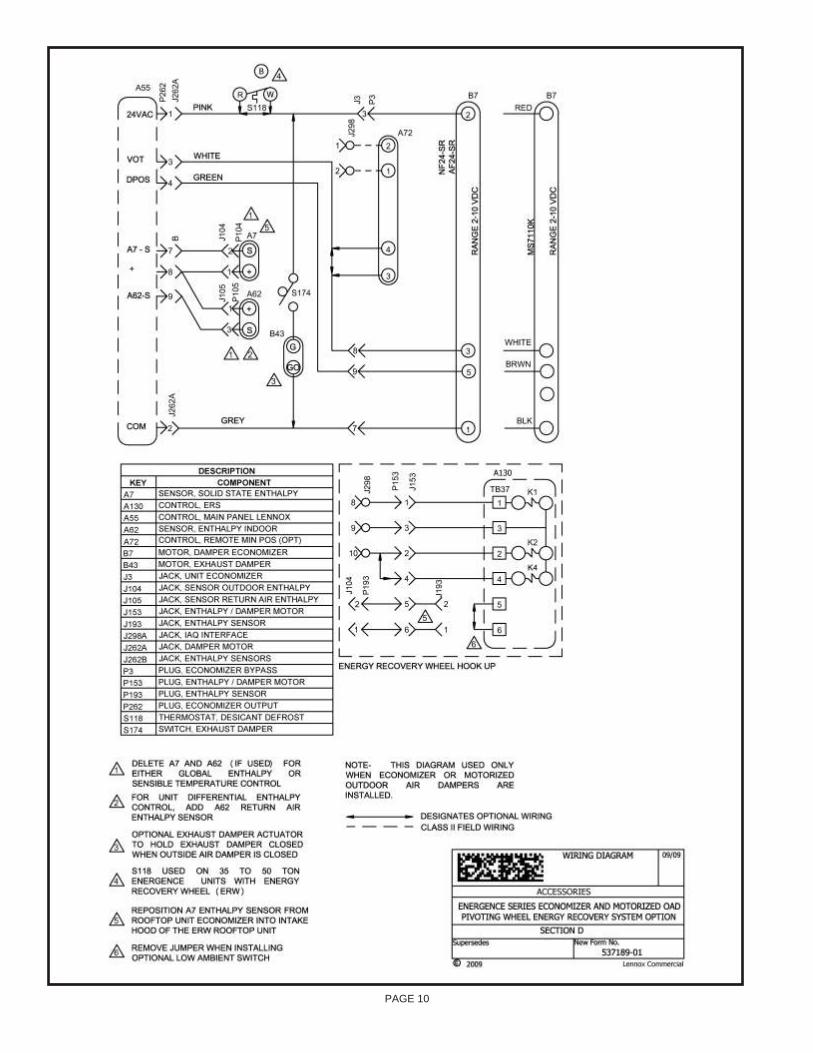
14. All electrical connections must conform to any localcodes and the current National Electric Codes (NEC)and Canadian Electric Code (CEC). Refer closely towiring diagram in unit and/or in these instructions forproper connections. Refer to the unit nameplate for the minimum circuit ampacity and maximum over currentprotection size. Electrical data is listed on unit ratingplate and motor nameplates.
15. Connect line voltage power to ERS unit from ERS fieldprovided or rooftop unit disconnect switch (disconnectmust be properly sized). Then connect line voltagefrom disconnect switch through ERS knockout onback panel to control box per the wiring diagram. SeeFigure 17 and 18.
16. Ground unit with a suitable ground connection eitherthrough unit supply wiring or earth ground.
Note: Unit voltage entries must be sealed weathertight after wiring is complete.
17. Replace access panels onto the ERS unit and secure.
Figure 17
Figure 18
ROOF TOP UNIT WIR ING(See Field Wir ing Dia gram)
1. Open access panel to rooftop unit controls.
2. The minimum damper blade position must be adjusted on the economizer logic module to the correct amountof outside air specified by the customer. Refer toLennox rooftop unit manual for setting.
Wheel Pivot Adjustment
The Electronic Configuration To Order (ECTO)parameter must be set at ECTO 7.22 = 10 to indicateERS is installed.
In the A55 Integrated Modular Controller II (IMC2)[Prodigy] of the RTU setting is required for theeconomizer to go to minimum outside air.
During default operation the ERS will start when theRTU unit blower is on and dampers are at minimumposition. The wheel will pivot out of the fresh air streamat power exhaust signal or free-cooling demand.
The A55 (IMC2) uses the following parameters tocontrol wheel position. See Figure 19.
For Smoke Mode reference the Smoke ModeOperation table on Page 6.
EN THALPY CON TROL WIRES
HIGH VOLT AGE ENTRANCE
PAGE 6
Motorized Intake Air DamperDamper mounts behind the outdoor air intake hood. Itopens when the ERS is energized and closes whende-energized. Powered by B30 damper motor.
Pressure SensorMeasurement device on the ERS to determine airflowacross the Enthalpy Wheel.
Low Ambient Control Kit (S26)Prevents frost formation on energy wheel heat transfersurfaces by terminating the intake blower operation whendischarge air temperature falls below a field selectabletemperature setting. Intake blower operation resumesoperation after temperature rises above the adjustabletemperature differential.
The frost threshold is the outdoor temperature at whichfrost will begin to form on the ERS wheel. For energyrecovery systems, the frost threshold is typically below10oF. Frost threshold is dependent on indoor temperatureand humidity. The table shows how the frost thresholdtemperatures vary depending on indoor conditions.
FROST THRESH OLD TEM PER A TURE
IN DOOR RH AT 70oF FROST THRESH OLD TEM PER A TURE
20% 0oF30% 5oF40% 10oF
Because ERS have a low frost threshold, frost controloptions are not necessary in many climates. Whereoutdoor temperatures may drop below the frost thresholdduring the ERS operational hours, exhaust only frostcontrol option is available.
OP TIONAL KITS (Fac tory In stalled)
At startup, IfECTO 7.22 = 10(ERS Installed)
Blower on &Lennox
economizer >=min. position
ERS onD01 = 1D02 = 0
Power Exhaust onOR
Free-Cooling
ERS onD01 = 1D02 = 1
ERS onD01 = 0D02 = 0
Yes
Yes
Yes
No
No
Notes:1. D01( turns on B28, B26, B27 thru ERS controller) and
D02 (turns on B29 thru ERS controller) are relay outputs from Lennox IMC2 control board.
2. B28 - ERS Wheel Motor, B26 - ERS Exhaust Air Blower, B27 - ERS Fresh Air Blower, B29 - ERS Wheel pivot/dampermotor
Figure 19
Nor mal Op er a tion
Smoke Mode Set ting(ECTO 5.01)
Blower D02 Damper D01
0, unit off (de fault) OFF OFF Closed OFF
1, pos. pressure ON OFF 100% Open ON
2, neg. pressure ON ON Closed ON
3, purge ON ON 100% Open ON
4, neg. pressure OFF ON Closed ON
5, neg. pres sure ON ON Closed ON
6, purge ON ON 100% Open ON
7, neg. pres sure OFF ON Closed ON
Smoke Mode Op er a tion
ECONO MIZER SET TINGS
Refer to economizer instructions for minimum air flowrequirement. The damper setting on the internaleconomizer assembly are field adjustable to any positionabove minimum air flow for fresh air requirements at thecustomers specified conditions.
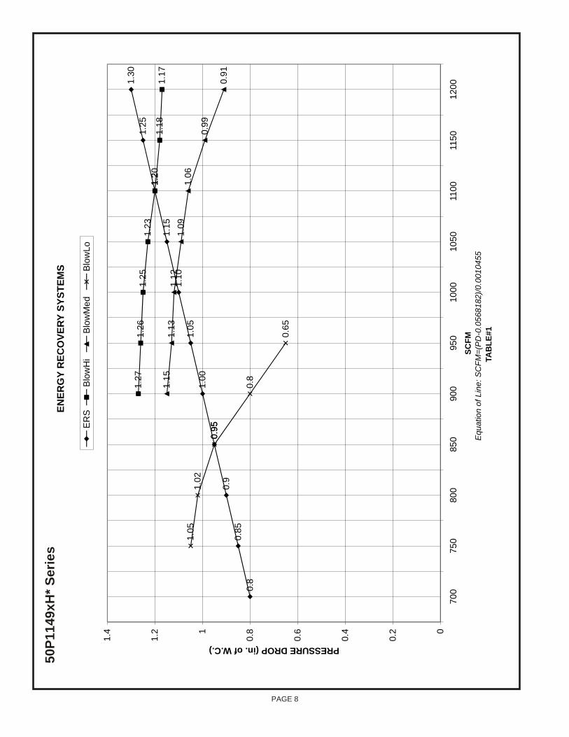
BLOWER SPEED AD JUST MENT
Blower speed selection is accomplished by changing thespeed tap wire (refer to wiring diagram) on both fresh airand exhaust air blowers. All blowers are factory set at"high" for maximum airflow. To determine air flow setting,external static pressure readings will need to be readacross the ERS. Reference Table 1 shown on page 8.For location to take pressure readings. See Figure 20.
Figure 20
DELTA PRES SURE FRESH AIR
DELTA PRES SURE EX HAUST AIR
3. Close access panels on the rooftop unit and secure.
4. Restore power to unit.
5. Once ERS is working properly, caulk any open joints,holes, or seams to make the units completely air andwater tight.
6. Leave this instruction manual with owner or in anenvelope to be kept near unit.
MAINTENANCE
Motor MaintenanceAll motors use prelubricated sealed bearings; no furtherlubrication is necessary.
Mechanical InspectionMake visual inspection of dampers, linkage assembliesand ERS rotating bearings during routine maintenance.Filters should be checked periodically and cleaned whennecessary. Filter is located in fresh air hoods. DO NOTreplace permanent filters with throwaway type filters.
En ergy Wheel Main te nanceFour pie-shaped energy recovery wheel seg ments areseated on stops be tween the stain less steel springre tain ers, se cured to the hub and rim of wheel. An nualin spec tion of the self clean ing wheel is rec om mended.With power dis con nected, re move ERS ac cess pan els(rear) and un plug (J150 & P150). Re fer to wir ing di a gram in this in struc tion man ual. Each seg ment is se cured in placeby a stain less steel spring re tainer lo cated on wheel rim.Re move one end of the stain less steel spring re tainer fromthe slot in the wheel rim and re move. Do the same on thenext re tainer. Re move seg ment and wash with wa terand/or mild de ter gent. Re place seg ment by re vers ing theabove pro ce dure. See Fig ure 21. Dis col or ation andstain ing of ERS seg ment does not af fect its per for mance.Only ex ces sive buildup of for eign ma te rial need bere moved. If the seg ment ap pears ex ces sively dirty, itshould be cleaned to en sure max i mum op er at ingef fi ciency. Thor oughly spray plas tic sur face withhouse hold cleaner such as Fan tas tic or equiv a lentmid dle de ter gent and gently rinse with warm wa ter us ing asoft brush to re move heavier ac cu mu la tion. Shake excesswater from segment and replace in reverse of removalinstructions.
PAGE 7
1. Disconnect ERS main power.
Note: If Low ambient kit S26 is used the jumperbetween TB37-5 and TB37-6 should be removed.Also if system check out is being conducted at lowambient temperatures, jumper low ambientswitch.
2. Open rooftop unit blower access panel and locateTB1. Jumper terminals 6 (24v) and 3 (G) to energizerooftop unit blower. Refer to manufacturersinstructions when an electronic thermostat or otherenergy management system is used.
3. Remove ERS control access panel and install jumperat low voltage terminal strip between TB37-1 andTB37-2.
4. Restore power to ERS unit. The recovery wheel willpivot out of the air stream, fresh air blower damperswill open, and after a delay, the exhaust blower willoperate.
5. Remove jumper from ERS control board TB37-1 andTB37-2. The recovery wheel will pivot into the airstream, the fresh air blower dampers will close, andafter a delay, the fresh air blower and exhaust airblower will operate.
6. Disconnect main power to unit before makingadjustment to economizer and/or ERS unit.
7. Remove all jumpers and replace ERS control accesscover.
8. Set thermostat to normal operating position.
9. Restore power to unit.
SYSTEM CHECK
OPERATION
Re cov ery Wheel ModeOn a thermostat call for blower operation in heating,cooling or continuous blower, the ERS media will rotatebetween fresh air and exhaust air streams. Both the freshair blower and exhaust air blower will be operating.
Econo mizer/Power Ex haust ModeOn the activation of the economizer mode (closure of "EH"contact on logic module), the ERS unit will shutdown forapproximately 60 seconds to allow the ERS media to pivotout of the air stream. After this delay timer has beensatisfied, the exhaust air blower will operate. The ERS unitwill act as a power exhaust unit.
This mode will continue until economizer has beendeactivated. The exhaust air blower will shut down and thedelay timer will be activated. During this time period theERS media will pivot back into the air stream. When timingis complete the unit will operate in the Recovery WheelMode.
Then if economizer continues to close the ERS willshutdown when the "N" terminal is deactivated, thusallowing rooftop unit to run in night set back mode.
HUB
SEGMENT
FIGURE 21
SPOKE
SEGMENT RETAINER CATCHWHEEL RIM
SEGMENT RETAINER
PAGE 8
EN
ER
GY
RE
CO
VE
RY
SY
ST
EM
S
0.8
0.8
5
0.9
0.9
5
1.0
0
1.0
5
1.1
0
1.1
5
1.2
0
1.2
5
1.3
01.2
71.2
61.2
51.2
31.2
1.1
81.1
71.1
51.1
31.1
21.0
91.0
6
0.9
9
0.9
1
1.0
51.0
2
0.9
5
0.8
0.6
5
0
0.2
0.4
0.6
0.81
1.2
1.4
70
075
080
085
090
095
010
00
10
50
110
011
50
12
00
SC
FM
Equ
atio
n o
f L
ine
: S
CF
M=
(PD
- 0.0
568
18
2)/
0.0
01
04
55
TA
BL
E #
1
PRESSUREDROP(in.ofW.C.)E
RS
Blo
w H
iB
low
Me
dB
low
Lo
seir
eS *
Hx
94
11
P0
5
PAGE 9
PAGE 10
PAGE 11
Len nox Model No. Req’d Curb Height CFM Range Volt age Phase
50P1149xH21 14" 700-1000 208- 230 1
50P1149xH23 14" 700-1000 208- 230 3
50P1149xH33 14" 700-1000 460 3
50P1149xH43 14" 700-1000 575 3
ERS Lay out
Clear ance 36"
Clear ance 18"
"4
2 e
cn
ara
elC
48.000502014414 Roof Curb
012104808Equipment Support
50P1149xH
49.578
2.093
Lennox Unit Outline
START UP INFORMATION SHEET
VOLTAGE - ERS UNIT
In com ing Volt age L1-L2 L1-L3 L2-L3
Run ning Volt age L1-L2 L 1-L3 L2-L3
Sec ond ary Volt age C (black) to G (green) Volts*
C (black) to W (white) Volts*
* With ther mo stat call ing.
AM PER AGE - ERS MO TORS
In take Mo tor: Nom i nal HP Rated Amps Run ning Amps
Ex haust Mo tor: Nom i nal HP Rated Amps Run ning Amps
Wheel Mo tor: Nom i nal HP Rated Amps Run ning Amps
AIR FLOW
In take De sign CFM Pres sure Drop Cal cu lated CFM
Ex haust De sign CFM Pres sure Drop Cal cu lated CFM
Amb. db Temp Re turn Air db Temp* Tem pered Air db Temp*
Amb. wb Temp Re turn Air wb Temp* Tem pered Air wb Temp*
* Mea sure af ter 15 min utes of run time
IN STAL LA TION CHECK LIST
Model # Se rial #
Owner Owner Phone #
Owner Ad dress
In stall ing Con trac tor Start Up Me chanic
q Inspect the unit for transit damage and report any damage on the carrier’s freight bill.
q Check model number to insure it matches the job requirements.
q Install field accessories and unit adapter panels as required. Follow accessory and unit installation manuals.
q Verify field wiring, including the wiring to any accessories.
q Check all multi-tap transformers, to insure they are set to the proper incoming voltage.
q Verify correct belt tension, as well as the belt/pulley alignment. Tighten if needed.
q Prior to energizing the unit, inspect all the electrical connections.
q Power the unit. Bump the motor contactor to check rotation. Three phase motors are synchronized at thefactory. If blower motor fans are running backwards, de-energize power to the unit, then swap two of the threeincoming electrical lines to obtain proper phasing. Re-check.
q Perform all start up procedures outlined in the installation manual shipped with the unit.
q Fill in the Start Up Information as outlined on the opposite side of this sheet.
q Provide owner with information packet. Explain the thermostat and unit operation.


![Honda Marine accessories 2015 - alinder.ch Marine accessories 2015 HONDA . GENUINE PARTS. ... Service kits & Water pump kits & Rebuild kits [J ] ... Oil pressure / Overheat / PGM-FI](https://static.documents.pub/doc/80x56/5ad1ae8b7f8b9afa798be027/honda-marine-accessories-2015-marine-accessories-2015-honda-genuine-parts-.jpg)


