IDS’2018 – 21st International Drying Symposium València, Spain, 11-14 September 2018 DOI: http://dx.doi.org/10.4995/ids2018.2018.7512 21 ST INTERNATIONAL DRYING SYMPOSIUM EDITORIAL UNIVERSITAT POLITÈCNICA DE VALÈNCIA Energy analysis and conservation opportunities in spray dryers Patel, S. K. a ; Bade, M. H. b* a Research Scholar, Sardar Vallabhbhai National Institute of Technology, Surat, Gujarat, India. b Faculty, Department of Mechanical Engineering, Sardar Vallabhbhai National Institute of Technology, Surat, Gujarat, India. *E-mail: [email protected], [email protected]Abstract Dryers are used for removal of moisture from an raw materials (such as effluent) to form a dried solids as per the requirements. For removal of the moisture, energy requirement is huge. Therefore, in this paper, methodology for heat recovery in one of the type of dryers as spray dryers is developed, which is simple and easy to apply. The proposed methodology is illustrated with the help of an example taken from literature. It is observed that the indirect heat recovery method could save energy maximum up to 82 % as compared to literature and 41 % higher than without heat recovery. Keywords: Spray dryer, pinch analysis, heat recovery, effluent drying, energy saving. 139
Transcript
IDS’2018 – 21st International Drying Symposium València, Spain, 11-14 September 2018
DOI: http://dx.doi.org/10.4995/ids2018.2018.7512
21ST INTERNATIONAL DRYING SYMPOSIUM
EDITORIAL UNIVERSITAT POLITÈCNICA DE VALÈNCIA
Energy analysis and conservation opportunities in spray dryers
Patel, S. K.a ; Bade, M. H.b* aResearch Scholar, Sardar Vallabhbhai National Institute of Technology, Surat, Gujarat, India. bFaculty, Department of Mechanical Engineering, Sardar Vallabhbhai National Institute of Technology, Surat, Gujarat, India. *E-mail: [email protected], [email protected]
Abstract Dryers are used for removal of moisture from an raw materials (such as effluent) to form a dried solids as per the requirements. For removal of the moisture, energy requirement is huge. Therefore, in this paper, methodology for heat recovery in one of the type of dryers as spray dryers is developed, which is simple and easy to apply. The proposed methodology is illustrated with the help of an example taken from literature. It is observed that the indirect heat recovery method could save energy maximum up to 82 % as compared to literature and 41 % higher than without heat recovery.
Energy analysis and conservation opportunities in spray dryers
21ST INTERNATIONAL DRYING SYMPOSIUM EDITORIAL UNIVERSITAT POLITÈCNICA DE VALÈNCIA
1. Introduction
Spray dryer has been used for the removal of liquids by evaporation from concentrated solid solutions giving product out in the form of powder with various grain sizes. In recent years, it also become part of waste management treatment employed for removal of water part from effluent getting dried solid waste. Industrial effluents (dissolved liquid wastes) are produced as a waste from industrial and commercial activities from diversed field such as food, textile, oil, chemicals, pesticides etc. [1]. Effluents production in India will rise per capita rate of around 1 to 1.33 % annually from 2021 to 2031 [2]. In spray dryers, fluid atomized through the atomizer in the form of fine droplets, which instantly comes into contact with a flow of hot air, results in vaporization of liquid part of it. Spray dryers consume substantial thermal energy around 10 - 20 % of total industrial energy usage in most of the developed countries [3]. It is observed that a significant heat energy is wasted in the form of gases, exhaust from industrial effluent dryers. Many researchers have studied recovery of waste heat by different methods such as partial recirculation of exhaust gases as direct heat recovery, heating inlet fresh air by exhaust gases as indirect heat recovery, etc. Kilkovsky et al. [4] studied indirect heat recovery from flue gases of waste and biomass incinerator plant. Ogulata [5] investigated the potential of heat recovery in textile drying by using heat exchangers such as recuperators, regenerators and heat pumps. The methodology proposed for the determination of Performance characterstics and efficiency of heat exchanger, heat pump and combined system (heat exchanger and heat pump) are desciribed in details [6]. Johnson et al. [7] discussed various techniques of thermal system analysis to optimize drying process for spray dryer of air and superheated steam types and illustrated with case study of milk powder plant. Golman and Julklang [8] reported exhaust gas heat recovery through partial recirculation of exhaust air in spray dryer of alumina slurry plant. In this plant, alumina slurry is atomized and dried in spray dryer, recovering value added product from it. Bade and Bandyopadhyay [9] proposed methodology for targeting the thermal oil required for process heating using pinch analysis and extended it for integration of other thermal systems. There is a paucity of information in literature for heat recovery and energy analysis of industrial effluents spray dryer. The purpose of the current work is to develop mathematical model of spray dryer based on mass and energy balance equations and to propose simple methodology for indirect heat recovery of spray dryers depends on pinch analysis.
Feed supplied to dryer contents moisture in range of 30-40 % reduced from as high as 99 % [1] present in effluent by concentration in mechanical vapour recompression (MVR) and/or thermal vapour recompression (TVR). To analyze the energy performance of the dryers and to have simplicity for individual mass balance of solids in waste feed and dried powder as well as water in waste feed and moisture in exhaust and fresh air, each stream is shown
with mass of individual constituent content in it as shown in Fig. 1. Further, complete spray dryer is considered as control volume boundary with inlet and outlet streams and energy interaction with surrounding systems. The mathematical model is formulated on the basis of overall mass and energy balance equations applied to control volumes of dryer.
Fig. 1 Illustrative diagram of spray dryer.
2. Model of spray dryer without heat recovery
One of the approach to improve energy efficiecy of spray dryers is by recovering waste heat in exhaust either by indirectly or directly and recirculation of this thermal energy in to dryer. This energy recovery will be best analysed by developing the model of spray dryers. Model developed here is simple based on mass and energy balance equations. Overall mass and energy balance equations for the spray dryer is denoted as:
Energy analysis and conservation opportunities in spray dryers
21ST INTERNATIONAL DRYING SYMPOSIUM EDITORIAL UNIVERSITAT POLITÈCNICA DE VALÈNCIA
The difference between the quantity of water in the waste feed and water in the dry product is termed as water evaporated from the dryer. Mass of dry air is constant at inlet and outlet shown in Eq. (6a), only mass of water vapour are changing in air stream. Relations of humidity and dry air at various locations in the dryer are given by Equations (6b, c) and (7).
eada,hada, m= m (6a) hada,hahawv, m*= m ω (6b) hada,ha wevap.eawv, m*m= m ω+ (6c)
The humidity ratio at exhaust is given as: ( ) hada,,.ea m hawvwevap mm +=ω (7)
However, the minimum mass flow rate of dry hot air at inlet to drying chamber can be determined by simplifying mass and energy balance equations as:
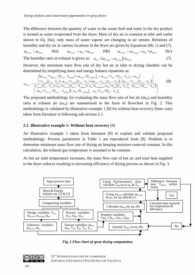
The proposed methodology for evaluating the mass flow rate of hot air (mha) and humidity ratio at exhaust air (ɷea) are summarized in the form of flowchart in Fig. 2. This methodology is validated by illustrative example 1 [8] for without heat recovery (base case) taken from literature in following sub-section 2.1. 2.1. Illustrative example 1: Without heat recovery [8]
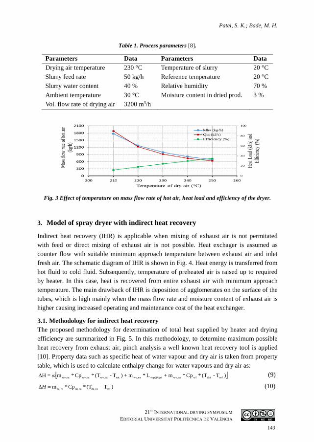
An illustrative example 1 taken from literature [8] to explain and validate proposed methodology. Process parameters in Table 1 are reproduced from [8]. Problem is to determine minimum mass flow rate of drying air keeping moisture removal constant. In this calculation, the exhaust gas temperature is assumed to be constant.
As hot air inlet temperature increases, the mass flow rate of hot air and total heat supplied to the dryer reduces resulting in increasing efficiency of drying process as shown in Fig. 3.
Fig. 2 Flow chart of spray drying computation.
Yes
Calculate mda,ha by eq. (8)
Using mda,ha calculate mwv,ha & ɷea by eq. (6b) & (7)
Using Psychrometric chart calculate Tdpt,ea at ɷea & Tea
Difference between new Tdpt,ea within limits
Calculate heat required for evaporation & efficiency
Parameters Data Parameters Data Drying air temperature 230 °C Temperature of slurry 20 °C Slurry feed rate 50 kg/h Reference temperature 20 °C Slurry water content 40 % Relative humidity 70 % Ambient temperature 30 °C Moisture content in dried prod. 3 % Vol. flow rate of drying air 3200 m3/h
Fig. 3 Effect of temperature on mass flow rate of hot air, heat load and efficiency of the dryer.
3. Model of spray dryer with indirect heat recovery
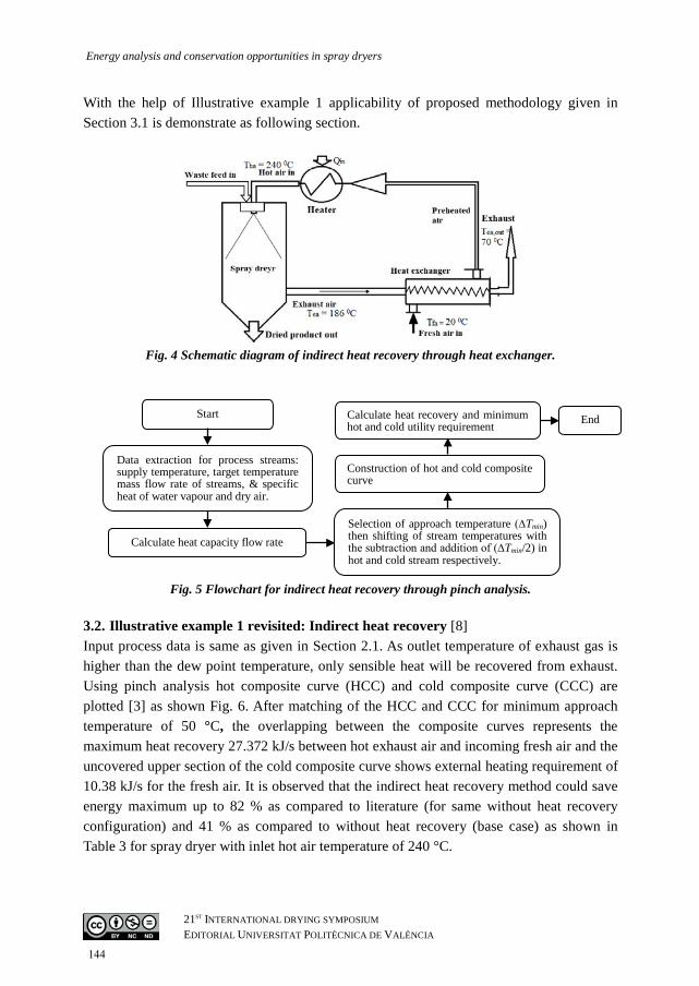
Indirect heat recovery (IHR) is applicable when mixing of exhaust air is not permitated with feed or direct mixing of exhaust air is not possible. Heat exchager is assumed as counter flow with suitable minimum approach temperature between exhaust air and inlet fresh air. The schematic diagram of IHR is shown in Fig. 4. Heat energy is transferred from hot fluid to cold fluid. Subsequently, temperature of preheated air is raised up to required by heater. In this case, heat is recovered from entire exhaust air with minimum approach temperature. The main drawback of IHR is deposition of agglomerates on the surface of the tubes, which is high mainly when the mass flow rate and moisture content of exhaust air is higher causing increased operating and maintenance cost of the heat exchanger.
3.1. Methodology for indirect heat recovery The proposed methodology for determination of total heat supplied by heater and drying efficiency are summarized in Fig. 5. In this methodology, to determine maximum possible heat recovery from exhaust air, pinch analysis a well known heat recovery tool is applied [10]. Property data such as specific heat of water vapour and dry air is taken from property table, which is used to calculate enthalpy change for water vapours and dry air as:
Energy analysis and conservation opportunities in spray dryers
21ST INTERNATIONAL DRYING SYMPOSIUM EDITORIAL UNIVERSITAT POLITÈCNICA DE VALÈNCIA
Start
Data extraction for process streams: supply temperature, target temperature mass flow rate of streams, & specific heat of water vapour and dry air.
Calculate heat capacity flow rate Selection of approach temperature (∆Tmin) then shifting of stream temperatures with the subtraction and addition of (∆Tmin/2) in hot and cold stream respectively.
Construction of hot and cold composite curve
Calculate heat recovery and minimum hot and cold utility requirement End
With the help of Illustrative example 1 applicability of proposed methodology given in Section 3.1 is demonstrate as following section.
Fig. 4 Schematic diagram of indirect heat recovery through heat exchanger.
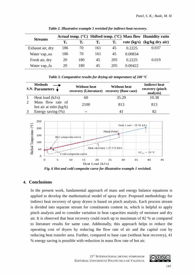
Fig. 5 Flowchart for indirect heat recovery through pinch analysis. 3.2. Illustrative example 1 revisited: Indirect heat recovery [8] Input process data is same as given in Section 2.1. As outlet temperature of exhaust gas is higher than the dew point temperature, only sensible heat will be recovered from exhaust. Using pinch analysis hot composite curve (HCC) and cold composite curve (CCC) are plotted [3] as shown Fig. 6. After matching of the HCC and CCC for minimum approach temperature of 50 °C, the overlapping between the composite curves represents the maximum heat recovery 27.372 kJ/s between hot exhaust air and incoming fresh air and the uncovered upper section of the cold composite curve shows external heating requirement of 10.38 kJ/s for the fresh air. It is observed that the indirect heat recovery method could save energy maximum up to 82 % as compared to literature (for same without heat recovery configuration) and 41 % as compared to without heat recovery (base case) as shown in Table 3 for spray dryer with inlet hot air temperature of 240 °C.
Table 3. Comparative results for drying air temperature of 240 °C
S.N. Methods Without heat
recovery (Literature) Without heat
recovery (Base case)
Indirect heat recovery (pinch
analysis) Parameters
1 Heat load (kJ/s) 60 35.29 10.38 2 Mass flow rate of
hot air at inlet (kg/h) 2100 813 813
3 Energy saving (%) -- 41 82
Fig. 6 Hot and cold composite curve for illustrative example 1 revisited.
4. Conclusions
In the present work, fundamental approach of mass and energy balance equations is applied to develop the mathematical model of spray dryer. Proposed methodology for indirect heat recovery of spray dryers is based on pinch analysis. Each process stream is divided into separate stream for constituents content in, which is helpful to apply pinch analysis and to consider variation in heat capacities mainly of moisture and dry air. It is observed that heat recovery could reach up to maximum of 82 % as compared to literature results for same case. Additonally, this approach helps to reduce the operating cost of dryers by reducing the flow rate of air and the capital cost by reducing heat transfer area. Further, compared to base case (without heat recovery), 41 % energy saving is possible with reduction in mass flow rate of hot air.
Energy analysis and conservation opportunities in spray dryers
21ST INTERNATIONAL DRYING SYMPOSIUM EDITORIAL UNIVERSITAT POLITÈCNICA DE VALÈNCIA
5. Nomenclature
m mass kg/h or kg/s T Temperature °C Q Heat load kJ/s H Enthalpy kJ/kg Cp Specific heat kJ/kgK °C L Latent heat of vaporization kJ/kg CP Heat capacity flow rate kJ/K °C
Greek letters
ɷ Humidity ratio kg water/kg dry air Subscripts
da dry air in input vap vaporization dp dry product min minimum w water dpt dew point temperature out outlet wf waste feed ea exhaust air ref reference wv water vapour evap evaporation s solid ha hot air sat saturation
6. References [1] Mujumdar, A.S., Handbook of industrial drying, Fourth ed., CRC Press : Taylor &
Francis, Boca Raton; London; New York 2015. [2] Dieter Mutz, Common Effluent Treatment Plants: Overview, Technologies and Case
Examples, New Delhi, India 2015. [3] Kemp, I.C., Fundamentals of Energy Analysis of Dryers. Modern Drying Technology
2014, 4–4, 1–45. [4] Kilkovsky, B.; Stehlik, P.; Jegla, Z.; Tovazhnyansky, L.L.; et al., Heat exchangers for
energy recovery in waste and biomass to energy technologies - Energy recovery from flue gas. Applied Thermal Engineering 2014, 64, 213–223.
[5] Ogulata, R.T., Utilization of waste-heat recovery in textile drying. Applied Energy 2004, 79, 41–49.
[6] Krokida, M.K.; Bisharat, G.I., Heat Recovery from Dryer Exhaust Air. Drying Technology 2004, 22, 1661–1674.
[7] Johnson, P.W.; Langrish, T.A.G.; Johnson, P.W.; Langrish, T.A.G., Inversion Temperature and Pinch Analysis , Ways to Thermally Optimize Drying Processes. Drying Technology 2011, 29, 488–507.
[8] Golman, B.; Julklang, W., Analysis of heat recovery from a spray dryer by recirculation of exhaust air. Energy Conversion and Management 2014, 88, 641–9.
[9] Bade, H.M.; Bandyopadhyay, S., Thermal integration of heat transfer fluid systems. Asia-Pacific Journal of Chemical Engineering 2013, 9, 1–15.
[10] Kemp, I.C., Reducing dryer energy use by process integration and pinch analysis. Drying Technology 2005, 23, 2089–2104.