Page 1
ENERGY ANALYSIS OF SOLAR CHIMNEY ASSISTED SOLARIUM WITH SEMI-
TRANSPARENT PHOTOVOLTAIC SYSTEM Afrooz Ravanfar, M.A.Sc. Ph.D. Student, Hua Ge, Assistant Professor,Ph.D., P.Eng., Zaiyi Liao, Professor,
M.SC., Ph.D., P.Eng.
Concordia University, Montreal, QC., Ryerson University, Toronto, ON. [email protected] , [email protected] , [email protected]
ABSTRACT
Previous study on the performance of a solar chimney
assisted solarium (SCAS) attached to a residential
building showed that the integration of a solar chimney
with a solarium enhances the natural ventilation of the
solarium and maintains interior conditions of the
building within the adaptive mean comfort temperature
limits. The objective of this study is to analyse the
energy performance of the above mentioned SCAS
integrated with Photovoltaic (SCASPV) system and
investigate effects of integrating PV cells in the solarium
under summer conditions.
A thermal model is developed and implemented in
SIMULINK to simulate the thermal response of solar
chimney assisted solarium combined with semi-
transparent photovoltaic system (STPV) using a heat
balance method. The greenhouse air temperature, its
ventilation rate and energy production of the STPV are
calculated. The numerical simulation results show that
the integration of SCAS system with STPV system
improves the performance of the system and produces
electricity that can be used for cooling the adjacent
building.
NOMENCLATURE
W Width (m)
L Length (m)
A Area (m2)
T Temperature ( K )
I incident solar radiation, kW/m2
S Solar radiation incident
hr Radiative heat transfer coefficient (W/m2 K)
hc Convective heat transfer coefficient
(W/m2 K)
h Convective heat transfer coefficient
(W/m2 K)
U U value (W/m2 K)
t Time (h)
"q
Heat transferred to the air stream
Coefficient of heat transfer
ṁ the air volume that cross the solarium (kg/s)
fc
Heat capacity of the air (KJ/kgK)
V Wind velocity (m/s)
fk
Thermal conductivity of air (1/K)
Nu Nusselt number
Ra Rayleigh number
Pr Prandtl number
i percentage of the solar radiation incident on
the STPV that is absorbed by layer i
Coefficient of expansion of air
emittance
f
Dynamic viscosity
g Gravitational constant (m/s)
Density of the air (kg/
3m )
ov
Air velocity when leaving the chimney
(m/s)
dC
Coefficient of discharge of air channel
Ɵ Tilt angle (Radian)
σ Stefan Boltzmann constant, W/(m2 K4)
Page 2
STPVP
Power output of PV
0
PV module efficiency at standard
conditions
c
Effective efficiency of PV
0
PV module temperature coefficient
coefficient of expansion of air
STPVA
Area of PV (m2)
Subscripts
S Solarium
Sc Solar chimney
a Ambient, air
f Fluid
g Glass
i Inlet
o Outlet
r Room
w Wall
b Floor
int Interior
in Inside
X, Y Surface number
E Soil
INTRODUCTION
In recent years, energy efficiency demands and
environmental concerns have influenced building
designers to reconsider natural ventilation in summer,
solar heating in winter and the use of daylighting in order
to reduce energy consumption in residential buildings.
On one hand, the addition of a solarium attached to a
house is a promising design alternative that can be
implemented in both retrofit and new buildings to
provide additional high quality space with abundant
solar radiation levels (Bastien and Athienitis, 2015).
According to Mihalakakou (2000), such a space may
improve the appearance of the building and reduce the
temperature swing and heating requirements of a house.
However, Bryn and Schiefloe (1996) found that an
improper design may raise the energy consumption of
the building or lead to frequent overheating and high
temperatures that are not desirable either for people or
plant growth. Hence, to maintain the desirable condition,
excess heat must be evacuated from the sunspace.
Ravanfar et al. (2014) introduced natural ventilation as
a common cooling technique in a highly glazed space
such as a solarium and emphasized on the role of natural
ventilation, not only for cooling the sunspace but also
the adjacent building. This research established a
methodology for evaluating the performance of a solar
chimney assisted ventilation system in a solarium
(SCAS) attached to a residential building at the initial
design stage. The proposed model showed that this
system
not only enhances the ventilation process inside the
solarium but also provides an energy saving potential to
its adjacent space. It was also found that the cross
sectional air movement produced by a SCAS in an
adjacent building can maintain the interior conditions
within the adaptive comfort standard (ACS) limits in
about 85% of the time in July, which results in a
potential cooling energy saving that would otherwise be
used by an air-conditioner. Results of this study was
validated by comparison between the numerical
predictions obtained from the simulation code of this
study and the theoretical and experimental results of
Afriyie et al. (2011).
On the other hand, the integration of semi-transparent
photovoltaics (STPV) in glazing systems has been
proved to have a large potential for producing electricity
while providing satisfactory daylight inside the building.
(Bahaj et al., 2008, James et al., 2009, Qiu et al., 2009).
Chow et al. (2007) conducted research on the energy
performance of clear, low-e and PV double glazed
windows. They found that the SHGC of the PV window
is the least compared to the other two fenestration
Page 3
systems; therefore, the heat gain in this system was
proved to be 200% less than the clear glass and 53% less
than low-e glass system. They also proved that naturally-
ventilated PV system can reduce the building energy by
reducing the air conditioning load by 28%.
Study by Li et al. (2012) showed that the STPV system
has the potential not only to decrease the peak cooling
load by 450W but also to reduce the overall building
energy consumption by 1203 MW. Peng et al. (2015)
conducted an experimental study on the energy and
thermal performance of PV double façade (PV-DSF)
system. They performed the research under various
ventilation conditions. Their results indicated that this
façade system reduces the heat gain under the ventilated
condition. The ventilated condition also improves the
power output of PV modules by 3%. However, this
number is notably higher on hot summer days, since the
operating temperature difference is larger.
The integration of STPV in the SCAS can not only
potentially reduce solar heat gain in the solarium, thus
reducing overheating risk, but also produce electricity
which can be used for cooling the adjacent building. As
a further study of the SCAS previously developed by
Ravanfar et al. (2014), this paper investigates the energy
performance of the SCAS integrated with STPV and its
effect on the natural ventilation airflow rates. In the
newly proposed SCASPV system, the glass cover in the
solarium is replaced by STPV system and its
performance is evaluated under transient summer
conditions.
METHODOLOGY
This study aims to analyze the energy performance
in the Solar Chimney Assisted Solarium (SCAS)
integrated semi-transparent photovoltaic system so as to
obtain the highest ventilation rate in the solarium and
adjacent residential building for the hottest period of the
year in the city of Toronto and to produce electricity that
may be used for cooling the adjacent building if needed.
To achieve this objective, a research methodology has
been envisaged that involves the following stages:
A detailed thermal analysis using the heat balance
method is performed to calculate the passive
thermal response of the SCAS with semi-
transparent photovoltaic system.
Thermal simulation is performed for critical
summer days using SIMULINK. The program
calculates the greenhouse air temperature and its
ventilation rate, using the actual weather data from
the city of Toronto.
PHYSICAL MODEL
In this study, a simple two-story residential building has
been simulated with the application of STPV in the
SCAS attached to the building. The simulated SCAS is
assumed to be located on the south side of a building in
the region of Toronto, Canada with the STPV wall and
roof facing south (zero azimuth). The total area of the
south facing wall in this SCAS is 11m2. Schematic side
section of the SCAS is presented in Fig. 1.
Fig. 1. Schematic side section of the SCAS
The roof tilt angle in this application is chosen to be 35o
and the total roof area in this system is 27m2. As it is
shown in Fig. 1, adjacent room air enters the solarium
through a bottom inlet. This air then absorbs energy in
L
Lsc
STPV
Ws
Concrete
Floor
Ao
Concrete
Back Wall
Living
space
Inlet
Ai
Wsc
Solar Chimney
Glass Cover
Ls
Page 4
the SCAS to be warmed up and finally exits into the
ambient air, inducing air flow from living space to the
outdoor. Uniform cross sections are assumed throughout
the solar chimney in this application. It is assumed in this
study that the air inside the solarium is replaced entirely
by the adjacent room air and the friction is ignored inside
the SCAS between air and interior surfaces.
With the above assumption, �̇� is the air mass flow rate
(kg/s), which can be expresses as follows: (Bansal et al.
(1993) and Andersen (1995)
�̇� = 𝜌𝐴𝑜𝑣𝑜 (1)
�̇� = 𝐶𝑑
𝜌𝑓𝑜𝐴𝑜
√1 + (𝐴𝑜
𝐴𝑖)
2
√2𝑔𝐿(𝑇𝑓𝑠𝑐 − 𝑇𝑟)
𝑇𝑟
(2)
Where 𝐶𝑑, coefficient of discharge of air channel, which
has the value of 0.57.according to Flourentzou et al.
(1997).
THERMAL BALANCE MODEL
A thermal balance model integrating STPV module with
the SCAS is developed in this study. Most of the solar
radiation enters the interior environment directly
through the glass. Referring to both surfaces of the
modules, absorbed heat is exchanged with the ambient
environment by means of convection and radiation. The
solar cell part of the module consists of three layers
which are front glass, solar cell and back glass. The front
glass directly contacts with the outdoor environment,
while the back glass directly contacts with the indoor.
Energy balance method has been employed to determine
different temperatures in the SCAS. Fig. 2 illustrates the
physical heat exchange process in this model.
Fig. 2. Heat transfer process in the dynamic model of SCAC
Since the heat transfer in highly glazed spaces such as a
SCAS is a very complicated process, the following
assumptions have been made to simplify the calculation.
The air inside the solarium and the solar chimney
are assumed to be well mixed and have only one
value each.
The glass surfaces in the solarium are assumed to
have four surfaces with four different surface
temperature values.
The glass surface in the solar chimney, concrete
walls and floor in the solarium and chimney are
also assumed to be at a constant temperature.
Thermal inertia of the glass and the air inside the
SCAS are negligible.
Heat flow in the model is one dimensional.
The glass walls and roof are opaque to the diffused
radiation from thermal masses throughout the
model.
The assumption of one air temperature inside solarium
and solar chimney is based on literature by (Hussain and
Oosthuizen, 2011), who found that the measured vertical
air temperature difference between top and bottom in a
three story, naturally ventilated highly glazed atrium
space is about 1oC.
Page 5
Since the SCAS system studied is physically close to
above mentioned atrium building and it is shorter in
height (4.5m compare to 10.9m height of the atrium) and
smaller in size, the air temperature difference inside the
solarium and solar chimney can be assumed to be
negligible since this study aims at evaluating the
performance of the SCAS at the initial design stage.
SCAS CONCRETE WALLS AND FLOOR
THERMAL MODEL
Thermal mass of the concrete back walls and floor plays
a critical role in the performance of the SCAS. Energy
balance on the concrete wall of the solarium can be
expressed as follows:
dt
dTCTTUTTh
TThTThS
pnr
nww
nf
nww
ng
nwrwg
nb
nwrwbw
)()(
)()( 4
(3)
The energy balance on the concrete wall of the solar
chimney is as follows:
dt
dTCTThTTh
TThTThTThS
pna
nwwind
nsky
nwrws
nf
nww
ng
nwrwg
nb
nwrwbw
)()(
)()()(
(4)
Where skyT sky temperature which is given by
(Swinbank, 1963):
5.1.0552.0 TskyT (5)
The energy balance on the solarium concrete floor as
follows:
dt
dT
pCT ET n
bbUT n
fT nbb
h
T nwT n
brbwhT n
gT nbrbg
hb
S
)()(
)()(
(6)
The temperatures of each heat absorbing walls and the
floor are characterized by 14 interior temperatures of
Twi, Tbi and 2 surface Temperatures of Tw0, TwI, Tb0 and
TbI.
SCAS FLUIDS HEATING MODELS
The energy balances of the fluid, air inside the solarium
and the solar chimney, considering the air being well
mixed with one temperature (Tf), have the following
time-dependent expressions:
Solarium:
)0()0()()4( TnfT
nbbhT
nfT
nwwhT
nrT
nfMT
ngT
nfgh
(7)
Solar chimney:
)()()0( TnfsT
nfMT
ngT
nfghT
nfT
nwwh
(8)
According to the bulk fluid temperature relation
(Hirunlabh et al., 1999; Ong and Chow, 2003) the fluid
average temperature related to the inlet and outlet can be
expressed as follows (ref.):
fiTfoTfT )1( (9)
, coefficient of heat transfer to the air stream which
flows out, Afriyie et al. (2011) found the value of 0.756
for the sc and explored that for various configurations
of the solarium 𝛾𝑠 is dependent to the tilt angle (ƟRad)
and has the following form:
0844.0084.12
3856.0 s (10)
The heat transferred to the air stream inside the solarium
can be written as follows:
)(
)(
" rTfTM
WL
fiTfTfc
dt
m
q
(11)
Where M heat that leaves the solarium, can be
explained as:
Page 6
WL
fcm
M
(12)
GLASS HEATING MODEL
As it was explained earlier, a unique temperature is
assigned for the glass cover and the thermal inertia of the
glass is ignored. With these assumptions, the energy
balance on the glass wall of the solar chimney and east
and west faced walls in the solarium can be expressed as
follows:
)()(
)0()0()(
TnskyT
ngrgshT
naT
ngwindh
TngT
nbrbghT
ngT
nwrwghT
ngT
nfghgS
(13)
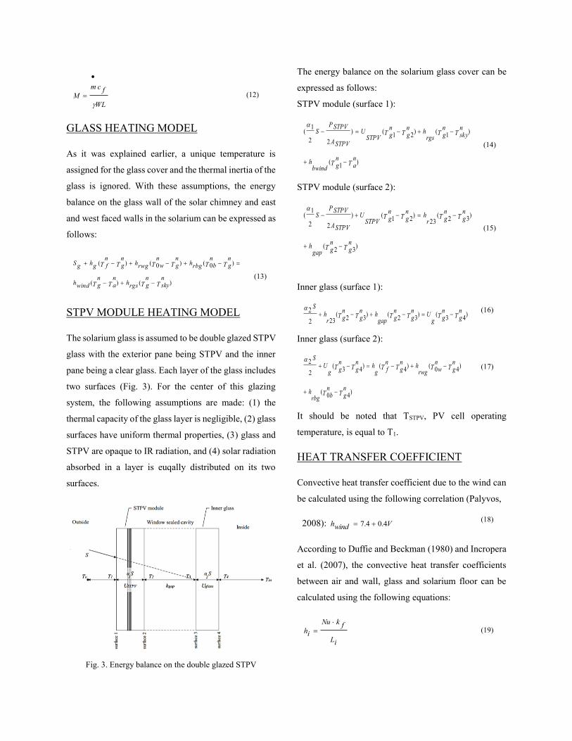
STPV MODULE HEATING MODEL
The solarium glass is assumed to be double glazed STPV
glass with the exterior pane being STPV and the inner
pane being a clear glass. Each layer of the glass includes
two surfaces (Fig. 3). For the center of this glazing
system, the following assumptions are made: (1) the
thermal capacity of the glass layer is negligible, (2) glass
surfaces have uniform thermal properties, (3) glass and
STPV are opaque to IR radiation, and (4) solar radiation
absorbed in a layer is euqally distributed on its two
surfaces.
Fig. 3. Energy balance on the double glazed STPV
The energy balance on the solarium glass cover can be
expressed as follows:
STPV module (surface 1):
)1
(
)1
()21
()
22
1(
TnaT
ngbwind
h
TnskyT
ngrgs
hTngT
ngSTPV
U
ASTPV
P STPVS
(14)
STPV module (surface 2):
)32
(
)32
(23
)21
()
22
1(
TngT
nggap
h
TngT
ngr
hTngT
ngSTPV
U
ASTPV
P STPVS
(15)
Inner glass (surface 1):
)43
()32
()32
(232
2T
ngT
ngg
UTngT
nggap
hTngT
ngr
hS
(16)
Inner glass (surface 2):
)40
(
)40
()4
()43
(2
2
TngT
nbrbg
h
TngT
nwrwg
hTngT
nfg
hTngT
ngg
US
(17)
It should be noted that TSTPV, PV cell operating
temperature, is equal to T1.
HEAT TRANSFER COEFFICIENT
Convective heat transfer coefficient due to the wind can
be calculated using the following correlation (Palyvos,
2008): Vwindh 4.04.7 (18)
According to Duffie and Beckman (1980) and Incropera
et al. (2007), the convective heat transfer coefficients
between air and wall, glass and solarium floor can be
calculated using the following equations:
iL
fkNu
ih
(19)
Page 7
Nu Nusselt number, has the following mathematical
forms (Incropera and DeWitt, 1996):
Laminar flow, Ra<109
9/416/9Pr)/492.0(1
4/167.0
68.0
Ra
Nu
(20)
In case of turbulent flow when Ra>109
2
27/816/9Pr)/492.0(1
6/1387.0
825.0
Ra
Nu
(21)
Physical properties of the air that were introduced by
Ong and Chow (2003) have been used in the study. The
convective heat transfer coefficient between collecting
wall and the living space, hc,int, can be calculated as:
3/131.1,int rTwTch
(22)
The following correlation is used to calculate the
radiative heat transfer coefficients between back wall
and the glazing and between solarium glass surfaces 2
and 3 (Marti- Herrero and Heras-Celemin (2006) :
1
yε
1
xε
1
)2yT
2x)(TyTxσ(T
rxyh
(23)
σ is the Stefan–Boltzmann constant, 8
1067.5
. The
radiative heat transfer coefficients between solarium
concrete floor with the glass cover and concrete, based
on Afriyie et al. (2011) are expressed as follows:
bAiAi
i
bAb
b
iTbTiTbT
bArbih
111
)22
)((
(24)
The radiative heat transfer coefficient between the sky
and the SASC glass surfaces and solar chimney back
wall can be calculated using the following (Marti-
Herrero and Heras-Celemin, 2006):
)22
)(( skyTiTskyTiTrish
(25)
STPV ELECTRICAL MODEL
As mentioned earlier, the glass in the solarium of the
SCAS is replaced by STPV. In this study the glass is
assumed to be replaced by Poly-Si PV window consists
of: (1) 10.9 mm STPV module, (2) 12.7 mm sealed
cavity (3) 5.9 mm coated glass. The theoretical electrical
efficiency of the PV modules as a function of their
temperature can be described as follows:
)]0(01[0 TcTc
(26)
The efficiency of the Poly-Si PV module in this
application is 12.53% and the installed capacity of above
mentioned area of such system is around 5KWp (Gaur
and Tiwari, 2013).
PSTPV, the power output or
of the STPV, can be calculated by (
:
cSTPVAtISTPVP .).(
(27)
The daily electrical energy in KWh is obtained by
)1 1000/( Ni hourly
Edaily
E
(28)
Where N1 is the number of sun shine hours per day (Gaur
and Tiwari, 2013).
According to Gaur and Tiwari (2013), poly-Si PV panels
had the minimum annual electric energy generation and
heat tolerance compared to the other semitransparent PV
cells. Therefore, a conservative product is chosen in this
study to investigate the feasibility of integrating STPV
with SCAS.
Fig. 9. Shows the calculated electricity generation by
photovoltaic cells used in this application during the
month of July.
Page 8
RESULTS AND DISCUSSION
Thermal simulation was performed during the critical
summer days (month of July) using the
MATLAB/SIMULINK model validated in the previous
study by Ravanfar et al. (2014).
Fig. 4. Toronto ambient temperature for the month of July
The program calculates the greenhouse air temperature
and its ventilation rate when the glass in the roof and
south facing wall of the solarium is replaced by STPV
completely. Simulations are carried out using actual
weather data for Toronto. Fig. 4 shows the ambient
temperature and Fig. 4 shows solar radiation for the
month of July. (Figs.4-5).
Fig. 5. Toronto solar radiation on south faced horizontal
surface for the month of July
As shown in Fig. 7 the fluid (inside air) temperature of
the chimney is notably higher than that of the solarium
even in the new system. With the application of STPV
in the SCAS the solarium and solar chimney air
temperatures are notably lowered, which improves the
living condition inside the solarium (Figs. 6-7). The
solarium fluid temperature stays around ambient
temperature and in some days even lower than the
outside temperature except for days with high solar
radiation. However, due to the fact that air temperature
is higher inside the solar chimney the system is still able
to maintain a reasonably high flow rate. It should be
mentioned here that even though the maximum flow rate
for each day is lower compared to the old SCAS, the new
system produces relatively higher flow rate during the
nights (Fig. 8). The flow rate is higher than 0.065 kg/s
during the whole simulation time. The air flow rate is the
lowest value around sunrise. The minimum flow rate is
as high as 0.08 - 0.1 kg/s and is related to the sunrise
hours (5 am). The air flow rate reaches its maximum
around 1 pm following the same pattern as the old
SCAS. The mean minimum airflow rate is 0.1kg/s,
which is equivalent to 1.08ACH for a 300m2 adjacent
house.
Fig. 6. Air Temperature inside the old SCAS
0
5
10
15
20
25
30
35
0 5 10 15 20 25 30
Tem
per
ature
(oC
)
Time (day)
0
100
200
300
400
500
0 5 10 15 20 25 30
So
lar
radia
tio
n (
W/m
2)
Time (day)
0
10
20
30
40
50
60
70
80
90
0 5 10 15 20 25 30
Tem
per
atu
re (
oC
)
Time (day) Ambient temperature
Solar chimney air temperature
Solarium air temperature
0
10
20
30
40
50
60
70
80
90
0 5 10 15 20 25 30
Tem
per
ature
(o
C)
Time (day) Ambient temperature
Solar chimney air temperature
Solarium air temperature
Page 9
Fig 7. Air temperature inside the SCAS with STPV
Fig. 8. The mass flow rate that crosses the SCAS
Fig 9. Shows the amount of electricity generated by
STPV during the month of July. The total energy
generated for the month of July is 709 KWh.
Fig. 9. Generated electricity by STPV during the month of July
CONCLUSION
This study evaluated the performance of a previously
investigated SCAS with the glass in the solarium
replaced by STPV under the critical summer days
(month of July) in Toronto. The numerical results show
that compared to the previous version of the SCAS, the
ventilation performance of the new system stays fairly
close to the old system. Such a system can effectively
lower solarium heat gain and therefore, thermal comfort
can be enhanced inside the SCAS and adjacent building.
The new system can also function to generate electricity.
The findings of this study are encouraging and the
technology deserves more attention and can be a reliable
reference for future experimental investigations.
REFERENCES
Afriyie, J.K., Rajakaruna, H., Nazha, M.A.A., Forson,
F.K., 2011. Simulation and optimisation of the
ventilation in a chimney-dependent solar crop dryer,
Solar Energy 85: 1560–1573.
Andersen, K.T., 1995. Theory for natural ventilation by
thermal buoyancy in one zone with uniform
temperature, Building and Environment 38: 1281–1289.
Bansal, N.K., Mathur, R., Bhandari, M.S., 1993. Solar
chimney for enhanced stack ventilation, Building and
environment 28: 373–377.
Bastien, D., Athienitis, A.K., 2015. Development of a
new control strategy for improving the operation of
multiple shades in a solarium, Solar Energy, 122: 277–
292.
Bahaj, A.S., James, P., Jentsch, M.F., 2008. Potential of
emerging glazing technologies for highly glazed
buildings in hot arid climates. Energy Build. 40: 720–
731.
Bryn, I., Schiefloe, P. 1996. Atrium models for the
analysis of thermal comfort and energy use: a report of
task 12. SINTEF Energy, Trondheim.
Chow, T.T., Fong, K.F., He, W., Lin, Z., Chan, A.L.S.,
2007. Performance evaluation of a PV ventilated
window applying to office building of Hong Kong.
Energy Build 39: 643–650.
Duffie, J.A., Beckman, W.A., 1980. Solar engineering
of thermal processes, Wiley, New York.
Flourentzou, F., Van der Maas, J., Roulet, C., A., 1997.
Natural ventilation for passive cooling: measurement of
discharge coefficients, Energy and Building 27: 283-
292.
0.06
0.07
0.08
0.09
0.1
0.11
0 5 10 15 20 25 30
Mas
s fl
ow
rat
e (k
g/s
)
Time (day)
0
500
1000
1500
2000
2500
3000
3500
4000
0 5 10 15 20 25 30
Gen
erat
ed e
lect
rici
ty (
Wat
t)
Time (day)
Page 10
Gaur, A., Tiwari, G. N., 2013. Performance of
Photovoltaic Modules of Different Solar Cells, Solar
Energy 2013: 734581
Hirunlabh, J., Kongduang, W., Namprakai, P., Khedari,
J., 1999. Study of natural ventilation of houses by a
metallic solar wall under tropical climate, Renewable
Energy 18: 109-119.
Hussain, S., Oosthuizen, P. H., 2011. Validation of
numerical modelling of conditions in an atrium space
with a hybrid ventilation system, Building and
Environment, Vol. 52: 152–161
Incropera, F.P., De Witt, D.P., Bergman, T.L., Lavine,
A.S., 2007. Introduction to Heat Transfer, fifth ed. John
Wiley & Sons Inc., Hoboken, New Jersey.
James, P., Jentsch, M., Bahaj, A., 2009. Quantifying the
added value of BiPV as a shading solution in atria. Sol.
Energy 83: 220–231.
Kemery, B. P., Beausoleil-Morrison, I., Rowlands, I. H.,
2012. Optimal PV orientation and geographic
dispersion: a study of 10 Canadian cities and 16 Ontario
locations, eSim 2012: 136-149
Li, G., Zhu, R., Yang, Y., 2012. Polymer solar cells. Nat.
Photon 6: 153– 161.
Marti-Herrero, J., Heras-Celemin, M.R., 2006. Dynamic
physical model for a solar chimney, Solar Energy 81:
614-622.
Mihalakakou, G., Santamouris, M., Asimakopoulos,
D.N., 2000. The total solar radiation time series
simulation on Athens, using neural networks.
Theoretical and Applied Climatology, 66: 185-197.
Palyvos, J.A., 2008. A survey of wind convection
coefficient correlations for building envelope energy
systems’ modeling, Applied Thermal Engineering 28:
801-808.
Peng, J., Lu, L., Yang, H., Ma, T., 2015. Comparative
study of the thermal and power performances of a semi-
transparent photovoltaic façade under different
ventilation modes, Applied Energy, 138: 572–583.
Qiu, Z., Chow, T.T., Li, P., Li, C., Ren, J., Wang, W.,
2009. Performance Evaluation of the Photovoltaic
Double Skin Facade, 11th International IBPSA: 2251–
2257.
Ravanfar, A., Liao, Z., Ge, H., 2014, Simulation study
of solar chimney assisted solarium, NSB 2014: 838-845
Skoplaki, E., Palyvos, J. A., 2009. On the temperature
dependence of photovoltaic module electrical
performance: a review of efficiency/power correlations,
Solar Energy 83, no. 5, 614–624.
Stauffer, N. W., 2013. Transparent solar cells:
Generating power from everyday surfaces, Energy
Futures, spring 2013
Swinbank, W.C., 1963. Long wave radiation from clear
skies, Q.J.R. Meterol, Soc. 89: 339.
Ong, K.S., Chow, C.C., 2003. Performance of a solar
chimney, Solar Energy 74: 1-17.


![EXPERIMENTAL INVESTIGATIONS FOR IMPROVING PV MODULE ... · Vol. 10, Issue 2, Apr 2020, ... [6] used the solar chimney system to cool Semi-Transparent PhotoVoltaic (STPV) system. The](https://static.documents.pub/doc/80x56/5f7dac14f633245752180bf6/experimental-investigations-for-improving-pv-module-vol-10-issue-2-apr-2020.jpg)


