j ourna l ho me pa g e: www.elsev ier .com/ locate /enbui ld
eformation and thermal resistance study of aerogel blanketnsulation material under uniaxial compression
tiyeh Hoseini, Ali Malekian, Majid Bahrami ∗
aboratory for Alternative Energy Conversion, School of Mechatronic Systems Engineering, Simon Fraser University, 250-13450 102 Avenue, Surrey, Britisholumbia, V3T 0A3, Canada
r t i c l e i n f o
rticle history:eceived 13 June 2016eceived in revised form 15 August 2016ccepted 17 August 2016vailable online 18 August 2016
Aerogel based composite insulation materials have very low thermal conductivity (∼0.016 to ∼0.040W m−1 K−1). Aerogel blankets are flexible; however, compressive loads may affect their thermal resis-tance due to their porous nature. In this paper, the thermal resistance and mechanical deformation ofaerogel blankets were studied under compressive mechanical loading. The R-values of two types of com-mercially available aerogel blankets (Cryogel®Z and ThermalWrapTM) were measured using a heat flowmeter (HFM) under compressive loads up to 8 kPa. Additionally, a mechanistic analytical model wasdeveloped to predict the deformation of aerogel blankets using their microstructural properties, includ-ing average fiber diameter, particle diameter and porosity. The bending of fibers was considered as themain deformation mechanism at the unit cell level, and the overall blanket deformation was calculatedfrom the summation of the deformations of all the unit cells. The stress-strain relationship was verifiedusing the results of the experimental studies conducted with a HFM and a thermomechanical analyzer
TM
ompressionxperiment
(TMA). The maximum decrease in thickness was 20% for 8 mm ThermalWrap and the maximum changein R-value was a 10% increase with compression observed for a 10 mm Cryogel®Z. The results indicatedthat aerogel blankets remain remarkably effective thermal insulation materials under compression. Evenafter 20 compression-decompression loading cycles, the reduction of thermal conductivity was ≤5%, and
ion w
the permanent deformat
. Introduction
A staggering 64% of household energy use and 53% of commer-ial energy use in Canada were for heating and cooling purposes,ccording to data from year 2009 [1]. Using more efficient ther-al insulation system in buildings is a feasible approach to reduce
nergy demand as a result of reduced energy losses [2].The thermal performance of insulation materials is typically
udged by their R-value (thermal resistance value) determined bytandardized tests, such as ASTM C177 and C518; however, then-service R-value may differ for several reasons. For instance, R-alue decreases when porous material is compressed. The thermalesistance of insulations may also vary with temperature and pres-nce of moisture. These R-value variations are material specific andot linear. Among available insulating material categories, aerogelsre high performance insulations for both stationary and mobile
pplications.
Aerogels are highly porous materials with large surface areand pore volume. They have a low density and high porosity
(>90%), which makes them super thermal insulators [3] or greatadditives to enhance the insulation performance of the compositessuch as aerogel based plasters[4]. The highly porous structureof aerogels is formed by sol gel chemistry [5]. Although theyhave outstanding thermal insulating properties, the cost andweak mechanical strength of aerogels have limited their use. Onemethod of reinforcing aerogels is combining aerogel with a fibrousmatrix that supports the aerogel particles to create a compositecalled an aerogel blanket [6]. Aerogel blankets are flexible, highlyporous thermal insulators, which have remarkably high thermalresistance [5]. In this paper, aerogel blanket super insulation isstudied under compressive mechanical loading to investigate theeffect of uniaxial compression on its thermal performance andstructural deformation.
Yarbrough et al. [7] studied the reduction of thermal resistanceof loose-fill insulations due to mechanical compression and mea-sured the thickness reduction as a function of applied load forsamples of fiberglass batt, 1oose-fill fiberglass, loose-fill rock wool,and loose-fill cellulosic insulation. Their results showed that the
low density materials were affected the most showing up to 40%thickness decrease under 0.14 kPa load. Also, they showed thatreduction in thermal resistance under compression was greatest
A Area (m2)D Diameter (m)ε Porositye Strainı Deformation (m)EI Flexural rigidity (N m2)� Stress (kPa)F Force (N)Force (N)k Thermal conductivity (W m−1 K−1)a Aerogel particle layerl Length (m)App Apparentt Thickness (m)b BlanketN NumberCond Conductionq̇ Heat flux (W m−2)eff EffectiveRtotal Total thermal resistance (m2 K W−1)F Fiberr Radius (m)G GasT Temperature (K)Gs Gas solid regionV Volume (m3)Sm Solid mediumlp Large particletot Totalu Unit cell total
faucavtCrdpbpfiTbrt[isATotfcoamp
tot
or the fiberglass insulations (∼20% under 0.14 kPa load). Adamsnd Hust [8] investigated the reduction of thermal conductivitynder compression for five common porous insulation products;ellulose, rock/slag wool, bonded and unbonded glass fiber, and
glass fiber blanket. Graves and Yarbrough [9] measured the R-alues of six commercially available fiberglass batts at their fullhickness and compressed to 50% of full thickness, following ASTM518 test methods. They observed that the decrease in thermalesistance during compression was greater for samples with higherensity (compression to 50% of full thickness of higher densityroducts reduced the R-value by 45%). Symons et al. [10] studiedlanket form materials, e.g. low density fiberglass, sheep’s wool andolyester fiber, as well as loose-fill form materials, e.g. celluloseber, sheep wool and rock wool, following ASTM C518 standards.heir results showed that of the materials tested, the fiberglasslankets had the lowest thermal conductivity (∼0.032 W m−1 K−1),equiring less thickness (∼80 mm) to achieve target thermal resis-ance values of 2.5 m2 K W−1 for a building in Australia. Kolich et al.11] studied the thermal and physical properties of internal carnsulation materials at −20 ◦C to 60 ◦C and 0% to 60% compres-ion. They determined specific heat of their samples, followingSTM E1269-05, and their volume density using ASTM C302-95.hey also correlated increases in apparent thermal conductivityf uniform porous materials with increasing density, and foundhat the apparent thermal conductivity of laminated materials (e.g.oam plastic-leader) decreased with increasing density, which wasaused by variation in the shape of the pores. There are few studiesn the relationship between thickness, compression, deformation
nd thermal performance of aerogel based composite insulationaterials. A summary of available studies on aerogel composites is
resented in Table 1.
dings 130 (2016) 228–237 229
Our literature review indicates that the effect of compressionon the thermal performance and structural deformation of aero-gel blankets has not been thoroughly studied yet. Silica aerogelcan crack and separate from the fibrous matrix, which affects thethermal resistance of the aerogel blanket insulation. The objec-tive of this study is to measure the thermal performance of twotypes of aerogel blanket samples under compression and afterrepeated mechanical load cycling. Additionally, a mechanistic ana-lytical model is developed, following a unit cell approach, forpredicting the deformation of the aerogel blankets as a function ofcompressive mechanical load. Bending of fibers is considered as themain deformation mechanism at the unit cell level and the overallblanket deformation is calculated from the summation of the defor-mations of all the layers. Employing the proposed model, a compactrelationship between compressive strain and applied load (stress)is presented, which is verified using the experimental data that canbe employed in predicting the deformation of the fibrous insulationmaterials at particular density.
2. Experimental
Samples of four aerogel blanket insulation materials, 5 mmand 10 mm thick Cryogel®Z (CZ) and 5 mm and 8 mm thickThermalWrapTM (TW), were obtained from Aspen Aerogel andCabot Corporation, respectively. The sample specifications are sum-marized in Table 2.
A thermomechanical analyzer (TMA) (Q400EM, TA Instruments)with a macro-expansion probe with a 6.07 mm diameter contactarea was used to compress 7 mm × 7 mm insulation samples. Twosamples of each of type of the aerogel blanket insulations weretested with linear ramp force up to 0.4 N in a dry nitrogen environ-ment at room temperature. A schematic of the TMA instrumentis shown in Fig. 1. TMA measures sample displacement at vari-ous temperatures, time and applied forces and its resolution fordisplacement is less than 0.5 nm.
The thermal resistance of typical insulation materials decreaseswith compression. Therefore, it is essential to control sample com-pression during thermophysical property testing. A heat flow meter(HFM 436/3/1 Lambda, NETZSCH), shown schematically in Fig. 2,was employed to measure the thermal conductivity (k-value) andR-value of aerogel blankets over a range of compression. HFM pre-cisely regulates compression and can test samples with controlledloads up to 21 kPa while measuring sample thickness. Insulationsamples (30.5 cm × 30.5 cm) were tested between two heat fluxsensors under a specific temperature gradient applied by a hot plateand cold plate. The total thermal resistance was calculated from theequilibrium temperature difference across sample and the knownheat flux applied to the sample. Further details of the apparatus andthe methodology used in the thermal resistance measurements canbe found in ASTM C518 [19].
Aerogel blanket samples were also imaged with Aspex Explorerscanning electron microscope to study the fiber-particle arrange-ment in the blankets. The changes in the morphology of the materialunder compression were also evaluated by SEM. For this, sampleswere pressed up to a predetermined load at room temperature,which was the maximum load applied on the samples using HFMand TMA, and the images were taken under no-load and com-pressed conditions. Under SEM, the material does not show anynoticeable difference from its original state, Fig. 3.
3. Model development
SEM images of the aerogel blankets revealed a repetitivemicrostructural arrangement of fibers and aerogel particles leadingto a unit cell approach for this analytical model. Fig. 4(a), (b) and (c)
230 A. Hoseini et al. / Energy and Buildings 130 (2016) 228–237
Table 1Summary of available studies on thickness or density of aerogel based composites.
Author(s) Notes
Erdem Cuce et al. [12] • Investigated optimum thickness of aerogel blanket insulation to maximize energy saving and thermal comfort.• Determined dependency of annual energy use on insulation thickness.
Gupta and Ricci [13] • Fabricated aerogel/epoxy composites.• Studied the composites (density of 980 and 1070 kg m−3) under compressive loads (0–120 MPa).• Observed some cracks but no strength loss at 25% compressive strain.
Bardy et al. [14] • Tested samples of prototype and product-line aerogel insulating blankets for thermal conductivity and compressive strain atincremental loads up to 1.2 MPa.
• Found that the prototype sample has higher resistance under compression and recovers to its original thickness upondecompression.
Duoqi Shi et al. [15] • Fabricated ceramic-fiber- reinforced SiO2 aerogel.• nvestigated the composite properties under compression (up to 1.5 MPa for in-plane and 16 MPa for out-of-plane compression) at
high temperatures (up to 900 ◦C).• Found that in-plane Young’s modulus increases with temperature, but out-of-plane modulus decreases with temperature.
Wu et al. [16] • Fabricated multilayer fiber-reinforced aerogel composites using glass fiber and SiO2 aerogel.• Used unit cell approach to model the conductive heat transfer in the composite.• Improved the mechanical strengths of the aerogel composites via impregnating multilayer aligned fibers into aerogels.• Studied the effect of fiber alignments on the compressive and bending strengths and thermal conductivity of the composites.
Neugebauer [17] • Reduced the thermal conductivity of a bed of granular aerogels through compression.• Suggested that by controlling the load on the beds of granular aerogels, higher thermal resistance can be achieved.
Fig. 1. TMA device (a) and its schematic (b) [18].
Fig. 2. The heat flow meter (HFM) instrument (a) and its schematic (b).
A. Hoseini et al. / Energy and Buildings 130 (2016) 228–237 231
both ends and single load at the center, Fig. 5(a) [25]. Also, accord-ing to the second and third assumptions listed in Section 3, the
a Manufacturer Data [23], [24].
how a SEM image of Cryogel®Z (CZ) aerogel blanket, schematics ofhe proposed geometric model and unit cell, respectively. This unitell, designed to model the mechanical behavior of aerogel blanketnder compression, includes fibers surrounded by small aerogelarticles with a large particle at the center. Each fiber was mod-led as a bending beam supported through a contact point with theber below. Force is applied to each fiber through a contact pointith a fiber above that is one edge of the unit cell, lf , away from the
upporting contact point.In our approach, two different porosities were considered; 1)
orosity of the aerogel coating on the fibers, �a, and 2) porosity of
he blanket, �b. The assumptions used in the model developmentre listed below:
s; at no-load and compressed conditions.
1) Smooth sphere and fiber surfaces, i.e., no rough contacts onsphere–sphere and fiber-sphere contact points.
2) No contact point between the large particle at the center and the
fiber-aerogel composite, i.e. the unit cell aspect ratio islf
Dlp≥ 2.
For this assumption to be applicable, the range of the appliedload should be limited to less than 10 kPa that is in the range ofthe load applied on such material in practice.
3) Negligible deformation for aerogel particles (Hertzian con-tact) compared to bending fibers deformation (�max fibers ∼ 1010
�max particles).
The length of the fibers in each unit cell, lf , is equivalent to thelength of the two edges of the unit cell, and can be found from theporosities using the following equation:
1 − εb = Vsolid
Vtotal=
3�8 Df
2lf + 3�2 lf(
Df ta + ta2)
(1 − εa) + 4�3
[3(
Df2 + ta
)]3(1 − εa)
6lf2(
Df2 + ta
)(1)
where, Vsolid, is the solid volume of the unit cell, Vtotal , is the totalvolume of the unit cell, Df , is the diameter of the fibers, ta, is thethickness of the layer of aerogel on the fibers. The third edge ofthe unit cell can be calculated from the fibers and aerogel layerthickness (3 × (Df + 2ta)). From the length of the fibers and thecompressive force, which is assumed to be applied on the end pointof the fiber on top, the deflection of the unit cell in the z direction,can be calculated according to beam theory for beams supported on
large spherical aerogel particles are only contributing to the effec-tive porosity of the unit cell and do not affect the total deformation,
232 A. Hoseini et al. / Energy and Buildings 130 (2016) 228–237
F ith dom gel pau
ss
ı
w
ı
ig. 4. SEM image of aerogel blanket (CZ) showing aerogel coated fibers (marked wodel for aerogel blanket (b), unit cell showing fibers coated with a layer of aero
ppermost fiber and the fibers length in the unit cell, lf (c).
o the stress-strain analysis is applied on the simplified unit cell, ashown in Fig. 5(b).
The unit cell deflection is calculated from Eq. (2):
u = 4 × ıBeam (2)
here the deflection of each beam, �Beam, is
Beam = F ′ × lf3
3(EI)eff(3)
tted lines) and aerogel filled pores (a), and schematics of the proposed geometricalrticles, a larger spherical aerogel particle at the center, a force, F́ı, applied to the
and the applied force on one unit cell is:
F ′ = Ftot
Nu(4)
and Nu is the number of unit cells in one layer, obtained using
the equation
Nu = Asample
lf2
(5)
A. Hoseini et al. / Energy and Buildings 130 (2016) 228–237 233
a) and
flti
(
bm
toTl
N
wtt
ı
ar
ı
ta
e
min
3072
Fig. 5. Schematic of the applied beam theory (
in which Asample is area of the sample. (EI)eff is the effectiveexural rigidity of the beam, which can be calculated using elas-ic modulus of fibers and aerogel particles, E, and their moment ofnertia, I according to:
EI)eff = (EI)fiber + (EI)aerogel
(6)
However, the EI term corresponding to aerogel layer is negligi-le compared to fibers elasticity and thus, is not considered in theodel.In order to calculate the total deformation of an aerogel blanket,
he number of layers should be multiplied by the deformation ofne layer, which equals the deformation of one unit cell (ılayer = ıu).he number of layers in the through-plane direction can be calcu-ated from:
layers = tb
6(
Df2 + ta
) (7)
here tb is the thickness of the aerogel blanket. Since the deforma-ion of one layer equals the deformation of one unit cell, finally, theotal deformation can be reported as:
tot = Nlayers × ılayer (8)
Therefore, by combining Eqs. (2)–(8), the total deformation ofn aerogel blanket can be obtained from a closed form analyticalelationship shown in Eq. (9):
tot = 4tbPtot lf5
9(
Df + 2ta
)(EI)fiber
(9)
Eq. (10) is a non-dimensionalized compact relationship betweenhe compressive strain, e, and mechanical load (stress), �, presenteds follows:
= �
(4lf
5
9(
Df + 2ta
)(EI)fiber
)(10)
lf,i−1 = 1
32(
Df2 + ta
)[tb,initialtb,i−1
(1 − εb,initial)]�D2
f+ 4�(1 − εa)(Df ta + t2
a ) +√
16�
√
Compressing aerogel blankets results in a change in itsicrostructure thus the porosity varies with compression. Assum-
ng that the volume of fibers and aerogel particles (solid volume) doot change at each loading step and only the pore volume decreases,
the unit cell used in stress-strain analysis (b).
the new porosity can be calculated using the new thickness of thesample. Therefore, the expected porosity can be defined based onthe relation for a change in volume, where M is the compression fac-tor (ratio of the uncompressed blanket thickness to the compressedthickness at each loading step; i.e.
tb,initialtb,new
where tb,initial and tb,new
are the initial and new thickness of the aerogel blanket, respec-tively, and �b is the void fraction of the aerogel blanket material(0 < �b < 1).
εb,new = 1 − M(
1 − εb,initial
)(11)
Using Eq. (11) the new porosity can be obtained after each loadincrement and thickness calculation. The algorithm for this porositymodification is presented in Fig. 6.
The mentioned algorithm can be expressed in a compact rela-tionship as follows to calculate the blanket deformation at eachloading step directly, Eq. (12):
limn→∞
ıi = tb,i−1Ptot,i
n
2l5fi−1
9(EI)fiber(Df2 + ta)
i = 1, ..., n (12)
where lf,i-1 has to be calculated from Eq. (13):
(1 − εa)
[tb,initial
tb,i−1(1 − εb,initial)
](Df
2+ ta
)4
+ �
(14
D2f
+ (1 − εa)(Df ta + t2a )
)2
(13)
4. Results and discussion
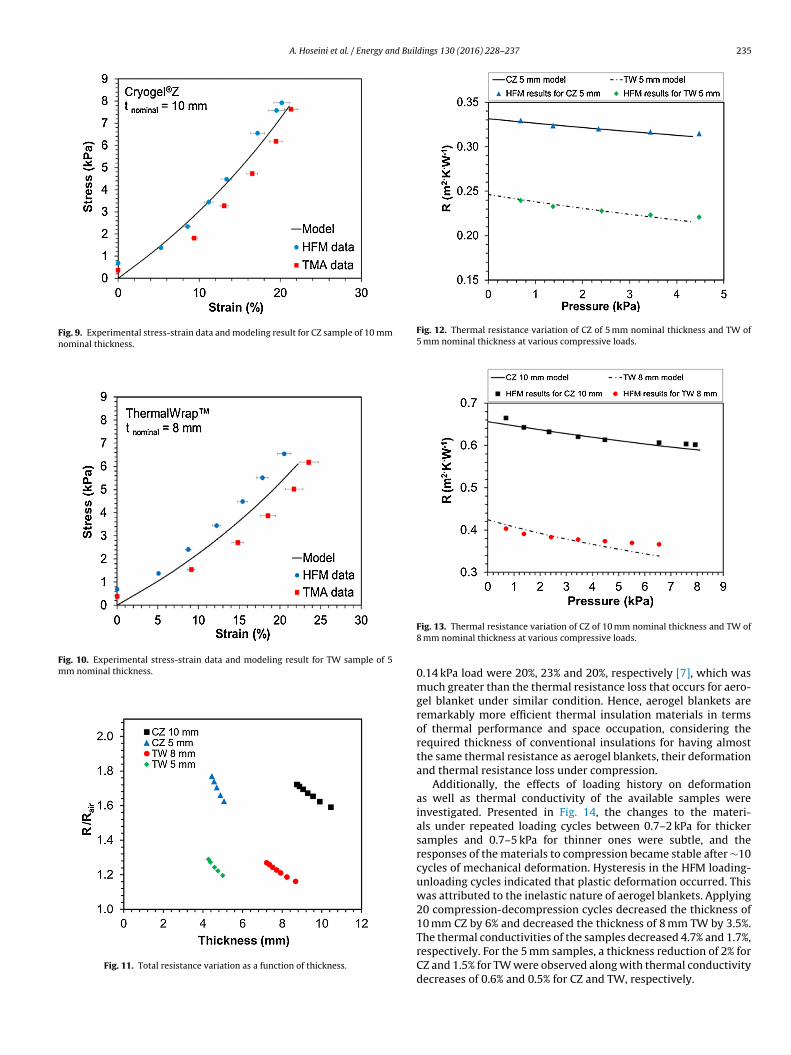
A new nonlinear model was developed to predict the defor-mation of aerogel blanket material as a function of the appliedmechanical load. Figs. 7–10 present the results of the experimentsperformed by HFM and TMA and comparison to the developedmodel. The results of the proposed approach agreed well with theexperimental data with low relative difference (maximum 10%) andshow that compression had minimal effect on the aerogel blanketinsulation materials compared to conventional insulation materi-als, e.g. cellulose, rock wool and fiberglass. In Ref. [7], large strainwere measured under relatively low loads. The authors reported40% strain in fiberglass, 26% strain in rock wool and 20% strain incellulosic insulation material, after applying maximum of 0.14 kPaon the samples with initial thickness of 30 cm.
Fig. 11 demonstrates the experimental measured thermal resis-tance for all the samples as a function of their thickness under
various loading conditions. The R-values were obtained at reducedthicknesses without removing the insulation specimen from theHFM. The maximum load that HFM can apply on samples dependson two factors: 1) the compression load cannot be greater than
234 A. Hoseini et al. / Energy and Buildings 130 (2016) 228–237
Fig. 6. Porosity modification algorithm.
Fn
2tdlmisest
ti
kaht
ig. 7. Experimental stress-strain data and modeling result for CZ sample of 5 mmominal thickness.
1 kPa; 2) the combined thickness of the specimen, the heat fluxransducer and any damping material, which in total equals theistance between the cold and hot plates, must be controlled to be
arge enough in order to minimize the effect of edge losses on theeasurement of heat flux [19]. Each specimen was tested under
ncreasing loads to the minimum allowed sample thickness. Thetandard deviation of the total resistances determined from thexperimental results were less than 10−4 m2 ◦C W−1. The relation-hip between total thermal resistance, thickness and the effectivehermal conductivity is as follows:
Rtoti= tb,i
keff ·Asamplei = 1, 2 (13)where keff represents the effective
hermal conductivity and Asample is the surface area of the samplen contact with the plates, respectively.
The relationship for predicting the deformation of aerogel blan-
et can be extended to predict the thermal resistance of the samplest various compressions (Eq. (13)). The thickness can be calculatedaving the deformation and porosity at each loading and for thehermal conductivity the analytical relationship for calculating the
Fig. 8. Experimental stress-strain data and modeling result for TW sample of 5 mmnominal thickness.
thermal conductivity of aerogel blankets from our previous studywas used [20]. Therefore, the thermal conductivity coefficient, keff ,is calculated using Eq. (14), which is calculated from the presentedmodel in ref. [20]:
keff = kcond. + krad. (14)
Fig. 12 and Fig. 13 demonstrate the variation of the thermalresistances as a function of compressive load for four different sam-ples, which are predicted well with the modeling. Results show thatwhen the compression load was increased from 0.7 kPa to 4.5 kPa,the resistance decreased 8.5% for CZ and 9% for TW for 5 mm thicksamples. These values for samples with higher thickness were 10%and 8.5% for CZ and TW, respectively. Hence, it can be concludedthat thermal resistance reduction in aerogel blanket insulation can
be as high as 8%, under ∼7 kPa compression, which is only due tomechanical deformation, i.e. thickness reduction. For rock wool,cellulose and fiberglass were shown that the resistance reduction,from full thickness condition of 30 cm, after applying just about
A. Hoseini et al. / Energy and Buildings 130 (2016) 228–237 235
Fig. 9. Experimental stress-strain data and modeling result for CZ sample of 10 mmnominal thickness.
Fig. 10. Experimental stress-strain data and modeling result for TW sample of 5mm nominal thickness.
Fig. 11. Total resistance variation as a function of thickness.
Fig. 12. Thermal resistance variation of CZ of 5 mm nominal thickness and TW of5 mm nominal thickness at various compressive loads.
Fig. 13. Thermal resistance variation of CZ of 10 mm nominal thickness and TW of8 mm nominal thickness at various compressive loads.
0.14 kPa load were 20%, 23% and 20%, respectively [7], which wasmuch greater than the thermal resistance loss that occurs for aero-gel blanket under similar condition. Hence, aerogel blankets areremarkably more efficient thermal insulation materials in termsof thermal performance and space occupation, considering therequired thickness of conventional insulations for having almostthe same thermal resistance as aerogel blankets, their deformationand thermal resistance loss under compression.
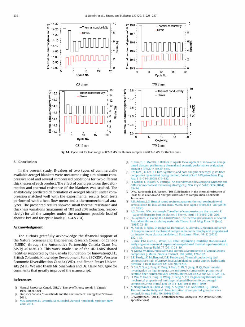
Additionally, the effects of loading history on deformationas well as thermal conductivity of the available samples wereinvestigated. Presented in Fig. 14, the changes to the materi-als under repeated loading cycles between 0.7–2 kPa for thickersamples and 0.7–5 kPa for thinner ones were subtle, and theresponses of the materials to compression became stable after ∼10cycles of mechanical deformation. Hysteresis in the HFM loading-unloading cycles indicated that plastic deformation occurred. Thiswas attributed to the inelastic nature of aerogel blankets. Applying20 compression-decompression cycles decreased the thickness of10 mm CZ by 6% and decreased the thickness of 8 mm TW by 3.5%.The thermal conductivities of the samples decreased 4.7% and 1.7%,
respectively. For the 5 mm samples, a thickness reduction of 2% forCZ and 1.5% for TW were observed along with thermal conductivitydecreases of 0.6% and 0.5% for CZ and TW, respectively.
236 A. Hoseini et al. / Energy and Buildings 130 (2016) 228–237
for th
5
aptmappltta
A
t(AfBEsc
R
[
[
[
[
[
[
[
[
Fig. 14. Cycle test for load range of 0.7–2 kPa
. Conclusion
In the present study, R-values of two types of commerciallyvailable aerogel blankets were measured using a minimum com-ressive load and several compressed conditions for two differenthicknesses of each product. The effect of compression on the defor-
ation and thermal resistance of the blankets was studied. Thenalytically predicted deformation of aerogel blanket under com-ression matched well with the experimental results from testserformed with a heat flow meter and a thermomechanical ana-
yzer. The presented results showed small thermal resistance andhickness variations (maximum of 10% and 20% reduction, respec-ively) for all the samples under the maximum possible load ofbout 8 kPa and for cyclic loads (0.7–4.5 kPa).
cknowledgment
The authors gratefully acknowledge the financial support ofhe Natural Sciences and Engineering Research Council of CanadaNSERC) through the Automotive Partnership Canada Grant No.PCPJ 401826-10. This work made use of the 4D LABS shared
acilities supported by the Canada Foundation for Innovation(CFI),ritish Columbia Knowledge Development Fund (BCKDF), Westernconomic Diversification Canada (WD), and Simon Fraser Univer-ity (SFU). We also thank Mr. Sina Salari and Dr. Claire McCague foromments that greatly improved the manuscript.
eferences
[1] Natural Resources Canada (NRC), “Energy efficiency trends in Canada
1990–2009,” 2011.
[2] Statistics Canada, “Households and the environment: energy Use,” Ottawa,2011.
[3] M.A. Aegerter, N. Leventis, M.M. Koebel, Aerogel Handbook, Springer, NewYork, 2011.
[
inner samples and 0.7–5 kPa for thicker ones.
[4] C. Buratti, E. Moretti, E. Belloni, F. Agosti, Development of innovative aerogelbased plasters: preliminary thermal and acoustic performance evaluation,Sustain 6 (9) (2014) 5839–5852.
[5] C.Y. Kim, J.K. Lee, B.I. Kim, Synthesis and pore analysis of aerogel-glass fibercomposites by ambient drying method, Colloids Surf. A Physicochem. Eng.Asp. 313–314 (2008) 179–182.
[6] H. Maleki, L. Durães, A. Portugal, An overview on silica aerogels synthesis anddifferent mechanical reinforcing strategies, J. Non. Cryst. Solids 385 (2014)55–74.
[7] D.W. Yarbrough, J. ti. Wright, (1981). Reduction in the thermal resistance ofloose fill insulation and fiberglass batts due to compression, CookevilleTennessee.
[8] R.D. Adams, J.G. Hust, A round robin on apparent thermal conductivity ofseveral loose-fill insulations, Insul. Mater. Test. Appl. (1990) 263–289 (ASTMSTP 1030).
[9] R.S. Graves, D.W. Yarbrough, The effect of compression on the material R−value of fiberglass batt insulation, J. Therm. Insul. 15 (1992) 248–260.
10] J.G. Symons, V. Clarke, R.E. ClarkePeirce, The thermal performance of severalAustralian fibrous insulating materials, Therm. Insul. bldg. Envs. 19 (July)(1995) 72–88.
11] M. Kolich, P. Hoke, D. Dooge, M. Doroudian, E. Litovsky, J. Kleiman, Influenceof temperature and mechanical compression on thermophysical properties ofcar interior foam plastics insulation, J. Elastomers Plast. 46 (2) (2014)132–143.
12] E. Cuce, P.M. Cuce, C.J. Wood, S.B. Riffat, Optimizing insulation thickness andanalysing environmental impacts of aerogel-based thermal superinsulation inbuildings, Energy Build. 77 (2014) 28–39.
13] N. Gupta, W. Ricci, Processing and compressive properties of aerogel/epoxycomposites, J. Mater. Process. Technol. 198 (2008) 178–182.
14] E.R. Bardy, J.C. Mollendorf, D.R. Pendergast, Thermal conductivity andcompressive strain of aerogel insulation blankets under applied hydrostaticpressure, J. Heat Transfer 129 (2) (2007) 232.
15] D. Shi, Y. Sun, J. Feng, X. Yang, S. Han, C. Mi, Y. Jiang, H. Qi, Experimentalinvestigation on high temperature anisotropic compression properties ofceramic-fiber-reinforced SiO2 aerogel, Mater. Sci. Eng. A 585 (2013) 25–31.
16] H. Wu, Y. Liao, Y. Ding, H. Wang, C. Peng, S. Yin, Engineering thermal andmechanical properties of multilayer aligned fiber-reinforced aerogelcomposites, Heat Transf. Eng. 35 (11–12) (2014) 1061–1070.
17] A. Neugebauer, K. Chen, A. Tang, A. Allgeier, L.R. Glicksman, L.J. Gibson,
Thermal conductivity and characterization of compacted, granular silicaaerogel, Energy Build. 79 (2014) 47–57.
18] L. Waguespack, (2013). Thermomechanical Analysis (TMA Q400EM/Q400specifications).
[23] “Thermal wrap data sheet,” no. i. p. 2011, (2011).
A. Hoseini et al. / Energy an
19] ASTM C518-10, (2010). Standard test method for steady-state thermaltransmission properties by means of the heat flow meter apparatus, ASTM,International, West Conshohocken, PA.
20] A. Hoseini, C. McCague, M. Andisheh-Tadbir, M. Bahrami, Aerogel blankets:from mathematical modeling to material characterization and experimentalanalysis, Int. J. Heat Mass Transf. 93 (2016) 1124–1131.