Energy-Aware SYstem-on-chip design of the HIPERLAN/2 standard IST-2000-30093 Title: Low-power bus encoding techniques Authors: Enrico Macii Editor: POLITO Document ID: EASY/WP3/POLITO/DL/P/D17/B1 Version: 5 Type: Deliverable Confidentiality: Public Status: Project Approved Date: September 21, 2002 Workpackage: 3 Keywords: Bus interface design, Low-power bus encoding Abstract: This deliverable evaluates the applicability of encoding techniques in the context of the design of low-power communication buses. The existing literature is reviewed in detail with the purpose of identifying the classes of bus encoding schemes that are most suitable to the EASY project, namely, those which are applicable in the context of the HIPERLAN/2 SoC development. Several algorithms have been implemented to allow a meaningful comparison of different encoding methods, and thus enable a first screening of the techniques that could then be applied during the HIPERLAN/2 SoC development. Copyright 2002 ICOM POLITO UP FhG IIS-A STM IMEC AUTH
Transcript
Energy-Aware SYstem-on-chip design of the HIPERLAN/2 standard
IST-2000-30093
Title: Low-power bus encoding techniques
Authors: Enrico Macii
Editor: POLITO
Document ID: EASY/WP3/POLITO/DL/P/D17/B1
Version: 5
Type: Deliverable
Confidentiality: Public
Status: Project Approved
Date: September 21, 2002
Workpackage: 3
Keywords: Bus interface design, Low-power bus encoding
Abstract:
This deliverable evaluates the applicability of encoding techniques in the context ofthe design of low-power communication buses. The existing literature is reviewed indetail with the purpose of identifying the classes of bus encoding schemes that aremost suitable to the EASY project, namely, those which are applicable in the contextof the HIPERLAN/2 SoC development. Several algorithms have been implemented toallow a meaningful comparison of different encoding methods, and thus enable a firstscreening of the techniques that could then be applied during the HIPERLAN/2 SoCdevelopment.
Copyright 2002
ICOMPOLITOUPFhG IIS-ASTMIMECAUTH
IST-2000-30093 Low-power bus encoding techniques
EASY/WP3/POLITO/DL/P/D17/B1 Public 2
History
Date Version Comments
August 13, 2002 1 First draft
August 29, 2002 2 Added survey section
September 12, 2002 3 Added experimental results
September 18, 2002 4 Version submitted to Consortium
September 21, 2002 5 Project Approved
IST-2000-30093 Low-power bus encoding techniques
EASY/WP3/POLITO/DL/P/D17/B1 Public 3
Table of contents
LIST OF TABLES AND FIGURES..................................................................................................................4
2. BUS ENCODING FOR LOW POWER ..............................................................................................5
3. SURVEY OF LOW-POWER BUS ENCODING TECHNIQUES .....................................................73.1 SWITCHING ACTIVITY REDUCTION TECHNIQUES ..............................................................................83.2 COUPLING ACTIVITY REDUCTION TECHNIQUES..............................................................................11
4. EXPERIMENTAL RESULTS ..........................................................................................................134.1 CURRENT LIMITATIONS OF THE EXPLORATION FRAMEWORK........................................................16
5. BUS ENCODING IN THE THE EASY HIPERLAN/2 CHIP..........................................................17
FIGURE 1: CONCEPTUAL SCHEME OF BUS ENCODING. ............................................................................6TABLE 1. LOW-POWER BUS ENCODING SPACE. ......................................................................................7FIGURE 2: GENERIC ENCODING TEMPLATE. ..........................................................................................11TABLE 2. CHARACTERISTICS OF THE ADDRESS TRACES. ......................................................................13TABLE 3. CHARACTERISTICS OF THE DATA TRACES. ............................................................................13FIGURE 3: ENERGY SAVINGS ON ADDRESS STREAMS. ..........................................................................14FIGURE 4: ENERGY SAVINGS ON DATA STREAMS. ................................................................................15FIGURE 5: AVERAGE ENERGY SAVINGS ON ADDRESS STREAMS. .........................................................15FIGURE 6: AVERAGE ENERGY SAVINGS ON DATA STREAMS. ...............................................................16FIGURE 7: ARCHITECTURAL TEMPLATE OF THE EASY SOC.................................................................17FIGURE 8: ARCHITECTURE OF THE BASE-BAND AND LOWER-LEVEL MAC PROCESSING SYSTEM. .....17
IST-2000-30093 Low-power bus encoding techniques
EASY/WP3/POLITO/DL/P/D17/B1 Public 5
1. INTRODUCTION
The purpose of this document is to evaluate the applicability of energy-efficient bus encodingtechniques within the architecture of the EASY SoC. In particular, we will discuss what techniques aresuitable for implementation, and where (i.e., in which buses of the chip) these techniques are likely tobe more successful.
Although many low-power bus encoding techniques have been proposed in the literature, theircomparison is almost unfeasible, because of the different technological assumptions and the differenttraces used for their evaluation. In order to provide a comprehensive, yet meaningful exploration ofthe various encoding schemes, this document contains:
§ An extended survey of the most effective bus encoding techniques proposed by the researchcommunity.
§ Experimental results on the effectiveness of the surveyed schemes, evaluated with theirpreliminary software implementation.
The EASY SoC platform is obviously just one possible application of this analysis. The technologicaland front-end assumptions are so general that a more integrated version of the software explorationtool will be developed in the second half of the workplan, as it will hold reasonable chances forexploitation beyond the boundaries of the project.
The document is organized as follows. Section 2 discusses the general paradigm of bus encoding forlow power, and it includes a brief overview of the most commonly adopted bus power models. Section3 contains the survey of the bus encoding methods existing in the literature, and it provides anapproach to their classification. Section 4 is devoted to the analysis of some preliminary experimentalresults obtained on some bus traces. The data have been collected through a ``quick-and-dirty’’implementation of most of the surveyed encoding schemes. Although the exploration framework is notyet complete, the existing software has allowed us to come up with some useful observations and hintsabout the usability of bus encoding in the context of the EASY chip design. The report closes withSection 5, which analyzes the relation between the proposed optimization schemes and the EASYplatform, highlighting where and how bus encoding could be applied in practice during the Hiperlan/2SoC development.
2. BUS ENCODING FOR LOW POWER
Two different levels of encoding can be applied on the information transmitted on a bus: Signalencoding and data encoding. The former consists of modifying (in time or space) the way the binary0’s and 1’s are represented. For instance, a 1 could be represented as a 0->1 transition. The latter typeof encoding consists of modifying the way the binary words are represented. For instance, a wordcould be represented by adding one parity bit.
The application of the two types of encoding is not mutually exclusive. However, signal encodingtends to have an impact on the technology used to implement the design. For instance, a typical signalencoding technique consists of reducing the voltage swing on (possibly some) bus wires. To make thispossible, the technology on which the system will be implemented must be able to support that voltagelevel. For this reason, signal encoding techniques are not suitable for application in the context of theEASY architecture, and will not be analyzed further. Conversely, data encoding has more generalvalidity, since the only underlying assumption is that of tolerating the insertion of additional hardwareto perform the various encodings.
IST-2000-30093 Low-power bus encoding techniques
EASY/WP3/POLITO/DL/P/D17/B1 Public 6
Bus encoding is typically used to improve performance or, more recently, to reduce the powerdissipated on the bus lines. In particular, bus encoding has shown to be a very effective technique forpower reduction, because even on-chip bus lines have relatively large parasitic capacitance, comparedto cell capacitance. Buses are in fact a significant source of power in today’s systems: For example, ithas been measured that they may account for up to 30% of the total power in a modernmicroprocessor. Therefore, the relative impact of a significant energy reduction on a bus is nonnegligible.
Another reason for the popularity of low-power encoding schemes is the relative simplicity of the busenergy model. For a bus with n lines (each one having a capacitance C), and under a supply voltageVdd, the total energy consumed by the bus for a computation of Ncycles cycles is:
Ebus = Ncycles n C V2dd (1)
The average power can be simply obtained by multiplying Ebus by f, the frequency at which the busoperates. Equation 1 assumes that, for each cycle, all of the n bus lines exhibit a transition that causesthe corresponding capacitance to switch. In general, not all the lines will switch, so that a cycle-basedmodel is more accurate, as in Equation 2:
Ebus = (Σ i=0…Ncycles ni ) C V2dd = ntot C V2
dd (2)
where ni is the number of lines switching at each cycle, also called the Hamming distance between twoconsecutive words transmitted on the bus.
Given this model, the only real degree of freedom for reducing energy consumption is ni. As a matterof fact, Ncycles depends on the application running on the processor, while C and Vdd depend on thetechnology, which we must consider as given. Therefore, most bus encoding techniques are based onthe idea of reducing the switching activity of a bus, i.e., the value of ntot.
Inserting proper encoders and decoders at the sender and receiver’s end of the bus achieve reduction ofthe switching activity. This scheme implies point-to-point buses, as conceptually depicted in Figure 1.In the sequel, we will refer for brevity to the combination of the encoder and of the decoder as thecodec.
FIGURE 1: CONCEPTUAL SCHEME OF BUS ENCODING.
When comparing the energy efficiency of various encoding schemes, it is essential to consider also theimpact of the codec in the resulting power budget (in addition to timing and latency overheads).Codecs will obviously consume energy, which should not offset the power reduction achieved byreducing the total number of transitions.
IST-2000-30093 Low-power bus encoding techniques
EASY/WP3/POLITO/DL/P/D17/B1 Public 7
3. SURVEY OF LOW-POWER BUS ENCODING TECHNIQUES
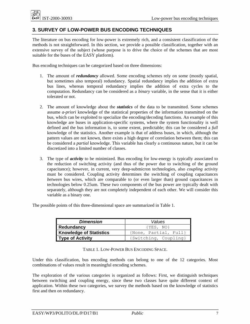
The literature on bus encoding for low-power is extremely rich, and a consistent classification of themethods is not straightforward. In this section, we provide a possible classification, together with anextensive survey of the subject (whose purpose is to drive the choice of the schemes that are mostsuitable for the buses of the EASY platform).
Bus encoding techniques can be categorized based on three dimensions:
1. The amount of redundancy allowed. Some encoding schemes rely on some (mostly spatial,but sometimes also temporal) redundancy. Spatial redundancy implies the addition of extrabus lines, whereas temporal redundancy implies the addition of extra cycles to thecomputation. Redundancy can be considered as a binary variable, in the sense that it is eithertolerated or not.
2. The amount of knowledge about the statistics of the data to be transmitted. Some schemesassume a-priori knowledge of the statistical properties of the information transmitted on thebus, which can be exploited to specialize the encoding/decoding functions. An example of thisknowledge are buses in application-specific systems, where the system functionality is welldefined and the bus information is, to some extent, predictable; this can be considered a fullknowledge of the statistics. Another example is that of address buses, in which, although thepattern values are not known, there exists a high degree of correlation between them; this canbe considered a partial knowledge. This variable has clearly a continuous nature, but it can bediscretized into a limited number of classes.
3. The type of activity to be minimized. Bus encoding for low-energy is typically associated tothe reduction of switching activity (and thus of the power due to switching of the groundcapacitance); however, in current, very deep-submicron technologies, also coupling activitymust be considered. Coupling activity determines the switching of coupling capacitancesbetween bus wires, which are comparable to (or even larger than) ground capacitances intechnologies below 0.25um. These two components of the bus power are typically dealt withseparately, although they are not completely independent of each other. We will consider thisvariable as a binary one.
The possible points of this three-dimensional space are summarized in Table 1.
Dimension ValuesRedundancy {YES, NO}Knowledge of Statistics {None, Partial, Full}Type of Activity {Switching, Coupling}
TABLE 1. LOW-POWER BUS ENCODING SPACE.
Under this classification, bus encoding methods can belong to one of the 12 categories. Mostcombinations of values result in meaningful encoding schemes.
The exploration of the various categories is organized as follows: First, we distinguish techniquesbetween switching and coupling energy, since these two classes have quite different context ofapplication. Within these two categories, we survey the methods based on the knowledge of statisticsfirst and then on redundancy.
IST-2000-30093 Low-power bus encoding techniques
EASY/WP3/POLITO/DL/P/D17/B1 Public 8
3.1. Switching activity reduction techniques
3.1.1. No knowledge of statistics
3.1.1.1. Irredundant codes
Assuming no knowledge about the statistics of the bus to be transferred is equivalent to assuming thatthe data stream sent on the bus is random white noise (RWN), i.e., it has maximum entropy rate.Under this assumption, it can be shown that switching activity can be decreased through the additionof redundancy, because all irredundant codes have the same switching activity [1]. Although thetheory shows that some redundancy is necessary to decrease switching, some methods do not assumeany knowledge about the statistics and still achieve energy reduction. This is possible by constructingstatistical information on-the-fly. These adaptive methods differ in the way information is gathered.
In the scheme of [2], the symbols to be transmitted are stored in a data structure called self-organizinglist, which is actually a table. The encoder transmits table indices instead of actual words; switchingreduction is achieved by pushing frequently occurring values to the front of this list. Synchronizationbetween encoder and decoder is guaranteed by the use of the same organization criterion in the list.This method provides significant savings for data and multiplexed buses, where correlation is notpredictable, although with a significant overhead, when applied to the entire bus word.
Another adaptive encoding scheme is described in [3]; it is developed within a more generalinformation-theoretic framework that will be discussed later in this document. This method is based onthe construction of approximate statistics on the fly; statistics are computed at the bit level, thussacrificing accuracy to ensure the feasibility of a physical implementation of the codec. Statistics arecollected by observation of the bit stream over a window of fixed size (typically 32-64 bits), and areused to select among a set of bit-wise encoding functions that minimize the switching. This scheme isactually non-redundant; energy savings are achieved through this local, approximate construction ofthe statistics.
3.1.1.2. Redundant codes
Redundant schemes are based on the addition of extra control wires to the bus. This can be seen asextending the word's width by one or more redundant bits. These bits inform the receiver about howthe data were encoded before the transmission.
A conceptually simple and powerful scheme was proposed by Stan and Burleson [4], and called Bus-Invert (BI) encoding. To reduce the switching, the transmitter computes the Hamming distancebetween the word to be sent and the previously transmitted one. If the distance is larger than half theword width, the word to be transmitted is inverted, i.e., complemented. The “bus-invert” informationis carried by an additional wire, which is used at the receiver end to restore the original data.
This encoding scheme has some interesting properties. First, the worst-case number of transitions ofan n-bit bus is n/2 at each time frame. Second, if we assume that data are uniformly randomlydistributed, it is possible to show that the average number of transitions with this code is lower thanthat of any other encoding scheme with just one redundant line. Moreover, the basic 1-bit redundantbus-invert code has the property that the average number of transitions per line increases as the busgets wider, and asymptotically converges to 0.5, which is also the average switching per line of anunencoded bus, and is already close to this value for 32-bit busses.
This drawback has spun a number of variants of the basic BI scheme, based on the partitioning of thebus into smaller blocks, and on the use of bus inversion on each block independently [5]-[9]. Since thetrivial application of this partitioned variant on a m-block bus would require m control lines, thesemethods have tried to reduce this additional complexity. Notice that, from the theoretical point ofview, the m-bit bus invert code is no longer optimal among all the possible m-redundant codes,although it keeps a reasonable complexity.
IST-2000-30093 Low-power bus encoding techniques
EASY/WP3/POLITO/DL/P/D17/B1 Public 9
Other extensions to the bus invert encoding approach include the use of limited-weight codes andtransition signaling. A k-limited-weight code is a code having at most k 1's per word. This can beachieved by adding appropriate redundant lines [10]. Such codes are useful when used in conjunctionwith transition signaling, i.e., with schemes where 1's are transmitted as a 0-1 (or 1-0) transition and0's by the lack of a transition. Thus, a k-limited-weight code would guarantee at most k transitions percycle (plus the transitions on the redundant lines).
Other examples of this class of encodings are the codebook-based schemes, which could be viewed asgeneralized invert schemes [11]. In these methods, a data word is compared with all the code datastored in a codebook to find the code with the minimum Hamming distance, which is transmitted overthe bus, and the redundant wires are used to carry the Hamming distance value. Variants of this basicscheme consider the possibility of updating the codebook (at the sender and receiver’s end) or the useof transition-based encodings. The complexity of the codecs is usually high, because they requirestoring the codebook table.
A similar approach is followed in the frequent-value (FV) encoding [12], that is based on the cacheprinciple: Frequently occuring values are transmitted in the encoded form, whereas infrequent valuesare left unencoded. The set of frequent values are stored in a CAM that must exist at both ends of thebus. Redundant wires are used to distinguish encoded values from unencoded ones, and to keep theCAMs consistent, especially in the case of a replacement. Codec overhead is considerable, especiallyfrom the timing point of view.
3.1.2. Partial knowledge of statistics
By partial knowledge we mean that statistics are known as a general property of the bus data; in otherwords, we do not require the knowledge of the specific data stream (values, or even addresses). Thistypically applies to address buses, which exhibit well-known correlations between consecutiveaddresses, regardless of their specific values. In particular, addresses generated by processors typicallyexhibit a high degree of sequentiality; this is particularly true for data-dominated applications, wherethe few control structures only occasionally break the sequentiality of the address stream.
3.1.2.1. Irredundant codes
Some authors have suggested the adoption of the Gray coding [13],[14] as encoding strategy. Thiscode achieves its asymptotic best performance of a single transition per emitted address when infinitestreams of consecutive addresses are considered, and it is optimum only in the class of irredundantcodes.
The Encoding Zone (EZ) is a class of irredudant schemes that exploit the locality aspects of thesequentiality of address streams [15]. In particular, it encodes an address based on the zone it belongs.The base scheme assumes two zones, whose values are stored in two registers. To encode an N-bitaddress, its offset is computed with respect to both zone registers. The encoding is done using the zonethat yields the smaller offset. This offset is translated to N-1 bits and then concatenated with a singlebit which identifies the zone register, that is, the encoding is done by using N bits and there is no needto provide an additional line for identifying the zone register that is used. Values stored in the zoneregisters are changed dynamically to update the zones.
Another irredundant set of codes suitable for address buses is proposed in [16]. These are small, yeteffective variations of previously developed (but redundant) schemes. Irredundancy is achievedthrough the decorrelating characteristics of the exclusive OR (XOR) function, when applied toconsecutive bus patterns. In this way, the values on the bus are encoded using a transition signalingscheme.
IST-2000-30093 Low-power bus encoding techniques
EASY/WP3/POLITO/DL/P/D17/B1 Public 10
3.1.2.2. Redundant codes
As for the maximum entropy case, redundant codes are based on the addition of extra bus lines. Suchredundancy clearly allows more significant energy reductions, at the expense of more complex codecs.The T0 code [17] uses an extra bus line INC to signal when a pair of consecutive addresses is writtento the bus. When INC is high, the current bus value is frozen to avoid unnecessary switching, and thenew address is computed directly by the receiver. On the other hand, when two addresses are notconsecutive, the INC line is low, and the bus operates normally. Several variants of the T0 code arepossible, some of which may incorporate the Bus-Invert principle to exploit distinctive spectralcharacteristics of the streams being transmitted [18].
The high sequentiality of address streams is at the basis of the effectiveness of encoding mechanismssuch as Gray and T0. Clearly, if the percentage of in-sequence addresses decreases, their effectivenessdiminishes as well.
The Working Zone (WZ) code [19] is based on the observation that many programs access multipledata arrays. The accesses to each array are mostly sequential, but often interleaved; in such cases, thesequentiality on the bus is destroyed, because the temporal correlation only applies for a short numberof cycles. The Working Zone scheme restores sequentiality by storing the reference addresses of eachworking zone on the receiver side and by sending only the highly sequential offsets. Whenever thedata access moves to a new working zone, this information is communicated to the receiver with aspecial code word. The receiver changes the default reference address and offset transmission canresume. The number of working zones determines the number of extra bus lines: for N zones, log2Nextra lines are required. Although this scheme is more flexible than Gray and T0, it still relies onstrong assumptions on the patterns in the stream. For instance, if the data access policy is not array-based, or if the number of working zones is too large, this encoding scheme loses its effectiveness.
The Beach code [20] targets more complex types of correlations. For instance, it has beenexperimentally observed that consecutive addresses often show significant block correlations, that is,the sequential patterns are actually observable on a subset of the bus lines. Clearly, determining anencoding strategy able to capture this statistics depends on the specific stream being transmitted,therefore, the Beach scheme should more properly be classified among the methods that assume fullknowledge of the statistics. However, as an address bus encoding scheme, it is discussed in thissection. Given a typical execution trace of the address bus to be encoded, statistical informationidentifying possible block correlations is collected. The bus lines are then grouped into clustersaccording to their correlations, that is, lines belonging to the same cluster are highly correlated. Anencoding function is automatically generated for each cluster, and each configuration of bits in theoriginal cluster is translated into a new bit configuration.
3.1.3. Complete knowledge of statistics
Many encoding schemes rely on a complete characterization of the statistical properties of the data.This characterization is a well-established operation in the information theory domain: It can beformally denoted with a discrete function fK(w1,w2,…,wK) → [0; 1], where the input domain is the setof K-tuples of input symbols to be transmitted, and the output value is the probability of each symbol.Practical reasons limit the value of K to a maximum of 2 (i.e., the second-order statistics). Given theknowledge of f, the encoder (and the decoder) that minimizes average switching activity can beobtained as specializations of a basic encoding template, shown in Figure 2. The decoder takes asinput one encoded word and I previously-decoded words, and outputs the original unencoded symbolx(n). A decorrelator-correlator pair (DECOR) can optionally be inserted between the encoder-decoderpair and the bus. This circuit has the only purpose of mapping ones in y(n) into transitions on the buslines, and vice versa. It is used because it translates the problem of minimizing the number oftransitions into the problem of minimizing the number of ones.
IST-2000-30093 Low-power bus encoding techniques
EASY/WP3/POLITO/DL/P/D17/B1 Public 11
FIGURE 2: GENERIC ENCODING TEMPLATE.
Ramprasad et al. [1] describe a number of encoding schemes around a simplified version of thetemplate. Although the template is meant for a fully characterized source (i.e., the distribution of allthe bus data values is known), simpler schemes (e.g., BI) can be represented as special cases of thistemplate. From the point of view of practical applicability, it is important to discuss how realistic isthe assumption about the full characterization of the source. In that respect, this assumption applies (atleast in part) to application-specific, embedded systems where a dedicated core repeatedly executes thesame set of applications; this allows to extract at least a partial statistical characterization, obtained byexercising the system to extract a typical behavior.
Because of the requirement of such statistical information, methods belonging to this class proposed inthe literature are typically irredundant.
Benini et al. [3] propose a procedure for building optimum codes (under the template of Figure 2) for agiven second-order statistics, using one previously decoded word (I=1). The algorithm provides anupper bound of the transition reduction achievable under these assumptions. It is based on sortingconsecutive pattern pairs (x(n), x(n-1)) in non-increasing order of occurrence; minimum weight (i.e.,with as few 1’s as possible) codes are assigned in strict order, starting from the most frequent pair. Theinteresting point is that different pairs may be assigned the same code, as long as its decodability isguaranteed. This encoding scheme has just theoretical interest, because its implementation isunfeasible for realistic bus widths. To make it applicable in practice, approximate solutions have beenproposed by the same authors. One variant uses clustering to divide the wide bus into several smallerclusters, on which the algorithm is applied. Another variant limits the application of the algorithm tothe M most probable pairs (with M much smaller than the complete alphabet space).
3.2. Coupling activity reduction techniques
Minimizing the switching activity on a bus reduces energy by decreasing the number switchings of thecapacitance between each bus line and the ground (called self-capacitance). From an energetic pointof view this is not the only capacitance that switches. Inter-wire (or crosstalk) capacitances switchwhen two simultaneous, opposite transitions on adjacent bus lines occur.
In very deep submicron (DSM) technologies (below 0.25µm), these capacitances become larger thanself capacitances, thus assuming a dominant effect on the total energy required by buses to transferinformation across a chip. As a consequence, low-power bus encoding techniques need to be enhancedto account for this additional contribution to the capacitances that are charged and discharged duringcommunication.
IST-2000-30093 Low-power bus encoding techniques
EASY/WP3/POLITO/DL/P/D17/B1 Public 12
In presence of coupling capacitances, the energy model modifies as follows:
Ebus = nsw,tot Cs V2
dd + ncsw,tot Cx V2
dd (3)
where nsw,tot is the total number of bit switchings over the total transmission time, and ncsw,tot is thetotal number of simultaneous, opposite transitions. Cs and Cx are the self and crosstalk capacitance perline and line pair, respectively.
The topic of bus encoding for crosstalk energy reduction is relatively new, and only a small number ofworks are available in the literature, that does not justify a detailed classification as for switchingactivity-oriented methods.
Most of these approaches tackle crosstalk bus energy by minimizing the number of simultaneoustransitions on adjacent bus lines. The majority of these methods encodes the data sent on the busthrough explicit encoders [21]-[24] and does not assume any knowledge of the statistics. In some cases[21], redundancy is used to improve the efficiency of the encoding.
Other schemes are intrinsically irredundant, and are based on the swapping of some “critical” bus linesduring layout[25],[26]. Swapping results in moving critical wires far apart, thus exploiting the roughlyinversely proportional dependence of Cx on the distance between a pair of wire. Clearly, theidentification of the critical wires implies that the bus trace can be somehow “observed”; therefore,these schemes assume some knowledge about the statistics of the data. The method of [26] targetsaddress buses, because it relies on approximate information, while [25] is suitable for application-specific systems since it makes stronger assumptions on statistics.
All these solutions share a common limitation, which makes them little appealing to physicaldesigners. In some sense, they tackle the wrong problem: They aim at reducing crosstalk byminimizing the number of simultaneous transitions. While this may be a way to reduce crosstalkpower, it does not reduce crosstalk by itself. Crosstalk mainly affects signal integrity, and even asensible reduction of crosstalk-induced power is of little interest for designers, if it does not guaranteethe proper functionality of the design. Therefore, a proper solution of the problem must be consistentwith typical performance-oriented crosstalk reduction techniques. In other terms, since crosstalk ismainly a capacitive effect, the only way to reduce it is that of reducing the capacitance causing it, andlet energy reduction come as a by-product. The method introduced in [27] presents a first step in thatdirection; here, wire spacing is properly used to generate a bus layout whose wires have non-uniformdistance. Spacing between wires is customized against the statistical characteristics of the bus stream(specifically, addresses). Technically speaking, such methods tend to belong more to the physicaldesign domain, than to the conventional notion of “encoding”.
IST-2000-30093 Low-power bus encoding techniques
EASY/WP3/POLITO/DL/P/D17/B1 Public 13
4. EXPERIMENTAL RESULTS
In order to assess in a rigorous way their actual effectiveness, we have implemented some of thereviewed bus encoding methods in software, using the description given in the original papers. Themethods have been validated on a set of traces consisting of six address traces and nine data traces,whose characteristics are described Tables 2 and 3.
Address traces have been otained by profiling the corresponding applications on a ARM-basedarchitecture, using the ARM SDK. Data traces have been simply obtained by splitting thecorresponding binary or data file into chunks of size equal to the width of the bus. In all tests, we haveassumed 32 bus lines, as supported by the ARM architecture.
Name Length DescriptionCountSkip 11994 Artificial sequence of addresses consisting of a sequence of
Counter 98119 Artificial perfect sequence of addresses (counts from 0 to 90K)DCT 7514 Address trace of the Discrete Cosine TransformDashBoard 232103 Address trace of an automotive control applicationFFT 14959 Address trace of the Fast Fourier TransformMM 15736 Address trace of a row-by-column matrix multiplication
algorithm
TABLE 2. CHARACTERISTICS OF THE ADDRESS TRACES.
Name Length DescriptionDCT 2307 Binary of the Discrete Cosine TransformDashBoard 23606 Binary of an automotive control applicationFFT 3226 Samples of a Fast Fourier TransformHTML 22534 Web pageM31 90915 Image in the PPM formatMP3 25600 Audio file in MP3 formatBison 61440 Binary of the GNU Bison utilityFlex 79872 Binary of the GNU Flex utilityGcc 20480 Binary of the GNU gcc
TABLE 3. CHARACTERISTICS OF THE DATA TRACES.
The results consisted in the application of some of the surveyed schemes to all types of trace,regardless of their potential suitability. In other words, we have applied all methods to any type oftrace.
We have implemented 11 different encoding methods (BI, Gray, T0, T0-BI, Dual T0+BI, Beach,Working Zone, dbm-pbm, xor-pbm, Entropic encoding, Adaptive entropic encoding). Theimplementation of some of these methods (in particular, the Beach, the Adaptive, and the WorkingZone) has required a significant programming effort, since the original descriptions of these methodswere not always easily translatable into code.
IST-2000-30093 Low-power bus encoding techniques
EASY/WP3/POLITO/DL/P/D17/B1 Public 14
The choice of what methods to implement, among the many encoding methods described in Section 3,was based on one main criterion: The complexity of their codecs. The selection process has been doneon the basis of the data reported in the papers describing them; in some cases, this implied comparingenergy or delay figures in different technologies or different synthesis flows. For this reason, in mostcases (for instance, the many variants of the T0 scheme), we have chosen only the base techniquerather than more energy-efficient variants, because of their higher degree of complexity. The onlyexception to this criterion is the implementation of the three methods (dbm-pbm, xor-pbm, and theEntropic encoding), which are not practical encodings, and that have been considered for referencepurpose, for evaluating the absolute validity of the other schemes. The first two are taken from [1],while the latter refers to the entropic method of [3], described at the end of Section 3.1.3.
The reason why codec complexity was used as a criterion is due to the fact that we are evaluating thepossibility of applying some of these schemes to local, on-chip buses. Local buses are short (in theorder of 10-100 µm), and their line capacitances are then small, compared to off-chip buses. Smallerbus capacitances imply smaller absolute power figures; this leaves a smaller budget for the codec.
Encoding methods that target coupling activity have not been considered, because they requiretechnological details which are not really available at this time of the project, such as the targettechnology on which the EASY chip will be implemented. Thus, although crosstalk will definitely bean issue for the technology on which the EASY SoC will be implemented, any analysis orimplementation would be premature.
Figure 3 shows how the selected methods perform on address streams, in terms of percentage ofsavings in the number of transitions with respect to the unencoded trace. As already mentioned, wealso applied methods like the BI or the Adaptive code, which do not exploit correlation in any way.
FIGURE 3: ENERGY SAVINGS ON ADDRESS STREAMS.
IST-2000-30093 Low-power bus encoding techniques
EASY/WP3/POLITO/DL/P/D17/B1 Public 15
Figure 4 reports the results for data streams, while Figure 5 and Figure 6 summarize the results of theprevious charts by averaging over the various traces.
Some interesting facts can be observed from the plots. First, for data streams, all methods are quite farfrom the theoretical maximum saving. Second, the Adaptive scheme performs reasonably well acrossdifferent types of streams, both address and data ones, making it a good candidate for the applicationin the EASY platform, also thanks to its compact codec.
FIGURE 4: ENERGY SAVINGS ON DATA STREAMS.
FIGURE 5: AVERAGE ENERGY SAVINGS ON ADDRESS STREAMS.
IST-2000-30093 Low-power bus encoding techniques
EASY/WP3/POLITO/DL/P/D17/B1 Public 16
FIGURE 6: AVERAGE ENERGY SAVINGS ON DATA STREAMS.
4.1. Current limitations of the exploration framework
The current implementation of the various schemes should be considered as very preliminary, from thepoint of view of the integration. The methods are implemented as separate routines that can beinvoked from a main interactive interface. However, each method has many specific options that donot apply to other ones. Therefore, a rationalization effort must be done to fully explore thepotentiality of the various encoding schemes. Furthermore, the software is not very optimized: Theimplementation has been carried out incrementally, and in some cases (e.g., extraction of statistics)code reuse has been quite poor.
Second, and more important, the tool should be considered mostly as a software simulator. Noevaluation of the codec complexity is done. This is an important issue, but its integration requires theprecise knowledge of the synthesis flow, and of the technology. On the other hand, evaluation of thecomplexity of the codec (delay, energy, and area) is essential for a realistic use of these methods in areal-life architecture.
We believe that both the optimization and the integration of the codec synthesis feature will give thistool many opportunities for exploitation beyond the boundaries of the EASY project. This will be thesubject of our activities in the second half of the project.
.
IST-2000-30093 Low-power bus encoding techniques
EASY/WP3/POLITO/DL/P/D17/B1 Public 17
5. BUS ENCODING IN THE EASY HIPERLAN/2 CHIP
The purpose of this section is that of analyzing the potential sources of applicability of low-power busencoding techniques within the EASY chip. Figure 7 shows the top-level view of the proposedarchitectural template of the EASY SoC. The picture exposes three main buses:
§ A local bus, that connects the ARM core to a cache SRAM, a program ROM, an MMU,timers, an interrupt controller and an interface unit to another bus.
§ The main bus, where all other devices, including internal and external RAM, DMA, PCI andEthernet controller are connected; this is a AMBA AHB bus, which is also accessed by theARM core through the local bus and the AMBA AHB interface.
§ An I/O bus, that connects the main bus to external devices and the UART; this is an AMBAAPB bus, whose connection to the local bus is realized through a AHB/APB bus.
AMBA AHB
DMAController
SDRAMController
PCIController
ETHERNET
ControllerLocal Bus
AHB Bus I/F
ARMuP
CacheSRAM
MMUROM
AHB Bus I/F
Timers,W atchdog,InterruptController
ExternalMemory Bus PCI Bus
ETHERNETTransceiver
Test and debugController
TestPort
AHB Bus I/F AHB Bus I/F AHB Bus I/F AHB Bus I/F
PowerManagement
Baseband and
Lower- level MAC processing elements
:
AHB to APBbridge
APB bus
UART
Other I/Odevices
RF and
analog
front-end
FIGURE 7: ARCHITECTURAL TEMPLATE OF THE EASY SOC.
The base-band lower-level MAC processing unit, seen by the protocol processor as a device connectedto the AMBA AHB bus, is actually a complex block with a bus-based architecture, as shown in Figure8. In particular, the MAC unit contains two hierarchically arranged buses. The first one (Local bus #1)interfaces another ARM core and some memory blocks to the second bus (Local bus #2), that connectsthe core (through a bridge) and the actual MAC interface to the main, AHB bus.
LOCAL BUS #1
LOCAL BUS #2
Bus bridge
ARMuP
CacheSRAM
MMUROM
AMBA AHB
AHB BusInterface
Internal
RAM
BasebandModem
MAC/PHYInterface
(HIPERLAN/2)
MAC HardwareAccelerator &
MAC/PHY Interface
(IEEE 802.11a)
RF
Controller Analog
and RF
front-end
FIGURE 8: ARCHITECTURE OF THE BASE-BAND AND LOWER-LEVEL MAC PROCESSING SYSTEM.
IST-2000-30093 Low-power bus encoding techniques
EASY/WP3/POLITO/DL/P/D17/B1 Public 18
Abstracting away the functional purposes of the various buses, we can identify two categories of busesin this architectural template: Local buses and AMBA-based buses. The main difference between themlies in the type of bus transactions supported. A local bus transmits plain words and, once thearbitration of the bus has been resolved, it can be considered as a point-to-point bus, where exactly onesender and one receiver exist.
AMBA-based buses fall in the more general category of multi-point buses. Here, the bus protocoldistinguishes between control and data “packets”, allowing complex types of transaction types such asburst transfers. Furthermore, the possibility of arbitrating the bus through explicit commandsintroduces the concept of bus master(s) and slave(s), with the possibility of multiple masters.
When considering energy optimization, local, point-to-point buses typically offer more opportunitiesfor power reduction than multi-point buses, thanks to their essential functional specification. As anintuitive justification to this fact, consider that most low-energy bus encoding schemes exploit thepresence of correlation between bus patterns (e.g., in address buses). Clearly, correlation does existbetween “information” patterns (data or addresses) but not between control patterns. In that sense, amulti-point bus that supports complex protocols will interleave data/addresses with control patterns,thereby reducing the amount of correlation on the information traveling onto the bus.
BIBLIOGRAPHY
[1] S. Ramprasad, N. Shanbhag, I. Hajj,"Signal Coding for Low Power: Fundamental Limits and Practical Realizations,"International Symposium on Circuits and Systems, Vol. 2, pp. 1-4, May 1998.
[2] M. Mamidipaka, D. Hirschberg, N. Dutt, “Low power address encoding using self-organizing lists”,ISLPED’01: International Symposium on Low Power Electronics and Design, 2001, pp. 188 –193.
[3] L. Benini, A. Macii, E. Macii, M. Poncino, R. Scarsi,“Architectures and synthesis algorithms for power-efficient bus interfaces”,IEEE Transactions on Computer-Aided Design of Integrated Circuits and Systems, Vol. 19, No. 9, Sep.2000 , pp. 969 –980
[4] M.R. Stan, W. P. Burleson,``Bus-Invert Coding for Low-Power I/O,''IEEE Transactions on VLSI Systems, Vol.3, No.1, pp.49-58, 1995.
[5] U. Narayanan, Ki-Seok Chung, K. Taewhan,“Enhanced bus invert encodings for low-power”ISCAS 2002: IEEE International Symposium on Circuits and Systems, 2002, pp. 25 –28
[6] Rung-Bin Lin, Chi-Ming Tsai ,“Weight-based bus-invert coding for low-power applications”ASP-DAC 2002: Asia and South Pacific Design Automation Conference, pp. 121 –125
[7] R. Siegmund, C. Kretzschmar, D. Muller, “Adaptive Partial Businvert Encoding for power efficient data transfer over wide system buses“,13th Symposium on Integrated Circuits and Systems Design, 1998, pp. 371 -376
[8] S.Hong; U. Narayanan, Ki-Seok Chung; T. Kim ,“Bus-invert coding for low-power I/O - a decomposition approach”,IEEE Midwest Symposium on Circuits and Systems, 2000. pp. 750 –753.
[9] Y. Shin; C. Soo-Ik Chae, K. Choi,“Partial bus-invert coding for power optimization of application-specific systems”,IEEE Transactions on Very Large Scale Integration (VLSI) Systems, Vol. 2 , April 2001, pp. 377 –383.
[10] M. Stan, W. Burleson,”Low-Power Encodings for Global Communication in CMOS VLSI,"IEEE Transactions on VLSI Systems, vol. 5, no. 4, pp. 444-455, Dec. 1997.
[11] S. Komatsu, M. Ikeda, K. Asada, “Low power chip interface based on bus data encoding with adaptive code-book method”,GLSVLSI’99: Ninth Great Lakes Symposium on VLSI, 1999, pp. 368 –371
IST-2000-30093 Low-power bus encoding techniques
EASY/WP3/POLITO/DL/P/D17/B1 Public 19
[12] J. Yang; R. Gupta, “FV encoding for low-power data I/O”,ISLPED’01: International Symposium on Low Power Electronics and Design, 2001, pp. 84 –87
[13] H. Mehta, R. M. Owens, M. J. Irwin,``Some Issues in Gray Code Addressing,''GLS-VLSI-96: IEEE/ACM Great Lakes Symposium on VLSI, pp.178-180, Ames, IA, Mar. 1996.
[14] C.-L. Su, C.-Y. Tsui, A. M. Despain,``Saving Power in the Control Path of Embedded Processors,'' IEEE Design and Test of Computers, Vol. 11, No. 4, pp. 24-30, 1994.
[15] Y. Aghaghiri, F. Fallah, M. Pedram,“EZ encoding: a class of irredundant low power codes for data address and multiplexed address buses”,DATE’02: Design Automation and Test in Europe, 2002. pp. 1102-1105.
[16] Y. Aghaghiri, F. Fallah, M. Pedram,“Irredundant address bus encoding for low power”,ISLPED’01: International Symposium on Low Power Electronics and Design, 2001, pp. 182 –187.
[17] L. Benini, G. De Micheli, E. Macii, D. Sciuto, C. Silvano,“Asymptotic Zero-Transition Activity Encoding for Address Busses in Low-Power Microprocessor-BasedSystems,"Great Lakes Symposium on VLSI, pp. 77-82, March 1997.
[18] L. Benini, G. De Micheli, E. Macii, D. Sciuto, C. Silvano,“Address Bus Encoding Techniques for System-Level Power Optimization",Design Automation and Test in Europe, pp. 861-866, Feb. 1998.
[19] E. Musoll, T. Lang, J. Cortadella,``Working-Zone Encoding for Reducing the Energy in Microprocessor Address Buses,''IEEE Transactions on Very Large Scale Integration (VLSI) System, Vol. 6, No. 4, pp.568-572, December1998.
[20] L. Benini, G. De Micheli, E. Macii, M. Poncino, S. Quer,`` Power Optimization of Core-Based Systems by Address Bus Encoding'',IEEE Transactions on Very Large Scale Integration (VLSI) System, Vol. 6, No.4, pp. 554 -562, December1998
[21] J. Henkel, H. Lekatsas, “A2BC: adaptive address bus coding for low power deep sub-micron designs”,DAC-39: 39th ACM Design Automation Conference, 2001, pp. 744 –749.
[22] H. Lekatsas, J. Henkel,“ETAM++: extended transition activity measure for low power address bus designs”,ASP-DAC 2002: 7th Asia and South Pacific Design Automation Conference, 2002, pp. 113 –120.
[23] K.-W.Kim; K.-H. Baek, N.Shanbhag, C.L. Liu, S.-M. Kang“Coupling-driven signal encoding scheme for low-power interface design”,ICCAD-2000: IEEE/ACM International Conference on Computer Aided Design, 2000. pp. 318 –321
[24] P.P. Sotiriadis, A. Chandrakasan,“Low power bus coding techniques considering inter-wire capacitances”CICC’00: Custom Integrated Circuits Conference, 2000, pp. 507 –510
[25] Y. Shin; T. Sakurai, “Coupling-driven bus design for low-power application-specific systems”,DAC-39: 39th ACM Design Automation Conference, 2001, pp. 750 –753.
[26] L. Macchiarulo, E. Macii, M. Poncino,“Low-energy encoding for deep-submicron address buses,”ISLPED’01: ACM International Symposium on Low Power Electronics and Design, 2001, pp. 176 –181
[27] L. Macchiarulo, E. Macii, M. Poncino, “Wire placement for crosstalk energy minimization in address buses”,DATE’02: Design, Automation and Test in Europe Conference, 2002, pp. 158 –162