17
Energy Code: Supporting Documents How to Guide Last Revised: 08.23.12
Energy Code: Supporting Documents How to Guide
Last Revised: 08.23.12

Energy Analysis How to Guide Updated August 2012 Page 1 of 17
Table of Contents
Section 1: Compliance ……..…………………………………………………. page 2 Section 2: Key Identifiers ………………………………..……………...……. page 2 Section 3: Envelope ………………………………………………..…...……. page 2 Section 4: HVAC/Service Water Heating ……………………….…………. page 3 Section 5: Lighting and Power ………………………….……….…………. page 3 Section 6: Progress Inspections ……………………..………….…………. page 3
Section 7: Appendix …………………………………………………………… page 5
Figure 1 ………………………………………………….……………….. page 5 Figure 2: Sample Envelope Schedules …………………………..…... page 6 Figure 3: HVAC Schedule Examples (Partial Views) ………………... page 8 Figure 4: Duct Sealing and Insulation for Ducts and Piping …….….. page 9 Figure 5: HVAC/Service Water Hearting Controls and Narrative Examples ……..……………………………………………..... page 10 Figure 6: Lighting/Power – Reflected Ceiling Plan …………….…..... page 11 Figure 7: Lighting/Power - Schedules ………..….…………………..... page 12 Figure 8: Lighting/Power – Controls and Narratives ………………... page 13 Figure 9: Lighting/Power – Metering …………………………………... page 14 Figure 10: TR1…………………….....…………………………………... page 14 Figure 11: TR8 ……………………....…………………………………... page 15 Figure 12: Rule 1 RCNY §5000-01 Progress Inspection Tables …... page 16

Energy Analysis How to Guide Updated August 2012 Page 2 of 17
Approved construction documents must accomplish the following in order to demonstrate that they comply with the New York City Energy Conservation Code (NYCECC):
1) Include construction drawings and information that support the energy values outlined in the energy analysis for the envelope systems, HVAC, service water heating systems, lighting and power systems
2) Show mandatory requirements not included in the energy analysis, which can include envelope sealing, controls and control narratives for mechanical and lighting systems, duct sealing, duct and piping insulation, interior and exterior lighting layouts and descriptions, dwelling unit meters, etc. See 1 RCNY §5000-01 for additional information
3) Establish what progress inspections must be performed during construction as required by Section BC 109.3.5 of the NYC Construction Codes, the NYCECC and as detailed in 1 RCNY §5000-01
Remember, approved construction drawings provide the design for the contractor to perform his/her work and the basis for the progress inspector’s inspections. The progress inspector is not required to consult the NYCECC but rather to evaluate the construction against the approved drawings.
Identifiers for wall types, window types, equipment units, control types, lighting fixture types, etc., should be similar throughout the energy analysis, the supporting documentation and the drawings. For example, the identifier “Roof Construction Type 1” in the energy analysis should be used also to identify that same roof construction in the roof plan and details, and “Lighting Fixture Type FL8” in the energy analysis should be easily identified in the legend and the lighting plans by the same identifier FL8.
Building wall sections must show insulation as required by the NYCECC and specify the R values required by the energy analysis in the energy analysis for the roof, walls, floors and/or foundation/basement/cellar insulation, see Figure 1 in the Appendix for more information. Details should show how to turn from one plane to another without losing continuity of insulation or air barrier, or compressing insulation, and where to seal areas as identified in Sections ECC 402.4 and 502.4 of the NYCECC and in ASHRAE 90.1 Section 5.4.
SECTION 1: COMPLIANCE
SECTION 2: KEY IDENTIFIERS
SECTION 3: ENVELOPE
Energy Analysis How to Guide Updated August 2012 Page 3 of 17
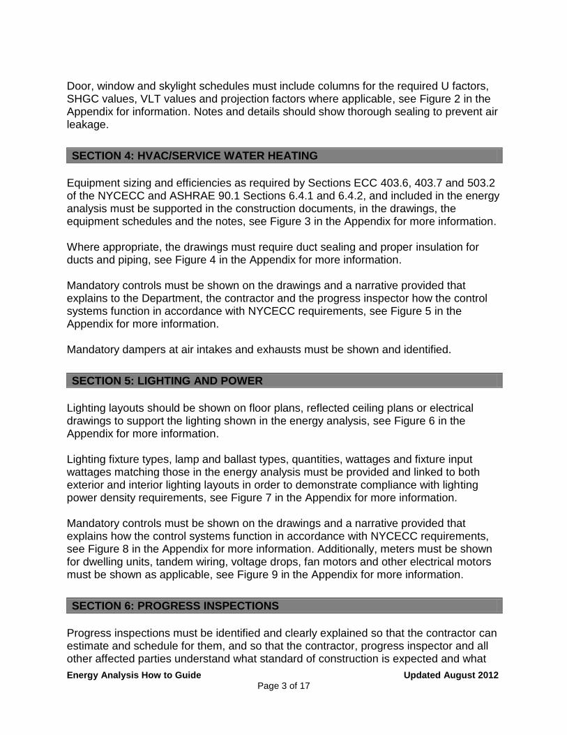
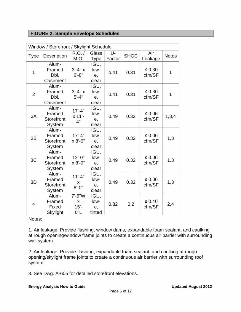
Door, window and skylight schedules must include columns for the required U factors, SHGC values, VLT values and projection factors where applicable, see Figure 2 in the Appendix for information. Notes and details should show thorough sealing to prevent air leakage.
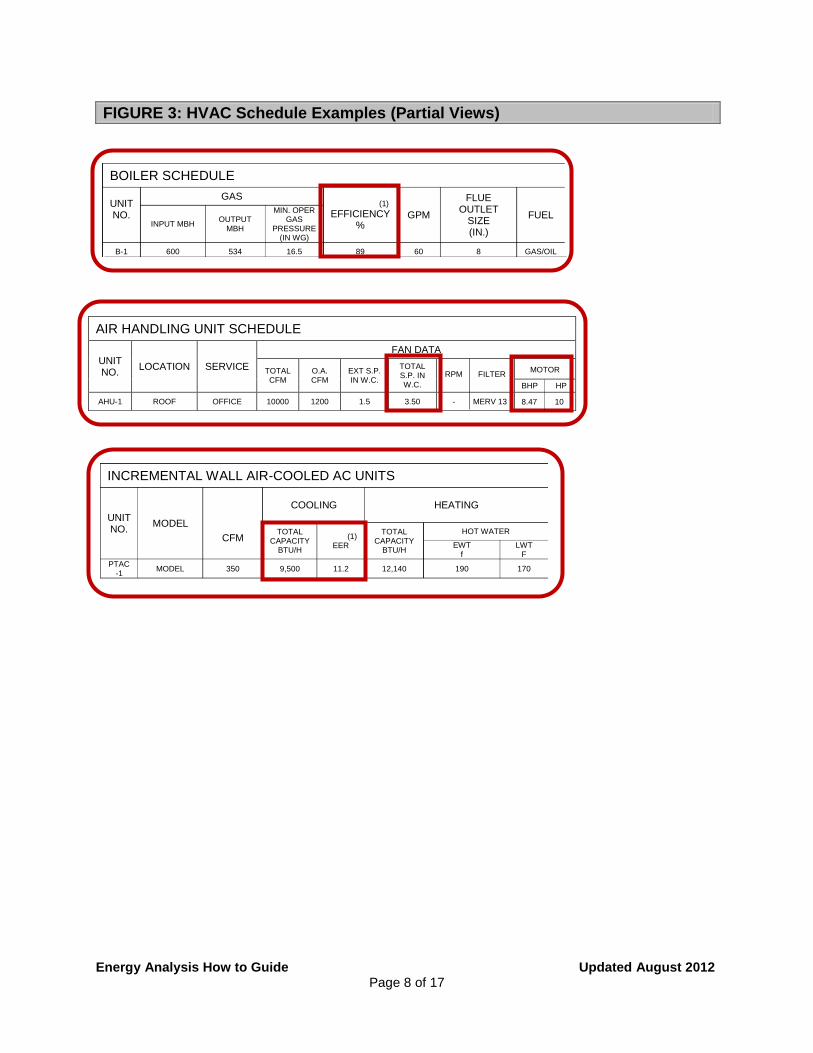
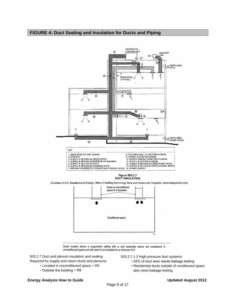
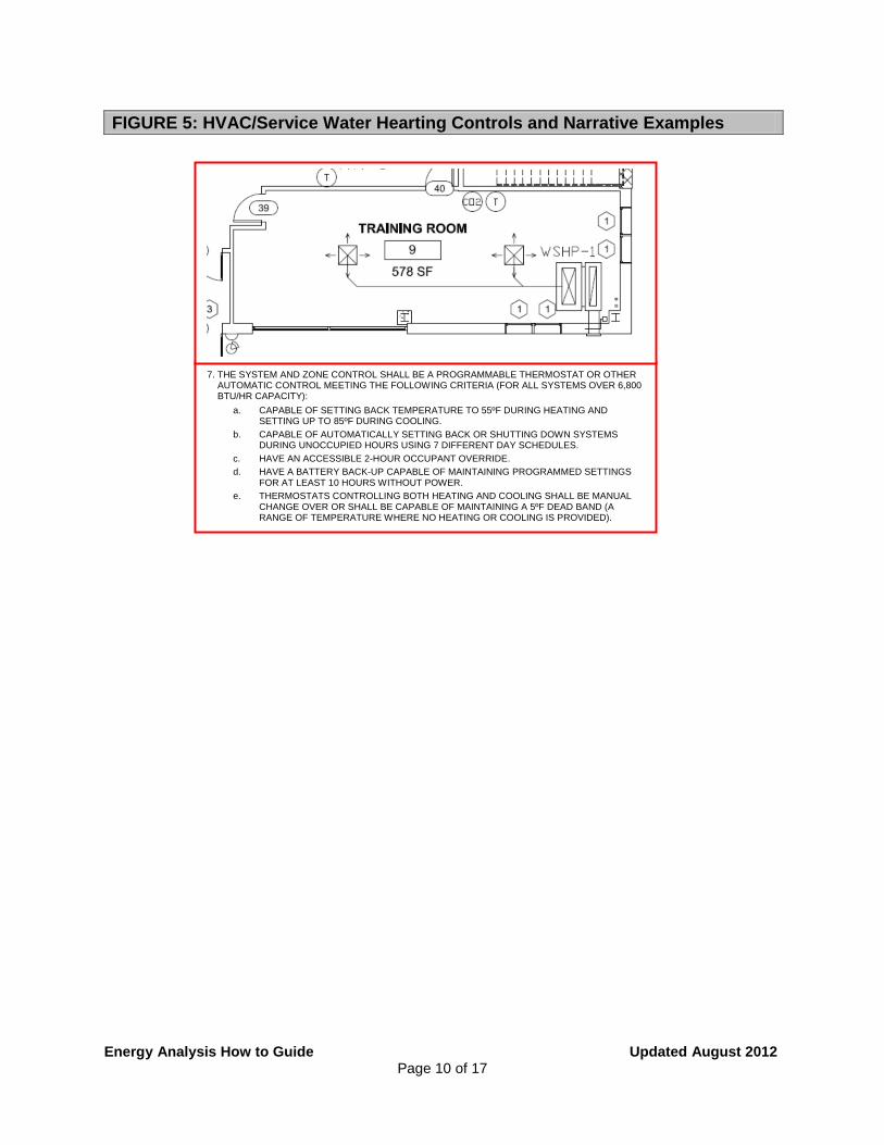
Equipment sizing and efficiencies as required by Sections ECC 403.6, 403.7 and 503.2 of the NYCECC and ASHRAE 90.1 Sections 6.4.1 and 6.4.2, and included in the energy analysis must be supported in the construction documents, in the drawings, the equipment schedules and the notes, see Figure 3 in the Appendix for more information. Where appropriate, the drawings must require duct sealing and proper insulation for ducts and piping, see Figure 4 in the Appendix for more information. Mandatory controls must be shown on the drawings and a narrative provided that explains to the Department, the contractor and the progress inspector how the control systems function in accordance with NYCECC requirements, see Figure 5 in the Appendix for more information. Mandatory dampers at air intakes and exhausts must be shown and identified.
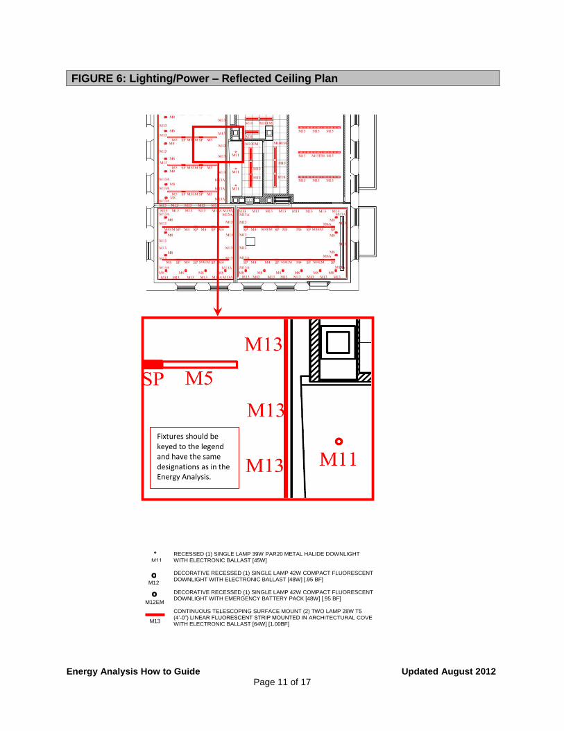
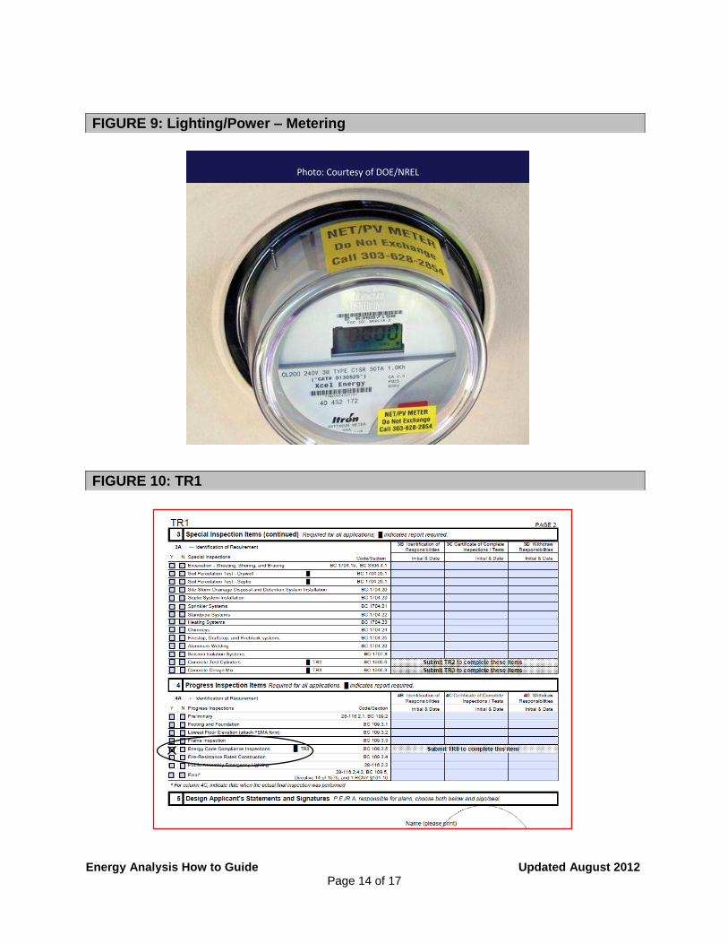
Lighting layouts should be shown on floor plans, reflected ceiling plans or electrical drawings to support the lighting shown in the energy analysis, see Figure 6 in the Appendix for more information. Lighting fixture types, lamp and ballast types, quantities, wattages and fixture input wattages matching those in the energy analysis must be provided and linked to both exterior and interior lighting layouts in order to demonstrate compliance with lighting power density requirements, see Figure 7 in the Appendix for more information. Mandatory controls must be shown on the drawings and a narrative provided that explains how the control systems function in accordance with NYCECC requirements, see Figure 8 in the Appendix for more information. Additionally, meters must be shown for dwelling units, tandem wiring, voltage drops, fan motors and other electrical motors must be shown as applicable, see Figure 9 in the Appendix for more information.
Progress inspections must be identified and clearly explained so that the contractor can estimate and schedule for them, and so that the contractor, progress inspector and all other affected parties understand what standard of construction is expected and what
SECTION 4: HVAC/SERVICE WATER HEATING
SECTION 5: LIGHTING AND POWER
SECTION 6: PROGRESS INSPECTIONS

Energy Analysis How to Guide Updated August 2012 Page 4 of 17
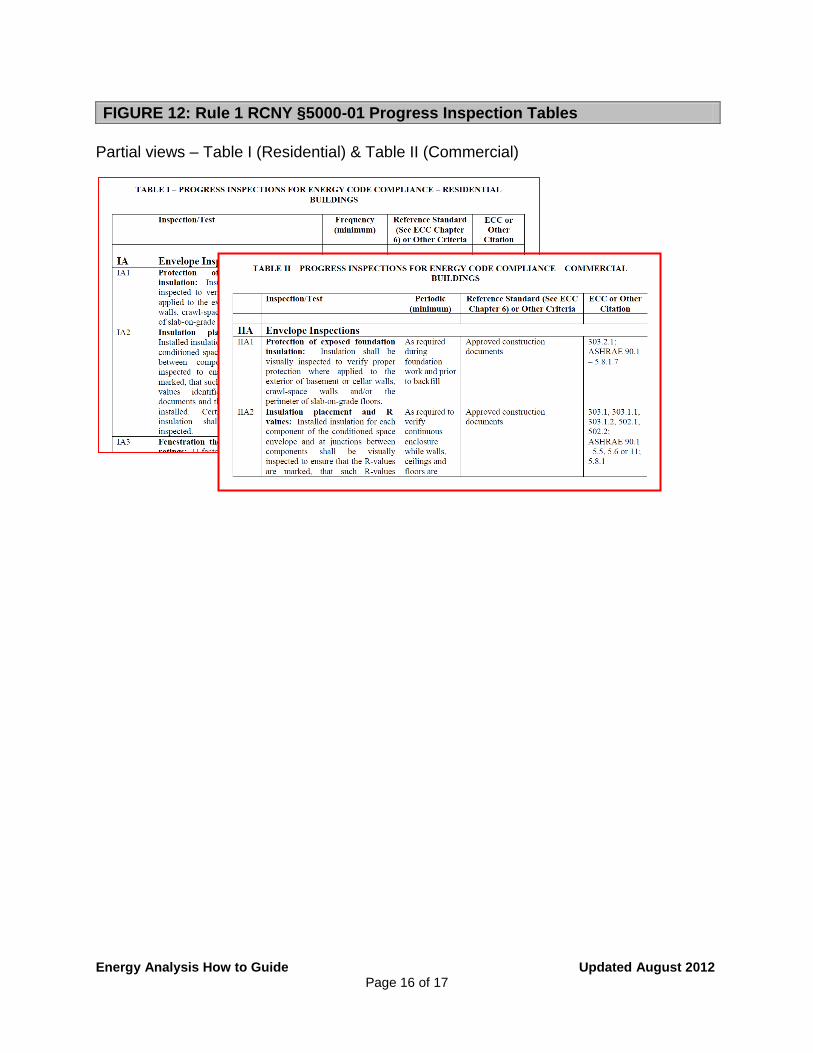
activities will be performed during construction. All information in Table I or II should be shown as applicable to the scope of work and accordingly the table may be replicated in the drawings and edited for the project work. Applications filed on or after September 7, 2010, are required to include the progress inspections on their drawings and check “Yes” for the progress inspection, “Energy Code Compliance Inspections,” on the filed TR1 form, see Figure 10 in the Appendix for more information. Applications filed on or after February 7, 2011, must be accompanied by a TR8 form – see Figure 11 in the Appendix for more information, 1 RCNY §5000-01 for more information on the progress inspection tables and Figure 12 in the Appendix for residential and commercial buildings. Also, see the Information About Forms page for more information as well.

Energy Analysis How to Guide Updated August 2012 Page 5 of 17
All Wall Assembly Types should be identified, corresponding to those noted in the Plans.
Insulation types should be identified and R-values stated throughout to match the Energy Analysis.
Wall sections and details should note materials and techniques to meet mandatory NYCECC Air Leakage requirements.
Wall Section Examples
SECTION 7: APPENDIX
FIGURE 1
Energy Analysis How to Guide Updated August 2012 Page 6 of 17
Notes: 1. Air leakage: Provide flashing, window dams, expandable foam sealant, and caulking at rough opening/window frame joints to create a continuous air barrier with surrounding wall system. 2. Air leakage: Provide flashing, expandable foam sealant, and caulking at rough opening/skylight frame joints to create a continuous air barrier with surrounding roof system. 3. See Dwg. A-605 for detailed storefront elevations.
FIGURE 2: Sample Envelope Schedules
Window / Storefront / Skylight Schedule
Type Description R.O. / M.O.
Glass Type
U-Factor
SHGC Air
Leakage Notes
1
Alum-Framed
Dbl. Casement
3'-4" x 6'-8"
IGU, low-e,
clear
o.41 0.31 ≤ 0.30 cfm/SF
1
2
Alum-Framed
Dbl. Casement
3'-4" x 5'-4"
IGU, low-e,
clear
0.41 0.31 ≤ 0.30 cfm/SF
1
3A
Alum-Framed
Storefront System
17'-4" x 11'-
4"
IGU, low-e,
clear
0.49 0.32 ≤ 0.06 cfm/SF
1,3,4
3B
Alum-Framed
Storefront System
17'-4" x 8'-0"
IGU, low-e,
clear
0.49 0.32 ≤ 0.06 cfm/SF
1,3
3C
Alum-Framed
Storefront System
12'-0" x 8'-0"
IGU, low-e,
clear
0.49 0.32 ≤ 0.06 cfm/SF
1,3
3D
Alum-Framed
Storefront System
11'-4" x
8'-0"
IGU, low-e,
clear
0.49 0.32 ≤ 0.06 cfm/SF
1,3
4
Alum-Framed Fixed
Skylight
7'-6"W x
15'-0"L
IGU, low-e,
tinted
0.82 0.2 ≤ 0.10 cfm/SF
2,4
Energy Analysis How to Guide Updated August 2012 Page 7 of 17
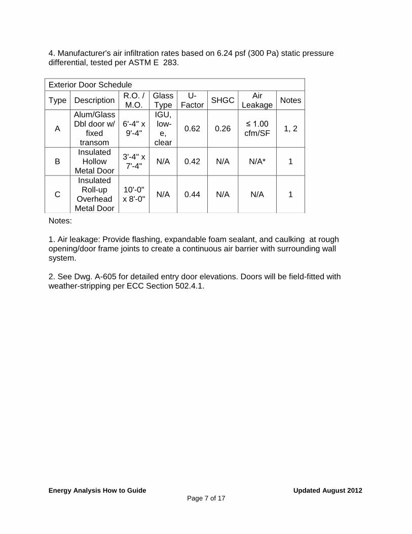
4. Manufacturer's air infiltration rates based on 6.24 psf (300 Pa) static pressure differential, tested per ASTM E 283.
Notes: 1. Air leakage: Provide flashing, expandable foam sealant, and caulking at rough opening/door frame joints to create a continuous air barrier with surrounding wall system. 2. See Dwg. A-605 for detailed entry door elevations. Doors will be field-fitted with weather-stripping per ECC Section 502.4.1.
Exterior Door Schedule
Type Description R.O. / M.O.
Glass Type
U-Factor
SHGC Air
Leakage Notes
A
Alum/Glass Dbl door w/
fixed transom
6'-4" x 9'-4"
IGU, low-
e, clear
0.62 0.26 ≤ 1.00 cfm/SF
1, 2
B Insulated Hollow
Metal Door
3'-4" x 7'-4"
N/A 0.42 N/A N/A* 1
C
Insulated Roll-up
Overhead Metal Door
10'-0" x 8'-0"
N/A 0.44 N/A N/A 1
Energy Analysis How to Guide Updated August 2012 Page 8 of 17
FIGURE 3: HVAC Schedule Examples (Partial Views)
AIR HANDLING UNIT SCHEDULE
UNIT NO.
LOCATION SERVICE
FAN DATA
TOTAL CFM
O.A. CFM
EXT S.P. IN W.C.
TOTAL S.P. IN W.C.
RPM FILTER
MOTOR
BHP HP
AHU-1 ROOF OFFICE 10000 1200 1.5 3.50 - MERV 13
8.47 10
BOILER SCHEDULE
UNIT NO.
GAS (1)
EFFICIENCY %
GPM
FLUE OUTLET
SIZE (IN.)
FUEL INPUT MBH
OUTPUT MBH
MIN. OPER GAS
PRESSURE (IN WG)
B-1 600 534 16.5 89 60 8 GAS/OIL
INCREMENTAL WALL AIR-COOLED AC UNITS
UNIT NO.
MODEL
CFM
COOLING
HEATING
TOTAL CAPACITY
BTU/H
(1) EER
TOTAL CAPACITY
BTU/H
HOT WATER
EWT f
LWT F
PTAC -1
MODEL 350 9,500 11.2 12,140 190 170
Energy Analysis How to Guide Updated August 2012 Page 9 of 17
FIGURE 4: Duct Sealing and Insulation for Ducts and Piping
503.2.7.1.3 High-pressure duct systems
• 25% of duct area needs leakage testing
• Residential ducts outside of conditioned space
also need leakage testing.
503.2.7 Duct and plenum insulation and sealing
Required for supply and return ducts and plenums
• Located in unconditioned space = R5
• Outside the building = R8
Energy Analysis How to Guide Updated August 2012 Page 10 of 17
FIGURE 5: HVAC/Service Water Hearting Controls and Narrative Examples
7. THE SYSTEM AND ZONE CONTROL SHALL BE A PROGRAMMABLE THERMOSTAT OR OTHER AUTOMATIC CONTROL MEETING THE FOLLOWING CRITERIA (FOR ALL SYSTEMS OVER 6,800 BTU/HR CAPACITY):
a. CAPABLE OF SETTING BACK TEMPERATURE TO 55ºF DURING HEATING AND SETTING UP TO 85ºF DURING COOLING.
b. CAPABLE OF AUTOMATICALLY SETTING BACK OR SHUTTING DOWN SYSTEMS DURING UNOCCUPIED HOURS USING 7 DIFFERENT DAY SCHEDULES.
c. HAVE AN ACCESSIBLE 2-HOUR OCCUPANT OVERRIDE.
d. HAVE A BATTERY BACK-UP CAPABLE OF MAINTAINING PROGRAMMED SETTINGS FOR AT LEAST 10 HOURS WITHOUT POWER.
e. THERMOSTATS CONTROLLING BOTH HEATING AND COOLING SHALL BE MANUAL CHANGE OVER OR SHALL BE CAPABLE OF MAINTAINING A 5ºF DEAD BAND (A RANGE OF TEMPERATURE WHERE NO HEATING OR COOLING IS PROVIDED).
Energy Analysis How to Guide Updated August 2012 Page 11 of 17
FIGURE 6: Lighting/Power – Reflected Ceiling Plan
Fixtures should be keyed to the legend and have the same designations as in the Energy Analysis.
O
M12
O
M12EM
O
M11
M13
RECESSED (1) SINGLE LAMP 39W PAR20 METAL HALIDE DOWNLIGHT WITH ELECTRONIC BALLAST [45W] DECORATIVE RECESSED (1) SINGLE LAMP 42W COMPACT FLUORESCENT DOWNLIGHT WITH ELECTRONIC BALLAST [48W] [.95 BF] DECORATIVE RECESSED (1) SINGLE LAMP 42W COMPACT FLUORESCENT DOWNLIGHT WITH EMERGENCY BATTERY PACK [48W] [.95 BF] CONTINUOUS TELESCOPING SURFACE MOUNT (2) TWO LAMP 28W T5 (4’-0”) LINEAR FLUORESCENT STRIP MOUNTED IN ARCHITECTURAL COVE WITH ELECTRONIC BALLAST [64W] [1.00BF]

Energy Analysis How to Guide Updated August 2012 Page 12 of 17
Fixture types, lamp and ballast types, quantities and wattages and fixture input wattages on drawings and schedules must match those in the Energy Analysis.
FIGURE 7: Lighting/Power – Schedule
TYPE DESCRIPTION PHOTOMETRY SYSTEM WATTS
VOLT CONTROL
INTENT MANUFACTURER
H1
Description:
Lamp: Optics:
Location/Remarks:
Ballast:
Pole:
ARM-MOUNTED COSMO OR LED NYCDOT LIGHPOLE 25’-0” A.F.G. WITH DAVIT ARM AND OCTAGONAL POLE.
(1) CPO-TW 140W/728 [2800ºK] [14.020 LUMENS] [PHILIPS] LUMINAIRE SHALL CONSIST OF A THERMAL RESISTANT FLAT GLASS LENS. LENS SHALL BE
HOUSED IN A CAST ALUMINUM ALLOW BODY. OPTICAL ASSEMBLY TO BE AN ANODIZED FULL-CUTOFF ASYMMETRIC TYPE III DISTRIBUTION REFLECTOR.
[ROADWAYS] LUMINAIRE HOUSING SHALL BE COMPRISED OF A DOOR FRAME AND CANOPY WHICH HOUSES INTEGRAL CONTROL GEAR. THE DOOR SHALL BE SECURED BY A CORROSION RESISTANT ALIMINUM LATCH PROVIDING TOOL-LESS ACCESS FOR
MAINTENANCE. THE CANOPY AND DOOR SHALL BE SEALED BY A SILICONE GASKET. FIXTURE SHALL HAVE UNIVERSAL MOUNTING SYSTEM TO BE SECURED ON A 1.88’ TO 2.38’ O.D. X MINIMUM 8’ LONG HORIZONTAL ARM. TOTAL LUMINAIRE EFFICIENCY SHALL BE
MINUMUM 75%. ENTIRE ASSEMBLY SHALL BE UL LISTED. SUITABLE FOR WET LOCATION. ICW140TLS [PHILIPS] [BALLAST TEMPERATURE RANGE -20ºC / +50ºC] BALLAST SHALL BE
ASSEMBLED ON A UNITIZED REMOVABLE TRAY WITH QUICK DISCONNECT PLUG. POLE SHALL BE NYCDOT STANDARD ALUMIINUM DAVIT (8’-0” ARM) SET IN NYCDOT
STANDARD OCATOGONAL STEEL POLE (TRANSITION AT NOMINAL 19’-0” AFG); TOTAL HEIGHT NOMINAL 25’-0” A AFG. POLE TO ACCOMMODATE STANDARD NYCDOT BOLT CIRCLE. POLE SHALL BE CAPABLE OF WITHSTANDING 100MPH WINDS WITH 1.3 GUST
FACTOR. PROVIDE WITH WEATHER-RESISTANT GFCI RECEPTACLE AT 14’-0” AFG.
185 watts 120 V
PHOTOCELL ON/TIMELOCK OFF
PHOTOCELL TO BE LOCATED ON EACH INDIVIDUAL
FIXTURE AS PER DOT SPEC.
LUMINAIRE: HOLOPHANE #15DHP-12-F-F-AS-R
POLE : NYCDOT WEST HOUSTON
BASE : OCT/FLATBUSH AVE
TRANSFORMER TYPE
OR APPROVED EQUAL BY TBD.

Energy Analysis How to Guide Updated August 2012 Page 13 of 17
Narrative example:
FIGURE 8: Lighting/Power – Controls and Narratives
Energy Analysis How to Guide Updated August 2012 Page 14 of 17
FIGURE 9: Lighting/Power – Metering
FIGURE 10: TR1
Photo: Courtesy of DOE/NREL

Energy Analysis How to Guide Updated August 2012 Page 15 of 17
FIGURE 11: TR8
Energy Analysis How to Guide Updated August 2012 Page 16 of 17
Partial views – Table I (Residential) & Table II (Commercial)
FIGURE 12: Rule 1 RCNY §5000-01 Progress Inspection Tables


