14
EDA Rig 3 Equipment List Page 1 of 14 ENERGY DRILLING AUSTRALIA Rig 3 Schramm TXD 200 (Sn. J135-0233)
EDA Rig 3 Equipment List Page 1 of 14
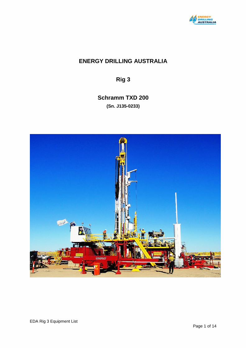
ENERGY DRILLING AUSTRALIA
Rig 3
Schramm TXD 200
(Sn. J135-0233)
EDA Rig 3 Equipment List Page 2 of 14
ENERGY DRILLING AUSTRALIA – Rig 3
Schramm TXD 200
EQUIPMENT AND INVENTORY
Component Description
Drilling Rig
The Schramm TXD Rotadrill is a heavy hoist, deep hole, trailer mounted top head drive drill rig with an automated pipe handling system.
The TXD utilizes innovative Schramm Telemast technology to achieve range
2 drill pipe/range 3 casing length capability in an efficient, readily transportable package and ideally suited for a range of applications.
The Schramm Rotadrill TXD Rig rated for 200,000 lbs nominal pullback.
Mounted on tri-axle gooseneck trailer with:
• Dual 5” bore x 36” stroke front jacks mounted on trailer frame.
• Dual 5” bore x 41” stroke rear jacks integral to the drilling rig main frame.
• 2” SAE removable king pin
• Two x 415 litre fuel tanks
• Deck mounted rig engine & radiator. Radiator rated for 54.5 degrees C ambient temperature.
Substructure Sub-base under rig carrier trailer. Height of sub-base 400mm clearance between rig floor and ground is 4200mm
TRAILER MUST BE SECURED TO SUB-BASE FOR PULLBACK OPERATIONS. Front of carrier is anchored to sub-base by two 6 tonne chain blocks. Top of bottom section of the mast is anchored to front of rig carrier trailer by two guy wires each with a 6 tonne chain block.
Approx. 8’ long x 14’ wide rig floor, with non skid working surface is an integral part of the pipe handling trailer and pins to the rear of rig, providing a level surface for rig crew approximately 12 ft (3.66 m) above ground level.
Pipe handling trailer sits on timber matting to stabilise the pipe handling unit. All landing legs are independently ballasted on large feet.
Rig trailer & rig floor elements include walkways, stairways and handrails to AS 1657 for access and egress.
Hydraulic Pull Back / Pull Down System
Hydraulic powered pull down and pull back.
Traverse in either direction achieved by hydraulic cylinders in compression telescoping the sliding mast, in or out
2 x 1-1/2” OD diameter traverse wire ropes over 2 x 27” PD Nylatron sheaves with a ratio wheel to rope of 18:1.
Installed rope type is 8 x 26 Rope, nominal breaking strength of 128.2 tons for each rope.
Nominal maximum pullback force: 200,000 lbs (90,909kg)
Actual Maximum Pull back force under TDS: 200,000 lbs
Nominal maximum pull down force: 32,000 lbs (14,545 kg)
Actual Maximum Pull down force under TDS: 32,000 lbs
Pull down speed: 200 fpm
Pull back Speed: 0 – 130,000 lbs @ 100 fpm
131,000 – 180,000 lbs @ 75 fpm

EDA Rig 3 Equipment List Page 3 of 14
Component Description
181,000 – 200,000 lbs @ 25 fpm
Rig Engine Detroit Diesel DDC/MTU 12V-2000TA DDEC, 760 bhp (567kW) @ 1800 rpm.
Engine is fitted with remote and local ESD, air start, spark arrestor muffler, rig air strangler shutdown & lagged exhaust.
Brushless 24 volt DC alternator fitted on the engine.
Rig Engine Electrical System
Power supply for use in explosion proof environment, consisting of (2) 12V gel batteries, power converter, charging circuit & LED operation indicator lights all installed in NEMA 4X enclosure. The power supply requires auxiliary power source; 6A @ 120VAC minimum (Multi voltage up to 240V, 50-60 Hz).
Hydraulics System Ten (10) hydraulic pumps including three (3) fixed displacement type and seven (7) variable volume piston type pumps to provide hydraulic power for all rig functions.
All hydraulic circuits are fully filtered, protected by relief valves and include an oil cooler. Different hydraulic circuits have different hydraulic working pressures. Maximum hydraulic system pressure is 4,800 psi.
Rotation Torque limiter – control panel mounted valve to regulate hydraulic pressure to the rotation motors.
Hydraulics Supply to Remote units.
Separate hydraulic pump and controls plumbed to outlet ports with twin quick connect fittings are mounted to provide hydraulic oil supply for remote auxiliary equipment. Control is provided through an operator’s panel mounted valve.
Maximum oil flow: 58 gpm
Maximum pressure: 5000 psi
Horsepower requirement: 175 hp approx.
Mast
Schramm Telemast with 50’ (15.24m) Top Head travel.
Telescoping construction permits long head travel and working height, yet short overall length in the transport position. The mast scopes out raising and lowering the TDS on traverse cables anchored at deck level, which connect to the top of the TDS via crown sheaves on the top of the moving mast inner section.
Mast Hoist Capacity: 200,000 lbs (90,909 kg)
Pull down Capacity: 32,000 lbs (14,545 kg) @ 200 fpm.
2 x 3 stage hydraulic mast raise cylinder with burst protection (velocity fuse) on each cylinder.
Mast is locked in vertical position by two wedges below the rig floor.
Mast is free-standing and equipped with two 72” (1829 mm) stroke cylinder slides, all mast loads are transferred direct to the ground not back through the rig frame.
Floor height currently set at 3.8m above ground level.
Clearance from underside to Ground Level is 3.4m.
Working clearance mast:
52’ 10” (16.1 m) spindle to table (floating sub removed)
48’ 10” (14.9 m) floating sub to table
The mast base has a 20” (508 mm) diameter opening with all slips removed and is hydraulically retractable, with a 30 ¼” (768 mm) opening when fully retracted.
Centreline of the borehole is 44 ½” back from the rear plate of the rig.
EDA Rig 3 Equipment List Page 4 of 14
Component Description
Crown Block Two sets of two 27” PD Nylatron traverse line sheaves
Mast Lubrication System
Multipoint system to simplify lubrication of drill components. Provides centralized grease fitting locations for top head, crown and jib boom.
Top Head Drive Assembly
4 motor tilting (pivoting) unit.
A heavy duty single reduction (3.5:1) top head design.
The top head hydraulically tilts to facilitate pipe and casing handling.
Includes hydraulic lock pins to retain top head in the drilling (vertical) position.
The THD is equipped with bail eyes rated at 200,000 lbs.
Top Drive Spindle through hole: 4.75” ID (120.6 mm)
Output thread: 5 ½”API IF box.
Swivel: King Capsule Type, 3,000 psi, 3" ID
Four (4), two speed high torque, hydraulic motors:
• Low Gear 0 - 90 rpm @ 17,500 ft-lbs,
• High Gear 0 – 180 rpm @ 7,670 ft-lbs.
An auxiliary rotation circuit is provided to allow slow rotation while utilizing the rapid feed circuit. Clockwise rotation only up to 25 rpm.
Rotation horsepower: 367 hp (275 kw)
Top Head travel: 50’ (15.24 m)
TDS Hoist Capacity: 200,000 lbs (90,909 kg)
TSD Pull down Capacity: 32,000 lbs (14,545 kg) @ 200 fpm
Manual upper kelly cock fitted for drilling operations.
Floating Sub High capacity floating sub to remove feed cylinder and pipe weight forces from threads while making and breaking tool joints.
Spline construction permits free float of 4” (102 mm), has 3 ½” (89 mm) through bore (water course). Floating sub is 5 ½” IF pin up x NC46 PXB box down and fitted with short double pin NC46 PXB saver sub.
Sub incorporates a rotation lock – A disc brake locking mechanism preventing the top head gearbox from rotating during down hole directional drilling operations
Automated pipe handling system
Comprises tubular handling system, drill pipe storage racks and work platforms on a custom built tandem axle trailer equipped with ABS brakes, DOT lights and 2” SAE king pin. Trailer transport width is 9’ 2”.
The trailer unit hooks to the mast area to maintain proper alignment and has two swing outside rack arms per side, each equipped with a hydraulic outrigger cylinder to level the arm. Approximately 19 x 4 ½” OD upset R2 drill pipes can be staged in one layer, per side.
Drill pipe and casing are rolled into and off the pipe handling lift cradle from the side rack arms using the outrigger hydraulic legs to raise or lower the outboard end of the arms..
Drill pipe and casing handling system lifts forward end of tubulars from horizontal position to align with tilting top head and advances forward or slides back to allow clamping of the tubular in the clamp jaws and attachment to the top head.
Built in clamping system on pipe handler allows for make-up or break-out of tool joints from top head spindle. Clamp can pass 30” casing with jaws removed.
Clamping jaw sets available for 2⅜”, 2⅞”, 3 ½”, 4, 4½”, 4 ¾”, 5”, 5¼”, 5½”, 6¼”, 6½”, 6⅝”, 7⅝”, 8⅝” and 9⅝” OD tubulars.
EDA Rig 3 Equipment List Page 5 of 14
Component Description
The main controls for the pipe handler are located on the rig floor.
Additional pipe handler control station is located at ground level under the rig floor.
Capable of handling tubular length up to 47’ (14.3 m)
Capable of handling tubular weight up to 2273 kg.
Cradle slide travel (forward & back): 8 ft (2.4 m)
Loading rack / Arm Height: approximately 1.6m above ground level.
Jib Boom Jib boom located on the top RHS of the outer mast, with a worm gear drive to swing the boom side to side and a hydraulic cylinder to extend and retract the boom. Boom has 140 degree swing and 40” (1.016 mm) retract and extend.
Boom winch line is weaved through a snatch block to increase load line flexibility. This permits the winch line to be centred over the borehole and reduces sheave wear when pulling from unusual angles.
Jib Boom Capacity: 12,000 lb (5455 kg) retracted, 5000 lb (2268 kg) extended.
Winch for Jib Boom Braden PD12C hydraulically powered winch mounted to the back of the mast. The winch is a planetary type with overrunning clutch, hydraulic brake valve and spring applied hydraulic release brake. The winch operates independently of the other drilling functions.
Drum capacity: 547 ft (167 m ) of ½” cable (12.7 mm)
Bare drum: 9,600 lb (4354 kg), 151 fpm (46 mpm)
150 ft drum: 8,700 lb (3,946 kg), 165 ftpm (50.3 mpm)
Cable fitted: 150 ft (46 m) of ½” (12.7 mm) HSLR (high strength low rotation) cable.
Survey Line Jib Boom
Slews over hole centre for running surveys and slews away for normal drilling operations. Jib Boom Capacity: 3,000 lb (1,361 kg) retracted, 1000 lb (454 kg) extended.
Survey Line Winch Hydraulic powered auxiliary winch mounted on off driller side of bottom mast section. Drum capacity for 6000 ft of 0.092” survey line.
Survey line runs over sheave hung from survey line jib boom.
Power Make Up / Break Out Unit.
Arm mounted Schramm hydraulic power make up /break out unit operated from the driller’s console.
Arm mounts on the RHS of the mast and swings beneath the top head by a hydraulically powered geared actuator. The lower jaws are clamp only while the upper jaws rotate to make or break the connection. No pipe spinner capability.
The unit has 40” of vertical travel for height adjustment.
Jaw dies to cover the range 2-3/8 ” to 9-5/8” diameter.
Clamping force: adjustable to 73,000 lbs
Break/Make torque: 53,000 ft/lbs.
Fitted with Audible Alarm when moving and a dead man switch to operate by the AD
Blow Out Preventers One (1) 11” 3000# W.P. Integrated Spherical Style Annular BOP
Bore: 11”
Working Pressure: 3000 PSI
Top Connection: 11” 3000 studded with R53 ring groove
EDA Rig 3 Equipment List Page 6 of 14
Component Description
Bottom Connection: 11” 3000 flanged with R53 ring groove
Packing Element: Nitrile Rubber
Height: 33 ½”
Weight: 6,000 Lbs.
Closing Volume: 11.00 US Gal. (41.58 L.)
Opening Volume: 6.78 US Gal. (25.63 L.)
Certification: API 16A, NACE MR01-75, Latest Edition, ERCB 3 Year Inspection
One (1) 11” 3000# W.P Integrated (IWS) Hydraulic Double Ram BOP
Bore: 11”
Working Pressure: 3000 PSI
Top Connection: 11” 3000 studded with R53 ring groove
Bottom Connection: 11” 3000 studded with R53 ring groove
Outlets: None
Ram Blocks: One set CSO (Blind) T70, One set
Pipe Rams T70 each with Holders.
Height: 29 ½”
Weight: 4,350 Lbs.
Closing Volume: 1.74 US Gal. (6.58 L.) per ram.
Opening Volume: 1.45 US Gal. (5.48 L.) per ram.
Certification: API 16A, NACE MR01-75 Latest Edition,
ERCB 3 Year Inspection
All BOP hydraulic hoses are Co-flexip type, fireproof.
BOP storage & transport system
Steel transport & storage frame including test stump. Handled by forklift.
BOP Test Stump 1 x 11” test stump incorporate as BOP storage and travel rack.
BOP Accumulator R & T Controls Model 80GU, 6 functions (only 4 in use), 80 Gallon BOP Accumulator Control Unit.
Unit is manufactured to meet ISO 9001, API 16D.
Consists of twelve 11 gallon, 3,000 Psi working pressure separator bladder type accumulators which are provided with ASME U-1A certificates. System is designed to operate in ambient temperature Classification be -10°C/+40°C
Unit has one (1) pressure relief valve set at 3,300 Psi. The pressure relief valve prevents over pressuring the accumulators and pump systems, and is self-resetting. Relief valves comply with API RP 16E. Paragraphs 2 3 2 and 5 3.
One (1) electric pump module model number UET10-B using triplex pump series, T-10 and equipped with 1” plungers. The triplex reciprocating plunger pump is a heavy-duty pump capable of operation even when small pieces of debris get into the system. Pump is unitized with one new 15 Hp explosion proof IEC Ex electric motor.
In addition it has one (1) 8½” air driven motor coupled to 40:1 ratio plunger pump with self-adjusting packing. This assembly produces approximately 5 GPM at mid-range pressure of 2,000 psi.
BOP Remote Control Panel
One (1) air pilot operated graphic remote panel for remote display of unit pressures as well as functioning of both ram functions, and by pass regulator. This is mounted inside doghouse with umbilical connection to
EDA Rig 3 Equipment List Page 7 of 14
Component Description
koomey and is fitted with annular pressure regulator, annular pressure gauge, accumulator pressure gauge, rig air pressure gauge & bypass control valve
System incorporates pneumatic alarm system designed to alert driller of problems with the control unit. Visual indication is displayed by pneumatic indicators showing green if everything is ok and red when there is a fault. When a fault occurs, horn sounds. An isolation valve is provided to disable to horn if fault isn't immediately repairable. Alarms are:
• Low Tank Level
• Low Accumulator Pressure
• Low Supply Air supply
Choke Line Valves 1 x 3⅛” 5000 psi remotely (hydraulic) operated valve
1 x 3⅛” 5000 psi manual valve
Kill Line Valves 1 x 2-1/16” 5000 psi valve
1 x 2-1/16” 5000 psi check valve
Choke Line 3” 5000 psi coflex type choke hose with 3” bore. Fitted with 3⅛” x 5000 psi flanges. 6m long hose.
Kill Line 2-1/16” 5000 psi flanged to 2” kill hose with 2” bore, 8m long.
Choke Manifold 3⅛” x 5,000 psi 4 way block located on dedicated skid housing both the choke manifold and poor boy degasser.
3⅛” 5000 psi inlet choke manifold, with single 3⅛” 5000 psi bypass valve
2-1/16” 5000 psi choke chambers leading to one adjustable manual chokes and one remote (hydraulic); each choke has a 2-1/16” 5000 psi downstream isolating valve; at the back of the manifold each line enters a 4 way block and the blocks are connected to each other by 2-1/16” 5000 psi valves. Each block has an external isolating valve down to hammer union.
Test inlet is via 5 way block with a riser consisting of 3⅛” 5000 psi valve with 3 way data header for pressure point.
Flareline 3” schedule 40 pipe with figure 200 hammer unions. 45m length and anchors.
Auto Igniter Gas fuelled auto igniter unit provided.
Mud Gas Separator Poor boy type Degasser is manufactured by DFE New Zealand and consists of;
1 x Vertical 36” x 20’ elevated mud gas separator with;
4” inlet on degasser
2” hose from choke manifold
8” mud discharge to shaker
6” vent line
Design temp; 0-100
Operating temp; 0-80
Design Pressure; 150psi
Operating Pressure; 100psi
Hydrotest (max test pressure); 230psi
Fluid density design 2.3
4’ Butterfly dump valve on bottom of unit
24’ inspection hatch
12.5 ft mud seal.
EDA Rig 3 Equipment List Page 8 of 14
Component Description
Mud Gas Separator Vent Line
6” schedule 160. 2.5m pipe vent to atmosphere.
Drilling Spool Adaptor
1 x 11” 3k 600mm DSA mounted below Mud-Cross
Riser & Flow Lines 10” round enclosed riser flow-line to 9” mud return to shale shaker
1 x 14” surface hole riser
Drillers Cabin 1 x hydraulic elevated doghouse rising from within a 500bbl day water tank with full instrumentation and air conditioning. Telescopes down into day water tank for transportation. .
Doghouse incorporates:
Drillers console
BOP remote control panel
Remote mud pump controls
Centralised emergency stop control
Pipe handler controls
Engine monitor instrumentation
Drillers control panel
AIRDRILL designed and manufactured control panel is located in doghouse with the following features and specifications:
• Type: 24 Volt DC electric over hydraulic with Parker IQAN electronic control system. Zone rated.
• Panel includes all necessary instrumentation and controls for drilling functions.
• Water pump control
• Emergency stop controls
• Power Supply: 24V DC supplied by deck engine.
Pipe handler controls located in doghouse. Pipe handler rig up controls are located on handler trailer
Engine control panel and rig-up functions are located on the rig deck accessible from ground level.
Auto drilling system Rig fitted with slow feed control only.
Mud Pump Two (2) Gardener Denver PZ-8 triplex mud pump mounted on oilfield skid base.
Max pressure 5,000 psi
Driven by 805hp Detroit Diesel, MTU 12V – 2000
Allison Transmission Model DP8962 with electric shift control
Electric driven low rpm lube pump
Residential type Spark arresting muffler with all exhaust piping covered with heat blankets.
10” X 6” Suction manifold w/screens
4” discharge manifold, Type Solid Block
3” pressure safety valve
0-6,000 psi pressure gauge
4” 5000 psi rated 20 Gal discharge pulsation damper and strainer cross with applicable flanges for discharge connections
Maximum continuous RPM 145 (Jack Shaft-652/Min)
Pump is supplied with 6½” liners and pistons. Other sizes can be made available upon request subject to availability.
EDA Rig 3 Equipment List Page 9 of 14
Component Description
Max pressure with 4” Liners 5,000 psi (189 GPM@ 145 strokes)
Max flow with 7” Liners 1,996 psi (580 GPM @ 145 strokes)
Controls for mud pump engine throttle, gears and stop valves located at the drillers control panel in the doghouse.
Pump fitted with emergency stop controls, stroke counters, air strangler, and fire suppression system.
Pump engine is electric start.
Charge Pump for Mud Pump
Charge pump is an electrically driven SPD 6 x 5 x 14 pump with 5” discharge, 6” suction, 14” impellor. Electric motor is a 50hp 1800rpm motor @ 50 Hz.
High Pressure Mud Lines
Air/mud fluid lines 3” schedule XXS. Mast plumbing is fully welded with no screw connections and is rated to 5,000 psi Includes a 5,000 psi mud gauge, mud pump knock-off connection union,
Standpipe manifold Stand Pipe: 3”, 5000 psi working pressure. Fitted with welded and/or integral fig 1502 union connections.
1 x 3” gate valve to isolate flow to mast stand pipe and 1 x 2” gate valve mounted below with T outlet to Kill Line. Manifold mounted on side of mast with direct access from drill floor
Standpipe Isolation Safety Valve
1 X 3000 psi hydraulically actuated ball type valve located at lowest point on rig standpipe manifold to shut in the standpipe. Valve controlled from drillers console
Mud Tank System Active capacity 460 bbl tank Mud System mounted on hydraulic rock-over trailer for easy/fast manoeuvrability.
1 x 20bbl sand trap, 1 x 80bbl settling tank, 2 x 130bbl equalising tank, 1 x 100 bbl pill tank. Total 5 compartments
All valves are operated from floor level using T-Handle tool
Mud pump suction via 8” suction from all equalising tanks and pill tank
Trip tank is located for easy viewing
Centrifugal pumps are Magnum 250 Series with mechanical seals. All electric motors are AusEx compliant.
Mud guns in all bays of the mud tank.
Mud mixing equipment
Three (3) Agitators are DFE HD Heavy Duty Axial Flow. The agitators are right angle low profile helical bevel type with 4 bladed axial flow impellors..
Solids Control Equipment
2 x Drilling Fluid Equipment (NZ) Model SCR-HG Linear Motion Shakers with the following features;
• G – Force: 4.0 – 7.3 G continuous (AWD)
• Screen Area: 28.1 ft²
• Deck angle Adjustment: Adjustable from -1° downhill to +5° adjustable whilst in operation
• Screen Panels: 3 panels per deck. Screen are made and labelled in accordance with API recommended guidelines 13C and E.
Day Water Tank 1 x Hydraulic rock-over trailer for easy/fast manoeuvrability with 500bbl water tank with hydraulic elevated doghouse, transfer pump, high pressure wash pump and fire hydrant.
Generators Rig (main) Generator - One (1) Rig generator located in combination building with the following specifications;
• Model Number: GEH275-SAE
EDA Rig 3 Equipment List Page 10 of 14
Component Description
• Rating: Prime rated @ 250kVA, 200kW, 3-phase, 415v, 50Hz, 1500rpm
• Engine Model: GCB330A Perkins diesel engine, direct coupled to a brushless alternator
• Fuel Tank: 550 litre base mounted with float switch and fuel solenoid with self bunded engine bay.
• Canopy: Sound attenuated, lockable enclosure rated at 61.7 dBa@7m on full load
• Spill management tray
Compressor One (1) only Champion CSF30 Rotary screw air compressor rated at 174cfm @ 7.8bar. Air is reticulated via quick disconnect hoses and fittings to various building and engine modules for positive shutdown (strangler valves), operation of doghouse window wipers, air supply to koomey backup power pack and general use as required.
Two (2) x 520 litre air receiver tanks adjacent to Compressor with one tank dedicated as a backup to the koomey.
Bulk Fuel Storage One trailer mounted 24,500 litre capacity self bunded tank manufactured and complies with AS1692 & AS1940.
Tank is fully baffled for transport and has an emergency pressure vacuum vent with rollover shutoff protection.
Handrails and stairwells for access and egress comply to AS1657
Features of the units consist of;
• Loop feed system circulating diesel fuel to all engines with return to tank for cooling using AusEx rated electric motor and pump with a capacity of 5 litres per minute.
• Backup fuel circulating pump
• High flow fill pump using AusEx rated electric motor and pump with a capacity of 30 litres per minute.
• Anti-static hose reel.
• Earth stake
• Hi-flow fuel meter
• Fast fill capacity for transfer of fuel between commercial fuel tanker and tank
Oil & Lubricant Storage
One (1) 10’ bunded container mounted forward of the fuel trailer on gooseneck with bulk oil, packaged oil and filtration storage capability.
Dangerous Goods Storage
Storage cabinet for paints and aerosols in the Rig tool shack
Waste Oil Storage Dedicated 1000 litre self bunded tank located on the rear of the fuel trailer together with SULO bin for storage of old rags and filters.
Tool Shack / Fitters Store
Fitters store consists of 1 x 20’ container comprising of;
Bench, grinder/wire wheel, hydraulic hose crimp, vice, tools, storage cupboards and generator / welder.
Parts storage consists of 1 x 20' container with protected shelving
Both containers are located on a 48’ oil field skid for handling with a winch truck
Rig lighting Stahl 2 x 36w florescent EX rated (zone 1) light fittings are located in the following locations: 6 x rig mast, 2 x cellar, 2 x rig deck, 4 x mud tank deck including shaker, 2 x mixing pump room, 1 x choke manifold room, 1 x
EDA Rig 3 Equipment List Page 11 of 14
Component Description
stairwell on mud tank, 1 x stairwell of doghouse, 1 x inside doghouse, 1 x bulk fuel tank, 1 x koomey room, 1 x compressor room, 1 x storage room and 1 x main rig generator room, 1 x emergency generator room.
In addition for flood lighting we have installed several Cooper EX rated (zone 1) L.E.D lighting which feature 100V to 300V hence not affected by voltage fluctuations, instant lighting when switched on. All L.E.D lights are located as follows: 3 x top of doghouse pointing in various directions including up the mast, 2 x on the combination building pointing to strategic locations. Zone rated lighting compliant to API500-505. Two x back of pipe handler, 4 x mud tank pointing to strategic locations, 2 x fuel pointing to strategic locations.
All lights are protected via earth leakage and circuit breakers, PO’s have lockout (isolation) capability and all fitted with wire safety harnesses.
Rig Emergency Lighting
The lighting circuit is split into two circuits. Emergency lighting is provided by the Stahl 2 x 36 lights with internal battery backup.
Stahl hazardous areas 230V twin 4 ft fluorescent emergency light fittings
Mud tanks x 3
Mud pumps x 3
Main engine x1
Power control rooms / Compressor Skid x4
Sub structure x5
Driller Cabin x2
Accumulator x2
Drill Pipe 200 joints of 4½” OD 16.6# G-105 drill pipe with 4” IF (NC 46) connection Range 2 with IEU, tool joint OD 6⅜”, ID 3”, box tong 12” and pin tong 9”
Drill Pipe Pup Joint Two (2) 5’ pup, 4½” OD 16.6# G-105 drill pipe with 4” IF (NC 46)
Two (2) 10’ pup, 4½” OD 16.6# G-105 drill pipe with 4” IF (NC 46)
Two (2) 15’ pup, 4½” OD 16.6# G-105 drill pipe with 4” IF (NC 46)
All have 6” OD tool joints
Drill Collars 10 x 6¼” Range 2 spiral drill collars with 4” IF (NC46) connection, OD 6¼”, ID 2¼” with bore-back box and pin stress relief groove.
Heavy Weight Drill Pipe
10 x 4½” HWDP with NC46 Connection tool joint, OD6⅜” tool joint ID: 2⅞” box & pin tong 24”. Boreback box, stress relief groove pin
Tubular Storage 3 x trailer mounted pipe cradles for the storage and transport of drill pipe. Each cradle is equipped with 1 x sub baskets pin locked onto front of cradles
Crossover Subs 2 x DP to DC 6-1/2” OD 4” IF box x 4” IF pin cross-over
2 x DP to DP 6” OD 4” IF box x 3 1/2” IF pin cross-over
2 x DP to DP 6” OD 3 ½”” IF box x 4” IF pin cross-over
2 x DP to DP 6” OD 4” IF box x 3 1/2” REG pin cross-over
2 x DP to DP 6” OD 3 1/2” REG box x 4” IF pin cross-over
2 x DP to DP 6” OD 4” IF box x 4 1/2” IF pin cross-over
2 x DP to DP 6” OD 4 1/2” IF box x 4” IF pin cross-over
1 x DP to DP 6” OD 4 1/2” IF box x 3 1/2” IF pin cross-over
1 x DP to DP 6” OD 3 1/2” IF box x 4 1/2” IF pin cross-over
Lifting subs: Lifting subs to suit all rig subs
Saver Subs 2 x saver sub 6” OD 4” IF box x 4” pin (short)
EDA Rig 3 Equipment List Page 12 of 14
Component Description
Bit Subs 2 x 12 ¼” bit sub 6 ½” OD 4” IF Box x 6 5/8” REG
2 x 8 ½” bit sub 6 ½” OD 4” IF Box 4 ½” REG box
Bored for floats
Casing Running Subs
1 x 6” OD, NC46 box to 9-5/8” buttress pin cross-over.
1 x 6” OD, NC46 box to 7” buttress pin cross-over
1 x 6” OD, NC46 box to 5-1/2” buttress pin cross-over
1 x 6” OD, NC46 box to 2 3/8” EUE pin cross-over
1 x 6” OD, NC46 box to 2-7/8” EUE pin cross-over
1 x 6” OD, NC46 box to 3-1/2” EUE pin cross-over
Power Slips Cavins Model “F” spider with slips and inserts for 2-3/8”, 2-7/8”, 3 ½”, 4”, 4-1/2, 5”, 5-1/2”, 6”, 6-1/4”, 6-5/8”, 7-5/8” and 8-5/8” tubulars.
The unit has an air operated actuator, operated from the drillers console and is equipped with full circle (FCR) slips with replaceable FCI inserts.
The spider is bolted to a Cavins F adaptor bushing which installs directly into the table in the base of the mast. The bushing and spider are retained to resist rotation.
Load capacity: 200,000 lbs
Solid spider and adaptor bushing, slip bowl/slip box is a split unit.
Handling Tools for Casing & Tubing
Manual Slips for 9⅝” casing
Safety Clamps (dog collars) for 7” and 9⅝” casing
Cup Tester Cup tester sub (3-1/2” IF box up, pin down) with rubber for 7” casing.
Cup tester sub (4” IF box up, pin down) with rubber for 9⅝” casing.
Inside BOP 1 x NC46 x 6⅜” OD IBOP
Kelly Cock 1 x NC46 x 6⅜” OD Kelly Cock.
Stabbing Valve (Kelly Cock Type)
1 X NC46 stabbing valve
Drill string circulating heads
1 x 6-1/4” OD x 21/4” ID x 450mm long side entry sub with 3-1/2” IF pin down & 2” figure 1502 XXS integral side inlet connection.
1 x 6-1/4” OD x 21/4” ID x 450mm long side entry sub with 4” IF pin down & 2” figure 1502 XXS integral side inlet connection.
Wellhead Installation Tool
Potato masher type for 11” Bradenhead
Handling tools for tubing
2⅞” slip set for Cavin Type F manual spider
Power Make up / Break out Tong Dies for 2-7/8” tubulars
Pipe handler grabber dies for 2⅞” tubulars
Water & sump transfer pumps
One (1) 3 x 2 x 11 centrifugal pump fitted with a 7.5 Hp electric motor and 9" impeller water transfer pump permanently located on the end of the day tank / doghouse.
1 x Sump (turkeys nest) pump - 3’’ Electric Start Diesel Powered supply pump with 75 metres of lay flat hosing.
Gas Detector Systems
1x Hard wired Crowcon gas detection system as used throughout the industry.
It uses IECEX certified “Xgard” EXD detectors feeding information back to a controller in the doghouse.
It features X3 H2S sensors at the shakers, bell nipple and the cellar, and X3 LEL sensors at the bell nipple and the shakers.
EDA Rig 3 Equipment List Page 13 of 14
Component Description
When gas is detected a beacon and audible alarm is set off on the rig floor. The audible alarm has 2 tones (LO and HI level). A flashing beacon is also activated in the dog house when any gas is detected.
Fire Suppression System
One (1) x 65 Litre Rise Of Pressure Suppression System fitted to Schramm Drill Rig.
One (1) x 65 Litre Rise Of Pressure Suppression System fitted to Gardener Denver PZ-8 pump skid.
One (1) x 45 Litre Rise OF Pressure Suppression System fitted to main rig generator
Alarm system Visual and audible alarms incorporated on doghouse.
Rig Motor Remote Emergency Shutdown System
All engines on site have the ability to be shutdown individually through use of the independent stop devices fitted at various and easy to reach locations on each piece of equipment.
In addition both mud pumps and the rig HPU engine can be emergency stopped individually from the doghouse. There is also an overall E stop system that shut downs all rig engines if tan Estop is actuated in the doghouse, or outside the Rig Managers office. Emergency stopping activates air shutoff solenoid valves on all engines
E&OE
EDA Rig 3 Equipment List Page 14 of 14


