1536-1276 (c) 2015 IEEE. Personal use is permitted, but republication/redistribution requires IEEE permission. See http://www.ieee.org/publications_standards/publications/rights/index.html for more information. This article has been accepted for publication in a future issue of this journal, but has not been fully edited. Content may change prior to final publication. Citation information: DOI 10.1109/TWC.2016.2517626, IEEE Transactions on Wireless Communications 1 Energy-Efficient 5G Outdoor-to-Indoor Communication: SUDAS Over Licensed and Unlicensed Spectrum Derrick Wing Kwan Ng Member, IEEE, Marco Breiling Member, IEEE, Christian Rohde, Frank Burkhardt, and Robert Schober Fellow, IEEE Abstract—In this paper, we study the design of the user selection, the time allocation to uplink and downlink, and the transceiver processing matrix for uplink and downlink multicarrier transmission employing a shared user equipment (UE)-side distributed antenna system (SUDAS). The proposed SUDAS simultaneously utilizes licensed frequency bands and unlicensed frequency bands with large available bandwidths (e.g. the millimeter wave bands) to enable a spatial multiplexing gain for single-antenna UEs to improve the energy efficiency and throughput of 5-th generation (5G) outdoor-to-indoor communi- cation. The resource allocation algorithm design is formulated as a non-convex optimization problem for the maximization of the end-to-end system energy efficiency (bits/Joule). The non-convex matrix optimization problem is converted to an equivalent non-convex scalar optimization problem for multiple parallel channels, which is solved by an asymptotically globally optimal iterative algorithm. Besides, we propose a suboptimal algorithm which finds a locally optimal solution of the non- convex optimization problem. Simulation results illustrate that the proposed resource allocation algorithms for SUDAS achieve a significant performance gain in terms of system energy efficiency and spectral efficiency compared to conventional baseline systems by offering multiple parallel data streams for single-antenna UEs. Index Terms—5G outdoor-to-indoor communication, OFDMA resource allocation, non-convex optimization. I. I NTRODUCTION H IGH data rate, high energy efficiency, and ubiquity are basic requirements for 5-th generation (5G) wire- less communication systems. A relevant technique for im- proving the system throughput for given quality-of-service (QoS) requirements is the combination of massive multiple- input multiple-output (MIMO) [1]–[3] and millimeter wave (mmW) communications [4], [5]. In particular, extra degrees of freedom offered by massive MIMO and the large unlicensed bandwidth in the mmW frequency bands facilitate efficient resource allocation. However, state-of-the-art user equipment (UEs) are typically equipped with a small number of receive Derrick Wing Kwan Ng is with the School of Electrical Engineering and Telecommunications, The University of New South Wales, Sydney, Australia (email:{w.k.ng}@unsw.edu.au). Robert Schober is with the Insti- tute for Digital Communications, Friedrich-Alexander-University Erlangen- N¨ urnberg (FAU), Germany (email:{schober}@lnt.de). Marco Breiling, Chris- tian Rohde, and Frank Burkhardt are with Fraunhofer Institute for Integrated Circuits (IIS), Erlangen, Germany (email:{marco.breiling, christian.rohde, frank.burkhardt}@iis.fraunhofer.de). This paper has been presented in part at the 81-st IEEE Vehicular Technology Conference, Glasgow, Scotland, May 2015 [1]. This work was supported in part by the AvH Professorship Program of the Alexander von Humboldt Foundation. antennas which limits the spatial multiplexing gain offered by MIMO to individual UEs. Besides, the high penetration loss of building walls limits the suitability of mmW for outdoor-to- indoor communication scenarios [6], [7]. Nevertheless, most mobile data traffic is consumed indoors [8] and, hence, an effective system architecture for outdoor-to-indoor communi- cation is needed. Distributed antenna systems (DAS) are a system architecture on the network side and a special form of MIMO. DAS are able to cover the dead spots in wireless networks, extend service coverage, improve spectral efficiency, and mitigate interference [9], [10]. It is expected that DAS will play an important role in 5G communication systems [11]. Specif- ically, DAS can realize the potential performance gains of MIMO systems by sharing antennas across the different ter- minals of a communication system to form a virtual MIMO system [12]. Recently, there has been a growing interest in combining orthogonal frequency division multiple access (OFDMA) and DAS to pave the way for the transition of existing communication systems to 5G [13]–[15]. In [13], the authors studied suboptimal resource allocation algorithms for multiuser MIMO-OFDMA systems. In [14], a utility-based low complexity scheduling scheme was proposed for multiuser MIMO-OFDMA systems to strike a balance between system throughput and computational complexity. Optimal subcarrier allocation, power allocation, and bit loading for OFDMA-DAS was investigated in [15]. However, similar to massive MIMO, DAS cannot significantly improve the data rate of individual UEs when the UEs are single-antenna devices. Besides, since [13]–[15] consider either the downlink or the uplink, the obtained results may no longer be applicable when joint opti- mization of downlink and uplink resource usage is considered. Furthermore, the total system throughput in [13]–[15] is not only limited by the number of antennas equipped at individual UEs but is also constrained by the system bandwidth which is a very scarce resource in licensed frequency bands. In fact, licensed spectrum is usually located at sub-6 GHz frequencies which are suitable for long distance communication. On the contrary, the unlicensed frequency spectrum around 60 GHz offers a large bandwidth of 7 GHz for wireless communica- tions but is only suitable for short distance communication. This suggests that it may be beneficial to simultaneously utilize both licensed and unlicensed frequency bands for high rate communication which constitutes a paradigm shift in system and resource allocation algorithm design due to the
Transcript
1536-1276 (c) 2015 IEEE. Personal use is permitted, but republication/redistribution requires IEEE permission. See http://www.ieee.org/publications_standards/publications/rights/index.html for more information.
This article has been accepted for publication in a future issue of this journal, but has not been fully edited. Content may change prior to final publication. Citation information: DOI 10.1109/TWC.2016.2517626, IEEETransactions on Wireless Communications
1
Energy-Efficient 5G Outdoor-to-IndoorCommunication: SUDAS Over Licensed and
Unlicensed SpectrumDerrick Wing Kwan Ng Member, IEEE, Marco Breiling Member, IEEE, Christian Rohde, Frank Burkhardt, and
Robert Schober Fellow, IEEE
Abstract—In this paper, we study the design of the userselection, the time allocation to uplink and downlink, andthe transceiver processing matrix for uplink and downlinkmulticarrier transmission employing a shared user equipment(UE)-side distributed antenna system (SUDAS). The proposedSUDAS simultaneously utilizes licensed frequency bands andunlicensed frequency bands with large available bandwidths (e.g.the millimeter wave bands) to enable a spatial multiplexing gainfor single-antenna UEs to improve the energy efficiency andthroughput of 5-th generation (5G) outdoor-to-indoor communi-cation. The resource allocation algorithm design is formulatedas a non-convex optimization problem for the maximizationof the end-to-end system energy efficiency (bits/Joule). Thenon-convex matrix optimization problem is converted to anequivalent non-convex scalar optimization problem for multipleparallel channels, which is solved by an asymptotically globallyoptimal iterative algorithm. Besides, we propose a suboptimalalgorithm which finds a locally optimal solution of the non-convex optimization problem. Simulation results illustrate thatthe proposed resource allocation algorithms for SUDAS achieve asignificant performance gain in terms of system energy efficiencyand spectral efficiency compared to conventional baseline systemsby offering multiple parallel data streams for single-antenna UEs.
Index Terms—5G outdoor-to-indoor communication, OFDMAresource allocation, non-convex optimization.
I. INTRODUCTION
H IGH data rate, high energy efficiency, and ubiquityare basic requirements for 5-th generation (5G) wire-
less communication systems. A relevant technique for im-proving the system throughput for given quality-of-service(QoS) requirements is the combination of massive multiple-input multiple-output (MIMO) [1]–[3] and millimeter wave(mmW) communications [4], [5]. In particular, extra degreesof freedom offered by massive MIMO and the large unlicensedbandwidth in the mmW frequency bands facilitate efficientresource allocation. However, state-of-the-art user equipment(UEs) are typically equipped with a small number of receive
Derrick Wing Kwan Ng is with the School of Electrical Engineeringand Telecommunications, The University of New South Wales, Sydney,Australia (email:[email protected]). Robert Schober is with the Insti-tute for Digital Communications, Friedrich-Alexander-University Erlangen-Nurnberg (FAU), Germany (email:[email protected]). Marco Breiling, Chris-tian Rohde, and Frank Burkhardt are with Fraunhofer Institute for IntegratedCircuits (IIS), Erlangen, Germany (email:marco.breiling, christian.rohde,[email protected]). This paper has been presented in partat the 81-st IEEE Vehicular Technology Conference, Glasgow, Scotland, May2015 [1]. This work was supported in part by the AvH Professorship Programof the Alexander von Humboldt Foundation.
antennas which limits the spatial multiplexing gain offered byMIMO to individual UEs. Besides, the high penetration lossof building walls limits the suitability of mmW for outdoor-to-indoor communication scenarios [6], [7]. Nevertheless, mostmobile data traffic is consumed indoors [8] and, hence, aneffective system architecture for outdoor-to-indoor communi-cation is needed.
Distributed antenna systems (DAS) are a system architectureon the network side and a special form of MIMO. DAS areable to cover the dead spots in wireless networks, extendservice coverage, improve spectral efficiency, and mitigateinterference [9], [10]. It is expected that DAS will play animportant role in 5G communication systems [11]. Specif-ically, DAS can realize the potential performance gains ofMIMO systems by sharing antennas across the different ter-minals of a communication system to form a virtual MIMOsystem [12]. Recently, there has been a growing interestin combining orthogonal frequency division multiple access(OFDMA) and DAS to pave the way for the transition ofexisting communication systems to 5G [13]–[15]. In [13], theauthors studied suboptimal resource allocation algorithms formultiuser MIMO-OFDMA systems. In [14], a utility-basedlow complexity scheduling scheme was proposed for multiuserMIMO-OFDMA systems to strike a balance between systemthroughput and computational complexity. Optimal subcarrierallocation, power allocation, and bit loading for OFDMA-DASwas investigated in [15]. However, similar to massive MIMO,DAS cannot significantly improve the data rate of individualUEs when the UEs are single-antenna devices. Besides, since[13]–[15] consider either the downlink or the uplink, theobtained results may no longer be applicable when joint opti-mization of downlink and uplink resource usage is considered.Furthermore, the total system throughput in [13]–[15] is notonly limited by the number of antennas equipped at individualUEs but is also constrained by the system bandwidth whichis a very scarce resource in licensed frequency bands. In fact,licensed spectrum is usually located at sub-6 GHz frequencieswhich are suitable for long distance communication. On thecontrary, the unlicensed frequency spectrum around 60 GHzoffers a large bandwidth of 7 GHz for wireless communica-tions but is only suitable for short distance communication.This suggests that it may be beneficial to simultaneouslyutilize both licensed and unlicensed frequency bands for highrate communication which constitutes a paradigm shift insystem and resource allocation algorithm design due to the
1536-1276 (c) 2015 IEEE. Personal use is permitted, but republication/redistribution requires IEEE permission. See http://www.ieee.org/publications_standards/publications/rights/index.html for more information.
This article has been accepted for publication in a future issue of this journal, but has not been fully edited. Content may change prior to final publication. Citation information: DOI 10.1109/TWC.2016.2517626, IEEETransactions on Wireless Communications
2
related new challenges and opportunities. Yet, the potentialsystem throughput gains of such hybrid systems have not beenthoroughly investigated in the literature. Thus, in this work, westudy the resource allocation design for hybrid communicationsystems simultaneously utilizing licensed and unlicensed fre-quency bands to improve the system performance.
An important requirement for 5G systems is energy efficien-cy. Over the past decades, the development of wireless com-munication networks worldwide has triggered an exponentialgrowth in the number of wireless communication devices forreal time video teleconferencing, online high definition videostreaming, environmental monitoring, and safety management.It is expected that by 2020, the number of interconnected de-vices on the planet may reach up to 50 billion [16]. The relatedtremendous increase in the number of wireless transmitters andreceivers has not only led to a huge demand for licensed band-width but also for energy. In particular, the escalating energyconsumption of electronic circuitries for communication andradio frequency (RF) transmission increases the operation costof service providers and raises serious environmental concernsdue to the produced green house gases. As a result, energyefficiency has become as important as spectral efficiency forthe evaluation of the performance of the resource utilizationin communication networks. As a consequence, a tremendousnumber of green resource allocation algorithm designs havebeen proposed in the literature for maximization of the energyefficiency of wireless communication systems [3], [17]–[19].In [3], joint power allocation and subcarrier allocation wasconsidered for energy-efficient massive MIMO systems. In[17], the energy efficiency of a three-node multiuser MIMOsystem was studied for the two-hop compress-and-forwardrelaying protocol. The trade-off between energy efficiency andspectral efficiency in DAS for fair resource allocation in flatfading channels was studied in [18]. Power allocation forenergy-efficient DAS was investigated in [19] for frequency-selective channels. However, in [3], [17]–[19], it was assumedthat the transmit antennas were deployed by service providersand were connected to a central unit by high cost opticalfiber or cable links for facilitating simultaneous transmissionwhich may not be feasible in practice. To avoid this problem,unlicensed and licensed frequency bands may be used simulta-neously to create a wireless data pipeline for DAS to providehigh rate communication services. Nevertheless, the resourceallocation algorithm design for such a system architecture hasnot been investigated in the literature, yet.
In this paper, we address the above issues and the contri-butions of the paper are summarized as follows:
• We propose a shared UE-side distributed antenna system(SUDAS) to assist the outdoor-to-indoor communicationin 5G wireless communication systems. In particular,SUDAS simultaneously utilizes licensed and unlicensedfrequency bands to facilitate a spatial multiplexing gainfor single-antenna transceivers.
• We formulate the resource allocation algorithm designfor SUDAS assisted OFDMA downlink/uplink transmis-sion systems as a non-convex optimization problem.By exploiting the structure of the optimal precodingand post-processing matrices adopted at the BS and the
Base station
Licensed frequency
band
SUDAC 1
UE 1
Unlicensed
frequency band
UE 2
UE 3
SUDAC 2
SUDAC 3
β
Downlink (DL) Uplink (UL)
Time
α
Coherence time
Fig. 1. The upper half of the figure illustrates the downlink and uplinkcommunication between a base station (BS) and K = 3 user equipments(UEs) assisted by M = 3 SUDACs. The proposed system utilizes a licensedfrequency band and an unlicensed frequency band such as the mmW band(e.g. ∼ 60 GHz). The lower half of the figure depicts the time division duplex(TDD) approach adopted for downlink and uplink communication within acoherence time slot.
SUDAS, the considered matrix optimization problem istransformed into an equivalent optimization problem withscalar optimization variables.
• An iterative algorithm is proposed to achieve the globallyoptimal performance of the SUDAS asymptotically forhigh signal-to-noise ratios (SNRs) and large numbers ofsubcarriers.
• A suboptimal resource allocation algorithm is developedbased on the asymptotically optimal algorithm whichachieves a locally optimal solution for the consideredproblem for arbitrary SNRs.
II. SUDAS ASSISTED OFDMA NETWORK MODEL
A. SUDAS System Model
We consider a SUDAS assisted OFDMA downlink (DL)and uplink (UL) transmission network which consists ofone N antenna BS, a SUDAS, and K single-antenna UEs,cf. Figure 1. The BS is half-duplex and equipped with Nantennas for transmitting and receiving signals in a licensedfrequency band. The UEs are single-antenna devices receivingand transmitting signals in the unlicensed frequency band.Also, we focus on a wideband multicarrier communicationsystem with nF orthogonal subcarriers. The SUDAS comprisesM shared UE-side distributed antenna components (SUDACs).A SUDAC is a small and cheap device deployed inside abuilding1 which simultaneously utilizes both a licensed and anunlicensed frequency band for increasing the DL and UL end-to-end communication data rate. A basic SUDAC is equippedwith one antenna for use in a licensed band and one antenna for
1We note that the SUDAS is designed for assisting outdoor-to-indoorcommunication. The SUDACs could be integrated into electrical devices suchas electrical wall outlets, switches, and light outlets.
1536-1276 (c) 2015 IEEE. Personal use is permitted, but republication/redistribution requires IEEE permission. See http://www.ieee.org/publications_standards/publications/rights/index.html for more information.
This article has been accepted for publication in a future issue of this journal, but has not been fully edited. Content may change prior to final publication. Citation information: DOI 10.1109/TWC.2016.2517626, IEEETransactions on Wireless Communications
3
Spatial
channel
Scheduling
at base
station
Sub-band 2
of unlicensed band
with bandwidth B
Unlicensed band
Sub-band 3
of unlicensed band
with bandwidth B
Sub-band 1
of unlicensed band
with bandwidth B
SUDAC 1
SUDAC 2
SUDAC 3
UE 1
UE 1 UE 2
UE 3 UE 1UE
2
Time
UE 1
UE 1 UE 2
UE 3 UE 1UE
2Bandwidth B
UE 1
UE 1 UE 2
UE 3 UE 1UE
2
UE 1
UE 1 UE 2
UE 3 UE 1UE
2
Licensed band
Fig. 2. Illustration of signal forwarding from(/to) a licensed band to(/from)different unlicensed frequency sub-bands in the SUDAS.
use in an unlicensed band. We note that the considered single-antenna model for SUDAC can be extended to the case of an-tenna arrays at the expense of a higher complexity and a moreinvolved notation. Furthermore, a SUDAC is equipped with amixer to perform frequency up-conversion/down-conversion.For example, for DL communication, the SUDAC receivesthe signal from the BS in a licensed frequency band, e.g.at 800 MHz, processes the received signal, and forwards thesignal to the UEs in an unlicensed frequency band, e.g. themmW bands. We note that since the BS-SUDAC link operatesin a sub-6 GHz licensed frequency band, it is expected thatthe associated path loss due to blockage by building wallsis much smaller compared to the case where mmW bandsare directly used for outdoor-to-indoor communication. Hence,the BS-to-SUDAS channel serves as wireless data pipeline forthe SUDAS-to-UE communication channel. Also, since signalreception and transmission at each SUDAC are separated infrequency, cf. Figure 2 and [20], simultaneous signal receptionand transmission can be performed in the proposed SUDASwhich is not possible for traditional relaying systems2 due tothe limited availability of spectrum in the licensed bands. TheUL transmission via SUDAS can be performed in a similarmanner as the DL transmission and the detailed operationwill be discussed in the next section. In practice, a hugebandwidth is available in the unlicensed bands. For instance,there is nearly 7 GHz of unlicensed frequency spectrumavailable for information transmission in the 57 − 64 GHzband (mmW band). In this paper, we study the potential systemperformance gains for outdoor-to-indoor transmission achievedby the proposed SUDAS architecture. In particular, we focuson the case where the SUDACs are installed in electrical walloutlets indoor and can cooperate with each other by sharingchannel state information, power, and received signals, e.g.
2Since the BS-to-SUDAS and SUDAS-to-UE links operate in two differentfrequency bands, the proposed SUDAS should not be considered a traditionalrelaying system [21].
via power line communication links3. In other words, forthe proposed resource allocation algorithm, joint processingacross the SUDACs is assumed to be possible such that theSUDACs can fully exploit the degrees of freedom offeredby their antennas. Hence, the joint processing architectureof the SUDAS in this paper reveals the maximum potentialperformance gain of the proposed SUDAS.
Furthermore, we adopt time division duplexing (TDD) tofacilitate UL and DL communication for half-duplex UEsand BS. To simplify the following presentation, we assumea normalized unit length time slot whose duration is thecoherence time of the channel, i.e., the communication channelis time-invariant within a time slot. Each time slot is dividedinto two intervals of duration α and β, which are allocated forthe DL and UL communication, respectively.
Remark 1: We note that a SUDAC can perform amplify-and-forward (AF) relaying or compress-and-forward (CF) re-laying to facilitate the transmission or reception of multipledata streams. In this paper, we focus on the resource allocationalgorithm design for AF SUDACs due to their potentiallylower cost in implementation compared to CF SUDACs.We refer to [23] for more details regarding the hardwareimplementation of SUDACs.
B. SUDAS DL Channel Model
In the DL transmission period α, the BS performs spatialmultiplexing in the licensed band. The data symbol vectord[i,k]DL ∈ CNS×1 on subcarrier i ∈ 1, . . . , nF for UEk ∈ 1, . . . , K is precoded at the BS as
x[i,k]DL = P
[i,k]DL d
[i,k]DL , (1)
where P[i,k]DL ∈ CN×NS is the precoding matrix adopted by
the BS on subcarrier i and CN×NS denotes the set of all N ×NS matrices with complex entries. The signals received onsubcarrier i at the M SUDACs for UE k are given by
y[i,k]S−DL = H
[i]B→Sx
[i,k]DL + z[i], (2)
where y[i,k]S−DL = [y
[i,k]S−DL1
, . . . , y[i,k]S−DLM
]T , y[i,k]S−DLmdenotes
the received signal at SUDAC m ∈ 1, . . . ,M, and (·)T isthe transpose operation. H[i]
B→S is the M ×N MIMO channelmatrix between the BS and the M SUDACs on subcarrier i andcaptures the joint effects of path loss, shadowing, and multi-path fading. z[i] is the additive white Gaussian noise (AWGN)vector impairing the M SUDACs in the licensed band onsubcarrier i and has a circularly symmetric complex Gaussian(CSCG) distribution CN (0,Σ) on subcarrier i, where 0 is themean vector and Σ is the M ×M covariance matrix which isa diagonal matrix with each main diagonal element given byN0.
3In practice, the backhaul communication between SUDACs can be imple-mented by optical fibers or power line communication. In fact, the proposedframework can be extended to include the effects of limited backhaul capacitybetween the SUDACs by following a similar approach as in [22]. However,the main focus of this paper is the introduction of the SUDAS conceptand the study of its potential for energy-efficient communication. Thus, theinvestigation of the impact of a limited backhaul on SUDAS is left for futurework.
1536-1276 (c) 2015 IEEE. Personal use is permitted, but republication/redistribution requires IEEE permission. See http://www.ieee.org/publications_standards/publications/rights/index.html for more information.
This article has been accepted for publication in a future issue of this journal, but has not been fully edited. Content may change prior to final publication. Citation information: DOI 10.1109/TWC.2016.2517626, IEEETransactions on Wireless Communications
4
In the unlicensed band, each SUDAC performs orthogonalfrequency repetition. In particular, the M SUDACs multiplythe received signal vector on subcarrier i, y[i,k]
S−DL, by F[i,k]DL ∈
CM×M and forward the processed signal vector to UE k onsubcarrier i in M different independent frequency sub-bandsin the unlicensed spectrum4, cf. Figure 2. In other words,different SUDACs forward their received signals in differentsub-bands and thereby avoid multiple access interference inthe unlicensed spectrum.
The signal received at UE k on subcarrier i from theSUDACs5 in the M frequency bands, y[i,k]
S→UE ∈ CM×1 , canbe expressed as
y[i,k]S→UE = H
[i,k]S→UEF
[i,k]DL H
[i]B→SP
[i,k]DL d
[i,k]DL︸ ︷︷ ︸
desired signal
+ H[i,k]S→UEF
[i,k]DL z[i]︸ ︷︷ ︸
amplified noise
+n[i,k]. (3)
The m-th element of vector y[i,k]S→UE represents the received
DL signal at UE k in the m-th unlicensed frequency sub-band. Since the SUDACs forward the DL received signals indifferent orthogonal frequency bands, H[i,k]
S→UE is a diagonalmatrix with the diagonal elements representing the channelgains between the SUDACs and UE k on subcarrier i inunlicensed sub-band m. n[i,k] ∈ CM×1 is the AWGN vectorat UE k on subcarrier i with distribution CN (0,Σk), whereΣk is an M ×M diagonal matrix and each main diagonalelement is equal to NUEk
.We assume that M ≥ NS and UE k employs a linear
receiver for estimating the DL data vector symbol received inthe M different sub-bands in the unlicensed band. Hence, theestimated data vector symbol, d[i,k]
DL ∈ CNS×1, on subcarrier iat UE k is given by
d[i,k]DL = (W
[i,k]DL )Hy
[i,k]S→UE, (4)
where W[i,k]DL ∈ CM×NS is a post-processing matrix ap-
plied in subcarrier i at UE k, and (·)H denotes the Hermi-tian transpose. Without loss of generality, we assume thatEd[i,k]
DL (d[i,k]DL )H = INS where INS is an NS × NS identity
matrix and E· denotes statistical expectation. In other words,for each antenna, the power of the downlink symbols in thebaseband is normalized to one, which is a commonly adoptednormalization in the literature for precoder design [24], [25].The minimum mean square error (MMSE) matrix for datatransmission on subcarrier i for UE k via the proposed SUDASand the optimal MMSE post-processing matrix are given by
E[i,k]DL = E(d[i,k]
DL − d[i,k]DL )(d
[i,k]DL − d
[i,k]DL )H
=[INS + (Γ
[i,k]DL )H(Θ
[i,k]DL )−1Γ
[i,k]DL
]−1
, (5)
and W[i,k]DL = (Γ
[i,k]DL (Γ
[i,k]DL )H +Θ
[i,k]DL )−1Γ
[i,k]DL , (6)
4For a signal bandwidth of 20 MHz, there are 350 orthogonal sub-bandsavailable within 7 GHz of bandwidth in the 60 GHz mmW band [5]. Forsimplicity, we assume that each of the M SUDACs uses one fixed sub-bandfor DL and UL communication.
5We note that the signal model considered in the paper can be easilyextended such that the indoor UEs can use both the licensed and the unlicensedbands for communication.
respectively, where (·)−1 denotes the matrix inverse, Γ[i,k]DL is
the effective end-to-end channel matrix from the BS to UE kvia the SUDAS on subcarrier i, and Θ
[i,k]DL is the corresponding
equivalent noise covariance matrix. These matrices are givenby
Γ[i,k]DL = H
[i,k]S→UEF
[i,k]DL H
[i]B→SP
[i,k]DL and
Θ[i,k]DL =
(H
[i,k]S→UEF
[i,k]DL
)(H
[i,k]S→UEF
[i,k]DL
)H+ IM . (7)
C. SUDAS UL Channel Model
In the UL transmission period β, UE k performs frequencymultiplexing in the unlicensed band. The data symbol vectord[i,k]UL ∈ CNS×1 on subcarrier i ∈ 1, . . . , nF from UE k is
precoded as
x[i,k]UL = P
[i,k]UL d
[i,k]UL , (8)
where P[i,k]UL ∈ CM×NS is the UL precoding matrix adopted by
UE k on subcarrier i over the M different frequency sub-bandsin the unlicensed spectrum. The signals received on subcarrieri at the M SUDACs for UE k are given by
y[i,k]S−UL = H
[i,k]UE→Sx
[i,k]UL + v[i], (9)
where y[i,k]S−UL = [y
[i,k]S−UL1
. . . y[i,k]S−ULM
]T , y[i,k]S−ULmdenotes the
received signal at SUDAC m in unlicensed frequency sub-band m ∈ 1, . . . ,M, and v[i] is the AWGN impairing theM SUDACs on subcarrier i in the unlicensed frequency band.v[i] has distribution CN (0,ΣUL), where ΣUL is an M ×Mdiagonal matrix and each main diagonal element is equal toNUL. H
[i,k]UE→S is a diagonal matrix with the main diagonal
elements representing the channel gains between UE k and theM SUDACs on subcarrier i in unlicensed sub-band m. In fact,the UEs-to-SUDAS channels serve as a short distance wirelessdata pipeline for the SUDAS-to-BS UL communication.
Each SUDAC forwards the signals received in the unli-censed band in the licensed band to assist the UL communica-tion. In particular, the M SUDACs multiply the received signalvector on subcarrier i by F
[i,k]UL ∈ CM×M and forward the
processed signal vector to the BS on subcarrier i in the licensedspectrum, cf. Figure 2. As a result, the signal received at theBS from UE k on subcarrier i via the SUDAS, y[i,k]
S→B ∈ CN×1,can be expressed as
y[i,k]S→B = H
[i]S→BF
[i,k]UL H
[i,k]UE→SP
[i,k]UL d
[i,k]UL︸ ︷︷ ︸
desired signal
+ H[i]S→BF
[i,k]UL z[i]︸ ︷︷ ︸
amplified noise
+n[i,k]B . (10)
Matrix H[i]S→B is the UL channel between the M SUDACs
and the BS on subcarrier i, and n[i,k]B is the AWGN vector in
subcarrier i at the BS with distribution CN (0,ΣB), where ΣB
is an M ×M diagonal matrix and each main diagonal elementis equal to NB. At the BS, we assume that N ≥ NS and theBS employs a linear receiver for estimating the data vectorsymbol received from the SUDAS in the licensed band. The
1536-1276 (c) 2015 IEEE. Personal use is permitted, but republication/redistribution requires IEEE permission. See http://www.ieee.org/publications_standards/publications/rights/index.html for more information.
This article has been accepted for publication in a future issue of this journal, but has not been fully edited. Content may change prior to final publication. Citation information: DOI 10.1109/TWC.2016.2517626, IEEETransactions on Wireless Communications
5
estimated data vector symbol, d[i,k]UL ∈ CNS×1, on subcarrier i
at the BS from UE k is given by
d[i,k]UL = (W
[i,k]UL )Hy
[i,k]S→B, (11)
where W[i,k]UL ∈ CM×NS is a post-processing matrix used for
subcarrier i at UE k. Without loss of generality, we assume forthe uplink data vector signal the same normalization as for thedownlink data vector signal, i.e., Ed[i,k]
UL (d[i,k]UL )H = INS . As
a result, the MMSE matrix for data transmission on subcarrieri from UE k to the BS via the SUDAS and the optimal MMSEpost-processing matrix are given by
E[i,k]UL = E(d[i,k]
UL − d[i,k]UL )(d
[i,k]UL − d
[i,k]UL )H
=[INS + (Γ
[i,k]UL )H(Θ
[i,k]UL )−1Γ
[i,k]UL
]−1
, (12)
and W[i,k]UL = (Γ
[i,k]UL (Γ
[i,k]UL )H +Θ
[i,k]UL )−1Γ
[i,k]UL , (13)
respectively, where Γ[i,k]UL is the effective end-to-end channel
matrix from UE k to the BS via the SUDAS on subcarrieri, and Θ
[i,k]UL is the corresponding equivalent noise covariance
matrix. These matrices are given by
Γ[i,k]UL = H
[i]S→BF
[i,k]UL H
[i,k]UE→SP
[i,k]UL and
Θ[i,k]UL =
(H
[i,k]UE→SF
[i,k]UL
)(H
[i,k]UE→SF
[i,k]UL
)H+ IM . (14)
Remark 2: Since TDD is adopted and DL and UL transmis-sion occur consecutively within the same coherence time, forresource allocation algorithm design, it is reasonable to assumethat channel reciprocity holds, i.e., H[i,k]
UE→S = (H[i,k]S→UE)
H andH
[i]S→B = (H
[i]B→S)
H .Remark 3: We note that existing systems such as LTE-A
enable both in-band and out-of-band relaying which, at firstglace, has a similar architecture as the proposed SUDAS. How-ever, both types of relaying in LTE-A take place in licensedbands. Besides, the functionality and application scenarios ofSUDAS are different from those of traditional relaying systemsin the literature which aim at extending service coverage[26], [27]. Traditional relays are usually deployed by serviceproviders and installed at fixed locations. In contrast, theproposed SUDAS is deployed by the end users indoor andnot at a priori fixed locations. On the other hand, licensedspectrum is usually located at sub-6 GHz frequencies whichare suitable for long distance communication but have limitedbandwidth available. In contrast, the unlicensed frequencyspectrum around 60 GHz offers a large bandwidth of 7 GHzfor wireless communications but is limited to short distancecommunication. In fact, the characteristics of the licensed andthe unlicensed bands complement each other. The proposedSUDAS acts as a bridge to connect two bands to facilitatethe conversion of spatial multiplexing gains and frequencymultiplexing gains such that single-antenna UEs are ableto transmit/receive multiple parallel data streams on eachsubcarrier.
III. PROBLEM FORMULATION
In this section, we first introduce the adopted system perfor-mance measure. Then, the design of resource allocation andscheduling is formulated as an optimization problem.
A. System Throughput, Power Consumption, and Energy Effi-ciency
The end-to-end DL and UL achievable data rates on sub-carrier i between the BS and UE k via the SUDAS are givenby [24]
R[i,k]DL = − log2
(det[E
[i,k]DL ]
)and
R[i,k]UL = − log2
(det[E
[i,k]UL ]
), (15)
respectively, where det(·) is the determinant operation. TheDL and UL data rates (bits/s) for UE k can be expressed as
ρ[k]DL =
nF∑i=1
s[i,k]DL R
[i,k]UL and ρ
[k]UL =
nF∑i=1
s[i,k]UL R
[i,k]DL , (16)
respectively, where s[i,k]DL ∈ 0, α and s
[i,k]UL ∈ 0, β are
the discrete subcarrier allocation indicators, respectively. Inparticular, a DL and an UL subcarrier can only be utilized forα and β portions of the coherence time, respectively, or notbe used at all.
The system throughput is given by
U(P,S) =K∑
k=1
ρ[k]DL +
K∑k=1
ρ[k]UL [bits/s], (17)
where P = P[i,k]DL ,F
[i,k]DL ,P
[i,k]UL ,F
[i,k]UL and S =
s[i,k]DL , s[i,k]UL , α, β are the precoding and subcarrier allocation
policies, respectively.On the other hand, the power consumption of the considered
SUDAS assisted communication system (Joule/s) consists ofseven terms which can be divided into three groups andexpressed as
UTP(P,S)=PCB +NPAntB +MPCSUDAC +KPCUE︸ ︷︷ ︸
System circuit power consumption
(18a)
+
K∑k=1
nF∑i=1
s[i,k]DL εB Tr
(Φ
[i,k]DL
)+s
[i,k]DL εS Tr
(G
[i,k]DL
)︸ ︷︷ ︸
Total DL transmit power consumption
(18b)
+K∑
k=1
nF∑i=1
εks[i,k]UL Tr
(Φ
[i,k]UL
)+ s
[i,k]UL εS Tr
(G
[i,k]UL
)︸ ︷︷ ︸
Total UL transmit power consumption
(18c)
where
Φ[i,k]UL =P
[i,k]UL (P
[i,k]UL )H (19)
Φ[i,k]DL =P
[i,k]DL (P
[i,k]DL )H (20)
G[i,k]DL =F
[i,k]DL
(H
[i]B→SΦ
[i,k]DL (H
[i]B→S)
H + IM
)(F
[i,k]DL )H , (21)
G[i,k]UL =F
[i,k]UL
(H
[i,k]UE→SΦ
[i,k]UL (H
[i,k]UE→S)
H+IM
)(F
[i,k]UL )H , (22)
and Tr(·) is the trace operator. The three positive constantterms in (18a), i.e., PCB , PCSUDAC , and PCUE , represent thepower dissipation of the circuits [22] for the basic operationof the BS, the SUDAC, and the UE, respectively, and PAntB
1536-1276 (c) 2015 IEEE. Personal use is permitted, but republication/redistribution requires IEEE permission. See http://www.ieee.org/publications_standards/publications/rights/index.html for more information.
This article has been accepted for publication in a future issue of this journal, but has not been fully edited. Content may change prior to final publication. Citation information: DOI 10.1109/TWC.2016.2517626, IEEETransactions on Wireless Communications
6
denotes the circuit power consumption per BS antenna. E-quations (18b) and (18c) denote the total DL and the totalUL transmit power consumptions, respectively. Specifically,Tr(G
[i,k]DL ) and Tr(G
[i,k]UL ) are the DL and UL transmit powers
of the SUDAS needed for facilitating the DL and UL com-munication of UE k in subcarrier i, respectively. Similarly,Tr(P
[i,k]DL (P
[i,k]DL )H
)and Tr
(P
[i,k]UL (P
[i,k]UL )H
)represent the
DL transmit power from the BS to the SUDAS for UE k andthe UL transmit power from UE k to the SUDAS in subcarrieri, respectively. To capture the power inefficiency of the poweramplifiers, we introduce in (18) linear multiplicative constantsεB, εS, and εk for the power radiated by the BS, the SUDAS,and UE k, respectively. For instance, if εB = 4, then for 1Watt of power radiated in the RF, the BS consumes 4 Watt ofpower which leads to a power amplifier efficiency of 25%6.
The energy efficiency of the considered system is definedas the total number of bits exchanged between the BS and theK UEs via the SUDAS per Joule consumed energy:
Ueff(P,S) =U(P,S)
UTP(P,S)[bits/Joule]. (23)
B. Optimization Problem Formulation
The optimal precoding matrices, P∗ =
P[i,k]∗DL ,F
[i,k]∗DL ,P
[i,k]∗UL ,F
[i,k]∗UL , and the optimal subcarrier
allocation policy, S∗ = s[i,k]∗DL , s[i,k]∗UL , α∗, β∗, can be
obtained by solving the following optimization problem:
Constants PT and MPmax in C1 and C2 are the maximumtransmit power allowances for the BS and the SUDAS (MSUDACs) for DL transmission, respectively, where Pmax isthe average transmit power budget for a SUDAC. Similarly,constraints C3 and C4 limit the transmit power for UE k andthe SUDAS (M SUDACs) for UL transmission, respectively,where Pmaxk
and PULmax are the maximum transmit power
6In this paper, we assume that Class A power amplifiers with linearcharacteristic are implemented at the transceivers. The maximum powerefficiency of Class A amplifiers is limited to 25%.
budgets of UE k and the SUDAS, respectively. We note thatin practice the maximum transmit power allowances for theSUDAS-to-UE link, Pmax, and SUDAS-to-BS link, PUL
max,may be different due to different regulations in licensed andunlicensed bands. Sets DDL and DUL in constraints C5 andC6 denote the sets of delay sensitive UEs for DL and ULcommunication, respectively. In particular, the system has toguarantee a minimum required DL data rate RDL
minkand UL
data rate RULmink
, if UE k requests delay sensitive services inthe DL and UL, respectively. Constraints C7–C10 are imposedto guarantee that each subcarrier can serve at most one UEfor DL and UL communication for fractions of α and βof the available time, respectively. Constraints C11 and C12are the boundary conditions for the durations of DL and ULtransmission.
IV. RESOURCE ALLOCATION ALGORITHM DESIGN
The considered optimization problem has a non-convexobjective function in fractional form. Besides, the precodingmatrices P[i,k]
DL ,P[i,k]UL and F[i,k]
DL ,F[i,k]UL are coupled in
(21) and (22) leading to a non-convex feasible solution setin (24). Also, constraints C9 and C10 are combinatorialconstraints which results in a discontinuity in the solution set.In general, there is no systematic approach for solving non-convex optimization problems optimally. In many cases, anexhaustive search method may be needed to obtain the globaloptimal solution. Yet, applying such method to our problemwill lead to prohibitively high computational complexity sincethe search space for the optimal solution grows exponentiallywith respect to K and nF. In order to make the problemtractable, we first transform the objective function in fractionalform into an equivalent objective function in subtractive formvia fractional programming theory. Subsequently, majorizationtheory is exploited to obtain the structure of the optimalprecoding policy to further simplify the problem. Then, weemploy constraint relaxation to handle the binary constraintsC9 and C10 to obtain an asymptotically optimal resourceallocation algorithm in the high SNR regime and for largenumbers of subcarriers.
A. Transformation of the Optimization ProblemFor notational simplicity, we define F as the set of feasible
solutions of the optimization problem in (24) spanned byconstraints C1 – C12. Without loss of generality, we assumethat P,S ∈ F and the solution set F is non-empty andcompact. Then, the maximum energy efficiency of the SUDASassisted communication, denoted as η∗eff , is given by
η∗eff =U(P∗,S∗)
UTP(P∗,S∗)= maximize
P,S∈F
U(P,S)UTP(P,S)
. (25)
Now, we introduce the following theorem for handling theoptimization problem in (24).
Theorem 1: By nonlinear fractional programming theory[28], [29], the resource allocation policy achieves the max-imum energy efficiency η∗eff if and only if it satisfies
maximizeP,S∈F
U(P,S)− η∗eff UTP(P,S)
= U(P∗,S∗)− η∗eff UTP(P∗,S∗) = 0, (26)
1536-1276 (c) 2015 IEEE. Personal use is permitted, but republication/redistribution requires IEEE permission. See http://www.ieee.org/publications_standards/publications/rights/index.html for more information.
This article has been accepted for publication in a future issue of this journal, but has not been fully edited. Content may change prior to final publication. Citation information: DOI 10.1109/TWC.2016.2517626, IEEETransactions on Wireless Communications
Iter the maximum number of iterations and ∆ →0 is the maximum tolerance
2: Set ηeff = 0 and iteration index t = 03: repeat Iteration Process: Main Loop4: For a given ηeff , solve (27) and obtain an intermediate resource
allocation policy P ′,S′5: if |U(P ′,S′)− ηeffUTP(P ′,S′) < ∆| then6: Convergence = true, return P∗,S∗ = P ′,S′ and η∗eff =
U(P′,S′)UTP(P′,S′)
7: else8: Set ηeff =
U(P′,S′)UTP(P′,S′) and t = t+ 1, convergence = false
9: end if10: until Convergence = true or t = NDinkelbach
Iter
for U(P,S) ≥ 0 and UTP(P,S) > 0.Proof: Please refer to [28], [29] for a proof of Theorem 1.
Theorem 1 states the necessary and sufficient condition for a
resource allocation policy to be globally optimal. Hence, for anoptimization problem with an objective function in fractionalform, there exists an equivalent optimization problem withan objective function in subtractive form, e.g. U(P∗,S∗) −η∗eff UTP(P∗,S∗) in this paper, such that the same optimalresource allocation policy solves both problems. Therefore,without loss of generality, we can focus on the objectivefunction in equivalent subtractive form to design a resourceallocation policy which satisfies Theorem 1 in the sequel.
B. Asymptotically Optimal Solution
In this section, we propose an asymptotically optimal it-erative algorithm based on the Dinkelbach method [28] forsolving (24) with an equivalent objective function such that theobtained solution satisfies the conditions stated in Theorem 1.The proposed iterative algorithm is summarized in Table I andthe convergence to the optimal energy efficiency is guaranteedif the inner problem (27) is solved in each iteration. Pleaserefer to [28] for a proof of the convergence of the iterativealgorithm.
The iterative algorithm is implemented with a repeated loop.In each iteration in the main loop, i.e., lines 3− 10, we solvethe following optimization problem for a given parameter ηeff :
maximizeP,S
U(P,S)− ηeffUTP(P,S)
s.t. C1 – C12. (27)
Solution of the Main Loop Problem (27): The transformedobjective function is in subtractive form and is parameter-ized by variable ηeff . Yet, the transformed problem is stilla non-convex optimization problem. We handle the coupledprecoding matrices by studying the structure of the optimalprecoding matrices for (27). In this context, we define thefollowing matrices to facilitate the subsequent presentation.
Using singular value decomposition (SVD), the DL two-hopchannel matrices H
[i]B→S and H
[i,k]S→UE can be written as
H[i]B→S = U
[i]B→SΛ
[i]B→S(V
[i]B→S)
H and
H[i,k]S→UE = U
[i,k]S→UEΛ
[i,k]S→UE(V
[i,k]S→UE)
H , (28)
respectively, where U[i]B→S ∈ CM×M ,V
[i]B→S ∈
CN×N ,U[i,k]S→UE ∈ CM×M , and V
[i,k]S→UE ∈ CM×M
are unitary matrices. Λ[i]B→S and Λ
[i,k]S→UE are M × N
and M × M matrices with main diagonal element
vectors[√
γ[i]B→S,1
√γ[i]B→S,2 . . .
√γ[i]B→S,R1
]and[√
γ[i,k]S→UE,1
√γ[i,k]S→UE,2 . . .
√γ[i,k]S→UE,R2
], respectively,
and all other elements equal to zero. Subscript indicesR1 = Rank(H
[i]B→S) and R2 = Rank(H
[i,k]S→UE) denote the
rank of matrices H[i]B→S and H
[i,k]S→UE, respectively. Variables
γ[i]B→S,n and γ
[i,k]S→UE,n represent the equivalent channel-to-
noise ratio (CNR) on spatial channel n in subcarrier i of theBS-to-SUDAS channel and the SUDAS-to-UE k channel,respectively. Similarly, we can exploit channel reciprocity andapply SVD to the UL two-hop channel matrices which yields
H[i]S→B = V
[i]B→S(Λ
[i]B→S)
H(U[i]B→S)
H and
H[i,k]UE→S = V
[i,k]S→UE(Λ
[i,k]S→UE)
H(U[i,k]S→UE)
H . (29)
We are now ready to introduce the following theorem.
Theorem 2: Assuming that Rank(P[i,k]DL ) =
Rank(P[i,k]UL ) = Rank(F
[i,k]DL ) = Rank(F
[i,k]UL ) = NS ≤
minRank(H[i,k]S→UE),Rank(H
[i]B→S), the optimal linear
precoding matrices used at the BS and the SUDACs for themaximization problem in (27) jointly diagonalize the DL andUL channels of the BS-SUDAS-UE link on each subcarrier,despite the non-convexity of the objective function7. Theoptimal precoding matrices have the following structure:
P[i,k]DL = V
[i]B→SΛ
[i,k]BDL
, (30)
F[i,k]DL = V
[i,k]S→UEΛ
[i,k]FDL
(U[i,k]B→S)
H , (31)
P[i,k]UL = U
[i]S→UEΛ
[i,k]UEUL
, and (32)
F[i,k]UL = U
[i,k]B→SΛ
[i,k]FUL
(V[i,k]S→UE)
H , (33)
respectively, where V[i]B→S, Λ
[i,k]UEUL
, and U[i,k]B→S are the NS
rightmost columns of V[i]B→S, V
[i,k]S→UE, and U
[i,k]B→S, respec-
tively. Matrices Λ[i,k]BDL
∈ CNS×NS , Λ[i,k]FDL
∈ CNS×NS , Λ[i,k]BUL
∈CNS×NS , and Λ
[i,k]FUL
∈ CNS×NS are diagonal matrices which
7We note that the diagonal structure is also optimal for frequency divisionduplex systems where H
[i,k]UE→S = (H
[i,k]S→UE)
H and H[i]S→B = (H
[i]B→S)
H .Only the optimal precoding matrices in (30) and (32) will change accordinglyto jointly diagonalize the end-to-end channel.
1536-1276 (c) 2015 IEEE. Personal use is permitted, but republication/redistribution requires IEEE permission. See http://www.ieee.org/publications_standards/publications/rights/index.html for more information.
This article has been accepted for publication in a future issue of this journal, but has not been fully edited. Content may change prior to final publication. Citation information: DOI 10.1109/TWC.2016.2517626, IEEETransactions on Wireless Communications
8
can be expressed as
Λ[i,k]BDL
=diag(x[i,k]BDL
), Λ
[i,k]FDL
= diag(x[i,k]FDL
), (34)
Λ[i,k]UEUL
=diag(x[i,k]UEUL
), Λ
[i,k]FUL
= diag(x[i,k]FUL
), (35)
x[i,k]BDL
=[√
P[i,k]B→S,1 . . .
√P
[i,k]B→S,n . . .
√P
[i,k]B→S,NS
], (36)
x[i,k]FDL
=[√
P[i,k]S→UE,1 . . .
√P
[i,k]S→UE,n . . .
√P
[i,k]S→UE,NS
],(37)
x[i,k]UEUL
=[√
P[i,k]UE→S,1 . . .
√P
[i,k]UE→S,n . . .
√P
[i,k]UE→S,NS
],(38)
andx[i,k]FUL
=[√
P[i,k]S→B,1 . . .
√P
[i,k]S→B,n . . .
√P
[i,k]S→B,NS
], (39)
respectively, where diag(x1, · · · , xK) denotes a diagonal ma-trix with diagonal elements x1, · · · , xK. Scalar optimiza-tion variables P [i,k]
B→S,n, P [i,k]S→UE,n, P [i,k]
UE→S,n, and P [i,k]S→B,n are,
respectively, the equivalent transmit powers of the BS-to-SUDAS link, the SUDAS-to-UE link, the UE-to-SUDAS link,and the SUDAS-to-BS link for UE k on spatial channel n andsubcarrier i.
Proof: Please refer to the Appendix.
By adopting the optimal precoding matrices provided inTheorem 2, the DL and UL end-to-end channel on subcarrier iis converted into NS parallel spatial channels. More important-ly, the structure of the optimal precoding matrices simplifiesthe resource allocation algorithm design significantly as thematrix optimization variables can be replaced by equivalentscalar optimization variables. As a result, the achievable ratesin DL and UL on subcarrier i from the BS to UE k via theSUDAS in (15) can be simplified as
R[i,k]DL =
NS∑n=1
log2
(1 + SINR
[i,k]DLn
),
SINR[i,k]DLn
=γ[i]B→S,nP
[i,k]B→S,nP
[i,k]S→UE,nγ
[i,k]S→UE,n
1 + γ[i]B→S,nP
[i,k]B→S,n + P
[i,k]S→UE,nγ
[i,k]S→UE,n
, (40)
R[i,k]UL =
NS∑n=1
log2
(1 + SINR
[i,k]ULn
),
SINR[i,k]ULn
=γ[i]S→B,nP
[i,k]S→B,nP
[i,k]UE→S,nγ
[i,k]UE→S,n
1 + γ[i]S→B,nP
[i,k]S→B,n + P
[i,k]UE→S,nγ
[i,k]UE→S,n
, (41)
where SINR[i,k]DLn
and SINR[i,k]ULn
are the received signal-to-interference-plus-noise-ratios (SINRs) at UE k and the BS insubcarrier i in spatial subchannel n ∈ 1, . . . , NS, respective-ly. Although the objective function is now a scalar functionwith respect to the optimization variables, it is still non-convex.To obtain a tractable resource allocation algorithm design, wepropose the following objective function approximation. Inparticular, the end-to-end DL and UL SINRs on subcarrier
i for UE k can be approximated, respectively, as
SINR[i,k]DLn
≈ SINR[i,k]
DLnand SINR
[i,k]ULn
≈ SINR[i,k]
ULn,where
SINR[i,k]
DLn=
γ[i]B→S,nP
[i,k]B→S,nP
[i,k]S→UE,nγ
[i,k]S→UE,n
γ[i]B→S,nP
[i,k]B→S,n + P
[i,k]S→UE,nγ
[i,k]S→UE,n
,
SINR[i,k]
ULn=
γ[i]S→B,nP
[i,k]S→B,nP
[i,k]UE→S,nγ
[i,k]UE→S,n
γ[i]S→B,nP
[i,k]S→B,n + P
[i,k]UE→S,nγ
[i,k]UE→S,n
. (42)
We note that this approximation is asymptotically tight forhigh SNR8 [26], [27].
The next step is to tackle the non-convexity due to com-binatorial constraints C9 and C10 in (24). To this end, weadopt the time-sharing relaxation approach. In particular, werelax s[i,k]DL and s[i,k]UL in constraints C9 and C10 such that theyare non-negative real valued optimization variables boundedfrom above by α and β, respectively [30], i.e., 0 ≤ s
[i,k]DL ≤ α
and 0 ≤ s[i,k]UL ≤ β. It has been shown in [30] that the time-
sharing relaxation is asymptotically optimal for a sufficientlylarge number of subcarriers9. Next, we define a set withfour auxiliary optimization variables P = P [i,k]
B→S,n, P[i,k]UE→S,n,
P[i,k]S→UE,n, P
[i,k]S→B,n and rewrite the transformed objective
function in (27) as:
UTrans(P,S) =K∑
k=1
nF∑i=1
NS∑n=1
s[i,k]DL log2
(1 +
SINR[i,k]
DLn
s[i,k]DL
)
+s[i,k]UL log2
(1 +
SINR[i,k]
ULn
s[i,k]UL
)− ηeff
(PCB+MPCSUDAC
+KPCUE +
K∑k=1
nF∑i=1
NS∑n=1
εBP[i,k]B→S,n
+εSP[i,k]S→UE,n+εkP
[i,k]UE→S,n+εSP
[i,k]S→B,n
)(43)
where SINR[i,k]
DLn= SINR
[i,k]
DLn
∣∣∣P
and P =P
[i,k]B→S,n =
P[i,k]B→S,ns
[i,k]DL , P
[i,k]S→UE,n = P
[i,k]S→UE,ns
[i,k]DL , P
[i,k]UE→S,n =
P[i,k]UE→S,ns
[i,k]UL , P
[i,k]S→B,n = P
[i,k]S→B,ns
[i,k]UL
. We note that the
new auxiliary optimization variables in P represent the actualtransmit energy under the time-sharing condition. As a result,the combinatorial-constraint relaxed problem can be written
8It is expected that the high SNR assumption holds for the consideredsystem due to the short distance communication between the SUDAS and theUEs, i.e., P [i,k]
S→UE,nγ[i,k]S→UE,n, P
[i,k]UE→S,nγ
[i,k]UE→S,n ≫ 1.
9The duality gap due to the time-sharing relaxation is virtually zero forpractical numbers of subcarriers, e.g. nF ≥ 8 [31].
1536-1276 (c) 2015 IEEE. Personal use is permitted, but republication/redistribution requires IEEE permission. See http://www.ieee.org/publications_standards/publications/rights/index.html for more information.
This article has been accepted for publication in a future issue of this journal, but has not been fully edited. Content may change prior to final publication. Citation information: DOI 10.1109/TWC.2016.2517626, IEEETransactions on Wireless Communications
9
as:
maximizeP,S
UTrans(P,S)
s.t. C1:K∑
k=1
nF∑i=1
NS∑n=1
P[i,k]B→S,n ≤ PT,
C2:K∑
k=1
nF∑i=1
NS∑n=1
P[i,k]S→UE,n ≤MPmax,
C3:nF∑i=1
NS∑n=1
P[i,k]UE→S,n ≤ Pmaxk
,∀k,
C4:K∑
k=1
nF∑i=1
NS∑n=1
P[i,k]S→B,n ≤ PUL
max,
C5 – C8, C9: 0 ≤ s[i,k]DL ≤ α, ∀i, k,
C10: 0 ≤ s[i,k]UL ≤ β, ∀i, k, C11, C12. (44)
Optimization problem (44) is jointly concave with respect tothe auxiliary optimization variables P and S. We note thatby solving optimization problem (44) for P [i,k]
B→S, P [i,k]S→UE,n,
P[i,k]UE→S,n, P [i,k]
S→B,n, s[i,k]DL , and s[i,k]UL , we can recover the solu-tion for P [i,k]
B→S,n, P [i,k]S→UE,n, P [i,k]
UE→S,n, and P [i,k]S→B,n. Thus, the
solution of (44) is asymptotically optimal with respect to (24)for high SNR and sufficiently large numbers of subcarriers.
Now, we propose an algorithm for solving the transformedproblem in (44). Although the transformed problem isjointly concave with respect to the optimization variablesand can be solved by standard numerical methods such asinterior point methods, this does not reveal the structure ofthe optimal solution and the interaction between differentvariables. Besides, the proposed asymptotically optimalresource allocation algorithm structure will serve as abuilding block for the design of a suboptimal resourceallocation algorithm in the next section. The proposediterative resource allocation algorithm is based on alternatingoptimization, standard optimization techniques, and theKarush-Kuhn-Tucker (KKT) conditions. The algorithm issummarized in Table II and is implemented by a repeatedloop. In line 2, we first set the iteration index l to zeroand initialize the resource allocation policy. VariablesP
[i,k]B→S,n(l), P
[i,k]S→UE,n(l), P
[i,k]S→B,n(l), P
[i,k]UE→S,n(l), s
[i,k]DL (l),
s[i,k]UL (l), α(l), and β(l) denote the resource allocation policy
in the l-th iteration. Then, in each iteration, we solve (44),which leads to (45)–(59):
P[i,k]B→S,n=
[P
[i,k]S→UE,nγ
[i,k]S→UE,nΥ
[i,k]B→S,n
]+, (45)
Υ[i,k]B→S,n=
Ω[i,k]B→S,n − γ
[i,k]S→UE,nP
[i,k]S→UE,n − 2
2(γ[i]B→S,nγ
[i,k]S→UE,nP
[i,k]S→UE,n + γ
[i]B→S,n)
,(46)
Ω[i,k]B→S,n=
√Ξ[i,k]B→S,n +Ψ
[i,k]B→S,n
√λ+ ηeffεB
√ln(2)
, (47)
Ξ[i,k]B→S,n=4(1 + w
[k]DL)γ
[i]B→S,n(1 + γ
[i,k]S→UE,nP
[i,k]S→UE,n), (48)
Ψ[i,k]B→S,n=(γ
[i,k]S→UE,n)
2(λ+ ηeffεB)(P[i,k]S→UE,n)
2 ln(2), (49)
TABLE IIITERATIVE RESOURCE ALLOCATION ALGORITHM FOR SUDAS ASSISTED
COMMUNICATION
Algorithm 2 Alternating Optimization1: Initialize the maximum number of iterations NAlt
Iter and a small constantκ → 0
2: Set iteration index l = 0 and initializeP [i,k]
B→S,n(l), P[i,k]S→UE,n(l), s
[i,k]DL (l), P [i,k]
S→B,n(l), P[i,k]UE→S,n(l),
s[i,k]UL (l), α, β, and l = l + 1
3: repeat Loop4: For given P
[i,k]S→UE,n(l−1) and α(l), solve (44) for P [i,k]
B→S,n by using
(45) which leads to intermediate power allocation variables P[i,k]′
B→S,n
5: For given P[i,k]′
B→S,n and α(l), solve (44) for P[i,k]S→UE,n via equation
(50) which leads to intermediate power allocation variables P [i,k]′
S→UE,n
6: Update the DL subcarrier allocation policy via (55) with P[i,k]S→UE,n(l−
1), P[i,k]′
B→S,n, and α(l) to obtain the intermediate DL subcarrier
allocation policy s[i,k]′
DL (l)
7: For given P[i,k]S→B,n(l − 1) and β(l), solve (44) for P
[i,k]UE→S,n via
equation (57) which leads to intermediate power allocation variablesP
[i,k]′
UE→S,n
8: For given P[i,k]′
UE→S,n and β(l), solve (44) for P [i,k]S→B,n by using (59)
which leads to intermediate power allocation variables P[i,k]′
S→B,n
9: Update the UL subcarrier allocation policy via (67) with P[i,k]S→B,n(l−
1), P[i,k]′
UE→S,n, and β(l) to obtain the intermediate UL subcarrier
allocation policy s[i,k]′
UL (l)10: Update α and β via standard linear programming methods to obtain
UL , α′, β′13: else14: Convergence = false, P [i,k]
S→UE,n(l) = P[i,k]′
S→UE,n, P[i,k]B→S,n(l) =
P[i,k]′
B→S,n, s[i,k]DL (l) = s
[i,k]′
DL , P[i,k]UE→S,n(l) =
P[i,k]′
UE→S,n, P[i,k]S→B,n(l) = P
[i,k]′
S→B,n, s[i,k]UL (l) = s
[i,k]′
UL , α(l) =
α′, β(l) = β′, l = l+ 115: end if16: until l = NAlt
Iter
with P[i,k]S→UE,n(l − 1) and α(l) from the last iteration, where
[x]+ = maxx, 0. Then, the obtained intermediate powerallocation variable P
[i,k]B→S,n is used as an input for solving
1536-1276 (c) 2015 IEEE. Personal use is permitted, but republication/redistribution requires IEEE permission. See http://www.ieee.org/publications_standards/publications/rights/index.html for more information.
This article has been accepted for publication in a future issue of this journal, but has not been fully edited. Content may change prior to final publication. Citation information: DOI 10.1109/TWC.2016.2517626, IEEETransactions on Wireless Communications
10
(44) for P [i,k]S→UE,n via the following equations:
P[i,k]S→UE,n=
[γ[i]B→S,nP
[i,k]B→S,nΥ
[i,k]S→UE,n
]+, (50)
Υ[i,k]S→UE,n =
(Ω
[i,k]S→UE,n − γ
[i]B→S,nP
[i,k]B→S,n − 2
)2(γ
[i]B→S,nγ
[i,k]S→UE,nP
[i,k]B→S,n + γ
[i,k]S→UE,n)
, (51)
Ω[i,k]S→UE,n=
√Ξ[i,k]S→UE,n+Ψ
[i,k]S→UE,n
√δ+ηeffεS
√ln(2)
, (52)
Ξ[i,k]S→UE,n=(γ
[i]B→S,n)
2(δ+ηeffεS)(P[i,k]B→S,n)
2 ln(2), (53)
Ψ[i,k]S→UE,n=(γ
[i]B→S,nP
[i,k]B→S,n+1)4(1+w
[k]DL)γ
[i,k]S→UE,n,(54)
Eqs. (45)–(54) are obtained by standard convex optimizationtechniques. λ and δ in (47) and (52) are the Lagrangemultipliers for constraints C1 and C2 in (44), respectively. Inparticular, λ and δ are monotonically decreasing with respectto P [i,k]
B→S,n and P [i,k]S→UE,n, respectively, and control the transmit
power at the BS and the SUDAS to satisfy constraints C1and C2, respectively. Besides, w[k]
DL ≥ 0 is the Lagrangemultiplier associated with the minimum required DL data rateconstraint C5 for delay sensitive UE k. The optimal values ofλ, δ, and w
[k]DL in each iteration can be found by a standard
gradient algorithm such that constraints C1, C2, and C4 in (44)are satisfied. Variable ηeff ≥ 0 generated by the Dinkelbachmethod prevents unnecessary energy expenditures by reduc-ing the values of Ω
[i,k]B→S,n and Ω
[i,k]S→UE,n in (47) and (52),
respectively. Besides, the power allocation strategy in (45) and(50) is analogous to the water-filling solution in traditionalsingle-hop communication systems. In particular, Ω
[i,k]S→UE,n
and Ω[i,k]B→S,n act as water levels for controlling the allocated
power. Interestingly, the water level in the power allocation forthe BS-to-SUDAS link depends on the associated channel gainwhich is different from the power allocation in non-SUDASassisted communication [14], [15]. Furthermore, it can be seenfrom (47) and (52) that the water levels of different users canbe different. Specifically, if the end-to-end channel gains oftwo users are the same, to satisfy the data rate requirement,the water level of a delay-sensitive user is generally higherthan that of a non-delay sensitive user.
After obtaining the intermediate DL power allocation policy,cf. lines 4, 5, we update the DL subcarrier allocation, cf. line6, as:
s[i,k]DL =
α if k = arg max
t∈1,...,KM
[i,k]DL
0 otherwise, (55)
where
M[i,k]DL (56)
= (1 + w[t]DL)( N∑n=1
log2
(1 + SINR
[i,t]
DLn
)−
SINR[i,t]
DLn
1 + SINR[i,t]
DLn
).
Here, SINR[i,k]
DLnis obtained by substituting the intermediate
solution of P [i,k]′
B→S,n and P [i,k]′
S→UE,n, i.e., (45) and (50), into (42)in the l-th iteration. We note that the optimal value of s[i,k]DL
of the relaxed problem is a discrete value, cf. (55), i.e., theconstraint relaxation is tight.
Similarly, we optimize the UL power allocation variables,P
[i,k]UE→S,n and P
[i,k]S→B,n, sequentially, cf. lines 7, 8, via the
following equations:
P[i,k]UE→S,n=
[γ[i]S→B,nP
[i,k]S→B,nΥ
[i,k]UE→S,n
]+, (57)
Υ[i,k]UE→S,n=
(Ω
[i,k]UE→S,n − γ
[i]S→B,nP
[i,k]S→B,n − 2
)2(γ
[i]S→B,nγ
[i,k]UE→S,nP
[i,k]S→B,n + γ
[i,k]UE→S,n)
, (58)
P[i,k]S→B,n=
[γ[i,k]UE→S,nP
[i,k]UE→S,nΥ
[i,k]S→B,n
]+, (59)
Υ[i,k]S→B,n=
(Ω
[i,k]S→B,n−γ
[i,k]UE→S,nP
[i,k]UE→S,n−2
)2(γ
[i]S→B,nγ
[i,k]UE→S,nP
[i,k]UE→S,n+γ
[i]S→B,n)
, (60)
respectively, where
Ω[i,k]UE→S,n=
√Ξ[i,k]UE→S,n +Ψ
[i,k]UE→S,n
√ψk + ηeffεk
√ln(2)
, (61)
Ξ[i,k]UE→S,n=(γ
[i]S→B,n)
2(ψk + ηeffεk)(P[i,k]S→B,n)
2 ln(2), (62)
Ψ[i,k]UE→S,n=(γ
[i]S→B,nP
[i,k]S→B,n + 1)4(1 + w
[k]UL)γ
[i,k]UE→S,n, (63)
Ω[i,k]S→B,n=
√Ξ[i,k]S→B,n +Ψ
[i,k]S→B,n
√ϕ+ ηeffεS
√ln(2)
, (64)
Ξ[i,k]S→B,n=4(1 + w
[k]UL)γ
[i]S→B,n(1 + γ
[i,k]UE→S,nP
[i,k]UE→S,n), (65)
Ψ[i,k]S→B,n=(γ
[i,k]UE→S,n)
2(ϕ+ ηeffεS)(P[i,k]UE→S,n)
2 ln(2). (66)
ψk and ϕ in (61) and (64) are the Lagrange multiplierswith respect to power consumption constraints C3 and C4 in(44), respectively. Besides, w[k]
UL is the Lagrange multiplierassociated with the minimum required UL data rate constraintC6 for delay sensitive UE k. The optimal values of ψk, ϕ,and w[k]
UL in each iteration can be easily obtained again with astandard gradient algorithm such that constraints C3, C4, andC6 in (44) are satisfied.
Then, we update the UL subcarrier allocation policy s[i,k]UL
via
s[i,k]UL =
β if k = arg max
t∈1,...,KM
[i,k]UL
0 otherwise, (67)
M[i,k]UL =(1 + w
[t]UL)( N∑n=1
log2
(1 + SINR
[i,t]
ULn
)−
SINR[i,t]
ULn
1+SINR[i,t]
ULn
),
where SINR[i,k]
ULnis obtained by substituting the intermediate
solutions for P [i,k]′
UE→S,n and P[i,k]′
S→B,n, i.e., (57) and (59), into(42) in the l-th iteration. Again, the constraint relaxation istight.
Subsequently, for a given UL and DL power allocationpolicy and given s
[i,k]DL and s
[i,k]UL , the optimization problem
is a linear programming with respect to α and β. Thus, wecan update α and β via standard linear programming methodsto obtain intermediate solutions for α′ and β′ [32]. Then, the
1536-1276 (c) 2015 IEEE. Personal use is permitted, but republication/redistribution requires IEEE permission. See http://www.ieee.org/publications_standards/publications/rights/index.html for more information.
This article has been accepted for publication in a future issue of this journal, but has not been fully edited. Content may change prior to final publication. Citation information: DOI 10.1109/TWC.2016.2517626, IEEETransactions on Wireless Communications
11
overall procedure is repeated iteratively until we reach themaximum number of iterations or convergence is achieved. Wenote that for a sufficient number of iterations, the convergenceto the optimal solution of (44) is guaranteed since (44) isjointly concave with respect to the optimization variables [33].
C. Suboptimal Solution
In the last section, we proposed an asymptotically globallyoptimal algorithm based on the high SNR assumption. In thissection, we propose a suboptimal resource allocation algorithmwhich achieves a local optimal solution of (24) for arbitrarySNR values. Similar to the asymptotically optimal solution, weapply Theorem 1, Theorem 2, and Algorithm 1 to simplify thepower allocation and subcarrier allocation. In particular, theDL and UL data rates of UE k on subcarrier i are given by (40)and (41), respectively. It can be observed that (40) and (41) areconcave functions with respect to P [i,k]
B→S,n, P [i,k]S→B,n, P [i,k]
S→UE,n,and P [i,k]
UE→S,n individually, when the other variables are fixed.Thus, we can apply alternating optimization to obtain a localoptimal solution [33] of (24). We note that unlike the proposedasymptotically optimal scheme, the high SNR assumption isnot required to convexify the problem. The suboptimal solutioncan be obtained by Algorithm 2 in Table II, but now, weupdate the power allocation variables, i.e., lines 4, 5, 7, 8, inAlgorithm 2, by using equations (68)–(71) on the top of nextpage, which are obtained by applying standard optimizationtechniques [27]. Besides, the subcarrier allocation policies forDL and UL are still given by (55) and (67), respectively, exceptthat we replace SINR
[i,k]
DLn, SINR
[i,k]
ULnby SINR
[i,k]DLn
, SINR[i,k]ULn
in (42). The optimization variables are updated repeatedlyuntil convergence or the maximum number of iterations isreached. In contrast to the asymptotically optimal algorithm inSection IV-B, which may not even achieve a locally optimalsolution for finite SNRs, the suboptimal iterative algorithm isguaranteed to converge to a local optimum [33] for arbitrarySNR values.
Remark 4: The problem formulation in (24) focuses onenergy efficiency maximization but is in fact very general.For example, by setting α = 0, β = 1, and RDL
mink= 0 in
(24), the proposed optimization problem becomes an uplinkenergy efficiency maximization problem for the proposedSUDAS. Besides, the proposed problem formulation is alsoa generalization of network throughput maximization andtotal power minimization, respectively. Indeed, the value ofηeff in (27) can be interpreted as the penalty to the energyefficiency due to exceedingly high power consumption. If weforce η∗eff = 0, i.e., there is no penalty in using exceed-ingly high power, then the transformed optimization prob-lem maximize
P,S∈FU(P,S)− η∗eff UTP(P,S) becomes a network
aggregate throughput maximization problem. Besides, it isknown that throughput maximization and power minimizationare dual to each other [34]. In other words, the solutionstructure of our energy-efficiency maximization problem canalso be used to solve the throughput maximization and powerminimization problems by making some appropriate modifi-cations [34].
D. Computational Complexity
In this section, we study the computational complexity ofthe proposed asymptotically optimal and suboptimal algo-rithms. The computational complexity analysis of the proposedoptimal algorithm can be divided into two parts. The first partconcerns the computational complexity of the singular valuedecomposition (SVD) which can be upper bounded as [35,Chapter 4.1]
O(MN2 +N3). (72)
For the second part, we assume that quick sort is employedfor the subcarrier allocation in equations (55) and (67) and thesubgradient method is adopted to find the optimal Lagrangemultipliers. Combining these two parts, a computational com-plexity upper bound for the proposed asymptotically optimalsolution is given by:
O((K + 1)× nF × (MN2 +N3))︸ ︷︷ ︸SVD
+ NDinkelbachIter
NAlt
Iter
NGrad
Iter
(O(2× nF ×K logK)︸ ︷︷ ︸subcarrier allocation
+ O(2× nF × (K + 1)× nS)︸ ︷︷ ︸power allocation
+O( (3K + 5)
δ2)
︸ ︷︷ ︸subgradient
)(73)
where O(·) is the big-O notation. Constants NDinkelbachIter ,
NAltIter, N
GradIter , and δ > 0 denote the number of iterations for
the Dinkelbach method, the number of iterations for alternatingoptimization, the number of iterations for subgradient method,and the solution accuracy, respectively. In (73), the factor3K + 5 is the number of dual variables to be updated bythe subgradient method. On the other hand, the proposedsuboptimal algorithm has the same computational complexityas the asymptotically optimal algorithm. We note that both ofthe proposed algorithms are polynomial time computationalcomplexity algorithms which are considered to be fast algo-rithms in the literature [36, Chapter 34] and are desirable forreal-time implementation.
V. RESULTS AND DISCUSSION
In this section, we evaluate the system performance basedon Monte Carlo simulations. We assume an indoor environ-ment with K = 4 UEs and M SUDACs and an outdoorBS. The distances between the BS and UEs and betweeneach SUDAS and each UE are 100 meters and 4 meters,respectively. For the BS-to-SUDAS links, we adopt the Ur-ban macro outdoor-to-indoor scenario of the Wireless WorldInitiative New Radio (WINNER+) channel model [37]. Thecenter frequency and the bandwidth of the licensed band are800 MHz and 20 MHz, respectively. There are nF = 1200subcarriers with 15 kHz subcarrier bandwidth resulting in18 MHz signal bandwidth for data transmission10. Hence,the BS-to-SUDAS link configuration is in accordance with
10The proposed SUDAS can be easily extended to the case when carrieraggregation is implemented at the BS to create a large signal bandwidth (∼100 MHz) in the licensed band.
1536-1276 (c) 2015 IEEE. Personal use is permitted, but republication/redistribution requires IEEE permission. See http://www.ieee.org/publications_standards/publications/rights/index.html for more information.
This article has been accepted for publication in a future issue of this journal, but has not been fully edited. Content may change prior to final publication. Citation information: DOI 10.1109/TWC.2016.2517626, IEEETransactions on Wireless Communications
12
P[i,k]B→S,n=
1
γ[i]B→S,n
[P
[i,k]S→UE,nγ
[i,k]S→UE,n
2
(√√√√1 +4γ
[i]B→S,n(1 + w
[k]DL)
γ[i,k]S→UE,nP
[i,k]S→UE,n ln(2)(λ+ηeffεB)
− 1
)− 1
]+, (68)
P[i,k]S→UE,n=
1
γ[i,k]S→UE,n
[P
[i,k]B→S,nγ
[i]B→S,n
2
(√√√√1 +4γ
[i,k]S→UE,n(1 + w
[k]DL)
γ[i]B→S,nP
[i,k]B→S,n ln(2)(δ+ηeffεS)
− 1
)− 1
]+, (69)
P[i,k]S→B,n=
1
γ[i]S→B,n
[P
[i,k]UE→S,nγ
[i,k]UE→S,n
2
(√√√√1 +4γ
[i]S→B,n(1 + w
[k]UL)
γ[i,k]UE→S,nP
[i,k]UE→S,n ln(2)(ϕ+ηeffεS)
− 1
)− 1
]+, (70)
P[i,k]UE→S,n=
1
γ[i,k]UE→S,n
[P
[i,k]S→B,nγ
[i]S→B,n
2
(√√√√1 +4γ
[i,k]UE→S,n(1 + w
[k]UL)
γ[i]S→B,nP
[i,k]S→B,n ln(2)(ψk+ηeffεk)
− 1
)− 1
]+. (71)
the system parameters adopted in the Long Term Evolution(LTE) standard [38]. As for the SUDAS-to-UE links, weadopt the IEEE 802.11ad channel model [39] in the rangeof 60 GHz and assume that M orthogonal sub-bands areavailable. The maximum transmit power of the SUDACsand UEs is set to MPmax = PUL
max = Pmaxk= 23 dBm
which is in accordance with the maximum power spectraldensity suggested by the Harmonized European Standard forthe mmW frequency band, i.e., 13 dBm-per-MHz, and thetypical maximum transmit power budgets of the UEs. Forsimplicity, we assume that NS = minN,M for studyingthe system performance. We model the SUDAS-to-BS andUE-to-SUDAS links as the conjugate transpose of the BS-to-SUDAS and SUDAS-to-UE links, respectively. Also, thepower amplifier efficiencies of all power amplifiers are set to25%. The circuit power consumption for the BS and each BSantenna are given by PCB = 15 Watt and PAntB = 0.975Watt, respectively [40], [41]. The circuit power consumptionsper SUDAC and UE are set to PCSUDAC = 0.1 Watt [42]and PCUE = 1 Watt, respectively. We assume that there isalways one delay sensitive UE requiring RDL
mink= 20 Mbit/s
and RULmink
= 20 Mbit/s in DL and UL, respectively. Also, NS
is chosen as NS = minRank(H[i,k]S→UE),Rank(H
[i]B→S). All
results were averaged over 10000 different multipath fadingchannel realizations.
A. Convergence of the Proposed Iterative Algorithm
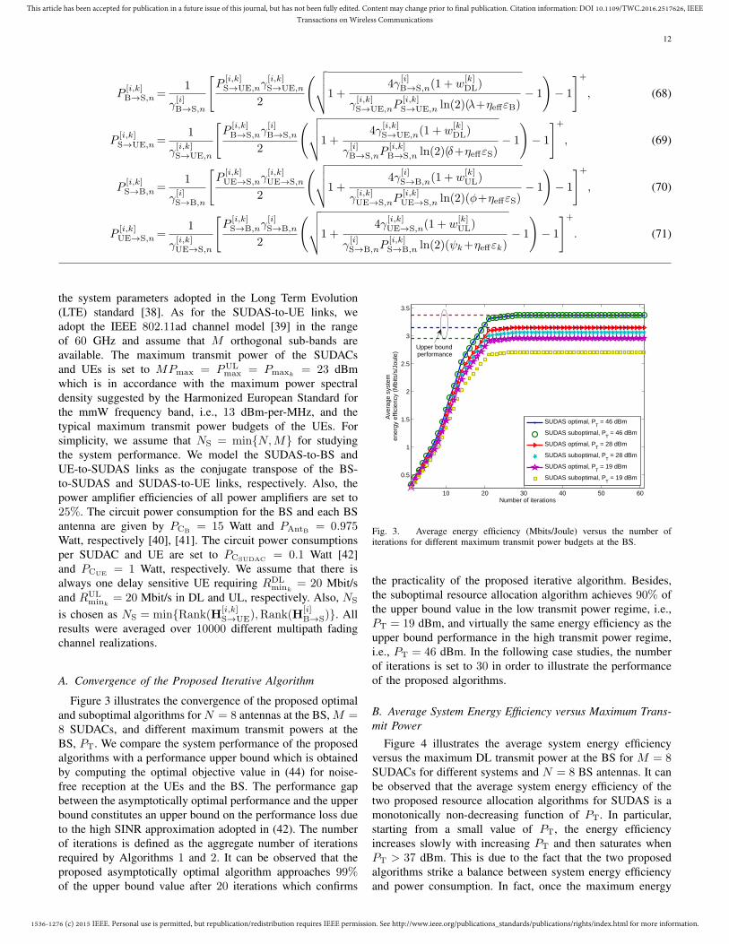
Figure 3 illustrates the convergence of the proposed optimaland suboptimal algorithms for N = 8 antennas at the BS, M =8 SUDACs, and different maximum transmit powers at theBS, PT. We compare the system performance of the proposedalgorithms with a performance upper bound which is obtainedby computing the optimal objective value in (44) for noise-free reception at the UEs and the BS. The performance gapbetween the asymptotically optimal performance and the upperbound constitutes an upper bound on the performance loss dueto the high SINR approximation adopted in (42). The numberof iterations is defined as the aggregate number of iterationsrequired by Algorithms 1 and 2. It can be observed that theproposed asymptotically optimal algorithm approaches 99%of the upper bound value after 20 iterations which confirms
10 20 30 40 50 60
0.5
1
1.5
2
2.5
3
3.5
Number of iterations
Ave
rage
sys
tem
en
ergy
effi
cien
cy (
Mbi
ts/s
/Jou
le)
SUDAS optimal, PT = 46 dBm
SUDAS suboptimal, PT = 46 dBm
SUDAS optimal, PT = 28 dBm
SUDAS suboptimal, PT = 28 dBm
SUDAS optimal, PT = 19 dBm
SUDAS suboptimal, PT = 19 dBm
Upper boundperformance
Fig. 3. Average energy efficiency (Mbits/Joule) versus the number ofiterations for different maximum transmit power budgets at the BS.
the practicality of the proposed iterative algorithm. Besides,the suboptimal resource allocation algorithm achieves 90% ofthe upper bound value in the low transmit power regime, i.e.,PT = 19 dBm, and virtually the same energy efficiency as theupper bound performance in the high transmit power regime,i.e., PT = 46 dBm. In the following case studies, the numberof iterations is set to 30 in order to illustrate the performanceof the proposed algorithms.
B. Average System Energy Efficiency versus Maximum Trans-mit Power
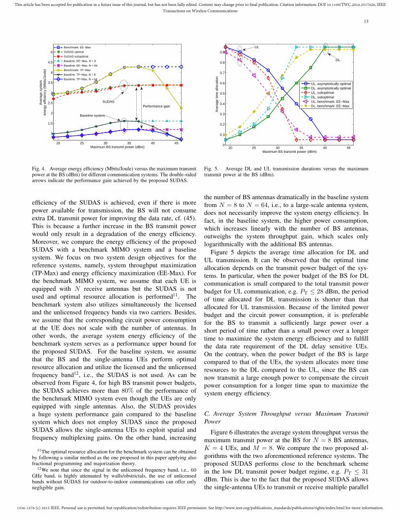
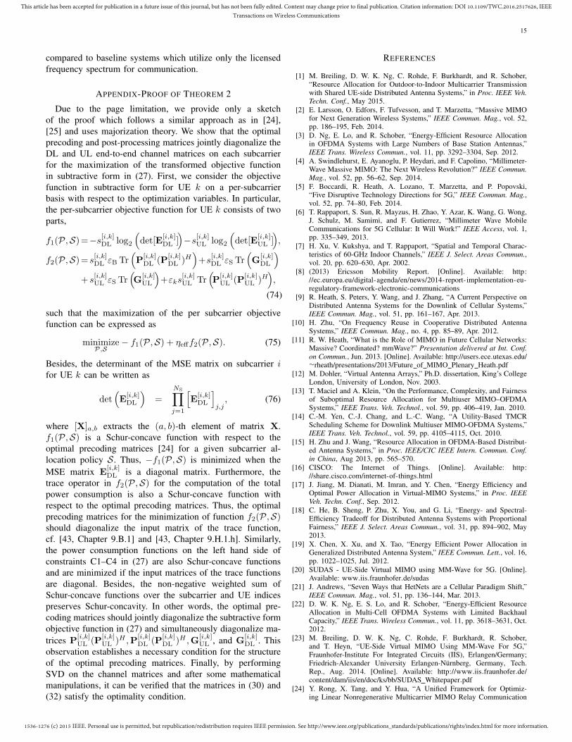
Figure 4 illustrates the average system energy efficiencyversus the maximum DL transmit power at the BS for M = 8SUDACs for different systems and N = 8 BS antennas. It canbe observed that the average system energy efficiency of thetwo proposed resource allocation algorithms for SUDAS is amonotonically non-decreasing function of PT. In particular,starting from a small value of PT, the energy efficiencyincreases slowly with increasing PT and then saturates whenPT > 37 dBm. This is due to the fact that the two proposedalgorithms strike a balance between system energy efficiencyand power consumption. In fact, once the maximum energy
1536-1276 (c) 2015 IEEE. Personal use is permitted, but republication/redistribution requires IEEE permission. See http://www.ieee.org/publications_standards/publications/rights/index.html for more information.
This article has been accepted for publication in a future issue of this journal, but has not been fully edited. Content may change prior to final publication. Citation information: DOI 10.1109/TWC.2016.2517626, IEEETransactions on Wireless Communications
13
20 25 30 35 40 45
1
1.5
2
2.5
3
3.5
4
4.5
5
Maximum BS transmit power (dBm)
Ave
rage
sys
tem
en
ergy
effi
cien
cy (
Mbi
ts/J
oule
)
Benchmark: EE−Max
SUDAS optimal
SUDAS suboptimal
Baseline: EE−Max, N = 8
Baseline: EE−Max, N = 64
Benchmark: TP−Max
Baseline: TP−Max, N = 8
Baseline: TP−Max, N = 64
Performance gainSUDAS
Baseline system
Fig. 4. Average energy efficiency (Mbits/Joule) versus the maximum transmitpower at the BS (dBm) for different communication systems. The double-sidedarrows indicate the performance gain achieved by the proposed SUDAS.
efficiency of the SUDAS is achieved, even if there is morepower available for transmission, the BS will not consumeextra DL transmit power for improving the data rate, cf. (45).This is because a further increase in the BS transmit powerwould only result in a degradation of the energy efficiency.Moreover, we compare the energy efficiency of the proposedSUDAS with a benchmark MIMO system and a baselinesystem. We focus on two system design objectives for thereference systems, namely, system throughput maximization(TP-Max) and energy efficiency maximization (EE-Max). Forthe benchmark MIMO system, we assume that each UE isequipped with N receive antennas but the SUDAS is notused and optimal resource allocation is performed11. Thebenchmark system also utilizes simultaneously the licensedand the unlicensed frequency bands via two carriers. Besides,we assume that the corresponding circuit power consumptionat the UE does not scale with the number of antennas. Inother words, the average system energy efficiency of thebenchmark system serves as a performance upper bound forthe proposed SUDAS. For the baseline system, we assumethat the BS and the single-antenna UEs perform optimalresource allocation and utilize the licensed and the unlicensedfrequency band12, i.e., the SUDAS is not used. As can beobserved from Figure 4, for high BS transmit power budgets,the SUDAS achieves more than 80% of the performance ofthe benchmark MIMO system even though the UEs are onlyequipped with single antennas. Also, the SUDAS providesa huge system performance gain compared to the baselinesystem which does not employ SUDAS since the proposedSUDAS allows the single-antenna UEs to exploit spatial andfrequency multiplexing gains. On the other hand, increasing
11The optimal resource allocation for the benchmark system can be obtainedby following a similar method as the one proposed in this paper applying alsofractional programming and majorization theory.
12We note that since the signal in the unlicensed frequency band, i.e., 60GHz band, is highly attenuated by walls/obstrictals, the use of unlicensedbands without SUDAS for outdoor-to-indoor communications can offer onlynegligible gain.
Fig. 5. Average DL and UL transmission durations versus the maximumtransmit power at the BS (dBm).
the number of BS antennas dramatically in the baseline systemfrom N = 8 to N = 64, i.e., to a large-scale antenna system,does not necessarily improve the system energy efficiency. Infact, in the baseline system, the higher power consumption,which increases linearly with the number of BS antennas,outweighs the system throughput gain, which scales onlylogarithmically with the additional BS antennas.
Figure 5 depicts the average time allocation for DL andUL transmission. It can be observed that the optimal timeallocation depends on the transmit power budget of the sys-tems. In particular, when the power budget of the BS for DLcommunication is small compared to the total transmit powerbudget for UL communication, e.g. PT ≤ 28 dBm, the periodof time allocated for DL transmission is shorter than thatallocated for UL transmission. Because of the limited powerbudget and the circuit power consumption, it is preferablefor the BS to transmit a sufficiently large power over ashort period of time rather than a small power over a longertime to maximize the system energy efficiency and to fulfillthe data rate requirement of the DL delay sensitive UEs.On the contrary, when the power budget of the BS is largecompared to that of the UEs, the system allocates more timeresources to the DL compared to the UL, since the BS cannow transmit a large enough power to compensate the circuitpower consumption for a longer time span to maximize thesystem energy efficiency.
C. Average System Throughput versus Maximum TransmitPower
Figure 6 illustrates the average system throughput versus themaximum transmit power at the BS for N = 8 BS antennas,K = 4 UEs, and M = 8. We compare the two proposed al-gorithms with the two aforementioned reference systems. Theproposed SUDAS performs close to the benchmark schemein the low DL transmit power budget regime, e.g. PT ≤ 31dBm. This is due to the fact that the proposed SUDAS allowsthe single-antenna UEs to transmit or receive multiple parallel
1536-1276 (c) 2015 IEEE. Personal use is permitted, but republication/redistribution requires IEEE permission. See http://www.ieee.org/publications_standards/publications/rights/index.html for more information.
This article has been accepted for publication in a future issue of this journal, but has not been fully edited. Content may change prior to final publication. Citation information: DOI 10.1109/TWC.2016.2517626, IEEETransactions on Wireless Communications
14
20 25 30 35 40 45
50
100
150
200
250
300
Maximum BS transmit power (dBm)
Ave
rage
tota
l sys
tem
thro
ughp
ut (
Mbi
ts/s
)
Benchmark: EE−MaxSUDAS optimalSUDAS suboptimalBaseline: EE−Max, N = 8Baseline: EE−Max, N = 64Benchmark: TP−MaxBaseline: TP−Max, N = 8Baseline: TP−Max, N = 64
Throughput gain
SUDAS
Fig. 6. Average system throughput (Mbits/s) versus the maximum transmitpower at the BS (dBm).
8 9 10 11 12 13 14 15 161
1.5
2
2.5
3
3.5
4
4.5
5
Number of SUDACs
Ave
rage
sys
tem
ene
rgy
effic
ienc
y (M
bits
/Jou
le)
Benchmark: EE−Max
SUDAS optimal
SUDAS suboptimal
Baseline: EE−Max, N = 8
Baseline: EE−Max, N = 64Baseline
SUDAS
Energy efficiencygain
Fig. 7. Average energy efficiency (Mbits/Joule) versus the number ofSUDACs.
data streams by utilizing the large bandwidth available inthe unlicensed band. Besides, for all considered systems, theaverage system throughput increases monotonically with themaximum DL transmit power PT. Yet, for the systems aimingat maximizing energy efficiency, the corresponding systemthroughput saturates in the high transmit power allowanceregime, i.e., PT ≥ 37 dBm. In fact, the energy-efficientSUDAS does not further increase the DL transmit power sincethe system throughput gain due to a higher transmit powercannot compensate for the increased transmit power, i.e., theenergy efficiency would decrease. As for the benchmark andbaseline systems aiming at system throughput maximization,the average system throughput increases with the DL transmitpower without saturation. For system throughput maximiza-tion, the BS always utilizes the entire available DL powerbudget. Yet, the increased system throughput comes at theexpense of a severely degraded system energy efficiency, cf.Figure 4.
8 9 10 11 12 13 14 15 1660
80
100
120
140
160
180
200
220
Number of SUDACs
Ave
rage
sys
tem
thro
ughp
ut (
Mbi
ts/s
)
Benchmark: EE−Max
SUDAS optimal
SUDAS suboptimal
Baseline: EE−Max, N = 8
Baseline: EE−Max, N = 64
Baseline
Throughputgain
SUDAS
Fig. 8. Average system throughput (Mbits/s) versus the number of SUDACs.
D. Average System Performance versus Number of SUDACs
Figures 7 and 8 illustrate the average energy efficiencyand throughput versus the number of SUDACs for N = 8BS antennas, PT = 37 dBm, and different systems. It canbe observed that both the system energy efficiency and thesystem throughput of the proposed SUDAS grow with thenumber of SUDACs, despite the increased power consumptionassociated with each additional SUDAC. For N ≥M , for DLtransmission, additional SUDACs facilitate a more efficientconversion of the spatial multiplexing gain in the licensedband to a frequency multiplexing gain in the unlicensed bandwhich leads to a significant data rate improvement. Similarly,for UL transmission, the SUDACs help in converting thefrequency multiplexing gain in the unlicensed band to a spatialmultiplexing gain in the licensed band. For M > N , increasingthe number of SUDACs in the system leads to more spatialdiversity which also improves energy efficiency and systemthroughput. Besides, a substantial performance gain can beachieved by the SUDAS compared to the baseline system foran increasing number of available SUDACs.
VI. CONCLUSIONS
In this paper, we studied the resource allocation algorithmdesign for SUDAS assisted outdoor-to-indoor communication.Specifically, the proposed SUDAS simultaneously utilizes li-censed and unlicensed frequency bands to facilitate spatial andfrequency multiplexing gains for single-antenna UEs in DLand UL, respectively. The resource allocation algorithm designwas formulated as a non-convex matrix optimization problem.In order to obtain a tractable solution, we revealed the structureof the optimal precoding matrices such that the problem couldbe transformed into a scalar optimization problem. Based onthis result, we proposed an asymptotically globally optimaland a suboptimal iterative resource allocation algorithm tosolve the problem by alternating optimization. Our simulationresults showed that the proposed SUDAS assisted transmissionprovides substantial energy efficiency and throughput gains
1536-1276 (c) 2015 IEEE. Personal use is permitted, but republication/redistribution requires IEEE permission. See http://www.ieee.org/publications_standards/publications/rights/index.html for more information.
This article has been accepted for publication in a future issue of this journal, but has not been fully edited. Content may change prior to final publication. Citation information: DOI 10.1109/TWC.2016.2517626, IEEETransactions on Wireless Communications
15
compared to baseline systems which utilize only the licensedfrequency spectrum for communication.
APPENDIX-PROOF OF THEOREM 2
Due to the page limitation, we provide only a sketchof the proof which follows a similar approach as in [24],[25] and uses majorization theory. We show that the optimalprecoding and post-processing matrices jointly diagonalize theDL and UL end-to-end channel matrices on each subcarrierfor the maximization of the transformed objective functionin subtractive form in (27). First, we consider the objectivefunction in subtractive form for UE k on a per-subcarrierbasis with respect to the optimization variables. In particular,the per-subcarrier objective function for UE k consists of twoparts,
f1(P,S)=−s[i,k]DL log2
(det[E
[i,k]DL ]
)−s[i,k]UL log2
(det[E
[i,k]UL ]
),
f2(P,S)= s[i,k]DL εB Tr(P
[i,k]DL (P
[i,k]DL )H
)+s
[i,k]DL εS Tr
(G
[i,k]DL
)+ s
[i,k]UL εS Tr
(G
[i,k]UL
)+εks
[i,k]UL Tr
(P
[i,k]UL (P
[i,k]UL )H
),
(74)
such that the maximization of the per subcarrier objectivefunction can be expressed as
minimizeP,S
− f1(P,S) + ηefff2(P,S). (75)
Besides, the determinant of the MSE matrix on subcarrier ifor UE k can be written as
det(E
[i,k]DL
)=
NS∏j=1
[E
[i,k]DL
]j,j, (76)
where [X]a,b extracts the (a, b)-th element of matrix X.f1(P,S) is a Schur-concave function with respect to theoptimal precoding matrices [24] for a given subcarrier al-location policy S. Thus, −f1(P,S) is minimized when theMSE matrix E
[i,k]DL is a diagonal matrix. Furthermore, the
trace operator in f2(P,S) for the computation of the totalpower consumption is also a Schur-concave function withrespect to the optimal precoding matrices. Thus, the optimalprecoding matrices for the minimization of function f2(P,S)should diagonalize the input matrix of the trace function,cf. [43, Chapter 9.B.1] and [43, Chapter 9.H.1.h]. Similarly,the power consumption functions on the left hand side ofconstraints C1–C4 in (27) are also Schur-concave functionsand are minimized if the input matrices of the trace functionsare diagonal. Besides, the non-negative weighted sum ofSchur-concave functions over the subcarrier and UE indicespreserves Schur-concavity. In other words, the optimal pre-coding matrices should jointly diagonalize the subtractive formobjective function in (27) and simultaneously diagonalize ma-trices P
[i,k]UL (P
[i,k]UL )H ,P
[i,k]DL (P
[i,k]DL )H ,G
[i,k]UL , and G
[i,k]DL . This
observation establishes a necessary condition for the structureof the optimal precoding matrices. Finally, by performingSVD on the channel matrices and after some mathematicalmanipulations, it can be verified that the matrices in (30) and(32) satisfy the optimality condition.
REFERENCES
[1] M. Breiling, D. W. K. Ng, C. Rohde, F. Burkhardt, and R. Schober,“Resource Allocation for Outdoor-to-Indoor Multicarrier Transmissionwith Shared UE-side Distributed Antenna Systems,” in Proc. IEEE Veh.Techn. Conf., May 2015.
[2] E. Larsson, O. Edfors, F. Tufvesson, and T. Marzetta, “Massive MIMOfor Next Generation Wireless Systems,” IEEE Commun. Mag., vol. 52,pp. 186–195, Feb. 2014.
[3] D. Ng, E. Lo, and R. Schober, “Energy-Efficient Resource Allocationin OFDMA Systems with Large Numbers of Base Station Antennas,”IEEE Trans. Wireless Commun., vol. 11, pp. 3292–3304, Sep. 2012.
[4] A. Swindlehurst, E. Ayanoglu, P. Heydari, and F. Capolino, “Millimeter-Wave Massive MIMO: The Next Wireless Revolution?” IEEE Commun.Mag., vol. 52, pp. 56–62, Sep. 2014.
[5] F. Boccardi, R. Heath, A. Lozano, T. Marzetta, and P. Popovski,“Five Disruptive Technology Directions for 5G,” IEEE Commun. Mag.,vol. 52, pp. 74–80, Feb. 2014.
[6] T. Rappaport, S. Sun, R. Mayzus, H. Zhao, Y. Azar, K. Wang, G. Wong,J. Schulz, M. Samimi, and F. Gutierrez, “Millimeter Wave MobileCommunications for 5G Cellular: It Will Work!” IEEE Access, vol. 1,pp. 335–349, 2013.
[7] H. Xu, V. Kukshya, and T. Rappaport, “Spatial and Temporal Charac-teristics of 60-GHz Indoor Channels,” IEEE J. Select. Areas Commun.,vol. 20, pp. 620–630, Apr. 2002.
[8] (2013) Ericsson Mobility Report. [Online]. Available: http://ec.europa.eu/digital-agenda/en/news/2014-report-implementation-eu-regulatory-framework-electronic-communications
[9] R. Heath, S. Peters, Y. Wang, and J. Zhang, “A Current Perspective onDistributed Antenna Systems for the Downlink of Cellular Systems,”IEEE Commun. Mag., vol. 51, pp. 161–167, Apr. 2013.
[10] H. Zhu, “On Frequency Reuse in Cooperative Distributed AntennaSystems,” IEEE Commun. Mag., no. 4, pp. 85–89, Apr. 2012.
[11] R. W. Heath, “What is the Role of MIMO in Future Cellular Networks:Massive? Coordinated? mmWave?” Presentation delivered at Int. Conf.on Commun., Jun. 2013. [Online]. Available: http://users.ece.utexas.edu/∼rheath/presentations/2013/Future of MIMO Plenary Heath.pdf
[12] M. Dohler, “Virtual Antenna Arrays,” Ph.D. dissertation, King’s CollegeLondon, University of London, Nov. 2003.
[13] T. Maciel and A. Klein, “On the Performance, Complexity, and Fairnessof Suboptimal Resource Allocation for Multiuser MIMO–OFDMASystems,” IEEE Trans. Veh. Technol., vol. 59, pp. 406–419, Jan. 2010.
[14] C.-M. Yen, C.-J. Chang, and L.-C. Wang, “A Utility-Based TMCRScheduling Scheme for Downlink Multiuser MIMO-OFDMA Systems,”IEEE Trans. Veh. Technol., vol. 59, pp. 4105–4115, Oct. 2010.
[15] H. Zhu and J. Wang, “Resource Allocation in OFDMA-Based Distribut-ed Antenna Systems,” in Proc. IEEE/CIC IEEE Intern. Commun. Conf.in China, Aug 2013, pp. 565–570.
[16] CISCO: The Internet of Things. [Online]. Available: http://share.cisco.com/internet-of-things.html
[17] J. Jiang, M. Dianati, M. Imran, and Y. Chen, “Energy Efficiency andOptimal Power Allocation in Virtual-MIMO Systems,” in Proc. IEEEVeh. Techn. Conf., Sep. 2012.
[18] C. He, B. Sheng, P. Zhu, X. You, and G. Li, “Energy- and Spectral-Efficiency Tradeoff for Distributed Antenna Systems with ProportionalFairness,” IEEE J. Select. Areas Commun., vol. 31, pp. 894–902, May2013.
[20] SUDAS - UE-Side Virtual MIMO using MM-Wave for 5G. [Online].Available: www.iis.fraunhofer.de/sudas
[21] J. Andrews, “Seven Ways that HetNets are a Cellular Paradigm Shift,”IEEE Commun. Mag., vol. 51, pp. 136–144, Mar. 2013.
[22] D. W. K. Ng, E. S. Lo, and R. Schober, “Energy-Efficient ResourceAllocation in Multi-Cell OFDMA Systems with Limited BackhaulCapacity,” IEEE Trans. Wireless Commun., vol. 11, pp. 3618–3631, Oct.2012.
[23] M. Breiling, D. W. K. Ng, C. Rohde, F. Burkhardt, R. Schober,and T. Heyn, “UE-Side Virtual MIMO Using MM-Wave For 5G,”Fraunhofer-Institute For Integrated Circuits (IIS), Erlangen/Germany;Friedrich-Alexander University Erlangen-Nurnberg, Germany, Tech.Rep., Aug. 2014. [Online]. Available: http://www.iis.fraunhofer.de/content/dam/iis/en/doc/ks/bb/SUDAS Whitepaper.pdf
[24] Y. Rong, X. Tang, and Y. Hua, “A Unified Framework for Optimiz-ing Linear Nonregenerative Multicarrier MIMO Relay Communication
1536-1276 (c) 2015 IEEE. Personal use is permitted, but republication/redistribution requires IEEE permission. See http://www.ieee.org/publications_standards/publications/rights/index.html for more information.
This article has been accepted for publication in a future issue of this journal, but has not been fully edited. Content may change prior to final publication. Citation information: DOI 10.1109/TWC.2016.2517626, IEEETransactions on Wireless Communications
16
Systems,” IEEE Trans. Signal Process., vol. 57, pp. 4837 – 4851, Dec.2009.
[25] D. W. K. Ng, E. S. Lo, and R. Schober, “Dynamic Resource Allocationin MIMO-OFDMA Systems with Full-Duplex and Hybrid Relaying,”IEEE Trans. Commun., vol. 60, pp. 1291–1304, May 2012.
[26] D. W. K. Ng and R. Schober, “Cross-Layer Scheduling for OFDMAAmplify-and-Forward Relay Networks,” IEEE Trans. Veh. Technol.,vol. 59, pp. 1443–1458, Mar. 2010.
[27] I. Hammerstrom and A. Wittneben, “Power Allocation Schemes forAmplify-and-Forward MIMO-OFDM Relay Links,” IEEE Trans. Wire-less Commun., vol. 6, pp. 2798–2802, Aug. 2007.
[28] W. Dinkelbach, “On Nonlinear Fractional Programming,” ManagementScience, vol. 13, pp. 492–498, Mar. 1967. [Online]. Available:http://www.jstor.org/stable/2627691
[29] D. Ng, E. Lo, and R. Schober, “Energy-Efficient Resource Allocationfor Secure OFDMA Systems,” IEEE Trans. Veh. Technol., vol. 61, pp.2572–2585, Jul. 2012.
[30] W. Yu and R. Lui, “Dual Methods for Nonconvex Spectrum Optimiza-tion of Multicarrier Systems,” IEEE Trans. Commun., vol. 54, pp. 1310– 1321, Jul. 2006.
[31] K. Seong, M. Mohseni, and J. Cioffi, “Optimal Resource Allocation forOFDMA Downlink Systems,” in Proc. IEEE Intern. Sympos. on Inf.Theory, Jul. 2006, pp. 1394–1398.
[32] S. Boyd and L.Vandenberghe, Convex Optimization. CambridgeUniversity Press, 2004.
[33] J. C. Bezdek and R. J. Hathaway, “Convergence of Alternating Op-timization,” Neural, Parallel and Sci. Comput., vol. 11, pp. 351–368,Dec. 2003.
[34] N. Papandreou and T. Antonakopoulos, “Bit and Power Allocation inConstrained Multicarrier Systems: The Single-user Case,” EURASIP J.Adv. Signal Process, vol. 2008, Jan. 2008.
[35] M. T. Heath, Scientific Computing: An Introductory Survey. McGraw-Hill, 2015.
[36] T. H. Cormen, C. E. Leiserson, R. L. Rivest, and C. Stein, Introductionto Algorithms, 3rd ed. The MIT Press, 2009.
[37] J. Meinila, P. Kyosti, L. Hentila, T. Jamsa, E. K. Essi Suikkanen,and M. Narandzic, “Wireless World Initiative New Radio WINNER+,D5.3: WINNER+ Final Channel Models,” CELTIC TelecommunicationSoultions, Tech. Rep.
[38] “Technical Specification Group Radio Access Network; Evolved U-niversal Terrestrial Radio Access (E-UTRA); Physical Channels andModulation (Release 8),” 3rd Generation Partnership Project, Tech. Rep.,3GPP, TS 36.211, V8.9.0.
[39] A. Maltsev, V. Erceg, E. Perahia, C. Hansen, R. Maslennikov, A. Lo-mayev, A. Sevastyanov, A. Khoryaev, G. Morozov, M. Jacob, T. K.S. Priebe, S. Kato, H. Sawada, K. Sato, and H. Harada, “Channel Modelsfor 60 GHz WLAN Systems,” IEEE Tech. Rep. 802.11-09/0334r8, Tech.Rep.
[40] O. Arnold, F. Richter, G. Fettweis, and O. Blume, “Power ConsumptionModeling of Different Base Station Types in Heterogeneous CellularNetworks,” in Proc. Future Network and Mobile Summit, 2010, pp. 1–8.
[41] R. Kumar and J. Gurugubelli, “How Green the LTE Technology Canbe?” in Intern. Conf. on Wireless Commun., Veh. Techn., Inform. Theoryand Aerosp. Electron. Syst. Techn., Mar. 2011.
[42] M. Miyahara, H. Sakaguchi, N. Shimasaki, and A. Matsuzawa, “An84 mW 0.36 mm2 Analog Baseband Circuits For 60 GHz WirelessTransceiver in 40 nm CMOS,” in Proc. IEEE Radio Freq. Integr. CircuitsSympos. (RFIC), Jun. 2012, pp. 495–498.
[43] A. W. Marshall and I. Olkin, Inequalities: Theory of Majorization andits Applications. New York: Academic Press, 1979.
Derrick Wing Kwan Ng (S’06-M’12) receivedthe bachelor degree with first class honors and theMaster of Philosophy (M.Phil.) degree in electron-ic engineering from the Hong Kong University ofScience and Technology (HKUST) in 2006 and2008, respectively. He received his Ph.D. degreefrom the University of British Columbia (UBC) in2012. In the summer of 2011 and spring of 2012,he was a visiting scholar at the Centre Tecnologicde Telecomunicacions de Catalunya - Hong Kong(CTTC-HK). He was a senior postdoctoral fellow
at the Institute for Digital Communications, Friedrich-Alexander-UniversityErlangen-Nurnberg (FAU), Germany. He is now working as a Lecturerat the University of New South Wales, Sydney, Australia. His researchinterests include convex and non-convex optimization, physical layer security,wireless information and power transfer, and green (energy-efficient) wirelesscommunications.
Dr. Ng received the Best Paper Awards at the IEEE Wireless Communica-tions and Networking Conference (WCNC) 2012, the IEEE Global Telecom-munication Conference (Globecom) 2011, and the IEEE Third InternationalConference on Communications and Networking in China 2008. He wasawarded the IEEE Student Travel Grants for attending the IEEE WCNC2010, the IEEE International Conference on Communications (ICC) 2011,and the IEEE Globecom 2011. He was also the recipient of the 2009 FourYear Doctoral Fellowship from the UBC, Sumida & Ichiro Yawata FoundationScholarship in 2008, and R&D Excellence Scholarship from the Center forWireless Information Technology in HKUST in 2006. He has served asan editorial assistant to the Editor-in-Chief of the IEEE Transactions onCommunications since Jan. 2012. He is currently an Editor of the IEEECommunications Letters. He was a Co-Chair for the Wireless Access Trackof 2014 IEEE 80th Vehicular Technology Conference. He has been a TPCmember of various conferences, including the Globecom, WCNC, ICC,VTC, and PIMRC, etc. He was honoured as the top reviewer of the IEEETransactions on Vehicular Technology in 2014 and an Exemplary Reviewerof the IEEE Wireless Communications Letters for 2012, 2014.
Marco Breiling was born in Birkenfeld/Nahe, Ger-many, in 1970. After conducting studies at the Uni-versitat Karlsruhe/Germany (now Karlsruhe Instituteof Technology KIT), the Norges Tekniske Høgskole(NTH) in Trondheim/Norway (now Norges Teknisk-Naturvitenskapelige Universitet NTNU), the EcoleSuperieure dIngenieurs en Electronique et Elec-trotechnique (ESIEE) in Paris, and the Universityof Southampton/England, he graduated with a Dipl.-Ing. (equivalent to master’s) degree from KIT in1997. He earned his PhD degree (with highest
honors) for a thesis about turbo codes from Friedrich-Alexander-UniversityErlangen-Nurnberg (FAU), Germany in 2002. Since 2001, he has beenworking at the Fraunhofer Institute for Integrated Circuits (IIS) in Erlangenin the field of digital communications. His special interests are channelcoding, iterative processing and virtual MIMO. He currently holds the chiefscientist position of the broadband & broadcast department. Moreover, he isa Distinguished Lecturer of the IEEE Broadcast Technology Society.
1536-1276 (c) 2015 IEEE. Personal use is permitted, but republication/redistribution requires IEEE permission. See http://www.ieee.org/publications_standards/publications/rights/index.html for more information.
This article has been accepted for publication in a future issue of this journal, but has not been fully edited. Content may change prior to final publication. Citation information: DOI 10.1109/TWC.2016.2517626, IEEETransactions on Wireless Communications
17
Christian Rohde was born in Erlangen, Germany,in 1979. He received his Diplom degree (Dipl.-Ing.)and his PhD degree (Dr.-Ing.) in electrical engi-neering from the Chair of Mobile Communication-s of the Friedrich-Alexander-University Erlangen-Nurnberg (FAU), Germany, in 2005 and 2013, re-spectively. Since his graduation, he is with the Com-munication Systems Division of the Fraunhofer In-stitute for Integrated Circuits IIS as a senior researchengineer. His research and development interestsinclude physical layer system design and algorithms
for receiver synchronization for both, single-carrier and multi-carrier trans-mission. Special focus is on adaptive channel estimation and equalizationalgorithms, which are robust against severe channel or interference conditionsand are of relevance for implementation. Since 2012, he is active memberof the technical module for satellite communications (TM-S) of the DigitalVideo Broadcasting Project (DVB) and has contributed to the standardizationof DVB-S2X.
Frank Burkhardt was born in Erlangen, Germany,in 1972. He received his Diplom degree (Dipl.-Ing.)in electrical engineering at the of the Friedrich-Alexander-University Erlangen-Nrnberg (FAU), Ger-many, in 2001. Since his graduation, he is with theCommunication Systems Division of the FraunhoferInstitute for Integrated Circuits IIS as a senior re-search engineer. His research and development inter-ests include design and implementation of softwaredefined radio systems (SDR) and modeling of radiopropagation channels.
Robert Schober (M’01, SM’08, F’10) was bornin Neuendettelsau, Germany, in 1971. He receivedthe Diplom (Univ.) and the Ph.D. degrees in elec-trical engineering from the University of Erlangen-Nuermberg in 1997 and 2000, respectively. FromMay 2001 to April 2002 he was a PostdoctoralFellow at the University of Toronto, Canada, spon-sored by the German Academic Exchange Service(DAAD). Since May 2002 he has been with theUniversity of British Columbia (UBC), Vancouver,Canada, where he is now a Full Professor. Since
January 2012 he is an Alexander von Humboldt Professor and the Chairfor Digital Communication at the Friedrich Alexander University (FAU),Erlangen, Germany. His research interests fall into the broad areas of Commu-nication Theory, Wireless Communications, and Statistical Signal Processing.
Dr. Schober received the 2002 Heinz MaierLeibnitz Award of the GermanScience Foundation (DFG), the 2004 Innovations Award of the VodafoneFoundation for Research in Mobile Communications, the 2006 UBC KillamResearch Prize, the 2007 Wilhelm Friedrich Bessel Research Award of theAlexander von Humboldt Foundation, the 2008 Charles McDowell Awardfor Excellence in Research from UBC, a 2011 Alexander von HumboldtProfessorship, and a 2012 NSERC E.W.R. Steacie Fellowship. In addition, hereceived best paper awards from the German Information Technology Society(ITG), the European Association for Signal, Speech and Image Processing(EURASIP), IEEE WCNC 2012, IEEE Globecom 2011, IEEE ICUWB2006, the International Zurich Seminar on Broadband Communications, andEuropean Wireless 2000. Dr. Schober is a Fellow of the Canadian Academyof Engineering and a Fellow of the Engineering Institute of Canada. He iscurrently the Editor-in-Chief of the IEEE Transactions on Communications.