EERC® Energy & Environmental Research Center — ort 23rd Street — Stop 9018/Grand Forks, ND 58202-9018 / Phone: (701) 777-5000 Fax: 777-5181 Web Site: www.undeerc.org June 21, 2012 Dr. Michael Berndt Research Scientist Division of Lands and Minerals Minnesota Department of Natural Resources 500 Lafayette Road Saint Paul, MN 55 155-4045 Dear Dr. Berndt: Subject: Revised EERC Final Report Entitled “Continuation of Corrosion Potential of Bromide Injection under Taconite Operating Conditions”; EERC Fund 15727 Enclosed please find the subject Energy & Environmental Research Center (EERC) revised final report. If you have any questions, please contact me by phone at (701) 777-5236 or by e-mail at yzhuang~undeerc.org. Sincerely, Ye Zhuang Research Manager YZsh Enclosure Printed on Recycled Paper
Transcript
EERC®Energy & Environmental Research Center
— ort 23rd Street — Stop 9018/Grand Forks, ND 58202-9018 / Phone: (701) 777-5000 Fax: 777-5181Web Site: www.undeerc.org
June 21, 2012
Dr. Michael BerndtResearch ScientistDivision of Lands and MineralsMinnesota Department of Natural Resources500 Lafayette RoadSaint Paul, MN 55 155-4045
Dear Dr. Berndt:
Subject: Revised EERC Final Report Entitled “Continuation of Corrosion Potential of BromideInjection under Taconite Operating Conditions”; EERC Fund 15727
Enclosed please find the subject Energy & Environmental Research Center (EERC)revised final report. If you have any questions, please contact me by phone at (701) 777-5236 orby e-mail at yzhuang~undeerc.org.
Sincerely,
Ye ZhuangResearch Manager
YZsh
Enclosure
Printed on Recycled Paper
CONTINUATION OF CORROSION POTENTIAL OF BROMIDE INJECTION UNDER TACONITE OPERATING CONDITIONS Revised Final Report Prepared for: Michael Berndt Division of Lands and Minerals Minnesota Department of Natural Resources 500 Lafayette Road Saint Paul, MN 55155-4045
Prepared by:
Ye Zhuang David J. Dunham
John H. Pavlish
Energy & Environmental Research Center University of North Dakota
15 North 23rd Street, Stop 9018 Grand Forks, ND 58201-9018
2012-EERC-06-07 June 2012
EERC DISCLAIMER LEGAL NOTICE This research report was prepared by the Energy & Environmental
Research Center (EERC), an agency of the University of North Dakota, as an account of work sponsored by Minnesota Department of Natural Resources. Because of the research nature of the work performed, neither the EERC nor any of its employees makes any warranty, express or implied, or assumes any legal liability or responsibility for the accuracy, completeness, or usefulness of any information, apparatus, product, or process disclosed or represents that its use would not infringe privately owned rights. Reference herein to any specific commercial product, process, or service by trade name, trademark, manufacturer, or otherwise does not necessarily constitute or imply its endorsement or recommendation by the EERC.
i
TABLE OF CONTENTS
LIST OF FIGURES ........................................................................................................................ ii LIST OF TABLES ......................................................................................................................... iv
LIST OF FIGURES 1 Temperature cycle in hot zone .............................................................................................. 4 2 Temperature cycle in cool zone ............................................................................................ 4 3 Halogen-induced active oxidation mechanisms .................................................................... 7 4 Phase-stability diagrams of Fe–O2–Br2 and Fe–O2–Cl2 ........................................................ 7 5 Phase-stability diagrams of Ni–O2–Br2 and Ni–O2–Cl2 ........................................................ 8 6 Phase-stability diagrams of Cr–O2–Br2 and Cr–O2–Cl2 ........................................................ 9 7 Phase-stability diagrams of Minntac–O2–Br2 and Minntac–O2–Cl2 ................................... 10 8 Morphology of the Minntac coupon prior to the test: unpolished surface and
polished surface ................................................................................................................... 12 9 Morphology of Minorca coupon prior to the test: unpolished surface and polished
surface ................................................................................................................................. 13 10 Surface morphology of the low-carbon steel coupon prior to the test ................................ 14 11 Surface of the Minorca coupon after exposure to HCl and HBr ......................................... 15 12 Cross section of the Minorca coupon after HCl exposure................................................... 15 13 Cross section of the Minorca coupon after HBr exposure .................................................. 16 14 Variation of Fe, Cr, and Ni across the Minorca coupon ..................................................... 17 15 Surface of the Minntac coupon after exposure to HCl and HBr ......................................... 18 16 Cross section of the Minntac coupon after HCl exposure ................................................... 18 17 Cross section of the Minntac coupon after HBr exposure ................................................... 19 18 Variation of Fe, Cr, and Ni across the Minntac coupon ...................................................... 20 19 Surface of low-carbon steel coupon after exposure ............................................................ 21 20 Cross section of the low-carbon steel coupon after HCl exposure ..................................... 22
Continued…
iii
LIST OF FIGURES (continued)
21 Cross section of the low-carbon steel coupon after HBr exposure ..................................... 22 22 Variation of Fe across the low-carbon steel coupon ........................................................... 23 23 Changes of specimen weight during the thermal cycle exposure ....................................... 23 24 Projected material loss over 3 years of operation ............................................................... 24
iv
LIST OF TABLES 1 Simulated Taconite Flue Gas Composition ........................................................................... 5 2 Experimental Parameters of Exposure Test .......................................................................... 6 3 Summary of T4, Melting Point, and Volatility Rank of Metal Compounds ....................... 10 4 Elemental Composition of the Testing Coupons ................................................................. 11
1
CONTINUATION OF CORROSION POTENTIAL OF BROMIDE INJECTION UNDER TACONITE OPERATING CONDITIONS
BACKGROUND The state of Minnesota is targeting an overall 90% mercury reduction. As a result, mercury emissions from taconite plants, the second largest mercury source next to coal-fired utility plants, have to be reduced to meet the state mercury reduction goal. Among various mercury reduction technologies being developed, halogens, such as chlorine and bromine, have been widely applied and proven effective to convert elemental mercury (Hg0) to either oxidized mercury (Hg2+) and/or particulate-bound mercury (Hg[p]) in coal flue gas environments (1–4). Both Hg(p) and Hg2+ then can be removed from the gas stream with particulate matter control devices and/or wet scrubbers. Both chloride and bromide compounds have been added into the induration furnace, the green ball feed system, and the scrubber liquids to evaluate their effectiveness on mercury reduction in taconite flue gas (5–7). So far, mercury reduction using bromine has shown to be the most promising and cost-effective control option that can be directly applied to taconite facilities. One major concern about applying halogens such as bromide or chloride as a mercury reduction agent is that they could induce corrosion and/or accelerate corrosion rates on taconite processing equipment, such as the feed grate and ducting system. Extensive studies have been performed to understand chlorine-induced corrosion in coal combustion environments. It is well accepted that HCl will attack metal surfaces at temperatures over 200C through the following reactions (8):
4 2 2 [Rea. 1]
, [Rea. 2]
[Rea. 3]
[Rea. 4] At the metal oxide interface where the oxygen partial pressure is low, metal chlorides are the thermoequilibrium-preferred reaction products. Depending on the temperature dependence of the vapor pressure with formed metal chlorides, the chlorides evaporate and diffuse toward the gas–scale interface. Within the scale, the oxygen partial pressure increases, and upon reaching regions with higher oxygen partial pressures, the gaseous chlorides will react with oxygen to form solid oxides, releasing gaseous chlorine, described as active oxidation corrosion. For temperatures below 100°C, dew point corrosion by hydrochloric acid occurs on metal surfaces. Bromine species do not naturally exist in taconite processing, and their corrosion characteristics on metal alloys are not well established. It has been proposed that bromine-induced corrosion is similar to that of chlorination and can be categorized as hydrobromic acid
2
dew point corrosion and active oxidation corrosion (9). Bromine-induced dew point corrosion occurs on metal surfaces because the flue gas temperatures are below a corresponding hydrobromic acid dew point. At temperatures over the hydrobromic acid dew point, active oxidation takes place as gaseous bromine diffuses through the oxide layer to the scale–metal interface where it reacts with base metals forming metallic bromides. For example, bromine species can react with iron to form iron bromide through the following reactions: Fe s Br2 g →FeBr2 s [Rea. 5]
Fe s 2HBr g →FeBr2 s H2 g [Rea. 6]
FeBr2 s →FeBr2 g [Rea. 7]
2FeBr2 g 3/2O2 g →Fe2O3 s 2Br2 g [Rea. 8]
4FeBr2 4HBr O2→4FeBr3 2H2O [Rea. 9]
4FeBr3 3O2→2Fe2O3 4Br2 [Rea. 10] In Reactions 8 and 10, the formed free bromine is either released to the bulk gas or diffuses back to the scale–metal interface, thus completing a cycle. Limited studies on bromine-induced corrosion were performed at static temperatures below 700C, not at representative taconite processing conditions (10). The EERC had previously performed a 30-day laboratory corrosion experiment to evaluate bromine-induced corrosion on taconite grate bars under temperatures of 500°, 300°, and 150°C (11). Postanalysis indicates minor bromine deposition and losses of Fe, Cr, and Ni from the testing coupons; however, the corrosion was mainly confined to the coupon surface. However, these corrosion experiments were conducted under static temperature conditions while actual taconite equipments experience thermal cycling, which may magnify and accelerate corrosion and greatly impact the test results. Therefore, these preliminary data are not necessarily enough to provide a complete perspective of possible bromine-induced corrosion in actual taconite processing conditions. Based upon feedback from the taconite industry, the Energy & Environmental Research Center (EERC) proposed additional bench-scale coupon corrosion tests with continuous thermal cycling under wider temperature regimes and extended exposure times. Moreover, materials other than grate bar, such as low-carbon alloy used in ducting systems, also need to be investigated for bromine corrosion under low-temperature regimes. The Phase II corrosion experiments performed by the EERC aim to help the taconite industry in understanding and evaluating the potential side effects that may result from applying bromide-related mercury control technology.
3
OBJECTIVES The overall goal of this project was to characterize bromine-induced corrosion on taconite processing equipment under simulated but representative taconite processing conditions. Specific objectives of this project included the following:
Determine Br-induced corrosion on grate bars and ductwork materials in simulated taconite flue gas containing HBr under thermal cycling conditions.
Compare the corrosion rates induced by bromine and chlorine.
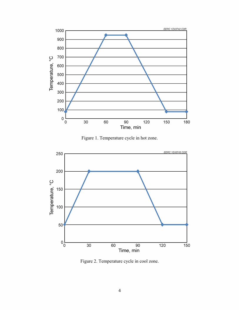
Estimate the life span of test coupons in taconite flue gas containing bromine species. EXPERIMENTAL APPROACH Mercury control technologies using bromine can be applied to either front-end furnace or downstream ductwork. Depending on the selected delivery methods, part of or the entire taconite facility may be exposed to gaseous bromine species and subjected to subsequent corrosion concerns. Therefore, the EERC performed a series of bench-scale corrosion experiments to assess the potential of bromine-induced corrosion on a taconite facility over widely varied temperatures. Select metal coupons were placed in a temperature-controlled chamber filled with simulated taconite flue gas containing HBr and, in a parallel stream, containing HCl. The exposure chamber was divided into two different temperature zones: hot zone and cool zone. Representative grate bar and low-carbon steel coupons were tested in both the hot and cool zones. The temperature profile was originally proposed as cycling between 500° and 1200°C hourly in the hot zone to mimic the heat profile of grate bars experienced in the actual taconite processing condition, while temperatures within the cool zone would be varied between 65° and 250°C daily to simulate downstream ductwork temperatures. At the start of the project, the EERC revised the temperature cycling profiles based on a request from the taconite industry. As for the hot zone, temperatures varied from 80° to 950°C within a 3-hour cycle: 1 hour heating up, a half hour at peak temperature, 1 hour cooling off, and a half hour at a lower temperature, as plotted in Figure 1. The temperature cycle in the cool zone was revised to be varied from 50° to 200°C within a 2½-hour cycle: a half hour heating up, 1 hour at peak temperature, a half hour cooling off, and a half hour at a lower temperature, as plotted in Figure 2. At the request of the taconite industry, instead of one grate coupon originally proposed, two different grate coupons (Minorca and Minntac) were included in the corrosion experiment under the hot-zone condition. The grate bar coupons were provided by the taconite industry. The Minorca coupon has 5% Ni, 27% Cr, and balanced Fe content compared to 17% Ni, 27% Cr, and balanced Fe content in Minntac coupons. The grate bar coupons in the hot zone were covered with an iron oxide–limestone mixture to simulate the taconite processing environment. The low-carbon steel coupons (C1018) were obtained from ASPI Inc.
4
Figure 1. Temperature cycle in hot zone.
Figure 2. Temperature cycle in cool zone.
5
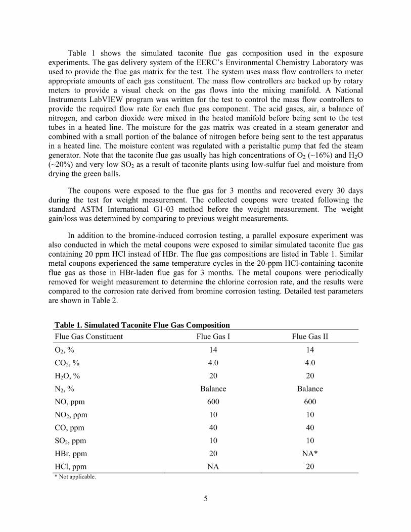
Table 1 shows the simulated taconite flue gas composition used in the exposure experiments. The gas delivery system of the EERC’s Environmental Chemistry Laboratory was used to provide the flue gas matrix for the test. The system uses mass flow controllers to meter appropriate amounts of each gas constituent. The mass flow controllers are backed up by rotary meters to provide a visual check on the gas flows into the mixing manifold. A National Instruments LabVIEW program was written for the test to control the mass flow controllers to provide the required flow rate for each flue gas component. The acid gases, air, a balance of nitrogen, and carbon dioxide were mixed in the heated manifold before being sent to the test tubes in a heated line. The moisture for the gas matrix was created in a steam generator and combined with a small portion of the balance of nitrogen before being sent to the test apparatus in a heated line. The moisture content was regulated with a peristaltic pump that fed the steam generator. Note that the taconite flue gas usually has high concentrations of O2 (~16%) and H2O (~20%) and very low SO2 as a result of taconite plants using low-sulfur fuel and moisture from drying the green balls. The coupons were exposed to the flue gas for 3 months and recovered every 30 days during the test for weight measurement. The collected coupons were treated following the standard ASTM International G1-03 method before the weight measurement. The weight gain/loss was determined by comparing to previous weight measurements. In addition to the bromine-induced corrosion testing, a parallel exposure experiment was also conducted in which the metal coupons were exposed to similar simulated taconite flue gas containing 20 ppm HCl instead of HBr. The flue gas compositions are listed in Table 1. Similar metal coupons experienced the same temperature cycles in the 20-ppm HCl-containing taconite flue gas as those in HBr-laden flue gas for 3 months. The metal coupons were periodically removed for weight measurement to determine the chlorine corrosion rate, and the results were compared to the corrosion rate derived from bromine corrosion testing. Detailed test parameters are shown in Table 2.
Table 1. Simulated Taconite Flue Gas Composition
Flue Gas Constituent Flue Gas I Flue Gas II
O2, % 14 14
CO2, % 4.0 4.0
H2O, % 20 20
N2, % Balance Balance
NO, ppm 600 600
NO2, ppm 10 10
CO, ppm 40 40
SO2, ppm 10 10
HBr, ppm 20 NA*
HCl, ppm NA 20 * Not applicable.
6
Table 2. Experimental Parameters of Exposure Test
Test No. Temperature Zone Exposure
Time Flue Gas
Composition Coupon Material Deposit
T-1 80°–950°C (3-hour cycle)
3 months Flue gas I Grate bar Iron oxide/ limestone
T-2 80°–950°C (3-hour cycle)
3 months Flue gas II Grate bar Iron oxide/ limestone
T-3 50°–200°C (2.5-hour cycle)
3 months Flue gas I Low-carbon steel
None
T-4 50°–200°C (2.5-hour cycle)
3 months Flue gas II Low-carbon steel
None
At the end of the exposure experiments, the recovered metal coupons were analyzed for morphology as well as the elemental compositions.
THERMODYNAMIC PERSPECTIVE The main corrosion mechanism induced by halogens on metal is that the formed metal chlorides or metal bromides are much more volatile than the corresponding metal oxides. At high temperature, metal halides at the metal oxide interface evaporate and diffuse outward. As a result, a nonprotective scale layer is subsequently formed, allowing a pathway for the halogens to contact the metal subsurface continuously. The temperature, oxygen/halogen ratio, and metal matrix of the material will influence corrosion behavior. Figure 3 shows the halogen corrosion mechanisms, as discussed earlier. Plotted in Figures 4–6 are the thermodynamic phase-stability diagrams that were constructed under metal–oxygen–chlorine and metal–oxygen–bromine systems for iron, nickel, and chromium, respectively, which are the three main elements of taconite grate materials. Since temperatures play a critical role in metal corrosion, the phase-stability diagrams were plotted at 500 and 950C, respectively. Also included in the phase-stability diagrams are the points representing the oxygen and bromine or chlorine partial pressure of the experimental gas conditions, marked as the square dots. For all three elements being considered at 500C, the scale formed on the scale–gas interface were predominantly oxides because of the high partial pressure of oxygen in the taconite flue gas: 14% O2 vs. 20 ppm HCl or HBr. However, halides could be thermodynamically favored as the oxygen potential was reduced, for example, at the scale–metal interface. Based on the phase-stability diagrams, the predominant metal compounds at low oxygen conditions, i.e., scale–metal interface, are FeBr2/FeCl2, Ni/NiBr2/NiCl2, and CrBr2/CrCl2/CrCl3 for Fe, Ni, and Cr, respectively. Most formed metal halides remained at their solid states at 500C, implying that active oxidation should be at minimum levels. The calculated results under 500°C condition agreed with the experimental observations in Phase I, in which only minor Br-induced corrosion was detected on the surface of the coupon exposed below 500°C.
7
Figure 3. Halogen-induced active oxidation mechanisms.
Figure 4. Phase-stability diagrams of Fe–O2–Br2 and Fe–O2–Cl2.
8
Figure 5. Phase-stability diagrams of Ni–O2–Br2 and Ni–O2–Cl2. With the temperature increasing to 950C, FeBr2 becomes vapor, and FeCl2 changes to liquid with elevated vapor pressure under low oxygen conditions, which could affect corrosion progress. It is expected that FeBr2 would diffuse outward through the oxide layer, cause spallation of the oxide layer, and form blisters. Similar outward diffusion with subsequent active oxidation can occur for FeCl2, while the extent of corrosion is less severe than that caused by FeBr2 since a lesser amount of gaseous FeCl2 is formed than FeBr2. FeBr2 or FeCl2 that reaches the scale–gas interface can convert to oxides such as Fe2O3/FeO/Fe3O4, as shown in the phase diagram and other reports (10), because of the high oxygen potential. The halogens that are released by conversion will reenter the gas phase and be available once again for exposure to metals. The phase diagrams indicate that NiO solid is predominant on metal surfaces at 950°C, while Ni remains in an elemental state at a low oxygen potential for bromine, and NiCl2 is formed predominantly as a solid with chlorine exposure. Nickel seems to be immune to a bromine reaction at 950°C. CrBr2 solid is thermodynamically stable, while CrCl2 in a liquid phase becomes the dominant chloride compound at a low oxygen potential under 950°C. Formed CrBr2 and CrCl2 can convert to oxide at a much lower oxygen partial pressure than needed to convert nickel bromide and chloride to nickel oxide.
9
Figure 6. Phase-stability diagrams of Cr–O2–Br2 and Cr–O2–Cl2. For a taconite grate bar that consists of varying amounts of Fe–Cr–Ni, a complex metal oxide scale is the predominant compound on the metal–gas interface, as shown in Figure 7 and reported by others (12). The extent of active oxidation heavily depends on the volatilization of the formed compounds, which can be characterized by temperature T4, defined as the temperature at which the vapor pressure reaches 10-4 atm. It is widely agreed that as the exposure temperature exceeds the corresponding T4, active oxidation becomes the dominant corrosion mechanism (13). Table 3 lists the T4 and melting points of metal bromides, chlorides, and oxides that could be formed in the taconite process according to the phase-stability diagrams. Note that the T4s of the formed chloride, bromide, and oxide compounds are higher than 500°C, which indicates that the quantities of the volatile species produced and diffused outward to the gas stream are expected to be small at temperatures below 500°C. As a result, the oxide
10
Figure 7. Phase-stability diagrams of Minntac–O2–Br2 and Minntac–O2–Cl2.
Table 3. Summary of T4, Melting Point, and Volatility Rank of Metal Compounds Metal Compounds T4, C Melting Point, C Volatility Rank FeBr2 509 689 1 FeCl2 536 677 2 NiBr2 567 963 3 NiCl2 587 1009 4 CrCl3 607 1152 5 CrBr2 716 NA 6 CrCl2 747 824 7 Fe2O3 NA 1565 8 NiO NA 1955 9 Cr2O3 NA 2435 10
11
scale will remain intact and minimize further chlorine- or bromine-induced active oxidation. Slight weight gain is expected for the materials below this temperature because of halogen deposition, as observed for the testing coupons in Phase I exposure experiments where temperatures were controlled below 500°C. Similar observations have also been reported elsewhere (14). As shown in Table 3, the T4 of iron bromide/chloride is the lowest, followed with nickel bromide/chloride and chromium chloride/bromide, indicating that most metal bromides have relatively higher volatilities than the corresponding chloride followed by oxides. As the exposure temperature reaches 950°C, active oxidation would occur to some varying degrees for all three elements. It is estimated that iron would have poor resistance to halogens under the high-temperature condition, while bromine-induced corrosion on iron would be worse than that of chlorine. Chromium compound is much less mobile than Fe and Ni and easier to convert to chromium oxide, which forms a protective scale. Therefore, Cr is likely to be the most resistant to active oxidation induced by halogens, followed by Ni, with Fe having the least resistance to corrosion by halogens. RESULTS AND DISCUSSIONS
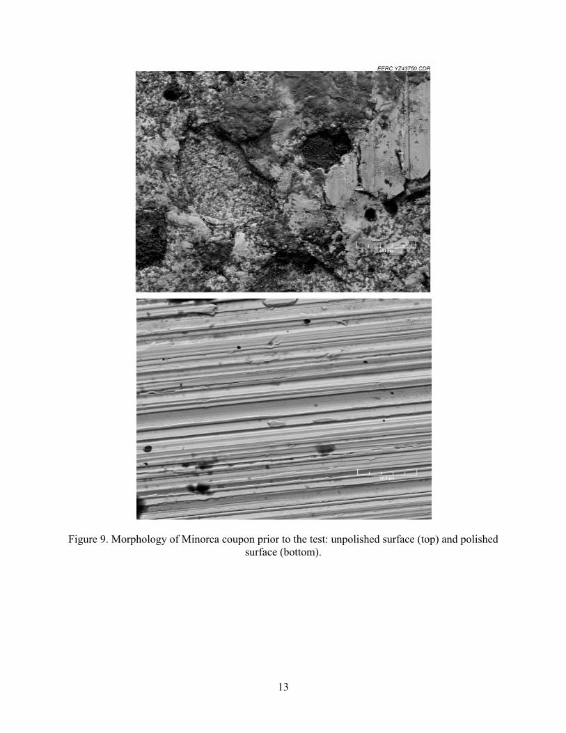
Preexposure Baseline Analysis Two taconite grate bars (Minntac and Minorca) and one low-carbon steel coupon were exposed in simulated taconite flue gas containing HBr and HCl for 3 months. Table 4 lists the main composition of each material prior to the test. The Minntac coupon has a much higher Ni content (9.92%–16.41%) than that of the Minorca coupon (1.3%–4.55%). Cr content was 31.61% for the Minntac coupon (polished side), slightly higher than the 26.58% between the two grate materials. Based upon the above thermodynamic calculations, it is expected that the Minntac coupon would be more resistant than the Minorca coupon to HCl and HBr attacks. The unpolished surface of the Minorca coupon has higher levels of Ca and Si impurities, and the impurities mainly remain on the surface in comparison to the polished surface. The low-carbon steel mainly consists of iron. As a result of high contents of Cr and Ni in the alloy, the heat-resistant grate bars are expected to have a better resistance to acid gases of HCl and HBr than the low-carbon steel. Morphology of the coupon surface prior to the exposure tests is referred to as the baseline (Figures 8–10).
Table 4. Elemental Composition of the Testing Coupons Coupon Type Fe Cr Ni Si Mo Ca Zr Minorca (unpolished) 61.25 22.64 1.30 4.48 0.26 5.48 4.16Minorca (polished) 66.58 26.58 4.55 1.30 0.14 0.11 0 Minntac (unpolished) 62.29 19.75 9.92 2.15 0.45 0.54 1.92Minntac (polished) 49.94 31.61 16.41 1.32 0.17 0.14 0.04Low-Carbon Steel 99.03 0.01 0.00 0.05 0.12 0 0
12
Figure 8. Morphology of the Minntac coupon prior to the test: unpolished surface (top) and polished surface (bottom).
13
Figure 9. Morphology of Minorca coupon prior to the test: unpolished surface (top) and polished
surface (bottom).
14
Figure 10. Surface morphology of the low-carbon steel coupon prior to the test.
Postexposure Analysis Upon completion of the 3-month exposure test, the coupons were removed and prepared for morphology and elemental analysis using scanning electron microscopy energy-dispersive spectroscopy. The results are discussed below.
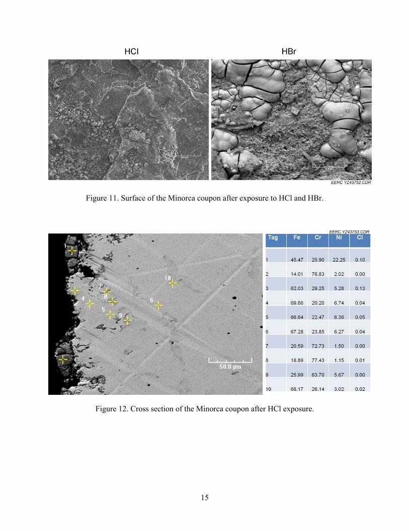
Minorca Coupon Shown in Figure 11 are the images of the Minorca coupon surface after 3 months of exposure to flue gas containing HCl and HBr. The coupon that has been exposed to the flue gas containing HCl virtually maintains its integrity on the surface after the 3-month test, which agrees with the corresponding cross-section analysis shown in Figure 12. A minor depletion of Fe was found on the scale–gas interface (Points 1 and 2), with corresponding enrichment of either Ni or Cr on the interface. Meanwhile, a slightly elevated Cl presence was also observed. According to thermodynamic calculation, even though FeCl2 might become volatile, the formed NiCl2 and CrCl2/CrCl3 would remain immobile as a solid phase under the current thermal cycle, and the scale would maintain its integrity. As a result, no significant cracking was observed beneath the surface, proving that the formed Fe–Cr–Ni complex scale is resistant to HCl attack and restricts chlorine-induced active oxidation within the interface.
On the other hand, the Minorca coupons exposed to HBr exhibited blistering and tiny
pinholes on the surface (shown in Figure 11), indicating volatiles emerged beneath the surface and were released through the scale during the exposure experiment. The corresponding cross-section morphology (Figure 13) shows that local microcracking developed beneath the scale.
15
Figure 11. Surface of the Minorca coupon after exposure to HCl and HBr.
Figure 12. Cross section of the Minorca coupon after HCl exposure.
16
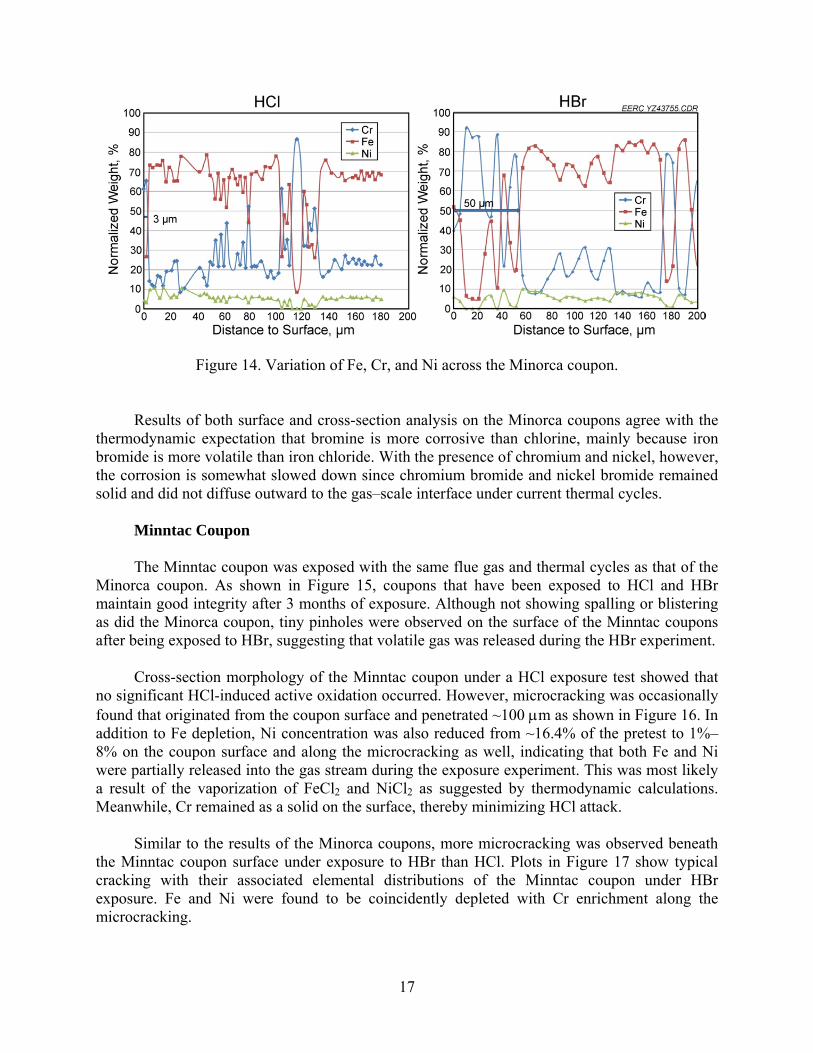
Figure 13. Cross section of the Minorca coupon after HBr exposure. Further elemental analysis on the selected points within the cross section indicates that Fe depletion took place not only within the scale but also along the microcracking beneath the surface. As a result of Fe depletion, the concentrations of Cr and Ni to some degree were elevated accordingly. At the metal subsurface with no oxygen presence, it is expected that metal bromides are formed, and iron bromide is the most volatile compared to chromium bromide and nickel bromide because of its low T4 among the three metal bromides. Therefore, a fair amount of iron bromide evaporated, diffused through the scale, and escaped into the gas stream. Meanwhile, chromium bromide and nickel bromide remained immobile as solids, resulting in the observed enrichment beneath the scale. The outward diffusion of iron bromide is believed to be the main reason for the local microcracking. At the scale–gas interface, metallic bromide compounds would be converted to oxides in the presence of oxygen, and bromine gas would be either released into the gas stream or diffused back to metal. Therefore, no bromine was detected within the scale. To further differentiate the impact of HCl and HBr on metal corrosion, elemental analysis of the three elements was performed along a randomly selected line within the cross section. As shown in Figure 14, the partitioning of Fe, Cr, and Ni for the coupon under HCl exposure was similar to that in the baseline condition. The coupon that was under HBr exposure showed appreciable Fe depletion with corresponding enrichment of Cr and/or Ni within the first 50 m from the scale–gas interface, and no significant changes of distribution of the three elements was observed beyond 200 m from the surface, indicating that bromine-induced corrosion was minor for the Minorca coupon under the testing conditions.
17
Figure 14. Variation of Fe, Cr, and Ni across the Minorca coupon.
Results of both surface and cross-section analysis on the Minorca coupons agree with the thermodynamic expectation that bromine is more corrosive than chlorine, mainly because iron bromide is more volatile than iron chloride. With the presence of chromium and nickel, however, the corrosion is somewhat slowed down since chromium bromide and nickel bromide remained solid and did not diffuse outward to the gas–scale interface under current thermal cycles.
Minntac Coupon The Minntac coupon was exposed with the same flue gas and thermal cycles as that of the Minorca coupon. As shown in Figure 15, coupons that have been exposed to HCl and HBr maintain good integrity after 3 months of exposure. Although not showing spalling or blistering as did the Minorca coupon, tiny pinholes were observed on the surface of the Minntac coupons after being exposed to HBr, suggesting that volatile gas was released during the HBr experiment.
Cross-section morphology of the Minntac coupon under a HCl exposure test showed that no significant HCl-induced active oxidation occurred. However, microcracking was occasionally found that originated from the coupon surface and penetrated ~100 m as shown in Figure 16. In addition to Fe depletion, Ni concentration was also reduced from ~16.4% of the pretest to 1%– 8% on the coupon surface and along the microcracking as well, indicating that both Fe and Ni were partially released into the gas stream during the exposure experiment. This was most likely a result of the vaporization of FeCl2 and NiCl2 as suggested by thermodynamic calculations. Meanwhile, Cr remained as a solid on the surface, thereby minimizing HCl attack. Similar to the results of the Minorca coupons, more microcracking was observed beneath the Minntac coupon surface under exposure to HBr than HCl. Plots in Figure 17 show typical cracking with their associated elemental distributions of the Minntac coupon under HBr exposure. Fe and Ni were found to be coincidently depleted with Cr enrichment along the microcracking.
18
Figure 15. Surface of the Minntac coupon after exposure to HCl and HBr.
Figure 16. Cross section of the Minntac coupon after HCl exposure.
19
Figure 17. Cross section of the Minntac coupon after HBr exposure.
20
As suggested by thermodynamic calculation, iron bromide that was formed beneath the surface in the absence of oxygen was the most volatile and evaporated through the scale, causing the depletion of Fe. Chromium bromide, the least volatile bromide compound, remained a solid and immobile within the coupon during the thermal cycle. In comparison to iron bromide and chromium bromide, nickel bromide has an intermediate volatility based upon its T4 and seemed to show some degree of volatilization, with a final Ni content along the crack stabilizing between 1% and 8%. At the scale–gas interface, metallic bromide compounds would be converted to oxides in the presence of oxygen, and bromine gas was either released into the gas stream or diffused back to metal. Therefore, no bromine was present within the scale. Elemental analysis along a randomly selected line was performed, and the resulting elemental distributions for the coupon exposed to HCl and HBr stream, respectively, are plotted in Figure 18. The elemental partitioning of the coupon exposed to HCl showed depletion of Fe and Ni with respective Cr enrichment for the first 5 m below the surface and recovered to the baseline condition, indicating resistance to HCl-induced corrosion. HBr, on the other hand, showed deeper ~20-m penetration through the coupons with enrichment of Cr and depletion of Fe and Ni. The coincident depletion of Fe and Ni seems to suggest that a Fe–Ni complex halide may be formed during the exposure. Further study on species of metal halides would facilitate an understanding of the reaction pathways. Since nickel bromide is less volatile than iron bromide and the iron content of the Minntac coupon is lower than the Minorca coupon, the overall active oxidation induced by HBr is less severe in the Minntac coupon than in the Minorca coupon, which explains why no obvious blistering was observed in the Minntac coupon surface. Both thermodynamic calculation and experimental data suggest that HBr is more corrosive than HCl to metals, and the experimental data from Minorca and Minntac coupons prove that, in comparison to Fe and Ni, Cr is the most resistant element to HCl and HBr attack during the present thermal cycle. Thermodynamic calculation also showed chromium chloride/bromide can convert to oxide at a very low oxygen partial pressure and a much higher oxygen partial pressure
Figure 18. Variation of Fe, Cr, and Ni across the Minntac coupon.
21
is needed to convert nickel chloride/bromide to nickel oxide. The presence of chromium on the coupon surface ensures the integrity of the formed protective scale and slows down or minimizes further HCl and/or HBr corrosion.
Low-Carbon Steel Plotted in Figures 19–22 are the morphology analysis (surface and cross section) with associated elemental distribution of the low-carbon steel coupons that have been exposed in HBr and HCl containing flue gas with temperature cycling between 50° and 200°C. Both low-carbon steel coupons showed no significant HCl- and/or HBr-induced blistering, and iron concentrations below the scale remained constant under the low-temperature thermal cycle. Cross-section morphology also indicated no microcracking below the scale. The likely explanation is that iron bromide and iron chloride remained solids, and no vaporization of metal bromide and chloride took place under the low-temperature thermal cycles. Loose condensate was found above the normal oxide scales of low-carbon steel coupons exposed to HBr streams (Figure 21). Further elemental analysis data showed that fair amounts of Ni and Br elements were detected within the condensate, indicating that nickel bromide compounds evaporated from the upstream heat-resistant coupons (Minorca and Minntac coupons) during the high-temperature cycles and recondensed on the low-carbon steel surface where the temperature was cycled between 50° and 200°C. All test coupons were periodically recovered during the exposure experiment for weight measurement, and the temporal variations of coupons weighed were plotted in Figure 23.
Figure 19. Surface of low-carbon steel coupon after exposure.
22
Figure 20. Cross section of the low-carbon steel coupon after HCl exposure.
Figure 21. Cross section of the low-carbon steel coupon after HBr exposure.
23
Figure 22. Variation of Fe across the low-carbon steel coupon.
Figure 23. Changes of specimen weight during the thermal cycle exposure.
Both the Minntac and Minorca coupons initially showed weight loss. However, after 30 days, the weight of the Minntac coupon became stable, while the Minorca coupon continuously lost weight until the end of the 3-month test, indicating that the Minntac coupon was more resistant to HCl/HBr corrosion than the Minorca coupon. Note that the Minorca coupon lost more weight during the third month of exposure than during the first 2 months; the reason is not clear. The Minntac coupon lost less weight than the Minorca coupon under the HBr
24
and HCl exposure experiment, respectively, mainly because the Minntac coupon has a higher chromium content than the Minorca coupon, which remained solid under the high-temperature cycle and prevented further weight loss. Another reason for the better corrosion resistance is the formation of chromium oxide scales with a significantly denser morphology. Accordingly, less diffusion paths exist for the transport of chlorine or bromine from the gas phase to the metal and for the transport of gaseous metal chlorides and bromide from the metal–scale interface outward, allowing less active oxidation. HBr clearly showed more impact on the weight change of coupons than HCl, suggesting that HBr resulted in more material loss than HCl when both were kept at the same levels. The reason is ascribed to a more volatile bromide compound that evaporated during the high-temperature thermal cycles.
The low-carbon steel coupon, under a low-temperature cycle, showed weight gain, initially followed with subsequent loss, then maintaining its weight at the end of the test. The projected material loss of test coupons over a 3-year operation were calculated based on the measured weight loss rate during the 3-month exposure test and a nominal density of 7.8 g/cm3; the results are plotted in Figure 24. While the Minntac coupons only show approximately 0.01 mm of material depletion under the exposure of HBr and HCl, the Minorca grate bar is expected to have 0.84 mm of material loss after a 3-year operation with HBr exposure in comparison to 0.4 mm of material loss in HCl environment. Low-carbon steel is not expected to show significant material depletion over a 3-year operation.
Figure 24. Projected material loss over 3 years of operation.
25
CONCLUSIONS Comparisons between bromine- and chlorine-induced metal corrosion were made under
simulated taconite operating conditions. Blisters and/or pinholes observed on the surface of the grate bar indicate that volatile compounds were formed, mainly iron chloride or iron bromide compounds. Temperature is very critical to corrosion, and the maximum temperature seems to be the most important factor.
Active oxidation appears to be the main corrosion mechanism under elevated temperatures of 500°‒950°C, while HBr showed a higher corrosion rate than HCl under similar simulated conditions. As a result, under the same level of halogen exposure with the same thermal cycles, both the Minntac and Minorca grate bar showed more microfracture and weight loss under the bromine condition compared to chlorine, while the main reasons for the weight loss can be ascribed to depletion of iron.
Based upon the measured data, the projected weight loss of Minntac and Minorca grate bar
over 3 years of operation under HBr conditions is marginal. Minorca grate bar is expected to have 0.84 mm of material depletion in comparison to 0.01 mm of material loss with Minntac grate bar.
No significant corrosion was observed for the low-carbon steel since it only experienced low
temperatures of 50°–200°C. The project weight loss over a 3-year operation under HBr conditions is minimum.
Note that the completed corrosion exposure tests were carried out in a bench-scale experimental system that cannot precisely simulate actual operating conditions in the taconite process. Therefore, the project results can be regarded as a first-step effort to address the potential bromine-induced corrosion as bromine is applied to the taconite facility for mercury reduction. Large-scale field testing is recommended in the future to account for the difference between bench-scale and full-scale systems. REFERENCES 1. Zhuang, Y.; Laumb, J.D.; Holmes, M.J.; Liggett, R.R.; Pavlish, J.H. Impacts of Acid Gases
on Mercury Oxidation Across SCR Catalyst. Fuel Process. Technol. 2007, 88, 929–934. 2. Zhuang, Y.; Thompson, J.S.; Zygarlicke, C.J.; Pavlish, J.H. Impact of Calcium Chloride
Addition on Mercury Transformations and Control in Coal Flue Gas. Fuel 2007, 86, 2351–2359.
Benson, S.A. A Status Review of Mercury Control Options for Coal-Fired Power Plants. Special Mercury Issue of Fuel Process. Technol. 2003, 82 (2–3), 89–165.
26
4. Liu, S.; Yan, N.; Liu, Z. Using Bromine Gas to Enhance Mercury Removal from Flue Gas of Coal-Fired Power Plants. Environ. Sci. Technol. 2007, 41 (4), 1405–1412.
5. Berndt, M.E.; Engesser, J. Mercury Transport in Taconite Processing Facilities: (III)
Control Method Test Results; Final Report to Iron Ore Cooperative Research; Minnesota Department of Natural Resources: Hibbing, MN, 2007.
6. Berndt, M.E. On the Measurement of Stack Emissions at Taconite Processing Plants;
Progress Report to Minnesota Control Agency; Minnesota Department of Natural Resources: Hibbing, MN, 2008.
7. Pavlish, J.H.; Zhuang, Y. Proof-of-Concept Testing of Novel Mercury Control Technology for a Minnesota Taconite Plant. Technical Report to Minnesota Department of Natural Resources; Energy & Environmental Research Center: Grand Forks, ND, 2008.
8. Zahs, A.; Spiegel, M.; Grabke, H.J. Chloridation and Oxidation of Iron, Chromium, Nickel
and their Alloys in Chloridizing and Oxidizing Atmospheres at 400±700°C. Corrosion Science 2000, 42, 1093–1122.
Associated with Mercury Control Technologies in Coal Flue Gas. Fuel 2009, 88, 1692–1697. 10. Lee, S.; Maemura, K.; Yamamura, T.; Nakazawa, S.; Lee, K.H.; Chang, D.; Ahn, J.-H.;
Chung, H. Corrosion Behavior of Metals in Flowing Ar–42.6% O2–14.7% Br2 Gas Mixture at 700°C. Corrosion Science Section 2006, 62 (1), 13–28.
11. Zhuang, Y.; Dunham, D.J.; Pavlish, J.H. Assessment of Potential Corrosion Induced by
Bromine Species Used for Mercury Reduction in a Taconite Facility; Report to Minnesota Department of Natural Resources; Energy & Environmental Research Center: Grand Forks, ND, 2009.
12. Stott, F.H.; Shih, C.Y. High-Temperature Corrosion of Iron-Chromium Alloys in Oxidizing-
Chloridizing Conditions. Oxidation of Metals 2000, 54 (5/6), 425–443. 13. Grabke, H.J.; Bryers, R.W. Incinerating Municipal and Industrial Waste. New York: