43
Energy from Waste and Recycling Facility Trident Park, Cardiff Planning Application Process Overview January 2010 SLR Ref: 407.0036.00306B

Energy from Waste and Recycling FacilityTrident Park, Cardiff
Planning ApplicationProcess Overview
January 2010 SLR Ref: 407.0036.00306B
Viridor i 402-0036-00306B Trident Park – Process Overview January 2010
SLR
100127 402-0036-00306b Process Overview
CONTENTS 1.0 INTRODUCTION............................................................................................................ 1
1.1 Facility Layout .................................................................................................... 1 1.2 Summary of Process Description..................................................................... 1
2.0 OVERVIEW OF CNIM TECHNICAL OPTIONS............................................................. 5 2.1 Introduction ........................................................................................................ 5 2.2 Reception and Waste Handling......................................................................... 5 2.3 Boiler and Power Generation ............................................................................ 6 2.4 Air Pollution Control Equipment..................................................................... 32 2.5 Ash Handling .................................................................................................... 38 2.6 SCADA System................................................................................................. 39 2.7 Electrical ........................................................................................................... 40
FIGURES
Figure 2-1 Waste Loading System ...................................................................................... 7 Figure 2-2 Waste Feeder ...................................................................................................... 9 Figure 2-3 Positioning and Design of the MARTIN Grate Bars....................................... 11 Figure 2-4 MARTIN Bottom Ash Discharger Schematic.................................................. 13 Figure 2-5 MARTIN Air Distribution Schematic................................................................ 14 Figure 2-6 Infrared and Video Imagery from Infrared Camera........................................ 16 Figure 2-7 Monitoring / Control of the Combustion Process Using an Infrared Camera
............................................................................................................................ 17 Figure 2-8 Structure of the Image Analysis Software...................................................... 18 Figure 2-9 Schematic Representation of the MARTIN Combustion Control System with
IR Camera........................................................................................................... 19 Figure 2-10 Influence of Stroke Adjustment Using IR Camera....................................... 20 Figure 2-11 Boiler Principle ............................................................................................... 24 Figure 2-12 Boiler System – Protection Against Corrosion............................................ 27 Figure 2-13 Schematic for Urea Injection ......................................................................... 34

Viridor ii 402-0036-00306B Trident Park – Process Overview January 2010
SLR
100127 402-0036-00306b Process Overview
Viridor 1 402-0036-00306B Trident Park – Process Overview January 2010
SLR
100127 402-0036-00306b Process Overview
1.0 INTRODUCTION
Viridor Waste Management Limited (Viridor) proposes to redevelop land formerly owned by Nippon Electric Glass (UK) Ltd as an Energy from Waste facility with a Combined Heat and Power plant, and ancillary offices (herein after referred to as an Energy from Waste (EfW) facility) at Trident Park, Glass Avenue, off Ocean Way, CardiffOverview
Trident Park is located some 1.6 kilometres to the south-east of Cardiff City Centre immediately north of the operational port of Cardiff. The application area is sited at Ordnance Survey Grid Reference 32030 17530, with access being gained from Ocean Way via Glass Avenue.
The application site area occupies some 4.5 hectares of the 20 hectare Trident Park development area. The site and its surroundings formed part of the East Moors Steelworks (that closed in 1978). Following its reclamation the Nippon Electric Glass (UK) Limited developed a cathode ray tube components factory on the land, which ceased production in 2005.
This planning application is being submitted on behalf of Viridor to operate an Energy from Waste (EfW) facility designed to accept 350,000 tonnes per annum of residual municipal solid waste, commercial and industrial waste. All waste accepted at the facility will be non-hazardous. The proposed facility will incorporate modern reliable and well understood combustion and pollution abatement technology. The plant will be designed in accordance with the requirements of the Waste Incineration Directive (WID89/76/EEC) and will employ Best Available Techniques as required by the Environmental Permitting regime.
1.1 Facility Layout
The proposed EfW facility will be totally enclosed within a purpose-built building that has been appropriately designed for its surroundings. The facility will comprise of the following elements;
• a waste reception area including a tipping hall and bunkers; • raw material and waste products storage silos; • two boilers and grates; • parallel flue gas treatment systems; • two stacks; • turbines and generators; • heat extraction infrastructure; • air cooled condensers; • electrical connections to the National Grid; • a visitors centre; • offices and ancillary areas; • a dedicated internal site access road network; • weighbridge and weighbridge office; • car-parking; and • HGV parking areas.
1.2 Summary of Process Description
The operation of the EfW facility will consist of five key elements described below:
• waste reception;

Viridor 2 402-0036-00306B Trident Park – Process Overview January 2010
SLR
100127 402-0036-00306b Process Overview
• pre-treatment (where required); • combustion; • energy recovery; • flue gas treatment; and • residue handling.
The technology to be implemented is known as moving grate technology, and the following describes the basic principles.
1.2.1 Waste Reception
The previously sorted residual waste will be delivered via Glass Avenue to a dedicated handling area using bulk transfer and street refuse collection vehicles (RCV’s). Where appropriate, vehicles using the site will be covered to ensure that waste and odour is not released to the environment in the journey to the site.
All vehicles delivering residual waste will be weighed when entering the site and proceed to a vehicle delivery and tipping hall where they will back up and discharge the waste into the refuse bunker. From here waste will be transferred to the two parallel “energy-from-waste” process lines and to each combustion chamber via dedicated feed chute and airlock sections using grab cranes.
The cranes will also be used to mix and break-up the incoming materials to ensure homogeneity of feed to the combustion chambers. A shredder will be provided to process any bulky household waste received in the hoppers and to reduce material to an appropriate size before returning shredded materials to the hoppers for processing.
Air will be drawn from the waste reception hall creating under pressure conditions. The extracted air will be used in the waste combustion process, which will help control odours arising in this area. This reception area will be enclosed with access doors and air louvers to manage traffic and air movements.
1.2.2 Combustion
Combustion will take place in two stages, with primary combustion undertaken on a moving mechanical grate to promote the mixing of burning/unburnt wastes. The combustion gas from the primary stage will be heated further in the secondary combustion chamber to reach the specified minimum temperature of 850°C for a minimum of two seconds. The burnt waste from primary combustion on the moving grate will be removed as an ash, known as Incinerator Bottom Ash (IBA).
1.2.3 Energy Recovery
The heat from combustion of the waste will be recovered initially to form steam and ultimately as electrical energy. When fully operational, the amount of heat exported from the facility will be around 50 Mega Watts, with approximately 20 Mega Watts of electrical energy exported to the grid. The heat that is produced will be recovered within a waste heat boiler to form high pressure steam, which will be used to drive turbines to generate electricity. A proportion of this site generated electrical energy will be used within the facility itself, but the majority will be exported to the National Grid.
The power generation and auxiliary equipment provided will include turbine/generator sets, air condensers and a heat recovery unit able to extract further energy from the partially cooled steam or hot water after it has been through the turbines.

Viridor 3 402-0036-00306B Trident Park – Process Overview January 2010
SLR
100127 402-0036-00306b Process Overview
1.2.4 Flue Gas Treatment
The air pollution control system will form an integral part of the plant and will treat all flue gas prior to emission to ensure that emissions will meet the stringent EU Waste Incineration Directive (WID) (2000/76/EC) standards.
The treatment of NOx will involve selective non-catalytic reduction (SNCR) using dry urea prills as the reagent. The process is a proven and widely used system of pollution abatement and will reduce the emissions from the facility to well within the stringent WID emission limits.
The flue gas treatment in the proposed facility will be a dry system, which will operate by injecting hydrated lime and activated carbon into the flue gases to control the pollutants. The gases will then be passed through a bag filter, which will remove reaction products and excess reagents, collectively known as air pollution control (APC) residues.
Residues collected in the final bag house filter process will be collected in hoppers, able to provide up to 3 days of storage.
1.2.5 Residue Handling
The EfW process will generate three main waste residues;
• incinerator bottom ash (IBA) and fly ash; • air pollution control (APC) residues; and • metals.
Incinerator Bottom Ash (IBA)
IBA will be generated from the grate combustion unit, and amounts to approximately 20 -25% of input material (approximately 75,000 tonnes per annum at Trident Park). Boiler dust and fly ash collected in the hoppers from the boiler passes will be combined with IBA and the mixed material can be used in concrete and concrete block construction, replacing up to 50% of the aggregate traditionally used.
IBA has also been used successfully in the sub-base and roadbase layers in road construction, after a process of hot asphalt stabilisation and mixing with cement or bitumen. The sub-base and roadbase layers refer to the intermediate layers of the road, below the final surface wearing course and above the lowest subgrade layer.
Viridor has entered into initial discussions with building material manufacturers to explore the opportunity for recycling this material.
Air Pollution Control Residues (APCRs)
The APCRs comprise flue gas treatment residues from the bag filters and will consist of the flue gas treatment chemicals (activated carbon and hydrated lime) with extracted contaminants (heavy metals, organics and inorganic salts). APCR represents about 2 – 3.5% by mass of the waste feedstock (approximately 10,500 tonnes per annum at Trident Park), and will be disposed of safely (by enclosed tanker) to a designated hazardous waste landfill.
The bulk of the APCRs will be spent hydrated lime reagent.

Viridor 4 402-0036-00306B Trident Park – Process Overview January 2010
SLR
100127 402-0036-00306b Process Overview
Metal Recovery
Following the combustion of waste, metals will be separated from the IBA by means of electromagnetic separators for ferrous metals, and eddy current separators for non-ferrous metals. This improves the composition of the IBA for after uses, and recovers valuable metals for recycling. The quantity of metal that can be recovered from the IBA is generally about 2.5% to 3% (approximately 8,750 tonnes per annum at Trident Park), depending on the waste feedstock, and thus represents a useful opportunity for significant amounts of metals recovery.
Viridor 5 402-0036-00306B Trident Park – Process Overview January 2010
SLR
100127 402-0036-00306b Process Overview
2.0 OVERVIEW OF CNIM TECHNICAL OPTIONS
2.1 Introduction
The following specification has been prepared based on information supplied by Constructions Industrielles de la Mediterranee (CNIM). The company has designed and constructed several currently operational energy from waste (EfW) facilities within the UK, as well as many throughout Western Europe.
All aspects of the EfW facility, including plant, equipment and civil, structural and building work, will be designed, manufactured, constructed and installed in accordance with all British statutory requirements, regulations, related technical guidance notes and codes of practice that are in force at the date of this document. Where possible, equipment for the facility will be sourced within the UK.
2.2 Reception and Waste Handling
The wastes entering the plant will arrive by refuse collection vehicles suitable for rear-unloading into the waste bunker. No links with railways or docks is feasible.
2.2.1 Weighbridges
Weighbridges will be provided at the Work’s entrance and exit roads. A computerised weighing control system will be provided, recording vehicle weights and enabling issuing of waste transfer notes with information on tare weight, gross weight, net weight, waste type, carrier identification, vehicle registration, vehicle type, etc. CCTV cameras will be positioned to view the front and rear of vehicles on each of the weighbridges. Audiovisual communication will be provided between the weighbridge and the central control room.
2.2.2 Waste Tipping Hall
The waste tipping hall will be fully enclosed and provided with louvres for natural air ventilation. Air for combustion will be drawn through the tipping hall creating under pressure conditions to minimise the escape of dust and odours.
Traffic lights will be provided to control traffic flows and avoid congestion.
2.2.3 Waste Bunker
The waste bunker will be designed to provide capacity at the normal waste discharge level without stacking. The minimum tipping bay width will be 7 metres for each vehicle unloading simultaneously, with the intention of providing up to 9 unloading bays.
The waste bunker has been sized to ensure 3 days of waste storage without stacking and almost 5 days with stacking.
2.2.4 Waste Cranes and Grabs
The two identical waste cranes will be designed for semi automatic and manual operation by two different operators from two separate operator positions. The waste cranes will be designed to mix, stack and cast shredded waste in the bunker and feed the hoppers to ensure consistent calorific value for feeding into the incinerator.
In semi automatic mode the crane will discharge the grab automatically into the pre-programmed feed hopper positions once the grab has been loaded by the operator.
Viridor 6 402-0036-00306B Trident Park – Process Overview January 2010
SLR
100127 402-0036-00306b Process Overview
Each crane and grab will be designed to transfer the delivered daily waste capacity into the feed hoppers in a 12 hour period. In addition, the crane and grab will be capable of further continuous operation for the remaining 12 hours of the day for lifting, moving, mixing, casting and stacking waste in the storage bunker.
The capacity of the grab will be sized to enable less than 35 grab loadings per hour during the 12 hour period.
The crane and grab will be capable of simultaneous operation in two directions in the horizontal plane whilst raising and lowering the grab in the vertical plane with appropriate design features to minimise grab swing.
A load cell based weighing system for the grab will be provided to enable the operator to record the weight of each grab load before discharge into the feed chute.
2.2.5 Shredder
The shredding system shall be designed to take bulky household waste and reduce it to a suitable size for input into the incinerator.
2.3 Boiler and Power Generation
Based on the anticipated throughput and Net Calorific Value (NCV) of the waste (also called LCV Lower Calorific Value or LHV Lower Heating Value), a three-run grate and vertical boiler arrangement will be used. The grate/boiler will be from a CNIM/MARTIN standard range of equipment and will optimise energy recovery and reduced NOx level in the raw gas.
The facility includes two combustion plants/heat recovery boilers (i.e. 2 parallel process lines), each designed to incinerate acceptable waste in a safe and environmentally sound manner.
2.3.1 Firing Capacity
The design point for this plant is a throughput of 22te/hr of MSW with a NCV of 9.3MJ/kg. Due to the flexible grate design, adjustments will be possible to accommodate a range of CVs. The design point and operating envelope for the plant is shown on the Stoker Grate Diagram attached as Appendix 1.
2.3.2 Combustion plant
Each Combustion Plant includes the following main components;
• waste loading system; • refuse transfer system; • refuse feeder; • incinerator MARTIN reverse acting grate system; • ash discharger; • combustion air distribution system; • grate sifting handling system; • hydraulic power system; • combustion air supply system; and • auxiliary fuel firing equipment (start up burners).
In accordance with normal practice the boiler fly ash (collected in hoppers at the bottom of the boiler passes) will be collected together with the bottom ash.
Viridor 7 402-0036-00306B Trident Park – Process Overview January 2010
SLR
100127 402-0036-00306b Process Overview
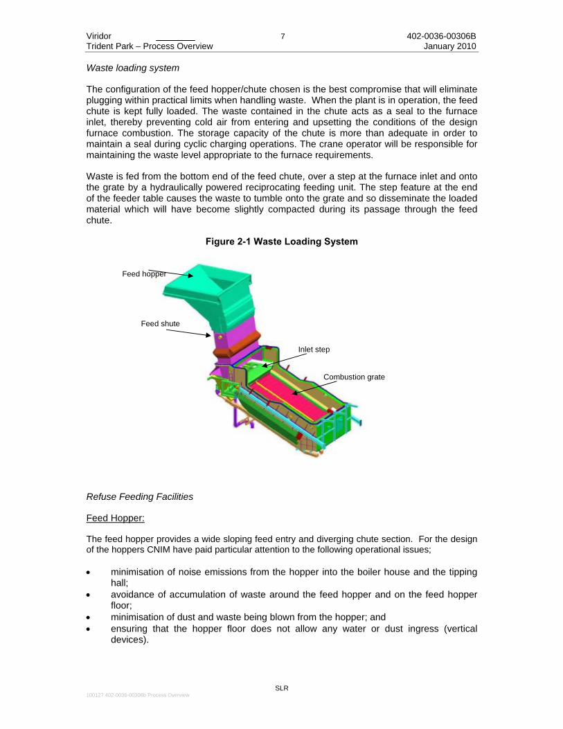
Waste loading system
The configuration of the feed hopper/chute chosen is the best compromise that will eliminate plugging within practical limits when handling waste. When the plant is in operation, the feed chute is kept fully loaded. The waste contained in the chute acts as a seal to the furnace inlet, thereby preventing cold air from entering and upsetting the conditions of the design furnace combustion. The storage capacity of the chute is more than adequate in order to maintain a seal during cyclic charging operations. The crane operator will be responsible for maintaining the waste level appropriate to the furnace requirements.
Waste is fed from the bottom end of the feed chute, over a step at the furnace inlet and onto the grate by a hydraulically powered reciprocating feeding unit. The step feature at the end of the feeder table causes the waste to tumble onto the grate and so disseminate the loaded material which will have become slightly compacted during its passage through the feed chute.
Figure 2-1 Waste Loading System
Refuse Feeding Facilities
Feed Hopper:
The feed hopper provides a wide sloping feed entry and diverging chute section. For the design of the hoppers CNIM have paid particular attention to the following operational issues; • minimisation of noise emissions from the hopper into the boiler house and the tipping
hall; • avoidance of accumulation of waste around the feed hopper and on the feed hopper
floor; • minimisation of dust and waste being blown from the hopper; and • ensuring that the hopper floor does not allow any water or dust ingress (vertical
devices).
Feed hopper
Feed shute
Inlet step
Combustion grate

Viridor 8 402-0036-00306B Trident Park – Process Overview January 2010
SLR
100127 402-0036-00306b Process Overview
The dimensions of the hopper are greater than those of the grab when fully open, and are such that sufficient clearance is always provided around the grab during feeding operations. The edges at the top of the hopper are around 1m above the surrounding floor to form a solid balustrade with free access on three sides for manual stroking if the hopper becomes obstructed by bulky waste. Stoking and clearing of the hoppers will not disturb the furnace feeding operations.
To reduce the noise generated by refuse falling into the hopper, an erosion proof rubber sheet is fitted inside the hopper to cushion the impact of falling waste. Feed Chute and Shut-Off Door:
The chute covers the full width of the furnace grate and is made of mild steel plate, suitably stiffened and adequately supported. The feed chute is slightly divergent from top to bottom to enable the waste to be more easily decompressed.
The shut off door is actuated by a hydraulic cylinder which is located in a recess at the top of the feed chute. The door is placed at the bottom of the hopper and is designed to resist mechanical and thermal stress. The hydraulic operation is remotely controlled from the control room with an automatic interlock.
All the components of the actuating system are located outside the feed chute.
Waste Feeder
The pusher is robustly constructed from high quality steel with a cast chrome steel nosing. Surface materials are designed to cater for the impact of refuse falling from the feed hopper. The pusher is supported at the rear on roller bearings and is moved back and forth by hydraulic cylinders. Parallel motion of the pusher is maintained by specially designed guides. A moveable end fixture compensates lateral expansion of the pusher resulting from temperature influence.

Viridor 9 402-0036-00306B Trident Park – Process Overview January 2010
SLR
100127 402-0036-00306b Process Overview
Figure 2-2 Waste Feeder
The nose of the pusher and the table are fitted with cast steel bars. Riddling passing through the bars are pneumatically conveyed to the ash discharger.
The flow of refuse entering the incineration grate can be adjusted by modulating; • the number of strokes per minute; and • the length of the stroke.
An oil leakage collecting tank is provided below the cylinders.
Incinerator Grate System
CNIM has selected for the project a MARTIN GMBH moving grate that gives consistently good performance with a wide range of waste types. As with the design of the whole works, the grate will have a long trouble-free life and is designed to operate safely and efficiently over a 20 years design life with minimum maintenance.
Purpose and General Features
The MARTIN grate is designed for mass burning and is unique in its concept, design and construction. It incorporates the following features;
Viridor 10 402-0036-00306B Trident Park – Process Overview January 2010
SLR
100127 402-0036-00306b Process Overview
• the moving grate bars are "reverse acting" to ensure good mixing, combustion and flame position control;
• the grate bars are made from high-grade alloy material to close tolerances; • the grate bars are shaped and have a special movement to reduce clinker formation;
and • expansion devices are incorporated which correctly maintain grate bar openings.
These features, all of which can be adjusted for control, enable the MARTIN grate to give a consistent performance with a wide range of waste types, and to have a long trouble free life.
These features also provide combustion control, which, in terms of quality and flame position, is essential for consistent boiler performance.
The "reverse action" of the grate bars prevents refuse from tumbling down the grate without ignition. The grate bars control its movement and constantly mix it, ensuring rapid drying of the incoming refuse, as the raw refuse is mixed with the burning mass. This movement has the effect of continuously rotating the mixing of the burning waste mass so that it is pushed back underneath the fresh fuel being fed onto the front end of the stoker grate. The constant turning of the burning mass enables a homogeneous bed to be formed and promotes a volatile fire at the head of the grate.
Further, the grate action prevents the formation of excessive hot spots and excessive clinker build-up. It is also this grate action that provides the high quality of burn out from the MARTIN system.
The close control of flame location enables the flame exit from the grate to be accurately placed in the furnace combustion area. It is into this area that the secondary over fire air is introduced. This and the shape of the furnace wall, result in a turbulent mixing action that prevents unburned gases and odours from escaping and being carried through to the chimney. This feature also helps to further reduce any paper char carry over.
Having controlled the main area of combustion, the bottom end of the grate provides an area for final burn out and a margin for better burning of dense objects. The grate bar elements are designed to carry out their function reliably and with a long life. They are made from machined high-grade chrome steel alloy castings and are capable of withstanding high temperatures. Thus a good fitting together of bars is achieved and the openings for combustion air accurately sized.
The gap between bars is limited to about 2% of the total grate incineration surface, through which an amount of siftings and fine ash fall. The standard MARTIN collecting system for these fines is built-in beneath the grate and feeds them into the bottom ash discharge system.
As a result of the MARTIN system of combustion control, the amount of unburned fines that falls through the grate is very small. The spacing between bars is accurately maintained by the use of expansion bars fitted to the sides of the grate. This allows the spacing to be maintained under varying temperature conditions.
Another important feature of the MARTIN grate is the combustion air system. Combustion air is supplied by a forced draught fan, which feeds into a compartmented plenum. The amount of air flowing into each compartment can be adjusted to meet the precise combustion requirements.

Viridor 11 402-0036-00306B Trident Park – Process Overview January 2010
SLR
100127 402-0036-00306b Process Overview
The primary air flows into the burning waste layer through gaps approximately 2 mm wide between heads of adjacent bars. These small air gaps form a very high resistance and ensure uniform air distribution over the surface of each grate zone. As a result of these design features, “craters” or cold spots do not occur in the refuse bed thus avoiding poor combustion and resulting high dust content in the flue gases.
This arrangement for distribution and control enables a constant pressure which ensures even distribution over the complete grate area.
A discharge mechanism, in the form of a roller, controls the rate of discharge and depth of the bed of burning refuse on the grate. This again can be adjusted and controlled for varying conditions.
Incineration Grate
The incinerator grate is set at an angle of 26° and consists of 3 run sections divided in steps.
The grate surface consists of high grade heat resisting chromium steel alloy grate bars and plates with very narrow apertures between the bars to control the air distribution over the full area of the grate.
Side faces of the bars are machined to achieve even, uniform widths of air gaps between adjacent bars and are arranged to prevent spreading of individual bars. At the side of the grate section, self-compensating expansion blocks are included to prevent binding of the grate bars due to heat expansion.
This enables a constant air gap to be maintained and ensures that the openings for combustion air are limited to approximately 2 % of the grate area surface. The openings in the MARTIN grate bar design are set at the front of the bar where combustion air spreads over the whole underside of the fire bed, regardless of any dense objects.
To break up clinker formation, some of the bars have a pyramid head fixed on top.
Figure 2-3 Positioning and Design of the MARTIN Grate Bars
A transverse carrier beam supported by main operating bars carried in permanently lubricated side thrust rollers hydraulically actuates the moveable bars.

Viridor 12 402-0036-00306B Trident Park – Process Overview January 2010
SLR
100127 402-0036-00306b Process Overview
Robust hydraulically operated pistons providing infinitely variable control of the reciprocating movement power the grate drive bars.
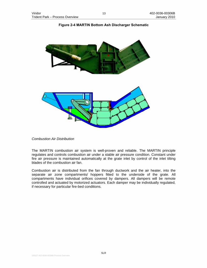
A central grease lubrication system will supply all lubrication points of the stoker and residue roller drive, refuse feeder and bottom ash discharger. Bottom Ash Discharger The MARTIN bottom ash discharger unit is a device especially developed for quenching and handling the bottom ash as shown in Figure 2-4. It has the following advantages; • is of extremely robust construction and designed for arduous duty and continuous
operation; • is compact and takes up little floor space; • is a small water trough, but this is more than adequate for residue quenching and
conditioning so that conveyors can then easily handle the residue; • has powerful reciprocating rams, hydraulically operated with variable speed control to
push out the residue at the desired rate; • has no chains or flights therefore: jamming problems are virtually eliminated and
furthermore, wearing problems are avoided; • provides a gas seal to the incinerator and prevents ingress of air and egress of dust
and fumes; and • has few mechanical components, therefore system reliability is dependable and
surveillance and maintenance are minimal. Water consumption is controlled at the optimum requirement for quenching and conditioning, so that when the residue is finally discharged, its water content is only about 15 to 20 % of the dry residue weight depending on residue quality.
The ash discharger is basically composed of two main parts, a structural steel body and a mechanical ram. It is robustly constructed in steel plate, heavily ribbed to form a watertight trough with surfaces exposed to the residue being covered with steel lining plates.
The trough is filled with process recycled water, and the water level is automatically maintained with a suitable level control device. This equipment is located so that maintenance operations can be carried out externally without difficulty.
Viridor 13 402-0036-00306B Trident Park – Process Overview January 2010
SLR
100127 402-0036-00306b Process Overview
Figure 2-4 MARTIN Bottom Ash Discharger Schematic
Combustion Air Distribution
The MARTIN combustion air system is well-proven and reliable. The MARTIN principle regulates and controls combustion air under a stable air pressure condition. Constant under fire air pressure is maintained automatically at the grate inlet by control of the inlet tilting blades of the combustion air fan.
Combustion air is distributed from the fan through ductwork and the air heater, into the separate air zone compartments/ hoppers fitted to the underside of the grate. All compartments have individual orifices covered by dampers. All dampers will be remote controlled and actuated by motorized actuators. Each damper may be individually regulated, if necessary for particular fire-bed conditions.

Viridor 14 402-0036-00306B Trident Park – Process Overview January 2010
SLR
100127 402-0036-00306b Process Overview
Figure 2-5 MARTIN Air Distribution Schematic
In order to improve the combustion efficiency and steam flow CNIM propose the integration of the IR camera.
The infrared camera is an innovative further development of the MARTIN combustion control system. It is integrated into the roof of the first boiler pass. The camera makes near-real time recordings of the fuel's surface temperature distribution on the combustion grate. The resulting data are processed by an image analysis program using arithmetic techniques, enabling effective elimination of disruptive gas and particle radiation.
Initial Situation
When combusting residual waste the goal is to achieve low-emission energy-efficient process control. Whilst the composition of unsorted household waste is heterogeneous, the residual MSW and commercial and industrial wastes that will be received at the facility will be more homogenous. However some variation will still occur and the MARTIN combustion control system is well suited to responding to, and minimising the environmental effects of, any variations in composition.
To ensure optimum combustion, the control system must be more dynamic and flexible so that the operating settings can be automatically adjusted to the changing combustion conditions without delays.
If characteristics such as heating value, moisture or shape/size of the pieces that make up the fuel should change, drying, ignition and combustion behaviour change correspondingly over time. Consequently, the heat release, temperatures and flue gas composition also fluctuate. Unexpected fuel fluctuations generally have a negative effect on burnout, flue gas composition and energy efficiency.
Viridor 15 402-0036-00306B Trident Park – Process Overview January 2010
SLR
100127 402-0036-00306b Process Overview
Fuel fluctuations interfere with the parameters for controlling flue gas oxygen content, combustion temperature and output. To optimize process control, the control loops of the combustion control system must:
• rapidly compensate for the effects of fuel fluctuations (adjustment of the actuating variables e.g. fuel flow, air flow and air distribution); and
• adjust its set points and partly also the intervention strategies to each fuel and the present combustion conditions in real time.
It is impossible to directly measure changes in fuel characteristics. Conclusions must therefore be drawn indirectly on the basis of fuel-induced changes in measurable variables. The classical MARTIN combustion control system can only capture the fuel-induced fluctuations with a time-delay and cannot localize them. It obtains control information mostly through line or point measurements as from gas temperature, oxygen content or air flows. It can be difficult to obtain a long-term representative recording of the process operations, in particular in the case of large and wide furnaces and boilers. It therefore makes sense to extract information relevant to the combustion process in 2-dimensional form and as close to the combustion process as possible, ideally at the point at which solid fuel is converted into heat. In this way, the problem of generating control signals to which a fast reaction is possible using the above measurement values for more uniform heat release (for maximum fuel throughput) is significantly reduced.
Objective
After recording the temporal and spatial behaviour of the fuel bed surface temperatures over area and processing the information obtained, there should be a reaction to the dynamic behaviour of fuel bed temperatures. This can be achieved mainly by supplying underfire air as required and varying its temperature in the various grate zones, but also by influencing the feeder.
Objectives for use of the IR camera system;
• increased uniformity of the combustion process; • more uniform release of heat from the fuel on the individual runs in relation to each
other; • smaller fluctuation margins for the gas flow and consequently also for the steam flow; • reduction of O2 peaks and consequently CO peaks; • higher average fuel bed temperatures; • constantly uniform good bottom ash burnout; • more uniform flow conditions in the first boiler pass; and therefore • positive influence on the efficiency of secondary combustion.
Solution
To implement the specified objectives, a measurement system that can determine and evaluate the fuel bed surface temperatures (grate zone 1 to middle grate zone 4) virtually in real time is required. The calculated signals are then sent on to the combustion control system.
An infrared camera installed centrally over the grate in the boiler roof facilitates fast, non-contact and non-reactive capture of the combustion situation at the required high local resolution. This in turn makes it possible to recognise changes at an early stage and to use this information for monitoring purposes or to selectively influence the combustion control system.

Viridor 16 402-0036-00306B Trident Park – Process Overview January 2010
SLR
100127 402-0036-00306b Process Overview
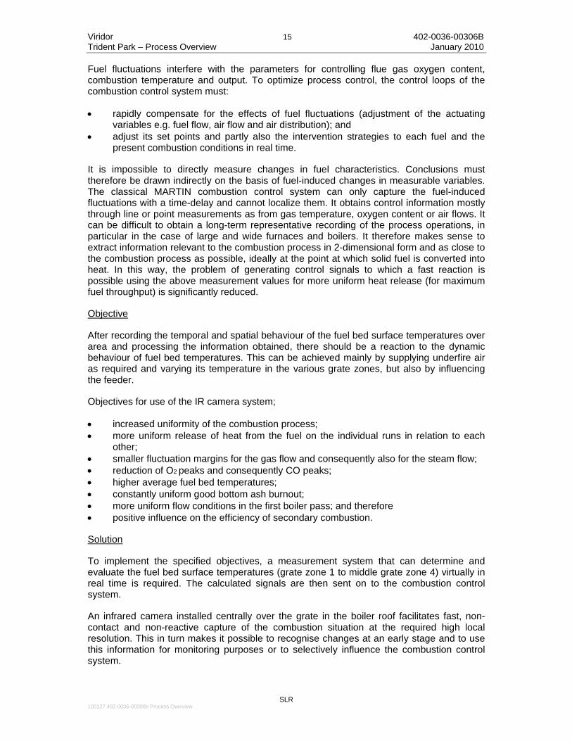
The infrared camera records the fuel bed surface temperatures from a high angle by means of radiation images in the form of a two-dimensional temperature profile over the fuel bed. From the perspective of the infrared camera, the (in relative terms) cold fuel bed surface lies behind a hot gas atmosphere. The gas atmosphere between the infrared camera and the fuel bed consists of various gases (mainly CO2, CO, NO(x)) and the composition of this atmosphere is permanently fluctuating. Each of these gases has its own emission characteristic for radiating by wave length and consequently the thermal radiation from the fuel bed to be measured can be distorted by the gas radiation.
Using what is known as a flame filter, the infrared camera's measurement window is set to an area in which the influence of the gas atmosphere is at its weakest, with the result that the disruptive gas radiation flows between the camera and the fuel bed are reduced to a negligible minimum in relation to the emission from the fuel bed. However, the above does not apply to unburned carbon (soot), which is also present between fuel bed and infrared camera. Accordingly, particle radiation emission (flame radiation), which is largely dependent on the particle flow and size, distorts the radiation information from the fuel bed.
Figure 2-6 Infrared and Video Imagery from Infrared Camera
An image processing facility downstream of the measurement device uses special arithmetic techniques to eliminate the disruptive influence of this particle radiation to the extent possible, with the result that the temperature of the fuel bed surface can be determined with a high level of reliability. This information is in turn used to generate the control signals required for the individual grate runs and grate zones. As offset values, they influence the distribution and temperature of the underfire air and also the fuel supply.

Viridor 17 402-0036-00306B Trident Park – Process Overview January 2010
SLR
100127 402-0036-00306b Process Overview
Figure 2-7 Monitoring / Control of the Combustion Process Using an Infrared Camera
The infrared camera is installed centrally over the grate in the boiler roof. The lens used is located in a furnace probe connected to the infrared camera. Both the infrared camera and furnace probe are either water or air-cooled. A sapphire glass window closes the furnace probe off from the furnace.
A retract system for withdrawing and introducing the camera and lens makes the system inherently safe. An alarm chain (cooling water flow/temperature and compressed air flow as well as condition inside the camera) monitors operation and automatically retracts the infrared camera and lens in the event of any danger. A remote supply cabinet with supply lines and a system cable going to the infrared camera is located nearby. Actuation of the retract system is exclusively pneumatic. The system has a buffer so that the camera can still be introduced (automatically) in the event of a complete blackout or total failure of the compressed air supply.
There is a remote supply cabinet for the camera and retract system. The cabinet also passes on alarms and the infrared images for image analysis.
Information is transferred between the infrared camera and remote supply cabinet via a fibre optic cable (for the infrared image and camera status reports) and a system cable (for monitoring/control of the retract system, power supply for the infrared camera). Information is transferred between the remote supply cabinet and the image analysis computer via a double-core optical fibre connection (for infrared images and infrared camera status reports). The collective alarm for the alarm chain to the bus system and therefore the DCS is transmitted via a conventional line.
The images from the infrared camera are taken up by a computer via a special board.
The image analysis software consists of a main module (INSPECT software), which in turn is surrounded by various other modules called gateways that serve to transfer signals. The main module communicates with its gateways exclusively by means of TCP/IP. The modules are independent of the operating system and predominantly in the accredited programming language ADA.

Viridor 18 402-0036-00306B Trident Park – Process Overview January 2010
SLR
100127 402-0036-00306b Process Overview
Figure 2-8 Structure of the Image Analysis Software
A fibre optic cable connects the infrared camera and image analysis computer, on which image analysis software developed by MARTIN is installed. The software performs in-depth analysis of the image information and generates control signals by means of mathematical/statistical operations.
The signals are then integrated into the MARTIN combustion control system.
In addition to the signals for generating control loops calculated by the software, the operating staff can obtain a wealth of information that would not otherwise be obtainable from the infrared images of the fuel bed on a MARTIN reverse-acting grate. The observer can make an immediate assessment of the combustion's quality by directly comparing the information to the other operating parameters.
As primary combustion on the grate is crucial to the overall combustion process emphasis was placed on developing a control system that would allow more direct capture of the combustion process. This development lead to the infrared-camera-guided combustion control system patented by MARTIN.
The idea on which this innovative control system is based is demand-oriented, temperature-regulated control of all underfire air over the entire fuel bed as a function of fuel consistency and heating value.
The following process engineering goals have been achieved;
• more uniform distribution of fuel bed temperatures between the individual runs; • increase in average fuel bed temperatures and therefore increased pollutant retention
rate in bottom ash and/or higher pollutant take-up in fly/boiler ash; and • reduction in combustion-related emissions.

Viridor 19 402-0036-00306B Trident Park – Process Overview January 2010
SLR
100127 402-0036-00306b Process Overview
Figure 2-9 Schematic Representation of the MARTIN Combustion Control System with IR Camera
The basic control loops of the classical MARTIN combustion control system remain the same with infrared camera control. The additional control loops are listed below.
Control loop - temperature compensation between the grate runs
Varying degrees of temperature difference may occur between the individual grates due to the heterogeneity of the fuel. These differences affect the gas and bottom ash burnout, flow profile in the first boiler pass, O2 stoichiometry and combustion uniformity.
Determination of the temperature differences between the individual runs makes it possible to distribute underfire air in a much more demand-oriented manner. The control loop for compensation of the fuel bed temperature between the individual runs affects combustion zones 2 and 3 (main combustion zone = point at which conversion of mass to heat is greatest).
Control loop – compensation of characteristic temperature imbalances by the feeder
Characteristic temperature imbalances that would be almost impossible to identify without an infrared camera may be caused on the grate by changes in the feeding sequence due to varying fuel qualities and by mechanical changes (wear on triangular brake plates, differing stroke lengths of the individual rams). The control loop for demand-oriented underfire air distribution cannot correct this situation, as its time behaviour is different. For this reason, the stroke of individual feed ram is adjusted in such a way that on average the amount of fuel fed over a longer period is brought into line with that fed by the other rams. This significantly reduces the temperature imbalance on the grate. Fig. 2.10 shows the influence of the adjustment in stroke on the uniformity of the temperature distribution over the grate width in the case of a long characteristic imbalance (via infrared camera).

Viridor 20 402-0036-00306B Trident Park – Process Overview January 2010
SLR
100127 402-0036-00306b Process Overview
Figure 2-10 Influence of Stroke Adjustment Using IR Camera
Control loop – adjustment of underfire air
The underfire air temperature can be used as a control variable to influence the position of the main combustion zone, i.e. the fuel bed length. When the fuel heating value is low, ignition is delayed and the fuel bed becomes longer. In order to maintain the main combustion zone in its ideal position (this fluctuates naturally depending on the waste's particular combustion behaviour), the underfire air temperature is normally increased with low heating value fuels to shorten the distance between the point at which fuel is fed and the area at which the highest temperatures prevail (main combustion zone). Accordingly, when heating value is high the underfire air temperature is reduced, to prevent early ignition and unnecessary fluctuations in heat release.
The air pre-heater must be adjustable for this control loop to function.
Control loop – Overfeed Control
If excessive amounts of fuel are fed and the fuel fails to ignite quickly enough, there is a risk of excess fuel build-up on the fuel bed.
To prevent overfeeding at low heating values, the degree of cover may be determined from the image information. Freshly fed waste is introduced to the main combustion zone based on the temperature and position information obtained. It is then possible to slow the feeding process and provide the fuel with enough time to dry and ignite should there be a risk of overfeeding. Summary The infrared camera installed in the roof of the 1st pass determines the distribution of the surface temperatures of the fuel on the grate virtually in real time. A comprehensive image analysis program using arithmetic techniques specially designed for MARTIN generates control signals using the recorded values. Disruptive gas and particle radiation is effectively eliminated by the arithmetic techniques. The IR camera records fuel bed surface temperatures in terms of time and location. The values obtained are therefore significantly more representative of the combustion process as it takes place than are the values obtained by measuring the temperatures or other relevant

Viridor 21 402-0036-00306B Trident Park – Process Overview January 2010
SLR
100127 402-0036-00306b Process Overview
flue gas variables. Based on the behaviour and distribution of the fuel bed surface temperatures, conclusions can be drawn for combustion control and appropriate control signals can be generated;
• heat release → underfire air distribution, fuel metering • temperature of main → burnout/sintering behaviour of the bottom ash • combustion zone • position of the main → fuel metering • combustion zone (per grate run). The infrared image also provides operating staff in the control room with visual information on the status of the combustion process. Use of the MARTIN infrared camera system has the following results; • heat release is more uniform; • temperature and flow conditions in the furnace are more uniform; • the average excess combustion air is reduced due to more selective distribution of the
underfire air; • good bottom ash burnout due to higher fuel bed temperatures; • stabilization of flue gas parameter behaviour; and • positive influence on plant operation. Grate Siftings Handling System
This system comprises a series of mild steel hoppers, each with a butterfly type outlet valve connected with an inclined duct terminating above the ash discharger.
The hoppers are situated beneath the grate section with one situated beneath the waste feeder device.
Siftings will be collected in the hoppers and cleared at intervals of 2 - 4 discharges per hour. The siftings will be conveyed pneumatically, using combustion air as a pressure medium, and delivered to the ash discharger.
The butterfly type valves will be operated pneumatically and are designed to prevent leakage of combustion air when in the shut position. Adequate facilities will be provided in the hopper compartments to enable access and inspection to be carried out without difficulties. The hopper outside surface will be lagged to ensure the maximum surface temperature does not exceed 60°C when the ambient is 25°C.
Hydraulic Power System
The moving grate steps, feed chute shut-off door, refuse feeder, discharge roller and bottom ash discharger are driven hydraulically through electro hydraulic controls to obtain the required individual speed variations.
One complete pumping station is provided to serve the hydraulic drives for the grate.
Combustion Air Supply
The combustion air is drawn from above the waste bunker, so that the odours and airborne dust are drawn from the tipping hall and/or the boiler house into the incineration line. The air intake over the bunker is fitted with a grid (coarse filter). The air velocity through the grid is

Viridor 22 402-0036-00306B Trident Park – Process Overview January 2010
SLR
100127 402-0036-00306b Process Overview
kept low, approximately 4m.s-1, in order to minimise clogging by paper, plastic sheets and other debris.
For each line, a duct is run from the air intake down to the forced draught fans. The forced draught fans discharge into two ducts;
• the main duct routing air through the air heater to the plenum under the MARTIN grate (primary air); and
• the second duct routing air directly to row of air nozzles on the front wall and on the rear wall (secondary air).
Forced Draught Fans
For the incineration line, two combustion fans (one for underfire and one for overfire air) are provided;
• the fan is a centrifugal type with an impeller overhung on the shaft. It is abrasion resistant, with self-cleaning blades; and
• a vortex, operated by a pneumatic actuator is created in the inlet vein to achieve the flow rates control. Drive is through direct flexible coupling.
Air Heater
One air steam heater will be provided to heat the combustion air up to a temperature that is dependent upon the calorific value of the waste. The heater will be designed and constructed to accommodate thermal expansion of the tube bundle and the casing. The air heater will be insulated with mineral wool in order that the external temperature does not exceed 70 °C. An inspection door is provided.
Auxiliary burner
The combustion chamber/boiler is provided with an auxiliary burner. The purpose of this is to;
• ignite the refuse at the start-up of the plant following shut down periods; and • for the purposes of complying with the EC Waste Incineration Directive on flue gas
emissions. This requires that the temperature must not fall below 850°C.
The auxiliary burner operates automatically to maintain the temperature so long as there is refuse on the grate. This burner is also used to raise the temperature in the combustion chamber prior to starting up from cold and during shutting down of the plant.
The total capacity of the burner will be rated at around 60% of the boiler design load. (around 40 MW). The burners will be gas oil / diesel oil fired.
The burner will be supplied complete with electric ignition, flame safeguard equipment, and a valve train, which contains control valves, instrumentation, isolation valves and a local control panel.
The system will be pre-piped and pre-wired to the maximum extent possible to minimize the amount of field installation. Diesel oil pulverisation will be performed by compressed air.
Viridor 23 402-0036-00306B Trident Park – Process Overview January 2010
SLR
100127 402-0036-00306b Process Overview
The flame detection system for the burners is a flame detector with a self-checking feature. The flame intensity is converted to an electrical signal, which is used to indicate flame status and initiate the appropriate response.
The equipment includes a local control panel as well as a dedicated safety PLC installed in the PLC room. The local control panel is capable of starting and stopping the burner sequencing through the PLC. The local control panel functions as a termination panel for the burner and valve train electrical devices and instruments.
Diesel oil will be stored in an above ground fully bunded tank. Transferring of the diesel oil at the set pressure to start-up burners and other users will be achieved by means of two (2 x 100%) AC motor driven pumps.
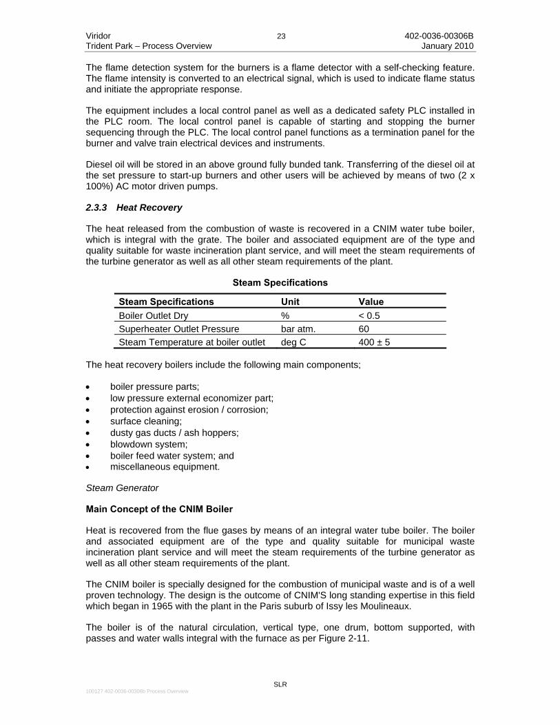
2.3.3 Heat Recovery
The heat released from the combustion of waste is recovered in a CNIM water tube boiler, which is integral with the grate. The boiler and associated equipment are of the type and quality suitable for waste incineration plant service, and will meet the steam requirements of the turbine generator as well as all other steam requirements of the plant.
Steam Specifications
Steam Specifications Unit Value Boiler Outlet Dry % < 0.5 Superheater Outlet Pressure bar atm. 60 Steam Temperature at boiler outlet deg C 400 ± 5
The heat recovery boilers include the following main components;
• boiler pressure parts; • low pressure external economizer part; • protection against erosion / corrosion; • surface cleaning; • dusty gas ducts / ash hoppers; • blowdown system; • boiler feed water system; and • miscellaneous equipment.
Steam Generator
Main Concept of the CNIM Boiler
Heat is recovered from the flue gases by means of an integral water tube boiler. The boiler and associated equipment are of the type and quality suitable for municipal waste incineration plant service and will meet the steam requirements of the turbine generator as well as all other steam requirements of the plant.
The CNIM boiler is specially designed for the combustion of municipal waste and is of a well proven technology. The design is the outcome of CNIM'S long standing expertise in this field which began in 1965 with the plant in the Paris suburb of Issy les Moulineaux.
The boiler is of the natural circulation, vertical type, one drum, bottom supported, with passes and water walls integral with the furnace as per Figure 2-11.

Viridor 24 402-0036-00306B Trident Park – Process Overview January 2010
SLR
100127 402-0036-00306b Process Overview
• 1st pass : radiant combustion chamber, empty vertical pass. • 2nd pass : vertical pass, with evaporator. • 3rd pass : vertical pass, with convective superheater & evaporator bundles. • 4th pass : vertical pass, with superheater & economiser bundles. • 5th pass : vertical pass, with economiser bundles.
An external low pressure economiser will be installed on the flue gas path above the economiser to reduce flue gas temperature to 140°C which is the optimum temperature for CNIM’s dry flue gas treatment. This design will also ensure a high efficiency of the thermal cycle and better electrical production.
Figure 2-11 Boiler Principle
The design of the boiler makes it particularly suitable for waste incineration. In order to prevent fouling, erosion and corrosion problems, the design has taken the following aspects into account; • proper design of the combustion chamber (shape, dimensions) to improve gas velocity
and temperature profiles; • low gas velocity in the combustion chamber to reduce ash carry over; • protection of water walls in the flame zone designed to achieve good heat transfer
without excessive inner face temperature; • wide spacing of tubes in convection tube banks; • on-line cleaning well adapted to the design; • easy access for inspection and maintenance of all pressure parts; and • on-line surface cleaning by a combination soot blowing rapping and vibrating.

Viridor 25 402-0036-00306B Trident Park – Process Overview January 2010
SLR
100127 402-0036-00306b Process Overview
Water Walls
All the evaporating tube panel elements have the same profile. Since all enclosure walls are at a uniform temperature, all expansion is uniform, and there are no possibilities of gas leaks causing damage to insulation or resulting in corrosion attack on the outer metal sheeting.
Steam Drum
The steam drum is of a transverse arrangement. It will be of fusion welded construction, X-ray tested, stress relieved and fabricated from steel plate, in accordance with standard industry practice.
Steam drum internals include;
• internal feed water pipe and supports; • continuous blow-down and chemical feed pipes and supports; and • separators and devices to limit solids carry over to the superheater.
Sufficient nozzles for each of the following are provided;
• safety valves; • feed water; • continuous blow-down; • vents and sampling valves; • water columns and level transmitter; and • drains and miscellaneous.
Superheater
The superheater will be made of convective bundles to increase the operational life.
Evaporator
The natural circulation evaporator bank is installed in the corresponding pass and before the super heater to protect it from high flue gas temperature.
Economiser
The economiser is located in the two last passes, and is provided to preheat the feed water prior to entering the boiler steam drum.
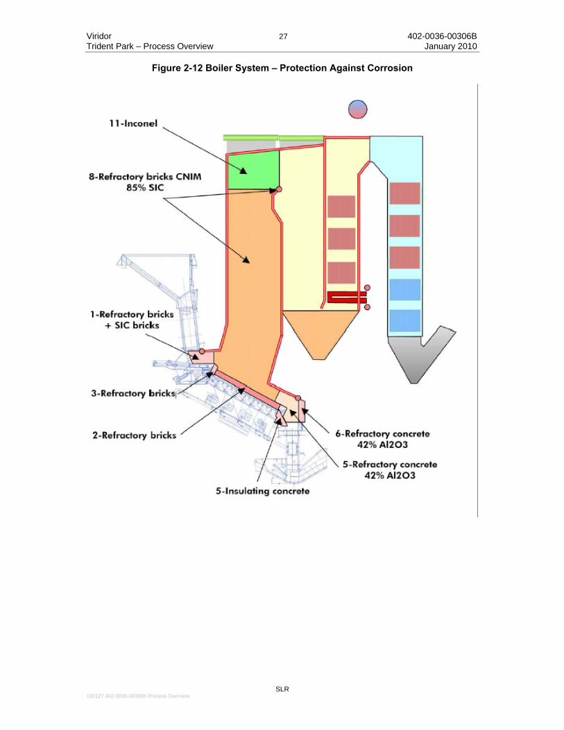
The economiser consists of several banks of plain tubes supported by water-cooled tubes or bars according to flue gas temperature. The economiser is completely drainable and ventable. The economiser is enclosed in a steel welded casing. Protection Against Corrosion
A nickel / chromium superalloy is used in specific areas of high potential risk of corrosion and / or high refractory maintenance. This includes the following areas;
• furnace roof (Side and rear walls, roof); and • upper part of the second pass.

Viridor 26 402-0036-00306B Trident Park – Process Overview January 2010
SLR
100127 402-0036-00306b Process Overview
Note: extended use of Inconel in the furnace (instead of refractory) is restricted by the regulatory condition of T= 850 °C / 2 sec. The proposed design has been determined based on the assumption that the condition T=850°C / 2 sec must be met while incinerating waste at a NCV of 9300 kJ/kg. This assumption is consistent with basic design data and with the CNIM’s obligation to design a plant in compliance with environmental regulations. Any additional extension of the Inconel plated area would change the gas temperature profile in the furnace and would not ensure the above condition is met without auxiliary fuel firing. The mean height of Inconel on the side walls in the upper part of the furnace is one metre.
Refractory
Two kind of refractory are used;
• refractory on casing: refractory bricks, silicon carbide (SiC) bricks, insulating concrete or refractory concrete; and
• refractory on tubes: In these areas CNIM use patented refractory bricks with high SIC contents.
Access Doors, Inspection Holes
Access doors and inspection holes provide access to the convective passes and enable the furnace to be inspected.
Cleaning Equipment
The cleaning system consists of a set of soot blowers for the superheater and evaporator bank. The soot blowing equipment will consist of rotary retractable and semi-retractable multi-jet type soot blowers with motive steam taken from the main High Pressure (HP) steam header.
To ensure satisfactory cleanliness of the economiser tubes, an in-operation vibrating cleaning system is provided for the economiser.
Ash Hoppers
In order to collect the fly ashes under the gas circuits, the boiler is equipped with hoppers.
Fly ash collection hoppers are provided at the bottom of any pass. They are formed from fabricated steel. The hoppers in the high temperature section of the boiler are refractory-lined/water cooled, while the hoppers in the low temperature section of the boiler are of casing type with thermal insulation externally only.
Safety valves
The boiler is fitted with;
• One main safety valve fitted on the drum and sized to release minimum 75 % of the boiler steam rate; and
• One safety valve fitted on the superheater at its outlet and sized for releasing a minimum of one quarter of the boiler steam rate.
This safety valve is set to open before the main safety valves fitted on the drum, to ensure a permanent flow through the superheater.
Viridor 27 402-0036-00306B Trident Park – Process Overview January 2010
SLR
100127 402-0036-00306b Process Overview
Figure 2-12 Boiler System – Protection Against Corrosion

Viridor 28 402-0036-00306B Trident Park – Process Overview January 2010
SLR
100127 402-0036-00306b Process Overview
Steam and Water Piping
The feed water is heated up in the economiser in counter-current flow to the flue gas to a temperature somewhat lower than the evaporation temperature.
From the boiler drum the water flows down through the unheated down-comers and supplier tubes to the lower headers of the evaporator system and thereafter is partly evaporated in the heated evaporator tubes (walls and bundles). The resulting water/steam mixture flows over the riser tubes back to the drum, where the water steam mixture is separated.
The saturated steam from the drum is heated up in the pre-super heater bundles in counter current flow and in the final super heater bundles in co-current flow.
The live steam temperature is kept constant by spray type attemperator located between the 1st and 2nd super heater bundle The attemperator is equipped with variable, orifice type spray valves.
All boiler-heating surfaces (excepted platen type super heaters) can be completely drained and vented.
The system includes one drain and blow-down flash tank. The tank includes a system for disposal of the drain to the recycled water pit.
The different connecting pipes between the blow-down sampling points on the boiler and the flash tank are also supplied.
The temperature at the flash tank outlet can be adjusted, depending on the mean blow-down flow recorded, in order to have a temperature of about 60 °C, i.e. sufficient to send this water to the recirculation or disposal system or use it in the slag discharger. The exact demands regarding temperature will be decided during detailed engineering.
The high pressure, low pressure, steam and feed water pipework will be designed and manufactured in accordance with the relevant national standards or equivalent.
All steam and feed water pipework will be adequately supported with provision for accommodating any expansion encountered by the inclusion of suitable spring supports and expansion joints.
All steam and feed water pipework operating at a high temperature will be insulated.
Flanged joints in the steam and feed water systems will be kept to the minimum number possible.
Turbine isolation (for maintenance purposes) at the exhaust will be through a blind flange. A by pass valve (sized to approximately 10% steam flow) will be provided to allow for functional checking at reduced load prior to returning to normal operation.
Boiler Water Treatment
The boiler feed water is produced by one dual common demineralisation plant.
The treated water will be used to fill up the boilers and water network and then for the make-up of the same.
Each plant is automatically controlled by the levels in the demineralised water tank.

Viridor 29 402-0036-00306B Trident Park – Process Overview January 2010
SLR
100127 402-0036-00306b Process Overview
Demineralised water is stored in a water tank that acts as a buffer tank to ensure continuous availability during normal operation, planned shut-down and/or emptying operations. The storage tank capacity is equal to the volume of 1 boiler.
A combined unit suitable for both phosphate and oxygen scavenger dosing will be fitted. A dosing pump will inject the oxygen scavenger at the feed water pump suction. A dosing pump will inject the phosphate in the drum.
2.3.4 Power Generation Plant and Auxiliaries
General
The ‘Power Generation Plant and Auxiliaries’’ include the following main components;
• steam turbine and auxiliary equipment; • power generator; • air condenser; • condensed steam heater(s); • boiler feed water system; and • miscellaneous equipment.
Steam Turbine and Auxiliary Equipment
The total steam quantity generated by the heat recovery boiler is used in a common condensing / bled turbine to generate electricity. The steam turbine will be used in full condensing mode.
The condensing steam turbo generator is designed for continuous operation. After subtraction of the power required for internal use, the electrical net production will be discharged to the grid system via a step-up transformer.
The selected condensing steam turbo generator will be able to operate in island mode (i.e. completely independently of grid electricity supply) at full steam flow with steam dumped to the condensers at an ambient temperature of up to 30ºC.
Upon loss of the main export connection whilst the turbine generator is running, the turbine output shall automatically reduce in a stable manner to island mode without tripping.
Turbine
The turbine is designed to accept the total steam flow produced by the incineration train under any anticipated ambient conditions.
It will accept the full boiler operating range including operation with all possible combinations of lines in conjunction with acceptable waste within the stoker capability diagram.
A gland steam exhauster system consisting of a condenser and fan exhauster recovers heat and condensate to the feed water system, while non-condensable gases are exhausted to atmosphere outside the building.
Upstream steam pressure is regulated through the turbine by the governor controlled steam admission valves. The governor valves operate sequentially to provide maximum efficiency corresponding to the design rating of the boiler at rated capacity. The governor programmable microprocessor control unit controls the turbine speed and accepts an external control signal generated from the boiler outlet steam pressure and provides all the

Viridor 30 402-0036-00306B Trident Park – Process Overview January 2010
SLR
100127 402-0036-00306b Process Overview
control functions required to maintain safe operation of the turbine. The control unit shall be fully interfaced with the Supervisory Control and Data Acquisition (SCADA) and the boiler control system.
The turbine is protected with a mechanical over-speed trip device and an electronic over-speed unit using speed sensors.
The subsequent loss of oil pressure causes the stop valves to rapidly close and the governing valves to close.
Gearbox
A double helical, horizontally offset, parallel shaft, speed reducing gearbox is provided in between the turbine and the generator.
The gearbox is fitted with the necessary equipment for turbine operation and safety including but not limited to;
• AC motor and manual engagement; • Oil pressure switch interlock; • Bearing temperature indicators and transmitters; and • Bearing vibration sensors. Lubricating oil system
A common remote mounted lube oil system is provided for lubricating the turbine, gearbox and the generator main and subsidiary bearings.
A separate system will supply oil for the high pressure hydraulic operation and servo control of the control and emergency shut off valves.
The main oil pump will be either AC electric motor driven, or driven directly from the low speed gearwheel of the gearbox, and will supply oil to the complete assembly for both lubrication and power control purposes. An AC starting and standby pump is provided to start in the event of failure of the main pump. An AC uninterruptible power supply (UPS) supplied rundown/cooling pump is provided for safe stoppage in case of failure of the main pump.
The emergency AC UPS driven pump which operates on low pressure in the event of both the main pumps being unavailable for maintaining bearing lubrication shall maintain effective cooling for a sufficient length of time, while the unit coasts to a halt and is mechanically or hand driven.
Lubrication oil passes through one of two 100% heat exchangers and a duplex filter for removing particles. A lube oil centrifuge is provided for lube oil conditioning together with fan extraction vented to the outside. The oil tank is fitted with a visible level indicator and high and low level switches. Generator The generator will be supplied with an appropriate excitation cabinet containing; • auto excitation controller for voltage control, power factor; • neutral point cabinet with current transformers, earth resistor with a homopolar
detection core and connection terminals; and

Viridor 31 402-0036-00306B Trident Park – Process Overview January 2010
SLR
100127 402-0036-00306b Process Overview
• monitoring panel containing the following: line voltage meter, excitation ammeter, wattmeter, phase meter, frequency meter, duplex voltage meter, duplex frequency meter, a synchroscope, emergency stop switch, power factor control, voltage and current excitation control, automatic or manual control, control for turbine speed, generator voltage, generator power factor.
Air Condenser
The air condenser is designed to condense a total amount of exhaust steam. The proposed solution is an anti-freezing steam condenser arranged in a direct roof A-frame type, air cooled, mounted on a steel structure. The steam condenser is designed to condense the whole of the steam from the turbine and/or from the by-pass of the turbine. The proposed air-cooled solution allows for maximum flexibility against variations in thermal load and/or ambient condition. Condensate System
Condensate tank:
Condensed steam will be collected and stored in a single condensate tank arranged at ground level. The condensate tank is of a cylindrical shape arranged horizontally and made of carbon steel plates.
Condensate transfer pumps:
Two (2) x 100% condensate pumps are provided to transfer condensate to the de-aerator via condensate heater(s). Pumps are of centrifugal single stage type driven by an AC constant speed electric motor.
Condensed steam heater(s):
Condensed steam heaters are used to improve the Rankine cycle efficiency by heating the condensed steam from the condenser using extraction steam from the turbine. The condensed steam is returned back to the main condensed steam tank.
De-aerator and feed water tank:
Condensate is returned to the de-aerator for suitable heating and de-gasing. The de-aerator tank is sized to insure a storage capacity corresponding to more than 20min. of pump feeding at full load without condensate return.
Feed water pumps:
The boiler is fed with water from the de-aerator by multistage, centrifugal, horizontal feed water pumps. Free thermal expansion takes place in a downward direction.

Viridor 32 402-0036-00306B Trident Park – Process Overview January 2010
SLR
100127 402-0036-00306b Process Overview
2.4 Air Pollution Control Equipment
The proposed Air Pollution Control Equipment will allow the plant to operate at any load within the limits set in the combustion diagram. Emission levels will comply with the European Directive 2000/76/EC dated December 4/2000.
The proposed technology is a combination of the four following processes; • SNCR process into the furnace for Non Catalytic Reduction of NOx; • neutralization of acid gases by injection of hydrated lime in a dry process; • dioxin reduction by injection of activated carbon; and • dust removal through a bag filter.
2.4.1 Basic chemistry of the process
The removal of NOx from the flue gases is performed by SNCR (Selective Non Catalytic Reduction) with urea which is added in the furnace.
The stoichiometric chemical equation for urea (aqueous or anhydrous) reagents:
4NO + 2CO(NH2)2 + O2 = 4N2 + 2CO2 + 4H2O
2NO2 + 2CO(NH2)2 + O2 = 3N2 + 2CO2 + 4H2O
The removal of acidic compounds from the flue gases is performed by chemical reaction with lime which is added and turbulently mixed by way of the reacting duct with its associated residue recycling system.
The main reactions performed in the dry reactor and on the consecutive entrained suspension path are:
Ca(OH)2 + SO2 = CaSO3 + H2O
Ca(OH)2 + SO3 = CaSO4 + H2O
Ca(OH)2 + 2 HCl = CaCl2 + 2 H2O
Ca(OH)2 + 2 HF = CaF2 + 2 H2O
Ca(OH)2 + CO2 = CaCO3 + H2O
Depending on their acid value, the acid polluted gas components react according to the following priority:
SO3 > HF > HCl > SO2 > CO2
Because CO2 is an extremely weak acid, it contributes little towards the overall acidity of the flue gases. Additionally a proportion of CO2 is eventually separated in the form of CaCO3, which is expelled as part of the re-circulation of the absorbents through the stronger acids available in the flue gas.
Concurrently to the described chemical transformation reactions of the acid pollutant gas components with hydrated lime, volatile heavy metals (i.e. mercury) and toxic organic components (i.e. PCDD/F) will also be separated efficiently. In this case, the retention of the
Viridor 33 402-0036-00306B Trident Park – Process Overview January 2010
SLR
100127 402-0036-00306b Process Overview
specified pollutants takes place through adsorption on the carbon-containing surfaces of the activated carbon.
2.4.2 Process description
The proposed in furnace SNCR and dry process pollution control system consists of the following process steps, which the pollutant carrying flue gases pass through consecutively one after the other; • urea is injected upstream in the furnace where NOx reduction takes place; • the dry reacting duct for the intensive and turbulent mixing of pollutant carrying flue
gases, fresh lime absorbent, activated carbon, and recycled residues from the fabric filter;
• the high performance fabric filter for separation of all particle-type pollutants contained in the flue gas flow downstream the reacting duct, mainly composed of entrained fly ash, reaction salts formed from absorbents and pollutants and residually available active absorbent portions;
• the heavy duty recycle system to return most of the fabric filter residues to the suspension reactor, with buffer silo and mechanical conveyors; and
• the induced draft (ID) fan including silencer for compensation of the upstream plant pressure drops, conveying the flue gas flow throughout the plant and controlling the furnace under-pressure simultaneously.
The flue gas from the waste heat boiler passes to the flue gas treatment plant via a coupled flue gas duct.
There, the hot flue gases first pass through to the reaction duct, where they are contacted under highly turbulent conditions with fresh lime, activated carbon, re-circulated and re-activated residues from the bag filter. Such contacts under highly reactive conditions serve to optimise the removal of pollutants and to form dust-like products.
The dust-laden flue gas is then introduced into the bag filter where it is discharged from all particle-type contaminants composed of entrained dust, reaction salts and remaining active reagents. A portion of the dust removed on the fabric filter is returned to the dry reactor after its reactivation.
The flue gas conveying through the plant components including the under-pressure control in the furnace are controlled by the ID fan.
Consumables required are limited to hydrated lime for neutralizing the acid gases, activated carbon to separate volatile heavy metals and toxic organic compounds, and urea for the NOx reduction.
2.4.3 Description of Components and Subsystems
The system described below is a dry system using Urea. It is particularly well suited to medium sized streams. It is proposed to use Urea as to reduce the amount of oxides of nitrogen in the flue gas in order to represent Best Available Techniques as required by the Environmental Permitting regime.

Viridor 34 402-0036-00306B Trident Park – Process Overview January 2010
SLR
100127 402-0036-00306b Process Overview
Functional description:
Urea NOx reduction system
The system will be a dry SNCR process, using urea prills as the reagent. This system has a greater operability than a “wet” system using aqueous urea or ammonia, the reagent is less hazardous, the associated handling systems require less energy, and the many plants in the UK and overseas operating with urear demonstrate a high level of removal efficiency, ensuring compliance with all emission limit standards.
Each furnace has its own air booster to convey the material; a further one is available on stand by for the plant. The installations for all streams are independent and redundant of each other. If one of them is shut down, there must be no effect on the operation of the other one.
The selection of air conveying system and booster is done manually. The stand by booster shall have the same capability as the two others.
The whole installation is controlled from an electrical control and power distribution cabinet, located in an area to be defined during detailed design, with local boxes for each line.
The urea injection metering and injection level selection valve shall be controlled from the plant central control room. The selection of distribution level is generated in the electrical cabinet.
The final choice of injection levels and positions will be made during commissioning and fine tuning on site. Only two levels and two injection points per level will be retained. Consequently the system has been designed to enable easy configuration during the adjustment phase.
Figure 2-13 Schematic for Urea Injection
Viridor 35 402-0036-00306B Trident Park – Process Overview January 2010
SLR
100127 402-0036-00306b Process Overview
Reaction Duct
The reaction duct is used to optimise the mass transfer between the flue gases and the dry absorbents. It is designed as an area of intensive mass transfer. The reactor actively participates in;
• high-performing separation of the pollutants contained in the flue gas under the actual operating conditions of the combustion plant;
• reduction of the generated pollutant peaks by optimal reaction with absorbents; • increase of the operational flexibility; and • considerable minimization of the generated quantity of residues to manage.
High turbulence is produced by the turbulent flow created by carefully calculated flue gas speed.
Its active zone is produced by adding reactivated recycled material coming from the fabric filter, fresh and powdery hydrated lime and activated carbon.
Fabric Filter
The bag filter is used for the major separation of particle pollutants from the flue gas. These pollutants mainly consist of entrained dust, dried reaction salts and used up absorbents.
The bag filter is a high-performing filter with compressed air de-dusting, comprising a chamber-type design with vertically arranged cylindrical bags, the bag bottom, the raw gas inlet duct, the pure gas discharge duct and the dust collection hoppers.
The design of the different chambers consists of a welded gas-proof steel structure with reinforced steel profiles. The welded-in bag bottom separates the raw gas room from the pure gas room. The pyramidal dust collection hoppers are implemented below the raw gas room.
The dust-carrying flue gas is introduced into the bag filter housing through the raw gas duct. The housing is a chamber-type design allowing for the separation, inspection and maintenance of parts of the unit involved in the flue gas process during plant operation thanks to the shut-off valves between the raw gas and pure gas room.
The raw gas related interlock is ensured through shut-off valves between the raw gas duct and the filter chamber and the pure gas related interlock through disk-type or shut-off valves.
The filter bags are arranged inside the filter chambers. The flow runs through the filter bags from outside to inside. During the passage through the filter bags, the dust proportion of the flue gases is retained for a major part and deposited as a filter cake on the surface of the bags. Filter baskets inside the bags prevent the filter bag from collapsing.
The filtered flue gas is directed inside the filter bags and from there to the pure gas chambers and the consecutive pure gas duct.
Main characteristics of the fabric filter; • eight independent cells; • on-line air pulse cleaning of bags; • 100% PTFE media + PTFE membrane bags, with stainless steel (316L) baskets; • eight independent hoppers with high level detection, isolating gate valves, temperature
measurement and connection to the inert gas station;

Viridor 36 402-0036-00306B Trident Park – Process Overview January 2010
SLR
100127 402-0036-00306b Process Overview
• complete by-pass system of underperforming filters; • pre-heating system with booster fan and electrical battery; • pre-coating system using main lime injection circuit: lime is injected during start-up of
the line to protect the bags, as soon as the flue gas flow is sufficient to carry the lime to the filter; and
• downstream dust measurement.
Control logic
In order to limit the increased pressure drop caused by the filter, the filter bags are controlled using differential pressure-control or de-dusted in regular intervals through compressed air pulses. This can be done via manual electronic controls or fully automatically through the short opening of a diaphragm valve, in order to direct the compressed air from the compressed air tank via the nozzles to the relevant filter bag rows. Other relevant process signals, such as flue gas volume flow, current inlet and outlet pollutant concentrations can be considered during the cleaning sequence.
Compressed air pulses from the nozzles are sent inside the filter bags thus generating a pressure wave passing throughout the bag and leading to the short expansion of the filter bag. This phenomenon causes the filter cake to be detached and to fall into the dust collection hoppers, directly arranged under the filter chamber.
From there, the residues are extracted via the feeder screws and transported to the residue silo or re-circulation system.
Recycling of Fabric Filter Residues
The dust like material separated within the fabric filter among reaction salts still contains a certain portion of un-reacted lime. In order to make best use of that, most of the dust coming from the fabric filter is recycled to the reaction duct.
For this purpose, fully-proved mechanical, self-controlled re-circulation equipment developed by CNIM is proposed. The residues are first collected from the dust collection hoppers by means of feeder screws. The extraction is led into the re-circulation buffer silo and material that cannot be accepted is transported to the residue silo automatically.
To make optimum use of the recycled material it is reactivated through maturation prior to re-injection to the reaction duct. For this purpose the buffer silo is sized to allow the correct maturation time for reactivation of the residues.
After being injected to the reactor the recycled material is dragged by the flue gas flow to the fabric filter and will be returned to the reacting duct again.
This type of re-circulation design allows for automatic expulsion of part of the residues from the system corresponding to the sum of fresh absorbents and flue ash taken in, without the need to implement sophisticated and failure-causing control and measurement systems and intermediate tanks. The system further excludes overloads of the reactor/bag filter unit as well as an unnecessarily high absorbent consumption.
Dependable insulation and trace heating and the heavy duty design matching the properties of bulk material ensure the operation of this simple, self-controlled and reliable re-circulation system.

Viridor 37 402-0036-00306B Trident Park – Process Overview January 2010
SLR
100127 402-0036-00306b Process Overview
Dry Injection of Hydrated Lime and Activated Carbon
Hydrated lime and activated carbon are taken from their respective silos using mechanical extraction devices and transported to the feeding point of a common pneumatic conveying pipe by means of speed-controlled feed screws.
A radial fan produces the required volume air-flow and ensures the pneumatic conveying of the absorbent-air mixture to the flue gas duct upstream the dry LAB-Loop reactor. There it is intensively mixed with the flue gases and entrained under continuous reaction with the flue gas pollutants.
Unused portions are recycled to the flue gas flow by way of the recycling and reactivation loop as described above.
ID Fan and Silencer
The ID fan is used for the compensation of plant pressure drops, flue gas conveying throughout the upstream plant components and the depression control in the combustion room.
The fan is a radial speed-controlled fan with bilateral intake and single-flow design. The flue gas enters the welded sheet steel housing via the flue gas ducts on the intake sides, where it is accelerated through the rotor and fed to the discharge end. The rotor is equipped with profile blades and is electro-dynamically balanced out in two levels.
The coupling to up- or downstream flue gas ducts is via compensators. The rotor is located on a shaft with lubricated dust-proof roller bearings and is driven by two three-phase frequency converter controlled motors by means of elastic coupling.
The whole unit is located on a common vibration-free frame housing both the booster fan and the drives.
To minimize the noise emission generated by the equipment of the flue gas treatment plant, an absorptive silencer is connected to the booster fan, which reduces noise emissions at the inlet of the chimney.
Peripheral Equipment
Lime storage
Hydrated lime (Ca(OH)2) is supplied as dry powdered absorbent using bulk delivery trucks and is stored in two bulk material silos. Each silo will have a capacity of approximately 100 m3.
When the minimum level in a lime silo is reached, the operator staff will order the required lime quantity from the supplier.
The lime is fed pneumatically from the delivery truck into the buffer silo. To do so, the extraction coupling of the silo truck is coupled to the coupling of the pneumatic filling pipe of the buffer silo using a flexible hose and fed into the silo by means of the truck compressor dedicated to this purpose.
The feeding operation is accomplished after the full emptying of the silo truck or once the maximum filling level is reached in the silo. The exhaust air generated during the feeding operation is de-dusted by means of a silo top filter and sent to the atmosphere. The exhaust
Viridor 38 402-0036-00306B Trident Park – Process Overview January 2010
SLR
100127 402-0036-00306b Process Overview
air generated during the feeding operation is de-dusted by means of a silo top filter and sent to the atmosphere
From the silo the hydrated lime is discharged for injection in the reaction ducts as described above.
Storage of activated carbon
For the adsorption of the volatile heavy metals (i.e. mercury) and organic components (i.e. PCDD/F), powdered activated carbon (PAC) is added to the flue gas together with lime.
The absorbent is supplied by silo trucks as dry powder and stored in a bulk material silo with a storage capacity of approximately 75 m3. When the minimum level in the silo is reached, the operator staff shall order the required quantity from the supplier.
The PAC is fed pneumatically from the delivery truck into the bulk material silo in a similar manner to the powered lime.
The PAC silo is equipped with a continuous filling level monitoring, a maximum filling level sensor, an overflow sensor, an overpressure and depression safety valve, a mechanical extraction equipment and a silo top filter.
Conveying and storage of APC residues
The APC residues generated in the flue gas treatment plant are a mixture of fly ash carry over from the boiler passes, dried reaction salts (CaCl2 x 2H2O, CaSO4 x 2H2O, CaSO3 x ½H2O, CaF2 x 2H2O, u. a.), used up and fresh absorbents. They are deposited in the dust collection hoppers of the bag filter.
The residues from the fabric filter are conveyed to the buffer silos using mechanical equipment: screw conveyors, chain conveyor and final bucket elevator. In order to avoid operational trouble due to deposits/bonding, the whole equipment for the dust conveying between the extraction from the flue gas relevant plant components and the intake of the residue silo is insulated and equipped with electrical trace heating.
The buffer residue silo is designed as a cylindrical bulk material silo with flat end and is used for the intermediate storage of the generated residues. The silo will have a storage capacity of around 300 m3, and will either feed unused residues back to the reaction duct, or excessive reside to the final storage silos.
2.5 Ash Handling
2.5.1 Bottom Ash
Each incineration train will be equipped with its own ash conveying system. Bottom ash from MARTIN ash dischargers will be conveyed to the ash pit by means of vibrating conveyors and belt conveyor.
Bottom ash is collected from the two ash dischargers by means of a common vibrating conveyor sited at the end of the sorting screen for the coarse fraction. The vibrating screen is designed to allow for a backup ash removal option in case of failure of the main conveying system. In such a case the total ash stream can be diverted temporary storage bins.
The passing fraction of bottom ash is then conveyed directly to the ash storage by a belt conveyor.

Viridor 39 402-0036-00306B Trident Park – Process Overview January 2010
SLR
100127 402-0036-00306b Process Overview
A magnetic separator will allow the split between ferrous and non ferrous bottom ashes. Storage capacity will be designed for a three days storage without operator maintenance and five days with manual stacking.
2.5.2 Fly Ash
Fly ashes will be collected from boiler and economizer hoppers and conveyed to the ash quench.
2.5.3 Flue Gas Treatment Residues
The two FGTR silos are flat-bottomed cylindrical bulk material silos for the intermediate storage of the generated residues. The silos are fully insulated to ensure trouble-free extraction of solid matters.
2.6 SCADA System
The proposed Main Control and Supervision System will consist of a Distributed Digital Control System (DCS) organized on several levels:
Level 0 : Process level
This level ensures logical and analogical signal conditioning: inputs and outputs from and towards local instrumentation and cabinets.
Level 1 : Control level
This level ensures;
• data processing (including logical sequences, closed control loops, mathematic functions) related to the main process;
• data exchanges with local PLC's by communication on serial bus; and • alarms processing.
This level will be composed of;
• Part 1: two number redundant controllers unit; and • Part 2: specific sub-systems.
Level 2 : Supervision level
This level ensures;
• operator interface; • data storage and display; and • alarm processing.
Level 2 enables supervision of the whole plant with detailed information about main process and grouped information for remote and secondary equipment, as well as data storage on short (week) and medium (month) terms ; long term storage is assumed to be made on optical disk or equivalent (via the streamer).
Level 3 : Administrative and technical management level
Level 3 mainly provides the following functions;
Viridor 40 402-0036-00306B Trident Park – Process Overview January 2010
SLR
100127 402-0036-00306b Process Overview
• data analysis; • data long term recording; • data display on screen (tables, trends); • reports printing; and • remote consulting of the operating values.
2.7 Electrical
It is intended to connect the plant to the grid at 33 kV (to be confirmed).
The turbo-generator generates electrical energy at 11 kV and is connected onto the plant 33 kV power distribution system through a 11 kV/33 kV step-up transformer.
The plant auxiliaries are supplied from the 33 kV distribution system through step-down MV/LV transformers with neutral three-phase 50 Hz alternating current.
Should the main line become unavailable together with the turbo-generator set while in normal operation, a stand-by diesel generator will start automatically to enable the power supply to priority circuits allowing for the plant to shut down under full safety conditions.
The diesel generator is not sized to start or operate the plant and shall under no circumstances be used to export electricity, nor to provide electricity, while the main line or the turbo-generator is being used.


