Energy Processing Circuits for Low-Power Applications by Yogesh Kumar Ramadass B.Tech., Indian Institute of Technology, Kharagpur (2004) S.M., Massachusetts Institute of Technology (2006) Submitted to the Department of Electrical Engineering and Computer Science in partial fulfillment of the requirements for the degree of Doctor of Philosophy in Electrical Engineering and Computer Science at the MASSACHUSETTS INSTITUTE OF TECHNOLOGY June 2009 c Massachusetts Institute of Technology 2009. All rights reserved. Author .................................................................... Department of Electrical Engineering and Computer Science May 21, 2009 Certified by ............................................................... Anantha P. Chandrakasan Professor of Electrical Engineering and Computer Science Thesis Supervisor Accepted by ............................................................... Terry P. Orlando Chairman, Departmental Committee on Graduate Students
Transcript
Energy Processing Circuits for Low-Power
Applications
by
Yogesh Kumar Ramadass
B.Tech., Indian Institute of Technology, Kharagpur (2004)
S.M., Massachusetts Institute of Technology (2006)
Submitted to the Department of Electrical Engineering and Computer
Sciencein partial fulfillment of the requirements for the degree of
Doctor of Philosophy in Electrical Engineering and Computer Science
Chairman, Departmental Committee on Graduate Students
2
Energy Processing Circuits for Low-Power Applications
by
Yogesh Kumar Ramadass
Submitted to the Department of Electrical Engineering and Computer Scienceon May 21, 2009, in partial fulfillment of the
requirements for the degree ofDoctor of Philosophy in Electrical Engineering and Computer Science
Abstract
Portable electronics have fueled the rich emergence of new applications including multi-mediahandsets, ubiquitous smart sensors and actuators, and wearable or implantable biomedicaldevices. New ultra-low power circuit techniques are constantly being proposed to furtherimprove the energy efficiency of electronic circuits. A critical part of these energy conscioussystems are the energy processing and power delivery circuits that interface with the energysources and provide conditioned voltage and current levels to the load circuits. These energyprocessing circuits must maintain high efficiency and reduce component count for the finalsolution to be attractive from an energy, size and cost perspective.
The first part of this work focuses on the development of on-chip voltage scalable switchedcapacitor DC-DC converters in digital CMOS processes. The converters are designed todeliver regulated scalable load voltages from 0.3V up to the battery voltage of 1.2V forultra-dynamic voltage scaled systems. The efficiency limiting mechanisms of these on-chipDC-DC converters are analyzed and digital circuit techniques are proposed to tackle theselosses. Measurement results from 3 test-chips implemented in 0.18µm and 65nm CMOSprocesses will be provided. The converters are able to maintain >75% efficiency over awide range of load voltage and power levels while delivering load currents up to 8mA. Anembedded switched capacitor DC-DC converter that acts as the power delivery unit in a65nm subthreshold microcontroller system will be described.
The remainder of the thesis deals with energy management circuits for battery-less sys-tems. Harvesting ambient vibrational, light or thermal energy holds much promise in realiz-ing the goal of a self-powered system. The second part of the thesis identifies problems withcommonly used interface circuits for piezoelectric vibration energy harvesters and proposesa rectifier design that gives more than 4X improvement in output power extracted from thepiezoelectric energy harvester. The rectifier designs are demonstrated with the help of atest-chip built in a 0.35µm CMOS process. The inductor used within the rectifier is sharedefficiently with a multitude of DC-DC converters in the energy harvesting chip leading toa compact, cost-efficient solution. The DC-DC converters designed as part of a completepower management solution achieve efficiencies of greater than 85% even in the micro-watt
3
power levels output by the harvester.The final part of the thesis deals with thermal energy harvesters to extract electrical power
from body heat. Thermal harvesters in body-worn applications output ultra-low voltagesof the order of 10’s of milli-volts. This presents extreme challenges to CMOS circuits thatare powered by the harvester. The final part of the thesis presents a new startup techniquethat allows CMOS circuits to interface directly with and extract power out of thermoelectricgenerators without the need for an external battery, clock or reference generators. Themechanically assisted startup circuit is demonstrated with the help of a test-chip built in a0.35µm CMOS process and can work from as low as 35mV. This enables load circuits likeprocessors and radios to operate directly of the thermoelectric generator without the aid of abattery. A complete power management solution is provided that can extract electrical powerefficiently from the harvester independent of the input voltage conditions. With the helpof closed-loop control techniques, the energy processing circuit is able to maintain efficiencyover a wide range of load voltage and process variations.
Thesis Supervisor: Anantha P. ChandrakasanTitle: Professor of Electrical Engineering and Computer Science
4
Acknowledgments
Firstly, I would like to thank my parents and sister for all the love and support they have
given me over the course of my life. It is the difficult decisions that they have made, that
has brought me to the position I am in right now, and for that I am eternally thankful.
I am extremely grateful to my advisor, Prof. Anantha Chandrakasan, for being more than
a mentor during my stay at MIT and for having taught me lessons which go beyond circuit
design. It was he who encouraged me to work in the power management area despite my
initial unfounded reluctance. The atmosphere he has fostered in his lab is one of collaborative
research and one that is highly motivating to produce great results. I am also thankful to
him for never letting me worry about where the next source of funding is going to come from
and for giving me the freedom to pursue my interests.
My thesis committee members, Prof. David Perreault and Prof. Jeffrey Lang, for having
spent a lot of time with me discussing the work and providing constructive criticism.
Members of Ananthagroup, past and present - too big to list here, for creating the best
workplace to do research. You guys have been excellent and it would be difficult to find a
working group as good as you. And, I am going to miss all the lunch-time discussions of the
past 5 years.
Our administrative assistant, Margaret Flaherty, for doing an enormous lot of behind the
doors work for us and for never ceasing to help you out with any problem. Margaret, I hope
you’ll soon find someone to hang all the pictures of the great people that visit our lab.
Members of MTL administrative and computing staff for the valuable support that they
have provided over the years. Special thanks to Debb, Sam Crooks and Mike Mcllrath.
The coffee crew of Dr. Naveen Verma and Dr. Nigel Drego for all those invaluable
discussions we have had over a cup of caffeine. Many a day, it was part of the reason for me
to come to the lab and I will miss Nige’s 2’o clock knock on the cubicle.
Special thanks to Dr. Denis Daly, with whom I have spent a considerable amount of time
over the past year trying to shape the next step of my career.
Dr. Hanqing Li and Prof. Jeff Lang for having worked closely with me to help build the
5
MEMS switch for the thermal harvester. Nathan Ickes for helping me out with the vibration
harvester testing.
My roommate of 4 years, Saurabh Tejwani, for creating a great environment at home
and for those excellent culinary skills.
Various friends in and around the MIT area, members of all the intramural teams that I
have played in for all the good times.
Chip fabrication and funding provided by National Semiconductor, Texas Instruments,
DARPA, Intel Graduate Fellowship and MOSIS without which this work would not have
been possible. The many members from the industry whom I have had the privilege to
meet being a student of Anantha. Special thanks for Dr. Dennis Buss, Dr. Ian Young, Dr.
Bill Bowhill, Dr. Baher Haroun, Dr. Peter Holloway, Prof. Ayman Fayed for the valuable
knowledge I have gained from you.
My professors at IIT-Kharagpur and all my previous teachers for the valuable wisdom
you have given me. My special thanks to Prof. N. B. Chakrabarti of IIT-Kharagpur for
being a great source of inspiration.
The various sports teams that I am fanatic about, specially Manchester United, Red Sox
and the Patriots for having won so much during my time here at MIT, playing a great part
in speeding up my thesis, and the great city of Boston itself for being a special place to live.
If I have missed anyone of you, please forgive me as true to my spirit, I am still writing
this at 9am when the thesis is due printed and signed at 3pm. So, thanks to the millions
of years of evolution for the adrenaline rush that makes last minute work so much more
exciting.
6
Contents
1 Introduction 21
1.1 Power Delivery in Portable Systems . . . . . . . . . . . . . . . . . . . . . . . 21
1.2 Voltage Scaling and Minimum Energy Operation . . . . . . . . . . . . . . . . 24
3.6 Improvement in bottom-plate parasitic loss with charge recycling . . . . . . . 83
5.1 Component values used in the thermoelectric energy harvester circuit . . . . 176
19
20
Chapter 1
Introduction
Energy efficiency of integrated circuits continues to be a major factor in determining the size,
weight and cost of portable electronic systems. Sophisticated battery operated electronic
systems and self-powered devices have found diverse applications recently. They exist as
autonomous or hand held objects in every environment around us and in some cases even
within us, significantly improving the quality of life and connectivity of users. Specific
applications include portable multi-media handsets, implantable and wearable biomedical
devices, wireless sensor networks, and RFID tags, to name a few. In all of these cases, long-
term battery life/self-powered operation and low cost are paramount. Accordingly, highly
aggressive low-power circuit design and efficient power delivery is required to meet battery
or energy harvesting constraints [4].
1.1 Power Delivery in Portable Systems
The integrated circuit explosion in the last few decades have benefited greatly from tech-
nological advances which follow Moore’s law. The doubling of transistors in a die every
2 years has given rise to smaller, faster, less power hungry transistors which have greatly
enhanced the processing capabilities and features provided by modern portable devices. As
technology scaling has progressed, the nominal core voltage of transistors has dropped from
21
2.5V in a 0.25µm CMOS process to ∼1V in the currently used 45nm CMOS processes. Most
portable electronic systems used today are powered by a battery. The physical limits of
electro-chemistry have prevented battery technologies to advance at the same rapid rate as
the shrinking of transistor sizes or the cramming of more transistors in a given area. Ta-
ble 1.1 gives the typical characteristics of commonly used rechargeable batteries in portable
systems.
Table 1.1: Characteristics of commonly used rechargeable batteries
NiCd NiMH Li-ion Li-ionpolymer
ReusableAlkaline
GravimetricEnergy Density(Wh/kg)
45-80 60-120 110-160 100-130 80(initial)
Volumetric En-ergy Density(Wh/l)
50-150 140-300
270 300 80(initial)
Cycle Life (to80% of initialcapacity)
1500 300-500
500-1000
300-500 50 (to
50%)
Cell Voltage(nominal)
1.25V 1.25V 3.6V 3.6V 1.5V
Owing to its large gravimetric and volumetric densities, Li-ion based batteries are be-
coming increasingly popular for a variety of portable electronic applications like cell phones,
laptops etc. This helps in minimizing the size and weight of the battery. The Li-ion battery
has a nominal voltage of 3.6V. However, during its discharge cycle, the voltage output by
the battery can be widely variant from 4.2V to 2.6V. Figure 1-1 shows the typical discharge
characteristic of a Li-ion battery. Due to the battery voltage being very different from the
nominal voltage of the circuits in a given CMOS technology node and because the bat-
tery voltage varies along its discharge cycle, intermediate DC-DC converters are essential in
portable electronic systems to act as the voltage conversion circuits between the battery on
one side and the load circuits on the other.
Figure 1-2 shows what the inside of a typical cellphone looks like. The complex func-
22
0 500 1000 1500 2000 24003
3.2
3.4
3.6
3.8
4
4.2
Capacity (mAh)
Vol
tage
(V
)
Figure 1-1: Typical discharge characteristics of a Li-ion battery.
tionality within a cellphone is implemented using a variety of different circuits and blocks
each of which is powered using a Li-ion battery. Since the functionalities and operating
methods of the different blocks are usually different, each needs a specific voltage to operate.
For eg. the digital baseband of a cellphone might run at the core voltage for its technology
(say 1V) while certain analog, RF and I/O circuits might require higher voltages to func-
tion properly. This varied splitting of voltage domains requires multiple voltage regulators
to cater to each of the individual blocks. Further, there are certain blocks like the power
amplifier and the core digital baseband processor which consume the majority of the power
within a cellphone. These blocks are supplied by their own individual inductor-based DC-DC
converters to get above 95% efficiency. The intermediate voltages that these inductor-based
DC-DC converters provide is used by other voltage regulators to provide power to the various
other sub-blocks within the cellphone system. Every block cannot have its own dedicated
inductor-based DC-DC converter because of the cost and volume penalities imposed by these
converters. Hence, most of the other voltage regulators are linear regulators (LDO’s) owing
23
to the small on-die size occupied by them. By design, these linear regulators provide very
poor efficiency when their drop-out voltage is large. The initial section of this thesis looks
into the design of switched capacitor DC-DC converters as a more efficient alternative to
linear regulators. Switched capacitor DC-DC converters are switching regulators which make
use of just switches and capacitors to perform voltage conversion. This makes it possible
to implement them on-die reducing the number of off-chip components. The first half of
this thesis talks about switched capacitor DC-DC converters implemented in digital CMOS
processes as high efficiency alternatives to linear regulators.
Baseband(DSP, MCU, Memory)
Display
RFUp/Down/PLL
Audio
LNA
PA
Keypad
LDOBuck
Battery Charger
LDOLDO
LDOBuckLDOLDO
Buck/Boost LED Drivers
Speaker
MIC
Audio Drivers
Figure 1-2: Illustration of different circuit blocks within a cellphone and how they are pow-ered.
1.2 Voltage Scaling and Minimum Energy Operation
In the evolution of modern portable electronic devices, digital data processing is taking an
increasing role and a commensurate fraction of the power consumption. For example, in a
second generation (2G) code division multiple access (CDMA) phone, the digital baseband
24
and the memory circuit take about 10% of the total power that the handset chip set consumes.
While in a third generation (3G) wide band CDMA (WCDMA) phone, this percentage is
30-50% of the overall power consumption, since functions associated with filtering and digital
data streaming are now handled with digital circuitry [5]. Reducing the power consumed
by the digital baseband and memory circuits is of paramount importance to bring down the
overall power consumption of portable electronics and increase battery lifetime.
Supply voltage scaling is one of the most popular methods to reduce power consumption of
integrated circuits. Specifically, in a digital circuit, the active CV 2
DD energy, EACT , required
to complete an operation reduces quadratically with supply voltage. Thus by decreasing the
operating voltage of circuits, their power consumption can be brought down significantly.
However, the decrease in voltage comes at a cost of reduced operating speed. Most digital
circuits do not operate at their highest operating speed all the time. There are large periods
of time when the workload required of them is much smaller.
A video decoding chip is shown as a specific example of the varying workloads of a
digital system and how the system can be operated at different voltages corresponding to
the workload. In video decoding, the frame rate and resolution of the playback video dictates
the performance requirement of the video decoder hardware [1]. Over the past years, the
number of different types of video content has been growing rapidly ranging from professional
cinema to news reports to, most recently, user-generated content. In addition, the numerous
modes of transmission of the video have also expanded from broadcast and playback from
local storage (e.g. DVD), to streaming across the internet and cellular network. Both of
these factors cause the frame rate and resolution of todays video content to vary widely.
Figure 1-3 shows the measured power of a 65nm H.264/AVC video decoder when performing
real-time decoding of video streams of different resolutions.
Dynamic Voltage Scaling (DVS) [6] [7] has become a standard method to minimize power
consumption of digital circuits when their performance requirements vary. As VDD decreases,
transistor drive currents decrease, bringing down the speed of operation of a circuit. A DVS
system adjusts the supply voltage, operating the circuit at just enough voltage to meet
25
0.01 mW
0.1 mW
1 mW
10 mW
100 mW
1 W
0.1 1 10 100
QCIF CIF D1 720p 1080p
Resolution
30fps
Po
we
r
Mpixels/s
15fps
0.70 V
0.85 V
Core Domain
Memory Controller
0.5 V
0.5 V
0.55 V
0.68 V
0.85 V
1.15 V
0.66 V
0.74 V
Figure 1-3: Measured power of a 65nm H.264/AVC video decoder when performing real-timedecoding of video streams of different resolutions [1].
performance, thereby achieving overall savings in total power consumed. While DVS is a
popular method to minimize power consumption in digital circuits given a performance con-
straint, certain emerging applications like wireless micro-sensor networks [8] [9], implantable
medical electronics [10] and RFID systems are severely energy-constrained. Subthreshold
operation [11] [9] [12] of digital circuits, i.e. operating the circuits at a VDD lesser than the
threshold voltage of its devices, is a solution to the energy constrained applications. Though
subthreshold operation makes the circuits operate slower due to the reduced drive currents,
it offers the promise of minimum energy operation. Since, the goal of energy constrained ap-
plications is to minimize the overall energy consumed per operation performed, subthreshold
operation is a viable solution for these applications.
The total energy per operation of a digital circuit can be split into two components :
26
an active energy part and a leakage energy part. The active energy component as is well
known scales down quadratically with VDD as is shown in Figure 1-4 which shows the active
and leakage energy profiles of a 65nm 7-tap FIR filter. The leakage energy component is
due to the leakage power which integrates over the time period of an operation. While it is
negligible at higher voltages, the leakage energy component increases exponentially as VDD
is decreased close to the threshold voltage. These opposing trends of the active and leakage
energy components give rise to a minimum in the total energy consumed per operation. As
in the case shown, this minimum energy voltage occurs below the threshold-voltage for most
practical digital circuits [4] [13].
0.3 0.4 0.5 0.6 0.7 0.8 0.9 1.0 1.1 1.20
0.5
1
1.5
2
2.5
3
3.5
4
VDD
(V)
E/o
p.(N
orm
aliz
ed)
ActiveLeakageTotal
Figure 1-4: Active and leakage energy profiles for an FIR filter in 65nm CMOS. The twoprofiles result in a minimum energy supply voltage of approximately 0.4V.
By introducing the capability of sub-threshold operation, DVS systems can be made to
operate at their minimum energy operating voltage [12] in periods of very little activity,
leading to further savings in total energy consumed. This way ultra-dynamic voltage scaling
(U-DVS) can be achieved. To enable ultra-dynamic voltage scaling systems, it is critical to
27
address the severe challenges faced by low-voltage circuits, particularly as they attempt to
leverage advanced technologies fraught with issues of statistical variation, leakage, and rising
cost. Considerable work has been done in building logic [14] and memory [15] circuits that can
function at low voltages and still have the ability to operate at the maximum voltage at high
speeds. Apart from the digital circuits, a DC-DC converter supplying ultra-low voltages at
high efficiencies is essential to realize the full energy savings that can be achieved by reducing
VDD in a U-DVS system. Most of these systems also comprise of multiple voltage domains
each requiring a distinct voltage. Using traditional switched inductor regulators would mean
using multiple inductors to cater to these different voltage domains. This is prohibitive in
terms of cost and motivates the need to look into an on-chip solution that can provide scaled
supply voltages at good efficiencies. Switched capacitor DC-DC converters is a viable option
for such systems. One of the main drawbacks of traditional on-chip switched capacitor DC-
DC converter is its low efficiency compared to regular inductor-based switching converters.
In this work, the major efficiency limiting losses in an on-chip switched capacitor converter
are addressed and the voltage scalability of the converter is improved. Further, since the
power consumed by ultra-low voltage systems can be of the order of micro-watts, maintaining
the efficiency of the DC-DC converter at these low power levels is a key requirement. Work
done in this thesis addresses this growing need by effective digital control techniques that
enable constant efficiency over a wide range of load current/power levels.
1.3 Self-powered Operation
With the need for portable and lightweight electronic devices on the rise, highly efficient
power generation approaches are a necessity. The dependence on the battery as the only
power source is putting an enormous burden in applications where either due to size, weight or
lifetime constraints, doing away with the battery is the only choice. Emerging applications
like wireless micro-sensor networks [16], implantable medical electronics and tire-pressure
sensor systems [17] are examples of such a class. It is often impractical to operate these sys-
tems on a fixed energy source like a battery owing to the difficulty in replacing the battery.
28
A 1cm3 primary lithium battery has a typical energy storage capacity of 2800J [2]. This
can potentially supply an average electrical load of 100µW for close to a year but is insuf-
ficient for systems where battery replacement is not an easy option. It therefore becomes
necessary to look for alternative sources of energy to power these systems. The ability to
harvest ambient energy through energy scavenging technologies is a practical solution for
battery-less operation. The most common energy harvesters transduce solar, vibrational or
thermal energy into electrical energy. The vibrational harvesters use one of three methods:
chanical energy in the form of vibrations is converted to electrical energy. The thermoelectric
harvesters exploit temperature gradients to generate electrical power. It is also possible to
extract electrical energy from electromagnetic radiation emitted by RF sources. This gener-
ates tens of µWs of usable power and has been used in RFID tags [20] and several implanted
medical devices. However, this method is not energy scavenging in the true sense because
the RF power has to be provided by a dedicated external RF source which is positioned
close to the harvester. Most energy harvesters in practically usable forms can provide an
output power of 10 - 100µW as can be seen from Table 1.2. This sets a constraint on the
average power that can be consumed by the load circuitry for self-powered operation. This
low power output necessitates not only the design of ultra-low power logic circuits but also
efficient power delivery interface circuits that can extract the maximum power available out
of the energy harvesters.
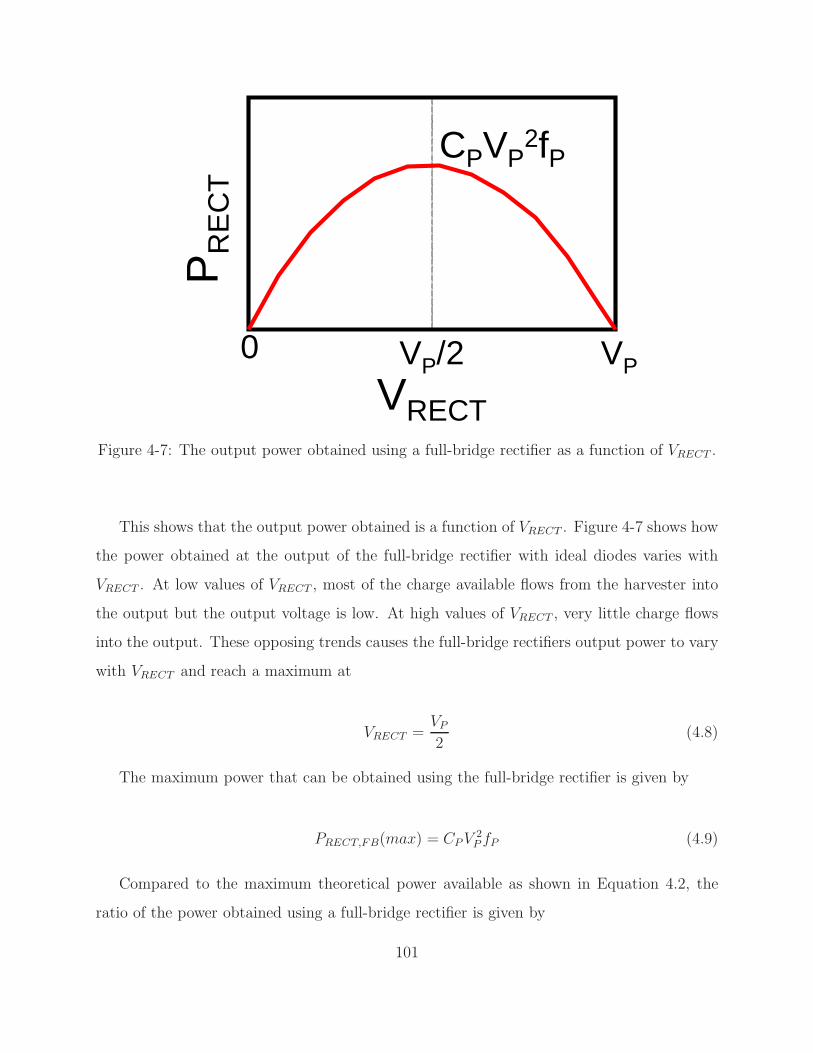
One of the main limitations of existing energy processing circuits that extract power from
energy harvesters is in their interface circuitry. In the specific example of piezoelectric energy
harvesters, the rectifier circuits that interface with the harvester severely limit the electrical
power extractable from the piezoelectric harvesting element. Further, the power consumed
in the control circuits of these energy processors reduces the amount of usable electrical
power. The interface circuits to energy harvesters must be optimized not just for energy
efficiency but also to provide the right impedance to extract the optimum power out of the
energy harvesters. Also, integration of the energy processor electronics onto the same chip
29
Table 1.2: Examples of Energy Harvesting Sources
Source Output Power Comments
Photovoltaic
Guilar [21] 5µW 150µm x 150µm, 20k LUX
Das [22] 120µA/cm2 Protein based, 10W/cm2 excitation
Thermal
Lhermet [23] 4µW/cm2/c 1V at ∆T = 60c
Leonov [24] 250µW Ambient indoor temperature
Stark [25] 24µW 2.7V at ∆T = 5c
Vibrational
Renaud [26] 40µW Piezoelectric, 35mg mass, 1.8kHz
Roundy [27] 335µW Piezoelectric, 2.25ms−2, 60Hz
that also contains the load circuits would be of great benefit in reducing the size and cost
of the overall solution. This thesis looks into the interface circuits specific to piezoelectric
and thermoelectric energy harvesters. For the piezoelectric energy harvesters, new rectifier
designs are developed which are then used within an integrated CMOS power management
solution that enables small form-factor portable applications. In the case of thermoelectric
harvesters, this thesis looks at circuit design techniques that will enable electrical power
extraction from the heat energy output by the human body. This poses new challenges of
operating CMOS circuits from ultra-low voltages (<50mV). Circuit techniques are looked
at to solve this problem and digital control strategies are employed to maximize the power
extracted from the energy harvesting elements.
1.4 Thesis Contributions and Organization
Minimizing the energy consumption of integrated circuits is essential for enhanced battery
life-times and the possibility of self-powered operation. Dynamic voltage scaling (DVS)
[28] is a popular method to achieve energy efficiency in systems that have widely variant
30
performance demands. U-DVS systems require a variable voltage supply that can deliver
subthreshold voltages (∼300mV) at low load power levels (1µW) when idling, and close
to the nominal voltage of the process at high load power levels when performing active
operation. Sub-threshold operation is essential to minimize leakage power in always ON
blocks like SRAM’s and reduce energy/operation of digital circuits that can be turned OFF
after finishing their operations.
As mentioned in Section 1.2, voltage scaling is an extremely attractive technique to
minimize circuit energy. However, the scalable voltages required by the circuits need to be
delivered efficiently from off-chip voltage sources. The ability to do this voltage conversion
completely on-chip is important to reduce the cost and volume of the final solution. The need
for multiple voltage domains further cements this case. The initial part of the thesis deals
with switched capacitor DC-DC converters as viable alternatives to inductor-based switching
regulators for on-chip applications. They can be used to provide load currents in the order
of 10’s of milli-amps with around 80% efficiency. Chapter 2 describes the different efficiency
loss mechanisms within a switched capacitor DC-DC converter with on-chip charge transfer
capacitors. Analytical expressions are provided for these loss mechanisms. The current
handling capability of switched capacitor converters are looked into and insights are given
on how to pick the region of operation of the converter to maximize load current handling
capabilities and efficiency. The analysis done in this chapter is used in the implementation
of CMOS switched capacitor DC-DC converters described in chapter 3.
To demonstrate on-chip voltage scalable DC-DC conversion, three different designs are
implemented in chapter 3. The first design is in a 0.18µm CMOS process and demonstrates a
voltage scalable switched capacitor DC-DC converter that can provide >70% efficiency over
a wide range of load voltages from 0.3V to 1.1V. The converter introduces new techniques
to mitigate some of the common loss mechanisms in a switched capacitor design. With
the help of completely digital control circuitry, the switched capacitor DC-DC converter is
able to maintain high efficiencies over a wide load power range from 5µW to 1mW. The
second design builds on the techniques utilized in the first converter. It is built in a 65nm
31
CMOS process and employs improved gain setting architectures which can handle higher load
currents for the same silicon area. It also employs a charge recycling technique to mitigate
bottom-plate parasitic losses which leads to a 5% improvement in efficiency. Chapter 3
concludes with a switched capacitor DC-DC converter design that is embedded within a
subthreshold microcontroller system. The DC-DC converter acts as the power delivery unit
to the system. It occupies a small fraction of the total area of the system and enables the
microcontroller to operate at subthreshold voltages at >75% efficiency. The analysis and
designs presented in chapter 2 and 3 demonstrate the feasibility of using switched capacitor
DC-DC converters as a high efficiency alternative to linear regulators and as a low cost
alternative to inductor-based switching regulators. Close to 10mA of output current can be
handled by the converters described and even higher current handling capability is possible
with high frequency switching and denser capacitors. Digital control techniques employed
enable the DC-DC converters to maintain a constant efficiency over a wide range of load
voltage and orders of magnitude change in load current.
Extending the battery life-time to over 10 years or eliminating the battery completely is
of prime importance in many sensor-node and medical applications where it is prohibitive
to replace the battery every few years. Harvesting ambient vibrational, light or thermal
energy holds much promise in realizing this goal. Self-powered operation is an exciting area
which is widely researched upon. As discussed in Section 1.3, the interface circuits to energy
harvesters must be optimized not just for energy efficiency but also to provide the right
impedance to extract the optimum power out of the energy harvesters. In the specific case
of piezoelectric energy harvesters, the interface circuit must rectify the AC waveform output
by the harvester and condition it suitably to provide the right voltage to the circuits that
are powered by the harvester. Chapter 4 talks about the commonly used interface circuits
for piezoelectric energy harvesters and identifies the problems with them. Two new rectifier
designs are proposed. The first one enables 2X improvement in output power with the help
of just a CMOS switch. The second rectifier design with the help of an inductor gives more
than 4X improvement in output power extracted from the piezoelectric energy harvester.
32
Chapter 4 demonstrates these rectifier designs with the help of a test-chip built in a 0.35µm
CMOS process. The inductor used within the rectifier is shared efficiently with a multitude
of DC-DC converters in the piezoelectric energy harvesting chip leading to a compact, cost-
efficient solution. The DC-DC converters designed as part of a complete power management
solution achieve efficiencies of greater than 85% even in the micro-watt power levels output
by the harvester.
Chapter 5 deals with thermoelectric energy harvesters. Thermoelectric elements can be
used to harvest thermal energy present in everyday surroundings like on the human body
to provide usable electrical power. The voltage output by the thermoelectric elements are
proportional to the temperature difference across them. This is of concern while using
thermal harvesters in body-worn applications as the voltage output by the harvester is
only 25-50mV in most cases. Chapter 5 talks about some of the commonly used circuits
to startup from ultra-low voltages. A new technique is then presented that allows CMOS
circuits to interface directly with and extract power out of thermoelectric generators. The
mechanically assisted startup circuit demonstrated with the help of a test-chip built in a
0.35µm CMOS process makes use of human motion to generate high voltages which is used
to power load circuits. This enables load circuits like processors and radios to operate
directly of the thermoelectric generator without the aid of a battery. A complete power
management solution is provided that could extract electrical power efficiently from the
harvester independent of the input voltage conditions. With the help of closed-loop control
techniques, the energy processing circuit is able to maintain efficiency over a wide range of
load voltage and process variations. Chapter 6 provides conclusions for the work done as
part of this thesis and suggests open problems for future research related to this work.
33
34
Chapter 2
On-Chip Switched Capacitor DC-DC
Converters
Dynamic Voltage Scaled systems are fast becoming increasingly relevant in modern day power
constrained electronic systems. DVS is one of the most effective techniques to minimize
power consumption while meeting performance requirements. DVS systems usually require
a DC-DC converter that can supply scalable voltages as demanded by the load circuit. These
converters not only have to supply these scalable voltages but also maintain their efficiency
over a wide range. As battery life becomes a key specification, many portable electronic
systems today are designed to consume extremely low amounts of power (<10mW). Even in
more complex electronic systems like cell phones, many power domains within the system
consume less than 10mA of total current. In this space, it becomes feasible to introduce
switched capacitor DC-DC converters as the power delivery units to integrated circuits.
With the help of on-chip capacitors, these DC-DC converters provide higher efficiencies than
possible on-chip with linear regulators while providing the flexibility of scalable load voltages.
DVS systems often require multiple on-chip voltage domains with each domain having specific
power requirements. A switched capacitor (SC) DC-DC converter is a good choice for such
battery operated systems because it can minimize the number of off-chip components or even
eliminate them and does not require any inductors. Switched capacitor DC-DC converters
35
widely referred to in literature as charge pumps have been in use for a long time as voltage
doublers [29] and for generating higher voltages to drive memories and displays [30]. Previous
implementations of SC converters have commonly used off-chip charge-transfer capacitors
[31] [32] to output high load power levels. Some of these converters employ gain hopping
to support a wide range of input voltages [33]. A SC DC-DC converter which integrates
the charge-transfer capacitors was described in [34]. In this chapter, detailed analysis is
provided on the efficiency limiting mechanisms of on-chip voltage scalable switched capacitor
DC-DC converters. This is followed by an analysis on the current handling capabilities of
these converters. The actual implementation of the switched capacitor DC-DC converters is
described in the next chapter.
2.1 DC-DC Converters for U-DVS
2.1.1 Linear Regulators
Low-Dropout (LDO) linear regulators [35] are widely used to supply analog and digital
circuits and feature in several standalone or embedded power management IC’s. The main
advantage of LDO’s is that they can be completely on-chip, occupy very little area and offer
good transient and ripple characteristics, together with being a low-cost solution. Using
LDO’s for U-DVS however is detrimental because of the linear loss of efficiency in an LDO.
A linear regulator essentially controls the resistance of a transistor in order to regulate the
output voltage as shown in Figure 2-1(a). As a result, the current delivered to the load
flows directly from the battery and hence the maximum efficiency achievable is limited to
the ratio of the output voltage to the input voltage (VL/VBAT ). Thus, the farther away the
load voltage is from the battery voltage, the lower the efficiency of the LDO. This hampers
the potential savings in power consumption that can be achieved by lowering the voltage
through dynamic voltage scaling.
36
CL
COMP
VREF
VBAT
VL
(a)
VLLPULSE
WIDTHCONTROL
VBAT
VREF<0:N>
CL
(b)
Figure 2-1: Simplified representation of (a) Low-dropout regulator and (b) Inductor-basedbuck regulator
2.1.2 Inductor based DC-DC Converter
The most efficient DC-DC voltage converters in general are off-chip inductor based switching
regulators, which normally generate a reduced DC voltage level by filtering a pulse-width
modulated (PWM) signal through a simple LC filter as shown in Figure 2-1(b). A buck-type
regulator can generate different DC voltage levels by varying the duty-cycle of the PWM
signal. Given ideal devices and passives, an inductor based DC-DC converter can theoreti-
cally achieve 100% efficiency independent of the load voltage being delivered. Moreover, in
the context of DVS systems, scaling the output voltage can be done with completely digital
control circuitry [36] which consumes very little overhead power. An implementation of an
inductor based switching regulator for voltage conversion is described in Section 4.7. While
buck converters [37] can operate at very high efficiencies (>90%), they generally require
off-chip filter components. This might limit their usefulness for integrated power converter
applications. Integrating the filter inductor on-chip requires very high switching frequencies
(>100MHz) [38] in order to minimize area consumed. This increases the switching losses in
the converter and together with the increase in conduction losses due to the low inductor
Q-factors achievable on-chip, severely affects the efficiency that can be obtained out of the
converter.
37
2.1.3 Switched Capacitor DC-DC Converter
Switched capacitor (SC) DC-DC converters (charge pumps) [29] are widely used in applica-
tions where a voltage higher than, or of the opposite polarity to, the input voltage is needed.
A switched capacitor converter comprises only of capacitors and switches and hence does
not need the magnetic storage elements used by inductor-based buck converters. It employs
these capacitors and switches to perform voltage conversion. U-DVS systems often require
multiple on-chip voltage domains with each domain having specific power requirements. Us-
ing traditional switched inductor regulators would mean using multiple inductors to cater
to these different voltage domains. This is prohibitive in terms of cost and motivates the
designer to look into an on-chip solution that can provide scaled supply voltages at good effi-
ciencies. Switched capacitor DC-DC converters are a viable option for such systems. One of
the main drawbacks of traditional on-chip switched capacitor DC-DC converters is their low
efficiency compared to regular switching converters. The focus of this work is to minimize
efficiency limiting losses of on-chip switched capacitor converters and improve their voltage
scalability.
VLVBAT
CT
Φ1 Φ2
CL
(a)
CL
VL
VBAT
CT
Φ1 Φ2
Φ1
Φ2
Φ2
CT
(b)
Figure 2-2: Switched capacitor DC-DC converter
38
2.2 Scalable Voltage Generation
The fundamental problem with capacitive charge transfer is that a capacitor cannot be
charged from a battery or from another capacitor with 100% efficiency with the help of only
switches. Figure 2-2(a) shows a load capacitor CL being charged from a battery through a
charge transfer capacitor CT . Assuming that CL is held at the voltage VL, in steady state,
let the charge that flows into CT from the battery in phase φ1 be q. This must equal the
charge flowing out of CT into CL in phase φ2. Since the same amount of charge is extracted
from VBAT and flows into VL, the fundamental limit on the efficiency of this circuit can be
given by
Efficiency =Energy delivered to load / cycle
Energy extracted from battery / cycle=
qVL
qVBAT=
VL
VBAT(2.1)
The second scenario shown in Figure 2-2(b) shows a voltage divide-by-2 circuit. Here, 2
capacitors of equal value CT are charged in series in phase φ1 and in phase φ2 they discharge
in parallel to the load capacitor CL. Here again in steady state, the charge transfer capacitors
CT discharge into CL two times the amount of charge they extract from the battery during
phase φ1. Hence, every cycle if q amount of charge is extracted from the battery, 2q amount of
charge flows into CL. Thus, the overall efficiency of this circuit can be given by VL/(VBAT /2).
Thus, we see that in both cases the efficiency of charge transfer is linearly dependent on the
load voltage VL. This can be extended to any topology of a switched capacitor DC-DC
converter all of which are fundamentally limited in efficiency to VL/VNL where VNL is the
no-load voltage of the specific topology. This fundamental limitation in efficiency is because
of conduction losses resulting from capacitive charge transfer using switches. The efficiency
might be further degraded due to the presence of other loss mechanisms which will be
discussed in more detail later in this chapter.
This linear efficiency drop means that in order to get good efficiencies over a wide load
voltage range, more gain settings are needed that have their no-load voltages closer to the
load voltage desired. The first switched capacitor DC-DC converter implemented as part of
39
1.2 1.1 1.0 0.9 0.8 0.7 0.6 0.5 0.4 0.3
1/1
3/42/3
1/21/3
Load Voltage V L (V)
Gai
n S
ettin
g
Figure 2-3: Different gain settings employed to maintain efficiency over a wide load voltagerange.
this work was designed to deliver scalable load voltages from 0.3V to 1.1V from a 1.2V input
voltage source. Figure 2-3 shows how different gain settings can be used to cater to different
load voltages. Consider the case where a load voltage of 550mV is to delivered. Using a 1/1
gain setting, which behaves very much like a linear regulator, limits the efficiency to 45.8%.
Using a 1/2 gain setting increases the theoretical efficiency limit to 91.7%.
CL
VL
VBAT
CT
Φ1 Φ2
Φ1
Φ2
Φ2
CTαCT
Figure 2-4: Implementation of a voltage divide-by-2 circuit which shows the bottom-plateparasitic capacitor.
40
2.3 Primary Loss Mechanisms in a Switched Capacitor
DC-DC Converter
Efficiency of a power converter is a key metric for battery operated electronics and energy
starved systems. The principal contributors to efficiency loss in a switched capacitor DC-DC
converter are listed below. The loss mechanisms will be explained with respect to the voltage-
divide-by-2 circuit shown in Figure 2-4 for easier understanding. They can be extended with
little effort to other topologies of switched capacitor DC-DC converters.
2.3.1 Conduction loss in transferring charge from battery to load
As was described in the previous section, this is a fundamental loss mechanism which arises
from charging a capacitor through a switch. When charge flows from the battery to the load,
some part of it is dissipated within the switches of the DC-DC converter. The farther away
the desired load voltage is from the no-load voltage of a given gain setting, the greater the
dissipation is.
2.3.2 Loss due to bottom-plate parasitic capacitors
The second main contributor to efficiency loss is that due to parasitic bottom-plate ca-
pacitors. This arises due to charging the bottom-plate parasitic capacitance [39] of the
charge-transfer capacitors every cycle. This is of specific concern for on-chip capacitors in
digital CMOS processes. For capacitors implemented using 2 metals, the parasitic arises
due to the capacitance from the bottom-plate to the substrate. For gate-oxide capacitors
implemented with the N-well as the bottom-plate, the parasitic arises due to the reverse
biases diode capacitance of the N-well, P-substrate junction. The bottom-plate capacitance
CBP , scales with the capacitor area and can be expressed as CBP = αC, where α can be as
high as 20% for on-chip capacitors in digital CMOS processes. Consider the circuit shown
in Figure 2-4. During the phase φ1 when the 2 charge-transfer capacitors are charged to
one-half the battery voltage, the bottom-plate parasitic capacitance of the top capacitor
41
also gets charged to VBAT /2. In phase φ2 when these capacitors are connected in parallel
to charge the load, the energy stored in the bottom-plate parasitic capacitance is lost by
connecting it to ground. The energy lost per cycle in steady-state due to CBP of the top
capacitor is
EBP =αCTV 2
BAT
4(2.2)
2.3.3 Gate-drive loss
The power lost due to switching the gate capacitances of the charge-transfer switches is a
significant contributor to the total power loss. The energy expended in switching the gate
capacitances of the charge- transfer switches every cycle can be given by
ESW = CoxWEFFLV 2
BAT (2.3)
where Cox is the gate-oxide capacitance per unit area, WEFF is the cumulative width of
switches that are turned ON / OFF per cycle, and L is the minimum channel length of the
technology node in which the switched capacitor converter is implemented.
2.3.4 Power loss in the control circuitry
The circuit shown in Figure 2-4 will be surrounded with control circuits that are used to
achieve voltage regulation. The power lost in the control circuitry is of specific concern
while delivering ultra-low load power levels. The energy lost in the control circuitry every
switching cycle can be broken into a switching and a leakage component and is given by
ECONT = CCONT V 2
BAT + IleakVBAT TSW (2.4)
where CCONT is the equivalent capacitance switched in the control circuit per cycle,
Ileak is the total leakage current consumed by the control circuitry and TSW is the average
time-period of a switching cycle.
42
The overall efficiency taking into account all the above mentioned losses can be expressed
as the ratio between the total energy delivered to the load per cycle (EL) to the sum of the
energy extracted from the battery (EBAT ) and the energy losses per cycle.
η =EL
EBAT + EBP + ESW + ECONT(2.5)
VL
VBAT
C
Φ1 Φ2
Φ2 Φ1
G1BY2
C
Figure 2-5: Alternate implementation of a voltage divide-by-2 circuit.
2.4 Load Current and Equivalent Resistance Analysis
This section presents an analysis of the current delivered to the load by the switched capacitor
DC-DC converter. Consider an alternate implementation of a voltage divide-by-2 circuit
shown in Figure 2-5. Let it deliver a load voltage VL = VNL – VDIFF , where VNL = VBAT /2,
is the no-load voltage for this gain setting. All the switches are assumed to be sized such
that they have a resistance of RΩ when they are ON. In steady state, let Vc1 and Vc2 be
the voltage across the capacitor C at the end of phase φ1 and φ2 respectively. They can be
represented as
Vc1 = VBAT − VL + [Vc2 − (VBAT − VL)]e−t/τ (2.6)
43
Vc2 = VL + [Vc1 − VL]e−t/τ (2.7)
where τ = 2RC, and t is the time for which the switches are ON in one phase. Assuming
that the time for which the switches are ON in both the phases is the same, t∼1/2fs where
f s is the frequency of operation of the switched capacitor circuit. The voltage swing across
C every half-cycle is given by
Vs = Vc1 − Vc2 =(VBAT − 2VL)(1 − e−1/4fsRC)
(1 + e−1/4fsRC)(2.8)
Let us define the term k as
k =(1 − e−1/4fsRC)
(1 + e−1/4fsRC)(2.9)
Since VL=VBAT /2–VDIFF , Vs can be written as
Vs = 2kVDIFF (2.10)
The current supplied to the load by the voltage divide-by-2 circuit can be given by
IL = 2CVsfs = 4kCVDIFFfs (2.11)
An idealized equivalent circuit of the switched capacitor voltage divide-by-2 circuit is
shown in Figure 2-7. The equivalent circuit does not take into account any of the non-
conduction loss mechanisms and hence is not suitable for efficiency analysis. However, it can
be used to figure out the load current and power delivered by a switched capacitor DC-DC
converter. In the equivalent circuit, REQ represents the equivalent source resistance of a
switched capacitor DC-DC converter. From Equation 2.11, we can define the REQ of the
switched capacitor circuit shown in Figure 2-5 as
REQ =1
4kCfs(2.12)
44
1 10 100 5000
0.2
0.4
0.6
0.8
1
Switching Frequency fs (MHz)
k
(a)
1 10 100 5000
10
20
30
40
50
Switching Frequency fs (MHz)
t / τ
(b)
Figure 2-6: Effect of switching frequency on k and t/τ for C=1nF and R=5Ω
In the limit as f s is increased to ∞, REQ reaches 2R. To understand this intuitively,
it is essential to recognise that in the high frequency limit, the voltage across C does not
change. Hence, it behaves like a voltage source. Also, since the time periods of phase φ1 and
φ2 are equal, the current through C during phase φ1 must be the same as the current out of
it during phase φ2. This forces the voltage across C to be constant at VBAT /2. Hence, the
current to the load during both the phases can be given by VDIFF/2R. This is the same as
having an equivalent resistance of 2R.
45
1/21
VBAT VLREQ
Figure 2-7: Idealized equivalent circuit of a voltage divide-by-2 circuit.
For C=1nF and R=5Ω, the equivalent resistance of the switched capacitor DC-DC con-
verter with change in f s is shown in Figure 2-8. It can be seen from the figure that in
the high frequency limit, REQ reaches 10Ω as expected. This curve is similar to the ones
described in [40], [41] and [42]. The equivalent resistance exhibits asymptotic limits in the
slow and fast switching ends as was discussed in the above references.
1 10 100 5001
10
100
1000
Switching Frequency fs (MHz)
Equ
ival
ent R
esis
tanc
e R
EQ
(Ω
)
Figure 2-8: Equivalent resistance of the switched capacitor voltage divide-by-2 circuit withchange in f s.
With VBAT =1.2V, Figure 2-9 shows the load current output by the switched capacitor
46
DC-DC converter for varying load voltage values. The load current saturates as fs is in-
creased beyond a certain value. Also, the current increases as VL decreases. This is to be
expected from Figure 2-7 where for a given REQ, more current can flow into the output as
VL decreases.
1 10 100 500.1
1
10
Switching Frequency fs (MHz)
Load
Cur
rent
IL (
mA
)
VL = 0.55V
VL = 0.525V
VL = 0.5V
Increasing VL
Figure 2-9: Load current delivered by the switched capacitor voltage divide-by-2 circuit withchange in f s for varying values of VL.
Figure 2-10 shows the load current output by the switched capacitor DC-DC converter
if the switch resistance is varied. VL was set to 0.5V to get these curves. As R decreases,
the load current delivered increases. Also, the knee in the load current curve gets pushed to
higher values of fs with smaller R.
2.5 Efficiency Analysis
The discussion in the above section centered around the equivalent resistance of a switched
capacitor DC-DC converter and the current that it can deliver to the load as its switching
frequency is changed. This section will deal with the efficiency of the switched capacitor
DC-DC converter. It was noted in the above section that increasing fs increases the load
47
1 10 100 500.1
1
10
100
Switching Frequency fs (MHz)
Load
Cur
rent
IL (
mA
)
R = 0.5ΩR = 2ΩR = 5Ω
Increasing R
Figure 2-10: Load current delivered by the switched capacitor voltage divide-by-2 circuitwith change in f s for varying values of the switch resistance R.
current delivered. This section will give insights as to how much can we increase fs before
the efficiency loss becomes significant.
The equivalent resistance in Figure 2-7 takes into account only the conduction losses
within the switched capacitor DC-DC converter. None of the other losses which occur are
accounted for. Section 2.3 talked about the other major sources of loss within a switched
capacitor DC-DC converter. For the converter in Figure 2-5, the gate-switching loss can be
approximated as
PSW = 4CoxWLV 2
DDfs (2.13)
where Cox is the oxide capacitance per unit area, L is the minimum channel length of the
technology and W is the width of the transistor used. The driver stage gate-switching loss is
assumed to be a small fraction of the overall gate-switching loss. There are 4 switches being
turned ON and OFF every cycle and hence the factor 4 in the equation. It is assumed here
that all the switches are identical. This may not be the case since some of the switches in
48
Figure 2-5 that are ground referenced are made of NMOS while the ones referenced to V DD
are made of PMOS. However, it should be easy to incorporate different switches of varying
widths by just summing up their widths into Equation 2.13.
The switches are sized up to achieve a specific resistance across them. Hence, the widths
of the switches can be normalized with respect to the width Wo required to achieve 1Ω
resistance. The power lost due to switching the gates of the transistors can then be expressed
as
PSW = (4CoxWoLV 2
DD)fs
R= Pso
fs
R(2.14)
where Pso is a constant that depends on the gain-setting and technology node being used.
The power lost due to bottom-plate parasitics can be expressed as
PBP = αCV 2
Lfs (2.15)
where α is the fraction of the bottom-plate parasitic capacitance to the actual capacitance
of the capacitor. Taking these losses into account, the overall efficiency of the switched
capacitor circuit shown in Figure 2-5 can be expressed as
η =ILVL
ILVDD/2 + PSW + PBP(2.16)
Plugging in the values from Equation 2.14 and Equation 2.15, the efficiency of the
switched capacitor converter is given by
η =1 − VDIFF
VNL
1 + Pso2kRCVDIFFVDD
+αV 2
L2kVDIFFVDD
(2.17)
The numerator takes into account the conduction losses. The 2nd and 3rd terms in the
denominator take into account the gate-switching and bottom-plate parasitic losses respec-
tively. We can now plot the efficiency of the voltage divide-by-2 circuit of Figure 2-5 assum-
ing C=1nF, R=5Ω, α=0.05 and Pso=7.488x10⁻¹². Figure 2-11 shows the efficiency of the
49
1 10 100 20040
50
60
70
80
90
Switching Frequency fs (MHz)
Effi
cien
cy η
(%
)
VL = 0.55V
VL = 0.525V
VL = 0.5V
Increasing VL
Figure 2-11: Efficiency of the switched capacitor voltage divide-by-2 circuit with change infs for varying values of VL.
switched capacitor converter as fs is varied. If just conduction loss was taken into account,
the efficiency of the converter will have remained constant with change in fs at 91.66% for
VL=0.55V, 87.5% for VL=0.525V and 83.33% for VL=0.5V. The presence of gate-switching
and bottom-plate parasitic losses make efficiency a function of fs. Since VDIFF increases
as VL decreases, the effect of gate-switching and bottom-plate parasitic losses reduce as VL
decreases. This can be seen from the denominator in Equation 2.17. Thus, the efficiency of
the switched capacitor converter is nearly the same for the three different load voltage values
at low fs. As fs increases, the factor k decreases sharply after a certain point (see Figure
2-6(a)). This decrease in k brings down the efficiency of the switched capacitor converter.
Since the gate-switching and bottom-plate parasitic losses are more pronounced at larger VL
values, efficiency drops faster at high VL as can be seen from Figure 2-11.
Figure 2-12 shows the efficiency of the switched capacitor converter with change in the
switch resistance R for VL=0.5V. The efficiency starts higher but begins to drop faster for
higher values of R. Hence, if a large load current needs to be delivered for a given total
capacitance, it is best to use a small R and operate at very high frequencies. Figure 2-
50
1 10 100 50030
40
50
60
70
80
Switching Frequency fs (MHz)
Effi
cien
cy η
(%
)
R = 0.5ΩR = 2ΩR = 5Ω Increasing R
Figure 2-12: Efficiency of the switched capacitor voltage divide-by-2 circuit with change infs as the switch resistance R is varied.
13 shows the efficiency of the switched capacitor converter with change in the factor α
for VL=0.55V. Higher values of α lead to more bottom-plate losses and severely affect the
efficiency.
1 10 100 20020
30
40
50
60
70
80
90
Switching Frequency fs (MHz)
Effi
cien
cy η
(%
)
α = 0.02α = 0.05α = 0.1
Increasing α
Figure 2-13: Efficiency of the switched capacitor voltage divide-by-2 circuit with change inf s for varying values of α.
51
When the load current and efficiency plots of Figure 2-9 and Figure 2-11 are examined
together, it can be observed that operating the DC-DC converter above 30MHz, does not lead
to any significant increase in the load current IL while the efficiency degrades significantly.
Hence, from a practical point of view, it is prudent to operate the DC-DC converter at
30MHz to maximize IL and not lose too much in terms of efficiency. However, this decision
depends on factors such as α, R, VDIFF , Pso and the gain setting in use. A very low value for
α and Pso might lead to the efficiency staying constant for a longer range of fs. In that case,
the frequency of operation of the converter might be pushed higher without losing too much
in efficiency. The decision regarding the frequency of operation (fs)and size of the switches
(R) needs to be made after examining the load current and efficiency curves to figure out
the correct region of operation.
2.6 Summary and Conclusions
Switched capacitor DC-DC converters are a viable option for power delivery in on-chip
integrated circuit applications. They can be used to provide load currents in the order
of 10’s of milli-amps with around 80% efficiency. This chapter has explained the different
efficiency loss mechanisms within a switched capacitor DC-DC converter with on-chip charge
transfer capacitors. Analytical expressions were provided for these loss mechanisms. It was
seen that the bottom-plate parasitic loss is a significant contributor to the overall power
lost within the converter. While the switched capacitor DC-DC converter cannot match the
efficiencies obtained by using off-chip inductor-based DC-DC converters, it can be designed
to maintain an efficiency of close to 80% by using various digitally assisted control techniques.
This efficiency obtained will be better than those obtained using on-chip linear regulators or
inductor-based regulators with CMOS inductors, making the switched capacitor converter an
attractive choice for on-chip power converters. The current handling capability of switched
capacitor converters were looked into and insights were given on how to pick the region of
operation of the converter to maximize load current handling capabilities and efficiency. From
the analysis provided, it was seen that increasing the switching frequency of the converter
52
above a certain value does not lead to a proportional increase in output current handling
capability. The analysis done in this chapter will be used in the implementation of CMOS
switched capacitor DC-DC converters to be described in the next chapter.
53
54
Chapter 3
CMOS Implementation of Switched
Capacitor DC-DC Converters
The previous chapter provided analysis on the efficiency and load current handling capa-
bilities of switched capacitor DC-DC converters. It was shown that with on-chip charge
transfer capacitors, the converters can achieve high efficiencies of around 80% while supply-
ing load currents of up to 10mA. The analysis will be transformed into practical designs
in this chapter where three different implementations of on-chip switched capacitor DC-DC
converters will be described. The first implementation is in a 0.18µm CMOS process and
it presents techniques to achieve scalable load voltages with an efficiency which stays al-
most constant. New techniques are presented to mitigate bottom-plate parasitic, switching
and control losses. The second implementation is in a 65nm digital CMOS process and it
builds on the techniques developed in the first prototype. The second design also provides
newer designs for gain settings and a charge recycling approach to mitigate bottom-plate
parasitics. The third design is of an embedded switched capacitor DC-DC converter in a
subthreshold microcontroller digital IC. It is a smaller version of the second design and
demonstrates the application of switched capacitor DC-DC converters as embedded power
supplies in integrated circuits.
55
3.1 A Voltage Scalable Switched Capacitor DC-DC Con-
verter
This section explains the implementation of a switched capacitor DC-DC converter with
on-chip charge transfer capacitors that can deliver a continuous voltage supply quantized to
10mV. The key specifications for the DC-DC converter are listed here.
• CMOS Technology Node = 180nm
• Battery Voltage (VBAT ) = 1.2V
• Load Voltage Deliverable (VL) = 0.3V to 1.15V
• Load Power = 1µW to 1mW
The targeted application for the DC-DC converter is an ultra-dynamic voltage scaled
system consuming a peak power of 1mW at its high voltage end and microwatts in the low
subthreshold voltage end. It was shown in Section 2 that multiple gain settings are needed
in a switched capacitor DC-DC converter to maintain constant efficiency over a wide range
of load voltages. This section describes how scalable load voltages are generated from a
1.2V off-chip battery. Consider the G1BY2 gain setting in Figure 3-1. The charge-transfer
capacitors are equal in value and help in transferring charge from the battery to the load.
Switches with φ1 marked on them turn ON when φ1 goes high and charge the charge-transfer
capacitors from the battery (VBAT ). In the other phase of the clock switches marked φ2 turn
ON, and the charge-transfer capacitors dump the charge gained onto the load capacitor
(VL). At no load, the G1BY2 gain setting circuit tries to maintain the output voltage VL at
VBAT /2 (0.6V), where VBAT is the battery voltage. The actual value of VL that the circuit
settles down to is dependent on the load current IL, the switching frequency and CB. The
equations for energy extracted per cycle and the power delivered to the load are presented
in Section 3.3. Figure 3-1 shows the different gain settings that were employed in the SC
DC-DC converter. The output load voltage is scalable between 0.3V to 1.15V. Each gain
56
setting is clocked by two non-overlapping phases φ1 and φ2 of a system clock. In the first
phase φ1, the on-chip charge-transfer capacitors are charged from the battery. In φ2, this
charge gained is passed on to the load.
VLVBAT
12CB
Φ1 Φ2
G1BY1
VBAT
4CB
Φ1 Φ2
4CBΦ2
Φ2
Φ1
VL
4CB
Φ1
G2BY3
Φ2
Φ1
VBAT
3CB
Φ1 Φ2
3CBΦ2
Φ2
Φ1
VL
3CB
Φ1
G3BY4
Φ2
Φ1
Φ23CB
Φ1Φ
1
VBAT
4CB
Φ1 Φ2
4CB
Φ2
Φ2
Φ1
VL
4CB
Φ2
Φ1
G1BY3
Φ2
CL
VL
IL
VBAT
6CB
Φ1 Φ2
6CB
Φ1
Φ2
Φ2
G1BY2
Figure 3-1: Gain settings used to generate efficiently a wide range of load voltages from a1.2V supply.
The G1BY1 gain setting provides 1.2V at no-load. This gain setting behaves essentially
like a linear regulator and it is used to provide load voltages between 0.9V and 1.2V. The
G1BY2 gain setting with a no-load voltage of 0.6V is a simple voltage divide-by-2 circuit,
where 2 capacitors of equal value 6CB are charged in series and discharge to the load in
57
parallel. This gain setting caters to load voltages between 0.4V and 0.6V. The G1BY3 gain
setting is a divide-by-3 circuit and it caters to load voltages of 0.4V and below. Here 3
capacitors of equal value are charged in series in one phase and discharge to the load in
parallel in the other phase.
VBAT
3CB
9CB
3CB3CB
3CB
3CB
VL
G3BY4
VBAT
4CB
8CB
4CB4CB
4CB
VL
G2BY3
Φ1 Φ2
Figure 3-2: Arrangements of capacitors during phases φ1 and φ2 in the G3BY4 and G2BY3gain settings.
The G2BY3 gain setting has a no-load voltage of 0.8V and it provides a 2/3rd voltage ratio
output. Its functioning can be explained by looking at the configuration of its capacitors
during phases φ1 and φ2 as shown in Figure 3-2. In G2BY3, during φ1, two capacitors
of value 4CB and 8CB are charged in series from the battery. In steady state with low
bottom-plate parasitics and assuming the switches are designed to allow the capacitors to
settle, the top capacitor of value 4CB gets charged to 800mV or 2/3rd of the battery voltage
and the bottom capacitor of 8CB to 400mV or 1/3rd of the battery voltage. During φ2,
the top 4CB capacitor is connected directly to the load while the bottom 8CB capacitor is
split into two and connected in series with the load. This way the total voltage across the
58
series combination is 800mV. The G2BY3 gain setting is used to deliver load voltages below
800mV. The G3BY4 gain setting is a ratio 3/4 circuit and has a no-load voltage of 0.9V. Its
operation is similar to the G3BY4 gain setting. But here, during φ1, a series combination of
3CB and 9CB gets charged from the battery. In phase φ2, the 9CB capacitor is broken down
into three 3CB capacitors that are connected in series to charge the load. The G3BY4 gain
setting is used to deliver load voltages below 0.9V.
3CB 3CB 3CB
CB CB CB
1/1 1/1, 1/2
3/4, 1/23/4, 1/2
1/1, 2/3, 1/3
1/1, 2/3, 1/3
1/1, 2/3, 1/2, 1/3
abc
d
Figure 3-3: Topology switches used to piece together capacitor fragments for a given gainsetting.
All the gain settings employ the same amount of charge transfer capacitance of 12CB.
The ability to split a given amount of capacitance into multiple parts to achieve different
gain settings is possible on-chip. Doing the same thing with off-chip capacitors might involve
multiple discrete capacitors which will raise the board area occupied by the converter. The
capacitor fragments are joined together with the help of topology switches as shown in Figure
3-3. A topology switch represented by a two-headed arrow joins two capacitors. It consists
of 2 switches, one to connect the top plates and one for the bottom plates. The topology
switch is turned ON when the gain setting marked on top of the arrow is employed.
Apart from the topology switches, charge-transfer switches are employed within each gain
setting. These switches are driven by either φ1 or φ2. All the charge-transfer switches used in
59
−4CB4CB4CBG1BY3
−6CB−6CBG1BY2
−4CB4CB4CBG2BY3
3CB3CB3CB3CBG3BY4
−−−12CBG1BY1
XBOTMIDTOP
−4CB4CB4CBG1BY3
−6CB−6CBG1BY2
−4CB4CB4CBG2BY3
3CB3CB3CB3CBG3BY4
−−−12CBG1BY1
XBOTMIDTOP
TOP
MID
BOT
X
VBAT
GND
GND
GND
ALL
−−
ALL
3/4, 2/3, 1/3
−
3/4, 2/31/3
−
1/2, 1/32/3
Φ1
Φ2
1/2, 1/3−
3/4, 2/3, 1/2, 1/3−
−3/4
2/3, 1/3−
3/4−
a
b
c
d
3/4, 2/3
−3/4
3/4−
VL
VL
VL
Figure 3-4: Charge-transfer switch array (each box represents a switch).
the individual gain settings are realized from a total of only 13 switches as can be seen from
the switch array in Figure 3-4. Each box in the array is representative of a switch which is
turned ON depending on the gain setting in use and the phase of the clock. For instance, the
switch which connects the top plate of capacitor TOP to the battery is turned ON in phase
φ1 for all gain settings while the switch that connects the bottom plate of capacitor MID to
ground (GND) turns ON during φ1 for gain settings G3BY4, G2BY3 and during φ2 for gain
setting G1BY3. The table inside Figure 3-4 shows the value of the individual capacitors
used in the different topologies. The nodes marked a, b, c and d correspond to the similarly
named nodes shown in the topology switches of Figure 3-3. The charge-transfer switches
are realized using PMOS or NMOS transistors or a combination of them depending on the
location of the switch in the array (see Section 3.4.3). A very simple digital control scheme is
utilized to turn ON the switches depending on the gain setting in use. This arrangement of
the switch array enables efficient sharing of charge-transfer switches between multiple gain
60
settings.
CLK
COMP CL
VLVL
AUTOMATIC FREQUENCY
SCALER
EN_W2
SWITCH MATRIX
NON-OV CLKGEN
VB
AT
(1.2
V)
12
G<0
:4>
IL1/32/3÷
EN_W4VL
VREF2
CLK4XCLK
DACVREF
V1p
8
Figure 3-5: Architecture of the switched capacitor DC-DC converter system.
3.2 Switched Capacitor DC-DC Converter System Ar-
chitecture
Figure 3-5 shows the architecture of the SC DC-DC converter. At the core of the system is
the switch matrix which contains the charge-transfer capacitors, and the topology, charge-
transfer switches as shown in Figure 3-1. A suitable gain setting is chosen depending on the
reference voltage VREF , which is set digitally. The digital reference is converted to an analog
value using an on-chip charge redistribution digital-to-analog converter. The entire circuit
except for the topology switches operates out of a 1.2V voltage supply. A 1.8V supply is
used only for the topology switches. In steady state, as there is no switching involved in the
topology switches, negligible power is consumed from the 1.8V supply. A pulse frequency
modulation (PFM) mode control is used to regulate the output voltage to the desired value.
A dynamic comparator clocked by the signal CLK is used for this purpose. When the
61
output voltage VL is above VREF , the switches are all set to the φ1 mode. When VL falls
below VREF , the comparator triggers a φ2 pulse, which charges up the output load capacitor.
The non-overlapping clock generator block prevents any overlap between the φ1 and φ2 ON
phases. A clock divider is used to generate φ1/3 and φ2/3 phases. The use of these phases is
explained in Section 3.4.2.
3.2.1 Automatic Frequency Scaler
To minimize gate-switching losses, the circuit automatically adjusts the switching frequency
depending on the load power demand. The automatic frequency scaling (AFS) block which
performs the frequency selection is shown in Figure 3-6. An additional comparator called
the overload comparator is used in the AFS block. The reference voltage of the overload
comparator is set to VREF−VOFF , where VOFF is an offset voltage (∼20mV) which again is set
digitally. When the DC-DC converter, operating in steady state, cannot supply the desired
load power at a given switching frequency, VL begins to fall below VREF (see Equation 3.3).
As VL falls below VREF−VOFF , the overload comparator triggers the INCR signal. This
signal is used to double the switching frequency which in turn doubles the width of the
charge-transfer switches. The charge-transfer switches are sized such that the capacitors
just settle to their final voltage at the end of the clock phases. Hence, on doubling the
switching frequency, the switch sizes are also doubled. At low load powers, the switching
frequency is brought down with the help of a counter mechanism. If the number of φ2 pulses
for every 4 CLK cycles is found to be less than 3, the CLR W4 signal is triggered which
halves the switching frequency and the width of the charge-transfer switches. The signals
EN W2 and EN W4 determine the switching frequency. When EN W2 is high, 2X the
minimum clock frequency is used and when EN W4 is high, 4X the minimum clock frequency
is used. The signals EN W2 and EN W4 are fed into the switch matrix to suitably size
the charge-transfer switches. While the PFM mode control effectively reduces the frequency
of φ2 pulses as load power decreases, the AFS block helps in bringing down the overall
system switching frequency together with the width of the charge-transfer switches, thereby
62
reducing the switching losses in the gate-drive and the control circuitry. The entire control
circuitry is digital and consumes no static power, which is a critical feature to achieve good
efficiency at ultra-low load power levels. It is extremely scalable in terms of complexity to
suit the load power and voltage demands of the target application.
÷ 2 ÷ 2
EN
_W2
Q
QSET
CLR
D
CLR
_W2
EN_W2
CLK
COMP
VL
DACVREF – VOFF
Q
QSET
CLR
D
CLR
_W4
EN_W4
0
1
EN
_W4
0
1
CLK4X
CLK
Q
QSET
CLR
D
COUNTER
CLR
VBAT
2
< 3?
EN_W4
CLR_W2CLR_W4
RESET
4TH CLK CYCLE
INCREASE FREQUENCY
DECREASE FREQUENCY
CLK_MUX
INCR
Figure 3-6: Automatic frequency scaling Block.
3.3 Power Delivery
This section presents an analysis of the power delivered to the load by the DC-DC converter.
Consider the G1BY2 gain setting shown in Figure 3-1. Let the G1BY2 gain setting deliver
63
a load voltage VL = VNL – VDIFF , where VNL = VBAT /2, is the no-load voltage for this
gain setting. The switches are designed to let the capacitors just settle during phase φ1 or
φ2. This presents a good trade-off between the frequency of operation, switch size, output
current handling capability and overall efficiency as was seen from the analysis presented in
chapter 2. While operating in steady-state, during phase φ2, both the 6CB charge-transfer
capacitors discharge down to VL when the load capacitor is much larger than 6CB. When
they are connected back in series again during phase φ1, both these capacitors get charged
back to VBAT /2. The energy extracted from the battery during this process is given by
EBAT = 6CBVBAT VDIFF (3.1)
During φ2, this excess charge is transferred to the load capacitor. The charge-transfer
capacitors transfer twice the charge gained from the battery during φ1. However, this charge
is delivered at a voltage VL and hence, as was explained before, the energy delivered to the
load every cycle is a linear scaled version of the energy extracted from the battery and is
given by
EL = EBATVNL − VDIFF
VNL= 12CBVLVDIFF (3.2)
The maximum power that can be delivered to the load by this gain setting when switching
at a frequency fs is then given by
PL = ELfs = 12CBVLVDIFFfs = EBAT fsηlin (3.3)
where ηlin is the linear efficiency loss. From this expression it can be seen that for a
given load voltage to deliver more load power, CB or fs need to be increased. Increasing CB
increases the energy extracted from the battery every switching cycle, whereas increasing fs
increases the rate of delivery of the charge packets. The power delivered to the load also
depends on the gain setting being used. Table 3.1 gives a breakdown of EBAT and ηlin for
the various gain settings.
64
Table 3.1: Energy extracted from battery every cycle
Gain Setting EBAT ηlin
G1BY1 12CBVBAT VDIFF VL/1.2V
G3BY4 3CBVBAT VDIFF VL/0.9V
G2BY3 4CBVBAT VDIFF VL/0.8V
G1BY2 6CBVBAT VDIFF VL/0.6V
G1BY3 4CBVBAT VDIFF VL/0.4V
It can also be noted that the larger VDIFF is, i.e. the farther VL is from the no-load
voltage, the more power that the converter can deliver. This again is due to increased
EBAT . Thus, if a given gain setting is unable to meet the load power requirement even at
the highest switching frequency, the next higher gain setting is used. This is the reason
that even at moderate load power levels of 100µW, the G2BY3 gain setting delivers a load
voltage of 590mV and not the G1BY2 gain setting from a 1.2V battery. This leads to a drop
in efficiency than that could have otherwise been achieved had the load power requirement
been low.
3.4 Techniques to Increase Efficiency
A variety of techniques were employed to increase the efficiency of the switched capacitor
DC-DC converter. These are classified here based on the key source of loss they target.
3.4.1 Reducing Conduction Loss
To minimize conduction loss, different gain settings (Figure 3-1) are switched in, to reduce
the difference between the no-load voltage (VNL) of a gain setting and VL. Assuming that a
65
load voltage less than 600mV is being supplied by the G2BY3 gain setting, conduction loss
imposes a limit on the maximum efficiency that can be achieved to ηmax = VL / 0.8. By
switching to the G1BY2 gain setting, this efficiency limit can be improved to ηmax = VL /
0.6.
3.4.2 Reducing Loss due to Bottom-plate Parasitic Capacitors
The energy lost per cycle in steady-state due to CBP of the top capacitor in the G1BY2 gain
setting is
EBP = 1.5αCBV 2
BAT (3.4)
while the energy extracted from the battery per cycle is given by
EBAT = 6CBVBAT VDIFF (3.5)
Let the ratio of EBP to EBAT be given by the following equation:
EBP
EBAT= KP
VBAT
VDIFF= 0.25α
VBAT
VDIFF(3.6)
For normal switching, the factor KP is 0.25α. The factor 0.25 in KP is a gain setting-
dependent parameter (Table 3.2) while α is a technology-dependent parameter which depends
on process parameters and the type of capacitor being used.
Divide-by-3 Switching
A divide-by-3 switching scheme was used to address the problem of bottom-plate parasitic
capacitors. In the G1BY2 gain setting shown in Figure 3-7, both the top and bottom
charge-transfer capacitors contribute to energy delivery to the load. However, only the
top charge-transfer capacitor contributes to bottom-plate loss. So, in order to reduce the
percentage losses due to bottom-plate parasitics, the top charge-transfer capacitor in the
G1BY2 gain setting is not allowed to get involved in energy transfer to the load every
66
VBAT
3CB
Φ1 Φ2
3CB
Φ2/3
Φ1
VL
3CBΦ
1/3
G3BY4
Φ2
Φ1/3
Φ2/33CB
Φ1/3
Φ1/3
VBAT
4CB
Φ1 Φ2/3
4CB
Φ2
Φ2
Φ1
VL
4CB
Φ2
Φ1
G1BY3
Φ2/3 VBAT
6CB
Φ1
6CB
Φ1
Φ2/3
Φ2
G1BY2
Φ2/3
Φ2/3
VL
Figure 3-7: Divide-by-3 switching applied to three different gain settings.
cycle. Instead, it is only connected to the load once every few cycles. This way an overall
improvement in efficiency is achieved. In the divide-by-3 switching scheme, for every gain
setting, the capacitance that leads to significant bottom-plate parasitic loss is identified and
it is switched to the load only once every 3 clock cycles. This way, the fraction of the energy
lost due to bottom-plate parasitics is decreased. For the G1BY2 gain setting as shown in
Figure 3-7, the top capacitor 6CB is switched on to the load only once every 3 cycles. The
energy extracted from the battery over 3 cycles is
while the energy lost due to CBP remains the same as given by Equation 3.4. Thus, there
is a 1.75X improvement in KP when divide-by-3 switching is employed. For the G1BY3
gain setting, the top capacitor contributes the most to bottom-plate loss and is switched
only once in 3 charge transfer cycles. Since no marked improvement was observed in the
G2BY3 gain setting, the divide-by-3 switching scheme was not employed. For the G3BY4
gain setting, the bottom capacitors are switched once in every 3 cycles. This is different from
the other gain settings because in G3BY4 gain setting, the top capacitor contributes 3/4th
to the energy transfer per cycle but the bottom capacitors contribute more to the parasitic
67
loss. Thus by switching the bottom capacitors once in 3 cycles, a significant fraction of
the energy can still be transferred per cycle while reducing the bottom-plate parasitic loss.
While divide-by-3 switching improves efficiency by reducing the contribution of bottom-plate
losses, it requires a higher switching frequency for a given load power level due to decreased
energy transfer per cycle. While this increases gate switching losses in gain settings G1BY3
and G1BY2, the divide-by-3 switching scheme decreases switching losses in G3BY4 because
of the reduction in the number of switches being switched every cycle (see Table 3.3). The
improvements obtained in KP can be seen from Table 3.2.
Table 3.2: Improvement in KP by Divide-by-3 Switching
Gain Setting KP KP,div−by−3
G1BY1 0 n/a
G3BY4 0.375α 0.216α
G2BY3 0.222α n/a
G1BY2 0.25α 0.141α
G1BY3 0.555α 0.368α
Section 3.6.2 shows a different method of attacking bottom-plate parasitics which makes
use of an inductor. The expected improvement in efficiency due to using divide-by-3 switch-
ing is shown in Figure 3-8 when an α=0.05 is considered. The improvement in efficiency
is large when VDIFF is small because this is the region where the bottom-plate parasitics
significantly affect the efficiency. As VDIFF increases, the effect of bottom-plate losses go
down and hence, the improvement in efficiency due to divide-by-3 switching is also minimal.
3.4.3 Reducing Gate-drive Loss
The energy expended in switching the gate capacitances of the charge- transfer switches
every cycle can be given by
ESW = nCoxWLV 2
BAT (3.8)
68
0.3 0.4 0.5 0.6 0.7 0.8 0.9 1.0 1.155
60
65
70
75
80
85
90
95
Load Voltage (V)
Effi
cien
cy (
%)
normal switchingdiv−by−3 switching
Figure 3-8: Expected improvement in efficiency due to divide-by-3 switching.
where n is the number of switches used and it is dependent on the gain setting, Cox
is the gate-oxide capacitance per unit area, W and L are the width and length of the
charge-transfer switches. The width of each switch is however proportional to the total
charge-transfer capacitance and the frequency of switching. ESW can then be expressed as
ESW = nβCBfsV2
BAT (3.9)
where the constant β depends on Cox, L, the mobility µ and the threshold voltage of the
devices. The ratio of ESW to EB can be expressed by Equation 3.10. Here again n is a gain
setting dependent parameter while β is technology dependent.
ESW
EB
= KsfsVBAT
VDIFF
= nβfsVBAT
VDIFF
(3.10)
To minimize the gate-switching loss, depending on the location of the charge-transfer
switch and the gain setting in use, either only a PMOS or an NMOS switch is used instead
of a transmission gate comprising both PMOS and NMOS devices. The automatic frequency
scaling technique described in Section 3.2.1 scales the width of the charge-transfer switches
69
as the switching frequency changes. This way, if the load power decreases by half, the AFS
block halves both the switching frequency and the width of the charge-transfer switches,
thereby effectively halving the ratio of ESW to EBAT .
3.4.4 Reducing Power Loss in the Control Circuitry
The power lost in the control circuitry is of specific concern while delivering ultra-low load
power levels. The energy lost in the control circuitry every switching cycle can be broken
into a switching and a leakage component and is given by
ECONT = KcV2
BAT + IleakVBAT TSW (3.11)
where Ileak is the total leakage current consumed by the control circuitry and TSW is the
average time-period of a switching cycle. The control circuitry employed does not consume
any static power other than the subthreshold leakage currents in the digital circuitry. This
is a critical feature in this application. Further, the AFS block scales the switching loss in
the control circuitry with load power by suitably adjusting the switching frequency.
The overall efficiency taking into account all the above mentioned losses can be expressed
as the ratio between the total energy delivered to the load per cycle to the sum of the energy
extracted from the battery and the energy losses/cycle.
η =EL
EBAT + EBP + ESW + ECONT
=
(
1 − VDIFF
VNL
)
(
1
1 + KpVBAT
VDIF F+ Ksfs
VBAT
VDIF F+ Kc
VBAT
CBVDIF F+ IleakTSW
CBVDIF F
)
(3.12)
On dividing the numerator and denominator by EBAT , the overall efficiency can be ex-
pressed in a more compact form where the pre-factor is due to the linear efficiency loss due
to conduction. The 2nd term in the denominator is due to the bottom plate parasitic loss.
The next term is due to gate-drive switching loss, and the 4th and 5th terms are due to
70
switching and leakage loss in the control circuitry. We see that while the linear conduction
loss increases as VDIFF increases, the other losses decrease with VDIFF . Thus, for any given
gain setting there is an optimum VDIFF where the efficiency is maximized. The contribution
of the switching losses in the control circuitry and the gate-drive can be minimized by in-
creasing CB. The leakage loss however is independent of CB for a given load power because
as CB increases, the switching period TSW also increases. In ultra-low load power levels, this
leakage power component can be significant as the last term in the efficiency equation is just
a ratio of the leakage power to load power.
3CB
CB
Switches
Control
Figure 3-9: Die photo of the switched capacitor DC-DC Converter.
3.5 Measurement Results
A switched capacitor DC-DC converter test-chip, incorporating all the features explained
in the sections above, was fabricated in National Semiconductor’s 0.18µm CMOS process.
71
Figure 3-9 shows a die-photo of the implemented chip. The chip occupies a die area of 1.6
x 1.6mm2 with the active circuitry consuming just 0.57mm2, bulk of which was occupied by
the charge-transfer capacitors. Gate-oxide capacitors were used for charge-transfer because
of their high density and low bottom-plate parasitics. A total of 2.4nF of charge-transfer
capacitance was used. The maximum clock frequency (CLK 4X in Figure 3-6) employed
was 15MHz. The DC-DC converter was able to deliver load voltages from 300mV to 1.1V.
The efficiency of the SC converter with change in load voltage while delivering 100µW
to the load from a 1.2V supply is shown in Figure 3-10(a). The converter was able to
achieve >70% efficiency over a wide range of load voltages. The increase in efficiency of
close of 5% due to the divide-by-3 switching scheme can be seen at voltages catered to by
the gain settings G3BY4, G1BY2 and G1BY3. The measured efficiency plot closely matches
the simulated efficiency values as obtained by using Equation 3.12 with an α=0.05. The
topology switch into the G3BY4, G2BY3, G1BY2 and G1BY3 gain settings was made at
850mV, 750mV, 570mV and 350mV respectively, when divide-by-3 switching was employed.
When normal switching was employed, the switch into G3BY4 was made at 825mV. The
switching between gain settings does not occur at the no-load voltages of the individual gain
settings. This is because at very low VDIFF ’s the efficiency is low due to the bottom-plate
and switching losses. The optimum load voltage where efficiency is maximized for each gain
setting can also be seen from the peaks in Figure 3-10b. The reason for this was explained in
the previous section. The efficiency of the SC converter with change in load power is shown
in Figure 3-10(b). The G1BY1 gain setting was used to deliver 1V and G1BY2 gain setting
was used to deliver 0.5V. At 0.5V, the DC-DC converter was able to achieve close to 74%
efficiency over a wide range of load powers. The effect of switching losses in bringing down
the efficiency can be seen at load power levels above 150µW.
Table 3.3 shows a breakdown of the power lost in the different loss mechanisms while
delivering 100µW at 0.8V through the G3BY4 gain setting. A quantitative estimate of the
reduction in bottom-plate losses due to divide-by-3 switching can be seen.
Figure 3-11 shows a measured plot of the transient in load voltage when the reference
72
(a)
(b)
Figure 3-10: (a) Efficiency plot with change in load voltage (b) Efficiency plot with changein load power
voltage is raised from 0.3V (G1BY3) to 1V (G1BY1). The SC DC-DC converter takes
close to 6µs to raise the output voltage to 1V when 100µA is being delivered to the load.
The waveforms corresponding to the EN W4 and INCR signals show the operation of the
automatic frequency scaling block explained in Section 3.2.1. The EN W4 signal remains
73
Table 3.3: Breakdown of the different loss mechanisms while delivering 100µW at 0.8V(ηnormal = 0.717, ηdivby3 = 0.763)
Loss Mechanism Power Loss
Normal Div-by-3
Conduction 12.45µW 12.45µW
Bottom-plate 14.68µW 7.47µW
Gate-drive 8.32µW 6.38µW
Control 4µW 4.69µW
VL
INCR
EN_W4
Figure 3-11: Transient response of the switched capacitor DC-DC converter as the loadvoltage is changed.
high till the desired load voltage is reached, thereby enabling a fast transient response. Once,
the converter settles close to 1V, the EN W4 signal goes low to reduce the switching losses.
74
3.6 Switched Capacitor DC-DC Converter with Im-
proved Gain Settings and Charge Recycling
The previous implementation demonstrated the feasibility of using switched capacitor DC-
DC converters as on-chip power supplies offering high efficiencies. However, the converter
could handle load currents of only up to 1mA. The ability to handle higher load currents
is very valuable for switched capacitor DC-DC converters. This expands the application
scope of the converter, enabling it to be the power delivery source for a variety of low
to medium power circuits. This section deals with the design of a 65nm CMOS 10mA
switched capacitor DC-DC converter that improves upon the concepts developed in the
previous implementation. This implementation introduces newer gain setting architectures
that enable higher load current handling ability together with reduced bottom-plate losses.
Also, issues related to bottom-plate parasitics are dealt with differently in this design using
charge recycling approaches.
CL
VL
IL
VBAT
6CB
Φ1 Φ2
6CB
Φ1
Φ2
Φ2CL
VL
IL
VBAT
12CB
Φ1 Φ2
Φ2 Φ1
G1BY2_v2G1BY2_v1
Figure 3-12: The G1BY2 gain setting implementation of version 1 and 2 of the switchedcapacitor DC-DC converter.
75
3.6.1 Improved Gain Settings
One of the limitations of the switched capacitor DC-DC converter described in Section 3.1 is
the low amount of output currents it can handle. The current handling capability is limited
by the arrangement of the capacitors within the gain settings. The gain settings described in
Section 3.1 were of the indirect kind in that there was no direct transfer of charge from the
battery to the load during any of the phases. The charge transfer was isolated by charging the
charge-transfer capacitors from the battery during phase φ1 and letting those intermediate
capacitors charge the output load capacitor during phase φ2.
Consider the G1BY2 gain setting of version 1 of the switched capacitor DC-DC converter
in Figure 3-12. The charge-transfer capacitors are equal in value and get charged from the
battery during φ1. The charge these capacitors gained in phase φ1 is delivered to the load
in phase φ2. Two capacitors of equal value are required to get a 1BY2 gain setting. The
circuit on the right of Figure 3-12 shows the newer implementation of the 1BY2 gain setting.
Here, the load capacitor itself is used as part of the charge transfer process during φ1. This
has two main advantages. Firstly, it helps in transferring charge to the output capacitor
during both phases of the clock. Next, the two separate charge-transfer capacitors needed in
the first implementation can be clubbed into one bigger capacitor thereby extracting more
charge from the battery every cycle.
These advantages can be expressed quantitatively as follows. From Equation 3.3, it was
shown that the G1BY2 gain setting of the first implementation could handle a maximum cur-
rent of 12CBVDIFFfs while supplying a load voltage of VL = VBAT /2− VDIFF and switching
at a frequency fs. For the G1BY2 setting in version 2, during phase φ2, the 12CB charge-
transfer capacitor discharges down to VL. During φ1 when the charge-transfer capacitor is
connected in series with the load capacitor, the charge-transfer capacitor gets charged to
VBAT /2 + VDIFF . The energy extracted from the battery during this process is given by
EBAT = 24CBVBAT VDIFF (3.13)
The charge obtained from the battery in φ1 also flows into the load capacitor. During
76
φ2, this excess charge which went into the charge-transfer capacitor is transferred to the
load capacitor. Thus the load capacitor gets twice the charge extracted from the battery.
However, this charge is delivered at a voltage VL and hence, the energy delivered to the load
every cycle is a linear scaled version of the energy extracted from the battery and is given
by
EL = EBATVNL − VDIFF
VNL
= 48CBVLVDIFF (3.14)
The maximum current that can be delivered to the load by this gain setting when switch-
ing at a frequency fs is then given by
IL = 48CBVDIFFfs (3.15)
This is 4 times the current handling capability of the G1BY2 gain setting in the first
version. Thus, a significant improvement in current handling capability can be obtained by
efficient ordering of the charge-transfer and load capacitors. The added benefit of the new
arrangement is the reduced effect of bottom-plate losses. This can be intuitively understood
by seeing that the new G1BY2 setting delivers 4 times as much charge per cycle as the old
version but only increases the bottom-plate losses by 2 times every cycle. Thus on the whole
the effect of the bottom-plate losses decrease by 2 times. This can be obtained quantitatively
as follows:
The energy lost per cycle in steady-state due to the bottom-plate capacitance CBP of the
charge-transfer capacitor in the G1BY2 gain setting is
EBP = 3αCBV 2
BAT (3.16)
while the energy extracted from the battery per cycle is given by Equation 3.13. Thus
the term KP defined in Section 3.4.2 for the new G1BY2 setting is 0.125α. This is half of
the value obtained by the old G1BY2 setting, which confirms the reduction in the effect
of bottom-plate losses by a factor of 2. The basic difference in this design is to utilize
77
VBAT
6CB
Φ1 Φ2
6CB
Φ1
Φ2
Φ2
VBAT
12CB
Φ1 Φ2
Φ2 Φ1
VBAT
6CB
Φ1 Φ2
6CB
Φ2 Φ1
Φ1
VLΦ2
Φ2
VLVBAT
12CB
Φ1 Φ2
VL
VL
11
12
1(1+1)
=
12
13
1(1+2)
=
Figure 3-13: Examples to show how new gain settings are obtained by rearranging switchesof the gain settings in the first implementation.
the load capacitor in the charge-transfer process. This reduces the stack of charge-transfer
capacitors needed to achieve a particular gain setting and also helps in delivering more
charge per cycle to the load capacitor. If a particular gain setting in the previous version
gave out a voltage ratio of p/q, then by connecting the ground terminal of the bottom-most
charge-transfer capacitor during phase φ1 to the load terminal, a gain setting with a voltage
ratio of p/(p + q) can be obtained. This is illustrated with examples in Figure 3-13. The
circuit at the top shows how the G1BY1 setting is transformed into the G1BY2 setting
in the new implementation by connecting the bottom-plate of the 12CB capacitor to the
load during φ1. Similarly, by connecting the bottom-plate of the lower 6CB capacitor to
the load during φ1, the old G1BY2 setting can be transformed to the new G1BY3 setting.
The various gain settings employed in this design are shown in Figure 3-14. The G1BY1
gain setting is the same as the old version. The G3BY4 gain setting is obtained by doing a
p/q to p/(p + q) transformation on an older G3BY1 gain setting. The G2BY3 gain setting
78
is obtained by doing a transformation on an older G2BY1 gain setting. Two new gain
settings are introduced in this version. The G3BY5 and G2BY5 gain settings are obtained
by doing the transformation on older G3BY2 and G2BY3 gain settings respectively. These
gain settings were not used in the older version because the capacitive stack would have been
too large to achieve them. This would have significantly increased the bottom-plate losses
while lowering the current handling capability. The G2BY5 gain setting gives a 0.48V output
at no-load and the G3BY5 gain setting provides 0.72V at no-load. All the gain settings are
2-way interleaved in this implementation to reduce the input current and output voltage
ripple.
VLVBAT
12CB
Φ1 Φ2
G1BY1
VBAT
6CB
Φ1 Φ2
Φ1
VBAT
6CB
Φ1
Φ2 Φ1
Φ2
VL
G2BY3
VBAT
6CB
Φ1 Φ2
6CB
Φ2 Φ1
Φ1
VLΦ2
Φ2
G1BY3
VBAT
4CB
Φ1 Φ2
Φ1
VBAT
4CB
Φ1
Φ1
Φ2
VL
VBAT
4CB
Φ1
Φ2 Φ1
Φ2
G3BY4
CL
VL
IL
VBAT
12CB
Φ1 Φ2
Φ2 Φ1
G1BY2
VBAT
4CB
Φ1 Φ2
Φ2
4CB
Φ1
Φ1 VL
4CB
Φ1
Φ2 Φ1
Φ2
G2BY5
Φ2
VBAT
4CB
Φ1 Φ2
Φ2
4CB
Φ1
Φ1 VL
4CB
Φ2
Φ2 Φ1
Φ2
G3BY5
VBAT Φ1
Figure 3-14: Gain settings used in the second implementation to generate efficiently a widerange of load voltages from a 1.2V supply.
79
Table 3.4: Energy extracted from battery every cycle for the 2 versions of gain-settings
Gain Setting EBAT (ver. 1) EBAT (ver. 2) Improvement
G1BY1 12CBVBAT VDIFF 12CBVBAT VDIFF same
G3BY4 3CBVBAT VDIFF 16CBVBAT VDIFF 5.33X
G2BY3 4CBVBAT VDIFF 18CBVBAT VDIFF 4.5X
G3BY5 n/a 10CBVBAT VDIFF n/a
G1BY2 6CBVBAT VDIFF 24CBVBAT VDIFF 4X
G2BY5 n/a 6.66CBVBAT VDIFF n/a
G1BY3 4CBVBAT VDIFF 9CBVBAT VDIFF 2.25X
The improvement in energy extracted from the battery and thereby the output load
current handling capability of the newer gain settings is shown in Table 3.4. It can be seen
that greater than 4X the current handling capability can be attained with the newer version
for most of the gain settings. On top of this, the newer gain settings offer improvement in
the bottom-plate parasitic loss for some of the gain settings as shown in Table 3.5.
Table 3.5: Improvement in bottom-plate parasitic loss
Gain Setting KP (ver. 1) KP (ver. 2) Improvement
G1BY1 0 0 same
G3BY4 0.375α 0.281α 1.33X
G2BY3 0.222α 0.222α same
G3BY5 n/a 0.32α n/a
G1BY2 0.25α 0.125α 2X
G2BY5 n/a 0.36α n/a
G1BY3 0.555α 0.37α 1.5X
80
ΦCR
CBPLCR
VBAT
6CB
Φ2 Φ1
Φ1 Φ2
G1BY2
VL
VBAT
6CB
Φ1 Φ2
Φ2 Φ1
VL
CBP
Figure 3-15: Charge Recycling used to recover the energy stored in the bottom-plate parasiticcapacitor.
3.6.2 Charge Recycling
The problem of efficiency loss due to bottom-plate parasitics was described in Section 2.3.2.
The first implementation of the switched capacitor DC-DC converter in 0.18µm CMOS used
divide-by-3 switching (Section 3.4.2) to reduce the effect of bottom-plate parasitics on ef-
ficiency. While this technique could provide an improvement in efficiency, it leads to a
reduction in the current handling capability. A different approach is used in this implemen-
tation to tackle the problem due to bottom-plate parasitics. The bottom-plate loss arose
because the charge stored in it was dumped to ground when the clock phase transitioned. In
this implementation, the energy stored in some of the bottom-plate parasitic capacitors is
recycled to the equivalent capacitor in another interleaved bank before it is lost to ground.
Figure 3-15 shows the implementation of the charge recycling circuit. The G1BY2 setting
is shown in the figure. The figure shows two interleaved banks of the gain setting each
working out of phase. During the φ1 phase, the bottom-plate parasitic capacitor CBP of
the right bank gets charged to the load voltage. Normally, this energy is lost when the
circuit transitions to the φ2 phase. In the period between when φ1 turns OFF and phase
φ2 turns ON, the charge recycling (CR) switch is turned ON using the pulse φCR. This
helps in transferring the charge across CBP of one bank to the bottom-plate parasitic of the
81
other interleaved bank with the help of an on-chip bondwire inductor LCR. The amount of
energy transferred depends on the resistance along the recycling path. Assuming that the
voltage across the bottom-plate capacitor is VL for one bank, the voltage obtained at the
bottom-plate capacitor of the other bank after charge recycling can be given by
0.3 0.4 0.5 0.6 0.7 0.8 0.9 1 1.155
60
65
70
75
80
85
90
95
VL (V)
Effi
cien
cy (
%)
ver. 2, no CR
ver.2, with CR
ver. 1
Figure 3-16: Comparison of the simulated efficiency curves of the second version of theswitched capacitor DC-DC converter with the measured efficiency of the first version.
V (afterCR) =VL
2+
VL
2e
−πβω (3.17)
where β = R/2LCR, ω =√
ω2o − β2 and ωo = 1/
√
LCRCBP /2. Here, R is the resistance
along the recycling path. This has to be minimized for effective recycling. The derivation
of the above equation is provided in Appendix A. The charge-recycling switch needs to be
turned ON for just enough time to achieve zero-current switching of the inductor current.
Once charge recycling has taken place, only the remaining charge has to be provided to the
bottom-plate capacitor to bring it up to VL. This reduces the efficiency loss due to bottom-
82
plate parasitics. A similar approach is taken in the other gain settings, where the capacitor
which leads to the most bottom-plate loss is identified and is charge shared using the same
inductor with the corresponding capacitor of the interleaved bank. Figure 3-16 shows the
improvement in efficiency obtained by using charge recycling with the help of an on-chip
bondwire inductor of size 1nH. The simulated efficiency obtained is much better than the
measured efficiency obtained by the first implementation with divide-by-3 switching. While
the inductor based charge recycling approach holds much promise, the quality factor of the
bondwire inductors obtained on-chip for this implementation was not as high as expected.
Hence, the improvement attained did not match up with simulated values. In the presence of
low quality inductors, the final voltage obtained after charge recycling on the bottom-plate
capacitor is effectively VL/2 as can be seen from Equation 3.17. This can be obtained with
the help of just the charge recycling switch without the inductor. In the case where just the
switch is used, the improvement in KP obtained is shown in Table 3.6.
Table 3.6: Improvement in bottom-plate parasitic loss with charge recycling
Gain Setting KP (ver. 2, noCR)
KP (ver. 2,with CR)
Improvement
G1BY1 0 0 same
G3BY4 0.281α 0.211α 1.33X
G2BY3 0.222α 0.148α 1.5X
G3BY5 0.32α 0.32α 1.33X
G1BY2 0.125α 0.0625α 2X
G2BY5 0.36α 0.252α 1.43X
G1BY3 0.37α 0.222α 1.67X
3.7 Measurement Results
The second version of the switched capacitor DC-DC converter was implemented in Texas
Instruments’ 65nm CMOS process. Figure 3-17 shows a die photo of the implemented chip.
83
Figure 3-17: Die photo of the second version of the switched capacitor DC-DC Converter.
The chip occupies a die area of 1mm x 1mm with the active circuitry consuming just 0.52mm2,
bulk of which was occupied by the charge-transfer capacitors. Gate-oxide capacitors were
used for charge-transfer because of their high density and low bottom-plate parasitics. A
total of 3nF of charge-transfer capacitance was used. The die photo of the chip also shows
the bondwire inductor connected between the pads on the die.
The efficiency of the SC converter with change in load voltage while delivering 500µA
to the load from a 1.2V supply is shown in Figure 3-18. The converter was able to achieve
>75% efficiency over a wide range of load voltages. The increase in efficiency due to the
charge recycling scheme can be seen. The switch-only charge recycling scheme was used for
measurements due to the poor quality inductors obtained on-chip. The measured efficiency
plot closely matches the simulated efficiency values as obtained by using Equation 3.12 with
α=0.05. The addition of 2 new gain settings helps prevent the efficiency from going below
75% at around 0.6V and below 65% at around 0.4V. The efficiency of the SC converter with
change in load current while delivering 0.5V to the output using a G1BY2 gain setting is
shown in Figure 3-19. The DC-DC converter was able to achieve greater than 75% efficiency
84
0.3 0.4 0.5 0.6 0.7 0.8 0.9 1.0 1.1 1.255
60
65
70
75
80
85
90
95
VL (V)
Effi
cien
cy (
%)
ver. 2 − no CRver. 2 − with CRver. 1
Figure 3-18: Efficiency plot with change in load voltage with IL=500µA. The efficiency plotfor version 1 switched capacitor converter was obtained with IL=100µA.
over a wide range of load currents. The newer gain setting architecture enables this converter
to support a load current of up to 8mA while keeping the overall area occupied the same.
This is a significant improvement over the previous version. The fundamental efficiency
limit due to conduction losses at this load voltage is 83.3%. The bottom-plate parasitic
losses reduce the efficiency achieved by 3% over the load current range. The efficiency at the
higher load current regions is further brought down by switching losses while below 10µA,
the control losses bring down the efficiency.
The second implementation of the switched capacitor DC-DC converter was able to pro-
vide more than 4X the current handling capability of the previous version for the same area
occupied. This was achieved by modifying the gain settings architecture. A new approach
was taken to tackle bottom-plate parasitics in this implementation. The approach involved
the use of an on-chip inductor to effectively recycle the bottom-plate charge. While this
method is beneficial when high quality inductors are available on-chip, in the absence of
85
3 10 100 1000 800060
65
70
75
80
85
IL (µA)
Effi
cie
ncy
(%)
Effi
cien
cy (
%)
Load Current (µA)
LimitBottom-plate
Switching Loss
Control Loss
83.3%
Figure 3-19: Efficiency plot with change in load current at VL = 0.5V.
it, a switch-only scheme can provide moderate recycling benefits as can be seen from the
improvement in efficiency in Figure 3-18. Also, in the second version, the addition of newer
gain settings helped in keeping the efficiency nearly constant over the wide load voltage range
of 0.3V to 1.15V.
CLK
COMP CL
VL
VREF
enW<0:2>
SWITCH MATRIX
NON-OV CLK GENERATOR
VB
AT
(1.2
V)
Φ1
Φ2
G<0
:4>
IL
Figure 3-20: Architecture of the embedded ultra-low-power switched capacitor DC-DC con-verter.
86
3.8 Ultra-Low-Power Switched Capacitor DC-DC Con-
verter for an MSP430 Microcontroller
The previous sections have described standalone switched capacitor DC-DC converters which
could provide scalable load voltages at high efficiencies. This section describes the imple-
mentation of an embedded DC-DC converter which functions as the power delivery unit in a
subthreshold MSP430 microcontroller system [14]. The microcontroller is designed to oper-
ate in the subthreshold region where substantial energy savings can be achieved by reducing
the VDD of digital and memory circuits. A DC-DC converter supplying ultra-low voltages
at high efficiencies is essential to realize the full energy savings that can be achieved by re-
ducing VDD in a subthreshold system. Since, the power consumption of the logic and SRAM
load circuits drop exponentially at subthreshold voltages, the DC-DC converter was designed
to deliver a maximum of 500µW of load power. This reduced load power demand makes
switched capacitor DC-DC conversion an ideal choice for this application. The switched-
capacitor (SC) DC-DC converter is based on the design described in the previous section,
and makes us of 600pF of total on-chip charge transfer (flying) capacitance to provide scal-
able load voltages from 0.3V to 1.1V. The logic and SRAM circuits however, utilize voltages
only up to 0.6V.
Figure 3-20 shows the architecture of the DC-DC converter. The converter uses an all-
digital Pulse Frequency Modulation (PFM) mode of control to regulate the output voltage.
In this method of control, the converter stays idle till the load voltage VL falls below the
reference voltage (VREF ), at which point a clocked comparator enables the switch matrix to
transfer one charge packet to the load. A PFM mode control is crucial to achieving high
efficiency for the extremely low power system being built. The switch matrix block contains
the charge transfer switches and the charge transfer capacitors.
One of the main efficiency limiting mechanisms in a switched capacitor DC-DC converter
is the linear conduction loss [43]. To maintain efficiency over the wide load voltage range
of 0.3V to 1.1V, this converter employs five different gain settings (G<0:4>). Figure 3-21
87
CL
VL
IL
VBAT
12CB
Φ1 Φ2
Φ2 Φ1
VBAT
6CB
Φ1 Φ2
Φ1
VBAT
6CB
Φ1
Φ2 Φ1
Φ2
VL
VBAT
6CB
Φ1 Φ2
6CB
Φ2 Φ1
Φ1
VLΦ2
Φ2
VBAT
4CB
Φ1 Φ2
Φ1
VBAT
4CB
Φ1
Φ1
Φ2
VL
VBAT
4CB
Φ1
Φ2 Φ1
Φ2
G1BY2
G2BY3 G1BY3 G3BY4
VLVBAT
12CB
Φ1 Φ2
G1BY1
enW<0>
enW<1>
enW<2>
1X
2X
4X
1
1X
Figure 3-21: The different gain settings used within the switch matrix. A simplified repre-sentation of the switch size control is shown in the inset.
shows how the different gain settings are achieved from a total charge transfer capacitance of
12CB (600pF). The external voltage input to the system is 1.2V. Each gain setting at no-load
provides a voltage ratioed output of the input voltage. A suitable gain setting (G<0:4>) is
chosen depending on the proximity of its no-load voltage to the load voltage being delivered
and its ability to provide the load power demand [43]. Since, the logic and SRAM load
circuits utilize voltages only up to 0.6V, in the actual testing of the chip, only gain modes
G2BY3, G1BY2 and G1BY3 were used.
The switching losses in the converter are dominated by the energy expended in turning
the charge transfer switches ON and OFF. The switch widths are designed such that the
charge transfer capacitors just settle at the end of a charge transfer cycle. In order to scale
switching losses with load power, the charge transfer switches have adjustable widths which
are enabled by the signal enW<0:2> as shown in the inset in Figure 3-21. Any decrease
(increase) in the load power by a factor of 2, halves (doubles) the clock frequency (CLK)
of the comparator and correspondingly the width of the charge transfer switches is also
88
2.29mm
128Kb SRAM array
DC-DC converter
Core logic (2 power domains)
1.86
mm
Figure 3-22: Die Photo of the MSP430 microcontroller chip showing the embedded switchedcapacitor DC-DC converter.
halved (doubled). This helps to decrease the switching power by 4X when the load power
decreases by 2X leading to an increase in efficiency at lower load power levels. [43] describes
a method to automatically determine the signal enW<0:2> as the load power varies. The
gain in efficiency as the load power decreases close to 320µW and 160µW in Figure 3-23
is due to the scalable switch width design. However, at very low load power levels (sub-
5µW), leakage and other fixed losses in the control circuitry bring down the efficiency of the
switched capacitor DC-DC converter.
The MSP430 microcontroller system together with the embedded DC-DC converter was
implemented in a 65nm CMOS process. The DC-DC converter, including charge transfer
capacitors, occupies just 0.12mm2. It is a small fraction of the overall area occupied by the
chip as shown in Figure 3-22. The minimum energy point of the microcontroller occurs at
89
1 10 100 5000.5
0.55
0.6
0.65
0.7
0.75
0.8
Load Power (µW)
Eff
icie
ncy
Figure 3-23: Efficiency of the embedded ultra-low-power switched capacitor DC-DC con-verter while delivering 500mV output voltage.
500mV, and functionality was verified down to 300 mV. The inclusion of a DC-DC converter
enables the system to dynamically scale to 300mV during standby mode, where memory and
logic together consume less than 1µW. The efficiency of the DC-DC converter delivering a
load voltage of 500 mV is shown in Figure 3-23. The converter achieves more than 75%
efficiency with an order of magnitude change in load power, between 10µW to 250µW. With
the microcontroller as a load, the converter provides 75% efficiency at 12µW. When measured
standalone, the converter reaches a peak efficiency of 78%.
3.9 Summary and Conclusions
This chapter has presented the implementation of three different switched capacitor DC-
DC converter designs. Each of the designs employ on-chip charge-transfer capacitors that
can deliver scalable load voltages from 300mV to 1.1V. To maintain efficiency over this
wide range of load voltages, multiple gain settings were introduced in the designs. These
90
help in minimizing the conduction losses within the SC DC-DC converter. In the first
implementation of the SC DC-DC converter, the gain settings employed were of the indirect
type in which the load capacitor got charged during one phase of the clock cycle. The
second and third implementations employed modified gain settings where the load capacitor
was used within the charge transfer process. This helped these implementations to handle
more load current for the same area occupied. The presence of on-chip capacitors made it
possible to split the charge-transfer capacitance into small fragments to obtain the different
gain settings. This will be a difficult thing to achieve with off-chip capacitors owing to
the increases in the total number of capacitors required off-chip. Different strategies were
discussed in the chapter to tackle bottom-plate parasitic losses. This loss mechanism was
identified as a significant problem when using on-chip capacitors. The first implementation
used a divide-by-3 switching scheme to minimize the bottom-plate losses. This mechanism
requires very little overhead area and power and hence can be implemented easily. However,
it reduces the current handling capability. To preserve the current delivery, the second
implementation made use of charge recycling to mitigate bottom-plate losses. Two flavors of
this solution were presented. The one which uses an inductor can recover most of the bottom-
plate losses. However, this requires a high quality on-chip inductor which may not be feasible
in certain designs. In the absence of an inductor, a switch-only charge recycling scheme was
shown to reduce the bottom-plate losses by a factor of 2. This scheme only requires a small
CMOS switch and hence is a low overhead solution. All the converters discussed employed
completely digital control with no static power losses to achieve voltage regulation. This not
only helped to minimize switching losses but also kept the control power loss to a minimum
thereby helping the converters to achieve high efficiencies at microwatt power levels. The
third implementation demonstrated the feasibility of embedding switched capacitor DC-DC
converters inside bigger digital systems to deliver power to the unit. The converter by itself
only occupies a small fraction of the total area while improving the efficiency of the whole
system. This type of approach is more efficient than using on-chip linear regulators to power
the digital unit.
91
92
Chapter 4
Piezoelectric Energy Harvesting
Interface Circuit
With the need for portable and lightweight electronic devices on the rise, highly efficient
power generation approaches are a necessity. The dependence on the battery as the only
power source is putting an enormous burden in applications where either due to size, weight or
lifetime constraints, doing away with the battery is the only choice. Emerging applications
like wireless micro-sensor networks [16], implantable medical electronics and tire-pressure
sensor systems [17] are examples of such a class. It is often impractical to operate these
systems on a fixed energy source like a battery owing to the difficulty in replacing the
battery. The ability to harvest ambient energy through energy scavenging technologies is
necessary for battery-less operation. A 1cm3 primary lithium battery has a typical energy
storage capacity of 2800J [2]. This can potentially supply an average electrical load of
100µW for close to a year but is insufficient for systems where battery replacement is not
an easy option. The most common harvesters transduce solar, vibrational or thermal energy
into electrical energy. The vibrational harvesters use one of three methods: electromagnetic
(inductive), electrostatic (capacitive) or piezoelectric. The thermoelectric harvesters exploit
temperature gradients to generate power. Most harvesters in practically usable forms can
provide an output power of 10 - 100µW (see Table 1.2), setting a constraint on the average
93
power that can be consumed by the load circuitry for self-powered operation. It is also
possible to extract energy from electromagnetic radiation emitted by RF sources. This
generates tens of µWs of usable power and has been used in RFID tags [20] and several
implanted medical devices. However, this method is not energy scavenging in the true sense
because the RF power has to be provided by an external source.
For the applications mentioned above, the presence of ambient vibrations makes it possi-
ble to scavenge mechanical energy. Harvesting ambient vibration energy through piezoelec-
tric (PE) means is a popular energy harvesting technique which can potentially supply 10 -
100’s of µW of available power [2]. This low power output necessitates not only the design
of ultra-low power logic circuits but also efficient power delivery interface circuits that can
extract the maximum power available out of the energy harvesters. One of the limitations
of existing PE harvesters is in their interface circuitry. Commonly used full-bridge rectifiers
and voltage doublers [44] severely limit the electrical power extractable from a PE harvest-
ing element. Further, the power consumed in the control circuits of these harvesters reduces
the amount of usable electrical power. In this chapter, a bias-flip rectifier that can improve
upon the power extraction capability of existing full-bridge rectifiers by greater than 4X is
presented. An efficient control circuit with embedded DC-DC converters that can share their
filter inductor with the bias-flip rectifier thereby reducing the volume and component count
of the overall solution is demonstrated.
4.1 Equivalent Circuit of a Piezoelectric Harvester
Using piezoelectric elements is a popular way to harvest ambient mechanical energy. An input
vibration applied on to a piezoelectric material as shown in Figure 4-1 causes mechanical
strain to develop in the device which is converted to electrical charge. Conversely, applying
an electric voltage to this material produces a mechanical strain. Because of these bi-
directional effects, piezoelectric materials are widely used for making sensors and actuators.
For micro-power applications, the piezoelectric laminate is mechanically forced to vibrate and
thus, it works as a generator to transform the mechanical energy into electrical energy. The
94
Strain
Strain
+– Voltage
Vibration
Figure 4-1: Input vibration applied to a piezoelectric device in the shape of a cantileverbeam
piezoelectric material used for this power generation circuit is lead-zirconate-titanate (PZT).
The equivalent circuit of the unimodal piezoelectric harvester [2] [45] can be represented as
a mechanical spring mass system coupled to an electrical domain as shown in Figure 4-
2. Here, LM represents the mechanical mass, CM the mechanical stiffness and RM takes
into account the mechanical losses. The mechanical domain is coupled to the electrical
domain through a transformer that converts strain to current. On the electrical side, CP
represents the plate capacitance of the piezoelectric material. At or close to resonance, we
can transform the whole circuit to the electrical domain, where the piezoelectric element
when excited by sinusoidal vibrations can be modeled as a sinusoidal current source in
parallel with a capacitance CP and resistance RP . The model presented here represents most
piezoelectric vibration energy harvesters that are based on cantilever designs which require
their resonant frequency to match the environmental vibration frequency. One of the main
disadvantages of this type of harvester is that the energy conversion efficiency of the harvester
drops dramatically if the resonant frequency is mismatched. Multi-mode piezoelectric energy
harvesters [46] are being researched upon which can extend the operating frequency range
of these vibration harvesters. The equivalent circuit model presented above only deals with
95
unimodal piezoelectric energy harvesters. One of the challenges in a power generator of this
type is the design and construction of an efficient power conversion circuit to harvest the
energy from the PZT membrane. Unlike conventional power supplies and batteries, which
typically have very low internal impedance, the piezoelectric generators internal impedance
is relatively high. This high internal impedance restricts the amount of output current that
can be driven by the PZT source to the micro-amp range. Another unique characteristic of
this power source is the relatively low output voltage of the piezoelectric device. This low
output voltage makes it challenging to develop rectifier circuits that are efficient since many
half wave or full wave diode rectifiers require nonzero turn-on voltages to operate.
LM RM CM
CPσIN
ni
Mechanical Electrical
IP
Piezo Harvester
CP RP
Figure 4-2: Equivalent circuit of a piezoelectric energy harvester showing the mechanicaland electrical sides of the device [2].
4.2 Commonly used interface circuits to piezoelectric
harvesters
A piezoelectric harvester is usually represented electrically as a current source in parallel
with a capacitor and resistor [2] [44] [47]. The current source provides current proportional
to the input vibration amplitude. For the sake of the following analysis, the input vibrations
are assumed to be sinusoidal in nature and hence the current is represented as,
iP = IP sin ωP t (4.1)
96
where ωP=2πfP and fP is the frequency with which the piezoelectric harvester is excited.
POWER CONVERSION LOAD
IP
Piezo Harvester
CP RP
Figure 4-3: Schematic of power generation using a piezoelectric energy harvester.
The power output by the piezoelectric harvester is not in a form which is directly usable
by load circuits such as micro-controllers, radios etc. which the harvester powers. As shown
in Figure 4-3, the voltage and current output by the harvester needs to be conditioned and
converted to a form usable by the load circuits. The power conditioning and converting
circuits should also be able to extract the maximum power available out of the piezoelectric
energy harvester.
Considering Figure 4-3, maximum power can be extracted from the piezoelectric har-
vester if the power conversion and load circuits present a conjugate impedance match to the
harvester. Given that the input impedance of the harvester is a parallel combination of RP
and 1/jωPCP , the conjugate match should present an impedance as shown in Figure 4-4.
IP
Piezo Harvester
CP RP RP
L=1/(ωP2CP)
Conjugate Impedance Match
Figure 4-4: Presenting a conjugate impedance match for maximum power extraction.
If such a conjugate impedance match can be presented, the theoretical maximum power
97
that can be extracted from the piezoelectric harvester can be given by
PRECT,THE(max) =I2
pRp
8=
Q2
P V 2
P
8RP(4.2)
where the term VP is the open-circuit voltage amplitude at the output of the piezoelectric
harvester. VP can be represented as VP = IP /ωPCP . QP = ωPCP RP is the Q-factor of the
piezoelectric harvester.
For a commercial piezoelectric harvester from Mide (V22W), the internal impedance
of the device can be modeled as CP =12nF and RP =600kΩ. When this device is excited
at close to its resonance frequency of 225Hz, the conjugate impedance match to extract
maximum power must have a resistance of 600kΩ and an inductance of 41.69H. The amount
of inductance needed to present a conjugate match is impractical. Also, most practical
load circuits are not simple resistors. Commonly used analog and digital circuits require
a regulated supply voltage to operate from. Since the piezoelectric harvester outputs a
sinusoidal current, it first needs to be rectified before it can be used to power circuits. Some
of the commonly used rectifier circuits are discussed below.
IPCRECT
VRECTPiezo Harvester
CP RP
Full-Bridge Rectifier
VB
R
D1
D2
D3
D4
Figure 4-5: A full-bridge rectifier to extract power from a piezoelectric energy harvester.
98
4.2.1 Full-bridge Rectifier
A full-bridge rectifier [47] [48] [49] [50] is one of the most commonly used rectifier circuits to
convert the AC output of a piezoelectric harvester into a DC voltage. A typical implementa-
tion of the full-bridge rectifier circuit is shown in Figure 4-5. At the output of the rectifier is
the capacitor CRECT . For the sake of this analysis, assume that the value of CRECT is large
compared to CP and that the voltage at the output of the rectifier (VRECT ) is essentially
constant. These assumptions would be justified in later sections. Further, ideal diodes are
considered for the time being to determine the power output by the piezoelectric harvester
connected to a full-bridge rectifier. The voltage and current waveforms associated with this
circuit is shown in Figure 4-6. Every half-cycle of the input current waveform can be split
into 2 regions. In the interval between t = t0 and t = tOFF , the piezoelectric current iP flows
into CP to charge it. In this interval, all the diodes are reverse-biased and no current flows
into the output capacitor CRECT .
VBR
VRECT
−VRECT
iP
t0 tOFF tFigure 4-6: Simulated voltage and current waveforms for a full-bridge rectifier connected toa piezoelectric energy harvester.
This condition continues till the voltage across the capacitor CP which is labeled as VBF
in Figure 4-5 is equal to the output voltage VRECT . When this happens, the diodes D1 and
99
D4 turn ON and the piezoelectric current starts flowing into the output. This interval lasts
till the current iP changes direction. In the first part of the negative half-cycle again, all
the diodes are OFF and the current from the harvester flows into CP to discharge it. The
other set of diodes D2 and D3 turn ON only after the voltage across CP is brought down
to –VRECT . The shaded portion of the current waveform shows the amount of charge not
delivered to the output every half-cycle. The total amount of charge available from the
piezoelectric harvester every cycle is given by
Qav/cy =
∫
2π/ωP
0
iP dt =4Ip
ωP= 4CPVP (4.3)
where VP is the open-circuit voltage amplitude output by the harvester. Out of this
charge, the shaded portion of charge does not reach the output. Every cycle, the piezoelectric
current has to charge CP from –VRECT to +VRECT and vice-versa before the diodes turn-ON.
This amount of charge lost every cycle can be given by
Figure 4-7: The output power obtained using a full-bridge rectifier as a function of VRECT .
This shows that the output power obtained is a function of VRECT . Figure 4-7 shows how
the power obtained at the output of the full-bridge rectifier with ideal diodes varies with
VRECT . At low values of VRECT , most of the charge available flows from the harvester into
the output but the output voltage is low. At high values of VRECT , very little charge flows
into the output. These opposing trends causes the full-bridge rectifiers output power to vary
with VRECT and reach a maximum at
VRECT =VP
2(4.8)
The maximum power that can be obtained using the full-bridge rectifier is given by
PRECT,FB(max) = CP V 2
P fP (4.9)
Compared to the maximum theoretical power available as shown in Equation 4.2, the
ratio of the power obtained using a full-bridge rectifier is given by
101
PRECT,FB(max)
PRECT,THE(max)=
4
πQP
(4.10)
For an input vibration frequency of 225Hz, CP =12nF and RP =600kΩ, the full-bridge
rectifier outputs only 12.5% of the actual maximum power available. This analysis has
assumed ideal diodes. The output power extracted is smaller when non-ideal diodes are
taken into account. The non-idealities of the diodes can be introduced by using a single
parameter VD which is the voltage drop across the diode when current from the piezoelectric
harvester flows through it. Now, the piezoelectric current has to charge CP upto VRECT+2VD
before it can turn the diodes ON. This can be easily incorporated into the output power
equations by substituting VRECT in Equation 4.4 by VRECT +2VD. Going through the same
exercise as before, the output power obtained by the full-bridge rectifier in the presence of
diode non-idealities can be given by
PRECT,FB = 4CPVRECT fP (VP − VRECT − 2VD) (4.11)
Using a single parameter (VD) to take into account the diode non-idealities helps in
keeping the mathematical expressions simple. It also gives good insight into the effect the
non-ideal diode has in introducing losses into the system. A simple way to determine VD
is to average the voltage across the diode when current flows through it over a half-cycle of
the input current. Figure 4-8 shows a comparison between the simulated power obtained at
the output of the full-bridge rectifier and that obtained by using Equation 4.11. A value of
0.38V was used for VD. The close match between the theoretical prediction and simulated
results validates using a single parameter to describe diode non-idealities.
The diode used in the simulation was obtained using a PMOS transistor with its source
as the P-end and the gate, drain and bulk connected together as the N-end of the diode.
Considerable work [44] [51] [52] [53] has been done on using synchronous rectifiers that use
MOS transistors to replace the diodes. These have much lower forward voltage loss compared
to p-n junction diodes or transistor-based diodes.
The analysis till now has ignored the presence of the damping resistance RP . Appendix
102
0 0.5 1 1.5 20
2
4
6
8
10
Output Voltage (V)
Out
put P
ower
(µW
)
Figure 4-8: Theoretical and simulated power obtained at the output of the full-bridge rectifierwith non-ideal diodes with change in VRECT . Circular markers show simulated values.
B presents an analysis of the power obtained at the output of the full-bridge rectifier taking
into account this resistance.
4.2.2 Voltage Doubler
Another commonly used rectifier design is that of a voltage doubler [44] [51] [52]. The voltage
doubler makes use of only 2 diodes as shown in Figure 4-9. At the output of the rectifier is
the capacitor CRECT . Here again ideal diodes are assumed for the initial part of the analysis.
The voltage and current waveforms associated with this circuit is shown in Figure 4-10. In
the case of the voltage doubler, the current flow into the output does not occur every half-
cycle. During the negative half-cycle of the input current, the diode in parallel with the
103
IPCRECT
VRECTPiezo Harvester
CP RP
Voltage Doubler
VV
D
Figure 4-9: A voltage doubler circuit to extract power from a piezoelectric energy harvester.
harvester turns ON and it essentially keeps the voltage across the harvester (VV D) at zero.
There is no current flow into the output during this period. As the current becomes positive,
iP flows into the capacitor CP first to charge it up to +VRECT before the series diode can
turn ON for the current to flow to the output.
iP
t0 tOFF t VVD
VRECT
0
Figure 4-10: Simulated voltage and current waveforms for a voltage doubler connected to apiezoelectric energy harvester.
The amount of charge not flowing to the output every cycle can be given by
104
Qlost/cy = 2CPVP + CP VRECT (4.12)
The charge that actually flows into the output capacitor CRECT is just the difference
between the total charge available given by Equation 4.3 and the charge lost. This can be
Figure 4-11: Theoretical and simulated power obtained at the output of the full-bridgerectifier and voltage doubler with and without ideal diodes as VRECT is changed. Circularmarkers show simulated values.
Figure 4-11 shows a comparison between the simulated and theoretical power obtained
at the output of the rectifier for both the full-bridge and voltage doubler cases. The plots
show the power output with ideal and CMOS diodes. For the CMOS diode, a value of 0.38V
was used for VD when calculating the output power. It can be seen from the figure that the
diode non-idealities affect the full-bridge rectifier more than the voltage doubler. Appendix
B presents an analysis of the power obtained at the output of the voltage doubler taking
into account the effect of resistance RP .
106
4.3 Proposed rectifier schemes
The main limitation of the full-bridge rectifier and voltage doubler is that, most of the current
available from the harvester does not go into the output at high voltages. The loss in charge
due to charging and discharging of CP limits the maximum power that can be extracted using
these rectifier circuits. This section presents the design of advanced rectifier circuits that
can improve the power extraction capabilities from piezoelectric harvesters thereby trying
to reach the theoretical maximum power output possible.
4.3.1 Switch-only rectifier
Before we look into the switch-only rectifier, it is worthwhile to observe how the operation of
the voltage doubler differs from that of the full-bridge rectifier. Both these circuits provide
the same amount of maximum output power when ideal diodes are considered. However,
the voltage doubler provides current to the output only during the positive half-cycle of iP .
During the negative half-cycle, its parallel diode helps in pre-discharging CP to ground. This
way during the positive half-cycle, iP only needs to do half the work to charge up CP to
VRECT before it can flow into the output. The question that can be raised is, do we need to
spend an entire half-cycle just to discharge CP to ground?
IPCRECT
VRECTPiezo Harvester
CP RP
VHAR_P
VHAR_N
Switch-only Rectifier
VS
O ΦS
O
M1
Figure 4-12: A switch-only rectifier circuit to extract power from a piezoelectric energyharvester.
107
This leads to the design of the switch-only rectifier where a simple switch M1 is connected
across the piezoelectric harvester driving a full-bridge rectifier as shown in Figure 4-12. For
the moment, assume that the switch is turned ON for a brief time at every zero-crossing
of the piezoelectric current iP . When the switch is ON, it discharges the capacitor CP
immediately to ground. Once CP has been discharged, M1 is turned OFF. This frees up the
rectifier to conduct during both the half-cycles of the input current. Assuming ideal diodes
for the initial part of the analysis, the voltage and current waveforms associated with this
circuit is shown in Figure 4-13. At every half-cycle, when iP changes direction, the switch
M1 is turned ON briefly to discharge the voltage across CP . Now, the piezoelectric current
only has to charge up CP from 0 to ±VRECT before it can flow into the output. The switch-
only rectifier combines the advantages of the full-bridge rectifier and the voltage doubler by
conducting current in both the half-cycles while charging CP up from only 0 to ±VRECT
every half-cycle. The amount of charge lost during a cycle in the switch-only rectifier can
be given by
Qlost/cy = 2CP VRECT (4.17)
The charge that actually flows into the output capacitor CRECT is just the difference
between the total charge available given by Equation 4.3 and the charge lost. This can be
The power delivered to the output by the switch-only rectifier is the product of the charge
delivered, VRECT and fP and can be given by
PRECT,SO = 2CPVRECT fP (2VP − VRECT ) (4.19)
When ideal diodes are considered, the power output by the switch-only rectifier is exactly
twice that output by the voltage doubler. The power output by the switch-only rectifier
108
VSO
VRECT
−VRECT
iP
t0 tOFF tФSO
Figure 4-13: Simulated voltage and current waveforms for a switch-only rectifier connectedto a piezoelectric energy harvester.
also reaches a maximum at VP . The maximum power that can be obtained is twice that
obtained using a full-bridge rectifier or voltage doubler. This is considering ideal diodes.
In the presence of non-ideal diodes, the piezoelectric current has to charge CP from 0 to
±(VRECT +2VD). This increases the amount of charge lost every cycle by 4CPVD in Equation
4.17. This reduces the output power obtained to
PRECT,SO = 2CPVRECT fP (2VP − VRECT − 2VD) (4.20)
which is also twice that obtained using a voltage doubler in the presence of non-ideal
diodes as given by Equation 4.16.
Figure 4-11 shows a comparison between the simulated and theoretical power obtained
at the output of the rectifier for the full-bridge rectifier, voltage doubler and switch-only
rectifier cases. A value of 0.38V was used for VD. It can be seen from the figure that the
109
0 1 2 3 4 50
5
10
15
20
25
30
Output Voltage (V)
Out
put P
ower
(µW
)
Full−bridge
Voltage Doubler
Switch−only
Figure 4-14: Theoretical and simulated power obtained at the output of the full-bridgerectifier, voltage doubler and switch-only rectifier employing CMOS diodes with change inVRECT . Circular markers show simulated values.
power versus voltage profile for the switch-only rectifier is very similar to that obtained
using the voltage doubler. The switch-only rectifier in effect works similar to two voltage
doublers of opposite phase working in tandem. With the addition of a simple switch, the
switch-only rectifier is able to provide 2X the amount of electrical power that was provided
by the full-bridge rectifier or the voltage doubler. Appendix B presents an analysis of the
power obtained at the output of the switch-only rectifier taking into account the effect of
resistance RP . The implementation of the switch M1 and its gate-drive circuitry is explained
in Section 4.6.
110
4.3.2 Bias-flip rectifier
The switch-only rectifier was able to utilize both half-cycles of the input current. However,
there was still significant amount of charge lost in the rectifier due to charging CP up from
0 to ±VRECT every half-cycle. Any further increase in output power can only be obtained
if this charge lost is reduced further. The basic problem with rectifiers delivering charge
to a constant voltage is that every half-cycle the voltage in front of the diodes has to flip
from +VRECT to –VRECT or vice-versa. This would not be a problem if the input impedance
of the source did not have a capacitive component. However, the presence of CP in the
equivalent circuit of a piezoelectric harvester means that while flipping the voltage across
CP , the current iP loses a significant amount of charge. The switch-only rectifier was able to
reduce the charge lost by a factor of 2 by using a switch to discharge CP to ground thereby
leaving iP to only do half the work in flipping the voltage. Can we do better than this?
L BF
IPCRECT
VRECTPiezo Harvester
CP RP
VHAR_P
VHAR_N
ΦB
F
Bias-Flip Rectifier
M1
VB
F
Figure 4-15: A bias-flip rectifier circuit to extract power from a piezoelectric energy harvester.
Figure 4-15 shows the circuit implementation of a bias-flip rectifier. Compared to the
switch-only rectifier, an additional inductor (LBF ) has been added in series with the switch
M1. An inductor can passively flip the voltage across a capacitor. So instead of just using
a switch, the bias-flip rectifier utilizes an inductor to flip the voltage across CP . Assuming
ideal diodes for the initial part of the analysis, the voltage and current waveforms associated
with this circuit is shown in Figure 4-16. At every half-cycle, when iP changes direction,
the switch M1 is turned ON briefly to allow the inductor to flip the voltage across CP . The
111
switch is turned OFF when the current in the inductor reaches zero. If the current flow
path in the LBF , CP network were ideal, the voltage flipping would be perfect. However, the
resistances along this path limits the magnitude of the voltage inversion as shown in Figure
4-16. Now, the piezoelectric current only has to charge up CP from the flipped voltage to
±VRECT before it can flow into the output. This significantly reduces the amount of charge
lost. This way the majority of the charge available from the harvester can go into the output
capacitor without having to charge and discharge CP . To derive the amount of output power
extractable using a bias-flip rectifier, let us assume that the resistance along the LBF , CP
path is RBF .
VBF
VRECT
−VRECT
iP
t0 tOFF tФBF
Figure 4-16: Simulated voltage and current waveforms for a bias-flip rectifier connected toa piezoelectric energy harvester.
Figure 4-17 shows the LBF , CP path when the switch M1 is turned ON. When the switch
is ON, the inductor helps in flipping in an efficient manner, the voltage (VBF ) across CP . The
resistance RBF limits the magnitude of this voltage inversion. Ideally, the switch needs to
be turned OFF exactly when the inductor current reaches zero to achieve maximal flipping
112
of the voltage across CP . For the moment, assume that this is the case. Section 4.6 explains
how this issue is tackled in the actual implementation of the bias-flip rectifier. Figure 4-17
shows the waveforms for the current through the inductor and the voltage across CP when
the switch is ON. Assuming the voltage across CP starts at VRECT when the switch is turned
ON, Appendix A provides the equations to derive the voltage across CP when the switch
turns OFF. From the equations, the final voltage across CP can be derived to be
VBF (final) = −VRECT e−πβ
ω (4.21)
where β = RBF /2LBF , ω =√
ω2o − β2 and ωo = 1/
√LBF CP .
VB
F (V
)
L BF
CP
RB
F
VB
F -3
0
3
0
20
40
60
Time
i L(m
A)
Figure 4-17: Simulated voltage and current waveforms of the bias-flipping network whenswitch M1 is ON.
Once the bias-flipping takes place, the piezoelectric current iP has to only charge CP
from the voltage across it after the flipping to ±VRECT . The charge lost in doing this every
cycle can be given by
Qlost/cy = 2CPVRECT (1 − e−πβ
ω ) (4.22)
The charge that actually flows into the output capacitor CRECT is just the difference
between the total charge available given by Equation 4.3 and the charge lost. This can be
From Equation 4.26 it can be seen that the output power reaches a maximum at
VRECT,BF (max) =VP
1 − e−τ + πkBF
QP
− VD (4.29)
We can introduce a new term QBF which can qualitatively be thought of as the parallel
combination of the Q-factors of the piezoelectric harvester and that of the LBF , CP resonant
path.
QBF =1
1 − e−τ + πkBF
QP
(4.30)
The maximum power output by the bias-flip rectifier can now be given by
PRECT,BF (max) = 2CP
(
VP − VD
QBF
)2
QBF fP (4.31)
Figure 4-18 shows a comparison between the simulated and theoretical power obtained at
the output of the bias-flip rectifier. A value of 0.38V was used for VD. It can be seen from the
figure that there is a close match between the theoretical power calculated using Equation
4.26 and the simulated value of output power. Increasing the value of LBF decreases τ and
hence helps in improving the bias-flip magnitude thereby providing more output power. The
implementation of the bias-flip rectifier is discussed in more detail in Section 4.6.
The analysis above suggests that using an inductor and switching it suitably can lead
to a significant increase in the output power obtained from piezoelectric energy harvesters.
This conclusion was arrived at by analyzing the equivalent circuit of a piezoelectric energy
harvester and by trying to increase the charge delivered to the output every cycle. This same
conclusion was arrived at by the authors of [54] who with the help of the synchronized switch
harvesting (SSH) technique, were able to demonstrate a 2.6X improvement [55] in output
power extracted compared to conventional full-bridge rectifiers. The authors were able to
115
0 1 2 3 4 50
10
20
30
40
50
60
Output Voltage (V)
Out
put P
ower
(µW
)
22µH
47µH
82µH
820µH
10µH
Figure 4-18: Theoretical and simulated power obtained at the output of the bias-flip rectifierwith change in VRECT .
arrive at the SSH circuit by using the synchronized switch damping (SSD) method [56],
which is a nonlinear technique developed to address the problem of vibration damping on
mechanical structures. The solution they present is however on a macro scale with discrete
board-level components which is not amenable to integrated CMOS applications.
4.3.3 Comparison between power extraction capabilities of full-
bridge rectifier and bias-flip rectifier
We can now compare the maximum power output by the full-bridge rectifier and bias-flip
rectifier and how they match up to the theoretical maximum possible as given by Equation
4.2.
116
The maximum power output by the full-bridge rectifier can be derived from Equation
4.11 as
PRECT,FB(max) = CP (VP − 2VD)2fP (4.32)
Compared to the maximum theoretical power available as shown in Equation 4.2, the
ratio of the power obtained using a full-bridge rectifier is given by
PRECT,FB(max)
PRECT,THE(max)=
4(VP − 2VD)2
πQPV 2
P
(4.33)
The maximum power output by the bias-flip rectifier is given by Equation 4.31. Compared
to the maximum theoretical power available, the ratio of the power obtained using a bias-flip
rectifier is given by
PRECT,BF (max)
PRECT,THE(max)=
8QBF
(
VP − VD
QBF
)2
πQPV 2
P
(4.34)
It can be thus seen that, the bias-flip rectifier improves upon the maximum power ex-
tractable by a factor of
PRECT,BF (max)
PRECT,FB(max)=
2QBF
(
VP − VD
QBF
)2
(VP − 2VD)2(4.35)
Assuming CP=12nF, RP =600kΩ, fP=225Hz and VP =2.4V, the maximum power output
possible from the piezoelectric harvester as given by Equation 4.2 is 124.3µW. Considering
ideal diodes (VD=0), the full-bridge rectifier provides a power output of 15.55µW. Assum-
ing τ=0.36 and a conservative estimate of kBF =1, the bias-flip rectifier with ideal diodes
provides an output power of 51.16µW, which is a 3.29X improvement over the full-bridge
rectifier. If the bias-flipping is perfect (i.e. τ=0), then the power improvement is 6.48X. A
further advantage of the bias-flip rectifier scheme is that it pushes the optimal voltage for
power extraction to be higher than that obtained using only a full-bridge rectifier, thereby
minimizing the losses which occur when diode non-idealities are introduced. In the presence
117
of CMOS diodes (VD=0.38V), the full-bridge rectifier provides 7.26µW, while the bias-flip
rectifier with moderate bias-flipping (τ=0.36) provides 39.64µW which is a 5.46X power im-
provement. With perfect bias-flipping (τ=0), the power improvement improves to 12.55X
in the presence of CMOS diodes. From Equation 4.34, it can be seen that in the presence
of ideal diodes and with perfect bias-flipping, the bias-flip rectifier can reach 8/π2 = 81%
of the theoretical maximum possible. It was seen earlier that any attempt to tune out the
input capacitance CP using an inductor would require close to 41.7H of inductance, which is
impractical. The bias-flip rectifier however does not attempt to resonate out the input ca-
pacitance CP . Hence, it can get close to the theoretical maximum with only a small amount
of inductance.
CRECT
VRECT
RECTIFIERCSTO
DC−DC 1
VSTO
IP
Piezo Harvester
CP RP CLDC−DC
2
VL
Figure 4-19: A general architecture of a piezoelectric energy harvesting system.
4.4 General architecture for a piezoelectric energy har-
vesting system
The rectifiers described in the previous section cannot directly power load circuits. It was
seen in the earlier section that the output voltage of the rectifier VRECT needs to be set at
its optimum point for maximal power transfer. This optimum voltage can change as the
input vibrations’ amplitude or frequency changes. Hence, it becomes essential to regulate
the output voltage of the rectifier using a voltage regulator. Figure 4-19 shows the general
architecture of a piezoelectric energy harvesting system. The harvester is connected to a
rectifier which has an output capacitor CRECT . The voltage VRECT at the output of the
118
rectifier is regulated using a DC-DC converter. At the output of the first DC-DC converter
is a storage capacitor CSTO. The storage capacitor can also be a rechargeable battery in
cases where the piezoelectric energy harvester is used in rechargeable systems. The first
DC-DC converter regulates VRECT at its optimum voltage and transfers the energy obtained
from the piezoelectric harvester on to the storage capacitor. Unlike commonly used DC-DC
converters, this is used to regulate the input voltage as opposed to the output voltage. Since
the power output by the piezoelectric harvester can be intermittent, the storage capacitor is
used as a buffer to smoothen out the power flow into and out of the system. The voltage VSTO
can move up or down depending on the power fluctuations. The second DC-DC converter
is used to provide a constant regulated voltage VL to the load circuits. Hence, on either
side of CSTO, the voltages are regulated. For the system to function correctly, the average
power input to the system must be close to the average power taken out of it. Otherwise,
the voltage VSTO can rise to very large values or discharge down to 0. Hence, appropriate
stops need to be provided at either end to prevent VSTO from reaching the extremes. On
one side, if the input power is large, then once VSTO reaches its maximum set limit, either
the first DC-DC converter needs to be turned OFF or a suitable current sink needs to be
activated across CSTO to use the excess power. In the other case when the average power
used in the system is larger, the load circuits need to be duty-cycled to reduce their average
power consumption once VSTO has reached its set minimum limit. This type of architecture
demands that the storage capacitor is large.
4.5 Architecture of the bias-flip rectifier
Figure 4-20 shows the architecture employed for the bias-flip rectifier system. The piezo-
electric harvester is connected to the bias-flip rectifier which contains within it, the bias-flip
switches and the control circuitry which determine the timing and gate-overdrive control of
the switches. The power output by the rectifier goes into CRECT . A buck DC-DC converter
is used to regulate VRECT and efficiently pass on the energy obtained from the harvester on
to a storage capacitor CSTO. In this implementation, the storage capacitor was in the form
119
CRECT
VRECT
BIAS−FLIP RECTIFIER
CSTODC−DCBUCK
DC−DCBOOST
VHIGH
VSTO
IP
Piezo Harvester
CP RP
INDUCTORARBITER
REQ/ACK
REQ/ACK
REQ/ACK
VOLTAGE INVERTER
VSUB
Figure 4-20: Architecture of the bias-flip rectifier system. The inductor arbiter controlsaccess to the shared inductor LSHARE .
of a rechargeable battery with a nominal voltage of 1.8V. A boost DC-DC converter is used
to generate a high voltage VHIGH (∼5V) which is used to power the switches of the bias-flip
rectifier. Driving the bias-flip switches with a high voltage helps to reduce their resistance
thereby improving the bias-flip magnitude and power output by the rectifier. Both the buck
and boost DC-DC converters employ an inductor-based architecture [57] for improved effi-
ciency. The bias-flip rectifier also uses an inductor in the rectification process. The arbiter
block shown in Figure 4-20 is used to control access to a shared inductor LSHARE , which
is shared between the bias-flip rectifier, buck and boost DC-DC converters. Section 4.9 ex-
plains the need and feasibility of inductor sharing and how the arbiter is implemented. The
voltage inverter block is used to generate a negative voltage for feeding the substrate voltage
in the CMOS implementation of the bias-flip rectifier. Section 4.10 talks about this block in
more detail.
120
LSH
AREIP
CRECT
VRECTPiezo Harvester
CP RP
VHAR_P
VHAR_N
VG_TOP
VG_BOT
Bias-Flip Rectifier
VB
F
3600(5/0.5)
3600(5/0.5)
1800(5/0.5)
Figure 4-21: The bias-flip rectifier circuit showing the shared inductor and bias-flip switches.The substrate of the NMOS switches is connected to VSUB.
4.6 Circuit implementation of the bias-flip rectifier
This section describes the implementation of the bias-flip rectifier as a CMOS circuit. The
bias-flip rectifier is shown with the bias-flip switches and the shared inductor in Figure 4-
21. The switches are implemented using NMOS transistors. It was assumed in Section
4.3.2 that the bias-flip switches are turned ON when the current iP from the harvester
crosses zero. Also, it is essential to keep the switches ON for just enough time to achieve
zero-current switching of the inductor current. This timing control circuitry is described in
Section 4.6.1. Let the maximum gate overdrive allowed by the technology in use be VHIGH .
For most efficient charge transfer through the inductor, the gate overdrive of the bias-flip
switches needs to be as high as possible. The gate-drive circuitry described in Section 4.6.2
accomplishes this while maintaining the bias-flip switches within breakdown limits. The
voltages at the nodes VHAR P and VHAR N shown in Figure 4-21 can go as low as one diode
drop below ground when in operation. Assuming a pessimistic value of VD=0.7V, this can
easily turn on the P-N junction diodes of the substrate-N+ interface in the bias-flip switches.
Hence, it is essential to keep the substrate connection of the bias-flip switches at least as
low as -0.6V to prevent any unwanted diode leakage of the piezoelectric current. Since most
121
CMOS processes including the one used for this implementation are twin-well processes, it
becomes essential to keep the substrate potential of the entire chip at a negative voltage
(VSUB). Section 4.10 describes how this negative voltage is generated. The diodes used in
the rectifier were obtained using a PMOS transistor with its source as the P-end and the
gate, drain and bulk connected together as the N-end of the diode as shown in Figure 4-21.
Considerable work [44] [51] [52] [53] has been done on using synchronous rectifiers that use
MOS transistors to replace the diodes. These have much lower forward voltage loss compared
to p-n junction diodes or transistor-based diodes.
VHAR_P
VD_REF
VHAR_N
PULSEGENERATOR
LEVELCONVERTER
NORNONOV CLKGENERATOR
VHIGH Φ1
Φ1
Φ2
Φ2
Φ1VHAR_P
CGD
VG_TOPVHIGH Φ1
Φ1
Φ2
Φ2
Φ1VHAR_N
CGD
VG_BOT
Φ1
Φ2
VS
TO
VS
TO
VH
IGH
VH
IGH
VS
TO
REQ_RECT
ACK_RECT
DELAY<0:7>
RELEASE_RECT
COMP_CT
VS
TO
Figure 4-22: Block diagrammatic representation of the circuit for timing and gate-overdrivecontrol of the bias-flip rectifier.
4.6.1 Timing control circuit
Figure 4-22 shows the block diagrammatic representation of the control circuitry that de-
termines the timing and gate-overdrive control of the switches in the bias-flip rectifier. The
switches need to be turned ON when iP crosses zero. When iP is close to zero, the diodes
are just on the verge of turning OFF. At this point one of the voltages VHAR P or VHAR N
is close to VRECT + VD and the other one is close to −VD. The zero-crossing of iP is de-
tected by comparing (depending on the direction of current) either VHAR P or VHAR N with
122
a reference voltage VD REF . This comparison is done using a continuous-time comparator
shown in Figure 4-23. The comparator is modeled based on the circuit described in [44].
The same bias current generation circuit is shared between the two arms of the comparator.
The reference voltage VD REF is set very close to the negative value of the voltage across a
diode when a small amount of current (< 1µA) is flowing through it. In this implementation
of the bias-flip rectifier system, this reference voltage was set externally. When the current
iP is positive and diodes 1 and 4 of the bias-flip rectifier are ON, the voltage VHAR P is close
to VRECT + VD. This keeps OUT1 low. At the same time, VHAR N is close to −VD which is
lower than the VD REF set. Hence, OUT2 is high.
VSTO
20/0.5 20/0.5
VSUB
42.3M20/0.520/0.5
20/0.520/0.520/0.5
20/0.5
500/0.5500/0.5
500/0.5500/0.5
500/0.5
20/0.5 20/0.5
500/0.5500/0.5
500/0.5500/0.5
20/0.5 20/0.5
VD_REFVHAR_P VHAR_N VD_REF
OU
T1
OU
T2
Figure 4-23: Continuous time comparator to detect the zero-crossing of the piezoelectriccurrent.
When iP reaches close to zero, VHAR N approaches VD REF and this causes OUT2 to go
low. This causes the output of the NOR gate REQ RECT in Figure 4-22 to go high. This
same process repeats when iP is negative and approaches zero. This way the comparator
123
is able to detect the zero-crossing of iP in either direction. In simulations, the comparator
consumes a constant current of 225nA from the 1.8V VSTO supply. The REQ RECT signal
going high signals that the bias-flipping is to begin soon. Since, the inductor used within
the bias-flip rectifier is shared with the buck and boost DC-DC converters, before bias-
flipping can begin, the access to the common inductor LSHARE needs to be obtained. The
REQ RECT signal does this function by requesting the inductor arbiter to grant access to
the inductor. The arbiter block is described in Section 4.9. The arbiter grants access through
the ACK RECT signal which triggers a pulse generator whose width can be controlled by
the signal DELAY < 0 : 7 >.
C<3
>
MUX
τD τDC
<2>
MUX
τD τD τD τD τD τD
C<1
>
MUX
IN
τD τD τD τDτD τD τD τD
C<
0>
MUX
DELAY FINEF<0:3>
OUT
10fF
F<3
>
26fF
F<2
>
55fF
F<1
>
115fF
F<0
>
Figure 4-24: Delay block to control the ON-time of the bias-flip switches.
The pulse generator is a simple AND gate where the signal ACK RECT is ANDed with
a delayed inverted version of itself. The delay block shown in Figure 4-24 is used for delaying
the ACK RECT signal. The delay block is controlled by an 8-bit signal out of which 4-bits
124
(C < 0 : 3 >) are used for coarse control and the other 4-bits (F < 0 : 3 >) are used for fine
control of the delay. The delays themselves are generated using weak inverters charging up
capacitances. A look into the fine delay block is provided in Figure 4-24. The coarse delay
elements are obtained similar to the fine delay block with all capacitances activated. The
partitioning of delay into a coarse and fine set allows a large range of delays to be achieved
with fine granularity in the delay. The large delay range is necessary to accommodate
a wide change in inductor value and CMOS process variations. The delay control signal
DELAY < 0 : 7 > controls the duration for which the bias-flip switches are ON. It is
adjusted to achieve zero-current switching of the current through the shared inductor when
bias-flipping is taking place. In this implementation of the bias-flip rectifier system, the delay
control signal was fed in externally. Once a suitable inductor value is chosen for LSHARE ,
the amount of time the bias-flip switches need to be ON is fixed. So, it is possible to do a
one-time calibration of the delay control signal.
0.5/0.50.5/0.5
3/0.53/0.5ININ
0.5/0.5
0.5/0.5
0.5/0.5
0.5/0.5
0.5/0.5
0.5/0.5
IN IN OUT
VSTO VHIGH
Figure 4-25: Level converter circuit to shift signals from VSTO to VHIGH .
The pulse generated by the pulse-generator block is then level converted to get a pulse
which transitions from 0 to VHIGH . The level converter block used is shown in Figure 4-25.
It is a simple cross-coupled structure which does not consume any quiescent current.
125
0
0.05
0.1
0
4
8
0
2
4
iLSHARE (A)
VG_TOP, VG_BOT
VHAR_P,VHAR_N
Figure 4-26: Simulation plots of the voltage at the output nodes of the harvester and thegate-drive of the bias-flip switches.
4.6.2 Gate-overdrive control circuit
The pulse obtained at the output of the level converter cannot be used directly to feed the
gates of the bias-flip switches. The reason for this can be understood by observing Figure
4-26. When the bias-flipping takes place, the voltages VHAR P and VHAR N transition from
close to VRECT + VD to −VD or vice-versa. Assume that VRECT is 4V and VD is 0.4V. If the
switches are turned ON using VHIGH which is close to 5V, the gate-overdrive of one of the
bias-flip switches will just be (5 - 4.4 = 0.6V) initially. This is very close to the threshold
voltage of the transistors used and the bias-flipping will not even start. It is essential to
maintain a constant gate over-drive of VHIGH when the voltages VHAR P and VHAR N are
transitioning. The switched capacitor circuit shown in the bottom of Figure 4-22 allows the
bias-flip switches to have a gate-overdrive of VHIGH when they are ON irrespective of the
value of VRECT . The gate-drive circuitry consists of switches and a capacitor CGD which is
implemented on-chip. During phase φ1 when the bias-flip switches are OFF, the capacitor
CGD gets charged to VHIGH and the gate voltages of both the bias-flip switches are brought
126
to ground. When the bias-flipping has to take place, phase φ2 begins, where the voltage
across CGD remains almost the same, but the voltage referenced to ground at VG TOP and
VG BOT becomes (VHIGH + VHAR P ) and (VHIGH + VHAR N) respectively as shown in Figure
4-26. This turns ON the bias-flip switches and keeps them ON till maximal possible flipping
of voltage across CP has taken place. After this, phase φ2 ends and the bias-flip switches
are turned OFF. When φ2 goes low, the RELEASE RECT signal is sent to the inductor
arbiter to free up the shared inductor. This signal signifies that the bias-flip rectifier has
finished utilizing the inductor for now. The voltage VHIGH is obtained using a boost DC-DC
converter as described in Section 4.8.
VSTO (1.8V)LSHARE
PULSEWIDTH
CONTROL
VRECT
ACK_BUCK
VREF<0:3>
ACK_BUCK
CSTO
CLK
COMP
VREF<0:3>
VR
EC
T
REQ_BUCK
RELEASE_BUCK
VR
EC
T
VS
TO
VR
EC
T
VS
TO
360(5/0.5)
1260(5/0.5)
Figure 4-27: Architecture of the buck DC-DC converter for regulating VRECT .
4.7 DC-DC Buck Converter
This section talks about the design of the DC-DC buck converter that is used to efficiently
transfer the energy obtained from the piezoelectric energy harvester on to the storage capac-
itor CSTO which is fixed at 1.8V in this implementation. Figure 4-27 shows the architecture
of the buck converter. Most DC-DC converter designs are used to provide power to a reg-
ulated output voltage from a fixed input voltage. In this DC-DC converter, the power is
127
provided to a storage capacitor which is fixed at 1.8V. The regulation happens at the input
side (VRECT ). The buck converter is designed to regulate VRECT from 2.2V to 5V with 4 bits
of precision (VREF < 0 : 3 >). The power provided by the harvester and that handled by
the DC-DC converter is in the order of 1-100µW. This low power output demands extremely
simple control circuitry design with minimal overhead power to get good efficiency.
VSTO
CLK CLK
CLK
VP VN
OUTNOUTP
2/0.5 2/0.5
2/0.5 2/0.5
5/0.5 5/0.5
0.5/0.5
5/0.5 5/0.5
0.5/0.5 0.5/0.5
Figure 4-28: Implementation of the discrete time comparator.
The converter designed is a synchronous rectifier buck regulator and employs a pulse
frequency modulation (PFM) mode of control [57]. PFM mode of control is essential to
achieve high efficiencies at the micro-watt power levels handled by the converter. The control
achieves regulation with the help of a discrete time comparator, the implementation of which
is shown in Figure 4-28. A divided version of VRECT is compared with VSTO (1.8V) and if
it is found to be higher, the comparator sends the REQ BUCK signal to the inductor
arbiter to request access to the shared inductor. Once the arbiter grants access through
128
the ACK BUCK signal, the pulse width control block turns the PMOS and NMOS power
transistors ON sequentially with suitable pulse widths to transfer energy from the rectifier
to CSTO.
2pF36M4M
VRECT
4MVREF<3>5/0.5
8MVREF<2>5/0.5
16MVREF<1>5/0.5
32MVREF<0>5/0.5
VOUT
2pF
2+0.2n
VOUT
nX
Y
Z
Figure 4-29: Reference ladder used to regulate VRECT with 4-bits of precision. The circuiton the right is used to describe the design methodology.
4.7.1 Reference ladder design
The 4-bits of precision in regulating VRECT is obtained using the reference ladder shown
in Figure 4-29. The DC-DC converter should be able to regulate VRECT to a voltage of
(2+0.2n)V where n varies from 0 to 15. The presence of 1.8V means that no further external
reference is necessary. The reference ladder is used to bring down (2+0.2n)V to 1.8V. The
right hand side of Figure 4-29 will be used to describe the design of the reference ladder.
The following equation governs the ladder design.
129
(2 + 0.2n)Z
nX + Y + Z= 1.8 (4.36)
When n=0, this equation boils down to
Z
Y + Z= 0.9 (4.37)
which gives Z = 9Y . Substituting this in Equation 4.36 gives
(2 + 0.2n)9Y
nX + 10Y= 1.8 (4.38)
which implies that X = Y . Hence, for the reference ladder design X = Y = Z/9. The
overall current consumed by the reference ladder is given by (2+0.2n)/(nX +Y +Z) which
is equal to 0.2/Y . For the reference ladder design implemented, the current consumption of
the reference ladder was limited to 50nA. This current flows constantly and hence has to be
kept to a minimum to achieve good efficiency. From this current limit, it is easy to figure out
the values of the different resistances required. The final value of the resistances is shown in
Figure 4-29.
4.7.2 Approximate Zero-Current Switching
The ultra-low load power levels demand extremely simple control circuitry to achieve good
efficiency. This precludes the usage of high gain amplifiers to detect zero-crossing and thereby
do zero-current switching of the inductor current [58]. In order to keep the control circuitry
simple and consume little overhead power, an all-digital open loop control [59] as shown in
Figure 4-30 is used to achieve zero-current switching. The pulse width control block which
accomplishes this functions as follows: When the comparator senses that VRECT is above
the reference voltage, it sends a request to access the shared inductor. Once the arbiter
grants access through the ACK RECT signal, a PMOS ON pulse of fixed pulse width τP is
generated. This ramps up the inductor current from zero. Once, the PMOS is turned OFF,
the NMOS power transistor is turned ON. This ramps down the inductor current. Ideally,
130
INPD
VR
EF<3
>
MUX
τD τD
VR
EF<
2>
MUX
τD τD τD τD τD τD
VR
EF<
1>
MUX
VD
D
MUX
MUX
MUX
VD
D
VD
D
ND
N_UP
N_UP
τD τD τD τDτD τD τD τD MUX
VR
EF<
0>
MUX
VD
D
τD τD τD τD τDτD τD τD τD
Figure 4-30: Pulse width control block for the buck converter used to achieve approximatezero-current switching.
in the discontinuous conduction mode (DCM) used in this implementation, the NMOS has
to be turned OFF just when the inductor current reaches zero. The amount of time it takes
for the inductor current to reach zero is dependent on the reference voltage set and in steady
state, the ratio of the NMOS to PMOS ON-times is given by the following equation:
τN
τP=
VRECT − 1.8
1.8(4.39)
where τN and τP are the NMOS and PMOS ON-times and VSTO is set to 1.8V. Thus, by
fixing τP , the values of τN for specific values of VRECT can be pre-determined. By fixing τP to
9τD, the value of τN can be easily determined to be equal to (1+n)τD by using Equation 4.39.
131
The pulse width control block then suitably multiplexes the required number of τD delays in
depending on the 4-bit reference voltage set to achieve approximate zero-current switching.
Increasing the number of these delay elements and the complexity of the multiplexer block
gives a better approximation to zero-current switching. Since only the ratios of the NMOS
and PMOS ON-time pulse widths need to match, this scheme is independent of absolute
delay values and any tolerance in the inductor value. The value of τD can be chosen by the
designer taking into account energy delivery, ripple and efficiency considerations.
4.7.3 Efficiency of the DC-DC converter
The efficiency of the DC-DC converter operating in the PFM mode can be given by a simple
equation as follows:
η =ELOAD
ELOAD + ECOND + ESW + EPARA + ECONT(4.40)
Here, ELOAD is the energy delivered by the converter to the load every switching cycle.
ECOND is the amount of energy lost every switching cycle due to conduction losses which
occur primarily due to current flow through power transistors with finite on-state resistances.
The gate-switching losses labeled as ESW are due to the energy lost turning ON or OFF the
gates of the power transistors every switching cycle. The energy (EPARA) lost due to non-
zero voltage switching of the intermediate parasitic capacitance at the drains of the power
transistors dominates the timing error related losses [58]. While zero-voltage switching was
not actively tackled in this implementation of the DC-DC converter, EPARA was reduced
by introducing a finite delay between the PMOS and NMOS ON pulses. Also, the energy
delivered to the load per cycle, ELOAD was increased by having a sufficiently large PMOS
ON time τP . This helps in reducing the contribution of the parasitic power losses compared
to ELOAD, thereby increasing the efficiency. ECONT is the energy lost every switching cycle
due to switching and leakage related losses in the control circuitry. This loss mechanism
affects significantly the low load efficiency of the DC-DC converter. PFM mode control
reduces the switching frequency of the converter as load power drops. While the other
132
loss mechanisms remain constant as the switching frequency is varied, the control circuitry
leakage loss integrates over the time period of a switching cycle and hence increases in value
as the load power and thereby the switching frequency decreases. This leads to a drop in
efficiency as the load power decreases. In order to minimize the control circuitry losses, the
DC-DC converter uses a simple all-digital PFM mode control which does not consume any
static power. The approximate zero-current switching block removes the need for any high
gain amplifiers. The constant current consumed by the reference ladder is minimized by
using large values of on-chip resistances.
VSTO (1.8V)LSHARE
PULSEWIDTH
CONTROL
VHIGH
ACK_BOOST
ACK_BOOST
CSTO
CLK
COMP
VH
IGH
REQ_BOOST
VH
IGH
VS
TO
VH
IGH
VS
TO
RELEASE_BOOST
36M64M
360(5/0.5)
1260(5/0.5)
Figure 4-31: Architecture of the boost DC-DC converter used to generate VHIGH .
4.8 DC-DC Boost Converter
This section talks about the design of the DC-DC boost converter that is used to generate
the voltage VHIGH which is close to 5V. This voltage is used to drive the switches of the
bias-flip rectifier helping to reduce their resistance. The boost converter is designed very
similar to the buck converter. It also employs pulse frequency modulation mode of control
to regulate VHIGH . This is again because of the extremely low power (∼10µW) handled by
the boost converter. The boost converter is designed to regulate VHIGH to a fixed voltage of
133
5V. Hence, there is no reference ladder employed in its design. The resistive divider shown in
Figure 4-31 has a fixed voltage division ratio of 0.36. This is used to bring down 5V to 1.8V
for comparison with VSTO. When the voltage VHIGH falls below 5V, the comparator sends
the REQ BOOST pulse to the arbiter to request access to the shared inductor LSHARE . The
arbiter grants access to the inductor through the ACK BOOST signal. Once, the request
is granted the pulse width control block sequentially turns the NMOS and PMOS power
transistors. The pulse width control block for the boost converter is shown in Figure 4-32.
Unlike the buck converter, there is no multiplexed delay elements here. This is again because
the boost converter is used to regulate VHIGH to a fixed voltage. In a boost converter, the
NMOS power transistor has to be turned ON first. This causes current to flow in the inductor
LSHARE in the negative direction. After a set-time τN , the NMOS power transistor is turned
OFF and the PMOS transistor is turned ON. During this time, the current in the inductor
ramps down. Ideally, the PMOS transistor should be turned OFF just when the inductor
current reaches zero to achieve zero-current switching. The NMOS and PMOS ON times
can be pre-determined to be
τP
τN=
VSTO
VHIGH − VSTO=
1.8
5 − 1.8≈ 5
9(4.41)
The pulse width control block is designed to provide the right amount of delays to generate
the NMOS and PMOS ON-pulses to achieve approximate zero-current switching. After the
PMOS power transistor turns OFF, the boost converter sends the RELEASE BOOST
signal to the arbiter to signify that the boost converter has finished utilizing the inductor
for this cycle. This frees up the inductor for use by other blocks.
4.9 Inductor Sharing using an Arbiter
The bias-flip rectifier described in this chapter can help to significantly improve the power
extracted from piezoelectric harvesters compared to conventionally used rectifier schemes.
However, its one main disadvantage is that it requires an inductor which has to be off-chip
134
INND
P_UP
P_UP
τD τD τD τD τDτD τD τD τD
PD
τD τD τD τDτD
Figure 4-32: Pulse width control block for the boost converter used to achieve approximatezero-current switching.
owing to its size and quality factor requirements. On the plus side, the bias-flip rectifier
needs to use the inductor only for brief fractions of time when the input current iP crosses
zero. The buck and boost DC-DC converters used in the system also employ an inductor-
based architecture to provide high efficiencies. As was explained in Section 4.7 and Section
4.8, these DC-DC converters work in discontinuous conduction mode. This means that even
the DC-DC converters need to utilize the inductor only for fractions of the time based on
the load power they deliver. Figure 4-33 shows the typical inductor utilization times for
the three blocks along with their respective inductor current, request and release waveforms.
For the bias-flip rectifier, the inductor utilization is around 1.47µs and it happens every
1.25ms. These numbers are arrived at assuming a 400Hz input vibration frequency and a
22µH inductor. The current through the inductor is sinusoidal when bias-flipping is taking
place and once the current reaches zero, the bias-flip switches are turned OFF and the
inductor is free. For the buck converter with a clock frequency of 20kHz, the utilization is
0.55µs. In the worst case, this happens every 50µs. The effect of discontinuous mode of
conductor is evident from the inductor current waveform which ramps up when the PMOS
power transistor is ON and ramps down to zero when the NMOS power transistor is ON.
Here again after the inductor current reaches zero, the buck converter does not need the
inductor anymore till the next clock cycle begins. The same is true for the boost converter
where a typical utilization time is 0.42µs every 250µs. The boost converter supplies very
little load power and hence its inductor utilization is infrequent. We can see from these
135
numbers that the inductor utilization is very sparse. This makes it possible to share the
inductor between the 3 blocks thereby saving the volume and cost of the final solution.
0
0.05
0.1
0
1
2
0
1
2
iLSHARE (A)
REQ_RECT
RELEASE_RECT
0
0.01
0.02
0
1
2
0
1
2
iLSHARE (A)
REQ_BUCK
RELEASE_BUCK
-0.02
-0.01
0
0
1
2
0
1
2
iLSHARE (A)
REQ_BOOST
RELEASE_BOOST
1.47µs every 1.25ms 0.55µs every 50 µs 0.42µs every 250 µs
Figure 4-33: Inductor utilization times of the bias-flip rectifier, buck and boost DC-DCconverters.
Since the clock for the DC-DC converters is not synchronous with the input vibration of
the harvester, the DC-DC converter blocks and the bias-flip rectifier may require to use the
inductor at the same time. To prevent any conflicts in the access to the shared inductor, an
arbiter block is used to control the access. The arbiter block takes in the request and release
signals from the three different blocks and it outputs the acknowledge signal which allows a
specific block to access the inductor as shown in Figure 4-34. The arbiter consists of simple
register based digital logic where the request and release signals are edge triggered.
LSHAREACK_BUCK ACK_BUCK
ACK_BOOST ACK_BOOST
VG_TOP VG_BOT
REQ_BUCK
REQ_BOOST
REQ_RECT
ARBITER (DIGITAL LOGIC)RELEASE_BUCK
RELEASE_BOOST
RELEASE_RECTACK_BUCK
ACK_BOOST
ACK_RECT
OFF-CHIP
Figure 4-34: Simple representation of the arbiter block.
The arbiter is designed to perform the following functions
1. If the inductor is free, allocate access of the inductor to the next block which requests
it
136
2. If the inductor is occupied when a request comes in, put the request in a queue and
acknowledge it once the inductor frees up based on a priority access scheme
3. The inbuilt priority is given to the buck converter followed by the bias-flip rectifier
followed by the boost converter
Q
QSET
CLR
DVSTO
IF_RECTIF_BOOST IF2_RECTIF2_BOOST Q
QSET
CLR
D
CLR_BUCK
VSTO
IF_BUCK
PGBD_RECTACK_BUCK
CLR_BUCK
Q
QSET
CLR
DVSTO
IF_BUCKIF_BOOSTIF2_BOOST Q
QSET
CLR
D
FREE_RECT
VSTO
IF_RECT
PGBD_BOOSTACK_RECT
CLR_RECT
P_RECT
P_BUCK
τIF_BUCK
IF2_RECT
Q
QSET
CLR
DVSTO
IF_BUCKIF_RECT IF2_RECT Q
QSET
CLR
D
FREE_BOOST
VSTO
IF_BOOST
ACK_BOOST
CLR_BOOST
P_BOOSTτ
IF_RECTIF2_BOOST
IF_BUCK
PGP_RECTREQ_RECT
PGP_BUCKREQ_BUCK
PGP_BOOSTREQ_BOOST
PGCLR_BUCKRELEASE_BUCK
PGCLR_RECTRELEASE_RECT FREE_RECT
BD_RECT
PGCLR_BOOSTRELEASE_RECT
BD_RECT
FREE_BOOST
BD_BUCK
REQUEST RELEASE
RECT
BUCK
BOOST
ACK
Figure 4-35: Gate-level implementation of the inductor arbiter.
A detailed gate-level implementation of the arbiter is shown in Figure 4-35. The circuit
is divided into three sections for easier understanding. The request section consists of three
pulse generator (PG) blocks which are used to generate request pulses when a rising edge
137
occurs in any of the request signals. The PG block is just a simple AND gate where the input
signal is ANDed with a delayed inverted version of itself to generate a pulse. The release
section also contains PG blocks to generate pulses when rising edges of release signals come
in. The OR gates in the path of the RECT and BOOST release paths are used to prioritize
access to the inductor. The ACK block is used to generate the acknowledge signals. Consider
a scenario when the inductor is free. When this is the case, all the IF ∗ and IF2 ∗ signals
are high. IF being high just means that the inductor is free. When this is the case, suppose
a request signal comes in from the BUCK block. This triggers the P BUCK signal which
makes ACK BUCK go high and makes IF BUCK go low. This signifies that the inductor is
no more free and basically locks up the inductor for use by the BUCK block. This situation
exists till the RELEASE BUCK signal comes in which brings down ACK BUCK and
makes IF BUCK go high. In the meantime if any other request signal came in, then the
corresponding block has to wait till IF BUCK goes high to be acknowledged. The delay
elements and additional gates in the RECT and BOOST sections are used to provide priority
to the BUCK block followed by the RECT block. The arbiter is designed to guarantee
acknowledgment of any inductor request within 4µs.
4.9.1 Effect of Inductor Sharing on System Performance
While inductor sharing helps to minimize the number of off-chip components and overall
form factor and cost of the final power management solution, it comes at a penalty. The
two main problems with inductor sharing is the delayed acknowledgment of request signals
and the additional switches added in the path of current flow to accommodate sharing of
the inductor. Its effect on the three main blocks are as follows:
1. Bias-flip Rectifier: The bias-flip rectifier requires the addition of one more switch in
series with LSHARE to enable inductor sharing. If the inductor was not shared, one of
the bias-flip switches would not be necessary. This additional switch adds resistance
in the LSHARE , CP resonant path. This reduces the magnitude of the flipped voltage
and hence reduces the overall power output. The amount of power reduction can be
138
found by including this additional resistance to the value of RBF in Equation 4.21. It
is usually in the order of 10-15%. The other issue with inductor sharing is that there
may be a delay of up to 4µs from the time the bias-flip rectifier requests the inductor
till when it is granted access. Since the time scales of the input vibration is of the
order of milli-seconds, this has a negligible effect on the performance of the bias-flip
rectifier.
2. DC-DC Converters: Inductor sharing requires the addition of 2 switches on either
side of LSHARE in the buck and boost converters as shown in Figure 4-27 and Figure
4-31. This adds more resistance in the conductive path and also additional switching
loss. The measurement results presented in Section 4.11 show that a 2-3% drop in
efficiency of the DC-DC converter is seen because of inductor sharing. This is an
acceptable penalty to pay considering the benefits of inductor sharing. Further, once
the inductor is shared between two blocks, the addition of further blocks to share the
same inductor only results in more delays in accessing the inductor. It does not affect
the additional resistance due to the multiplexer switches. Since the time delay is still
very small, additional DC-DC converters can be allowed to access LSHARE with little
to no penalty.
4.10 DC-DC Converter to Generate Negative Voltage
The need to keep the substrate voltage of the entire chip at a negative value was explained
in Section 4.6. The negative voltage is generated by a switched capacitor voltage inverter
as shown in Figure 4-36. This switched capacitor converter does not regulate its output
voltage to a specified value. Instead, the converter switches at every cycle. The capacitors
are switched in such a way that the output voltage VSUB reaches –VSTO/2 at no-load. Apart
from diode leakage losses, the voltage VSUB only provides power to the continuous time
comparator block which is used to identify the zero-crossing of iP . The comparator consumes
only 225nA of current. So, in the worst case, the VSUB supply needs to provide not more
139
VSTO
200pF
Φ1 Φ2
Φ2
Φ1
Φ1
CSUB
VSUB
Φ2
Φ2
NON-OV CLKGEN
12
CLK
VS
TO
200pF
Figure 4-36: Switched capacitor circuit to generate a negative voltage.
than 1µA of total current. The capacitors are sized such that VSUB stays below -0.8V.
Figure 4-37: Die photo of the piezoelectric energy harvesting chip.
140
4.11 Measurement Results
The piezoelectric energy harvester interface circuit [60] was implemented in a 0.35µm CMOS
process. Figure 4-37 shows the die photo of the test chip. The active area of the interface
circuitry together with the DC-DC converters is 4.25 mm2. The majority of this area is
occupied by passive elements like resistors and capacitors implemented as part of the resistive
ladder, delay blocks and the continuous time comparator. The die photo identifies the areas
occupied by the rectifier, buck and boost DC-DC converters and the inductor arbiter.
Figure 4-38: Experimental setup showing the piezoelectric device mounted on a shaker table.
A commercially available piezoelectric device (model v22b) [61] from Mide was used to
perform all the measurements reported in this section. The piezoelectric device was mounted
on a shaker table (Labworks ET-126-B1) which was excited using a sine wave from a signal
generator amplified through a power amplifier (Labworks PA-138). The experimental setup
is shown in Figure 4-38.
Figure 4-39 shows oscilloscope waveforms of the output voltage of the piezoelectric har-
vester for the different rectifier scenarios. The amplitude of the open-circuit voltage (VP )
of the piezoelectric harvester was 2.4V for this measurement. The waveforms obtained are
Figure 4-39: Measured waveforms of the output voltage across the piezoelectric harvesterfor the full-bridge, switch-only and bias-flip rectifier cases.
consistent with the operation of the different rectifiers as described in Section 4.2 and Section
4.3. The voltage VRECT for the full-bridge rectifier case was set to 1.2V. For the switch-only
rectifier, VRECT was set to 2.2V. The switch-only rectifier brings the voltage to ground almost
instantly, thereby using the piezoelectric current iP to only do half the job in inverting the
voltage. The bias-flip rectifier with VRECT set at 3.2V, goes further and inverts the voltage
across the piezoelectric harvester. A 47µH inductor was used with the bias-flip rectifier.
Figure 4-40 shows the measured power obtained at the output of the rectifier as the recti-
fier voltage is changed. The shaker was excited using a 225Hz vibration with an acceleration
of 3.35g for this measurement. The piezoelectric device output a sinusoidal open-circuit
voltage with a frequency of 225Hz and an amplitude of 2.4V. The red curve at the bottom
is the power output by a conventional full-bridge rectifier. The full-bridge rectifier was able
to provide a maximum power output of 14µW at an optimal rectifier voltage of 1.1V which
closely matches theoretical predictions. The switch-only rectifier shown in the blue curve
improved upon the extractable power by 1.9X compared to the full-bridge rectifier. It was
able to push the optimal voltage for maximal power transfer up by close to 2X. The top four
curves show the power output by the bias-flip rectifier for different values of the inductor.
Figure 4-40: Measured electrical power output by the piezoelectric energy harvester withoff-chip diodes.
The effectiveness of the bias-flip rectifier improves as the inductance is increased as this
increases the Q of the resonant network. With an 820µH inductor, the bias-flip rectifier was
able to provide a 4.2X improvement in power extracted compared to the full-bridge rectifier.
These measurements were done with off-chip diodes which are close to ideal (VD=0.05V). It
was noted earlier that another big advantage of using the bias-flip rectifier scheme is that it
pushes the optimal voltage for power extraction to be higher than that obtained using only
a full-bridge rectifier as can be seen from Figure 4-40. This helps in reducing the effect of
the losses which occur when diode non-idealities are introduced. When these same measure-
143
ments were done with on-chip diodes (VD=0.38V), the improvement in power extracted on
using a bias-flip rectifier increases to above 7X.
ACK_BUCK ACK_BOOST
V_IND_L
Figure 4-41: Measured waveform of the voltage at one end of LSHARE that demonstratesinductor sharing.
Figure 4-41 shows measured waveforms of the voltage at one end of the shared induc-
tor LSHARE when accessed by the buck converter followed by the boost converter. When
ACK BUCK is high, the buck converter uses the inductor. It turns its PMOS power tran-
sistor ON first followed by its NMOS power transistor. The node voltage at the left end
of LSHARE reflects this by going close to VRECT when the PMOS is ON and being close to
0 when the NMOS is ON. Once both the power transistors are OFF, the buck converter
releases the inductor which causes ACK BUCK to go low. In the scenario shown in Figure
4-41, the boost converter requests the inductor at the same time the buck converter requests
it. Due to the inbuilt priority in the arbiter, the buck converter is given access first. After
ACK BUCK goes low, the boost converter is given access. When the boost converter is
144
active, it turns its NMOS power transistor ON first followed by its PMOS transistor. This
can be seen from the node voltage which stays close to 0 when the NMOS is ON and close
to VHIGH (∼5V) when the PMOS transistor is ON. Once both transistors turn OFF, the
boost converter releases the inductor. The ringing seen in the voltage V IND L is due
to the parasitic capacitance at that node which resonates with LSHARE . The voltage will
eventually settle at VSTO due to the resistance along the path. Figure 4-42 shows measured
waveforms of the voltage at the left end of LSHARE when accessed by the buck converter
followed by the bias-flip rectifier. When the rectifier is ON, the voltage is more sinusoidal
due to the bias-flipping action.
ACK_BUCKACK_RECT
V_IND_L
Figure 4-42: Measured waveform of the voltage at the left end of LSHARE when it is accessedby the buck converter followed by the bias-flip rectifier.
Figure 4-43 and Figure 4-44 show the measured efficiency of the buck converter with
change in the rectifier voltage with and without the shared inductor. With the shared
inductor, the DC-DC converter achieves an efficiency of around 85% across the voltage
145
2 2.5 3 3.5 4 4.5 560
65
70
75
80
85
90
95
Rectifier Voltage (V)
Effi
cien
cy (
%)
22µH inductor
47µH inductor
Figure 4-43: Measured efficiency of the buck converter with the shared inductor.
2 2.5 3 3.5 4 4.5 565
70
75
80
85
90
95
100
Rectifier Voltage (V)
Effi
cien
cy (%
)
22µH inductor47µH inductor
Figure 4-44: Measured efficiency of the buck converter without the shared inductor.
range when a handling a current of only 20µA. At the lower values of VRECT , the efficiency
is primarily limited by switching losses and at the higher values, by conduction losses. The
inductor sharing approach leads to a compact system with only a small drop of (2-3%)
146
in efficiency. On connecting the rectifier to the buck DC-DC converter and using a 47µH
inductor, a total output power of 32.5µW is obtained at the storage capacitor CSTO. This
includes the loss due to the efficiency of buck and boost regulators and the power consumed
by the control circuitry.
4.12 Summary and Conclusions
This chapter has identified problems with existing rectifier schemes in extracting power out
of piezoelectric energy harvesters. Mathematical expressions for the power extractable using
different rectifier schemes was presented and it matched well with simulated and experimental
results. New rectifier designs were presented that can improve the power extracted from
piezoelectric harvesters by greater than 4X compared to commonly used full-bridge rectifiers
and voltage doublers. In systems where it is prohibitive to use an inductor to improve
power output, a switch-only rectifier scheme was proposed that could improve the extracted
power by 2X with the help of a simple CMOS switch. The bias-flip rectifier provides further
improvement in power extracted but requires the usage of an inductor. In order to minimize
the cost and area penalty of this inductor, the inductor used by the bias-flip rectifier was
shared efficiently with a multitude of DC-DC converters used within the system. The rectifier
designed were integrated with DC-DC converters to provide a complete power management
solution that interfaces to the piezoelectric energy harvester on one side and provides suitable
voltage levels to the load circuits on the other end. The entire system was controlled digitally
providing great flexibility in the control and minimizing the area and power overhead of
the control circuits. Parallels can be drawn between the switch-only and bias-flip rectifier
schemes presented in this chapter and the switch-only and inductor-based charge recycling
schemes used to mitigate bottom-plate losses in switched capacitor DC-DC converters. This
supports the notion of how common energy processing constructs can be used in different
applications to obtain more efficient solutions.
147
148
Chapter 5
Thermoelectric Energy Harvesting
Interface Circuit
The previous chapter showed that piezoelectric energy harvesters can be used to deliver 10’s
of µW of usable output electric power from ambient vibrations. The circuits designed for
the piezoelectric energy harvester were not only able to interface well with the harvesting
device but also efficiently process the energy obtained out of it to power load circuits. These
energy processing circuits were designed to work at ultra-low load power levels. Mechanical
vibrations is just one of the different sources of ambient energy that can be harvested.
Light and heat energy are the other two main sources which have been widely used to
harvest electrical power. On the macro scale,the number of solar panels being installed for
both domestic and industrial purposes are increasing steadily to reduce dependence on non-
renewable sources of energy. While this is in the scale of providing power to the utility grid,
using solar cells to power miniature portable electronic devices on the micro scale [62] [21] [63]
is also becoming increasingly popular. Heat energy in the form of temperature differences has
been employed on a macro scale in industrial and automotive settings to extract electrical
power from heat exhausts [64] [65]. In these systems the presence of large temperature
differences near the exhausts presents a suitable medium to harvest 100’s of watts of electrical
power. Radioisotope thermoelectric generators have long been used in spacecrafts [66] to
149
power their electronics systems. Here, heat energy is obtained indirectly from the nuclear
reaction of the isotopes which is then converted to electrical energy. With respect to portable
electronics, the heat generated by humans can be a potential source of energy which can
be harvested to power micro scale body-worn devices. Previous studies have shown that
harvesting ambient thermal energy through thermoelectric means can supply 100’s of µW of
available power [67] [24].
A thermoelectric element converts thermal energy in the form of temperature differences
into electrical energy and vice-versa. The fundamental physical process involved in thermo-
electrics is the Seebeck effect. The Seebeck effect is the generation of an electromotive force
within two dissimilar metals when their junctions are maintained at different temperatures.
A common application of this principle is the use of thermocouples to measure temperature.
For temperature measurements, the electromotive force generated by the thermocouple is
countered by an applied voltage so that no current flows. The main differences between
using the thermoelectric effect for temperature measurement and power generation is that
semiconductor materials are used for power generation instead of metals, and current flows
in the generator to produce power. Semiconductor materials have significantly higher See-
beck coefficients than metals and hence are more suited to power generation. Thermoelectric
power generators have three main advantages: No human intervention is required through-
out their lifetime; they are highly reliable and quiet, since there are no moving mechanical
parts; and the materials used are environmentally friendly.
A typical thermoelectric device [3] includes multiple n-type and p-type thermoelectric
legs sandwiched between two high-thermal-conductivity substrates as shown in Figure 5-1.
The n- and p-type legs are electrically connected in series by alternating top and bottom
metal contact pads. The Seebeck effect in the n-type material creates a flow of excess
electrons from the hot junction to the cold junction. In the p-type material, holes migrate
toward the cold side creating a net current flow which is in the same direction as that of the
n-type material. The Seebeck coefficient is defined as the change in voltage per degree of
temperature gradient.
150
Figure 5-1: A typical thermoelectric generator [3].
S =dV
dTvolts/K (5.1)
Because heat flows from the top to the bottom, all of the thermoelectric legs are thermally
connected in parallel. In the cooling mode, an externally applied current forces the heat to
flow from the top to the bottom. In the power-generation mode, heat flowing from the top
to the bottom drives an electric current through an external load. The voltage obtained at
the output of the thermal harvester is proportional to the temperature difference across the
thermoelectric element. This poses a major problem while using thermoelectric harvesters
powered by human heat because of the small temperature differences available. In most
cases, an output voltage of 25 - 50mV is all that can be produced using a 10cm2 thermal
harvester. It is not possible to use this voltage to directly power CMOS circuits. In this
chapter, a mechanically assisted startup circuit is presented that helps to interface CMOS
circuits directly with the thermal generator without the aid of a battery. Once the startup
block provides enough voltage, suitable control strategies are employed to efficiently transfer
the maximum power available out of the thermal energy harvester by presenting the correct
151
impedance levels.
VT
RT
Figure 5-2: Equivalent electrical circuit of a thermoelectric generator.
5.1 Equivalent circuit of a thermoelectric harvester
The thermoelectric generator can be modeled electrically as a voltage source in series with
a resistance [68] [69] as shown in Figure 5-2. The open-circuit voltage VT is proportional to
the temperature difference between the hot and cold sides of the thermogenerator and can
be given as,
VT = S∆T (5.2)
where S is the Seebeck coefficient of the thermoelectric generator and ∆T is the tempera-
ture difference between the hot and cold sides of the thermoelectric device. Most commercial
thermoelectric modules use Bismuth Telluride as the thermoelectric material owing to its
high Seebeck coefficient, high electrical and low thermal conductivities. The Seebeck coeffi-
cient of n-type Bismuth Telluride is -287µV/K and that of the p-type is 81µV/K. Seebeck
coefficients for n-type materials are often expressed as negative values. The low value of the
Seebeck coefficient makes it impractical to use just one p- or n- leg by itself to power any
device. To boost up the Seebeck coefficient and thereby the output voltage delivered, many
p- and n-legs of the material are connected in series as shown in Figure 5-1. The variation of
the open-circuit voltage and maximum power extractable from a commercial thermoelectric
generator from Tellurex can be seen from Figure 5-3. The figure shows the linear dependence
152
of the open-circuit voltage on the temperature difference. The Tellurex device has 127 legs
connected in series to give an overall Seebeck coefficient of 127 x 0.164 = 23.4mV/K. From
measurements, the obtained Seebeck coefficient of the device is 23mV/K by taking the slope
of the curve in Figure 5-3(a). The Seebeck coefficients of most commercial thermoelectric
harvesters is of the same order. The value of RT is 5Ω. From Figure 5-2, it can be seen that
for a given open-circuit voltage, the maximum power output should be proportional to the
square of the voltage. This quadratic relationship is confirmed by the measured results of
the maximum power obtained.
0 2 4 6 8 100
50
100
150
200
250
∆T (K)
VO
C (
mV
)
(a)
0 2 4 6 8 100
0.5
1
1.5
2
2.5
∆T (K)
Pm
ax (
mW
)
(b)
Figure 5-3: (a) Open circuit voltage (b) Maximum power output by a Tellurex thermoelectricenergy harvester
Assuming that a temperature difference of 2K is feasible across the thermoelectric device,
and that the material of a thermocouple is bismuth telluride, one could obtain an average
open-circuit voltage of 0.328mV generated by one thermocouple. Therefore, the total number
of thermocouples in the thermoelectric generator must be 3049 to obtain a 1 V output. A
1V output is assumed to be the voltage from which CMOS circuits can be reliably expected
to function in the process technology used. In standard thermoelectric modules offered by
different companies, one thermocouple usually occupies 7 mm2 or more. There are two
reasons for this relatively large size: 1) these modules are mainly used as thermoelectric
coolers, where low electrical resistance is an important factor and 2) the fragility of bismuth
153
telluride, which limits further miniaturizing [24]. So, to get 1V output, the thermoelectric
generator would have to be 3049 x 7mm2 = 213cm2 which is impractical for devices worn
on the wrist or arm of a person. Only a few commercial products feature thermocouples
occupying a smaller area, down to about 1mm2. Even in this case, the area needed to be
occupied to get 1V output is impractical. The low value of Seebeck coefficient of common
thermal generators implies that for low temperature difference (<10K), the voltage output
by the harvester is very small. This makes it harder to interface conventional CMOS circuits
to extract power out of the thermogenerator. Hence, if the harvester is used to extract
electrical power from places with very little temperature difference (eg. between the human
body and air), the output voltage that can be obtained from the harvester might be 50mV.
This is assuming a 2K temperature difference across the thermoelectric generator. The
electrical circuit that interfaces with the thermoelectric harvester must be able to operate
from this extremely low voltage of ∼50mV. Also, to reduce the cost of the overall system and
to increase its longevity, batteries must be avoided. This poses a very challenging problem
of how to startup from very low voltages and transfer energy to circuits that are powered by
the thermoelectric harvester.
5.2 Commonly used startup circuits
VTH
VOUT
TR1R1 C2
COUTM1C1
L1L2D1
Figure 5-4: A low voltage startup circuit using a transformer and normally ON switch.
154
Since thermoelectric harvesters for body-wearable applications output extremely low volt-
age, startup circuits are essential to generate higher voltages for proper functioning of the
interface circuitry. Multiple researchers have worked on this problem and this section lists
some of the commonly used startup circuits. Figure 5-4 shows a startup circuit that was
proposed a decade ago [68] [70]. The key component in this circuit with coupled inductors
is an always-on junction FET (JFET) M1. If a small voltage is present at the terminal VTH
of the voltage converter, current flows through the primary winding L1 of the transformer
TR1. According to the relationship between voltage and current for an inductor, the current
follows an increasing exponential function and the voltage decreases with the same exponen-
tial function. The deviation of this current is positive, so a positive voltage is induced in
the secondary winding L2. The positive terminal of the inductor L2, which is connected to
the gate of M1, is driven to a fixed voltage level by the diode of the JFET M1. Thus with
the positive induction voltage the negative terminal is shifted to a negative voltage level,
charging the capacitor C2 to a negative level. When the current in the primary winding L1
reaches saturation, the deviation and so the induced voltage in the secondary winding L2 is
zero, producing a drop in the secondary voltage. The sum of the voltage of capacitor C2 and
the secondary winding L2 becomes negative, making the transistor M1 to switch off. So the
current through the primary inductor is decreasing and a positive voltage is induced in the
primary winding L1, delaying the current decrease. Because the transistor M1 has a high
resistance, the output capacitor COUT is charged via diode D1. When the primary current
reaches zero, the induced voltage in L2 becomes zero too and C2 is discharged by R1 to the
level of the input voltage. Thus the JFET starts conducting again and the operation cycle
repeats.
While this circuit is completely electronic and does not need other peripherals to assist
startup, it needs a bulky transformer with a huge turns ratio to achieve startup from low
voltages. The JFET transistor M1 needs to be normally ON and supply a large current
with 0 VGS and very low VDS (∼25mV). [68] uses an N-channel JFET J105 and a 1:61
turns ratio transformer in its startup circuit. Even with these elements, it is difficult to
155
achieve startup with this circuit and it is not very well suited to portable applications.
[71] proposed using Reed switches and tunnel diodes to assist in the startup operation.
The authors were able to demonstrate startup from 200mV. Starting up from even lower
voltages is a problem with tunnel diodes, while Reed switches suffer from reliability issues.
[72] proposed a startup circuit for fuel cell powered operations which could start from 0.7V.
The method proposed uses an external mechanical switch which the person using the device
has to manually turn ON every time the device needs to be started. The boost converter
circuits presented in [23] [73] [74] use traditional inductor-based or charge pump boost circuits
that require atleast 0.6V to startup. In this chapter, a mechanically assisted startup circuit
is presented which can startup from as low as 35mV. The startup circuit is integrated with
other energy processing circuits to provide a complete power management solution.
CDD
L VDDVTH
CTH
M1
S1Motion Activated
Switch
VT
RT
Thermal Harvester
Figure 5-5: A low voltage startup circuit using a mechanically assisted startup switch.
5.3 Mechanically assisted startup circuit
The problem with thermoelectric inputs is that the voltage it outputs for temperature differ-
ences normally observed is around 25 - 50mV. It is not possible to operate CMOS switches out
of these low voltages to use conventional boosting techniques. The voltage available needs to
be close to 1V to suitably operate CMOS switches in the technology used to achieve efficient
voltage boosting. Since the interface circuit designed is intended for body-wearable appli-
cations, the movement of humans presents small amount of ambient mechanical vibrations.
156
These vibrations are put into use in a mechanically assisted startup circuit shown in Figure
5-5. The switch S1 shown in the figure is a mechanical switch which turns ON and OFF
on the application of very small amount of vibration of less than 0.1g in acceleration. The
vibrations can be induced when the device is worn on a hand or on the body of a person.
When the switch S1 is ON, the voltage available from the thermoelectric harvester causes
current to flow in the inductor L. When the switch turns OFF, the current in the inductor
has to find an alternate path to flow. This causes the transistor M1 which is connected as a
diode to turn ON, and the energy flows into the capacitor CDD. If the diode is considered
ideal, assuming that there was no initial voltage across CDD, the voltage obtained at CDD
at the end of the ON/OFF cycle is
VC(final) =
√
L/CDD
RT + RL + RSW
VT = QT VT (5.3)
where QT is the Q-factor of the startup network, RT is the internal resistance of the
thermoelectric harvester, RL and RSW are the parasitic series resistances of the inductor
and the switch. This can be derived by equating the energy stored in the inductor when
the switch S1 is ON to the energy in the capacitor when the inductor current reaches zero.
With a 30mV input, QT needs to be at least 34 to get more than 1V across CDD. However,
the diode formed by M1 is not ideal and has a voltage drop across it. Hence, QT needs to
be higher than 34 to get 1V across CDD. In the presence of diode losses, the voltage across
the capacitor comes up to
VC(final) =√
V 2
D + Q2
T V 2
T − VD (5.4)
If we assume a VD of 0.6V, then with a QT of 42, the input open circuit voltage needs
to be at least 35mV to obtain a 1V output. The value of L used is 22µH and that of CDD
is 470pF. The thermal harvester has a resistance of 5Ω, and the parasitic resistances add
up to 150mΩ. This gives a QT of 42. The voltage gain can be increased by increasing L or
decreasing CDD. Increasing L too much increases the size of the system and cost. CDD on
the other hand cannot be decreased arbitrarily as it needs to have a moderate amount of
157
energy to power circuits. Reducing VD also helps in decreasing the input voltage required for
startup. This is however process dependent. Synchronous rectifiers are not possible during
startup due to the lack of suitable voltage to turn ON the switches. 35mV of open-circuit
voltage corresponds to a temperature difference of 1.5K across the thermoelectric harvester,
which should be feasible in body-worn applications.
Switch on contact
Bending beam
Switch off contact
Figure 5-6: Motion activated switch to startup the thermoelectric harvester. Courtesy: Dr.Hanqing Li and Prof. Jeffrey Lang.
The mechanical switch S1 is designed as a MEMS switch as shown in Figure 5-6. The
switch is designed to be motion activated. Any slight motion of the human arm or body
causes the bending beam to twist which allows the switch to make contact and break it
after a short time. This helps to trigger the startup circuit and build voltage across CDD.
The MEMS switch is in fabrication as testing of the thermoelectric harvester is in progress.
Hence the results presented in Section 5.8 are obtained using an external mechanical switch
controlled by the user.
Once S1 turns ON and OFF once, the capacitor CDD gets charged to above 1V. After this
the switch S1 is not needed. The voltage across CDD starts off an internal clock generator
158
block which is used to drive on-chip CMOS switches to help transfer power from VTH to
VDD.
VT
RT VTH VDDSTARTCDD
Thermal Harvester
VSTO
CSTO
STORAGEVL
CL
DC–DC BUCK
S1
Motion Activated
Switch
CT
Figure 5-7: Architecture of the thermoelectric energy harvesting system.
5.4 Thermoelectric Energy Harvesting System Archi-
tecture
The overall architecture of the thermoelectric energy harvesting system is shown in Figure
5-7. The startup circuit starts the system operation from a completely OFF state where
the voltage in all the main capacitors is below usable values. At this point, a mechanical
vibration due to human motion triggers switch S1 which enables the startup block to charge
CDD above 1V as explained in the previous section. This triggers an internal clock generator
within the start block which powers CMOS switches to help pump in further charge into
CDD through the inductor L. This process repeats as long as VDD is less than 1.8V. Once
VDD reaches 1.8V, the storage block begins to get activated. This turns on the storage part
of the system. The storage capacitor CSTO is designed to be much higher than CDD. The
storage block shown in Figure 5-12 is necessary to act as a buffer to energy obtained from
the thermoelectric harvester. We cannot use the voltage VDD to directly power load circuits
159
because by design, the value of CDD is very small. The voltage across CDD would drain
very fast on connecting a significant load current across it. When VDD goes above 1.8V, the
power from the thermoelectric harvester is diverted towards CSTO. This builds up the voltage
VSTO. The voltage VSTO varies depending on the power available from the thermoelectric
harvester and the power consumed by the load. Hence, it cannot be used to directly power
load circuits. To give a constant voltage to load circuits, a DC-DC converter is used after the
storage capacitor to transfer energy to the load at a constant voltage. The DC-DC converter
block shown in Figure 5-17 is only activated after VSTO goes above 2.4V. VDD is used as the
control voltage for both the storage and DC-DC converter blocks. The DC-DC converter is
used to regulate VL to 1.8V. Once, VL reaches 1.8V, the capacitors CDD and CL are shorted
to improve the energy harvesting efficiency of the thermoelectric harvester. The reason for
this is explained in Section 5.7.
5.5 Startup Block and Associated Control
The mechanically assisted startup principle was explained in Section 5.3. It was noted that
with the help of the mechanical switch, the voltage across CDD could be raised to 1V and
above. Once this happens, the electronics within the the startup block take over. The overall
startup circuit is shown in Figure 5-8. The voltage VDD powers the CLKGEN and REFGEN
blocks. The voltage reference block shown in Figure 5-9(a) generates the voltage VREF of
close to 0.7V which is used as the reference voltage throughout the circuit. It is a simple
circuit which makes use of an on-chip P+/N-well diode to generate the reference voltage
which stays nearly constant as the input voltage (VDD) changes as shown in Figure 5-9(b).
It is not necessary for VREF to be constant across all VDD as comparisons only take place
close to when VDD is around 1.8V. The reference generator block consumes 230nA of current
from the 1.8V VDD supply. While this block makes sure VREF does not change by much with
change in VDD, its regulation with change in temperature is not very good. A more complex
bandgap reference circuit [75] would be necessary to keep VREF independent of temperature.
VDD simultaneously powers an internal clock generator block shown in Figure 5-10. The
160
CLK
COMP
VP OUTP
VN OUTNVREF
1pF 2.4M3.1MVDD
0.7MVDD_VL_SHORTb5/0.35
CHG_VDD
CHG_VSTO
CDD
L VDDVTH
CHG_VDD
CTH
M1
S1 Motion Activated
Switch
M2
VD
D
CLKGEN CLK
VD
DREFGEN
VREF
VDIV
Figure 5-8: Circuits within the startup block.
clock generator consists of multiple delays arranged to form a ring oscillator. The clock
frequency is controlled by a 2-bit signal CLK < 0 : 1 >. The frequency can be adjusted
to correct for process variations and to achieve maximum power transfer as described in
Section 5.6.2. An additional signal LOW FREQ is used to select between the clock signal
and a 4X faster version of it. Once VDD is charged to above 1V, the clock generator block
turns ON and outputs the CLK signal. This signal is used to clock the comparator shown
in Figure 5-8. The comparator is used to compare a divided version of VDD (VDIV ) with the
reference voltage VREF . The variation of both these voltages with VDD is shown in Figure
5-9(b). For the moment, assume that the signal V DD V L SHORTb is held high. The
function of this signal is explained in Section 5.7. As long as VDD is less than 1.8V, the
CHG V DD signal is triggered which is used to transfer energy from the thermal input on to
161
VDD
2pF
4.7MVREF
(a)
1 1.5 2 2.50.3
0.4
0.5
0.6
0.7
0.8
0.9
1
VDD
(V)(V
) VREF
VDIV
(b)
Figure 5-9: (a) Reference voltage generator (b) Variation in the reference voltage with changein VDD.
CDD. When CHG V DD goes high, the CMOS switch M2 turns ON and causes current to
flow in the inductor L. CHG V DD going low turns the switch M2 OFF thereby turning on
the diode M1 and charging CDD. This process repeats whenever VDD falls below 1.8V. The
comparator is designed very similar to the discrete-time comparator block shown in Figure
4-28 and described in Section 4.7. The only difference is that 3.3V devices are used in the
design of this comparator as VDD is designed to be much below 3.3V.
÷ 2 ÷ 2 ÷ 2
LOW
_FR
EQ
CLK
DELAY
MUX
DELAY
CLK
<1>
MUX
DELAY DELAY
CLK
<0>
MUX
CLK_FAST
Figure 5-10: Internal clock generator block used to provide the clock signal to circuits.
162
0
1
20
0.4
0.80
1
2
VREF
CHG_VDD
VDD
Figure 5-11: Simulated waveforms showing the functioning of the startup block.
Figure 5-11 shows simulated voltage waveforms of the startup block in operation. The
moment the mechanical switch S1 turns OFF, VDD rises to above 1V. This starts up the
reference voltage block where VREF rises close to 0.7V. The clock generator block together
with the comparator is also enabled and this makes the CHG V DD signal go high whenever
VDD is less than 1.8V at the rising edge of the CLK signal. The VDD signal is regulated to
1.8V by using ON-OFF control of the comparator. The ripple on the VDD supply is high
due to the low value of CDD.
5.6 Storage Block
Any power delivery system where the rate of flow of energy into and out of the system are
different and variable over long periods of time needs an intermediate storage unit to act as
163
CSTO
LSTO VSTOVTH
CHG_VSTO
PG
M3
M4
CTH
PGPULSEGENCHG_VSTO
DEL<0:2>
DEL<0:2>CLOSED
LOOP ZCS CONTROL
VX_STO
PG
DIS_STO
VX_STO
Figure 5-12: Storage circuit to transfer energy from the thermal harvester to the storagecapacitor CSTO.
a buffer to efficiently use the energy available. In the case of the thermoelectric harvester, it
is prudent to extract the energy available from the thermal harvester irrespective of whether
the load circuit needs it at that point of time or not. This excess energy can be stored
and used at a later time when the load demands increase. A storage block that acts as
a buffer needs a large amount of capacitance to smoothen the instantaneous power spurts.
The storage block shown in Figure 5-12 is used as the buffer in the thermoelectric energy
harvesting interface circuit. The power flow path from the thermal harvester to the storage
capacitor CSTO is similar to that in the startup block. A mechanical switch is not necessary
in the storage block because by the time the storage block is activated, there is enough energy
across CDD to power the electronics. The storage block is activated when VDD goes above
1.8V. During the rising edge of a CLK signal, if the comparator in Figure 5-8 senses that
VDD is greater than 1.8V, the CHG V STO signal goes high, which turns on transistor M4 of
the storage block. This causes current to flow in the inductor LSTO. Once CHG V STO goes
low, the switch M4 turns OFF. Unlike the start block, the switch M3 in the storage block is
164
not configured as a diode. The switch is turned ON strongly using the PG signal for better
efficiency. This is possible with the storage block because, by the time the storage block is
activated, there is enough voltage across CDD to actively turn-ON CMOS switches. This
configuration essentially looks like the boost converter described in Section 4.8. The switch
M4 needs to be ON long enough for the current in LSTO to reach zero. It should then turn
OFF. The zero-current switching block shown in Figure 5-12 together with the PULSEGEN
block takes care of the timing and width of the PG pulse to achieve zero-current switching
of the inductor current.
Q
QSET
CLR
D
CLK
_STO
CLK_STO
VDD
PG
Q
QSET
CLR
D
AD
DS
UB
ADDSUB
COMP
VP OUTP
VN OUTNVSTO SUB
ADDDELAY
DELAY
VS
TO
VD
D
VX_STO
DEL<0:2>
ADD / SUBTRACT
1ADDSUB
Figure 5-13: Closed-loop zero current switching control block.
5.6.1 Closed-loop zero-current switching control
To achieve zero-current switching (ZCS) of the current in inductor LSTO, the time for which
the switch M4 is ON (τN ) is related to the time for which the switch M3 is ON (τP ) by
τP
τN
=VTH
VSTO − VTH
(5.5)
165
In this relation, both the voltages VTH and VSTO are variable. This is in contrast to the
relations given by Equation 4.39 and Equation 4.41 for the DC-DC buck and boost converters
designed for the piezoelectric energy harvesting system. There, atleast one of the voltages at
the ends of the inductor was fixed. This made it possible to use the open-loop approximate
zero-current switching technique described in Section 4.7. This luxury is not available for
the boost converter designed as part of the storage block. Hence, to achieve ZCS, closed-loop
control is employed in this design. Figure 5-13 shows the closed-loop control block. The goal
of this block is to increase or decrease the pulse width of PG to achieve ZCS of the inductor
current. The time for which the NMOS transistor M4 is ON is fixed by setting it to be equal
to the pulse width of the CHG V STO signal, which is one-half the time period of the CLK
signal. To achieve ZCS, the width of PG (τP ) needs to be equal to that given by Equation
5.5. This is achieved by observing the voltage at the node V X STO immediately after the
switch M3 is turned OFF. If the switch M3 is turned OFF too quick, i.e. if the pulse width τP
is lower than that required, the remaining inductor current in LSTO turns ON the parasitic
diode across M3. This forces the voltage at V X STO to go above VSTO. On the other hand,
if the switch M3 is turned OFF too late, the inductor current reverses direction. This drains
the parasitic capacitor on the drain node first before turning ON the parasitic diode across
M4. This forces the voltage V X STO to go below VSTO first and eventually to below zero
if τP is too large. Thus, by comparing V X STO with VSTO, we can determine whether the
pulse width τP is larger or smaller than necessary. This is precisely what the comparator in
Figure 5-13 detects. The comparison takes place a fixed delay after the rising edge of PG.
Depending on whether V X STO is higher or lower than VSTO, either the ADD or SUB
pulse goes high. Based on this, the 3-bit delay signal DEL < 0 : 2 > is either incremented
or decremented by 1.
This 3-bit delay signal controls the PULSEGEN block which provides the PG signal as
shown in Figure 5-14. The PG pulse is generated during the falling edge of CHG V STO.
The width of the PG pulse is controlled using DEL < 0 : 2 >. The delay line shown is
tapered such that τ1 < τ2 < ... < τ8. This helps to have finer control of the pulse width in the
166
τ1 τ2 τ3 τ4 τ5 τ6 τ7 τ8D1 D2 D3 D4 D5 D6 D7 D8
MUX
D1
D2
D12 MUX
D3
D4
D34 MUX
D5
D6
D56
DE
L<2>
MUX
D7
D8
D78
MUX
D34
D12
D1234 MUX
D78
D56
D5678 MUX
D5678
D1234
DOUT
DOUT
CHG_VSTO DIN
DIN
DE
L<2>
DE
L<2>
DE
L<2>
DE
L<1>
DE
L<1>
DE
L<0>
PG
DIS_STO
Figure 5-14: Pulse generator used to turn on the synchronous switch in the storage block.
lower order bits and coarser control in the higher order bits. If the delay line is kept uniform,
then the resolution of the delay line affects the efficiency of the boost converter much more
when the width of PG is small. To avoid this, the delay line is made tapered to keep the
percentage increase of the delay almost constant. The DIS STO signal is used to disable
the pulse generator block. The pulse generator block is disabled till VSTO reaches 1.8V. This
is because at low values of VSTO, the switch M3 cannot be turned ON strong enough. When
the pulse generator block is disabled, the signal PG is at VSTO. This makes the switch M3
to behave like a diode and VSTO gets charged through the diode M3. Figure 5-15 shows the
circuit that is used to disable the pulse generator block. It consists of a comparator which
compares VSTO with 1.8V and when found to be lower, makes the DIS STO signal go high.
167
Once VSTO goes above 1.8V, the DIS STO signal is brought low, and the pulse generator
block behaves normally.
Q
QSET
CLR
D
VS
TO_1
P8+
VS
TO
_1P
8–
DIS_STO
CLK
COMP
VP OUTP
VN OUTNVREF
1pF 1.6M 2.5M VSTO
VSTO_1P8–
VSTO_1P8+
Figure 5-15: Circuit to disable the pulse generation part of the storage block.
5.6.2 Maximum Power Extraction Methodology
The description till now has been about how to startup the thermal energy harvesting circuit
and to transfer power from the harvester on to the storage capacitor. No mention has been
made about the amount of power being transferred. The maximum power that can be
obtained from the thermoelectric harvester shown in Figure 5-2 can be given by
Pmax =V 2
T
4RT(5.6)
This follows directly from the maximum power transfer theory. To get this maximum
power, the load circuit following the thermoelectric harvester needs to present an impedance
equal to RT . Equivalently, we can extract maximum power available if the output voltage
of the harvester (VTH) is regulated close to VT /2.
This is achieved with the help of a control strategy described here. Consider Figure 5-16
where the switch M4 is constantly switched ON and OFF with the help of the CHG V DD
signal. The CHG V DD signal is generated by a comparator clocked at a frequency fs. Thus,
168
CSTO
LSTO VSTOVTH
CHG_VSTO
PG
M3
M4
CTH
Figure 5-16: Circuit to explain maximum power extraction methodology.
if the comparator triggers CHG V DD at every cycle, then the frequency of CHG V DD is
also fs. Let the pulse width of the ON-time of CHG V DD be τN . This means that the
time for which M4 is ON every cycle is τN . In steady state VSTO is regulated to be much
higher than VTH . Thus, the time for which the switch M3 is ON is very small compared to
τN . This can be seen from Equation 5.5. This being the case, the energy delivered to CSTO
every cycle assuming ideal blocks can be approximately given by
Ecycle =V 2
THτ 2
N
2LSTO
(5.7)
This repeats every cycle and hence the power delivered to CSTO is given by
PSTO = Ecycle.fs =V 2
THτ 2
N
2LSTOfs (5.8)
In steady state, the power delivered to CSTO should be equal to the power extracted from
the thermoelectric harvester. Hence, if we want to extract the maximum power, equating
Equation 5.6 and Equation 5.8 gives the following
V 2
TH
RT
=V 2
THτ 2
N
2LSTO
fs ⇒ τ 2
Nfs =2LSTO
RT
(5.9)
If τN is designed to be one half the period of the CLK signal, then τN = 1/2fs. This
169
gives the relation of fs for maximum power extraction to be
fs =RT
8LSTO(5.10)
Thus, if we can design fs suitably for a given L and RT , we can extract the maximum
power from the thermoelectric harvester. For an RT of 5Ω and an LSTO of 22µH, fs should be
28.4kHz. The clock generator block shown in Figure 5-10 is designed to output a CLK with
the above mentioned frequency in the nominal state. The extra bits of control is provided
in the clock generator block not only to account for process variations but also to adjust the
clock frequency with change in RT and LSTO. A major advantage of this method is that once
a suitable thermoelectric harvester and inductor have been picked, the clock frequency can
be set to achieve maximum power transfer. This is a simple elegant way to get the maximum
power out, instead of using the more complex maximum power tracking loops. Also, it has
the additional advantage that even when VT moves around due to temperature variations,
since Equation 5.10 is independent of VT , the circuit will still settle itself at the maximum
power point.
5.7 DC-DC Buck Converter
The final block of the thermoelectric energy harvesting system is the DC-DC buck converter.
The voltage VSTO at the output of the storage block cannot be used to power circuits directly
because it is unregulated and can vary with change in input and output power. To provide a
clean regulated supply to the load circuits, a DC-DC converter is necessary. The architecture
of the DC-DC buck converter is shown in Figure 5-17. The design is similar to that of the
DC-DC buck converter employed in the piezoelectric energy harvester but for a few key
differences. This buck converter is a more conventional one and is used to regulate the
output voltage VL as opposed to the piezoelectric buck converter which regulated its input
voltage VRECT . The second difference is that the thermoelectric buck converter employs a
closed-loop control technique to do zero-current switching of the inductor current. The buck
170
PULSEWIDTH
CONTROL
VSTO
DEL_DCDC<0:2>V
ST
O
VD
D
DIS_DCDC
VL
CL
LDCDC
VSTO_2P4+
COMP
VPOUTP
VNOUTNVREF
1pF1.6M2.5MVL
VL_1P8+
VX_DCDC
CLK
COMP
VPOUTP
VNOUTN
1pF1.2M2.9MVSTO
VREF
NIN
Figure 5-17: Architecture of the DC-DC Converter.
converter employs pulse-frequency modulation mode of control to regulate VL. There are
two comparators in Figure 5-17. Both the comparator’s are clocked and are similar to the
one described in Section 5.5. The first comparator’s output feeds the clock to the second
comparator. The DC-DC converter is designed to be activated only when VSTO is above 2.4V.
The first comparator does this function by comparing a suitably divided version of VSTO with
the reference voltage VREF . Only when VSTO goes above 2.4V does the signal V STO 2P4+
get activated. This essentially gates the clock to the second comparator when VSTO is less
than 2.4V thereby disabling the DC-DC buck converter. The overhead of using multiple
comparators is not too large. The area occupied by the comparator itself is minuscule. Also,
the power consumed by them is much less than 1µW. The only disadvantage is the use
of large resistors to get the voltages to be compared close to the reference voltage. These
resistors need to be large as they consume quiescent current.
The second comparator is used to regulate VL to 1.8V. The value of the output voltage
is set to 1.8V in this design, but this can be easily changed by changing the resistances of
171
Q
QSET
CLR
D
CLK
_DC
DC
VDD
NIN
Q
QSET
CLR
D
AD
DS
UB
ADDSUB
COMP
VP OUTP
VN OUTN ADD
SUBDELAY
VX_DCDC
CLK_DCDCDELAY
DEL_DCDC<0:2>
ADD / SUBTRACT
1ADDSUB
Figure 5-18: Closed-loop control block to achieve zero-current switching of the DC-DC buckconverter.
the ladder network of the second comparator as was done in the buck converter design for
the piezoelectric energy harvester. When VL falls below 1.8V, the comparator sends a pulse
to the pulse-width control block which turns ON the power transistors to transfer charge
from VSTO to VL. The pulse-width control block employs closed-loop control to achieve ZCS
similar to the methodology described in Section 5.6.1. However, since the control here is for
a buck converter rather than a boost converter, the ZCS block is slightly different as shown
in Figure 5-18. Here, the voltage at the drain nodes of the power transistors (V X DCDC)
is compared to ground instead of V X STO. The comparison takes place immediately after
the NMOS power transistor is turned OFF. If the NMOS transistor is turned OFF too
quick, the remaining inductor current in LSTO turns ON the parasitic diode across the
NMOS transistor. This forces the voltage at V X DCDC to fall to a diode drop below
ground. On the other hand, if the NMOS transistor is turned OFF too late, the inductor
current reverses direction and hence the parasitic diode across the PMOS transistor turns
ON after the parasitic capacitance at the drain node gets charged to VSTO. This forces the
voltage V X DCDC to go above VSTO. Thus, by comparing V X DCDC with ground, we
can determine whether the NMOS pulse-width is larger or smaller than necessary. This is
172
precisely what the comparator in Figure 5-18 detects. The comparison takes place a fixed
delay after the falling edge of NIN . Depending on whether V X DCDC is higher or lower
than ground, either the SUB or ADD pulse goes high. Based on this, the 3-bit delay signal
DEL DCDC < 0 : 2 > is either incremented or decremented by 1.
τD τD τD τD
INPD
DE
L_D
CD
C<2
>
MUX
τD τD MUX
τD τD τD τD τD τD MUX
VD
D
MUX
MUX
MUX
VD
D
VD
D
ND
N_UP
N_UP
DE
L_D
CD
C<1
>
DE
L_D
CD
C<0
>
Figure 5-19: Pulse generator used to turn on the synchronous switch in the storage block.
This 3-bit delay signal controls a pulse generator block which provides the drive signals
for the PMOS and NMOS power transistors. The PMOS ON-time is set to a fixed value.
The rising edge of the PMOS pulse triggers the NMOS pulse generator. The width of the
NMOS pulse is controlled by the 3-bit signal DEL DCDC < 0 : 2 > to achieve ZCS. Once
VDD reaches 1.8V, the V L 1P8+ signal shown in Figure 5-17 goes high. This is used to
short the capacitors CL and CDD as shown in Figure 5-20. This is done because once VDD
and VL are shorted, the power to VDD flows through the storage block and not directly from
the thermal harvester. Hence, the time sharing of the thermal input between the start and
storage blocks can be avoided. This happens because once VL and VDD are just above 1.8V,
the CHG V DD signal in Figure 5-8 never gets triggered. This helps to keep the storage
173
circuit active all the time instead of time-sharing it with the start circuit. Also, since now
the storage circuit will switch at a constant frequency determined by the maximum power
transfer considerations described in Section 5.6.2, optimal operation of the thermoelectric
energy harvester circuit is possible. This also helps in the overall efficiency of the system
because transferring power to VDD through the startup block is inefficient owing to using a
free-wheeling diode. The shorting is disabled once the voltage VDD falls below 1.6V.
VS
TO
VD
D
Q
QSET
CLR
D
VL_
1P8+
VD
D_1
P6–
VDD_VL_SHORT
VDD_VL_SHORTb
100(5/0.35)
VD
DV
L
Figure 5-20: Circuit used to short VDD and VL.
Figure 5-21: Die photo of the thermoelectric energy harvesting chip.
174
5.8 Measurement Results
The thermoelectric energy harvester interface circuit was implemented in a 0.35µm CMOS
process. Figure 5-21 shows the die photo of the test chip. The active area of the startup
and storage circuitry together with the DC-DC converter is 0.84 mm2. The majority of this
area is occupied by the resistors of the various reference ladders employed in this design.
Figure 5-22: Experimental setup of the thermoelectric energy harvester.
A commercially available thermoelectric device (model G1-1.0-127-1.27) [76] from Tel-
lurex was used to perform certain measurements reported in this section. For other mea-
surements a voltage source with a series resistance was used as the equivalent to replace the
thermoelectric harvester (see Figure 5-2). The experimental setup is shown in Figure 5-22.
The values of the various off-chip passives used in the design are listed in Table 5.1. Figure
5-23 shows the measured output of the reference voltage generator and how it compares to
simulated values. The simple structure used for generating the reference voltage (see Figure
5-9(a)) does a good job of keeping the reference voltage almost constant with change in
VDD. However, the variations in diode strength leads to a lower VREF (660mV) compared to
simulated values. The difference in reference voltages leads the comparator to trip when the
voltages being compared are 95% of their intended values. Thus, VDD and VL settle down
to 1.7V instead of 1.8V. A more complex bandgap reference circuit [75] would be necessary
175
Table 5.1: Component values used in the thermoelectric energy harvester circuit
Component Value
CT 10µF
CDD 470pF
CSTO 100nF
CL 100nF
LSTART 22µH
LSTO 22µH
LDCDC 4.7µH
1 1.2 1.4 1.6 1.8 2 2.2 2.4 2.60.3
0.4
0.5
0.6
0.7
0.8
0.9
1
VDD
(V)
VDIV
VREF
(sim)
VREF
(meas)
Figure 5-23: Comparison of the simulated and measured outputs of the reference voltagegenerator.
to keep VREF independent of process variations and temperature changes.
Figure 5-24 shows oscilloscope waveforms of the different voltages in the thermoelectric
176
VL
VDD
VSTO
(a)
VL
VDD
VSTO
(b)
Figure 5-24: Measured waveforms of the different voltages of the thermoelectric energyharvesting circuit during startup for (a) 100mV input voltage (b) 50mV input voltage.
energy harvesting circuit for 2 different values of the input open-circuit voltage. This mea-
surement was done with a voltage source in series with a 5Ω resistance. No external clocks
or voltage references were used for the measurements. All these were internally generated
on-chip using techniques described earlier in the chapter. For the 100mV input case shown
in Figure 5-24(a), the mechanically assisted startup provides close to 1V which then turns
ON the start block to boost up VDD to above 1.7V. Once VDD goes above 1.7V, the storage
block is enabled as seen by the rise in VSTO. The start block keep VDD close to 1.7V while
powering up the storage block. Only after VSTO reaches 2.3V is the DC-DC buck converter
block enabled to power VL. While VL is getting powered, the voltage VSTO stays almost con-
stant at 2.3V. Once VL reaches 1.7V, the capacitors CL and CDD are shorted together. From
this point on, both VDD and VL have overlapping waveforms. The VDD and VL waveforms are
staggered a bit vertically in the oscilloscope plot to let the reader see both the waveforms.
Else, they lie on top of each other. After VL reaches 1.7V, VSTO begins to rise further till
the input power just matches the power consumed by the start and DC-DC blocks. The
ripple voltage on VDD is very high initially due to the small value of CDD. The ripple is
much reduced once VL reaches 1.7V at which point VDD and VL are shorted. With the 50mV
177
input, the startup and other processes are similar. The circuit takes a longer time to settle
down due to the smaller amount of power available from the thermal harvester. This is also
why VSTO settles to a lower voltage with the 50mV input.
VL
VDD
VSTO
(a)
VL
VDD
VSTO
(b)
Figure 5-25: Measured waveforms of the different voltages of the thermoelectric energyharvesting circuit during steady state operation for (a) 100mV input voltage (b) 50mVinput voltage.
Figure 5-25 shows the waveforms of the different voltages in the thermal harvester circuit
at steady state. It can be seen that VDD and VL each have the same voltage since they are
shorted internally. The waveforms for VDD and VL are typical of pulse frequency modulated,
discontinuous conduction mode control. VSTO for the 50mV input case settles at a lower
value compared to the 100mV input case.
Figure 5-26 shows oscilloscope waveforms of the different voltages in the thermoelectric
energy harvesting circuit when powered through the thermoelectric generator attached to
the wrist of a person. A temperature difference of 3K was observed between the 2 sides of
the thermoelectric harvester when this measurement was performed.
Figure 5-27 (a) shows the measured power obtained at the output of the DC-DC converter
as the input voltage of the thermoelectric harvester is changed. This measurement was done
with a 5Ω thermal resistance. The only external components used are the inductors and
178
VL
VDD
VSTO
Figure 5-26: Measured waveforms of the different voltages of the thermoelectric energyharvesting circuit during startup when powered by human heat harvested using a Tellurexthermoelectric generator.
20 40 60 80 1000
100
200
300
400
500
VT (mV)
Out
put P
ower
(µW
) Max. Power Available
Power Obtained
(a)
20 40 60 80 10020
30
40
50
60
70
80
VT (mV)
Effi
cien
cy (
%)
(b)
Figure 5-27: (a) Measured electrical power output by the thermoelectric energy harvesterwith change in input voltage, (b) Overall end-to-end efficiency of the energy transfer.
capacitors of the start, storage and DC-DC blocks along with the thermoelectric harvester.
The clock and reference voltage generation was done internally. The output power shown
179
in Figure 5-27 (a) takes into account the power required to generate the clock and the
reference voltages. It is the electrical power available out of the VDD supply. The energy
harvesting circuit can output electrical power from input voltages as low as 25mV. This
means that the whole circuit once started can extract power from a thermal harvester with
only 1K temperature difference across its sides. The startup voltage required is 35mV which
corresponds to 1.5K of temperature difference. The output power obtained is 55.4% of the
maximum power theoretically available from the thermoelectric harvester with a 100mV
input. The majority of the loss is in the storage block where the high voltage transformation
ratios lead to significant conduction loss in the switches. The energy harvesting circuit is
able to output 10µW of electrical power with 25mV input voltage.
The output power obtained using the thermal harvesting circuit and the overall end-to-
end electrical efficiency compares favorably with published work on thermal energy harvest-
ing interface circuits. The work presented in [74] achieves a conversion efficiency of 60 - 70
% in the DC-DC converter with a startup voltage of 600mV. The circuit presented works
of a battery voltage of 2V. The work presented in [23] uses a 1V thermal input voltage and
achieves a DC-DC converter efficiency of 5 - 50% depending on the input current. Both
the efficiency numbers quoted above are of the DC-DC converter and not the end-to-end
efficiency taking into account the maximum output power possible.
Figure 5-28 shows the electric power obtained at the output of the storage block with
change in the voltage VSTO for two different input voltages. The closed loop zero-current
switching block described in Section 5.6.1 helps to keep the output power obtained almost
constant with change in VSTO. At 100mV input, the maximum power available from the
thermal harvester is 500µW. The storage block obtains an efficiency of close to 60% in this
case. With a 50mV input, the storage block obtains a maximum efficiency of 52%.
Figure 5-29(a) shows the output voltage regulation of the DC-DC buck converter with
change in the load current IL. The buck converter with the help of pulse frequency modula-
tion mode of control maintains a tight regulation of VL. The change in VL as IL changes is
due to the reduction in the ripple voltage which reduces the overall average voltage obtained.
180
2.5 3 3.5 4 4.5 5260
270
280
290
300
310
320
VSTO
(V)
Out
put P
ower
(µW
)
(a)
2.5 3 3.5 4 4.5 530
40
50
60
70
80
VSTO
(V)
Out
put P
ower
(µW
)
(b)
Figure 5-28: Measured power output by the storage block with change in VSTO for (a) 100mVthermal input and (b) 50mV thermal input.
0 50 100 150 200 250 3001.6
1.65
1.7
1.75
1.8
IL (µA)
VL (
V)
(a)
0 50 100 150 200 250 30070
75
80
85
90
95
100
IL (µA)
Effi
cien
cy (
%)
(b)
Figure 5-29: Measured values of (a) Regulated output voltage (b) Efficiency of the DC-DCconverter with change in the output load current IL.
Figure 5-29(b) shows the measured efficiency of the buck converter with change in IL with
2.5V at VSTO. The converter is able to achieve an efficiency greater than 90% over majority
of its operating range. The quiescent current consumed by the reference voltage ladders
bring down the efficiency at low load current levels.
181
5.9 Summary and Conclusions
Thermoelectric elements can be used to harvest thermal energy present in everyday sur-
roundings like on the human body to provide usable electrical power. The voltage output
by the thermoelectric elements are proportional to the temperature difference across them.
This is of concern while using thermal harvesters in body-worn applications as the voltage
output by the harvester is only 25-50mV in most cases. Techniques have been provided in
this chapter that allow circuits to interface directly with and extract power out of thermo-
electric generators. This enables load circuits like processors and radios to operate directly
of the thermoelectric generator without the aid of a battery. A complete power management
solution was provided that could extract electrical power efficiently from the harvester inde-
pendent of the input voltage conditions. Also, the availability of a regulated output voltage
makes it easier to interface to load circuits on the other end. With the help of closed-loop
control techniques, the energy processing circuit is able to maintain efficiency over a wide
range of load voltage and process variations. The power management solution provided is
ideal for low-power applications.
182
Chapter 6
Conclusions
Energy efficiency of integrated circuits continues to be a major factor in determining the size,
weight and cost of portable electronic systems. Sophisticated battery operated electronic
systems and self-powered devices have found diverse applications recently. In most of these
applications, larger battery life-time or perpetual operation using scavenged energy is a key
requirement. Most of these applications are in the low-power space where the currents drawn
from the battery or the energy harvesters is less than 10mA. Accordingly, in battery powered
systems, the power management unit needs to be highly efficient. Also, the energy processing
circuits that interface to the energy harvesters have to be optimized depending on the specific
harvester in use, to extract the maximum available power from it. This thesis has focused
on the energy processing circuits, making them more efficient in terms of power obtained,
components used and overall cost of the final solution. The specific contributions made are
listed below.
6.1 Summary of Contributions
Switched Capacitor DC-DC Converter
• A different way to look at the various efficiency loss mechanisms in a switched capacitor
DC-DC converter. The approach is more suitable for low current on-chip converters.
183
• Analysis of the current handling capability of switched capacitor converters taking into
account the efficiency of the converter. Insights are given on how to pick the region of
operation of the converter to maximize load current handling capabilities and efficiency.
• Three different designs of switched capacitor DC-DC converters with on-chip charge
transfer capacitors. The converters are all implemented in plain vanilla digital CMOS
processes.
• Demonstration of voltage scalable switched capacitor DC-DC converters that can pro-
vide >75% efficiency over a wide range of load voltages from 0.3V to 1.15V.
• Multiple gain setting architectures to mitigate conduction loss.
• New approaches employing divide-by-3 switching and charge recycling to mitigate
bottom-plate losses.
• All digital control that helps the converters provide a regulated user-defined output
voltage. The control is extremely simple thereby enabling high efficiencies at micro-
watt power levels. The control techniques employed also enable the DC-DC converters
to maintain a constant efficiency over a wide range of load voltage and orders of mag-
nitude change in load current.
• Embedded switched capacitor DC-DC converter design that acts as the power delivery
unit in a subthreshold microcontroller system. The converter occupies only a small
fraction of the total area of the system and enables the microcontroller to operate at
subthreshold voltages at >75% efficiency.
• Demonstration of the feasibility of using switched capacitor DC-DC converters as a
high efficiency alternative to linear regulators and as a low cost alternative to inductor
based switching regulators.
184
Piezoelectric Energy Harvesting Interface Circuit
• Identification of problems with commonly used interface circuits for piezoelectric energy
harvesters.
• A switch-only rectifier circuit that can improve the power extraction capability by 2X
with the help of just a CMOS transistor.
• A bias-flip rectifier circuit that enables greater than 4X improvement in power extrac-
tion capability.
• An equivalent circuit approach to arrive at the circuits for power extraction improve-
ments.
• A complete power management solution in digital CMOS that enables the piezoelectric
energy harvester to recharge a storage capacitor.
• Inductor sharing scheme that helps to keep the off-chip components to a minimum.
• High efficiency inductor-based DC-DC converters that achieve greater than 85% effi-
ciency at micro-watt power levels.
Thermoelectric Energy Harvesting Interface Circuit
• A mechanically assisted startup circuit that enables digital CMOS circuits to operate
from as low as 35mV input voltage.
• A complete power management solution that starts of from a low voltage, efficiently
transfers power from the thermoelectric harvester and provides a regulated output
voltage for proper operation of load circuits. The entire solution operates directly
from the thermoelectric harvester without needing a battery, external clock and voltage
references.
185
• A maximum power extraction methodology that allows the power management solution
to extract the maximum available power from the thermoelectric harvester independent
of the voltage output by the harvester.
• Closed loop control techniques to do automatic zero current switching of the inductor
current in buck and boost regulators.
6.2 Open Problems
• This thesis has demonstrated the feasibility of switched capacitor DC-DC converters
as on-chip power supplies for low-power applications. However, there are many open
problems related to this area that can lead to a much improved power management
solution. One of the areas that can be explored is the possibility of high frequency
switching. This would help reduce the area occupied by the charge-transfer capac-
itors for a given load current handling capability. One of the main problems with
high frequency switching is the increased switching losses which severely brings down
efficiency. New techniques need to be explored for on-chip switched capacitor con-
verters that can keep the switching losses small. This may involve new gain setting
architectures, recycling of the gate charge etc.
Reducing the output ripple voltage is another major concern if the load capacitor also
needs to be integrated. Interleaving techniques need to be explored in this regard to
help minimize the amount of load capacitance required. Interleaving brings in problems
related to overhead, generating multiple phase shifted clocks etc. These can be studied
in depth.
Novel ways of incorporating on-chip inductors into switched capacitor designs is another
area which holds much promise. This thesis introduced the possibility of using an
on-chip inductor to reduce bottom-plate losses. This technique can be furthered to
mitigate gate-switching losses too. Further, the inductor can be introduced into the
charge transfer path leading to a hybrid converter which can combine the benefits of
186
inductor-based and switched capacitor DC-DC converters.
• The chapter on piezoelectric energy harvesting presented new rectifier techniques to
improve power obtained from the harvester. It was noted that the power obtained varies
with the voltage set at the output of the rectifier. While this voltage was regulated,
the maximum power point was not automatically tracked in this thesis. This can be
an interesting circuit that can be designed. The circuit should be able to track the
optimum output voltage as the frequency and amplitude of the input vibration changes.
Techniques can also be developed to help the interface circuit to start off without the
aid of an initial voltage source. This would require some kind of a bootstrap circuit
that does not employ the bias-flip rectifier to begin with, and once the voltage builds
up on the output, the entire control can be activated.
Further studies related to the mechanical aspects of the design need to be undertaken
to better understand the interface between the electrical and mechanical parts of the
piezoelectric harvester. This will also lead to understanding the overall efficiency of
the harvester from the mechanical input to the electrical output.
• The thermoelectric energy harvester system presented made use of a mechanically
assisted startup circuit to extract power from the very low voltages output by the
harvester. While this circuit is applicable in situations where ambient vibration is
available as in a human body, it does not work in situations where no ambient vibrations
exist. A completely electronic startup circuit would be an interesting problem to tackle.
Also, starting up from voltages below 30mV can be explored.
One of the main problems with thermal harvesters is in the mechanical design of the
heat transfer arrangement. It is essential to dissipate the unused heat on the cold side
of the harvester. More work needs to be done in making this thermal design compact
and efficient.
• An energy processor design that can simultaneously handle energy inputs from a variety
of sources will be a key component in future portable electronic systems. The energy
187
processor needs to handle energy from not only the battery but also needs to be
able to recharge the battery when energy is available from vibration, thermal or light
harvesting sources. New techniques are required to combine the energy from the sources
efficiently and when limited resources are available, to prioritize the energy input such
that the source with the most instantaneous power input is chosen.
188
Appendix A
Second order RLC circuit
RL
C1 C2+
–v1
+v2–
i
Figure A-1: A general R, L, C circuit.
Consider the second order RLC circuit shown in Figure A-1. We can write the equation
for the current flowing through the elements as
i = C2
dv2
dt= −C1
dv1
dt(A.1)
Applying Kirchoff’s voltage law across the loop, the voltages can be expressed as
v1 = Ldi
dt+ Ri + v2 (A.2)
Taking the derivative of Equation A.2 with respect to time, we get
189
dv1
dt= L
d2i
dt2+ R
di
dt+
dv2
dt(A.3)
Rearranging the above equation and substituting values from Equation A.1, we get
Ld2i
dt2+ R
di
dt+ i(
1
C1
+1
C2
) = 0 (A.4)
Using CS as the series combination of the capacitors C1 and C2, we get
LCSd2i
dt2+ RCS
di
dt+ i = 0 (A.5)
This is a homogeneous second-order differential equation with constant coefficients and
can be solved easily to get the following generalized solution
i = Ae−βt cos ωt + Be−βt sin ωt (A.6)
where β = R/2L, ω =√
ω2o − β2 and ωo = 1/
√LCS.
Setting the following initial conditions, i(0)=0 and v1(0)=Vi, we can solve for A and B.
The initial conditions result in
A = 0, B =Vi
ωL(A.7)
This gives the equation for current i as
i =Vi
ωLe−βt sin ωt (A.8)
From Equation A.1, we can write
v2 =−C2
C1
v1 + Vcons (A.9)
where Vcons is a constant of integration. By applying the initial conditions v1(0)=Vi and
v2(0)=0, we can obtain Vcons as
190
Vcons =C1Vi
C2
(A.10)
We can now plug Equation A.8 and Equation A.9 into Equation A.2 to get
v1(1 +C1
C2
) = Vie−βt cos ωt − βVi
ωe−βt sin ωt +
RVi
ωLe−βt sin ωt +
C1
C2
Vi (A.11)
Rearranging the above equation, we get
v1 =C1
C1 + C2
Vi +C2Vi
C1 + C2
e−βt cos ωt +RVi
2ωLe−βt sin ωt (A.12)
The sine and cosine terms can be clubbed to obtain
v1 =C1Vi
C1 + C2
+C2Vi
C1 + C2
· ωo
ωe−βt cos(ωt − φ) (A.13)
where φ=tan−1(β/ω). This gives the expression for voltage across C1. Plugging this into
Equation A.9, we can get an expression for v2 as
v2 =C1Vi
C1 + C2
− C1Vi
C1 + C2
· ωo
ωe−βt cos(ωt − φ) (A.14)
The voltage across the capacitors C1 and C2 at the end of one half-cycle can be given by
v1(π/ω) =C1Vi
C1 + C2
− C2Vi
C1 + C2
e−πβ
ω (A.15)
v2(π/ω) =C1Vi
C1 + C2
+C1Vi
C1 + C2
e−πβ
ω (A.16)
Once the expressions for voltage and current have been obtained for the general RLC
circuit, it can be extended to the circuit shown in Figure A-2 which has only one capacitor.
Instead of deriving the equations again, the current and voltage relations can be obtained by
substituting ∞ for the value of C2 in the above equations. The current through the circuit
191
R
L
C+
–v
i
Figure A-2: A simplified R, L, C circuit with only one capacitor.
can be given by
i =Vi
ωLe−βt sin ωt (A.17)
where β = R/2L, ω =√
ω2o − β2 and ωo = 1/
√LC. Assuming the same initial conditions
of i(0)=0 and v(0)=Vi, the voltage across capacitor C can be given by
v =Viωo
ωe−βt cos(ωt − φ) (A.18)
where φ=tan−1(β/ω). The voltage across C at the end of one half-cycle can be given by
v(π/ω) = −Vie−πβ
ω (A.19)
192
Appendix B
Power extraction from a piezoelectric
energy harvester in the presence of
source resistance
0 t1 tvP
VF
VI
IP
Piezo Harvester
CP RP
v P
Figure B-1: Generalized waveform of the voltage across a piezoelectric energy harvester whenconnected to a rectifier
This section presents the derivation for the power obtained at the output of a rectifier
connected to a piezoelectric energy harvester in the presence of source resistance RP . This
section builds on the discourse presented in Section 4.2 and Section 4.3. The reader is
requested to read these sections to understand certain terms provided in this appendix. The
193
analysis of the charge not delivered to the output will be performed over a half-cycle from
t = 0 to t = tπ. vP is the voltage across the piezoelectric harvester.
At the beginning of the half-cycle, let vP = VI . The piezoelectric current iP needs to
charge the capacitor CP up to VF before the diodes can conduct and current can start to
flow to the output. The charge lost over a half-cycle can be split into two major components:
1. Charge lost in charging/discharging CP
2. Charge lost due to current flow in RP
The charge lost due to CP every half-cycle can be given by
Qlost,CP= CP (VF − VI) (B.1)
The charge lost in RP can be derived by breaking down the half-cycle into two time
periods - the first one from 0 to t1 and the second one from t1 to tπ.
Assuming that QP is fairly large (>7), the voltage vP can be given approximately by
vP ≈ VI +1
CP
∫ t
0
IP sin ωP t dt = VI + VP (1 − cos ωP t) (B.2)
where VP = IP/ωPCP is the amplitude of the open-circuit voltage output by the piezo-
electric harvester. The time t1 taken for vP to reach VF is then given by
ωP t1 = cos−1
(
1 − VF − VI
VP
)
(B.3)
Given t1, the charge lost due to RP in the interval between 0 and t1 is
Q1lost,RP=
1
RP
∫ t1
0
vP dt =VI + VP
RP
t1 −VP sin ωP t1
ωPRP
(B.4)
In the time-period from t1 to tπ, the current through RP is constant at VF/RP . Hence
the charge lost due to RP in the interval between t1 and tπ can be given by
Q2lost,RP=
VF (tπ − t1)
RP
(B.5)
194
In deriving the above equation, it has been assumed that the rectifier diodes are ON till
the end of the half-cycle. In reality the diodes stop conducting once iP goes below VF/RP .
This time is small enough that the resultant error is not large. The total charge lost in RP
over the entire half-cycle is
Qlost,RP= Q1lost,RP
+ Q2lost,RP=
(VI + VP )t1RP
− VP sin ωP t1ωPRP
+VF (tπ − t1)
RP(B.6)
The loss in RP can be thought of as a result of a constant current VF /RP flowing through
it for a fraction k of the half-cycle. Hence,
kVF
RPtπ =
(VI + VP )t1RP
− VP sin ωP t1ωPRP
+VF (tπ − t1)
RP(B.7)
Multiplying by ωP on both sides and plugging in ωP tπ=π, the value of k is given by
k =(VI + VP )ωP t1
πVF− VP sin ωP t1
πVF+
π − ωP t1π
(B.8)
The total charge lost over a half-cycle is given by
Qlost = Qlost,CP+ Qlost,RP
= CP (VF − VI) +πkVF
ωPRP(B.9)
The charge available from the harvester over one half-cycle is
Qav =2IP
ωP= 2CPVP (B.10)
Hence, the charge delivered to the output of the rectifier every half-cycle can be given by
QRECT = Qav − Qlost = 2CP VP − CP (VF − VI) −πkVF
ωPRP(B.11)
For the full-bridge, switch-only and bias-flip rectifiers, the same amount of charge delivery
happens every half-cycle. For the voltage doubler, charge is delivered only in one half-cycle.
Hence, for the full-bridge, switch-only and bias-flip rectifiers, the power delivered can be
195
obtained by multiplying Equation B.11 by 2fPVRECT .
PRECT = 2CPVRECT fP
(
2VP − (VF − VI) −πkVF
QP
)
(B.12)
where QP = ωPCP RP is the Q-factor of the piezoelectric harvester. For the voltage
doubler, the output power is given by
PRECT,V D = CP VRECT fP
(
2VP − (VF − VI) −πkVF
QP
)
(B.13)
B.1 Full-bridge Rectifier
For the full-bridge rectifier, VI = −(VRECT +2VD) and VF = VRECT +2VD. Hence, the power
output by the full-bridge rectifier can be given by
PRECT,FB = 2CP VRECTfP
(
2VP − 2(VRECT + 2VD) − πkFB(VRECT + 2VD)
QP
)
(B.14)
where
kFB =(VP − VRECT − 2VD)ωP t1
π(VRECT + 2VD)− VP sin ωP t1
π(VRECT + 2VD)+
π − ωP t1π
(B.15)
and
ωP t1 = cos−1
(
1 − 2(VRECT + 2VD)
VP
)
(B.16)
B.2 Voltage Doubler
For the voltage doubler, VI = −VD and VF = VRECT + VD. Hence, the power output by the
voltage doubler can be given by
196
PRECT,V D = CP VRECT fP
(
2VP − (VRECT + 2VD) − πkV D(VRECT + VD)
QP
)
(B.17)
where
kV D =(VP − VD)ωP t1π(VRECT + VD)
− VP sin ωP t1π(VRECT + VD)
+π − ωP t1
π(B.18)
and
ωP t1 = cos−1
(
1 − VRECT + 2VD
VP
)
(B.19)
B.3 Switch-only Rectifier
For the switch-only rectifier, VI = 0 and VF = VRECT + 2VD. Hence, the power output by
the switch-only rectifier can be given by
PRECT,SO = 2CPVRECT fP
(
2VP − (VRECT + 2VD) − πkSO(VRECT + 2VD)
QP
)
(B.20)
where
kSO =(VP )ωP t1
π(VRECT + 2VD)− VP sin ωP t1
π(VRECT + 2VD)+
π − ωP t1π
(B.21)
and
ωP t1 = cos−1
(
1 − VRECT + 2VD
VP
)
(B.22)
197
B.4 Bias-flip Rectifier
For the bias-flip rectifier, VI = (VRECT +2VD)e−τ and VF = VRECT +2VD where τ = πβ/ω, β
= RBF /2LBF , ω =√
ω2o − β2 and ωo = 1/
√LBF CP . Please see Section 4.3.2 for a description
of these terms. The power output by the bias-flip rectifier can be given by
[1] D. Finchelstein, V. Sze, M. Sinangil, Y. Koken, and A. Chandrakasan, “A low-power0.7-V H.264 720p video decoder,” IEEE Asian Solid-State Circuits Conference, pp.173–176, Nov. 2008.
[2] S. Roundy, P. Wright, and J. Rabaey, Energy Scavenging for Wireless Sensor Networkswith Special Focus on Vibrations. Kluwer Academic Press, 2003.
[3] J. Lim, C.-K. Huang, M. Ryan, G. J. Snyder, J. Herman, and J.-P. Fleurial,“MEMS/ECD Method for Making Bi2−xSbxTe3 Thermoelectric Devices,” NASA TechBriefs, vol. 32, no. 7, pp. NPO–30 797, July 2008.
[4] A. Wang and A. Chandrakasan, “A 180mV FFT processor using subthreshold circuittechniques,” IEEE Int. Solid-State Circuits Conf. Dig. Tech. Papers, pp. 310–319, Feb.2004.
[5] J. Xiao, “An Ultra-Low-Quiescent-Current Dual-Mode Digitally-Controlled Buck Con-verter IC for Cellular Phone Applications,” Ph.D. dissertation, University of California,Berkeley, 2003.
[6] T. Burd, T. Pering, A. Stratakos, and R. Brodersen, “A dynamic voltage scaled micro-processor system,” IEEE Journal of Solid-State Circuits, vol. 35, no. 11, pp. 1571–1580,Nov 2000.
[7] T. Burd and R. Brodersen, “Design issues for Dynamic Voltage Scaling,” Proc. Int.Symp. Low Power Electronics and Design, pp. 9–14, 2000.
[8] A. Sinha and A. Chandrakasan, “Dynamic power management in wireless sensor net-works,” IEEE Design & Test of Computers, vol. 18, no. 2, pp. 62–74, Mar/Apr 2001.
[9] B. Zhai, L. Nazhandali, J. Olson, A. Reeves, M. Minuth, R. Helfand, S. Pant, D. Blaauw,and T. Austin, “A 2.60pJ/Inst Subthreshold Sensor Processor for Optimal Energy Ef-ficiency,” Symposium on VLSI Circuits, Digest of Technical Papers, pp. 154–155, June2006.
[10] O. Soykan, “Power Sources for Implantable Medical Devices,” Medical Device Manu-facturing and Technology, 2002.
199
[11] H. Soeleman, K. Roy, and B. Paul, “Robust subthreshold logic for ultra-low poweroperation,” Proc. IEEE Symp. VLSI Circuits, vol. 9, no. 1, pp. 90–99, Feb 2001.
[12] A. Wang and A. Chandrakasan, “A 180-mV subthreshold FFT processor using a mini-mum energy design methodology,” IEEE Journal of Solid-State Circuits, vol. 40, no. 1,pp. 310–319, Jan. 2005.
[13] B. Calhoun, A. Wang, and A. Chandrakasan, “Modeling and sizing for minimum energyoperation in subthreshold circuits,” IEEE Journal of Solid-State Circuits, vol. 40, no. 9,pp. 1778–1786, Sept. 2005.
[14] J. Kwong, Y. Ramadass, N. Verma, and A. Chandrakasan, “A 65 nm Sub-Vt Micro-controller With Integrated SRAM and Switched Capacitor DC-DC Converter,” IEEEJournal of Solid-State Circuits, vol. 44, no. 1, pp. 115–126, Jan. 2009.
[15] M. Sinangil, N. Verma, and A. Chandrakasan, “A reconfigurable 65nm SRAM achiev-ing voltage scalability from 0.251.2V and performance scalability from 20kHz200MHz,”European Solid-State Circuits Conference, pp. 282–285, Sept. 2008.
[16] B. Calhoun, D. Daly, N. Verma, D. Finchelstein, D. Wentzloff, A. Wang, S.-H. Cho,and A. Chandrakasan, “Design considerations for ultra-low energy wireless microsensornodes,” IEEE Transactions on Computers, vol. 54, no. 6, pp. 727–740, Jun 2005.
[17] M. Seeman, S. Sanders, and J. Rabaey, “An Ultra-Low-Power Power Management ICfor Wireless Sensor Nodes,” Proc. IEEE Custom Integrated Circuits Conference, pp.567–570, Sept. 2007.
[18] R. Amirtharajah and A. Chandrakasan, “Self-powered signal processing using vibration-based power generation,” IEEE Journal of Solid-State Circuits, vol. 33, no. 5, pp. 687–695, May 1998.
[19] B. Yen and J. Lang, “A variable-capacitance vibration-to-electric energy harvester,”IEEE Transactions on Circuits and Systems I, vol. 53, no. 2, pp. 288–295, Feb. 2006.
[20] V. Pillai, H. Heinrich, D. Dieska, P. Nikitin, R. Martinez, and K. Rao, “An Ultra-Low-Power Long Range Battery/Passive RFID Tag for UHF and Microwave Bands With aCurrent Consumption of 700 nA at 1.5 V,” IEEE Transactions on Circuits and SystemsI: Regular Papers, vol. 54, no. 7, pp. 1500–1512, July 2007.
[21] N. Guilar, A. Chen, T. Kleeburg, and R. Amirtharajah, “Integrated Solar Energy Har-vesting and Storage,” Proc. Int. Symp. Low Power Electronics and Design, pp. 20–24,Oct. 2006.
[22] R. Das, P. Kiley, M. Segal, J. Norville, A. Yu, L. Wang, A. Trammell, L. Reddick,R. Kumar, F. Stellacci, N. Lebedev, J. Schnur, B. Bruce, S. Zhang, and M. Baldo,“Integration of Photosynthetic Protein Molecular Complexes in Solid-State ElectronicDevices,” Nano Letters, vol. 4, no. 6, pp. 1079–1083, 2004.
200
[23] H. Lhermet, C. Condemine, M. Plissonnier, R. Salot, P. Audebert, and M. Rosset,“Efficient Power Management Circuit: Thermal Energy Harvesting to Above-IC Micro-battery Energy Storage,” IEEE Int. Solid-State Circuits Conf. Dig. Tech. Papers, pp.62–587, Feb. 2007.
[24] V. Leonov, T. Torfs, P. Fiorini, and C. Van Hoof, “Thermoelectric Converters of HumanWarmth for Self-Powered Wireless Sensor Nodes,” IEEE Sensors Journal, vol. 7, no. 5,pp. 650–657, May 2007.
[25] I. Stark, “Thermal Energy Harvesting with Thermo Life,” International Workshop onWearable and Implantable Body Sensor Networks, pp. 19–22, April 2006.
[26] M. Renaud, T. Sterken, A. Schmitz, P. Fiorini, C. Van Hoof, and R. Puers, “Piezo-electric Harvesters and MEMS Technology: Fabrication, Modeling and Measurements,”International Solid-State Sensors, Actuators and Microsystems Conference, pp. 891–894, June 2007.
[27] S. Roundy, E. Leland, J. Baker, E. Carleton, E. Reilly, E. Lai, B. Otis, J. Rabaey,P. Wright, and V. Sundararajan, “Improving power output for vibration-based energyscavengers,” IEEE Pervasive Computing, vol. 4, no. 1, pp. 28–36, Jan.-March 2005.
[28] B. Calhoun and A. Chandrakasan, “Ultra-dynamic voltage scaling using sub-thresholdoperation and local voltage dithering in 90nm CMOS,” IEEE Int. Solid-State CircuitsConf. Dig. Tech. Papers, pp. 300–599, Feb. 2005.
[29] P. Favrat, P. Deval, and M. Declercq, “A high-efficiency CMOS voltage doubler,” IEEEJournal of Solid-State Circuits, vol. 33, no. 3, pp. 410–416, Mar 1998.
[30] T. Ying, W.-H. Ki, and M. Chan, “Area-efficient CMOS charge pumps for LCD drivers,”IEEE Journal of Solid-State Circuits, vol. 38, no. 10, pp. 1721–1725, Oct. 2003.
[31] A. Rao, W. McIntyre, U.-K. Moon, and G. Temes, “Noise-shaping techniques appliedto switched-capacitor voltage regulators,” IEEE Journal of Solid-State Circuits, vol. 40,no. 2, pp. 422–429, Feb. 2005.
[32] B. Gregoire, “A Compact Switched-Capacitor Regulated Charge Pump Power Supply,”IEEE Journal of Solid-State Circuits, vol. 41, no. 8, pp. 1944–1953, Aug. 2006.
[33] LM2797/LM2798 120mA High Efficiency Step-Down Switched Capacitor Voltage Con-verter with Voltage Monitoring, National Semiconductor Corporation.
[34] G. Patounakis, Y. Li, and K. Shepard, “A fully integrated on-chip DC-DC conversionand power management system,” IEEE Journal of Solid-State Circuits, vol. 39, no. 3,pp. 443–451, March 2004.
201
[35] P. Hazucha, T. Karnik, B. Bloechel, C. Parsons, D. Finan, and S. Borkar, “Area-efficientlinear regulator with ultra-fast load regulation,” IEEE Journal of Solid-State Circuits,vol. 40, no. 4, pp. 933–940, April 2005.
[36] G.-Y. Wei and M. Horowitz, “A fully digital, energy-efficient, adaptive power-supplyregulator,” IEEE Journal of Solid-State Circuits, vol. 34, no. 4, pp. 520–528, Apr 1999.
[37] J. Xiao, A. Peterchev, J. Zhang, and S. Sanders, “A 4µA-quiescent-current dual-modebuck converter IC for cellular phone applications,” IEEE Int. Solid-State Circuits Conf.Dig. Tech. Papers, pp. 280–528 Vol.1, 2004.
[38] P. Hazucha, G. Schrom, J. Hahn, B. Bloechel, P. Hack, G. Dermer, S. Narendra,D. Gardner, T. Karnik, V. De, and S. Borkar, “A 233-MHz 80%-87% efficient four-phaseDC-DC converter utilizing air-core inductors on package,” IEEE Journal of Solid-StateCircuits, vol. 40, no. 4, pp. 838–845, April 2005.
[39] D. Maksimovic and S. Dhar, “Switched-capacitor DC-DC converters for low-power on-chip applications,” IEEE Power Electronics Specialists Conference, vol. 1, pp. 54–59,Aug 1999.
[40] M. Seeman and S. Sanders, “Analysis and Optimization of Switched-Capacitor DCDCConverters,” IEEE Transactions on Power Electronics, vol. 23, no. 2, pp. 841–851,March 2008.
[41] J. Kimball and P. Krein, “Analysis and design of switched capacitor converters,” IEEEApplied Power Electronics Conference and Exposition, vol. 3, pp. 1473–1477 Vol. 3,March 2005.
[42] M. Makowski and D. Maksimovic, “Performance limits of switched-capacitor DC-DCconverters,” IEEE Power Electronics Specialists Conference, vol. 2, pp. 1215–1221 vol.2,Jun 1995.
[43] Y. Ramadass and A. Chandrakasan, “Voltage Scalable Switched Capacitor DC-DC Con-verter for Ultra-Low-Power On-Chip Applications,” IEEE Power Electronics SpecialistsConference, pp. 2353–2359, June 2007.
[44] T. Le, J. Han, A. von Jouanne, K. Mayaram, and T. Fiez, “Piezoelectric micro-powergeneration interface circuits,” IEEE Journal of Solid-State Circuits, vol. 41, no. 6, pp.1411–1420, June 2006.
[45] M. Renaud, T. Sterken, A. Schmitz, P. Fiorini, C. Van Hoof, and R. Puers, “Piezo-electric Harvesters and MEMS Technology: Fabrication, Modeling and Measurements,”International Solid-State Sensors, Actuators and Microsystems Conference, pp. 891–894, June 2007.
202
[46] Y. Zhang and W. He, “Multi-mode piezoelectric energy harvesters for wirelesssensor network based structural health monitoring,” Nondestructive Character-ization for Composite Materials, Aerospace Engineering, Civil Infrastructure,and Homeland Security 2008, vol. 6934, no. 1, 2008. [Online]. Available:http://link.aip.org/link/?PSI/6934/69340Z/1
[47] G. Ottman, H. Hofmann, A. Bhatt, and G. Lesieutre, “Adaptive piezoelectric energyharvesting circuit for wireless remote power supply,” IEEE Transactions on Power Elec-tronics, vol. 17, no. 5, pp. 669–676, Sep 2002.
[48] G. Ottman, H. Hofmann, and G. Lesieutre, “Optimized piezoelectric energy harvestingcircuit using step-down converter in discontinuous conduction mode,” IEEE Transac-tions on Power Electronics, vol. 18, no. 2, pp. 696–703, Mar 2003.
[49] Y. Jeon, R. Sood, J. h. Jeong, and S.-G. Kim, “MEMS power generator with transversemode thin film PZT,” Sensors and Actuators A: Physical, vol. 122, no. 1, pp. 16 – 22,2005.
[50] S. Roundy and P. K. Wright, “A piezoelectric vibration based generator for wirelesselectronics,” Smart Materials and Structures, vol. 13, no. 5, pp. 1131–1142, 2004.
[51] E. Dallago, G. Frattini, D. Miatton, G. Ricotti, and G. Venchi, “Integrable High-Efficiency AC-DC Converter for Piezoelectric Energy Scavenging System,” IEEE In-ternational Conference on Portable Information Devices, pp. 1–5, May 2007.
[52] E. Dallago, D. Miatton, G. Venchi, V. Bottarel, G. Frattini, G. Ricotti, and M. Schipani,“Electronic interface for Piezoelectric Energy Scavenging System,” European Solid-StateCircuits Conference, pp. 402–405, Sept. 2008.
[53] N. Guilar, R. Amirtharajah, and P. Hurst, “A Full-Wave Rectifier for Interfacing withMulti-Phase Piezoelectric Energy Harvesters,” IEEE Int. Solid-State Circuits Conf. Dig.Tech. Papers, pp. 302–615, Feb. 2008.
[54] D. Guyomar, A. Badel, E. Lefeuvre, and C. Richard, “Toward energy harvesting usingactive materials and conversion improvement by nonlinear processing,” IEEE Transac-tions on Ultrasonics, Ferroelectrics and Frequency Control, vol. 52, no. 4, pp. 584–595,April 2005.
[55] M. Lallart and D. Guyomar, “An optimized self-powered switching circuit for non-linearenergy harvesting with low voltage output,” Smart Materials and Structures, vol. 17,no. 3, pp. 1–8, 2008.
[56] C. Richard, D. Guyomar, D. Audigier, and H. Bassaler, “Enhanced semi passive damp-ing using continuous switching of a piezoelectric device on an inductor,” Proc. SPIESmart Struct. Mater. Conf., p. 288299, 2000.
203
[57] Y. Ramadass and A. Chandrakasan, “Minimum Energy Tracking Loop with EmbeddedDC-DC Converter Delivering Voltages down to 250mV in 65nm CMOS,” IEEE Int.Solid-State Circuits Conf. Dig. Tech. Papers, pp. 64–587, Feb. 2007.
[58] A. Stratakos, S. Sanders, and R. Brodersen, “A low-voltage CMOS DC-DC converter fora portable battery-operated system,” IEEE Power Electronics Specialists Conference,pp. 619–626 vol.1, Jun 1994.
[59] Y. Ramadass and A. Chandrakasan, “Minimum Energy Tracking Loop With EmbeddedDCDC Converter Enabling Ultra-Low-Voltage Operation Down to 250 mV in 65 nmCMOS,” IEEE Journal of Solid-State Circuits, vol. 43, no. 1, pp. 256–265, Jan. 2008.
[60] Y. K. Ramadass and A. P. Chandrakasan, “An Efficient Piezoelectric Energy-HarvestingInterface Circuit Using a Bias-Flip Rectifier and Shared Inductor,” IEEE Int. Solid-StateCircuits Conf. Dig. Tech. Papers, pp. 296–297, Feb. 2009.
[61] Volture Piezoelectric Energy Harvester - v22b, Mide. [Online]. Available:http://www.mide.com/products/volture/v22b/v22b.php
[62] Iqua SUN - Bluetooth Wireless Headset, Iqua. [Online]. Available: http://www.iqua.com
[63] C. Alippi and C. Galperti, “An Adaptive System for Optimal Solar Energy Harvestingin Wireless Sensor Network Nodes,” IEEE Transactions on Circuits and Systems I,vol. 55, no. 6, pp. 1742–1750, July 2008.
[64] T. Becker, M. Kluge, J. Schalk, T. Otterpohl, and U. Hilleringmann, “Power man-agement for thermal energy harvesting in aircrafts,” IEEE Sensors, pp. 681–684, Oct.2008.
[65] J. Haidar and J. Ghojel, “Waste heat recovery from the exhaust of low-power dieselengine using thermoelectric generators,” International Conference on Thermoelectrics,pp. 413–418, 2001.
[66] A. K. Hyder, R. L. Wiley, G. Halpert, D. J. Flood, and S. Sabripour, Spacecraft PowerTechnologies. Imperial College Press, 2000.
[67] M. Kishi, H. Nemoto, T. Hamao, M. Yamamoto, S. Sudou, M. Mandai, and S. Ya-mamoto, “Micro thermoelectric modules and their application to wristwatches as anenergy source,” International Conference on Thermoelectrics, pp. 301–307, 1999.
[68] J. Damaschke, “Design of a low-input-voltage converter for thermoelectric generator,”IEEE Transactions on Industry Applications, vol. 33, no. 5, pp. 1203–1207, September1997.
[69] S. Lineykin and S. Ben-Yaakov, “Modeling and Analysis of Thermoelectric Modules,”IEEE Transactions on Industry Applications, vol. 43, no. 2, pp. 505–512, March-april2007.
204
[70] P. Spies, M. Pollak, and G. Rohmer, “Energy harvesting for mobile communicationdevices,” 29th International Telecommunications Energy Conference (INTELEC), pp.481–488, 30 2007-Oct. 4 2007.
[71] B. Shen, R. Hendry, J. Cancheevaram, C. Watkins, M. Mantini, and R. Venkatasubra-manian, “DC-DC converter suitable for thermoelectric generator,” International Con-ference on Thermoelectrics, pp. 529–531, June 2005.
[72] J. Kimball, T. Flowers, and P. Chapman, “Low-input-voltage, low-power boost con-verter design issues,” IEEE Power Electronics Letters, vol. 2, no. 3, pp. 96–99, Sept.2004.
[73] H. Lhermet, C. Condemine, M. Plissonnier, R. Salot, P. Audebert, and M. Rosset,“Efficient Power Management Circuit: From Thermal Energy Harvesting to Above-ICMicrobattery Energy Storage,” IEEE Journal of Solid-State Circuits, vol. 43, no. 1, pp.246–255, Jan. 2008.
[74] I. Doms, P. Merken, R. Mertens, and C. Van Hoof, “Integrated Capacitive Power-Management Circuit for Thermal Harvesters with Output Power 10 to 1000µW,” IEEEInt. Solid-State Circuits Conf. Dig. Tech. Papers, pp. 300–301, Feb. 2009.
[75] H. Banba, H. Shiga, A. Umezawa, T. Miyaba, T. Tanzawa, S. Atsumi, and K. Sakui, “ACMOS bandgap reference circuit with sub-1V operation,” IEEE Journal of Solid-StateCircuits, vol. 34, no. 5, pp. 670–674, May 1999.