School of Mechanical Engineering, Purdue University School of Mechanical Engineering, Purdue University School of Mechanical Engineering, Purdue University Energy Energy - - Saving Control of Hydraulic Systems Saving Control of Hydraulic Systems with Novel Programmable Valves with Novel Programmable Valves Principle Investigator: Bin Yao Research Assistant: Song Liu School of Mechanical Engineering Purdue University West Lafayette, IN 47907, USA
Transcript
School of Mechanical Engineering, Purdue UniversitySchool of Mechanical Engineering, Purdue UniversitySchool of Mechanical Engineering, Purdue University
EnergyEnergy--Saving Control of Hydraulic Systems Saving Control of Hydraulic Systems with Novel Programmable Valveswith Novel Programmable Valves
Principle Investigator: Bin YaoResearch Assistant: Song Liu
School of Mechanical EngineeringPurdue University
West Lafayette, IN 47907, USA
OUTLINE
MotivationUniqueness of Proposed Programmable ValvesApplication to Boom Motion Control
Problem formulation and dynamic modelEnergy saving ARC controller design
Task Level: Valve Utilization (or Mode Selection)
Valve Level:ARC Pressure Controller Design for Off-Side ChamberARC Motion Controller Design for Working-Side
Experiment ResultsConclusions
School of Mechanical Engineering, Purdue UniversitySchool of Mechanical Engineering, Purdue UniversitySchool of Mechanical Engineering, Purdue University
Motion Control with Conventional Valves
Meter-in and meter-out orifice areas are coupled in 4-way directional control valves
Cannot control all cylinder states (pressures of both chambers)
Deadband for PDC valves
Leakage for servo valves
School of Mechanical Engineering, Purdue UniversitySchool of Mechanical Engineering, Purdue UniversitySchool of Mechanical Engineering, Purdue University
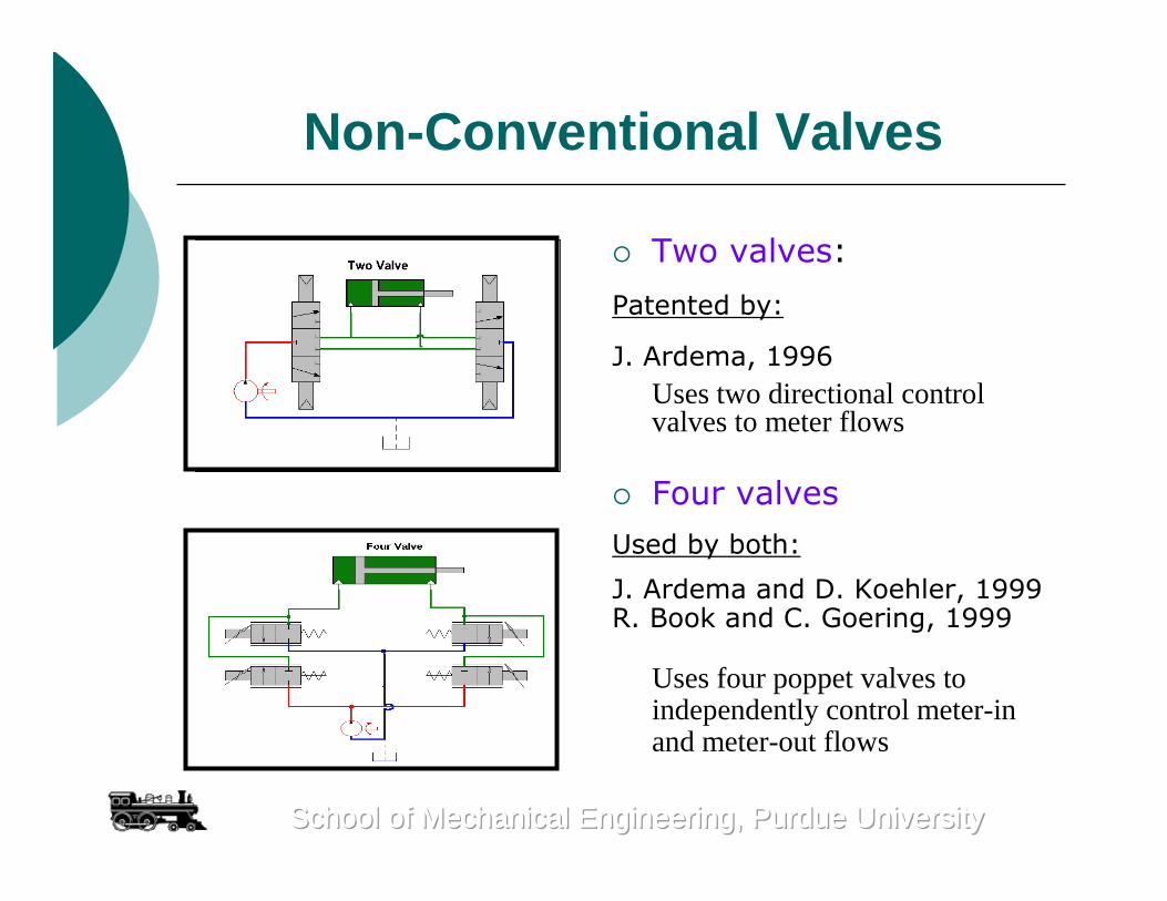
Non-Conventional Valves
Two valves:
Patented by:
J. Ardema, 1996Uses two directional control valves to meter flows
Four valves
Used by both:
J. Ardema and D. Koehler, 1999R. Book and C. Goering, 1999
Uses four poppet valves to independently control meter-in and meter-out flows
School of Mechanical Engineering, Purdue UniversitySchool of Mechanical Engineering, Purdue UniversitySchool of Mechanical Engineering, Purdue University
Regeneration Valves
Regeneration Valve
Patented by:K. Garnjost, 1989.
Uses one additional valve to provide regenerative flow for energy saving but cannot control both chambers independently
School of Mechanical Engineering, Purdue UniversitySchool of Mechanical Engineering, Purdue UniversitySchool of Mechanical Engineering, Purdue University
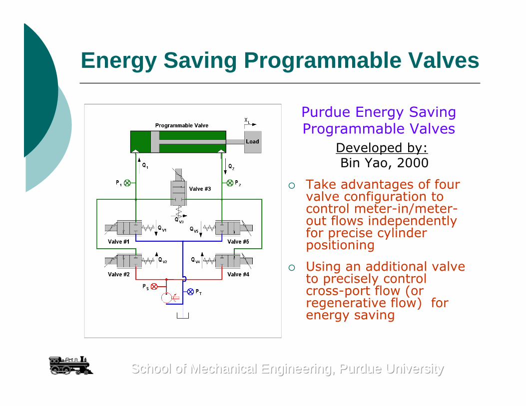
Energy Saving Programmable Valves
Purdue Energy SavingProgrammable Valves
Developed by:Bin Yao, 2000
Take advantages of four valve configuration to control meter-in/meter-out flows independently for precise cylinder positioning
Using an additional valve to precisely control cross-port flow (or regenerative flow) for energy saving
School of Mechanical Engineering, Purdue UniversitySchool of Mechanical Engineering, Purdue UniversitySchool of Mechanical Engineering, Purdue University
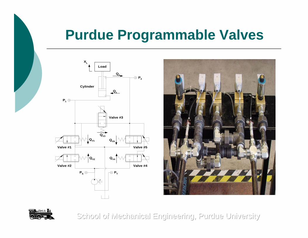
Purdue Programmable Valves
Cylinder
Valve #2
Load
Valve #5
Valve #4
Valve #3
Valve #1
XL
Q2
Q1
P1
P2
PS PT
QV1
QV2
QV5
QV4
QV3
School of Mechanical Engineering, Purdue UniversitySchool of Mechanical Engineering, Purdue UniversitySchool of Mechanical Engineering, Purdue University
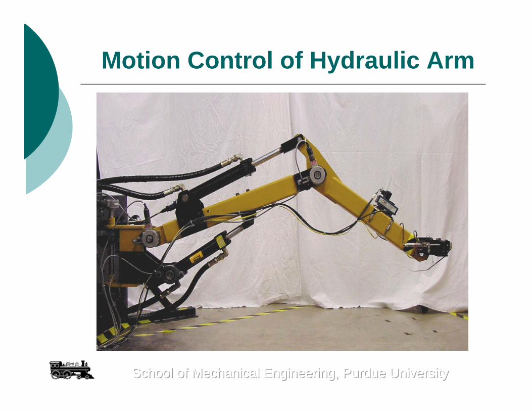
Motion Control of Hydraulic Arm
School of Mechanical Engineering, Purdue UniversitySchool of Mechanical Engineering, Purdue UniversitySchool of Mechanical Engineering, Purdue University
d 1
a 1
x0
z0
y0
q1
x1
y1
z1 α1=90 deg.
q2
x2
y2
z2
x3
y3
z3
-q3
Coordinate Systems of Hydraulic Arm
School of Mechanical Engineering, Purdue UniversitySchool of Mechanical Engineering, Purdue UniversitySchool of Mechanical Engineering, Purdue University
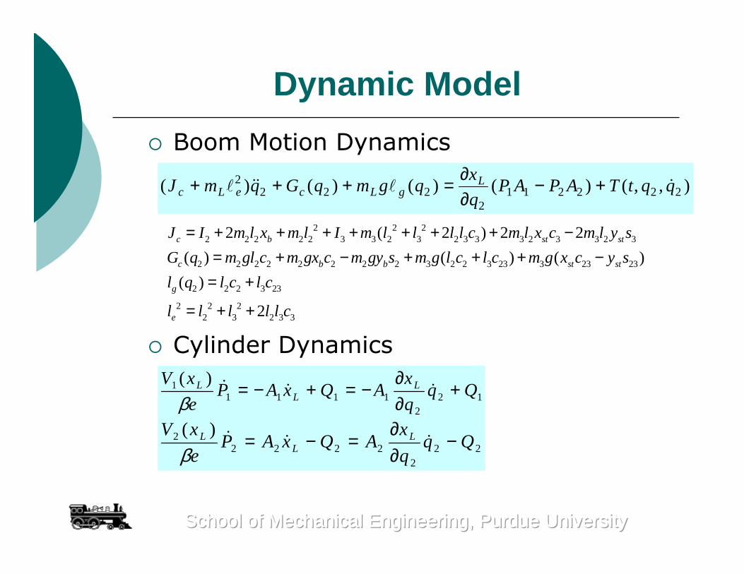
Dynamic Model
Boom Motion Dynamics
Cylinder Dynamics
),,()()()()( 2222112
2222 qqtTAPAP
q
xqgmqGqmJ L
gLceLc +−∂∂=+++
2 2 22 2 2 2 2 3 3 2 3 2 3 3 3 2 3 3 2 3
2 2 2 2 2 2 2 2 3 2 2 3 23 3 23 23
2 2 2 3 23
2 2 22 3 2 3 3
2 ( 2 ) 2 2
( ) ( ) ( )
( )
2
c b st st
c b b st st
g
e
J I m l x m l I m l l l l c m l x c m l y s
G q m gl c m gx c m gy s m g l c l c m g x c y s
l q l c l c
l l l l l c
= + + + + + + + −= + − + + + −
= +
= + +
School of Mechanical Engineering, Purdue UniversitySchool of Mechanical Engineering, Purdue UniversitySchool of Mechanical Engineering, Purdue University
122
11111 )(
Qqq
xAQxAP
e
xV LL
L +∂∂
−=+−=β
222
22222 )(
Qqq
xAQxAP
e
xV LL
L −∂∂
=−=β
Dynamic Model
Programmable Valve Flow Model
Valve Dynamics
3452
3121
vvv
vvv
QQQQ
QQQQ
−−=−−=
),(
),(
),(
),(
),(
5555
4444
3333
2222
1111
vvvv
vvvv
vvvv
vvvv
vvvv
xPfQ
xPfQ
xPfQ
xPfQ
xPfQ
∆=∆=∆=∆=∆=
1 1
2 1
3 1 2
4 2
5 2
v t
v s
v
v s
v t
P P P
P P P
P P P
P P P
P P P
∆ = −∆ = −∆ = −∆ = −∆ = −
School of Mechanical Engineering, Purdue UniversitySchool of Mechanical Engineering, Purdue UniversitySchool of Mechanical Engineering, Purdue University
2
2 2
( ) ( )
( ) ( ) 2vi v v
i v v v v
x s N s
v s D s s s
ωζ ω ω
= =+ +
Overall Strategies
The difficulties in the coordinated control of five cartridge valves for precision motion and pressure control are dealt with through a task level valve utilization (or mode selection) algorithm and local valve level ARC pressure and motion controllers.
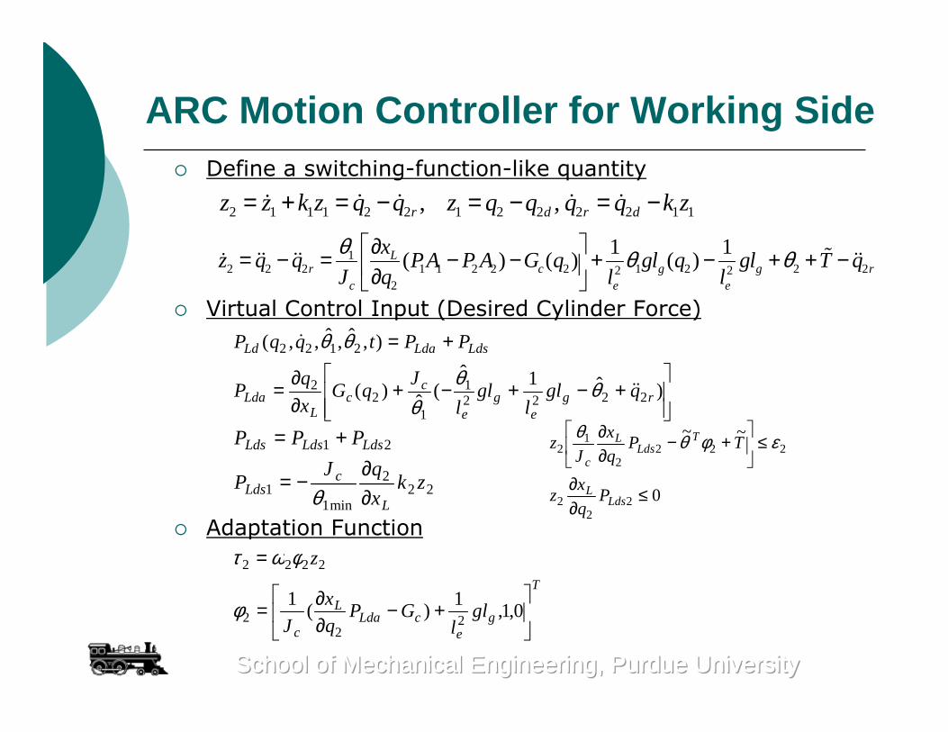
The nonlinear model based adaptive robust control (ARC) design in our previous studies is used to deal with the common difficulties in the precision control of electro-hydraulic systems directly to synthesize the desired load flow that is needed for precise motion control
nonlinear dynamics, large parameter variations, uncertain nonlinearities, and the mismatched model uncertainties
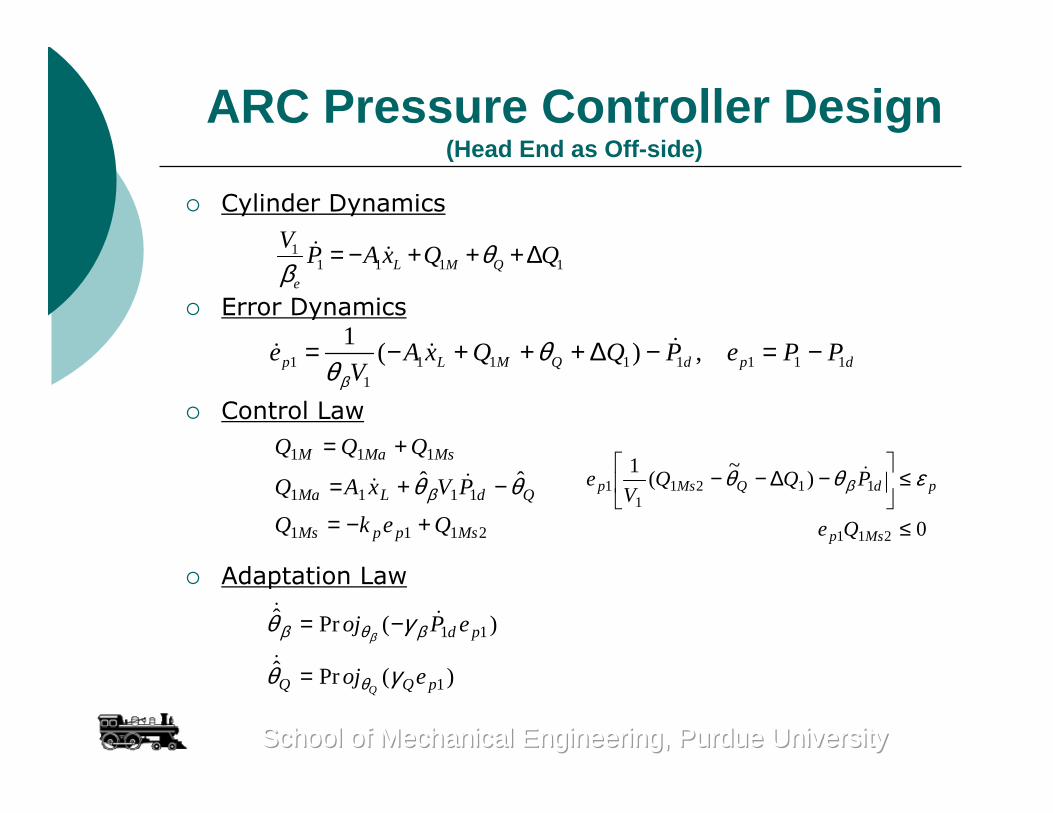
Nonlinear adaptive robust pressure controller is developed to handle the pressure control of the off-side chamber for energy saving purpose
School of Mechanical Engineering, Purdue UniversitySchool of Mechanical Engineering, Purdue UniversitySchool of Mechanical Engineering, Purdue University
Task Level Valve Utilization
Objective: Let Q1d and Q2d be the desired control flows to the two chambers of the cylinder that are needed to provide certain load pressure profile for motion tracking while maintaining the lowest possible cylinder chamber pressures to reduce the flow losses for energy saving. The task level of the controller determines how the five valves of the proposed programmable valve should be used in order to provide the required control flows Q1d and Q2d
Difficulties: Non-unique due to the added flexibility of independently controlling each of the five cartridge valves
Working Mode Selection:The paper uses seven modes, of which the first five are for motion tracking control and the last two for regulation control.
School of Mechanical Engineering, Purdue UniversitySchool of Mechanical Engineering, Purdue UniversitySchool of Mechanical Engineering, Purdue University
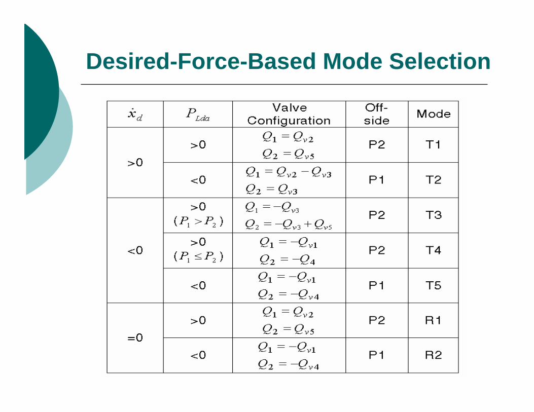
Desired-Force-Based Mode Selection
Extend Resistive Mode (T1)
Desired Velocity > 0Desired Control Force > 0
Uses valve #2 and valve #5Head-end (P1) for motion controlMaintain pressure of rod end (P2) as low as possible to have low working pressure for energy saving
Cylinder
Valve #2
Load
Valve #5
Valve #4
Valve #3
Valve #1
XL
Q 2
Q 1
P1
P2
PS PT
Q V2
Q V5
Extend Resistive-FLoad
School of Mechanical Engineering, Purdue UniversitySchool of Mechanical Engineering, Purdue UniversitySchool of Mechanical Engineering, Purdue University
Extend Overrunning Regeneration Mode (T2)
Desired Velocity > 0Desired Control Force < 0
Uses valve #2 and valve #3Rod-end (P2) for motion control through regeneration flow by valve #3 for significant energy savingMaintain head-end pressure (P1) as low as possible
Cylinder
Valve #2
Load
Valve #5
Valve #4
Valve #3
Valve #1
XL
Q 2
Q 1
P1
P2
PS PT
Q V2
ExtendOverrunning
FLoad
-QV3
School of Mechanical Engineering, Purdue UniversitySchool of Mechanical Engineering, Purdue UniversitySchool of Mechanical Engineering, Purdue University
ARC Pressure Controller Design(Head End as Off-side)
Cylinder Dynamics
Error Dynamics
Control Law
Adaptation Law
11 1 1 1L M Q
e
VP A x Q Qθ
β= − + + + ∆
1 1 1 1 1 1 1 11
1( ) ,p L M Q d p de A x Q Q P e P P
Vβ
θθ
= − + + + ∆ − = −
2111
1111
111
ˆˆ
MsppMs
QdLMa
MsMaM
QekQ
PVxAQ
QQQ
+−=
−+=
+=
θθβ
0
)~
(1
211
11211
1
≤
≤
−∆−−
Msp
pdQMsp
Qe
PQQV
e εθθ β
)(Prˆ
)(Prˆ
1
11
pQQ
pd
eoj
ePoj
Qγθ
γθ
θ
βθβ β
=
−=
School of Mechanical Engineering, Purdue UniversitySchool of Mechanical Engineering, Purdue UniversitySchool of Mechanical Engineering, Purdue University
ARC Motion Controller for Working SideDefine a switching-function-like quantity
Virtual Control Input (Desired Cylinder Force)
Adaptation Function
2 1 1 1 2 2 1 2 2 2 2 1 1, ,r d r dz z k z q q z q q q q k z= + = − = − = −
12 2 2 1 1 2 2 2 1 2 2 22 2
2
1 1( ) ( ) ( )L
r c g g rc e e
xz q q PA P A G q gl q gl T q
J q l l
θ θ θ ∂= − = − − + − + + − ∂
+−+−+
∂∂=
+=
)ˆ1ˆ(
ˆ)(
),ˆ,ˆ,,(
22221
12
2
2122
rge
ge
cc
LLda
LdsLdaLd
qgll
gll
JqG
x
qP
PPtqqP
θθθ
θθ
222
min11
21
zkx
qJP
PPP
L
cLds
LdsLdsLds
∂∂
−=
+=
θ 0
~~
22
2
2222
12
≤∂∂
≤
+−
∂∂
LdsL
TLds
L
c
Pq
xz
TPq
x
Jz εφθθ
T
ge
cLdaL
c
gll
GPq
x
J
z
+−
∂∂=
=
0,1,1
)(1
22
2
2222
φ
φωτ
School of Mechanical Engineering, Purdue UniversitySchool of Mechanical Engineering, Purdue UniversitySchool of Mechanical Engineering, Purdue University
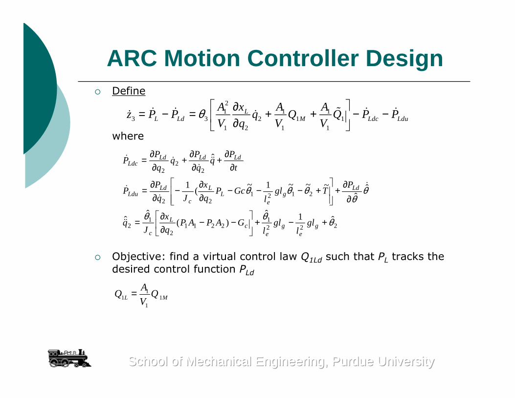
ARC Motion Controller DesignDefine
where
Objective: find a virtual control law Q1Ld such that PL tracks the desired control function PLd
21 1 1
3 3 2 1 11 2 1 1
LL Ld M Ldc Ldu
A x A Az P P q Q Q P P
V q V Vθ ∂= − = + + − − ∂
2221
22112
12
212122
22
2
ˆ1ˆ)(
ˆˆ
ˆˆ
~~~1~(
1
ˆ
θθθ
θθ
θθθ
+−+
−−
∂∂
=
∂∂
+
+−−−
∂∂
−∂∂
=
∂∂
+∂∂
+∂∂
=
ge
ge
cL
c
Ldg
eL
L
c
LdLdu
LdLdLdLdc
gll
gll
GAPAPq
x
Jq
PTgl
lGcP
q
x
Jq
PP
t
Pq
q
Pq
q
PP
11 1
1L M
AQ Q
V=
School of Mechanical Engineering, Purdue UniversitySchool of Mechanical Engineering, Purdue UniversitySchool of Mechanical Engineering, Purdue University
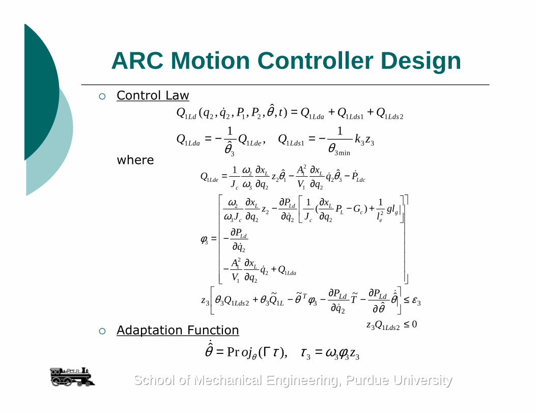
ARC Motion Controller DesignControl Law
where
Adaptation Function
1 2 2 1 2 1 1 1 1 2
1 1 1 1 3 33min3
ˆ( , , , , , )
1 1,
ˆ
Ld Lda Lds Lds
Lda Lde Lds
Q q q P P t Q Q Q
Q Q Q k z
θ
θθ
= + +
= − = −
22 1
1 2 1 2 33 2 1 2
22 2
3 2 2 2
32
21
2 11 2
1 ˆ ˆ
1 1( )
L LLde Ldc
c
LdL LL c g
c c e
Ld
LLda
x A xQ z q P
J q V q
Px xz P G gl
J q q J q l
P
q
A xq Q
V q
ω θ θω
ωω
φ
∂ ∂= − −∂ ∂
∂∂ ∂− − + ∂ ∂ ∂ ∂= −
∂ ∂ − +
∂
3 3 3 3ˆ Pr ( ),oj zθθ τ τ ω φ= Γ =
0
ˆˆ
~~~
213
32
3132133
≤
≤
∂∂
−∂∂
−−+
Lds
LdLdTLLds
Qz
PT
q
PQQz εθ
θφθθθ
School of Mechanical Engineering, Purdue UniversitySchool of Mechanical Engineering, Purdue UniversitySchool of Mechanical Engineering, Purdue University
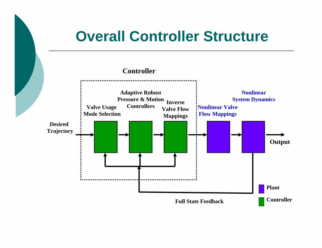
Overall Controller Structure
Valve UsageMode Selection
Adaptive Robust Pressure & Motion
Controllers Nonlinear Valve Flow Mappings
Inverse Valve Flow Mappings
NonlinearSystem Dynamics
DesiredTrajectory
Full State Feedback
Controller
Output
Controller
Plant
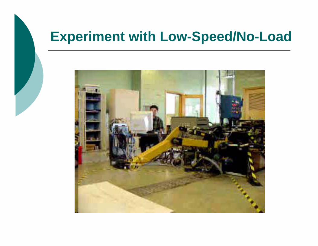
Experiment with Low-Speed/No-Load
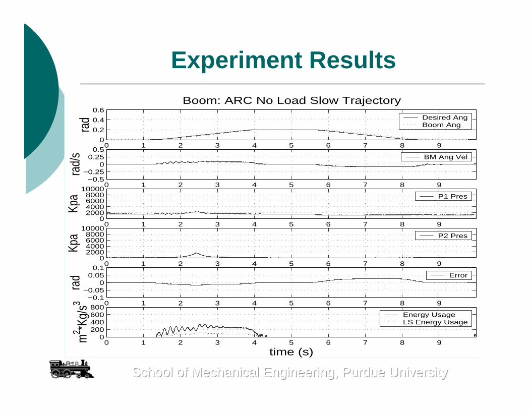
Experiment Results
0 1 2 3 4 5 6 7 8 90
0.2
0.4
0.6
rad
Boom: ARC No Load Slow Trajectory
Desired AngBoom Ang
0 1 2 3 4 5 6 7 8 9−0.5
−0.250
0.250.5
rad/
s BM Ang Vel
0 1 2 3 4 5 6 7 8 90
2000400060008000
10000
Kpa P1 Pres
0 1 2 3 4 5 6 7 8 90
2000400060008000
10000
Kpa P2 Pres
0 1 2 3 4 5 6 7 8 9−0.1
−0.050
0.050.1
rad Error
0 1 2 3 4 5 6 7 8 90
200400600800
m2 *K
g/s3
time (s)
Energy Usage LS Energy Usage
School of Mechanical Engineering, Purdue UniversitySchool of Mechanical Engineering, Purdue UniversitySchool of Mechanical Engineering, Purdue University
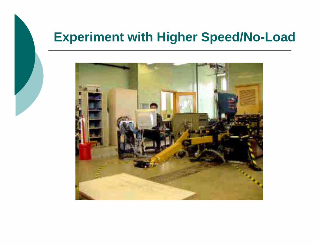
Experiment with Higher Speed/No-Load
Experiment Results
0 1 2 3 4 5 6 7 8 90
0.2
0.4
0.6
rad
Boom: ARC No Load Fast Trajectory
Desired AngBoom Ang
0 1 2 3 4 5 6 7 8 9−0.5
−0.250
0.250.5
rad/
s BM Ang Vel
0 1 2 3 4 5 6 7 8 90
2000400060008000
10000
Kpa P1 Pres
0 1 2 3 4 5 6 7 8 90
2000400060008000
10000
Kpa P2 Pres
0 1 2 3 4 5 6 7 8 9−0.1
−0.050
0.050.1
rad Error
0 1 2 3 4 5 6 7 8 90
200400600800
m2 *K
g/s3
time (s)
Energy Usage LS Energy Usage
School of Mechanical Engineering, Purdue UniversitySchool of Mechanical Engineering, Purdue UniversitySchool of Mechanical Engineering, Purdue University
Experiment with Low-Speed/50lb-Load
Experiment Results
0 1 2 3 4 5 6 7 8 90
0.2
0.4
0.6ra
dBoom: ARC Loaded Slow Trajectory
Desired AngBoom Ang
0 1 2 3 4 5 6 7 8 9−0.5
−0.250
0.250.5
rad/
s BM Ang Vel
0 1 2 3 4 5 6 7 8 90
2000400060008000
10000
Kpa P1 Pres
0 1 2 3 4 5 6 7 8 90
2000400060008000
10000
Kpa P2 Pres
0 1 2 3 4 5 6 7 8 9−0.1
−0.050
0.050.1
rad Error
0 1 2 3 4 5 6 7 8 90
200400600800
m2 *K
g/s3
time (s)
Energy Usage LS Energy Usage
School of Mechanical Engineering, Purdue UniversitySchool of Mechanical Engineering, Purdue UniversitySchool of Mechanical Engineering, Purdue University
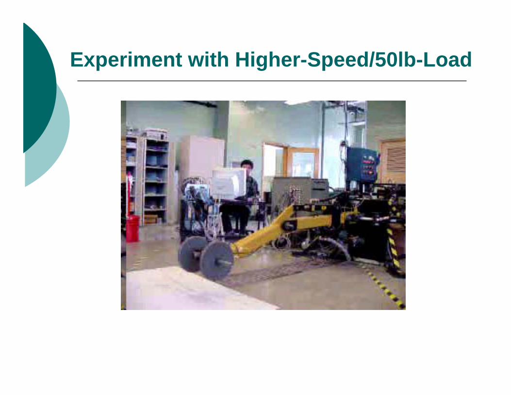
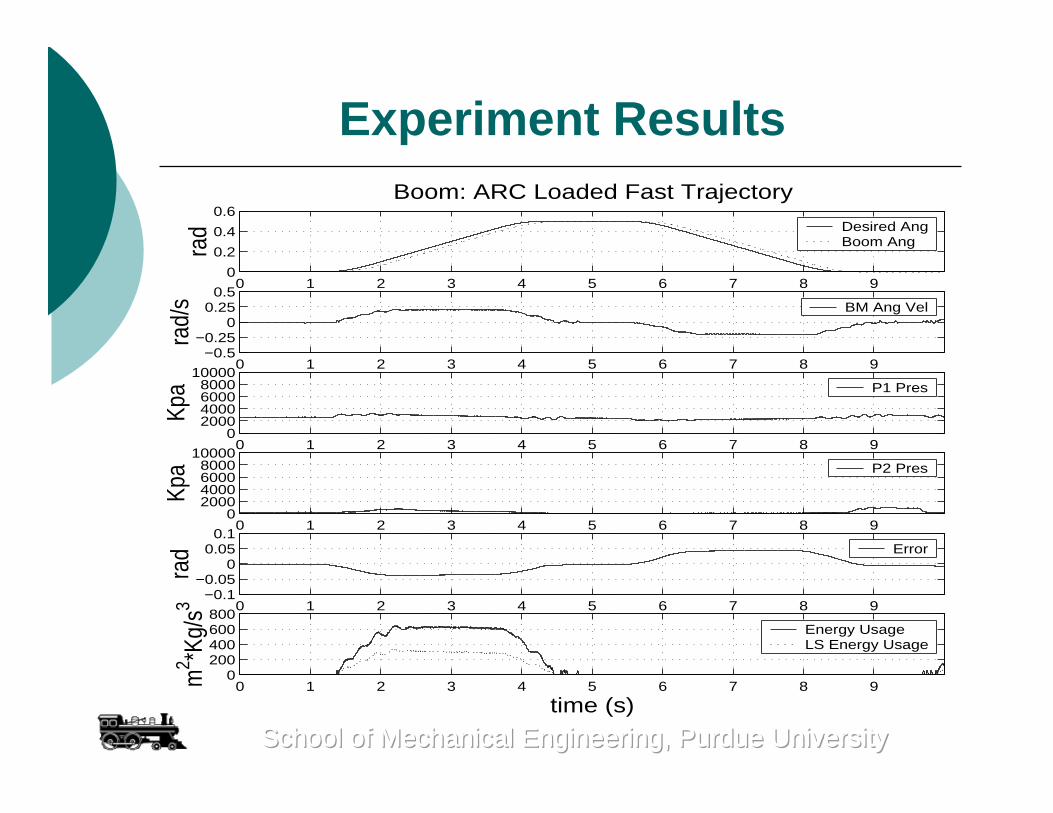
Experiment with Higher-Speed/50lb-Load
Experiment Results
0 1 2 3 4 5 6 7 8 90
0.2
0.4
0.6ra
dBoom: ARC Loaded Fast Trajectory
Desired AngBoom Ang
0 1 2 3 4 5 6 7 8 9−0.5
−0.250
0.250.5
rad/
s BM Ang Vel
0 1 2 3 4 5 6 7 8 90
2000400060008000
10000
Kpa P1 Pres
0 1 2 3 4 5 6 7 8 90
2000400060008000
10000
Kpa P2 Pres
0 1 2 3 4 5 6 7 8 9−0.1
−0.050
0.050.1
rad Error
0 1 2 3 4 5 6 7 8 90
200400600800
m2 *K
g/s3
time (s)
Energy Usage LS Energy Usage
School of Mechanical Engineering, Purdue UniversitySchool of Mechanical Engineering, Purdue UniversitySchool of Mechanical Engineering, Purdue University
CONCLUSIONS
The utilization of the programmable valve and proper ARC motion and pressure controllers results in significant gains in reducing pump energy usage while achieving reasonable tracking performance
The significant gains in energy saving is realized through precise control of regenerative flows in maintaining working-side chamber pressure for motion tracking while keeping off-side chamber pressure at desired low level
School of Mechanical Engineering, Purdue UniversitySchool of Mechanical Engineering, Purdue UniversitySchool of Mechanical Engineering, Purdue University
ACKNOWLEDGEMENTSACKNOWLEDGEMENTSSponsors:
National Science FoundationCAREER Grant CMS-9734345