General rights Copyright and moral rights for the publications made accessible in the public portal are retained by the authors and/or other copyright owners and it is a condition of accessing publications that users recognise and abide by the legal requirements associated with these rights. Users may download and print one copy of any publication from the public portal for the purpose of private study or research. You may not further distribute the material or use it for any profit-making activity or commercial gain You may freely distribute the URL identifying the publication in the public portal If you believe that this document breaches copyright please contact us providing details, and we will remove access to the work immediately and investigate your claim. Downloaded from orbit.dtu.dk on: Jul 14, 2020 Energy use and indoor environment in new and existing dwellings in Arctic climates Kotol, Martin Publication date: 2014 Document Version Publisher's PDF, also known as Version of record Link back to DTU Orbit Citation (APA): Kotol, M. (2014). Energy use and indoor environment in new and existing dwellings in Arctic climates.
Transcript
General rights Copyright and moral rights for the publications made accessible in the public portal are retained by the authors and/or other copyright owners and it is a condition of accessing publications that users recognise and abide by the legal requirements associated with these rights.
Users may download and print one copy of any publication from the public portal for the purpose of private study or research.
You may not further distribute the material or use it for any profit-making activity or commercial gain
You may freely distribute the URL identifying the publication in the public portal If you believe that this document breaches copyright please contact us providing details, and we will remove access to the work immediately and investigate your claim.
Downloaded from orbit.dtu.dk on: Jul 14, 2020
Energy use and indoor environment in new and existing dwellings in Arctic climates
Kotol, Martin
Publication date:2014
Document VersionPublisher's PDF, also known as Version of record
Link back to DTU Orbit
Citation (APA):Kotol, M. (2014). Energy use and indoor environment in new and existing dwellings in Arctic climates.
This thesis is a result of a Ph.D. study carried out at the Section of Building Physics at the Department of Civil Engineering at the Technical University of Denmark (DTU). The Ph.D. was financed by a scholarship from DTU. Professor Carsten Rode, Ph.D. has been the main supervisor of the project while Associate Professor Geo Clausen, Ph.D. and Associate Professor Toke Rammer Nielsen, Ph.D. acted as co-supervisors.
Majority of the experimental work was performed in the town of Sisimiut, Greenland. In 2012 Jack Hébert hosted an 8 months external research stay at Cold Climate Housing Research Centre (CCHRC) in Fairbanks, Alaska in connection with the study.
The work is based on scientific papers that are enclosed in the end of the thesis.
Lyngby, January 2014
Martin Kotol
iii
ACKNOWLEDMENTS
I want to acknowledge the financial, academic and technical support of the Technical University of Denmark. I would also like to express my gratitude to the KVUG, Idella and Otto Mønsted foundations for their funding that provided the necessary financial support for this research.
Furthermore, I would like to thank to my main supervisor, Professor Carsten Rode for his support during the entire Ph.D. project. Carsten would always find a gap in his full calendar for discussion. His good advice and support have been invaluable on both an academic and a personal level, for which I
am very grateful.
I also want to thank to my co-supervisor Geo Clausen for his advices during preparations of the questionnaire study and the indoor environmental measurements. Without his inputs it would not be possible to perform the cross sectional study to such a broad extent. Likewise my thanks belong to my other co-supervisor Toke Rammer Nielsen for his support during past years. Toke would always respond to my questions in no time and scientific discussions we had, have always been a great inspiration for my work.
I would like to offer my very special thanks to Jack Hébert who has invited me to Alaska for an external stay. Jack with his big hearth and open mind has been a great inspiration to me professionally and personally. In this respect I would like to show my appreciation to the entire crew at Cold Climate Housing Research Center in Fairbanks for accepting me as a colleague and friend and for making me feel like a part of their big family.
My special thanks belong to my friend Rasmus Kruse Nielsen and his wife Themona for their friendly support during my work in Sisimiut.
I owe a very important debt to my friends and colleagues Tomáš Mikeska, Marek Brand, Jiří Hykš and Andrea Proctor Spilak for reading through, correcting and commenting on my thesis as well as for the countless discussions on scientific and personal topics. I also want to acknowledge all the colleagues from the section of Building Physics and Services for providing a friendly, inspiring and supportive environment.
Many thanks to my friends in the Czech Republic for keeping in touch and finding time to meet for productive discussions in Zelená Kočka during my visits in Brno. Moreover my great thanks belong to all members of a Czech gang in Denmark. In particular to the entire Farum branch for always providing me with great company along with fantastic food, drinks, shelter and entertainment.
One of my biggest thanks is to my brother David, my parents and grandparents as well as to the rest of my family. They were always supporting me and encouraging me with their best wishes.
My last and greatest thanks are addressed to my wife Barbora and our son Adam. Adam although only few weeks old, already understood that I need to concentrate and cried as little as possible. Barbora was always there cheering me up and stood by me through the good times and bad. For their endless patience and support this thesis is dedicated mainly to them.
v
SUMMARY
Buildings in Arctic climates require large amounts of heat to provide their occupants with a comfortable indoor environment. In recent years the intention to conserve energy has caused buildings in the Arctic (and worldwide) to become more insulated and airtight. The natural infiltration of buildings is being reduced to avoid heat loss and unpleasant air drafts, often without proper compensation. Many studies have shown that living in insufficiently ventilated spaces increases the risk for asthma and allergy symptoms. However, the indoor environment in Arctic dwellings has seldom been investigated.
For energy and indoor environmental reasons it is advisable that new airtight buildings be equipped with mechanical ventilation systems with heat recovery. Nevertheless, these systems when exposed to the Arctic winter climate face the risk of frost formation, which may put the ventilation system out of order for long periods or potentially damage it.
The main objectives of the work described in this thesis have been: A) to provide new knowledge about optimal operation and performance of low energy technologies in the Arctic and B) to map the indoor environmental quality in dwellings in the Arctic.
The first part of this thesis provides an overview of three case studies undertaken in newly built residential buildings in Greenland and Alaska. It was found that ventilation systems in these buildings are either under or oversized which has a significant negative effect on their indoor air quality or energy use respectively. One of the evaluated buildings in Greenland had ventilation units that were not equipped with the frost protection and as a result, serious ice buildups appeared inside the heat exchangers. The prototype heat exchanger developed at the Technical University of Denmark and installed in the Low Energy House in Sisimiut had experienced an unnoticed malfunction for the first 3 years of operation. However, after repairing the heat exchanger it was capable of continuous operation without freezing and reached an average thermal effectiveness of 69 %. In Alaska, three out of four ventilation systems studied in new homes used recirculation as a method of frost protection. This strategy allowed a continuous operation of the ventilation system; however, the fresh air supply was reduced significantly during winter months.
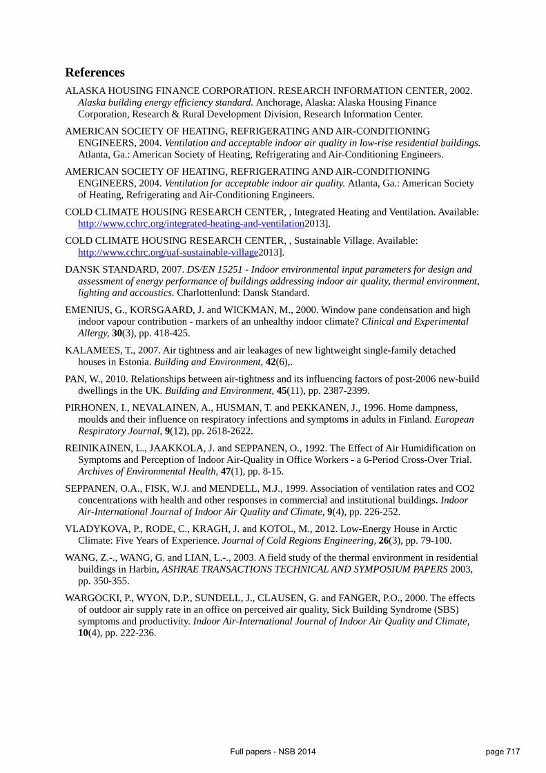
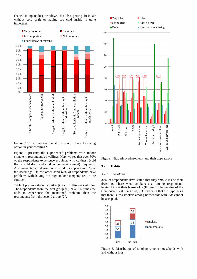
The second part of the thesis presents a cross sectional study on indoor air quality performed in Sisimiut, Greenland. A questionnaire as part of the study found that over 30 % of respondents experience cold discomfort during winter months (i.e. cold floors, cold draft or too low indoor temperature), 35 % of the respondents reported frequent condensation on windows. Despite the cool summers 40 % of the respondents complained about summer overheating. It was also found that 34 % of the respondents smoke inside their homes. Additionally it was revealed that ventilation equipment is typically limited to fresh air openings on walls, mechanical exhausts from bathrooms (present in 63 % of the dwellings) and kitchen range hoods (installed in 82 % of the dwellings). Presence of balanced mechanical ventilation was not reported by any of the respondents.
The questionnaire study was followed by summer and winter measurements in bedrooms of 79 dwellings selected among dwellings inhabited by the questionnaire respondents. The winter measurements indicate that 73 % of the monitored bedrooms experienced average additional moisture higher than 2.5 g/kg or average night CO2 concentration above 1000 ppm and 59 % of bedrooms had experienced both. This indicates that the majority of the monitored bedrooms were
vi
insufficiently ventilated. The problems with poor ventilation were more severe in newer buildings (build after 1990) due to tighter envelopes and unchanged ventilation strategies.
In conclusion, it is possible to provide dwellings in the Arctic with good indoor environment. However, this is largely dependent on the design of buildings and their ventilation systems. The ventilation should not rely on simple wall openings as they prove to be inefficient in providing continuous air change at a sufficient rate without creating thermal discomfort.
vii
DANSK RESUMÉ
Bygninger i arktiske klimaer kræver meget varme for at sikre et komfortabelt indeklima for brugerne. Som følge af de senere års intentioner om at spare energi er bygninger i arktiske områder (og resten af verden) blevet bedre isoleret og mere lufttætte, og den naturlige infiltration i bygningerne er blevet reduceret for at undgå varmetab og trækproblemer, ofte uden tilstrækkelig kompensation. Mange studier har vist, at ved at leve i utilstrækkeligt ventilerede bygninger øges risikoen for astma og allergi symptomer, men indeklimaet i arktiske huse er sjældent blevet undersøgt.
Med hensyn til energi og indeklima er det en god idé at installere mekaniske ventilationssystemer i nye lufttætte bygninger, også selvom ventilationssystemer opsat i arktiske egne har risiko for at blive udsat for frost, der kan sætte ventilationssystemet ud af drift i længere perioder eller ligefrem beskadige det.
Hovedmålet med arbejdet beskrevet i denne afhandling er: A) At give ny viden om optimal drift og ydeevne af lavenergi teknologier i arktiske egne, og B) At anskueliggøre kvaliteten af indeklimaet i boliger i arktiske egne.
Den første del af afhandlingen giver et overblik over tre cases af nybyggede boliger i Grønland og Alaska. Det viste sig at ventilationssystemerne i disse boliger var enten under- eller overdimensioneret, hvilket har en stor negativ effekt på hhv. indeklimaet eller energiforbruget. En af case bygningerne havde ventilationsenheder som ikke var udstyret med frostsikring, hvilket resulterede i alvorlige isdannelser inden i varmevekslerne. I en anden case så man at den prototype varmeveksler der blev udviklet på DTU og installeret i Lav Energi Huse i Grønland havde en fejl der ikke var blevet opdaget de første 3 år den var i drift. Efter fejlen var fundet og repareret var varmeveksleren i stand til at fungere uden at fryse til og nåede en gennemsnitlig effektivitet på 69 %. I Alaska brugte tre ud af fire undersøgte ventilationssystemer recirkulation som frostsikring. Denne strategi gør det muligt for ventilationssystemet at fungere hele året, men mængden af frisk luft der bliver blæst ind i vintermånederne er stærkt reduceret.
Den anden del af afhandlingen omhandler et studie af luftkvalitet i bygninger foretaget i Sisimiut, Grønland. Et spørgeskema, der var en del af studiet, viste at over 30 % af respondenterne oplevede at der var for koldt gennem vinter månederne (f.eks. kolde gulve, træk eller for lav inde temperatur), og 35 % oplevede ofte kondens på vinduerne. På trods af kolde somre, så svarede 40 % at de oplevede overophedning om sommeren. Ydermere fandt man at 34 % af beboerne ryger inde i deres hjem. Derudover blev det kortlagt at ventilationsudstyr ofte kun består af simple friskluftåbninger i vægge, mekanisk udsugning fra badeværelset (i 63 % af boligerne) og køkkenudsugning i form af emhætte (installeret i 82 % af boligerne). Der var ingen balancerede ventilationssystemer blandt besvarelserne.
Spørgeskemaundersøgelsen blev fulgt op af målinger foretaget i sommer og vinter i soveværelser i 79 boliger, udvalgt blandt spørgeskemabesvarelserne. Vinter målingerne indikerede at 73 % af de undersøgte soveværelser havde en gennemsnitlig fugt differens mellem ude og inde på over 2,5 g/kg, eller en gennemsnitlig CO2 koncentration på over 1000 ppm om natten, i 59 % af soveværelserne oplevede man begge dele. Dette indikerer at størstedelen af de undersøgte soveværelser ikke var ventileret ordenligt. Problemerne med dårlig ventilation var værst i nyere bygninger (bygget efter 1990) pga. deres tætte klimaskærm og uændrede ventilationsstrategi.
viii
Konklusionen er at det er muligt at give boliger i Arktiske egne et godt indeklima. Dog er det meget afhængigt af designfasen af bygninger og dertilhørende ventilationssystemer. Ventilation bør ikke være afhængig af simple åbninger i vægge, da de har vist sig at være ineffektive i forhold til at kunne levere et kontinuerligt luftskifte, med en tilstrækkelig luftmængde, der ikke skaber termisk ubehag.
Paper II .............................................................................................................................................. 79
Paper III ........................................................................................................................................... 101
Paper IV ........................................................................................................................................... 111
Paper V ............................................................................................................................................ 121
I. Vladykova P., Rode C., Kragh J., Kotol M. Low-Energy House in Arctic Climate: Five Years of Experience. Journal of Cold Regions Engineering 2012, (26), p. 79-100.
II. Kotol M., Rode C., Vahala J. Energy performance and Indoor Air Quality in Modern Buildings in Greenland. Accepted to HVAC&R Research (in January 2014)
III. Kotol M., Craven C., Rode C. Survey of Indoor Air Quality in the University of Alaska, Fairbanks - Sustainable Village. Part of proceedings: Nordic Symposium of Building Physics 2014, Lund-Sweden
IV. Kotol M. Survey of occupant behaviour, energy use and indoor air quality in Greenlandic dwellings. Part of proceedings: International Building Physics Conference 2012, Kyoto-Japan
V. Kotol M., Rode C., Nielsen T.R., Clausen G. Indoor Environment in Bedrooms in 79 Greenlandic Households. Building and Environment 2014, (81), p.29-36
xii
ADDITIONAL WORK (NOT INCLUDED IN THE THESIS)
• Stevens V., Kotol M., Grunau B., Craven C. The Effect of Thermal Mass on Annual Heat Load and Thermal Comfort in Cold Climate Construction. Submitted to ASHRAE 2014 Annual conference
• Rode C., Vladykova P., Kotol M. Air Tightness and Energy Performance of an Arctic Low- Energy House. Proceedings of Build Air Symposium 2012, Copenhagen
• Kotol M. Survey of occupant behaviour, energy use and IAQ in Greenlandic dwellings.
Proceedings of ARTEK Event 2012, Sisimiut
• Kotol M., Rode C., Vahala J. Blower door tests of a group of identical flats in a new student accommodation in the Arctic. Proceedings of TightVent conference 2013, Athens
• Kotol M. HVAC system in new dormitory Apisseq in Sisimiut, Greenland. International
workshop at Nordic Housing Forum 2012, Alta
• Kotol M., Rode C. Energy performance and IAQ in modern buildings in Greenland. Energy Efficient Buildings workshop 2012, Brno
• Kotol M. Indeklilma: Sisimiut-husstande med i detaljeret undersøgelse. Sermitsiaq 14-2011
• Kotol M. Water use in engineering dormitory in Greenland - Apisseq. BYG Internal Report R
278, 2012
• Kotol M. APISSEQ Sisimiut – Greenland: 1st winter survey 2011. BYG Internal Report SR 11-01, 2011
• Kotol M., Rode C., Vladykova P., Furbo S., Borchersen E. Low-energy house in Sisimiut:
Annual report of Low-energy house performance July 2009 to June 2010. BYG Internal Report
• Vladykova P., Kotol M. Monitoring system in new dormitory APISSEQ, Sisimiut, Greenland.
The Arctic climate is rather cold and dry, so living inside heated buildings results in significant energy consumption. In Greenland (which was the main region of interest of this PhD study) households account for 25 % (of which 85 % is heat and 15 % electricity) of the total energy consumption [2]. For comparison, in EU-27 households are responsible for 24 % of energy use [3]. Given the fact that another 25 % of the Greenlandic energy is used to actually deliver energy and water to the consumer (including households), the real contribution of households to the overall energy use is higher than 25 %.
Relatively small amounts of insulation have been used in the exterior envelope of buildings until recently [1]. These constructions have been rather drafty which further decreases the interior surface temperature towards the dew point. Consequently, structural damages and indoor moisture and mold problems are not uncommon in this otherwise “dry climate”. Although the thermal indoor climate has not been satisfactory, the energy consumption for heating has been rather high; Greenlandic average heat consumption was 387 kWh/m2 in 2009 [2] which is 141 % more than the Danish average heat consumption [4,5].
Obvious solutions to decrease the heat consumption while maintaining good indoor air quality (IAQ) are (i) to improve the building envelope by tightening and increasing the insulation thickness, and (ii) to install ventilation systems that can provide the dwelling with sufficient air change. The ventilation systems can be equipped with heat recovery to reduce the energy needed for heating the fresh air supply. Nonetheless, the cold and dry outdoor climate renders a challenge for using mechanical ventilation systems. In efficient heat recovery units where warm and humid indoor air meets the cold outdoor air, condensation and subsequent frost formation may arise and eventually turn the entire device into a block of ice. Note that preheating of supply air may be applied to cope with this issue. However, such a solution is energy consuming. Alternatively, smarter heat recovery units may be used, but it must be kept in mind that availability of skilled labor is limited and fixing a broken unit may take months.
Insufficient ventilation leads to increased humidity levels and poor IAQ which may have negative effects on health and comfort of occupants [6-10]. This can be dealt with by applying proper air change which would (besides removing unwanted pollutants) remove a fraction of the moisture. Nevertheless, improperly managed air change during extremely cold and thus dry weather may lead to low indoor humidity which is also unacceptable since it may cause problems such as skin irritation, mucous membranes irritation or sensation of dryness [11].
Overall, there is a significant challenge in providing the inhabitants of buildings in Arctic climates (i.e. not only in Greenland) with good indoor environment, provided this should be completed in an energy efficient manner. The problem is relevant in relation to an assessment of the standard of current buildings, and their possible renovations. The problem is also relevant for assessing the performance of new buildings such as the Low Energy House in Sisimiut and the new dormitory for engineering students Apisseq [II]. Experience from the Low Energy House [I] (now nine years old) has shown that direct application of low energy technologies used in milder climate to conditions prevailing in the Artic is not straightforward and may be quite challenging [12].
2
The aim of the present PhD project has been to evaluate the technical solutions of new state of the art residential buildings in the Arctic with respect to IAQ and energy use. Particular focus has been put on ventilation systems and their performance in these buildings. Furthermore, user behavior, energy use and IAQ have been investigated in existing Greenlandic dwellings.
The entire project has been divided into two major parts. In the first part three case studies were conducted on three residential building projects: 1) The Low Energy House in Sisimiut, Greenland [I]; 2) the engineering dormitory Apisseq in Sisimiut, Greenland [II] and finally 3) The Sustainable Village in Fairbanks, Alaska [III]. Results from these studies were presented in separate papers I, II and III.
The second part was dedicated to the studies of user behavior, energy use and IAQ in existing dwellings in Greenland. It started with the cross sectional questionnaire study performed in Sisimiut, Greenland (presented in paper IV) and was followed up with a cross sectional study in 79 dwellings selected from the respondents of the questionnaire study (presented in paper V).
3
2 OBJECTIVES AND HYPOTHESIS
The main objectives of this work have been:
A. To provide new knowledge about actual operation and performance of low energy technologies in the Arctic; and
B. To map the IAQ, energy consumption and occupant behavior in Greenland.
The first objective was addressed in the following publications which are referred to in the thesis by their roman numerals:
I. Low-Energy House in Arctic Climate: Five Years of Experience Vladykova P., Rode C., Kragh J., Kotol M. Journal of Cold Regions Engineering 2012, (26), p. 79-100.
II. Energy performance and Indoor Air Quality in Modern Buildings in Greenland Kotol M., Rode C., Vahala J. Accepted to HVAC&R Research (in January 2014)
III. Survey of Indoor Air Quality in the University of Alaska, Fairbanks - Sustainable Village Kotol M., Craven C., Rode C. Submitted to Nordic Symposium of Building Physics 2014, Lund-Sweden
Similarly, the second objective was addressed in the following publications:
IV. Survey of occupant behaviour, energy use and indoor air quality in Greenlandic dwellings Kotol M. Part of proceedings: International Building Physics Conference 2012, Kyoto-Japan
V. Indoor Environment in Bedrooms in 79 Greenlandic Households Kotol M., Rode C., Nielsen T.R., Clausen G. Submitted to Building and Environment (in January 2014)
The hypotheses of this work have been:
A. It is possible to install mechanical ventilation systems with heat recovery into dwellings in the Arctic while ensuring their continuous operation in harsh Arctic conditions and keeping them simple enough in order to be installed and maintained by local craftsmen thus providing the Arctic dwellings with good IAQ and substantially reducing the energy consumption.
B. In Greenland, the development of ventilation techniques of homes has not been
following the development of airtightness of the building envelopes and requirements on IAQ which has led to poorer air change and consequently poorer IAQ in new dwellings.
4
5
3 STRUCTURE
This PhD project studied the indoor environment of residential buildings in cold climates, and systems providing these buildings with good indoor air quality in the Arctic. Throughout the duration of the project three case studies and one cross sectional study were conducted.
The thesis is divided into two main parts.
Part I. addresses the first objective. Three case studies are presented here:
The case study Low Energy House in Sisimiut, Greenland (article I), was conducted at the beginning of this PhD project. In this study the performance of a ventilation system with prototype heat exchanger developed for cold climates was studied.
The second case study was on the engineering dormitory Apisseq (article II). It is an ongoing project co-financed by DTU. This recently built dormitory in Sisimiut was equipped with a complex monitoring system in order to study its performance and IAQ. Energy performance of the entire building, performance of the ventilation system and IAQ are studied.
The third case study was undertaken in Fairbanks, Alaska. IAQ in the new Sustainable Village (which is a group of four residential homes constructed using state of the art technology) was performed. This case study is presented in article III.
The second objective is addressed in Part II of this thesis. A comprehensive cross sectional study was conducted in Sisimiut, to map the IAQ, energy use and habits of people living in the Arctic. It started with a cross sectional questionnaire study (article IV) and continued with a follow-up study where physical measurements were performed in selected dwellings (article V).
6
7
4 BACKGROUND
4.1 Arctic
The Arctic is a region located close to the North Pole mainly within the Arctic Circle (66° 33’N). It is comprised of the Arctic Ocean, parts of Russia, United States, Canada, Norway, Sweden, Finland, Iceland and Denmark (Greenland).
4.1.1 Weather
The climate in the Arctic is cold. Although it varies across the Arctic and differs from coastal to inland, it is characterized by long lasting winters with extremely low temperature and little sunlight. Summers are then cool and short with sunlight lasting as long as 24 hours/day (midnight sun).
4.1.2 People
There are about 4 million people living in the Arctic [13]. According to available studies, people spend around 65 % of their time inside their homes [14,15]. In Canada the time spent indoors is longer in winter (69 %) than during summer (58 %), and more time in the case of children under 11 years of age than in the case of adults (72.3 % vs. 64.3 %)[15].
4.1.3 Energy
Living inside the heated space in such cold climate requires significant amounts of energy. In northern Sweden, the average annual use of energy for space heating in 2006 was 174 kWh/m2 in multifamily buildings, and 143 kWh/m2 in one- and two-family buildings [16]. The overall average energy use in Norwegian households in 2009 was 181 kWh/m2, but the municipalities with the coldest climate had an average as high as 223 kWh/m2 [17]. The fact that 18.5 % of households in Norway are heated by heat pumps makes it impossible to distinguish between heating and appliance energy use. In Finland, the average heating energy in 2012 was 260 kWh/m2 and the electricity use for household appliances was 36 kWh/m2 [18]. In Canada 230 kWh/m2 of energy in was used in 2007 [19]; of which 86 kWh/m2 was electricity in some cases used as a primary heating source. Overall, the average energy use for heating and DHW of dwellings in the Arctic (excluding Greenland) ranges between 143 kWh/m2 and 260 kWh/m2.
4.2 Greenland
Greenland is the world’s largest island located between the Arctic and Atlantic Ocean. 81 % of Greenland’s 2,166,086 km2 area is covered permanently by an ice sheet and most of the island lies above the Arctic Circle. The population of Greenland is approximately 56,000 people of which most are living in cities and settlements along the west coast. 30 % of the population lives in the capital Nuuk, which is located on the west coast, 240 km south of the Arctic Circle [2].
4.2.1 Weather in Greenland
The climate in most cities is coastal, but since the sea freezes in the winter time in most cities north of the Arctic Circle (Sisimiut 66°55’N being the northernmost ice-free harbor), extreme temperatures can be as low as -50 °C. The average February temperature can get as low as -20 °C in some cities [20]. The ability of cold air to carry moisture is limited so even though the relative humidity during
8
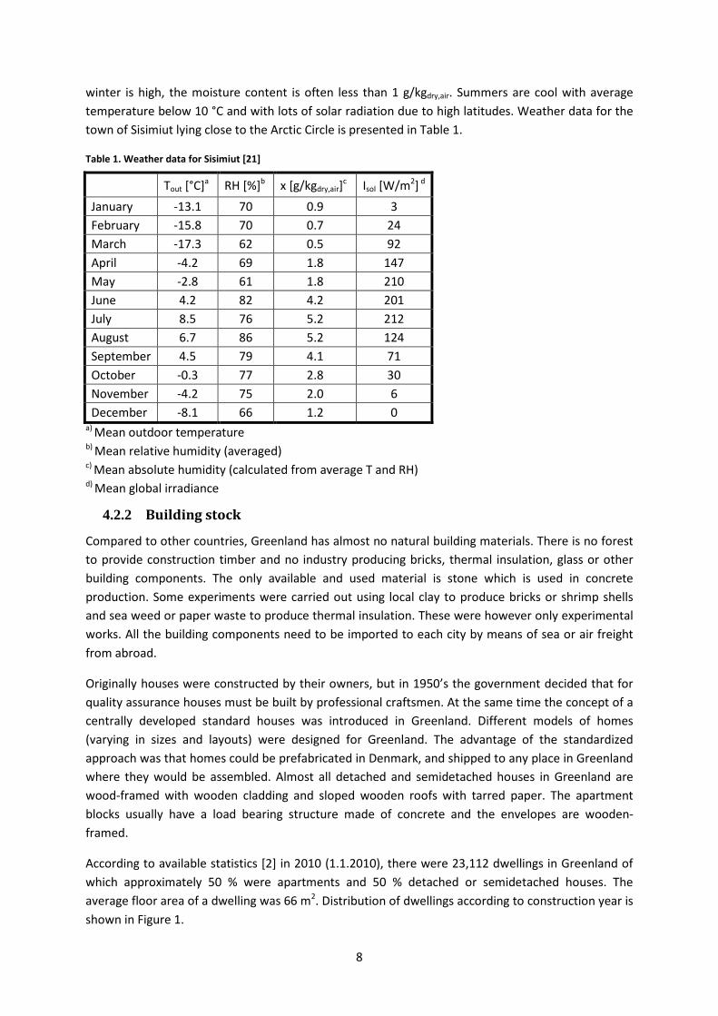
winter is high, the moisture content is often less than 1 g/kgdry,air. Summers are cool with average temperature below 10 °C and with lots of solar radiation due to high latitudes. Weather data for the town of Sisimiut lying close to the Arctic Circle is presented in Table 1.
Table 1. Weather data for Sisimiut [21]
Tout [°C]a RH [%]b x [g/kgdry,air]c Isol [W/m2] d January -13.1 70 0.9 3 February -15.8 70 0.7 24 March -17.3 62 0.5 92 April -4.2 69 1.8 147 May -2.8 61 1.8 210 June 4.2 82 4.2 201 July 8.5 76 5.2 212 August 6.7 86 5.2 124 September 4.5 79 4.1 71 October -0.3 77 2.8 30 November -4.2 75 2.0 6 December -8.1 66 1.2 0
a) Mean outdoor temperature b) Mean relative humidity (averaged) c) Mean absolute humidity (calculated from average T and RH) d) Mean global irradiance
4.2.2 Building stock
Compared to other countries, Greenland has almost no natural building materials. There is no forest to provide construction timber and no industry producing bricks, thermal insulation, glass or other building components. The only available and used material is stone which is used in concrete production. Some experiments were carried out using local clay to produce bricks or shrimp shells and sea weed or paper waste to produce thermal insulation. These were however only experimental works. All the building components need to be imported to each city by means of sea or air freight from abroad.
Originally houses were constructed by their owners, but in 1950’s the government decided that for quality assurance houses must be built by professional craftsmen. At the same time the concept of a centrally developed standard houses was introduced in Greenland. Different models of homes (varying in sizes and layouts) were designed for Greenland. The advantage of the standardized approach was that homes could be prefabricated in Denmark, and shipped to any place in Greenland where they would be assembled. Almost all detached and semidetached houses in Greenland are wood-framed with wooden cladding and sloped wooden roofs with tarred paper. The apartment blocks usually have a load bearing structure made of concrete and the envelopes are wooden-framed.
According to available statistics [2] in 2010 (1.1.2010), there were 23,112 dwellings in Greenland of which approximately 50 % were apartments and 50 % detached or semidetached houses. The average floor area of a dwelling was 66 m2. Distribution of dwellings according to construction year is shown in Figure 1.
9
Figure 1. Distribution of Greenlandic dwellings according to year of construction [22]
4.2.3 Energy use and price
In 2009 the average Greenlandic household used 4,689 kWh (71 kWh/m2) of electricity and 25.6 MWh (387 kWh/m2) of heat [2]. There is some small portion of electricity used for electric heating, but that cannot be separated from the total electricity use. This is by far the highest average energy use per square meter of living area from all available statistics for any Arctic country.
It has been shown in previous studies [23,24] that occupant behavior has a significant impact on the energy consumption of buildings. These studies were conducted in milder climates. Nevertheless, it can be expected that in an Arctic environment where people spend more time inside their homes during winter than in milder climates, the effect of occupant behavior on energy consumption will be greater than in milder climates.
In EU and many other countries a strong driving force for energy savings is the high cost of energy. This makes the investment into energy efficient technologies cost-effective in a relatively short time. On the other hand, In Greenland the energy is relatively cheap due to low taxation, but the price of installation of new technologies is higher than in Europe due to lack of competition and high transportation costs. As a result, new energy efficient technologies for better energy performance and healthier indoor environment are not commonly used even in new Greenlandic buildings. However, with increasing energy prices and demands on healthy indoor environment, it is possible that there will be an increasing demand for use of modern energy efficient technologies which will be able to operate in harsh arctic conditions. Nevertheless, designers and contractors have either no or limited experience with these technologies and that causes hindrance to the adoption and proper use of these technologies in Greenland.
0
5000
10000
15000
20000
25000
< 19
66
1966
- 19
69
1970
- 19
79
1980
- 19
89
1990
- 19
99
2000
- 20
09
Num
ber o
f dw
ellin
gs
Built
Total
7718 Built before 1970
9932 Built 1970 - 1990
5462 Built after 1990
10
4.2.4 Energy and IAQ requirements in Greenland
The current building code in Greenland is from 2006 [25]. This code sets limits on maximum thermal transmittances of the building envelope and also on the total energy use for heating and ventilation. According to this building code, Greenland is divided into two zones (Zone 1: south of the Arctic Circle; Zone 2: north of the Arctic Circle) and maximum permissible energy use for heating and ventilation is calculated from respectively Eq. 1 and Eq. 2, where e is the ratio between the heated area of a dwelling and its footprint area. Results calculated for different numbers of floors are shown in Table 2.
Zone 1: [ ])/(280420 2 yrmMJe
⋅+ (1)
Zone 2: [ ])/(350510 2 yrmMJe
⋅+ (2)
Table 2. Maximum permissible energy use for heating and ventilation in two zones in Greenland according to actual building regulation
Unlike the current Danish building regulation [26] where the requirement on airtightness at 50 Pa of the envelope is set to 1.5 l/s per m2 of heated floor area for ordinary buildings and 1.0 l/s per m2 in case of low energy buildings, the Greenlandic building code does not yet have any requirement on airtightness of buildings.
Regarding IAQ, the Greenlandic building code requires an air exchange rate of 0.5 h-1 in all living spaces as well as in the entire building. The following rooms should be equipped with an air extraction: Kitchens (20 l/s), toilets (10 l/s) and bathrooms (15 l/s). The extraction can be mechanical, but ventilation openings of an area of 200 cm2 (in each of the rooms requiring exhaust) are considered as a sufficient alternative. Supply of fresh air into living spaces can be provided by mechanical supply or ventilation openings as large as 30 cm2 for every 25 m2 of floor area in buildings with mechanical exhaust, or 60 cm2 for every 25 m2 in naturally ventilated buildings.
11
4.2.5 Summary
The high heat consumption of Greenlandic dwellings is probably caused by combination of various factors of which the major ones are likely a) the extreme climatic conditions, b) an old building stock, which is often constructed by unskilled workers or self-builders, c) no or low requirements on thermal insulation and airtightness, d) an energy price policy which does not motivate people to save energy, and e) occupant behavior.
Paradoxically the high heat consumption does not necessarily result in a good indoor climate. If a building is constructed in accordance with the actual ventilation requirements, the ventilation equipment can be limited to simple air vents in walls. Therefore, all the ventilation elements can be easily blocked by occupants to avoid cold draft during winter months. This will result in a reduction of air exchange and consequently in poor IAQ. Even though there is not yet a requirement on airtightness in the Greenlandic building code, the construction techniques have improved over the years and building envelopes have become more airtight. Consequently, newer dwellings may in fact have poorer IAQ than older ones due to less natural infiltration and unimproved ventilation strategies.
12
13
5 PART I - OPTIMAL OPERATION AND PERFORMANCE OF LOW ENERGY TECHNOLOGIES IN THE ARCTIC
This part investigates the recently constructed buildings and their performance with respect to IAQ and energy use.
5.1 Specific background
With the intention to conserve energy used in buildings the building envelopes have become more airtight to eliminate the heat loss from infiltration. This leads to a situation where natural air change is no longer sufficient for good IAQ. To compensate for the reduction of natural air change ventilation systems are installed in new buildings. These systems allow better control over the actual ventilation rate and also offer the possibility for heat recovery by means of heat exchangers.
5.1.1 Heat exchangers
Heat exchangers (HE) are devices in which the warm air extracted from the indoor space exchanges heat with the cold supply air without actual mixing of the two air streams. Thanks to this device, a significant amount of energy which would otherwise be lost is conserved. Depending on the construction of the heat exchangers they can either recover only heat or heat and moisture which can be beneficial in the Arctic where the outside air is dry.
When the temperature of the outside air drops below the dew point of the extracted air, condensation may arise inside the HE. Additionally, if the outside temperature is below the freezing point, ice buildup may start inside the HE. To prevent HE from getting entirely blocked by ice some frost protection strategy is needed. The most commonly used strategies are preheating of the supply air before it enters the HE and/or bypassing of the supply air from the HE [27]. Another option often used in North America is air recirculation (see Figure 2).
Figure 2. Recirculation as a defrosting function
With air recirculation as a frost protection strategy the ventilation unit blocks the fresh air supply and exhaust into/ out of the house and recirculates the indoor air inside the house for a period of time to melt the frost from the HE [28]. Preheating and by-passing decrease the overall efficiency of the HE; air recirculation, on the other hand, reduces the air change with the outdoors. All these strategies are sufficient in mild climates as defrosting is only needed for a limited amount of time. In cold climates however, the frost protection may be required for substantial periods of the year, and it is
14
therefore important that it is completed as efficiently as possible. The performance of a prototype HE with unique frost protection function is studied in [I]. Average thermal effectiveness of 69 % and capability of continuous operation during winter time was ensured by using two heat exchangers in serial connection. Malfunction of the prototype was experienced during the first years of operation, but after its correction in 2009 the HE performs as anticipated. Conventional HEs are studied in [II,III]. The ventilation unit in [II] was not equipped with defrosting function which led to frequent ice buildups and likely to a damage of the HE resulting in its low effectiveness. The ventilation units studied in [III] were capable of operation in temperatures below -30 °C with average thermal effectiveness higher than 70 %. However, the defrosting strategy (recirculation) significantly decreased the average air change rate.
5.1.2 Air flow control
Traditionally ventilation systems for homes run on the constant air volume (CAV) basis which means they maintain a constant predefined air change rate. However, studies show that a great deal of energy savings without sacrificing the IAQ can be achieved by the use of more sophisticated methods like variable air volume (VAV) systems or demand controlled ventilation (DCV) [29]. In VAV there are usually two predefined modes (low/high or ON/OFF) of the ventilation between which the ventilation unit switches according to schedule. DCV on the other hand adjusts the ventilation rate to maintain a predefined IAQ. This adjustment could be continuous or step based (low/high or ON/OFF).
15
5.2 Low Energy House in Sisimiut, Greenland
5.2.1 Introduction
The Low Energy House was built in the town of Sisimiut in 2005. The house is comprised of two identical flats with a shared entrance and technical room. One flat is being rented to a Greenlandic family while the other remains empty and serves as an exhibition, for occasional accommodation of VIPs and as a test facility. The total heated floor area (including the entrance which was originally meant to be unheated) is 208 m2. State of the art technology was used in order to meet the target annual heat consumption of 80 kWh/m2. Highly insulated envelope closed for vapor diffusion by means of vapor barrier [Ufloor = 0.14 W/(m2·K); Uwall = 0.15 W/(m2·K); Uroof = 0.13 W/(m2·K)] was designed with a special focus on elimination of thermal bridges. Although the Greenlandic building code does not require it, a large focus was also placed on airtightness. The average infiltration rate was intended to be under 0.1 h-1. Different window/glazing types were used including double pane glazing with vacuum [Uglass = 0.7 W/(m2·K)]. The house is heated by a hydronic floor heating system with an oil furnace as primary heat source and 7.4 m2 of solar panels as a secondary source. As the very first residential house in the town, the Low Energy House was equipped with a balanced ventilation system with a prototype heat recovery unit. The uniqueness of the heat recovery unit lies in its defrosting strategy where the order of two counter flow heat exchangers in a series can be switched by a mechanical damper (see Figure 3).
Figure 3. Scheme of the heat exchanger function
The heat exchanger is described in detail by Kragh [30] and by Kotol [31]. The fresh air is preheated in the heat exchanger, after that it is heated in a heating coil and delivered into corridors and living rooms. Polluted air is then extracted from bedrooms, bathrooms, the technical room and entrance and travels through the heat exchanger out of the house. The ventilation runs on CAV basis which means that even during unoccupied hours (almost 100 % of the time in case of the uninhabited apartment) the house is ventilated at a constant ventilation rate. The ductwork is placed in an unheated attic and was originally insulated by 50 mm of mineral insulation. In 2009 some additional 100 mm of insulation was added around the ventilation ducts.
5.2.2 Methods
Over the course of 5 years the performance of the house was monitored by a built-in monitoring system. In 2009/2010 an audit was undertaken in the house which revealed a series of defects. The major errors were: a) thermosiphoning in the solar collector loop, b) malfunctioning of the defrosting
16
mechanism inside the heat exchanger, c) excessive heat loss through the ventilation ducts and d) poor airtightness. The errors revealed during the audit were fixed and energy use decreased significantly in the upcoming year compared to the data from previous years. The fixing of the errors included a) installing a check valve on the solar loop, b) welding the broken damper in the heat exchanger, c) adding an extra 100 mm of thermal insulation on the ventilation ducts and d) improving the wind barrier layer of the envelope by sealing leaks discovered during replacement of parts of the wooden cladding. The airtightness was tested twice (before and after the audit) by means of blower door test. Measured values and uncertainty of measurements is shown in Table 3.
Table 3. Uncertainties of measurements at LEH
Variable Uncertainty Room temperature ± 0.4 K at 5 °C – 60 °C Room RH ± 4.5 % at RH 20 % - 80 %; else ± 7.5 % Air temperature in ventilation units ± 0.25 K at 0 °C – 50 °C; ± 0.75 K at -40 °C – 0 °C Heat ± (0.5 + DTmin/DT) % Air flow during blower door test ± 5 % Ventilation air flow ± 10 %
5.2.3 Results
The temperature effectiveness of the heat exchanger was lower than 60 % during the first three years of operation which was a result of the non-functioning switching damper and thus air leaking (by-passing) of the two plate heat exchangers. After fixing the damper in December 2009, the effectiveness increased significantly to the average 69 % in 2010. The box plot in Figure 4 displays a distribution of measured thermal efficiencies in separate years. The bottom and upper parts of the boxes are 25th
and 75th percentile of the data, whereas the ends of the whiskers represent the lowest
(highest) datum, but still within 1.5 times the inter quartile range (75th percentile – 25th percentile). The bands inside the boxes are medians and the crosses outside the whiskers are the outliers.
Figure 4. Temperature effectiveness distribution over years of operation
17
The average effectiveness was also affected by the defrosting strategy where the order of the two counter flow heat exchangers changes in preset cycles (see Figure 5). After each switch the colder heat exchanger gets heated by the exhaust air and possible ice formed in the previous cycle is melted (hence the drop in effectiveness) meanwhile the other heat exchanger is on the colder side (in contact with the fresh outside air) and therefore gets cooled and eventually the ice formation starts. The switching is shown on a model in Figure 6.
Figure 5. Temperature effectiveness during 2 hours switching cycles
Figure 6. Switching of the heat exchangers
After adding an extra 100 mm of insulation on all the ventilation ducts in the attic, the heat transfer coefficient decreased from U50mm = 0.545 W/(m·K) to U150mm = 0.241 W/(m·K). This reduced the heat loss from the ducts by approximately 56 %.
The results of both blower door tests (before and after the tightening) showed that the airtightness of the house did not change significantly and is worse than expected (see Table 4). The average air change at normalized pressure from both measurements yields qinf = 0.29 h-1 (see [I] for more details). The contribution of higher infiltration to the total heat loss was estimated to be 9,000 kWh/a or 43.3 kWh/(m2·a) which is 210 % more than if the airtightness was as low as anticipated.
20%
40%
60%
80%
-20-10
010203040
00:0
0
04:0
0
08:0
0
12:0
0
16:0
0
20:0
0
Effic
ienc
y [%
]
Tem
pera
ture
[°C
]
Texhaust[°C]Textract [°C]Tsupply [°C]Tout[°C]Efficiency η [%]
18
Table 4. Results of the blower door tests
Method / Date At differential pressure of 50 Pa At normalized pressure
Airflow V50 [l/s]
Air change rate w50 [l/(s·m2) @ 50 Pa]
Air change rate n50 [h-1 @ 50 Pa]
Leakage rate q50 [l/(s·m2)]
Infiltration rate qinf [h-1]
Blower-door, Feb 2009 474 2.55 3.35 2.28 0.30
Blower-door, Mar 2010 436 2.35 3.07 2.10 0.28
Internal building volume Vnet = 510 m3, net floor area Anet = 186 m2. Unit convert: 1 l/s = 3.6 m3/h
The heat consumption in the first years of operation was up to 100 % higher than initially designed and simulated value (HE effectiveness used for simulation was 80 %; for other input values see Table 5 in [I]). However after the adjustments in 2009 the total heat consumption decreased to 90 kWh/(m2·a) in 2010 which is 12.5 % more than the designed value.
5.2.4 Discussion
The switching of the HE as a defrosting strategy does control the frost accumulation inside the HE (so it is capable of continuous operation) but decreases the efficiency of the heat exchange. Currently it is turned on continuously all year round which reduces the overall efficiency even during periods when freezing is not an issue. It is likely that deactivating the function during periods when frost formation is improbable would further increase the annual average efficiency of the HE.
Additional insulation of the ventilation ducts has decreased the heat loss considerably. However, the remaining heat loss still contributes to the overall heat consumption. Putting as large a portion of the building services systems as possible inside the insulated envelope would minimize the heat loss from these components.
It was believed that improving the wind barrier layer of the walls would improve the airtightness significantly. Nevertheless, this showed not to be the case as most of the leaks explored were at door and window frames, floor/wall and ceiling/wall joints and not through the walls themselves. Testing the airtightness earlier in the construction phase (before the walls were closed) would have allowed discovering and fixing the leaks. This would result in achieving the desired airtightness.
A significant improvement was realized after the corrections in 2009/2010. After the adjustments the annual heat consumption was 12.5 % higher than the design value which is likely due to higher infiltration loss and heat loss from ventilation ducts. Fixing these two issues to bring the consumption down to the design value at this stage of the building would require extensive work and investment which would likely not be cost effective.
19
5.3 Engineering dormitory Apisseq, Greenland
This chapter summarizes the work which has been done on the case study “Apisseq”. The main results are presented here. Details including building description, methodology and more results are presented in [II] and in reports and conference papers [32-34]. Energy consumption data and the HE data were updated with the most recent data to provide a better overview of the performance of the building. This updated data has not been published before.
5.3.1 Introduction
The engineering dormitory Apisseq was built in Sisimiut, Greenland in 2010. The Technical University of Denmark has contributed with 500,000 DKK to equip the building with a monitoring system to study its performance. It is a round shaped building (see Figure 7) with 1,414 m2 of heated area. It consists of a basement with technical rooms and storage compartments and two floors with 33 identical single person flats and 4 larger apartments at the gables. The intention was to build an energy efficient building in which modern technologies not yet commonly used in the Arctic could be installed tested and thus promoted.
The knowledge gained from the Low Energy House in Sisimiut served as a starting point for the design process. The energy use should be minimized by using highly insulated and airtight envelope [Uwall = 0.15 W/(m2·K); UFloor= 0.13 W/(m2·K); URoof = 0.13 W/(m2·K); Uwall = 0.15 W/(m2·K); Uwindows = 1.1 W/(m2·K)] and utilizing the solar energy. 38 evacuated tubular solar collectors were placed on the roof charging two accumulation tanks 2 m3 each - placed in a technical room. The estimated annual heat demand was 169.7 kWh/m2.
To ensure good IAQ the building was equipped with a mechanical ventilation system with heat recovery. Two identical air handling units were placed in the gables of the building, each of them providing a symmetrical half of the building with air supply and exhaust. The fresh air supply is at a constant rate whereas the exhaust is demand controlled by humidistats in bathrooms and two position dampers in kitchen range hoods.
The building was equipped with a monitoring system [34] which documents its performance. The energy in and out flows are monitored to provide an overview of the energy performance. Energy produced by the solar heating plant, energy delivered by the district heating system and the distribution of this energy among domestic hot water (DHW), ventilation system and space heating are monitored. The temperature, relative humidity and CO2 concentration are monitored in five selected flats in order to study the IAQ. Additionally the entire building was tested for airtightness in summer 2012.
20
Figure 7. Floor plans of the engineering dormitory Apisseq
5.3.2 Methods
Airtightness and thermal bridges
A blower door test in a single flat was performed in winter 2011 along with a thermo-graphic screening in order to reveal possible air leaks and thermal bridges [32]. Each flat in the building was tested during summer 2012 for airtightness by means of a blower door test [33]. In order to estimate the air change between the adjacent flats, a tracer gas experiment was conducted in 6 neighboring flats.
Indoor climate
Two periods, each consisting of three successive days, were selected for indoor climate evaluation. During one period the ventilation was under normal operation, whereas during the second period the ventilation was out of order because the air channels in the heat exchanger were blocked by frost. Out of five constantly monitored flats only four were occupied representing 10.5 % of the entire building.
Temperature, relative humidity and CO2 concentration were measured in the living space of each of the four flats continuously in 1 minute intervals. The air flows were measured in each flat once with a flow measuring hood placed at the air terminal devices.
Ventilation units
Since balanced ventilation systems with heat recovery are rare in Greenland, monitoring the performance of the system installed in Apisseq was of great interest. The following variables related to the ventilation units’ performance are constantly being monitored by the monitoring system: 1) Temperatures and RH in all four air connections to the unit 2) Supply and return air flows 3) Pressure drop over the heat exchanger and 4) Fan speed. In addition to the continuous monitoring, the units were examined visually during winter 2011 [32].
21
Energy flows
During the first few months the monitoring system was not completely finished, therefore manual readings of the energy meter from the district heating company had to be taken in order to obtain the monthly heat consumption (for details see paper II.). Since November 2011 the readings from all the sensors and energy meters have been available online (with some breaks due to internet breakdowns) and a detailed analysis has therefore been possible.
Uncertainty of measurements
The uncertainties of measurements can be seen in Table 5. All used sensors were brand new and calibrated by their manufacturers. For more details about used sensors, calibration and accuracy see [34].
Table 5. Uncertainties of measurements at Apisseq
Variable Uncertainty Room temperature ± 0.3 K at 0 °C – 50 °C Room RH ± 3 % at RH 30 % - 70 %; ±5 % else CO2 concentration ± 2 % of range; ±2 % of reading Temperature inside the ventilation units ± 1 K RH inside the ventilation units ± 2.5 % Air flows inside the ventilation units ± 10 % Pressure drop over the heat exchanger ± 1.5 % Heat ± (0.5 + DTmin/DT) % Air flow during blower door test ± 5 %
5.3.3 Results
Airtightness and thermal bridges
The overall measured mean specific leakage at 50 Pa pressure difference was equal to 2.05 l/(s·m2). Ten out of thirty seven flats in the building (27 %) would pass the Danish requirement having the specific leakage lower than 1.5 l/(s·m2) [the average of all ten flats was 1.1 l/(s·m2)]. One of the flats showed to be significantly more leaky than the rest [w50 = 5.5 l/(s·m2) see Figure 8].
Figure 8. Specific leakage (w50) and air change (n50) at 50 Pa pressure difference in all 37 flats at Apisseq
The tracer gas measurements showed that there is no significant air change between the adjacent flats which is likely due to the internal structure of monolithic concrete (internal walls and ceilings). The major part of the natural air change takes place with the outside environment.
During the thermo graphic screening and observations, some design and construction errors were found which had a negative effect on the airtightness and heat loss [32]. The lack of an installation space between the vapor barrier and inner sheetrock showed to be one of the design problems related to airtightness. As the vapor barrier is placed right behind the sheetrock, its multiple penetrations were needed (for electricity and heating fixtures). Figure 9 shows an example of such penetration (and subsequent air leakage) of a vapor barrier by a light fixture cable in a bathroom.
Figure 9. Air leakage caused by penetration of the vapor barrier with electric cable for a bathroom light (the image on the left side is taken with thermo graphic camera)
Indoor climate
The measurements of the airflows revealed that the actual air change rate in the single room flats equals to 1.2 h-1 (or 19.4 l/s) which is 140 % more than what the Greenlandic building code requires for living rooms. Given the amount of air change it is not surprising that the concentration of CO2 is low. During the three day period with the mechanical ventilation system under normal operation (see Figure 10) the average night time CO2 concentration in the monitored rooms was 560 ppm and in three out of four rooms, the CO2 concentration never exceeded 900 ppm (which is the recommendation for category II. of indoor environment given in EN 15251 [35]).
Figure 10. Cumulative percentage distribution of CO2 concentrations during the night (22:00 - 08:00) with the ventilation system ON and OFF as stated in brackets
During the breakdown of the ventilation units (more on breakdowns in the paragraph on ventilation units) the CO2 concentration exceeded the limit of the sensor (2,500 ppm) in three of the four monitored rooms for periods ranging from 5 % to 85 % of the monitored nights. The measured average night time CO2 concentration in the flats reached 1519 ppm and was above the recommended 900 ppm room for at least 60 % of the monitored nights in each. However, the actual average CO2 concentration was likely higher as the limit of used sensors is 2000 ppm.
The measurements show that except for a short period in one of the flats, the RH during normal operation had not exceeded 35 % (see Figure 11). When interviewing the occupants of the dormitory, common complaints included irritation of skin or mucous membranes due to dry air.
Figure 11. Relative humidity in the four measured flats (The boxes describe the lower and upper quartiles, the bands inside the boxes are medians, crosses are mean values and the ends of the whiskers represent 5th and 95th percentiles. The values in the boxes above each box plot are means)
When comparing the two 3-day periods with and without an operating ventilation system (Table 6) it was found that the heat consumption per HDD was 36 % higher when the ventilation system was running.
Table 6. Heat consumption with ventilation system ON/OFF
Ventilation [ON/OFF]
Heating degree days [HDD]
Heat consumption [kWh]
Heating demand [kWh/HDD]
ON 78.5 2,245 28.6
OFF 80.7 1,706 21.1
Ventilation units
31.2
47.4
26.6
30.7
29.9
41.9
30.5
34.9
20
25
30
35
40
45
50
55
60
65
70
Flat
1.0
2 (O
N)
Flat
1.0
2 (O
FF)
Flat
1.0
7 (O
N)
Flat
1.0
7 (O
FF)
Flat
1.1
6 (O
N)
Flat
1.1
6 (O
FF)
Flat
2.0
2 (O
N)
Flat
2.0
2 (O
FF)
Rela
tive
hum
idity
[%]
24
The visual observations revealed serious frost formations in one of the heat exchangers and accumulation of snow in the fresh air intake chamber of the ventilation unit (see Figure 12). The frost formation was found to be a result of missing defrosting mode which was not ordered by the contractor. The snow accumulated in the intake chamber was transported there with the supply air during period when it was snowing as the air intake on the façade is insufficiently protected.
Figure 12. Frost formation in the heat exchanger and snow accumulation in the intake chamber
Figure 13. Temperature effectiveness of the HE in Apisseq
0%15%30%45%60%75%90%105%120%135%150%
-20-15-10
-505
1015202530
12-1
2-20
1213
-12-
2012
14-1
2-20
1215
-12-
2012
16-1
2-20
1217
-12-
2012
18-1
2-20
1219
-12-
2012
20-1
2-20
1221
-12-
2012
22-1
2-20
1223
-12-
2012
24-1
2-20
1225
-12-
2012
26-1
2-20
1227
-12-
2012
28-1
2-20
1229
-12-
2012
30-1
2-20
1231
-12-
2012
01-0
1-20
1302
-01-
2013
03-0
1-20
13
Effic
ienc
y [%
]
Tem
pera
ture
[°C]
He
atin
g po
wer
[kW
]
After heater power [kW] Outside temperature [°C]
Supply air into rooms [°C] Supply air before afterheating [°C]
Return air from rooms [°C] Temperature efficiency - RETURN [%]
Temperature efficiency - SUPPLY [%]
25
From the effectiveness chart during December 2012 (see Figure 13) it can be seen that the actual temperature effectiveness of the HE is around 45 % (43.8 % is an average for the shown period). Low thermal effectiveness causes that the return air is not cooled below freezing point and thus the frost formation does not appear.
Energy
The 12 months running average heat consumption for heating and DHW between November 2011 and October 2013 (Table 7) was 219.7 kWh/m2 of which 21.6 kWh/m2 (9.8 %) was covered by the solar panels and the remaining 198.2 kWh/m2 by district heating. On average, 55.7 MWh (21 % of the total annual heating consumption) is dedicated to post heating of the ventilation air.
Table 7. Twelve months heat consumption in a period from November 2012 until October 2013
Ventilation Space heating DHW Total
DH Total solar
contribution Total
12 months period
[MWh] 55.7 204.0 51.1 280.2 30.5 310.7
[kWh/m2] 39.4 144.2 36.1 198.2 21.6 219.7
In Figure 14 it can be seen that there is a demand for space heating even during the summer months. The heat demand gets partially covered by the solar system, but even in July there is a need for district heating to cover the remaining heat demand.
Figure 14. Monthly and annual energy use and distribution
5.3.4 Discussion
The airtightness of the Apisseq similar to LEH would not fulfill the Danish requirement 1.5 l/(s·m2). This requirement however does not apply to Greenland. One of the identified reasons for poor airtightness is the lack of an installation space between the vapor (airtight) barrier and the inner sheetrock. Designing this installation gap would minimize the amount of vapor barrier penetrations and would lead to an improvement of airtightness.
0
5
10
15
20
25
30
35
40
45
Jan
- 12
Feb
- 12
Mar
- 12
Apr -
12
May
- 12
Jun
- 12
Jul -
12
Aug
- 12
Sep
- 12
Oct
- 12
Nov
- 12
Dec
- 12
Ener
gy u
se [M
Wh]
Ventilation [MWh] Total DH [MWh]Space heating [MWh] Total Solar [MWh]DHW [MWh]
0
50
100
150
200
250
300
350
Ener
gy u
se [M
Wh]
26
Significantly poorer airtightness of one of the flats indicates some abnormality due to construction errors in this flat. In general large variation in results (given the fact that most of the flats are identical) suggests that there have been some issues with quality craftsmanship during construction. Like in the LEH, also in Apisseq the construction errors related to airtightness could have been revealed and fixed by performing the blower door test earlier such as during the construction phase.
The high ventilation rate aside from having positive effects on the concentration of indoor pollutants, also has some drawbacks. The indoor environmental downside of such high air change is a low indoor humidity. The indoor air humidified by the indoor moisture sources (human breathing, cooking, showering, indoor plants) is removed at a high rate and replaced with the outdoor air, which contains almost no moisture during a large part of the year. Another issue related to a high air change rate is increased energy consumption.
The reason for designing such a high air change was likely due to the fact that part of the living space is a kitchen which according to requirements must have an air exhaust of 20 l/s which (in case of balanced ventilation) also means an air supply of 20 l/s. Nevertheless, it is likely that the actual cooking only takes place for short period each day and for the rest of the time the space is over ventilated without a reason. Moreover since the building is a dormitory most of the flats are empty (yet still ventilated) during school hours. Designing a VAV system with a demand control would deliver the minimal amount of air according to the occupancy and activity level. This would substantially reduce the heat demand of the ventilation system which is now over 20 % of the total annual heat consumption. At the same time this solution would not sacrifice the IAQ during occupied hours.
The missing defrosting function in the ventilation units as a result of poor selection causes the heat exchangers to freeze completely during the first winter and put the entire ventilation system out of order. It is suspected that the frequent frost formation on the HE at the start of the building operation had damaged the HE, as its thermal effectiveness is currently 45 %. This hypothesis would however have to be confirmed by inspecting the unit, as the measurements before the first winter are not available and therefore the original thermal effectiveness cannot be estimated. Poor effectiveness prevents the HE from further freezing, but at the same time increases the heat demand for the supply air heating and hence increases the entire building’s energy use.
The snow accumulation in the ventilation units may be due to poor design of the inlet devices on the façade. These are placed close to the ground and have a small inlet area which increases the inlet speed. Designing the air inlets higher above the ground and installing a snow catch around them would help to minimize the amount of snow being transported with the supply air to the ventilation units.
The contribution of the solar system to the overall heat consumption was found to be rather minimal which is surprising given the size of the installation and amount of solar radiation during the summer. One of the reasons for such a small contribution was discovered in the control system. The entire solar system is controlled by multiple standalone controllers which often miscommunicate. As a result it has repeatedly been observed that the system did not operate although there was a sunny day and the accumulation tanks were discharged.
27
5.4 Sustainable Village in Fairbanks, Alaska
The case study Sustainable Village described in this chapter is a joint project between University of Alaska Fairbanks and the Cold Climate Housing Research Center in Fairbanks. More details about this project can be read in [36]. This chapter summarizes the content of paper III and (likewise the paper) only deals with a subtask of the Sustainable Village, project which was about monitoring of the IAQ and performance of the ventilation units within the Sustainable Village.
5.4.1 Introduction
The sustainable Village was built in summer 2012 in Fairbanks, Alaska and comprises of four houses. Similarly to Apisseq, it is an accommodation for university students and also serves as a living laboratory where new building technologies are tested. Each house accommodates four students. Despite similar layouts, each house has a different technology in it. Two houses are heated by hydronic floor heating whereas the other two have a forced air system in combination with a standalone heater. All four houses have CAV ventilation systems with heat recovery units. However, the units differ in defrosting strategy, manufacturer and energy recovery type as shown in Figure 15.
Figure 15. Sustainable Village houses and systems [27,28]
During December 2012 a survey of IAQ was performed. Two weeks of continuous measurements of CO2 as an indicator of IAQ in all bedrooms were completed along with measurements of the ventilation units.
28
5.4.2 Methods
The total air flow rates were measured by means of The Energy Conservatory Exhaust Fan Flow Meter (TECEFM). Temperatures, RH and CO2 concentrations were measured in all bed rooms. Air temperature in all four connections to the ventilation units was measured to calculate the temperature effectiveness.
Table 8. Uncertainty of measured values in Sustainable Village
Variable Uncertainty Room temperature ± 0.35 K at -20 °C – 70 °C Room RH ± 2.5 % at RH 5 % - 95 % CO2 concentration ± 2 % of range; ±2 % of reading Air temperature in ventilation units ± 0.25 K at 0 °C – 50 °C; ± 0.75 K at -40 °C – 0 °C
Methods are explained in more details in [III].
5.4.3 Results
The measurements showed that the houses, although mechanically ventilated, do not fulfill the local ventilation requirements. In the case of the “Birch house” not meeting ventilation requirements, it was due to low fan speed selected on the control panel by the occupants. The ventilation units in the other three houses fulfilled the ventilation requirements under normal conditions. However, the air change with the outdoor air was reduced significantly either by a) defrosting of the heat exchangers (when in defrosting mode, the unit blocks the fresh air supply and exhaust and recirculates the air inside the house) or b) by users selecting the recirculation mode manually on the control panel (one of the unit’s operation modes is “20 min/h” in which the unit supplies fresh air for 20 minutes and then recirculates for 40 minutes). Reduced air change led to increased concentrations of indoor pollutants (such as CO2). Figure 16 shows the correlation between the actual ventilation rate and amount of time during night hours when the CO2 concentration in bedrooms of each house was above 1100 ppm.
Figure 16. Night CO2 concentrations above 1100 ppm and ventilation rates (the diamonds show the measured air flow whereas the triangles show the actual fresh air flow reduced by re circulation)
Tamarack
Birch
Spruce
Willow
Tamarack
Willow
Spruce
R² = 0.8997
0%
10%
20%
30%
40%
50%
60%
70%
80%
90%
2.0 3.0 4.0 5.0 6.0 7.0 8.0 9.0 10.0
Perc
enta
ge o
f tim
e th
e CO
2 was
ab
ove
1100
ppm
dur
ing
the
nigh
t
Ventilation rate [l/(s·pers]
67 % reduction
41 % reduction
27 % reduction
29
The defrosting mode in the Venmar units is activated or deactivated according to the schedule in Table 9. The outdoor temperature during the measurements and during the test reference year is shown in Figure 17. From there it is seen that during 95 % of the monitoring period the temperature was below -5 °C and hence the defrosting function was active for most of the time in all three houses.
Table 9. Defrosting schedules [28]
Outside Temperature Recirculation Normal Operation Heat and moisture recovery unit
-10 °C 14 °F 7 min 25 min -27 °C -17 °F 10 min 22 min
Heat recovery unit -5 °C 23 °F 7 min 25 min
-27 °C -17 °F 10 min 22 min
In Figure 17 it can also be seen that typically (according to TRY) the temperature in Fairbanks is below -5 °C for 40 % of the entire year (almost 5 months). Reduction of the air change by the defrosting mode during this period is quite significant and has an obvious effect on the IAQ.
Figure 17. Cumulative percentage distribution of the outside temperature in Fairbanks
The sensible heat recovery effectiveness of the energy/heat exchangers ranged from 70.7 % to 76.6 % (for example see the performance of the HE in Tamarck house in Figure 18.)
-60
-50
-40
-30
-20
-10
0
10
20
30
400% 10% 20% 30% 40% 50% 60% 70% 80% 90% 100%
Out
side
tem
pera
ture
[°C]
Monitoring period
Fairbanks TRY
Fairbanks TRY Oct-Mar
30
Figure 18. Temperatures and effectiveness of the ventilation unit in Tamarack house
Measurements of RH confirm the problem with air dryness in well ventilated arctic homes also found in Apisseq [II]. The more the house is ventilated the drier the indoor air, and therefore the highest RH is in the Willow house which is only ventilated by less than 3 l/(s·pers) (see Figure 19).
Figure 19. Relative humidity in all occupied bedrooms within each house in the Sustainable Village (the X and values in the boxes are mean values)
However, there is a noticeable improvement in the case of the Tamarack house, which although ventilated by the highest rate [6.8 l/(s·pers)], has an average RH higher than the Spruce and Birch house (see Figure 20).
24.1
28.3 28.3
29.8
18.8
23.2
17.7
22.5
34.8 31.1
35.5 39.5
24.0
27.9
20.0
10
15
20
25
30
35
40
45
50
55
60
Rela
tive
Hum
idity
[%]
Tamarack North-East
Birch North-West
Willow South-East
Spruce South-West
31
Figure 20. RH and ventilation rates in the homes 5.4.4 Discussion
Lower ventilation rate in the Birch house where the Zehnder unit is installed can be fixed by reprogramming the controller of the unit in a way that it runs at a higher speed. A possible solution for the other three homes, where the Venmar units are installed could be an increase in the ventilation rate during periods when defrosting is active so that the reduced air change would be high enough to meet the requirement. To avoid an unnecessary increase of heat consumption, the increase of ventilation rates in all homes should only take place during occupied hours.
The thermal effectiveness of the heat exchangers (when in a normal mode – exchanging the air with the outside) was in the range from 70.7 % to 76.6 %, which is slightly higher than the HE in LEH and much higher than the HE in Apisseq. Increasing the air flows to meet the required air change will however cause the efficiency to decrease.
The reason for the higher RH in the Tamarack house when compared to the Birch and Spruce house (which both have lower air change and thus should have higher RH since the moisture loads are similar), is most likely the use of an energy recovery unit instead of just a sensible heat recovery unit used in the other houses.
Willow
Spruce
Birch
Tamarack
R² = 0.9998
R² = 0.5726
15
20
25
30
35
40
2.0 3.0 4.0 5.0 6.0 7.0 8.0
Aver
age
RH [%
]
Ventilation rate [l/(s·pers)]
32
5.5 Conclusions from Part I
Modern mechanical systems are installed in Arctic dwellings in order to provide them with good IAQ and to increase the energy efficiency, but do experience some challenges.
One of the major problems is in the design phase. It is often not realized how energy demanding the ventilation of buildings in such cold climate is. Consequently, advanced ventilation strategies (such as DCV) might get rejected because of their higher initial price, or due to lack of knowledge, even though they could be more cost-effective in the long run. To select the most appropriate ventilation system life-cycle-costs rather than pure initial costs should be considered for different solutions.
Subsequently, buildings get either over-ventilated for a great part of the time, which means a waste of energy and also leads to low indoor humidity, or they get under-ventilated which may have a negative effect on IAQ. To manage this phenomenon, a rather complex approach should be introduced to the early design phase of Arctic buildings. A cost-benefit analysis should be part of this process and advanced ventilation strategies like VAV and DCV should always be considered. The defrosting function must be an integral part of the heat exchangers. The defrosting techniques need to be further developed in order to be more efficient and activated only at times when needed.
Advanced building controllers should replace the standalone controllers to further increase the efficiency of the systems. These could eventually be made accessible on-line to allow remote control, tuning and continuous evaluation of the buildings.
To cope with low indoor humidity, energy recovery units (such as the one used in Tamarack house in paper III) proved to be efficient and despite being considered as incapable of working in cold climates (due to numerous freezing problems in the older models), they showed some good promise.
Commissioning and quality control during the construction process should always take precedence to avoid construction mistakes, as fixing these mistakes could otherwise take long time in the remote Arctic areas.
33
6 PART II - THE IAQ AND OCCUPANT BEHAVIOR
In this part the IAQ, energy consumption and occupant behavior in existing dwellings in Greenland is evaluated and discussed.
6.1 Specific background
6.1.1 General
In previous studies the negative effects of poor air change on human health and comfort have been found (e.g. [6-10]). Insufficient ventilation rates lead to higher indoor concentrations of moisture and indoor pollutants. Elevated levels of indoor humidity increase the risk of mold growth and the concentration of house-dust mites (HDM) [6,37-39] which may lead to the development of asthma and allergies [37,38,40,41]. For example in Sundell’s [6] study of 30 homes in the Stockholm area found that elevated concentrations of HDM allergen in bedrooms are correlated with the difference in absolute humidity between indoor and outdoor air (additional moisture). The group of homes with low-infestation of HDM had average additional humidity 1.9 g/m3 (1.6 g/kg) whereas the high infestation group had 2.2 g/m3 (1.8 g/kg). Emenius [39] states that homes without prevalence of condensation on double pane windows and with additional moisture lower than 3 g/m3 (2.5 g/kg) during winter are unlikely to have excessively high indoor humidity and high HDM concentrations in mattresses. By contrast homes with window condensation or additional moisture higher than 3 g/m3 (2.5 g/kg) have a 18 % to 45 % risk of high humidity and HDM concentrations.
As it was shown in the case studies of Apisseq [II] in Greenland and Sustainable Village [III] in Alaska during the cold Arctic winter, the air change with the outside air may lead to low RH indoors which may also cause problems. A Finnish study [11] on the effects of humidification on the office workers had shown that office workers have reported fewer symptoms (skin irritation, mucous membranes irritation, dryness sensation) when exposed to environments with air that is humidified to between 30 % and 40 % RH than when exposed to normal conditions with RH below 30 %.
Besides moisture, other indoor pollutants have also been of great concern in indoor environmental studies. It was found that exposures to moderately elevated concentrations of CO2 have a negative effect on human performance, perception of poor IAQ or prevalence of certain health symptoms (such as irritation of mucous membranes, headaches or tiredness) [42-48]. It is however believed that these symptoms are caused by other various pollutants whose concentrations rise along with the CO2 as a result of insufficient ventilation. CO2 is therefore often used as an indicator of IAQ. Nevertheless, a recent study on effects of CO2 on human performance [49] found a correlation between elevated CO2 concentration (above 1000 ppm) and decreased decision-making performance in a controlled environment where concentrations of other pollutants did not vary between experiments.
34
6.1.2 IAQ studies in cold climates
In an Alaskan study of indoor environment in homes [50], CO2 and RH were measured in different rooms in 8 homes for 10 days during all seasons. In the summer, the average CO2 concentrations ranged from 467 ppm to 877 ppm, and in the winter from 438 ppm to 2,368 ppm. The CO2 concentration in all 8 homes was more than 1000 ppm above ambient for 2 % of the time during summer and for 30 % during winter. The RH ranged from 33 % to 63 % during summer, and from 15 % to 43 % during winter.
A study on ventilation in 30 houses in Quebec, Canada [51] found that CO2 concentrations in bedrooms exceeded 3500 ppm in single bedrooms and 4500 ppm in double bed rooms during the night. The average CO2 concentration was 569 ppm above ambient. The CO2 concentration in the main bedroom followed closely the CO2 concentration in other parts of the building. The average air change of the homes was 0.22 h-1. It was also found that installing a system, which would mix the outdoor air at a rate of 5 l/s with 55 l/s of indoor air drawn from the hallway and introduce it into three bedrooms, would result in CO2 concentrations in those bedrooms lower than 1000 ppm.
In Greenland, a questionnaire study [52] on indoor environment in homes of children with or without asthma and allergy had shown correlations between building characteristics and prevalence of some symptoms. A significantly higher occurrence of wheezing was found in homes built after 1993. Rhinitis and eczema occurred more often in homes with visible damp stains, and the risk of asthma was increased in homes with visible mold. In general, the occurrence of doctor-diagnosed asthma was 15 % which is a notably high number when compared to similar studies from elsewhere [53,54]. The follow up case control study in children’s’ bedrooms performed in 34 dwellings selected from the respondents to the questionnaire [55] had shown an average night CO2 concentration of 1443 ppm, average night temperature of 24 °C, and average RH of 46.8 %. There was no significant difference in CO2 concentration, temperature or RH found between cases (children diagnosed with asthma) and controls (children without asthmatic symptoms). Limitations of the mentioned studies were a relatively small response rate (23 %) and thus small sample size for the case control study, and a relatively short monitoring period (24 h), and therefore no general conclusions could be made.
Another study on atopic sensitization among Greenlandic school children [56] had shown a significant increase of the frequency of sensitization to at least one inhalant or one food allergen from 10 % to 19 % over the course of 11 years. Such a high increase is unlikely only due to genetic heredity. Indoor environment must play a certain role in this change as confirmed in [38,40,41].
The above mentioned studies were either limited in the number of samples or in the length of measurement period or season. However, there is an indication that dwellings in the Arctic are facing problems of insufficient ventilation and subsequently poor IAQ. This problem appears to be more serious during the winter season.
35
6.2 Cross sectional questionnaire study
To map the actual indoor air quality in dwellings in Greenland a comprehensive study was undertaken in Sisimiut, Greenland. The first part of the study was a cross sectional questionnaire study performed in summer 2011. The purpose was to obtain valuable data about IAQ and user behavior, but also to create a pool from which households can be selected for further studies.
6.2.1 Methods
The questionnaire1 contained questions on the following topics:
Most of the questions were multiple choice or matrix questions. Questionnaires were distributed to all households in the town. The evaluation of the questionnaires received back was done by means of descriptive statistical analysis. Possible links between variables were sought by means of statistical tests at 5 % statistical significance level.
6.2.2 Results
Out of 2017 distributed questionnaires, 270 was received back resulting in a response rate of 13.4 %.
Indoor air quality
On a scale from 1 to 6 the average ranking of the overall indoor climate was 4.5 (between “Slightly good” and “Good”), see Figure 21. A significant number of respondents have ranked the thermal conditions in their dwelling worse than the air quality. At the same time over 30 % of the respondents often or very often experienced problems with discomfort from cold (cold floors, cold draft and cold indoor environment, see Figure 22). The respondents living in apartments were more likely to experience these problems than respondents living in single family houses. Respondents living in apartments were also more likely to complain about their acoustic environment than respondents living in detached or semidetached houses.
1 The entire questionnaire is attached in the appendix of this thesis
Frequent condensation on windows as a marker of high indoor humidity and risk of HDM infestation (according to [57]) was reported by 35 % of the respondents. In contrast mold problems were not reported very frequently which may not explain the actual situation because mold is often hidden behind furniture or inside the construction far from the occupant’s sight. Despite the long and dark winters in the Arctic, only 7 % of respondents complained about too little daylight. The daylight satisfaction may however be influenced by the fact that the survey was undertaken during arctic summer when there are lots of daylight in general.
Even in the cold Greenlandic climate where average summer temperature is below 10 °C, 40 % of respondents reported frequent problems with summer overheating.
Very often Often Not so often Almost never Never I don't know or missing
37
User behavior
The total number of respondents who reported indoor tobacco smoking was 82 (34 %) and there was not a significant difference in smoking habits between households with or without children (see Figure 23).
Figure 23. Distribution of smokers among households with and without kids (241 responses)
64% of the respondents reported that they open their windows once or more than once per day even during the winter. 10 % would also choose the window opening over a radiator adjustment as an overheating regulation in winter. It was found that respondents who report that they open their windows once or more than once per day during winter have more than two times greater risk of experiencing discomfort due to cold draft or too low air temperature (Table 2 in paper IV). Although the window opening increases the risk of thermal discomfort and increases the heat consumption, it appeared to be the only ventilation option for many households. It was found that 18 % of the dwellings did not have a range hood installed in the kitchen, and 37 % did not have a mechanical exhaust from bathroom. The questionnaire study also showed that regular use of range hood significantly decreased the risk of reported sick building syndrome symptoms (Table 2 in paper IV).
Energy
The electricity consumption in apartments was between 100 kWh/month and 400 kWh/month (mean = 250 kWh/month), whereas in houses it was between 200 kWh/month and 500 kWh/month (mean = 350 kWh/month).
Heat consumption was excluded from the questionnaire because there are no individual meters in the apartments. The common way of paying for heat is splitting the total heating bill (often for several apartment blocks) according to a flat area. This strategy does not bring any motivation for individuals to conserve energy, which is one of the reasons why the heat consumption is so high. Single family houses are usually heated by individual oil furnaces. Also, it is difficult here to estimate the heat consumption because meters are not installed, the oil gets refilled on non-regular basis, and occupants often do not keep track of the bills.
64
95 26
56
020406080
100120140160
kids no kids
Num
ber o
f res
pond
ents
smokers
non-smokers
38
6.3 Cross sectional study in 80 dwellings
From the respondents of the questionnaire study who agreed to participate in a follow up study (227 out of 270 respondents) some 80 dwellings were selected randomly. The only criterion was to have the proportion between apartments and dwellings identical to that in the entire town. In these dwellings one week of physical measurements of indoor environment was performed during summer and winter.
6.3.1 Methods
Temperature, RH and CO2 concentration were measured in bedrooms in 5 minute intervals for at least 6 nights (for accuracy see Table 10). Due to the small number of dwellings and the fact that some data-sets did not pass tests for normality, nonparametric statistical methods were used to analyze the data. In cases where datasets passed or were close to pass the normality test, parametric tests were also used.
Table 10. Uncertainty of measured values
Variable Uncertainty Room temperature ± 0.35 K at -20 °C – 70 °C Room RH ± 2.5 % at RH 5 % - 95 % CO2 concentration ± 2 % of range; ±2 % of reading
More details about the used methodology can be found in [V].
6.3.2 Results
The weather during summer and winter measurement periods is shown in Table 11.
Table 11. Averaged weather conditions during the measurements (95 % confidence intervals)
Summer Winter Mean temperature [°C]
9.5 (5.3, 16.7)
-10.4 (-17.2, -0.8)
Mean RH [%]
75.2 (38.9, 97.3)
74.6 (42.7, 98.7)
Mean xa [g/kg]
5.4 (4.0, 6.8)
1.2 (0.6, 3.2)
a) Absolute moisture content
Air quality
The overall average CO2 concentration during summer was 909 ppm (549 ppm above ambient which was 360 ppm) and during winter 1076 ppm (696 ppm above ambient which was 380 ppm). The night average (21:00 – 7:00) in bedrooms during summer was 1142 ppm and during winter 1307 ppm. The measurements (see Figure 24) showed that dwellings built after 1990 have higher levels of CO2 than older dwellings (P < 0.001) and that the CO2 concentration is higher in winter than in summer (P < 0.001). During night time, periods with CO2 concentration above 3000 ppm were not rare (found in 54 % of bedrooms in summer) and over 10 % of the investigated bedrooms experienced a 20-minute periods with CO2 concentration above 4000 ppm. It was found that bedrooms where children sleep (either alone or with their parents) have higher CO2 concentrations than bedrooms where only
39
adults sleep (P < 0.05). Also the percentage of night time with CO2 concentration below 1000 ppm was lower in bedrooms where children sleep (see Figure 25).
Figure 24. Cumulative percentage distribution of CO2 concentrations in occupied bedrooms during night time (21:00 - 7:00) grouped according to construction year and dwelling type (the values in brackets are mean values, “W” indicates winter measurements)
Figure 25. Average night CO2 concentration in bedrooms with or without kids (the number in each column stands for number of cases)
Large number of respondents stated that they open the windows once, or more than once per day during winter. Nevertheless, the window opening as reported in the questionnaire did not have a significant effect on the actual bedroom CO2 concentration during night time.
52 12 15 50 10 9 0%
10%
20%
30%
40%
50%
60%
70%
80%
90%
100%
0
200
400
600
800
1000
1200
1400
1600
1800
2000
Adults only Kids only Adults + kids
Perc
enta
ge o
f tim
e w
ith C
O2 c
once
ntra
tion
> 10
00 p
pm d
urin
g ni
ght
Aver
age
CO2
conc
entr
atio
n du
ring
nigh
t [pp
m]
Average CO2 Summer Average CO2 WinterCO2 <1000 ppm Summer CO2 <1000 ppm Winter
0
500
1000
1500
2000
2500
3000
3500
4000
4500
5000
55000% 10
%20
%30
%40
%50
%60
%70
%80
%90
%10
0%
CO2 c
once
ntra
tion
[ppm
]
Cumulative percentage
Before 1970 (1083 ppm)
Before 1970 W (1273 ppm)
1970 - 1990 (1045 ppm)
1970 - 1990 W (1243 ppm)
After 1990 (1333 ppm)
After 1990 W (1488 ppm)
0
500
1000
1500
2000
2500
3000
3500
4000
4500
5000
5500
0% 10%
20%
30%
40%
50%
60%
70%
80%
90%
100%
Cumulative percentage
Homes (1114 ppm)
Homes W (1168 ppm)
Apartments (1153 ppm)
Apartments W (1418 ppm)
40
In the questionnaire study it was found that occupants who use the range hood when cooking report better air quality and overall indoor climate than respondents who do not have (or do not always use) a range hood. However, there was no significant correlation found between reported range hood use and CO2 concentration in bedrooms during night time.
When visiting the homes it was noticed that the majority of the living spaces were equipped with a fresh air inlet on the wall to fulfill the code requirement on ventilation [25]. However during winter time they were mostly blocked to avoid cold draft as shown in Figure 26.
Figure 26. Sealing of the fresh air inlet to avoid cold draft in winter
Humidity
The average additional moisture in bedrooms during summer was 1.8 g/kg and during winter 3.1 g/kg (see Figure 27). Dwellings built after 1990 had the additional moisture in both seasons higher than the older dwellings.
Figure 27. Average additional moisture during summer and winter in each bedroom (the dashed lines are the averages for summer and winter and the thick transparent marks are the averages for each age group of dwellings)
41
It was found that bedrooms with average additional moisture higher than 2.5 g/kg were likely to have average CO2 concentrations above 1000 ppm while bedrooms with additional moisture lower than 2.5 g/kg had the CO2 concentrations mostly below 1000 ppm (see Table 12).
Table 12. Winter distribution of bedrooms according to measured CO2 concentrations and additional moisture
CO2 < 1000 ppm CO2 > 1000 ppm P-value
DX > 2.5 g/kg 6 838 ppma 41 1669 ppma 0.0013
2.8 g/kgb 3.6 g/kgb
DX < 2.5 g/kg 19 799 ppma 4
1132 ppma 0.0015
1.9 g/kgb 2.1 g/kgb
P-value 0.0003 0.0011 a) Average CO2 concentration b) Average additional moisture
Although the additional moisture in this study during winter was higher than the limit associated with higher risk of HDM infestation found by Emenius [39], the RH was low. The overall average RH in winter was 26 %, ranging from 10 % to 49 %. A total of 45 bedrooms had an average RH lower than 30 %. Only one of the bedrooms experienced a period with RH higher than 60 % which lasted 30 minutes.
Temperature
The overall average temperature in bedrooms during summer was 22.7 °C, and during winter 21.8 °C. The average night temperature was higher (22.8 °C in summer and 22.0 °C in winter) than the overall averages.
Night temperature in bedrooms above 24 °C appeared in 55 (69 %) dwellings in summer and in 27 (39 %) in winter (see Table 13). The medium length of the period with room temperature above 24 °C was 25 % of the monitored night time in both summer and winter. Neither the presence of increased temperature, nor the length of overheating did correlate with the occupants’ complaints about excessively high temperature during the summer as reported in the questionnaire.
Table 13. The occurrence and duration of periods with elevated temperature and overheating during night time
Summer (79) Winter (70)
Num
ber o
f be
droo
ms Duration
Num
ber o
f be
droo
ms Duration
Mea
n
Med
ian
Mea
n
Med
ian
Tnight > 24 55 35% 25% 27 43% 25%
Tnight > 26 15 15% 6% 9 34% 19%
42
6.4 Discussion
The CO2 concentrations measured in Greenlandic bedrooms were generally higher compared to CO2 concentrations measured in other studies conducted in cold climates in Canada and Alaska or even milder climates such as in Denmark [50,51,58]. This may be due to lower ventilation rates in dwellings investigated in our study than in the other studies. In a previous Greenlandic study undertaken in summer [55] the average night time CO2 concentration was higher (1443 ppm) than in this study (1142 ppm). However, that study focused on rooms where children slept. Children’s’ rooms in this study had an average night CO2 concentration of 1370 ppm. That is still lower than in the previous study, but the difference is noticeably smaller. In [58] it was found that majority (57 %) of investigated bedrooms had air change rate lower than 0.5 ACH. The magnitude of the CO2 concentrations found in this study indicates that most of the bedrooms are insufficiently ventilated (air change rate lower than 0.5 ACH).
Range hoods are usually used during daytime to remove smells and moisture generated while cooking. In dwellings without range hoods these will remain inside and may affect the perceived air quality. Nevertheless, this would have a minor effect on the actual air change (and thus CO2 concentration) during night time when people sleep which was confirmed by this study.
The frequency of window opening (as reported in the questionnaire) did not appear to have a significant effect on the CO2 concentration in bedrooms. Windows are likely opened for a short time in the morning or a few times during the day and kept closed for the night. This does not influence the overall air change significantly.
The summer CO2 concentrations were lower than the winter concentrations which can be explained by seasonal variation in user behavior. In order to avoid cold draft in winter the occupants seal the fresh air vents which reduces the air change. In summer, on the other hand, the occupants may keep their bedroom windows open as there is lower risk of cold draft and higher risk of overheating. Moreover the occupation period is likely shorter during summer time as people spend more time outside [15].
It was discovered that the ventilation strategy in newer dwellings remains the same as in the older dwellings, and the bedroom floor area (and volume) per occupant does not vary significantly. Therefore it can be assumed that higher CO2 concentrations in dwellings built after 1990 are result of tighter envelopes and thus lower air change due to less infiltration.
Despite the findings from the questionnaire study, that occupants are more likely to experience cold discomfort in apartments than in homes, the measurements showed that the air temperature in apartments is significantly higher than in homes. The possible explanation is that the occupants of apartments set higher air temperature to compensate for the cold surfaces (floors) and cold draft which they experience more often than occupants living in homes.
In winter 44 % of all measured temperatures were above 22 °C and 27 out of 70 bedrooms experienced periods with temperature above 24 °C during night time. Although the elevated temperature is not considered overheating, it causes a higher heat demand and may affect the quality of sleep [59]. It is likely that the higher air temperature is set to compensate for cold draft and cold surfaces.
43
The summer overheating was most likely caused by a combination of solar and internal gains. Due to poor ventilation, the heat removal was insufficient although the outdoor temperature was generally low. Solar gains may be high because the sun barely sets during the Arctic summer. A solution to decrease the risk of overheating is to use solar shading and increase the air change during overheating periods (free cooling).
The overall annual average electricity consumption per household was 4,200 kWh which is 10 % less than the Greenlandic average (4,689 kWh [2]). It is also 22 % higher than the average consumption in Denmark [60] which may be due to use of electricity for frost protection of water pipes, and because the Arctic winter with its short days requires longer periods with artificial lighting.
6.5 Limitations
The response rate of the questionnaire study was rather small and therefore the representativeness of the results is subject to discussion. The measurements were performed in 79 dwellings (70 in winter) which, when grouped according to construction year resulted in small groups. Further division (for example according to type of dwelling, number of occupants or presence of ventilation appliances) would help to identify the most problematic target groups. Nevertheless, the size of some groups would become too small, and thus the results would not be representative.
6.6 Conclusions from Part II
The overall indoor climate as perceived by the occupants does not appear to be poor; however the measurements showed that the majority of the investigated dwellings face the problem of insufficient ventilation. The problem is growing with new dwellings as improving building techniques allow tighter envelopes and properly designed ventilation equipment has not yet been introduced.
Window opening as reported by the occupants is not a sufficient solution to maintain proper air change during occupied hours. Additionally frequent window opening during winter was associated with higher chance to experience cold draft and too low temperatures.
Although range hoods do not affect the average air change rates due to their occasional use, they have a positive influence on reducing the symptoms reported by occupants.
Despite the poor ventilation, the indoor RH was low during winter time. Increasing the air change rate in dwellings to 0.5 ACH (the minimum required by the Greenlandic building code) without any kind of humidification would decrease the RH even further which may irritate occupants to such an extent that they may search for ways to turn the ventilation off similar to their finding ways to block the ventilation openings in order to avoid a cold draft.
Both the measurements and the questionnaire showed that summer overheating needs to be considered when designing buildings even in the cold Arctic.
44
45
7 GENERAL DISCUSSION
Over the course of this project, a large number of dwellings were visited and studied, and many home owners and inhabitants of the Arctic dwellings were interviewed. It has been shown by the questionnaires, observations and interviews that the ventilation equipment of dwellings is limited to fresh air vents in rooms and exhaust fans in the bathrooms (available in 63 % of dwellings). Range hoods do not always exist over the kitchen stove (missing in 18 % of households). To minimize the discomfort caused by cold draft during the winter, inhabitants of Arctic dwellings block the ventilation openings as much as possible, which leads to reduced natural ventilation and consequently to poorer indoor air quality than in properly ventilated dwellings. In winter, the window opening (as reported by the occupants) does not affect the IAQ. From the observations made when visiting the dwellings, one can conclude that during cold winter the windows are kept closed for most of the time (although reported otherwise).
Considering that the winter with average monthly temperature below 0 °C usually lasts over 8 months [20] and that bedroom air change does not significantly differ from that of the entire dwelling [10], it may be concluded that the majority of dwellings in Greenland are insufficiently ventilated for a large part of the year.
As found in this study, the indoor environmental problems do not only occur in old existing buildings; brand new homes usually follow the well-established (i.e. non-optimal) building tradition and therefore also lack the proper ventilation systems. Moreover with the intention to conserve energy, the building envelopes become more insulated and with increased airtightness which further reduces the natural infiltration. Existing building codes do not set strict requirements on ventilation so natural vents are sufficient to fulfill them. However, as the vents can easily be blocked by occupants to avoid discomfort, the inhabitants of new buildings suffer from poorer air change compared to occupants living in older buildings.
The evaluated case studies demonstrate that it is possible to improve the IAQ by means of mechanical ventilation with heat recovery that works in Arctic climates (the Low Energy House [I] and the Sustainable Village [II]). However, the Greenlandic cases [I, II] have experienced a number of problems which possibly discouraged the local professionals from adopting these technologies and from promoting them among local people. Moreover, the serial production of the prototype heat exchanger from LEH [I] was never initiated so the product is not currently on the market.
Finally the well-functioning example of mechanical ventilation is missing at this time in Greenland. Therefore, it is difficult to convince the homeowners and contractors about its indoor environmental and energy benefits.
46
47
8 GENERAL CONCLUSIONS
In the present PhD study the performance of technologies providing dwellings in the Arctic with healthy and comfortable indoor environments was studied along with the actual indoor environment in Greenlandic dwellings. The main focus has been on performance and challenges related to ventilation systems and indoor environment in bedrooms.
Mechanical ventilation system tested in LEH in Greenland was capable of continuous operation in outdoor temperatures as low as -10 °C and users of the house have not reported any problems even during colder periods. However, performance of the system at extremely low temperatures (below -30 °C) still needs to be evaluated before general conclusion about its suitability for the Arctic is made. The ventilation system in Apisseq was able to operate at temperatures below -10 °C, because low thermal effectiveness of the HE prevented it from frost formation. The commercial systems tested in Alaska were able to operate at temperatures below -30 °C with average thermal effectiveness around 70 % nevertheless; the actual air change rate at such low temperatures was significantly reduced by the defrosting cycle hence the good IAQ was not ensured. All in all there is still a need for further adjustments and investigation of the ventilation systems in the extreme Arctic conditions in order to find robust, energy efficient solution which will provide dwellings with good IAQ.
It was also confirmed that the existing dwellings suffer from insufficient ventilation and that the situation is worse in newer dwellings (built after 1990) as they were built more airtight than the older dwellings without improved ventilation techniques.
Furthermore the following can be concluded from the investigations:
• It is possible to achieve a high level of airtightness of buildings. However, quality control needs to be performed at the right stage of the construction.
• The amount of perforations of the airtight layer should be minimized in order to increase the airtightness.
• To avoid unnecessary heat loss, the technical installations should always be put inside the insulated building envelope.
• Frost protection of the heat exchangers can be done in a robust and efficient way; however the use of too simple controlling mechanisms reduces the efficiency.
• Errors in design may easily lead to over or under ventilation of the space for long periods of time. Both situations are problematic from an indoor environmental point of view. Over ventilation additionally means higher heat loss. To avoid this risk, more sophisticated ventilation strategies should be considered such as VAV or DCV.
• To cope with low RH in well-ventilated dwellings, heat and moisture recovery units have shown a good promise and should be considered as a potential solution to this problem.
• To avoid the possible increase of health problems related to poor IAQ, complex and properly designed ventilation strategies should be introduced in new and renovated buildings.
The ventilation systems should allow increased air change in case of higher internal loads (such as occupancy, smoking, cooking, and drying of clothes or to prevent summer overheating).
48
49
9 RECOMMENDATIONS FOR FURTHER WORK
Based on this PhD thesis the following recommendations for further studies are made:
• The magnitude of potential energy savings using demand control ventilation in cold climates should be studied. It is reasonable to expect that the potential for savings is higher than those found in studies in milder climates [29]. Various control variables such as CO2
concentration (or other pollutant), moisture or movement sensors should be tested to find the optimal solution.
• Currently simple temperature measurements are used to define whether defrosting of the HE should be activated [27,28]. Due to low moisture levels during arctic winter the actual risk of frost formation may not arise at the defined temperature set point as the dew point of the dry extracted air is lower than the set point. This way the unit might be defrosting even when it is not needed. More sophisticated methods involving moisture measurements or actual ice detection should be developed and tested in order to make the defrosting more efficient by being active only when absolutely necessary.
• Different types of heat exchangers and their performance in cold climates should be studied in order to find optimal solution for the Arctic buildings
• The reliability and performance of the energy recovery units should further be studied as they show some promising results. Focus should also be put on hygiene of these devices as there is a concern that moisture transfer may generate some microbiological issues.
• Benefits of advanced controllers for control and monitoring of building systems possibly with on-line access which would allow remote tuning and commissioning of the buildings should be investigated
• A dialog should be started with the authorities on the topic of ventilation requirements. Mechanical ventilation should be favored over the natural (as that was found to be too problematic).
• A dialog should be started with the authorities on the topic of airtightness of buildings as a future requirement in the building codes.
• The effects of introducing individual heating bills on the occupant behavior and actual energy use should be studied. This action may render some problems related to IAQ as the occupants may try to reduce ventilation as much as possible in order to save energy.
50
51
BIBLIOGRAPHY
[1] SP Bjarlov, P Vladykova. The potential and need for energy saving in standard family detached and semi-detached wooden houses in arctic Greenland, Build.Environ. 46 (2011) 1525-1536.
[3] European Commission. Directorate-General for Energy and Transport, EU energy and transport in figures, Publications Office of the European Union, Luxembourg, 2013.
[4] Danmarks Statistik, http://www.dst.dk/pukora/epub/Nyt/2011/NR354_2.pdf; 2013.
[5] Energi Styrelsen, http://www.ens.dk/arkiv/pressearkiv/presseservice/fakta-og-noegletal/fakta-om-varmeforbrug, 2013 (2013).
[6] J Sundell, M Wickman, G Pershagen, SL Nordvall. Ventilation in Homes Infested by House-Dust Mites, Allergy. 50 (1995) 106-112.
[7] CG Bornehag, J Sundell, L Hagerhed. Asthma and allergy among children and the association to ventilation rate at home, a case control study, Epidemiology. 14 (2003) S94-S95.
[8] L Hagerhed-Engman, C Bornehag, J Sundell. Building characteristics associated with moisture related problems in 8,918 Swedish dwellings, Int.J.Environ.Health Res. 19 (2009) 251-265.
[9] L Hagerhed-Engman, T Sigsgaard, I Samuelson, J Sundell, S Janson, C- Bornehag. Low home ventilation rate in combination with moldy odor from the building structure increase the risk for allergic symptoms in children, Indoor Air. 19 (2009) 184-192.
[10] CG Bornehag, J Sundell, L Hagerhed-Engman, T Sigsgaard. Association between ventilation rates in 390 Swedish homes and allergic symptoms in children, Indoor Air. 15 (2005) 275-280.
[11] L REINIKAINEN, J JAAKKOLA, O SEPPANEN. The Effect of Air Humidification on Symptoms and Perception of Indoor Air-Quality in Office Workers - a 6-Period Cross-Over Trial, Arch.Environ.Health. 47 (1992) 8-15.
[12] P Vladykova, C Rode, J Kragh, M Kotol. Low-Energy House in Arctic Climate: Five Years of Experience, J.Cold Regions Eng. 26 (2012) 79-100.
[13] Arctic Centre, http://www.arcticcentre.org/InEnglish/SCIENCE-COMMUNICATIONS/Arctic-region/Arctic-Indigenous-Peoples, 2013.
[14] S Brasche, W Bischof. Daily time spent indoors in German homes - Baseline data for the assessment of indoor exposure of German occupants, Int.J.Hyg.Environ.Health. 208 (2005) 247-253.
[15] J Leech, W Nelson, R Burnett, S Aaron, M Raizenne. It's about time: A comparison of Canadian and American time-activity patterns, J.Expo.Anal.Environ.Epidemiol. 12 (2002) 427-432.
[20] D Danmarks Meteorologiske Institut, www.dmi.dk, 2013 (2014).
[21] J Kragh, F Pedersen, S Svendsen, Weather test reference years of Greenland, BYG Sagsrapport. SR 09-05 (2009).
[22] A Socioeconomic circumpolar database, http://www.arcticstat.org/, 2013 (2014).
[23] C SELIGMAN, J DARLEY, L BECKER. Behavioral Approaches to Residential Energy-Conservation, Energy Build. 1 (1978) 325-337.
[24] RV Andersen, J Toftum, KK Andersen, BW Olesen. Survey of occupant behaviour and control of indoor environment in Danish dwellings RID C-1925-2009, Energy Build. 41 (2009) 11-16.
[25] Direktoratet for Boliger og Infrastruktur, Grønlands Bygningsreglement 2006, Direktoratet for Boliger og Infrastruktur 2006.
[26] Danmark. Erhvervs- og Byggestyrelsen, Bygningsreglement 2010 (BR10), Erhvervs- og Byggestyrelsen, Kbh., 2010.
[31] M Kotol, Mechanical Ventilation in Cold Climates, (2010).
[32] M Kotol, M Kotol, APISSEQ Sisimiut - Greenland, First winter survey, 1<sup>st</sup> winter survey 2011. (2011).
[33] M Kotol, C Rode, J Vahala, M Kotol, C Rode, J Vahala, Blower door tests of a group of identical flats in a new student accommodation in the Arctic, (2012).
[34] P Vladyková, M Kotol, P Vladyková, M Kotol, Monitoring system in new dormitory APISSEQ, Sisimiut, Greenland, (2010).
[35] Dansk Standard, DS/EN 15251 - Indoor environmental input parameters for design and assessment of energy performance of buildings addressing indoor air quality, thermal environment, lighting and accoustics, Dansk Standard, Charlottenlund, 2007.
[36] Cold Climate Housing Research Center, Sustainable Village, http://www.cchrc.org/uaf-sustainable-village, 2013 (2013).
[37] CG Bornehag, J Sundell, L Hagerhed-Engman, T Sigsggard, S Janson, N Aberg, et al. 'Dampness' at home and its association with airway, nose, and skin symptoms among 10,851 preschool children in Sweden: a cross-sectional study, Indoor Air. 15 (2005) 48-55.
[38] I Pirhonen, A Nevalainen, T Husman, J Pekkanen. Home dampness, moulds and their influence on respiratory infections and symptoms in adults in Finland, Eur.Resp.J. 9 (1996) 2618-2622.
[39] G Emenius, J Korsgaard, M Wickman. Window pane condensation and high indoor vapour contribution - markers of an unhealthy indoor climate? Clinical and Experimental Allergy. 30 (2000) 418-425.
[40] CG Bornehag, G Blomquist, F Gyntelberg, B Jarvholm, P Malmberg, L Nordvall, et al. Dampness in buildings and health - Nordic interdisciplinary review of the scientific evidence on associations between exposure to "dampness" in buildings and health effects (NORDDAMP), Indoor Air. 11 (2001) 72-86.
[41] Y Sun, J Sundell. On Associations between Housing Characteristics, Dampness and Asthma and Allergies among Children in Northeast Texas, Indoor and Built Environment. 22 (2013) 678-684.
[42] P Wargocki, DP Wyon, J Sundell, G Clausen, PO Fanger. The effects of outdoor air supply rate in an office on perceived air quality, Sick Building Syndrome (SBS) symptoms and productivity, Indoor Air-International Journal of Indoor Air Quality and Climate. 10 (2000) 222-236.
[43] CA Erdmann, MG Apte. Mucous membrane and lower respiratory building related symptoms in relation to indoor carbon dioxide concentrations in the 100-building BASE dataset, Indoor Air. 14 (2004) 127-134.
[44] OA Seppanen, WJ Fisk, MJ Mendell. Association of ventilation rates and CO2 concentrations with health and other responses in commercial and institutional buildings, Indoor Air-International Journal of Indoor Air Quality and Climate. 9 (1999) 226-252.
[45] P Wargocki, DP Wyon. Providing better thermal and air quality conditions in school classrooms would be cost-effective, Build.Environ. 59 (2013) 581-589.
[46] RJ Shaughnessy, U Haverinen-Shaughnessy, A Nevalainen, D Moschandreas, A preliminary study on the association between ventilation rates in classrooms and student performance, Indoor Air. 16 (2006) 465-468.
[47] JS Park, CH Yoon. The effects of outdoor air supply rate on work performance during 8-h work period, Indoor Air. 21 (2011) 284-290.
[48] D Wyon. The effects of indoor air quality on performance and productivity, Indoor Air. 14 (2004) 92-101.
[49] U Satish, MJ Mendell, K Shekhar, T Hotchi, D Sullivan, S Streufert, et al. Is CO2 an Indoor Pollutant? Direct Effects of Low-to-Moderate CO2 Concentrations on Human Decision-Making Performance, Environ.Health Perspect. 120 (2012) 1671-1677.
[50] R Johnson, J Schmid, R Seifert, Assessment of indoor air quality in interior Alaskan homes, J.Cold Regions Eng. 16 (2002) 218-229.
[51] D Parent, S Stricker, D Fugler, Ventilation in houses with distributed heating systems, 17th AIVC Conference "Optimum Ventilation and Air Flow Control in Buildings", Gothenburg, Sweden, 17-20 September 1996. (1996) 195.
[52] A Iversen, D Mortensen, F Nors, T Nielsen, G Clausen, J Sundell, Questionnaire investigation of asthma/allergy symptoms among children and the indoor environment in homes in Sisimiut, Greenland (1173), (2007) 323-328.
[53] K Naydenov, A Melikov, D Markov, P Stankov, C Bornehag, J Sundell. A comparison between occupants' and inspectors' reports on home dampness and their association with the health of children: The ALLHOME study, Build.Environ. 43 (2008) 1840-1849.
[54] CG Bornehag, L Hagerhed, T Sigsgaard, N Aberg, S Janson, J Sundell. Dampness in buildings and health (DBH) indoor environmental factors and its impact on asthma, allergy and airway infections among 14 000 Swedish children. Epidemiology. 12 (2001) 525.
55
[55] F Nors, T Nielsen, D Mortensen, A Iversen, G Clausen, J Sundell, Indoor environment and building characteristics in homes of children with and without asthma and allergy in Sisimiut, Greenland (1173b), (2007) 329-334.
[56] T Krause, A Koch, L Poulsen, B Kristensen, O Olsen, M Melbye. Atopic sensitization among children in an Arctic environment, Clin.Exp.Allergy. 32 (2002) 367-372.
[57] G Emenius, J Korsgaard, M Wickman. Window pane condensation and high indoor vapour contribution - markers of an unhealthy indoor climate? Clin.Exp.Allergy. 30 (2000) 418-425.
[58] G Beko, T Lund, F Nors, J Toftum, G Clausen, Ventilation rates in the bedrooms of 500 Danish children, Build.Environ. 45 (2010) 2289-2295.
[59] MA Humphreys, The influence of season and ambient temperature on human clothing behaviour, Indoor Climate. (1979) 699-713.
[60] Danish Energy Agency, Annual energy statistics, http://www.ens.dk/en-US/Info/FactsAndFigures/Energy_statistics_and_indicators/Annual%20Statistics/Sider/Forside.aspx, 2013 (2013).
Low-Energy House in Arctic Climate: Five Years of Experience Vladykova P., Rode C., Kragh J., Kotol M.
Journal of Cold Regions Engineering 2012, (26), p. 79-100.
60
1
The Low-energy house in the Arctic climate - 5 years of experiences P. Vladykova * 1, C. Rode 1, J. Kragh 2, M. Kotol 1 *Corresponding author: [email protected], Tel.: +45 45 25 18 62 1 Technical University of Denmark, Department of Civil Engineering, Brovej, Building 118, 2800 Kgs. Lyngby, Denmark 2 Danish Building Research Institute, Aalborg University, Department of Energy and Environment, Dr. Neergaards Vej 15, 2970 Hørsholm, Denmark ABSTRACT The aim of this article is to present and disseminate the experiences achieved during 5 years of operation of the Low energy house in Sisimiut, Greenland, since its inauguration in April 2005. The house was designed to test and present new low-energy technologies in Arctic climate and to enhance sustainability in Greenlandic buildings. The article presents some measured data together with analyses and comparisons of theoretical simulations and furthermore some steps which were made to improve the house with impacts on the energy consumption. The results comprise among others energy consumption, temperatures, and solar heating production. Also presented are the results of several investigations performed in the house, such as blower-door tests and inspection of the ventilation system. The initial goal for the heating demand of the house was that it should be restricted to 80 kWh/(m2·a) for the heating, but in reality it has varied over the past 5 years from 139 to 150 kWh/(m2·a). Currently the house is on the way to present a good energy solution, and the annual energy consumption for heating in 2010 has been 90 kWh/m2. Keyword Low-energy house, Arctic climate, energy consumption, analyses, measurements
1 Introduction A couple of decades ago, just after the oil crises, the world turned its attention towards energy efficient housing and implementation of Buildings Regulations that support saving of natural resources and promote the use of renewable sources. So far, the building traditions in Arctic regions have not been focused on highly insulated constructions and airtight buildings which resulted in building houses that consume a large amount of oil (for operation and heating) and deplete the limited natural resources. Arctic countries slowly adopt the idea of using less oil for heating and thus producing less CO2. Compared to the European climate, the Arctic climate represents an extreme challenge for energy efficient houses due to the extremely low temperatures, big storms with winds of high speed, and periods without sun or with sun at low angle. The faulty presumption of the low global solar radiation is often presented and the potential of solar gains on/through the vertical surfaces is neglected. The example is the comparison of Danish climate and solar radiation profile (Copenhagen, Denmark) with the solar radiation profiles for Arctic and Antarctic locations (Table 1) with source of data from METEONORM [1]. The review of relevant literature and sources gives only a limited number of already built energy efficient buildings located in Arctic or Antarctic regions. One of the examples could be the Polarbo [2] (1996, Longyearbyen, Norway) built as conventional apartments with common areas or I-Box 120 [3] (2005, Tromsø, Norway) as a prototype of the first Norwegian passive house. Another example is the Belgian research station named Princess Elisabeth Antarctica [4] (2009, Droning Maud Land, Antarctica), which is a futuristic design building performing as a passive house in Antarctic summer. Canadian researchers have built the energy efficient houses mostly located between 50° - 66° latitude, for example: Riverdale NetZero Project [5] (built in Edmonton, Canada, 2007) as a zero energy house which uses passive techniques and renewable sources to fully cover heating and electricity consumptions. Some experimental buildings are located in the high mountains, for example: the Schiestlhaus [6] (Hochschwab, Austria, 2005) demonstrating the possibility of a sustainable and energy-efficient building in the Alps at altitude of 2,153 m. Table 1 Examples of energy efficient buildings in Arctic and Antarctic regions Building, location Coordinates HDH(1)
[kKh/a] Avg annual (coldest monthly) temperature [°C]
Global radiation Gh(2) [kWh/(m2·a)]
Gk 90° (South, West, North, East) [kWh/(m2·a)]
Targeted consumption [kWh/(m2·a)]
Copenhagen, DK 55°N, 12°E 83 7.8 (-0.3) 986 906; 686; 341;673 - Low-energy house, GL 66°N, 53°E 208 -3.9 (-14.0) 945 (3) 1,019; 839; 442;815 80.0 Polarbo, NO 78°N, 15°E 233 -6.7 (-16.3) 644 (3) 786; 670; 512; 653 ? I-Box 120, NO 70°N, 19°E 150 2.9 (-3.8) 634 (3) 705; 552; 334; 531 50.0 Riverdale, CA 53°N,113°W 145 3.3 (-12.8) 1,313 (3) 1,478; 991; 445; 992 -1.5 Schiestlhaus, AU 47°N, 15°E 177 -0.2 (-6.1) 1,051 (4) 915; 694; 378; 694 15.0 (5) Princess Elisabeth, AN 71°S, 23°E 270 -10.8 (-18.0) 1,127 (6) 696; 1,245; 1,653; 1,235 15.0 (5) 1 Heating degree hours with Tbase = 20°C, HDH [kKh/a] = 0.024 x HDD [Kd/a]; 2 Gh = global radiation horizontal, Gk = solar radiation on tilted surface; 3 mean values of climate zone; 4 readings for Mariazell (altitude 845 m); 5 self-sufficient/passive in summer; 6 Station Novolazarevskaya. The literature review shows published information on building houses in Arctic and Antarctic regions documenting the process of design, initial design documentation and building reports. But rarely the energy efficient buildings are equipped with all-year-round monitoring systems to document their performance and tested for long periods as it is in the Low-energy house in Sisimiut (Fig. 1).
3
Fig. 1. Low-energy house in Sisimiut, view from the east The significance of this paper lies in the presentation of a comprehensive study of the Low-energy house in the arctic region that is a unique project with an ambitious goal of very low energy consumption. Not many houses have been built in an energy efficient way in Arctic climate and at the same time documented by extensive and detailed measurements over a period of 5 years. The paper uses the extensive amount of collected and measured data to evaluate the Low-energy house from the initial design model over the measurements towards the house in practise. The Low-energy house serves as a testing, training and experimental house where students and local people can learn valuable lessons and see the future perspective of building energy efficient houses.
2 Key information about the Low-energy house in Sisimiut 2.1 Establishment of the house Traditional buildings in Greenland are built from a timber construction with mineral wool insulation. The current building traditions have so far not focused much on air tightness, ventilation systems and thermal bridge free constructions. The houses are usually equipped with an oil based heating system, and do not have a ventilation system with heat recovery. The measured heating and hot water consumption in the standard houses in Greenland usually consume up to 380 kWh/m2 per year [7] compared to the average heating consumption of 416 kWh/(m2∙a) for average heated floor area of 65.5 m2 stated in the Greenland’s Statistics [8]. Because of this, it is important to bring new knowledge and technologies, and reduce the energy consumption. Therefore, the Low-energy house in Sisimiut was designed and built in 2005 with donations from the Villum Foundation (5 million DKK), the Municipality in Sisimiut (100,000 DKK), Exhausto A/S (donation of ventilation equipment), and with help from local building companies. The non static definition of a low-energy house is that the house consumes only half the energy permitted by local Building Regulation and this poses a big challenge in the Arctic climate. The Greenlandic Building Regulation 2006 (GBR 2006) [9] permits to use 230 kWh/(m2·a) for space heating and ventilation of a single storey house without heat recovery located in zone 2 (north from Polar Circle) and with heat recovery it could be expected to consume 70 kWh/(m2·a) less heating energy, and therefore the permissible energy should be only 160 kWh/(m2·a). The project of the Low-energy house in Sisimiut had a target of annual heating demand of 80 kWh/m2 as the house is equipped with both a solar heating system and a high effective heat recovery ventilation system. The house was inaugurated in April 2005 at the occasion of Symposium [10]. Price of the Low-energy house was approximately 3,600 EUR per square meter of floor area. 2.2 Description of the Low-energy house in Sisimiut The Low-energy house was built in the Arctic climate as a prototype of the low-energy house with design choices that are not common for such climate. The house has been built with craftsmen not skilled in the low energy techniques and experimental technologies. The Low-energy house has a usable net floor area of 186 m2
, and it is built as a single storey detached (double) house with common scullery and entrance hall. One half of the house serves as accommodation to a Greenlandic family (south-western) and the other half as an
4
exhibition centre and occasional accommodation for guests (north-eastern). In the initial design, the attic with heat exchanger and ventilation ducts was built as insulated, but after reconsideration, today there is a cold attic above the whole building. There is an open crawl space below. The layout of the house was designed as two completely thermally separated residence units with common unheated entrance hall and an insulated technical room containing heating installations and domestic appliances (Fig. 2).
Fig. 2. Cross section and floor plan of the Low-energy house To achieve the target goal of annual energy consumption of 80 kWh/m2, the house was designed to optimize frame-work energy use with reduced heat loss and orientation to exploit the sun. The external walls are made from insulation and wooden members with minimum thermal bridge effect (calculated linear thermal transmittance Ψ = 0.015 W/(m∙K)) where the wooden members are separated in an external and an internal part (Fig. 3). The calculated U-values including thermal bridge effects for the building envelope have values below the demands of GBR 2006 [9] (Ufloor = 0.14 W/(m2∙K) with 350 mm of insulation, Uwall = 0.15 W/(m2∙K) with 300 mm of insulation, and Uroof = 0.13 W/(m2∙K) with 350 mm of insulation). In the house were installed windows with low-energy glazing that was designed to gain the positive annual net gain from low angle sun. The Velux windows are in inclined walls in bedrooms with 2 layer glass with vacuum (Uwindow = 1.1 W/(m2∙K), Uglass = 0.7 W/(m2∙K) with annual net energy gain -59.3 kWh/m2. And everywhere else are Velfac windows 2 layer glass plus one single glass (Uwindow = 1.1 W/(m2∙K), Uglass = 0.8 W/(m2∙K)) with annual net energy gain 67.1 kWh/m2 [11].
Fig. 3. Thermal bridge effect of outer wall corner with temperature effect in the Low-energy house (horizontal cross-section)
5
To achieve low energy consumption, the house is equipped with a balanced ventilation system with an experimental design heat exchanger to use the warm exhaust air to heat up the cold inlet air. Normally, the ventilation system in cold climate preheats the inlet air before the heat exchanger to avoid ice formation. This is not an optimal energy solution and therefore a new prototype of a heat recovery unit with defrosting mechanism and no preheating was developed and tested in the house. The floor heating was an experimental design choice for the extreme climate to introduce low temperature heating. The oil boiler (η = 0.9) supplies the floor heating and the hot water consumption, which is also partly covered by the solar collectors. The flat plate collectors are placed on south-east facade with a slope of 70° from horizontal and total surface area of 7.4 m2. The house is equipped with a monitoring system (“KeepFocus”) [12] that measures energy consumption and flows in the heating system as well as the domestic hot water consumption and solar production. The built-in sensors (“Sensirion”) [13] measure the temperature and moisture conditions in different places in the constructions. In addition, data loggers (“HOBO”) were used intermittently to measure indoor climate (temperature and relative humidity), temperatures and flows in the heat recovery unit. Some measurements can be found online at: http://www.energyguard.dk/ (username: DTU4, password: sisimiut). [14-17] 2.3 Energy balance of designed house In 2004, an initial design model was created and calculated in BSim with the initial values stated in Table 5. The test reference year of Sisimiut was used in the BSim model as weather data. The total simulated heating demand for the Low-energy house with a gross heated floor area of 197 m2 (not including the entrance area, which was originally designed not to be heated) was approximately 15,500 kWh/year corresponding to 78 kWh/m² per year or 1,500 litres of oil for an entire house, respectively). The house was calculated to consume 3,000 kWh for electricity for the HVAC system and 3,000 kWh for hot water that should have been partly covered by solar heating of 1,700 kWh (Fig. 4). With oil price in Greenland at 0.33 EUR per litre in 2004, this corresponded to an annual payment for heating of 485 EUR per year. The savings compared to the actual world price for heating oil would be considerably larger. For comparison: an ordinary new house of the same size would consume 230 kWh/(m2·a) for heating and 3,000 kWh for hot water, i.e. 4,500 litres of oil per house (~ 1,485 EUR per year for heating and hot water consumption) [11].
Fig. 4. Initial design consumption of the Low-energy house in Sisimiut
3 Methods of investigations The following methods were used to determine the existing conditions of the Low-energy house, the problems in the house causing large energy consumption and to reveal several possible principles of improvements based on data from energy monitoring for the past 5 years including data taken after some improvements were done on the house in December 2009 and April 2010. The consumption for the year 2010 was calculated. These improvements should lead to decrease of energy consumption and to reach the desired annual goal.
The measurements in the house were carried out on-site and used to determine the air tightness of the building envelope. The results from the blower-door test were used to calculate the real infiltrations that were compared to the initial design infiltration. Later, the heat loss from infiltration is estimated in a steady state situation. Thermographic pictures were obtained during the blower-door test to locate air leakages and thermal bridges. Using measured data for heating consumption from floor heating and after-heater of the ventilation system and indoor climate data as indoor temperature and relative humidity, the connection between the oil consumption and temperatures indoors and outdoors was established. The heating consumption data were supplied from “KeepFocus” in form of monthly and annual data and the indoor climate data were obtained from a “Sensirion” system and converted from hourly data to monthly average values. The major actions taken to improve the house were marked. The oil degree day was calculated to establish the amount of oil used per degree day. The solar energy and excess of solar energy are measured and calculated. An investigation of the performance of the ventilation system was carried out to establish the efficiency of the heat recovery system. The set up modes and failures of the system were investigated. The effect of heat loss from ventilation and from insulated pipes in a cold attic was determined. The temperature efficiency of heat recovery was calculated using temperatures and pressures data from HOBO loggers [18]. Based on the results from investigations and monitoring in the Low-energy house in Sisimiut, the analyses of theoretical models were performed where the software BSim [19] was used for creating models and several calculations have been performed using Sisimiut.dry [20] weather data as 10 years collection used for design [21] and compared with simulations using real weather data. Two models were investigated such as: initial design model and model with actual values.
4 Results 4.1 Measurements in the house 4.1.1 Indoor climate and heating consumption Investigations of relative humidity and temperature from indoor and outdoor supplied by Sensiron system show that the interior temperatures range from 20.0°C to 27.0°C (Fig. 5). The highest average monthly temperatures were in July 2008 where the average indoor temperature in the guest apartment (north-eastern) was 26.8°C and in the inhabited apartment was 27.4°C with windows mainly oriented towards south-west, where the ambient monthly average temperature was 9.6°C and was considered as a very warm summer (highest monthly mean ambient temperature in 5 years). The average annual relative humidity varies over 5 years from 26.5% to 36.2% in the occupied apartment and from 23.5% to 36.2% in the guest apartment.
Fig. 5. Measured indoor climate (indoor temperature in both apartments) and ambient temperature in 5 years
Comparisons of the real measured consumption (in 5 years) and the design (initial) heating demand at 23°C (values periodically repeating each year) show the influence of higher indoor temperature on the real heating consumption (Fig. 6). The peaks of the monthly consumptions indicate that the house is consuming most energy in the winter months where the real measured consumption is often 3 times larger than the design values, especially the months November, December and January. The house acts according to the design from January to September. The improvements after December 2009 and April 2010 can be seen where the measured heating consumption is lower than the design heating demand, but year 2010 has been exceptionally warm. The results (Fig. 6) show that the house uses more energy on heating especially from 2006 on when the after-heater was installed and monitored. The electricity consumption is measured from January 2006. The total electricity is also 3 times more than expected, and it ranges from 7,100 kWh in 2007 (no one living in the house from June 2007 to 2008) to 9,000 kWh/a in 2009. The Low-energy house had not been inhabited between June 2007 and March 2008, but at that time the house had still consumed lots of oil for heating due to the fact that the houses in Greenland are usually over heated when no one is present in the house. The monthly values (Fig. 6) show the progress in improving the house, especially in December 2009 where the after-heater (defect) and the heat recovery (switching damper valve) were mended and thickness of insulation on ducts in the cold attic was increased. The results show that only a small amount of energy was required for after-heating of inlet air to the rooms and overall decrease of usage of heating oil.
Fig. 6. Monthly values of MEASURED values of heating consumption (in kWh) compared to DESIGN values of heating demand (at 20 and 23 °C) in 5 years (DESIGN values do not account for the heating which would be needed for the entrance area). MEASURED heating consumption includes the floor heating and after-heater. The degree days indicate how the heating is used in a climate controlled building comparing one year to another, i.e. how cold the years have been, and how much heat the building needs throughout the time. The monthly oil consumption per degree day is calculated in accordance with formula (Eq.1) where D is the number of days in a month, Tbase is the based design indoor temperature (19°C) and Tambient is the outdoor temperature (°C). The consumption of oil (litres of heating oil per degree day) is calculated using formula (Eq. 2) where O is the oil consumption in each month (litres of oil). Until end of 2009, the Low-energy has used up to almost 0.6 litre of oil per degree day in each month in winter periods, and only 1/6 is used in summer periods because of solar radiation and solar energy (Fig. 7).
Fig. 7. Monthly sum up of oil consumption per degree day in 5 years Energy produced in the Low-energy house in Sisimiut from solar collectors contributes to the hot water tank and covers approximately half of the need for the hot water consumption. The energy production from the solar collector is in question as the measurements show that in cold winter it seems that solar collectors are producing heat, but this is created by solar collector fluid that circulates backwards through the solar collector loop by means of thermo-siphoning in period with a high driving force due to a strong cooling of the solar collector fluid in the solar collector. The issue was solved with the installation of magnetic valve (2009 - 2010). In 2010, the solar energy supplied to the hot water tank was summed up to be 1,859 kWh. Although the excess solar energy transferred to a radiator in the entrance hall (in action from spring 2009) reduces the oil consumption for the heating, that is a significant surplus of energy, e.g. from March to December 2009, the excess energy to radiator was 823 kWh and from April to September in 2010 the excess was 682 kWh. The design heating consumption in the Low-energy house in Sisimiut was calculated to be 80 kWh/(m2∙a) with the design heated floor area of 197 m2. Based on the measured heating consumption for the past 5 years, in average, the Low-energy house in Sisimiut consumes 56% of heating in first half of the year, and in the second half of the year it consumes 44%. From January to end of June 2010, the Low-energy house has consumed 10,400 kWh that equals to 50 kWh per m2 of heated floor area. The consumption for the period from July to the end of December in year 2010 has been 7,670 kWh, i.e. ~ 40 kWh/m2. The total consumption sums up to the approximate 90 kWh/(m2·a) calculated with 208 m2 of actual heated floor area including the heated entrance area compared to the design heated floor area. If the measured heating consumption would be calculated with the design heated floor area of 197 m2 than the measured heating consumption would be 95 kWh/(m2·a) 4.1.2 Air tightness of the building envelope The air tightness of the Low-energy house was investigated using two blower-door tests (February 2009 and March 2010). The house was measured in accordance with the European Standard 13829, method B [22], where all the vents were sealed and taped, and the house was considered as one zone with all the doors open. From the air flow measured during the blower-door test, the air change rate n50 @ 50 Pa (h-1) with net floor area Anet, and w50 @50 (l/s m2) with gross heated area Agross is calculated in accordance with EN 13829 [22]. There is no simple fundamental way how to accurately convert a single blower-door test result into an infiltration air change rate, as the effects of various climate-dependent factors and quality of the building construction can have a large impact on true infiltration. The climate-dependent factors have great impact on the calculated infiltration. The climate-dependent and local conditions are: wind and storms, high temperature difference and stack effect with height of the building. There is a need for quick translation of a pressurize test to an infiltration rate.
0
0.1
0.2
0.3
0.4
0.5
0.6
0.7Ja
n
Feb
Mar
Apr
Maj
Jun
Jul
Aug Se
p
Okt
Nov Dec
Oil
per d
egre
e da
y [li
tters
/DD
] 200520062007200820092010
9
The calculated results at 50 Pa obtained from the blower-door test are converted to air change at normalized pressure state using SBI method with qinf in Eq.3 [23] where q (l/s m2 of heated floor area) is airflow and q50 (l/s m2 of heated floor area) is a leakage rate calculated from the blower-door test. After that, an infiltration rate is calculated in Eq.4 that is a representation of a steady state from SBi method based on European conditions, but the infiltration rate will change during the whole year. Better understanding of boundary conditions in Greenland would include the effect of wind and storms and temperature differences.
5006.004.0 qq ×+= (Eq.3)
net
gross
VAq
q6.3
inf
××= (Eq.4)
Table 2 Blower-door test results at 50 Pa and under normalized pressure Method / Date Pressure at 50 Pa Normalized pressure
Airflow V50 [l/s]
Air change rate w50 [l/s m2 @ 50 Pa]
Air change rate n50 [h-1 @ 50 Pa]
Leakage rate q50 [l/s m2] of Agross
Infiltration rate qinf [h-1]
Blower-door, Feb 2009 474 2.55 3.35 2.28 0.30 Blower-door, Mar 2010 436 2.35 3.07 2.10 0.28 Internal building volume Vnet = 450 m3, net floor area Anet = 186 m2, heated floor area Agross = 208 m2. The air tightness of the buildings is considered to be implemented in Greenlandic Building Regulation 2010/11 as a demand of air leakage rate below 1.5 l/s m2 of gross heated floor area @ 50 Pa (q50 < 1.5 l/s m2) measured by a blower-door test. This condition will need to be fulfilled for a certain percentage of newly built buildings. The result from the blower-door test can also be compared with Passive house value of air change rate n50 < 0.6 h-1 (calculated with Anet ≈ ATFA). Thermographic pictures were taken during the blower-door test to examine the thermal bridges and air leakages. The analyses of the thermographic pictures helps to understand if there is an air leakage or a thermal bridge that is caused by missing insulation or defect / wrong materials. The three dimensional thermal bridges were identified at floor/wall joints and ceiling/wall joints and around windows. Significant thermal bridges were also identified at the door thresholds at terrace doors that were made from aluminium. Also the air leakages between floor tiles in the entrance hall and between kitchen and horizontal ventilation shaft were identified. The joint sealing of the vapour airtight layer around the Velux windows has been leaking air (Fig. 8).
Fig. 8. Thermo image of a window in an inclined wall and leakage of airtight barrier (Blower-door test by Lars Due, 2009)
10
As infiltration losses constitute a large part of the total losses, the annual infiltration heat loss through the building envelope is calculated using the values from the blower-door test (average value from two tests) and the following equations. The total infiltration throughout the year Qinf (kWh/a) is expressed in Eq.5 where V is the internal insulated volume of the house (m3), qinf is the calculated infiltration air change (h-1), cP is the thermal capacity of the air (1,005 J/(kg·K)), ρ is the air density (1.2 kg/m3), and HDD is a yearly sum of heating degree hours from design reference year for Sisimiut (208 kKh/a) [24].
HDHcqVQ P ××
××=600,3infinfρ
(Eq.5)
The annual infiltration heat loss is calculated for average results from two blower-door tests and for the required value of q50 = 1.5 l/s m2 of gross heated area permitted by future GBR (Table 3). Those results are calculated with internal insulated envelope of the Low-energy house (Vnet) that includes the volume of the whole house (two apartments, entrance, technical room, installation shafts). Table 3 Infiltration heat loss through the whole building envelope Leakage rate q50
[l/s m2] of heated floor area (2)
Infiltration qinf [l/s m2] of heated floor area (2)
Infiltration qinf [h-1]
Qinf [kWh/a]
Design infiltration (1) - - 0.10 2,900 Air tightness (GBR 2011) (2) 1.50 0.13 0.22 6,800 Real infiltration (2) 2.19 0.17 0.29 9,000 (1) Design infiltration heat loss from BSim model for the whole house (not including entrance) with V = 410 m3 was 2.900 kWh/a with design infiltration 0.1 h-1: (2) Heated gross area Agross = 208 m2, internal building volume of the whole house V = 450 m3. The comparison of the results indicates that the design infiltration (0.1 h-1 at normal pressure) differs from calculated average infiltration 0.29 h-1 from the blower-door tests (0.28 h-1 and 0.30 h-1 at normal pressure) and gives almost double amount of expected infiltration loss. The calculated infiltration is only under steady conditions; meaning that the effects of winds stack, snow and temperature influence are not included. 4.2 Ventilation system The entire ventilation system is located in a cold attic and consists of a heat exchanger, two low-energy ventilators with additional heating coil 40 kW (after-heater) and air terminal devices. The heat exchanger is located in an insulated box with 2 x 50 mm of Rockwool insulation. The ventilation ducts are wrapped in insulation (total thickness 150 mm). A new type of heat exchanger was developed for the Low-energy house consisting of two aluminium counter flow heat exchangers coupled in a serial connection to avoid freezing problems during cold periods [25]. The order of exchangers can be switched by a damper, thus the colder exchanger, where the frost formation may appear, can intermittently be defrosted by warmer air passing through it (Fig. 9). The damper is controlled by a timer, thus it switches at the certain time. In theory, the temperature efficiency of a counter flow heat exchanger could reach 90% and the coupling of two units in series could reach 95% [26]. The laboratory measurements of the heat exchanger designed for the Low-energy house were simulated at a temperature of -8°C proving that the active defrosting system functioned as intended [25].
11
Fig. 9. Scheme of heat exchanger 4.2.1 Condensation, freezing and efficiency of heat recovery unit Temperature efficiency ηt is one of the describing parameters for measuring the energy performance of a heat exchanger. The efficiency is calculated using formula (Eq.6) that related to the supply side, where Tsupply is the temperature of the supply air after the heat exchanger (°C), Tambient is outdoor temperature (°C) and Textract is extract air temperature (°C) [27].
ambientextract
ambientply
TTTT
−
−= supη (Eq.6)
The box plot (Fig. 10) displays a distribution of measured data in separate years. The bottom and upper parts of the boxes are 25th and 75th percentile of the data, whereas the ends of the whiskers represent the lowest (highest) datum, but still within 1.5 times inter quartile range. The bands inside the boxes are medians and the crosses outside the whiskers are the outliers.
Fig. 10. Efficiency of heat exchanger (distribution of valid measures with efficiency 15 - 85%, data source “HOBO”) Based on the measurements in the house [28], the calculated temperature efficiency during the first years of operation was low. After fixing a broken damper in December 2009, the temperature efficiency has increased significantly (Fig. 10). The temperature efficiency drops down close to zero in some periods where there is no airflow. The switching of the damper does influence the temperature efficiency with a significant drop in efficiency up to 18% just after the switching when the outdoor temperature is -8.5°C in average (Fig. 11). Due to the switching the annual temperature efficiency varies from 50% to 66% (Fig. 12). After approximately one hour, the equilibrium is reached again. It is obvious that the switching decreases the average temperature efficiency, therefore it would be desired that the damper would be in one position as long as the freezing problems are not occurring or other means of switch control would be implemented.
12
Fig. 11. Temperature efficiency from beginning of October 2009 to end of October 2010
Fig. 12. Temperature and efficiency during damper switch in every two hours on March 23, 2010, with average outdoor temperature -8.5 °C 4.2.2 Heat recovery’s modes In the winter of 2009/2010, the heat recovery was investigated in eight different modes: with the timer set to 1, 2, 3 and 4 hours with the additional electrical heater in the insulated box turned on and off respectively. Temperature efficiency, volume of condensation, airflows, pressure loss and thus possible ice formation and heat exchanger’s blockage were monitored. The increase of the pressure loss in the exhaust part of the heat exchanger in the period with outdoor temperatures below -10 °C proved that there might be frost formation partly blocking the heat exchanger. Nevertheless, there was no condensation going out of the unit during the entire testing period. This means that the dry air stream was able to remove all of the moisture from melting ice after the temperature increased. The temperature efficiency of different modes was between 62% and 70%. 4.2.3 Insulation of ventilation ducts in attic Until the end of autumn 2009, the ventilation ducts were insulated by only 50 mm of mineral wool insulation which led to high transmission losses since the ducts are placed in a cold attic (above the ceiling insulation) where the temperature was just slightly above the outdoors. The temperature of the exhaust air entering the heat recovery unit was therefore approximately 8 K lower than the room temperature. This decreased the efficiency of the heat recovery. The extra thermal insulation of 100 mm was added in December 2009 which improved the thermal resistance of the ducting. The U-value of the duct can be calculated using (Eq.7) where d is the outer diameter of non insulated pipe (201 mm), λis is the thermal conductivity of the insulation (0.035 W/(m·K)), Ø is the diameter of insulated pipe (301 mm and 501 mm respectively) and αe is the heat transfer coefficient on outer surface (10 W/(m2·K)). The equation neglects the effect of metal parts of the ducts.
50%
60%
70%
80%
90%
-20
-10
0
10
20
30Ja
n-10
Jan-
10
Mar
-10
Apr
-10
May
-10
Jun-
10
Jul-1
0
Aug
-10
Sep-
10
Oct
-10
Nov
-10
Effic
ienc
y [%
]
Tem
pera
ture
[°C
]
Cold air entering heat exchanger (Tout) [°C]Efficiency η [%]
0%
20%
40%
60%
80%
-20
-10
0
10
20
30
40
00:0
0
04:0
0
08:0
0
12:0
0
16:0
0
20:0
0
Effic
ienc
y [%
]
Tem
pera
ture
[°C
]
Texhaust[°C]Textract [°C]Tsupply [°C]Tout[°C]Efficiency η [%]
13
𝑈 = 𝜋1
2×𝜆𝑖𝑠×𝑙𝑛Ø
𝑑+1
𝛼𝑒×𝐷
(Eq.7)
The heat loss along the duct and thus the temperature drop between room temperature and heat exchanger should be approximately 44% lower than before the additional insulation was installed (insulation of ducts before August 2009: U50 = 0.545 W/(m·K); and today’s insulation: U150 = 0.241 W/(m·K)). The measurements on site showed that the temperature drop is now approximately 4 K. 4.3 Analysis of theoretical models 4.3.1 Test reference year and measured weather data The weather test reference year has an impact on the simulated energy demand, as the real weather has on the real consumption of the house. The test reference year (Sisimiut.dry) was used for the initial calculation when designing the Low-energy house. The test reference year was created from collected data of ten years of continuous hourly measurements of climatic parameters using data from years 1991 to 2004 in accordance with EN ISO 15927-4 [29]. With the test reference year, the measured data by ASIAQ (ambient temperature, heating degree hours, and global horizontal radiation) were compared for the years 2005-2010. The minimum hourly temperatures for the years 2005-2010 varied from -27.0°C to -22.6°C, only year 2008 the minimum measured hourly temperature reached -34.1°C. The monthly sums of measured maximum hourly temperatures in the summer over the 5 year period are 18.4°C and 22.1°C, respectively. In Table 4, the comparison of heating degree hours can be found compared to the collection of 10 years data in Sisimiut.dry. The global horizontal radiation (Gh) is compared (Fig. 13) for measured years 2005-2009 and for test reference year (DRY). Table 4 Measured monthly average temperatures (ASIAQ) for the years 2005-2010 and heating degree hours compared to test reference year (Sisimiut.dry) Year Jan Feb Mar Apr May Jun Jul Aug Sep Oct Nov Dec HDH
Fig. 13. Global solar radiation comparison between measured data (ASIAQ) for the years 2005 - 2009 and test reference year (Sisimiut.dry)
0
50
100
150
200
Jan
Feb
Mar
Apr
May Jun
Jul
Aug Se
p
Oct
Nov Dec
Sola
r gai
n [k
Wh(
/m².m
onth
)] Year 2005
Year 2006Year 2007Year 2008Year 2009DRY
14
4.3.2 Modelling in BSim The software BSim is an integrated transient software tool for analysis of buildings and installations (thermal indoor climate, energy consumption, daylight conditions, etc.). The BSim program calculates the energy balance for a building model with input data about the building design, constructions, windows, internal systems, and weather climate data [19]. The specific heating demand is derived (Eq.8) from the output from BSim in the heat balance table as the value of qHeating (i.e. energy needed for heating the house) divided by the gross heated floor area of the house (Agross).
grossAqHeatingdemandheatingSpecific =__ (Eq.8)
The initial design model [11] of the house has been created before construction of the house in accordance with the design proposal of the house: building design, constructions and windows characteristics. The set ups for internal systems are listed in Table 5. For calculating the heating demand on hourly basis, the weather climate data Sisimiut.dry was supplied to the model. At the time of constructing the model, due to the symmetry, only the south-western half of the building was created for analyzing, with each room as a separate zone with own controls. The entrance area was considered not to be heated. Another model with actual values was constructed for comparison with input values (Table 5) that correspond to the actual situation in the house, as realized based on the known/investigated conditions of infiltration, efficiency of heat recovery system, indoor temperature, etc. The model is for a complete double house, and the two apartments are considered as one sector where each room is one thermal zone with own set up of systems connected via entrance and technical room with no internal doors. The entrance is part of the heated area with internal gains and connected to the ventilation system. Table 5 Input values for BSim model: Initial model and model with actual values Values Initial design model with design values Model with actual values Indoor temperature 20°C 23.2°C (X) Infiltration 0.10 h-1 0.29 h-1 (X) Heat recovery efficiency 80% 60% (X) Uwindow 0.8 W/(m2·K) 1.2 W/(m2·K) (X) Zoning Each room is one zone House is one zone, no internal doors Entrance Not heated, not part of the house, no internal gains Heated, part of the house, internal gains 5 W/m2 Gross floor area 197 m2 (not including entrance) 208 m2 (including entrance) Note on ventilation system for half of the house: exhaust from kitchen 20 l/s, bathroom 15 l/s and technical room 5 l/s; inlets to bedrooms 5 l/s, to working place 10 l/s, to living area 20 l/s. Venting when Ti > 25 °C; internal gains 5.0 W/m2; (X) average values as measured. The analyses of models in BSim (Fig. 14) give the results for the heating demand for the initial design model 78 kWh/(m2·a) and for the model with actual values 130 kWh/(m2·a). The effect on heating consumption based on air tightness of the building envelope indicates that the design infiltration is 3 times lower than the infiltration in real situation. The high indoor temperature creates overheating in the south-western apartment where the hourly temperature during summer reaches above 25°C compared to the north-eastern apartment with hourly summer temperatures approximately between 22-23°C. Furthermore the detailed results from comparison of both models indicate that the initial design model of the south-western apartment has extra 360 kWh/a of solar gains compared to the north-eastern apartment. Due to the extra ventilation in the entrance hall and low heat recovery efficiency, the ventilation loss in the model with real values is 4 times larger than in the initial design model. Also the use of the house can be different, and therefore the user behaviour will have influence on the energy consumption.
15
Fig. 14. Analyses of initial design model and model with real values in BSim (1 litre of oil = 10 kWh) 4.4 Challenges in the Low-energy house in Sisimiut The design of the Low-energy house has been a complicated process that had to overcome many challenges starting from the design decisions towards the 5 year operation of the house. In the initial design of the house, the heat recovery was initially placed in an insulated attic but due to the costs it was changed to an un insulated attic with a simpler layout of insulation on top of the ceiling. Later on, the heat recovery unit had to be placed in an insulated box equipped with an electrical heater, and ducts in the attic were clad with more insulation. In 2005, when the building was constructed, the importance of air tightness was yet to be introduced to the Greenlandic craftsmen. The complexity of the framework building, its window and building services resulted in many errors, e.g. the vapour airtight barrier and sealing at penetrations were not ideal. The Low-energy house has lacked a commissioning process that validates the completeness and accuracy of all systems and components in building including the design, installation, testing, operation and maintenance in accordance with the operational requirements of the target. A commissioning methodology would involve the quality oriented control of the design project to discover possible errors, the follow up on the building site during the building process and monitoring of the systems operation during the first year. The adaptation of this process for new projects in the Arctic would bring more knowledge of the building process and how to reach the designed performance of a building and it would furthermore educate the craftsmen.
5 Discussion The analysis shows that the Low-energy house has not quite reached its initial design goal yet. It has been struggling with many issues that are even exacerbated by the severe climate of Greenland. Some sources of large heat losses are identified as: insufficient air tightness, operational problems of the experimental heat exchanger, floor heating in the entrance hall, the unqualified craftsmanship, and user behaviour related to the operation of the house. When the results of the air tightness measurements are compared to the upcoming Greenlandic Building Regulation 2011 (q50 < 1.5 l/s/m2 @ 50Pa) or Passive house Standards (n50 < 0.6 h-1 @ 50Pa), the house would not fulfil the certification conditions. The house was designed to have an infiltration rate of 0.1 h-1. In current state, the infiltration rate is 0.29 h-1, calculated under steady weather conditions. This makes the infiltration heat loss 3 times larger than the design value from the initial calculation.
0
5,000
10,000
15,000
20,000
25,000
30,000
35,000
40,000
45,000
Energy out Energy in Energy out Energy in
Ener
gy [k
Wh/
a]
Transmission
Ventilation Oil
(2,700 liters)
Internal gains Infiltration
Solar gains
Model with real values (whole house) Initial design model (whole house)
Oil (1500 liters)
Internal gains
Solar gains
Transmission
Ventilation
Infiltration
16
Measured indoor climate in the inhabited apartment shows that the living rooms are often overheated in the summer months with hourly indoor temperature between 22-32°C due to large south facing windows with insufficient shading from south. Better utilization of solar gains could be implemented, and the house should have been equipped with movable shadings to block the low angle solar radiation. The target heating consumption of 80 kWh/(m2·a) calculated with design heated floor area of 197 m2 has not been reached yet, but the results from year 2010 have been satisfactory calculated with actual heated area of 208 m2. The most significant improvements took place at the end of year 2009 and in spring 2010 for reduction of the energy consumption due to the mending of heat exchanger and improvement of air tightness. Only the hot water consumption is the same even below the targeted value of 3,000 kWh/a as only half of the house is inhabited throughout the year. The electricity consumption is three times bigger than expected, and therefore investigations of the electricity system and appliances are necessary. The solar collectors´ production covers the hot water consumption in summer, even with surplus of energy utilized by the radiator in the entrance hall. This immediate solar energy could perhaps be utilized in a more efficient way, e.g. stored in an additional hot water tank for later use, for example in floor heating or a ventilation system at nights. The realized temperature efficiency of the heat exchanger throughout the past 5 years is averaging at 60%, i.e. fluctuates between 55% and 80% due to insufficient insulation of the ventilation system and problems with defrosting operation. The switching mode after 4 hours to prevent freezing of the heat exchanger should be in action only when defrosting is necessary and is the reason for overall low temperature efficiency in the long term. More efficient control of the switch can be put in effect, e.g. if the ambient temperature is below 0°C or if frost is detected in the heat exchanger. For future measurements of low velocities, the difference pressure sensors could be located in the pipe with 1 m length with a decreased diameter. The investigations of weather climate data for BSim models show that the Sisimiut.dry is a good representative collection for building simulations. The comparison of real measured data in the years 2005-2010, proves that the outdoor temperature profile, heating degree hours and solar radiation are in accordance with Sisimiut.dry. The results from BSim simulations imply that the calculated heating demand for the initial design model is approximately 78 kWh/(m2·a) and for the model with actual values 130 kWh/(m2·a). The results give ideas on what are the most important aspects of the Low-energy house and where the house fails. The half of the model used as a design model was constructed in a good way, but the overheating and larger solar gains in the south-western apartment were not considered. The high infiltration rate and the lower temperature efficiency of the heat recovery than designed have a significant impact on the heating demand in the whole house. Experiences and lessons learned The Low-energy house was a university project with the goal to demonstrate an energy efficient house documented with all-year-round measurements. The experiences from the house show that the integrated design is necessary, starting from the careful design at the beginning with modelling and continued follow up on the building site. Very high attention to details such as thermal bridges, air tightness, and workmanship, has to be implemented as well as the work on finishing details. The house has to be designed carefully on the paper and built on the site avoiding changes of plans in later stages of the project. Use of uncommon design choices, in locations where it is not known practices, can lead to difficulties with building and use of houses (floor heating in cold entrance area, and open doors from/to an insulated envelope). The design of the Low-energy house is different from the traditional Inuit’s houses; therefore it may have influence on social and cultural needs and expectation of local people. Experimental materials are tested in severe climates and therefore it presents higher risk of failure, and extra attention on preheating, efficiency and execution of installation must be given. The heat recovery unit must be placed in a heated room, otherwise the insulating of ducts and the heat recovery unit will be difficult to do in proper way, and the ducts and units will have undesired heat losses. No waste of energy should be allowed such as excess of heat in radiator in summer, heat from equipment in the utility room. If the surplus of energy cannot be used immediately, for example in the floor heating, it should be stored for later use, e.g. second water tank.
17
The Low-energy house has many controls (either accessible on-site or online) and most of them work independently of each other, but if they could work . as one integrated system (CTS) with overall controls some achievement of synergy could be made.
6 Conclusion Focus of the article is on the building envelope, ventilation heating systems and overall performance of the Low-energy house in Sisimiut and the paper also lists some problems with building practices in the Arctic. Even though the initial design goal in heating consumption was not reached until the end of the 5 year trial period, the obtained measured data have high value and contribute to the knowledge about the behaviour of a low-energy building in the Arctic climate. The Low-energy building conveys a significant story of an ambitious project in an Arctic climate that is slowly coming to success. The house was built exceeding the requirements by the Greenlandic Building Regulations 2006 as a highly insulated building and provides good indoor climate through the efficient heat recovery system. The future in the Arctic lies in building energy efficient houses using an “integrated design, building and monitoring process”. The buildings must have highly insulated and airtight building envelopes, window solutions with positive net energy gains whenever possible and highly efficient heat recovery systems providing good indoor climate with small heat consumption. Such houses could constitute good examples of energy efficient buildings in the Arctic climate. In the Arctic, the design of an energy efficient house needs to focus on the detailed solutions with more site training and emphasis on the importance of each building component and systems to reach the desirable performance. In the Arctic, the commissioning methodology is even more important process that has to evaluate all details and system in a building ensuring that all performance intent are possible to realize in the extreme climate. The Low-energy house in Sisimiut will continue to serve as a learning, exhibition and knowledge centre for all people interested in the Arctic region of Greenland. The house has become a a spin-off project for other projects, e.g. "Models of energy performance of low-energy houses" in DTU Math Department and the house has inspired the making of an energy efficient dormitory in Sisimut.
7 Acknowledgment The Villum Foundation is gratefully acknowledged for supporting the development of the Low-energy house. Lars Due, Isolink ApS, is kindly acknowledged for carrying out the blower-door test in the house. All people and companies who have contributed to the Low-energy house in Sisimiut are thankfully acknowledged. The article is part of the Ph.D. project: “Passive Houses for Arctic Climates” at Technical University of Denmark.
8 References [1] Meteonorm. Global Solar Radiation Database. Available at: http://www.meteonorm.com. Accessed 6/7/2010, 2010. [2] Bøkestad H. Arkitektur i Arktis. Byggekunst 1998. Volume 6:38-47. [3] EcoArchWiki Projects. I-Box 120. Available at: http://www.ecoarchwiki.net/pmwiki.php?n=Projects.IBox120. Accessed 6/7/2010, 2010. [4] Belgian Antarctic Research Station. Princess Elisabeth Station. Available at: http://www.antarcticstation.org/. Accessed 6/7/2010, 2010. [5] RiverdaleNetZero Project. Available at: http://www.riverdalenetzero.ca. Accessed 6/7/2010, 2010. [6] Rezac M., Stieldorf K., Oettl F., Treberspurg M. Alpiner Stützpunkt. Schiestlhaus am Hochschwab. 2002. [7] Bjarlov S.P., Vladykova P. The potential and need for energy saving in standard family detached and semi-detached wooden houses in Greenland. Building and Environment. 2010. doi:10.1016/j.buildenv.2010.12.004.
[8] Statistik i Grønland. Available at: http://www.stat.gl/Default.aspx. Accessed 1/20/2010, 2010. [9] Grønlands Hjemmestyre. Bygningsreglemen 2006. 2006. [10] Symposium on Energy-efficient buildings. April 12th–14th. Technical University of Denmark. 2005. [11] Kragh J., Svendsen S. Lavenergihuset i Sisimiut. Beregnet varmebehov. Rapport R-103. Technical University of Denmark. 2004. [12] KeepFocus EnergyGuard. Available at: http://energyguard.dk. Accessed 6/7/2010, 2010. [13] Sensor Solutions. Sensirion AG. Available at: http://www.sensirion.com/. Accessed 6/7/2010, 2010. [14] Kragh J., Rode C., Borchersen E., Fan J., Furbo S. Lavenergihuset i Sisimiut: Årsrapport for lavenergihusets ydeevne Juli 2007 til Juni 2008. Rapport SR 08-03 2008. [15] Rode C., Borchersen E., Fan J., Furbo S., Kragh J. Lavenergihuset i Sisimiut : Årsrapport for Lavenergihusets ydeevne Juli 2005 til Juni 2006. Rapport SR 06-12. Technical University of Denmark. 2006. [16] Rode C., Borchersen E., Fan J., Furbo S., Kragh J. Lavenergihuset i Sisimiut: Årsrapport for Lavenergihusets ydeevne Juli 2006 til Juni 2007. Rapport SR 07-08. Technical University of Denmark. 2007. [17] Vladykova P., Rode C., Borchersen E., Furbo S. Low-energy house in Sisimiut. Annual report of Low-energy house performance, July 2008 to June 2009. Rapport SR 09-06. Technical University of Denmark. 2009. [18] Onset. Data Loggers. Available at: http://www.onsetcomp.com/. Accessed 1/20/2010, 2010. [19] Statens Byggeforskningsinstitut (SBi). BSim. Available at: http://www.sbi.dk/indeklima/simulering/bsim-building-simulation/. Accessed 6/7/2010, 2010. [20] Kragh J., Pedersen F., Svendsen S. Weather test reference year of Greenland. 7th Symposium on Building Physics in the Nordic Countries. 2005. [21] ASIAQ. Available at: http://www.asiaq.gl/. Accessed 1/20/2010, 2010. [22] DS/EN 13829:2001. Thermal performance of buildings. Determination of air permeability of buildings. Fan pressurization method. København. Danish Standards Association. 2001. [23] Aggerholm S., Grau K. SBi-anvisning 213:2008. Bygningers energibehov. Pc-program og beregningsvejledning. 2008. [24] EN 13790:2004 Thermal performance of buildings - Calculation of energy use for space heating and cooling. European Standard. 2004. [25] Kragh J., Svendsen S. Mechanical ventilation systems with heat recovery in arctic climate. Energy-efficient building, Symposium in Sisimiut 2005. [26] Klingenburg Energy Recovery. Recuperative heat recovery using plate-type heat exchangers. 2008 Available at: http://www.klingenburg-usa.com. [27] DS/EN 13053:2003. Ventilation for buildings. Air handling units. Ratings and performance for units, components and sections. Danish Standard Association. 2003. [28] Kotol M. Mechanical ventilation in cold climates. Technical University of Denmark. 2010. [29] EN ISO 15927-4:2005. Hydrothermal performance of buildings. Calculation and presentation of climatic data. Part 4: Hourly data for assessing the annual energy use for heating and cooling. European Standard. 2005.
Energy performance and Indoor Air Quality in Modern Buildings in Greenland Kotol M., Rode C., Vahala J.
Accepted to HVAC&R Research (in January 2014)
80
Author A is a PhD student in the Department of Civil Engineering, section of building physics and services, Technical University of Denmark, Kgs. Lyngby, Denmark. Author B is a professor in the Department of Civil Engineering, section of building physics and services, Technical University of Denmark, Kgs. Lyngby, Denmark. Author C is a PhD student in the Department of Building Services, Brno University of Technology, Brno, Czech Republic.
Energy performance and Indoor Air Quality in Modern Buildings in Greenland – Case study Apisseq
Martin Kotol Carsten Rode, PhD Jan Vahala
Member ASHRAE
ABSTRACT
A new dormitory for engineering students “Apisseq” was built in Sisimiut, Greenland in 2010. Its purpose is not only to provide
accommodation for students. Thanks to its complex monitoring system it enables researchers to evaluate the building’s energy performance
and indoor air quality (IAQ). Some of the installed technologies are not commonly used in the current Greenlandic building stock.
Therefore evaluation of their performance under local conditions is essential for further use and development. The first year of operation has
disclosed some errors made during the design process and construction phase which have negative effects on the energy performance and IAQ.
The heat demand in 2011 was 26.5 % higher than expected. One of the main causes of the extra heat demand is the fact that the
ventilation system was over-dimensioned, and although it is running on the lowest fan power it maintains 1.1 ACH in the building.
Reduction of the air flows and better frost protection of the heat exchangers are important issues to be dealt with in order to decrease the heat
demand. This paper describes the building and how it is evaluated after the first year of operation, and it explains some of the revealed
problems.
INTRODUCTION
The Greenlandic outdoor climate is cold and dry, so living inside the heated space requires great amounts of
energy especially during the long extremely cold winters. With the intention to decrease the amounts of energy being
used for heating, people started insulating their homes more and making them more air tight (Kalamees 2007; Pan
2010). With the natural infiltration being brought close to zero there has been an increase of a new problem which is
poor indoor air quality (Yu and Kim 2012, 5-15; Van Straaten and others 2005). With insufficient air exchange with
the ambient, the concentrations of various pollutants generated indoors are increasing and their effects on health and
comfort of the occupants are considerable (Breysse et al. 2011, 64-75). Introducing ventilation systems which will
provide the occupants of buildings with sufficient amounts of fresh air is essential for well insulated air tight buildings
in order to make them healthy and comfortable to live in (Yu and Kim 2012, 5-15). These systems should preferably
be equipped with heat recovery to decrease the heating demand of buildings.
New energy efficient technologies for better energy performance and healthy indoor environment are not
commonly used even in new Greenlandic buildings. With increasing energy prices and demands on healthy indoor
environment it can be expected that there will be an increasing need for use of modern energy efficient technologies
which will be able to operate in harsh arctic conditions. However designers and contractors have no or limited
experience with these technologies and that causes some hindrance to the adoption and proper use of these
technologies.
In summer 2010 the new dormitory Apisseq was built in Sisimiut, Greenland. The intention was to build an
energy efficient building in which the modern technologies, not yet commonly used in the Arctic, could be installed
and tested. The aim of the technologies has been to minimize the energy use and provide the occupants of the
building with healthy and comfortable indoor environment.
The building was equipped with a complex monitoring system (Vladyková et al. 2010) which will document the
performance of the entire building as well as of some individual systems over the building’s lifetime. The energy in and
out flows are monitored to provide an overview of how much energy is produced by the solar heating plant, how
much is delivered by the district heating and the distribution of this energy among domestic hot water (DHW),
ventilation system and space heating. In five selected flats the temperature, relative humidity and CO2 concentration
are monitored in order to study the indoor air quality (IAQ).
During the first year of operation several investigations and tests were performed in order to evaluate the energy
performance of the building and to identify possible problems. As the most critical problems the following were
found: a) freezing of the heat exchangers in ventilation units, b) over-dimensioned ventilation units and c) poor air-
tightness. All these problems are negatively affecting energy use and even the indoor environment. As a result, the
total amount of heat delivered by means of district heating in 2011 was 214.7 kWh/(m2∙yr) (67,772 Btu/(ft2∙yr)), which
is 26.5% more than expected. The indoor air quality was found to be good except for a period when the ventilation
system switched off due to frost formation in the heat exchanger. In order to decrease the heat demand without
compromising good IAQ, adjustments of some systems are recommended in this paper.
Building key data
Space solutions. The building has a circular shape and three floors, a partially heated ground floor and two
upper floors. The total heated area is 1,414 m2 (15,220 ft2). Main technical room and janitor´s office are in the heated
part of the ground floor and small storage compartments (one for each flat) are in the unheated part together with
smaller technical rooms where the ventilation units (one for each side of the building) are placed. The 1st and 2nd floor
consist of identical flats. There is a common room with a kitchen and a laundry room on the first floor (Figure 1
shows the floor plans). On the second floor, the common room and laundry are replaced with flats. In the centre of
the building is a glazed atrium with a staircase. Most of the flats are meant to accommodate one person (33 out of
total 37 flats). Each flat has an entrance (3.3 m2/35.5 ft2), bathroom (2.8 m2/30.1 ft2) and living room with a
kitchenette (16.8 m2/180.8 ft2). At the gables of the building there are four bigger flats for families and handicapped
(50.2 m2/540.3 ft2).
Figure 1. 1st floor plan
Constructions. The foundations and the inner load bearing walls and ceilings are made of solid concrete. The
insulated envelope consists of wooden timber construction and thermal insulation. In order to minimize infiltration
heat losses, special attention was paid to the air tightness of the envelope. The construction is made with a vapor
barrier on the warm side of the insulation which closes the envelope for vapor transport. The outer surfaces comprise
of wind barrier and combination of wooden and cement-based cladding. Windows are gas-filled double-glazed with an
additional third pane of glass on the indoor side of the window. The large balcony window/door is triple-glazed and
the fixed parts have a fourth glass pane. See Table 1 for calculated U-values.
Figure 4. Combined results of testing all the flats within the student accommodation
The mean specific leakage of the four double room flats is 2.00 l/(s·m2) (2.95 gal/(min∙ft2)), which is not
different from the mean specific leakage of the single room flats: 2.05 l/(s·m2) (3.03 gal/(min∙ft2)) (Table 2). However,
excluding the abnormally high specific leakage of the double room flat no. 2.20, gives a mean leakage of 0.82 l/(s·m2),
which is significantly smaller than the mean specific leakage of the singe room flats (P-value of one tailed t-test <
0.01).
Table 2. The statistics of w50 [l/(s·m2)] measured in single and double room flats
Single room
flats
Double room
flats
Double room flats
without no. 2.20
Mean 2.06 2.00 0.82
Median 1.99 0.94 0.90
Standard Deviation 0.72 2.37 0.21
Variance 0.51 5.59 0.04
0.0
0.5
1.0
1.5
2.0
2.5
3.0
3.5
4.0
4.5
5.0
5.5
6.0
Ap
1.0
1 /
Ap
2.0
1
1.0
2 /
2.0
2
1.0
3 /
2.0
3
1.0
4 /
2.0
4
1.0
5 /
2.0
5
1.0
6 /
2.0
6
1.0
7 /
2.0
7
1.0
8 /
2.0
8
1.0
9 /
2.0
9
Co
mm
on
ro
om
/ 2
.10
Co
mm
on
ro
om
/ 2
.11
Lau
nd
ry /
2.1
2
1.1
0 /
2.1
3
1.1
1 /
2.1
4
1.1
2 /
2.1
5
1.1
3 /
2.1
6
1.1
4 /
2.1
7
1.1
5 /
2.1
8
1.1
6 /
2.1
9
Ap
1.1
6 /
Ap
2.2
0
Spe
cifi
c le
akag
e @
50
Pa,
w5
0 [
l/s.
m2
]
Flat number [1st floor/2nd floor]
1st Floor
2nd Floor
There was no significant difference in air tightness between the flats in the first and second floor (two sample
t-test yields P-value = 0.82) even when the worst flat (2.20) was excluded (P-value = 0.33).
Table 3. The statistics of w50 [l/(s·m2)] measured in all flats in 1
st and 2
nd floor
1st floor 2
nd floor
2nd
floor without
2.20
Mean 2.09 2.02 1.84
Median 2.14 1.78 1.77
Standard Deviation 0.79 1.10 0.75
Variance 0.63 1.22 0.56
Figure 5 shows that dosing of tracer gas into one flat (2.07) does not significantly affect the tracer gas
concentrations in adjacent flats. From that it could be concluded that there is no significant air exchange between the
adjacent flats and thus major part of the natural air exchange takes place with the outdoors.
Figure 5. Tracer gas concentration in adjacent flats when dosing into flat 2.07
The thermo graphic screening disclosed insufficient sealing between the third removable glass pane and the
window frame (Figure 6) in the bathroom. This leakiness causes transfer of the moisture from the indoor space to the
window gap with condensation and subsequent freezing on the middle glass pane.
0
0.5
1
1.5
2
2.5
3
3.5
4
4.5
5
0 50 100 150 200
Gas
co
nce
ntr
atio
n [
pp
m]
Time [min]
Flat 2.07 Flat 2.08 Flat 1.08
Flat 1.07 Flat 1.06 Flat 2.06
Figure 6. Poor sealing of the third window pane
Another negative effect on air tightness of the building has the penetration of the vapor barrier (which is placed
right behind the interior OSB board) by the electrical cable in bathrooms.
Indoor environment
During the period when the ventilation system was in operation the air temperature was significantly higher in
flats 1.02 and 1.16, but at the same time it was significantly lower in flats 1.07 and 2.02 (Figure 7). The effect of the
ventilation system on the thermal environment cannot be judged based on the current study.
25.4 24.1 24.0 26.1 25.0 23.7 23.5 23.8
21
22
23
24
25
26
27
28
1.0
2 -
Te
mp
erat
ure
(O
N)
1.0
2 -
Te
mp
erat
ure
(O
FF)
1.0
7 -
Te
mp
erat
ure
(O
N)
1.0
7 -
Tem
per
atu
re (
OFF
)
1.1
6 -
Te
mp
erat
ure
(O
N)
1.1
6 -
Te
mp
erat
ure
(O
FF)
2.0
2 -
Te
mp
erat
ure
(O
N)
2.0
2 -
Te
mp
erat
ure
(O
FF)
Tem
per
atu
re [
°C]
Figure 7. Temperature distribution in bedrooms. The boxes describe the lower and upper quartiles, the bands inside the boxes are medians, crosses are mean values and the ends of the whiskers represent 5 th and 95th percentiles. The values in the boxes above each box plot are means. Ventilation system ON and OFF.
In average the temperature in bed rooms was outside (above) the range 18 - 25.5 °C (64.4 – 77.9 °F), suggested
by the Harbin study (Wang, Wang, and Lian 2003, 350-355) for 17 % of time. When night time only considered, the
temperature was above 24 °C (75.2 °F) for 63 % of time.
The relative humidity was for most of the time between 25 % and 60 % (Figure 8) which is the recommended
range for indoor environment category II (Dansk Standard 2007). When the ventilation system was out of order the
RH increased significantly in all rooms due to insufficient air exchange with the outside.
Figure 8. Relative humidity distribution in bedrooms. The boxes describe the lower and upper quartiles, the bands inside the boxes are medians, crosses are mean values and the ends of the whiskers represent 5 th and 95th percentiles. The values in the boxes above each box plot are means. Ventilation system ON and OFF.
31.2 47.4 26.6 30.7 29.9 41.9 30.5 34.9
20
25
30
35
40
45
50
55
60
65
70
1.0
2 -
Re
lati
veH
um
idit
y (O
N)
1.0
2 -
Re
lati
veH
um
idit
y (O
FF)
1.0
7 -
Re
lati
veH
um
idit
y (O
N)
1.0
7 -
Re
lati
veH
um
idit
y (O
FF)
1.1
6 -
Re
lati
veH
um
idit
y (O
N)
1.1
6 -
Re
lati
veH
um
idit
y (O
FF)
2.0
2 -
Re
lati
veH
um
idit
y (O
N)
2.0
2 -
Re
lati
veH
um
idit
y (O
FF)
Re
lati
ve h
um
idit
y [%
]
As it is shown in Figure 9, the IAQ was significantly poorer during the period when the ventilation was turned
off. With the ventilation system turned off, the night time CO2 concentration was above 900 ppm (suggested
maximum for indoor environmental category II) for 67 % of the time with the maximums exceeding the sensor range
(2000 ppm). On the contrary, during the periods when the ventilation system was in standard operation, the CO2
levels were as low as to fulfill the best category I of indoor environment for 90 % of the time in average. The air flows
measured in a single person flat at normal conditions (kitchen hood damper in position 1-normal and bathroom ATD
at the lowest flow rate) were 70 m3/h (2,472 ft3/h) on supply ATD, 35 m3/h (1,236 ft3/h) on kitchen hood and 35
m3/h (1,236 ft3/h) on bathroom ATD. That corresponds to 19.4 l/(s∙person) (5.13 gal/(s∙person)) or 1.2 ACH.
Figure 9. Indoor air quality as % of time the CO2 concentration was within four categories given in EN 15251. Ventilation system ON and OFF.
10
0%
97
%
37
%
64
%
51
%
98
%
13
%
2%
20
%
20
%
2%
2%
7%
1%
1%
12
%
12
%
7%
8%
99
%
31
%
4%
39
%
72
%
0%
10%
20%
30%
40%
50%
60%
70%
80%
90%
100%
1.0
2 -
CO
2 (
ON
)
1.0
2 -
CO
2 (
OFF
)
1.0
7 -
CO
2 (
ON
)
1.0
7 -
CO
2 (
OFF
)
1.1
6 -
CO
2 (
ON
)
1.1
6 -
CO
2 (
OFF
)
2.0
2 -
CO
2 (
ON
)
2.0
2 -
CO
2 (
OFF
)
Cat. I (< 750 ppm) Cat. II (750 - 900 ppm)
Cat. III (900 - 1200 ppm) Cat. IV (>1200 ppm)
The heat demand during the period with ventilation system in operation (heating by radiators and tempering the
supply air with heating coil) was 35.5 % higher when compared to the period with ventilation turned off (only
radiators heating) (Table 4).
Table 4. Heat demand during the two examined periods
Ventilation
[ON/OFF]
Heating Degree Days
[HDD (°C)]/
[HDD (°F)]
Total Heating Energy
[kWh]/[BtuE6]
Heat demand
[kWh/HDD]/
[BtuE6/HDD]
ON 78.5/141.3 2,245/7.6 28.6/0.054 OFF 80.7/145.26 1,706/5.8 21.1/0.040
Ventilation units
Visible frost formation was found on both heat exchangers as a result of a malfunctioning defrosting strategy.
This feature (as it was found later) was not ordered by the investor and the units are not equipped with it.
It was also discovered that during periods with snowfall, the snow is transported with the supply air and
accumulates inside the ventilation unit. The water collecting tray is only placed under the exhaust part of the heat
exchanger to collect condensate, but when snow in the supply channels melts, the water has no drainage and can cause
serious problems such as mould growth and subsequent spread of pollutants into the living spaces.
The ventilation units are running under normal conditions (no increased exhaust air flow) on the lowest possible
fan speed, i.e. only on 14 % of the maximum. The air flows are slightly imbalanced even at normal conditions which
can be explained by the wrong regulation of the unit. The exhaust air flow during the tested period was in average
10 % higher than supply. The air flow rate measured during the tested period at the unit level corresponds to an
overall air exchange rate of 1.1 h-1, which corresponds to the results obtained from measurements in the flats.
The average temperature efficiency of the heat exchangers over the tested period with ventilation units turned on
was 52.6 %. It is likely that the relatively low efficiency is caused by the frost formation inside the heat exchangers
which reduces the heat transfer.
Heat demand
The amount of heat delivered by district heating in 2011 was 303.6 MWh (1031.4 BtuE6) or 214.7 kWh/(m2∙yr)
(67,772 Btu/(ft2∙yr)). With the current price of heat the annual heating bill was 33,400 €. Monthly heat demand,
number of heating degree days (HDD) and heat demand per HDD ratio can be seen in Figure 10. It is obvious from
Figure 10 that the winter heat demand varies from 40 to 45 kWh/HDD and is significantly lower during summer
when there is more solar energy available and the actual heat loss is smaller. The disturbance in May is caused by a
malfunction of the solar heating system where it was out of order for a longer period so all the heating and DHW had
to be covered by district heating only.
It was also found that the current setup of the solar heating system does not allow the heat from accumulation
tanks to be transferred to the heating system and is therefore only used for DHW heating.
Figure 10. Annual heat demand in 2011 and heat demand per HDD
DISCUSSION
Air-tightness
The tests have shown, that the average specific leakage of the building is 2.05 l/(s·m2) (3.03 gal/(min∙ft2)) which
would not fulfil the Danish requirement of 1.50 l/(s·m2). Nevertheless 27 % of all flats in the building had specific
leakage lower than the requirement. This enhances the importance of large portion of flats in one building (even when
they are identical) being tested when relevant results are sought. The positive correlation between the single room flats
above each other could be explained by the horizontal direction of the construction process. The degree of
dependence is however very low.
The reasons for poor air tightness are several. The lack of the installation gap between vapour barrier and inner
surface plays a large role since all the installations have to penetrate the vapour barrier when entering the flats.
0
200
400
600
800
1000
1200
1400
-20
-10
0
10
20
30
40
50
jan
-11
feb
-11
mar
-11
apr-
11
maj
-11
jun
-11
jul-
11
aug-
11
sep
-11
okt
-11
no
v-1
1
dec
-11
Nu
mb
er
of
he
atin
g d
egr
ee
day
s
He
at d
em
and
[M
Wh
] H
eat
de
man
d [
kWh
/HD
D]
Tem
pe
ratu
re [
°C]
MWh kWh/HDD Avg temperature HDD
Another reason is lack of overlapping flaps in corners where the vapour barrier connects to the concrete walls and
floors/ceilings. It was discovered that the third window pane in the bathroom was insufficiently sealed. This causes
condensation problems that could lead to mould growth. Proper sealing of the third glass pane in a frame which is not
robust enough will be technically difficult. The use of highly efficient triple glazed windows instead of double glazed
with extra pane could eliminate this problem. Additionally an extra focus on air tightness had not been a part of the
building tradition in Greenland until very recent years. This can explain the insufficient consideration of its
importance during construction and design phase. It is assumed that if the blower door test was done during the
construction phase, many errors would be explored and fixed which would have positive effect on the final air
tightness.
The reason why the double room flats have better air tightness than the single room flats (with one notable
exception) is the vapour barrier area/total area ratio which in single room flats is 2x higher than in double room flats
which gives higher risk of leakages.
There is probably some larger penetration of the vapour barrier in the flat number 2.20 which causes that high
specific leakage. It is suggested to repeat the test together with smoke generating device in order to detect the leakage.
Indoor air quality
The temperature measurements have shown that the indoor temperatures are higher than suggested limits given
in other studies. When talking to the occupants, temperature fluctuations were often spelled as an experienced
problem. This may be caused by improperly sized radiators and control system design. In order to find and correct the
errors, commissioning of the building is recommendable. Decreasing the indoor temperature will have a positive
effect on comfort of the occupants and will also decrease the heat demand.
Relative humidity was within the range recommended by the standards; however it was mostly at the lower end
of the range. According to the cited study, increasing the RH will increase the comfort of the occupants, but when
done irresponsibly it may bring serious damages to the structure of the building especially given its poor air tightness.
The water vapor (as it travels through the construction leakages) can start condensing in the structure and give a rise
to mold growth and wood rot. Humidification may be problematic as it requires regular maintenance to keep it free of
mold and besides it can be very energy demanding. Reducing the ventilation rates to a recommended minimum will
help to increase the RH also using moisture recovery should be considered in future projects.
The CO2 concentration during periods with ventilation system turned ON fulfils the indoor environmental
category I. according to relevant standards. When compared to the case with the ventilation system turned off, the
heat demand is 33 % higher, but the IAQ is significantly better. In order to decrease the energy use, it is considerable
to reduce the ventilation rate so that the indoor environment category II recommended for new buildings will be
fulfilled for the majority of occupied period. Unfortunately this will not be possible with the existing ventilation units
since they are too oversized.
Ventilation units
To avoid freezing of the heat exchangers the units need to be equipped with proper frost protection. To avoid
the intake of snow into the ventilation unit, protecting shields can be installed. The change of the ventilation units
should be considered. It will bring large energy savings if the air flows are reduced to a recommended minimum. Both
heat and electricity demand will decrease, and the efficiency of the heat exchangers may increase thanks to the frost
free operation.
Heat demand
The overall heat demand over the first year of operation was lower than the average in Greenlandic dwellings
which according to (Statistics Greenland 2011) is 373 kWh/(m2∙yr) (117,813 Btu/(ft2∙yr)). It was however 26.5 %
higher than expected. The reasons for the higher heat demand are several:
Too high air exchange.
High indoor temperature
Low heat recovery efficiency decreased by the frost formation.
The contribution of the solar heating to the yearly heat performance was limited by the malfunctions
and also by wrong setup.
Occupant behaviour (too high space temperature, DHW consumption, windows opening).
Poor air tightness.
It is assumed that some of the problems can be eliminated and the heat demand can be decreased more towards
the design value.
CONCLUSIONS
The building provides the occupants with good indoor air quality. The humidity level in the living spaces is kept
low which eliminates the risk of mould growth; on the other hand it can be too low during colder periods and might
cause irritation to the occupants. Too high air exchange, high indoor temperature, lower air tightness, lower heat
recovery efficiency of the ventilation units, occupant behavior and some malfunctions on technical systems during the
first year of operation are the main reasons for higher heat demand than expected.
In future projects with ambitions for high energy efficiency and good IAQ great attention must be paid to the
design phase of the projects. Proper sizing of the systems is essential for the good result. Also commissioning process,
both for design and construction of the building could avoid some problems.
Investigation of the dormitory will continue for the upcoming years consisting of more detailed long-term
measurements, simulations and questionnaire studies in order to provide new knowledge of modern systems in cold
Arctic.
REFERENCES
American Society of Heating, Refrigerating and Air-Conditioning Engineers., American Society of Heating, Refrigerating and Air-Conditioning Engineers., and American National Standards Institute. 2004. Ventilation for Acceptable Indoor Air Quality. ASHRAE Standard. Atlanta, Ga.: American Society of Heating, Refrigerating and Air-Conditioning Engineers.
Bjarlov, S. P. and P. Vladykova. 2011. "The Potential and Need for Energy Saving in Standard Family Detached and Semi-Detached Wooden Houses in Arctic Greenland." Building and Environment 46 (8): 1525-1536.
Breysse, Jill, David E. Jacobs, William Weber, Sherry Dixon, Carol Kawecki, Susan Aceti, and Jorge Lopez. 2011. "Health Outcomes and Green Renovation of Affordable Housing." Public Health Reports 126: 64-75.
Danmark. Erhvervs- og Byggestyrelsen. 2010. Bygningsreglement 2010 (BR10). Kbh.: Erhvervs- og Byggestyrelsen. Dansk Standard. 2001. Bygningers Termiske Ydeevne - Bestemmelse Af Luftgennemtrængelighed i Bygninger - Prøvningsmetode Med
Overtryk Skabt Af Ventilator = Thermal Perfomance of Buildings - Determination of Air Permeability of Buildings - Fan Pressurization Method. Dansk Standard. Vol. DS/EN 13829. København: Dansk Standard.
———. 2007. DS/EN 15251 - Indoor Environmental Input Parameters for Design and Assessment of Energy Performance of Buildings Addressing Indoor Air Quality, Thermal Environment, Lighting and Accoustics. Charlottenlund: Dansk Standard.
Erdmann, C. A. and M. G. Apte. 2004. "Mucous Membrane and Lower Respiratory Building Related Symptoms in Relation to Indoor Carbon Dioxide Concentrations in the 100-Building BASE Dataset." Indoor Air 14: 127-134.
Humphreys, Michael A. 1979. "The Influence of Season and Ambient Temperature on Human Clothing Behaviour." Copenhagen, Danish Building Research, .
Kalamees, Targo. 2007. "Air Tightness and Air Leakages of New Lightweight Single-Family Detached Houses in Estonia." Building and Environment 42 (6).
Pan, Wei. 2010. "Relationships between Air-Tightness and its Influencing Factors of Post-2006 New-Build Dwellings in the UK." Building and Environment 45 (11).
REINIKAINEN, LM, JJK JAAKKOLA, and O. SEPPANEN. 1992. "The Effect of Air Humidification on Symptoms and Perception of Indoor Air-Quality in Office Workers - a 6-Period Cross-Over Trial." Archives of Environmental Health 47 (1): 8-15.
Satish, Usha, Mark J. Mendell, Krishnamurthy Shekhar, Toshifumi Hotchi, Douglas Sullivan, Siegfried Streufert, and William J. Fisk. 2012. "Is CO2 an Indoor Pollutant? Direct Effects of Low-to-Moderate CO2 Concentrations on Human Decision-Making Performance." Environmental Health Perspectives 120 (12): 1671-1677.
Seppanen, O. A., W. J. Fisk, and M. J. Mendell. 1999. "Association of Ventilation Rates and CO2 Concentrations with Health and Other Responses in Commercial and Institutional Buildings." Indoor Air-International Journal of Indoor Air Quality and Climate 9 (4): 226-252.
Statistics Greenland. "Grønlands Energiforbrug.", last modified 14.11.2011, accessed 10.6.2011, 2011,
Van Straaten, R., S. Enkhtsetseg, G. Enkhjargal, and B. Burma. 2005. Correlation between Air Tightness and Air Quality in Mongolian Houses, edited by Yang, X Zhao, B Zhao,R.
Vladyková, Petra, Martin Kotol, Petra Vladyková, and Martin Kotol. 2010. Monitoring System in New Dormitory APISSEQ, Sisimiut, Greenland: DTU Byg.
Wang, Z. -J, G. Wang, and L. -M Lian. 2003. "A Field Study of the Thermal Environment in Residential Buildings in Harbin." Kansas City, MO, .
Wargocki, P., D. P. Wyon, J. Sundell, G. Clausen, and P. O. Fanger. 2000. "The Effects of Outdoor Air Supply Rate in an Office on Perceived Air Quality, Sick Building Syndrome (SBS) Symptoms and Productivity." Indoor Air-International Journal of Indoor Air Quality and Climate 10 (4): 222-236.
Yang, Liu, Haiyan Yan, Ying Xu, and Joseph C. Lam. "Residential Thermal Environment in Cold Climates at High Altitudes and Building Energy use Implications." Energy and Buildings (0).
Yu, Chuck W. F. and Jeong Tai Kim. 2012. "Low-Carbon Housings and Indoor Air Quality." Indoor and Built Environment 21 (1): 5-15.
Survey of Indoor Air Quality in the University of Alaska, Fairbanks - Sustainable Village Kotol M., Craven C., Rode C.
Part of proceedings: Nordic Symposium of Building Physics 2014, Lund-Sweden
102
Indoor environment in four newly build low energy houses in Fairbanks, Alaska
Martin Kotol 1 Colin Craven 2 Carsten Rode, Ph.D. 3
1 Technical University of Denmark, Denmark 2 Cold Climate Housing Research Center, AK, USA 3 Technical University of Denmark, Denmark
KEYWORDS: HVAC, Indoor air quality, Cold climates, Residential buildings, CO2 concentration, Ventilation rates
SUMMARY: In cold climates living inside the heated space requires considerable amounts of heat. With the intention to decrease the heating demand, people are insulating their homes and make them more air tight. With the natural infiltration being brought close to zero there has been an increase of a new problem which is poor indoor air quality (IAQ). During summer 2012 four student homes were built in Fairbanks, Alaska as a part of Sustainable Village project. The aim of this project is to promote sustainable ways of living in the Arctic and to study new technologies and their applicability in the cold north. This paper presents the results of an IAQ survey performed in the homes during two weeks in December 2012. During this survey the air temperature, relative humidity (RH) and CO2 concentration were measured in all occupied bedrooms along with monitoring of the ventilation units. The results have shown noticeable differences in IAQ between the four houses caused by different technical solutions. The ventilation rates were reduced by occupants or by frost protecting strategy of the ventilation units and the RH inside the living space was often very low. It is assumed that by introducing more advanced controls of the HVAC systems, better defrosting strategy and moisture recovery from the exhaust air the IAQ can be improved with minimum extra energy demand.
1. IntroductionClimate in the Arctic regions is cold so living inside the heated space requires quite some energy particularly during the long winters. With the intention to decrease the energy use for heating, people started insulating their homes more and making them more air tight (Kalamees 2007, Pan 2010). Consequently the natural infiltration was limited which led to reduced air change. Insufficient air change causes that the concentrations of various pollutants (including CO2) generated indoors are increasing which may have a negative effect on human performance or even health (Wargocki, Wyon et al. 2000, Seppanen, Fisk et al. 1999). CO2 it is often used as an indicator of IAQ. According to EN 15251 (Dansk Standard 2007) new buildings should have the indoor CO2 concentration lower than 500 ppm above outdoors. ASTM Standard D6245 suggests CO2 concentrations lower than 650 ppm above outdoors. ASHRAE 62.1 (American Society of Heating, Refrigerating and Air-Conditioning Engineers 2004) recommends 700 ppm above outdoors as an upper limit.
Another indoor environmental challenge in cold climates is humidity. In poorly ventilated buildings the moisture generated indoors may be too high for a poor air change which leads to high indoor humidity and may cause mold growth and house dust mite infestation (Pirhonen, Nevalainen et al. 1996, Emenius, Korsgaard et al. 2000). On the other hand proper air change in such dry climate often leads to extremely low indoor humidity which affects the comfort of the occupants as well (Reinikainen, Jaakkola et al. 1992).
Full paper no: 88
Full papers - NSB 2014 page 710
To cope with risk of poor IAQ, ventilation systems were introduced to buildings. These systems can provide the buildings with required air change in more energy efficient way as they allow use of heat exchangers (HEs). Some HEs also allow the moisture recovery which may help to solve the low humidity issue, but the reliability and hygienic safety is considerable. In the cold and dry outdoor climate in HEs condensation and subsequent frost formation may arise and eventually put the entire system out of order. Preheating of supply air may be applied to cope with this issue; however, such solution is in cold climate with long winters very energy demanding. Alternatively, smarter heat recovery units may be used like the one used in Low Energy House in Sisimiut, Greenland (Vladykova, Rode et al. 2012).
1.1 Sustainable Village
In summer 2012 four student homes were built in Fairbanks, Alaska as a part of Sustainable Village (SV) project. The project was funded by University of Alaska Fairbanks (UAF) and contracted with Cold Climate Housing Research Center (CCHRC). The aim of this project is to promote sustainable ways of living in the Arctic and to study new technologies and their applicability in the cold north (Cold Climate Housing Research Center ). Different energy efficient technologies were combined to create unique but still affordable homes. The homes have similar layouts and each of the homes accommodates 4 students; however they differ in used technologies. There are two types of heating systems used in SV: I) hydronic floor heating and II) unique forced air heating which combines delivery of heat and fresh air BrHEAThe in combination with a standalone heater (Cold Climate Housing Research Center ). Three types of ventilation units were installed: I) Zehnder ComfoAir 350. This unit uses counter flow flat plate HE with an 800 W electric pre-heater to protect the HE from freezing. If the preheating is not sufficient (the outside air is too cold) the unit reduces the supply flow rate which puts the house into slight underpressure. II) Venmar EKO 1.5 HRV. The HE in this unit is a flat plate cross flow type. Unlike the Zehnder, Venmar units use recirculation cycle as a frost protection strategy. During recirculation cycle, the unit blocks the fresh air supply and exhaust and recirculates the air inside the house. III) Venmar EKO 1.5 ERV. The only difference from the HRV version is the type of HE. This unit uses cross flow flat plate energy exchanger which apart from heat also allows moisture recovery. Configuration of the homes is shown in Table 1. Table 1. Description of the homes and systems
House: Birch House Tamarack House Spruce House Willow House North - West North - East South - West South - East
Heating: BrHEAThe + pellet stove
Hydronic floor heating
BrHEAThe + Steffes heater
Hydronic floor heating
Ventilation: Zehnder ComfoAir 350
Venmar EKO 1.5 ERV
Venmar EKO 1.5 HRV
Venmar EKO 1.5 HRV
Defrosting strategy:
Electric preheating + Supply air flow reduction
Recirculation Recirculation Recirculation
The overall energy performance of each house is being continuously monitored by the CCHRC and UAF. Additional to the CCHRC and UAF monitoring there was a survey of (IAQ) performed in the homes during two weeks in December 2012. During this survey the air temperature, relative humidity (RH) and CO2 concentration were measured in all occupied bedrooms. Additionally the temperature in all four connections to the ventilation units was measured. This paper presents the results of this survey which goal was to identify any possible issues with IAQ especially in relation to different ventilation units installed in the houses and to evaluate the performance of these units.
Full papers - NSB 2014 page 711
2. Methods The survey was performed over the course of three weeks in December 2012. Due to the malfunction of the ventilation unit in the Tamarack house during the last week of measurements only the data obtained during the first two weeks were used for IAQ analysis. During this period the Tamarack, Birch and Willow houses had been fully occupied by 4 people whereas the Spruce house was only occupied by 3 persons. Therefore only 3 bedrooms were monitored in the Spruce house. The variables monitored and the equipment used are described below.
2.1 Air flows
The fresh air intake into the houses was measured by means of The Energy Conservatory Exhaust Fan Flow Meter (TECEFM) at the beginning of the survey. Before the measurements the ventilation units were balanced it can therefore be assumed that supply and exhaust air flows are equal. The measured values were compared with the requirements given by ASHRAE (American Society of Heating, Refrigerating and Air-Conditioning Engineers 2004) and BEES (Alaska Housing Finance Corporation. Research Information Center 2002).
2.2 IAQ
Onset HOBO loggers U12 were used to measure air temperature and RH inside the houses. The logging frequency was set to 2.5 min. The HOBO loggers were combined with CO2 sensors Vaisala with a range of 0 – 5000 ppm. The sensors were placed far from the bed so the measurements were not affected by being too close to the breathing zone of a sleeping person and far from the air inlets.
With the outdoor CO2 concentration in Fairbanks 400 ppm, the recommended indoor concentration according to ASTM Standard D6245 is 1050 ppm, according to ASHRAE 62.1 (American Society of Heating, Refrigerating and Air-Conditioning Engineers 2004) 1100 ppm and according to EN 15251 (Dansk Standard 2007) 900 ppm. Because the occupied period is of main concern, night only (10 p.m. – 8 a.m.) concentrations were taken into account when evaluating the CO2.
The indoor humidity and temperature were evaluated for the entire measurement period as they do not only affect the comfort of the occupants, but also have effects on the eventual mould growth and overall heat loss (higher indoor temperature = higher transmission heat loss).
2.3 Ventilation units
The temperatures of all four air streams connected to the ventilation units were measured by temperature sensors TMC6-HD from Onset connected to HOBO loggers U12. In houses with BrHEAThe system, the temperature of the air right after the heater was also measured to identify the periods when the heater was on. The sensible heat efficiency of the heat exchangers for the periods with fresh air supply (no recirculation) was calculated according to (Eq.1.)
𝜀 = 𝑇𝑠𝑎−𝑇𝑓𝑎𝑇𝑟𝑎−𝑇𝑓𝑎
∙ 100 [%] (1)
Where Tsa is temperature of the supply air to the house (K) Tfa is temperature of the cold fresh air (K) Tra is temperature of the return air from the house (K)
Full papers - NSB 2014 page 712
3. Results
3.1 Air flows
The measurements showed that three homes would fulfill the local ventilation requirements under normal operation of their ventilation system; however their actual air change was reduced by either occupants or frost protecting strategy. FIG 1 shows the correlation between the actual ventilation rate and amount of night time when the CO2 concentration in bedrooms was above 1100 ppm.
FIG 1. Night CO2 concentrations above 1100 ppm and ventilation rates (the diamonds show the measured air flow and the triangles show the actual fresh air flow reduced by recirculation; the plus marks are ASHRAE 62.2 recommended values and X marks are BEES 2012 recommended values)
3.2 IAQ
The night CO2 concentrations in each home along with the limits recommended by European and American standards are shown in FIG 2.
FIG 2. Cumulative percentage distribution of CO2 concentrations in occupied bedrooms during night time (22:00 - 8:00)
Tamarack
Birch
Spruce
Willow
Tamarack
Willow
Spruce
R² = 0.8997
0%
10%
20%
30%
40%
50%
60%
70%
80%
90%
2.0 3.0 4.0 5.0 6.0 7.0 8.0 9.0 10.0
Perc
enta
ge o
f tim
e th
e C
O2
was
abo
ve
1100
ppm
dur
ing
the
nigh
t
Ventilation rate [l/(s·pers]
67 % reduction
41 % reduction
27 % reduction
0
500
1000
1500
2000
2500
3000
3500
4000
4500
0% 10% 20% 30% 40% 50% 60% 70% 80% 90% 100%CO
2 con
cent
ratio
n du
ring
nigh
t tim
e [p
pm]
Tamarack Birch Willow Spruce EN 15251 ASHRAE 62.1
Full papers - NSB 2014 page 713
Relative humidity measured in the bedrooms is shown in FIG 3. From there it is seen that the house with lowest air exchange (Willow) has the highest relative humidity. However the house with the highest air exchange (Tamarack) does not have the lowest relative humidity possibly as a result of the moisture recovery potential of the heat exchanger.
FIG 3. Relative humidity in all occupied bedrooms within the Sustainable Village (the X and values in the boxes are arithmetic averages) The average temperature in most bed rooms was within the range 21.5 – 31.0 °C suggested by the Harbin study (Wang, Wang et al. 2003) to satisfy 80% of occupants. However according to the interviews with the occupants the large temperature swings leading to occasional overheating in Spruce and Birch house have caused some discomfort.
FIG 4. Temperature distribution in bedrooms. The boxes describe the lower and upper quartiles, the bands inside the boxes are medians, X and values in the boxes are mean values and the ends of the whiskers represent 1st and 99th percentiles.
24.1 28.3 28.3
29.8
18.8 23.2
17.7
22.5
34.8 31.1
35.5 39.5
24.0
27.9
20.0
10
15
20
25
30
35
40
45
50
55
60
Rel
ativ
e H
umid
ity [%
]
Tamarack North-East
Birch North-West
Willow South-East
Spruce South-West
22 22 21 20 22 19 21 20 21 22 23 19
23 23 23
10
15
20
25
30
35
40
Tem
pera
ture
[°C
]
Tamarack North-East
Birch North-West
Willow South-East
Spruce South-West
Full papers - NSB 2014 page 714
3.3 Ventilation units
3.3.1 Venmar HRV
The average sensible heat efficiencies of the heat exchangers were 70.7 % and 76.6 %.
The hot air heater used for heating of Spruce house does not have a modulating heat output meaning that there is either 0 or 5 kW of heat being introduced to the air stream which causes large fluctuations in temperature of the air delivered to the rooms and consequently fluctuations in room temperatures. In average the heater turned on and off 14 times a day and was on for 58% of the time.
3.3.2 Venmar ERV
The average sensible heat efficiency of the heat exchanger when the unit was in air exchange mode was 76.5 %. The moisture recovery rate was not measured.
3.3.3 Zehnder
The average sensible heat efficiency of the heat exchanger was 71.7 % when measured after the electric preheater. The combination of 100% air exchange with no recirculation, hot air heating and no moisture recovery or humidification made the Spruce house the house with lowest indoor humidity, but also considerably low CO2 concentration.
The hot air heater was on for 60% of the time and in average turned on and off 19 times every day.
4. Discussion
4.1 Air flows In case of Birch house the low ventilation rate was due to low fan speed selected on the control panel by the users which can be fixed by reprogramming the controller of the unit in a way that it runs on higher speed. The ventilation rates in the other three houses were reduced significantly either by a) defrosting of the heat exchangers or b) by users selecting the recirculation mode manually on the control panel (one of the unit’s operation modes is “20 min/h” in which the unit supplies fresh air for 20 minutes and then recirculates for 40 minutes). Reduced air change led to increased concentrations of indoor pollutants (such as CO2). Possible solution for the homes where the Venmar units are installed could be an increase of the ventilation rate during periods when defrosting is active so that the reduced air change would be high enough to meet the requirement. To avoid unnecessary increase of the heat consumption, the increase of ventilation rates in all homes should only take place during occupied hours.
4.2 IAQ
The lowest CO2 concentrations were measured in the Tamarack house which has the highest ventilation rate. Even that is however lower than recommended (due to defrosting) which can be the reason that in average 25 % of a night time the CO2 concentration was above 1100 ppm recommended by ASHRAE. We believe that adjusting the ventilation systems to provide the required ventilation rates will help to eliminate the problems with elevated CO2 concentrations. However the occupant’s interaction with the systems can significantly affect the final results. Increasing the ventilation rates will increase the heating demand of the houses considerably. Variable air flow systems should be considered for the future projects to achieve good indoor air quality and lower energy use.
The occupants of the Birch house have been complaining about low humidity which according to the measurements is the lowest from all four houses (86% of the time below 25% RH). This house has the second largest air exchange and does not have moisture recovery which in combination with the hot
Full papers - NSB 2014 page 715
air heating gives a cause to such a low humidity. It can be expected that increasing the air flows up to a required levels will decrease the humidity even more. Moisture recovery, as demonstrated in the Tamarack house seems to have a potential for maintaining higher RH and thanks to the mass transfer potentially having higher energy recovery efficiency (this however needs to be further investigated). Air humidification or indoor plants may also help to solve the problem with too low humidity, but on the other hand may be very energy demanding and introduce new challenges such as mold growth.
Bedroom temperatures varied more in homes with hot air heating than in homes with floor heating which led to discomfort in occupants. The reason for such variation is that the hot air heaters do not have modulating power output and are controlled by a thermostat placed in a reference room (corridor). Therefore there are periods when the heat is delivered to bedrooms even though they do not need it and vice versa.
4.3 Ventilation units
The efficiency of the heat exchangers was in a range from 70.7 % to 76.6 % which is comparable to 68 % found in experimental heat exchanger in LEH Sisimiut (Vladykova, Rode et al. 2012). Increasing the air flows to meet the required air change might however cause that the efficiency will change. The effect of frequent switching of the hot air heaters in BrHEAThe systems on a lifetime of the device is considerable. Modulating the power output of the air heaters would have a positive effect on the temperature fluctuations inside the houses as well as on the switching frequency.
Better control (possibly demand based) of the air flows would mean that the rooms would be ventilated sufficiently during all the time. Such control may bring energy savings and improve the air quality at the same time as the air flow will be reduced during unoccupied periods.
5. Conclusions The houses in sustainable village are a great presentation of various ventilation systems and demonstrate quite well how important is the proper ventilation for healthy and sustainable homes.
The measurements showed that there are significant differences in IAQ in the four houses. These are partially attributable to variations in HVAC systems and occupant interactions with these systems.
The ventilation rate, even though it fulfills the ASHRAE standard requirements under standard operation, gets reduced either by the occupants or by the frost protecting strategy (recirculation). With the ventilation rate too low, the concentration of CO2 along with other pollutants increases which may have an effect on comfort and performance of the occupants. In order to meet the requirements also during the Arctic winters system refinements and occupant education is recommendable.
Higher ventilation rate brings another issue which is too low humidity. To deal with this phenomenon moisture recovery proved to be efficient and despite being considered as incapable of working in our climate showed some good promise.
Zoning which would allow occupants to set their own room temperature would increase the comfort and could also decrease the heat demand thanks to set backs during unoccupied and night hours. Unfortunately zoning in hot air heating requires great deal of research and development before it is introduced to highly energy efficient residential buildings.
6. Acknowledgements This study was generously supported by the Otto Mønsted and Idella foundation. Undertaking this study was only possible thanks to great collaboration with CCHRC and UAF. We would like to thank the occupants of the homes for their patient collaboration.
Full papers - NSB 2014 page 716
References ALASKA HOUSING FINANCE CORPORATION. RESEARCH INFORMATION CENTER, 2002.
Alaska building energy efficiency standard. Anchorage, Alaska: Alaska Housing Finance Corporation, Research & Rural Development Division, Research Information Center.
AMERICAN SOCIETY OF HEATING, REFRIGERATING AND AIR-CONDITIONING ENGINEERS, 2004. Ventilation and acceptable indoor air quality in low-rise residential buildings. Atlanta, Ga.: American Society of Heating, Refrigerating and Air-Conditioning Engineers.
AMERICAN SOCIETY OF HEATING, REFRIGERATING AND AIR-CONDITIONING ENGINEERS, 2004. Ventilation for acceptable indoor air quality. Atlanta, Ga.: American Society of Heating, Refrigerating and Air-Conditioning Engineers.
COLD CLIMATE HOUSING RESEARCH CENTER, , Integrated Heating and Ventilation. Available: http://www.cchrc.org/integrated-heating-and-ventilation2013].
COLD CLIMATE HOUSING RESEARCH CENTER, , Sustainable Village. Available: http://www.cchrc.org/uaf-sustainable-village2013].
DANSK STANDARD, 2007. DS/EN 15251 - Indoor environmental input parameters for design and assessment of energy performance of buildings addressing indoor air quality, thermal environment, lighting and accoustics. Charlottenlund: Dansk Standard.
EMENIUS, G., KORSGAARD, J. and WICKMAN, M., 2000. Window pane condensation and high indoor vapour contribution - markers of an unhealthy indoor climate? Clinical and Experimental Allergy, 30(3), pp. 418-425.
KALAMEES, T., 2007. Air tightness and air leakages of new lightweight single-family detached houses in Estonia. Building and Environment, 42(6),.
PAN, W., 2010. Relationships between air-tightness and its influencing factors of post-2006 new-build dwellings in the UK. Building and Environment, 45(11), pp. 2387-2399.
PIRHONEN, I., NEVALAINEN, A., HUSMAN, T. and PEKKANEN, J., 1996. Home dampness, moulds and their influence on respiratory infections and symptoms in adults in Finland. European Respiratory Journal, 9(12), pp. 2618-2622.
REINIKAINEN, L., JAAKKOLA, J. and SEPPANEN, O., 1992. The Effect of Air Humidification on Symptoms and Perception of Indoor Air-Quality in Office Workers - a 6-Period Cross-Over Trial. Archives of Environmental Health, 47(1), pp. 8-15.
SEPPANEN, O.A., FISK, W.J. and MENDELL, M.J., 1999. Association of ventilation rates and CO2 concentrations with health and other responses in commercial and institutional buildings. Indoor Air-International Journal of Indoor Air Quality and Climate, 9(4), pp. 226-252.
VLADYKOVA, P., RODE, C., KRAGH, J. and KOTOL, M., 2012. Low-Energy House in Arctic Climate: Five Years of Experience. Journal of Cold Regions Engineering, 26(3), pp. 79-100.
WANG, Z.-., WANG, G. and LIAN, L.-., 2003. A field study of the thermal environment in residential buildings in Harbin, ASHRAE TRANSACTIONS TECHNICAL AND SYMPOSIUM PAPERS 2003, pp. 350-355.
WARGOCKI, P., WYON, D.P., SUNDELL, J., CLAUSEN, G. and FANGER, P.O., 2000. The effects of outdoor air supply rate in an office on perceived air quality, Sick Building Syndrome (SBS) symptoms and productivity. Indoor Air-International Journal of Indoor Air Quality and Climate, 10(4), pp. 222-236.
Full papers - NSB 2014 page 717
111
Paper IV
Survey of occupant behaviour, energy use and indoor air quality in Greenlandic dwellings Kotol M.
Part of proceedings: International Building Physics Conference 2012, Kyoto-Japan
112
Survey of occupant behaviour, energy use and indoor air quality in Greenlandic dwellings
Martin Kotol 1 1Department of Civil Engineering, Danish Technical University, Lyngby, Denmark
Keywords: Indoor Air Quality, User habits, Cold Climates, Energy Use, Residential Buildings, Ventilation
ABSTRACT In cold arctic regions people usually spend over 70% of their time indoors. The effect of poor indoor air quality on occupants’ health and comfort is therefore considerable.
Dwellings in Greenland consume very large amounts of energy (often over 300 kWh/year per m2) and in addition, they provide their occupants with poor indoor air quality. A questionnaire survey was performed in the town of Sisimiut-Greenland, which with its location and population represents Greenlandic conditions quite well. The aim of the survey was to investigate the energy consumption and indoor air quality in arctic dwellings and to study the influence of occupant behaviour of people living in arctic climates on energy consumption and indoor air quality. The results have shown that the average electricity consumption is 20% higher than in DK, ventilation systems are insufficient and that the inhabitants often experience problems with coldness in their homes which is due to the windows opening behaviour (to compensate the lack of ventilation) and age and constructions of the buildings.
From the respondents, some 80 dwellings were selected for follow up. In the follow up, physical measurements of the indoor air quality and occupant behaviour will be performed in the selected dwellings.
1. Introduction The Greenlandic outdoor climate is cold and dry, so living inside heated buildings results in quite some energy consumption. The Greenlandic building stock is rather old, there is large number of dwellings that are more than 40 years old (Bjarlov, Vladykova 2011). The average energy consumption in Greenlandic dwellings is over 300 kWh/year per m2 floor area, according to available statistics (Statistics Greenland 2011). The high energy consumption (EC) is caused a) by the extreme weather conditions, b) by poor thermal insulation and leaky constructions, c) energy price politics (relatively low price of heat doesn’t motivate people to save it; and joint instead of individual heating bills in case of apartment buildings don’t do the work either), d) by occupant behaviour (OB), It has been shown in previous studies (SELIGMAN, DARLEY & BECKER 1978) or the Danish study (Andersen et al. 2009) that OB has a significant effect on the energy consumption of buildings. These studies were never carried out in such a cold region as Greenland where the effect is expected to be even larger.
Apart from the problems with enormous energy consumption, Greenlandic households also face the problem with Indoor Air Quality (IAQ). Ventilation equipment is rather scarce, and often limited to an exhaust fan in the bath rooms, and possibly some fresh air inlets in a few rooms. These are often blocked by the inhabitants in order to avoid cold draft. Exhaust hoods do not always exist over the kitchen stove. With a tradition of long lasting cooking, a habit of often drying the laundry indoors, and the bringing of wet outdoor clothing into a living space, it is often realized that the indoor humidity is too high for the minimal ventilation rates. Consequently indoor moisture and mould problems are not uncommon in the otherwise “dry country”. It is expected that in such a cold region people spend even more than 70% of their time indoors. The effect of poor IAQ on occupants’ health and comfort is therefore considerable.
The comprehensive study being performed from March 2011 (partially presented in this paper) is focused on monitoring the IAQ, EC in Greenlandic dwellings and on studying the influence of OB on EC and IAQ in the Arctic. The study takes place in the town of Sisimiut, Greenland. The town has about 5,500 inhabitants living in 2017 dwellings (66% apartments, 34% houses). The study consists of questionnaires and physical measurements in selected buildings.
This paper presents the results of the questionnaire study performed in June 2011. During this study some 2017 questionnaires were distributed to every single household in Sisimiut.
2. Methods
2.1 Questionnaire composition
The questionnaire contained questions on the following topics: • Dwelling characteristics • Occupants • Habits • Indoor climate and preferences • Maintenance
Most of the questions were closed ended or matrix questions.
In the end of the questionnaire respondents were asked to fill in at least one of the three possible contact information (e-mail, phone number or address) in order to be able to contact them in case of lottery winning. Respondents were also asked to mark if they would like to participate on follow up of the study where 80 dwellings will be selected for real measurements of IAQ and energy performance.
In order to increase the response rate as much as possible, all respondents participated in a lottery with 3 prizes of 1000 DKK (ca.132 €)
Questionnaire was translated into both official languages in Greenland – Greenlandic and Danish. The translation was double checked by different people to make sure that all misinterpretations were avoided. Greenlandic was kept as a main language. Danish translations were underneath the Greenlandic originals and were in italics. For better orientation the questionnaire was printed in colours (green for Greenlandic; blue for Danish).
2.2 Survey
The survey was announced in the local newspaper in form of an article summarizing the actual problems with indoor air quality and their possible consequences. The importance of participation on the survey was highlighted. Also posters had been distributed all over the town some days before the survey started.
Envelopes containing the questionnaire and cover letter explaining the survey were distributed manually into all 2017 addresses in Sisimiut from 14th to 17th June 2011. Participants were asked to deliver the filled questionnaires into one of the collection boxes placed in the major grocery stores in the town. The deadline for handing in the filled questionnaires was set to 27th June. Reminders were sent out by means of short announcement in the local radio 5, 4 and 3 days before the due date always 5 times a day.
2.3 Analysis
Descriptive statistical analysis was performed on all answered questions. The possible links between different variables were tested by means of Wilcoxon test, Chi squared test and Spearman rank correlation test (Johnson, Miller & Freund 2000). Odds ratios were calculated according to (MORRIS, GARDNER 1988). P-values of 0,05 were used to determine statistical significance.
Statistical software R (Ihaka, Gentleman 1996) and MS Excel were used for statistical analyses.
3. Results The summary of distributed and obtained questionnaires is presented in Table 1.
Table 1. Summary of distributed questionnaires
Apartments Detached houses
Semidet. houses Total
Distributed 1338 540 139 2017
Pct. 66.3% 26.8% 6.9% 100%
Received 157 92 21 270
Pct. 58.1% 34.1% 7.8% 100%
Response rate 11.7% 17.0% 15.1% 13.4%
3.1 IAQ
The average ranking of the indoor climate was 4,5 (between “Slightly good” and “Good”) see Figure 1.
The Wilcoxon test with a p-value of 0,744 had shown that there is no significant difference between perception of the air quality and overall indoor climate, meaning that respondents are most likely to mark the same level of air quality as overall indoor climate. In the other hand another test with a p-value of 0,004 shoved that there is a significant number of respondents who consider their thermal conditions being worse than the overall indoor climate. The same applies for a sound quality. In case of sound quality the analysis showed that respondents living in the apartments are more likely to complain about sound quality than respondents from houses.
Figure 1. Perceived indoor environment
The analysis of question ”How much do you think of your bills/family health, when you set the indoor temperature/open windows” (Figure 2) showed that respondents care more about their health than bills in both cases (windows and indoor temperature)
Figure 2. Boxplots for “How much do you think of...” question
Figure 3 shows how important are different options for the respondents. The highest importance was given to have a
0 20 40 60 80
100 120 140 160
1 - R
eally
bad
2 - B
ad
3 - P
oor
4 - S
light
ly g
ood
5 - G
ood
6 - V
ery
good
Thermal conditions Air quality
Sound quality Overall indoor climate
chance to open/close windows, but also getting fresh air without cold draft or having too cold inside is quite important.
Figure 3."How important is it for you to have following option in your dwelling?"
Figure 4 presents the experienced problems with indoor climate in respondent’s dwellings. Here we see that over 50% of the respondents experience problems with coldness (cold floors, cold draft and cold indoor environment) frequently. Also unwanted condensation on windows appears in 35% of the dwellings. On the other hand 62% of respondents have problems with having too high indoor temperatures in the summer.
Table 2 presents the odds ratios (OR) for different variables. The respondents from the first group (1.) have OR times the odds to experience the mentioned problem, than the respondents from the second group (2.).
Figure 4. Experienced problems and their appearance
3.2 Habits
3.2.1 Smoking
30% of respondents have stated that they smoke inside their dwelling. There were smokers also among respondents having kids at their households (Figure 5).The p-value of the Chi-squared test being p=0,1939 indicates that the hypothesis that there is less smokers among households with kids cannot be accepted.
Figure 5. Distribution of smokers among households with and without kids
0% 10% 20% 30% 40% 50% 60% 70% 80% 90%
100%
To b
e ab
le to
ope
n/cl
ose
win
dow
s
To fe
el a
ir m
ovem
ent
To g
et fr
esh
air w
ithou
t col
d dr
af
To g
et fr
esh
air w
ithou
t hav
ing
too
cold
insi
de
To h
ave
fresh
air
from
ven
tilat
ion
syst
em
To h
ave
fresh
air
with
out h
avin
g to
o m
uch
nois
e
Very important Important Less important Not important I don't know or missing
64
95 26
56
0 20 40 60 80
100 120 140 160
kids no kids
smokers
non-smokers
3.2.2 Windows opening 64% of the respondents open their windows once or more than once a day even in winter (Figure 6). This apart from draft problems and too low temperature inside the living space (Table 2) also means higher heat loss.
Analysis of the question: “How would you regulate the temperature in winter if you were too hot?” showed that 10% respondents would open their windows instead of adjusting the radiator first.
Figure 6. "How often you open/close windows in your dwelling?"
Table 2. Odds ratios for the selected variables
How
ofte
n yo
u op
en
win
dow
s dur
ing
win
ter
How
ofte
n do
you
use
ki
tche
n ho
od
How
ofte
n do
you
use
ex
haus
t fro
m b
athr
oom
Whe
n w
as y
our
dwel
ling
built
Wha
t typ
e is
you
r dw
ellin
g
Who
ow
ns th
e dw
ellin
g
1.Once a day or more 1.Always or almost always
1.Before 1980 1.House 1.Me
Problem: 2.Less than once a day 2.Sometimes to never 2.After
Figure 7. The answers on "how often do you use the following appliances"
Figure 7 shows that most of the respondents use the appliances considered to save energy or eliminate the risk of moisture related damages, always or almost always when required. On the other hand there is 18% of respondents who don’t have a kitchen hood at home and 37% who don’t have exhaust from bathroom.
Another moisture source in the living space could be drying of the laundry. Here the situation varies over seasons. 90% of respondents dry their laundry outdoors during summer, but 30 % dry the laundry inside the living space in wintertime.
3.3 Energy
On question “Imagine that you get the donation of 200.000 DKK (26.500 €) to improve your dwelling, what would you buy” respondents had to choose from 10 options where 4 were related to energy savings (new ventilation system, new solar panels, new windows, or new roof), five to home equipment such as new kitchen, new bathroom, new furniture, Hi-Fi est. Respondents living in houses would mainly go for energy saving appliances whereas respondents from apartments would much rather go for new kitchens, bathrooms or furniture.
Figure 8 shows the difference in electricity bills in houses and apartments. Assuming the price being 2,5 DKK/kWh (0,33 €) in apartments most people use 100-400 kWh/month (mean = 250 kWh/month) whereas in houses it is 200-500 kWh/month (mean = 350 kWh/month). The overall average electricity consumption is 4200 kWh/household per year which is 22% higher than the average consumption in Denmark.
Figure 8. Electricity bills for apartments vs. Dwellings
Figure 9 shows the electricity bills for various numbers of rooms. There is a significant increasing trend of the electricity consumption as the number of rooms increases (Spearman’s correlation coefficient 0.335, p-value <0,001), but one could also see quite large variation between dwellings of the same number of rooms. This variation reaches in extreme cases 700%, but even if only consider the interquartile range the variation is as high as 200%.
Figure 9. Electricity bills vs. number of rooms
4. Discussion
4.1 IAQ
There is a large number of respondents complaining about the coldness in winter (cold draft, too cold in the living space, cold floor). It has been shown that people living in privately owned houses would complain less about having these problems than people living in apartments. This is most likely caused by possibility to better regulate the heating system in case of houses. Also condensation on windows appears more often in case of apartments than houses.
0
20
40
60
80
100
120
140
160
180
Kitchen Hood - when cooking
Pot lid - when cooking
Exhaust from bathroom - when taking a shower
Open window - when taking a shower
Dishwasher - when washing dishes
The most common ventilation system consists of mechanical exhaust from bathroom and kitchen hood on the exhaust side and openings in the walls on the supply side. Quite often we find dwellings without kitchen hood and/or exhaust from bathroom. The lack of kitchen hoods has a significant effect on the sick building syndrome.
It has also been shown that occupants care more about their health than bills when they open their windows or set the indoor temperature. This together with the fact that the ventilation systems are insufficient, results in quite high frequency of windows opening (even in winter) in order to get the space properly ventilated. The negative effects of such behaviour are coldness (draft, too cold in the living space) and high heat losses.
According to the circumstances mentioned above it is not surprising that it is very important for the occupants to have a possibility to open the windows. Also getting fresh air without cold draft or too low indoor temperatures is of high interest among the respondents since they are currently being bothered by the draft and coldness.
The high indoor temperatures in summer also indicate low ventilation rates. The outdoor air temperatures rarely rise above 20°C, so sufficient ventilation of the space would easily balance high solar gains.
4.2 Habits
The number of people smoking inside the living space is surprising as well as the fact that the presence of kids in the household doesn’t have an influence on whether the occupants smoke or not. There should of course be a tendency to decrease the number of smokers in general, but in the mean time the ventilation systems should be designed so, that they allow increase in ventilation rates for short periods of time (when people are smoking). This would speed up the pollutants removal process also in case of burning candles or other pollution.
Another problem is drying of the clothes inside the living space, which is a wide spread habit. In order to decrease the risk of moisture damage, the cloth driers should be considered as a solution. Increased ventilation rates would also help to decrease this risk.
4.3 Energy
The 22% higher electricity consumption in dwellings compare to Denmark is caused by less day light in winter time, but also by irresponsible lighting behaviour. Big freezers placed in the warm living space are quite common picture. Beside the fact that their compressors make noise, the efficiency when placed in the warm space is decreased which also contributes to the higher electricity consumption.
Heat consumption was excluded from the questionnaire because there are two ways of how the houses are heated. Either it is done by district heating (mainly apartments) or by separate oil furnace (houses). In case of apartments the inhabitants split the common bill, whereas in case of own furnace the inhabitants pay for their own oil consumption, here the bills are often missing. However according to available statistics the average heat consumption is over 300 kWh/year per m2. An obvious cause of such high consumption is the old building stock with poorly insulated buildings ventilated by opened windows in combination with
harsh climate. But also the complete lack of motivation for energy savings plays a big role.
However trying to decrease the energy consumption by only introducing the individual bills would not make any good. Inhabitants would probably stop opening the windows which would make the indoor environment even worse than it is and the health of the occupants could worsen significantly. More allergies, asthma, headaches, eczema or dizziness could be possible consequences.
In order to avoid the health problems, to increase the quality of the indoor environment and to decrease the energy consumption, series of precautions should be taken.
The ventilation systems with efficient heat recovery should be introduced in all new buildings and should also be part of renovation of the old building stock. The air being supplied to the space has to be at high enough temperature so it doesn’t cause any draft problems. Possibly the occupants should have opportunity to adjust the air flows (within certain limits) in order to meet their actual demands. The floor heating as a space heating of newly built houses should be considered in order to avoid unpleasantly cold floors. Then the individual energy meters are a must to bring motivation to people.
5. Conclusion There is an obvious space for energy savings and IAQ improvement in Greenlandic dwellings.
Mechanical ventilation with heat recovery has to be introduced and widely spread among new, but also renovated buildings If possible certain level of user control should be allowed.
The overall indoor climate as perceived by the occupants does not appear very bad; however its actual state has to be determined by physical measurements.
In general, the follow ups of this study are required to get an overview of the current building stock in order to improve the living standards and energy consumption in Greenland.
Acknowledgements This study as a part of a PhD project was partly funded by Commission for Scientific Research in Greenland (KVUG) and companies BRDR. Jorgensen Instruments and Metric The translation to Danish was done by DTU students Jens Peter Nielsen and Lidyja Dmitruk and to Greenlandic by Ulloriaq Knudsen.
2009, "Survey of occupant behaviour and control of indoor environment in Danish dwellings RID C-1925-2009", Energy and Buildings, vol. 41, no. 1, pp. 11-16.
Bjarlov, S.P. & Vladykova, P. 2011, "The potential and need for energy saving in standard family detached and semi-detached wooden houses in arctic Greenland", Building and Environment, vol. 46, no. 8, pp. 1525-1536.
Ihaka, R. & Gentleman, R. 1996, "R: A language for data analysis and graphics", Journal of Computational & Graphical Statistics, vol. 5, no. 3.
Johnson, R.A., Miller, I. & Freund, J.E. 2000, Miller and Freund's Probability and statistics for engineers, 6th edn, Prentice Hall, Upper Saddle River, N.J.
MORRIS, J. & GARDNER, M. 1988, "Calculating Confidence-Intervals for Relative Risks (Odds Ratios) and Standardized Ratios and Rates", British medical journal, vol. 296, no. 6632, pp. 1313-1316.
SELIGMAN, C., DARLEY, J. & BECKER, L. 1978, "Behavioral Approaches to Residential Energy-Conservation", Energy and Buildings, vol. 1, no. 3, pp. 325-337.
Indoor environment in bedrooms in 79 Greenlandic households
Martin Kotol*, Carsten Rode, Geo Clausen, Toke Rammer NielsenDepartment of Civil Engineering at Technical University of Denmark, Brovej 118, 2800 Kgs. Lyngby, Denmark
a r t i c l e i n f o
Article history:Received 18 February 2014Received in revised form5 May 2014Accepted 8 May 2014Available online 2 June 2014
Keywords:Indoor air qualityCold climatesVentilationHumidityDwellings
The climate in Greenland is cold which means that living inside the heated space requires quite someenergy. To avoid large heat losses and cold discomfort, building envelopes are often sealed, which re-duces natural infiltration. The combination of reduced infiltration and lack of mechanical ventilationresults in low air change and thus elevated concentrations of indoor pollutants. In cold Arctic regionswhere people spend most of their time during long winters indoors is the effect of poor indoor air quality(IAQ) on occupants' health and comfort considerable. A cross sectional study in 79 dwellings was per-formed in the town of Sisimiut. The aim was to investigate the indoor climate in Greenlandic dwellings.Temperature, relative humidity (RH) and CO2 concentration were measured in several rooms in eachdwelling. This paper presents the results from measurements in bedrooms. CO2 concentrations above1000 ppm and difference in absolute humidity between indoor and outdoor air above 2.5 g/kg as in-dicators of insufficient ventilation were found in 73% of the bedrooms. The situation was significantlyworse dwellings build after 1990. Although the average winter additional moisture was higher than2.5 g/kg, the RH was low (mean RH ¼ 26%). In summer, 19% of all bedroom temperatures were above26 �C despite the low outside temperatures. To avoid possible escalation of health problems related toIAQ in the future and to increase comfort of the occupants, properly designed ventilation systems shouldbe introduced in Greenland.
In Greenland buildings require large amounts of energy forspace heating. The current Greenlandic building code (from 2006)[1] sets the following requirements on U-values and IAQ:Uwall ¼ 0.2 W/(m2 K)e0.3 W/(m2 K); Uwindow ¼ 1.8 W/(m2 K);Uroof ¼ 0.2 W/(m2$K); the air change with the outsideACH ¼ 0.5 h�1; there is no requirement on air tightness of thebuildings in the current building code. Because 76% of dwellingswere built before 1990 [2], it is reasonable to assume that they donot fulfill the current requirements. Additionally, it is allowed thatthe air change is provided by means of windows or other wallopenings that may be blocked by the occupants which may reducethe actual air change. According to available statistics [2] theaverage heat consumption in Greenlandic dwellings including do-mestic hot water (DHW) was more than 370 kWh/(m2$year) in2009. For comparison the average heat consumption in Danishdwellings including DHW is 160 kWh/(m2$year) [3,4]. The Highheat consumption of Greenlandic dwellings is due to a) extreme
climatic conditions, b) poor thermal insulation and leaky con-structions, c) energy price politics (relatively low price of heatingenergy does not motivate to save it; and joint instead of individualheating bills in most apartment buildings have identical effect), d)occupant behavior (OB). It has been shown in previous studies [5,6]that OB has a significant effect on energy consumption of buildings.We believe that in a cold region like Greenland, the effect of OB onenergy use is even larger due to greater temperature differencebetween outside and inside.
In addition to large energy consumption, Greenlandic house-holds often experience problems with poor indoor air quality (IAQ).Results of a questionnaire study [7] showed, that ventilationequipment is rare, and when present, it is limited to an exhaust fanin the bathroom (only installed in 63% of households) and wallmounted fresh air inlets. Fresh air inlets are source of cold draft andoften get sealed by the occupants in order to avoid discomfort.Range hoods are not always installed (missing in 18% of thehouseholds). Limited air change together with a tradition of longlasting cooking, smoking indoors (34% of respondents), a habit ofoften drying laundry inside living space and a need to bring wetoutdoor clothing inside to dry it often leads to elevated concen-trations of moisture and indoor pollutants. With respect to theamount of time people spend inside their homes the effect of poor
M. Kotol et al. / Building and Environment 81 (2014) 29e3630
indoor climate (IC) on occupants' health and comfort isconsiderable.
1.1. Carbon dioxide (CO2)
In previous studies it was found that exposures to moderatelyelevated concentrations of CO2 have negative effect on humanperformance, perception of poor IAQ or prevalence of certain healthsymptoms (such as irritation of mucous membranes, headaches ortiredness) [8e14]. It is however believed that these symptoms arecaused by various other pollutants whose concentrations rise alongwith the CO2 concentration as a result of insufficient ventilation.CO2 is therefore often used as an indicator of IAQ. Nevertheless arecent study on effects of CO2 on human performance [15] foundcorrelation between elevated CO2 concentration (above 1000 ppm)and decreased decision-making performance in controlled envi-ronment free of other pollutants. In the Alaskan study of indoorenvironment [16] CO2 and relative humidity (RH) was measured indifferent rooms in 8 homes for 10 days during all seasons. Insummer the average CO2 concentrations ranged from 467 ppm to877 ppm and in winter from 438 ppm to 2368 ppm. The highestconcentrations appeared in bedrooms with the absolute measuredmaximum of 4687 ppm. The CO2 concentrations were above1370 ppm for 2% of time in the summer and for 30% of time in thewinter. In a Danish study where ventilation rates in 500 childrenbedrooms were studied [17] 32% of the measured bedrooms hadthe average CO2 concentration below 1000 ppm, 23% of the bed-rooms had a 20-min period with CO2 exceeding 2000 ppm and 6%exceeding 3000 ppm.
1.2. Humidity
In numerous studies it has been found that increased levels ofindoor humidity may have negative effects on human health andcomfort as they increase the risk of mold growth and concentrationof house-dust mites (HDM) [18e21]. Sundell [19] for example in hisstudy in 30 homes in Stockholm area found that elevated concen-trations of HDM allergen in bedrooms were in correlation withadditional moisture. The group of homes with low-infestation ofHDM had mean additional moisture (which is a difference betweenthe absolute moisture content indoors and outdoors) of 1.9 g/m3
(1.6 g/kg) whereas the mean additional moisture for high infesta-tion group was 2.2 g/m3 (1.8 g/kg). Emenius [21] concludes thathomes without prevalence of condensation on double pane win-dows and with additional moisture lower than 3 g/m3 (2.5 g/kg)during thewinter are unlikely to have too high indoor humidity andhigh HDM concentrations in mattresses. Contrariwise homes withwindow condensation or additional moisture higher than 3 g/m3
(2.5 g/kg) have 18%e45% risk of high humidity and HDM concen-trations. As well as too high humidity also too low humidity maycause problems. A Finnish study [22] on the effects of humidifica-tion on the office workers had shown that office workers have re-ported fewer symptoms (skin irritation, mucous membranesirritation, dryness sensation) when exposed to environment withhumidified air at 30%e40% relative humidity (RH) than whenexposed to normal conditions with RH below 30%.
1.3. Other pollutants
Apart from CO2, moisture and other indoor pollutants typicallyfound in households, the questionnaire study [7] has revealed that34% of the respondents smoke inside their dwellings. Therefore theenvironmental tobacco smoke (ETC) is likely to be found in sig-nificant number of households. Candle light as a part of Danish/Greenlandic culture can also be found in many homes although no
statistical number is available. Fireplaces (as another commonsource of indoor pollution) on the other hand are extremely rare asthere is no firewood in Greenland other than scraps from theconstruction sites. The heat source for apartments is typically adistrict heating and for houses the oil furnaces with closed com-bustion. Car fumes are also unlikely to be found inside the livingspace as there are no garages attached to homes. Cars are typicallyparked on the street. Radon on the other hand is unlikely to befound inside the dwellings sincemost of them are built with a crawlspace which helps to ventilate out the eventual radon rising fromground before it enters the indoor space.
1.4. Temperature
The European standard EN ISO 7730 [23] based on some as-sumptions (1.2 met; 0.5 clo during summer; 1.0 clo during winter)recommends 20 �Ce24 �C as a winter design temperature and23 �Ce26 �C as a summer design temperature in order to keep thepredicted percentage of dissatisfied (PPD) below 10%. An earlierstudy undertaken in cold climate in Harbin, China [24] showed thatthermal neutrality in summer occurred at 23.7 �C and that 80% ofoccupants were satisfied when air temperature was within therange 21.5 �Ce31.0 �C. Humphreys [25] in his study indicates a linkbetween quality of sleep and bedroom temperature with a signif-icant drop in sleep quality at temperatures above 24 �C.
A comprehensive studywas performed in Sisimiut, Greenland in2011/2012 with the main purpose to monitor the IC in Greenlandicdwellings and to study the influence of OB on energy use and IC inthe Arctic. The study was divided into following parts: a) a crosssectional questionnaire study in the entire town [7] where allhouseholds received a questionnaire and b) summer and winterphysical measurements in dwellings selected based on the resultsof the questionnaire study respondents. This paper presents theresults of summer and winter measurements in bedrooms of theselected dwellings.
2. Methods
In the cross sectional questionnaire study performed in Sisimiutduring June 2011, questionnaires were distributed to all 2017households in the town (results of the questionnaire study are re-ported in Ref. [7]). In total 270 filled questionnaires were receivedback resulting in a response rate of 13.4%. From the 227 re-spondents who agreed to participate on a follow up study werandomly selected 80 dwellings for the physical measurements.The selection criterionwas to have 66% apartments and 34% homesin order to represent the current building stock in the town (andentire Greenland). Each dwelling was monitored for sevenconsecutive days (6 nights), which due to the limited number ofmonitoring sets (20 sets) resulted in a total of four weeks of mea-surements from 15 July to 11 August 2011.
On the very last moment one of the participants lost interest soonly 79 dwellings were monitored during summer (65% apart-ments and 35% homes). We intended to repeat the measurementsin the same dwellings in the upcoming winter. However, some ofthe occupants havemoved out and the new occupants did not wantto participate in the survey and some lost interest. As a result, forthewintermeasurements wewere able to access 70 dwellings (56%apartments and 44% homes) of which 66 dwellings were from thesummer measurements and four dwellings, which were not part ofthe summer investigation. The winter measurements took placefrom 20 January to 19 February 2012.
All dwellings were centrally heated by either district heating(apartments) or oil fired furnace (houses). Radiators in the roomswere equipped with thermostatic valves without a programming
M. Kotol et al. / Building and Environment 81 (2014) 29e36 31
feature hence the night setbacks (should they be used) would haveto be adjusted manually on daily basis (which was not found to bethe case).
2.1. Physical measurements
Multiple rooms were monitored in each dwelling. For the sakeof this study one bedroom in each dwelling was selected. Eachbedroom was monitored with an indoor environment monitoringset comprising of: a) CO2 sensor (Vaisala GMW22with silicon basedSingle-Beam, Dual-Wavelength NDIR sensors CARBOCAP®;measuring range 0e5000 ppm; accuracy ± 2% of range ± 2% ofreading; external power source 24 V); b) Temperature/RH/2External channels data logger (Onset Computer Corp., HOBO® U12-013; Temperature range �20 �C to 70�C ± 0.35 �C; RH range 5%e95% ± 2.5%; internal battery 3 V; External channel with cable4 mAe20 mA used to log values from CO2 sensor). The logginginterval was set to 5 min. All the devices were brand new andcalibrated from the manufacturer so calibration was not needed.Outdoor temperature and RH we obtained from a weather stationplaced on an experimental house in the town (the house was notpart of the survey). The sets were placed at least 2 m from the bedsand windows so the measurements were not affected by being tooclose to the breathing zone of a sleeping person and far from thefresh air inlets. In case of CO2 and temperature measurements themain focus was on the night period (from 21:00 to 7:00) as that isthe period when the space is occupied and therefore the conditionsmay affect the occupants. Also this time period was used in Ref. [17]so it was beneficial to use the same period for further comparison.The humidity was evaluated for the entire measurement period asit does not only have a direct effect on health and comfort of theoccupants, but also affects the HDM concentration and eventualmold growth. The number of occupants in each roomwas reportedat the beginning of the measurements.
2.2. Data analysis
Due to the low number of dwellings and the fact that somedatasets did not pass tests for normality, we used nonparametricstatistical methods (Wilcoxon rank sum test, KruskaleWallis test).In cases where datasets passed or were close to pass the normalitytest we also used parametric tests (ANOVA, regression trees). Weused MATLAB® R2012b with statistical toolbox for the statisticalanalysis.
3. Results
In total 83 households were monitored out of which 66 in bothsummer and winter. The distribution of the monitored householdsis shown in Table 1. Although the average floor area per person
Table 1Distribution of themonitored households according to construction year, season andtype.
Construction year Total
<1970 1970e1990 >1990
Summer (n ¼ 79) Homes Number 17 6 5 28m2/person 9.7 6.9 10.6 9.1
Apt. Number 9 26 16 51m2/person 6.3 7.5 8.4 7.4
Winter (n ¼ 70) Homes Number 17 8 6 31m2/person 9.5 7.7 9.5 8.9
Apt. Number 9 16 14 39m2/person 6.4 6.8 7.3 6.8
varied over the type and construction year, the variation showed tobe insignificant (the paired t-test yields a P-value of 0.45). Theanalysis of variance showed that neither the total area nor thevolume of a bedroomwas correlatedwith the number of occupants.
The weather during the measurement periods is described inTable 2.
3.1. Air quality
The average CO2 concentrations measured in all bedrooms areshown in Fig. 1 as a cumulative percentage. The dwellings weresplit into three groups according to the construction year and twogroups according to the type of dwelling and are shown separatelyfor each season (summer and winter).
In winter the overall average night CO2 concentration was1307 ppm and 66% of bedrooms had the average night CO2 con-centration higher than 1000 ppm. When the 20 min moving av-erages were considered, 46% of bedrooms experienced 20-min periods with CO2 concentration exceeding 2000 ppm and24% of bedrooms periods exceeding 3000 ppm. A 20-min periodwith CO2 concentration exceeding 4000 ppmwas registered in 10%of the measured bedrooms. The summary for both winter andsummer is presented in Table 3.
The CO2 concentrations in dwellings build after 1990 weresignificantly higher in both summer and winter than in olderdwellings (P < 0.001). The average night CO2 concentrationincreased with increasing number of occupants sleeping in thebedroom (see Fig. 2).
We also found that the average CO2 concentration was higher inbedrooms where children sleep (either alone or with their parents)compared to bedrooms where only adults sleep (P < 0.05). Also thepercentage of night time with CO2 concentration below 1000 ppmwas lower in bedrooms where children sleep (see Fig. 3).
When analyzing the questionnaires we found that respondentswho answered that they use a range hood anytime when cookinghave reported better air quality and overall indoor climate thanrespondents who do not have (or do not always use) a range hood.
3.2. Humidity
The average additional moisture in bedrooms during summerwas 1.8 g/kg and during winter 3.1 g/kg. As the cumulative per-centages in Fig. 4 shows, the newest dwellings had higher addi-tional moisture in both seasons than the older dwellings (P < 0.01),and apartments in winter had higher additional moisture thanhomes (P < 0.05).
During summer 16 bedrooms (20%) had the average additionalmoisture higher than 2.5 g/kg whereas in winter it was 47 bed-rooms (67%). Bedrooms with additional moisture above 2.5 g/kgwere likely to have average CO2 concentration above 1000 ppmwhile bedrooms with additional moisture below 2.5 g/kg had theCO2 concentrations mostly below 1000 ppm (see Table 4).
Frequent window condensation was reported by 17 (25%) of thehouseholds monitored in winter and was equally distributedamong the dwellings' construction years and types (homes andapartments). The average additional moisture in bedrooms with
Table 2Weather conditions during the measurements. Values represent means (95% Con-fidence Interval).
Fig. 1. Cumulative percentage distribution of CO2 concentrations in occupied bedrooms during night time (21:00e7:00) grouped according to construction year and dwelling type(the values in brackets are mean values of all bedrooms in the group; “W” stands for winter).
M. Kotol et al. / Building and Environment 81 (2014) 29e3632
reported high frequency of window condensation was 3.7 g/kg and16 of them had mean additional moisture >2.5 g/kg. The remaining53 dwellings where little or no condensation on windows was re-ported hadmean additional moisture in bedroom2.9 g/kg and 33 ofthem had average additional moisture >2.5 g/kg. The average per-centage of time with additional moisture >2.5 g/kg was 57% in caseof bedrooms without reported condensation and 81% in bedroomswith frequent condensation reported (see Fig. 5). Among the 53dwellings with little or no condensation on windows reported,lower additional moisture in bedrooms was found in dwellingswhere a bathroom exhaust was used frequently. On the other handthe use of bathroom exhaust itself did not have a significant effecton moisture content in bedrooms where frequent condensation onwindows was reported by occupants (Fig. 6).
The overall average RH in bedrooms during summer was 42%ranging from 34% to 58%. 11 bedrooms (14%) experienced RH >60%lasting from 0.3% to 40% of the monitoring period. In winter theaverage RH was 26% ranging from 10% to 49%. 65% of the bedroomshad average RH below 30%. Only one of the bedrooms experiencedperiod with RH above 60% in winter and it lasted 30 min.
3.3. Temperature
The average outside temperature during summer measure-ments was 9.5 �C which is similar to the long term average tem-perature in July (8.5 �C). During winter measurements the averagewas�10.4 �Cwhich corresponds to the average temperature duringDecember and January (�10.6 �C) [26].
Table 3Summary of CO2 concentrations in measured bedrooms.
Summer Winter
Measured bedrooms 79 70Overall average CO2 1142 1307Average CO2 >1000 54% 66%20-min period CO2 >2000 54% 46%20-min period CO2 >3000 28% 24%20-min period CO2 >4000 12% 10%
The overall average temperature in bedrooms during winter was21.8 �C and during summer 22.7 �C. When we evaluated the nighttemperatures separately (see the cumulative charts in Fig. 7) thesummer average was 22.8 �C and the winter average was 22.0 �C.
In winter the temperatures in bedrooms were within the rec-ommended range (20 �Ce24 �C [23]) for most of the time (inaverage for 72% of the time) and were below or above the range inaverage for 12% and 17% respectively. We have not found significantcorrelation between the occurrences of temperatures above 24 �Cor below 20 �C and occupants' complaints on thermal discomfort.The bedroom temperatures were higher in the newest dwellings(build after 1990) than in the older dwellings (P < 0.001) and higherin apartments than in homes (P < 0.001). Also bedrooms in homeshad longer periods with temperatures below 20 �C (in average 17%of the night time) than apartments (7% of the night time).
In summer 55 (70%) bedrooms experienced periods withelevated temperatures (above 24 �C) and 15 (19%) bedrooms
Fig. 2. Average night CO2 concentration measured in summer based on the number ofoccupants sleeping in the bedroom.
Fig. 3. Average night CO2 concentration in bedrooms with or without kids (thenumber in each column stands for number of cases).
M. Kotol et al. / Building and Environment 81 (2014) 29e36 33
experienced overheating periods with temperatures above 26 �Cduring night time (see Table 5).
We found no correlation between the age or type of thedwelling and amount of overheating (T > 26 �C) or elevated tem-peratures (T > 24 �C).
4. Discussion
The CO2 concentrations we measured in Greenlandic bedroomswere generally higher compared to CO2 concentrations measuredin other studies conducted in Denmark and Alaska [16,17]. This may
Fig. 4. Cumulative percentage distribution of bedroom additional moisture grouped accor
likely be due to lower ventilation rates in dwellings investigated inour study. Emenius [21] in his study concludes that indoor addi-tional moisture higher than 3 g/m3 (2.5 g/kg) is an indicator ofdefective ventilation (namely air change rate below 0.5 h�1). In ourstudy during winter 51 (73%) bedrooms experienced at least one ofthe following: a) average additional moisture above 2.5 g/kg or b)average CO2 concentration during night above 1000 ppm of which41 bedrooms had experienced both. This indicates that in winterthe majority of the bedrooms was insufficiently ventilated. Theproblemwas less severe in houses than in apartments which can beexplained by larger envelope area of the houses which provideshigher air change due to more infiltration to homes than to theapartments. The summer situation was less critical with 40 (51%)bedrooms experiencing at least one and 16 (20%) both of the issuesmentioned above. The summer improvement can be explained byseasonal variation in user behavior. In order to avoid cold draughtin winter the occupants seal the fresh air vents which reduces theair change. Considering the fact that the Greenlandic winter withaverage monthly temperatures below 0 �C usually lasts over 8months [27] and that bedroom air change does not significantlydiffer from that of the entire dwelling [28] we may conclude thatthe majority of the dwellings in our study were insufficientlyventilated for a large part of the year. The ventilation strategy innewer dwellings remains unchanged in comparison to the olderones and the bedroom floor area (and volume) per occupant re-mains the same. Therefore we assume that higher CO2 concentra-tions and higher additional moisture in newer dwellings are causedby tighter envelopes and thus lower air change due to lower infil-tration. It has been shown in several studies [8,28,29], that insuf-ficient air change has a negative effect on human comfort,performance and even health. Although the concentrations of ETCor actual amount of candle lights were not measured, we assumethat reduced ventilation rate in majority of the dwellings and thefact that 34% of the occupants smoke inside results in increasedconcentrations of ETC as well as particles from the candle lights. Aparticularly sensitive group of occupants is children as their im-mune systems are not fully developed which makes them morevulnerable. Our research shows that rooms where children sleephave significantly higher average CO2 concentrations and longerperiods with CO2 concentrations above 1000 ppm than bedroomswhere only adults sleep and thus most probably also lower venti-lation rates. Possible explanation can be that parents (and children
ding to construction year and dwelling type (the values in brackets are mean values).
Table 4Winter distribution of bedrooms according to measured CO2 concentrations andadditional moisture.
a Average CO2 concentration during night time.b Average additional moisture.
M. Kotol et al. / Building and Environment 81 (2014) 29e3634
themselves) are more concerned about the children's comfort andthus avoid opening the windows in children's rooms as much aspossible to avoid cold draught. During Greenlandic winter theoutside air contains only little moisture and when heated has lowRH. Even though we found the additional moisture in winter to behigher than 2.5 g/kg in 67% of bedrooms, the average RHwas below30% in 46 (66%) bedrooms which can cause discomfort problems inoccupants. Providing the space with higher (neverthelessadequate) ventilation without any additional humidification willlikely decrease the already low RH even more which may increasethis discomfort of the occupants as found in previous studies [22].Demand controlled ventilation with variable air volumes should beconsidered when building or renovating dwellings. This way an airchange of 0.5 h�1 (or higher if needed due to occasional highpollution loads such as smoking, cooking or increased occupancy)can be maintained only during occupation hours. Outside occupa-tion hours the air change should be decreased to 0.05 l/(s m2) assuggested in Ref. [30] which will reduce the moisture removal fromthe space. In order to maintain the RH above 30% the moisturerecovery from the ventilation air should be installed. As it wasfound in the study by Kotol [31], the heat and moisture recoveryventilation units show some good promise in increasing the RH inthe Arctic regions. However, more research on this topic is neededto provide enough evidence about performance of such system. Therelation between additional moisture in the bedroom air and fre-quency of moisture condensation onwindowswe found is in a goodagreement with the study of Emenius [21]. It shows that
Fig. 5. Regression tree for additional moist
experiencing window condensation is associated with averageadditional moisture above 3 g/kg. The fact that there werecondensation problems found in the indoor environments with RHbelow 30% indicates a poor quality of the window insulation which(in combination with very low outside temperatures) causes theinterior window temperatures to drop below a dew point which is1.4 �C for 21.8 �C and 26% RH. It is assumed that changing thewindows for windows with better U-value and adding more insu-lation on external walls would increase the internal surface tem-peratures and hence eliminate the risk of condensation. However,by improving the envelope insulation the problems with poor airchange might worsen as the air tightness will improve which willfurther reduce the natural infiltration.
The fact that homes have significantly lower temperatures thanapartments during winter supports our hypothesis from thequestionnaire study [7] that house owners tend to keep tempera-tures low to minimize heating cost. Apartment tenants may nothave the samemotivation for savings, as their heating bills increaseas a group of apartments and not individually for each apartment.
In winter 44% of all measured temperatures were above 22 �Cand 27 out of 70 bedrooms experienced periods with temperaturesabove 24 �C during night. Although the elevated temperatures arenot considered as overheating, they affect the quality of sleep [25]and also mean higher heat demand. Based on our observationsmade when visiting the homes and interviewing the occupants weassume that the occupants maintain higher air temperatures forone or a combination of the following reasons: a) to compensate forvery low outside temperatures b) to compensate for thermaldiscomfort due to cold interior surfaces (particularly floors) and c)to compensate for thermal discomfort due to cold draught. Buildinghomes with air tight, well insulated envelopes will eliminate thelast two factors and may lead to lower indoor temperatures whichwould further decrease the heat demand. As the overall averagewinter temperature does not differ much from the average nighttemperature (21.8 �C versus 22.0 �C) we may assume that the in-door temperature is kept constantly high during unoccupied hours.Considerable decrease of the heat demand (also applicable inexisting buildings), without sacrificing the comfort, can be obtainedby promoting technologies which allow temperature setbacks.
ure in bedrooms during winter period.
Fig. 6. Cumulative percentage distribution of bedroom RH grouped according to construction year and dwelling type (the values in brackets are mean RH).
Fig. 7. Cumulative percentage distribution of night temperatures in occupied bedrooms grouped according to construction year and dwelling type (the values in brackets are meantemperatures).
M. Kotol et al. / Building and Environment 81 (2014) 29e36 35
At night in summer 70% of all bedrooms experienced periodswith temperatures above 24 �C and 19% of bedrooms even periodswith temperatures above 26 �C. Since the outside temperatureswere generally lower than 24 �C, the overheating was most likelycaused by combination of solar and internal gains. Solar gainsparticularly may be very high in Sisimiut because the sun barelydown during the Arctic summer. A solution to decrease the risk ofoverheating is to use solar shading and to increase the air changeduring overheating periods (free cooling).
Table 5The occurrence and duration of periods with elevated temperatures and overheatingduring night time.
This study confirms our hypothesis that dwellings in Greenlandface the problem of insufficient ventilation. The problem is growingwith new dwellings as improving building techniques allow tighterenvelopes and properly designed ventilation equipment has notbeen introduced yet. Increasing ventilation rates may give a rise toanother issue and that is low relative humidity. To avoid possibleincrease of health problems related to poor IAQ, properly designedventilation strategies should be introduced in new and renovatedbuildings. If possible, moisture and heat recovery should be part ofthese ventilation strategies so the cold draught and large heatlosses are avoided and indoor humidity levels are kept within anacceptable range. Along with increasing the indoor RH, the enve-lopes should be improved in order to avoid condensation problems.Furthermore, the ventilation systems should allow increased airchange in case of higher internal loads (such as occupancy, smok-ing, cooking or clothes drying) or solar overheating. However, solaroverheating should ideally be avoided by means of solar shading.
M. Kotol et al. / Building and Environment 81 (2014) 29e3636
Further research should be oriented on suitable ventilation so-lutions which will fulfill all the above mentioned criteria and willbe robust in the Arctic conditions.
Acknowledgments
This study was performed as part of a PhD project and wasgenerously supported by Commission for Scientific Research inGreenland (KVUG) and the companies BRDR. Jørgensen In-struments A/S and Metric Industrial A/S. We thank the families fortheir kind participation.
References
[1] Direktoratet for Boliger og Infrastruktur. Grønlands Bygningsreglement 2006.Direktoratet for Boliger og Infrastruktur; 2006.
[2] Statistics Greenland.http://www.stat.gl; 2011.[3] Danmarks Statistik.http://www.dst.dk/pukora/epub/Nyt/2011/NR354_2.pdf;
2013.[4] Energi Styrelsen.http://www.ens.dk/arkiv/pressearkiv/presseservice/fakta-og-
noegletal/fakta-om-varmeforbrug; 2013.[5] Seligman C, Darley J, Becker L. Behavioral approaches to residential energy-
conservation. Energy Build 1978;1:325e37.[6] Andersen RV, Toftum J, Andersen KK, Olesen BW. Survey of occupant
behaviour and control of indoor environment in Danish dwellings RID C-1925-2009. Energy Build 2009;41:11e6.
[7] Kotol M, Kotol M. Survey of occupant behaviour, energy use and indoor airquality in Greenlandic dwellings; 2012.
[8] Wargocki P, Wyon DP, Sundell J, Clausen G, Fanger PO. The effects of outdoorair supply rate in an office on perceived air quality, sick building syndrome(SBS) symptoms and productivity. Indoor Air-Int J Indoor Air Qual Clim2000;10:222e36.
[9] Erdmann CA, Apte MG. Mucous membrane and lower respiratory buildingrelated symptoms in relation to indoor carbon dioxide concentrations in the100-building BASE dataset. Indoor Air 2004;14:127e34.
[10] Seppanen OA, Fisk WJ, Mendell MJ. Association of ventilation rates and CO2concentrations with health and other responses in commercial and institu-tional buildings. Indoor Air-Int J Indoor Air Qual Clim 1999;9:226e52.
[11] Wargocki P, Wyon DP. Providing better thermal and air quality conditions inschool classrooms would be cost-effective. Build Environ 2013;59:581e9.
[12] Shaughnessy RJ, Haverinen-Shaughnessy U, Nevalainen A, Moschandreas D.A preliminary study on the association between ventilation rates in class-rooms and student performance. Indoor Air 2006;16:465e8.
[13] Park JS, Yoon CH. The effects of outdoor air supply rate on work performanceduring 8-h work period. Indoor Air 2011;21:284e90.
[14] Wyon D. The effects of indoor air quality on performance and productivity.Indoor Air 2004;14:92e101.
[15] Satish U, Mendell MJ, Shekhar K, Hotchi T, Sullivan D, Streufert S, et al. Is CO2an indoor pollutant? Direct effects of low-to-moderate CO2 concentrations onhuman decision-making performance. Environ Health Perspect 2012;120:1671e7.
[16] Johnson R, Schmid J, Seifert R. Assessment of indoor air quality in interiorAlaskan homes. J Cold Reg Eng 2002;16:218e29.
[17] Beko G, Lund T, Nors F, Toftum J, Clausen G. Ventilation rates in the bedroomsof 500 Danish children. Build Environ 2010;45:2289e95.
[18] Bornehag CG, Sundell J, Hagerhed-Engman L, Sigsggard T, Janson S, Aberg N,et al. 'Dampness' at home and its association with airway, nose, and skinsymptoms among 10,851 preschool children in Sweden: a cross-sectionalstudy. Indoor Air 2005;15:48e55.
[19] Sundell J, Wickman M, Pershagen G, Nordvall SL. Ventilation in homesinfested by house-dust mites. Allergy 1995;50:106e12.
[20] Pirhonen I, Nevalainen A, Husman T, Pekkanen J. Home dampness, mouldsand their influence on respiratory infections and symptoms in adults inFinland. Eur Resp J 1996;9:2618e22.
[21] Emenius G, Korsgaard J, Wickman M. Window pane condensation and highindoor vapour contribution e markers of an unhealthy indoor climate? ClinExp Allergy 2000;30:418e25.
[22] Reinikainen L, Jaakkola J, Seppanen O. The effect of air humidification onsymptoms and perception of indoor air-quality in office workers e a 6-Periodcross-over trial. Arch Environ Health 1992;47:8e15.
[23] Ergonomi inden for termisk miljø e Analytisk bestemmelse og fortolkning aftermisk komfort ved beregning af PMV- og PPD- indekser og lokale termiskekomfortkriterier. 2 udg. Charlottenlund: Dansk Standard; 2006.
[24] Wang Z, Wang G, Lian L-. A field study of the thermal environment in resi-dential buildings in Harbin. ASHRAE Trans 2003;109(PART 2):350e5.
[25] Humphreys MA. The influence of season and ambient temperature on humanclothing behaviour. Indoor Clim; 1979:699e713.
[26] Kragh J, Pedersen F, Svendsen S. Weather test reference years of Greenland;2009. BYG Sagsrapport. SR 09e05.
[27] D Danmarks Meteorologiske Institut. www.dmi.dk, 2013 (2014).[28] Bornehag CG, Sundell J, Hagerhed-Engman L, Sigsgaard T. Association be-
tween ventilation rates in 390 Swedish homes and allergic symptoms inchildren. Indoor Air 2005;15:275e80.
[29] Bornehag CG, Sundell J, Hagerhed L. Asthma and allergy among children andthe association to ventilation rate at home, a case control study. Epidemiology2003;14:S94e5.
[30] Dansk Standard. DS/EN 15251-Indoor environmental input parameters fordesign and assessment of energy performance of buildings addressing indoorair quality, thermal environment, lighting and accoustics. Charlottenlund:Dansk Standard; 2007.
[31] Cold Climate Housing Research Center. Sustainable village http://www.cchrc.org/uaf-sustainable-village; 2013.