Page 1
ENG PLANAR-2D-12/24
2
Contents
1. Introduction ....................................................................................................................... 3
2. Basic Parameters & Specifications .................................................................................... 3
3. Safety Measures ................................................................................................................. 4
4. Description of Heater Structure and Operation ................................................................. 5
5. Control Unit ....................................................................................................................... 8
6. Control Panel Functions .................................................................................................... 8
6.1 Control panel «ПУ-10М». ............................................................................................. 8
6.2 The control panel «ПУ-8М» is intended for: ................................................................ 9
6.3 Use to the vehicle remote alarm system ...................................................................... 15
6.4 The use and installation of the modem to run the heater. ........................................... 16
7. Scope of Supply ............................................................................................................... 17
8. Installation Requirements ................................................................................................ 19
9. Post-installation Testing .................................................................................................. 25
10. Recommendations ......................................................................................................... 25
11. Remedial Procedure for Heater Ignition Problems ...................................................... 26
12. Transportation & Storage ............................................................................................. 27
13. Warranty ........................................................................................................................ 27
Page 2
PLANAR-2D-12/24 ENG
3
1. Introduction
This Operation Manual is intended to familiarize the User with salient features,
operation, assembly and operating procedures for air heater PLANAR–2D–24 and
PLANAR–2D–12 (hereinafter called «the heater») intended for heating a vehicle driver
workplace and various compartments of a motorized vehicle at atmospheric temperatures
as low as -45°С (-113F).
PLANAR-2D-24/12 heater has two types of configuration:
1) standard (see paragraph 7);
2) increased (Optional accessory):
- Modem (heater control via SMS-messages);
- Cabin temperature sensor;
- Electromagnetic locking valve;
- Fuel tank (with installation kit).
Minor changes performed on the heater structure by the Manufacturer may not be
documented in this Operation Manual.
2. Basic Parameters & Specifications
The basic heater specifications are quoted in Table 1.
The basic parameters are quoted to a margin of 10% tolerance at a temperature of 20С
(68F) at a nominal voltage (table 1).
Table 1
Parameter Code Version
PLANAR–2D–12 PLANAR–2D–24
Nominal Supply Voltage, V 12 24
Fuel Type Diesel Oil in compliance with GOST 305,
atmospheric temperature-dependent
Heating Efficiency:
max, kW,
min, kW,
1,8
0,8
Heated Air Volume:
Max , m3 /h
Min, m3 /h
75
34
Fuel Consumption at:
Max power, l/h (gal/h)
Min power, l/h (gal/h)
0.24 (0.06)
0.1 (0.03)
Heater power consumption, W
Doesn’t exceed while heating
mode
Max, W
Min, W
29
10
29
10
Start/Stop Mode Manual
Maximum Weight, kg (lb) 10 (22)
Page 3
ENG PLANAR-2D-12/24
4
3. Safety Measures
3.1 The installation of the heater and its fittings shall be performed by authorized
organizations only.
3.2 The heater may only be used for the purposes specified herein.
3.3 The fuel supply line shall not be installed inside the passenger compartment or
cabin of a motor vehicle.
3.4 A vehicle that uses the heater shall be equipped with a fire extinguisher.
3.5 The environment where the heater is to be used shall be free of highly
inflammable vapors and a large quantity of dust.
3.6 To prevent the possibility of exhaust gas poisoning, the heater shall not be used
when the vehicle is in an enclosed area (garage, workshop, etc).
3.7 When refueling the vehicle, the heater shall be switched off.
3.8 When performing welding operations on the vehicle or repairs on the heater,
disconnect the heater from the vehicle battery.
3.9 When assembling or dismantling the heater, observe the safety measures specified
by electric work regulations for the fuel supply system and the vehicle’s wiring system.
3.10 The heater shall not be connected to the vehicle electric circuit while the engine
is running or the battery is switched off.
3.11 The heater’s electric power supply must not be disconnected before the end
of the purge cycle.
3.12 The heater’s connectors must not be connected or disconnected while the
heater’s electric power supply is turned on.
3.13 Heater food by the electric power has to is carried out from the storage battery
irrespective of the mass of the vehicle.
3.14 It is forbidden to step on a heater and to put on it subjects.
3.15 It is forbidden to cover a heater with articles of clothing, pieces of fabric, etc.
and as to place them before its entrance or an exit of heated air.
3.16 Wait 5 to 10 seconds before switching the heater back on.
3.17 In the event of two subsequent ignition failures, contact the maintenance
department to report a malfunction.
3.18 In the event of a failure in heater operation, contact a designated repair
organization authorized by the Manufacturer.
3.19 Manufacturer warranty shall not apply if the above requirements are not
adequately met.
Page 4
PLANAR-2D-12/24 ENG
5
4. Description of Heater Structure and Operation
The heater operates independently from the vehicle engine.
The fuel and electric power supply is provided by the vehicle. See Figure 4.1 for the
heater wiring diagram.
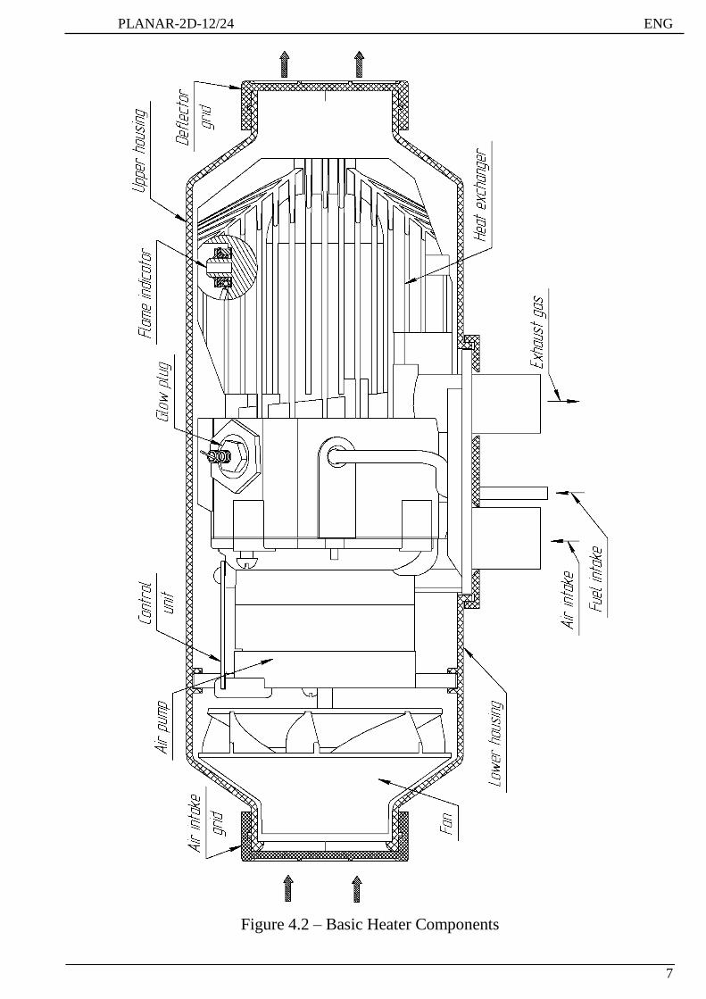
The heater is a self-contained heating device comprising the following:
- Heating device (See Figure 4.2 for basic components thereof);
- Fuel supply pump providing fuel for the combustion chamber;
- Ignition and indicator device (control panel);
- Wiring harness connecting heater fittings to the vehicle battery.
The heater’s operating principle is based on heating air driven through the heater’s
heat exchange system.
The heat sources are fuel combustion gases from the combustion chamber. The
resulting heat warms the walls of the heat exchanger, which is air-blown from the outside.
Air passes through the ribbing of the heat exchanger and enters the passenger
compartment or other compartments of the vehicle.
Upon ignition, control unit of heater checks the heater to ascertain whether fittings
such as the flame indicator (the indicator of a flame combines in itself functions of the
sensor of temperature of the heat exchanger and the overheat sensor), air pump motor,
plugs, fuel supply pump and the electric circuits thereof are working properly.
If no problem is detected, the ignition process starts.
In accordance with the preset sequence, the combustion chamber is fore-purged and
the heating plug warms up to the required temperature. Air and fuel starts to enter the
combustion chamber under the same procedure, whereupon the ignition process is
initiated. Once stable combustion is achieved, the heating plug switches off. Flame control
is provided by the flame indicator. All processes involved in heater operation are
monitored by the control unit.
The control unit controls heat exchanger temperature and halts the combustion process
as soon as the temperature exceeds the specified limit. The heater may be switched off at
any time.
Pressing the heater deactivation command stops the fuel entering and the combustion
chamber is purged with air.
During automated operation control of the heater in emergency situations, bear in mind
the following:
1) In the event of ignition failure, the process will be repeated. The heater will switch
off following two consecutive ignition failures;
2) If a combustion failure occurs while the heater is in operation, the heater will start
repeated ignition. The maximum number of starts for this reason – no more than 3 times;
3) If the heat exchanger is overheated (maybe as a result of closure of the heater
inlet/outlet vents), the heater will switch off automatically;
4) If voltage drops below 10V (20V) or exceeds 16V (30V) the heater will switch off.
5) In the event of emergency shutdown, the indicator will show the information
according to the code of malfunction see table 6.1;
Page 5
ENG PLANAR-2D-12/24
6
1. View of connector show from contact side;
2. * - Color of tags on wires;
3. ** - At the additional order.
4. *** - Example of connection of a heater to the car
Figure 4.1- Wiring Diagram
Page 6
PLANAR-2D-12/24 ENG
7
Figure 4.2 – Basic Heater Components
Page 7
ENG PLANAR-2D-12/24
8
5. Control Unit
The control unit and the control panel control the heater.
The control unit performs the following functions:
а) initial diagnostics (serviceability check) of heater fittings during ignition,
b) diagnostic of heater elements throughout operation,
c) heater activation/deactivation by command from control panel;
d) combustion process control;
e) automated switching of ventilation after the combustion process stopped;
f) automated deactivation of the heater occurs:
- in the event of failure of one of the controlled elements,
- when any parameter exceeds the specified limit (heat exchanger temperature,
supply voltage, combustion chamber flame failure)
- аt flame failure in the combustion chamber
6. Control Panel Functions
6.1 Control panel «ПУ-10М».
The ПУ-10М control panel is delivered under the
additional order, it is intended for management of
heater work.
The panel is intended for:
a) start and stop a heater in a manual mode;
b) changes in a manual operating mode of a
heating capacity (heating temperature);
c) indications of a condition of a heater on a
light-emitting diode.
On the front panel of the control panel are located
(see fig. 6.1):
1) keyboard switch (pos.1);
2) potentiometer (pos.2);
3) light-emitting diode (pos.3).
12
3
12
3
Fig. 6.1 - ПУ-10M Control panel
The keyboard switch is intended for switching on/off the heater.
The potentiometer at turn changes heating capacity from 0,8 to 1,8 kW, and at
established remote cabine temperature sensor changes temperature from 15ºC to 30ºC.
Light-emitting diode of pos. 3 shows a mode of a heater:
- shines red color – a mode of heating or a ventilation mode at the beginning and at the
end of heater work;
- blinks red color - at malfunction (faulty). The quantity of blinkings after a pause
corresponds to a type of malfunction (see table 6.1);
- doesn't shine - at an idle heater.
Page 8
PLANAR-2D-12/24 ENG
9
6.2 The control panel «ПУ-8М» is intended for:
- heater activation and deactivation in manual mode;
- choice of a way of management «on power» or «on temperature»;
- activation of "waiting" mode
- indication of the established temperature or power;
- indications of temperature of one of 3х sensors (built in the heater, built in the control
panel or remote – cabin temperature sensor, if it is connected);
-failure code indication in case of heater failure while operation.
6.2.1 The front board of the panel contains: four-digit light emitting diode (LED)
indicator, three LEDs and three knobs. Functionality of the knobs and LEDs. (fig.6.2)
Fig. 6.2- Control panel «ПУ-8М»
The way of management "on power" is intended for the fastest heating of the room. If
to establish "max" power, the heater will constantly work with the maximum heating
capacity. In operating time of a heater it is possible to set it's power (8 steps of power).
The way of management "on temperature" is intended for maintenance in necessary
temperature. If the measured temperature is less established, the heater will work at "max"
power. When indoors temperature will come nearer to the established value, heating
capacity of a heater will start decreasing. And, the less difference of temperatures, the is
less heater heating capacity.
Waiting mode is a mode on which process of burning stops and air ventilation
indoors begins. Ventilation is necessary for maintenance of identical temperature in all
room. During ventilation temperature in the room is constantly measured and if it
becomes lower than established, the heater will be started again.
Page 9
ENG PLANAR-2D-12/24
10
Features of work of a heater:
1) "Waiting" mode is compatible to way of management "on temperature" and isn't
compatible to way of management "on power". The heater won't stop burning during the
work "on power" irrespective of light-emitting diode No. 2 indication.
2) After each switching off of a heater there is a dumping of activation of "waiting"
mode.
3) At a choice of a way of management "on power" the heater constantly works at the
chosen thermal power. At achievement of comfortable temperature we recommend to
reduce power or to make air ventilation of the room.
4) On the mode "on temperature" the heater will work for maintenance of the
established temperature, thus its thermal power will change from max to min depending on
air temperature. The air temperature is higher, the less heat makes a heater.
At achievement of the established temperature:
- if the waiting mode isn't activated, the heater will pass a mode to "min". Further work
of a heater depends on temperature indoors:
1) if temperature continues to increase, the heater will continue to work at power
"min". It is possible to switch off a heater manually;
2) if temperature starts going down, the heater will smoothly increase the developed
thermal power, trying to maintain indoors established temperature. It is possible
to switch off a heater manually.
- if the waiting mode is activated, on reaching the set temperature the heater will pass
into waiting mode. On the waiting mode burning stops and air ventilation indoors begins.
When temperature indoors will fall on 5ºС below the established there will be the next
ignition of a heater. It is possible to switch off a heater manually.
6.2.2 Control Panel installation and connection
Control Panel is installed in cabin or passengers compartment on the dashboard or
any other comfortable for the driver place.
The control Panel is fixed with double-faced adhesive tape, which is stuck to the back
side of the Control Panel. You can take out wires of the unit from its back or side cover. It
is necessary to degrease the surface used for Control panel installation. Take off protective
film from the tape and install the Control Panel on the prepared surface.
If installation of the control panel is made by means of a holder, it is necessary to fix
two self-tapping screws a holder on the dashboard, and then to latch in it the control panel.
The connection of the Control panel to the heater is performed according wiring
diagram (fig. 4.1)
6.2.3 Complex checkup of the Control Panel after installation
After installation and connection of the Control panel to the heater the checkup is
performed in following way:
-set up the necessary operation mode on the Control panel;
-check activation and deactivation of the heater;
-check deactivation of the heater while artificial failure (take off the connector from
the fuel pump during operation mode of the heater), while this the malfunction code appears
on the indicator.
Page 10
PLANAR-2D-12/24 ENG
11
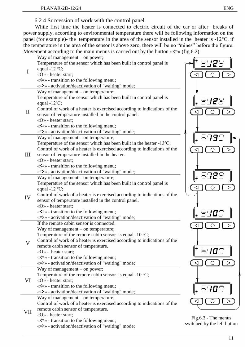
6.2.4 Succession of work with the control panel While first time the heater is connected to electric circuit of the car or after breaks of
power supply, according to environmental temperature there will be following information on the
panel (for example)- the temperature in the area of the sensor installed in the heater is -12°C, if
the temperature in the area of the sensor is above zero, there will be no “mines” before the figure.
Movement according to the main menus is carried out by the button «» (fig.6.2)
I
Way of management – on power;
Temperature of the sensor which has been built in control panel is
equal -12 ºС;
«О» - heater start;
«» - transition to the following menu;
«» - activation/deactivation of "waiting" mode;
Fig.6.3.- The menus
switched by the left button
II
Way of management – on temperature;
Temperature of the sensor which has been built in control panel is
equal -12ºС;
Control of work of a heater is exercised according to indications of the
sensor of temperature installed in the control panel.
«О» - heater start;
«» - transition to the following menu;
«» - activation/deactivation of "waiting" mode;
III
Way of management – on temperature;
Temperature of the sensor which has been built in the heater -13ºС;
Control of work of a heater is exercised according to indications of the
sensor of temperature installed in the heater.
«О» - heater start;
«» - transition to the following menu;
«» - activation/deactivation of "waiting" mode;
IV
Way of management – on temperature;
Temperature of the sensor which has been built in control panel is
equal -12 ºС;
Control of work of a heater is exercised according to indications of the
sensor of temperature installed in the control panel.
«О» - heater start;
«» - transition to the following menu;
«» - activation/deactivation of "waiting" mode;
V
If the remote cabin sensor is connected.
Way of management – on temperature;
Temperature of the remote cabin sensor is equal -10 ºС;
Control of work of a heater is exercised according to indications of the
remote cabin sensor of temperature.
«О» - heater start;
«» - transition to the following menu;
«» - activation/deactivation of "waiting" mode;
VI
Way of management – on power;
Temperature of the remote cabin sensor is equal -10 ºС;
«О» - heater start;
«» - transition to the following menu;
«» - activation/deactivation of "waiting" mode;
VII
Way of management – on temperature;
Control of work of a heater is exercised according to indications of the
remote cabin sensor of temperature.
«О» - heater start;
«» - transition to the following menu;
«» - activation/deactivation of "waiting" mode;
Page 11
ENG PLANAR-2D-12/24
12
Activation - deactivation of "waiting" mode is carried out by the button «» (fig.6.4).
Fig.6.4 - The menus switched by the right button
После запуска отопителя, в зависимости от выбранного способа управления
необходимо установить величину мощности или температуры.
If power control is selected, pressing knobs with arrows
«» (decreasing), « » (increasing) – you can set up the
necessary power. The indicator shows the scale according
which the power is set up (fig. 6.5).
Fig.6.5 – Management on
power
Fig.6.5.а – Management on
temperature
If temperature control is selected , pressing knobs with
arrows «» (decreasing), « » (increasing) – you can
set up the necessary temperature ( fig. 6.5a). The
temperature is set within 1°C (33.8°F) to 30°C (86°F) in a
zone of the installed sensor.
With the view to energy saving , the indicator stops glowing 20 seconds after last
pressing of any knob, while this LED№1 or LED№3 is :
- lightning constantly if the heater is activated;
- blinking rarely (1 time per 1,5 second) if the heater is not activated; ( ).
- blinking while fault (1 time per second);
- blinking frequently (5 times per second) while deactivation of the heater (while
purging) ( ).
To restart the indication there’s need to press any knob.
Attention!
1. If cabin temperature sensor circuits are disconnected heater will go working
on middle power Operation mode.
2.While heater activation without setting operation modes it is necessary to
press the knob «O» one time if the indicator is lightning, and 2 times if the indicator
is not lightning.
Page 12
PLANAR-2D-12/24 ENG
13
6.2.5 Heater deactivation.
For switching off of a heater it is necessary to press the O button. Thus supply of fuel
stops, the combustion chamber purge within 3-5 minutes is made, the light-emitting diode
No. 1 or No. 3 will often blink until the termination of a purge (fig 6.6)
Fig 6.6-Purge
Attention!
It is forbidden to switch off electric power supply before purge cycle is finished.
6.2.6 Indication of malfunction code while failures in heater operation
While heater activation and operation there can be malfunctions. In case of
malfunction the control unit deactivates the heater automatically. Every malfunction is
coded and automatically appears on the indicator (Fig 6.7). While this, malfunction‘s code
and the LED showing the operation mode of the heater will blink rarely. The heater’s
malfunction codes are described in table 6.1. Pressing of any knob of the control panel will
switch off indication of the malfunction code and bring the control panel in initial state.
Fig 6.7 The panel the indicator at heater malfunction
6.2.7 Possible malfunctions
If after pressing any knob of the Control Panel the indicator is not lightning, there
should be checked:
- fuses-25A;
- connectors and wires.
The Control Panel is not subjected to repair, it should be replaced for a new one.
Page 13
ENG PLANAR-2D-12/24
14
Table 6.1- Malfunction codes Quantity of
blinkings
Malfunction
code Problem description
Commentary
Problem solution
1 1
Overheat on the upper bound
of temperature.
Overheat on the growth rate of
temperature of the case.
Check the inlet/outlet pipe of
the heater for unpumped heated
air flow. Check the flame
indicator (overheating sensor)
on the heat exchanger, replace if
necessary.
12 2 Overheat in a control unit
zone.
Check the inlet/outlet pipe of
the heater for unpumped heated
air flow.
5 5
Break of the flame indicator
(overheating sensor of the
housing)
Check the flame indicator
(overheating sensor) on the heat
exchanger, replace if necessary.
6 6 Built-in temperature sensor on
control unit failure. Replace the control unit
4 9 Heating plug failure Check the plug and replace if
necessary
11 10 Air pump motor malfunction
Check the electric wiring of the
air pump motor, replace the air
pump, if necessary.
9 12 Shutdown, voltage boost
Check the battery, regulator and
power supply wiring. The
voltage between 1 contact and 2
contact of connector XS2 (see
connection layout fig. 4.1)
should not exceed 16V (30V)
2 13 No further activation attempt
is possible
If possible quantity of
activation attempts is used,
check the heating plug, fuel
level and fuel supply system.
Check combustion air system
and exhaust pipe line
9 15 Shutdown, low voltage
Check the battery, regulator and
power supply wiring. The
voltage between 1 contact and 2
contact of connector XS2 (see
fig. 4.1) should be not less 10V
(20V)
10 16
During a purge, the flame
indicator (overheating sensor
of the housing) didn't cool
down
Check the inlet/outlet pipe of
the heater for unpumped heated
air flow. Check the flame
indicator (overheating sensor)
on the heat exchanger, replace if
necessary.
Page 14
PLANAR-2D-12/24 ENG
15
7 17 Fuel pump failure
Check fuel pump wiring for
short-circuit fault or
disconnection fault. Replace the
pump if necessary.
8 20 No connection between
Control panel and the heater Check wiring, connectors.
11 27 Air pump failure. Motor
won’t rotate Check the wiring of the air
pump, control unit, replace if
necessary. 11 28 Air pump failure. The motor
rotates without control
3 29
The admissible number of
breakdowns of a flame in
operating time is exceeded
Check the fuel level and fuel
supply system. Check
combustion air system and the
exhaust pipe line. If the heater
can be started, check fuel pump
and replace if necessary.
--- 78 Fixed the flame failure when
the time of pre-haeter work.
It is shown for your
information. Check Check
tightness of clamp on the fuel
line,fuel line leaks, tightness of
the fitting on the fuel pump.
6.3 Use and connection to the vehicle remote alarm system for activation and
switching off the heater with the help of transmitter.
You can use vehicle remote alarm system to control the heater operation if there is an
additional channel.
The relay having normally opened contacts is connected to an exit of this channel (the relay
isn't included in the delivery package). Contacts of the relay should be connected to wires of the
modem harness before XP8 connector (see fig. 4.1).
The ends of wires are closed by a thermoshrinkable tube. For connection of a heater it is
necessary to strip out the ends of wires and to connect them (to solder) to the car relay (if
necessary to extend wires).
Control of the heater can be done in two ways: short-circuit contacts of relay (time of the
closed state 0.5 to 3 seconds), and long-circuit closure (more than 3 seconds). Short first impulse
will starts the heater, next short impulse stops the heater.
With long impulse of the contacts of relay a command “Start” will be formed. When contacts
will be open - the command "Stop" will be formed.
After start the heater will start working at "max" mode on power.
It is possible to stop the operation of the pre-heater with the help of the transmitter of vehicle
remote alarm system and from the control panel.
Type of the transmitter has no significant meaning, the only requirement is that the relay
current consumption must not exceed current capacity of the remote alarm system channel.
The harness of XP8 connector to which vehicle remote alarm system is connected, is used
also for connection of the modem. Thus work of a heater can be operated from all connected
devices (the control panel, the modem, an vehicle remote alarm system).
Page 15
ENG PLANAR-2D-12/24
16
6.4 The use and installation of the modem to run the heater.
Operation of the heater can be controlled over the phone using a modem and a special
application. For remote control operation of the heater is possible to connect the control
unit to the GSM modem, which is designed for use in harsh conditions (cold, vibration,
etc.). In modem as in your phone, the SIM card can be installed. On account of this SIM
card should be a small amount to make the modem work correctly.
Just do not forget to replenish the account. For simplicity of control of balance and
payment (provided that the SIM card of the modem and your cell phone are served at one
mobile operator) the SIM card of the modem can be transferred to personal account of
your cell phone, having written the corresponding application in salon of mobile operator.
Set the modem at any convenient, clean place. Connect the antenna to the modem and
bring antenna to the open space (for example, on the windshield ) . Connect the modem to
the heater (according to fig. 4.1 and fig. 7.1 ) and test it .
Heater control is carried out using an application installed on the mobile phone (refer
to the modem).
From the main desktop, or from the application menu, run the application
«TeplostarSMS" logo .
If it is the first application launch on this device, it is necessary to enter phone number of
the SIM card inserted into the modem (further this input isn't required).
If it is the first application launch on this device, it is necessary to
enter phone number of the SIM card inserted into the modem
(further this input isn't required).
For start of a heater it is necessary to press "START", for a stop -
"STOP".
For change of application controls it is necessary to use the side
menu: to press the button in the right top corner or make "slide to
the left".
The following settings are available:
SMS delivery notification – the notice of receiving the SMS by the
modem.
Faults notification – the notice of malfunctions in product work.
For obtaining information on a status of a heater it is necessary to
press "CHECK STATUS", in reply information on product
Fig.6.8 – appendix
screen*
operating time will come (if it works), a malfunction code (if it is), the air temperature
and value of supply voltage.
For obtaining information on the product it is necessary to press "About device", the
SMS with a serial number of a heater and the version of the software established on a
heater in reply will come..
You can see the detailed instruction on work in «The instruction of the user for the
TeplostarSMS appendix» (in a modem set).
* Appearance of the appendix can differ from presented in fig. 6.8.
Page 16
PLANAR-2D-12/24 ENG
17
7. Scope of Supply
See Figure 7.1 for scope of supply and connection diagram of basic heater components.
For list of basic heater components, see Table 7.1.
Figure 7.1 – Connection Diagram of Basic Heater Components
Page 17
ENG PLANAR-2D-12/24
18
Table 7.1
* It is delivered under the additional order.
**Delivery of an exhaust pipe 31 with not established screen 6 is possible.
Screen installation to make according to fig. 7.1.
No. Designation Pieces Per
Set
1 Heater (12V or 24V) 1
2 Fuel Supply Pump Harness 1
3 Power Supply Harness 1
4 Air Intake 1
5 Heat insulation 1
6 Screen 1
7* Fuel tank 1
8* Holder with gasket 3
9 Clamp 1
10 Control panel «ПУ-8М» with harness or «ПУ-10М» 1
11 Fuel pump 24V or 12V 1
12* The sensor in a cabin 1
13* Modem 1
14 Fuel supple intake 1
15* Electromagnetic locking valve 1
17 Holder 2
21 Air Inlet Clamp 1
25 Connecting Tube (polyamide) L = 5500 mm 1
27 Sleeve L= at least 70 mm (or one hose L= 4 x 70 = 280 mm) 4
30 Clamp 2
31** Exhaust Pipe L=1000mm 1
32 Bolt М6х16 5
33* Bolt M6x20 6
34 Bolt M6x25 1
36* Screw 6.4х14 6
38 Nut М6 16*
41 Enlarged Flat Washer 6 11*
43 Split Washer 6 14*
45 Cap connector AMP 282762-1 1
49 Clamp Mikalor 20х32/9 W1 1
50 Clamp АВА min 10/9 8
52 Clamp Mikalor 25х40/9 W1 1
53 Plastic Clamp 200x3.6 15
54 Exhaust Pipe Clamp 26-28 Vaper 1
Page 18
PLANAR-2D-12/24 ENG
19
8. Installation Requirements
8.1 Heater Installation
Installed the heater indoors while bearing in mind the permissible operating
positions shown in Figure 8.1. The figure 8.1 shows the two maximum assembly positions
of the heater. Positioned the heater’s inlet vent in such a way to prevent absorption of
vehicle/heater exhaust gas in normal operating conditions. The gap between the
walls/partitions and the edge of the inlet vent shall be at least 50 mm (see Figure 8.1). The
distance between the walls/partitions and the edge of the outlet vent shall be at least
150mm. When assembling or operating the heater, ensure that no foreign objects enter the
inlet/outlet vents. Prior to assembly, ensure availability of spare heating plug and bear in
mind dismantlement requirements, as this will permit easier maintenance in future. At
installation of the heater check that its case had no contact both with a floor and with other
parts of a cabin or a manned compartment. See Figure 8.2 for how to position mounting
holes to install the heater into the motor vehicle casing.
At installation to the heater of air ducts, they shouldn't have the deformations
reducing the section through passage of an air duct. The maximum length of an output air
duct shouldn't exceed 5 meters of total length.
ATTENTION ! To ensure reliable performance, follow the above
recommendations carefully. Install the heater horizontally as shown in Figure 8.1.
Figure 8.1 – Variants of installation of a heater.
Page 19
ENG PLANAR-2D-12/24
20
Figure 8.2– Mounting Holes Used for Heater Installation
8.2 Air Inlet Installation
Air necessary for burning, should not be soaked up from salon or a cabin and a car luggage
space. Position the pipe’s air inlet vent to prevent snow entering or choking the pipe and to
allow incoming water to run off. The entrance aperture of an air inlet is forbidden to
have against a running air stream at car movement.
8.3 Exhaust Pipe Installation
When installing the exhaust pipe, be mindful of its high operating temperature. Cut the
exhaust pipe (a flexible corrugated metal hose) to size. Fix the exhaust pipe in place using
clamps and position it at a slight angle following the trajectory of gas flow. To protect
some parts of the vehicle (electric wiring and other harness) from high temperatures, there
must be heat insulation installed.( pos.3, fig.7.1)
To achieve a tight fit, prior to connecting the exhaust pipe to the heater pipe, make a
saw-cut of about 15mm along the length of the exhaust pipe without going beyond the
gripped part of the pipe. Ensure that the end of the exhaust pipe does not come into contact
with the rubber seal of the heater. Direct exhaust gas outside. Position the gas outlet vent
and the air inlet vent in such a way as to prevent exhaust gas from entering the combustion
chamber. Ensure that exhaust gas does not enter the passenger compartment of the vehicle
and that it does not get sucked in through the vehicle fan.
Do not allow exhaust gas to affect the performance of vehicle components. Position
the exhaust pipe outlet vent so as to prevent snow entering or choking the pipe and to
allow incoming water to run off. At the vent of the exhaust pipe the screen is installed, this
necessary for stable operation of the heater while working low idle. If this screen is not
installed, install it according fig.7.1
The exhaust outlet of an exhaust pipe is forbidden to have against a running air
stream at car movement.
Page 20
PLANAR-2D-12/24 ENG
21
8.4 Installation of a fuel tank on the car
The fuel tank is established according to figure
8.3. A fuel tank it is necessary to have so that the
exit of fuel which can flow out from its bulk mouth,
on the earth was provided.
The bulk mouth of a fuel tank should not be in
salon, a luggage carrier, in a motor compartment. If
the bulk mouth is located on a vehicle lateral face
the filler cap in the closed position should not
support car’s body dimensions. Fuel which can spill
at filling of a fuel tank, should not get on exhaust
systems and electro wires. It should be taken away
on a ground.
For the purpose of an exception of leak of fuel
from a fuel tank by gravity at infringement of
tightness of the fuel pump, a fuel tank it is
preferable to have so that the fuel maximum level
was below a cut of a fuel tube of a heater.
Figure 8.3 - Installation of a fuel
tank on the car
ATTENTION! Before a heating season it is necessary to check a fuel tank. If the fuel was stored
long time in a tank (for example from last heating season), it needs to be removed! To
wash out a tank with gasoline or kerosene and to fill in new diesel fuel. This procedure is
intended for removal of a deposit in fuel at long storage. Not performance of this
procedure can lead to a contamination or failure of the fuel pump and the raised sooting in
the combustion chamber.
Page 21
ENG PLANAR-2D-12/24
22
8.5 Installation a fuel supply intake in a regular tank of the car
Fuel can enter the heater through a fuel supply intake from the regular fuel tank of the car.
Fuel supply intake must be installed into regular fuel tank of the car according to
fig. 8.4,a). Perform installation of special washer with fuel supply intake to the tank inlet
according to fig.8.4,b) Perform installation of the fuel supply line from fuel supply intake
to the heater according to fig.8.5.
1 - fuel supply intake 4 - washer 8
2 - nut M8 5 - special washer
3 - washer 8 6 - gasket
Fig 8.4 – Fuel supply intake installation in a regular tank of the car
1 – regular fuel tank of car 4 – fuel pump
2 – fuel supply intake 5 – sleeve
3 – fuel supply line d=2 mm
Figure 8.5 – Installation Diagram for Heater Fuel Supply System Using a fuel supply
intake
Page 22
PLANAR-2D-12/24 ENG
23
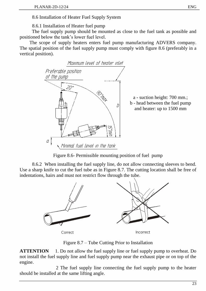
8.6 Installation of Heater Fuel Supply System
8.6.1 Installation of Heater fuel pump
The fuel supply pump should be mounted as close to the fuel tank as possible and
positioned below the tank’s lower fuel level.
The scope of supply heaters enters fuel pump manufacturing ADVERS company.
The spatial position of the fuel supply pump must comply with figure 8.6 (preferably in a
vertical position).
a - suction height: 700 mm.;
b - head between the fuel pump
and heater: up to 1500 mm
Figure 8.6- Permissible mounting position of fuel pump
8.6.2 When installing the fuel supply line, do not allow connecting sleeves to bend.
Use a sharp knife to cut the fuel tube as in Figure 8.7. The cutting location shall be free of
indentations, hairs and must not restrict flow through the tube.
Figure 8.7 – Tube Cutting Prior to Installation
ATTENTION 1. Do not allow the fuel supply line or fuel supply pump to overheat. Do
not install the fuel supply line and fuel supply pump near the exhaust pipe or on top of the
engine.
2 The fuel supply line connecting the fuel supply pump to the heater
should be installed at the same lifting angle.
Page 23
ENG PLANAR-2D-12/24
24
8.7 Installation of Heater Electric Circuit
Heater wire harnesses shall be installed in compliance with the heater wiring system
as shown in Figure 4.1. When installing, do not allow the wire harnesses to become
overheated, deformed or dislodged during vehicle use. Attach the harnesses to the vehicle
fittings using plastic clamps.
Attention! Remove the fuse prior to installation.
8.8 Installation the sensor in a cabin.
The sensor in a cabin (fig. 8.8) is intended for air temperature measurement in a zone
of its installation and allows to work in a mode of maintenance of the set temperature
within 15 30C.
The sensor is installed in a cabin (or the manned volume of vehicle) in a place
convenient for the driver (personnel). The maximum length of a cable of the sensor is
5000mm. After installation the of the sensor it must be connected to the XS4 socket of the
heater.
(1 – microcircuit;. 2 - Connector)
Figure 8.8 – The sensor in a cabin.
8.9 Installation the electromagnetic locking valve.
The electromagnetic locking valve serves for giving or overlapping of supply of fuel
in a heater. The valve is installed in front of the fuel pump and prevents supply of fuel in
idle at present a heater. Normally the valve — is closed. When giving on valve the supply
voltage the coil of an electromagnet takes away a rod with a locking element from a
saddle of the valve and opens the pass for a fuel. At removal of supply voltage from the
valve the returnable spring presses a rod with a locking element to a saddle of the valve
blocks the pass for a fuel.
Page 24
PLANAR-2D-12/24 ENG
25
9. Post-installation Testing
9.1 When installing, ensure that:
- the fuel supply lines of the fuel supply system are leak-proof and all clamps are
securely tightened,
- the electric contacts of the harnesses and heater elements are securely installed,
9.2 Install fuse 25А .
9.3 Fill the fuel pipe system with fuel with the help of fuel pumping device (fuel
pumping device УПТ-1 can be ordered at manufacturer) or repeated inclusion of a heater.
After filling the system check that the fuel pump system is not leaking.
9.4 Check that the heater is working on min and max modes:
The process of activation begins with purging of the combustion chamber. After purging
the process of combustion begins and the heater goes on working in operation mode.
9.5 Deactivate the heater. While switching off the heater the fuel stops entering and
the process of ventilation of the combustion chamber and heat exchanger starts.
9.6 Activate the heater while the vehicle engine is running and ensure that the heater
is operational.
ATTENTION! 1 When performing initial ignition following installation, the fuel
supply line should be filled with fuel using a fuel pumping device until the fuel level
reaches the inlet plug of the heater. If there is no pumping device, restart the heater
as many times as necessary to fill the fuel supply line.
2 Remember that each time the heater fails to start at the first
attempt, the heater will be restarted automatically by the control unit. If the heater
is not activated after 2 attempts, there will be malfunction code on the Control panel.
10. Recommendations
10.1 To ensure consistent performance, the heater should be switched on for up to 5
minutes each month throughout the year (warm seasons included). This will prevent the
moving parts of the fuel supply pump from sticking, (which may be caused by leaving the
heater movable fittings in low-quality fuel for a long period of time).
10.2 Reliable performance depends on the type of fuel used depending on the
atmospheric temperature.
10.3 Check the battery charge level on a regular basis.
10.4 Reliable operation of heater depends on the type of fuel used. Type of fuel
should be in accordance with GOST 305-82, depending on the ambient temperature (see
Table 10.1). May be used and the mixture of fuel according to Figure 10.
10.5 While long storage of the vehicle it is recommended to switch off the heater
from the vehicle battery to avoid its discharging (current consumption in non operation
mode 30-40 mA).
Page 25
ENG PLANAR-2D-12/24
26
Table 10.1
Ambient temperature, °C Fuel type or blend
0°С and above 0°С Diesel Л-0, 2-40 Or Л-02-62 ГОСТ 305-82
0°С – -5ºС (32°F – 23°F) Diesel З-0,2 mines 35 ГОСТ 305-82
-5ºС - - 20ºС (23°F - -4°F) Diesel З-0,2 mines 35 ГОСТ305-82 or
Diesel З-0,2 mines 45 ГОСТ305-82
Lower then -20ºC (-4°F) Diesel A-0.4 ГОСТ 305-82
Figure 10 - Amount of kerosene mixed with diesel fuel, depending on the ambient
temperature.
11. Remedial Procedure for Heater Ignition Problems
11.1 Certain problems may be solved without contacting a maintenance station.
If the heater does not operate when switched on, proceed to the following steps:
1) Check the fuel level in the tank and in the fuel supply line beyond the fuel supply pump;
2) Check fuse 25А;
3) Check to see that all the contacts of the connectors and the fuse block are securely
joined (contact corrosion is possible);
4) disconnect blocks XP2 and XS2 of the power supply harness connector (fig 4.1) for 1-2
min and then connect them.
11.2 All other types of heater malfunction will be indicated automatically on the
control panel according to the malfunction code.
11.3 If there are malfunctions except those specified in 11.1 does not remedy any
of the problems that you may be having, please contact an authorized maintenance station.
ATTENTION! The heaters completed with glow plug with a glow pin of production
of Japan. This glow plug need to be checked for working capacity giving on it voltage 9V
(for heaters with voltage 12V) or 18V (for heaters with voltage 24V).
Page 26
PLANAR-2D-12/24 ENG
27
12. Transportation & Storage
12.1 The heaters are safe to transport and may be transported by any means of
transport, including air and rail transport providing the packed products are protected from
atmospheric precipitations and climatic factors as per requirements specified in Section 5
of GOST 15150-69 and mechanical effects as per requirements specified in Category C of
GOST 23216-78.
12.2 As far as climatic factors are concerned, transportation and storage conditions
shall comply with storage requirements set out in Section 2 of GOST 15150-69.
12.3 Heater period of storage in packing of the enterprise of the manufacturer - 24
months
13. Warranty
13.1The warranty term of exploitation of heater outflows under reaching one of next
terms:
- the term of exploitation attained 18 months after the sale of good;
- good worked a warranty resource - 1000 hours;
- mileage with established heater exceeds 50,000 km.
13.2 Appointed tenure of employment of heater - 3000 hours.
13.3 In default of stamp of organization with naming the date of sale a warranty
term is calculated from the date of making of heater.
13.4 A manufacturer does not accept claim on incompleteness and mechanical
damages after sale of heater.
13.5 A producer guarantees normal work of the heater on condition of observance
by the consumer of all rules of exploitation, transportage and storage, indicated in this
guidance. If a malfunction was found out during a warranty term, then she will be set free
of charge. Installation of heater the organizations authorized by a producer must conduct.
In this case, the warranty card is filled column «Information on installation.»
Warranty obligations do not spread to the defects arising up as a result :
- force-majeure circumstances: shots of lightning, fire, flood, impermissible violations
of supply voltage,
- road a transport incident;
- failures to observe of rules of exploitation, storage and transporting;
- repair or adjusting, if they are conducted by the organizations, not authorized by a
producer on installation of the heater and warranty repairing;
- refuse of work of heater by reason of contamination of combustion chamber;
- violations of work of electrical equipment of car;
- independent repair of heater or the use of unoriginal spare parts.
Page 27
ENG PLANAR-2D-12/24
28
Заметки / Notes